JP7350737B2 - Control of electric vehicle charging current - Google Patents
Control of electric vehicle charging currentDownload PDFInfo
- Publication number
- JP7350737B2 JP7350737B2JP2020526551AJP2020526551AJP7350737B2JP 7350737 B2JP7350737 B2JP 7350737B2JP 2020526551 AJP2020526551 AJP 2020526551AJP 2020526551 AJP2020526551 AJP 2020526551AJP 7350737 B2JP7350737 B2JP 7350737B2
- Authority
- JP
- Japan
- Prior art keywords
- charging
- maximum current
- charging station
- subgroup
- active
- Prior art date
- Legal status (The legal status is an assumption and is not a legal conclusion. Google has not performed a legal analysis and makes no representation as to the accuracy of the status listed.)
- Active
Links
Images


Classifications
- B—PERFORMING OPERATIONS; TRANSPORTING
- B60—VEHICLES IN GENERAL
- B60L—PROPULSION OF ELECTRICALLY-PROPELLED VEHICLES; SUPPLYING ELECTRIC POWER FOR AUXILIARY EQUIPMENT OF ELECTRICALLY-PROPELLED VEHICLES; ELECTRODYNAMIC BRAKE SYSTEMS FOR VEHICLES IN GENERAL; MAGNETIC SUSPENSION OR LEVITATION FOR VEHICLES; MONITORING OPERATING VARIABLES OF ELECTRICALLY-PROPELLED VEHICLES; ELECTRIC SAFETY DEVICES FOR ELECTRICALLY-PROPELLED VEHICLES
- B60L53/00—Methods of charging batteries, specially adapted for electric vehicles; Charging stations or on-board charging equipment therefor; Exchange of energy storage elements in electric vehicles
- B60L53/60—Monitoring or controlling charging stations
- B60L53/62—Monitoring or controlling charging stations in response to charging parameters, e.g. current, voltage or electrical charge
- B—PERFORMING OPERATIONS; TRANSPORTING
- B60—VEHICLES IN GENERAL
- B60L—PROPULSION OF ELECTRICALLY-PROPELLED VEHICLES; SUPPLYING ELECTRIC POWER FOR AUXILIARY EQUIPMENT OF ELECTRICALLY-PROPELLED VEHICLES; ELECTRODYNAMIC BRAKE SYSTEMS FOR VEHICLES IN GENERAL; MAGNETIC SUSPENSION OR LEVITATION FOR VEHICLES; MONITORING OPERATING VARIABLES OF ELECTRICALLY-PROPELLED VEHICLES; ELECTRIC SAFETY DEVICES FOR ELECTRICALLY-PROPELLED VEHICLES
- B60L53/00—Methods of charging batteries, specially adapted for electric vehicles; Charging stations or on-board charging equipment therefor; Exchange of energy storage elements in electric vehicles
- B60L53/30—Constructional details of charging stations
- B60L53/305—Communication interfaces
- B—PERFORMING OPERATIONS; TRANSPORTING
- B60—VEHICLES IN GENERAL
- B60L—PROPULSION OF ELECTRICALLY-PROPELLED VEHICLES; SUPPLYING ELECTRIC POWER FOR AUXILIARY EQUIPMENT OF ELECTRICALLY-PROPELLED VEHICLES; ELECTRODYNAMIC BRAKE SYSTEMS FOR VEHICLES IN GENERAL; MAGNETIC SUSPENSION OR LEVITATION FOR VEHICLES; MONITORING OPERATING VARIABLES OF ELECTRICALLY-PROPELLED VEHICLES; ELECTRIC SAFETY DEVICES FOR ELECTRICALLY-PROPELLED VEHICLES
- B60L3/00—Electric devices on electrically-propelled vehicles for safety purposes; Monitoring operating variables, e.g. speed, deceleration or energy consumption
- B60L3/12—Recording operating variables ; Monitoring of operating variables
- B—PERFORMING OPERATIONS; TRANSPORTING
- B60—VEHICLES IN GENERAL
- B60L—PROPULSION OF ELECTRICALLY-PROPELLED VEHICLES; SUPPLYING ELECTRIC POWER FOR AUXILIARY EQUIPMENT OF ELECTRICALLY-PROPELLED VEHICLES; ELECTRODYNAMIC BRAKE SYSTEMS FOR VEHICLES IN GENERAL; MAGNETIC SUSPENSION OR LEVITATION FOR VEHICLES; MONITORING OPERATING VARIABLES OF ELECTRICALLY-PROPELLED VEHICLES; ELECTRIC SAFETY DEVICES FOR ELECTRICALLY-PROPELLED VEHICLES
- B60L53/00—Methods of charging batteries, specially adapted for electric vehicles; Charging stations or on-board charging equipment therefor; Exchange of energy storage elements in electric vehicles
- B60L53/60—Monitoring or controlling charging stations
- B60L53/67—Controlling two or more charging stations
- B—PERFORMING OPERATIONS; TRANSPORTING
- B60—VEHICLES IN GENERAL
- B60L—PROPULSION OF ELECTRICALLY-PROPELLED VEHICLES; SUPPLYING ELECTRIC POWER FOR AUXILIARY EQUIPMENT OF ELECTRICALLY-PROPELLED VEHICLES; ELECTRODYNAMIC BRAKE SYSTEMS FOR VEHICLES IN GENERAL; MAGNETIC SUSPENSION OR LEVITATION FOR VEHICLES; MONITORING OPERATING VARIABLES OF ELECTRICALLY-PROPELLED VEHICLES; ELECTRIC SAFETY DEVICES FOR ELECTRICALLY-PROPELLED VEHICLES
- B60L53/00—Methods of charging batteries, specially adapted for electric vehicles; Charging stations or on-board charging equipment therefor; Exchange of energy storage elements in electric vehicles
- B60L53/60—Monitoring or controlling charging stations
- B60L53/68—Off-site monitoring or control, e.g. remote control
- G—PHYSICS
- G05—CONTROLLING; REGULATING
- G05B—CONTROL OR REGULATING SYSTEMS IN GENERAL; FUNCTIONAL ELEMENTS OF SUCH SYSTEMS; MONITORING OR TESTING ARRANGEMENTS FOR SUCH SYSTEMS OR ELEMENTS
- G05B13/00—Adaptive control systems, i.e. systems automatically adjusting themselves to have a performance which is optimum according to some preassigned criterion
- G05B13/02—Adaptive control systems, i.e. systems automatically adjusting themselves to have a performance which is optimum according to some preassigned criterion electric
- G—PHYSICS
- G05—CONTROLLING; REGULATING
- G05B—CONTROL OR REGULATING SYSTEMS IN GENERAL; FUNCTIONAL ELEMENTS OF SUCH SYSTEMS; MONITORING OR TESTING ARRANGEMENTS FOR SUCH SYSTEMS OR ELEMENTS
- G05B19/00—Programme-control systems
- G05B19/02—Programme-control systems electric
- G05B19/04—Programme control other than numerical control, i.e. in sequence controllers or logic controllers
- G05B19/042—Programme control other than numerical control, i.e. in sequence controllers or logic controllers using digital processors
- H—ELECTRICITY
- H02—GENERATION; CONVERSION OR DISTRIBUTION OF ELECTRIC POWER
- H02J—CIRCUIT ARRANGEMENTS OR SYSTEMS FOR SUPPLYING OR DISTRIBUTING ELECTRIC POWER; SYSTEMS FOR STORING ELECTRIC ENERGY
- H02J13/00—Circuit arrangements for providing remote indication of network conditions, e.g. an instantaneous record of the open or closed condition of each circuitbreaker in the network; Circuit arrangements for providing remote control of switching means in a power distribution network, e.g. switching in and out of current consumers by using a pulse code signal carried by the network
- H02J13/00002—Circuit arrangements for providing remote indication of network conditions, e.g. an instantaneous record of the open or closed condition of each circuitbreaker in the network; Circuit arrangements for providing remote control of switching means in a power distribution network, e.g. switching in and out of current consumers by using a pulse code signal carried by the network characterised by monitoring
- H—ELECTRICITY
- H02—GENERATION; CONVERSION OR DISTRIBUTION OF ELECTRIC POWER
- H02J—CIRCUIT ARRANGEMENTS OR SYSTEMS FOR SUPPLYING OR DISTRIBUTING ELECTRIC POWER; SYSTEMS FOR STORING ELECTRIC ENERGY
- H02J13/00—Circuit arrangements for providing remote indication of network conditions, e.g. an instantaneous record of the open or closed condition of each circuitbreaker in the network; Circuit arrangements for providing remote control of switching means in a power distribution network, e.g. switching in and out of current consumers by using a pulse code signal carried by the network
- H02J13/00006—Circuit arrangements for providing remote indication of network conditions, e.g. an instantaneous record of the open or closed condition of each circuitbreaker in the network; Circuit arrangements for providing remote control of switching means in a power distribution network, e.g. switching in and out of current consumers by using a pulse code signal carried by the network characterised by information or instructions transport means between the monitoring, controlling or managing units and monitored, controlled or operated power network element or electrical equipment
- H02J13/00022—Circuit arrangements for providing remote indication of network conditions, e.g. an instantaneous record of the open or closed condition of each circuitbreaker in the network; Circuit arrangements for providing remote control of switching means in a power distribution network, e.g. switching in and out of current consumers by using a pulse code signal carried by the network characterised by information or instructions transport means between the monitoring, controlling or managing units and monitored, controlled or operated power network element or electrical equipment using wireless data transmission
- H—ELECTRICITY
- H02—GENERATION; CONVERSION OR DISTRIBUTION OF ELECTRIC POWER
- H02J—CIRCUIT ARRANGEMENTS OR SYSTEMS FOR SUPPLYING OR DISTRIBUTING ELECTRIC POWER; SYSTEMS FOR STORING ELECTRIC ENERGY
- H02J13/00—Circuit arrangements for providing remote indication of network conditions, e.g. an instantaneous record of the open or closed condition of each circuitbreaker in the network; Circuit arrangements for providing remote control of switching means in a power distribution network, e.g. switching in and out of current consumers by using a pulse code signal carried by the network
- H02J13/00006—Circuit arrangements for providing remote indication of network conditions, e.g. an instantaneous record of the open or closed condition of each circuitbreaker in the network; Circuit arrangements for providing remote control of switching means in a power distribution network, e.g. switching in and out of current consumers by using a pulse code signal carried by the network characterised by information or instructions transport means between the monitoring, controlling or managing units and monitored, controlled or operated power network element or electrical equipment
- H02J13/00028—Circuit arrangements for providing remote indication of network conditions, e.g. an instantaneous record of the open or closed condition of each circuitbreaker in the network; Circuit arrangements for providing remote control of switching means in a power distribution network, e.g. switching in and out of current consumers by using a pulse code signal carried by the network characterised by information or instructions transport means between the monitoring, controlling or managing units and monitored, controlled or operated power network element or electrical equipment involving the use of Internet protocols
- H—ELECTRICITY
- H02—GENERATION; CONVERSION OR DISTRIBUTION OF ELECTRIC POWER
- H02J—CIRCUIT ARRANGEMENTS OR SYSTEMS FOR SUPPLYING OR DISTRIBUTING ELECTRIC POWER; SYSTEMS FOR STORING ELECTRIC ENERGY
- H02J3/00—Circuit arrangements for AC mains or AC distribution networks
- H02J3/12—Circuit arrangements for AC mains or AC distribution networks for adjusting voltage in AC networks by changing a characteristic of the network load
- H—ELECTRICITY
- H02—GENERATION; CONVERSION OR DISTRIBUTION OF ELECTRIC POWER
- H02J—CIRCUIT ARRANGEMENTS OR SYSTEMS FOR SUPPLYING OR DISTRIBUTING ELECTRIC POWER; SYSTEMS FOR STORING ELECTRIC ENERGY
- H02J7/00—Circuit arrangements for charging or depolarising batteries or for supplying loads from batteries
- G—PHYSICS
- G05—CONTROLLING; REGULATING
- G05B—CONTROL OR REGULATING SYSTEMS IN GENERAL; FUNCTIONAL ELEMENTS OF SUCH SYSTEMS; MONITORING OR TESTING ARRANGEMENTS FOR SUCH SYSTEMS OR ELEMENTS
- G05B2219/00—Program-control systems
- G05B2219/20—Pc systems
- G05B2219/26—Pc applications
- G05B2219/2639—Energy management, use maximum of cheap power, keep peak load low
- H—ELECTRICITY
- H02—GENERATION; CONVERSION OR DISTRIBUTION OF ELECTRIC POWER
- H02J—CIRCUIT ARRANGEMENTS OR SYSTEMS FOR SUPPLYING OR DISTRIBUTING ELECTRIC POWER; SYSTEMS FOR STORING ELECTRIC ENERGY
- H02J2310/00—The network for supplying or distributing electric power characterised by its spatial reach or by the load
- H02J2310/40—The network being an on-board power network, i.e. within a vehicle
- H02J2310/48—The network being an on-board power network, i.e. within a vehicle for electric vehicles [EV] or hybrid vehicles [HEV]
- H—ELECTRICITY
- H02—GENERATION; CONVERSION OR DISTRIBUTION OF ELECTRIC POWER
- H02J—CIRCUIT ARRANGEMENTS OR SYSTEMS FOR SUPPLYING OR DISTRIBUTING ELECTRIC POWER; SYSTEMS FOR STORING ELECTRIC ENERGY
- H02J2310/00—The network for supplying or distributing electric power characterised by its spatial reach or by the load
- H02J2310/50—The network for supplying or distributing electric power characterised by its spatial reach or by the load for selectively controlling the operation of the loads
- H02J2310/56—The network for supplying or distributing electric power characterised by its spatial reach or by the load for selectively controlling the operation of the loads characterised by the condition upon which the selective controlling is based
- H02J2310/58—The condition being electrical
- H02J2310/60—Limiting power consumption in the network or in one section of the network, e.g. load shedding or peak shaving
- H—ELECTRICITY
- H02—GENERATION; CONVERSION OR DISTRIBUTION OF ELECTRIC POWER
- H02J—CIRCUIT ARRANGEMENTS OR SYSTEMS FOR SUPPLYING OR DISTRIBUTING ELECTRIC POWER; SYSTEMS FOR STORING ELECTRIC ENERGY
- H02J3/00—Circuit arrangements for AC mains or AC distribution networks
- H02J3/12—Circuit arrangements for AC mains or AC distribution networks for adjusting voltage in AC networks by changing a characteristic of the network load
- H02J3/14—Circuit arrangements for AC mains or AC distribution networks for adjusting voltage in AC networks by changing a characteristic of the network load by switching loads on to, or off from, network, e.g. progressively balanced loading
- H02J3/144—Demand-response operation of the power transmission or distribution network
- H—ELECTRICITY
- H02—GENERATION; CONVERSION OR DISTRIBUTION OF ELECTRIC POWER
- H02J—CIRCUIT ARRANGEMENTS OR SYSTEMS FOR SUPPLYING OR DISTRIBUTING ELECTRIC POWER; SYSTEMS FOR STORING ELECTRIC ENERGY
- H02J7/00—Circuit arrangements for charging or depolarising batteries or for supplying loads from batteries
- H02J7/0013—Circuit arrangements for charging or depolarising batteries or for supplying loads from batteries acting upon several batteries simultaneously or sequentially
- Y—GENERAL TAGGING OF NEW TECHNOLOGICAL DEVELOPMENTS; GENERAL TAGGING OF CROSS-SECTIONAL TECHNOLOGIES SPANNING OVER SEVERAL SECTIONS OF THE IPC; TECHNICAL SUBJECTS COVERED BY FORMER USPC CROSS-REFERENCE ART COLLECTIONS [XRACs] AND DIGESTS
- Y02—TECHNOLOGIES OR APPLICATIONS FOR MITIGATION OR ADAPTATION AGAINST CLIMATE CHANGE
- Y02B—CLIMATE CHANGE MITIGATION TECHNOLOGIES RELATED TO BUILDINGS, e.g. HOUSING, HOUSE APPLIANCES OR RELATED END-USER APPLICATIONS
- Y02B70/00—Technologies for an efficient end-user side electric power management and consumption
- Y02B70/30—Systems integrating technologies related to power network operation and communication or information technologies for improving the carbon footprint of the management of residential or tertiary loads, i.e. smart grids as climate change mitigation technology in the buildings sector, including also the last stages of power distribution and the control, monitoring or operating management systems at local level
- Y02B70/3225—Demand response systems, e.g. load shedding, peak shaving
- Y—GENERAL TAGGING OF NEW TECHNOLOGICAL DEVELOPMENTS; GENERAL TAGGING OF CROSS-SECTIONAL TECHNOLOGIES SPANNING OVER SEVERAL SECTIONS OF THE IPC; TECHNICAL SUBJECTS COVERED BY FORMER USPC CROSS-REFERENCE ART COLLECTIONS [XRACs] AND DIGESTS
- Y02—TECHNOLOGIES OR APPLICATIONS FOR MITIGATION OR ADAPTATION AGAINST CLIMATE CHANGE
- Y02B—CLIMATE CHANGE MITIGATION TECHNOLOGIES RELATED TO BUILDINGS, e.g. HOUSING, HOUSE APPLIANCES OR RELATED END-USER APPLICATIONS
- Y02B90/00—Enabling technologies or technologies with a potential or indirect contribution to GHG emissions mitigation
- Y02B90/20—Smart grids as enabling technology in buildings sector
- Y—GENERAL TAGGING OF NEW TECHNOLOGICAL DEVELOPMENTS; GENERAL TAGGING OF CROSS-SECTIONAL TECHNOLOGIES SPANNING OVER SEVERAL SECTIONS OF THE IPC; TECHNICAL SUBJECTS COVERED BY FORMER USPC CROSS-REFERENCE ART COLLECTIONS [XRACs] AND DIGESTS
- Y02—TECHNOLOGIES OR APPLICATIONS FOR MITIGATION OR ADAPTATION AGAINST CLIMATE CHANGE
- Y02E—REDUCTION OF GREENHOUSE GAS [GHG] EMISSIONS, RELATED TO ENERGY GENERATION, TRANSMISSION OR DISTRIBUTION
- Y02E60/00—Enabling technologies; Technologies with a potential or indirect contribution to GHG emissions mitigation
- Y—GENERAL TAGGING OF NEW TECHNOLOGICAL DEVELOPMENTS; GENERAL TAGGING OF CROSS-SECTIONAL TECHNOLOGIES SPANNING OVER SEVERAL SECTIONS OF THE IPC; TECHNICAL SUBJECTS COVERED BY FORMER USPC CROSS-REFERENCE ART COLLECTIONS [XRACs] AND DIGESTS
- Y02—TECHNOLOGIES OR APPLICATIONS FOR MITIGATION OR ADAPTATION AGAINST CLIMATE CHANGE
- Y02T—CLIMATE CHANGE MITIGATION TECHNOLOGIES RELATED TO TRANSPORTATION
- Y02T10/00—Road transport of goods or passengers
- Y02T10/60—Other road transportation technologies with climate change mitigation effect
- Y02T10/70—Energy storage systems for electromobility, e.g. batteries
- Y—GENERAL TAGGING OF NEW TECHNOLOGICAL DEVELOPMENTS; GENERAL TAGGING OF CROSS-SECTIONAL TECHNOLOGIES SPANNING OVER SEVERAL SECTIONS OF THE IPC; TECHNICAL SUBJECTS COVERED BY FORMER USPC CROSS-REFERENCE ART COLLECTIONS [XRACs] AND DIGESTS
- Y02—TECHNOLOGIES OR APPLICATIONS FOR MITIGATION OR ADAPTATION AGAINST CLIMATE CHANGE
- Y02T—CLIMATE CHANGE MITIGATION TECHNOLOGIES RELATED TO TRANSPORTATION
- Y02T10/00—Road transport of goods or passengers
- Y02T10/60—Other road transportation technologies with climate change mitigation effect
- Y02T10/7072—Electromobility specific charging systems or methods for batteries, ultracapacitors, supercapacitors or double-layer capacitors
- Y—GENERAL TAGGING OF NEW TECHNOLOGICAL DEVELOPMENTS; GENERAL TAGGING OF CROSS-SECTIONAL TECHNOLOGIES SPANNING OVER SEVERAL SECTIONS OF THE IPC; TECHNICAL SUBJECTS COVERED BY FORMER USPC CROSS-REFERENCE ART COLLECTIONS [XRACs] AND DIGESTS
- Y02—TECHNOLOGIES OR APPLICATIONS FOR MITIGATION OR ADAPTATION AGAINST CLIMATE CHANGE
- Y02T—CLIMATE CHANGE MITIGATION TECHNOLOGIES RELATED TO TRANSPORTATION
- Y02T90/00—Enabling technologies or technologies with a potential or indirect contribution to GHG emissions mitigation
- Y02T90/10—Technologies relating to charging of electric vehicles
- Y02T90/12—Electric charging stations
- Y—GENERAL TAGGING OF NEW TECHNOLOGICAL DEVELOPMENTS; GENERAL TAGGING OF CROSS-SECTIONAL TECHNOLOGIES SPANNING OVER SEVERAL SECTIONS OF THE IPC; TECHNICAL SUBJECTS COVERED BY FORMER USPC CROSS-REFERENCE ART COLLECTIONS [XRACs] AND DIGESTS
- Y02—TECHNOLOGIES OR APPLICATIONS FOR MITIGATION OR ADAPTATION AGAINST CLIMATE CHANGE
- Y02T—CLIMATE CHANGE MITIGATION TECHNOLOGIES RELATED TO TRANSPORTATION
- Y02T90/00—Enabling technologies or technologies with a potential or indirect contribution to GHG emissions mitigation
- Y02T90/10—Technologies relating to charging of electric vehicles
- Y02T90/16—Information or communication technologies improving the operation of electric vehicles
- Y02T90/167—Systems integrating technologies related to power network operation and communication or information technologies for supporting the interoperability of electric or hybrid vehicles, i.e. smartgrids as interface for battery charging of electric vehicles [EV] or hybrid vehicles [HEV]
- Y—GENERAL TAGGING OF NEW TECHNOLOGICAL DEVELOPMENTS; GENERAL TAGGING OF CROSS-SECTIONAL TECHNOLOGIES SPANNING OVER SEVERAL SECTIONS OF THE IPC; TECHNICAL SUBJECTS COVERED BY FORMER USPC CROSS-REFERENCE ART COLLECTIONS [XRACs] AND DIGESTS
- Y04—INFORMATION OR COMMUNICATION TECHNOLOGIES HAVING AN IMPACT ON OTHER TECHNOLOGY AREAS
- Y04S—SYSTEMS INTEGRATING TECHNOLOGIES RELATED TO POWER NETWORK OPERATION, COMMUNICATION OR INFORMATION TECHNOLOGIES FOR IMPROVING THE ELECTRICAL POWER GENERATION, TRANSMISSION, DISTRIBUTION, MANAGEMENT OR USAGE, i.e. SMART GRIDS
- Y04S10/00—Systems supporting electrical power generation, transmission or distribution
- Y04S10/12—Monitoring or controlling equipment for energy generation units, e.g. distributed energy generation [DER] or load-side generation
- Y04S10/126—Monitoring or controlling equipment for energy generation units, e.g. distributed energy generation [DER] or load-side generation the energy generation units being or involving electric vehicles [EV] or hybrid vehicles [HEV], i.e. power aggregation of EV or HEV, vehicle to grid arrangements [V2G]
- Y—GENERAL TAGGING OF NEW TECHNOLOGICAL DEVELOPMENTS; GENERAL TAGGING OF CROSS-SECTIONAL TECHNOLOGIES SPANNING OVER SEVERAL SECTIONS OF THE IPC; TECHNICAL SUBJECTS COVERED BY FORMER USPC CROSS-REFERENCE ART COLLECTIONS [XRACs] AND DIGESTS
- Y04—INFORMATION OR COMMUNICATION TECHNOLOGIES HAVING AN IMPACT ON OTHER TECHNOLOGY AREAS
- Y04S—SYSTEMS INTEGRATING TECHNOLOGIES RELATED TO POWER NETWORK OPERATION, COMMUNICATION OR INFORMATION TECHNOLOGIES FOR IMPROVING THE ELECTRICAL POWER GENERATION, TRANSMISSION, DISTRIBUTION, MANAGEMENT OR USAGE, i.e. SMART GRIDS
- Y04S20/00—Management or operation of end-user stationary applications or the last stages of power distribution; Controlling, monitoring or operating thereof
- Y04S20/20—End-user application control systems
- Y04S20/222—Demand response systems, e.g. load shedding, peak shaving
- Y—GENERAL TAGGING OF NEW TECHNOLOGICAL DEVELOPMENTS; GENERAL TAGGING OF CROSS-SECTIONAL TECHNOLOGIES SPANNING OVER SEVERAL SECTIONS OF THE IPC; TECHNICAL SUBJECTS COVERED BY FORMER USPC CROSS-REFERENCE ART COLLECTIONS [XRACs] AND DIGESTS
- Y04—INFORMATION OR COMMUNICATION TECHNOLOGIES HAVING AN IMPACT ON OTHER TECHNOLOGY AREAS
- Y04S—SYSTEMS INTEGRATING TECHNOLOGIES RELATED TO POWER NETWORK OPERATION, COMMUNICATION OR INFORMATION TECHNOLOGIES FOR IMPROVING THE ELECTRICAL POWER GENERATION, TRANSMISSION, DISTRIBUTION, MANAGEMENT OR USAGE, i.e. SMART GRIDS
- Y04S30/00—Systems supporting specific end-user applications in the sector of transportation
- Y04S30/10—Systems supporting the interoperability of electric or hybrid vehicles
- Y04S30/12—Remote or cooperative charging
- Y—GENERAL TAGGING OF NEW TECHNOLOGICAL DEVELOPMENTS; GENERAL TAGGING OF CROSS-SECTIONAL TECHNOLOGIES SPANNING OVER SEVERAL SECTIONS OF THE IPC; TECHNICAL SUBJECTS COVERED BY FORMER USPC CROSS-REFERENCE ART COLLECTIONS [XRACs] AND DIGESTS
- Y04—INFORMATION OR COMMUNICATION TECHNOLOGIES HAVING AN IMPACT ON OTHER TECHNOLOGY AREAS
- Y04S—SYSTEMS INTEGRATING TECHNOLOGIES RELATED TO POWER NETWORK OPERATION, COMMUNICATION OR INFORMATION TECHNOLOGIES FOR IMPROVING THE ELECTRICAL POWER GENERATION, TRANSMISSION, DISTRIBUTION, MANAGEMENT OR USAGE, i.e. SMART GRIDS
- Y04S40/00—Systems for electrical power generation, transmission, distribution or end-user application management characterised by the use of communication or information technologies, or communication or information technology specific aspects supporting them
- Y04S40/12—Systems for electrical power generation, transmission, distribution or end-user application management characterised by the use of communication or information technologies, or communication or information technology specific aspects supporting them characterised by data transport means between the monitoring, controlling or managing units and monitored, controlled or operated electrical equipment
- Y04S40/126—Systems for electrical power generation, transmission, distribution or end-user application management characterised by the use of communication or information technologies, or communication or information technology specific aspects supporting them characterised by data transport means between the monitoring, controlling or managing units and monitored, controlled or operated electrical equipment using wireless data transmission
- Y—GENERAL TAGGING OF NEW TECHNOLOGICAL DEVELOPMENTS; GENERAL TAGGING OF CROSS-SECTIONAL TECHNOLOGIES SPANNING OVER SEVERAL SECTIONS OF THE IPC; TECHNICAL SUBJECTS COVERED BY FORMER USPC CROSS-REFERENCE ART COLLECTIONS [XRACs] AND DIGESTS
- Y04—INFORMATION OR COMMUNICATION TECHNOLOGIES HAVING AN IMPACT ON OTHER TECHNOLOGY AREAS
- Y04S—SYSTEMS INTEGRATING TECHNOLOGIES RELATED TO POWER NETWORK OPERATION, COMMUNICATION OR INFORMATION TECHNOLOGIES FOR IMPROVING THE ELECTRICAL POWER GENERATION, TRANSMISSION, DISTRIBUTION, MANAGEMENT OR USAGE, i.e. SMART GRIDS
- Y04S40/00—Systems for electrical power generation, transmission, distribution or end-user application management characterised by the use of communication or information technologies, or communication or information technology specific aspects supporting them
- Y04S40/12—Systems for electrical power generation, transmission, distribution or end-user application management characterised by the use of communication or information technologies, or communication or information technology specific aspects supporting them characterised by data transport means between the monitoring, controlling or managing units and monitored, controlled or operated electrical equipment
- Y04S40/128—Systems for electrical power generation, transmission, distribution or end-user application management characterised by the use of communication or information technologies, or communication or information technology specific aspects supporting them characterised by data transport means between the monitoring, controlling or managing units and monitored, controlled or operated electrical equipment involving the use of Internet protocol
Landscapes
- Engineering & Computer Science (AREA)
- Power Engineering (AREA)
- Transportation (AREA)
- Mechanical Engineering (AREA)
- Physics & Mathematics (AREA)
- Automation & Control Theory (AREA)
- General Physics & Mathematics (AREA)
- Computer Networks & Wireless Communication (AREA)
- Artificial Intelligence (AREA)
- Software Systems (AREA)
- Medical Informatics (AREA)
- Evolutionary Computation (AREA)
- Computer Vision & Pattern Recognition (AREA)
- Life Sciences & Earth Sciences (AREA)
- Sustainable Development (AREA)
- Sustainable Energy (AREA)
- Health & Medical Sciences (AREA)
- Charge And Discharge Circuits For Batteries Or The Like (AREA)
- Electric Propulsion And Braking For Vehicles (AREA)
- Remote Monitoring And Control Of Power-Distribution Networks (AREA)
- Secondary Cells (AREA)
Description
Translated fromJapaneseこの出願は、充電の分野に関し、特に、電気車両(electric vehicles)の充電電流の制御に関する。 This application relates to the field of charging, and in particular to the control of charging current of electric vehicles.
電気車両の数が増えるにつれ、充電ステーションの需要も徐々に増大している。電気車両の電力需要は、グリッド容量の課題を提起し、充電電流は、例えば、複数の電気車両が同時に充電しているとき、需要が上昇する可能性があり、ブラックアウト(blackouts)を回避するように供給ネットワークの容量に基づいてバランスを取る必要がある。 As the number of electric vehicles increases, the demand for charging stations is also gradually increasing. The power demand of electric vehicles poses challenges for grid capacity and charging currents, which can cause demand to rise, e.g. when multiple electric vehicles are charging simultaneously, to avoid blackouts. balance needs to be struck based on the capacity of the supply network.
この要約は、以下に詳細に記述する概念の選択を簡単化されたフォームで紹介するために提供される。この要約は、特許請求の範囲に記載した主要な特徴または必須の特徴を特定することを意図するものではなく、また、特許請求の範囲に記載した主題の範囲を限定するために使用されることを意図していない。電気車両の充電電流を制御するための解法を提供することを目的としている。 This summary is provided to introduce a selection of concepts in a simplified form that are described in more detail below. This Abstract is not intended to identify key or essential features of the claims and should not be used to limit the scope of the claimed subject matter. is not intended. It aims to provide a solution for controlling the charging current of electric vehicles.
この目的は、独立請求項の特徴により達成される。さらなるインプリメンテーションは、従属請求項、詳細な説明および図面において提供される。 This object is achieved by the features of the independent claims. Further implementations are provided in the dependent claims, the detailed description and the drawings.
第1の観点によれば、電気自動車の少なくとも第1の充電ステーションと、インターネットベースの通信による電気車両の少なくとも第2の充電ステーションの充電電流を制御するように構成されたコンピュータデバイスが提供される。ここにおいて、前記充電ステーションは、異なる製造業者からのものであり、前記充電ステーションは、前記コンピュータデバイスに無線で結合される。提供されるコンピュータデバイスは、充電ステーションのロケーションまたはモデルに無関係に電気車両に提供される充電電流を管理および最適化することを可能にする。第1の態様のさらなるインプリメンテーション形態において、充電ステーションは、コンピュータデバイスとは異なるロケーションに据え付けられる。従って、コンピュータデバイスにより実行される動作は、充電ステーションのロケーションに制約されず、距離を大きく離すことができる。 According to a first aspect, there is provided a computing device configured to control charging current of at least a first charging station of an electric vehicle and of at least a second charging station of an electric vehicle by internet-based communication. . wherein the charging stations are from different manufacturers and the charging stations are wirelessly coupled to the computing device. The provided computing device allows managing and optimizing the charging current provided to an electric vehicle regardless of the location or model of the charging station. In a further implementation of the first aspect, the charging station is installed at a different location than the computing device. Therefore, the operations performed by the computing device are not constrained by the location of the charging station and can be performed over large distances.
第1の態様のさらなるインプリメンテーション形態において、コンピュータデバイスは、さらに、グループを決定し、各グループは、少なくとも1つの充電ステーションを備え、各充電ステーションは1つのグループに属し、および各グループおよび各充電ステーションに最大電流を設定することにより充電電流を制御する、ように構成される。このインプリメンテーションは、最大電流容量を超えないことを保証するとともに、利用可能な最大充電電流が各電気車両に提供されることを保証することを可能にする。 In a further implementation of the first aspect, the computing device further determines groups, each group comprising at least one charging station, each charging station belonging to one group, and each group and each The charging current is configured to be controlled by setting a maximum current at the charging station. This implementation makes it possible to ensure that the maximum current capacity is not exceeded and to ensure that the maximum available charging current is provided to each electric vehicle.
第1の態様のさらなるインプリメンテーションにおいて、グループはサブグループであり、コンピュータデバイスはさらに、親グループを決定するように構成され、各親グループは、少なくとも1つのサブグループを備え、各サブグループは1つの親グループに属し、各親グループに対して最大電流を設定することにより充電電流を制御する。インプリメンテーションは、1つまたは複数の電気車両が充電しているとき、最大電流容量を超えないことを保証することを可能にし、グループに対して供給される充電電力を調節することを可能にする。 In a further implementation of the first aspect, the groups are subgroups, and the computing device is further configured to determine parent groups, each parent group comprising at least one subgroup, and each subgroup comprising: It belongs to one parent group and controls the charging current by setting the maximum current for each parent group. The implementation makes it possible to guarantee that the maximum current capacity is not exceeded when one or more electric vehicles are charging, and makes it possible to adjust the charging power supplied to the group. do.
第1の態様のさらなるインプリメンテーションにおいて、少なくとも1つのサブグループを備えた親グループは、他の親グループにとってサブグループである。このインプリメンテーションは、グループに提供される充電電力を調節することを可能にする。 In a further implementation of the first aspect, a parent group with at least one subgroup is a subgroup to other parent groups. This implementation allows adjusting the charging power provided to groups.
第1の態様のさらなるインプリメンテーションにおいて、各充電ステーション、各サブグループおよび各親グループは、オリジナルの最大電流と、動的最大電流と、を備え、オリジナル最大電流は、最大電流容量を備え、動的最大電流は、充電する電気車両の数に依存する。インプリメンテーションは、負荷状況に応じて最大電流の動的制御を提供する。 In a further implementation of the first aspect, each charging station, each subgroup and each parent group comprises an original maximum current and a dynamic maximum current, the original maximum current comprises a maximum current capacity; The dynamic maximum current depends on the number of electric vehicles being charged. The implementation provides dynamic control of maximum current depending on load conditions.
第1の態様のさらなるインプリメンテーションにおいて、コンピュータデバイスは、さらに電気車両を有したアクティブ充電ステーションと、電気車両を有していない非アクティブ充電ステーションについてのデータを記憶し、充電開始または充電停止の少なくとも1つを要求する少なくとも1つの新しい電気車両についての情報と、要求している新しい電気車両を有する充電ステーションのアイデンティティに関する情報を取得し、アクティブ充電ステーションと非アクティブ充電ステーションに関するデータを更新する、ように構成される。このインプリメンテーションは、充電ステーションにおける電気車両の数を追跡することを提供する。 In a further implementation of the first aspect, the computing device further stores data about active charging stations with electric vehicles and inactive charging stations without electric vehicles, and determines whether to start charging or stop charging. obtaining information about the at least one new electric vehicle requesting at least one and the identity of the charging station with the requesting new electric vehicle, and updating data regarding the active charging station and the inactive charging station; It is configured as follows. This implementation provides for tracking the number of electric vehicles at a charging station.
第1の態様のさらなるインプリメンテーションの形態において、コンピュータデバイスは、さらに、更新されたデータに応答して、負荷を調節する必要があるかどうかの判断を開始し、設定された新しい動的最大電流に応答して、要求の確認を送付する(dispatch)、ように構成される。このインプリメンテーションは、充電ステーションにおける電気車両の数の変化に対する反応(reacting)を提供し、電気車両の数が変化した後に、最大利用可能充電電力が、各充電電気車両に供給されることを確認することを提供する。 In a further implementation of the first aspect, the computing device further initiates a determination whether the load needs to be adjusted in response to the updated data and sets a new dynamic maximum. The device is configured to, in response to the current, dispatch an acknowledgment of the request. This implementation provides reacting to changes in the number of electric vehicles at a charging station and ensures that the maximum available charging power is delivered to each charging electric vehicle after the number of electric vehicles changes. Provide confirmation.
第1の態様のさらなるインプリメンテーション形態において、負荷調節の必要性の判断が、少なくとも1つのサブグループを備えた各グループに対して開始され、前記判断は、少なくとも1つのアクティブ充電ステーションに関連するサブグループの数が変化したかどうかをチェックし、少なくとも1つのアクティブ充電ステーションに関連するサブグループの変更された数に応答して、新しい動的最大電流を決定することを開始することを備える。このインプリメンテーションは、電気車両の数の変化がグループ間の負荷調節の必要性を生じるかどうかを判断することを提供する。 In a further implementation of the first aspect, a determination of the need for load adjustment is initiated for each group comprising at least one subgroup, said determination being associated with at least one active charging station. Checking whether the number of subgroups has changed, and in response to the changed number of subgroups associated with the at least one active charging station, beginning to determine a new dynamic maximum current. This implementation provides for determining whether a change in the number of electric vehicles creates a need for load adjustment between groups.
第1の態様のさらなるインプリメンテーション形態において、負荷調節の必要性の判断は、新しい電気車両が充電を停止することを要求されたグループ内に少なくとも1つのアクティブ充電ステーションが残っているかどうかをチェックすることと、グループに残っているアクティブ充電ステーションに対する新しい動的最大電流を決定することを開始することと、を備える。 In a further implementation of the first aspect, determining the need for load adjustment checks whether at least one active charging station remains in the group at which the new electric vehicle is requested to stop charging. and beginning to determine a new dynamic maximum current for the remaining active charging stations in the group.
第1の態様のさらなるインプリメンテーションの形態において、負荷調節の必要性を判断することは、充電を開始するように要求する電気車両を有する充電ステーションが位置するグループの動的最大電流をチェックし、グループ内の電気車両を現在充電しているアクティブ充電ステーションの結合された動的最大電流を判断し、充電を開始するように要求している電気車両を有するアクティブ充電ステーションの動的最大電流をチェックし、現在電気車両を充電しているアクティブ充電ステーションの結合された動的最大電流と、充電を開始するように要求している電気車両のアクティブ充電ステーションの動的最大電流がそのグループの動的最大電流を超える場合、アクティブ充電ステーションに新しい動的最大電流の決定を開始することを備える。このインプリメンテーションは、電気車両の数の変化がグループ内の負荷調節の必要性を生じるか否かを判断することを提供する。 In a further implementation of the first aspect, determining the need for load adjustment includes checking the dynamic maximum current of the group in which the charging station with the electric vehicle requesting to start charging is located. , determine the combined dynamic maximum current of active charging stations that are currently charging electric vehicles in the group, and determine the dynamic maximum current of active charging stations that have electric vehicles that are requesting to start charging. Check that the combined dynamic maximum current of the active charging station currently charging the electric vehicle and the dynamic maximum current of the active charging station of the electric vehicle requesting to start charging is the dynamic maximum current of the group. If the dynamic maximum current is exceeded, the active charging station is provided with initiating a new dynamic maximum current determination. This implementation provides for determining whether a change in the number of electric vehicles creates a need for load adjustment within the group.
第1の態様のさらなるインプリメンテーションの形態において、新しい動的最大電流を判断することは、アクティブ充電ステーションのオリジナル最大電流と、そのグループのアクティブ充電ステーションの間でそのグループの均等に分割された動的最大電流を比較し、各アクティブ充電ステーションに対して低い値を有する最大電流を選択し、その決定に基づいて各アクティブ充電ステーションに対する新しい動的最大電流を設定することを備える。これは、最大容量を超えないことを保証しながら、いつでも各電気車両に対して最大利用可能な電流が供給されることを保証することを可能にする。 In a further implementation of the first aspect, determining a new dynamic maximum current includes determining the new dynamic maximum current of the active charging station and the dynamic maximum current of the group evenly divided among the active charging stations of the group. Comparing the dynamic maximum currents, selecting a maximum current having a lower value for each active charging station, and setting a new dynamic maximum current for each active charging station based on the determination. This makes it possible to ensure that the maximum available current is supplied to each electric vehicle at any time while ensuring that the maximum capacity is not exceeded.
第1の態様のさらなるインプリメンテーションにおいて、新しい動的最大電流を決定することは、少なくとも1つのアクティブ充電ステーションに関連するグループのオリジナル最大電流とアクティブ充電ステーションに関連する親グループのグループ間の親グループの均等に分割された動的最大電流とを比較し、アクティブ充電ステーションに関連する各グループに対して低い値を有する最大電流を選択し、前記決定に基づいて少なくとも1つのアクティブ充電ステーションに関連する各グループ毎に新しい動的最大電流を設定することを備える。これは、最大容量を超えないことを保証しながら、常に充電している電気車両を備えた各グループに対して最大利用可能な電流が供給されることを保証することを可能にする。 In a further implementation of the first aspect, determining a new dynamic maximum current comprises determining a new dynamic maximum current between a group of original maximum currents of a group associated with at least one active charging station and a parent group of groups associated with an active charging station. and select the maximum current having a lower value for each group associated with active charging stations and associated with at least one active charging station based on said determination. and setting a new dynamic maximum current for each group. This makes it possible to ensure that the maximum available current is supplied to each group with electric vehicles that are always charging, while ensuring that the maximum capacity is not exceeded.
第1の態様のさらなるインプリメンテーションにおいて、インターネットベースの通信は、オープンチャージポイントプロトコル(OCPP)、オープンスマートチャージングプロトコル(OSCP)、および/または充電ステーション製造業者固有のプロトコルを備える。従って、充電電流の通信と制御は、あるプロトコルに限定されない。 In a further implementation of the first aspect, the Internet-based communication comprises an Open Charge Point Protocol (OCPP), an Open Smart Charging Protocol (OSCP), and/or a charging station manufacturer specific protocol. Therefore, communication and control of charging current is not limited to a certain protocol.
第1の態様のさらなるインプリメンテーション形態において、コンピュータデバイスは、コンピュータデバイスの動作を制御するように構成された少なくとも1つのプロセッサと、すくなくとも前記第1および第2の充電ステーションと通信するように構成される通信モジュールと、少なくとも1つのプロセッサと通信モジュールに結合され、少なくとも1つのプロセッサにより実行されると、デバイスに制御動作を実行させるプログラム命令を記憶するように構成された少なくとも1つのメモリとを備える。 In a further implementation of the first aspect, a computing device is configured to communicate with at least one processor configured to control operation of the computing device and at least the first and second charging stations. at least one memory coupled to the at least one processor and the communication module and configured to store program instructions that, when executed by the at least one processor, cause the device to perform control operations. Be prepared.
第2の態様によれば、方法が提供され、この方法は、電気車両の少なくとも第1の充電ステーションと、インターネットベースの通信により電気車両の少なくとも第2の充電ステーションの充電電流を制御することを備え、前記充電ステーションは異なる製造業者からのものであり、前記充電ステーションは、前記コンピュータデバイスに無線で結合される。第3の態様によれば、コンピュータプログラムが提供され、コンピュータプログラムコードは、少なくとも1つの処理ユニットにより実行されると、前記少なくとも1つの処理ユニットに、第2の態様に従う方法を実行させる。 According to a second aspect, a method is provided, the method comprising controlling charging current of at least a first charging station of an electric vehicle and at least a second charging station of an electric vehicle by Internet-based communication. The charging station is from a different manufacturer, and the charging station is wirelessly coupled to the computing device. According to a third aspect, a computer program is provided, the computer program code, when executed by at least one processing unit, causes said at least one processing unit to perform the method according to the second aspect.
第3の態様のインプリメンテーション形態において、コンピュータプログラムは、コンピュータ可読媒体上に埋め込まれる。多くの付随する特徴は、添付図面に関連して考察された以下の詳細な記述を参照することにより、良く理解されるのでより容易に理解されるであろう。この記述は、添付図面に鑑みて以下の詳細な記述からよりよく理解されるであろう。 In an implementation of the third aspect, the computer program is embedded on a computer readable medium. Many of the attendant features are better understood and will be more readily understood by reference to the following detailed description considered in conjunction with the accompanying drawings. This description will be better understood from the detailed description below in view of the accompanying drawings.
添付図面とともに下記に提供される詳細な記述は、実施形態の記述を意図したものであり、実施形態が構成される、または使用される唯一の形態を表すことを意図していない。しかしながら、同じまたは均等な機能と構造は、異なる実施形態により達成することができる。 The detailed description provided below in conjunction with the accompanying drawings is intended to be a description of the embodiments and is not intended to represent the only manner in which the embodiments may be constructed or used. However, the same or equivalent functionality and structure can be achieved by different embodiments.
一実施形態によれば、コンピュータサーバは、各電気車両EVの充電電力を制御することができる。充電電力制御は、同時に充電しているEVsの数に基づくことができる。充電制御は、動的であり、例えば、動的負荷管理、DLMに基づいている。従って、すべての充電ネットワークの充電容量と充電されるEVsの数を考慮することができる。DLMの目標は、最大電力出力がグリッドに対して超えず、かつ高い充電電力をEVsに動的に供給することを保証することができることである。充電は、動的であるので、グリッド内のEVsの数と、グリッド内の各EVの位置を考慮することができる。状況は刻々と変化する可能性があり、例えば、EVが、充電を停止するかもしれいないし、あるいは新しいEVがグリッドのあるロケーションで充電を開始するかもしれないが、コンピュータサーバは、充電を制御できるので、新しい状況は、DLMに関するグリッドに対して検出され管理される。 According to one embodiment, the computer server can control charging power for each electric vehicle EV. Charging power control can be based on the number of EVs that are charging simultaneously. Charging control is dynamic, e.g. based on dynamic load management, DLM. Therefore, the charging capacity of all charging networks and the number of EVs to be charged can be taken into account. The goal of DLM is to be able to ensure that the maximum power output is not exceeded to the grid and dynamically provides high charging power to EVs. Since charging is dynamic, it can take into account the number of EVs in the grid and the location of each EV in the grid. The situation may change from moment to moment, for example an EV may stop charging, or a new EV may start charging at a location on the grid, but the computer server does not control charging. New situations can be detected and managed for the grid on the DLM.
グループユニットあるいは充電ステーションのような各充電ユニットは、通信モジュールを備える。コンピュータサーバは、インターネットによりモジュールと通信する。これは無線または有線通信であり得る。コンピュータサーバは、クラウドで動作することができる。コンピュータサーバは、種々のプロトコルを用いて通信モジュールと通信するように構成される。従って、充電ステーションは、異なる製造業者により製造することができ、通信は、EV充電プロトコルまたは製造業者固有のプロトコルに基づくことができる。 Each charging unit, such as a group unit or charging station, includes a communication module. A computer server communicates with the module via the Internet. This can be wireless or wired communication. Computer servers can operate in the cloud. The computer server is configured to communicate with the communication module using various protocols. Thus, the charging stations can be manufactured by different manufacturers and the communication can be based on EV charging protocols or manufacturer-specific protocols.
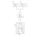
図1は、一実施形態に従う動的負荷管理のためのコンピュータデバイス100のブロック図の概略表示を図示する。この実施形態において、コンピュータデバイス100は、インターネットベース通信により充電ステーションの充電電流を制御することができる。 FIG. 1 illustrates a block diagram schematic representation of a
図1において、コンピュータデバイス100は、EVの少なくとも第1の充電ステーション108と、インターネットベース通信によるEVの少なくとも第2の充電ステーション110の充電電流を制御するように構成される。コンピュータデバイス100は、少なくとも1つのメモリ104と通信モジュール106に接続された少なくとも1つのプロセッサ102を備えることができる。少なくとも1つのコンピュータプログラムを備えることができ、このプログラムは、プロセッサ102または複数のプロセッサにより実行されると、コンピュータデバイス100にプログラムされた機能を実行させる。動的負荷管理動作114は、クラウドから供給することができる。少なくとも第1および少なくとも第2の充電ステーション108、110は、通信モジュール112を備え、コンピュータデバイス100は、通信モジュール112と通信するように構成することができる。充電ステーション108、110は、異なる製造業者からのものであり得る。充電ステーション108、110は、コンピュータデバイス100に無線で結合することができる。一実施形態によれば、充電ステーション108、110はコンピュータデバイス100とは異なるロケーションに配置することができる。充電ステーション108、110は、物理的なケーブルによってではなく、インターネットによって、コンピュータデバイスに無線で結合することができる。従って、ロケーションの距離は、かなり離れていてもよい。例えば、充電ステーション108、110は、同じビル内に、同じ街に、別の街に、あるいはコンピュータデバイスとは異なる国に位置していてもよい。 In FIG. 1, a
コンピュータデバイス100は、同時に充電しているEVsの数に基づいて、充電のための供給される最大電流を増加したり、あるいは減少したりすることにより第1の充電ステーション108と第2の充電ステーション110の充電電流を制御することができる。コンピュータデバイス100は、例えば、クラウドサーバあるいは分散システムであり得る。インターネットベースの通信は、オープンチャージポイントプロトコル(open charge point protocol)(OCPP)、オープンスマートチャージングプロトコル(OSCP)および/または充電ステーション製造業者固有のプロトコルを備えることができる。これは、充電電流を遠隔的に制御することを可能にし、それゆえ、追加のハードウェア、または新しい物理的インストレーションは必要ない。充電ステーション108、110は、あるベンダーまたはモデルに無関係であり得るので、EVs充電の電気需要は、より包括的に管理することができる。 The
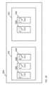
図2Aは、一実施形態に従う充電ステーションのグルーピングのブロック図の概略表示を図示する。充電ステーションは、複数のグループにグループ分けすることができ、さらにより大きなグループにグループに分けることができる。従って、充電容量は、異なるレベルでの制限を考慮することにより、より適切に管理することができる。 FIG. 2A illustrates a block diagram schematic representation of a grouping of charging stations according to one embodiment. Charging stations can be grouped into multiple groups and can be further grouped into larger groups. Therefore, charging capacity can be better managed by considering limits at different levels.
図2Aにおいて、コンピュータデバイス100は、さらにグループ202を決定するように構成され、各グループ202は、少なくとも1つの充電ステーション200を備え、少なくとも1つの充電ステーション200は、唯一のグループ202の一部であり得、各グループ202と各充電ステーション200のための最大電流を設定することにより充電電流を制御するように構成される。さらに、一に実施形態において、グループ202はサブグループであり得る。コンピュータデバイス100は、親グループ204を決定するように構成することができ、各親ブループ204は、少なくとも1つのサブグループ202を備え、各サブグループ202は、唯一の親グループ204の一部であり、各親グループ204のための最大電流を設定することにより充電電流を制御するように構成される。 In FIG. 2A,
各充電ステーション200は、IDと、各サブグループ202と各親グループ204は、充電ステーション200、サブグループ202および親グループ204を特定するための名前を持つことができる。例えば、サブグループ202は、そのロケーションにより名前をつけることができ、例えば、サブグループ202内のすべての充電ステーション200が位置するエリア内の地区または市の名前をつけることができる。 Each charging
一実施形態において、各親グループ204、各サブグループ202、および各充電ステーション200は、オリジナル最大電流と動的最大電流を備えることができる。オリジナル最大電流は、最大電流容量を備えることができる。動的最大電流は、充電EVsの数に依存することができる。オリジナル最大電流は、充電ステーション200、各サブグループ202または親グループ204が位置する背後にあるフューズサイズに基づいて設定することができ、あるいはオリジナル最大電流は、最大容量を決定するための他の基準に基づいて設定することができる。コンピュータデバイス100は、インターネットにより通信モジュールを介してオリジナル最大電流と動的最大電流を制御することができる。 In one embodiment, each
図2Bは、一実施形態に従う、充電ステーション200のグルーピングのブロック図の他の概略表示を図示する。図2Bは、どのようにして各サブグループ202が異なる数の充電ステーション200を備えることができるかを図示する。各サブグループ202は、少なくとも1つの充電ステーション200を備える。各充電ステーション200は、コンピュータデバイス100と通信するための通信モジュール112を備える。さらに、サブグループ203は、親グループ204の一部である。一実施形態において、親グループ204は、多数のサブグループ202を有することができ、1つのサブグループ202は、唯一の親グループ204を有することができる。さらに、他の実施形態において、親グループ204は、他の親グループ204の一部であり得、従って、親グループ204は、他の親グループ204にとってサブグループ202であり得る。コンピュータデバイス100は、より詳細に図3乃至7に図示するように、動的負荷管理の動作を実行するように構成することができる。 FIG. 2B illustrates another schematic representation of a block diagram of a grouping of charging
図3は、一実施形態に従う動的負荷管理のプロセス図の概略表示を図示する。コンピュータデバイス100は、アクティブ充電ステーション200についてのデータを記憶することができ、動的負荷管理のために充電EVsの数を追跡することができる。コンピュータデバイス100は、動作300において、EVを有するアクティブ充電ステーション200と、EVを有さない非アクティブ充電ステーション200についてのデータを記憶することができる。動作302において、充電開始または充電停止の少なくとも1つを要求する少なくとも1つの新しいEVについての情報が取得される。また、取得された情報は、要求している新しいEVを有する充電ステーション200のIDを備える。取得された情報に応答して、アクティブおよび非アクティブ充電ステーション200は動作304において更新される。更新されたデータに応答して、負荷調節は、動作306において決定される。 FIG. 3 illustrates a schematic representation of a process diagram of dynamic load management according to one embodiment.
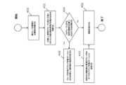
図4は、一実施形態に従う、新しい電気車両が充電の開始を要求したときの動的負荷管理のプロセス図の概略表示を図示する。図示プロセスは、少なくとも1つの新しいEVが充電ステーション200において充電の開始を要求すると、開始される。 FIG. 4 illustrates a schematic representation of a process diagram for dynamic load management when a new electric vehicle requests to start charging, according to one embodiment. The illustrated process begins when at least one new EV requests initiation of charging at charging
動作400において、親グループ204の負荷調節の必要性が判断される。調節の必要性が判断された場合、親グループ204により供給される新しい動的最大電流が、サブグループ内に、何らかの変更をする前に決定することができる。新しいEVがサブグループに加わった後で、サブグループ202内のEVs充電の数の決定が、動作402で行われる。 In
動作404において、サブグループ202において負荷調節の必要性が判断される。最初に、充電の開始を要求するEVを有する充電ステーション200が位置する、サブグループ202の現在の動的最大電流がチェックされる。その後、サブグループ202内の現在充電しているEVsを有するアクティブ充電ステーションの結合された動的最大電流を決定することが行われる。充電の開始を要求しているEVを有するアクティブ充電ステーション200の、現在の動的最大電流がチェックされる。現在充電しているEVsを有するアクティブ充電ステーション200の結合された動的最大電流と、充電の開始を要求するEVを有する充電ステーション200の、現在の動的最大電流がサブグループ202の現在の動的最大電流を超える場合、サブグループ202内のアクティブ充電ステーション200毎の新しい動的最大電流を決定することが、動作408において開始される。そうでなければ、新しい動的最大電流を設定する必要はなく、新しいEVが充電を開始することを可能にする確認が動作406において、送付される(dispatched)。 In
サブグループ202内のアクティブ充電ステーション毎の新しい動的最大電流の決定が、動作408において行われる。この決定はアクティブ充電ステーション200のオリジナル最大電流と、サブグループ202のアクティ充電ステーション200間のサブグループ202の均一に分割された動的最大電流との比較により行われる。次に、アクティブ充電ステーション毎に、より低い値を有する最大電流が選択される。動作408における決定に基づいて、動作410において、新しい動的最大電流がアクティブ充電ステーション200毎に設定される。サブグループ202内のアクティブ充電ステーション200毎の新しい動的最大電流が設定された後に、新しいEVが充電を開始することができるように、確認が動作408において送付される。 Determination of a new dynamic maximum current for each active charging station in
図5は、一実施形態に従う、新しい電気車両が充電を停止することを要求したときの動的負荷管理のプロセス図の概略表示を図示する。図示プロセスは、充電ステーション200において、充電を停止することを、少なくとも1つの新しいEVが要求すると、開始される。動作500において、充電を停止することを要求している、少なくとも1つの新しいEVについての情報が取得される。次に、動作502において、少なくとも1つの新しいEVが充電を停止した後で、サブグループ202内のEVs充電の数が判断される。 FIG. 5 illustrates a schematic representation of a process diagram for dynamic load management when a new electric vehicle requests to stop charging, according to one embodiment. The illustrated process begins when at least one new EV requests to stop charging at charging
動作504において、サブグループ202内に何らのアクティブ充電ステーション200も無い場合、動作506において、親グループ204の調節の必要性の判断が行われる。少なくとも1つのEVが充電を停止した後で、サブグループ202内に少なくとも1つのアクティブ充電ステーション200がある場合、動作408において、新しい動的最大電流が、サブグループ202内のアクティブ充電ステーション200毎に決定される。サブグループ202内のアクティブ充電ステーション200毎に新しい動的最大電流を決定することは、動作408において行われる。この決定は、アクティブ充電ステーション200のオリジナル最大電流と、サブグループ202のアクティブ充電ステーション間の均一に分割された動的最大電流を比較することにより行われる。次に、アクティブ充電ステーション毎に、より低い値を有する最大電流が選択される。動作408における決定に基づいて、動作410において、新しい動的最大電流がアクティブ充電ステーション200毎に行われる。その後、親グループ204の調節の必要性が、動作400において判断される。 If in
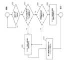
図6は、一実施形態に従う、負荷調節の必要性が親グループ204内において判断される動的負荷管理のプロセス図の概略表示を図示する。図示プロセスは、図4および図5の動作400に応答する。動作600において、グループが別の親グループ204に属するか否かが判断される。グループが別の親グループ204に属さない場合、動作602に進む。 FIG. 6 illustrates a schematic representation of a process diagram of dynamic load management in which the need for load adjustment is determined within a
動作602において、要求しているEVを有するサブグループが、以前は空であったが、今はEV充電を有するかどうかが判断される。そうでなければ、動作604において、以前は、サブグループ202においてEV充電があったが、今は空であるかどうかが判断される。そうでなければ、動作606において調節の必要性はなく、動的最大電流は変わらない。 In
そうでなければ、動作608に進み、少なくとも1つのアクティブ充電ステーション200に関連するサブグループ202毎に、新しい動的最大電流を決定する。この決定は、少なくとも1つのアクティブ充電ステーション200に関連する、各サブグループのオリジナル最大電流と、アクティブ充電ステーション200に関連するサブグループ202間の親グループ204の均一に分割された動的最大電流を、比較することを備える。比較の後、低い値を有する最大電流は、少なくとも1つのアクティブ充電ステーション200に関連する各サブグループ202に対して選択される。動作608における判断に基づいて、動作610において、少なくとも1つのアクティブ充電ステーション200に関連するサブグループ202毎に、新しい動的最大電流が設定される。 Otherwise, proceed to
図7は、他の実施形態に従う、新しい最大電流が階層構造において決定される動的負荷管理のプロセス図の概略表示を図示する。任意のグループの動的最大電流が変更された後、グループのサブグループのための、あるいは、グループのアクティブ充電ステーションのための、新しい動的最大電流が決定される。それゆえ、グループは状況に応じて、親グループまたはサブグループのいずれかを指す。動作608および408は、図4乃至6の記述において詳細に記載したものに相当するので、次のセクションでは省略される。 FIG. 7 illustrates a schematic representation of a process diagram of dynamic load management in which a new maximum current is determined in a hierarchical structure, according to another embodiment. After the dynamic maximum current for any group is changed, new dynamic maximum currents for subgroups of the group or for active charging stations of the group are determined. Therefore, a group refers to either a parent group or a subgroup, depending on the context.
動作700において、グループの新しい動的最大電流は、充電を開始または停止するための少なくとも1つの新しいEVの要求により開始される決定に基づいて設定される。グループが少なくとも1つのサブグループ202を有する場合、少なくとも1つのサブグループ202に対する新しい動的最大電流が動作608において決定される。グループが少なくとも1つのサブグループ202を有さない場合、動作408において、新しい動的最大電流が、アクティブ充電ステーションに対して決定される。次に、グループの異なるレベルでの動的負荷管理のプロセスと、レベルの構造が以下により詳細に記載される。図8乃至15に図示するように、コンピュータデバイス100は、グループを決定するように、およびグループと充電ステーションの動的最大電流を制御するように構成することができる。EVsに供給された最大電流は、それらの数に応じて動的に制御することができるので、サプライネットワークの容量を超えることなく、各EVに対する最大充電電力を供給することが可能である。 In
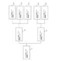
図8は、一実施形態に従う、グループの階層構造のブロック図の概略表示を図示する。
グループの図示階層構造は、1つの可能性に過ぎない。多かれ少なかれ、異なるレベルのグループがあり、また、オリジナル最大電流は、決定に基づいて異なり得る。「グループ」という用語は、同じグループが両方になる可能性があるため、捉えかたによって親グループ、またはサブグループのいずれかを指すことができる。図8は、いずれの充電ステーションにもEVs充電が無いときの動的負荷管理の開始状況を図示する。グループA11、A12、A13、A21、A22の各々は、少なくとも1つの充電ステーション(図8には図示せず)を備え、各充電ステーションは、唯一のグループの一部である。さらに、グループA11、A12、A13はグループA1にグループ分けされる。それゆえ、グループA11、A12、A13はグループA1のサブグループであり、グループAは、グループA11、A12、A13の親グループである。同様に、グループA21、A22はグループA2としてグループ分けされる。それゆえ、グループA21、A22は、グループA2のサブグループであり、グループA2は、グループA21、A22のための親グループである。さらに、グループA1、A2は、グループAのサブグループであり、グループAは、グループA1、A2の親グループである。FIG. 8 illustrates a block diagram schematic representation of a hierarchical structure of groups, according to one embodiment.
The illustrated hierarchy of groups is only one possibility. There are more or less groups of different levels, and also the original maximum current may be different based on the decision. The term "group" can refer to either a parent group or a subgroup, depending on how you interpret it, since the same group can be both. FIG. 8 illustrates the starting situation of dynamic load management when there are no EVs charging at any charging station. Each of the groups A11, A12, A13, A21, A22 comprises at least one charging station (not shown in FIG. 8), and each charging station is part of only one group. Furthermore, groups A11, A12, and A13 are grouped into group A1. Therefore, groups A11, A12, A13 are subgroups of group A1, and group A is the parent group of groups A11, A12, A13. Similarly, groups A21 and A22 are grouped as group A2. Therefore, groups A21, A22 are subgroups of group A2, and group A2 is a parent group for groups A21, A22. Further, groups A1 and A2 are subgroups of group A, and group A is a parent group of groups A1 and A2.
各親グループは、少なくとも1つのサブグループを備えることができ、各サブグループは、唯一の親グループの一部であり得る。例えば、グループA2は、グループA13を備えることができない。なぜならば、A13はすでに、グループAの一部だからである。各グループは、オリジナル最大電流と動的最大電流を備えることができる。オリジナル最大電流は、各充電電流と各グループの最大電流容量であり得る。動的最大電流は、充電EVsの数に依存することができる。充電するEVsが無いとき、動的最大電流は、オリジナル最大電流と同じ値を持つことができる。 Each parent group may include at least one subgroup, and each subgroup may be part of only one parent group. For example, group A2 cannot include group A13. This is because A13 is already part of group A. Each group can include an original maximum current and a dynamic maximum current. The original maximum current can be the maximum current capacity of each charging current and each group. The dynamic maximum current may depend on the number of charging EVs. When there are no EVs to charge, the dynamic maximum current can have the same value as the original maximum current.
図9は、他の実施形態に従う、新しい電気車両が充電を開始することを要求するときのグループの階層における動的負荷管理のブロック図の概略表示を図示する。図9乃至15において、グループは、少なくとも1つのアクティブ充電ステーションを備え、さらに、少なくとも1つのアクティブ充電ステーションに関連する親グループを備えるグループが実線で図示される。そのときに負荷がアクティブになっていないグループは、破線で図示される。簡単化のために、充電ステーションは、図9乃至14には示されていない。各充電ステーションは、32Aのオリジナル最大電流を有すると推定され、32Aは、図9乃至15に図示される例においてEVsの最大充電電流である。 FIG. 9 illustrates a block diagram schematic representation of dynamic load management in a hierarchy of groups when a new electric vehicle requests to start charging, according to another embodiment. In FIGS. 9-15, groups are illustrated in solid lines that include at least one active charging station and further include a parent group that is associated with the at least one active charging station. Groups for which no load is active at the time are illustrated with dashed lines. For simplicity, charging stations are not shown in FIGS. 9-14. Each charging station is estimated to have an original maximum current of 32A, where 32A is the maximum charging current of the EVs in the examples illustrated in FIGS. 9-15.
図9において、新しいEV1は、充電を開始することを要求している。この要求に応答して、負荷が調節を必要とするか否かの判断が開始される。EV1が充電を開始することを要求している充電ステーションは、グループA11に含まれる。調節の必要性がグループA11と充電ステーションに対して判断する前に、調節の必要性は、親グループに対して判断される。アクティブ充電ステーションの数は、親グループA1、Aの観点からサブグループ内で変更になったので、新しい最大電流の決定が開始される。新しい動的最大電流は、新しいEVを有する充電ステーションに対して決定されるとともに、アクティブ充電ステーションに関連する各グループに対して決定される。親グループAの動的最大電流は、少なくとも1つのアクティブ充電ステーションに関連するサブグループ間で均一に分割される。グループA1のみがアクティブ充電ステーションに関連しているので、親グループAの全体の動的最大電流は、グループA1に供給される。グループA1のオリジナル最大電流は、供給された最大電流よりも低いので、グループA1のオリジナル最大電流は、新しい動的最大電流として設定される。さらに、グループA1の動的最大電流は、少なくとも1つのアクティブ充電ステーションを有するグループA1のサブグループ間で均一に分割される。ここで、サブグループA11のみがアクティブ充電ステーションを有するので、親グループA1の全体の動的最大電流は、サブグループA11に対して供給される。サブグループA11のオリジナル最大電流は、供給された最大電流よりも低いので、サブグループA11のオリジナル最大電流は、新しい動的最大電流として設定される。グループA11内には、他のアクティブ充電ステーションは無く、EV1を有する充電ステーションの現在の動的最大電流は、グループA11の新しい動的最大電流よりも低いので、調節する必要はなく、EV1は最大容量で充電される。 In Figure 9, the new EV1 is requesting to start charging. In response to this request, a determination is initiated whether the load requires adjustment. The charging station that EV1 requests to start charging is included in group A11. Before the need for adjustment is determined for group A11 and the charging station, the need for adjustment is determined for the parent group. Since the number of active charging stations has changed within the subgroup from the point of view of the parent group A1,A, a new maximum current determination is initiated. A new dynamic maximum current is determined for charging stations with new EVs and for each group associated with active charging stations. The dynamic maximum current of parent group A is divided evenly among subgroups associated with at least one active charging station. Since only group A1 is associated with active charging stations, the entire dynamic maximum current of parent group A is supplied to group A1. Since the original maximum current of group A1 is lower than the supplied maximum current, the original maximum current of group A1 is set as the new dynamic maximum current. Furthermore, the dynamic maximum current of group A1 is evenly divided among subgroups of group A1 having at least one active charging station. Here, since only subgroup A11 has an active charging station, the entire dynamic maximum current of parent group A1 is supplied to subgroup A11. Since the original maximum current of subgroup A11 is lower than the supplied maximum current, the original maximum current of subgroup A11 is set as the new dynamic maximum current. There are no other active charging stations in group A11, and the current dynamic maximum current of the charging station with EV1 is lower than the new dynamic maximum current of group A11, so there is no need to adjust and EV1 is at maximum It is charged with capacity.
図10は、一実施形態に従う、他の新しい電気車両が充電を開始することを要求したときのグループの階層における、動的負荷管理のブロック図の概略表示を図示する。EVsの数が増加するにつれ、コンピュータデバイス100はネットワークの充電容量がバランスされていることを保証するように最大電流を制御する。 FIG. 10 illustrates a block diagram schematic representation of dynamic load management in a hierarchy of groups when another new electric vehicle requests to start charging, according to one embodiment. As the number of EVs increases,
図10において、1つのEV1充電があり、新しいEV2が充電を開始することを要求している。EV2を有するアクティブ充電ステーションは、グループA13に含まれ、A13は、アクティブ充電ステーションを有する他のグループA11と同じ親グループの一部である。それゆえ、少なくとも1つのアクティブ充電ステーションに関連するサブグループの数は、親グループAから見ると変更されておらず、調節は必要ない。グループA1から見ると、少なくとも1つのアクティブ充電ステーションを有するサブグループの数は、変更され、グループA1は、少なくとも1つのアクティブ充電ステーションを有する2つのサブグループA11、A13を有する。従って、負荷は、サブグループに対して調節する必要がある。親グループA1の動的最大電流は、少なくとも1つのアクティブ充電ステーションに関するサブグループA11、A13の間で均一に分割される。このため、サブグループA11、A13に対する分割された動的最大電流は、それらのオリジナル最大電流よりも低いので、親グループA1の分割された動的最大電流は、各サブグループA11、A13に対する新しい動的最大電流として設定される。サブグループA11、A13内には、他のアクティブ充電ステーションはなく、EVs1、2を有する充電ステーションの現在の動的最大電流は、サブグループA11、A13の新しい動的最大電流よりも低いので、調節の必要はなく、EVs1,2は、最大容量で充電される。 In Figure 10, there is one EV1 charging and a new EV2 is requesting to start charging. The active charging station with EV2 is included in group A13, which is part of the same parent group as the other group A11 with active charging stations. Therefore, the number of subgroups associated with at least one active charging station is unchanged from the parent group A and no adjustment is required. From the point of view of group A1, the number of subgroups with at least one active charging station is changed, and group A1 has two subgroups A11, A13 with at least one active charging station. Therefore, the load needs to be adjusted for subgroups. The dynamic maximum current of the parent group A1 is evenly divided between the subgroups A11, A13 for at least one active charging station. Therefore, the split dynamic maximum currents for subgroups A11, A13 are lower than their original maximum currents, so the split dynamic maximum currents for parent group A1 are lower than the new dynamic maximum currents for each subgroup A11, A13. set as the target maximum current. There are no other active charging stations in the subgroups A11, A13, and the current dynamic maximum current of the charging stations with EVs1, 2 is lower than the new dynamic maximum current of the subgroups A11, A13, so the adjustment There is no need for EVs1 and EVs2 to be charged at their maximum capacity.
図11は、他の実施形態に従う、他の新しい電気車両が、充電を開始することを要求したときの、グループの階層における動的負荷管理のブロック図の概略表示を図示する。EVsの数はさらに増えるので、コンピュータデバイス100は、ネットワークの充電容量がバランスされることを保証するように最大電流を制御する。 FIG. 11 illustrates a block diagram schematic representation of dynamic load management in a hierarchy of groups when another new electric vehicle requests to start charging, according to another embodiment. As the number of EVs increases further, the
図11において、2つのEVs1、2の充電があり、新しいEV3が充電を開始することを要求している。EV2を有するアクティブ充電ステーションは、グループA13に属し、A13は、EVs1、3を有する2つのアクティブ充電ステーションを有する他のグループA11と同じ親グループの一部である。それゆえ、少なくとも1つのアクティブ充電ステーションに関連するサブグループの数は、親グループAからみると変更されておらず、そのサブグループに対して調節する必要はない。また、グループA1から見ると、少なくとも1つのアクティブ充電ステーションを有するサブグループの数は変わらないので調節する必要はない。しかしながら、アクティブ充電ステーションの数は、グループA11内で変更され、かつ現在充電しているEV1を有する充電ステーションと、要求しているEV3を有する充電ステーションの、結合された動的最大電流の値は、グループA11の動的最大電流の値より大きいので、電力は、そのグループの動的最大電流内に調節する必要がある。グループA11の動的最大電流は、2つのアクティブ充電ステーション間で均一に分割され、各アクティブ充電ステーションのオリジナル最大電流と、グループA11の分割された動的最大電流の比較に基づいて、新しい動的最大電流が、各アクティブ充電ステーションに設定され、より低い値を有する最大電流が、各アクティブ充電ステーションに対する新しい動的最大電流として選択される。この場合、グループA11の均一に分割された動的最大電流は、偶数ではないので、この値は丸められ、丸められた値が新しい動的最大電流として設定される。 In FIG. 11, there are two EVs1, 2 charging and a new EV3 requests to start charging. The active charging station with EV2 belongs to group A13, which is part of the same parent group as another group A11 with two active charging stations with EVs1,3. Therefore, the number of subgroups associated with at least one active charging station is unchanged from the parent group A and does not need to be adjusted for that subgroup. Also, from the perspective of group A1, the number of subgroups with at least one active charging station remains the same and therefore does not need to be adjusted. However, the number of active charging stations has changed within group A11, and the value of the combined dynamic maximum current of the charging station with the currently charging EV1 and the charging station with the requesting EV3 is , is larger than the value of the dynamic maximum current of group A11, so the power needs to be adjusted within the dynamic maximum current of that group. The dynamic maximum current of group A11 is divided uniformly between the two active charging stations, and a new dynamic A maximum current is set for each active charging station, and the maximum current with the lower value is selected as the new dynamic maximum current for each active charging station. In this case, since the uniformly divided dynamic maximum current of group A11 is not an even number, this value is rounded and the rounded value is set as the new dynamic maximum current.
図12は、他の実施形態に従う、他の新しい電気車両が充電を開始することを要求したときのグループの階層における動的負荷管理のブロック図の概略表示を図示する。EVsの数はさらに増えたので、コンピュータデバイス100は、ネットワークの充電容量がバランンスされるのを保証するように最大電流を制御する。 FIG. 12 illustrates a block diagram schematic representation of dynamic load management in a hierarchy of groups when another new electric vehicle requests to start charging, according to another embodiment. As the number of EVs increases further, the
図12において、3つのEVs1、2,3充電があり、新しいEV4は、充電を開始することを要求している。EV2を有するアクティブ充電ステーションは、グループA13に属し、A13は、EVs1、3を有する2つのアクティブ充電ステーションを有するグループA11と同じ親グループA1の一部である。さらに、グループA21の一部である充電ステーションにおいて充電を開始するように要求し、親グループAのさらなる一部である親グループA2に関連する新しいEV4がある。それゆえ、親グループAから見て少なくとも1つのアクティブ充電ステーションに関連するサブグループの数は変更され、負荷を調節する必要がある。このため、親グループAの動的最大電流は、両方とも少なくとも1つのアクティブ充電ステーションに関連する、サブグループA1とサブグループ2との間で分割される。各サブグループA1、A2に対する新しい動的最大電流は、それらのオリジナル最大電流を、親グループAの分割された動的最大電流と比較することにより決定され、より低い値を有する動的最大電流を、新しい動的最大電流として設定する。グループA1、A2は両方ともサブグループを有するので、少なくとも1つのアクティブ充電ステーションを有するサブグループA1、A2の動的最大電流もまた調節される。 In Figure 12, there are three EVs1, 2, 3 charging, and a new EV4 is requesting to start charging. The active charging station with EV2 belongs to group A13, which is part of the same parent group A1 as group A11 with two active charging stations with EVs1,3. Furthermore, there is a new EV4 that requests to start charging at a charging station that is part of group A21 and is associated with parent group A2 that is further part of parent group A. Therefore, the number of subgroups associated with at least one active charging station from the perspective of the parent group A is changed and the load needs to be adjusted. Therefore, the dynamic maximum current of parent group A is divided between subgroup A1 and
親グループA1の新しい動的最大電流は、両方が少なくとも1つのアクティブ充電ステーションを有するサブグループA11とA13に均一に分割される。分割された動的充電電流はA11、A13の各々のオリジナル最大電流と比較され、より低い値を有する動的最大電流を選択することにより、新しい動的最大電流が比較に基づいて設定される。その後、少なくとも1つのアクティブ充電ステーションを有するグループ内で負荷が調節を必要とするか否かが判断される。サブグループA11において、アクティブ受電ステーションの結合された動的最大電流の値が、グループA11の動的最大電流より大きいので、新しい動的最大電流が、アクティブ充電ステーションに対して決定される。この場合、EVs1および3を有する2つの充電ステーション間におけるサブグループA11の均一に分割された最大電流は、充電ステーションのオリジナル最大電流よりも低いので、均一に分割された動的最大電流が、それらの新しい動的最大電流として設定される。サブグループA13において、ただ1つのEV2充電があり、アクティブ充電ステーションの動的最大電流は、サブグループA13の動的最大電流より低いので、調節する必要はない。 The new dynamic maximum current of the parent group A1 is evenly divided into subgroups A11 and A13, both of which have at least one active charging station. The divided dynamic charging current is compared to the original maximum current of each of A11, A13, and a new dynamic maximum current is set based on the comparison by selecting the dynamic maximum current with the lower value. It is then determined whether a load requires adjustment within the group having at least one active charging station. In subgroup A11, the value of the combined dynamic maximum current of the active power receiving stations is greater than the dynamic maximum current of group A11, so a new dynamic maximum current is determined for the active charging stations. In this case, the uniformly divided maximum current of subgroup A11 between the two charging stations with EVs1 and 3 is lower than the original maximum current of the charging stations, so the uniformly divided dynamic maximum current between them is set as the new dynamic maximum current. In subgroup A13, there is only one EV2 charging and the dynamic maximum current of the active charging station is lower than the dynamic maximum current of subgroup A13, so there is no need to adjust.
親グループA2は、今、新しい動的充電電流を有しているので、新しい動的充電電流が、少なくとも1つのアクティブ充電ステーションに関連するサブグループに対しても決定される。この場合、サブグループA21のみがEV4を有するアクティブ充電ステーションを有する。従って、グループA2のすべての動的最大電流が、サブグループA21に供給される。供給された動的最大電流は、サブグループA21のオリジナル最大電流と比較され、より低い値を有する最大電流が、新しい動的最大電流として設定される。要求しているEV4を有するアクティブ充電ステーション以外に、サブグループA21には、他のアクティブ充電ステーションはなく、充電ステーションのオリジナル最大電流は、サブグループA21の動的最大電流より低いので、調節する必要はなく、EV4には最大電流容量が供給される。 Since the parent group A2 now has a new dynamic charging current, new dynamic charging currents are also determined for the subgroups associated with at least one active charging station. In this case, only subgroup A21 has an active charging station with EV4. Therefore, all dynamic maximum currents of group A2 are supplied to subgroup A21. The supplied dynamic maximum current is compared with the original maximum current of subgroup A21, and the maximum current with the lower value is set as the new dynamic maximum current. Other than the active charging station with the requesting EV4, there are no other active charging stations in subgroup A21, and the original maximum current of the charging station is lower than the dynamic maximum current of subgroup A21, so it needs to be adjusted. EV4 is supplied with the maximum current capacity.
図13は、他の実施形態に従う、新しい電気車両が、充電を停止することを要求したときのグループの階層内における動的負荷管理のブロック図の概略表示を図示する。今、EVsの数は減少するので、コンピュータデバイス100は、ネットワークの充電容量がバランスされるのを保証するように動的最大電流を制御する。EVsの全体数が減少すると、変更する容量に応じて、より多くの充電電力をいくつかのEVsに供給することができる。 FIG. 13 illustrates a block diagram schematic representation of dynamic load management within a hierarchy of groups when a new electric vehicle requests to stop charging, according to another embodiment. Now, as the number of EVs decreases, the
図13において、EVsの1つであるEV2が、充電を停止するよう要求している。この結果、グループA13は、これ以上何らのアクティブ充電ステーションを有さず、かつ、親グループA1から見ると、少なくとも1つのアクティブ充電ステーションに関連するサブグループの数が変更されたので、負荷を調節する必要がある。親グループA1のすべての動的最大電流が、少なくとも1つのアクティブ充電電流を有するグループA11にのみ供給される。供給された動的最大電流は、サブグループA11のオリジナル最大電流より大きいので、より低い値を有するオリジナル最大電流が、新しい最大電流として設定される。この結果、サブグループA11内のアクティブ充電ステーションに対して、新しい動的最大電流が決定される。車両1、3を有するアクティブ充電ステーションに対して、サブグループA11の動的最大電流が均一に分割され、アクティブ充電ステーションのオリジナル最大電流と比較される。この結果、分割された動的最大電流は、各アクティブ充電ステーションのオリジナル最大電流よりも低い値を有するので、分割された動的最大電流は、アクティブ充電ステーションに対する新しい動的最大電流として設定される。グループA21においては、アクティブ充電ステーションの数は変更されず、親グループA2、Aの少なくとも1つのアクティブ充電ステーションに関連するサブグループの数も変化しないので、このグループに対して負荷調節の必要はないと判断される。 In FIG. 13, one of the EVs, EV2, requests to stop charging. As a result, group A13 no longer has any active charging stations, and from the perspective of parent group A1, the number of subgroups associated with at least one active charging station has changed, so the load is adjusted. There is a need to. All dynamic maximum currents of the parent group A1 are supplied only to the group A11 that has at least one active charging current. Since the supplied dynamic maximum current is greater than the original maximum current of subgroup A11, the original maximum current with the lower value is set as the new maximum current. As a result, a new dynamic maximum current is determined for the active charging stations in subgroup A11. For active charging stations with
図14は、他の実施形態に従う、他の新しい電気車両が充電の停止を要求したときのグループの階層における動的負荷管理のブロック図の概略表示を図示する。コンピュータデバイス100は、充電EVsの数が変化したことに応答して負荷を調節することができる。 FIG. 14 illustrates a block diagram schematic representation of dynamic load management in a hierarchy of groups when another new electric vehicle requests to stop charging, according to another embodiment.
図14において、EV4は充電を停止するように要求している。それゆえ、グループA2内には、もはや何らのアクティブ充電ステーションもなく、親グループAから見ると、少なくとも1つのアクティブ充電ステーションに関連するサブグループの数は、変化したので、負荷を調節する必要がある。今、グループA1は、少なくとも1つのアクティブ充電ステーションに関連する唯一のサブグループであるので、親グループAの動的最大電流は、サブグループA1に対して供給される。グループA1のオリジナル最大電流は、より低い値を有するので、オリジナル最大電流は、グループA1に対する新しい動的最大電流として設定される。さらに、新しい動的最大電流は、アクティブ充電ステーションを有する、A1の唯一のサブグループA11に対して決定される。この場合にも、少なくとも1つのアクティブ充電ステーションを有する他のサブグループはないので、グループA1の動的最大電流のすべてがサブグループA11に供給される。サブグループA11のオリジナル最大電流は、より低い値を有するので、オリジナル最大電流は、新しい動的最大電流として設定される。グループA11内のアクティブ充電ステーションの結合された動的最大電流は、グループA11の動的最大電流を超えないので、さらに負荷を調節する必要はない。 In FIG. 14, EV4 requests to stop charging. Therefore, within group A2 there are no longer any active charging stations, and from the perspective of the parent group A, the number of subgroups associated with at least one active charging station has changed, so the load needs to be adjusted. be. Since group A1 is now the only subgroup associated with at least one active charging station, the dynamic maximum current of parent group A is supplied to subgroup A1. Since the original maximum current of group A1 has a lower value, the original maximum current is set as the new dynamic maximum current for group A1. Furthermore, a new dynamic maximum current is determined for the only subgroup A11 of A1 with active charging stations. Again, all of the dynamic maximum current of group A1 is supplied to subgroup A11 since there is no other subgroup with at least one active charging station. Since the original maximum current of subgroup A11 has a lower value, the original maximum current is set as the new dynamic maximum current. Since the combined dynamic maximum current of the active charging stations in group A11 does not exceed the dynamic maximum current of group A11, no further load adjustment is required.
図15は、一実施形態に従う、他の新しい電気車両が充電を停止することを要求したときのグループの階層における動的負荷管理のブロック図の概略表示である。コンピュータデバイス100は、充電EVsの数が変化したことに応答して負荷を調節することができ、残りのEVに対して利用可能な最大電流を供給する。 FIG. 15 is a block diagram schematic representation of dynamic load management in a hierarchy of groups when another new electric vehicle requests to stop charging, according to one embodiment.
図15において、EV3は充電を停止することを要求している。少なくとも1つの充電ステーションを有するグループの数に変化があるので、グループA11内の充電電力のみ、調節する必要がある。今、グループA11には、唯一のアクティブ充電ステーションがあるので、動的最大電流のすべてが、1つのアクティブ充電ステーションに供給される。供給された動的最大電流は、アクティブ充電電流のオリジナル最大電流より大きいので、オリジナル最大電流は、新しい動的最大電流として設定され、EV1に供給される充電電流は増大する。 In FIG. 15, EV3 requests to stop charging. Since there is a change in the number of groups with at least one charging station, only the charging power within group A11 needs to be adjusted. There is now only one active charging station in group A11, so all of the dynamic maximum current is supplied to one active charging station. Since the supplied dynamic maximum current is greater than the original maximum current of the active charging current, the original maximum current is set as the new dynamic maximum current and the charging current supplied to EV1 is increased.
ここに記載された機能は、少なくとも一部が、ソフトウエアコンポーネントのような1つまたは複数のコンピュータプログラムにより行うことができる。ここに記載された任意のレンジまたはデバイス値は、求めている効果を失うことなく、拡張または変更することができる。また、明示的に不可能でない限り、任意の実施形態を他の実施形態と組み合わせることができる。 The functions described herein can be performed, at least in part, by one or more computer programs, such as software components. Any range or device value described herein can be extended or modified without losing the desired effect. Also, any embodiment may be combined with other embodiments unless expressly not possible.
この発明の主題が構造的特徴および/または行為に特有の言語で記載されたけれども、添付された請求項に定義された主題は、必ずしも上述した特定の特徴、または行為に限定されないことが理解される。むしろ、上述した特定の特徴と行為は、請求項をインプリメントする例として開示され、他の均等な特徴および行為は特許請求の範囲内にあることを意図している。 Although the subject matter of this invention has been described in language specific to structural features and/or acts, it is to be understood that the subject matter defined in the appended claims is not necessarily limited to the specific features or acts described above. Ru. Rather, the specific features and acts described above are disclosed as examples of implementing the claims, and other equivalent features and acts are intended to be within the scope of the claims.
上述した利益および利点は、一実施形態に関連することができ、あるいはいくつかの実施形態に関連することができることが理解されるであろう。この実施形態は、上述した問題のいずれか、またはすべて、または上述した利益および利点のいずれか、またはすべてを有する実施形態に限定されない。「1つの」アイテムへの言及は、1つまたは複数のアイテムを指すことをさらに理解されたい。「および/または」という用語は、それが関連する1つまたは複数のケースを生じ得ることを示すために使用されることができる。両方、あるいはそれ以上の関連するケースが生じてもよいし、あるいは関連するケースのいずれか1つのみが生じてもよい。 It will be appreciated that the benefits and advantages described above may relate to one embodiment or may relate to several embodiments. This embodiment is not limited to embodiments having any or all of the problems described above or any or all of the benefits and advantages described above. It should be further understood that references to "an" item refer to one or more items. The term "and/or" can be used to indicate that it may give rise to one or more related cases. Both or more relevant cases may occur, or only one of the relevant cases may occur.
ここに記載した方法のステップは任意の適切な順番で実行することができ、あるいは適切である場合には、同時に実行することができる。さらに、個々のブロックは、ここに記載した主題の精神と範囲から逸脱することなく、任意の方法から削除することができる。上述した実施形態のいずれかの態様は、他の実施形態のいずれかの態様と結合して、求められた効果を失うことなくさらなる実施形態を形成することができる。用語「備える」は、ここでは、特定した方法、ブロックまたはエレメントを含むことを意味するが、そのようなブロックまたはエレメントは、排他リストを含まず、方法または装置は、さらなるブロックまたはエレメントを含むことができる。 The steps of the methods described herein can be performed in any suitable order or, where appropriate, simultaneously. Additionally, individual blocks may be deleted in any manner without departing from the spirit and scope of the subject matter described herein. Any aspect of the embodiments described above may be combined with any aspect of other embodiments to form further embodiments without losing the desired effect. The term "comprising" as used herein is meant to include the specified method, block or element, but does not include an exclusive list of such blocks or elements, and does not imply that the method or apparatus includes further blocks or elements. I can do it.
上述した記載は、例示として与えられたものに過ぎず、当業者によって種々の変更が可能であることが理解されよう。上記仕様、例およびデータは、例示実施形態の構造および使用の完全な記述を提供する。さまざまな実施形態についてある程度の特殊性をもって、あるいは1つ以上の個々の実施形態を参照して上述したが、当業者は、この明細書の精神および範囲から逸脱することなく、ここに開示した実施形態に対して様々な変更をすることが可能である。
It will be understood that the above description is given by way of example only and that various modifications may be made by those skilled in the art. The above specifications, examples, and data provide a complete description of the structure and use of example embodiments. Although various embodiments have been described above with some specificity or with reference to one or more individual embodiments, those skilled in the art will appreciate that the embodiments disclosed herein can be modified without departing from the spirit and scope of this specification. Various changes to the form are possible.
Claims (10)
Translated fromJapanese前記第1および第2の充電ステーションが備える通信モジュールと、前記充電ステーション間のインターネット通信に基づいて、かつ前記充電ステーションの異なる製造業者が提供する製造業者固有のプロトコルを備えた通信に基づいて、通信するように構成され、
前記異なる製造業者の前記充電ステーション(200、108、110)と無線で結合されて、前記通信に基づいて、前記充電ステーション(200、108、110)の前記充電電流を制御するように構成され、
サブグループ(202、204、A1、A2、A11、A12、A13、A21、A22)を決定し、各サブグループは少なくとも1つの充電ステーションを備え、各充電ステーションは、1つのサブグループに属し、
親グループ(204、202、A、A1、A2)を決定し、各親グループ(204、202、A、A1、A2)は、少なくとも1つのサブグループ(204、202、A1、A2、A11、A12、A13、A21、A22)を備え、各サブグループ(204、202、A1、A2、A11、A12、A13、A21、A22)は1つの親グループ(204、202、A、A1、A2)に属し、
各充電ステーション(200、108、110)、各サブグループ(204、202、A1、A2、A11、A12、A13、A21、A22)および各親グループ(204、202、A、A1、A2)は、オリジナル最大電流と動的最大電流を有し、前記オリジナル最大電流は、最大電流容量を含み、前記動的最大電流は、充電している電気車両の数に依存し、
各充電ステーション、各サブグループおよび各親グループに関して、前記動的最大電流が、前記オリジナル最大電流を超えないように、前記動的最大電流をセットすることにより充電電流を制御するように構成され、
前記電気車両を有するアクティブ充電ステーション(200、108、110)と、電気車両を有さない非アクティブ充電ステーション(200、108、110)についてのデータを記憶し(300)、
充電の開始または充電の停止の少なくとも1つを要求している、少なくとも1つの新しい電気車両(1、2、3、4)と、要求している新しい電気車両(1、2、3、4)を有する電気充電ステーション(200、108、110)のアイデンティティについての情報を取得し(302)、
アクティブおよび非アクティブ充電ステーション(200、108、110)についてのデータを更新し(304、402、502)、
前記更新されたデータに応答して、負荷調節の必要性を判断することを開始し(306、400、404、506、608、704)、
前記判断に応答して前記要求の確認を送付する(406)、
ようにさらに構成され、
前記負荷調節の必要性を判断する(306)ことは、
前記新しい電気車両(1、2、3、4)が充電を停止すること(500)を要求した、グループ(202、A11、A12、A13、A21、A22)内に少なくとも1つのアクティブ充電ステーション(200、108、110)が残されているかどうかをチェックする(502、504)ことと、
前記グループ(202、A11、A12、A13、A21、A22)に残された前記アクティブ充電ステーション(200、108、110)のための新しい動的最大電流の決定を開始することと、
新しい動的最大電流を決定すること(408、508、706)は、
前記アクティブ充電ステーション(200、108、110)の前記オリジナル最大電流と、前記グループ(202、A11、A12、A13、A21、A22)の前記アクティブ充電ステーション(200、108、110)間の、前記グループ(202、A11、A12、A13、A21、A22)の均一に分割された動的最大電流を比較し、各アクティブ充電ステーション(200、108、110)に対して、より低い値を有する前記動的最大電流を選択することと、
前記決定に基づいて、各アクティブ充電ステーション(200、108、110)に対して、前記新しい動的最大電流を設定する(410、510、706)ことと、
を特徴とする、コンピュータデバイス(100)。A computing device (100) for controlling charging current of a first charging station (200, 108) of at least one electric vehicle and a second charging station (200, 110) of at least one electric vehicle through Internet-based communications. adjusting and determining the charging current load in response to at least one electric vehicle requesting to start or stop charging;
based on communication modules provided by the first and second charging stations and Internet communication between the charging stations and with manufacturer-specific protocols provided by different manufacturers of the charging stations; configured to communicate;
wirelessly coupled to the charging station (200, 108, 110) of the different manufacturer and configured to control the charging current of the charging station (200, 108, 110) based on the communication;
determining subgroups (202, 204, A1, A2, A11, A12, A13, A21, A22), each subgroup comprising at least one charging station, each charging station belonging to one subgroup;
Parent groups (204, 202, A, A1, A2) are determined, and each parent group (204, 202, A, A1, A2) has at least one subgroup (204, 202, A1, A2, A11, A12). , A13, A21, A22), and each subgroup (204, 202, A1, A2, A11, A12, A13, A21, A22) belongs to one parent group (204, 202, A, A1, A2). ,
Each charging station (200, 108, 110), each subgroup (204, 202, A1, A2, A11, A12, A13, A21, A22) and each parent group (204, 202, A, A1, A2) has an original maximum current and a dynamic maximum current, the original maximum current includes a maximum current capacity, and the dynamic maximum current depends on the number of electric vehicles being charged;
configured to control charging current by setting the dynamic maximum current such that for each charging station, each subgroup and each parent group, the dynamic maximum current does not exceed the original maximum current;
storing (300) data about the active charging stations (200, 108, 110) with electric vehicles and the inactive charging stations (200, 108, 110) without electric vehicles;
At least one new electric vehicle (1, 2, 3, 4) requesting at least one of starting charging or stopping charging; and new electric vehicle (1, 2, 3, 4) requesting at least one of charging to start or charging to stop. obtain (302) information about the identity of an electric charging station (200, 108, 110) having a
updating data (304, 402, 502) for active and inactive charging stations (200, 108, 110);
responsive to the updated data, begin determining a need for load adjustment (306, 400, 404, 506, 608, 704);
sending a confirmation of the request in response to the determination (406);
further configured as,
Determining (306) the need for load adjustment includes:
at least one active charging station (202, A11, A12, A13, A21, A22) inthe group (202, A11, A12, A13, A21, A22) at which said new electric vehicle (1, 2, 3, 4) has requested (500) to stop charging; 200, 108, 110) are left (502, 504);
initiating a new dynamic maximum current determination for the remaining active charging stations (200, 108, 110) in the group (202, A11,A12 ,A13 , A21, A22);
Determining (408, 508, 706) a new dynamic maximum current includes:
between the original maximum current of the active charging station (200, 108, 110) and the active charging station (200, 108, 110) of the group (202, A11,A12 ,A13 , A21, A22); Compare the uniformly divided dynamic maximum currents of said groups (202, A11,A12 ,A13 , A21, A22) and select the lower value for each active charging station (200, 108, 110). selecting the dynamic maximum current having;
setting the new dynamic maximum current (410, 510, 706) for each active charging station (200, 108, 110) based on the determination;
A computing device (100) characterized by:
前記第1および第2の充電ステーションが備える通信モジュールと、前記充電ステーション間のインターネット通信に基づいて、かつ前記充電ステーションの異なる製造業者が提供する製造業者固有のプロトコルを備えた通信に基づいて、通信するように構成され、
前記異なる製造業者の前記充電ステーション(200、108、110)と無線で結合されて、前記通信に基づいて、前記充電ステーション(200、108、110)の前記充電電流を制御するように構成され、
サブグループ(202、204、A1、A2、A11、A12、A13、A21、A22)を決定し、各サブグループは少なくとも1つの充電ステーションを備え、各充電ステーションは、1つのサブグループに属し、
親グループ(204、202、A、A1、A2)を決定し、各親グループ(204、202、A、A1、A2)は、少なくとも1つのサブグループ(204、202、A1、A2、A11、A12、A13、A21、A22)を備え、各サブグループ(204、202、A1、A2、A11、A12、A13、A21、A22)は1つの親グループ(204、202、A、A1、A2)に属し、
各充電ステーション(200、108、110)、各サブグループ(204、202、A1、A2、A11、A12、A13、A21、A22)および各親グループ(204、202、A、A1、A2)は、オリジナル最大電流と動的最大電流を有し、前記オリジナル最大電流は、最大電流容量を含み、前記動的最大電流は、充電している電気車両の数に依存し、
各充電ステーション、各サブグループおよび各親グループに関して、前記動的最大電流が、前記オリジナル最大電流を超えないように、前記動的最大電流をセットすることにより充電電流を制御するように構成され、
前記電気車両を有するアクティブ充電ステーション(200、108、110)と、電気車両を有さない非アクティブ充電ステーション(200、108、110)についてのデータを記憶し(300)、
充電の開始または充電の停止の少なくとも1つを要求している、少なくとも1つの新しい電気車両(1、2、3、4)と、要求している新しい電気車両(1、2、3、4)を有する電気充電ステーション(200、108、110)のアイデンティティについての情報を取得し(302)、
アクティブおよび非アクティブ充電ステーション(200、108、110)についてのデータを更新し(304、402、502)、
前記更新されたデータに応答して、負荷調節の必要性を判断することを開始し(306、400、404、506、608、704)、
前記判断に応答して前記要求の確認を送付する(406)、
ようにさらに構成され、
前記負荷調節の必要性を判断することは、
充電を開始するように要求している、前記電気車両(1、2、3、4)を有する前記充電ステーション(200、108、110)が位置するグループ(202、A11,A12、A13、A21、A22)の前記動的最大電流をチェックすることと、
前記グループ(202、A11、A12、A13、A21、A22)内で、現在前記電気車両(1、2、3、4)に充電している前記アクティブ充電ステーション(200、108、110)の、前記結合された動的最大電流を決定することと、
充電を開始することを要求している前記電気車両(1、2、3、4)を有する前記アクティブ充電ステーション(200、108、110)の前記動的最大電流をチェックすることと、
前記電気車両(1、2、3、4)に現在充電している前記アクティブ充電ステーション(200、108、110)の、前記結合された動的最大電流と、充電を開始することを要求している前記電気車両(1、2、3、4)を有する前記アクティブ充電ステーション(200、108、110)の前記動的最大電流が、前記グループ(202、A11、A12、A13、A21、A22)の前記動的最大電流を超える場合、前記アクティブ充電ステーション(200、108、110)に対する新しい動的最大電流の決定を開始することと、
新しい動的最大電流を決定すること(408、508、706)は、
前記アクティブ充電ステーション(200、108、110)の前記オリジナル最大電流と、前記グループ(202、A11、A12、A13、A21、A22)の前記アクティブ充電ステーション(200、108、110)間の、前記グループ(202、A11、A12、A13、A21、A22)の均一に分割された動的最大電流を比較し、各アクティブ充電ステーション(200、108、110)に対して、より低い値を有する前記動的最大電流を選択することと、
前記決定に基づいて、各アクティブ充電ステーション(200、108、110)に対して、前記新しい動的最大電流を設定する(410、510、706)ことと、
を特徴とする、コンピュータデバイス(100)。A computing device (100) for controlling charging current of a first charging station (200, 108) of at least one electric vehicle and a second charging station (200, 110) of at least one electric vehicle through Internet-based communications. adjusting and determining the charging current load in response to at least one electric vehicle requesting to start or stop charging;
based on communication modules provided by the first and second charging stations and Internet communication between the charging stations and with manufacturer-specific protocols provided by different manufacturers of the charging stations; configured to communicate;
wirelessly coupled to the charging station (200, 108, 110) of the different manufacturer and configured to control the charging current of the charging station (200, 108, 110) based on the communication;
determining subgroups (202, 204, A1, A2, A11, A12, A13, A21, A22), each subgroup comprising at least one charging station, each charging station belonging to one subgroup;
Parent groups (204, 202, A, A1, A2) are determined, and each parent group (204, 202, A, A1, A2) has at least one subgroup (204, 202, A1, A2, A11, A12). , A13, A21, A22), and each subgroup (204, 202, A1, A2, A11, A12, A13, A21, A22) belongs to one parent group (204, 202, A, A1, A2). ,
Each charging station (200, 108, 110), each subgroup (204, 202, A1, A2, A11, A12, A13, A21, A22) and each parent group (204, 202, A, A1, A2) has an original maximum current and a dynamic maximum current, the original maximum current includes a maximum current capacity, and the dynamic maximum current depends on the number of electric vehicles being charged;
configured to control charging current by setting the dynamic maximum current such that for each charging station, each subgroup and each parent group, the dynamic maximum current does not exceed the original maximum current;
storing (300) data about the active charging stations (200, 108, 110) with electric vehicles and the inactive charging stations (200, 108, 110) without electric vehicles;
At least one new electric vehicle (1, 2, 3, 4) requesting at least one of starting charging or stopping charging; and new electric vehicle (1, 2, 3, 4) requesting at least one of charging to start or charging to stop. obtain (302) information about the identity of an electric charging station (200, 108, 110) having a
updating data (304, 402, 502) for active and inactive charging stations (200, 108, 110);
responsive to the updated data, begin determining a need for load adjustment (306, 400, 404, 506, 608, 704);
sending a confirmation of the request in response to the determination (406);
further configured as,
Determining the need for the load adjustment includes:
the group (202, A11, A12, A13, A21, A22) checking the dynamic maximum current;
Of the active charging stations (200, 108, 110) currently charging the electric vehicle (1, 2, 3, 4) within the group (202, A11, A12, A13, A21, A22). determining a combined dynamic maximum current;
checking the dynamic maximum current of the active charging station (200, 108, 110) with the electric vehicle (1, 2, 3, 4) requesting to start charging;
the combined dynamic maximum current of theactive charging station (200, 108, 110) currently charging the electric vehicle (1, 2, 3, 4) and requesting to start charging; The dynamic maximum current of the active charging station (200, 108, 110) with the electric vehicles (1, 2, 3, 4) in the group (202, A11, A12, A13, A21, A22) starting determining a new dynamic maximum current for the active charging station (200, 108, 110);
Determining (408, 508, 706) a new dynamic maximum current includes:
between the original maximum current of the active charging station (200, 108, 110) and the active charging station (200, 108, 110) of the group (202, A11,A12 ,A13 , A21, A22); Compare the uniformly divided dynamic maximum currents of said groups (202, A11,A12 ,A13 , A21, A22) and select the lower value for each active charging station (200, 108, 110). selecting the dynamic maximum current having;
setting the new dynamic maximum current (410, 510, 706) for each active charging station (200, 108, 110) based on the determination;
A computing device (100) characterized by:
前記第1および第2の充電ステーションが備える通信モジュールと、前記充電ステーション間のインターネット通信に基づいて、かつ前記充電ステーションの異なる製造業者が提供する製造業者固有のプロトコルを備えた通信に基づいて、通信するように構成され、
前記異なる製造業者の前記充電ステーション(200、108、110)と無線で結合されて、前記通信に基づいて、前記充電ステーション(200、108、110)の前記充電電流を制御するように構成され、
サブグループ(202、204、A1、A2、A11、A12、A13、A21、A22)を決定し、各サブグループは少なくとも1つの充電ステーションを備え、各充電ステーションは、1つのサブグループに属し、
親グループ(204、202、A、A1、A2)を決定し、各親グループ(204、202、A、A1、A2)は、少なくとも1つのサブグループ(204、202、A1、A2、A11、A12、A13、A21、A22)を備え、各サブグループ(204、202、A1、A2、A11、A12、A13、A21、A22)は1つの親グループ(204、202、A、A1、A2)に属し、
各充電ステーション(200、108、110)、各サブグループ(204、202、A1、A2、A11、A12、A13、A21、A22)および各親グループ(204、202、A、A1、A2)は、オリジナル最大電流と動的最大電流を有し、前記オリジナル最大電流は、最大電流容量を含み、前記動的最大電流は、充電している電気車両の数に依存し、
各充電ステーション、各サブグループおよび各親グループに関して、前記動的最大電流が、前記オリジナル最大電流を超えないように、前記動的最大電流をセットすることにより充電電流を制御するように構成され、
前記電気車両を有するアクティブ充電ステーション(200、108、110)と、電気車両を有さない非アクティブ充電ステーション(200、108、110)についてのデータを記憶し(300)、
充電の開始または充電の停止の少なくとも1つを要求している、少なくとも1つの新しい電気車両(1、2、3、4)と、要求している新しい電気車両(1、2、3、4)を有する電気充電ステーション(200、108、110)のアイデンティティについての情報を取得し(302)、
アクティブおよび非アクティブ充電ステーション(200、108、110)についてのデータを更新し(304、402、502)、
前記更新されたデータに応答して、負荷調節の必要性を判断することを開始し(306、400、404、506、608、704)、
前記判断に応答して前記要求の確認を送付する(406)、
ようにさらに構成され、
前記負荷調節の必要性を判断することは、前記親グループ(204、A、A1、A2)に対して開始され、前記判断は、
少なくとも1つのアクティブ充電ステーション(200、108、110)に関するサブグループ(204、202、A1、2、A11、A12、A13、A21、A22)の数が変更したかどうかをチェックすることと、
少なくとも1つのアクティブ充電ステーション(200、108、110)に関連するサブグループ(204、202、A1、A2、A11、A12、A13、A21、A22)の変更された数に応答して、新しい動的最大電流の決定(608、704)を開始することと、
新しい動的最大電流を決定する(608、704)ことは、
少なくとも1つのアクティブ充電ステーション(200、108、110)に関連する前記サブグループ(204、202、A1、A2、A11、A12、A13、A21、A22)の前記オリジナル最大電流と、前記アクティブ充電ステーション(200、108、110)に関連する前記サブグループ(204、202、A1、2、A11、A12、A13、A22)間の前記親グループ(204、202、A、A1、A2)の、均一に分割された動的最大電流を比較し、前記アクティブ充電ステーション(200、108、110)に関連する各サブグループ(204、202、A1、A2、A11、A12、A13、A21、A22)に対して、より低い値を有する動的最大電流を選択することと、
前記決定に基づいて、少なくとも1つのアクティブ充電ステーション(200、108、110)に関連する各サブグループ(204、202、A1、A2、A11、A12、A13、A21、A22)に対して、前記新しい動的最大電流を設定することと、
を特徴とする、コンピュータデバイス(100)。A computing device (100) for controlling charging current of a first charging station (200, 108) of at least one electric vehicle and a second charging station (200, 110) of at least one electric vehicle through Internet-based communications. adjusting and determining the charging current load in response to at least one electric vehicle requesting to start or stop charging;
based on communication modules provided by the first and second charging stations and Internet communication between the charging stations and with manufacturer-specific protocols provided by different manufacturers of the charging stations; configured to communicate;
wirelessly coupled to the charging station (200, 108, 110) of the different manufacturer and configured to control the charging current of the charging station (200, 108, 110) based on the communication;
determining subgroups (202, 204, A1, A2, A11, A12, A13, A21, A22), each subgroup comprising at least one charging station, each charging station belonging to one subgroup;
Parent groups (204, 202, A, A1, A2) are determined, and each parent group (204, 202, A, A1, A2) has at least one subgroup (204, 202, A1, A2, A11, A12). , A13, A21, A22), and each subgroup (204, 202, A1, A2, A11, A12, A13, A21, A22) belongs to one parent group (204, 202, A, A1, A2). ,
Each charging station (200, 108, 110), each subgroup (204, 202, A1, A2, A11, A12, A13, A21, A22) and each parent group (204, 202, A, A1, A2) has an original maximum current and a dynamic maximum current, the original maximum current includes a maximum current capacity, and the dynamic maximum current depends on the number of electric vehicles being charged;
configured to control charging current by setting the dynamic maximum current such that for each charging station, each subgroup and each parent group, the dynamic maximum current does not exceed the original maximum current;
storing (300) data about the active charging stations (200, 108, 110) with electric vehicles and the inactive charging stations (200, 108, 110) without electric vehicles;
At least one new electric vehicle (1, 2, 3, 4) requesting at least one of starting charging or stopping charging; and new electric vehicle (1, 2, 3, 4) requesting at least one of charging to start or charging to stop. obtain (302) information about the identity of an electric charging station (200, 108, 110) having a
updating data (304, 402, 502) for active and inactive charging stations (200, 108, 110);
responsive to the updated data, begin determining a need for load adjustment (306, 400, 404, 506, 608, 704);
sending a confirmation of the request in response to the determination (406);
further configured as,
The determining the need for load adjustment is initiated for the parent group (204, A, A1, A2), the determining comprising:
checking whether the number of subgroups (204, 202, A1, 2, A11, A12, A13, A21, A22) for at least one active charging station (200, 108, 110) has changed;
new dynamic initiating a maximum current determination (608, 704);
Determining (608, 704) a new dynamic maximum current includes:
said original maximum current of said subgroup (204, 202, A1, A2, A11, A12, A13, A21, A22) associated with at least one active charging station (200, 108, 110) and said active charging station ( uniform division of said parent group (204, 202, A, A1, A2) between said subgroups (204, 202, A1, 2, A11, A12, A13, A22) related to said subgroups (200, 108, 110); for each subgroup (204, 202, A1, A2, A11, A12, A13, A21, A22) associated with said active charging station (200, 108, 110); selecting a dynamic maximum current having a lower value; and
Based on said determination, said new setting the dynamic maximum current;
A computing device (100) characterized by:
少なくとも1つの電気車両の第1の充電ステーション(200、108)と少なくとも1つの電気車両の第2の充電ステーション(200、110)の充電電流をインターネットベース通信により制御する方法であって、前記充電電流の負荷を、充電を開始または停止することを要求する、少なくとも1つの電気車両に応答して調節し、かつ決定し、
前記第1および第2の充電ステーションが備える通信モジュールと、前記充電ステーション間の前記インターネットベース通信に基づいて、かつ前記充電ステーションの異なる製造業者が提供する製造業者固有のプロトコルを備えた通信に基づいて、通信し、
前記異なる製造業者の前記充電ステーション(200、108、110)と無線で結合されて、前記通信に基づいて、前記充電ステーション(200、108、110)の前記充電電流を制御することと、
サブグループ(202、204、A1、A2、A11、A12、A13、A21、A22)を決定することであって、各サブグループは、少なくとも1つの充電ステーションを備え、各充電ステーションは、1つのサブグループに属する、サブグループを決定することと、
親グループ(204、202、A、A1、A2)を決定することであって、各親グループ(204、202、A、A1、A29)は、少なくとも1つのサブグループ(204、202、A1、A2、A11、A12、A13、A21、A22)を備え、各サブグループ(204、202、A1、A2、A11、A12、A13、A21、A22)は、1つの親グループ(204、202、A、A1、A2)に属する、親グループを決定することと、
各充電ステーション(200、108、110)、各サブグループ(204、202、A1、A2、A11、A12、A13,A21、A22)および各親グループ(204、202、A、A1、A2)は、オリジナル最大電流と動的最大電流を有し、前記オリジナル最大電流は、最大電流容量を備え、前記動的最大電流は、前記充電している電気車両の数に依存し、
充電ステーション、各サブグループおよび各親グループに関して前記動的最大電流が、前記オリジナル最大電流を超えないように、前記動的最大電流を設定することにより充電電流を制御することと、
前記電気車両を有するアクティブ充電ステーション(200、108、110)と、電気車両を有さない非アクティブ充電ステーション(200、108、110)についてのデータを記憶し(300)、
充電の開始または充電の停止の少なくとも1つを要求している、少なくとも1つの新しい電気車両(1、2、3、4)と、要求している新しい電気車両(1、2、3、4)を有する電気充電ステーション(200、108、110)のアイデンティティについての情報を取得し(302)、
アクティブおよび非アクティブ充電ステーション(200、108、110)についてのデータを更新し(304、402、502)、
前記更新されたデータに応答して、負荷調節の必要性を判断することを開始し(306、400、404、506、608、704)、
前記判断に応答して前記要求の確認を送付する(406)ことと、
前記負荷調節の必要性を判断する(306)ことは、
前記新しい電気車両(1、2、3、4)が充電を停止すること(500)を要求した、グループ(202、A11、A12、A13、A21、A22)内に少なくとも1つのアクティブ充電ステーション(200、108、110)が残されているかどうかをチェックする(502、504)ことと、
前記グループ(202、A11、A12、A13、A21、A22)に残された前記アクティブ充電ステーション(200、108、110)のための新しい動的最大電流の決定を開始することと、
前記新しい動的最大電流を決定すること(408、508、706)は、
前記アクティブ充電ステーション(200、108、110)の前記オリジナル最大電流と、前記グループ(202、A11、A12、A13、A21、A22)の前記アクティブ充電ステーション(200、108、110)間の、前記グループ(202、A11、A12、A13、A21、A22)の均一に分割された動的最大電流を比較し、各アクティブ充電ステーション(200、108、110)に対して、より低い値を有する前記動的最大電流を選択することと、
前記決定に基づいて、各アクティブ充電ステーション(200、108、110)に対して、前記新しい動的最大電流を設定する(410、510、706)ことと、
を特徴とする、動的負荷管理のための方法。A method for dynamic load management, the method comprising:
A method of controlling charging current of a first charging station (200, 108) of at least one electric vehicle and a second charging station (200, 110) of at least one electric vehicle by Internet-based communication, the method comprising: adjusting and determining a current load in response to at least one electric vehicle requesting to start or stop charging;
a communication module provided by the first and second charging stations, and based on the internet-based communication between the charging stations and with manufacturer-specific protocols provided by different manufacturers of the charging stations; communicate,
wirelessly coupled to the charging station (200, 108, 110) of the different manufacturer to control the charging current of the charging station (200, 108, 110) based on the communication;
determining subgroups (202, 204, A1, A2, A11, A12, A13, A21, A22), each subgroup comprising at least one charging station, each charging station comprising one subgroup; determining subgroups belonging to the group;
determining parent groups (204, 202, A, A1, A2), each parent group (204, 202, A, A1, A29) having at least one subgroup (204, 202, A1, A2); , A11, A12, A13, A21, A22), and each subgroup (204, 202, A1, A2, A11, A12, A13, A21, A22) has one parent group (204, 202, A, A1 , A2), determining a parent group belonging to
Each charging station (200, 108, 110), each subgroup (204, 202, A1, A2, A11, A12, A13, A21, A22) and each parent group (204, 202, A, A1, A2) having an original maximum current and a dynamic maximum current, the original maximum current comprising a maximum current capacity, and the dynamic maximum current depending on the number of electric vehicles being charged;
controlling charging current by setting the dynamic maximum current such that the dynamic maximum current does not exceed the original maximum current for a charging station, each subgroup and each parent group;
storing (300) data about the active charging stations (200, 108, 110) with electric vehicles and the inactive charging stations (200, 108, 110) without electric vehicles;
At least one new electric vehicle (1, 2, 3, 4) requesting at least one of starting charging or stopping charging; and new electric vehicle (1, 2, 3, 4) requesting at least one of charging to start or charging to stop. obtain (302) information about the identity of an electric charging station (200, 108, 110) having a
updating data (304, 402, 502) for active and inactive charging stations (200, 108, 110);
responsive to the updated data, begin determining a need for load adjustment (306, 400, 404, 506, 608, 704);
sending (406) a confirmation of the request in response to the determination;
Determining (306) the need for load adjustment includes:
at least one active charging station (202, A11, A12, A13, A21, A22) inthe group (202, A11, A12, A13, A21, A22) at which said new electric vehicle (1, 2, 3, 4) has requested (500) to stop charging; 200, 108, 110) are left (502, 504);
initiating a new dynamic maximum current determination for the remaining active charging stations (200, 108, 110) in the group (202, A11,A12 ,A13 , A21, A22);
Determining (408, 508, 706) the new dynamic maximum current comprises:
between the original maximum current of the active charging station (200, 108, 110) and the active charging station (200, 108, 110) of the group (202, A11,A12 ,A13 , A21, A22); Compare the uniformly divided dynamic maximum currents of said groups (202, A11,A12 ,A13 , A21, A22) and select the lower value for each active charging station (200, 108, 110). selecting the dynamic maximum current having;
setting the new dynamic maximum current (410, 510, 706) for each active charging station (200, 108, 110) based on the determination;
A method for dynamic load management, characterized by:
少なくとも1つの電気車両の第1の充電ステーション(200、108)と少なくとも1つの電気車両の第2の充電ステーション(200、110)の充電電流をインターネットベース通信により制御する方法であって、前記充電電流の負荷を、充電を開始または停止することを要求する、少なくとも1つの電気車両に応答して調節し、かつ決定し、
前記第1および第2の充電ステーションが備える通信モジュールと、前記充電ステーション間の前記インターネットベース通信に基づいて、かつ前記充電ステーションの異なる製造業者が提供する製造業者固有のプロトコルを備えた通信に基づいて、通信し、
前記異なる製造業者の前記充電ステーション(200、108、110)と無線で結合されて、前記通信に基づいて、前記充電ステーション(200、108、110)の前記充電電流を制御することと、
サブグループ(202、204、A1、A2、A11、A12、A13、A21、A22)を決定することであって、各サブグループは、少なくとも1つの充電ステーションを備え、各充電ステーションは、1つのサブグループに属する、サブグループを決定することと、
親グループ(204、202、A、A1、A2)を決定することであって、各親グループ(204、202、A、A1、A29)は、少なくとも1つのサブグループ(204、202、A1、A2、A11、A12、A13、A21、A22)を備え、各サブグループ(204、202、A1、A2、A11、A12、A13、A21、A22)は、1つの親グループ(204、202、A、A1、A2)に属する、親グループを決定することと、
各充電ステーション(200、108、110)、各サブグループ(204、202、A1、A2、A11、A12、A13,A21、A22)および各親グループ(204、202、A、A1、A2)は、オリジナル最大電流と動的最大電流を有し、前記オリジナル最大電流は、最大電流容量を備え、前記動的最大電流は、前記充電している電気車両の数に依存し、
充電ステーション、各サブグループおよび各親グループに関して前記動的最大電流が、前記オリジナル最大電流を超えないように、前記動的最大電流を設定することにより充電電流を制御することと、
前記電気車両を有するアクティブ充電ステーション(200、108、110)と、電気車両を有さない非アクティブ充電ステーション(200、108、110)についてのデータを記憶し(300)、
充電の開始または充電の停止の少なくとも1つを要求している、少なくとも1つの新しい電気車両(1、2、3、4)と、要求している新しい電気車両(1、2、3、4)を有する電気充電ステーション(200、108、110)のアイデンティティについての情報を取得し(302)、
アクティブおよび非アクティブ充電ステーション(200、108、110)についてのデータを更新し(304、402、502)、
前記更新されたデータに応答して、負荷調節の必要性を判断することを開始し(306、400、404、506、608、704)、
前記判断に応答して前記要求の確認を送付する(406)ことと、
前記負荷調節の必要性を判断することは、
充電を開始するように要求している、前記電気車両(1、2、3、4)を有する前記充電ステーション(200、108、110)が位置するグループ(202、A11,A12、A13、A21、A22)の前記動的最大電流をチェックすることと、
前記グループ(202、A11、A12、A13、A21、A22)内で、現在前記電気車両(1、2、3、4)に充電している前記アクティブ充電ステーション(200、108、110)の、前記結合された動的最大電流を決定することと、
充電を開始することを要求している前記電気車両(1、2、3、4)を有する前記アクティブ充電ステーション(200、108、110)の前記動的最大電流をチェックすることと、
前記電気車両(1、2、3、4)に現在充電している前記アクティブ充電ステーション(200、108、110)の、前記結合された動的最大電流と、充電を開始することを要求している前記電気車両(1、2、3、4)を有する前記アクティブ充電ステーション(200、108、110)の前記動的最大電流が、前記グループ(202、A11、A12、A13、A21、A22)の前記動的最大電流を超える場合、前記アクティブ充電ステーション(200、108、110)に対する新しい動的最大電流の決定を開始することと、
前記新しい動的最大電流を決定すること(408、508、706)は、
前記アクティブ充電ステーション(200、108、110)の前記オリジナル最大電流と、前記グループ(202、A11、A12、A13、A21、A22)の前記アクティブ充電ステーション(200、108、110)間の、前記グループ(202、A11、A12、A13、A21、A22)の均一に分割された動的最大電流を比較し、各アクティブ充電ステーション(200、108、110)に対して、より低い値を有する前記動的最大電流を選択することと、
前記決定に基づいて、各アクティブ充電ステーション(200、108、110)に対して、前記新しい動的最大電流を設定する(410、510、706)ことと、
を特徴とする、動的負荷管理のための方法。A method for dynamic load management, the method comprising:
A method of controlling charging current of a first charging station (200, 108) of at least one electric vehicle and a second charging station (200, 110) of at least one electric vehicle by Internet-based communication, the method comprising: adjusting and determining a current load in response to at least one electric vehicle requesting to start or stop charging;
a communication module provided by the first and second charging stations, and based on the internet-based communication between the charging stations and with manufacturer-specific protocols provided by different manufacturers of the charging stations; communicate,
wirelessly coupled to the charging station (200, 108, 110) of the different manufacturer to control the charging current of the charging station (200, 108, 110) based on the communication;
determining subgroups (202, 204, A1, A2, A11, A12, A13, A21, A22), each subgroup comprising at least one charging station, each charging station comprising one subgroup; determining subgroups belonging to the group;
determining parent groups (204, 202, A, A1, A2), each parent group (204, 202, A, A1, A29) having at least one subgroup (204, 202, A1, A2); , A11, A12, A13, A21, A22), and each subgroup (204, 202, A1, A2, A11, A12, A13, A21, A22) has one parent group (204, 202, A, A1 , A2), determining a parent group belonging to
Each charging station (200, 108, 110), each subgroup (204, 202, A1, A2, A11, A12, A13, A21, A22) and each parent group (204, 202, A, A1, A2) having an original maximum current and a dynamic maximum current, the original maximum current comprising a maximum current capacity, and the dynamic maximum current depending on the number of electric vehicles being charged;
controlling charging current by setting the dynamic maximum current such that the dynamic maximum current does not exceed the original maximum current for a charging station, each subgroup and each parent group;
storing (300) data about the active charging stations (200, 108, 110) with electric vehicles and the inactive charging stations (200, 108, 110) without electric vehicles;
At least one new electric vehicle (1, 2, 3, 4) requesting at least one of starting charging or stopping charging; and new electric vehicle (1, 2, 3, 4) requesting at least one of charging to start or charging to stop. obtain (302) information about the identity of an electric charging station (200, 108, 110) having a
updating data (304, 402, 502) for active and inactive charging stations (200, 108, 110);
responsive to the updated data, begin determining a need for load adjustment (306, 400, 404, 506, 608, 704);
sending (406) a confirmation of the request in response to the determination;
Determining the need for the load adjustment includes:
the group (202, A11, A12, A13, A21, A22) checking the dynamic maximum current;
Of the active charging stations (200, 108, 110) currently charging the electric vehicle (1, 2, 3, 4) within the group (202, A11, A12, A13, A21, A22). determining a combined dynamic maximum current;
checking the dynamic maximum current of the active charging station (200, 108, 110) with the electric vehicle (1, 2, 3, 4) requesting to start charging;
the combined dynamic maximum current of the active charging station (200, 108, 110) currently charging the electric vehicle (1, 2, 3, 4) and requesting to start charging; The dynamic maximum current of the active charging station (200, 108, 110) with the electric vehicles (1, 2, 3, 4) in the group (202, A11, A12, A13, A21, A22) if the dynamic maximum current is exceeded, initiating a new dynamic maximum current determination for the active charging station (200, 108, 110);
Determining (408, 508, 706) the new dynamic maximum current comprises:
between the original maximum current of the active charging station (200, 108, 110) and the active charging station (200, 108, 110) of the group (202, A11,A12 ,A13 , A21, A22); Compare the uniformly divided dynamic maximum currents of said groups (202, A11,A12 ,A13 , A21, A22) and select the lower value for each active charging station (200, 108, 110). selecting the dynamic maximum current having;
setting the new dynamic maximum current (410, 510, 706) for each active charging station (200, 108, 110) based on the determination;
A method for dynamic load management, characterized by:
少なくとも1つの電気車両の第1の充電ステーション(200、108)と少なくとも1つの電気車両の第2の充電ステーション(200、110)の充電電流をインターネットベース通信により制御する方法であって、前記充電電流の負荷を、充電を開始または停止することを要求する、少なくとも1つの電気車両に応答して調節し、かつ決定し、
前記第1および第2の充電ステーションが備える通信モジュールと、前記充電ステーション間の前記インターネットベース通信に基づいて、かつ前記充電ステーションの異なる製造業者が提供する製造業者固有のプロトコルを備えた通信に基づいて、通信し、
前記異なる製造業者の前記充電ステーション(200、108、110)と無線で結合されて、前記通信に基づいて、前記充電ステーション(200、108、110)の前記充電電流を制御することと、
サブグループ(202、204、A1、A2、A11、A12、A13、A21、A22)を決定することであって、各サブグループは、少なくとも1つの充電ステーションを備え、各充電ステーションは、1つのサブグループに属する、サブグループを決定することと、
親グループ(204、202、A、A1、A2)を決定することであって、各親グループ(204、202、A、A1、A29)は、少なくとも1つのサブグループ(204、202、A1、A2、A11、A12、A13、A21、A22)を備え、各サブグループ(204、202、A1、A2、A11、A12、A13、A21、A22)は、1つの親グループ(204、202、A、A1、A2)に属する、親グループを決定することと、
各充電ステーション(200、108、110)、各サブグループ(204、202、A1、A2、A11、A12、A13,A21、A22)および各親グループ(204、202、A、A1、A2)は、オリジナル最大電流と動的最大電流を有し、前記オリジナル最大電流は、最大電流容量を備え、前記動的最大電流は、前記充電している電気車両の数に依存し、
充電ステーション、各サブグループおよび各親グループに関して前記動的最大電流が、前記オリジナル最大電流を超えないように、前記動的最大電流を設定することにより充電電流を制御することと、
前記電気車両を有するアクティブ充電ステーション(200、108、110)と、電気車両を有さない非アクティブ充電ステーション(200、108、110)についてのデータを記憶し(300)、
充電の開始または充電の停止の少なくとも1つを要求している、少なくとも1つの新しい電気車両(1、2、3、4)と、要求している新しい電気車両(1、2、3、4)を有する電気充電ステーション(200、108、110)のアイデンティティについての情報を取得し(302)、
アクティブおよび非アクティブ充電ステーション(200、108、110)についてのデータを更新し(304、402、502)、
前記更新されたデータに応答して、負荷調節の必要性を判断することを開始し(306、400、404、506、608、704)、
前記判断に応答して前記要求の確認を送付する(406)ことと、
前記負荷調節の必要性を判断することは、前記親グループ(204、A、A1、A2)に対して開始され、前記判断は、
少なくとも1つのアクティブ充電ステーション(200、108、110)に関するサブグループ(204、202、A1、2、A11、A12、A13、A21、A22)の数が変更したかどうかをチェックすることと、
少なくとも1つのアクティブ充電ステーション(200、108、110)に関連するサブグループ(204、202、A1、A2、A11、A12、A13、A21、A22)の変更された数に応答して、新しい動的最大電流の決定(608、704)を開始することと、
前記新しい動的最大電流を決定する(608、704)ことは、
少なくとも1つのアクティブ充電ステーション(200、108、110)に関連する前記サブグループ(204、202、A1、A2、A11、A12、A13、A21、A22)の前記オリジナル最大電流と、前記アクティブ充電ステーション(200、108、110)に関連する前記サブグループ(204、202、A1、2、A11、A12、A13、A22)間の前記親グループ(204、202、A、A1、A2)の、均一に分割された動的最大電流を比較し、前記アクティブ充電ステーション(200、108、110)に関連する各サブグループ(204、202、A1、A2、A11、A12、A13、A21、A22)に対して、より低い値を有する前記動的最大電流を選択することと、
前記決定に基づいて、少なくとも1つのアクティブ充電ステーション(200、108、110)に関連する各サブグループ(204、202、A1、A2、A11、A12、A13、A21、A22)に対して、前記新しい動的最大電流を設定することと、
を特徴とする、動的負荷管理のための方法。A method for dynamic load management, the method comprising:
A method of controlling charging current of a first charging station (200, 108) of at least one electric vehicle and a second charging station (200, 110) of at least one electric vehicle by Internet-based communication, the method comprising: adjusting and determining a current load in response to at least one electric vehicle requesting to start or stop charging;
a communication module provided by the first and second charging stations, and based on the internet-based communication between the charging stations and with manufacturer-specific protocols provided by different manufacturers of the charging stations; communicate,
wirelessly coupled to the charging station (200, 108, 110) of the different manufacturer to control the charging current of the charging station (200, 108, 110) based on the communication;
determining subgroups (202, 204, A1, A2, A11, A12, A13, A21, A22), each subgroup comprising at least one charging station, each charging station comprising one subgroup; determining subgroups belonging to the group;
determining parent groups (204, 202, A, A1, A2), each parent group (204, 202, A, A1, A29) having at least one subgroup (204, 202, A1, A2); , A11, A12, A13, A21, A22), and each subgroup (204, 202, A1, A2, A11, A12, A13, A21, A22) has one parent group (204, 202, A, A1 , A2), determining a parent group belonging to
Each charging station (200, 108, 110), each subgroup (204, 202, A1, A2, A11, A12, A13, A21, A22) and each parent group (204, 202, A, A1, A2) having an original maximum current and a dynamic maximum current, the original maximum current comprising a maximum current capacity, and the dynamic maximum current depending on the number of electric vehicles being charged;
controlling charging current by setting the dynamic maximum current such that the dynamic maximum current does not exceed the original maximum current for a charging station, each subgroup and each parent group;
storing (300) data about the active charging stations (200, 108, 110) with electric vehicles and the inactive charging stations (200, 108, 110) without electric vehicles;
At least one new electric vehicle (1, 2, 3, 4) requesting at least one of starting charging or stopping charging; and new electric vehicle (1, 2, 3, 4) requesting at least one of charging to start or charging to stop. obtain (302) information about the identity of an electric charging station (200, 108, 110) having a
updating data (304, 402, 502) for active and inactive charging stations (200, 108, 110);
responsive to the updated data, begin determining a need for load adjustment (306, 400, 404, 506, 608, 704);
sending (406) a confirmation of the request in response to the determination;
The determining the need for load adjustment is initiated for the parent group (204, A, A1, A2), the determining comprising:
checking whether the number of subgroups (204, 202, A1, 2, A11, A12, A13, A21, A22) for at least one active charging station (200, 108, 110) has changed;
new dynamic initiating a maximum current determination (608, 704);
Determining (608, 704) the new dynamic maximum current comprises:
said original maximum current of said subgroup (204, 202, A1, A2, A11, A12, A13, A21, A22) associated with at least one active charging station (200, 108, 110) and said active charging station ( 200, 108, 110) of the parent group (204, 202, A, A1, A2) between the subgroups (204, 202, A1, 2, A11, A12, A13, A22) relatedto Compare the divided dynamic maximum currents for each subgroup (204, 202, A1, A2, A11, A12, A13, A21, A22) associated with said active charging station (200, 108, 110). , selecting the dynamic maximum current having a lower value;
Based on said determination, said new setting the dynamic maximum current;
A method for dynamic load management, characterized by:
Applications Claiming Priority (3)
| Application Number | Priority Date | Filing Date | Title |
|---|---|---|---|
| FI20176024 | 2017-11-15 | ||
| FI20176024AFI130731B1 (en) | 2017-11-15 | 2017-11-15 | Controlling electric vehicle charging currents |
| PCT/FI2018/050808WO2019097115A1 (en) | 2017-11-15 | 2018-11-06 | Controlling electric vehicle charging currents |
Publications (2)
| Publication Number | Publication Date |
|---|---|
| JP2021503869A JP2021503869A (en) | 2021-02-12 |
| JP7350737B2true JP7350737B2 (en) | 2023-09-26 |
Family
ID=64332336
Family Applications (1)
| Application Number | Title | Priority Date | Filing Date |
|---|---|---|---|
| JP2020526551AActiveJP7350737B2 (en) | 2017-11-15 | 2018-11-06 | Control of electric vehicle charging current |
Country Status (7)
| Country | Link |
|---|---|
| US (1) | US11059381B2 (en) |
| EP (1) | EP3710306B1 (en) |
| JP (1) | JP7350737B2 (en) |
| CN (1) | CN111356607B (en) |
| DK (1) | DK3710306T3 (en) |
| FI (1) | FI130731B1 (en) |
| WO (1) | WO2019097115A1 (en) |
Families Citing this family (7)
| Publication number | Priority date | Publication date | Assignee | Title |
|---|---|---|---|---|
| FI128976B (en)* | 2019-09-26 | 2021-04-15 | Liikennevirta Oy / Virta Ltd | Control of electric vehicle charging |
| US12093728B2 (en)* | 2021-04-28 | 2024-09-17 | EMC IP Holding Company, LLC | Queue management system and method |
| DE102021004761A1 (en) | 2021-09-21 | 2023-03-23 | Mercedes-Benz Group AG | Procedure for identifying defective charging stations |
| SE545996C2 (en)* | 2022-06-14 | 2024-04-09 | Waybler Ab | Controller, computer-implemented for dynamically distributing electric current, computer program and non-volatile data carrier |
| FI131151B1 (en)* | 2022-08-19 | 2024-10-31 | Liikennevirta Oy / Virta Ltd | Offline management for cloud-based dynamic load management |
| US20240422510A1 (en)* | 2023-06-15 | 2024-12-19 | Siemens Industry, Inc. | Automated electric vehicle supply equipment (evse) group commissioning system and method |
| DE102023131667A1 (en)* | 2023-11-14 | 2025-05-15 | Juice Technology AG | Method for load control of charging devices |
Citations (3)
| Publication number | Priority date | Publication date | Assignee | Title |
|---|---|---|---|---|
| US20120146583A1 (en) | 2009-08-10 | 2012-06-14 | Rwe Ag | Control of Charging Stations |
| JP2014519300A (en) | 2011-05-04 | 2014-08-07 | シーメンス アクチエンゲゼルシヤフト | Method and apparatus for supplying electrical energy |
| JP2017041939A (en) | 2015-08-18 | 2017-02-23 | デルタ電子株式会社 | Charge control system, application program, and charge control method |
Family Cites Families (15)
| Publication number | Priority date | Publication date | Assignee | Title |
|---|---|---|---|---|
| US8013570B2 (en)* | 2009-07-23 | 2011-09-06 | Coulomb Technologies, Inc. | Electrical circuit sharing for electric vehicle charging stations |
| US8832476B2 (en)* | 2010-09-28 | 2014-09-09 | Google Inc. | Power allotment distribution in a data center |
| WO2014208561A1 (en) | 2013-06-25 | 2014-12-31 | 日本電気株式会社 | Charging state management method, charging state management device, and program |
| US8731730B2 (en)* | 2011-04-27 | 2014-05-20 | Ev Patent Holdings, Llc | Electric vehicle clustered charge distribution and prioritization method, system and apparatus |
| US20120296678A1 (en)* | 2011-05-20 | 2012-11-22 | General Electric Company | Systems and Methods for Reservations of Charging Stations for Electric Vehicles |
| ES2869157T3 (en) | 2011-08-19 | 2021-10-25 | Siemens Ag | Electric power supply |
| DE102011084216A1 (en)* | 2011-10-10 | 2013-04-11 | Robert Bosch Gmbh | Device for controlling electrical charging of electric car in e.g. multi-storey car park, has measuring instrument determining electric power, and control unit controlling certain portion of power such that maximum value is not exceeded |
| US9225171B2 (en)* | 2012-03-30 | 2015-12-29 | Fujitsu Limited | Intelligent electric vehicle recharging |
| US9290104B2 (en)* | 2012-08-24 | 2016-03-22 | The Regents Of The University Of California | Power control apparatus and methods for electric vehicles |
| KR20140089038A (en)* | 2013-01-02 | 2014-07-14 | 주식회사 케이티 | Method and system of power demand management in charging station for electric vehicle |
| US20140375264A1 (en)* | 2013-06-19 | 2014-12-25 | Semaconnect, Inc. | System and method for dynamic energy load balancing for electric vehicle supply equipments |
| US10766370B2 (en)* | 2013-09-04 | 2020-09-08 | Recargo, Inc. | Managing electric vehicle loads on an electric grid |
| US20170015210A1 (en)* | 2015-07-13 | 2017-01-19 | EV Connect, Inc. | Charge prioritization to manage peak loads |
| HRP20230727T1 (en)* | 2015-12-22 | 2023-10-13 | Zaptec Ip As | A system and method for dynamic phase-load distribution when charging electrical vehicles |
| US11171509B2 (en)* | 2016-02-25 | 2021-11-09 | California Institute Of Technology | Adaptive charging network using adaptive charging stations for electric vehicles |
- 2017
- 2017-11-15FIFI20176024Apatent/FI130731B1/enactive
- 2018
- 2018-11-06JPJP2020526551Apatent/JP7350737B2/enactiveActive
- 2018-11-06CNCN201880074262.9Apatent/CN111356607B/enactiveActive
- 2018-11-06USUS16/764,337patent/US11059381B2/enactiveActive
- 2018-11-06EPEP18804355.8Apatent/EP3710306B1/enactiveActive
- 2018-11-06WOPCT/FI2018/050808patent/WO2019097115A1/ennot_activeCeased
- 2018-11-06DKDK18804355.8Tpatent/DK3710306T3/enactive
Patent Citations (3)
| Publication number | Priority date | Publication date | Assignee | Title |
|---|---|---|---|---|
| US20120146583A1 (en) | 2009-08-10 | 2012-06-14 | Rwe Ag | Control of Charging Stations |
| JP2014519300A (en) | 2011-05-04 | 2014-08-07 | シーメンス アクチエンゲゼルシヤフト | Method and apparatus for supplying electrical energy |
| JP2017041939A (en) | 2015-08-18 | 2017-02-23 | デルタ電子株式会社 | Charge control system, application program, and charge control method |
Also Published As
| Publication number | Publication date |
|---|---|
| US11059381B2 (en) | 2021-07-13 |
| FI20176024A1 (en) | 2019-05-16 |
| DK3710306T3 (en) | 2022-03-21 |
| EP3710306B1 (en) | 2021-12-29 |
| CN111356607B (en) | 2023-06-30 |
| JP2021503869A (en) | 2021-02-12 |
| EP3710306A1 (en) | 2020-09-23 |
| CN111356607A (en) | 2020-06-30 |
| US20200376976A1 (en) | 2020-12-03 |
| FI130731B1 (en) | 2024-02-16 |
| WO2019097115A1 (en) | 2019-05-23 |
Similar Documents
| Publication | Publication Date | Title |
|---|---|---|
| JP7350737B2 (en) | Control of electric vehicle charging current | |
| WO2022088835A1 (en) | Edge computing method and apparatus, intelligent terminal, and computer-readable storage medium | |
| JP2018518672A (en) | Battery module and cell configuration recognition system for ID assignment | |
| US10041476B2 (en) | Systems, methods and apparatus for improved energy management systems with security-oriented probabilistic wind power generation dispatch | |
| US8825247B2 (en) | System for managing battery charge of electric vehicle and method thereof | |
| US9830672B2 (en) | Power management message bus system | |
| US20140165160A1 (en) | Method and apparatus for controlling access between home device and external server in home network system | |
| CN102868935A (en) | Scheduling method for responding multiple sources in content distribution network (CDN) | |
| CN105959187A (en) | Remote timing task control method and system | |
| CN104133704B (en) | Software upgrading, AKU delivery method, device and equipment | |
| US20200225934A1 (en) | Tokenized mobile device update systems and methods | |
| CN102360297B (en) | Method for loading on-line application | |
| US20250162442A1 (en) | Method and an apparatus for managing charging transactions and loads at charging stations | |
| US11019139B2 (en) | Ranked session affinity to improve load balancing efficiency for stateful requests | |
| CN117200280A (en) | Photovoltaic power station power control method and related equipment | |
| JP2021516941A (en) | Energy management based on multiple signals | |
| CN108156188B (en) | Data validity checking system | |
| JP6171600B2 (en) | Load distribution system, load distribution apparatus, load distribution method and program | |
| CN116467344A (en) | Data processing method, apparatus, device, storage medium and computer program product | |
| CN113721938A (en) | Edge-edge cooperative task processing method, device and system suitable for power Internet of things | |
| TWI887943B (en) | Electric vehicle charging management methods and systems with offline charging schedule | |
| US12405834B2 (en) | Integrated clustering system | |
| CN108810915B (en) | WiFi hotspot flow control method and device and computer readable storage medium | |
| KR102785843B1 (en) | Chargers and charging methods that perform load balancing | |
| CN120122968A (en) | A remote upgrade method for energy storage controller |
Legal Events
| Date | Code | Title | Description |
|---|---|---|---|
| A529 | Written submission of copy of amendment under article 34 pct | Free format text:JAPANESE INTERMEDIATE CODE: A529 Effective date:20200608 | |
| A621 | Written request for application examination | Free format text:JAPANESE INTERMEDIATE CODE: A621 Effective date:20210921 | |
| A977 | Report on retrieval | Free format text:JAPANESE INTERMEDIATE CODE: A971007 Effective date:20220729 | |
| A131 | Notification of reasons for refusal | Free format text:JAPANESE INTERMEDIATE CODE: A131 Effective date:20220809 | |
| A521 | Request for written amendment filed | Free format text:JAPANESE INTERMEDIATE CODE: A523 Effective date:20221027 | |
| A131 | Notification of reasons for refusal | Free format text:JAPANESE INTERMEDIATE CODE: A131 Effective date:20230207 | |
| A521 | Request for written amendment filed | Free format text:JAPANESE INTERMEDIATE CODE: A523 Effective date:20230414 | |
| RD02 | Notification of acceptance of power of attorney | Free format text:JAPANESE INTERMEDIATE CODE: A7422 Effective date:20230414 | |
| A131 | Notification of reasons for refusal | Free format text:JAPANESE INTERMEDIATE CODE: A131 Effective date:20230627 | |
| A521 | Request for written amendment filed | Free format text:JAPANESE INTERMEDIATE CODE: A523 Effective date:20230629 | |
| TRDD | Decision of grant or rejection written | ||
| A01 | Written decision to grant a patent or to grant a registration (utility model) | Free format text:JAPANESE INTERMEDIATE CODE: A01 Effective date:20230829 | |
| A61 | First payment of annual fees (during grant procedure) | Free format text:JAPANESE INTERMEDIATE CODE: A61 Effective date:20230913 | |
| R150 | Certificate of patent or registration of utility model | Ref document number:7350737 Country of ref document:JP Free format text:JAPANESE INTERMEDIATE CODE: R150 |