JP7349562B2 - Catheter including a deflectable shaft and method of assembling the same - Google Patents
Catheter including a deflectable shaft and method of assembling the sameDownload PDFInfo
- Publication number
- JP7349562B2 JP7349562B2JP2022515593AJP2022515593AJP7349562B2JP 7349562 B2JP7349562 B2JP 7349562B2JP 2022515593 AJP2022515593 AJP 2022515593AJP 2022515593 AJP2022515593 AJP 2022515593AJP 7349562 B2JP7349562 B2JP 7349562B2
- Authority
- JP
- Japan
- Prior art keywords
- coil
- wire
- catheter
- shaft
- loop
- Prior art date
- Legal status (The legal status is an assumption and is not a legal conclusion. Google has not performed a legal analysis and makes no representation as to the accuracy of the status listed.)
- Active
Links
Images


Classifications
- A—HUMAN NECESSITIES
- A61—MEDICAL OR VETERINARY SCIENCE; HYGIENE
- A61B—DIAGNOSIS; SURGERY; IDENTIFICATION
- A61B18/00—Surgical instruments, devices or methods for transferring non-mechanical forms of energy to or from the body
- A61B18/04—Surgical instruments, devices or methods for transferring non-mechanical forms of energy to or from the body by heating
- A61B18/12—Surgical instruments, devices or methods for transferring non-mechanical forms of energy to or from the body by heating by passing a current through the tissue to be heated, e.g. high-frequency current
- A61B18/14—Probes or electrodes therefor
- A61B18/1492—Probes or electrodes therefor having a flexible, catheter-like structure, e.g. for heart ablation
- A—HUMAN NECESSITIES
- A61—MEDICAL OR VETERINARY SCIENCE; HYGIENE
- A61B—DIAGNOSIS; SURGERY; IDENTIFICATION
- A61B18/00—Surgical instruments, devices or methods for transferring non-mechanical forms of energy to or from the body
- A61B18/02—Surgical instruments, devices or methods for transferring non-mechanical forms of energy to or from the body by cooling, e.g. cryogenic techniques
- A—HUMAN NECESSITIES
- A61—MEDICAL OR VETERINARY SCIENCE; HYGIENE
- A61B—DIAGNOSIS; SURGERY; IDENTIFICATION
- A61B90/00—Instruments, implements or accessories specially adapted for surgery or diagnosis and not covered by any of the groups A61B1/00 - A61B50/00, e.g. for luxation treatment or for protecting wound edges
- A61B90/06—Measuring instruments not otherwise provided for
- A—HUMAN NECESSITIES
- A61—MEDICAL OR VETERINARY SCIENCE; HYGIENE
- A61B—DIAGNOSIS; SURGERY; IDENTIFICATION
- A61B18/00—Surgical instruments, devices or methods for transferring non-mechanical forms of energy to or from the body
- A61B2018/00315—Surgical instruments, devices or methods for transferring non-mechanical forms of energy to or from the body for treatment of particular body parts
- A61B2018/00345—Vascular system
- A61B2018/00351—Heart
- A—HUMAN NECESSITIES
- A61—MEDICAL OR VETERINARY SCIENCE; HYGIENE
- A61B—DIAGNOSIS; SURGERY; IDENTIFICATION
- A61B18/00—Surgical instruments, devices or methods for transferring non-mechanical forms of energy to or from the body
- A61B2018/00571—Surgical instruments, devices or methods for transferring non-mechanical forms of energy to or from the body for achieving a particular surgical effect
- A61B2018/00577—Ablation
- A—HUMAN NECESSITIES
- A61—MEDICAL OR VETERINARY SCIENCE; HYGIENE
- A61B—DIAGNOSIS; SURGERY; IDENTIFICATION
- A61B18/00—Surgical instruments, devices or methods for transferring non-mechanical forms of energy to or from the body
- A61B2018/00636—Sensing and controlling the application of energy
- A61B2018/00773—Sensed parameters
- A61B2018/00791—Temperature
- A—HUMAN NECESSITIES
- A61—MEDICAL OR VETERINARY SCIENCE; HYGIENE
- A61B—DIAGNOSIS; SURGERY; IDENTIFICATION
- A61B18/00—Surgical instruments, devices or methods for transferring non-mechanical forms of energy to or from the body
- A61B18/02—Surgical instruments, devices or methods for transferring non-mechanical forms of energy to or from the body by cooling, e.g. cryogenic techniques
- A61B2018/0212—Surgical instruments, devices or methods for transferring non-mechanical forms of energy to or from the body by cooling, e.g. cryogenic techniques using an instrument inserted into a body lumen, e.g. catheter
- A—HUMAN NECESSITIES
- A61—MEDICAL OR VETERINARY SCIENCE; HYGIENE
- A61B—DIAGNOSIS; SURGERY; IDENTIFICATION
- A61B18/00—Surgical instruments, devices or methods for transferring non-mechanical forms of energy to or from the body
- A61B18/02—Surgical instruments, devices or methods for transferring non-mechanical forms of energy to or from the body by cooling, e.g. cryogenic techniques
- A61B2018/0231—Characteristics of handpieces or probes
- A61B2018/0262—Characteristics of handpieces or probes using a circulating cryogenic fluid
- A—HUMAN NECESSITIES
- A61—MEDICAL OR VETERINARY SCIENCE; HYGIENE
- A61B—DIAGNOSIS; SURGERY; IDENTIFICATION
- A61B18/00—Surgical instruments, devices or methods for transferring non-mechanical forms of energy to or from the body
- A61B18/04—Surgical instruments, devices or methods for transferring non-mechanical forms of energy to or from the body by heating
- A61B18/12—Surgical instruments, devices or methods for transferring non-mechanical forms of energy to or from the body by heating by passing a current through the tissue to be heated, e.g. high-frequency current
- A61B18/14—Probes or electrodes therefor
- A61B2018/1405—Electrodes having a specific shape
- A61B2018/1407—Loop
- A—HUMAN NECESSITIES
- A61—MEDICAL OR VETERINARY SCIENCE; HYGIENE
- A61B—DIAGNOSIS; SURGERY; IDENTIFICATION
- A61B18/00—Surgical instruments, devices or methods for transferring non-mechanical forms of energy to or from the body
- A61B18/04—Surgical instruments, devices or methods for transferring non-mechanical forms of energy to or from the body by heating
- A61B18/12—Surgical instruments, devices or methods for transferring non-mechanical forms of energy to or from the body by heating by passing a current through the tissue to be heated, e.g. high-frequency current
- A61B18/14—Probes or electrodes therefor
- A61B2018/1405—Electrodes having a specific shape
- A61B2018/1435—Spiral
- A—HUMAN NECESSITIES
- A61—MEDICAL OR VETERINARY SCIENCE; HYGIENE
- A61B—DIAGNOSIS; SURGERY; IDENTIFICATION
- A61B18/00—Surgical instruments, devices or methods for transferring non-mechanical forms of energy to or from the body
- A61B18/04—Surgical instruments, devices or methods for transferring non-mechanical forms of energy to or from the body by heating
- A61B18/12—Surgical instruments, devices or methods for transferring non-mechanical forms of energy to or from the body by heating by passing a current through the tissue to be heated, e.g. high-frequency current
- A61B18/14—Probes or electrodes therefor
- A61B2018/1405—Electrodes having a specific shape
- A61B2018/144—Wire
- A—HUMAN NECESSITIES
- A61—MEDICAL OR VETERINARY SCIENCE; HYGIENE
- A61B—DIAGNOSIS; SURGERY; IDENTIFICATION
- A61B90/00—Instruments, implements or accessories specially adapted for surgery or diagnosis and not covered by any of the groups A61B1/00 - A61B50/00, e.g. for luxation treatment or for protecting wound edges
- A61B90/06—Measuring instruments not otherwise provided for
- A61B2090/064—Measuring instruments not otherwise provided for for measuring force, pressure or mechanical tension
- A61B2090/065—Measuring instruments not otherwise provided for for measuring force, pressure or mechanical tension for measuring contact or contact pressure
- A—HUMAN NECESSITIES
- A61—MEDICAL OR VETERINARY SCIENCE; HYGIENE
- A61B—DIAGNOSIS; SURGERY; IDENTIFICATION
- A61B2218/00—Details of surgical instruments, devices or methods for transferring non-mechanical forms of energy to or from the body
- A61B2218/001—Details of surgical instruments, devices or methods for transferring non-mechanical forms of energy to or from the body having means for irrigation and/or aspiration of substances to and/or from the surgical site
- A61B2218/002—Irrigation
- A—HUMAN NECESSITIES
- A61—MEDICAL OR VETERINARY SCIENCE; HYGIENE
- A61B—DIAGNOSIS; SURGERY; IDENTIFICATION
- A61B2218/00—Details of surgical instruments, devices or methods for transferring non-mechanical forms of energy to or from the body
- A61B2218/001—Details of surgical instruments, devices or methods for transferring non-mechanical forms of energy to or from the body having means for irrigation and/or aspiration of substances to and/or from the surgical site
- A61B2218/007—Aspiration
- A—HUMAN NECESSITIES
- A61—MEDICAL OR VETERINARY SCIENCE; HYGIENE
- A61M—DEVICES FOR INTRODUCING MEDIA INTO, OR ONTO, THE BODY; DEVICES FOR TRANSDUCING BODY MEDIA OR FOR TAKING MEDIA FROM THE BODY; DEVICES FOR PRODUCING OR ENDING SLEEP OR STUPOR
- A61M25/00—Catheters; Hollow probes
- A61M25/01—Introducing, guiding, advancing, emplacing or holding catheters
- A61M25/0105—Steering means as part of the catheter or advancing means; Markers for positioning
- A61M25/0133—Tip steering devices
- A61M2025/0161—Tip steering devices wherein the distal tips have two or more deflection regions
Landscapes
- Health & Medical Sciences (AREA)
- Surgery (AREA)
- Life Sciences & Earth Sciences (AREA)
- Engineering & Computer Science (AREA)
- Nuclear Medicine, Radiotherapy & Molecular Imaging (AREA)
- Molecular Biology (AREA)
- General Health & Medical Sciences (AREA)
- Biomedical Technology (AREA)
- Heart & Thoracic Surgery (AREA)
- Medical Informatics (AREA)
- Veterinary Medicine (AREA)
- Animal Behavior & Ethology (AREA)
- Public Health (AREA)
- Otolaryngology (AREA)
- Cardiology (AREA)
- Physics & Mathematics (AREA)
- Plasma & Fusion (AREA)
- Pathology (AREA)
- Oral & Maxillofacial Surgery (AREA)
- Surgical Instruments (AREA)
- Media Introduction/Drainage Providing Device (AREA)
Description
Translated fromJapanese関連出願の相互参照
本出願は、2019年10月31日に出願された米国仮特許出願第62/928,436号の優先権を主張し、その開示は、その全体が参照により本明細書に組み込まれる。CROSS-REFERENCE TO RELATED APPLICATIONS This application claims priority to U.S. Provisional Patent Application No. 62/928,436, filed October 31, 2019, the disclosure of which is incorporated herein by reference in its entirety. Incorporated.
a.技術分野
本開示は、一般に、人体に使用される医療デバイスに関する。より詳細には、本開示は、撓み可能なシャフトを含むカテーテル、及びそのようなカテーテルの組立方法に関する。a. TECHNICAL FIELD This disclosure generally relates to medical devices for use on the human body. More particularly, the present disclosure relates to catheters including deflectable shafts and methods of assembling such catheters.
b.背景技術
例えば、マッピング及び/又は電気生理学的カテーテルのような医療デバイスは、様々な診断及び/又は治療医療処置において使用される。いくつかの処置において、カテーテルは、例えば、患者の血管系を通して患者の心臓まで操作され、マッピング、アブレーション、診断、及び/又は他の機能を実行するために使用され得る1つ又は複数の電極を備える。典型的なカテーテルは、近位端でカテーテルハンドルに接続し、遠位端に電極を備えるカテーテルシャフトを含む。カテーテルシャフトは、電極を意図された部位に送達するために、患者の血管系に挿入される。意図された部位に到達すると、治療は、高周波(RF)アブレーション、冷凍アブレーション、レーザ、化学薬品、高強度集束超音波、エレクトロポレーションなどを含むことができる。容易に明らかなように、このような治療は、マッピング及び/又は治療部位への、マッピング及び/又は治療部位からの、及び、マッピング及び/又は治療部位での操作中に、カテーテルを正確に制御することを必要とし、これは、常に、ユーザのスキルレベルに応じる。典型的なカテーテルは、患者の血管系を通してカテーテルシャフトを操作し、意図された部位に電極を配置するための、アクチュエータアセンブリをハンドル上に含む。アクチュエータアセンブリは、カテーテルシャフトの撓み可能部分を少なくとも1つの方向に変位させるために使用することができる。b. BACKGROUND OF THE INVENTION Medical devices, such as mapping and/or electrophysiological catheters, are used in a variety of diagnostic and/or therapeutic medical procedures. In some procedures, a catheter is maneuvered through the patient's vasculature to the patient's heart, for example, and carries one or more electrodes that can be used to perform mapping, ablation, diagnosis, and/or other functions. Be prepared. A typical catheter includes a catheter shaft that connects to a catheter handle at a proximal end and includes an electrode at a distal end. The catheter shaft is inserted into the patient's vasculature to deliver the electrode to the intended site. Once at the intended site, treatments can include radiofrequency (RF) ablation, cryoablation, lasers, chemicals, high-intensity focused ultrasound, electroporation, and the like. As is readily apparent, such treatments require precise control of the catheter during manipulation to, from, and at the mapping and/or treatment site. This always depends on the skill level of the user. A typical catheter includes an actuator assembly on the handle for maneuvering the catheter shaft through the patient's vasculature and positioning the electrodes at the intended site. The actuator assembly can be used to displace the deflectable portion of the catheter shaft in at least one direction.
いくつかのカテーテルは、カテーテルシャフトの遠位端にループアセンブリを含む。ループアセンブリは、ハンドル上のアクチュエータアセンブリを使用して、調節可能及び/又は配置可能であってもよい。例えば、ループ作動ワイヤは、カテーテルシャフトのルーメンを通って延び、アクチュエータアセンブリに接続されて、ユーザがループアセンブリの直径を調節することを可能にし得る。しかしながら、カテーテルシャフトを通って延びる作動ワイヤの作動は、カテーテルシャフトの望ましくない変位を引き起こし得る。 Some catheters include a loop assembly at the distal end of the catheter shaft. The loop assembly may be adjustable and/or positionable using an actuator assembly on the handle. For example, a loop actuation wire may extend through a lumen of the catheter shaft and be connected to an actuator assembly to allow a user to adjust the diameter of the loop assembly. However, actuation of an actuation wire extending through the catheter shaft can cause undesirable displacement of the catheter shaft.
一態様では、カテーテルシャフトは、近位端から遠位端まで延在し、近位部分及び撓み可能な遠位部分を含む細長いボディを含む。遠位部分は、シャフトアクチュエータアセンブリの作動によって、少なくとも1つの方向に選択的に撓み可能である。細長いボディは、近位端から遠位端まで延在する少なくとも1つのルーメンを画定する。カテーテルシャフトはまた、少なくとも1つのルーメンを通って延在し、細長いボディの遠位端で連結された電極ループアセンブリの直径を選択的に調節するように作動可能であるループ作動ワイヤを含む。カテーテルシャフトは、細長いボディの近位部分に沿ってループ作動ワイヤの周りに巻かれた第1のコイルと、細長いボディの遠位部分に沿ってループ作動ワイヤの周りに巻かれた第2のコイルと、をさらに含む。第2のコイルは、第1のコイルよりも可撓性のある構造を有する。 In one aspect, the catheter shaft includes an elongated body extending from a proximal end to a distal end and including a proximal portion and a deflectable distal portion. The distal portion is selectively deflectable in at least one direction by actuation of the shaft actuator assembly. The elongate body defines at least one lumen extending from a proximal end to a distal end. The catheter shaft also includes a loop actuation wire extending through the at least one lumen and operable to selectively adjust the diameter of an electrode loop assembly connected at a distal end of the elongate body. The catheter shaft includes a first coil wound around a loop actuation wire along a proximal portion of the elongated body and a second coil wound around the loop actuation wire along a distal portion of the elongated body. and further includes. The second coil has a more flexible structure than the first coil.
別の態様では、カテーテルは、近位端から遠位端まで延在し、近位部分及び撓み可能な遠位部分を含む細長いボディを含むカテーテルシャフトを含む。細長いボディは、近位端から遠位端まで延在する少なくとも1つのルーメンを画定する。カテーテルはまた、細長いボディの遠位端で連結された電極ループアセンブリと、カテーテルシャフトに取り付けられるハンドルと、を含む。ハンドルは、細長いボディの撓み可能な部分を少なくとも1つの方向に選択的に撓ませるように構成されたループアクチュエータアセンブリ及びシャフトアクチュエータアセンブリを含む。カテーテルシャフトは、ループアクチュエータアセンブリに接続され、少なくとも1つのルーメンを通って延びるループ作動ワイヤをさらに含む。ループ作動ワイヤは、ループアクチュエータアセンブリの作動によって、電極ループアセンブリの直径を選択的に調節するように作動可能である。カテーテルシャフトはまた、細長いボディの近位部分に沿ってループ作動ワイヤの周りに巻かれた第1のコイルと、細長いボディの遠位部分に沿ってループ作動ワイヤの周りに巻かれた第2のコイルと、を含む。第2のコイルは、第1のコイルよりも可撓性のある構造を有する。 In another aspect, a catheter includes a catheter shaft that includes an elongated body that extends from a proximal end to a distal end and includes a proximal portion and a deflectable distal portion. The elongate body defines at least one lumen extending from a proximal end to a distal end. The catheter also includes an electrode loop assembly connected at the distal end of the elongated body and a handle attached to the catheter shaft. The handle includes a loop actuator assembly and a shaft actuator assembly configured to selectively deflect the deflectable portion of the elongate body in at least one direction. The catheter shaft further includes a loop actuation wire connected to the loop actuator assembly and extending through the at least one lumen. The loop actuation wire is operable to selectively adjust the diameter of the electrode loop assembly by actuation of the loop actuator assembly. The catheter shaft also includes a first coil wound around the loop actuation wire along the proximal portion of the elongated body and a second coil wound around the loop actuation wire along the distal portion of the elongated body. including a coil. The second coil has a more flexible structure than the first coil.
さらに別の態様では、カテーテルの組立方法は、近位端から遠位端まで延在する細長いボディを含むカテーテルシャフトを提供するステップを含む。細長いボディは、近位部分と、撓み可能な遠位部分と、を含む。遠位部分は、シャフトアクチュエータアセンブリの作動によって、少なくとも1つの方向に選択的に撓み可能である。細長いボディは、近位端から遠位端まで延在する少なくとも1つのルーメンを画定する。この方法はまた、少なくとも1つのルーメン内にループ作動ワイヤを配置するステップを含む。ループ作動ワイヤは、細長いボディの遠位端部で連結された電極ループアセンブリの直径を選択的に調節するように作動可能である。この方法は、さらに、細長いボディの近位部分に沿ってループ作動ワイヤの周囲に第1のコイルを配置するステップと、細長いボディの遠位部分に沿ってループ作動ワイヤの周囲に第2のコイルを配置するステップと、を含む。第2のコイルは、第1のコイルよりも可撓性のある構造を有する。 In yet another aspect, a method of assembling a catheter includes providing a catheter shaft including an elongated body extending from a proximal end to a distal end. The elongate body includes a proximal portion and a deflectable distal portion. The distal portion is selectively deflectable in at least one direction by actuation of the shaft actuator assembly. The elongate body defines at least one lumen extending from a proximal end to a distal end. The method also includes placing a loop actuation wire within the at least one lumen. A loop actuation wire is actuatable to selectively adjust the diameter of an electrode loop assembly connected at a distal end of the elongate body. The method further includes the steps of placing a first coil around the loop actuation wire along a proximal portion of the elongate body and a second coil around the loop actuation wire along a distal portion of the elongate body. arranging. The second coil has a more flexible structure than the first coil.
本開示は、撓み可能なシャフトと、シャフトを支持するためにシャフト内に配置されたコイルと、を含むカテーテルに関する。例えば、カテーテルは、細長いボディを含むカテーテルシャフトを含むことができる。細長いボディは、カテーテルハンドルに連結された近位部分と、撓み可能な遠位部分と、を含む。ループ作動ワイヤは、カテーテルシャフト内の少なくとも1つのルーメンを通って延在し、細長いボディの遠位端で連結された電極ループアセンブリの直径を選択的に調節するように作動可能である。第1のコイルは、近位部分に沿ってループ作動ワイヤの周りに巻かれる。第1のコイルの構造は、遠位ループアセンブリが、カテーテルシャフトを通って延在する作動ワイヤを使用して調節される場合、カテーテルシャフトの変形(すなわち、シャフトノッディング(nodding))に対する抵抗を増加させる。例えば、第1のコイルの剛性は、遠位ループアセンブリの調節中に生じる力を受け入れ、その力はカテーテルシャフトの変位又は変形に変換されることがない。 The present disclosure relates to a catheter that includes a deflectable shaft and a coil disposed within the shaft to support the shaft. For example, a catheter can include a catheter shaft that includes an elongated body. The elongated body includes a proximal portion coupled to the catheter handle and a deflectable distal portion. A loop actuation wire extends through at least one lumen within the catheter shaft and is operable to selectively adjust the diameter of an electrode loop assembly connected at a distal end of the elongate body. A first coil is wound around the loop actuation wire along the proximal portion. The structure of the first coil provides resistance to catheter shaft deformation (i.e., shaft nodding) when the distal loop assembly is adjusted using an actuation wire that extends through the catheter shaft. increase. For example, the stiffness of the first coil accommodates forces generated during adjustment of the distal loop assembly without being translated into displacement or deformation of the catheter shaft.
第2のコイルは、遠位部分に沿ってループ作動ワイヤの周りに巻かれる。第2のコイルは、第1のコイルよりも可撓性のある構造を有する。第2のコイルの可撓性は、撓み可能な部分の全範囲の動きを可能にする。その結果、第2のコイルは、遠位部分がアクチュエータアセンブリを使用して作動される場合に、近位部分が均一な撓みプロファイルを有することを容易にする。例えば、第2のコイルによってシャフトの遠位部分に提供される支持により、遠位部分は、双方向平面性において性能が向上し、所望の平面から外れる方向へ移動せず、常に所望の平面内を移動する。 A second coil is wound around the loop actuation wire along the distal portion. The second coil has a more flexible structure than the first coil. The flexibility of the second coil allows for a full range of movement of the deflectable portion. As a result, the second coil facilitates that the proximal portion has a uniform deflection profile when the distal portion is actuated using the actuator assembly. For example, the support provided to the distal portion of the shaft by the second coil allows the distal portion to perform better in bidirectional planarity, never moving out of the desired plane, and always within the desired plane. move.
従って、第1のコイル及び第2のコイルは、シャフト性能パラメータの効率的なバランスを提供する。例えば、第1のコイル及び第2のコイルは、遠位ループアセンブリの調節中にシャフトのノッディングを低減し、撓み可能な遠位部分の所望の双方向平面性を提供する。結果として、本開示のカテーテルシャフトは、手術中にカテーテルを正確に操縦し、予測可能に操作する医師の能力を手助けする。 Thus, the first coil and the second coil provide an efficient balance of shaft performance parameters. For example, the first coil and second coil reduce nodding of the shaft during adjustment of the distal loop assembly and provide the desired bidirectional planarity of the deflectable distal portion. As a result, the catheter shaft of the present disclosure aids in the physician's ability to precisely steer and predictably manipulate the catheter during surgery.
加えて、いくつかの実施形態では、第1のコイル及び第2のコイルは、可撓性カプラによって接合される。可撓性カプラは、第1のコイルと第2のコイルとの間を作動可能に接続し、コイル間の異なる可撓性構造によって生じる応力に抵抗する。その結果、可撓性カプラは、カテーテルの作動中にコイルが互いに対して分離又は変位することを防止することによって、カテーテルの性能信頼性を向上させる。さらに、可撓性カプラは、第1及び第2のコイルが単一のアセンブリとしてカテーテルシャフト内に配置されることを可能にするので、可撓性カプラは、カテーテルの組立を単純化し得る。 Additionally, in some embodiments, the first coil and the second coil are joined by a flexible coupler. A flexible coupler operably connects between the first coil and the second coil and resists stresses caused by different flexible structures between the coils. As a result, the flexible coupler improves catheter performance reliability by preventing the coils from separating or displacing with respect to each other during catheter operation. Additionally, the flexible coupler may simplify assembly of the catheter, as the flexible coupler allows the first and second coils to be placed within the catheter shaft as a single assembly.
いくつかの実施形態では、本明細書に記載のカテーテルは、一方向カテーテルである。即ち、カテーテルシャフトは、単一方向にのみ撓み可能である。他の実施形態では、カテーテルは双方向カテーテルである。即ち、カテーテルシャフトは、少なくとも2つの異なる方向に、例えば、同じ又は共通の平面内で撓み可能である。 In some embodiments, the catheters described herein are unidirectional catheters. That is, the catheter shaft is only flexible in one direction. In other embodiments, the catheter is a bidirectional catheter. That is, the catheter shaft is deflectable in at least two different directions, eg, in the same or common plane.
図面を参照すると、図1は、人体104の組織102上において、又は人体104の組織102ための1つ又は複数の診断及び/又は治療機能を実行するためのシステム100の1つの例示的な実施形態を示す。例示的な実施形態では、組織102は、人体104内の心臓又は心臓組織を含む。しかしながら、システム100は、人体及び非人体内の様々な他の組織に関連して用途を見出すことができ、従って、本開示は、心臓組織及び/又は人体のみに関連するシステム100の使用に限定されることを意味しないことを理解されたい。 Referring to the drawings, FIG. 1 illustrates one exemplary implementation of a
システム100は、医療デバイス(例えば、カテーテル106)と、体内構造の可視化、ナビゲーション、及び/又はマッピングのためのサブシステム108(以下、「可視化、ナビゲーション、及びマッピングサブシステム108」、「サブシステム108」、又は「マッピングシステム」と呼ぶ)と、を含むことができる。
この実施形態では、医療デバイスは、例えば、電気生理学カテーテルなどのカテーテル106を含む。他の例示的な実施形態では、医療デバイスは、カテーテル106以外の形態、例えば、これらに限定されるものではないが、シース又はカテーテルイントロデューサ、又は電気生理学的カテーテル以外のカテーテルの形態をとることができる。明確化及び例示のみを目的として、以下の説明では、医療デバイスがカテーテル(カテーテル106)であるシステム100の実施形態に限定される。 In this embodiment, the medical device includes a
カテーテル106は、組織102などの体内組織の検査、診断、及び/又は治療のために提供される。カテーテル106は、ワイヤコネクタ110又はインターフェースと、ハンドル112と、近位端116及び遠位端118を有するシャフト114(本明細書で使用される場合、「近位」とは、ハンドル112にあるカテーテル106の端部に向かう方向であって、人体104から離れる方向を指し、「遠位」とは、ハンドル112から離れて、人体104に導入されるカテーテル106の端部に向かう方向を指す)と、1つ又は複数のセンサ、例えば、これに限定されるものではないが、シャフト114の遠位端118又はその近傍のカテーテル106のシャフト114内又はその上に取り付けられる複数の電極120(すなわち、1201、1202、・・・・、120N)と、を含んでもよい。カテーテル106の遠位端118は、例えば、電極ループアセンブリ248(図2に図示)のような電極ループアセンブリを含み得る。
他の実施形態では、カテーテル106は、例えば、これに限定されるものではないが、ステアリングワイヤ及びアクチュエータ、灌注ルーメン及びポート、圧力センサ、接触センサ、温度センサ、追加の電極及び対応する導体又はリード、及び/又はアブレーション要素(例えば、アブレーション電極、高密度焦点式超音波アブレーション要素など)などの他の従来のコンポーネントをさらに含むことができる。 In other embodiments, the
ハンドル112は、操作者がカテーテル106を保持するための位置を提供し、さらに、患者内でシャフト114を操縦又は案内するための手段を提供し得る。例えば、ハンドル112は、シャフト114を操縦するために、カテーテル106を通ってシャフト114の遠位端118まで延びるガイドワイヤの長さを変化させるための手段を含み得る。当業者であれば、ハンドル112の構造が変わり得ることを理解するであろう。 Handle 112 provides a position for an operator to hold
コネクタ110は、例えば、可視化、ナビゲーション、及びマッピングサブシステム108からカテーテル106に取り付けられた1つ又は複数のセンサまで延在する1つ又は複数のワイヤ112のための機械的及び電気的接続を提供する。他の実施形態では、コネクタ110はまた、例えば、アブレーションシステム及び(カテーテル106が灌注カテーテルを含む場合)流体源などの、システム100内の他のコンポーネントから延在するワイヤのための機械的、電気的、及び/又は流体的接続を提供してもよい。
コネクタ110は、カテーテル106の近位端116に配置される。
別の例示的な実施形態では、カテーテル106は、ロボット駆動又はロボット制御されてもよい。従って、操作者がハンドルを操作してカテーテル106、及びそのシャフト114を操縦又は案内するのではなく、特に、ロボットがカテーテル106を操作するために使用される。 In another exemplary embodiment,
シャフト114は、一般に、患者の体内で移動するように構成された細長い管状の可撓性部材である。シャフト114は、例えば、これに限定されるものではないが、電極120、関連する導体、及び場合によっては信号処理又は調節に使用される追加の電子機器を支持する。シャフト114はまた、流体(灌注流体、極低温アブレーション流体、及び体液を含む)、医薬、及び/又は外科用ツールもしくは器具の運搬、送達、及び/又は除去を可能にし得る。シャフト114は、ポリウレタンなどの従来の材料から作製されてもよく、少なくとも導電体、流体、又は外科用ツールを収容及び/又は運搬するように構成された1つ又は複数のルーメンを画定する。シャフト114は、従来のイントロデューサを通して心臓組織102に導入され得る。次いで、シャフト114は、ガイドワイヤ又は当技術分野で公知の他の手段を用いて、所望の位置まで心臓組織102内を操縦又は案内され得る。
本明細書でさらに説明するように、カテーテル106は、カテーテル106の作動中にシャフト114を支持するためにシャフト114を通って延びる1つ又は複数の支持コイル(図1には図示せず)を含むことができる。例えば、第1のコイルは、遠位電極ループアセンブリの調節中にシャフト114の変位又は変形を防止するために、シャフト114の近位端116付近を支持してもよい。さらに、第2のコイルは、シャフト114の遠位端118付近を支持し、アクチュエータアセンブリを使用して、遠位端118の所望の撓みを可能にしてもよい。 As further described herein,
可視化、ナビゲーション、及びマッピングサブシステム108は、電極120又は他のセンサの位置を決定するために使用されてもよい。これらの位置は、幾何学的解剖学的モデル上に投影されてもよい。いくつかの実施形態では、可視化、ナビゲーション、及びマッピングサブシステム108は、磁場に基づくシステムを含む。例えば、可視化、ナビゲーション、及びマッピングサブシステム108は、Abbott Laboratoriesから市販されているENSITE PRECISION(登録商標)システムや、その開示全体が参照により本明細書に組み込まれる「Method and Apparatus for Catheter Navigation and Location and Mapping in the Heart」という名称の米国特許第7,263,397号を参照して一般的に示される、電場及び磁場に基づくシステムを含んでもよい。そのような実施形態では、遠位端118は、少なくとも1つの磁場センサ、例えば、磁気コイル(図示せず)を含むことができる。2つ以上の磁場センサが利用される場合、磁気座標及び空間座標の六自由度全ての位置合わせは、様々な位置及び向きからの位置合わせ変換を解くことによって、直交座標を決定する必要なしに達成され得る。それらは内蔵型であり得るので、そのような構成のさらなる利点は、ディスロッジの高度な検出及びダイナミックな磁場スケーリングの導出を含み得る。 Visualization, navigation, and
他の例示的な実施形態では、サブシステム108は、電場に基づいたシステム以外のシステムを利用することができる。例えば、サブシステム108は、Biosense Websterから市販されているCARTO(商標)システムや、その開示全体が参照により本明細書に組み込まれる「Intrabody Measurement」と題する米国特許第6,498,944号、「Medical Diagnosis、Treatment and Imaging Systems」と題する米国特許第6,788,967号、「System and Method for Determining the Location and Orientation of an Invasive Medical Instrument」と題する米国特許第6,690,963号のうち1つ又は複数を参照して一般的に示されるような、磁場に基づいたシステムを含むことができる。 In other exemplary embodiments,
さらに別の例示的な実施形態では、サブシステム108は、MediGuide Ltdから市販されているGMPSシステムや、その開示全体が参照により本明細書に組み込まれる「Medical Positioning System」と題する米国特許第6,233,476号、「System for Determining the Position and Orientation of a Catheter」と題する米国特許第7,197,354号、「Medical Imaging and Navigation System」と題する弁国特許第7,386,339号のうち1つ又は複数を参照して一般的に示されるような、磁場ベースのシステムを含むことができる。 In yet another exemplary embodiment, the
さらなる例示的な実施形態では、サブシステム108は、その開示の全体が参照により本明細書に組み込まれる「Hybrid Magnetic-Based and Impedance Based Position Sensing」と題した米国特許第7,536,256号を参照して一般的に示されるような、電場ベースのシステムと磁場ベースのシステムとの組み合わせを利用することができる。さらに他の例示的な実施形態では、サブシステム108は、例えば、これらに限定されるものではないが、蛍光透視法、コンピュータ断層撮影法(CT)、及び磁気共鳴画像法(MRI)に基づいたシステムなど、他の一般に利用可能なシステムを備えてもよく、又はそれらと併せて使用されてもよい。 In a further exemplary embodiment,
図1には示されていないが、いくつかの実施形態では、システム100は、エレクトロポレーション及び/又はアブレーション(例えば、RFアブレーション)を実行するための適切なコンポーネントを含み得る。そのような実施形態では、提供されるアブレーションエネルギーのタイプ(例えば、冷凍アブレーション、超音波など)に関する変形が可能であることを理解されたい。 Although not shown in FIG. 1, in some embodiments,
図2は、図1に示すシステム100と共に使用するのに適したカテーテル200の1つの例示的な実施形態を示す。本明細書で使用されるように、カテーテルという用語は、これらに限定されるものではないが、カテーテル、シース、及び類似の医療デバイスを含む。図2に示されるように、カテーテル200は、細長く、可撓性があり、概して円筒形の中空シャフト202と、人間工学的に成形された作動ハンドル204と、を含む。いくつかの実施形態では、カテーテル200は、例えば、これに限定されるものではないが、ステアリングワイヤ及びアクチュエータ、灌注ルーメン及びポート、圧力センサ、接触センサ、温度センサ、追加の電極及び対応する導体又はリード、及び/又はアブレーション要素(例えば、アブレーション電極、高密度焦点式超音波アブレーション要素など)などの追加のコンポーネントを含むことができる。 FIG. 2 depicts one exemplary embodiment of a
図2に示されるように、作動ハンドル204は、長手方向軸212に沿って近位端208から遠位端210まで延びるハウジング206を含む。ハウジング206は、上部グリップ部214及び下部グリップ部216を含む。上部グリップ部214及び下部グリップ部216は、作動ハンドル204を通って長手方向に延在する内部キャビティ218を画定する。いくつかの実施形態では、流体ルーメン(図示せず)は、灌注構成のために内部キャビティ218内に配置されてもよい。 As shown in FIG. 2, actuation handle 204 includes a
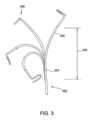
シャフト202は、作動ハンドル204に連結された近位端220と、遠位端222と、を有する。いくつかの実施形態では、シャフト202の遠位端222は撓み可能であり、作動ハンドル204は、撓み可能な遠位端222の撓みを制御するように構成される。例えば、図3に示されるように、シャフト202の遠位端222は、例示的な実施形態において、2つの反対方向に(例えば、図3に示されるように左又は右に)撓み可能である。図示のカテーテル200は、双方向カテーテルである。他の実施形態では、カテーテルは、一方向カテーテルであってもよい(すなわち、先端は、単一方向にのみ撓み可能である)。
シャフト202を構成するために様々な材料を使用することができるが、典型的には、ポリウレタン、ナイロン、又は任意の適切な非導電性材料から構成される。シャフト202は、カテーテル200の血液接触セグメントの少なくとも一部として機能し、当技術分野で周知の方法及び手段によって患者に血管挿入される。 Although various materials can be used to construct
シャフト202は、近位端220から遠位端222まで延びる細長いボディ224を含み、近位部分226及び撓み可能な遠位部分228を含む。さらに、細長いボディ224は、近位端220から遠位端222まで延びる少なくとも1つのルーメン230(図6及び7に示される)を画定する。ループ作動ワイヤ232(図6及び図7に示される)は、ルーメン230を通って延び、例えば、シャフト202の遠位端222で連結された電極ループアセンブリ248の直径を選択的に調節するように作動可能である。
さらに図4及び図5を参照すると、シャフト202の遠位端222は、電極ループアセンブリ248を含む。電極ループアセンブリ248は複数のカテーテル電極252を含み、これらは、例えば、これに限定されるものではないが、心臓マッピング及び/又はアブレーションを含む、様々な診断及び治療目的のために使用され得る。例えば、1つ又は複数のカテーテル電極252は、位置(location)又は位置(position)感知機能を実行し得る。より詳細には、1つ又は複数のカテーテル電極252は、電極ループアセンブリ248の位置(位置及び向き)に関する情報を提供する位置決めセンサであるように構成され得る。 Still referring to FIGS. 4 and 5, the
電極ループアセンブリ248の直径は、いくつかの実施形態において変更可能であってもよい。例えば、電極ループアセンブリ248は、拡張(「開」とも称する)直径(図5に示される)と収縮(「閉」とも称する)直径(図示せず)との間で移行可能な直径250(図5に示される)を有する。例示的な実施形態では、拡張直径は約27ミリメートル(mm)であり、収縮直径は約15mmである。他の実施形態では、直径250は、任意の適切な開直径と閉直径との間で変更可能であってもよい。あるいは、本開示の他の実施形態では、電極ループアセンブリ248の直径は固定されてもよい。 The diameter of
再び図2を参照すると、直径が変更可能な少なくともいくつかの実施形態では、カテーテル200は、操作者が電極ループアセンブリ248の直径を調節することを可能にする第1のアクチュエータ256、即ち、電極ループアセンブリ248の直径を増加又は減少させるためのアセンブリ又は機構を含む。さらに、シャフト202が撓み可能な遠位部分228を含む少なくともいくつかの実施形態では、カテーテル200は、操作者がシャフト202の遠位部分228を選択的に撓ませることを可能にする第2のアクチュエータ258を含む。例えば、遠位端222がループ又は投げ縄形状を形成する一実施形態では、第1のアクチュエータ256の作動は、遠位端222に電極ループアセンブリ248の直径を増減させ、第2のアクチュエータ258の作動は、遠位端222を少なくとも1つの方向に撓ませる。他の実施形態では、第1のアクチュエータ256は、遠位端222を少なくとも1つの方向に撓ませ、第2のアクチュエータ258は、遠位端222を電極ループアセンブリ248の直径を増減させる。電極ループアセンブリ248のこの直径調節は、処置中の任意の時点で行われてもよく、カテーテル200の遠位端222の撓みを伴って、又は伴わずにさらに行われてもよく、即ち、遠位端222の任意の撓みは、本開示による電極ループアセンブリ248の任意の直径調節から独立している。この独立した調節は、例えば、その開示全体が参照により本明細書に組み込まれる、「Mapping Variable Loop Catheter Handle」と題した米国特許出願公開第2017/0291008号に記載されるような、カテーテル200内に含まれる複数のプルワイヤを使用することによって達成することができる。処置前又は処置中に電極ループアセンブリ248の直径を調節する能力を有することによって、操作者は、本明細書に記載されるように、患者の血管系をより効果的にナビゲートし、患者の結果を改善することができる。 Referring again to FIG. 2, in at least some embodiments where the diameter is variable, the
図6及び図7をさらに参照すると、第1のアクチュエータ256及び第2のアクチュエータ258は、作動ワイヤ232、233によって、シャフト202の撓み可能な遠位端222に接続されてもよい。例えば、ループ作動ワイヤ232は、第1のアクチュエータ256に連結されてもよく、シャフト作動ワイヤ233は、第2のアクチュエータ258に連結されてもよい。作動ワイヤ232、233は、例えば、これに限定されるものではないが、プルワイヤ又はテンションワイヤ(すなわち、圧縮荷重を支持するように構成されていない作動ワイヤ)、及びプル/プッシュワイヤ又はテンション/圧縮ワイヤ(圧縮荷重を支持するように構成された作動ワイヤ)を含む、当技術分野で知られている作動ワイヤタイプのうち任意のものとすることができる。プル/プッシュ作動ワイヤを含む実施形態では、一方の作動ワイヤが引っ張り状態になると、他方の作動ワイヤが圧縮荷重を受ける。作動ワイヤは、超弾性ニチノールワイヤ又は別の適切な材料から形成することができる。 With further reference to FIGS. 6 and 7,
図6及び図7に示されるように、シャフト202は、細長いボディ224によって画定され、近位端220から遠位端222まで延びる複数のルーメン230を含む。図示された実施形態では、シャフト202の遠位部分228は、図6に示されるように、4つのルーメン230を含む。シャフト202の近位部分226は、図7に示されるように、単一のルーメン230を含む。導電ワイヤ260及び作動ワイヤ232、233は、ルーメン230を通って延在する。具体的には、導電ワイヤ260は、作動ハンドル204からルーメン230を通って電極ループアセンブリ248の電極252及び磁気センサまで延びている。シャフト作動ワイヤ233は、第2のアクチュエータ258から別個のルーメン230を通って延在し、第2のアクチュエータ258の作動時にシャフト202の遠位端222を撓ませるように作動可能である。さらに、少なくとも1つの作動ワイヤ232は、第1のアクチュエータ256からルーメン230を通って延び、第1のアクチュエータ256の作動時に電極ループアセンブリ248の直径250を調節するように作動可能である。 As shown in FIGS. 6 and 7,
再び図2を参照すると、図1に示すワイヤコネクタ110などのワイヤコネクタは、作動ハンドル204の近位端208にあってもよい。作動ハンドル204はまた、遠位端210にストレインリリーフ254を含むことができる。図4に示される電極ループアセンブリ248の電極252のような電極を含む実施形態では、各電極252は、シャフト202、ストレインリリーフ254、及び作動ハンドル204を通ってワイヤコネクタに向けて延びる導電ワイヤ260(図6及び図7に示される)に接続されてもよい。ワイヤコネクタは、記録、監視又はRFアブレーション装置のような装置に接続されるように構成されている。 Referring again to FIG. 2, a wire connector, such as
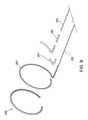
図8~図10をさらに参照すると、シャフト202は、第1のコイル234及び第2のコイル236をさらに含む。第1のコイル234は、細長いボディ224の近位部分226に沿ってループ作動ワイヤ232の周りに巻かれ、第2のコイル236は、細長いボディ224の遠位部分228に沿ってループ作動ワイヤ232の周りに巻かれる。第1のコイル234及び第2のコイル236は、シャフト202の望ましくない動きを抑制又は防止し、かつ所望の移動経路に沿ったシャフト202の動きを容易にするために、細長いボディ224の部分226、228を意図したとおり支持するように構成される。より具体的には、第1のコイル234及び第2のコイル236は、遠位部分228の制御された撓みとシャフト202の変形又は撓みに対する抵抗との間のバランスをとるために、シャフト202内に構築及び配置される。例えば、第2のコイル236は、細長いボディ224の遠位部分228を支持し、遠位部分228の選択的な撓みを可能にするために、第1のコイル234よりも可撓性のある構造を有する。第1のコイル234は、細長いボディ224の近位部分226に対する支持を提供し、ループ作動ワイヤ232が作動されるときに、シャフトのノッディング(nodding)を抑制又は防止するために、第2のコイル236よりも堅牢な、又はより剛性のある構造を有する。 With further reference to FIGS. 8-10, the
第1のコイル234及び第2のコイル236の変動する可撓性は、シャフト202が本明細書に記載されるように機能することを可能にする任意の適切なプロセス及び技術を使用して、コイルに付与されてもよい。いくつかの実施態様において、例えば、第1のコイル234及び第2のコイル236は、異なる剛性特性を有する別々の螺旋巻きワイヤで構成される。より具体的には、第1のコイル234は、第1のワイヤから構成されてもよく、第2のコイル236は、第1のワイヤの特性とは異なる少なくとも1つの特性を有する第2のワイヤから構成されてもよい。少なくとも1つの特性は、例えば、これに限定されるものではないが、ワイヤの断面積、ワイヤの固有(すなわち、材料依存)の剛性、ワイヤの引張強度、及びそれらの組み合わせを含むことができる。例えば、第1のワイヤは、第1のワイヤが第2のワイヤよりも高い剛性を有するように、第2のワイヤの断面積よりも大きい断面積を有することができる。追加的に又は代替的に、第1のワイヤは、第2のワイヤの固有剛性よりも高い固有剛性を有することができる。さらに、第1のワイヤは、第2のワイヤの引張強度よりも高い引張強度を有することができる。 The varying flexibility of
また、適切な製造プロセスを使用して、第1のコイル234及び第2のコイル236の変動する可撓性がコイルに付与されてもよい。いくつかの実施形態では、例えば、第1のコイル234及び第2のコイル236は、コイルの初期張力を変化させることによって異なる可撓性を有するように構成される。「初期張力」という用語は、コイル巻回プロセスの結果としてコイルに付与される初期又は固有の剛性を指す。例えば、コイルが巻かれるときに速度及び/又はコイルに加えられる力を制御することによって、コイルに所望の初期張力が付与されてもよい。「きつく」巻かれたコイルは、「緩く」巻かれたコイルよりも大きい初期張力を有する。いくつかの実施形態では、第1のコイル234は、第2のコイル236の初期張力よりも大きい初期張力を有するように巻かれる。 The variable flexibility of the
第1のコイル234及び第2のコイル236は、シャフト202が本明細書に記載されるように機能することを可能にする任意の適切なコイルから構成されてもよい。いくつかの実施形態では、例えば、第1のコイル234及び/又は第2のコイル236は、これに限定されるものではないが、金属ワイヤ(例えば、ステンレス鋼、ニッケルチタン合金、及び/又は他の金属)を含むワイヤ、ならびに熱硬化性材料及び熱可塑性エラストマー(例えば、ポリエチレン、ポリウレタン、及びアクリロニトリルブタジエンスチレン)を含むポリマーベースの材料から構成される。ワイヤは、第1及び第2のコイル234及び236が、本明細書に記載されるように機能することを可能にする任意の適切な断面形状を有してもよく、例えば、これに限定されるものではないが、円形ワイヤ、正方形ワイヤ、及び長方形ワイヤを含む。いくつかの実施態様において、第1のコイル234は、第2のコイル236を構成するために使用される第2のワイヤのサイズよりも大きい少なくとも1つのサイズを有する第1のワイヤから構成される。特定の一実施形態では、例えば、第1のワイヤは、約0.005インチの厚さ及び約0.008インチの幅を有し、第2のワイヤは、約0.003インチの厚さ及び約0.007インチの幅を有する。
上述のように、第1のコイル234は、作動ワイヤ232のような、シャフト202を通って延びるコンポーネントに力が加えられたときに、シャフト202の近位部分226の変形又は変位に抵抗するように構成される。第1のコイル234の性能を維持又は向上させるために、第1のコイル234の隣接するコイル間の間隔を制御又は最小化して、第1のコイル234の隣接するコイル間の互いに対する移動を低減してもよい。例えば、いくつかの実施形態では、第1のコイル234は、第1のコイル234の隣接するコイル間又はラップ間の累積間隔が約0.020インチ未満又は約0.002インチ未満であるように巻かれる。 As mentioned above,
図示の実施形態では、第1のコイル234は、第2のコイル236の長さ246よりも大きい長さ244を有する。いくつかの実施形態では、第1のコイル234の長さ244は、少なくとも約20インチ、又は、少なくとも約40インチであり、第2のコイル236の長さ246は、約2.5インチから約5.0 インチまでの範囲である。第1のコイル234は第2のコイル236よりも長く、シャフト202の大部分、即ち50%よりも大きい部分に沿って延在するため、第1のコイル234及びそれに付随するより高い剛性は、第2のコイル236と比較して、シャフト202の実質的に全体にわたるシャフトのノッディングを防止する上でより大きな役割を果たす。 In the illustrated embodiment, the
いくつかの実施形態では、第3のコイル251は、ループ作動ワイヤ232と電極ループアセンブリ248の形状ワイヤ253(図9に示される)との間のエルボ又は接続部に配置され、ループ作動ワイヤ232及び電極ループアセンブリ248に対する追加の支持を提供する。第3のコイル251が屈曲してエルボを通って延在できるように、第3のコイル251は、第1のコイル234及び第2のコイル236よりも小さく、かつ柔軟性が高いように構成されていてもよい。 In some embodiments, the
いくつかの実施形態では、支持部237は、少なくとも近位部分226の長さに沿って、第2のコイル236の少なくとも一部分上に提供される。例えば、支持部237は、図示の実施形態では、第2のコイル236の遠位部分に沿って延びる。支持部237は、電極ループアセンブリ248への接続部において、第2のコイル236及び細長いボディ224に追加の支持を提供するように構成される。いくつかの実施形態では、支持部237は、熱可塑性エラストマー材料を含む。 In some embodiments,
また、シャフト202は、接続点240で第1のコイル234と第2のコイル236とを接続し、接続点240を囲む可撓性カプラ238を含む。
可撓性カプラ238は可撓性があり、第1のコイル234及び第2のコイル236の異なる可撓性に適応する。さらに、可撓性カプラ238は、第1のコイル234及び第2のコイル236の両方に取り付けられ、第1のコイル234及び/又は第2のコイル236の屈曲中に第1のコイル234と第2のコイル236との間の接続を維持する材料を含む。いくつかの実施形態では、可撓性カプラ238は、熱可塑性樹脂を含む。
他の実施形態では、第1のコイル234及び第2のコイル236は、シャフト202が本明細書に記載されるように機能することを可能にする任意の方法で接続されてもよい。例えば、これに限定されるものではないが、いくつかの実施形態では、第1のコイル234及び第2のコイル236は、接着剤、溶接、はんだ接合、機械的ファスナ、及び/又はそれらの組み合わせによって接合される。図示の実施形態では、第1のコイル234の端部は、第1のコイル234及び第2のコイル236が重ならないように、第2のコイル236の端部に隣接する。代替的な実施形態では、第1のコイル234及び第2のコイル236の接続された部分は、部分的に互いに重なり合う。さらなる実施形態では、第1のコイル234及び第2のコイル236は、単一のワイヤ片から、その長さに沿って異なる特性を有する単一の連続コイルとして構成される。例えば、いくつかの実施態様では、第1のコイル234は、第1の初期張力で巻かれた連続コイルの第1のセグメントを含み、第2のコイル236は、第2の初期張力で巻かれた連続コイルの第2のセグメントを含む。 In other embodiments,
再び図6及び図7を参照すると、第1のコイル234及び第2のコイル236は、ルーメン230内かつ作動ワイヤ232の周囲に配置される。図示の実施形態では、作動ワイヤ232及びルーメン230は、シャフト202の長手方向軸に対して半径方向にオフセットされている。従って、作動ワイヤ232が作動されるとき、シャフト202は、第1のコイル234及び第2のコイル236がない場合にシャフトのノッディングを引き起こし得る、中心から外れた軸力を受け得る。第1のコイル234は、例えば、第1のコイル234が比較的堅固な構造を有し、シャフト202の近位部分226を通って作動ワイヤ232に沿って延びているため、作動ワイヤ232が作動するときに、中心から外れた力に対抗して作用し、シャフトのノッディングを防止するように構成される。 Referring again to FIGS. 6 and 7,
第1のコイル234及び第2のコイル236はそれぞれ、作動ワイヤ232を受け入れるように構成された中央キャビティ290を画定する。例えば、各中央キャビティ290は、作動ワイヤ232の直径よりも大きい直径を有する。中央キャビティ290は、作動ワイヤ232が第1のコイル234及び第2のコイル236のコイルから間隔をあけるための空間を提供し、第1のコイル234及び第2のコイル236が作動ワイヤ232の作動を妨害しないように、適切にサイズ決めされる。
いくつかの実施形態では、ケーシング又はスリーブは、作動ワイヤ232、第1のコイル234、及び/又は第2のコイル236上に配置される。例えば、図示の実施形態では、ケーシング292は、第1のコイル234及び第2のコイル236の周囲に延在し、第1のコイル234と第2のコイル236とシャフト202内の他のコンポーネントとの間の干渉を防止する。ケーシング292は、エラストマー高分子材料を含んでもよい。ケーシング292は、ルーメン230内で第1のコイル234及び第2のコイル236の向きを維持するように構成される。さらに、ケーシング292は、第1のコイル234及び第2のコイル236の異なる直径に対応する。例えば、図示の実施形態では、第1のコイル234が第2のコイル236よりも幅が広いため、ケーシング292は、第1のコイル234に沿った厚さよりも第2のコイル236に沿った厚さのほうが大きい。 In some embodiments, a casing or sleeve is disposed over
図11は、カテーテル(例えば、図2に示されるカテーテル200)を組み立てる方法1100の一実施形態を示すフロー図である。方法1100は、近位端から遠位端まで延在する細長いボディ(例えば、細長いボディ224)を備えるカテーテルシャフト(例えば、シャフト202)を提供するステップ1102を含む。細長いボディは、近位部分(例えば、近位部分226)及び撓み可能な遠位部分(例えば、遠位部分228)を含む。
遠位部分は、シャフトアクチュエータアセンブリ(例えば、第1のアクチュエータ256及び第2のアクチュエータ258)の作動によって、少なくとも1つの方向に選択的に撓み可能である。細長いボディは、近位端から遠位端まで延在する少なくとも1つのルーメンを画定する。FIG. 11 is a flow diagram illustrating one embodiment of a
The distal portion is selectively deflectable in at least one direction by actuation of a shaft actuator assembly (eg,
方法1100はまた、少なくとも1つのルーメン内にループ作動ワイヤ(例えば、ループ作動ワイヤ232)を配置するステップ1104を含む。ループ作動ワイヤは、細長いボディの遠位端部で連結された電極ループアセンブリ(例えば、電極ループアセンブリ248)の直径を選択的に調節するように作動可能である。
方法1100は、第1のコイル(例えば、第1のコイル234)を、細長いボディの近位部分に沿ってループ作動ワイヤの周りに配置するステップ1106と、第2のコイル(例えば、第2のコイル236)を、細長いボディの遠位部分に沿ってループ作動ワイヤの周りに配置するステップ1108と、をさらに含む。第2のコイルは、第1のコイルよりも可撓性のある構造を有する。従って、第1のコイルは、ループ作動ワイヤの作動中に、シャフトを支持し、シャフトの変形に抵抗する。さらに、第2のコイルは、遠位部分の選択的な変位を可能にする。 The
いくつかの実施形態では、方法1100は、接続点で第1のコイル及び第2のコイルを接続するステップと、接続点を可撓性カプラ(例えば可撓性カプラ238)で囲むステップと、を含む。さらなる実施形態では、方法1100は、カテーテルハンドル(例えば、カテーテルハンドル204)をカテーテルシャフトの近位端(例えば、近位端220)に取り付けるステップと、電極ループアセンブリを細長いボディの遠位端(例えば、遠位端222)に連結するステップと、を含む。 In some embodiments, the
例示的な方法の特定のステップには番号が付されているが、そのような番号は、そのステップが列挙された順序で実行されなければならないことを示すものではない。従って、特定のステップは、その説明がそのような順序を特に要求しない限り、提示される正確な順序で実行される必要はない。ステップは、列挙された順序で、又は別の適切な順序で実行されてもよい。 Although particular steps of the example method are numbered, such numbering does not imply that the steps must be performed in the order listed. Accordingly, the particular steps need not be performed in the exact order presented unless the description specifically requires such order. The steps may be performed in the order listed or in another suitable order.
本明細書に開示された実施形態及び例は、特定の実施形態を参照して説明されてきたが、これらの実施形態及び例は、本開示の原理及び用途の単なる例示であることを理解されたい。従って、例示的な実施形態及び例に対して多数の修正を行うことができ、特許請求の範囲によって定義される本開示の精神及び範囲から逸脱することなく、他の構成を考案することができることを理解されたい。従って、本出願は、これらの実施形態及びそれらの均等物の修正及び変形を包含することが意図される。 Although the embodiments and examples disclosed herein have been described with reference to particular embodiments, it is understood that these embodiments and examples are merely illustrative of the principles and applications of the disclosure. sea bream. Accordingly, numerous modifications may be made to the illustrative embodiments and examples, and other arrangements may be devised without departing from the spirit and scope of the disclosure as defined by the claims. I want you to understand. Accordingly, this application is intended to cover any modifications and variations of these embodiments and their equivalents.
本明細書は、最良の形態を含めて本発明を開示するために、また、任意の装置又はシステムを作製及び使用すること、ならびに任意の組み込まれた方法を実行することを含めて、任意の当業者が本開示を実施することを可能にするために、例を使用する。本開示の特許性のある範囲は、特許請求の範囲によって定義され、当業者に想起される他の例を含むことができる。他の例が特許請求の範囲に記載のものと相違ない構成要素を含む場合、又は他の例が特許請求の範囲に記載のものとそれほど相違ない均等な構成要素を含む場合、このような他の例は特許請求の範囲内であるものとする。
以下の項目は、国際出願時の特許請求の範囲に記載の要素である。
(項目1)
カテーテルシャフトであって、
近位端から遠位端まで延在し、近位部分及び撓み可能な遠位部分を含む細長いボディであって、前記遠位部分は、シャフトアクチュエータアセンブリの作動によって少なくとも1つの方向に選択的に撓み可能であり、前記細長いボディは、前記近位端から前記遠位端まで延在する少なくとも1つのルーメンを画定する、前記細長いボディと、
前記少なくとも1つのルーメンを通って延在し、前記細長いボディの前記遠位端で連結された電極ループアセンブリの直径を選択的に調節するように作動可能であるループ作動ワイヤと、
前記細長いボディの前記近位部分に沿って前記ループ作動ワイヤの周りに巻かれた第1のコイルと、
前記細長いボディの前記遠位部分に沿って前記ループ作動ワイヤの周りに巻かれた第2のコイルと、
を備え、
前記第2のコイルは、前記第1のコイルよりも可撓性のある構造を有する、カテーテルシャフト。
(項目2)
前記第1のコイルは、接続点で前記第2のコイルに隣接し、
前記カテーテルシャフトは、前記接続点で前記第1のコイルを前記第2のコイルに接続し、前記接続点を取り囲む可撓性カプラをさらに備える、項目1に記載のカテーテルシャフト。
(項目3)
前記可撓性カプラは、熱可塑性樹脂を備える、項目2に記載のカテーテルシャフト。
(項目4)
前記遠位部分の長さは、前記近位部分の長さ未満である、項目1に記載のカテーテルシャフト。
(項目5)
前記第1のコイルは、前記第2のコイルの初期張力よりも大きい初期張力を有する、項目1に記載のカテーテルシャフト。
(項目6)
前記第1のコイル及び前記第2のコイルは、単一の連続ワイヤから構成される、項目1に記載のカテーテルシャフト。
(項目7)
前記第1のコイルは第1のワイヤから構成され、前記第2のコイルは第2のワイヤから構成される、項目1に記載のカテーテルシャフト。
(項目8)
前記第1のワイヤの断面積は、前記第2のワイヤの断面積よりも大きい、項目7に記載のカテーテルシャフト。
(項目9)
前記第1のワイヤは、前記第2のワイヤよりも剛性が高い、項目7に記載のカテーテルシャフト。
(項目10)
前記第1のワイヤは、前記第2のワイヤよりも高い引張強度を有する、項目7に記載のカテーテルシャフト。
(項目11)
前記第1のコイルは、約0.002インチ未満である隣接するコイル間の累積間隔を有する、項目1に記載のカテーテルシャフト。
(項目12)
前記遠位部分は、前記シャフトアクチュエータアセンブリの作動によって、第1の方向及び前記第1の方向とは反対方向の第2の方向に選択的に撓み可能である、項目1に記載のカテーテルシャフト。
(項目13)
カテーテルであって、
近位端から遠位端まで延在し、近位部分及び撓み可能な遠位部分を含む細長いボディを備えるカテーテルシャフトであって、前記細長いボディは、前記近位端から前記遠位端まで延在する少なくとも1つのルーメンを画定する、前記カテーテルシャフトと、
前記細長いボディの前記遠位端で連結された電極ループアセンブリと、
前記カテーテルシャフトに取り付けられるハンドルであって、前記細長いボディの前記撓み可能な部分を少なくとも1つの方向に選択的に撓ませるように構成されたループアクチュエータアセンブリ及びシャフトアクチュエータアセンブリを含む、前記ハンドルと、
を備え、
前記カテーテルシャフトは、さらに、
前記ループアクチュエータアセンブリに接続され、前記少なくとも1つのルーメンを通って延在するループ作動ワイヤであって、前記ループアクチュエータアセンブリの作動によって、前記電極ループアセンブリの直径を選択的に調節するように作動可能である、前記ループ作動ワイヤと、
前記細長いボディの前記近位部分に沿って前記ループ作動ワイヤの周りに巻かれた第1のコイルと、
前記細長いボディの前記遠位部分に沿って前記ループ作動ワイヤの周りに巻かれた第2のコイルと、
を備え、
前記第2のコイルは、前記第1のコイルよりも可撓性のある構造を有する、カテーテル。
(項目14)
前記第1のコイルは、接続点で前記第2のコイルに隣接し、
前記カテーテルシャフトは、前記接続点で前記第1のコイルを前記第2のコイルに接続し、前記接続点を取り囲む可撓性カプラをさらに備える、項目13に記載のカテーテル。
(項目15)
前記遠位部分の長さは、前記近位部分の長さ未満である、項目13に記載のカテーテル。
(項目16)
前記遠位部分は、前記シャフトアクチュエータアセンブリの作動によって、第1の方向及び前記第1の方向とは反対の第2の方向に選択的に撓み可能である、項目13に記載のカテーテル。
(項目17)
前記第1のコイル及び前記第2のコイルは、単一の連続ワイヤから構成される、項目13に記載のカテーテル。
(項目18)
前記第1のコイルは第1のワイヤから構成され、前記第2のコイルは第2のワイヤから構成される、項目13に記載のカテーテル。
(項目19)
カテーテルの組立方法であって、
近位端から遠位端まで延在する細長いボディを備えるカテーテルシャフトを提供するステップであって、前記細長いボディは、近位部分と、撓み可能な遠位部分と、を含み、前記遠位部分は、シャフトアクチュエータアセンブリの作動によって少なくとも1つの方向に選択的に撓み可能であり、前記細長いボディは、前記近位端から前記遠位端まで延在する少なくとも1つのルーメンを画定する、前記提供するステップと、
前記少なくとも1つのルーメン内にループ作動ワイヤを配置するステップであって、前記ループ作動ワイヤは、前記細長いボディの前記遠位端で連結された電極ループアセンブリの直径を選択的に調節するように作動可能である、前記配置するステップと、
前記細長いボディの前記近位部分に沿って前記ループ作動ワイヤの周囲に第1のコイルを配置するステップと、
前記細長いボディの前記遠位部分に沿って前記ループ作動ワイヤの周囲に第2のコイルを配置するステップと、
を備え、
前記第2のコイルは、前記第1のコイルよりも可撓性のある構造を有する、方法。
(項目20)
前記第1のコイルと前記第2のコイルとを接続点で接続するステップをさらに備え、
前記カテーテルシャフトは、前記接続点で前記第1のコイルを前記第2のコイルに接続し、前記接続点を取り囲む可撓性カプラをさらに備える、
項目19に記載の方法。This specification is intended to disclose the invention, including the best mode, and to describe any method of making and using any apparatus or system and carrying out any incorporated methods. Examples are used to enable any person skilled in the art to practice the present disclosure. The patentable scope of the disclosure is defined by the claims, and may include other examples that occur to those skilled in the art. If the other examples include elements not dissimilar from those recited in the claims, or if the other examples include equivalent elements not significantly different from those recited in the claims, such other Examples are intended to be within the scope of the claims.
The following items are elements described in the claims as filed internationally.
(Item 1)
A catheter shaft,
an elongate body extending from a proximal end to a distal end and including a proximal portion and a deflectable distal portion, the distal portion being selectively deflectable in at least one direction by actuation of a shaft actuator assembly; the elongate body is deflectable and the elongate body defines at least one lumen extending from the proximal end to the distal end;
a loop actuation wire extending through the at least one lumen and operable to selectively adjust the diameter of an electrode loop assembly connected at the distal end of the elongate body;
a first coil wound around the loop actuation wire along the proximal portion of the elongated body;
a second coil wrapped around the loop actuation wire along the distal portion of the elongate body;
Equipped with
The second coil has a more flexible structure than the first coil.
(Item 2)
the first coil is adjacent to the second coil at a connection point;
2. The catheter shaft of item 1, wherein the catheter shaft further comprises a flexible coupler connecting the first coil to the second coil at the connection point and surrounding the connection point.
(Item 3)
3. The catheter shaft of item 2, wherein the flexible coupler comprises a thermoplastic resin.
(Item 4)
The catheter shaft of item 1, wherein the length of the distal portion is less than the length of the proximal portion.
(Item 5)
The catheter shaft of item 1, wherein the first coil has an initial tension that is greater than the initial tension of the second coil.
(Item 6)
The catheter shaft of item 1, wherein the first coil and the second coil are comprised of a single continuous wire.
(Item 7)
The catheter shaft of item 1, wherein the first coil is comprised of a first wire and the second coil is comprised of a second wire.
(Item 8)
8. The catheter shaft of item 7, wherein the cross-sectional area of the first wire is larger than the cross-sectional area of the second wire.
(Item 9)
8. The catheter shaft of item 7, wherein the first wire is more rigid than the second wire.
(Item 10)
8. The catheter shaft of item 7, wherein the first wire has a higher tensile strength than the second wire.
(Item 11)
The catheter shaft of item 1, wherein the first coil has a cumulative spacing between adjacent coils that is less than about 0.002 inches.
(Item 12)
The catheter shaft of item 1, wherein the distal portion is selectively deflectable in a first direction and a second direction opposite the first direction by actuation of the shaft actuator assembly.
(Item 13)
A catheter,
A catheter shaft comprising an elongate body extending from a proximal end to a distal end and including a proximal portion and a deflectable distal portion, the elongate body extending from the proximal end to the distal end. the catheter shaft defining at least one lumen containing
an electrode loop assembly connected at the distal end of the elongate body;
a handle attached to the catheter shaft, the handle including a loop actuator assembly and a shaft actuator assembly configured to selectively deflect the deflectable portion of the elongated body in at least one direction;
Equipped with
The catheter shaft further includes:
a loop actuation wire connected to the loop actuator assembly and extending through the at least one lumen, the wire being operable to selectively adjust the diameter of the electrode loop assembly by actuation of the loop actuator assembly; the loop actuation wire,
a first coil wound around the loop actuation wire along the proximal portion of the elongated body;
a second coil wrapped around the loop actuation wire along the distal portion of the elongate body;
Equipped with
The second coil has a more flexible structure than the first coil.
(Item 14)
the first coil is adjacent to the second coil at a connection point;
14. The catheter of item 13, wherein the catheter shaft further comprises a flexible coupler connecting the first coil to the second coil at the connection point and surrounding the connection point.
(Item 15)
14. The catheter of item 13, wherein the length of the distal portion is less than the length of the proximal portion.
(Item 16)
14. The catheter of item 13, wherein the distal portion is selectively deflectable in a first direction and a second direction opposite the first direction by actuation of the shaft actuator assembly.
(Item 17)
14. The catheter of item 13, wherein the first coil and the second coil are comprised of a single continuous wire.
(Item 18)
14. The catheter of item 13, wherein the first coil is comprised of a first wire and the second coil is comprised of a second wire.
(Item 19)
A method for assembling a catheter, the method comprising:
providing a catheter shaft having an elongate body extending from a proximal end to a distal end, the elongate body including a proximal portion and a deflectable distal portion; is selectively deflectable in at least one direction by actuation of a shaft actuator assembly, and wherein the elongate body defines at least one lumen extending from the proximal end to the distal end. step and
disposing a loop actuation wire within the at least one lumen, the loop actuation wire being actuated to selectively adjust a diameter of an electrode loop assembly connected at the distal end of the elongated body; the step of arranging, which is possible;
disposing a first coil around the loop actuation wire along the proximal portion of the elongate body;
disposing a second coil around the loop actuation wire along the distal portion of the elongate body;
Equipped with
The method, wherein the second coil has a more flexible structure than the first coil.
(Item 20)
further comprising the step of connecting the first coil and the second coil at a connection point,
The catheter shaft further includes a flexible coupler connecting the first coil to the second coil at the connection point and surrounding the connection point.
The method described in item 19.
Claims (20)
Translated fromJapanese近位端から遠位端まで延在し、近位部分及び撓み可能な遠位部分を含む細長いボディであって、前記遠位部分は、シャフトアクチュエータアセンブリの作動によって少なくとも1つの方向に選択的に撓み可能であり、前記細長いボディは、前記近位端から前記遠位端まで延在する少なくとも1つのルーメンを画定する、前記細長いボディと、
前記少なくとも1つのルーメンを通って延在し、前記細長いボディの前記遠位端で連結された電極ループアセンブリの直径を選択的に調節するように作動可能であるループ作動ワイヤと、
前記細長いボディの前記近位部分のみに沿って前記ループ作動ワイヤの周りに巻かれた第1のコイルと、
前記細長いボディの前記遠位部分のみに沿って前記ループ作動ワイヤの周りに巻かれた第2のコイルと、
を備え、
前記第2のコイルは、前記第1のコイルよりも可撓性のある構造を有する、カテーテルシャフト。A catheter shaft,
an elongate body extending from a proximal end to a distal end and including a proximal portion and a deflectable distal portion, the distal portion being selectively deflectable in at least one direction by actuation of a shaft actuator assembly; the elongate body is deflectable and the elongate body defines at least one lumen extending from the proximal end to the distal end;
a loop actuation wire extending through the at least one lumen and operable to selectively adjust the diameter of an electrode loop assembly connected at the distal end of the elongate body;
a first coil wrapped around the loop actuation wireonly along the proximal portion of the elongated body;
a second coil wound around the loop actuation wireonly along the distal portion of the elongated body;
Equipped with
The second coil has a more flexible structure than the first coil.
前記カテーテルシャフトは、前記接続点で前記第1のコイルを前記第2のコイルに接続し、前記接続点を取り囲む可撓性カプラをさらに備える、請求項1に記載のカテーテルシャフト。the first coil is adjacent to the second coil at a connection point;
The catheter shaft of claim 1, wherein the catheter shaft further comprises a flexible coupler connecting the first coil to the second coil at the connection point and surrounding the connection point.
近位端から遠位端まで延在し、近位部分及び撓み可能な遠位部分を含む細長いボディを備えるカテーテルシャフトであって、前記細長いボディは、前記近位端から前記遠位端まで延在する少なくとも1つのルーメンを画定する、前記カテーテルシャフトと、
前記細長いボディの前記遠位端で連結された電極ループアセンブリと、
前記カテーテルシャフトに取り付けられるハンドルであって、前記細長いボディの前記撓み可能な遠位部分を少なくとも1つの方向に選択的に撓ませるように構成されたループアクチュエータアセンブリ及びシャフトアクチュエータアセンブリを含む、前記ハンドルと、
を備え、
前記カテーテルシャフトは、さらに、
前記ループアクチュエータアセンブリに接続され、前記少なくとも1つのルーメンを通って延在するループ作動ワイヤであって、前記ループアクチュエータアセンブリの作動によって、前記電極ループアセンブリの直径を選択的に調節するように作動可能である、前記ループ作動ワイヤと、
前記細長いボディの前記近位部分のみに沿って前記ループ作動ワイヤの周りに巻かれた第1のコイルと、
前記細長いボディの前記遠位部分のみに沿って前記ループ作動ワイヤの周りに巻かれた第2のコイルと、
を備え、
前記第2のコイルは、前記第1のコイルよりも可撓性のある構造を有する、カテーテル。A catheter,
A catheter shaft comprising an elongate body extending from a proximal end to a distal end and including a proximal portion and a deflectable distal portion, the elongate body extending from the proximal end to the distal end. the catheter shaft defining at least one lumen containing
an electrode loop assembly connected at the distal end of the elongate body;
a handle attached to the catheter shaft, the handle including a loop actuator assembly and a shaft actuator assembly configured to selectively deflect the deflectable distal portion of the elongated body in at least one direction; and,
Equipped with
The catheter shaft further includes:
a loop actuation wire connected to the loop actuator assembly and extending through the at least one lumen, the wire being operable to selectively adjust the diameter of the electrode loop assembly by actuation of the loop actuator assembly; the loop actuation wire,
a first coil wrapped around the loop actuation wireonly along the proximal portion of the elongated body;
a second coil wound around the loop actuation wireonly along the distal portion of the elongated body;
Equipped with
The second coil has a more flexible structure than the first coil.
前記カテーテルシャフトは、前記接続点で前記第1のコイルを前記第2のコイルに接続し、前記接続点を取り囲む可撓性カプラをさらに備える、請求項13に記載のカテーテル。the first coil is adjacent to the second coil at a connection point;
14. The catheter of claim 13, wherein the catheter shaft further comprises a flexible coupler connecting the first coil to the second coil at the connection point and surrounding the connection point.
近位端から遠位端まで延在する細長いボディを備えるカテーテルシャフトを提供するステップであって、前記細長いボディは、近位部分と、撓み可能な遠位部分と、を含み、前記遠位部分は、シャフトアクチュエータアセンブリの作動によって少なくとも1つの方向に選択的に撓み可能であり、前記細長いボディは、前記近位端から前記遠位端まで延在する少なくとも1つのルーメンを画定する、前記提供するステップと、
前記少なくとも1つのルーメン内にループ作動ワイヤを配置するステップであって、前記ループ作動ワイヤは、前記細長いボディの前記遠位端で連結された電極ループアセンブリの直径を選択的に調節するように作動可能である、前記配置するステップと、
前記細長いボディの前記近位部分のみに沿って前記ループ作動ワイヤの周囲に第1のコイルを配置するステップと、
前記細長いボディの前記遠位部分のみに沿って前記ループ作動ワイヤの周囲に第2のコイルを配置するステップと、
を備え、
前記第2のコイルは、前記第1のコイルよりも可撓性のある構造を有する、方法。A method for assembling a catheter, the method comprising:
providing a catheter shaft having an elongate body extending from a proximal end to a distal end, the elongate body including a proximal portion and a deflectable distal portion; is selectively deflectable in at least one direction by actuation of a shaft actuator assembly, and wherein the elongate body defines at least one lumen extending from the proximal end to the distal end. step and
disposing a loop actuation wire within the at least one lumen, the loop actuation wire being actuated to selectively adjust a diameter of an electrode loop assembly connected at the distal end of the elongate body; the step of arranging, which is possible;
placing a first coil around the loop actuation wire alongonly the proximal portion of the elongate body;
placing a second coil around the loop actuation wire alongonly the distal portion of the elongated body;
Equipped with
The method, wherein the second coil has a more flexible structure than the first coil.
前記カテーテルシャフトは、前記接続点で前記第1のコイルを前記第2のコイルに接続し、前記接続点を取り囲む可撓性カプラをさらに備える、
請求項19に記載の方法。further comprising the step of connecting the first coil and the second coil at a connection point,
The catheter shaft further includes a flexible coupler connecting the first coil to the second coil at the connection point and surrounding the connection point.
20. The method according to claim 19.
Applications Claiming Priority (3)
| Application Number | Priority Date | Filing Date | Title |
|---|---|---|---|
| US201962928436P | 2019-10-31 | 2019-10-31 | |
| US62/928,436 | 2019-10-31 | ||
| PCT/US2020/054592WO2021086560A1 (en) | 2019-10-31 | 2020-10-07 | Catheter including deflectable shaft and methods of assembling same |
Publications (2)
| Publication Number | Publication Date |
|---|---|
| JP2023500018A JP2023500018A (en) | 2023-01-04 |
| JP7349562B2true JP7349562B2 (en) | 2023-09-22 |
Family
ID=73040245
Family Applications (1)
| Application Number | Title | Priority Date | Filing Date |
|---|---|---|---|
| JP2022515593AActiveJP7349562B2 (en) | 2019-10-31 | 2020-10-07 | Catheter including a deflectable shaft and method of assembling the same |
Country Status (5)
| Country | Link |
|---|---|
| US (1) | US20210128230A1 (en) |
| EP (1) | EP3998976B1 (en) |
| JP (1) | JP7349562B2 (en) |
| CN (1) | CN114521130B (en) |
| WO (1) | WO2021086560A1 (en) |
Families Citing this family (1)
| Publication number | Priority date | Publication date | Assignee | Title |
|---|---|---|---|---|
| WO2023196810A1 (en) | 2022-04-06 | 2023-10-12 | St. Jude Medical, Cardiology Division, Inc. | Hybrid mapping and pulsed field ablation catheter |
Citations (6)
| Publication number | Priority date | Publication date | Assignee | Title |
|---|---|---|---|---|
| US20070270679A1 (en) | 2006-05-17 | 2007-11-22 | Duy Nguyen | Deflectable variable radius catheters |
| US20120123326A1 (en) | 2010-11-12 | 2012-05-17 | Christian Steven C | Catheter systems with distal end function, such as distal deflection, using remote actuation or low input force |
| JP2013202241A (en) | 2012-03-29 | 2013-10-07 | Japan Lifeline Co Ltd | Electrode catheter |
| JP2013540563A (en) | 2010-10-25 | 2013-11-07 | メドトロニック アーディアン ルクセンブルク ソシエテ ア レスポンサビリテ リミテ | Catheter apparatus having a multi-electrode array for renal neuromodulation, and related systems and methods |
| JP2015515914A (en) | 2012-05-07 | 2015-06-04 | セント・ジュード・メディカル・エイトリアル・フィブリレーション・ディヴィジョン・インコーポレーテッド | Deformable catheter shaft section and catheter incorporating it |
| JP2018161476A (en) | 2017-03-27 | 2018-10-18 | バイオセンス・ウエブスター・(イスラエル)・リミテッドBiosense Webster (Israel), Ltd. | Catheter with improved loop contraction and greater contraction displacement |
Family Cites Families (18)
| Publication number | Priority date | Publication date | Assignee | Title |
|---|---|---|---|---|
| CA1231392A (en)* | 1982-10-14 | 1988-01-12 | Edward E. Elson | Flexible tip cardiac pacing catheter |
| US5562619A (en)* | 1993-08-19 | 1996-10-08 | Boston Scientific Corporation | Deflectable catheter |
| CA2174129C (en)* | 1993-10-14 | 2004-03-09 | Sidney D. Fleischman | Electrode elements for forming lesion patterns |
| US6690963B2 (en) | 1995-01-24 | 2004-02-10 | Biosense, Inc. | System for determining the location and orientation of an invasive medical instrument |
| EP0973440B1 (en) | 1998-01-22 | 2006-08-02 | Biosense Webster, Inc. | Intrabody measurement |
| US7263397B2 (en) | 1998-06-30 | 2007-08-28 | St. Jude Medical, Atrial Fibrillation Division, Inc. | Method and apparatus for catheter navigation and location and mapping in the heart |
| US7386339B2 (en) | 1999-05-18 | 2008-06-10 | Mediguide Ltd. | Medical imaging and navigation system |
| US6233476B1 (en) | 1999-05-18 | 2001-05-15 | Mediguide Ltd. | Medical positioning system |
| US7729742B2 (en)* | 2001-12-21 | 2010-06-01 | Biosense, Inc. | Wireless position sensor |
| EP1565118B1 (en)* | 2002-10-31 | 2016-03-09 | Boston Scientific Scimed, Inc. | Electrophysiology catheter with biased tip |
| US7536256B2 (en) | 2003-07-31 | 2009-05-19 | International Business Machines Corporation | Agenda replicator system and method for travelers |
| US9554691B2 (en)* | 2004-04-21 | 2017-01-31 | Acclarent, Inc. | Endoscopic methods and devices for transnasal procedures |
| US7197354B2 (en) | 2004-06-21 | 2007-03-27 | Mediguide Ltd. | System for determining the position and orientation of a catheter |
| US9220433B2 (en)* | 2011-06-30 | 2015-12-29 | Biosense Webster (Israel), Ltd. | Catheter with variable arcuate distal section |
| US9162036B2 (en)* | 2011-12-30 | 2015-10-20 | Biosense Webster (Israel), Ltd. | Medical device control handle with multiple puller wires |
| US9050010B2 (en)* | 2012-12-31 | 2015-06-09 | Biosense Webster (Israel) Ltd. | Double loop lasso with single puller wire for bi-directional actuation |
| CN109069799B (en) | 2016-04-08 | 2021-07-16 | 圣犹达医疗用品心脏病学部门有限公司 | Adjustable ring catheter handle for mapping |
| US20180228393A1 (en)* | 2017-02-15 | 2018-08-16 | Biosense Webster (Israel) Ltd. | Electrophysiologic device construction |
- 2020
- 2020-10-07JPJP2022515593Apatent/JP7349562B2/enactiveActive
- 2020-10-07CNCN202080067138.7Apatent/CN114521130B/enactiveActive
- 2020-10-07USUS17/065,190patent/US20210128230A1/enactivePending
- 2020-10-07EPEP20800390.5Apatent/EP3998976B1/enactiveActive
- 2020-10-07WOPCT/US2020/054592patent/WO2021086560A1/ennot_activeCeased
Patent Citations (6)
| Publication number | Priority date | Publication date | Assignee | Title |
|---|---|---|---|---|
| US20070270679A1 (en) | 2006-05-17 | 2007-11-22 | Duy Nguyen | Deflectable variable radius catheters |
| JP2013540563A (en) | 2010-10-25 | 2013-11-07 | メドトロニック アーディアン ルクセンブルク ソシエテ ア レスポンサビリテ リミテ | Catheter apparatus having a multi-electrode array for renal neuromodulation, and related systems and methods |
| US20120123326A1 (en) | 2010-11-12 | 2012-05-17 | Christian Steven C | Catheter systems with distal end function, such as distal deflection, using remote actuation or low input force |
| JP2013202241A (en) | 2012-03-29 | 2013-10-07 | Japan Lifeline Co Ltd | Electrode catheter |
| JP2015515914A (en) | 2012-05-07 | 2015-06-04 | セント・ジュード・メディカル・エイトリアル・フィブリレーション・ディヴィジョン・インコーポレーテッド | Deformable catheter shaft section and catheter incorporating it |
| JP2018161476A (en) | 2017-03-27 | 2018-10-18 | バイオセンス・ウエブスター・(イスラエル)・リミテッドBiosense Webster (Israel), Ltd. | Catheter with improved loop contraction and greater contraction displacement |
Also Published As
| Publication number | Publication date |
|---|---|
| JP2023500018A (en) | 2023-01-04 |
| US20210128230A1 (en) | 2021-05-06 |
| CN114521130B (en) | 2025-02-14 |
| EP3998976B1 (en) | 2024-03-27 |
| WO2021086560A1 (en) | 2021-05-06 |
| EP3998976A1 (en) | 2022-05-25 |
| CN114521130A (en) | 2022-05-20 |
Similar Documents
| Publication | Publication Date | Title |
|---|---|---|
| US20210378736A1 (en) | Catheter electrode assemblies and methods of construction thereof | |
| US11052227B2 (en) | Deflectable catheter shaft section, catheter incorporating same, and method of manufacturing same | |
| JP7326327B2 (en) | deflectable medical probe | |
| KR102313708B1 (en) | Flexible instrument with embedded actuation conduits | |
| KR102338048B1 (en) | Flexible instrument with grooved steerable tube | |
| US9078667B2 (en) | Catheter having reduced force concentration at tissue contact site | |
| EP3972511B1 (en) | Electrode loop assembly including shaped support tube and method of assembling same | |
| US11565080B2 (en) | Catheter tip assembly for a catheter shaft | |
| JP7349562B2 (en) | Catheter including a deflectable shaft and method of assembling the same | |
| CN112384164B (en) | Integrated intravascular catheter shaft | |
| US20240081795A1 (en) | Catheter including wire management cap and methods of assembling same |
Legal Events
| Date | Code | Title | Description |
|---|---|---|---|
| A521 | Request for written amendment filed | Free format text:JAPANESE INTERMEDIATE CODE: A523 Effective date:20220523 | |
| A621 | Written request for application examination | Free format text:JAPANESE INTERMEDIATE CODE: A621 Effective date:20220523 | |
| A521 | Request for written amendment filed | Free format text:JAPANESE INTERMEDIATE CODE: A523 Effective date:20221012 | |
| A977 | Report on retrieval | Free format text:JAPANESE INTERMEDIATE CODE: A971007 Effective date:20230502 | |
| A131 | Notification of reasons for refusal | Free format text:JAPANESE INTERMEDIATE CODE: A131 Effective date:20230516 | |
| A521 | Request for written amendment filed | Free format text:JAPANESE INTERMEDIATE CODE: A523 Effective date:20230814 | |
| TRDD | Decision of grant or rejection written | ||
| A01 | Written decision to grant a patent or to grant a registration (utility model) | Free format text:JAPANESE INTERMEDIATE CODE: A01 Effective date:20230829 | |
| A61 | First payment of annual fees (during grant procedure) | Free format text:JAPANESE INTERMEDIATE CODE: A61 Effective date:20230911 | |
| R150 | Certificate of patent or registration of utility model | Ref document number:7349562 Country of ref document:JP Free format text:JAPANESE INTERMEDIATE CODE: R150 |