Movatterモバイル変換


[0]ホーム

URL:


JP7349277B2 - Automated driving system for work vehicles - Google Patents

Automated driving system for work vehicles
Download PDF

Info

Publication number
JP7349277B2
JP7349277B2JP2019128308AJP2019128308AJP7349277B2JP 7349277 B2JP7349277 B2JP 7349277B2JP 2019128308 AJP2019128308 AJP 2019128308AJP 2019128308 AJP2019128308 AJP 2019128308AJP 7349277 B2JP7349277 B2JP 7349277B2
Authority
JP
Japan
Prior art keywords
obstacle
information
tractor
unit
control unit
Prior art date
Legal status (The legal status is an assumption and is not a legal conclusion. Google has not performed a legal analysis and makes no representation as to the accuracy of the status listed.)
Active
Application number
JP2019128308A
Other languages
Japanese (ja)
Other versions
JP2021015340A (en
Inventor
卓也 岩瀬
士郎 ▲杉▼田
慎也 西別府
Current Assignee (The listed assignees may be inaccurate. Google has not performed a legal analysis and makes no representation or warranty as to the accuracy of the list.)
Yanmar Co Ltd
Original Assignee
Yanmar Co Ltd
Priority date (The priority date is an assumption and is not a legal conclusion. Google has not performed a legal analysis and makes no representation as to the accuracy of the date listed.)
Filing date
Publication date
Application filed by Yanmar Co LtdfiledCriticalYanmar Co Ltd
Priority to JP2019128308ApriorityCriticalpatent/JP7349277B2/en
Priority to US17/625,810prioritypatent/US20230221728A1/en
Priority to PCT/JP2020/026932prioritypatent/WO2021006322A1/en
Priority to KR1020217035910Aprioritypatent/KR20220031542A/en
Priority to CN202080049400.5Aprioritypatent/CN114080578A/en
Priority to EP20837622.8Aprioritypatent/EP3997973B1/en
Publication of JP2021015340ApublicationCriticalpatent/JP2021015340A/en
Application grantedgrantedCritical
Publication of JP7349277B2publicationCriticalpatent/JP7349277B2/en
Activelegal-statusCriticalCurrent
Anticipated expirationlegal-statusCritical

Links

Images

Classifications

Landscapes

Description

Translated fromJapanese

本発明は、作業車両の自動走行を可能にする作業車両用の自動走行システムに関する。 The present invention relates to an automatic driving system for a work vehicle that enables automatic driving of the work vehicle.

作業車両においては、作業車両の周囲に存在する障害物を検知して当該障害物の相対位置を取得する複数の障害物検知センサと、作業車両の周囲の画像を取得する複数のカメラと、複数のカメラによって取得される複数の画像に基づいて作業車両の周囲の俯瞰画像を取得する俯瞰画像取得部と、障害物の存在を運転者に対して警告する必要のある警告領域を設定する警告領域設定部と、俯瞰画像上において障害物の相対位置が警告領域内に位置する場合に障害物の存在を運転者に警告する警告部と、を備えて作業車両の周辺を監視するように構成された周辺監視装置が装備されたものがある(例えば特許文献1参照)。 A work vehicle includes a plurality of obstacle detection sensors that detect obstacles existing around the work vehicle and obtain the relative positions of the obstacles, a plurality of cameras that obtain images of the surroundings of the work vehicle, and a plurality of an overhead image acquisition unit that acquires an overhead image of the surroundings of the work vehicle based on multiple images acquired by the camera; and a warning area that sets a warning area where it is necessary to warn the driver of the presence of an obstacle. The vehicle is configured to include a setting section and a warning section that warns the driver of the presence of an obstacle when the relative position of the obstacle is located within the warning area on the overhead image, and is configured to monitor the surroundings of the work vehicle. Some vehicles are equipped with peripheral monitoring devices (for example, see Patent Document 1).

国際公開第2012/169361号公報International Publication No. 2012/169361

前述した特許文献1に記載の周辺監視装置においては、障害物検知センサとして物体判別精度の低いレーダ装置が採用されている。そのため、前述した警告領域にて背の高い草が生えている場合や、警告領域にて埃や粉塵などが浮遊物として舞い上がった場合などにおいては、その背の高い草や浮遊物などを障害物検知センサが障害物として誤検出することがある。このような誤検出が生じると、作業車両の走行に支障を来たす障害物が存在していないにもかかわらず、警告部が、警告領域内に障害物が存在することを運転者に警告することになる。 In the surroundings monitoring device described inPatent Document 1 mentioned above, a radar device with low object discrimination accuracy is employed as an obstacle detection sensor. Therefore, if there is tall grass growing in the warning area mentioned above, or if dust or dust is flying up as a floating object in the warning area, the tall grass or floating object should be used as an obstruction. The detection sensor may erroneously detect an obstacle. When such a false detection occurs, the warning unit may warn the driver that an obstacle exists within the warning area even though there is no obstacle that would impede the movement of the work vehicle. become.

そして、このような周辺監視装置を自動走行可能な作業車両に備えた場合には、警告領域にて背の高い草が生えている場合や、警告領域にて埃や粉塵などが浮遊物として舞い上がった場合には、周辺監視装置が、それらを障害物として誤検出することに起因して、自動走行中の作業車両が不必要な走行停止などの衝突回避動作を行うことになる。 When such a surrounding monitoring device is installed on a work vehicle capable of autonomous driving, tall grass may grow in the warning area, or dust and dust may fly up as floating objects in the warning area. In such a case, the surrounding area monitoring device may erroneously detect such obstacles as obstacles, causing the automatically traveling work vehicle to perform unnecessary collision avoidance operations such as stopping the vehicle.

この実情に鑑み、本発明の主たる課題は、障害物を精度良く検出できるようにして、作業車両が不必要な衝突回避動作を行うことなく障害物との衝突を回避させることができる作業車両用の自動走行システムを提供する点にある。 In view of this situation, the main object of the present invention is to provide a work vehicle that can detect obstacles with high accuracy and avoid collisions with obstacles without the work vehicle performing unnecessary collision avoidance operations. The point is to provide an automated driving system.

本発明の第1特徴構成は、作業車両用の自動走行システムにおいて、
障害物を検出する障害物検出ユニットが備えられた作業車両を自動走行させる自動走行制御部を有し、
前記障害物検出ユニットには、前記作業車両から所定方向の設定範囲を撮像する撮像部と、前記作業車両から前記撮像部と同じ所定方向の設定範囲を測定対象とするアクティブセンサとが含まれており、
前記障害物検出ユニットが、前記撮像部の情報から前記障害物を検出し、かつ、当該障害物との離隔距離を前記アクティブセンサの情報から取得している場合は、前記自動走行制御部が、前記アクティブセンサの情報から取得した前記障害物との離隔距離に基づいて、前記作業車両と前記障害物との衝突を回避する第1衝突回避制御を実行する点にある。
A first characteristic configuration of the present invention is an automatic driving system for a work vehicle, which includes:
It has an automatic travel control unit that automatically travels a work vehicle equipped with an obstacle detection unit that detects obstacles,
The obstacle detection unit includes an imaging section that images a set range in a predetermined direction from the work vehicle, and an active sensor that measures a set range from the work vehicle in the same predetermined direction as the imaging section. Ori,
When the obstacle detection unit detects the obstacle from the information of the imaging unit and acquires the separation distance from the obstacle from the information of the active sensor, the automatic travel control unit: The present invention is characterized in that a first collision avoidance control for avoiding a collision between the work vehicle and the obstacle is executed based on a separation distance between the work vehicle and the obstacle obtained from information of the active sensor.

本構成によれば、障害物検出ユニットは、物体判別精度の高い撮像部の情報から、作業地に存在する人物や樹木などを障害物として精度よく検出することができる。又、障害物検出ユニットは、その検出した人物や樹木などの障害物との離隔距離を測距精度の高いアクティブセンサの情報から高い精度で取得することができる。そして、自動走行制御部は、アクティブセンサの情報から取得した精度の高い人物や樹木などの障害物との離隔距離に基づいて、それらの障害物に作業車両が衝突する虞を精度よく回避することができる。 According to this configuration, the obstacle detection unit can accurately detect a person, a tree, or the like existing in the work area as an obstacle based on information from the imaging unit with high object discrimination accuracy. Further, the obstacle detection unit can obtain the distance from the detected obstacle, such as a person or tree, with high accuracy from information from an active sensor with high distance measurement accuracy. The automatic driving control unit then accurately avoids the risk of the work vehicle colliding with obstacles such as people and trees based on the highly accurate separation distance from the obstacles such as people and trees obtained from the information of the active sensor. I can do it.

その結果、障害物を精度良く検出することができ、作業車両が不必要な衝突回避動作を行うことなく障害物との衝突を回避させることができる作業車両用の自動走行システムを提供することができる。 As a result, it is possible to provide an automatic driving system for a work vehicle that can accurately detect obstacles and avoid collisions with obstacles without the work vehicle performing unnecessary collision avoidance operations. can.

本発明の第2特徴構成は、
前記障害物検出ユニットが、前記撮像部の情報から前記障害物を検出しているのに対し、当該障害物との離隔距離を前記アクティブセンサの情報から取得することができない場合は、前記自動走行制御部が、前記撮像部の情報から取得した前記障害物との離隔距離に基づいて、前記第1衝突回避制御よりも衝突回避率の高い第2衝突回避制御を実行する点にある。
The second characteristic configuration of the present invention is
If the obstacle detection unit detects the obstacle from the information of the imaging unit, but cannot obtain the separation distance from the obstacle from the information of the active sensor, the automatic driving The control unit executes a second collision avoidance control having a higher collision avoidance rate than the first collision avoidance control based on a separation distance from the obstacle acquired from information of the imaging unit.

本構成によれば、自動走行制御部は、例えばアクティブセンサのセンサ表面に汚れなどの測定阻害物が付着することや、アクティブセンサの周辺にて埃や塵埃などの測定阻害物が舞い上がることに起因して、障害物との離隔距離をアクティブセンサの情報から取得することができない場合であっても、撮像部の情報から取得する障害物との離隔距離に基づいて、作業車両が障害物に衝突する虞を回避することができる。 According to this configuration, the automatic driving control unit can detect problems caused by, for example, measurement obstructions such as dirt adhering to the sensor surface of the active sensor, or measurement obstructions such as dust and dirt flying up around the active sensor. Even if the distance to the obstacle cannot be obtained from the information of the active sensor, the work vehicle will collide with the obstacle based on the distance from the obstacle obtained from the information of the imaging unit. It is possible to avoid the risk of

又、撮像部の情報から取得する障害物との離隔距離は、アクティブセンサの情報から取得する障害物との離隔距離よりも精度が低いことから、自動走行制御部は、第1衝突回避制御よりも衝突回避率の高い第2衝突回避制御を実行することで、測距精度の低下を補いながら、作業車両が障害物に衝突する虞を好適に回避することができる。 In addition, since the separation distance to the obstacle obtained from the information of the imaging unit is less accurate than the separation distance to the obstacle obtained from the information of the active sensor, the automatic driving control unit performs more control than the first collision avoidance control. By executing the second collision avoidance control which has a high collision avoidance rate, it is possible to suitably avoid the risk of the work vehicle colliding with an obstacle while compensating for the decrease in distance measurement accuracy.

尚、衝突回避率は、例えば、作業車両が減速又は停止を開始する障害物との離隔距離を長くする、あるいは、衝突回避時の車速を低くする、などの手立てを講じることで高くすることができる。 The collision avoidance rate can be increased by, for example, increasing the distance between the work vehicle and the obstacle at which it starts decelerating or stopping, or lowering the vehicle speed when avoiding a collision. can.

本発明の第3特徴構成は、
前記障害物検出ユニットが、前記撮像部の情報から前記障害物を検出しているのに対し、前記アクティブセンサの情報からは前記障害物との離隔距離を取得することができずに、前記障害物周辺との離隔距離を取得している場合は、前記自動走行制御部が、前記アクティブセンサが取得した前記障害物周辺との離隔距離に基づいて前記第1衝突回避制御を実行する点にある。
The third characteristic configuration of the present invention is
While the obstacle detection unit detects the obstacle from the information of the imaging unit, it is not possible to obtain the separation distance from the obstacle from the information of the active sensor, and the obstacle is detected by the obstacle detection unit. If the distance to the vicinity of the object has been acquired, the automatic travel control unit executes the first collision avoidance control based on the distance to the vicinity of the obstacle acquired by the active sensor. .

本構成によれば、自動走行制御部は、例えば撮像部の情報から検出した障害物が周辺の草などに紛れていることなどに起因して、その障害物との距離をアクティブセンサが測定することができずに、その障害物の周辺に位置する草などの測定対象物との距離を測定している場合には、その障害物との離隔距離に略等しい障害物周辺の測定対象物との離隔距離に基づいて、作業車両が障害物に衝突する虞を回避することができる。これにより、作業車両が障害物に衝突する虞を比較的高い精度で回避することができる。 According to this configuration, the automatic driving control unit uses the active sensor to measure the distance to the obstacle detected from the information of the imaging unit, for example, due to the fact that the obstacle is hidden in the surrounding grass, etc. If you are measuring the distance to an object such as grass located around the obstacle, the distance between the object and the object around the obstacle is approximately equal to the distance from the obstacle. Based on the separation distance, it is possible to avoid the risk of the work vehicle colliding with an obstacle. Thereby, the risk of the work vehicle colliding with an obstacle can be avoided with relatively high accuracy.

本発明の第4特徴構成は、
前記自動走行制御部は、前記アクティブセンサに対する測定阻害物の付着率が所定条件を満たした場合に、前記作業車両の車速を超低速状態まで低下させた超低速走行状態を所定時間継続し、所定時間が経過するまでの間に前記付着率が前記所定条件を満たさなくなった場合は、前記作業車両の車速を超低速状態から元の車速に復帰させ、一方、所定時間が経過するまでの間、前記付着率が前記所定条件を満たし続けた場合は、前記作業車両の自動走行を停止させる点にある。
The fourth characteristic configuration of the present invention is
The automatic driving control unit is configured to continue an ultra-low-speed driving state in which the vehicle speed of the work vehicle is reduced to an ultra-low speed state for a predetermined period of time, when a measurement obstructive adhesion rate to the active sensor satisfies a predetermined condition. If the adhesion rate no longer satisfies the predetermined condition before the time elapses, the vehicle speed of the work vehicle is returned from the ultra-low speed state to the original vehicle speed, and on the other hand, until the predetermined time elapses, If the adhesion rate continues to satisfy the predetermined condition, automatic travel of the work vehicle is stopped.

本構成によれば、単に、アクティブセンサに対する測定阻害物の付着率が所定条件を満たした場合に作業車両の自動走行を停止させるのではなく、付着率が所定条件を満たした状態が所定時間継続される条件を付加することで、所定条件を満たしている測定阻害物が、アクティブセンサに対する汚れなどの付着物か、アクティブセンサの周辺にて舞い上がっている埃や塵埃などの浮遊物かを判定することができ、その判定結果に応じて、作業車両の走行を制御することができる。 According to this configuration, the automatic traveling of the work vehicle is not simply stopped when the adhesion rate of measurement obstructions to the active sensor satisfies a predetermined condition, but the state in which the adhesion rate satisfies the predetermined condition continues for a predetermined period of time. By adding conditions that meet the predetermined conditions, it is possible to determine whether the measurement obstruction that satisfies the predetermined conditions is something attached to the active sensor, such as dirt, or floating matter, such as dust or dirt, that is flying around the active sensor. According to the determination result, the traveling of the work vehicle can be controlled.

しかも、付着率が所定条件を満たしてから所定時間が経過するまでの間は、作業車両を超低速走行状態で走行させることから、単に低速走行状態で走行させる場合に比較して、付着率が所定条件を満たしてからの所定時間、つまり、付着物か否かの判定時間を長くすることができる。これにより、所定条件を満たしている測定阻害物が埃や塵埃などの浮遊物である場合に、作業車両が停止する不都合の発生を抑制することができる。 Moreover, since the work vehicle is run at an extremely low speed until a predetermined time has elapsed after the adhesion rate satisfies the predetermined conditions, the adhesion rate is lower than when the work vehicle is simply driven at a low speed. It is possible to lengthen the predetermined time after the predetermined condition is satisfied, that is, the time required to determine whether or not there is a deposit. Thereby, it is possible to suppress the occurrence of the inconvenience of the work vehicle stopping when the measurement obstruction that satisfies the predetermined condition is a floating object such as dust or dust.

又、作業車両を超低速走行状態で走行させることで、付着物か否かの判定中に作業車両が障害物に衝突する不都合の発生を抑制することができる。 Further, by driving the work vehicle at an extremely low speed, it is possible to suppress the occurrence of an inconvenience in which the work vehicle collides with an obstacle while determining whether or not there is an attached object.

作業車両用の自動走行システムの概略構成を示す図Diagram showing the schematic configuration of an automatic driving system for work vehicles各カメラの撮像範囲を示すトラクタの平面図Plan view of the tractor showing the imaging range of each camera各ライダーセンサ及びソナーの測定範囲などを示すトラクタの側面図Side view of the tractor showing the measurement range of each lidar sensor and sonar各ライダーセンサ及びソナーの測定範囲などを示すトラクタの平面図A plan view of the tractor showing the measurement range of each lidar sensor and sonar, etc.自動走行用の目標経路の一例を示す平面図Plan view showing an example of a target route for automatic driving作業車両用の自動走行システムの概略構成を示すブロック図Block diagram showing the schematic configuration of an automatic driving system for work vehicles作業車両用の障害物検知ユニットの概略構成を示すブロック図Block diagram showing the schematic configuration of an obstacle detection unit for a work vehicle前ライダーセンサの距離画像における障害物の検出範囲と非検出範囲とを示す図Diagram showing the detection range and non-detection range of obstacles in the distance image of the front lidar sensor後ライダーセンサの距離画像における作業装置下降状態での障害物の検出範囲と非検出範囲とを示す図A diagram showing the detection range and non-detection range of obstacles in the distance image of the rear lidar sensor when the work equipment is lowered.後ライダーセンサの距離画像における作業装置上昇状態での障害物の検出範囲と非検出範囲とを示す図A diagram showing the detection range and non-detection range of obstacles in the distance image of the rear lidar sensor when the work equipment is raised.画像処理における画像処理装置の処理手順を示すフローチャートFlowchart showing the processing procedure of the image processing device in image processing各カメラの搭載位置と車体座標原点及び距離算出基準点との位置関係などを示す平面図A plan view showing the positional relationship between the mounting position of each camera and the vehicle body coordinate origin and distance calculation reference point.検出状態判定制御における情報統合処理部の処理手順を示すフローチャートFlowchart showing the processing procedure of the information integration processing unit in detection state determination control障害物未検出状態での前カメラの画像を示す図Diagram showing the image of the front camera when no obstacles are detected障害物検出状態での前カメラの画像を示す図Diagram showing the image of the front camera in the obstacle detection state障害物検出状態での前カメラの画像を示す図Diagram showing the image of the front camera in the obstacle detection state障害物未検出状態での前ライダーセンサの距離画像を示す図Diagram showing the distance image of the front lidar sensor when no obstacles are detected障害物検出状態での前ライダーセンサの距離画像を示す図Diagram showing the distance image of the front lidar sensor when an obstacle is detected障害物検出状態での前ライダーセンサの距離画像を示す図Diagram showing the distance image of the front lidar sensor when an obstacle is detected測定阻害物による障害物未検出状態での前ライダーセンサの距離画像を示す図A diagram showing the distance image of the front lidar sensor when no obstacles are detected due to measurement obstructions.測定阻害物による障害物未検出状態での前ライダーセンサの距離画像を示す図A diagram showing the distance image of the front lidar sensor when no obstacles are detected due to measurement obstructions.第1衝突回避制御における自動走行制御部の処理手順を示すフローチャートFlowchart showing the processing procedure of the automatic travel control unit in the first collision avoidance control汚れ付着判定制御における自動走行制御部の処理手順を示すフローチャートFlowchart showing the processing procedure of the automatic driving control unit in dirt adhesion determination control

以下、本発明を実施するための形態の一例として、本発明に係る作業車両用の自動走行システムを、作業車両の一例であるトラクタに適用した実施形態を図面に基づいて説明する。
尚、本発明に係る作業車両用の自動走行システムは、トラクタ以外の、例えば乗用草刈機、乗用田植機、コンバイン、運搬車、除雪車、ホイールローダ、などの乗用作業車両、及び、無人草刈機などの無人作業車両に適用することができる。
DETAILED DESCRIPTION OF THE PREFERRED EMBODIMENTS As an example of a mode for carrying out the present invention, an embodiment in which an automatic driving system for a work vehicle according to the present invention is applied to a tractor, which is an example of a work vehicle, will be described below with reference to the drawings.
Note that the automatic driving system for work vehicles according to the present invention is applicable to ride-on work vehicles other than tractors, such as riding mowers, riding rice transplanters, combine harvesters, transport vehicles, snowplows, wheel loaders, and unmanned grass cutters. It can be applied to unmanned work vehicles such as

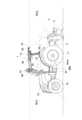
図1~4に示すように、本実施形態に例示されたトラクタ1は、その後部に3点リンク機構2を介して、作業装置の一例であるロータリ耕耘装置3が昇降可能かつローリング可能に連結されている。これにより、このトラクタ1はロータリ耕耘仕様に構成されている。トラクタ1は、作業車両用の自動走行システムを使用することにより、作業地の一例である図5に示す圃場Aなどにおいて自動走行することができる。
尚、トラクタ1の後部には、ロータリ耕耘装置3に代えて、プラウ、ディスクハロー、カルチベータ、サブソイラ、播種装置、散布装置、草刈装置、などの各種の作業装置を連結することができる。
As shown in FIGS. 1 to 4, thetractor 1 exemplified in this embodiment has arotary tiller 3, which is an example of a working device, connected to the rear of thetractor 1 via a three-point linkage mechanism 2 so that it can rise and fall and roll. has been done. Thereby, thistractor 1 is configured to rotary plowing specifications. Thetractor 1 can automatically travel in a field A shown in FIG. 5, which is an example of a work site, by using an automatic travel system for work vehicles.
Note that, instead of therotary tilling device 3, various working devices such as a plow, a disc harrow, a cultivator, a subsoiler, a seeding device, a spreading device, a mowing device, etc. can be connected to the rear of thetractor 1.

図6に示すように、自動走行システムには、トラクタ1に搭載された自動走行ユニット4と、自動走行ユニット4と無線通信可能に通信設定された無線通信機器の一例である携帯通信端末5とが含まれている。携帯通信端末5には、自動走行に関する各種の情報表示や入力操作などを可能にするマルチタッチ式の表示デバイス(例えば液晶パネル)50などが含まれている。
尚、携帯通信端末5には、タブレット型のパーソナルコンピュータやスマートフォンなどを採用することができる。又、無線通信には、Wi-Fi(登録商標)などの無線LAN(Local Area Network)やBluetooth(登録商標)などの近距離無線通信などを採用することができる。
As shown in FIG. 6, the automatic driving system includes anautomatic driving unit 4 mounted on thetractor 1, and amobile communication terminal 5, which is an example of a wireless communication device configured to communicate wirelessly with theautomatic driving unit 4. It is included. Themobile communication terminal 5 includes a multi-touch display device (for example, a liquid crystal panel) 50 that enables various information display and input operations related to automatic driving.
Note that themobile communication terminal 5 may be a tablet-type personal computer, a smartphone, or the like. Furthermore, wireless communication may include wireless LAN (Local Area Network) such as Wi-Fi (registered trademark), short-range wireless communication such as Bluetooth (registered trademark), and the like.

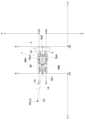
図1~3、図6に示すように、トラクタ1には、駆動可能で操舵可能な左右の前輪10、駆動可能な左右の後輪11、搭乗式の運転部12を形成するキャビン13、コモンレールシステムを有する電子制御式のディーゼルエンジン(以下、エンジンと称する)14、エンジン14などを覆うボンネット15、エンジン14からの動力を変速する変速ユニット16、左右の前輪10を操舵する全油圧式のパワーステアリングユニット17、左右の後輪11を制動するブレーキユニット18、ロータリ耕耘装置3への伝動を断続する電子油圧制御式の作業クラッチユニット19、ロータリ耕耘装置3を昇降駆動する電子油圧制御式の昇降駆動ユニット20、ロータリ耕耘装置3をロール方向に駆動する電子油圧制御式のローリングユニット21、トラクタ1における各種の設定状態や各部の動作状態などを検出する各種のセンサやスイッチなどを含む車両状態検出機器22、及び、各種の制御部を有する車載制御ユニット23、などが備えられている。
尚、エンジン14には、電子ガバナを有する電子制御式のガソリンエンジンなどを採用してもよい。又、パワーステアリングユニット17には、操舵用の電動モータを有する電動式を採用してもよい。
As shown in FIGS. 1 to 3 and FIG. 6, thetractor 1 includes drivable and steerable left and rightfront wheels 10, drivable left and rightrear wheels 11, acabin 13 forming a riding-type driving section 12, and a common rail. An electronically controlled diesel engine (hereinafter referred to as the engine) 14 that has a system, abonnet 15 that covers theengine 14, etc., atransmission unit 16 that changes the speed of the power from theengine 14, and a fully hydraulic power system that steers the left and rightfront wheels 10. Asteering unit 17, abrake unit 18 that brakes the left and rightrear wheels 11, an electro-hydraulic control typework clutch unit 19 that connects and disconnects power transmission to therotary tiller 3, and an electro-hydraulic control lifter that drives therotary tiller 3 up and down.Drive unit 20, electro-hydraulic controlled rollingunit 21 that drives therotary tiller 3 in the rolling direction, and vehicle state detection that includes various sensors and switches that detect various setting states and operating states of each part of thetractor 1. Adevice 22, an on-vehicle control unit 23 having various control sections, and the like are provided.
Note that theengine 14 may be an electronically controlled gasoline engine having an electronic governor. Further, thepower steering unit 17 may be an electric type having an electric motor for steering.

図1、図3に示すように、運転部12には、手動操舵用のステアリングホイール25と、搭乗者用の座席26と、各種の情報表示や入力操作などを可能にするマルチタッチ式の液晶モニタ27とが備えられている。図示は省略するが、運転部12には、アクセルレバーや変速レバーなどの操作レバー類、及び、アクセルペダルやクラッチペダルなどの操作ペダル類、などが備えられている。 As shown in FIGS. 1 and 3, the drivingunit 12 includes asteering wheel 25 for manual steering, aseat 26 for the passenger, and a multi-touch liquid crystal display that enables various information display and input operations. Amonitor 27 is also provided. Although not shown in the drawings, the drivingunit 12 is equipped with operating levers such as an accelerator lever and a gear shift lever, and operating pedals such as an accelerator pedal and a clutch pedal.

図示は省略するが、変速ユニット16には、エンジン14からの動力を変速する電子制御式の無段変速装置、及び、無段変速装置による変速後の動力を前進用と後進用とに切り換える電子油圧制御式の前後進切換装置、などが含まれている。無段変速装置には、静油圧式無段変速装置(HST:Hydro Static Transmission)よりも伝動効率が高い油圧機械式無段変速装置の一例であるI-HMT(Integrated Hydro-static Mechanical Transmission)が採用されている。前後進切換装置には、前進動力断続用の油圧クラッチと、後進動力断続用の油圧クラッチと、それらに対するオイルの流れを制御する電磁バルブとが含まれている。
尚、無段変速装置には、I-HMTの代わりに、油圧機械式無段変速装置の一例であるHMT(Hydraulic Mechanical Transmission)、静油圧式無段変速装置、又は、ベルト式無段変速装置、などを採用してもよい。又、変速ユニット16には、無段変速装置の代わりに、複数の変速用の油圧クラッチとそれらに対するオイルの流れを制御する複数の電磁バルブとを有する電子油圧制御式の有段変速装置が含まれていてもよい。
Although not shown, thetransmission unit 16 includes an electronically controlled continuously variable transmission that changes the speed of the power from theengine 14, and an electronically controlled continuously variable transmission that switches the power after shifting by the continuously variable transmission between forward and reverse. It includes a hydraulically controlled forward/reverse switching device. Continuously variable transmissions include I-HMT (Integrated Hydro-static Mechanical Transmission), which is an example of a hydro-mechanical continuously variable transmission that has higher transmission efficiency than Hydrostatic Transmission (HST). It has been adopted. The forward/reverse switching device includes a hydraulic clutch for intermittent forward power, a hydraulic clutch for intermittent reverse power, and an electromagnetic valve that controls the flow of oil to these clutches.
Note that, instead of the I-HMT, the continuously variable transmission may be an HMT (Hydraulic Mechanical Transmission), which is an example of a hydromechanical continuously variable transmission, a hydrostatic continuously variable transmission, or a belt-type continuously variable transmission. , etc. may be adopted. Furthermore, instead of the continuously variable transmission, thetransmission unit 16 includes an electrohydraulic-controlled stepped transmission that has a plurality of hydraulic clutches for shifting and a plurality of electromagnetic valves that control the flow of oil to the hydraulic clutches. It may be

図示は省略するが、ブレーキユニット18には、左右の後輪11を個別に制動する左右のブレーキ、運転部12に備えられた左右のブレーキペダルの踏み込み操作に連動して左右のブレーキを作動させるフットブレーキ系、運転部12に備えられたパーキングレバーの操作に連動して左右のブレーキを作動させるパーキングブレーキ系、及び、左右の前輪10の設定角度以上の操舵に連動して旋回内側のブレーキを作動させる旋回ブレーキ系、などが含まれている。 Although not shown, thebrake unit 18 includes left and right brakes that individually brake the left and rightrear wheels 11, and left and right brakes that operate in conjunction with depression of left and right brake pedals provided in thedriving section 12. A foot brake system, a parking brake system that operates the left and right brakes in conjunction with the operation of a parking lever provided in thedriving section 12, and a parking brake system that operates the brakes on the inside of the turn in conjunction with the steering of the left and rightfront wheels 10 at a set angle or more. It includes a swing brake system to operate, etc.

車両状態検出機器22は、トラクタ1の各部に備えられた各種のセンサやスイッチなどの総称である。図7に示すように、車両状態検出機器22には、トラクタ1の車速を検出する車速センサ22A、前後進切り換え用のリバーサレバーの操作位置を検出するリバーサセンサ22B、及び、前輪10の操舵角を検出する舵角センサ22C、が含まれている。又、図示は省略するが、車両状態検出機器22には、エンジン14の出力回転数を検出する回転センサ、アクセルレバーの操作位置を検出するアクセルセンサ、及び、変速レバーの操作位置を検出する変速センサ、などが含まれている。 The vehiclecondition detection device 22 is a general term for various sensors, switches, etc. provided in each part of thetractor 1. As shown in FIG. 7, the vehiclecondition detection device 22 includes avehicle speed sensor 22A that detects the vehicle speed of thetractor 1, areverser sensor 22B that detects the operating position of a reverser lever for switching forward and backward, and a steering angle of thefront wheels 10. Asteering angle sensor 22C that detects the steering angle is included. Although not shown, the vehiclecondition detection device 22 includes a rotation sensor that detects the output rotation speed of theengine 14, an accelerator sensor that detects the operating position of the accelerator lever, and a shift sensor that detects the operating position of the gear shift lever. Contains sensors, etc.

図6~7に示すように、車載制御ユニット23には、エンジン14に関する制御を行うエンジン制御部23A、トラクタ1の車速や前後進の切り換えに関する制御を行う車速制御部23B、ステアリングに関する制御を行うステアリング制御部23C、ロータリ耕耘装置3などの作業装置に関する制御を行う作業装置制御部23D、液晶モニタ27などに対する表示や報知に関する制御を行う表示制御部23E、自動走行に関する制御を行う自動走行制御部23F、及び、圃場内に区分けされた走行領域に応じて生成された自動走行用の目標経路P(図5参照)などを記憶する不揮発性の車載記憶部23G、などが含まれている。各制御部23A~23Fは、マイクロコントローラなどが集積された電子制御ユニットや各種の制御プログラムなどによって構築されている。各制御部23A~23Fは、CAN(Controller Area Network)を介して相互通信可能に接続されている。
尚、各制御部23A~23Fの相互通信には、CAN以外の通信規格や次世代通信規格である、例えば、車載EthernetやCAN-FD(CAN with FLexible Data rate)などを採用してもよい。
As shown in FIGS. 6 and 7, the on-vehicle control unit 23 includes anengine control section 23A that controls theengine 14, a vehiclespeed control section 23B that controls the vehicle speed of thetractor 1 and switching between forward and backward movement, and a vehiclespeed control section 23B that controls the steering. Asteering control section 23C, a workingdevice control section 23D that controls working devices such as therotary tiller 3, adisplay control section 23E that controls displays and notifications on theLCD monitor 27, and an automatic driving control section that controls automatic driving. 23F, and a nonvolatile in-vehicle storage unit 23G that stores a target route P for automatic driving (see FIG. 5) generated according to the driving area divided in the field. Each of thecontrol units 23A to 23F is constructed by an electronic control unit in which a microcontroller and the like are integrated, various control programs, and the like. Each of thecontrol units 23A to 23F is connected to be able to communicate with each other via a CAN (Controller Area Network).
Note that communication standards other than CAN or next-generation communication standards such as in-vehicle Ethernet or CAN-FD (CAN with Flexible Data rate) may be used for mutual communication between thecontrol units 23A to 23F.

エンジン制御部23Aは、アクセルセンサからの検出情報と回転センサからの検出情報とに基づいて、エンジン回転数をアクセルレバーの操作位置に応じた回転数に維持するエンジン回転数維持制御、などを実行する。 Theengine control unit 23A executes engine rotation speed maintenance control to maintain the engine rotation speed at a rotation speed corresponding to the operating position of the accelerator lever, etc., based on the detection information from the accelerator sensor and the detection information from the rotation sensor. do.

車速制御部23Bは、変速センサからの検出情報と車速センサ22Aからの検出情報などに基づいて、トラクタ1の車速が変速レバーの操作位置に応じた速度に変更されるように無段変速装置の作動を制御する車速制御、及び、リバーサセンサ22Bからの検出情報に基づいて前後進切換装置の伝動状態を切り換える前後進切り換え制御、などを実行する。車速制御には、変速レバーが零速位置に操作された場合に、無段変速装置を零速状態まで減速制御してトラクタ1の走行を停止させる減速停止処理が含まれている。 The vehiclespeed control unit 23B controls the continuously variable transmission so that the vehicle speed of thetractor 1 is changed to a speed corresponding to the operating position of the gear shift lever, based on the detection information from the gear shift sensor and the detection information from thevehicle speed sensor 22A. Vehicle speed control that controls the operation, forward/reverse switching control that switches the transmission state of the forward/reverse switching device based on the detection information from thereverser sensor 22B, and the like are executed. The vehicle speed control includes a deceleration and stop process in which the continuously variable transmission is decelerated to the zero speed state to stop thetractor 1 from traveling when the speed change lever is operated to the zero speed position.

作業装置制御部23Dには、PTOスイッチの操作などに基づいて作業クラッチユニット19の作動を制御する作業クラッチ制御、昇降スイッチの操作や高さ設定ダイヤルの設定値などに基づいて昇降駆動ユニット20の作動を制御する昇降制御、及び、ロール角設定ダイヤルの設定値などに基づいてローリングユニット21の作動を制御するローリング制御、などを実行する。PTOスイッチ、昇降スイッチ、高さ設定ダイヤル、及び、ロール角設定ダイヤルは、車両状態検出機器22に含まれている。 The workequipment control unit 23D includes a work clutch control that controls the operation of thework clutch unit 19 based on the operation of the PTO switch, etc., and a work clutch control that controls the operation of thework clutch unit 19 based on the operation of the lift switch and the setting value of the height setting dial. Elevation control to control the operation, rolling control to control the operation of the rollingunit 21 based on the setting value of the roll angle setting dial, etc. are executed. A PTO switch, a lift switch, a height setting dial, and a roll angle setting dial are included in the vehiclecondition detection device 22.

図6に示すように、トラクタ1には、トラクタ1の現在位置や現在方位などを測定する測位ユニット30が備えられている。測位ユニット30には、衛星測位システムの一例であるGNSS(Global Navigation Satellite System)を利用してトラクタ1の現在位置と現在方位とを測定する衛星航法装置31、及び、3軸のジャイロスコープ及び3方向の加速度センサなどを有してトラクタ1の姿勢や方位などを測定する慣性計測装置(IMU:Inertial Measurement Unit)32、などが含まれている。GNSSを利用した測位方法には、DGNSS(Differential GNSS:相対測位方式)やRTK-GNSS(Real Time Kinematic GNSS:干渉測位方式)などがある。本実施形態においては、移動体の測位に適したRTK-GNSSが採用されている。そのため、図1に示すように、圃場周辺の既知位置には、RTK-GNSSによる測位を可能にする基準局6が設置されている。 As shown in FIG. 6, thetractor 1 is equipped with apositioning unit 30 that measures the current position, current direction, etc. of thetractor 1. Thepositioning unit 30 includes asatellite navigation device 31 that measures the current position and current direction of thetractor 1 using GNSS (Global Navigation Satellite System), which is an example of a satellite positioning system, and a 3-axis gyroscope; An inertial measurement unit (IMU) 32 that has a directional acceleration sensor and the like and measures the attitude, orientation, etc. of thetractor 1 is included. Positioning methods using GNSS include DGNSS (Differential GNSS) and RTK-GNSS (Real Time Kinematic GNSS). In this embodiment, RTK-GNSS suitable for positioning of mobile objects is employed. Therefore, as shown in FIG. 1, areference station 6 that enables positioning by RTK-GNSS is installed at a known position around the field.

図1、図6に示すように、トラクタ1と基準局6とのそれぞれには、測位衛星7(図1参照)から送信された電波を受信するGNSSアンテナ33,60、及び、トラクタ1と基準局6との間における測位情報を含む各情報の無線通信を可能にする通信モジュール34,61、などが備えられている。これにより、測位ユニット30の衛星航法装置31は、トラクタ側のGNSSアンテナ33が測位衛星7からの電波を受信して得た測位情報と、基地局側のGNSSアンテナ60が測位衛星7からの電波を受信して得た測位情報とに基づいて、トラクタ1の現在位置及び現在方位を高い精度で測定することができる。又、測位ユニット30は、衛星航法装置31と慣性計測装置32とを有することにより、トラクタ1の現在位置、現在方位、姿勢角(ヨー角、ロール角、ピッチ角)を高精度に測定することができる。 As shown in FIGS. 1 and 6, thetractor 1 and thereference station 6 each includeGNSS antennas 33 and 60 that receive radio waves transmitted from the positioning satellite 7 (see FIG. 1), and thetractor 1 and thereference station 6.Communication modules 34, 61, etc. that enable wireless communication of various information including positioning information between the terminal and the terminal are provided. As a result, thesatellite navigation device 31 of thepositioning unit 30 receives the positioning information obtained by theGNSS antenna 33 on the tractor side receiving radio waves from thepositioning satellite 7, and theGNSS antenna 60 on the base station side receives the radio waves from thepositioning satellite 7. The current position and current direction of thetractor 1 can be measured with high accuracy based on the positioning information obtained by receiving the information. Furthermore, thepositioning unit 30 has asatellite navigation device 31 and aninertial measurement device 32, so that it can measure the current position, current azimuth, and attitude angle (yaw angle, roll angle, pitch angle) of thetractor 1 with high precision. I can do it.

このトラクタ1において、測位ユニット30の慣性計測装置32、GNSSアンテナ33、及び、通信モジュール34は、図1に示すアンテナユニット35に含まれている。アンテナユニット35は、キャビン13の前面側における上部の左右中央箇所に配置されている。そして、トラクタ1におけるGNSSアンテナ33の取り付け位置が、GNSSを利用してトラクタ1の現在位置などを測定するときの測位対象位置となっている。 In thistractor 1, theinertial measurement device 32,GNSS antenna 33, andcommunication module 34 of thepositioning unit 30 are included in theantenna unit 35 shown in FIG. Theantenna unit 35 is arranged at the center of the upper left and right sides of the front side of thecabin 13. The mounting position of theGNSS antenna 33 on thetractor 1 serves as a positioning target position when measuring the current position of thetractor 1 using GNSS.

図6に示すように、携帯通信端末5には、マイクロコントローラなどが集積された電子制御ユニットや各種の制御プログラムなどを有する端末制御ユニット51などが備えられている。端末制御ユニット51には、表示デバイス50などに対する表示や報知に関する制御を行う表示制御部51A、自動走行用の目標経路Pを生成する目標経路生成部51B、及び、目標経路生成部51Bが生成した目標経路Pなどを記憶する不揮発性の端末記憶部51C、などが含まれている。端末記憶部51Cには、目標経路Pの生成に使用する各種の情報として、トラクタ1の旋回半径や作業幅などの車体情報、及び、前述した測位情報から得られる圃場情報、などが記憶されている。圃場情報には、圃場Aの形状や大きさなどを特定する上において、トラクタ1を圃場Aの外周縁に沿って走行させたときにGNSSを利用して取得した圃場Aにおける複数の形状特定地点(形状特定座標)となる4つの角部地点Ap1~Ap4(図5参照)、及び、それらの角部地点Ap1~Ap4を繋いで圃場Aの形状や大きさなどを特定する矩形状の形状特定線AL(図5参照)、などが含まれている。 As shown in FIG. 6, themobile communication terminal 5 includes an electronic control unit in which a microcontroller and the like are integrated, aterminal control unit 51 having various control programs, and the like. Theterminal control unit 51 includes adisplay control section 51A that controls display and notification on thedisplay device 50, a targetroute generation section 51B that generates a target route P for automatic driving, and a targetroute generation section 51B that generates a target route P for automatic driving. It includes a non-volatileterminal storage unit 51C that stores the target route P and the like. Theterminal storage unit 51C stores various information used to generate the target route P, such as vehicle body information such as the turning radius and working width of thetractor 1, and field information obtained from the above-mentioned positioning information. There is. In order to identify the shape and size of the field A, the field information includes multiple shape specific points in the field A acquired using GNSS when thetractor 1 is driven along the outer periphery of the field A. (shape specific coordinates), four corner points Ap1 to Ap4 (see Figure 5), and rectangular shape identification that connects these corner points Ap1 to Ap4 to identify the shape and size of field A. The line AL (see FIG. 5), etc. are included.

図6に示すように、トラクタ1及び携帯通信端末5には、車載制御ユニット23と端末制御部3Bとの間における測位情報などを含む各情報の無線通信を可能にする通信モジュール28,52が備えられている。トラクタ1の通信モジュール28は、携帯通信端末5との無線通信にWi-Fiが採用される場合には、通信情報をCANとWi-Fiとの双方向に変換する変換器として機能する。端末制御部3Bは、車載制御ユニット23との無線通信にてトラクタ1の現在位置や現在方位などを含むトラクタ1に関する各種の情報を取得することができる。これにより、携帯通信端末5の表示デバイス3Aにて、目標経路Pに対するトラクタ1の現在位置や現在方位などを含む各種の情報を表示させることができる。 As shown in FIG. 6, thetractor 1 and themobile communication terminal 5 includecommunication modules 28 and 52 that enable wireless communication of various information including positioning information between the on-vehicle control unit 23 and the terminal control section 3B. It is equipped. When Wi-Fi is used for wireless communication with themobile communication terminal 5, thecommunication module 28 of thetractor 1 functions as a converter that bidirectionally converts communication information between CAN and Wi-Fi. The terminal control unit 3B can acquire various information regarding thetractor 1 including the current position and current direction of thetractor 1 through wireless communication with the on-vehicle control unit 23. Thereby, various information including the current position and current direction of thetractor 1 with respect to the target route P can be displayed on the display device 3A of themobile communication terminal 5.

目標経路生成部51Bは、車体情報に含まれたトラクタ1の旋回半径や作業幅、及び、圃場情報に含まれた圃場Aの形状や大きさ、などに基づいて目標経路Pを生成する。
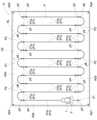
例えば、図5に示すように、矩形状の圃場Aにおいて、自動走行の開始地点p1と終了地点p2とが設定され、トラクタ1の作業走行方向が圃場Aの短辺に沿う方向に設定されている場合は、目標経路生成部51Bは、先ず、圃場Aを、前述した4つの角部地点Ap1~Ap4と矩形状の形状特定線ALとに基づいて、圃場Aの外周縁に隣接するマージン領域A1と、マージン領域A1の内側に位置する走行領域A2とに区分けする。
次に、目標経路生成部51Bは、トラクタ1の旋回半径や作業幅などに基づいて、走行領域A2に、圃場Aの長辺に沿う方向に作業幅に応じた所定間隔をあけて並列に配置される複数の並列経路P1を生成するとともに、走行領域A2における各長辺側の外縁部に配置されて複数の並列経路P1をトラクタ1の走行順に接続する複数の旋回経路P2を生成する。
そして、走行領域A2を、走行領域A2における各長辺側の外縁部に設定される一対の非作業領域A2aと、一対の非作業領域A2aの間に設定される作業領域A2bとに区分けするとともに、各並列経路P1を、一対の非作業領域A2aに含まれる非作業経路P1aと、作業領域A2bに含まれる作業経路P1bとに区分けする。
これにより、目標経路生成部51Bは、図5に示す圃場Aにおいてトラクタ1を自動走行させるのに適した目標経路Pを生成することができる。
The targetroute generation unit 51B generates a target route P based on the turning radius and working width of thetractor 1 included in the vehicle body information, the shape and size of the field A included in the field information, and the like.
For example, as shown in FIG. 5, in a rectangular farm field A, a start point p1 and an end point p2 of automatic travel are set, and the work traveling direction of thetractor 1 is set in a direction along the short side of the field A. If so, the targetpath generation unit 51B first converts the field A into a margin area adjacent to the outer periphery of the field A based on the four corner points Ap1 to Ap4 and the rectangular shape identification line AL. A1 and a running area A2 located inside the margin area A1.
Next, the targetroute generation unit 51B is arranged in parallel in the driving area A2 at a predetermined interval according to the working width in the direction along the long side of the field A based on the turning radius, working width, etc. of thetractor 1. A plurality of parallel routes P1 are generated, and a plurality of turning routes P2 are generated, which are arranged at the outer edge of each long side in the driving area A2 and connect the plurality of parallel routes P1 in the running order of thetractor 1.
Then, the driving area A2 is divided into a pair of non-working areas A2a set at the outer edge of each long side in the driving area A2, and a working area A2b set between the pair of non-working areas A2a. , each parallel route P1 is divided into a non-work route P1a included in a pair of non-work areas A2a and a work route P1b included in a work area A2b.
Thereby, the targetroute generation unit 51B can generate a target route P suitable for automatically driving thetractor 1 in the farm field A shown in FIG.

図5に示す圃場Aにおいて、マージン領域A1は、トラクタ1が走行領域A2の外周部を自動走行するときに、ロータリ耕耘装置3などが圃場Aに隣接する畦などの他物に接触することを防止するために、圃場Aの外周縁と走行領域A2との間に確保された領域である。各非作業領域A2aは、トラクタ1が圃場Aの畦際において現在の作業経路P1bから次の作業経路P1bに旋回移動するための畦際旋回領域である。 In the field A shown in FIG. 5, the margin area A1 prevents therotary tiller 3 and the like from coming into contact with other objects such as ridges adjacent to the field A when thetractor 1 automatically travels around the outer periphery of the driving area A2. In order to prevent this, this is an area secured between the outer periphery of the field A and the running area A2. Each non-working area A2a is a ridge turning area for thetractor 1 to turn from the current working route P1b to the next working route P1b at the ridge of the farm field A.

図5に示す目標経路Pにおいて、各非作業経路P1aと各旋回経路P2は、トラクタ1が耕耘作業を行わずに自動走行する経路であり、前述した各作業経路P1bは、トラクタ1が耕耘作業を行いながら自動走行する経路である。各作業経路P1bの始端地点p3は、トラクタ1が耕耘作業を開始する作業開始地点であり、各作業経路P1bの終端地点p4は、トラクタ1が耕耘作業を停止する作業停止地点である。各非作業経路P1aは、トラクタ1が旋回経路P2にて旋回走行する前の作業停止地点p4と、トラクタ1が旋回経路P2にて旋回走行した後の作業開始地点p3とを、トラクタ1の作業走行方向で揃えるための位置合せ経路である。各並列経路P1と各旋回経路P2との各接続地点p5,p6のうち、各並列経路P1における終端側の接続地点p5はトラクタ1の旋回開始地点であり、各並列経路P1における始端側の接続地点p6はトラクタ1の旋回終了地点である。 In the target route P shown in FIG. 5, each non-working route P1a and each turning route P2 are routes on which thetractor 1 automatically travels without performing tilling work, and each of the aforementioned working routes P1b is a route on which thetractor 1 travels automatically without performing tilling work. This is a route in which the vehicle travels automatically while doing the following. The starting point p3 of each work route P1b is a work start point where thetractor 1 starts plowing work, and the end point p4 of each work route P1b is a work stop point where thetractor 1 stops the plowing work. Each non-work route P1a connects a work stop point p4 before thetractor 1 turns on the turning path P2 and a work start point p3 after thetractor 1 turns on the turning path P2, and This is an alignment path for alignment in the running direction. Among the connection points p5 and p6 between each parallel path P1 and each turning path P2, the connection point p5 on the terminal side in each parallel path P1 is the turning start point of thetractor 1, and the connection point on the starting end side in each parallel path P1 Point p6 is the turning end point of thetractor 1.

尚、図5に示す目標経路Pはあくまでも一例であり、目標経路生成部51Bは、トラクタ1の機種や作業の種類などに応じて異なる車体情報、及び、圃場Aに応じて異なる圃場Aの形状や大きさなどの圃場情報、などに基づいて、それらに適した種々の目標経路Pを生成することができる。 Note that the target route P shown in FIG. 5 is just an example, and the targetroute generation unit 51B generates different vehicle body information depending on the model of thetractor 1, the type of work, etc., and a different shape of the farm field A depending on the field A. Various target routes P suitable for them can be generated based on field information such as field size and size.

目標経路Pは、車体情報や圃場情報などに関連付けされた状態で端末記憶部51Cに記憶されており、携帯通信端末5の表示デバイス50にて表示することができる。目標経路Pには、各並列経路P1におけるトラクタ1の目標車速、各旋回経路P2bにおけるトラクタ1の目標車速、各並列経路P1における前輪操舵角、及び、各旋回経路P2bにおける前輪操舵角、などが含まれている。 The target route P is stored in theterminal storage unit 51C in a state in which it is associated with vehicle body information, field information, etc., and can be displayed on thedisplay device 50 of themobile communication terminal 5. The target route P includes the target vehicle speed of thetractor 1 on each parallel route P1, the target vehicle speed of thetractor 1 on each turning route P2b, the front wheel steering angle on each parallel route P1, the front wheel steering angle on each turning route P2b, etc. include.

端末制御ユニット51は、車載制御ユニット23からの送信要求指令に応じて、端末記憶部51Cに記憶されている圃場情報や目標経路Pなどを車載制御ユニット23に送信する。車載制御ユニット23は、受信した圃場情報や目標経路Pなどを車載記憶部23Gに記憶する。目標経路Pの送信に関しては、例えば、端末制御ユニット51が、トラクタ1が自動走行を開始する前の段階において、目標経路Pの全てを端末記憶部51Cから車載制御ユニット23に一挙に送信するようにしてもよい。又、端末制御ユニット51が、目標経路Pを所定距離ごとの複数の分割経路情報に分割して、トラクタ1が自動走行を開始する前の段階からトラクタ1の走行距離が所定距離に達するごとに、トラクタ1の走行順位に応じた所定数の分割経路情報を端末記憶部51Cから車載制御ユニット23に逐次送信するようにしてもよい。 Theterminal control unit 51 transmits the field information, target route P, etc. stored in theterminal storage section 51C to the on-board control unit 23 in response to a transmission request command from the on-board control unit 23. The on-vehicle control unit 23 stores the received field information, target route P, etc. in the on-vehicle storage section 23G. Regarding the transmission of the target route P, for example, theterminal control unit 51 transmits the entire target route P from theterminal storage section 51C to the on-vehicle control unit 23 at once at a stage before thetractor 1 starts automatic travel. You can also do this. Further, theterminal control unit 51 divides the target route P into a plurality of divided route information for each predetermined distance, and each time the travel distance of thetractor 1 reaches a predetermined distance from a stage before thetractor 1 starts automatic travel. , a predetermined number of divided route information according to the running order of thetractor 1 may be sequentially transmitted from theterminal storage section 51C to the on-vehicle control unit 23.

車載制御ユニット23において、自動走行制御部23Fには、車両状態検出機器22に含まれた各種のセンサやスイッチなどからの検出情報が、車速制御部23Bやステアリング制御部23Cなどを介して入力されている。これにより、自動走行制御部23Fは、トラクタ1における各種の設定状態や各部の動作状態などを監視することができる。 In the on-vehicle control unit 23, detection information from various sensors, switches, etc. included in the vehiclecondition detection device 22 is input to the automaticdriving control section 23F via the vehiclespeed control section 23B, thesteering control section 23C, etc. ing. Thereby, the automatictravel control unit 23F can monitor various setting states and operating states of each part in thetractor 1.

自動走行制御部23Fは、搭乗者や管理者などのユーザにより、各種の自動走行開始条件を満たすための手動操作が行われてトラクタ1の走行モードが自動走行モードに切り換えられた状態において、携帯通信端末5の表示デバイス50が操作されて自動走行の開始が指令された場合に、測位ユニット30にてトラクタ1の現在位置や現在方位などを取得しながら目標経路Pに従ってトラクタ1を自動走行させる自動走行制御を開始する。 The automatictravel control unit 23F is configured to operate the mobiledrive control unit 23F in a state where the travel mode of thetractor 1 is switched to the automatic travel mode by manual operation to satisfy various automatic travel start conditions by a user such as a passenger or administrator. When thedisplay device 50 of thecommunication terminal 5 is operated to instruct the start of automatic travel, thetractor 1 is caused to travel automatically according to the target route P while thepositioning unit 30 acquires the current position, current direction, etc. of thetractor 1. Start automatic driving control.

自動走行制御部23Fは、自動走行制御の実行中に、例えば、ユーザにより携帯通信端末5の表示デバイス50が操作されて自動走行の終了が指令された場合や、運転部12に搭乗しているユーザによってステアリングホイール25やアクセルペダルなどの手動操作具が操作された場合は、自動走行制御を終了するとともに走行モードを自動走行モードから手動走行モードに切り換える。このように自動走行制御が終了された後に自動走行制御を再開させる場合は、先ず、ユーザが運転部12に乗り込んで、トラクタ1の走行モードを自動走行モードから手動走行モードに切り換える。次に、各種の自動走行開始条件を満たすための手動操作を行ってから、トラクタ1の走行モードを手動走行モードから自動走行モードに切り換える。そして、この状態において、携帯通信端末5の表示デバイス50を操作して自動走行の開始を指令することで、自動走行制御を再開させることができる。 The automaticdriving control unit 23F is activated when, for example, a user operates thedisplay device 50 of themobile communication terminal 5 to instruct the end of automatic driving while the automatic driving control is being executed, or when the user is on board the drivingunit 12. When the user operates a manual operating tool such as thesteering wheel 25 or an accelerator pedal, the automatic driving control is ended and the driving mode is switched from the automatic driving mode to the manual driving mode. When restarting the automatic travel control after the automatic travel control has been terminated in this manner, the user first gets into the drivingsection 12 and switches the travel mode of thetractor 1 from the automatic travel mode to the manual travel mode. Next, after performing manual operations to satisfy various automatic travel start conditions, the travel mode of thetractor 1 is switched from the manual travel mode to the automatic travel mode. Then, in this state, the automatic driving control can be restarted by operating thedisplay device 50 of themobile communication terminal 5 and instructing the start of automatic driving.

自動走行制御部23Fによる自動走行制御には、エンジン14に関する自動走行用の制御指令をエンジン制御部23Aに送信するエンジン用自動制御処理、トラクタ1の車速や前後進の切り換えに関する自動走行用の制御指令を車速制御部23Bに送信する車速用自動制御処理、ステアリングに関する自動走行用の制御指令をステアリング制御部23Cに送信するステアリング用自動制御処理、及び、ロータリ耕耘装置3などの作業装置に関する自動走行用の制御指令を作業装置制御部23Dに送信する作業用自動制御処理、などが含まれている。 The automatic travel control by the automatictravel control unit 23F includes an automatic engine control process that transmits a control command for automatic travel regarding theengine 14 to theengine control unit 23A, and automatic travel control regarding the vehicle speed of thetractor 1 and switching between forward and backward movement. Automated control processing for vehicle speed that sends commands to the vehiclespeed control unit 23B, automatic control processing for steering that sends control commands for automatic driving related to steering to thesteering control unit 23C, and automatic driving related to working devices such as therotary tiller 3. This includes automatic control processing for work, which transmits control commands for work to the workequipment control unit 23D, and the like.

自動走行制御部23Fは、エンジン用自動制御処理においては、目標経路Pに含まれた設定回転数などに基づいてエンジン回転数の変更を指示するエンジン回転数変更指令、などをエンジン制御部23Aに送信する。エンジン制御部23Aは、自動走行制御部23Fから送信されたエンジン14に関する各種の制御指令に応じてエンジン回転数を自動で変更するエンジン回転数変更制御、などを実行する。 In the engine automatic control process, the automatictravel control unit 23F issues an engine rotation speed change command to theengine control unit 23A to instruct the engine rotation speed to be changed based on the set rotation speed included in the target route P. Send. Theengine control unit 23A executes engine rotation speed change control that automatically changes the engine rotation speed in response to various control commands regarding theengine 14 transmitted from the automatictravel control unit 23F.

自動走行制御部23Fは、車速用自動制御処理においては、目標経路Pに含まれた目標車速に基づいて無段変速装置の変速操作を指示する変速操作指令、及び、目標経路Pに含まれたトラクタ1の進行方向などに基づいて前後進切換装置の前後進切り換え操作を指示する前後進切り換え指令、などを車速制御部23Bに送信する。車速制御部23Bは、自動走行制御部23Fから送信された無段変速装置や前後進切換装置などに関する各種の制御指令に応じて、無段変速装置の作動を自動で制御する自動車速制御、及び、前後進切換装置の作動を自動で制御する自動前後進切り換え制御、などを実行する。自動車速制御には、例えば、目標経路Pに含まれた目標車速が零速である場合に、無段変速装置を零速状態まで減速制御してトラクタ1の走行を停止させる自動減速停止処理などが含まれている。 In the vehicle speed automatic control process, the automaticdriving control unit 23F issues a speed change operation command that instructs the continuously variable transmission to perform a speed change operation based on the target vehicle speed included in the target route P, and A forward/reverse switching command for instructing a forward/reverse switching operation of the forward/reverse switching device based on the traveling direction of thetractor 1, etc. is transmitted to the vehiclespeed control unit 23B. The vehiclespeed control unit 23B performs vehicle speed control that automatically controls the operation of the continuously variable transmission in response to various control commands related to the continuously variable transmission, forward/reverse switching device, etc. transmitted from the automaticdriving control unit 23F; , automatic forward/reverse switching control that automatically controls the operation of the forward/reverse switching device, etc. The vehicle speed control includes, for example, an automatic deceleration and stop process that controls the continuously variable transmission to decelerate to a zero speed state to stop thetractor 1 from traveling when the target vehicle speed included in the target route P is zero speed. It is included.

自動走行制御部23Fは、ステアリング用自動制御処理においては、目標経路Pに含まれた前輪操舵角などに基づいて左右の前輪10の操舵を指示する操舵指令、などをステアリング制御部23Cに送信する。ステアリング制御部23Cは、自動走行制御部23Fから送信された操舵指令に応じて、パワーステアリングユニット17の作動を制御して左右の前輪10を操舵する自動操舵制御、及び、左右の前輪10が設定角度以上に操舵された場合に、ブレーキユニット18を作動させて旋回内側のブレーキを作動させる自動ブレーキ旋回制御、などを実行する。 In the automatic steering control process, the automatictravel control unit 23F transmits a steering command for instructing the steering of the left and rightfront wheels 10 based on the front wheel steering angle included in the target route P, etc. to thesteering control unit 23C. . Thesteering control unit 23C performs automatic steering control that controls the operation of thepower steering unit 17 to steer the left and rightfront wheels 10 in response to a steering command transmitted from the automatictravel control unit 23F, and controls the settings of the left and rightfront wheels 10. When the vehicle is steered beyond the angle, automatic brake turning control is executed in which thebrake unit 18 is activated to activate the brake on the inside of the turn.

自動走行制御部23Fは、作業用自動制御処理においては、目標経路Pに含まれた作業開始地点p3に基づいてロータリ耕耘装置3の作業状態への切り換えを指示する作業開始指令、及び、目標経路Pに含まれた作業停止地点p4に基づいてロータリ耕耘装置3の非作業状態への切り換えを指示する作業停止指令、などを作業装置制御部23Dに送信する。作業装置制御部23Dは、自動走行制御部23Fから送信されたロータリ耕耘装置3に関する各種の制御指令に応じて、作業クラッチユニット19と昇降駆動ユニット20の作動を制御して、ロータリ耕耘装置3を作業高さまで下降させて作動させる自動作業開始制御、及び、ロータリ耕耘装置3を停止させて非作業高さまで上昇させる自動作業停止制御、などを実行する。 In the work automatic control process, the automatictravel control unit 23F issues a work start command that instructs therotary tiller 3 to switch to the work state based on the work start point p3 included in the target route P, and a target route. Based on the work stop point p4 included in P, a work stop command that instructs therotary tiller 3 to switch to a non-work state, etc. is transmitted to the workdevice control unit 23D. The workdevice control unit 23D controls the operation of thework clutch unit 19 and the liftingdrive unit 20 in accordance with various control commands regarding therotary tillage device 3 transmitted from the automatictravel control unit 23F, and operates therotary tillage device 3. Automatic work start control in which therotary tiller 3 is lowered to a working height and activated, automatic work stop control in which therotary tiller 3 is stopped and raised to a non-working height, and the like are executed.

つまり、前述した自動走行ユニット4には、パワーステアリングユニット17、ブレーキユニット18、作業クラッチユニット19、昇降駆動ユニット20、ローリングユニット21、車両状態検出機器22、車載制御ユニット23、測位ユニット30、及び、通信モジュール28,34、などが含まれている。そして、これらが適正に作動することにより、トラクタ1を目標経路Pに従って精度よく自動走行させることができるとともに、ロータリ耕耘装置3による耕耘を適正に行うことができる。 In other words, theautomatic driving unit 4 described above includes apower steering unit 17, abrake unit 18, a workingclutch unit 19, anelevation drive unit 20, a rollingunit 21, a vehiclestate detection device 22, an on-vehicle control unit 23, apositioning unit 30, and ,communication modules 28, 34, and the like. By operating these properly, thetractor 1 can be automatically driven along the target route P with high accuracy, and therotary tiller 3 can properly perform tilling.

図6~7に示すように、トラクタ1には、トラクタ1の周囲を監視して、その周囲に存在する障害物を検出する障害物検出ユニット80が備えられている。障害物検出ユニット80が検出する障害物には、圃場Aにて作業する作業者などの人物や他の作業車両、及び、圃場Aに既存の電柱や樹木などが含まれている。 As shown in FIGS. 6 and 7, thetractor 1 is equipped with anobstacle detection unit 80 that monitors the surroundings of thetractor 1 and detects obstacles existing around thetractor 1. Obstacles detected by theobstacle detection unit 80 include people such as workers working in the field A, other work vehicles, utility poles and trees existing in the field A, and the like.

図1~4、図7に示すように、障害物検出ユニット80には、トラクタ1の周囲を撮像する撮像ユニット80A、トラクタ1の周囲に存在する測定対象物までの距離を測定するアクティブセンサユニット80B、及び、撮像ユニット80Aからの情報とアクティブセンサユニット80Bからの測定情報とを統合して処理する情報統合処理部80C、が含まれている。 As shown in FIGS. 1 to 4 and FIG. 7, theobstacle detection unit 80 includes animaging unit 80A that captures an image of the surroundings of thetractor 1, and an active sensor unit that measures the distance to a measurement object existing around thetractor 1. 80B, and an informationintegration processing section 80C that integrates and processes information from theimaging unit 80A and measurement information from theactive sensor unit 80B.

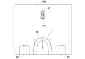
撮像ユニット80Aには、キャビン13から前方の第1撮像範囲Ri1が撮像範囲に設定された前カメラ(撮像部の一例)81、キャビン13から後方の第2撮像範囲Ri2が撮像範囲に設定された後カメラ(撮像部の一例)82、キャビン13から右方の第3撮像範囲Ri3が撮像範囲に設定された右カメラ(撮像部の一例)83、キャビン13から左方の第4撮像範囲Ri4が撮像範囲に設定された左カメラ(撮像部の一例)84、及び、各カメラ81~84からの画像を処理する画像処理装置85、が含まれている。 In theimaging unit 80A, a front camera (an example of an imaging unit) 81 has a first imaging range Ri1 in front of thecabin 13 set as an imaging range, and a second imaging range Ri2 in the rear from thecabin 13 is set as an imaging range. A rear camera (an example of an imaging unit) 82, a right camera (an example of an imaging unit) 83 whose imaging range is a third imaging range Ri3 to the right from thecabin 13, and a fourth imaging range Ri4 to the left from thecabin 13 is set as an imaging range. It includes a left camera (an example of an imaging unit) 84 set in the imaging range, and animage processing device 85 that processes images from each of thecameras 81 to 84.

図1、図3~4、図7に示すように、アクティブセンサユニット80Bには、キャビン13から前方の第1測定範囲Rm1が測定範囲に設定された前ライダーセンサ(アクティブセンサの一例)86、キャビン13から後方の第2測定範囲Rm2が測定範囲に設定された後ライダーセンサ(アクティブセンサの一例)87、及び、キャビン13から右方の第3測定範囲Rm3とキャビン13から左方の第4測定範囲Rm4とが測定範囲に設定されたソナー(アクティブセンサの一例)88、が含まれている。各ライダーセンサ86,87は、測定光の一例であるレーザ光(例えばパルス状の近赤外レーザ光)を使用して第1測定範囲Rm1又は第2測定範囲Rm2での測定を行う測定部86A,87Aと、測定部86A,87Aからの測定情報に基づいて距離画像の生成などを行うライダー制御部86B,87Bと、が含まれている。ソナー88には、右超音波センサ88Aと左超音波センサ88Bと単一のソナー制御部88Cとが含まれている。 As shown in FIGS. 1, 3 to 4, and 7, theactive sensor unit 80B includes a front lidar sensor (an example of an active sensor) 86 whose measurement range is a first measurement range Rm1 in front of thecabin 13; After the second measurement range Rm2 rearward from thecabin 13 is set as the measurement range, the lidar sensor (an example of an active sensor) 87, the third measurement range Rm3 to the right from thecabin 13, and the fourth measurement range Rm2 to the left from the cabin 13 A sonar (an example of an active sensor) 88 is included in which the measurement range Rm4 is set as the measurement range. Eachlidar sensor 86, 87 includes ameasurement unit 86A that performs measurement in a first measurement range Rm1 or a second measurement range Rm2 using a laser beam (for example, a pulsed near-infrared laser beam), which is an example of measurement light. , 87A, andlidar control units 86B and 87B that perform generation of distance images based on measurement information frommeasurement units 86A and 87A. Thesonar 88 includes a rightultrasonic sensor 88A, a leftultrasonic sensor 88B, and a singlesonar control section 88C.

情報統合処理部80C、画像処理装置85、各ライダー制御部86B,87B、及び、ソナー制御部88Cは、マイクロコントローラなどが集積された電子制御ユニットや各種の制御プログラムなどによって構築されている。情報統合処理部80C、画像処理装置85、各ライダー制御部86B,87B、及び、ソナー制御部88Cは、車載制御ユニット23にCANを介して相互通信可能に接続されている。 The informationintegration processing section 80C, theimage processing device 85, eachlidar control section 86B, 87B, and thesonar control section 88C are constructed by an electronic control unit in which a microcontroller and the like are integrated, various control programs, and the like. The informationintegration processing section 80C, theimage processing device 85, eachlidar control section 86B, 87B, and thesonar control section 88C are connected to the on-vehicle control unit 23 via CAN so that they can communicate with each other.

前カメラ81及び後カメラ82は、トラクタ1の左右中心線上に配置されている。前カメラ81は、キャビン13の前端側における上部の左右中央箇所に、トラクタ1の前方側を斜め上方側から見下ろす前下がり姿勢で配置されている。これにより、前カメラ81は、トラクタ1の左右中心線を対称軸とする車体前方側の所定範囲が第1撮像範囲Ri1に設定されている。後カメラ82は、キャビン13の後端側における上部の左右中央箇所に、トラクタ1の後方側を斜め上方側から見下ろす後下がり姿勢で配置されている。これにより、後カメラ82は、トラクタ1の左右中心線を対称軸とする車体後方側の所定範囲が第2撮像範囲Ri2に設定されている。右カメラ83は、キャビン13の右端側における上部の前後中央箇所に、トラクタ1の右方側を斜め上方側から見下ろす右下がり姿勢で配置されている。これにより、右カメラ83は、車体右方側の所定範囲が第3撮像範囲Ri3に設定されている。左カメラ84は、キャビン13の左端側における上部の前後中央箇所に、トラクタ1の左方側を斜め上方側から見下ろす左下がり姿勢で配置されている。これにより、左カメラ84は、車体左方側の所定範囲が第4撮像範囲Ri4に設定されている。 Thefront camera 81 and therear camera 82 are arranged on the left and right center line of thetractor 1. Thefront camera 81 is disposed at the left-right center of the upper part of the front end side of thecabin 13 in a forward-sloping posture looking down on the front side of thetractor 1 from diagonally above. Thereby, in thefront camera 81, a predetermined range on the front side of the vehicle body with the left-right center line of thetractor 1 as the axis of symmetry is set as the first imaging range Ri1. Therear camera 82 is disposed at the left-right center of the upper part on the rear end side of thecabin 13 in a backward-sloping position looking down on the rear side of thetractor 1 from diagonally above. Thereby, in therear camera 82, a predetermined range on the rear side of the vehicle body with the left-right center line of thetractor 1 as the axis of symmetry is set as the second imaging range Ri2. Theright camera 83 is disposed at the front-rear center of the upper part on the right end side of thecabin 13 in a downward-sloping position looking down on the right side of thetractor 1 from diagonally above. As a result, theright camera 83 has a predetermined range on the right side of the vehicle body set as the third imaging range Ri3. Theleft camera 84 is disposed at the front-rear center of the upper part on the left end side of thecabin 13 in a left-down position looking down on the left side of thetractor 1 from diagonally above. As a result, theleft camera 84 has a predetermined range on the left side of the vehicle body set as the fourth imaging range Ri4.

各ライダーセンサ86,87において、各測定部86A,87Aは、照射したレーザ光が測距点に到達して戻るまでの往復時間に基づいて測距点までの距離を測定するTOF(Time Of Flight)方式により、各測定部86A,87Aから第1測定範囲Rm1又は第2測定範囲Rm2の各測距点(測定対象物の一例)までの距離を測定する。各測定部86A,87Aは、第1測定範囲Rm1又は第2測定範囲Rm2の全体にわたって、レーザ光を高速で縦横に走査して、走査角(座標)ごとの測距点までの距離を順次測定することで、第1測定範囲Rm1又は第2測定範囲Rm2において3次元の測定を行う。各測定部86A,87Aは、第1測定範囲Rm1又は第2測定範囲Rm2の全体にわたってレーザ光を高速で縦横に走査したときに得られる各測距点からの反射光の強度(以下、反射強度と称する)を順次測定する。各測定部86A,87Aは、第1測定範囲Rm1又は第2測定範囲Rm2の各測距点までの距離や各反射強度などをリアルタイムで繰り返し測定する。各ライダー制御部86B,87Bは、各測定部86A,87Aが測定した各測距点までの距離や各測距点に対する走査角(座標)などの測定情報から、距離画像を生成するとともに障害物と推定される測距点群を抽出し、抽出した測距点群に関する測定情報を、障害物候補に関する測定情報として情報統合処理部80Cに送信する。 In eachlidar sensor 86, 87, eachmeasurement unit 86A, 87A is a TOF (Time of Flight) which measures the distance to the distance measurement point based on the round trip time for the irradiated laser beam to reach the distance measurement point and return. ) method, the distances from each measuringunit 86A, 87A to each distance measuring point (an example of a measurement target) in the first measurement range Rm1 or the second measurement range Rm2 are measured. Eachmeasurement unit 86A, 87A scans the laser beam vertically and horizontally at high speed over the entire first measurement range Rm1 or second measurement range Rm2, and sequentially measures the distance to the distance measurement point for each scanning angle (coordinate). By doing so, three-dimensional measurement is performed in the first measurement range Rm1 or the second measurement range Rm2. Eachmeasurement unit 86A, 87A measures the intensity of reflected light from each ranging point (hereinafter referred to as reflected intensity ) are measured sequentially. Each measuringsection 86A, 87A repeatedly measures the distance to each distance measurement point, each reflection intensity, etc. in the first measurement range Rm1 or the second measurement range Rm2 in real time. Eachlidar control section 86B, 87B generates a distance image from measurement information such as the distance to each distance measurement point measured by eachmeasurement section 86A, 87A and the scanning angle (coordinates) for each distance measurement point, and also generates a distance image. A group of ranging points estimated to be extracted is extracted, and measurement information regarding the extracted ranging point group is transmitted to the informationintegration processing unit 80C as measurement information regarding the obstacle candidate.

各ライダー制御部86B,87Bは、各測定部86A,87Aが測定した各測距点の距離値が無効条件に適合するか否かを判定し、無効条件に適合する距離値を無効値として情報統合処理部80Cに送信する。
具体的には、各ライダー制御部86B,87Bは、各ライダーセンサ86,87からの至近距離に存在するという各ライダーセンサ86,87におけるセンサ表面の汚れの特徴を利用して、その特徴を有する測距点の距離値を無効値とする。これにより、センサ表面の汚れに関する測距点の距離値が、情報統合処理部80Cにおいて障害物に関する情報として使用されることを防止している。
各ライダー制御部86B,87Bは、各ライダーセンサ86,87の近距離に存在しながら反射強度が非常に弱いという埃や霧などの浮遊物の特徴を利用して、その特徴を有する測距点の距離値を無効値とする。これにより、浮遊物に関する測距点の距離値が、情報統合処理部80Cにおいて障害物に関する情報として使用されることを防止している。
Eachlidar control unit 86B, 87B determines whether the distance value of each distance measurement point measured by eachmeasurement unit 86A, 87A satisfies an invalid condition, and records the distance value that conforms to the invalid condition as an invalid value. It is transmitted to theintegrated processing unit 80C.
Specifically, eachlidar control unit 86B, 87B has the characteristic by utilizing the characteristic of dirt on the sensor surface of eachlidar sensor 86, 87 that is present at a close distance from eachlidar sensor 86, 87. The distance value of the distance measurement point is set as an invalid value. This prevents the distance value of the distance measurement point regarding dirt on the sensor surface from being used as information regarding the obstacle in the informationintegration processing section 80C.
Eachlidar control unit 86B, 87B utilizes the characteristics of floating objects such as dust and fog that are present at a short distance from eachlidar sensor 86, 87 but have very low reflection intensity, and uses the characteristics of floating objects such as dust and fog to The distance value is set as an invalid value. This prevents the distance value of the ranging point regarding the floating object from being used as information regarding the obstacle in the informationintegration processing section 80C.

図1、図3~4に示すように、前ライダーセンサ86及び後ライダーセンサ87は、前カメラ81及び後カメラ82と同様にトラクタ1の左右中心線上に配置されている。前ライダーセンサ86は、キャビン13の前端側における上部の左右中央箇所に、トラクタ1の前方側を斜め上方側から見下ろす前下がり姿勢で配置されている。これにより、前ライダーセンサ86は、トラクタ1の左右中心線を対称軸とする車体前方側の所定範囲が測定部86Aによる第1測定範囲Rm1に設定されている。後ライダーセンサ87は、キャビン13の後端側における上部の左右中央箇所に、トラクタ1の後方側を斜め上方側から見下ろす後下がり姿勢で配置されている。これにより、後ライダーセンサ87は、トラクタ1の左右中心線を対称軸とする車体後方側の所定範囲が測定部87Aによる第2測定範囲Rm2に設定されている。 As shown in FIGS. 1 and 3 to 4, thefront rider sensor 86 and therear rider sensor 87 are arranged on the left-right center line of thetractor 1, similarly to thefront camera 81 and therear camera 82. Thefront rider sensor 86 is disposed at the left-right center of the upper part on the front end side of thecabin 13 in a forward-sloping posture looking down on the front side of thetractor 1 from diagonally above. Thereby, in thefront rider sensor 86, a predetermined range on the front side of the vehicle body with the left-right center line of thetractor 1 as an axis of symmetry is set as the first measurement range Rm1 by themeasurement unit 86A. Therear rider sensor 87 is disposed at the left-right center of the upper part on the rear end side of thecabin 13 in a backward-sloping posture looking down on the rear side of thetractor 1 from diagonally above. Thereby, in therear rider sensor 87, a predetermined range on the rear side of the vehicle body with the left-right center line of thetractor 1 as the axis of symmetry is set as the second measurement range Rm2 by themeasurement unit 87A.

前ライダーセンサ86及び後ライダーセンサ87は、変速ユニット16の前後進切換装置が前進伝動状態に切り換えられたトラクタ1の前進走行時には、その切り換えに連動して、前ライダーセンサ86が作動状態になり、後ライダーセンサ87が作動停止状態になる。又、変速ユニット16の前後進切換装置が後進伝動状態に切り換えられたトラクタ1の後進走行時には、その切り換えに連動して、前ライダーセンサ86が作動停止状態になり、後ライダーセンサ87が作動状態になる。 Thefront rider sensor 86 and therear rider sensor 87 are configured such that when thetractor 1 is traveling forward with the forward/reverse switching device of thetransmission unit 16 switched to the forward transmission state, thefront rider sensor 86 is activated in conjunction with the switching. , therear rider sensor 87 becomes inactive. Further, when thetractor 1 is traveling in reverse with the forward/reverse switching device of thetransmission unit 16 switched to the reverse transmission state, thefront rider sensor 86 becomes inoperative and therear rider sensor 87 becomes in the operating state in conjunction with the switching. become.

図1、図3~4、図7に示すように、ソナー88において、ソナー制御部88Cは、左右の超音波センサ88A,88Bによる超音波の送受信に基づいて、第3測定範囲Rm3又は第4測定範囲Rm4における測定対象物の存否を判定する。ソナー制御部88Cは、発信した超音波が測距点に到達して戻るまでの往復時間に基づいて測距点までの距離を測定するTOF(Time Of Flight)方式により、各超音波センサ88A,88Bから測定対象物までの距離を測定し、測定した測定対象物までの距離と測定対象物の方向とを、障害物候補に関する測定情報として情報統合処理部80Cに送信する。 As shown in FIGS. 1, 3 to 4, and 7, in thesonar 88, thesonar control unit 88C controls the third measurement range Rm3 or the fourth The presence or absence of the measurement target object in the measurement range Rm4 is determined. Thesonar control unit 88C controls eachultrasonic sensor 88A, The distance from 88B to the object to be measured is measured, and the measured distance to the object to be measured and the direction of the object to be measured are transmitted to the informationintegration processing section 80C as measurement information regarding the obstacle candidate.

図示は省略するが、右超音波センサ88Aは、右側の前輪10と右側の後輪11との間に配置された右側の乗降ステップに車体右外向き姿勢で取り付けられている。これにより、右超音波センサ88Aは、車体右外側の所定範囲が第3測定範囲Rm3に設定されている。図1~3に示すように、左超音波センサ88Bは、左側の前輪10と左側の後輪11との間に配置された左側の乗降ステップ24に車体左外向き姿勢で取り付けられている。これにより、左超音波センサ88Bは、車体左外側の所定範囲が第4測定範囲Rm4に設定されている。 Although not shown in the drawings, the rightultrasonic sensor 88A is attached to a right-hand ingress/egress step disposed between the right-hand front wheel 10 and the right-handrear wheel 11 so as to face outward to the right of the vehicle body. As a result, the rightultrasonic sensor 88A has a predetermined range on the right outer side of the vehicle body set as the third measurement range Rm3. As shown in FIGS. 1 to 3, the leftultrasonic sensor 88B is attached to the left ingress/egress step 24 disposed between theleft front wheel 10 and the leftrear wheel 11 so as to face outward to the left of the vehicle body. As a result, the leftultrasonic sensor 88B has a predetermined range on the left outer side of the vehicle body set as the fourth measurement range Rm4.

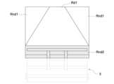
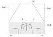
図4、図8~10に示すように、各ライダー制御部86B,87Bは、各測定部86A,87Aの測定範囲Rm1,Rm2に対して車体情報などに基づくカット処理とマスキング処理とを施すことにより、前述した障害物候補を検出対象とする第1検出範囲Rd1と第2検出範囲Rd2とを設定している。各ライダー制御部86B,87Bは、カット処理においては、車載制御ユニット23との通信によってロータリ耕耘装置3を含む車体の最大左右幅(本実施形態ではロータリ耕耘装置3の左右幅)を取得し、この車体の最大左右幅に所定の安全帯域を加えることで障害物候補の検出対象幅Wdを設定している。そして、第1測定範囲Rm1及び第2測定範囲Rm2において、検出対象幅Wdから外れる左右の範囲をカット処理による第1非検出範囲Rnd1に設定して各検出範囲Rd1,Rd2から除外する。各ライダー制御部86B,87Bは、マスキング処理においては、第1測定範囲Rm1に対してトラクタ1の前端側が入り込む範囲、及び、第2測定範囲Rm2に対してロータリ耕耘装置3の後端側が入り込む範囲に所定の安全帯域を加えた範囲をマスキング処理による第2非検出範囲Rnd2に設定して各検出範囲Rd1,Rd2から除外する。これにより、各ライダーセンサ86,87による障害物候補の検出対象範囲が第1検出範囲Rd1と第2検出範囲Rd2とに制限されている。そして、この制限により、各ライダーセンサ86,87が、検出対象幅Wdから外れていてトラクタ1と衝突する虞のない障害物候補を検出することによる検出負荷の増大や、第1測定範囲Rm1又は第2測定範囲Rm2に入り込んでいるトラクタ1の前端側やロータリ耕耘装置3などのトラクタ1の後端側を障害物候補として誤検出する虞を回避している。 As shown in FIGS. 4 and 8 to 10, eachrider control unit 86B, 87B performs a cutting process and a masking process based on vehicle body information etc. on the measurement ranges Rm1, Rm2 of eachmeasurement unit 86A, 87A. Accordingly, a first detection range Rd1 and a second detection range Rd2 are set in which the aforementioned obstacle candidates are detected. In the cutting process, eachrider control unit 86B, 87B obtains the maximum lateral width of the vehicle body including the rotary tiller 3 (in this embodiment, the lateral width of the rotary tiller 3) through communication with the on-vehicle control unit 23, The detection target width Wd of the obstacle candidate is set by adding a predetermined safety band to the maximum lateral width of the vehicle body. Then, in the first measurement range Rm1 and the second measurement range Rm2, the left and right ranges that deviate from the detection target width Wd are set as the first non-detection range Rnd1 by cutting processing and excluded from each detection range Rd1, Rd2. In the masking process, eachrider control unit 86B, 87B sets a range in which the front end side of thetractor 1 enters into the first measurement range Rm1, and a range into which the rear end side of therotary tilling device 3 enters into the second measurement range Rm2. A range obtained by adding a predetermined safety band to the above is set as a second non-detection range Rnd2 by masking processing, and is excluded from each detection range Rd1, Rd2. Thereby, the detection range of the obstacle candidate by eachlidar sensor 86, 87 is limited to the first detection range Rd1 and the second detection range Rd2. Due to this restriction, eachlidar sensor 86, 87 may increase the detection load due to detecting an obstacle candidate that is out of the detection target width Wd and has no risk of colliding with thetractor 1, or the first measurement range Rm1 or This avoids the possibility of erroneously detecting the front end of thetractor 1 or the rear end of thetractor 1, such as therotary tiller 3, entering the second measurement range Rm2 as an obstacle candidate.

尚、図8に示す第2非検出範囲Rnd2は、左右の前輪10やボンネット15が存在する車体の前部側に適した非検出範囲の一例である。図9に示す第2非検出範囲Rnd2は、車体の後部側においてロータリ耕耘装置3を作業高さまで下降させた作業状態に適した非検出範囲の一例である。図10に示す第2非検出範囲Rnd2は、車体の後部側においてロータリ耕耘装置3を退避高さまで上昇させた非作業状態に適した非検出範囲の一例である。車体後部側の第2非検出範囲Rnd2は、ロータリ耕耘装置3の昇降に連動して適正に切り換わる。 Note that the second non-detection range Rnd2 shown in FIG. 8 is an example of a non-detection range suitable for the front side of the vehicle body where the left and rightfront wheels 10 and thebonnet 15 are present. The second non-detection range Rnd2 shown in FIG. 9 is an example of a non-detection range suitable for a working state in which therotary tiller 3 is lowered to the working height on the rear side of the vehicle body. The second non-detection range Rnd2 shown in FIG. 10 is an example of a non-detection range suitable for a non-working state in which therotary tiller 3 is raised to the retracted height on the rear side of the vehicle body. The second non-detection range Rnd2 on the rear side of the vehicle body is appropriately switched in conjunction with the vertical movement of therotary tiller 3.

第1検出範囲Rd1、第2検出範囲Rd2、第1非検出範囲Rnd1、及び、第2非検出範囲Rnd2に関する情報は、前述した距離画像に含まれており、前述した距離画像とともに情報統合処理部80Cに送信されている。 Information regarding the first detection range Rd1, the second detection range Rd2, the first non-detection range Rnd1, and the second non-detection range Rnd2 is included in the above-mentioned distance image, and together with the above-mentioned distance image, the information integration processing unit It is being sent to 80C.

図4に示すように、各ライダーセンサ86,87の検出範囲Rd1,Rd2は、衝突予測時間が設定時間(例えば3秒)になる衝突判定処理に基づいて、停止制御範囲Rscと減速制御範囲Rdcと報知制御範囲Rncとに区画されている。停止制御範囲Rscは、各ライダーセンサ86,87から衝突判定処理の判定基準位置までの範囲に設定されている。減速制御範囲Rdcは、判定基準位置から減速開始位置までの範囲に設定されている。報知制御範囲Rncは、減速開始位置からライダーセンサ86,87の測定限界位置までの範囲に設定されている。各判定基準位置は、ロータリ耕耘装置3を含む車体の前端又は後端から車体前後方向に一定の離隔距離L(例えば2000mm)を置いた位置に設定されている。 As shown in FIG. 4, the detection ranges Rd1 and Rd2 of eachlidar sensor 86 and 87 are determined based on a collision determination process in which the predicted collision time becomes a set time (for example, 3 seconds), and a stop control range Rsc and a deceleration control range Rd. and a notification control range Rnc. The stop control range Rsc is set to a range from eachlidar sensor 86, 87 to a determination reference position for collision determination processing. The deceleration control range Rdc is set from the determination reference position to the deceleration start position. The notification control range Rnc is set from the deceleration start position to the measurement limit positions of thelidar sensors 86 and 87. Each determination reference position is set at a position that is a certain distance L (for example, 2000 mm) from the front end or rear end of the vehicle body including therotary tilling device 3 in the longitudinal direction of the vehicle body.

画像処理装置85は、各カメラ81~84から順次送信される画像に対して画像処理を行う。
尚、画像処理装置85には、圃場Aにて作業する作業者などの人物や他の作業車両、及び、圃場Aに既存の電柱や樹木などを障害物として認識するための学習処理が施されている。
Theimage processing device 85 performs image processing on images sequentially transmitted from each of thecameras 81 to 84.
Theimage processing device 85 is subjected to learning processing to recognize people such as workers working in the field A, other work vehicles, and electric poles and trees existing in the field A as obstacles. ing.

以下、図11に示すフローチャートに基づいて、画像処理における画像処理装置85の処理手順について説明する。 Hereinafter, the processing procedure of theimage processing device 85 in image processing will be explained based on the flowchart shown in FIG.

画像処理装置85は、各カメラ81~84から順次送信される画像に対して、先ず、全カメラ81~84からの画像を合成してトラクタ1の全周囲画像(例えばサラウンドビュー)を生成する全周囲画像生成処理を行い(ステップ#1)、生成した全周囲画像や各カメラ81~84からの画像を、トラクタ側の表示制御部23Eや携帯通信端末側の表示制御部51Aに送信する画像送信処理を行う(ステップ#2)。
これにより、全周囲画像生成部86Aが生成した全周囲画像やトラクタ1の走行方向の画像などを、トラクタ1の液晶モニタ27や携帯通信端末5の表示デバイス50などにおいて表示することができる。そして、この表示により、トラクタ1の周囲の状況や走行方向の状況をユーザに視認させることができる。
Theimage processing device 85 first synthesizes the images from all thecameras 81 to 84 to generate an all-around image (for example, a surround view) of thetractor 1 with respect to the images sequentially transmitted from each of thecameras 81 to 84. Image transmission in which surrounding image generation processing is performed (step #1) and the generated all surrounding images and images from each of thecameras 81 to 84 are sent to thedisplay control section 23E on the tractor side and thedisplay control section 51A on the mobile communication terminal side. Processing is performed (step #2).
Thereby, the all-around image generated by the all-aroundimage generation unit 86A, the image in the traveling direction of thetractor 1, and the like can be displayed on the liquid crystal monitor 27 of thetractor 1, thedisplay device 50 of themobile communication terminal 5, and the like. This display allows the user to visually recognize the surrounding situation and the running direction of thetractor 1.

次に、画像処理装置85は、各カメラ81~84から順次送信される画像(図14~16参照)に基づいて、各カメラ81~84のいずれかの撮像範囲Ri1~Ri4においてトラクタ1の走行に影響を及ぼす障害物Oが存在するか否かを判別する障害物判別処理を行う(ステップ#3)。障害物Oが存在する場合は、障害物Oが存在する画像上での障害物Oの座標(図15に示す座標x、y)を求める座標算出処理を行い(ステップ#4)、求めた障害物Oの座標を、各カメラ81~84の搭載位置や搭載角度などに基づいて、車体座標原点を基準にした座標に変換する座標変換処理を行う(ステップ#5)。そして、その変換後の座標と予め設定した距離算出基準点とにわたる直線距離を、距離算出基準点から障害物Oまでの距離として求める距離算出処理を行い(ステップ#6)、変換後の座標と求めた障害物Oまでの距離とを障害物Oに関する情報として情報統合処理部80Cに送信する障害物情報送信処理を行う(ステップ#7)。その後、ステップ#1に戻る。一方、障害物Oが存在しない場合は、障害物Oが未検出であることを情報統合処理部80Cに送信する未検出送信処理を行い(ステップ#8)、その後、ステップ#1に戻る。 Next, theimage processing device 85 determines whether thetractor 1 is traveling in any of the imaging ranges Ri1 to Ri4 of thecameras 81 to 84 based on the images sequentially transmitted from thecameras 81 to 84 (see FIGS. 14 to 16). Obstacle determination processing is performed to determine whether or not there is an obstacle O that affects the vehicle (step #3). If the obstacle O exists, a coordinate calculation process is performed to obtain the coordinates of the obstacle O (coordinates x, y shown in FIG. 15) on the image where the obstacle O exists (step #4), and the obtained obstacle is A coordinate conversion process is performed to convert the coordinates of the object O into coordinates based on the vehicle body coordinate origin based on the mounting position and mounting angle of eachcamera 81 to 84 (step #5). Then, a distance calculation process is performed to calculate the straight line distance between the converted coordinates and a preset distance calculation reference point as the distance from the distance calculation reference point to the obstacle O (step #6), and the converted coordinates and An obstacle information transmission process is performed in which the obtained distance to the obstacle O is transmitted to the informationintegration processing section 80C as information regarding the obstacle O (step #7). After that, return tostep #1. On the other hand, if the obstacle O does not exist, an undetected transmission process is performed to transmit the fact that the obstacle O has not been detected to the informationintegration processing section 80C (step #8), and then the process returns to step #1.

このように、各カメラ81~84の撮像範囲Ri1~Ri4のいずれかに障害物が存在する場合は、画像処理装置85が、障害物に関する情報を情報統合処理部80Cに送信することから、情報統合処理部80Cは、その障害物に関する情報を受け取ることにより、各カメラ81~84のいずれかの撮像範囲Ri1~Ri4に障害物が存在することを把握することができるとともに、その障害物の位置及び障害物までの距離を取得することができる。又、各カメラ81~84の撮像範囲Ri1~Ri4のいずれにも障害物が存在しない場合は、画像処理装置85が、障害物の未検出を情報統合処理部80Cに送信することから、情報統合処理部80Cは、各カメラ81~84の撮像範囲Ri1~Ri4のいずれにも障害物が存在しないことを把握することができる。 In this way, if an obstacle exists in any of the imaging ranges Ri1 to Ri4 of thecameras 81 to 84, theimage processing device 85 transmits information regarding the obstacle to the informationintegration processing section 80C. By receiving the information regarding the obstacle, theintegrated processing unit 80C is able to grasp the existence of the obstacle in the imaging range Ri1 to Ri4 of eachcamera 81 to 84, and also determine the position of the obstacle. and the distance to the obstacle can be obtained. Furthermore, if there is no obstacle in any of the imaging ranges Ri1 to Ri4 of thecameras 81 to 84, theimage processing device 85 sends the information that no obstacle has been detected to the informationintegration processing section 80C. Theprocessing unit 80C can determine that there are no obstacles in any of the imaging ranges Ri1 to Ri4 of thecameras 81 to 84.

上記の座標変換処理における車体座標原点、及び、距離算出処理における距離算出基準点は、各カメラ81~84の搭載位置に応じて設定されている。具体的には、図12に示すように、前カメラ81に対しては、その搭載位置に応じて車体座標原点O1と距離算出基準点Rp1とが設定されている。後カメラ82に対しては、その搭載位置に応じて車体座標原点O2と距離算出基準点Rp2とが設定されている。右カメラ83に対しては、その搭載位置に応じて車体座標原点O3と距離算出基準点Rp3とが設定されている。左カメラ84に対しては、その搭載位置に応じて車体座標原点O4と距離算出基準点Rp4とが設定されている。 The vehicle body coordinate origin in the above coordinate conversion process and the distance calculation reference point in the distance calculation process are set according to the mounting position of eachcamera 81 to 84. Specifically, as shown in FIG. 12, a vehicle body coordinate origin O1 and a distance calculation reference point Rp1 are set for thefront camera 81 according to its mounting position. For therear camera 82, a vehicle body coordinate origin O2 and a distance calculation reference point Rp2 are set according to its mounting position. For theright camera 83, a vehicle body coordinate origin O3 and a distance calculation reference point Rp3 are set according to its mounting position. For theleft camera 84, a vehicle body coordinate origin O4 and a distance calculation reference point Rp4 are set according to its mounting position.

これにより、画像処理装置85は、例えば、前カメラ81の第1撮像範囲Ri1において障害物が存在する場合は、障害物が存在する前カメラ81の画像上での障害物の座標を求め(座標算出処理)、求めた障害物の座標を、前カメラ81の搭載位置や搭載角度などに基づいて、図12に示す車体座標原点O1を基準にした座標(x、y)に変換し(座標変換処理)、変換後の座標(x、y)と距離算出基準点Rp1とにわたる直線距離を、距離算出基準点Rp1から障害物Oまでの距離Laとして求める(距離算出処理)。 Thereby, for example, if an obstacle exists in the first imaging range Ri1 of thefront camera 81, theimage processing device 85 calculates the coordinates of the obstacle on the image of thefront camera 81 where the obstacle exists (coordinates calculation process), the coordinates of the obtained obstacle are converted into coordinates (x, y) based on the vehicle body coordinate origin O1 shown in FIG. 12 based on the mounting position and mounting angle of the front camera 81 (coordinate transformation The straight line distance between the converted coordinates (x, y) and the distance calculation reference point Rp1 is determined as the distance La from the distance calculation reference point Rp1 to the obstacle O (distance calculation process).

尚、前述した車体座標原点O1~O4と距離算出基準点Rp1~Rp4と各カメラ81~84の搭載位置との関係は種々の設定変更が可能である。 Note that the relationships among the vehicle body coordinate origins O1 to O4, the distance calculation reference points Rp1 to Rp4, and the mounting positions of thecameras 81 to 84 described above can be changed in various settings.

画像処理装置85は、前述した障害物判別処理においては、各カメラ81~84から順次送信される画像に対して、毎秒数十コマ(例えば30コマ)の超高速で障害物の存否を判別する。画像処理装置85は、各カメラ81~84に対する障害物判別処理を時分割方式で行う。画像処理装置85は、時分割方式における各カメラ81~84に対する単位時間あたりの処理対象周期を、トラクタ1の走行方向と車速に応じて変更する。 In the above-mentioned obstacle determination process, theimage processing device 85 determines the presence or absence of an obstacle at an extremely high speed of several tens of frames per second (for example, 30 frames) for images sequentially transmitted from each of thecameras 81 to 84. . Theimage processing device 85 performs obstacle discrimination processing for each of thecameras 81 to 84 in a time-sharing manner. Theimage processing device 85 changes the period to be processed per unit time for eachcamera 81 to 84 in a time-sharing method according to the traveling direction and vehicle speed of thetractor 1.

これにより、画像処理装置85は、処理負荷の大きい各カメラ81~84からの画像に対する障害物判別処理を順次滞りなく速やかに行える。又、画像処理装置85は、トラクタ1の走行方向に応じて、トラクタ1の走行方向を撮像範囲とする各カメラ81~84に対する単位時間あたりの処理対象周期を早くし、トラクタ1の走行方向を撮像範囲としない各カメラ81~84に対する単位時間あたりの処理対象周期を遅くすることが可能になる。よって、処理負荷を大きくすることなく、トラクタ1の走行方向における障害物の存否判別を重点的に行うことができる。更に、画像処理装置85は、トラクタ1の車速が速くなるほど、トラクタ1の走行方向を撮像範囲とする各カメラ81~84に対する単位時間あたりの処理対象周期を早くし、かつ、トラクタ1の走行方向を撮像範囲としない各カメラ81~84に対する単位時間あたりの処理対象周期を遅くすることが可能になる。よって、処理負荷を大きくすることなく、トラクタ1の車速が速くなるほど、トラクタ1の走行方向における障害物の存否判別を重点的に行うことができる。その結果、障害物に対する衝突回避が行い易くなる。 As a result, theimage processing device 85 can quickly and smoothly perform obstacle discrimination processing on images from each of thecameras 81 to 84, which requires a large processing load, in sequence. Further, theimage processing device 85 speeds up the processing target period per unit time for eachcamera 81 to 84 whose imaging range is the traveling direction of thetractor 1, and changes the traveling direction of thetractor 1. It becomes possible to slow down the period of processing per unit time for eachcamera 81 to 84 that is not in the imaging range. Therefore, it is possible to intensively determine the presence or absence of an obstacle in the traveling direction of thetractor 1 without increasing the processing load. Furthermore, as the vehicle speed of thetractor 1 increases, theimage processing device 85 speeds up the processing period per unit time for eachcamera 81 to 84 whose imaging range is the traveling direction of thetractor 1, and It is possible to slow down the period of processing per unit time for eachcamera 81 to 84 whose imaging range is not . Therefore, as the vehicle speed of thetractor 1 increases, the presence or absence of an obstacle in the traveling direction of thetractor 1 can be determined more intensively without increasing the processing load. As a result, it becomes easier to avoid collisions with obstacles.

尚、図7に示すように、画像処理装置85は、車速制御部23Bを介して、車速センサ22Aが検出するトラクタ1の車速を取得する。画像処理装置85は、車速制御部23Bを経由して得られるリバーサレバーの操作位置と、ステアリング制御部23Cを経由して得られる前輪10の操舵角とに基づいて、トラクタ1の走行方向を判別する。 Note that, as shown in FIG. 7, theimage processing device 85 acquires the vehicle speed of thetractor 1 detected by thevehicle speed sensor 22A via the vehiclespeed control unit 23B. Theimage processing device 85 determines the traveling direction of thetractor 1 based on the operating position of the reverser lever obtained via the vehiclespeed control section 23B and the steering angle of thefront wheels 10 obtained via thesteering control section 23C. do.

情報統合処理部80Cは、測距精度は低いが物体の判別精度が高い撮像ユニット80Aからの情報と、物体の判別精度は低いが測距精度が高いアクティブセンサユニット80Bからの測定情報とに基づいて、撮像ユニット80A及びアクティブセンサユニット80Bによる障害物の検出状態を判定する検出状態判定制御を実行する。 The informationintegration processing unit 80C is based on information from theimaging unit 80A, which has low distance measurement accuracy but high object discrimination accuracy, and measurement information from theactive sensor unit 80B, which has low object discrimination accuracy but high distance measurement accuracy. Then, detection state determination control is executed to determine the obstacle detection state by theimaging unit 80A and theactive sensor unit 80B.

以下、図13に示すフローチャート及び図14~21に基づいて、検出状態判定制御における情報統合処理部80Cの制御作動について説明する。
尚、ここでは、撮像ユニット80Aからの情報とアクティブセンサユニット80Bからの測定情報とに基づいて、撮像ユニット80Aの前カメラ81及びアクティブセンサユニット80Bの前ライダーセンサ86による障害物の検出状態を判定する場合での情報統合処理部80Cの制御作動についてのみ説明する。そして、これ以外の、後カメラ82及び後ライダーセンサ87による障害物の検出状態、右カメラ83及び右超音波センサ88Aによる障害物の検出精度、及び、左カメラ84及び左超音波センサ88Bによる障害物の検出精度、を判定する場合における情報統合処理部80Cの制御作動も、前カメラ81及び前ライダーセンサ86による障害物の検出精度を判定する場合と同様であることから、これらの場合における情報統合処理部80Cの制御作動について説明は省略する。
The control operation of the informationintegration processing section 80C in the detection state determination control will be described below based on the flowchart shown in FIG. 13 and FIGS. 14 to 21.
Here, the obstacle detection state by thefront camera 81 of theimaging unit 80A and thefront lidar sensor 86 of theactive sensor unit 80B is determined based on the information from theimaging unit 80A and the measurement information from theactive sensor unit 80B. Only the control operation of the informationintegration processing section 80C in this case will be explained. Other than this, the detection state of obstacles by therear camera 82 and therear lidar sensor 87, the accuracy of obstacle detection by theright camera 83 and rightultrasonic sensor 88A, and the obstacle detection by theleft camera 84 and leftultrasonic sensor 88B. The control operation of the informationintegration processing unit 80C when determining the object detection accuracy is the same as when determining the obstacle detection accuracy by thefront camera 81 and thefront lidar sensor 86, so the information in these cases A description of the control operation of theintegrated processing section 80C will be omitted.

情報統合処理部80Cは、撮像ユニット80Aからの情報に基づいて前カメラ81の画像から障害物Oが検出されているか否かを判定する第1判定処理を行う(ステップ#11、図14~16参照)。
尚、図14には、前カメラ81の画像から障害物Oが検出されていない状態が例示されている。図15には、前カメラ81の画像から障害物(人物)Oが検出されている状態が例示されている。図16には、前カメラ81の画像から作物や草などに紛れた状態の障害物(人物)Oが検出されている状態が例示されている。
The informationintegration processing section 80C performs a first determination process to determine whether or not the obstacle O is detected from the image of thefront camera 81 based on the information from theimaging unit 80A (step #11, FIGS. 14 to 16). reference).
Note that FIG. 14 illustrates a state in which the obstacle O is not detected from the image of thefront camera 81. FIG. 15 illustrates a state in which an obstacle (person) O is detected from the image of thefront camera 81. FIG. 16 illustrates a state in which an obstacle (person) O mixed in with crops, grass, etc. is detected from the image taken by thefront camera 81.

情報統合処理部80Cは、アクティブセンサユニット80Bからの測定情報に基づいて前ライダーセンサ86の距離画像に障害物候補Ocが含まれているか否かを判定する第2判定処理を行う(ステップ#12)。 The informationintegration processing section 80C performs a second determination process to determine whether or not the distance image of thefront lidar sensor 86 includes the obstacle candidate Oc based on the measurement information from theactive sensor unit 80B (step #12). ).

情報統合処理部80Cは、第1判定処理にて前カメラ81の画像から障害物O(図15参照)が検出され、かつ、ステップ#2の第2判定処理にて前ライダーセンサ86の距離画像に障害物候補Oc(図18参照)が含まれている場合には、前述した障害物Oの位置と障害物候補Ocの位置とが一致しているか否かを判定する第3判定処理を行う(ステップ#13)。 The informationintegration processing unit 80C detects the obstacle O (see FIG. 15) from the image of thefront camera 81 in the first determination process, and detects the distance image of thefront lidar sensor 86 in the second determination process ofstep #2. includes an obstacle candidate Oc (see FIG. 18), a third determination process is performed to determine whether or not the position of the aforementioned obstacle O matches the position of the obstacle candidate Oc. (Step #13).

情報統合処理部80Cは、障害物Oの位置と障害物候補Ocの位置とが一致している場合は、前カメラ81及び前ライダーセンサ86による障害物O(障害物候補Oc)の検出状態が、双方で同じ障害物O(障害物候補Oc)を適正に検出している適正検出状態であると認定する適正状態認定処理を行い(ステップ#14)、前カメラ81の画像から検出された障害物Oに前ライダーセンサ86が測定した障害物候補Ocの距離情報を適用した適正な障害物検出情報を出力する適正情報出力処理を行う(ステップ#15)。 If the position of the obstacle O and the position of the obstacle candidate Oc match, the informationintegration processing unit 80C determines the detection state of the obstacle O (obstacle candidate Oc) by thefront camera 81 and thefront lidar sensor 86. , performs a proper state certification process to certify that both sides are in a proper detection state in which the same obstacle O (obstacle candidate Oc) is properly detected (step #14), and the obstacle detected from the image of thefront camera 81 is Appropriate information output processing is performed to output appropriate obstacle detection information by applying the distance information of the obstacle candidate Oc measured by thefront lidar sensor 86 to the object O (step #15).

情報統合処理部80Cは、障害物Oの位置と障害物候補Ocの位置とが一致していない場合は、障害物候補Ocの距離情報において、前カメラ81の画像における障害物Oの位置に対応する位置の測定値が有効か否かを判定する第4判定処理を行う(ステップ#16)。 If the position of the obstacle O and the position of the obstacle candidate Oc do not match, the informationintegration processing unit 80C uses the distance information of the obstacle candidate Oc to correspond to the position of the obstacle O in the image of thefront camera 81. A fourth determination process is performed to determine whether the measured value at the position is valid (step #16).

情報統合処理部80Cは、第4判定処理にて前述した測定値が有効である場合は、前カメラ81及び前ライダーセンサ86による障害物O(障害物候補Oc)の検出状態が、前カメラ81の画像からは障害物Oが適正に検出され、かつ、前ライダーセンサ86による測定は適正に行われているが、例えば図19に示すように障害物(人物)の殆どが周囲の作物や草などに紛れていて、前ライダーセンサ86の距離画像からはその障害物を障害物候補Ocとして特定することができない準適正検出状態であると認定する準適正状態認定処理を行う(ステップ#17)。そして、情報統合処理部80Cは、前カメラ81の画像から検出された障害物O(図16参照)に、前カメラ81が示す障害物Oの位置に相当する測定対象物Om(図19にて四角の枠で囲まれた測定対象物(人物)Om)に対して前ライダーセンサ86が測定した距離情報を適用した障害物検出情報を出力する準適正情報出力処理を行う(ステップ#18)。これにより、準適正情報出力処理では、障害物Oの周辺に位置する測定対象物Omの距離情報を出力している。 If the measurement value described above is valid in the fourth determination process, the informationintegration processing unit 80C determines that the detection state of the obstacle O (obstacle candidate Oc) by thefront camera 81 and thefront lidar sensor 86 is the same as that of thefront camera 81. The obstacle O is properly detected from the image, and the measurement by thefront lidar sensor 86 is properly performed. However, as shown in FIG. etc., and the obstacle cannot be identified as an obstacle candidate Oc from the distance image of thefront lidar sensor 86. A semi-appropriate state recognition process is performed to certify that the obstacle is in a semi-appropriate detection state (step #17). . The informationintegration processing unit 80C then attaches a measurement object Om corresponding to the position of the obstacle O indicated by the front camera 81 (see FIG. 19) to the obstacle O detected from the image of the front camera 81 (see FIG. 16). Semi-appropriate information output processing is performed to output obstacle detection information to which the distance information measured by thefront lidar sensor 86 is applied to the measurement object (person) Om surrounded by a square frame (step #18). Thereby, in the semi-appropriate information output process, distance information of the measurement object Om located around the obstacle O is output.

情報統合処理部80Cは、第4判定処理にて前述した測定値が有効でない場合は、前カメラ81及び前ライダーセンサ86による障害物O(障害物候補Oc)の検出状態が、前カメラ81の画像からは障害物Oを適正に検出しているが、前ライダーセンサ86の距離画像においては、例えば図20に示すような前カメラ81が示す障害物Oの位置に相当する測定対象位置での埃や霧などの浮遊物の発生、又は、前ライダーセンサ86のセンサ表面での汚れの付着により、前カメラ81が示す障害物Oの位置に相当する測定対象物Omに対する測定値が無効になっていることから、前カメラ81による単独検出状態であると認定する単独検出状態認定処理を行う(ステップ#19)。そして、情報統合処理部80Cは、前カメラ81の画像から検出された障害物O(図16参照)に、前カメラ81の画像から算出した障害物Oに対する距離情報を適用した障害物検出情報を出力するカメラ情報出力処理を行う(ステップ#20)。 If the measurement value described above is not valid in the fourth determination process, the informationintegration processing unit 80C determines that the detection state of the obstacle O (obstacle candidate Oc) by thefront camera 81 and thefront lidar sensor 86 is the same as that of thefront camera 81. Although the obstacle O is properly detected from the image, in the distance image of thefront lidar sensor 86, for example, as shown in FIG. Due to the generation of floating objects such as dust and fog, or the adhesion of dirt to the sensor surface of thefront lidar sensor 86, the measured value for the object to be measured Om corresponding to the position of the obstacle O indicated by thefront camera 81 becomes invalid. Therefore, a single detection state recognition process is performed to recognize that thefront camera 81 is in a single detection state (step #19). The informationintegration processing unit 80C then generates obstacle detection information by applying the distance information to the obstacle O calculated from the image of thefront camera 81 to the obstacle O detected from the image of the front camera 81 (see FIG. 16). Camera information output processing is performed (step #20).

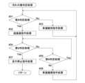
自動走行制御部23Fは、情報統合処理部80Cからの障害物検出情報に基づいて障害物との衝突を回避する衝突回避制御を実行する。
具体的には、自動走行制御部23Fは、情報統合処理部80Cからの適正情報出力処理又は準適正情報出力処理による障害物検出情報を取得した場合は、衝突回避制御として第1衝突回避制御を実行する。自動走行制御部23Fは、情報統合処理部80Cからのカメラ情報出力処理による障害物検出情報を取得した場合は、衝突回避制御として、第1衝突回避制御よりも衝突回避率の高い第2衝突回避制御を実行する。
The automatictravel control unit 23F executes collision avoidance control to avoid a collision with an obstacle based on the obstacle detection information from the informationintegration processing unit 80C.
Specifically, when the automaticdriving control unit 23F acquires the obstacle detection information through the appropriate information output processing or the semi-appropriate information output processing from the informationintegration processing unit 80C, the automaticdriving control unit 23F performs the first collision avoidance control as the collision avoidance control. Execute. When the automaticdriving control unit 23F acquires the obstacle detection information through the camera information output processing from the informationintegration processing unit 80C, the automaticdriving control unit 23F performs a second collision avoidance control, which has a higher collision avoidance rate than the first collision avoidance control, as collision avoidance control. Execute control.

以下、図22に示すフローチャートに基づいて、第1衝突回避制御における自動走行制御部23Fの制御作動について説明する。
尚、ここでは、前ライダーセンサ86の第1検出範囲Rd1に障害物が位置する場合を例示して説明する。
Hereinafter, the control operation of the automatictravel control section 23F in the first collision avoidance control will be explained based on the flowchart shown in FIG. 22.
Here, a case where an obstacle is located in the first detection range Rd1 of thefront lidar sensor 86 will be described as an example.

自動走行制御部23Fは、障害物検出情報に含まれた障害物との距離に基づいて、障害物が、図4に示す第1検出範囲Rd1のうちの報知制御範囲Rncに位置しているか否かを判定する第5判定処理と、減速制御範囲Rdcに位置しているか否かを判定する第6判定処理と、停止制御範囲Rscに位置しているか否かを判定する第7判定処理とを行う(ステップ#21~23)。ここで、障害物検出情報に含められた障害物との距離について、適正情報出力処理にて出力される障害物との距離は、前ライダーセンサ86が測定した障害物候補Ocの距離情報となっている。これに対し、準適正情報出力処理にて出力される障害物との距離は、前ライダーセンサ86が測定した障害物Oの周辺に位置する測定対象物Omの距離情報となっている。 The automatictravel control unit 23F determines whether the obstacle is located in the notification control range Rnc of the first detection range Rd1 shown in FIG. 4 based on the distance to the obstacle included in the obstacle detection information. A fifth determination process for determining whether the vehicle is located in the deceleration control range Rdc, a sixth determination process for determining whether the vehicle is located in the deceleration control range Rdc, and a seventh determination process for determining whether the vehicle is located in the stop control range Rsc. (Steps #21-23). Here, regarding the distance to the obstacle included in the obstacle detection information, the distance to the obstacle output in the appropriate information output process is the distance information of the obstacle candidate Oc measured by thefront lidar sensor 86. ing. On the other hand, the distance to the obstacle output in the semi-appropriate information output process is the distance information of the measurement object Om located around the obstacle O measured by thefront lidar sensor 86.

自動走行制御部23Fは、第5判定処理にて第1検出範囲Rd1の報知制御範囲Rncに障害物が位置することを検知した場合は、報知制御範囲Rncに障害物が位置することを、トラクタ1の液晶モニタ27や携帯通信端末5の表示デバイス50にて報知させるための報知指令を、車載制御ユニット23の表示制御部23Eと端末制御ユニット51の表示制御部51Aとに指令する第1報知指令処理を行う(ステップ#24)。
これにより、トラクタ1に対する第1検出範囲Rd1の報知制御範囲Rncに障害物が位置することを、運転部12の搭乗者や車外の管理者などのユーザに知らせることができる。
If the automatictravel control unit 23F detects in the fifth determination process that an obstacle is located in the notification control range Rnc of the first detection range Rd1, the automatictravel control unit 23F detects that the obstacle is located in the notification control range Rnc. A first notification that instructs thedisplay control section 23E of the on-vehicle control unit 23 and thedisplay control section 51A of theterminal control unit 51 to issue a notification command to be notified on the LCD monitor 27 of themobile communication terminal 1 and thedisplay device 50 of themobile communication terminal 5. Command processing is performed (step #24).
Thereby, it is possible to notify users such as the occupant of the drivingsection 12 and the administrator outside the vehicle that an obstacle is located in the notification control range Rnc of the first detection range Rd1 for thetractor 1.

自動走行制御部23Fは、第6判定処理にて第1検出範囲Rd1の減速制御範囲Rdcに障害物が位置することを検知した場合は、減速制御範囲Rdcに障害物が位置することを、トラクタ1の液晶モニタ27や携帯通信端末5の表示デバイス50にて報知させるための報知指令を、車載制御ユニット23の表示制御部23Eと端末制御ユニット51の表示制御部51Aとに指令する第2報知指令処理を行う(ステップ#25)。又、自動走行制御部23Fは、減速制御範囲Rdcに位置する障害物がトラクタ1に近づくほどトラクタ1の車速を低下させるための減速指令を車速制御部23Bに指令する減速指令処理を行う(ステップ#26)。
これにより、トラクタ1に対する第1検出範囲Rd1の減速制御範囲Rdcに障害物が位置することを、運転部12の搭乗者や車外の管理者などのユーザに知らせることができる。又、車速制御部23Bの制御作動により、トラクタ1が障害物に近づくに連れてトラクタ1の車速を適正に低下させることができる。
If the automatictravel control unit 23F detects in the sixth determination process that an obstacle is located in the deceleration control range Rdc of the first detection range Rd1, the automatictravel control unit 23F detects that the obstacle is located in the deceleration control range Rdc. 1 and thedisplay device 50 of themobile communication terminal 5 to thedisplay control section 23E of the on-vehicle control unit 23 and thedisplay control section 51A of theterminal control unit 51. Command processing is performed (step #25). The automatictravel control unit 23F also performs a deceleration command process in which the vehiclespeed control unit 23B is commanded to issue a deceleration command to reduce the vehicle speed of thetractor 1 as the obstacle located in the deceleration control range Rdc approaches the tractor 1 (step #26).
Thereby, it is possible to notify users such as the occupant of the drivingsection 12 and the administrator outside the vehicle that an obstacle is located in the deceleration control range Rdc of the first detection range Rd1 for thetractor 1. Moreover, the vehicle speed of thetractor 1 can be appropriately reduced as thetractor 1 approaches an obstacle by the control operation of the vehiclespeed control section 23B.

自動走行制御部23Fは、第7判定処理にて第1検出範囲Rd1の停止制御範囲Rscに障害物が位置することを検知した場合は、停止制御範囲Rscに障害物が位置することを、トラクタ1の液晶モニタ27や携帯通信端末5の表示デバイス50にて報知させるための報知指令を、車載制御ユニット23の表示制御部23Eと端末制御ユニット51の表示制御部51Aとに指令する第3報知指令処理を行う(ステップ#27)。又、自動走行制御部23Fは、障害物が停止制御範囲Rscに位置する間にトラクタ1を減速停止させるための減速停止指令を車速制御部23Bに指令する減速停止指令処理を行う(ステップ#28)。
これにより、トラクタ1に対する第1検出範囲Rd1の停止制御範囲Rscに障害物が位置することを、運転部12の搭乗者や車外の管理者などのユーザに知らせることができる。又、車速制御部23Bの制御作動により、障害物が停止制御範囲Rscに位置する間においてトラクタ1を減速停止させることができ、よって、トラクタ1が障害物に衝突する虞を回避することができる。
When the automatictravel control unit 23F detects in the seventh determination process that an obstacle is located in the stop control range Rsc of the first detection range Rd1, the automatictravel control unit 23F detects that the obstacle is located in the stop control range Rsc. A third notification that instructs thedisplay control section 23E of the on-vehicle control unit 23 and thedisplay control section 51A of theterminal control unit 51 to issue a notification command to thedisplay control section 23E of the in-vehicle control unit 23 and thedisplay control section 51A of theterminal control unit 51 to make notification on the LCD monitor 27 of themobile communication terminal 5 and thedisplay device 50 of themobile communication terminal 5. Command processing is performed (step #27). Further, the automatictravel control unit 23F performs deceleration and stop command processing to instruct the vehiclespeed control unit 23B to decelerate and stop thetractor 1 while the obstacle is located within the stop control range Rsc (step #28 ).
Thereby, it is possible to notify users such as the occupant of the drivingsection 12 and the administrator outside the vehicle that an obstacle is located within the stop control range Rsc of the first detection range Rd1 for thetractor 1. Furthermore, the control operation of the vehiclespeed control unit 23B allows thetractor 1 to be decelerated and stopped while the obstacle is located within the stop control range Rsc, thereby making it possible to avoid the possibility that thetractor 1 will collide with the obstacle. .

次に、第2衝突回避制御における自動走行制御部23Fの制御作動について説明すると、自動走行制御部23Fは、前述した第1衝突回避制御の場合よりも、前述した第1検出範囲Rd1の判定基準位置から減速制御範囲Rdcと停止制御範囲Rscとの境界までの距離、及び、判定基準位置から報知制御範囲Rncと減速制御範囲Rdcとの境界までの距離が長くなるように、減速制御範囲Rdc及び停止制御範囲Rscの前後長さを長くした状態で、第1衝突回避制御におけるステップ#21~28の制御処理と同じ制御処理を行う。これにより、第2衝突回避制御は、第1衝突回避制御よりも早いタイミングで障害物との衝突を回避するための衝突回避制御となっている。 Next, to explain the control operation of the automatictravel control unit 23F in the second collision avoidance control, the automatictravel control unit 23F uses the determination criteria of the first detection range Rd1 as described above, compared to the case of the first collision avoidance control described above. The deceleration control range Rdc and The same control processing as that of steps #21 to #28 in the first collision avoidance control is performed with the longitudinal length of the stop control range Rsc being increased. Thereby, the second collision avoidance control is a collision avoidance control for avoiding a collision with an obstacle at an earlier timing than the first collision avoidance control.

これにより、自動走行制御部23Fは、アクティブセンサユニット80Bからの測定情報よりも測距精度が低い撮像ユニット80Aからの測定情報に基づいて障害物との衝突を回避する第2衝突回避制御においては、第1衝突回避制御よりも衝突回避率を高めた状態で障害物との衝突を回避する。その結果、測距精度が低い撮像ユニット80Aからの測定情報に基づく障害物との衝突回避を良好に行うことができる。 As a result, the automatictravel control unit 23F performs the second collision avoidance control to avoid a collision with an obstacle based on the measurement information from theimaging unit 80A, which has lower distance measurement accuracy than the measurement information from theactive sensor unit 80B. , a collision with an obstacle is avoided with a higher collision avoidance rate than in the first collision avoidance control. As a result, collisions with obstacles can be effectively avoided based on the measurement information from theimaging unit 80A, which has low ranging accuracy.

自動走行制御部23Fの自動走行制御には、各ライダーセンサ86,87のセンサ表面に汚れの付着を検知した場合に、トラクタ1の自動走行を停止させる汚れ付着判定処理が含まれている。 The automatic travel control of the automatictravel control unit 23F includes a dirt adhesion determination process that stops automatic travel of thetractor 1 when dirt is detected on the sensor surface of eachrider sensor 86, 87.

以下、図23に示すフローチャートに基づいて、汚れ(測定阻害物)付着判定処理における自動走行制御部23Fの制御作動について説明する。
尚、ここでも、前ライダーセンサ86の場合を例示して説明する。
Hereinafter, based on the flowchart shown in FIG. 23, the control operation of the automatictravel control unit 23F in the dirt (measurement obstructing substance) adhesion determination process will be described.
Here, the case of thefront lidar sensor 86 will be explained as an example.

自動走行制御部23Fは、前ライダーセンサ86の測定範囲Rm1に対してライダーセンサ86からの測定情報に含まれている、汚れなどの測定阻害物に起因した無効値の占める割合が50%以上か否かを判定する第8判定処理を行う(ステップ#31)。 The automaticdriving control unit 23F determines whether the ratio of invalid values caused by measurement obstructions such as dirt, included in the measurement information from thelidar sensor 86, to the measurement range Rm1 of thefront lidar sensor 86 is 50% or more. An eighth determination process is performed to determine whether or not (step #31).

自動走行制御部23Fは、第8判定処理にて無効値の占める割合が50%以上である場合(事前に設定された汚れ付着判定用の所定条件を満たした場合)は、トラクタ1の車速を、トラクタ1の超低速走行状態を維持することが可能な超低速まで低下させるための超減速指令を車速制御部23Bに指令する超減速指令処理を行う(ステップ#32)。 If the ratio of invalid values is 50% or more in the eighth determination process (if a predetermined condition for determining dirt adhesion is satisfied), the automaticdriving control unit 23F adjusts the vehicle speed of thetractor 1. , a super deceleration command process is performed in which the vehiclespeed control unit 23B is given a super deceleration command to reduce the speed of thetractor 1 to a super low speed that can maintain the super low speed running state (step #32).

自動走行制御部23Fは、第8判定処理にて無効値の占める割合が50%以上でない場合は、トラクタ1の車速を、現在の車速に維持するための車速維持指令を車速制御部23Bに指令する車速維持指令処理を行う(ステップ#33)。 If the ratio of invalid values is not 50% or more in the eighth determination process, the automaticdriving control unit 23F instructs the vehiclespeed control unit 23B to issue a vehicle speed maintenance command to maintain the vehicle speed of thetractor 1 at the current vehicle speed. A vehicle speed maintenance command process is performed (step #33).

自動走行制御部23Fは、超減速指令処理を行った後、トラクタ1の超低速走行状態が所定時間継続されたか否かを判定する第9判定処理を行う(ステップ#34)。そして、自動走行制御部23Fは、超低速走行状態が所定時間継続されるまでの間において前述した第8判定処理を行い(ステップ#35)、この第8判定処理にて無効値の占める割合が50%未満に低下した場合は、前ライダーセンサ86のセンサ表面に汚れが付着しているのではなく、前ライダーセンサ86の周辺にて埃や霧などの浮遊物が舞っていただけであると判定して、トラクタ1の車速を、超低速まで低下させる前の元の車速に復帰させるための車速復帰指令を車速制御部23Bに指令する車速復帰指令処理を行い(ステップ#36)、その後、ステップ#31に戻る。 After performing the super deceleration command process, the automatictravel control unit 23F performs a ninth determination process to determine whether the extremely low speed traveling state of thetractor 1 has been continued for a predetermined period of time (step #34). Then, the automaticdriving control unit 23F performs the eighth determination process described above until the ultra-low speed driving state continues for a predetermined time (step #35), and in this eighth determination process, the proportion of invalid values is If it drops to less than 50%, it is determined that there is no dirt attached to the sensor surface of thefront lidar sensor 86, but that floating objects such as dust and fog are floating around thefront lidar sensor 86. Then, a vehicle speed return command process is performed to instruct the vehiclespeed control unit 23B to return the vehicle speed of thetractor 1 to the original vehicle speed before the vehicle speed was reduced to an extremely low speed (step #36). Return to #31.

自動走行制御部23Fは、超低速走行状態が所定時間継続された場合は、前ライダーセンサ86のセンサ表面に汚れが付着していると判定して、直ちにトラクタ1を走行停止させるための走行停止指令を車速制御部23Bに指令する走行停止指令処理を行う(ステップ#37)。 If the ultra-low speed running state continues for a predetermined period of time, the automatictravel control unit 23F determines that dirt has adhered to the sensor surface of thefront rider sensor 86, and immediately stops thetractor 1 from traveling. Running stop command processing is performed to issue a command to the vehiclespeed control unit 23B (step #37).

以上の構成により、自動走行制御部23Fの自動走行制御にてトラクタ1が自動走行している場合において、障害物検出ユニット80が、各カメラ81~84の情報から障害物を検出し、かつ、その障害物との離隔距離を前後のライダーセンサ86,87又はソナー88の情報から取得している場合は、自動走行制御部23Fが、前後のライダーセンサ86,87又はソナー88の情報から取得した障害物との離隔距離に基づいて、第1衝突回避制御を実行してトラクタ1と障害物との衝突を回避する。 With the above configuration, when thetractor 1 is automatically traveling under the automatic traveling control of the automatictraveling control section 23F, theobstacle detection unit 80 detects an obstacle from the information of eachcamera 81 to 84, and If the distance from the obstacle is acquired from the information of the front andrear lidar sensors 86, 87 orsonar 88, the automatictravel control unit 23F acquires the distance from the front andrear lidar sensors 86, 87 orsonar 88. Based on the separation distance from the obstacle, first collision avoidance control is executed to avoid a collision between thetractor 1 and the obstacle.

つまり、障害物検出ユニット80は、物体判別精度の高い各カメラ81~84の情報から、作業地に存在する人物や樹木などを障害物として精度よく検出することができる。又、障害物検出ユニット80は、その検出した人物や樹木などの障害物との離隔距離を測距精度の高い前後のライダーセンサ86,87又はソナー88の情報から高い精度で取得することができる。これにより、障害物検出ユニット80は前述した適正検出状態となる。そして、自動走行制御部23Fは、前後のライダーセンサ86,87又はソナー88の情報から取得した精度の高い人物や樹木などの障害物との離隔距離に基づいて、それらの障害物にトラクタ1が衝突する虞を精度よく回避することができる。 In other words, theobstacle detection unit 80 can accurately detect people, trees, etc. existing in the work area as obstacles based on the information from thecameras 81 to 84, which have high object discrimination accuracy. Further, theobstacle detection unit 80 can obtain the distance from the detected obstacle such as a person or tree with high accuracy from information from front andrear lidar sensors 86, 87 orsonar 88, which have high distance measurement accuracy. . As a result, theobstacle detection unit 80 enters the proper detection state described above. Then, the automatictravel control unit 23F determines whether thetractor 1 is close to the obstacles, such as people or trees, based on the highly accurate separation distances from the obstacles, such as people or trees, acquired from the information of the front andrear lidar sensors 86, 87 or thesonar 88. The possibility of collision can be avoided with high precision.

その結果、障害物を精度良く検出することができる上に、トラクタ1が不必要な衝突回避動作を行うことなく障害物との衝突を精度よく回避させることができる。 As a result, not only can obstacles be detected with high precision, but also thetractor 1 can avoid collisions with obstacles with high precision without performing unnecessary collision avoidance operations.

又、障害物検出ユニット80が、各カメラ81~84の情報から障害物を検出しているのに対し、その障害物との離隔距離を前後のライダーセンサ86,87又はソナー88から取得することができない場合(前述した単独検出状態)は、自動走行制御部23Fが、各カメラ81~84の情報から取得した障害物との離隔距離に基づいて、第1衝突回避制御よりも衝突回避率の高い第2衝突回避制御を実行する。 Further, while theobstacle detection unit 80 detects obstacles from information from each of thecameras 81 to 84, the distance from the obstacle can be obtained from the front andrear lidar sensors 86, 87 or thesonar 88. If this is not possible (the above-mentioned single detection state), the automatictravel control unit 23F will control the collision avoidance rate higher than the first collision avoidance control based on the separation distance from the obstacle obtained from the information of eachcamera 81 to 84. Execute high second collision avoidance control.

これにより、自動走行制御部23Fは、例えば各ライダーセンサ86,87などのセンサ表面に汚れなどの測定阻害物が付着することや、各ライダーセンサ86,87などの周辺にて埃や塵埃などの測定阻害物が舞い上がることに起因して、障害物との離隔距離を各ライダーセンサ86,87などの情報から取得することができない場合であっても、各カメラ81~84の情報から取得する障害物との離隔距離に基づいて、トラクタ1が障害物に衝突する虞を回避することができる。 As a result, the automatictravel control unit 23F is able to prevent measurement obstructions such as dirt from adhering to the sensor surfaces of thelidar sensors 86 and 87, and dust and dirt around thelidar sensors 86 and 87. Even if the separation distance from the obstacle cannot be obtained from the information of eachlidar sensor 86, 87 due to the measurement obstacle flying up, the obstacle is obtained from the information of eachcamera 81 to 84. Based on the separation distance from the object, it is possible to avoid the possibility that thetractor 1 will collide with an obstacle.

又、各カメラ81~84の情報から取得する障害物との離隔距離は、各ライダーセンサ86,87又はソナー88の情報から取得する障害物との離隔距離よりも精度が低いことから、自動走行制御部23Fは、第1衝突回避制御よりも衝突回避率の高い第2衝突回避制御を実行することで、測距精度の低下を補いながら、トラクタ1が障害物に衝突する虞を好適に回避することができる。 Furthermore, since the distance to the obstacle obtained from the information of eachcamera 81 to 84 is less accurate than the distance to the obstacle obtained from the information of eachlidar sensor 86, 87 orsonar 88, automatic driving Thecontrol unit 23F appropriately avoids the possibility that thetractor 1 will collide with an obstacle while compensating for the decrease in ranging accuracy by executing the second collision avoidance control which has a higher collision avoidance rate than the first collision avoidance control. can do.

更に、障害物検出ユニット80が、各カメラ81~84の情報から障害物を検出しているのに対し、各ライダーセンサ86,87又はソナー88の情報からは障害物との離隔距離を取得することができずに、障害物周辺との離隔距離を取得している場合(前述した準適正検出状態)は、自動走行制御部23Fが、障害物検出ユニット80が取得した前記障害物周辺との離隔距離に基づいて第1衝突回避制御を実行する。 Furthermore, while theobstacle detection unit 80 detects obstacles from information from each of thecameras 81 to 84, it obtains the separation distance from the obstacle from information from eachlidar sensor 86, 87 orsonar 88. If the separation distance from the vicinity of the obstacle is acquired without being able to do so (the above-mentioned semi-appropriate detection state), the automatictravel control unit 23F determines the distance from the vicinity of the obstacle acquired by theobstacle detection unit 80. First collision avoidance control is executed based on the separation distance.

これにより、自動走行制御部23Fは、例えば各カメラ81~84の情報から検出した障害物が周辺の草などに紛れていることなどに起因して、その障害物との距離を各ライダーセンサ86,87又はソナー88が測定することができずに、その障害物の周辺に位置する草などの測定対象物との距離を測定している場合には、その障害物との離隔距離に略等しい障害物周辺の測定対象物との離隔距離に基づいて、トラクタ1が障害物に衝突する虞を回避することができる。その結果、トラクタ1が障害物に衝突する虞を比較的高い精度で回避することができる。 As a result, the automatictravel control unit 23F determines the distance to the obstacle detected by eachlidar sensor 86 from the information of each of thecameras 81 to 84, for example, due to the fact that the obstacle is hidden in the surrounding grass, etc. , 87 or thesonar 88 is unable to measure the distance to an object such as grass located around the obstacle, the distance is approximately equal to the distance from the obstacle. Based on the separation distance from the object to be measured around the obstacle, it is possible to avoid the possibility that thetractor 1 will collide with the obstacle. As a result, the possibility that thetractor 1 will collide with an obstacle can be avoided with relatively high accuracy.

その上、自動走行制御部23Fは、各ライダーセンサ86,87などのセンサ表面に対する汚れなどの測定阻害物の付着率(汚れなどの測定阻害物に起因した無効値の占める割合)が所定条件(50%以上)を満たした場合に、前記トラクタ1の車速を超低速状態まで低下させた超低速走行状態を所定時間継続する。そして、自動走行制御部23Fは、所定時間が経過するまでの間に付着率が所定条件を満たさなくなった場合は、トラクタ1の車速を超低速状態から元の車速に復帰させ、又、所定時間が経過するまでの間、付着率が所定条件を満たし続けた場合は、トラクタ1の自動走行を停止させる。 In addition, the automatictravel control unit 23F is configured such that the adhesion rate of measurement obstructions such as dirt to the sensor surface of eachlidar sensor 86, 87 (ratio of invalid values due to measurement obstructions such as dirt) is under a predetermined condition ( 50% or more), the vehicle speed of thetractor 1 is reduced to a very low speed state and continues for a predetermined period of time. Then, if the adhesion rate no longer satisfies the predetermined condition before the predetermined time elapses, the automatictravel control unit 23F returns the vehicle speed of thetractor 1 from the ultra-low speed state to the original vehicle speed, and If the adhesion rate continues to satisfy the predetermined condition until the time elapses, the automatic traveling of thetractor 1 is stopped.

これにより、単に、各ライダーセンサ86,87又はソナー88のセンサ表面に対する測定阻害物の付着率が所定条件を満たした場合にトラクタ1の自動走行を停止させるのではなく、付着率が所定条件を満たした状態が所定時間継続される条件を付加することで、所定条件を満たしている測定阻害物が、センサ表面に対する汚れなどの付着物か、各ライダーセンサ86,87又はソナー88の周辺にて舞い上がっている埃や塵埃などの浮遊物かを判定することができ、その判定結果に応じてトラクタ1の走行を制御することができる。 As a result, the automatic traveling of thetractor 1 is not simply stopped when the adhesion rate of measurement obstructions to the sensor surface of eachlidar sensor 86, 87 or thesonar 88 satisfies a predetermined condition, but the adhesion rate satisfies a predetermined condition. By adding a condition that continues to be satisfied for a predetermined period of time, it is possible to determine whether the measurement obstruction that satisfies the predetermined condition is due to dirt or other adhesion to the sensor surface, or around eachlidar sensor 86, 87 orsonar 88. It is possible to determine whether the flying object is a floating object such as dust or dirt, and the traveling of thetractor 1 can be controlled according to the determination result.

しかも、付着率が所定条件を満たしてから所定時間が経過するまでの間は、トラクタ1を超低速走行状態で走行させることから、単に低速走行状態で走行させる場合に比較して、付着率が所定条件を満たしてからの所定時間、つまり、付着物か否かの判定時間を長くすることができる。これにより、所定条件を満たしている測定阻害物が埃や塵埃などの浮遊物である場合に、トラクタ1が停止する不都合の発生を抑制することができる。 Moreover, since thetractor 1 is run at an extremely low speed until a predetermined time has elapsed after the adhesion rate satisfies a predetermined condition, the adhesion rate is lower than when thetractor 1 is simply run at a low speed. It is possible to lengthen the predetermined time after the predetermined condition is satisfied, that is, the time required to determine whether or not there is a deposit. Thereby, it is possible to suppress the occurrence of an inconvenience in which thetractor 1 stops when the measurement obstruction that satisfies the predetermined conditions is a floating object such as dust or dirt.

又、トラクタ1を超低速走行状態で走行させることで、付着物か否かの判定中にトラクタ1が障害物に衝突する不都合の発生を抑制することができる。 Furthermore, by running thetractor 1 at an extremely low speed, it is possible to suppress the occurrence of an inconvenience in which thetractor 1 collides with an obstacle while determining whether or not there is an attached object.

〔別実施形態〕
本発明の別実施形態について説明する。
尚、以下に説明する各別実施形態の構成は、それぞれ単独で適用することに限らず、他の別実施形態の構成と組み合わせて適用することも可能である。
[Another embodiment]
Another embodiment of the present invention will be described.
Note that the configurations of each of the different embodiments described below are not limited to being applied individually, but can also be applied in combination with the configurations of other different embodiments.

(1)作業車両の構成は種々の変更が可能である。
例えば、作業車両は、左右の後輪11に代えて左右のクローラを備えるセミクローラ仕様に構成されていてもよい。
例えば、作業車両は、左右の前輪10及び左右の後輪11に代えて左右のクローラを備えるフルクローラ仕様に構成されていてもよい。
例えば、作業車両は、エンジン14の代わりに電動モータを備える電動仕様に構成されていてもよい。
例えば、作業車両は、エンジン14と走行用の電動モータとを備えるハイブリッド仕様に構成されていてもよい。
(1) The configuration of the work vehicle can be modified in various ways.
For example, the work vehicle may be configured with semi-crawler specifications including left and right crawlers instead of the left and rightrear wheels 11.
For example, the work vehicle may be configured with a full crawler specification including left and right crawlers instead of the left and rightfront wheels 10 and the left and rightrear wheels 11.
For example, the work vehicle may be configured to be electrically powered, including an electric motor instead of theengine 14.
For example, the work vehicle may be configured with a hybrid specification including theengine 14 and an electric motor for driving.

(2)アクティブセンサ86~88として、ライダーセンサ86,87やソナー88に代えて、レーダーセンサを採用してもよい。又、全てのアクティブセンサ86~88にライダーセンサを採用してもよい。(2) As theactive sensors 86 to 88, radar sensors may be employed instead of thelidar sensors 86, 87 and thesonar 88. Furthermore, lidar sensors may be employed as all of theactive sensors 86 to 88.

(3)アクティブセンサ86~88は、それらの測定範囲Rm1~Rm4において画像処理装置85にて障害物が検出された場合に、障害物までの距離を測定するように構成されていてもよい。
この構成によると、アクティブセンサ86~88は、それらの測定範囲Rm1~Rm4での測定を常時行う必要がなく、それらの測定範囲Rm1~Rm4において画像処理装置85にて障害物が検知された場合にのみ、障害物までの距離を測定することから、測距に要する負荷の軽減を図りながら、障害物に対する測距の精度を高くすることができる。
(3) Theactive sensors 86 to 88 may be configured to measure the distance to the obstacle when theimage processing device 85 detects an obstacle in the measurement ranges Rm1 to Rm4.
According to this configuration, theactive sensors 86 to 88 do not need to constantly perform measurements in the measurement ranges Rm1 to Rm4, and when an obstacle is detected by theimage processing device 85 in the measurement ranges Rm1 to Rm4, Since the distance to the obstacle is measured only when the distance is measured, the accuracy of distance measurement to the obstacle can be increased while reducing the load required for distance measurement.

(4)撮像部81~84には、ステレオカメラなどを採用してもよい。
又、撮像部81~84として、前述した前カメラ81、後カメラ82、右カメラ83、左カメラ84に加えて、前カメラ81と画角の異なる前カメラを備えるようにしてもよい。
(4) A stereo camera or the like may be employed as theimaging units 81 to 84.
Furthermore, in addition to the aforementionedfront camera 81,rear camera 82,right camera 83, and leftcamera 84, theimaging units 81 to 84 may include a front camera having a different angle of view from thefront camera 81.

1 作業車両
23F 自動走行制御部
80 障害物検出ユニット
81 撮像部(前カメラ)
82 撮像部(後カメラ)
83 撮像部(右カメラ)
84 撮像部(左カメラ)
86 アクティブセンサ(前ライダーセンサ)
87 アクティブセンサ(後ライダーセンサ)
88 アクティブセンサ(ソナー)
O 障害物
Ri1 設定範囲(第1撮像範囲)
Ri2 設定範囲(第2撮像範囲)
Ri3 設定範囲(第3撮像範囲)
Ri4 設定範囲(第4撮像範囲)
Rm1 設定範囲(第1測定範囲)
Rm2 設定範囲(第2測定範囲)
Rm3 設定範囲(第3測定範囲)
Rm4 設定範囲(第4測定範囲)
1Work vehicle 23F Automatictravel control unit 80Obstacle detection unit 81 Imaging unit (front camera)
82 Imaging unit (rear camera)
83 Imaging unit (right camera)
84 Imaging unit (left camera)
86 Active sensor (front rider sensor)
87 Active sensor (rear rider sensor)
88 Active sensor (sonar)
O Obstacle Ri1 setting range (first imaging range)
Ri2 setting range (second imaging range)
Ri3 setting range (third imaging range)
Ri4 setting range (4th imaging range)
Rm1 Setting range (1st measurement range)
Rm2 setting range (second measurement range)
Rm3 setting range (third measurement range)
Rm4 Setting range (4th measurement range)

Claims (4)

Translated fromJapanese
障害物を検出する障害物検出ユニットが備えられた作業車両を自動走行させる自動走行制御部を有し、
前記障害物検出ユニットには、前記作業車両から所定方向の設定範囲を撮像する撮像部と、前記作業車両から前記撮像部と同じ所定方向の設定範囲を測定対象とするアクティブセンサとが含まれており、
前記障害物検出ユニットが、前記撮像部の情報から前記障害物を検出し、かつ、当該障害物との離隔距離を前記アクティブセンサの情報から取得している場合は、前記自動走行制御部が、前記アクティブセンサの情報から取得した前記障害物との離隔距離に基づいて、前記作業車両と前記障害物との衝突を回避する第1衝突回避制御を実行し、
前記障害物検出ユニットが、前記撮像部の情報から前記障害物を検出しているのに対し、当該障害物との離隔距離を前記アクティブセンサの情報から取得することができない場合は、前記自動走行制御部が、前記第1衝突回避制御よりも衝突を回避しやすい衝突回避制御を実行する作業車両用の自動走行システム。
It has an automatic travel control unit that automatically travels a work vehicle equipped with an obstacle detection unit that detects obstacles,
The obstacle detection unit includes an imaging section that images a set range in a predetermined direction from the work vehicle, and an active sensor that measures a set range from the work vehicle in the same predetermined direction as the imaging section. Ori,
When the obstacle detection unit detects the obstacle from the information of the imaging unit and acquires the separation distance from the obstacle from the information of the active sensor, the automatic travel control unit: Executing first collision avoidance control to avoid a collision between the work vehicle and the obstacle based on a separation distance from the obstacle obtained from information of the active sensor,
If the obstacle detection unit detects the obstacle from the information of the imaging unit, but cannot obtain the separation distance from the obstacle from the information of the active sensor, the automatic driving An automatic driving system for a work vehicle in which a control unit executes collision avoidance controlthat makes it easier to avoid a collision than the first collision avoidance control.
前記障害物検出ユニットが、前記撮像部の情報から前記障害物を検出しているのに対し、当該障害物との離隔距離を前記アクティブセンサの情報から取得することができない場合は、前記自動走行制御部が、前記撮像部の情報から取得した前記障害物との離隔距離に基づいて、前記第1衝突回避制御よりも衝突回避率の高い第2衝突回避制御を実行する請求項1に記載の作業車両用の自動走行システム。 If the obstacle detection unit detects the obstacle from the information of the imaging unit, but cannot obtain the separation distance from the obstacle from the information of the active sensor, the automatic driving The control unit executes second collision avoidance control having a higher collision avoidance rate than the first collision avoidance control based on the separation distance from the obstacle acquired from the information of the imaging unit. Automated driving system for work vehicles. 前記障害物検出ユニットが、前記撮像部の情報から前記障害物を検出しているのに対し、前記アクティブセンサの情報からは前記障害物との離隔距離を取得することができずに、前記障害物周辺との離隔距離を取得している場合は、前記自動走行制御部が、前記アクティブセンサが取得した前記障害物周辺との離隔距離に基づいて前記作業車両と前記障害物との衝突を回避する第3衝突回避制御を実行する請求項1又2に記載の作業車両用の自動走行システム。 While the obstacle detection unit detects the obstacle from the information of the imaging unit, it is not possible to obtain the separation distance from the obstacle from the information of the active sensor, and the obstacle is detected by the obstacle detection unit. If the distance from the vicinity of the object has been acquired, the automatic travel control unit avoids a collision between the work vehicle and the obstacle based on the distance from the vicinity of the obstacle acquired by the active sensor. The automatic driving system for a work vehicle according to claim 1 or 2, wherein the automatic driving system for a work vehicle executes third collision avoidance control. 前記自動走行制御部は、前記アクティブセンサに対する測定阻害物の付着率が所定条件を満たした場合に、前記作業車両の車速を超低速状態まで低下させた超低速走行状態を所定時間継続し、所定時間が経過するまでの間に前記付着率が前記所定条件を満たさなくなった場合は、前記作業車両の車速を超低速状態から元の車速に復帰させ、一方、所定時間が経過するまでの間、前記付着率が前記所定条件を満たし続けた場合は、前記作業車両の自動走行を停止させる請求項1~3のいずれか一項に記載の作業車両用の自動走行システム。 The automatic driving control unit is configured to continue an ultra-low-speed driving state in which the vehicle speed of the work vehicle is reduced to an ultra-low speed state for a predetermined period of time, when a measurement obstructive adhesion rate to the active sensor satisfies a predetermined condition. If the adhesion rate no longer satisfies the predetermined condition before the time elapses, the vehicle speed of the work vehicle is returned from the ultra-low speed state to the original vehicle speed, and on the other hand, until the predetermined time elapses, The automatic travel system for a work vehicle according to any one of claims 1 to 3, wherein automatic travel of the work vehicle is stopped if the adhesion rate continues to satisfy the predetermined condition.
JP2019128308A2019-07-102019-07-10 Automated driving system for work vehiclesActiveJP7349277B2 (en)

Priority Applications (6)

Application NumberPriority DateFiling DateTitle
JP2019128308AJP7349277B2 (en)2019-07-102019-07-10 Automated driving system for work vehicles
US17/625,810US20230221728A1 (en)2019-07-102020-07-09Automatic Travel System for Work Vehicle
PCT/JP2020/026932WO2021006322A1 (en)2019-07-102020-07-09Automatic travel system for work vehicle
KR1020217035910AKR20220031542A (en)2019-07-102020-07-09 Automated driving systems for work vehicles
CN202080049400.5ACN114080578A (en)2019-07-102020-07-09 Automated travel systems for work vehicles
EP20837622.8AEP3997973B1 (en)2019-07-102020-07-09Automatic travel system for work vehicle

Applications Claiming Priority (1)

Application NumberPriority DateFiling DateTitle
JP2019128308AJP7349277B2 (en)2019-07-102019-07-10 Automated driving system for work vehicles

Publications (2)

Publication NumberPublication Date
JP2021015340A JP2021015340A (en)2021-02-12
JP7349277B2true JP7349277B2 (en)2023-09-22

Family

ID=74114530

Family Applications (1)

Application NumberTitlePriority DateFiling Date
JP2019128308AActiveJP7349277B2 (en)2019-07-102019-07-10 Automated driving system for work vehicles

Country Status (6)

CountryLink
US (1)US20230221728A1 (en)
EP (1)EP3997973B1 (en)
JP (1)JP7349277B2 (en)
KR (1)KR20220031542A (en)
CN (1)CN114080578A (en)
WO (1)WO2021006322A1 (en)

Families Citing this family (12)

* Cited by examiner, † Cited by third party
Publication numberPriority datePublication dateAssigneeTitle
US10795351B2 (en)*2016-07-192020-10-06Raven Industries, Inc.System and method for autonomous control of agricultural machinery and equipment
JP7446921B2 (en)*2020-05-292024-03-11株式会社東芝 Moving object, distance measurement method, and distance measurement program
JP7179116B2 (en)*2021-04-142022-11-28日立建機株式会社 Transportation vehicles and transportation systems
US12276985B2 (en)*2021-09-302025-04-15Zimeno Inc.Obstruction avoidance
JPWO2023119996A1 (en)*2021-12-242023-06-29
GB202214262D0 (en)*2022-09-292022-11-16Agco Int GmbhDefining alert zones for agricultural vehicle
KR102572851B1 (en)*2023-04-042023-08-31주식회사 클로봇Mobile robot device for moving to destination and operation method thereof
CN117016069A (en)*2023-08-152023-11-10湖南农业大学Land leveler with automatically adjustable left-right distance for rotary cultivator and adjusting method thereof
US20250083841A1 (en)*2023-09-112025-03-13Polaris Industries Inc.Drone integration with vehicle
US20250089593A1 (en)*2023-09-142025-03-20Cnh Industrial America LlcSteering slop compensation system for an agricultural vehicle
KR20250062801A (en)*2023-10-312025-05-08현대자동차주식회사Apparatus for controlling autonomous driving and method thereof
DE102023130883A1 (en)*2023-11-082025-05-08Claas Kommanditgesellschaft auf Aktien mbH Agricultural work machine

Citations (5)

* Cited by examiner, † Cited by third party
Publication numberPriority datePublication dateAssigneeTitle
JP2007078476A (en)2005-09-132007-03-29Toshiba Corp Object position detection device, map creation device, autonomous mobile device, object position detection method, and object position detection program
US20120083982A1 (en)2010-10-052012-04-05Zachary Thomas BonefasSystem and method for governing a speed of an autonomous vehicle
JP2016024685A (en)2014-07-222016-02-08日立建機株式会社Work vehicle for mine
JP2017156177A (en)2016-02-292017-09-07パナソニックIpマネジメント株式会社 Obstacle detection device and obstacle detection method
JP2018120421A (en)2017-01-252018-08-02シャープ株式会社 Traveling device

Family Cites Families (8)

* Cited by examiner, † Cited by third party
Publication numberPriority datePublication dateAssigneeTitle
US20100066587A1 (en)*2006-07-142010-03-18Brian Masao YamauchiMethod and System for Controlling a Remote Vehicle
JP5160370B2 (en)*2008-10-152013-03-13株式会社Ihi Autonomous mobile robot device, mobile body steering assist device, autonomous mobile robot device control method, and mobile body steering assist method
JP5722127B2 (en)2011-06-072015-05-20株式会社小松製作所 Work vehicle perimeter monitoring device
JP6247904B2 (en)*2013-11-082017-12-13日立建機株式会社 Mine transport vehicle
JP2016028311A (en)*2014-07-102016-02-25株式会社リコーRobot, program, and recording medium
US11449059B2 (en)*2017-05-012022-09-20Symbol Technologies, LlcObstacle detection for a mobile automation apparatus
US10794992B2 (en)*2017-07-182020-10-06Veoneer Us, Inc.Apparatus and method for detecting and correcting for blockage of an automotive radar sensor
US11163309B2 (en)*2017-11-302021-11-02Direct Current Capital LLCMethod for autonomous navigation

Patent Citations (5)

* Cited by examiner, † Cited by third party
Publication numberPriority datePublication dateAssigneeTitle
JP2007078476A (en)2005-09-132007-03-29Toshiba Corp Object position detection device, map creation device, autonomous mobile device, object position detection method, and object position detection program
US20120083982A1 (en)2010-10-052012-04-05Zachary Thomas BonefasSystem and method for governing a speed of an autonomous vehicle
JP2016024685A (en)2014-07-222016-02-08日立建機株式会社Work vehicle for mine
JP2017156177A (en)2016-02-292017-09-07パナソニックIpマネジメント株式会社 Obstacle detection device and obstacle detection method
JP2018120421A (en)2017-01-252018-08-02シャープ株式会社 Traveling device

Also Published As

Publication numberPublication date
CN114080578A (en)2022-02-22
JP2021015340A (en)2021-02-12
US20230221728A1 (en)2023-07-13
EP3997973A1 (en)2022-05-18
EP3997973B1 (en)2024-09-04
WO2021006322A1 (en)2021-01-14
KR20220031542A (en)2022-03-11
EP3997973A4 (en)2023-07-05

Similar Documents

PublicationPublication DateTitle
JP7349277B2 (en) Automated driving system for work vehicles
JP7044694B2 (en) Obstacle detection system for work vehicles
JP7526333B2 (en) Automatic driving system for work vehicle and control method for work vehicle
JP7402608B2 (en) Collision avoidance system for work vehicles
JP7657542B2 (en) Obstacle Detection System
US11805720B2 (en)Automatic travel system for work vehicle
JP7399680B2 (en) Work support system
WO2022065091A1 (en)Automatic traveling system, automatic traveling method, and automatic traveling program
JP2023126466A (en)Automatic traveling method and automatic traveling system
JP7317165B2 (en) Obstacle detection system for work vehicles
JP7544778B2 (en) Autonomous driving system for work vehicles
JP7059221B2 (en) Control system for work vehicles
JP7317169B2 (en) Control system for work vehicles
JP2025156384A (en) Automated driving system and automated driving method

Legal Events

DateCodeTitleDescription
RD03Notification of appointment of power of attorney

Free format text:JAPANESE INTERMEDIATE CODE: A7423

Effective date:20200814

A621Written request for application examination

Free format text:JAPANESE INTERMEDIATE CODE: A621

Effective date:20220225

A131Notification of reasons for refusal

Free format text:JAPANESE INTERMEDIATE CODE: A131

Effective date:20221213

A521Request for written amendment filed

Free format text:JAPANESE INTERMEDIATE CODE: A523

Effective date:20230125

A131Notification of reasons for refusal

Free format text:JAPANESE INTERMEDIATE CODE: A131

Effective date:20230509

A521Request for written amendment filed

Free format text:JAPANESE INTERMEDIATE CODE: A523

Effective date:20230621

TRDDDecision of grant or rejection written
A01Written decision to grant a patent or to grant a registration (utility model)

Free format text:JAPANESE INTERMEDIATE CODE: A01

Effective date:20230905

A61First payment of annual fees (during grant procedure)

Free format text:JAPANESE INTERMEDIATE CODE: A61

Effective date:20230911

R150Certificate of patent or registration of utility model

Ref document number:7349277

Country of ref document:JP

Free format text:JAPANESE INTERMEDIATE CODE: R150


[8]ページ先頭

©2009-2025 Movatter.jp