JP7348239B2 - Surgical instrument with ultrasound tip for fibrous tissue removal - Google Patents
Surgical instrument with ultrasound tip for fibrous tissue removalDownload PDFInfo
- Publication number
- JP7348239B2 JP7348239B2JP2021126504AJP2021126504AJP7348239B2JP 7348239 B2JP7348239 B2JP 7348239B2JP 2021126504 AJP2021126504 AJP 2021126504AJP 2021126504 AJP2021126504 AJP 2021126504AJP 7348239 B2JP7348239 B2JP 7348239B2
- Authority
- JP
- Japan
- Prior art keywords
- cutting edge
- circumferential surface
- vibration
- tissue
- head portion
- Prior art date
- Legal status (The legal status is an assumption and is not a legal conclusion. Google has not performed a legal analysis and makes no representation as to the accuracy of the status listed.)
- Active
Links
- 238000002604ultrasonographyMethods0.000titledescription61
- 230000007246mechanismEffects0.000claimsdescription22
- 238000006243chemical reactionMethods0.000claimsdescription7
- 239000002131composite materialSubstances0.000claimsdescription5
- 230000001154acute effectEffects0.000claimsdescription2
- 230000002093peripheral effectEffects0.000claims1
- 210000001519tissueAnatomy0.000description62
- 238000002679ablationMethods0.000description18
- 230000008901benefitEffects0.000description13
- 206010028980NeoplasmDiseases0.000description10
- 238000000034methodMethods0.000description10
- 230000007704transitionEffects0.000description7
- 239000000835fiberSubstances0.000description6
- 238000001356surgical procedureMethods0.000description6
- 239000011248coating agentSubstances0.000description5
- 238000000576coating methodMethods0.000description5
- 230000002262irrigationEffects0.000description4
- 238000003973irrigationMethods0.000description4
- 238000002271resectionMethods0.000description3
- 229910001069Ti alloyInorganic materials0.000description2
- NRTOMJZYCJJWKI-UHFFFAOYSA-NTitanium nitrideChemical compound[Ti]#NNRTOMJZYCJJWKI-UHFFFAOYSA-N0.000description2
- 239000012530fluidSubstances0.000description2
- 230000013011matingEffects0.000description2
- 239000007769metal materialSubstances0.000description2
- 230000000737periodic effectEffects0.000description2
- 210000004872soft tissueAnatomy0.000description2
- 230000002463transducing effectEffects0.000description2
- 241000473391Archosargus rhomboidalisSpecies0.000description1
- 210000003484anatomyAnatomy0.000description1
- 210000000988bone and boneAnatomy0.000description1
- 210000004556brainAnatomy0.000description1
- 230000006378damageEffects0.000description1
- 208000018212fibroblastic neoplasmDiseases0.000description1
- 230000006872improvementEffects0.000description1
- 239000000463materialSubstances0.000description1
- 239000002184metalSubstances0.000description1
- 229910052751metalInorganic materials0.000description1
- 150000002739metalsChemical class0.000description1
- 230000004048modificationEffects0.000description1
- 238000012986modificationMethods0.000description1
- 230000037361pathwayEffects0.000description1
- 230000035515penetrationEffects0.000description1
- 230000009467reductionEffects0.000description1
- 230000035939shockEffects0.000description1
- 210000000278spinal cordAnatomy0.000description1
- 239000010935stainless steelSubstances0.000description1
- 229910001220stainless steelInorganic materials0.000description1
Images


Classifications
- A—HUMAN NECESSITIES
- A61—MEDICAL OR VETERINARY SCIENCE; HYGIENE
- A61B—DIAGNOSIS; SURGERY; IDENTIFICATION
- A61B17/00—Surgical instruments, devices or methods
- A61B17/32—Surgical cutting instruments
- A61B17/320068—Surgical cutting instruments using mechanical vibrations, e.g. ultrasonic
- A—HUMAN NECESSITIES
- A61—MEDICAL OR VETERINARY SCIENCE; HYGIENE
- A61B—DIAGNOSIS; SURGERY; IDENTIFICATION
- A61B17/00—Surgical instruments, devices or methods
- A61B17/32—Surgical cutting instruments
- A61B17/320068—Surgical cutting instruments using mechanical vibrations, e.g. ultrasonic
- A61B2017/320072—Working tips with special features, e.g. extending parts
- A61B2017/320078—Tissue manipulating surface
- A—HUMAN NECESSITIES
- A61—MEDICAL OR VETERINARY SCIENCE; HYGIENE
- A61B—DIAGNOSIS; SURGERY; IDENTIFICATION
- A61B17/00—Surgical instruments, devices or methods
- A61B17/32—Surgical cutting instruments
- A61B17/320068—Surgical cutting instruments using mechanical vibrations, e.g. ultrasonic
- A61B2017/320098—Surgical cutting instruments using mechanical vibrations, e.g. ultrasonic with transverse or torsional motion
Landscapes
- Health & Medical Sciences (AREA)
- Surgery (AREA)
- Engineering & Computer Science (AREA)
- Life Sciences & Earth Sciences (AREA)
- Heart & Thoracic Surgery (AREA)
- Nuclear Medicine, Radiotherapy & Molecular Imaging (AREA)
- Mechanical Engineering (AREA)
- Biomedical Technology (AREA)
- Dentistry (AREA)
- Medical Informatics (AREA)
- Molecular Biology (AREA)
- Animal Behavior & Ethology (AREA)
- General Health & Medical Sciences (AREA)
- Public Health (AREA)
- Veterinary Medicine (AREA)
- Surgical Instruments (AREA)
- Dental Tools And Instruments Or Auxiliary Dental Instruments (AREA)
Description
Translated fromJapanese[関連出願の相互参照]
本願は、2015年6月17日に出願された米国仮特許出願第62/180,656号
の利得を主張するものであり、その開示内容の全体が、参照することによって、ここに含
まれるものとする。[Cross reference to related applications]
This application claims the benefit of U.S. Provisional Patent Application No. 62/180,656, filed June 17, 2015, the entire disclosure of which is hereby incorporated by reference. shall be.
[発明の分野]
本発明は、一般的に、外科器具に関し、さらに詳細には、超音波チップ及び患者に用い
られる線維組織除去のための該超音波チップを有する外科器具に関する。[Field of invention]
TECHNICAL FIELD This invention relates generally to surgical instruments, and more particularly to an ultrasound tip and a surgical instrument having the ultrasound tip for use in a patient for fibrous tissue removal.
医療施術者は、ある特定の外科処置の遂行を助長するために超音波外科器具を用いるの
が有用であることを見出している。超音波外科器具は、患者の外科部位に適用されるよう
に設計されている。施術者は、超音波外科器具を該器具が医療又は外科処置を行うべき患
者の部位に位置決めすることになる。一般的に、超音波外科器具は、少なくとも1つの圧
電ドライバを含む超音波ハンドピースを備えている。超音波チップは、現在利用可能な外
科器具によって除去することが困難な組織、特に、線維性、弾性、粘性、及び靭性を有す
る腫瘍組織を除去するために、超音波ハンドピースと併せて用いられている。少なくとも
一形式の外科処置において、外科医は、腫瘍組織を正確に除去するために超音波外科器具
を用いている。Medical practitioners have found it useful to use ultrasonic surgical instruments to aid in the performance of certain surgical procedures. Ultrasonic surgical instruments are designed to be applied to a surgical site on a patient. The practitioner will position the ultrasonic surgical instrument at the area of the patient where the instrument is to perform the medical or surgical procedure. Generally, ultrasonic surgical instruments include an ultrasonic handpiece that includes at least one piezoelectric driver. Ultrasonic tips are used in conjunction with ultrasound handpieces to remove tissue that is difficult to remove with currently available surgical instruments, especially tumor tissue that is fibrous, elastic, viscous, and tough. ing. In at least one type of surgical procedure, surgeons use ultrasonic surgical instruments to precisely remove tumor tissue.
周知の超音波チップは、典型的には、ネジ接続端及び接触端を有している。ネジ接続端
が超音波ハンドピースに取り付けられ、該超音波ハンドピースが超音波振動をチップに供
給するようになっている。超音波ハンドピースは、チップを介する吸引(aspiration)を
さらに可能にする。超音波工具システムは、通常、制御コンソールを備えている。制御コ
ンソールは、駆動信号を超音波ハンドピースに供給する。駆動信号がドライバに印加され
ると、該ドライバは、周期的に伸縮する。ドライバのこの伸縮は、チップ、さらに具体的
には、チップのヘッドに同様の運動を生じさせる。このエネルギーによって、チップが運
動し、これによって、チップが振動すると考えられる。特定の外科又は医療処置を行うた
めに、チップの振動するヘッドが組織に押し付けられる。例えば、チップヘッドの内には
、硬質組織に対して適用されるものがある。硬質組織の1つの形態は、骨である。この種
のチップヘッドが振動すると、チップ、すなわち、鋸の歯の前後振動が、隣接する硬質組
織を除去することになる。さらに他のチップは、軟質組織を焼灼かつ除去するように設計
されている。このようなチップは、多くの場合、キャビテーションを軟質組織内に引き起
こし、及び/又は軟質組織を機械的に切除するように設計されている。Known ultrasound tips typically have a threaded connection end and a contact end. The threaded connection end is attached to an ultrasonic handpiece, which supplies ultrasonic vibrations to the tip. The ultrasonic handpiece further allows aspiration through the tip. Ultrasonic tool systems typically include a control console. A control console provides drive signals to the ultrasound handpiece. When a drive signal is applied to the driver, the driver expands and contracts periodically. This extension and retraction of the driver causes a similar movement in the chip, and more specifically in the head of the chip. This energy causes the tip to move, which is thought to cause the tip to vibrate. To perform a particular surgical or medical procedure, the vibrating head of the tip is pressed against tissue. For example, some tip heads are applied to hard tissue. One form of hard tissue is bone. When this type of tip head vibrates, the back and forth vibration of the tip, ie, the saw teeth, will dislodge adjacent hard tissue. Still other tips are designed to cauterize and remove soft tissue. Such tips are often designed to cause cavitation within and/or mechanically ablate soft tissue.
ハンドピース又は工具とも呼ばれることがある超音波外科器具を効果的に機能させるた
めに、適切な特性を有する駆動信号が工具に印加されるべきである。もし駆動信号が適切
な特性を有していなかったなら、チップのヘッドは、最適ではない振幅の振動を生じるこ
とがあり、及び/又は可能な最大振幅で振動しないことがある。もしハンドピースがこれ
らのいずれかの状態にあるなら、所定の瞬間において組織を除去するハンドピースの能力
が、明らかに低下するだろう。超音波ハンドピースの効率的な操作を確実にする1つの方
法として、ハンドピースの共鳴周波数にある駆動信号をハンドピースに印加することが挙
げられる。この周波数の駆動信号の印加は、最大振幅の振動をチップに生じさせることに
なる。In order for an ultrasonic surgical instrument, sometimes referred to as a handpiece or tool, to function effectively, a drive signal with appropriate characteristics should be applied to the tool. If the drive signal does not have suitable characteristics, the head of the chip may oscillate at a suboptimal amplitude and/or may not oscillate at the maximum possible amplitude. If the handpiece is in either of these conditions, the ability of the handpiece to remove tissue at a given moment will be clearly reduced. One way to ensure efficient operation of an ultrasonic handpiece is to apply a drive signal to the handpiece that is at the handpiece's resonant frequency. Application of a drive signal of this frequency will cause vibrations of maximum amplitude to occur in the chip.
使用時に、外科医又は助手は、最初、チップを超音波ハンドピースの超音波ドライバの
音響ホーンの嵌合端内に取り付ける。これは、チップを嵌合端内にねじ込み、適切なトル
クを加えることによって達成される。いったん取り付けたなら、外科医は、必要に応じて
、すなわち、手術の必要性に応じて、手術が始まる前に、灌注スリーブ又は灌注送管を接
触端の後方のチップの周りに配置する。灌注スリーブによって、超音波ハンドピースは、
灌注流体を該ハンドピースを通して外科部位に供給することができる。外科処置中、外科
医は、除去することが望まれる組織又は腫瘍の近くに接触端を配置する。いったん配置し
たなら、外科医は、必要に応じて、超音波ハンドピース及び真空吸引システムに通電する
ことになる。これによって、接触端に伝達された超音波エネルギーがチップの軸に対して
超音波場を生成する。この超音波場は、その周囲の液体又は組織に対してキャビテーショ
ン及び/又は破壊をもたらすようなエネルギー場である。また、チップは、線維組織を切
除する。これによって、真空吸引を介するチップの内側チューブ部分を通る材料の除去が
可能になる。In use, the surgeon or assistant first installs the tip within the mating end of the acoustic horn of the ultrasonic driver of the ultrasonic handpiece. This is accomplished by threading the tip into the mating end and applying the appropriate torque. Once installed, the surgeon places an irrigation sleeve or irrigation tube around the tip posterior to the contact end as needed, ie, before the surgery begins, depending on the needs of the surgery. The irrigation sleeve allows the ultrasonic handpiece to
Irrigation fluid can be supplied to the surgical site through the handpiece. During a surgical procedure, the surgeon places the contact end near the tissue or tumor desired to be removed. Once in place, the surgeon will energize the ultrasound handpiece and vacuum aspiration system as needed. This causes the ultrasonic energy transmitted to the contact end to generate an ultrasonic field relative to the axis of the tip. This ultrasound field is an energy field that causes cavitation and/or destruction of the surrounding fluid or tissue. The tip also excises fibrous tissue. This allows removal of material through the inner tube portion of the tip via vacuum suction.
外科医は、現在利用可能な超音波チップ及び装置の線維組織除去率が、いくつかの用途
に対して適切であるが、一部の腫瘍を含むある特定の組織に対して不十分であることを見
出している。また、標準的な超音波チップを用いることによって、線維性かつ強靭な組織
は、より強靭になり、さらに除去し難くなることも見出されている。概して、現在用いら
れている装置は、除去制御及び除去時間に関して、ある特定の線維性腫瘍を除去するのに
不十分である。それ故、当技術分野において、新規の超音波チップ及び患者に用いられる
線維組織除去のための該超音波チップを有する超音波外科器具を提供することが必要とさ
れている。Surgeons have found that the fibrous tissue removal rates of currently available ultrasound tips and devices, while adequate for some applications, are inadequate for certain tissues, including some tumors. I'm finding out. It has also been found that by using a standard ultrasound tip, fibrous and tough tissue becomes tougher and more difficult to remove. Generally, currently used devices are inadequate in terms of removal control and removal time to remove certain fibrous tumors. Therefore, there is a need in the art to provide a new ultrasonic tip and an ultrasonic surgical instrument having the same for use in a patient for fibrous tissue removal.
従って、本発明は、患者に用いられる外科器具用の超音波チップを提供する。超音波チ
ップは、患者の外科部位に適用されるためにシャフトに連結されるように適合されたヘッ
ド部分を備えており、ヘッド部分は、遠位端に向かって長軸に沿って軸方向に延在してお
り、遠位端は、患者の外科部位において組織を切除するために長軸に対して正のすくい角
を備える切刃を有している。Accordingly, the present invention provides an ultrasound tip for a surgical instrument used on a patient. The ultrasound tip includes a head portion adapted to be coupled to a shaft for application to a surgical site on a patient, the head portion extending axially along a longitudinal axis toward a distal end. The distal end has a cutting edge with a positive rake angle relative to the longitudinal axis for cutting tissue at the patient's surgical site.
また、本発明は、患者に用いられる外科器具を提供する。外科器具は、近位端と遠位端
との間に軸方向に延在するシャフトを備えている。外科器具は、患者の外科部位に適用さ
れるためにシャフトの遠位端に連結された超音波チップも備えている。超音波チップは、
遠位端に向かって長軸に沿って軸方向に延在するヘッド部分を有しており、超音波チップ
の遠位端は、患者の外科部位において組織を切除するために長軸に対して正のすくい角を
備える切刃を有している。The invention also provides a surgical instrument for use on a patient. The surgical instrument includes a shaft extending axially between proximal and distal ends. The surgical instrument also includes an ultrasound tip coupled to the distal end of the shaft for application to the patient's surgical site. The ultrasonic chip is
having a head portion extending axially along a long axis toward a distal end, the distal end of the ultrasound tip is oriented relative to the long axis to ablate tissue at a surgical site in a patient; It has a cutting edge with a positive rake angle.
さらに、本発明は、超音波チップを有する外科器具を操作する方法を提供する。本方法
は、信号を外科器具に印加し、外科器具の超音波チップを超音波励起させるステップと、
超音波チップを患者の外科部位において組織と接触するように移動させるステップであっ
て、超音波チップは、遠位端に向かって長軸に沿って軸方向に延在するヘッド部分を有し
ており、超音波チップの遠位端は、長軸に対して正のすくい角を備える切刃を有している
、ステップと、超音波チップのヘッド部分の切刃の正にのすくい角に対向する組織の線維
を切除するステップと、を含んでいる。Additionally, the present invention provides a method of operating a surgical instrument having an ultrasound tip. The method includes the steps of: applying a signal to a surgical instrument to ultrasonically excite an ultrasound tip of the surgical instrument;
moving an ultrasound tip into contact with tissue at a surgical site of a patient, the ultrasound tip having a head portion extending axially along a longitudinal axis toward a distal end; and the distal end of the ultrasonic tip has a cutting edge with a positive rake angle relative to the long axis, with a step opposite to the positive rake angle of the cutting edge of the head portion of the ultrasonic tip. ablating fibers of the tissue.
本発明の1つの利点は、患者に用いられる線維組織除去のための外科器具用の新規の超
音波チップが提供されることにある。本発明の他の利点は、超音波チップを有する外科器
具が、線維組織、主として、安全に除去することが困難又は不可能な線維性の強靭な腫瘍
組織の除去を可能にすることにある。本発明のさらに他の利点は、超音波チップを有する
外科器具が、組織を効率的に切断かつ切除することによって、著しく向上した切除率で線
維組織の制御された除去を可能にすることにある。本発明のさらに他の利点は、超音波チ
ップを有する外科器具が適用された時、線維組織がより堅くならず、従って、切除し難く
ならないことにある。One advantage of the present invention is that it provides a new ultrasound tip for a surgical instrument for fibrous tissue removal used on a patient. Another advantage of the present invention is that a surgical instrument with an ultrasound tip allows the removal of fibrous tissue, primarily fibrous, tough tumor tissue that is difficult or impossible to remove safely. Yet another advantage of the present invention is that a surgical instrument with an ultrasonic tip efficiently cuts and ablate tissue, thereby allowing controlled removal of fibrous tissue with significantly improved ablation rates. . Yet another advantage of the present invention is that the fibrous tissue does not become harder and therefore less difficult to resect when a surgical instrument having an ultrasound tip is applied.
本発明のさらなる利点は、超音波チップが正のすくい角の切刃を利用する遠位端を有し
、これによって、線維組織の効率的な切除を達成することにある。本発明のさらに他の利
点は、超音波チップが、効率的な線維切除を可能にする遠位端形状を有する外刃を備える
遠位端を有することにある。本発明のさらに他の利点は、超音波チップが、切除能力を高
めることができる捻れ運動又は縦運動と捻れ運動との合成運動を行う遠位端を有すること
にある。本発明のさらに他の利点は、超音波チップが内径に正のすくい角の切刃を有し、
組織が中心管腔内に引き込まれた時に該組織を薄切りし、これによって、切除された組織
の大きさをチップの内径よりも小さくし、その結果、吸引経路を詰まらせるおそれを低減
させることにある。A further advantage of the present invention is that the ultrasound tip has a distal end that utilizes a positive rake cutting edge, thereby achieving efficient ablation of fibrous tissue. Yet another advantage of the present invention is that the ultrasound tip has a distal end with an outer blade having a distal end shape that allows efficient fiber ablation. Yet another advantage of the present invention is that the ultrasonic tip has a distal end that exhibits a torsional motion or a combined longitudinal and torsional motion that can enhance ablation capabilities. Yet another advantage of the invention is that the ultrasonic tip has a positive rake cutting edge on the inner diameter;
The tissue is sliced as it is drawn into the central lumen, thereby reducing the size of the excised tissue to be smaller than the inner diameter of the tip, thereby reducing the risk of clogging the aspiration pathway. be.
本発明の他の利点は、超音波チップが、互いに異なる面に配向された遠位端面を有し、
チップの遠位部分の側面が垂直面をなしていないことにある。本発明のさらに他の利点は
、超音波チップが、チップと組織との間の摩擦を低減させて鋭利な切刃を維持するために
、コーティングによって被覆されることにある。本発明のさらに他の利点は、超音波チッ
プを有する外科部位が、腫瘍組織を迅速に除去し、これに応じて、手術時間を短縮するこ
とを可能にすることにある。Another advantage of the invention is that the ultrasound tip has distal end faces oriented in different planes,
This is because the side surfaces of the distal portion of the tip do not form vertical planes. Yet another advantage of the invention is that the ultrasound tip is coated with a coating to reduce friction between the tip and tissue and maintain a sharp cutting edge. Yet another advantage of the present invention is that a surgical site with an ultrasound tip allows for rapid removal of tumor tissue, correspondingly reducing operative time.
本発明の他の特徴及び利点は、後述の説明を読むことによってよく理解されたなら、容
易に分かるだろう。Other features and advantages of the present invention will be readily apparent upon reading the following description.
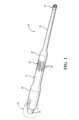
図1,2を参照すると、患者(不図示)に対する医療処置に用いられる本発明による外
科器具10の一実施形態が示されている。図示されるように、外科器具10は、近位端と
遠位端との間に延在する12で総称的に示されるホーン又はシャフトと、近位端における
超音波振動機構14と、遠位端における患者の線維組織除去のための16で総称的に示さ
れる本発明による超音波チップと、を備えている。線維組織の例として、脳の腫瘍部、脊
髄、又は患者の他の重篤な生体構造、例えば、神経外科において除去される腫瘍が挙げら
れる。超音波振動機構14が超音波チップ16に対して超音波振動を生じることを理解さ
れたい。また、このような超音波振動機構の例は、佐藤等に付与された米国特許第6,9
55,680号に開示されていることを理解されたい。この開示内容は、参照することに
よって、その全体がここに含まれるものとする。さらに、外科器具10は、(図示されな
い)ユーザー、例えば、外科医によって操作されることを理解されたい。1 and 2, one embodiment of a
No. 55,680. This disclosure is hereby incorporated by reference in its entirety. Furthermore, it should be understood that
図1~4を参照すると、シャフト12は、略中空円筒であり、略円断面形状を有してい
る。シャフト12は、近位端から遠位端に中心軸に沿って軸方向に延在し、それぞれ、近
位部分18、中間部分20、及び遠位部分22を有している。近位部分18は、中間部分
20の直径よりも大きい直径を有し、中間部分20は、遠位部分22の直径よりも大きい
直径を有している。この実施形態では、遠位部分22は、超音波チップ16に向かってテ
ーパが付されている。シャフト12は、近位端から超音波チップ16に向かって該シャフ
トを軸方向に貫通する通路又は中心管腔24を有している。近位部分18は、超音波振動
機構14に接続するために軸方向に延在する接続部分25を有している。超音波振動機構
14は、シャフト12の近位部分18の接続部分25に接続されることを理解されたい。
また、シャフト12は、超音波チップ16までのシャフトの長さに沿って振幅ゲインをも
たらす幾何学的外部輪郭を有することを理解されたい。さらに、シャフトは、線状であっ
てもよいし、又は円弧状であってもよいことを理解されたい。Referring to FIGS. 1 to 4, the
It should also be appreciated that the
シャフト12は、用途に応じて、チタン合金、ステンレス鋼、等の金属材料、又は複合
材のような非金属材料から作製されている。シャフト12は、一体化された単一片である
。一実施形態では、シャフト12及びチップ16は、一体化された単一片であるとよい。
他の実施形態では、チップ16の遠位端が、(図示されない)ネジのような適切な機構に
よってシャフト12に取り付けられていてもよい。高出力超音波成分に関して金属が当技
術分野において知られていることを理解されたい。また、シャフト12の遠位部分22及
び超音波チップ16は、それぞれ、患者の小切開口内において作用するために比較的小径
、例えば、1cm未満の直径を有することを理解されたい。シャフト12及び超音波チッ
プ16は、用途に応じて、より大きくされてもよいし、又はより小さくされてもよいこと
をさらに理解されたい。The
In other embodiments, the distal end of
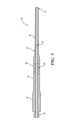
また、外科器具10は、26で総称的に示される振動変換機構をシャフト12の中間部
分20に備えている。振動変換機構26は、超音波振動機構14から伝達された振動を、
シャフト12の中心軸方向の縦振動と遠位部分22の近傍の支点としてシャフト12の中
心軸を有する捻れ振動とから構成される(縦振動―捻れ振動)の合成振動に変換するため
のものである。一実施形態では、振動変換機構26は、シャフト12の中間部分20の周
面に巻かれるように形成された複数の溝28を備えている。振動変換機構26は、シャフ
ト12の他の部分に配置されてもよいし、他の設計を有してもよいことを理解されたい。
This is for converting into a composite vibration (longitudinal vibration - torsional vibration) consisting of longitudinal vibration in the direction of the central axis of the
図5~7を参照すると、超音波チップ16は、接続部分又は移行部分30と、移行部分
30から軸方向に延在するヘッド部分又は接触部分32とを備えている。移行部分30は
、軸方向において半径方向外方にテーパが付されている。移行部分30は、中空であり、
通路24に連通している。ヘッド部分32は、軸方向に延在している。ヘッド部分32は
、略中空であり、円断面形状を有している。ヘッド部分32は、開いており、移行部分3
0及び通路24に連通している。ヘッド部分32は、シャフト12の遠位部分22の端の
直径よりも大きい一定直径を有している。5-7,
It communicates with the
0 and the
また、超音波チップ16は、ヘッド部分32の遠位端に形成された複数の歯34を備え
ている。歯34は、以下に述べる機能を果たすために、ヘッド部分32の壁内に延在する
切込み又は溝36によって、ヘッド部分32の周りに周方向において互いに離間するよう
に形成されている。超音波チップ16のヘッド部分32の外面における溝36の深さは、
内面における溝36の深さよりも大きく、その結果、内面に正のすくい角の切刃をもたら
す傾斜面が生じることになる。
This is greater than the depth of the
この実施形態では、これらの溝36は、いずれも、チップ軸又は長軸37の方向に延在
するように、軸方向に沿って形成されている。ヘッド部分32は、どのような数の歯34
を備えていてもよい。遠位端の幾何学構造を形成する1つの方法として、(図示されない
)回転切断ディスクを用いる方法が挙げられる。幾何学的切断構造は、正のすくい角が外
面と溝36を画定する側面との間に生じるような溝36の軸方向パターンを超音波チップ
16の遠位端に組み入れていることを理解されたい。また、超音波チップ16は、超音波
振動と組合せて線維組織の切除率の著しい向上をもたらす遠位端形状を有していることを
理解されたい。In this embodiment, these
may be provided. One method of forming the distal end geometry is with a rotating cutting disk (not shown). It will be appreciated that the geometric cutting structure incorporates an axial pattern of
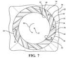
図5~7に示されるように、歯34は、遠位端38,側切刃40,内切刃42、及び遠
位刃44を有している。歯34の遠位端38は、正方形と対照的な略三角形であり、その
結果、外面の鋭利な切断点及び単一内切刃42が生じることになる。遠位切刃44は、正
のすくい角を有している。図示される実施形態では、歯34は、切刃40,42,44の
全てが同一方向かつ同一軸方向パターンにあるように、配置されている。図示される実施
形態では、多数の遠位端38の表面は、平面的であり、又は同一面に配向されている。ま
た、遠位部分32の側面は、垂直面をなしている。溝36は、一直線状の軸方向区域を有
する側切刃40と円弧区域及び逃げ縁45とによって、外面上に画定されている。溝36
は、一直線状の軸方向逃げ縁47と結合する円弧区域を有する内切刃42によって、内面
上に画定されている。逃げ縁45,47間に逃げ面が画定されることを理解されたい。ま
た、遠位切刃44が図7において矢印50によって示されるような捻れ運動を受けた時、
該遠位切刃44は、鈍角で腫瘍と交差し、これによって、正のすくい角をもたらし、切断
が生じることを理解されたい。As shown in FIGS. 5-7, the
is defined on the inner surface by an
It should be appreciated that the
超音波チップ16は、適切なコーティング、例えば、窒化チタン(TiN)又はダイヤ
モンド状コーティング(DLC)によって被覆されるとよい。超音波チップ16は、ヘッ
ド部分32の歯34の遠位端38が捻れ運動又は縦運動と捻れ運動との組合せで振動する
時、最大切除率を達成することを理解されたい。さらに、外科器具10の最大切除率は、
振動が超音波チップ16の正のすくい角の切刃と直交する時に生じることを理解されたい
。
It should be appreciated that vibration occurs when the vibration is perpendicular to the positive rake cutting edge of the
(図示されない)制御コンソールもシステムの一部である。制御コンソールは、駆動信
号を(図示されない)ケーブルを通して外科器具10に供給する。駆動信号は、(図示さ
れない)ドライバに印加される。所定の瞬間に、同一の駆動信号が各ドライバに印加され
る。駆動信号の印加によって、ドライバは、同時に周期的に伸縮する。重ねられた多数の
ドライバは、多くの場合、1cmから5cmの間の長さを有している。ドライバの単一伸
縮サイクル当たりの移動距離、すなわち、振幅は、1μmから10μmの間であるとよい
。シャフト12は、この運動を増幅する。その結果、チタン合金から作製された超音波チ
ップ16の場合、シャフト12の遠位端、従って、該チップ16のヘッド部分32は、完
全な収縮位置から完全な伸張位置に移動する時、典型的には、最大500μm、多くの場
合、350μm未満にわたって移動する。チップ16は、チップステムの長手方向の伸張
/後退がヘド部分32の回転運動も生じさせるようにさらに設計されてもよいことを理解
されたい。また、多くの場合、シャフト12がチップ16の周期的な運動を生じさせるた
めの周期的運動にある時、ヘッド部分32は、振動していると見なされることも理解され
たい。A control console (not shown) is also part of the system. The control console provides drive signals to the
操作時に、超音波チップ16は、超音波振動機構14及び振動変換機構26によって超
音波励起される。超音波チップ16の端における振幅は、最大400μmの範囲内とする
ことができる。中心管腔24を通して、組織を超音波チップ16に当接させるのを促進す
る吸引を行うことができる。超音波チップ16のヘッド部分32の歯34の遠位端38が
、組織に接触する。組織の焼灼(ablation)が、標準的な超音波吸入器に共通の方法(キ
ャビテーション、圧力波、機械的衝撃)によって部分的に生じる。これは、組織が振動す
る表面に最近接した時に生じる。超音波チップ16の振動するヘッド部分32の溝36内
に、高強度超音波場が存在する。図6において、歯34の遠位端38の最適な運動が矢印
A(実線)によって示されており、歯34の底の運動が矢印B(点線)によって示されて
いる。本発明の超音波チップ16の切除機構は、歯34の正のすくい角の切刃に対向する
組織の線維の機械的切除であることを理解されたい。また、歯34の超音波振動する縁が
組織線維に衝撃及び応力を与え、その結果、線維の切除をもたらすことを理解されたい。
さらに、超音波チップ16の切刃40,42,44は、線維組織の効率的な切除を可能に
し、通常の超音波焼灼機構及び制御された吸引との組合せによって、組織の制御された切
除をもたらすことを理解されたい。In operation, the
Furthermore, the cutting edges 40, 42, 44 of the
超音波チップ16の外面における溝36の深さが内面における溝36の深さよりも大き
く、その結果、傾斜面をもたらすことによって、組織がシャフト12の中心管腔24内に
引き込まれたとき、内面の振動する鋭利な刃が該組織を薄切りする。切除された組織の大
きさは、超音波チップ16の内径よりも小さく、その結果、吸引経路の詰まりの可能性が
低減する。超音波振動によって、組織は、超音波チップの周りに巻き付かれず、組織の塊
に望ましくない歪をもたらすことなく、制御された切除が生じることになる。歯34の鋭
利な切刃40,42,44は、清浄な切除を確実なものとし、嵩張る組織の引込みを最小
限に抑えることを理解されたい。When tissue is drawn into the
超音波チップ16の外面における溝36の深さが内面における溝36の深さよりも大き
く、その結果、傾斜面をもたらすことによって、チップ16の両側を通る空気流れが、吸
引がなされた時に低減する。これは、吸引損失を低減させ、組織に対する超音波チップ1
6の良好な当接をもたらすことになる。超音波チップ16の外面における溝36の深さが
内面における溝36の深さよりも大きく、その結果、傾斜面をもたらすことによって、内
切刃42による組織の薄切りの前にチップ16が組織内に押し入る深さを制御することが
できる。この特徴によって、組織の塊への望ましくない応力が最小限に抑えられることを
理解されたい。The depth of the
This results in a good contact of 6. The depth of the
図8~11を参照すると、本発明による外科器具10の他の実施形態が示されている。
外科器具10の部品と同様の部品に100を加えた同様の参照番号が付されている。この
実施形態では、外科器具110は、近位端と遠位端との間に延在するシャフト112と、
近位端における超音波振動機構114と、遠位端における患者の線維組織除去のための超
音波チップ116とを備えている。シャフト112は、近位部分118と、中間部分12
0と、遠位部分122とを備えている。シャフト112は、近位端から超音波チップ11
6に向かって該シャフトを軸方向に貫通する通路124も備えている。また、外科器具1
10は、超音波振動機構114から伝達された振動を変換するための振動変換機構126
をシャフト112の中間部分120に備えていることを理解されたい。8-11, another embodiment of a
Components similar to those of
It includes an
0 and a
A
10 is a
It should be understood that the
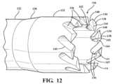
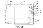
図12~14を参照すると、超音波チップ116は、移行部分130と、移行部分13
0から軸方向に延在するヘッド部分132とを備えている。超音波チップ116は、ヘッ
ド部分132の遠位端に形成された複数の歯134を備えている。歯134は、ヘッド部
分132の壁内に延在する切込み又は溝136によって、ヘッド部分132の周りに周方
向において互いに離間するように形成されている。超音波チップ116の外面における溝
136の深さが内面における溝136の深さよりも大きく、その結果、内面に正のすくい
角の切刃をもたらす傾斜面が生じている。この実施形態では、多数の溝136は、互いに
ずれた角度で形成されている(この場合、外面における切刃は、チップ軸137と平行の
外面に沿って鋭角をなしている)。ヘッド部分132は、どのような数の歯134を備え
ていてもよい。幾何学的切断構造は、正のすくい角が外面と溝136の側面との間に生じ
るような溝136の軸方向パターンを超音波チップ116の遠位端に組み入れていること
を理解されたい。12-14, the
a
図10~12に示されるように、歯134は、遠位端138、側切刃140、内切刃1
42、及び遠位切刃144を有している。遠位端138は、正方形と対照的な略三角形で
あり、その結果、外径の鋭利な切除点及び単一の遠位側内切刃が生じることになる。この
実施形態では、歯134は、切刃140,142,144の方向が異なり、切刃140,
142,144の全てが同一の軸方向パターンにないように、配置されている。図示され
る実施形態では、多数の遠位端138のそれぞれの表面は、互いに異なる平面上に配向さ
れている。図示される実施形態では、遠位部分132の側面は、垂直面をなしておらず、
これによって、効率的な切除及び下側組織の捕捉が確実なものになる。また、遠位切刃1
44が図14に矢印150によって示される捻れ運動を受けたとき、遠位切刃144は、
鈍角で腫瘍と交差し、これによって、正のすくい角をもたらし、切除が行われることを理
解されたい。As shown in FIGS. 10-12, the
42 and a
142, 144 are arranged such that they are not all in the same axial pattern. In the illustrated embodiment, the surfaces of each of the multiple
This ensures efficient ablation and capture of the underlying tissue. In addition, the distal cutting edge 1
When 44 is subjected to a torsional movement shown by
It will be appreciated that it intersects the tumor at an obtuse angle, thereby providing a positive rake angle and resection.
超音波チップ116は、適切な機能コーティング、例えば、窒化チタン(TiN)又は
ダイヤモンド状コーティング(DLC)によって被覆されるとよい。図13において、歯
134の遠位端138の最適な運動が矢印A(実線)よって示され、歯134の底の運動
が矢印B(点線)によって示されている。遠位部分132が捻れ運動又は縦運動と捻れ運
動との組合せで振動する時、最大切除率を達成することを理解されたい。振動の成分が超
音波チップ116の正のすくい角の切刃と直交する時、外科器具110の最大切除率が生
じることをさらに理解されたい。さらに、外科器具110の操作は、外科器具10の操作
と同様であることを理解されたい。
加えて、本発明は、超音波チップ16,116を有する外科器具10,110を操作す
る方法を開示している。この方法は、信号を外科器具10,110に印加し、外科器具1
0,110の超音波チップ16,116を超音波励起させるステップと、超音波チップ1
6,116を患者の外科部位において組織に接触するように移動させるステップと、を含
んでいる。超音波チップ16,116は、遠位端に向かって長軸37,137に沿って軸
方向に延在するヘッド部分32,132を有しており、超音波チップ16,116の遠位
端は、軸37,137に対して正のすくい角を備える切刃44,144を有している。ま
た、本方法は、超音波チップ16,116のヘッド部分32,132の切刃44,144
の正のすくい角に対向する組織の線維を切除することを含んでいる。本方法は、他のステ
ップを含むことを理解されたい。Additionally, the present invention discloses a method of operating a
0,110 ultrasonic chips 16,116, and ultrasonic chip 1
6,116 into contact with tissue at the patient's surgical site. The
involves ablating tissue fibers opposite the positive rake angle of the It should be understood that the method includes other steps.
従って、本発明の外科器具10,110は、正のすくい角の歯34,134を有する超
音波チップ16,116を組み入れている。溝36,136が超音波チップ16,116
の振動の方向と直交する時、より大きい切除を得ることができる。超音波チップ16,1
16の歯34,134の遠位端38,138の表面が互いに異なる面上に配向されている
時、組織に対する接触面及び圧力を低減させることができる。これによって、チップ面と
組織との間の摩擦熱が低下する。超音波チップ16,116の遠位部分32,132の側
面が垂直面をなしていない時、組織に対する接触面積及び圧力の低減を達成することがで
きる。その結果、チップ面と組織との間の摩擦熱が低下することになる。Accordingly, the
A larger ablation can be obtained when the direction of vibration is perpendicular to the direction of vibration.
When the surfaces of the distal ends 38, 138 of the sixteen
本発明の以上の説明は、例示的なものである。用いられた専門用語は、制限のための用
語というよりもむしろ、説明のための用語であることが意図されていることを理解された
い。本発明の多くの修正及び変更が、前述の示唆に照らして可能である。それ故、本発明
は、具体的に記載されている方法以外の方法によって実施されてもよい。The above description of the invention is exemplary. It is to be understood that the terminology used is intended to be terms of description rather than terms of limitation. Many modifications and variations of the invention are possible in light of the above teachings. Therefore, the invention may be practiced otherwise than as specifically described.
Claims (6)
Translated fromJapanese近位端と遠位端との間に軸方向に延在し、組織に吸引を適用するように構成された中心管腔を画定し、かつ、捻れ振動と縦振動の合成振動を生成するように構成された振動変換機構を含むシャフト、および、
前記シャフトの長軸に沿って軸方向に遠位端まで延在するヘッド部分であって、前記中心管腔を画成する内周面、前記内周面の反対側の外周面、前記遠位端から前記内周面と前記外周面との間に延在する複数の溝、および、前記溝によって周方向に離間するように形成された複数の歯を備え、前記捻れ振動と縦振動の合成振動によって第1の方向、および、前記第1の方向と反対の第2の方向に移動させられるヘッド部分を備え、
前記歯の各々は、前記外周面と前記遠位端の間に画定される外縁、前記遠位端において前記内周面と前記外周面との間に延在する遠位切刃、および、前記外周面と前記溝のうち1つの溝の側面との間に画定される側切刃を備え、かつ、前記遠位切刃と、前記側切刃と、前記溝の円弧部分との間に画定される三角形状部分を含み、前記外縁、前記遠位切刃、および前記側切刃の交点は前記遠位端における鋭利な切断点を画定し、前記遠位端は、前記内周面から前記外周面に向かって外方向にテーパが付されて、前記三角形状部分と前記遠位端が前記歯を前記組織に押し込むように構成され、かつ、前記遠位切刃および前記側切刃は前記ヘッド部分が前記第1の方向に移動すると前記組織を薄切りし、前記ヘッド部分が前記第2の方向に移動すると前記組織を引くように構成される、超音波外科器具。An ultrasonic surgical instrument configured for combined vibration of torsional vibration and longitudinal vibration,
a central lumen extending axially between the proximal and distal ends and configured to apply suction to the tissue and to generate a composite vibration of torsional and longitudinal vibrations; a shaft including a vibration conversion mechanism configured to;
a head portion extending axially along the longitudinal axis of the shaft to a distal end, the head portion comprising: an inner circumferential surface defining the central lumen; an outer circumferential surface opposite the inner circumferential surface; a plurality of grooves extending from an end between the inner circumferential surface and the outer circumferential surface, and a plurality of teeth formed to be spaced apart in the circumferential direction by the grooves, and a combination of the torsional vibration and longitudinal vibration. a head portion that is moved by vibration in a first direction and a second direction opposite to the first direction;
Each of the teeth includes an outer edge defined between the outer circumferential surface and the distal end, a distal cutting edge extending between the inner circumferential surface and the outer circumferential surface at the distal end, and a side cutting edge defined between an outer circumferential surface and a side surface of one of the grooves, and defined between the distal cutting edge, the side cutting edge, and an arcuate portion of the groove; the intersectionof the outer edge , the distal cutting edge, and the side cutting edge defines a sharp cutting pointat the distal end; tapering outwardly toward a peripheral surface, the triangular portion and the distal end are configured to force the tooth into the tissue, and the distal cutting edge and the side cutting edge are configured to An ultrasonic surgical instrument configured to slice the tissue when the head portion moves in the first direction and pull the tissue when the head portion moves in the second direction.
近位端と遠位端との間に軸方向に延在し、組織に吸引を適用するように構成された中心管腔を画定し、かつ、捻れ振動と縦振動の合成振動を生成するように構成された振動変換機構を含むシャフト、および、
前記シャフトの長軸に沿って軸方向に遠位端まで延在するヘッド部分であって、前記中心管腔を画成する内周面、前記内周面の反対側の外周面、前記遠位端から前記内周面と前記外周面との間に延在する複数の溝、および、前記溝によって周方向に離間するように形成された複数の歯を備え、前記捻れ振動と縦振動の合成振動によって第1の方向、および、前記第1の方向と反対の第2の方向に移動させられるヘッド部分を備え、
前記歯の各々は、前記遠位端において前記内周面と前記外周面との間に延在する遠位切刃、および、前記外周面と前記溝のうち1つの溝の側面との間に画定される側切刃を備え、前記溝は、前記内周面とともに内切刃を形成する傾斜面によって画定され、前記内切刃は、前記ヘッド部分の前記第1の方向への移動により正のすくい角で前記組織と交差するように構成され、かつ、前記遠位切刃および前記側切刃は前記ヘッド部分が前記第1の方向に移動すると前記組織を薄切りし、前記ヘッド部分が前記第2の方向に移動すると前記組織を引くように構成される、超音波外科器具。An ultrasonic surgical instrument configured for combined vibration of torsional vibration and longitudinal vibration,
a central lumen extending axially between the proximal and distal ends and configured to apply suction to the tissue and to generate a composite vibration of torsional and longitudinal vibrations; a shaft including a vibration conversion mechanism configured to;
a head portion extending axially along the longitudinal axis of the shaft to a distal end, the head portion comprising: an inner circumferential surface defining the central lumen; an outer circumferential surface opposite the inner circumferential surface; a plurality of grooves extending from an end between the inner circumferential surface and the outer circumferential surface, and a plurality of teeth formed to be spaced apart in the circumferential direction by the grooves, and a combination of the torsional vibration and longitudinal vibration. a head portion that is moved by vibration in a first direction and a second direction opposite to the first direction;
Each of the teeth includes a distal cutting edge extending at the distal end between the inner circumferential surface and the outer circumferential surface, and a distal cutting edge extending between the outer circumferential surface and a side surface of one of the grooves.a side cutting edge defined, the groove being defined by an inclined surface forming an inner cutting edge with the inner circumferential surface, the inner cutting edge being straightened by movement of the head portion in the first direction; the distal cutting edge and the side cutting edge are configured to intersect the tissue at a rake angle of, and the distal cutting edge and the side cutting edge slice the tissue as the head portion moves in the first direction; An ultrasonic surgical instrument configured to pull the tissue when moved in a second direction.
近位端と遠位端との間に軸方向に延在し、組織に吸引を適用するように構成された中心管腔を画定し、かつ、捻れ振動と縦振動の合成振動を生成するように構成された振動変換機構を含むシャフト、および、
前記シャフトの長軸に沿って軸方向に遠位端まで延在するヘッド部分であって、前記中心管腔を画成する内周面、前記内周面の反対側の外周面、前記遠位端から前記内周面と前記外周面との間に延在する複数の溝、および、前記溝によって周方向に離間するように形成された複数の歯を備え、前記捻れ振動と縦振動の合成振動によって第1の方向、および、前記第1の方向と反対の第2の方向に移動させられるヘッド部分を備え、
前記歯の各々は、前記遠位端において前記内周面と前記外周面との間に延在する遠位切刃、および、前記外周面と前記溝のうち1つの溝の側面との間に画定される側切刃を備え、前記外周面における前記溝の深さは前記内周面における前記溝の深さよりも大きく、前記遠位切刃と前記側切刃による前記組織の切除中に前記組織に対する前記ヘッド部分の吸引による当接を維持するための傾斜面が画成され、前記傾斜面は、前記中心管腔よりも小さいサイズに前記組織を薄切りするように構成される内切刃を前記内周面とともに形成しており、前記遠位切刃および前記側切刃は、前記ヘッド部分が前記第1の方向に移動すると前記組織を薄切りし、前記ヘッド部分が前記第2の方向に移動すると前記組織を引くように構成される、超音波外科器具。An ultrasonic surgical instrument configured for combined vibration of torsional vibration and longitudinal vibration,
a central lumen extending axially between the proximal and distal ends and configured to apply suction to the tissue and to generate a composite vibration of torsional and longitudinal vibrations; a shaft including a vibration conversion mechanism configured to;
a head portion extending axially along the longitudinal axis of the shaft to a distal end, the head portion comprising: an inner circumferential surface defining the central lumen; an outer circumferential surface opposite the inner circumferential surface; a plurality of grooves extending from an end between the inner circumferential surface and the outer circumferential surface, and a plurality of teeth formed to be spaced apart in the circumferential direction by the grooves, and a combination of the torsional vibration and longitudinal vibration. a head portion that is moved by vibration in a first direction and a second direction opposite to the first direction;
Each of the teeth includes a distal cutting edge extending at the distal end between the inner circumferential surface and the outer circumferential surface, and a distal cutting edge extending between the outer circumferential surface and a side surface of one of the grooves. a side cutting edge defined therein, the depth of the groove at the outer circumferential surface being greater than the depth of the groove at the inner circumferential surface; An angled surface is defined formaintaining suction abutment of the head portion against tissue, the angled surface having an internal cutting blade configured to slice the tissue to a size smaller than the central lumen. The distal cutting edge and the side cutting edgeare formed with the inner circumferential surface, and the distal cutting edge and the side cutting edge slice the tissue when the head portion moves in the first direction, and when the head portion moves in the second direction. An ultrasonic surgical instrument configured to pull the tissue as it moves.
Priority Applications (1)
| Application Number | Priority Date | Filing Date | Title |
|---|---|---|---|
| JP2023104336AJP7592792B2 (en) | 2015-06-17 | 2023-06-26 | Surgical instrument with ultrasonic tip for fibrous tissue removal - Patents.com |
Applications Claiming Priority (3)
| Application Number | Priority Date | Filing Date | Title |
|---|---|---|---|
| US201562180656P | 2015-06-17 | 2015-06-17 | |
| US62/180,656 | 2015-06-17 | ||
| JP2017565085AJP6924704B2 (en) | 2015-06-17 | 2016-06-15 | Surgical instrument with ultrasonic tip for fibrous tissue removal |
Related Parent Applications (1)
| Application Number | Title | Priority Date | Filing Date |
|---|---|---|---|
| JP2017565085ADivisionJP6924704B2 (en) | 2015-06-17 | 2016-06-15 | Surgical instrument with ultrasonic tip for fibrous tissue removal |
Related Child Applications (1)
| Application Number | Title | Priority Date | Filing Date |
|---|---|---|---|
| JP2023104336ADivisionJP7592792B2 (en) | 2015-06-17 | 2023-06-26 | Surgical instrument with ultrasonic tip for fibrous tissue removal - Patents.com |
Publications (2)
| Publication Number | Publication Date |
|---|---|
| JP2021184807A JP2021184807A (en) | 2021-12-09 |
| JP7348239B2true JP7348239B2 (en) | 2023-09-20 |
Family
ID=56497828
Family Applications (3)
| Application Number | Title | Priority Date | Filing Date |
|---|---|---|---|
| JP2017565085AActiveJP6924704B2 (en) | 2015-06-17 | 2016-06-15 | Surgical instrument with ultrasonic tip for fibrous tissue removal |
| JP2021126504AActiveJP7348239B2 (en) | 2015-06-17 | 2021-08-02 | Surgical instrument with ultrasound tip for fibrous tissue removal |
| JP2023104336AActiveJP7592792B2 (en) | 2015-06-17 | 2023-06-26 | Surgical instrument with ultrasonic tip for fibrous tissue removal - Patents.com |
Family Applications Before (1)
| Application Number | Title | Priority Date | Filing Date |
|---|---|---|---|
| JP2017565085AActiveJP6924704B2 (en) | 2015-06-17 | 2016-06-15 | Surgical instrument with ultrasonic tip for fibrous tissue removal |
Family Applications After (1)
| Application Number | Title | Priority Date | Filing Date |
|---|---|---|---|
| JP2023104336AActiveJP7592792B2 (en) | 2015-06-17 | 2023-06-26 | Surgical instrument with ultrasonic tip for fibrous tissue removal - Patents.com |
Country Status (7)
| Country | Link |
|---|---|
| US (2) | US11109880B2 (en) |
| EP (3) | EP4215135B8 (en) |
| JP (3) | JP6924704B2 (en) |
| CN (2) | CN108024822B (en) |
| AU (2) | AU2016280071B2 (en) |
| CA (1) | CA2989824C (en) |
| WO (1) | WO2016205335A1 (en) |
Families Citing this family (16)
| Publication number | Priority date | Publication date | Assignee | Title |
|---|---|---|---|---|
| US10076349B2 (en)* | 2013-03-15 | 2018-09-18 | Misonix, Inc. | Ultrasonic surgical drill and associated surgical method |
| EP4215135B8 (en) | 2015-06-17 | 2025-01-01 | Stryker European Operations Holdings LLC | Surgical instrument with ultrasonic tip for fibrous tissue removal |
| WO2019008782A1 (en) | 2017-07-05 | 2019-01-10 | オリンパス株式会社 | Ultrasonic probe, ultrasonic treatment tool, and ultrasonic treatment assembly |
| JP6843994B2 (en)* | 2017-07-05 | 2021-03-17 | オリンパス株式会社 | Ultrasound probe and ultrasound treatment assembly |
| JP6801103B2 (en)* | 2017-07-05 | 2020-12-16 | オリンパス株式会社 | Ultrasound probe and ultrasound treatment assembly |
| CN110868946B (en)* | 2017-07-05 | 2022-07-29 | 奥林巴斯株式会社 | Ultrasonic probe and ultrasonic treatment unit |
| US20190150703A1 (en)* | 2017-11-17 | 2019-05-23 | Gyrus Acmi, Inc. | Coated endoscopy probe |
| CN109893209B (en)* | 2017-11-17 | 2022-11-15 | 吉鲁斯·阿克米有限责任公司 | Coated endoscopic probe |
| CN108420499A (en)* | 2018-02-02 | 2018-08-21 | 李东峰 | A kind of self-tapping type skull core drill and its application method |
| USD911530S1 (en)* | 2018-09-24 | 2021-02-23 | Stryker European Holdings I, Llc | Sleeve for ultrasonic handpiece |
| AU2019347721B2 (en) | 2018-09-24 | 2025-07-10 | Stryker European Operations Holdings Llc | Ultrasonic tip with protrusion defining a preaspiration hole |
| GB2578089B (en)* | 2018-09-25 | 2022-10-05 | Radley Scient Limited | Orthopaedic cement removal tools and method |
| USD974558S1 (en) | 2020-12-18 | 2023-01-03 | Stryker European Operations Limited | Ultrasonic knife |
| CN114886513A (en)* | 2022-05-11 | 2022-08-12 | 北京水木天蓬医疗设备有限公司 | Medical ultrasonic knife, medical ultrasonic knife system and robot-assisted ultrasonic knife system |
| CN115500900B (en)* | 2022-09-13 | 2024-03-19 | 以诺康医疗科技(苏州)有限公司 | Cutting part, transition part and ultrasonic surgical knife for ultrasonic surgical knife |
| EP4616814A1 (en)* | 2022-11-11 | 2025-09-17 | SMTP Medical Co., Ltd. | Medical ultrasonic scalpel, medical ultrasonic scalpel system, and robot-assisted ultrasonic scalpel system |
Citations (4)
| Publication number | Priority date | Publication date | Assignee | Title |
|---|---|---|---|---|
| JP2001191295A (en) | 2000-01-07 | 2001-07-17 | Kichiji Matsuda | Cutter for punching |
| JP2008119250A (en) | 2006-11-13 | 2008-05-29 | Miwatec:Kk | Ultrasonic surgical handpiece and horn |
| JP2009131634A (en) | 2007-11-30 | 2009-06-18 | Young Gi Kim | Reamer for operating implant |
| JP2010504138A (en) | 2006-09-25 | 2010-02-12 | ピエゾサージェリー ソシエタ レスポンサビリタ リミタータ | Handpiece with surgical tool for drilling holes in bone tissue |
Family Cites Families (95)
| Publication number | Priority date | Publication date | Assignee | Title |
|---|---|---|---|---|
| US473231A (en)* | 1892-04-19 | Plug-cutter | ||
| US3609056A (en)* | 1969-06-05 | 1971-09-28 | Everett D Hougen | Hole cutter |
| BE788401A (en) | 1971-12-29 | 1973-03-05 | Hougen Everett D | ROTARY CUTTING TOOL |
| DE2242863A1 (en) | 1972-08-31 | 1974-03-14 | Karl Storz | SURGICAL ELEMENT FOR CRUSHING STONES IN THE HUMAN BODY BY ULTRASOUND |
| GB1457544A (en)* | 1973-11-28 | 1976-12-01 | Mo I Vysshee Tekhn Uchilische | Surgical instrument for ultrasonic separation of biological tissue |
| US4063557A (en) | 1976-04-01 | 1977-12-20 | Cavitron Corporation | Ultrasonic aspirator |
| US4265621A (en) | 1979-10-19 | 1981-05-05 | Mcvey Kenneth E | Tip for dental aspirator |
| JPS56172073U (en)* | 1980-05-21 | 1981-12-18 | ||
| SU936897A1 (en) | 1980-08-13 | 1982-06-23 | 1-Я Городская Легочно-Хирургическая Туберкулезная Больница Г.Новосибирска | Method of surgical treating of polycavernous pulmonary tuberculosis |
| US4452554A (en)* | 1981-09-21 | 1984-06-05 | Hougen Everett D | Annular hole cutter |
| GR77678B (en)* | 1981-09-21 | 1984-09-25 | Hougen Everett D | |
| JPS5880116U (en)* | 1981-11-20 | 1983-05-31 | 株式会社日立製作所 | Trepankatsuta |
| GB2160129B (en) | 1984-06-11 | 1987-09-16 | Omi Kogyo Kk | Hole cutter |
| US4750902A (en) | 1985-08-28 | 1988-06-14 | Sonomed Technology, Inc. | Endoscopic ultrasonic aspirators |
| US4823793A (en) | 1985-10-30 | 1989-04-25 | The United States Of America As Represented By The Administrator Of The National Aeronuautics & Space Administration | Cutting head for ultrasonic lithotripsy |
| US4827911A (en) | 1986-04-02 | 1989-05-09 | Cooper Lasersonics, Inc. | Method and apparatus for ultrasonic surgical fragmentation and removal of tissue |
| USD313074S (en) | 1987-07-29 | 1990-12-18 | Aloka Co., Ltd. | Ultrasonic aspirator for microscope neurosurgery |
| US4931047A (en) | 1987-09-30 | 1990-06-05 | Cavitron, Inc. | Method and apparatus for providing enhanced tissue fragmentation and/or hemostasis |
| US5015227A (en) | 1987-09-30 | 1991-05-14 | Valleylab Inc. | Apparatus for providing enhanced tissue fragmentation and/or hemostasis |
| US4949718B1 (en) | 1988-09-09 | 1998-11-10 | Gynelab Products | Intrauterine cauterizing apparatus |
| US5911699A (en) | 1990-07-17 | 1999-06-15 | Aziz Yehia Anis | Removal of tissue |
| US5221282A (en) | 1991-05-29 | 1993-06-22 | Sonokinetics Group | Tapered tip ultrasonic aspirator |
| USD339419S (en) | 1991-06-11 | 1993-09-14 | Advanced Osseous Technologies, Inc. | Ultrasonic gouge |
| IT1256668B (en) | 1992-01-24 | 1995-12-12 | Apparatus and method for treatment of tissues, especially adipose tissues | |
| US5456689A (en) | 1993-10-13 | 1995-10-10 | Arnold J. Kresch | Method and device for tissue resection |
| US5366468A (en)* | 1993-11-09 | 1994-11-22 | Linvatec Corporation | Double bladed surgical router having aspiration ports within flutes |
| US6705323B1 (en) | 1995-06-07 | 2004-03-16 | Conceptus, Inc. | Contraceptive transcervical fallopian tube occlusion devices and methods |
| US5695513A (en) | 1996-03-01 | 1997-12-09 | Metagen, Llc | Flexible cutting tool and methods for its use |
| JP3867867B2 (en) | 1996-07-30 | 2007-01-17 | 東京瓦斯株式会社 | Resin tube cutter |
| US5830192A (en) | 1996-12-09 | 1998-11-03 | Staar Surgical Company, Inc. | Irrigation sleeve for phacoemulsification apparatus |
| US6007499A (en) | 1997-10-31 | 1999-12-28 | University Of Washington | Method and apparatus for medical procedures using high-intensity focused ultrasound |
| US6508816B2 (en) | 1998-03-27 | 2003-01-21 | John H. Shadduck | Medical instrument working end creating very high pressure gradients |
| US6162235A (en) | 1998-05-18 | 2000-12-19 | Ethicon Endo-Surgery, Inc. | Method of tissue morcellation using an ultrasonic surgical instrument with a ballistic specimen bag |
| US6371986B1 (en) | 1998-10-27 | 2002-04-16 | George W. Bagby | Spinal fusion device, bone joining implant, and vertebral fusion implant |
| US6254601B1 (en) | 1998-12-08 | 2001-07-03 | Hysterx, Inc. | Methods for occlusion of the uterine arteries |
| US6695781B2 (en) | 1999-10-05 | 2004-02-24 | Omnisonics Medical Technologies, Inc. | Ultrasonic medical device for tissue remodeling |
| US6626855B1 (en) | 1999-11-26 | 2003-09-30 | Therus Corpoation | Controlled high efficiency lesion formation using high intensity ultrasound |
| AU5943900A (en)* | 1999-11-29 | 2001-05-31 | Alcon Universal Limited | Torsional ultrasound handpiece |
| US7223279B2 (en) | 2000-04-21 | 2007-05-29 | Vascular Control Systems, Inc. | Methods for minimally-invasive, non-permanent occlusion of a uterine artery |
| US6641395B2 (en)* | 2000-08-02 | 2003-11-04 | Nobel Biocare Ab | Endosseous implant drill |
| US6840935B2 (en) | 2000-08-09 | 2005-01-11 | Bekl Corporation | Gynecological ablation procedure and system using an ablation needle |
| US6503263B2 (en) | 2000-09-24 | 2003-01-07 | Medtronic, Inc. | Surgical micro-shaving instrument with elevator tip |
| JP2002143177A (en) | 2000-11-07 | 2002-05-21 | Miwatec:Kk | Ultrasonic handpiece and ultrasonic horn used for it |
| US6588992B2 (en) | 2001-02-06 | 2003-07-08 | Black & Decker Inc. | Hole saw |
| US6723110B2 (en) | 2001-04-19 | 2004-04-20 | Synergetics, Inc. | High efficiency ultrasonic surgical aspiration tip |
| US6916328B2 (en) | 2001-11-15 | 2005-07-12 | Expanding Concepts, L.L.C | Percutaneous cellulite removal system |
| JP2003190180A (en) | 2001-12-27 | 2003-07-08 | Miwatec:Kk | Composite vibration ultrasonic handpiece |
| US6902558B2 (en) | 2002-03-11 | 2005-06-07 | Microsurgical Technology, Inc. | Aspirator tip |
| USD478383S1 (en) | 2002-04-17 | 2003-08-12 | Synergetics, Inc. | Ultrasonic surgical aspiration tip |
| US20030204199A1 (en)* | 2002-04-30 | 2003-10-30 | Novak Theodore A. D. | Device and method for ultrasonic tissue excision with tissue selectivity |
| US20040243136A1 (en)* | 2003-05-30 | 2004-12-02 | Parag Gupta | Dual cut surgical saw blade |
| US20050105981A1 (en)* | 2003-09-26 | 2005-05-19 | The M. K. Morse Company | Hole cutter and method for producing |
| USD511002S1 (en) | 2004-02-09 | 2005-10-25 | Synergetics, Inc. | Torsional dissection tip |
| US7658136B2 (en) | 2004-12-22 | 2010-02-09 | Black & Decker Inc. | Hole saw blade |
| US20120165848A1 (en) | 2010-08-02 | 2012-06-28 | Guided Therapy Systems, Llc | System and method for treating cartilage |
| GB0426503D0 (en)* | 2004-12-02 | 2005-01-05 | Orthosonics Ltd | Improved osteotome |
| US7918795B2 (en) | 2005-02-02 | 2011-04-05 | Gynesonics, Inc. | Method and device for uterine fibroid treatment |
| US20060178698A1 (en) | 2005-02-08 | 2006-08-10 | Mcintyre Jon T | Method and device for canulation and occlusion of uterine arteries |
| US20060184190A1 (en) | 2005-02-14 | 2006-08-17 | Feiler Ernest M | Trans-myocardial fluid-jet revascularization arrangement |
| US20060190003A1 (en) | 2005-02-18 | 2006-08-24 | Alcon, Inc. | Surgical method |
| US8142460B2 (en) | 2005-04-15 | 2012-03-27 | Integra Lifesciences (Ireland) Ltd. | Bone abrading ultrasonic horns |
| US8092475B2 (en) | 2005-04-15 | 2012-01-10 | Integra Lifesciences (Ireland) Ltd. | Ultrasonic horn for removal of hard tissue |
| EP1895915B1 (en) | 2005-06-06 | 2016-03-23 | AMS Research Corporation | Devices for ligating uterine arteries |
| US8512333B2 (en) | 2005-07-01 | 2013-08-20 | Halt Medical Inc. | Anchored RF ablation device for the destruction of tissue masses |
| US7967763B2 (en) | 2005-09-07 | 2011-06-28 | Cabochon Aesthetics, Inc. | Method for treating subcutaneous tissues |
| US20070093791A1 (en)* | 2005-09-19 | 2007-04-26 | Inion Ltd. | Device for removal of fastening means from human tissue |
| US7556459B2 (en) | 2005-11-07 | 2009-07-07 | Black & Decker Inc. | Hole saw having a drill bit with a pilot tip |
| WO2007085682A1 (en)* | 2006-01-26 | 2007-08-02 | Nokia Corporation | Eye tracker device |
| EP2012673A4 (en) | 2006-04-20 | 2011-05-18 | Univ California | THERMAL TREATMENT METHOD FOR MYOLYSIS AND DESTRUCTION OF BENIGN UTERINE TUMORS |
| US8430897B2 (en) | 2006-08-29 | 2013-04-30 | Misonix Incorporated | Ultrasonic wound debrider probe and method of use |
| US7763033B2 (en) | 2006-10-18 | 2010-07-27 | Interlace Medical, Inc. | System and methods for preventing intravasation during intrauterine procedures |
| US20080228180A1 (en) | 2007-03-13 | 2008-09-18 | Halt Medical, Inc | Ablation system and heat preventing electrodes therefor |
| CN101674780B (en)* | 2007-03-22 | 2012-05-23 | 伊西康内外科公司 | Ultrasonic surgical instrument blades |
| US7740088B1 (en) | 2007-10-30 | 2010-06-22 | The United States Of America As Represented By The Administrator Of The National Aeronautics And Space Administration | Ultrasonic rotary-hammer drill |
| US8251991B2 (en) | 2007-11-14 | 2012-08-28 | Halt Medical Inc. | Anchored RF ablation device for the destruction of tissue masses |
| US8241276B2 (en) | 2007-11-14 | 2012-08-14 | Halt Medical Inc. | RF ablation device with jam-preventing electrical coupling member |
| BRPI0801330A2 (en) | 2008-01-03 | 2009-08-25 | Halt Medical Inc | RF-anchored ablation device for tissue mass destruction |
| CA2720761A1 (en) | 2008-04-10 | 2009-10-15 | Atheromed, Inc. | Atherectomy devices and methods |
| JP2009261667A (en)* | 2008-04-25 | 2009-11-12 | Miwatec:Kk | Ultrasonic horn and ultrasonic handpiece |
| US8118823B2 (en)* | 2008-06-12 | 2012-02-21 | Integra Lifesciences (Ireland) Ltd. | Shear stress ultrasonic horn for ultrasonic surgical aspiration |
| DK2233085T3 (en)* | 2009-03-23 | 2012-08-27 | Mectron S P A | Surgical instrument for bone cutting |
| WO2010151619A2 (en) | 2009-06-24 | 2010-12-29 | Optogen Medical Llc | Devices, systems and methods for treatment of soft tissue |
| US8531064B2 (en) | 2010-02-11 | 2013-09-10 | Ethicon Endo-Surgery, Inc. | Ultrasonically powered surgical instruments with rotating cutting implement |
| CN101817102B (en)* | 2010-03-30 | 2012-07-04 | 浙江欣兴工具有限公司 | Annular drilling tool |
| US8668032B2 (en) | 2011-01-25 | 2014-03-11 | Christopher Dale Langhart | Core drill bit |
| US20120245575A1 (en) | 2011-03-23 | 2012-09-27 | Halt Medical Inc. | User interface and navigational tool for remote control of an anchored rf ablation device for destruction of tissue masses |
| WO2013056262A1 (en) | 2011-10-13 | 2013-04-18 | Atheromed, Inc. | Atherectomy apparatus, systems and methods |
| WO2013059263A1 (en) | 2011-10-17 | 2013-04-25 | Sound Surgical Technologies, Llc | Ultrasonic probe for treating cellulite |
| DE102011084792A1 (en)* | 2011-10-19 | 2013-04-25 | Söring GmbH | sonotrode |
| DE102012200666B4 (en) | 2012-01-18 | 2014-09-11 | Söring GmbH | Sonotrode, surgical instrument with a sonotrode and production method for a sonotrode |
| AU2013345341B2 (en)* | 2012-11-19 | 2017-12-07 | Huwais IP Holding LLC | Autografting osteotome |
| US9918736B2 (en)* | 2013-09-25 | 2018-03-20 | Covidien Lp | Ultrasonic dissector and sealer |
| US9649125B2 (en)* | 2013-10-15 | 2017-05-16 | Hermes Innovations Llc | Laparoscopic device |
| US9636132B2 (en) | 2014-09-08 | 2017-05-02 | Medtronic Xomed, Inc. | Tumor debulker |
| EP4215135B8 (en) | 2015-06-17 | 2025-01-01 | Stryker European Operations Holdings LLC | Surgical instrument with ultrasonic tip for fibrous tissue removal |
- 2016
- 2016-06-15EPEP23162590.6Apatent/EP4215135B8/enactiveActive
- 2016-06-15WOPCT/US2016/037582patent/WO2016205335A1/ennot_activeCeased
- 2016-06-15CACA2989824Apatent/CA2989824C/enactiveActive
- 2016-06-15CNCN201680041963.3Apatent/CN108024822B/enactiveActive
- 2016-06-15EPEP16741409.3Apatent/EP3310276B1/enactiveActive
- 2016-06-15CNCN202110613100.1Apatent/CN113331915B/enactiveActive
- 2016-06-15EPEP19202480.0Apatent/EP3613369B1/enactiveActive
- 2016-06-15AUAU2016280071Apatent/AU2016280071B2/enactiveActive
- 2016-06-15JPJP2017565085Apatent/JP6924704B2/enactiveActive
- 2017
- 2017-12-15USUS15/843,740patent/US11109880B2/enactiveActive
- 2021
- 2021-05-24USUS17/328,102patent/US12082840B2/enactiveActive
- 2021-06-30AUAU2021204590Apatent/AU2021204590B2/enactiveActive
- 2021-08-02JPJP2021126504Apatent/JP7348239B2/enactiveActive
- 2023
- 2023-06-26JPJP2023104336Apatent/JP7592792B2/enactiveActive
Patent Citations (4)
| Publication number | Priority date | Publication date | Assignee | Title |
|---|---|---|---|---|
| JP2001191295A (en) | 2000-01-07 | 2001-07-17 | Kichiji Matsuda | Cutter for punching |
| JP2010504138A (en) | 2006-09-25 | 2010-02-12 | ピエゾサージェリー ソシエタ レスポンサビリタ リミタータ | Handpiece with surgical tool for drilling holes in bone tissue |
| JP2008119250A (en) | 2006-11-13 | 2008-05-29 | Miwatec:Kk | Ultrasonic surgical handpiece and horn |
| JP2009131634A (en) | 2007-11-30 | 2009-06-18 | Young Gi Kim | Reamer for operating implant |
Also Published As
| Publication number | Publication date |
|---|---|
| JP2018518282A (en) | 2018-07-12 |
| AU2021204590B2 (en) | 2023-09-14 |
| JP7592792B2 (en) | 2024-12-02 |
| US12082840B2 (en) | 2024-09-10 |
| EP4215135A1 (en) | 2023-07-26 |
| WO2016205335A1 (en) | 2016-12-22 |
| US20180103976A1 (en) | 2018-04-19 |
| EP3310276B1 (en) | 2019-10-16 |
| EP3310276A1 (en) | 2018-04-25 |
| CN108024822A (en) | 2018-05-11 |
| EP4215135B1 (en) | 2024-11-27 |
| CN108024822B (en) | 2021-07-02 |
| AU2016280071A1 (en) | 2018-01-18 |
| EP4215135B8 (en) | 2025-01-01 |
| EP3613369B1 (en) | 2023-03-22 |
| AU2016280071B2 (en) | 2021-04-01 |
| CN113331915A (en) | 2021-09-03 |
| CN113331915B (en) | 2024-09-10 |
| CA2989824C (en) | 2023-10-17 |
| US11109880B2 (en) | 2021-09-07 |
| EP3613369A1 (en) | 2020-02-26 |
| JP2021184807A (en) | 2021-12-09 |
| AU2021204590A1 (en) | 2021-07-29 |
| CA2989824A1 (en) | 2016-12-22 |
| JP6924704B2 (en) | 2021-08-25 |
| JP2023134513A (en) | 2023-09-27 |
| US20210275208A1 (en) | 2021-09-09 |
Similar Documents
| Publication | Publication Date | Title |
|---|---|---|
| JP7348239B2 (en) | Surgical instrument with ultrasound tip for fibrous tissue removal | |
| US11272949B2 (en) | Ultrasonic surgical drill and associated surgical method | |
| US8142460B2 (en) | Bone abrading ultrasonic horns | |
| US8092475B2 (en) | Ultrasonic horn for removal of hard tissue | |
| CN100420424C (en) | Ultrasonic scalpels and instruments with gain steps | |
| JP6567738B2 (en) | Ultrasonic instrument assembly and manufacturing method thereof | |
| US6723110B2 (en) | High efficiency ultrasonic surgical aspiration tip | |
| US20170209152A1 (en) | Surgical saw blade | |
| EP3322355B1 (en) | Ultrasonic wound treatment apparatus | |
| EP2119403A1 (en) | Osteotomes for ultrasonic bone surgery, particularly maxillofacial, dental and orthopedic surgery | |
| JPH0529697Y2 (en) |
Legal Events
| Date | Code | Title | Description |
|---|---|---|---|
| A521 | Request for written amendment filed | Free format text:JAPANESE INTERMEDIATE CODE: A523 Effective date:20210901 | |
| A621 | Written request for application examination | Free format text:JAPANESE INTERMEDIATE CODE: A621 Effective date:20210901 | |
| A977 | Report on retrieval | Free format text:JAPANESE INTERMEDIATE CODE: A971007 Effective date:20220818 | |
| A131 | Notification of reasons for refusal | Free format text:JAPANESE INTERMEDIATE CODE: A131 Effective date:20220823 | |
| A601 | Written request for extension of time | Free format text:JAPANESE INTERMEDIATE CODE: A601 Effective date:20221124 | |
| A521 | Request for written amendment filed | Free format text:JAPANESE INTERMEDIATE CODE: A523 Effective date:20230120 | |
| A02 | Decision of refusal | Free format text:JAPANESE INTERMEDIATE CODE: A02 Effective date:20230224 | |
| A521 | Request for written amendment filed | Free format text:JAPANESE INTERMEDIATE CODE: A523 Effective date:20230626 | |
| A911 | Transfer to examiner for re-examination before appeal (zenchi) | Free format text:JAPANESE INTERMEDIATE CODE: A911 Effective date:20230720 | |
| TRDD | Decision of grant or rejection written | ||
| A01 | Written decision to grant a patent or to grant a registration (utility model) | Free format text:JAPANESE INTERMEDIATE CODE: A01 Effective date:20230815 | |
| A61 | First payment of annual fees (during grant procedure) | Free format text:JAPANESE INTERMEDIATE CODE: A61 Effective date:20230907 | |
| R150 | Certificate of patent or registration of utility model | Ref document number:7348239 Country of ref document:JP Free format text:JAPANESE INTERMEDIATE CODE: R150 |