JP7348199B2 - Device for atrial appendage exclusion - Google Patents
Device for atrial appendage exclusionDownload PDFInfo
- Publication number
- JP7348199B2 JP7348199B2JP2020551904AJP2020551904AJP7348199B2JP 7348199 B2JP7348199 B2JP 7348199B2JP 2020551904 AJP2020551904 AJP 2020551904AJP 2020551904 AJP2020551904 AJP 2020551904AJP 7348199 B2JP7348199 B2JP 7348199B2
- Authority
- JP
- Japan
- Prior art keywords
- trigger
- actuated
- release button
- movement
- applicator
- Prior art date
- Legal status (The legal status is an assumption and is not a legal conclusion. Google has not performed a legal analysis and makes no representation as to the accuracy of the status listed.)
- Active
Links
Images


Classifications
- A—HUMAN NECESSITIES
- A61—MEDICAL OR VETERINARY SCIENCE; HYGIENE
- A61B—DIAGNOSIS; SURGERY; IDENTIFICATION
- A61B17/00—Surgical instruments, devices or methods
- A61B17/12—Surgical instruments, devices or methods for ligaturing or otherwise compressing tubular parts of the body, e.g. blood vessels or umbilical cord
- A61B17/12022—Occluding by internal devices, e.g. balloons or releasable wires
- A61B17/12099—Occluding by internal devices, e.g. balloons or releasable wires characterised by the location of the occluder
- A61B17/12122—Occluding by internal devices, e.g. balloons or releasable wires characterised by the location of the occluder within the heart
- A—HUMAN NECESSITIES
- A61—MEDICAL OR VETERINARY SCIENCE; HYGIENE
- A61B—DIAGNOSIS; SURGERY; IDENTIFICATION
- A61B17/00—Surgical instruments, devices or methods
- A61B17/12—Surgical instruments, devices or methods for ligaturing or otherwise compressing tubular parts of the body, e.g. blood vessels or umbilical cord
- A61B17/128—Surgical instruments, devices or methods for ligaturing or otherwise compressing tubular parts of the body, e.g. blood vessels or umbilical cord for applying or removing clamps or clips
- A61B17/1285—Surgical instruments, devices or methods for ligaturing or otherwise compressing tubular parts of the body, e.g. blood vessels or umbilical cord for applying or removing clamps or clips for minimally invasive surgery
- A—HUMAN NECESSITIES
- A61—MEDICAL OR VETERINARY SCIENCE; HYGIENE
- A61B—DIAGNOSIS; SURGERY; IDENTIFICATION
- A61B17/00—Surgical instruments, devices or methods
- A61B17/064—Surgical staples, i.e. penetrating the tissue
- A—HUMAN NECESSITIES
- A61—MEDICAL OR VETERINARY SCIENCE; HYGIENE
- A61B—DIAGNOSIS; SURGERY; IDENTIFICATION
- A61B17/00—Surgical instruments, devices or methods
- A61B17/068—Surgical staplers, e.g. containing multiple staples or clamps
- A—HUMAN NECESSITIES
- A61—MEDICAL OR VETERINARY SCIENCE; HYGIENE
- A61B—DIAGNOSIS; SURGERY; IDENTIFICATION
- A61B17/00—Surgical instruments, devices or methods
- A61B17/12—Surgical instruments, devices or methods for ligaturing or otherwise compressing tubular parts of the body, e.g. blood vessels or umbilical cord
- A61B17/122—Clamps or clips, e.g. for the umbilical cord
- A—HUMAN NECESSITIES
- A61—MEDICAL OR VETERINARY SCIENCE; HYGIENE
- A61B—DIAGNOSIS; SURGERY; IDENTIFICATION
- A61B17/00—Surgical instruments, devices or methods
- A61B17/064—Surgical staples, i.e. penetrating the tissue
- A61B17/0643—Surgical staples, i.e. penetrating the tissue with separate closing member, e.g. for interlocking with staple
- A—HUMAN NECESSITIES
- A61—MEDICAL OR VETERINARY SCIENCE; HYGIENE
- A61B—DIAGNOSIS; SURGERY; IDENTIFICATION
- A61B17/00—Surgical instruments, devices or methods
- A61B17/068—Surgical staplers, e.g. containing multiple staples or clamps
- A61B17/072—Surgical staplers, e.g. containing multiple staples or clamps for applying a row of staples in a single action, e.g. the staples being applied simultaneously
- A—HUMAN NECESSITIES
- A61—MEDICAL OR VETERINARY SCIENCE; HYGIENE
- A61B—DIAGNOSIS; SURGERY; IDENTIFICATION
- A61B17/00—Surgical instruments, devices or methods
- A61B17/12—Surgical instruments, devices or methods for ligaturing or otherwise compressing tubular parts of the body, e.g. blood vessels or umbilical cord
- A61B17/12009—Implements for ligaturing other than by clamps or clips, e.g. using a loop with a slip knot
- A61B17/12013—Implements for ligaturing other than by clamps or clips, e.g. using a loop with a slip knot for use in minimally invasive surgery, e.g. endoscopic surgery
- A—HUMAN NECESSITIES
- A61—MEDICAL OR VETERINARY SCIENCE; HYGIENE
- A61B—DIAGNOSIS; SURGERY; IDENTIFICATION
- A61B17/00—Surgical instruments, devices or methods
- A61B17/00234—Surgical instruments, devices or methods for minimally invasive surgery
- A61B2017/00238—Type of minimally invasive operation
- A61B2017/00243—Type of minimally invasive operation cardiac
- A—HUMAN NECESSITIES
- A61—MEDICAL OR VETERINARY SCIENCE; HYGIENE
- A61B—DIAGNOSIS; SURGERY; IDENTIFICATION
- A61B17/00—Surgical instruments, devices or methods
- A61B2017/00367—Details of actuation of instruments, e.g. relations between pushing buttons, or the like, and activation of the tool, working tip, or the like
- A61B2017/00407—Ratchet means
- A—HUMAN NECESSITIES
- A61—MEDICAL OR VETERINARY SCIENCE; HYGIENE
- A61B—DIAGNOSIS; SURGERY; IDENTIFICATION
- A61B17/00—Surgical instruments, devices or methods
- A61B17/068—Surgical staplers, e.g. containing multiple staples or clamps
- A61B17/072—Surgical staplers, e.g. containing multiple staples or clamps for applying a row of staples in a single action, e.g. the staples being applied simultaneously
- A61B2017/07214—Stapler heads
- A—HUMAN NECESSITIES
- A61—MEDICAL OR VETERINARY SCIENCE; HYGIENE
- A61B—DIAGNOSIS; SURGERY; IDENTIFICATION
- A61B17/00—Surgical instruments, devices or methods
- A61B17/12—Surgical instruments, devices or methods for ligaturing or otherwise compressing tubular parts of the body, e.g. blood vessels or umbilical cord
- A61B17/12022—Occluding by internal devices, e.g. balloons or releasable wires
- A61B2017/1205—Introduction devices
- A—HUMAN NECESSITIES
- A61—MEDICAL OR VETERINARY SCIENCE; HYGIENE
- A61B—DIAGNOSIS; SURGERY; IDENTIFICATION
- A61B17/00—Surgical instruments, devices or methods
- A61B17/28—Surgical forceps
- A61B17/29—Forceps for use in minimally invasive surgery
- A61B17/2909—Handles
- A61B2017/2912—Handles transmission of forces to actuating rod or piston
- A61B2017/2919—Handles transmission of forces to actuating rod or piston details of linkages or pivot points
- A61B2017/2922—Handles transmission of forces to actuating rod or piston details of linkages or pivot points toggle linkages
- A—HUMAN NECESSITIES
- A61—MEDICAL OR VETERINARY SCIENCE; HYGIENE
- A61B—DIAGNOSIS; SURGERY; IDENTIFICATION
- A61B17/00—Surgical instruments, devices or methods
- A61B17/28—Surgical forceps
- A61B17/29—Forceps for use in minimally invasive surgery
- A61B2017/2926—Details of heads or jaws
- A61B2017/2932—Transmission of forces to jaw members
- A61B2017/2933—Transmission of forces to jaw members camming or guiding means
- A61B2017/2936—Pins in guiding slots
- A—HUMAN NECESSITIES
- A61—MEDICAL OR VETERINARY SCIENCE; HYGIENE
- A61B—DIAGNOSIS; SURGERY; IDENTIFICATION
- A61B17/00—Surgical instruments, devices or methods
- A61B17/28—Surgical forceps
- A61B17/29—Forceps for use in minimally invasive surgery
- A61B2017/2946—Locking means
Landscapes
- Health & Medical Sciences (AREA)
- Surgery (AREA)
- Life Sciences & Earth Sciences (AREA)
- Heart & Thoracic Surgery (AREA)
- Molecular Biology (AREA)
- Veterinary Medicine (AREA)
- Engineering & Computer Science (AREA)
- Biomedical Technology (AREA)
- Public Health (AREA)
- Medical Informatics (AREA)
- Nuclear Medicine, Radiotherapy & Molecular Imaging (AREA)
- Animal Behavior & Ethology (AREA)
- General Health & Medical Sciences (AREA)
- Reproductive Health (AREA)
- Vascular Medicine (AREA)
- Cardiology (AREA)
- Surgical Instruments (AREA)
Description
Translated fromJapanese (1.関連出願の相互参照)
本願は、参照することによってその全体として本明細書に組み込まれる、2018年3月28日に出願された、米国仮出願第62/649,455号の優先権を主張する。(1. Cross-reference of related applications)
This application claims priority to U.S. Provisional Application No. 62/649,455, filed March 28, 2018, which is incorporated herein by reference in its entirety.
(2.発明の分野)
本開示は、締結具および/またはアプリケータの分野に広く関連する。より具体的には、本開示は、限定ではないが、ステープル等の滅菌された締結具を含む、インプラントおよび/または締結具の外科手術用アプリケータに関する。(2. Field of invention)
The present disclosure relates broadly to the field of fasteners and/or applicators. More specifically, the present disclosure relates to surgical applicators for implants and/or fasteners, including, but not limited to, sterile fasteners, such as staples.
(3.発明の背景)
心房細動は、左心房および右心房の非常に急速な心拍によって特徴付けられる、比較的に一般的な病状である。心房細動は、通常、それ自体が致命的ではないが、これは、増加される卒中のリスクと関連付けられている。急速な心拍は、血液を左心耳(LAA)内に貯留させ、これは、それらが大脳血管系に進入し得る場所から左心房の中に解放される、塞栓を引き起こし、したがって、卒中を引き起こすと考えられている。卒中に加えて、塞栓は、冠循環に進入し、潜在的に心筋梗塞を引き起こし得る、または末梢循環に進入し、潜在的に末梢血管疾患を引き起こし得る。(3. Background of the invention)
Atrial fibrillation is a relatively common medical condition characterized by very rapid heartbeats of the left and right atria. Although atrial fibrillation is not usually fatal in itself, it is associated with an increased risk of stroke. The rapid heartbeat causes blood to pool in the left atrial appendage (LAA), which causes emboli to be released into the left atrium from where they can enter the cerebral vasculature, thus causing a stroke. It is considered. In addition to stroke, emboli can enter the coronary circulation and potentially cause myocardial infarction, or enter the peripheral circulation and potentially cause peripheral vascular disease.
心房細動を患う患者における卒中のリスクは、種々の方法で低減されることができる。例えば、抗凝血剤が、血餅形成のリスクを低減させるために使用されることができる。しかしながら、抗凝血剤の使用は、出血性疾患のリスクにある患者において禁忌である。LAAを閉鎖することを伴う、より積極的な治療プロトコルが、提案されている。閉鎖および切除が、観血外科手術手技において実施され、典型的には、患者がバイパス状態に置かれること、および胸部が、胸骨を通して開放されることを要求し得る。代替として、胸腔鏡下および他の低侵襲性手技が、提案されている。ツールが、エネルギー、接着剤、または同等物を使用して、内側からLAAをアブレートまたは融合するために使用される。 The risk of stroke in patients suffering from atrial fibrillation can be reduced in a variety of ways. For example, blood thinners can be used to reduce the risk of clot formation. However, the use of anticoagulants is contraindicated in patients at risk of bleeding disorders. More aggressive treatment protocols involving closure of the LAA have been proposed. Closure and resection are performed in open surgical procedures and may typically require the patient to be placed on bypass and the chest opened through the sternum. As an alternative, thoracoscopic and other minimally invasive procedures have been proposed. A tool is used to ablate or fuse the LAA from the inside using energy, adhesive, or the like.
いくつかの実施例では、コンプライアント閉鎖構造が、LAAを閉鎖するために使用され得る。そのようなコンプライアント構造は、楕円形またはU字形の構成の中に配列され、その間に開口部を画定し得る、一対の対向された脚部を有する、エラストマ本体を有し得る。LAAにわたって脚部の間に開口部を設け、これをLAAの基部と整合させることによって、コンプライアント閉鎖構造は、閉鎖され、LAAの所望のシールを提供し得る。コンプライアント閉鎖構造を閉鎖された状態で保持するために、いくつかの離散した、軸方向に離間された組織穿通締結具が、脚部のそれぞれの長さに沿って配列される。脚部をともに圧縮し、閉鎖デバイスを圧入することによって、コンプライアント閉鎖構造は、閉鎖され、事実上、LAAを隔離させる、コンプライアントシールを提供し得る。 In some examples, a compliant closure structure may be used to close the LAA. Such compliant structures may have an elastomeric body having a pair of opposed legs that may be arranged in an oval or U-shaped configuration and define an opening therebetween. By providing an opening between the legs across the LAA and aligning it with the base of the LAA, the compliant closure structure may be closed to provide the desired seal of the LAA. A number of discrete, axially spaced tissue penetrating fasteners are arranged along the length of each leg to hold the compliant closure structure closed. By compressing the legs together and press-fitting the closure device, the compliant closure structure may be closed to provide a compliant seal that effectively isolates the LAA.
コンプライアント閉鎖構造は、閉鎖構造の脚部の中に挿入され、LAAにわたって脚部における顎状部を閉鎖するように作動され得る顎状部を有する、手動の送達ツールを使用して閉鎖される。顎状部はさらに、コンプライアント閉鎖構造をその閉鎖されたシール構成に保持するために、閉鎖デバイスに係合し、それを圧入する、コームスタッドを含む。スタッドは、送達ツールが除去されることを可能にするように引込されることが意図されている。 The compliant closure structure is closed using a manual delivery tool having jaws that can be inserted into the legs of the closure structure and actuated to close the jaws in the legs across the LAA. . The jaws further include a comb stud that engages and press-fits the closure device to retain the compliant closure structure in its closed, sealed configuration. The stud is intended to be retracted to allow the delivery tool to be removed.
既存の送達ツールは、ある欠点を有する。例えば、顎状部の作動およびコームスタッドの引込は、順不同で実施され、コンプライアント構造の送達が失敗するであろうリスクを増大させ得る。加えて、既存の送達ツールは、組織穿通締結具を閉鎖することを伴わずには、LAA上のコンプライアント閉鎖構造の設置の繰り返される「プレビュー」を可能にしない。また、送達ツールの位置付けおよび配向は、特に、ツールが、肋間穿通を通して導入され、LAAにアクセスするときに困難であり得る。 Existing delivery tools have certain drawbacks. For example, actuation of the jaws and retraction of the comb stud may be performed out of order, increasing the risk that delivery of a compliant structure will fail. Additionally, existing delivery tools do not allow for repeated "previews" of placement of a compliant closure structure on the LAA without closing the tissue-penetrating fasteners. Also, positioning and orientation of the delivery tool can be difficult, especially when the tool is introduced through an intercostal penetration to access the LAA.
(発明の要約)
これらの理由から、LAAをシールするためのコンプライアント閉鎖デバイスとの併用のための改良された送達ツールを提供することが、望ましいであろう。さらに、送達ツールおよびそれらの使用方法が、他の組織閉鎖デバイスの送達と互換性があり、LAAの閉鎖に加えた手技のものである場合、さらに望ましいであろう。(Summary of the invention)
For these reasons, it would be desirable to provide improved delivery tools for use with compliant closure devices to seal LAAs. Additionally, it would be further desirable if the delivery tools and methods of their use were compatible with the delivery of other tissue closure devices and procedures in addition to LAA closure.
いくつかの非限定的な実施例によると、締結具のための外科手術用アプリケータは、ハンドルと、初期位置と、作動位置と、初期位置と作動位置との間の中間位置との間でハンドルに対して移動可能な、トリガと、係止位置と係止解除位置との間でトリガに対して移動可能な、ロックアウト機構とを含み得る。ロックアウト機構は、トリガが、初期位置から作動位置に向かって移動されると、中間位置にトリガを係止し、ロックアウト機構が、係止位置から係止解除位置まで移動されると、中間位置から初期位置または作動位置に向かったトリガの移動を許可するように動作可能に配列され得る。 According to some non-limiting examples, a surgical applicator for a fastener is arranged between a handle, an initial position, an actuated position, and an intermediate position between the initial position and the actuated position. It may include a trigger movable relative to the handle and a lockout mechanism movable relative to the trigger between a locked position and an unlocked position. The lockout mechanism locks the trigger in an intermediate position when the trigger is moved from the initial position toward the actuated position, and locks the trigger in an intermediate position when the lockout mechanism is moved from the locked position to the unlocked position. The trigger may be operatively arranged to permit movement of the trigger from the position toward the initial or actuated position.
いくつかの非限定的な実施例によると、ロックアウト機構はさらに、ロックアウト機構が、初期位置からのトリガの移動に先立って係止位置から係止解除位置まで移動されると、初期位置から作動位置までのトリガの移動を許可するように動作可能に配列され得る。トリガは、トリガ上へのハンドルに向かった方向への圧縮力の印加に伴って、初期位置からハンドルに対して移動可能であり得る。トリガは、ハンドルに面する近位側の反対の遠位側を有し得、ロックアウト機構の少なくとも一部は、トリガの遠位側に位置付けられ得る。 According to some non-limiting examples, the lockout mechanism further comprises: when the lockout mechanism is moved from the locked position to the unlocked position prior to movement of the trigger from the initial position; The trigger may be operably arranged to permit movement of the trigger to an actuation position. The trigger may be movable relative to the handle from an initial position upon application of a compressive force onto the trigger in a direction toward the handle. The trigger may have a distal side opposite a proximal side facing the handle, and at least a portion of the lockout mechanism may be positioned on the distal side of the trigger.
いくつかの非限定的な実施例によると、ロックアウト機構は、トリガに接続される、解放ボタンであって、トリガに対して第1の位置と第2の位置との間で移動可能な、解放ボタンを有し得る。ロックアウト機構はさらに、ハンドルに接続される、トリガ停止部であって、ハンドルに対して第1の位置と第2の位置との間で移動可能な、トリガ停止部を有し得る。解放ボタンは、トリガに対して枢動可能に移動可能である、またはトリガに対して側方の方向に線形に移動可能であり得る。解放ボタンは、解放ボタン付勢部材によって第1の位置に付勢され得る。トリガ停止部は、トリガ停止部付勢部材によって第1の位置に付勢され得る。初期位置から作動位置に向かったトリガの移動は、トリガをトリガ停止部と係合させ、中間位置にトリガを自動的に係止し得る。トリガが中間位置にあるときの第1の位置から第2の位置までの解放ボタンの移動は、トリガ停止部からのトリガの係脱を許可し得る。 According to some non-limiting examples, the lockout mechanism is a release button connected to the trigger and movable relative to the trigger between a first position and a second position. It may have a release button. The lockout mechanism may further include a trigger stop connected to the handle and movable relative to the handle between a first position and a second position. The release button may be pivotally movable relative to the trigger or linearly movable in a lateral direction relative to the trigger. The release button may be biased to the first position by a release button biasing member. The trigger stop may be biased to the first position by a trigger stop biasing member. Movement of the trigger from the initial position toward the actuated position may cause the trigger to engage the trigger stop and automatically lock the trigger in the intermediate position. Movement of the release button from the first position to the second position when the trigger is in the intermediate position may permit disengagement of the trigger from the trigger stop.
いくつかの非限定的な実施例によると、トリガが、中間位置から作動位置に向かって移動されると、トリガに係合し、初期位置に向かったトリガの移動を防止する、ラチェット機構が、提供され得る。ラチェット機構は、トリガが、作動位置まで移動されると、トリガから係脱し得る。ラチェット機構は、ラチェットロッドと、トリガが中間位置から作動位置に向かって移動されると、ラチェットロッドと係合される、ラチェットとを有し得る。ラチェット機構は、トリガが、中間位置から作動位置に向かって所定の距離だけ移動されると、作動され得る。 According to some non-limiting examples, a ratchet mechanism engages the trigger when the trigger is moved from the intermediate position toward the actuated position and prevents movement of the trigger toward the initial position. may be provided. The ratchet mechanism can disengage from the trigger when the trigger is moved to the actuated position. The ratchet mechanism may include a ratchet rod and a ratchet that is engaged with the ratchet rod when the trigger is moved from an intermediate position toward an actuated position. The ratchet mechanism may be actuated when the trigger is moved a predetermined distance from the intermediate position toward the actuated position.
いくつかの非限定的な実施例によると、外科手術用アプリケータはさらに、初期位置から作動位置までのトリガの移動を介して、開放位置と閉鎖位置との間で選択的に移動可能な、顎アセンブリを有し得る。顎アセンブリは、相互に移動可能に取り付けられる、一対の顎状部を備え、各顎状部は、各側面を通して延在する複数の側方スロットを伴う、一対の側面を有し得る。各顎状部の側面のうちの少なくとも1つの外部表面が、複数の側方スロットのうちの少なくとも一部を封入するためのカバー要素を受容する、陥凹を有し得る。カバー要素は、陥凹の中に接着して固着され得る。顎状部は、ピンによって相互に枢動可能に取り付けられ得る。外科手術用アプリケータはさらに、トリガと動作可能に配列され、初期位置と作動位置との間での移動の間にトリガ上に印加される圧縮力の変動を減衰させる、減衰機構を含み得る。減衰機構は、ばねと、ダンパとを有し得る。 According to some non-limiting examples, the surgical applicator is further selectively movable between an open position and a closed position via movement of a trigger from an initial position to an actuated position. The jaw assembly may include a jaw assembly. The jaw assembly may include a pair of jaws movably attached to each other, each jaw having a pair of sides with a plurality of lateral slots extending through each side. The exterior surface of at least one of the sides of each jaw may have a recess that receives a cover element for enclosing at least a portion of the plurality of lateral slots. The cover element can be adhesively secured within the recess. The jaws may be pivotally attached to each other by pins. The surgical applicator may further include a damping mechanism operably aligned with the trigger to damp variations in compressive force applied on the trigger during movement between an initial position and an actuated position. The damping mechanism may include a spring and a damper.
いくつかの非限定的な実施例によると、締結具のための外科手術用アプリケータは、ハンドルと、初期位置と、作動位置と、初期位置と作動位置との間の中間位置との間でハンドルに対して移動可能な、トリガと、ロックアウト機構とを有し得る。ロックアウト機構は、トリガに接続される解放ボタンと、ハンドルに接続されるトリガ停止部とを含み得る。初期位置から作動位置に向かったトリガの移動は、トリガ停止部をトリガと係合させ、中間位置にトリガを係止し得、トリガが、中間位置にあるとき、トリガに対する解放ボタンの移動は、トリガ停止部からトリガを係脱させ、中間位置から初期位置または作動位置に向かったトリガの移動を許可し得る。外科手術用アプリケータはさらに、トリガが、中間位置から作動位置に向かって移動されると、トリガに係合し、初期位置に向かったトリガの移動を防止する、ラチェット機構を有し得る。ラチェット機構は、トリガが、作動位置まで移動されると、トリガから係脱し得る。 According to some non-limiting examples, a surgical applicator for a fastener is arranged between a handle, an initial position, an actuated position, and an intermediate position between the initial position and the actuated position. It may have a trigger and a lockout mechanism movable relative to the handle. The lockout mechanism may include a release button connected to the trigger and a trigger stop connected to the handle. Movement of the trigger from the initial position toward the activated position may cause the trigger stop to engage the trigger and lock the trigger in the intermediate position, and when the trigger is in the intermediate position, movement of the release button relative to the trigger may cause the trigger stop to engage the trigger and lock the trigger in the intermediate position. The trigger may be disengaged from the trigger stop to permit movement of the trigger from the intermediate position toward the initial or actuated position. The surgical applicator may further include a ratchet mechanism that engages the trigger when the trigger is moved from the intermediate position toward the actuated position and prevents movement of the trigger toward the initial position. The ratchet mechanism can disengage from the trigger when the trigger is moved to the actuated position.
いくつかの非限定的な実施例によると、締結具のための外科手術用アプリケータは、ハンドルと、初期位置と、作動位置と、初期位置と作動位置との間の中間位置との間でハンドルに対して移動可能な、トリガと、ハンドルから遠位に延在する、伸長体とを有し得る。伸長体は、遠位部分を有し得、遠位部分における、顎アセンブリは、トリガの移動を介して、開放位置と、閉鎖位置と、開放位置と閉鎖位置との間の中間位置との間で選択的に移動可能であり得る。外科手術用アプリケータはさらに、トリガが、初期位置から作動位置に向かって移動されると、中間位置にトリガおよび顎アセンブリを係止し、中間位置から初期位置または作動位置に向かったトリガの移動を許可し、それぞれ、中間位置から開放位置または閉鎖位置に向かって顎アセンブリを移動させるように動作可能に配列される、ロックアウト機構を有し得る。 According to some non-limiting examples, a surgical applicator for a fastener is arranged between a handle, an initial position, an actuated position, and an intermediate position between the initial position and the actuated position. It may have a trigger movable relative to the handle and an extension extending distally from the handle. The elongated body may have a distal portion, in which the jaw assembly is moved between an open position, a closed position, and an intermediate position between the open and closed positions via movement of the trigger. may be selectively movable. The surgical applicator further locks the trigger and jaw assembly in the intermediate position when the trigger is moved from the initial position toward the actuated position, and moves the trigger from the intermediate position toward the initial or actuated position. and may have a lockout mechanism operably arranged to move the jaw assembly from an intermediate position toward an open position or a closed position, respectively.
いくつかの非限定的な実施例によると、締結具アプリケータを動作させる方法は、トリガ上に、締結具アプリケータのハンドルに向かった方向に圧縮力を印加することによって、初期位置から作動位置に向かって締結具アプリケータのトリガを移動させることと、トリガの移動を介して、開放位置から閉鎖位置に向かって締結具アプリケータの顎アセンブリを閉鎖することと、ロックアウト機構を用いて中間位置にトリガおよび顎アセンブリを係止することとを含み得る。本方法はさらに、係止位置から係止解除位置までロックアウト機構を移動させることと、中間位置から作動位置に向かってトリガを移動させることと、トリガの移動を介して中間位置から閉鎖位置まで顎アセンブリを閉鎖することとを含み得る。顎アセンブリを閉鎖位置まで閉鎖することは、締結具を非固定位置から固定位置まで閉鎖し得る。 According to some non-limiting examples, a method of operating a fastener applicator includes moving the fastener applicator from an initial position to an actuated position by applying a compressive force on the trigger in a direction toward the handle of the fastener applicator. and closing the jaw assembly of the fastener applicator from an open position toward a closed position through movement of the trigger toward the intermediate position using a lockout mechanism. and locking the trigger and jaw assembly in position. The method further includes moving the lockout mechanism from the locked position to the unlocked position, moving the trigger from the intermediate position toward the actuated position, and moving the trigger from the intermediate position to the closed position. and closing the jaw assembly. Closing the jaw assembly to the closed position may close the fastener from the unlocked position to the locked position.
いくつかの非限定的な実施例によると、本方法はさらに、トリガが、中間位置から作動位置に向かって移動された後、初期位置に向かった移動から、ラチェット機構を介してトリガを遮断することを含み得る。顎アセンブリは、トリガが、作動位置まで移動されると、またはトリガが、作動位置まで移動された後、閉鎖位置から開放位置に向かって移動し得る。本方法はさらに、トリガが、作動位置まで移動されると、トリガを係止解除することを含み得る。 According to some non-limiting examples, the method further includes blocking the trigger from movement toward the initial position after the trigger is moved from the intermediate position toward the actuated position via the ratchet mechanism. may include. The jaw assembly may move from the closed position toward the open position when the trigger is moved to the actuated position or after the trigger is moved to the actuated position. The method may further include unlocking the trigger once the trigger is moved to the activated position.
本開示のさらなる実施例が、以下の付番された付記に記載される。 Further examples of the disclosure are described in the numbered appendices below.
付記1:締結具のための外科手術用アプリケータであって、外科手術用アプリケータは、
ハンドルと、
トリガであって、トリガは、初期位置と、作動位置と、初期位置と作動位置との間の中間位置との間でハンドルに対して移動可能である、トリガと、
ロックアウト機構であって、ロックアウト機構は、係止位置と係止解除位置との間でトリガに対して移動可能であり、ロックアウト機構は、
トリガが、初期位置から作動位置に向かって移動されると、中間位置にトリガを係止することと、
ロックアウト機構が、係止位置から係止解除位置まで移動されると、中間位置から初期位置または作動位置に向かったトリガの移動を許可することと
を行うように動作可能に配列される、ロックアウト機構と
を備える、外科手術用アプリケータ。Addendum 1: A surgical applicator for fasteners, the surgical applicator comprising:
handle and
a trigger, the trigger being movable relative to the handle between an initial position, an actuated position, and an intermediate position between the initial position and the actuated position;
a lockout mechanism, the lockout mechanism being movable relative to the trigger between a locked position and an unlocked position;
locking the trigger in the intermediate position when the trigger is moved from the initial position toward the activated position;
The lock is operably arranged to: permit movement of the trigger from the intermediate position toward the initial or actuated position when the lockout mechanism is moved from the locked position to the unlocked position. A surgical applicator comprising an out mechanism and.
付記2:ロックアウト機構はさらに、ロックアウト機構が、初期位置からのトリガの移動に先立って係止位置から係止解除位置まで移動されると、初期位置から作動位置までのトリガの移動を許可するように動作可能に配列される、付記1に記載の外科手術用アプリケータ。 Addendum 2: The lockout mechanism further allows movement of the trigger from the initial position to the actuated position if the lockout mechanism is moved from the locked position to the unlocked position prior to movement of the trigger from the initial position. A surgical applicator according to clause 1, wherein the surgical applicator is operably arranged to.
付記3:トリガは、トリガ上へのハンドルに向かった方向への圧縮力の印加に伴って、初期位置からハンドルに対して移動可能である、付記1または付記2に記載の外科手術用アプリケータ。 Addendum 3: The surgical applicator according to Addendum 1 or Addendum 2, wherein the trigger is movable from an initial position relative to the handle upon application of a compressive force on the trigger in a direction toward the handle. .
付記4:トリガは、ハンドルに面する近位側の反対の遠位側を有し、ロックアウト機構の少なくとも一部は、トリガの遠位側に位置付けられる、付記1-3のいずれかに記載の外科手術用アプリケータ。 Clause 4: According to any of Clauses 1-3, wherein the trigger has a distal side opposite a proximal side facing the handle, and at least a portion of the lockout mechanism is located on the distal side of the trigger. surgical applicator.
付記5:ロックアウト機構は、
トリガに接続される解放ボタンであって、解放ボタンは、トリガに対して第1の位置と第2の位置との間で移動可能である、解放ボタンと、
ハンドルに接続されるトリガ停止部であって、トリガ停止部は、ハンドルに対して第1の位置と第2の位置との間で移動可能である、トリガ停止部と、
を備える、付記1-4のいずれかに記載の外科手術用アプリケータ。Appendix 5: The lockout mechanism is
a release button connected to the trigger, the release button being movable relative to the trigger between a first position and a second position;
a trigger stop connected to the handle, the trigger stop being movable relative to the handle between a first position and a second position;
The surgical applicator according to any one of Supplementary Notes 1 to 4, comprising:
付記6:解放ボタンは、トリガに対して枢動可能に移動可能である、付記4に記載の外科手術用アプリケータ。 Clause 6: The surgical applicator of Clause 4, wherein the release button is pivotally movable with respect to the trigger.
付記7:解放ボタンは、トリガに対して側方の方向に線形に移動可能である、付記4に記載の外科手術用アプリケータ。 Clause 7: The surgical applicator of Clause 4, wherein the release button is linearly movable in a lateral direction relative to the trigger.
付記8:解放ボタンは、解放ボタン付勢部材によって第1の位置に付勢される、付記4に記載の外科手術用アプリケータ。 Clause 8: The surgical applicator of Clause 4, wherein the release button is biased to the first position by a release button biasing member.
付記9:トリガ停止部は、トリガ停止部付勢部材によって第1の位置に付勢される、付記4に記載の外科手術用アプリケータ。 Clause 9: The surgical applicator of Clause 4, wherein the trigger stop is biased to the first position by a trigger stop biasing member.
付記10:初期位置から作動位置に向かったトリガの移動は、トリガをトリガ停止部と係合させ、中間位置にトリガを自動的に係止する、付記4に記載の外科手術用アプリケータ。 Clause 10: The surgical applicator of Clause 4, wherein movement of the trigger from the initial position toward the activated position causes the trigger to engage the trigger stop, automatically locking the trigger in an intermediate position.
付記11:トリガが中間位置にあるときの第1の位置から第2の位置までの解放ボタンの移動は、トリガ停止部からのトリガの係脱を許可する、付記4に記載の外科手術用アプリケータ。 Addendum 11: Movement of the release button from the first position to the second position when the trigger is in the intermediate position may be used in a surgical application according to Addendum 4 to permit engagement and disengagement of the trigger from the trigger stop. Ta.
付記12:ラチェット機構をさらに備え、ラチェット機構は、トリガが、中間位置から作動位置に向かって移動されると、トリガに係合し、初期位置に向かったトリガの移動を防止する、付記1-11のいずれかに記載の外科手術用アプリケータ。 Attachment 12: Attachment 1- further comprising a ratchet mechanism, the ratchet mechanism engaging the trigger when the trigger is moved from the intermediate position toward the activated position and preventing movement of the trigger toward the initial position. 12. The surgical applicator according to any one of 11.
付記13:ラチェット機構は、トリガが、作動位置まで移動されると、トリガから係脱する、付記10に記載の外科手術用アプリケータ。 Attachment 13: The surgical applicator according to
付記14:ラチェット機構は、ラチェットロッドと、ラチェットとを備え、ラチェットは、トリガが中間位置から作動位置に向かって移動されると、ラチェットロッドと係合される、付記10に記載の外科手術用アプリケータ。 Attachment 14: The surgical method according to
付記15:ラチェット機構は、トリガが、中間位置から作動位置に向かって所定の距離だけ移動されると、作動される、付記10に記載の外科手術用アプリケータ。 Clause 15: The surgical applicator of
付記16:顎アセンブリをさらに備え、顎アセンブリは、初期位置から作動位置までのトリガの移動を介して、開放位置と閉鎖位置との間で選択的に移動可能である、付記1-15のいずれかに記載の外科手術用アプリケータ。 Clause 16: Any of Clauses 1-15, further comprising a jaw assembly, the jaw assembly being selectively movable between an open position and a closed position via movement of a trigger from an initial position to an actuated position. Surgical applicator described in .
付記17:顎アセンブリは、相互に移動可能に取り付けられる一対の顎状部を備え、各顎状部は、各側面を通して延在する複数の側方スロットを伴う一対の側面を有する、付記16に記載の外科手術用アプリケータ。 Appendix 17: The jaw assembly comprises a pair of jaws movably attached to each other, each jaw having a pair of side surfaces with a plurality of lateral slots extending through each side. Surgical applicator as described.
付記18:各顎状部の側面のうちの少なくとも1つの外部表面が、陥凹を有する、付記17に記載の外科手術用アプリケータ。 Clause 18: The surgical applicator of Clause 17, wherein the outer surface of at least one of the sides of each jaw has a recess.
付記19:陥凹は、複数の側方スロットのうちの少なくとも一部を封入するカバー要素を受容する、付記18に記載の外科手術用アプリケータ。 Clause 19: The surgical applicator of
付記20:カバー要素は、陥凹の中に接着して固着される、付記17に記載の外科手術用アプリケータ。 Clause 20: The surgical applicator of Clause 17, wherein the cover element is adhesively secured within the recess.
付記21:顎状部は、ピンによって相互に枢動可能に取り付けられる、付記17に記載の外科手術用アプリケータ。 Clause 21: The surgical applicator of Clause 17, wherein the jaws are pivotally attached to each other by pins.
付記22:減衰機構をさらに備え、減衰機構は、トリガと動作可能に配列され、初期位置と作動位置との間での移動の間にトリガ上に印加される圧縮力の変動を減衰させる、付記1-21のいずれかに記載の外科手術用アプリケータ。 Clause 22:
付記23:減衰機構は、ばねと、ダンパとを含む、付記22に記載の外科手術用アプリケータ。 Attachment 23: The surgical applicator according to
付記24:締結具のための外科手術用アプリケータであって、外科手術用アプリケータは、
ハンドルと、
トリガであって、トリガは、初期位置と、作動位置と、初期位置と作動位置との間の中間位置との間でハンドルに対して移動可能である、トリガと、
ロックアウト機構であって、ロックアウト機構は、トリガに接続される解放ボタンと、ハンドルに接続されるトリガ停止部とを含む、ロックアウト機構と、
を備え、
初期位置から作動位置に向かったトリガの移動は、トリガ停止部をトリガと係合させ、中間位置にトリガを係止し、
トリガが、中間位置にあるとき、トリガに対する解放ボタンの移動は、トリガ停止部からトリガを係脱させ、中間位置から初期位置または作動位置に向かったトリガの移動を許可する、
外科手術用アプリケータ。Addendum 24: A surgical applicator for fasteners, the surgical applicator comprising:
handle and
a trigger, the trigger being movable relative to the handle between an initial position, an actuated position, and an intermediate position between the initial position and the actuated position;
a lockout mechanism, the lockout mechanism including a release button connected to a trigger and a trigger stop connected to a handle;
Equipped with
Movement of the trigger from the initial position toward the activated position involves engaging the trigger stop with the trigger, locking the trigger in an intermediate position, and
when the trigger is in the intermediate position, movement of the release button relative to the trigger disengages the trigger from the trigger stop and permits movement of the trigger from the intermediate position toward the initial or actuated position;
Surgical applicator.
付記25:ラチェット機構をさらに備え、ラチェット機構は、トリガが、中間位置から作動位置に向かって移動されると、トリガに係合し、初期位置に向かったトリガの移動を防止する、付記24に記載の外科手術用アプリケータ。 Attachment 25: The ratchet mechanism according to
付記26:ラチェット機構は、トリガが、作動位置まで移動されると、トリガから係脱する、付記24または付記25に記載の外科手術用アプリケータ。 Attachment 26: The surgical applicator according to
付記27:締結具のための外科手術用アプリケータであって、外科手術用アプリケータは、
ハンドルと、
トリガであって、トリガは、初期位置と、作動位置と、初期位置と作動位置との間の中間位置との間でハンドルに対して移動可能である、トリガと、
ハンドルから遠位に延在する伸長体であって、伸長体は、遠位部分を有する、伸長体と、
伸長体の遠位部分における顎アセンブリであって、顎アセンブリは、トリガの移動を介して、開放位置と、閉鎖位置と、開放位置と閉鎖位置との間の中間位置との間で選択的に移動可能である、顎アセンブリと、
ロックアウト機構であって、
トリガが、初期位置から作動位置に向かって移動されると、中間位置にトリガおよび顎アセンブリを係止することと、
中間位置から初期位置または作動位置に向かったトリガの移動を許可し、それぞれ、中間位置から開放位置または閉鎖位置に向かって顎アセンブリを移動させることと
を行うように動作可能に配列される、ロックアウト機構と、
を備える、外科手術用アプリケータ。Addendum 27: A surgical applicator for fasteners, the surgical applicator comprising:
handle and
a trigger, the trigger being movable relative to the handle between an initial position, an actuated position, and an intermediate position between the initial position and the actuated position;
an elongate body extending distally from the handle, the elongate body having a distal portion;
a jaw assembly in a distal portion of the elongated body, the jaw assembly being selectively configured to operate between an open position, a closed position, and an intermediate position between the open and closed positions via movement of a trigger; a jaw assembly that is movable;
A lockout mechanism,
locking the trigger and jaw assembly in the intermediate position when the trigger is moved from the initial position toward the actuated position;
a lock operatively arranged to permit movement of the trigger from the intermediate position toward the initial or actuated position, and to move the jaw assembly from the intermediate position toward the open or closed position, respectively; out mechanism;
A surgical applicator comprising:
付記28:締結具アプリケータを動作させる方法であって、方法は、
トリガ上に、締結具アプリケータのハンドルに向かった方向に圧縮力を印加することによって、初期位置から作動位置に向かって締結具アプリケータのトリガを移動させることと、
トリガの移動を介して、開放位置から閉鎖位置に向かって締結具アプリケータの顎アセンブリを閉鎖することと、
ロックアウト機構を用いて中間位置にトリガおよび顎アセンブリを係止することと、
係止位置から係止解除位置までロックアウト機構を移動させることと、
中間位置から作動位置に向かってトリガを移動させることと、
トリガの移動を介して中間位置から閉鎖位置まで顎アセンブリを閉鎖することと
を含む、方法。Addendum 28: A method of operating a fastener applicator, the method comprising:
moving a trigger of the fastener applicator from an initial position toward an actuated position by applying a compressive force on the trigger in a direction toward a handle of the fastener applicator;
closing the fastener applicator jaw assembly from an open position toward a closed position via movement of the trigger;
locking the trigger and jaw assembly in an intermediate position using a lockout mechanism;
moving the lockout mechanism from a locked position to an unlocked position;
moving the trigger from an intermediate position toward an actuated position;
and closing the jaw assembly from an intermediate position to a closed position via movement of a trigger.
付記29:顎アセンブリを閉鎖位置まで閉鎖することは、締結具を非固定位置から固定位置まで閉鎖する、付記28に記載の方法。 Clause 29: The method of Clause 28, wherein closing the jaw assembly to the closed position closes the fastener from an unlocked position to a fixed position.
付記30:トリガが、中間位置から作動位置に向かって移動された後、初期位置に向かった移動から、ラチェット機構を介してトリガを遮断することをさらに含む、付記28または付記29に記載の方法。 Appendix 30: The method according to Appendix 28 or 29, further comprising blocking the trigger from movement toward the initial position via a ratchet mechanism after the trigger has been moved from the intermediate position toward the activated position. .
付記31:顎アセンブリは、トリガが、作動位置まで移動されると、またはトリガが、作動位置まで移動された後、閉鎖位置から開放位置に向かって移動する、付記28-30のいずれかに記載の方法。 Clause 31: The jaw assembly according to any of clauses 28-30, wherein the jaw assembly moves from the closed position toward the open position when the trigger is moved to the actuated position or after the trigger is moved to the actuated position. the method of.
付記32:トリガが、作動位置まで移動されると、トリガを係止解除することをさらに含む、付記28-31のいずれかに記載の方法。 Clause 32: The method of any of Clauses 28-31, further comprising unlocking the trigger when the trigger is moved to the actuated position.
本発明のこれらおよび他の特徴、特性、および構造の関連する要素の動作方法および機能、および部品と製造の経済性との組み合わせは、その全てが本明細書の一部を形成し、同様の参照番号が種々の図面で対応する部分を指定する、付随の図面を参照して、以下の説明および添付の請求項の考察の結果、より明白となるであろう。しかしながら、図面が、例証および説明の目的のためのものにすぎず、本発明の限界の定義として意図されていないことを明白に理解されたい。
本明細書は、例えば、以下の項目も提供する。
(項目1)
締結具のための外科手術用アプリケータであって、前記外科手術用アプリケータは、
ハンドルと、
トリガであって、前記トリガは、初期位置と、作動位置と、前記初期位置と前記作動位置との間の中間位置との間で前記ハンドルに対して移動可能である、トリガと、
ロックアウト機構であって、前記ロックアウト機構は、係止位置と係止解除位置との間で前記トリガに対して移動可能であり、前記ロックアウト機構は、
前記トリガが、前記初期位置から前記作動位置に向かって移動されると、前記中間位置に前記トリガを係止することと、
前記ロックアウト機構が、前記係止位置から前記係止解除位置まで移動されると、前記中間位置から前記初期位置または前記作動位置に向かった前記トリガの移動を許可することと
を行うように動作可能に配列される、ロックアウト機構と
を備える、外科手術用アプリケータ。
(項目2)
前記ロックアウト機構はさらに、前記ロックアウト機構が、前記初期位置からの前記トリガの移動に先立って前記係止位置から前記係止解除位置まで移動されると、前記初期位置から前記作動位置までの前記トリガの移動を許可するように動作可能に配列される、項目1に記載の外科手術用アプリケータ。
(項目3)
前記トリガは、前記トリガ上への前記ハンドルに向かった方向への圧縮力の印加に伴って、前記初期位置から前記ハンドルに対して移動可能である、項目1に記載の外科手術用アプリケータ。
(項目4)
前記トリガは、前記ハンドルに面する近位側の反対の遠位側を有し、前記ロックアウト機構の少なくとも一部は、前記トリガの遠位側に位置付けられる、項目1に記載の外科手術用アプリケータ。
(項目5)
前記ロックアウト機構は、
前記トリガに接続される解放ボタンであって、前記解放ボタンは、前記トリガに対して第1の位置と第2の位置との間で移動可能である、解放ボタンと、
前記ハンドルに接続されるトリガ停止部であって、前記トリガ停止部は、前記ハンドルに対して第1の位置と第2の位置との間で移動可能である、トリガ停止部と
を備える、項目1に記載の外科手術用アプリケータ。
(項目6)
前記解放ボタンは、前記トリガに対して枢動可能に移動可能である、項目4に記載の外科手術用アプリケータ。
(項目7)
前記解放ボタンは、前記トリガに対して側方の方向に線形に移動可能である、項目4に記載の外科手術用アプリケータ。
(項目8)
前記解放ボタンは、解放ボタン付勢部材によって前記第1の位置に付勢される、項目4に記載の外科手術用アプリケータ。
(項目9)
前記トリガ停止部は、トリガ停止部付勢部材によって前記第1の位置に付勢される、項目4に記載の外科手術用アプリケータ。
(項目10)
前記初期位置から前記作動位置に向かった前記トリガの移動は、前記トリガを前記トリガ停止部と係合させ、前記中間位置に前記トリガを自動的に係止する、項目4に記載の外科手術用アプリケータ。
(項目11)
前記トリガが前記中間位置にあるときの前記第1の位置から前記第2の位置までの前記解放ボタンの移動は、前記トリガ停止部からの前記トリガの係脱を許可する、項目4に記載の外科手術用アプリケータ。
(項目12)
ラチェット機構をさらに備え、前記ラチェット機構は、前記トリガが、前記中間位置から前記作動位置に向かって移動されると、前記トリガに係合し、前記初期位置に向かった前記トリガの移動を防止する、項目1に記載の外科手術用アプリケータ。
(項目13)
前記ラチェット機構は、前記トリガが、前記作動位置まで移動されると、前記トリガから係脱する、項目12に記載の外科手術用アプリケータ。
(項目14)
前記ラチェット機構は、ラチェットロッドと、ラチェットとを備え、前記ラチェットは、前記トリガが前記中間位置から前記作動位置に向かって移動されると、前記ラチェットロッドと係合される、項目12に記載の外科手術用アプリケータ。
(項目15)
前記ラチェット機構は、前記トリガが、前記中間位置から前記作動位置に向かって所定の距離だけ移動されると、作動される、項目12に記載の外科手術用アプリケータ。
(項目16)
顎アセンブリをさらに備え、前記顎アセンブリは、前記初期位置から前記作動位置までの前記トリガの移動を介して、開放位置と閉鎖位置との間で選択的に移動可能である、項目1に記載の外科手術用アプリケータ。
(項目17)
前記顎アセンブリは、相互に移動可能に取り付けられる一対の顎状部を備え、各顎状部は、各側面を通して延在する複数の側方スロットを伴う一対の側面を有する、項目16に記載の外科手術用アプリケータ。
(項目18)
各顎状部の前記側面のうちの少なくとも1つの外部表面が、陥凹を有する、項目17に記載の外科手術用アプリケータ。
(項目19)
前記陥凹は、前記複数の側方スロットのうちの少なくとも一部を封入するカバー要素を受容する、項目18に記載の外科手術用アプリケータ。
(項目20)
前記カバー要素は、前記陥凹の中に接着して固着される、項目19に記載の外科手術用アプリケータ。
(項目21)
前記顎状部は、ピンによって相互に枢動可能に取り付けられる、項目17に記載の外科手術用アプリケータ。
(項目22)
減衰機構をさらに備え、前記減衰機構は、前記トリガと動作可能に配列され、前記初期位置と前記作動位置との間での移動の間に前記トリガ上に印加される圧縮力の変動を減衰させる、項目1に記載の外科手術用アプリケータ。
(項目23)
前記減衰機構は、ばねと、ダンパとを含む、項目22に記載の外科手術用アプリケータ。
(項目24)
締結具のための外科手術用アプリケータであって、前記外科手術用アプリケータは、
ハンドルと、
トリガであって、前記トリガは、初期位置と、作動位置と、前記初期位置と前記作動位置との間の中間位置との間で前記ハンドルに対して移動可能である、トリガと、
ロックアウト機構であって、前記ロックアウト機構は、前記トリガに接続される解放ボタンと、前記ハンドルに接続されるトリガ停止部とを含む、ロックアウト機構と
を備え、
前記初期位置から前記作動位置に向かった前記トリガの移動は、前記トリガ停止部を前記トリガと係合させ、前記中間位置に前記トリガを係止し、
前記トリガが、前記中間位置にあるとき、前記トリガに対する前記解放ボタンの移動は、前記トリガ停止部から前記トリガを係脱させ、前記中間位置から前記初期位置または前記作動位置に向かった前記トリガの移動を許可する、外科手術用アプリケータ。
(項目25)
ラチェット機構をさらに備え、前記ラチェット機構は、前記トリガが、前記中間位置から前記作動位置に向かって移動されると、前記トリガに係合し、前記初期位置に向かった前記トリガの移動を防止する、項目24に記載の外科手術用アプリケータ。
(項目26)
前記ラチェット機構は、前記トリガが、前記作動位置まで移動されると、前記トリガから係脱する、項目25に記載の外科手術用アプリケータ。
(項目27)
締結具のための外科手術用アプリケータであって、前記外科手術用アプリケータは、
ハンドルと、
トリガであって、前記トリガは、初期位置と、作動位置と、前記初期位置と前記作動位置との間の中間位置との間で前記ハンドルに対して移動可能である、トリガと、
前記ハンドルから遠位に延在する伸長体であって、前記伸長体は、遠位部分を有する、伸長体と、
前記伸長体の遠位部分における顎アセンブリであって、前記顎アセンブリは、前記トリガの移動を介して、開放位置と、閉鎖位置と、前記開放位置と前記閉鎖位置との間の中間位置との間で選択的に移動可能である、顎アセンブリと、
ロックアウト機構であって、
前記トリガが、前記初期位置から前記作動位置に向かって移動されると、前記中間位置に前記トリガおよび前記顎アセンブリを係止することと、
前記中間位置から前記初期位置または前記作動位置に向かった前記トリガの移動を許可し、それぞれ、前記中間位置から前記開放位置または前記閉鎖位置に向かって前記顎アセンブリを移動させることと
を行うように動作可能に配列される、ロックアウト機構と
を備える、外科手術用アプリケータ。
(項目28)
締結具アプリケータを動作させる方法であって、前記方法は、
前記トリガ上に、前記締結具アプリケータのハンドルに向かった方向に圧縮力を印加することによって、初期位置から作動位置に向かって前記締結具アプリケータのトリガを移動させることと、
前記トリガの移動を介して、開放位置から閉鎖位置に向かって前記締結具アプリケータの顎アセンブリを閉鎖することと、
ロックアウト機構を用いて中間位置に前記トリガおよび前記顎アセンブリを係止することと、
係止位置から係止解除位置まで前記ロックアウト機構を移動させることと、
前記中間位置から前記作動位置に向かって前記トリガを移動させることと、
前記トリガの移動を介して前記中間位置から前記閉鎖位置まで前記顎アセンブリを閉鎖することと
を含む、方法。
(項目29)
前記顎アセンブリを前記閉鎖位置まで閉鎖することは、締結具を非固定位置から固定位置まで閉鎖する、項目28に記載の方法。
(項目30)
前記トリガが、前記中間位置から前記作動位置に向かって移動された後、前記初期位置に向かった移動から、ラチェット機構を介して前記トリガを遮断することをさらに含む、項目28に記載の方法。
(項目31)
前記顎アセンブリは、前記トリガが、前記作動位置まで移動された後、前記閉鎖位置から前記開放位置に向かって移動する、項目28に記載の方法。
(項目32)
前記トリガが、前記作動位置まで移動されると、前記トリガを係止解除することをさらに含む、項目28に記載の方法。These and other features, characteristics, and combinations of related elements of the invention, methods of operation and function of the structure, and economy of parts and manufacture, all of which form a part of this specification, and similar It will become clearer upon consideration of the following description and appended claims, with reference to the accompanying drawings, in which reference numerals designate corresponding parts in the various drawings. However, it is to be expressly understood that the drawings are for purposes of illustration and explanation only and are not intended as a definition of the limits of the invention.
This specification also provides, for example, the following items.
(Item 1)
A surgical applicator for a fastener, the surgical applicator comprising:
handle and
a trigger, the trigger being movable relative to the handle between an initial position, an actuated position, and an intermediate position between the initial position and the actuated position;
a lockout mechanism, the lockout mechanism being movable relative to the trigger between a locked position and an unlocked position, the lockout mechanism comprising:
locking the trigger in the intermediate position when the trigger is moved from the initial position toward the actuated position;
When the lockout mechanism is moved from the locked position to the unlocked position, it allows movement of the trigger from the intermediate position toward the initial position or the activated position.
a lockout mechanism operably arranged to perform the
A surgical applicator comprising:
(Item 2)
The lockout mechanism is further configured to move from the initial position to the activated position when the lockout mechanism is moved from the locked position to the unlocked position prior to movement of the trigger from the initial position. The surgical applicator of item 1, operably arranged to permit movement of the trigger.
(Item 3)
The surgical applicator of item 1, wherein the trigger is movable from the initial position relative to the handle upon application of a compressive force on the trigger in a direction toward the handle.
(Item 4)
The surgical method of item 1, wherein the trigger has a distal side opposite a proximal side facing the handle, and at least a portion of the lockout mechanism is located distally of the trigger. applicator.
(Item 5)
The lockout mechanism includes:
a release button connected to the trigger, the release button being movable relative to the trigger between a first position and a second position;
a trigger stop connected to the handle, the trigger stop being movable relative to the handle between a first position and a second position;
The surgical applicator according to item 1, comprising:
(Item 6)
5. The surgical applicator of item 4, wherein the release button is pivotally movable relative to the trigger.
(Item 7)
5. The surgical applicator of item 4, wherein the release button is linearly movable in a lateral direction with respect to the trigger.
(Item 8)
5. The surgical applicator of item 4, wherein the release button is biased to the first position by a release button biasing member.
(Item 9)
The surgical applicator of item 4, wherein the trigger stop is biased to the first position by a trigger stop biasing member.
(Item 10)
The surgical method of item 4, wherein movement of the trigger from the initial position toward the activated position engages the trigger with the trigger stop and automatically locks the trigger in the intermediate position. applicator.
(Item 11)
4. Movement of the release button from the first position to the second position when the trigger is in the intermediate position permits engagement and disengagement of the trigger from the trigger stop. Surgical applicator.
(Item 12)
The ratchet mechanism further includes a ratchet mechanism that engages the trigger when the trigger is moved from the intermediate position toward the activated position and prevents movement of the trigger toward the initial position. , the surgical applicator according to item 1.
(Item 13)
13. The surgical applicator of
(Item 14)
13. The ratchet mechanism includes a ratchet rod and a ratchet, the ratchet being engaged with the ratchet rod when the trigger is moved from the intermediate position toward the activated position. Surgical applicator.
(Item 15)
13. The surgical applicator of
(Item 16)
2. The method of claim 1, further comprising a jaw assembly, the jaw assembly being selectively movable between an open position and a closed position via movement of the trigger from the initial position to the actuated position. Surgical applicator.
(Item 17)
17. The jaw assembly comprises a pair of jaws movably attached to each other, each jaw having a pair of sides with a plurality of lateral slots extending through each side. Surgical applicator.
(Item 18)
18. The surgical applicator of item 17, wherein the outer surface of at least one of the sides of each jaw has a recess.
(Item 19)
19. The surgical applicator of
(Item 20)
20. The surgical applicator of item 19, wherein the cover element is adhesively secured within the recess.
(Item 21)
18. The surgical applicator of item 17, wherein the jaws are pivotally attached to each other by pins.
(Item 22)
further comprising a damping mechanism, the damping mechanism operatively aligned with the trigger to damp variations in compressive force applied on the trigger during movement between the initial position and the actuated position. , the surgical applicator according to item 1.
(Item 23)
23. The surgical applicator of
(Item 24)
A surgical applicator for a fastener, the surgical applicator comprising:
handle and
a trigger, the trigger being movable relative to the handle between an initial position, an actuated position, and an intermediate position between the initial position and the actuated position;
a lockout mechanism, the lockout mechanism including a release button connected to the trigger and a trigger stop connected to the handle;
Equipped with
Movement of the trigger from the initial position toward the activated position causes the trigger stop to engage the trigger and lock the trigger in the intermediate position;
When the trigger is in the intermediate position, movement of the release button relative to the trigger disengages the trigger from the trigger stop and moves the trigger from the intermediate position toward the initial or activated position. Surgical applicator to allow movement.
(Item 25)
The ratchet mechanism further includes a ratchet mechanism that engages the trigger when the trigger is moved from the intermediate position toward the activated position and prevents movement of the trigger toward the initial position. , the surgical applicator according to
(Item 26)
26. The surgical applicator of item 25, wherein the ratchet mechanism engages and disengages the trigger when the trigger is moved to the actuated position.
(Item 27)
A surgical applicator for a fastener, the surgical applicator comprising:
handle and
a trigger, the trigger being movable relative to the handle between an initial position, an actuated position, and an intermediate position between the initial position and the actuated position;
an elongate body extending distally from the handle, the elongate body having a distal portion;
a jaw assembly in a distal portion of the elongate body, the jaw assembly being configured to move between an open position, a closed position, and an intermediate position between the open and closed positions through movement of the trigger; a jaw assembly selectively movable between;
A lockout mechanism,
locking the trigger and the jaw assembly in the intermediate position when the trigger is moved from the initial position toward the actuated position;
permitting movement of the trigger from the intermediate position toward the initial position or the actuated position, and moving the jaw assembly from the intermediate position toward the open position or the closed position, respectively;
a lockout mechanism operably arranged to perform the
A surgical applicator comprising:
(Item 28)
A method of operating a fastener applicator, the method comprising:
moving a trigger of the fastener applicator from an initial position toward an actuated position by applying a compressive force on the trigger in a direction toward a handle of the fastener applicator;
closing the fastener applicator jaw assembly from an open position toward a closed position via movement of the trigger;
locking the trigger and the jaw assembly in an intermediate position using a lockout mechanism;
moving the lockout mechanism from a locked position to an unlocked position;
moving the trigger from the intermediate position toward the activated position;
closing the jaw assembly from the intermediate position to the closed position via movement of the trigger;
including methods.
(Item 29)
29. The method of item 28, wherein closing the jaw assembly to the closed position closes a fastener from an unlocked position to a locked position.
(Item 30)
29. The method of item 28, further comprising blocking the trigger from movement toward the initial position via a ratchet mechanism after the trigger has been moved from the intermediate position toward the activated position.
(Item 31)
29. The method of item 28, wherein the jaw assembly moves from the closed position toward the open position after the trigger is moved to the actuated position.
(Item 32)
29. The method of item 28, further comprising unlocking the trigger when the trigger is moved to the activated position.
本発明の付加的な利点および詳細が、付随の概略図に図示される、例示的実施例を参照して以下により詳細に解説される。 Additional advantages and details of the invention will be explained in more detail below with reference to exemplary embodiments, which are illustrated in the accompanying schematic drawings.
図1-13Bでは、同様の文字は、別様に記載されない限り、同一の構成要素および要素を示す。 In FIGS. 1-13B, like characters indicate identical components and elements unless otherwise noted.
(好ましい実施例の説明)
「左」、「右」、「内側」、「外側」、「上方」、「下方」、および同等物等の空間または方向を示す用語は、本発明が、種々の代替配向を想定し得るため、限定するものとして見なされるべきではない。説明の目的のために、以降、用語「端部」、「上側」、「下側」、「右」、「左」、「垂直」、「水平」、「上部」、「底部」、「横」、「縦」、およびそれらの派生語は、図面内に配向されるように、本発明に関連するものとする。(Description of preferred embodiments)
Spatial or directional terms such as "left", "right", "inside", "outside", "above", "below", and the like are used because the invention may assume various alternative orientations. , and should not be seen as limiting. For purposes of explanation, the terms "end", "top", "bottom", "right", "left", "vertical", "horizontal", "top", "bottom", "lateral" are used hereafter. ”, “vertical”, and their derivatives shall relate to the present invention as oriented in the drawings.
本明細書および請求項において使用されるように、単数形「a」、「an」、および「the」は、文脈が明確に別様に指示しない限り、複数の指示物を含む。 As used in this specification and the claims, the singular forms "a," "an," and "the" include plural referents unless the context clearly dictates otherwise.
本明細書および請求項において使用される数字は全て、あらゆる事例において、用語「約」によって修飾されるものと理解されるべきである。「約」とは、述べられる値の±10パーセントの範囲を意味する。 All numbers used in the specification and claims are to be understood to be modified in all instances by the term "about." "About" means a range of ±10 percent of the stated value.
別様に示されない限り、本明細書に開示される範囲または比率は全て、その中に包摂される、任意または全てのサブ範囲またはサブ比率を包含すると理解されるべきである。例えば、「1~10」と述べられる範囲または比率は、最小値1と最大値10との間の(およびそれを含む)任意および全てのサブ範囲、すなわち、限定ではないが、1~6.1、3.5~7.8、および5.5~10等、最小値1以上から開始し、最大値10以下で終了する、全てのサブ範囲またはサブ比率を含むものと見なされるべきである。 Unless otherwise indicated, all ranges or ratios disclosed herein are to be understood to include any or all subranges or subratios subsumed therein. For example, a range or ratio stated as "1 to 10" includes any and all subranges between (and including) a minimum value of 1 and a maximum value of 10, ie, without limitation, 1 to 6. 1, 3.5 to 7.8, and 5.5 to 10, etc., should be considered to include all sub-ranges or sub-ratios starting with a minimum value of 1 or more and ending with a maximum value of 10 or less. .
用語「第1の」、「第2の」、および同等物は、任意の特定の順序または時系列を指すことを意図しておらず、代わりに、異なる条件、性質、または要素を指す。 The terms "first," "second," and the like are not intended to refer to any particular order or chronology, but instead refer to different conditions, properties, or elements.
「at least(少なくとも)」とは、「greater than or equal to(~を上回る、またはそれに等しい)」を意味する。「not greater than(を上回らない)」とは、「less than or equal to(~未満またはそれに等しい)」を意味する。 "At least" means "greater than or equal to." "Not greater than" means "less than or equal to."
用語「includes(~を含む)」は、「comprises(~を備える)」と同義である。 The term "includes" is synonymous with "comprises."
締結具アプリケータの任意の部分を参照して使用されるときの用語「近位」または「近位に」は、締結具アプリケータの使用の間に締結具アプリケータを取り扱うユーザの身体に最も近い、締結具アプリケータの部分を指す。逆に、締結具アプリケータの任意の部分を参照して使用されるときの用語「遠位」または「遠位に」は、締結具アプリケータの使用の間に締結具アプリケータを取り扱うユーザの身体から最も遠く離れた、締結具アプリケータの部分を指す。 The term "proximal" or "proximally" when used in reference to any part of a fastener applicator that is closest to the body of the user handling the fastener applicator during use of the fastener applicator Near, refers to the part of the fastener applicator. Conversely, the term "distal" or "distally" when used in reference to any portion of a fastener applicator refers to Refers to the part of the fastener applicator furthest from the body.
添付の図面に図示され、以下の明細書に説明される、具体的なデバイスおよびプロセスが、単に、本発明の例示的実施例または側面であることを理解されたい。故に、本明細書に開示される実施例または側面に関連する具体的な寸法および他の物理特性は、限定するものとして見なされるべきではない。 It is to be understood that the specific devices and processes illustrated in the accompanying drawings and described in the following specification are merely exemplary embodiments or aspects of the invention. Therefore, specific dimensions and other physical characteristics associated with the embodiments or aspects disclosed herein are not to be considered limiting.
本開示の種々の実施例は、組織に対して1つ以上の閉鎖デバイスまたは締結具を展開するための、代替および改良されたデバイス、システム、および方法を提供する。LAAからの循環の中に解放された塞栓から生じる卒中または他の有害事象のリスクにある患者の例示的組織構造は、LAAを含み得る。 Various embodiments of the present disclosure provide alternative and improved devices, systems, and methods for deploying one or more closure devices or fasteners to tissue. Exemplary histology of patients at risk for stroke or other adverse events resulting from emboli released into the circulation from the LAA may include the LAA.
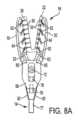
ここで図1を参照すると、本開示の種々の実施例に従って構築される、締結具アプリケータ10(本明細書では「外科手術用アプリケータ」または「アプリケータ」とも称される)は、その近位端13においてハンドルアセンブリ17と、その遠位端15において顎アセンブリ16とを有する、シャフト12を有し、個々の顎状部18、20は、締結具22(図2に示される)を担持するように適合される。ハンドルアセンブリ17は、初期位置と、作動位置と、初期位置と作動位置との間の中間位置との間でハンドル34に対して移動可能な、トリガ32を有する。トリガ32は、トリガ32上へのハンドル34に向かった方向(図1の矢印A)への圧縮力の印加に伴って、初期位置からハンドル34に対して移動可能である。本開示の種々の実施例では、締結具アプリケータ10は、組織構造にわたって締結具22を導入するために構成される。 Referring now to FIG. 1, a fastener applicator 10 (also referred to herein as a "surgical applicator" or "applicator"), constructed in accordance with various embodiments of the present disclosure, is constructed in accordance with various embodiments of the present disclosure. It has a
図2を参照すると、本開示の1つの非限定的実施例による、締結具22が、示される。締結具22は、締結具アプリケータ10の顎状部18、20が、開放しているとき、LAAまたは他の組織構造等の組織構造を受容するための、略U字形の構成を有する。締結具22は、圧縮可能な本体24と、2つの対向されたコンプライアントの組織係合表面28を有する、一対の平行な脚部26とを有する。脚部26は、開放または非固定位置と閉鎖または固定位置との間で移動可能である。いくつかの実施例では、脚部26はそれぞれ、軟質の生体適合性材料から成る。締結具22はさらに、脚部26に沿って離間され、組織係合表面28の第1のものから穿刺部位における組織を通して組織係合表面28の第2のものまで延在し、その間の組織構造を閉鎖するように配置される、複数の組織穿通締結具30を有する。複数の組織穿通締結具30は、組織構造に完全に接続されると、圧縮可能な本体24の軟質性および組織係合表面28間の距離の両方によって決定される、所望のレベルの圧縮力を印加する。組織構造に接続されると、締結具22は、組織構造を閉鎖および/またはシールするために定位置に残される。締結具22を越えて延在する組織構造の一部が、次いで、切断、切除、または別様に除去され得るが、これは、医師の選好に任せられ得る。本開示の締結具アプリケータ10との併用のために好適な種々の締結具のさらに詳細な説明が、米国特許第7,992,757号(その完全な開示は、参照することによって本明細書に組み込まれる)に説明される。 Referring to FIG. 2, a
ここで図3を参照すると、図1の締結具アプリケータ10の分解図が、示される。ハンドルアセンブリ17は、相互に結合され、ハンドルアセンブリ17の作用構成要素を受容するための内部空間を画定する、第1の筐体部分36aと、第2の筐体部分36bとを含む、筐体36を有する。第1の筐体部分36aおよび第2の筐体部分36bは、ともに組み立てられると、締結具アプリケータ10を取り扱うときにユーザによって握持される、ハンドル34を画定する。いくつかの実施例では、筐体36の第1および第2の部分36a、36bは、1つ以上のハンドル締結具38を使用して結合される。他の実施例では、筐体36の第1および第2の部分36a、36bは、クリップ、溝、接着剤、溶接、または任意の他の機械的締結配列を使用して結合されてもよい。種々の実施例では、筐体36の第1および第2の部分36a、36bは、相互に除去可能または非除去可能に結合されてもよい。 Referring now to FIG. 3, an exploded view of the
図3を継続して参照すると、筐体36の内部空間は、初期位置と、作動位置と、初期位置と作動位置との間の中間位置との間で外科手術用アプリケータ10を作動させるための種々の構成要素を受容する。例えば、筐体36は、種々の歯車、連結具、ばね、または同等物を受容し、初期位置と、作動位置と、初期位置と作動位置との間の中間位置との間でのトリガ32の移動または作動をもたらし得る。本明細書において議論されるように、筐体36は、トリガ枢動ピン44を中心とした枢動運動で筐体36に対して移動可能である、トリガ32の少なくとも一部を受容する。トリガ32は、トリガばね38等のトリガ付勢部材によって初期位置に付勢されてもよい。トリガばね38は、トリガ32上の押勢力が、除去される、またはトリガばね38の復元力を下回る大きさまで低減されると、トリガ32を初期位置まで復元させる、復元力が、トリガばね38において生成されるように、初期位置からのトリガ32の移動に伴って圧縮可能である。いくつかの実施例では、トリガ32は、筐体36の少なくとも一部に枢動可能に接続される、トリガ停止部40を有する。トリガ停止部40は、ハンドル34に対して第1の位置と第2の位置との間で移動可能であってもよい。トリガ停止部40は、トリガ停止部ばね50等のトリガ停止部付勢部材によって第1の位置に付勢される。 With continued reference to FIG. 3, the interior space of the
図3を継続して参照すると、筐体36は、本明細書に議論されるように、ラチェットロッド120と、ラチェット128とを有する、ラチェット機構46を受容する。ラチェット機構46は、トリガ32が中間位置から作動位置に向かって移動されると、係合し、初期位置に向かったトリガ32の移動を防止する。いくつかの実施例では、ラチェット機構46は、トリガ32が作動位置に到達すると、ラチェット機構46が係脱されるとき、またはトリガに印加される力が緩和されるときに、トリガ32が初期位置に向かって自動的に移動するように係脱する。減衰機構48が、筐体36内に受容され、トリガ32と動作可能に配列され、初期位置と作動位置との間での移動の間にトリガ32上に印加される圧縮力の変動を減衰させる。いくつかの実施例では、減衰機構48は、ダンパプランジャ52内に受容される、減衰ばね50と、ダンパ54とを有する。種々の実施例では、ダンパ54は、摩擦ダンパ、エラストマダンパ、磁気ダンパ、粘性ダンパ、またはそれらの任意の組み合わせであってもよい。 With continued reference to FIG. 3,
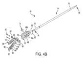
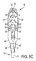
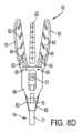
図4Aを参照すると、締結具アプリケータ10の残りの構成要素と別個である、顎アセンブリ16が、図示される。図4Bは、図4の顎アセンブリ16の分解図である。本明細書に説明されるように、顎アセンブリ16は、初期位置から作動位置までのトリガ32の移動を介して、開放位置(図4A-4Bに示される)と閉鎖位置(図8B-8Cに示される)との間で移動可能である。顎アセンブリ16は、相互に移動可能に取り付けられる、一対の顎状部18、20を備える。いくつかの実施例では、顎状部18、20は、ヒンジピン56およびワッシャ58を用いて相互に枢動可能に取り付けられる。いくつかの実施例では、ヒンジピン56およびワッシャ58は、レーザ溶接、超音波溶接、または他のタイプの溶接等を使用してともに溶接されてもよい。他の実施例では、ヒンジピン56およびワッシャ58は、相互と接着して接続される、相互と螺合可能に接続される、または任意の他の除去可能または非除去可能な機械的接続を用いて接続される。 Referring to FIG. 4A,
図4A-4Bを継続して参照すると、各顎状部18、20は、各側面60が、それを通して延在する、複数の側方スロット62を有する、一対の側面60を有する。側方スロット62は、顎カムピン64の移動を誘導するための、チャネルを画定する。単一の顎カムピン64が、各側方スロット62内に受容され、側方スロット62内で、第1の位置と第2の位置との間で移動可能である。第1の位置では、各顎状部18、20における顎カムピン64は、コーム66が、顎状部18、20内の伸長または暴露位置にあるように、スタッドコーム66に対して位置付けられる。第2の位置では、各顎状部18、20における顎カムピン64は、顎カムピン64が、各顎状部18、20におけるスタッドコーム66を引込または隠蔽位置まで押勢するように位置付けられ、コーム66は、締結具22の組織穿通締結具30に作用する。 With continued reference to FIGS. 4A-4B, each
図4A-4Bを継続して参照すると、顎状部18、20は、クランプボックス68内に受容される。いくつかの実施例では、クランプボックス68は、顎状部18、20を受容するためにその間に中心開口部70を画定する、一対の側面68a、68bを有する。クランプボックス68の側面68a、68bは、1つ以上のリベット72等によって相互に除去可能または非除去可能に接続されてもよい。開放位置と閉鎖位置との間の顎状部18、20の移動は、顎状部18、20のそれぞれの上の誘導スロット63とクランプボックス68上の対応する誘導ピン65(図4Bに示される)との間の相互作用によって誘導される。 With continued reference to FIGS. 4A-4B, the
クランプボックス68は、クランプ管76の遠位端等、シャフト14の少なくとも一部の遠位端74を受容する。図4C-4Eを参照すると、シャフト14は、クランプ管、排出管77、および内側プルロッド78が、相互に対して同軸に配置されるように、排出管77内に摺動可能に受容される、クランプ管76と、クランプ管76内に摺動可能に受容される、内側プルロッド78とを備える。クランプ管76は、クランプボックス68および顎状部18、20を回転させるようにその縦軸を中心として回転可能であり、それによって、締結具アプリケータ10の使用の間にハンドルアセンブリ17に対する顎状部18、20の配向を促進し得る。いくつかの実施例では、シャフト14は、位置付けノブ88(図5に示される)の回転に伴って、その縦軸を中心として回転可能である。
プルロッド78は、トリガ32の移動に伴ってクランプ管76に対して軸方向に移動可能である。例えば、プルロッド78は、シャフト14の近位端と遠位端との間に延在する方向に、その縦軸に沿って移動可能であってもよい。初期位置から作動位置に向かったトリガ32の移動または閉鎖は、プルロッド78をクランプ管76および排出管77に対してシャフト14の近位端80に向かって近位に引き寄せ、これは、ひいては、顎状部18、20を閉鎖する。排出管77は、その遠位端に接続される、少なくとも1つのテンドン82を有する。少なくとも1つのテンドン82は、アクティブ化位置へのトリガ32の移動がまた、少なくとも1つのテンドン82を引動し、コームスタッド66の引込を引き起こすように、コームスタッド66と動作可能に接続される。 The
図4A-4Bを参照すると、各顎状部18、20の側面60のうちの少なくとも1つの外部表面は、陥凹84を有する。陥凹84は、側方スロット62を囲繞する領域における側面60から各顎状部18、20の本体の中に延在する、チャネルとして形成されてもよい。いくつかの実施例では、陥凹84は、複数の側方スロット62の少なくとも一部を封入する、カバー要素86(図3にも示される)を受容する。カバー要素86の厚さは、カバー要素86の外部表面が、側面60の表面と同一平面状であり得るように選定されてもよい。他の実施例では、カバー要素86の厚さは、その外部表面が、側面60の表面に対して陥凹されるように、またはカバー要素86の外部表面が、側面60の表面から側方に突出するように選定されてもよい。いくつかの実施例では、カバー要素86は、陥凹84の中に接着して固着されてもよい。さらなる実施例では、カバー要素86は、側方スロット62および顎カムピン64が、カバー要素86を通して見え得るように透明であってもよい。陥凹84の中に位置付けられると、カバー要素86は、1つ以上の側方スロット62の閉塞を引き起こす、および/または側方スロット62を通した1つ以上の顎カムピン64の移動を妨げ得る、締結具アプリケータ10の使用の間の側方スロット62および顎カムピン64の汚染を防止する。 4A-4B, the exterior surface of at least one of the sides 60 of each
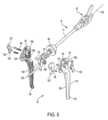
図5を参照すると、トリガ32は、相互に結合される、第1のトリガ部分32aと、第2のトリガ部分32bとを含む。第1のトリガ部分32aおよび第2のトリガ部分32bは、ともに組み立てられると、締結具アプリケータ10を取り扱うときにユーザによって握持される、トリガ32を画定する。いくつかの実施例では、第1および第2のトリガ部分32a、32bは、1つ以上のトリガ締結具90を使用して結合される。他の実施例では、第1および第2のトリガ部分32a、32bは、クリップ、溝、接着剤、溶接、圧入、または任意の他の機械的締結配列を使用して結合されてもよい。種々の実施例では、第1および第2のトリガ部分32a、32bは、相互に除去可能または非除去可能に結合されてもよい。 Referring to FIG. 5, trigger 32 includes a first trigger portion 32a and a
図5を継続して参照すると、各トリガ部分32a、32bは、筐体36(図3に示される)内に受容され、筐体36に対して枢動可能に移動可能である、第1の端部92を有する。第2の自由端94が、第1の端部92の反対に延在し、筐体36の外側に突出する。トリガ32の第2の自由端94は、初期位置とアクティブ化位置との間でのトリガ32の移動の間にユーザによって握持されるために構成される。トリガ32はさらに、ハンドルに面する近位側108の反対の、遠位側110を有する。本明細書に説明されるように、ロックアウト機構の少なくとも一部が、トリガ32の遠位側110に位置付けられる。 With continued reference to FIG. 5, each
図5を継続して参照すると、トリガ32は、トリガ枢動ピン44(図3に示される)を受容するために構成される、枢動ピン開口部112を有する。トリガ32は、筐体36に固着されるその終端を有する、トリガ枢動ピン44の縦軸を中心として枢動可能に移動可能である。トリガスロット114が、トリガ32の第1の端部92における本体を通して延在する。トリガスロット114は、プルロッド78の遠位端に接続される閉鎖トラニオン116を受容するように構成される。トリガスロット114は、トリガスロット114内での閉鎖トラニオン116の移動に起因するプルロッド78の移動を制御するためのカム作用機構として作用する。いくつかの実施例では、トリガスロット114の形状は、トリガ枢動ピン44を中心としたトリガの枢動移動の結果として、シャフト14の縦軸118の方向のプルロッド78の線形移動をもたらすように構成される。閉鎖トラニオン116は、トリガ32が、初期位置(図7A)にあるときに、トリガスロット114の第1の端部と接触する、またはほぼ接触するように位置付けられてもよい。同様に、閉鎖トラニオン116は、トリガ32が、作動位置(図7E)にあるときに、トリガスロット114の(第1の端部の反対の)第2の端部と接触する、またはほぼ接触するように位置付けられてもよい。閉鎖トラニオン116は、トリガ32が、初期位置と作動位置との間の中間位置にあるときに、トリガスロット114の第1の端部と第2の端部との間に位置付けられてもよい。排出トラニオン164の側方ピンが、トリガ32の移動がまた、トリガスロット114(図10A-10C参照)内での排出トラニオン164の移動に起因するトリガサブレバー122の対応する移動を引き起こすように、トリガサブレバー122の第1の端部(図10A-10Cも参照)の第1の端部を通して延在する、開口部123内に受容される。 With continued reference to FIG. 5, the
図5を継続して参照すると、トリガサブレバー122の第2の端部が、トリガ32に枢動可能に接続される、ピン125を有する。このように、トリガサブレバー122の第1の端部は、トリガスロット166および排出トラニオン164に対して摺動可能に移動可能である一方で、トリガサブレバー122の第2の端部は、ハンドル34(図10A-10C参照)上のトリガサブ停止特徴172に対して枢動可能に移動可能である。トリガサブレバー122の第2の端部が、ハンドル34上のトリガサブ停止特徴172に衝打し、トリガ32が、作動位置に向かって近位に移動し続けると、トリガサブレバー122の第1の端部の相対運動が、ピン125を中心として枢動することによって増幅される。増幅は、図10Bの2つの距離L1およびL2の比率によって決定される。L1は、トリガサブ停止特徴172とトリガサブレバーピン125との間の距離である一方で、L2は、トリガサブレバーピン125と排出トラニオン164との間の距離である。トリガサブレバー122は、トリガサブレバースロット170を介して排出トラニオン164に影響を及ぼす。このように、トリガ32の第1の(小さい)移動は、排出トラニオン164が排出管77に連結されていることに起因して、排出トラニオン164上に第2の(より大きい)移動を有することができる。このように、コーム66は、テンドン82を介して引込され、締結具22(図2に示される)を解放することができる。 With continued reference to FIG. 5, a second end of
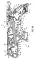
図6Aを参照すると、締結具アプリケータ10は、係止位置と係止解除位置との間でトリガ32に対して移動可能な、ロックアウト機構140aを有する。図6Aのロックアウト機構140aは、本開示の一実施例に従って示される。ロックアウト機構140aは、トリガ32が、初期位置から作動位置に向かって移動されると、トリガ32を中間位置(図7B)に係止するように動作可能に配列される。ロックアウト機構140aはさらに、ロックアウト機構が、係止位置から係止解除位置(図7C)まで移動されると、中間位置から初期位置または作動位置に向かったトリガ32の移動を許可するように動作可能に配列される。ロックアウト機構140aはさらに、トリガ解放ボタン96が、初期位置からのトリガ32の移動に先立って第1の位置から第2の位置まで移動されると、初期位置にトリガ32を係止するように動作可能に配列される。 Referring to FIG. 6A,
図6Aを継続して参照すると、ロックアウト機構140aは、トリガ解放ボタン96と、トリガ停止部40と、ラチェット機構46とを備える。本明細書に説明されるように、初期位置から作動位置に向かったトリガ32の移動は、トリガ32をトリガ停止部40と係合させ、トリガ停止部40を移動させ、中間位置にトリガ32を自動的に係止する。中間位置からトリガ32を解放するために、トリガ32が中間位置にあるときのトリガ解放ボタン枢動ピン100を中心とした、第1の位置から第2の位置までのトリガ解放ボタン96の移動が、トリガ32からのトリガ停止部40の係脱を許可する。このように、トリガ32は、トリガばね38の復元力に起因して初期位置まで引込される、または作動位置まで移動され、締結具22(図2に示される)を閉鎖することができる。 With continued reference to FIG. 6A,
トリガ解放ボタン96は、第1の端部92と第2の自由端94(図5)との間のトリガ32上の開口部98を通して延在する。種々の実施例では、トリガ解放ボタン96は、トリガ解放ボタン96が、トリガ解放ボタン96の押圧面97に接触するユーザの人差し指を使用して動作され得るように、トリガ32の第1および第2の端部92、94に対して位置付けられる。トリガ解放ボタン96は、トリガ解放ボタン96が開口部98から突出する、第1の位置と、トリガ解放ボタン96の少なくとも一部がトリガ上の開口部98の中に移動される、第2の位置との間で移動可能である。いくつかの実施例では、トリガ解放ボタン96は、第1の位置および第2の位置における開口部98から突出してもよい。
トリガ解放ボタン96は、第1のトリガ解放ボタン枢動ピン100を中心として、第1の位置と第2の位置との間でトリガ32に対して枢動可能に移動可能である。他の実施例では、トリガ解放ボタン96は、締結具アプリケータ10の近位/遠位方向またはトリガ32に対する横方向の移動等によって、トリガ32に対して線形に移動可能であってもよい。トリガ解放ボタン96におけるトリガ解放ボタンスロット104は、第2のトリガ解放ボタンピン106を受容し、トリガ解放ボタン96の移動範囲を定めてもよい。第2のトリガ解放ボタンピン106は、トリガ解放ボタン96が、第1の位置にあるとき、トリガ解放ボタンスロット104の第1の端部と接触する、またはそれとほぼ接触するように位置付けられてもよい。同様に、第2のトリガ解放ボタンピン106は、トリガ解放ボタン96が、第2の位置にあるとき、トリガ解放ボタンスロット104の(第1の端部の反対の)第2の端部と接触する、またはそれとほぼ接触するように位置付けられてもよい。
トリガ解放ボタン96は、トリガ解放ボタンばね102等の解放ボタン付勢部材によって第1の位置に付勢される。トリガ解放ボタンばね102は、トリガ解放ボタン96上の押勢力が、除去され、トリガ解放ボタン96が、トリガ停止部40から接続解除されると、トリガ解放ボタン96を第1の位置まで復元させる、復元力が、トリガ解放ボタンばね102において生成されるように、第1の位置から第2の位置に向かったトリガ解放ボタン96の移動に伴って圧縮可能である。
図6Aを継続して参照すると、トリガ解放ボタン96は、トリガ解放ボタン96の第2の自由端95に位置付けられ、トリガ解放ボタン96が、トリガ32が中間位置まで移動される前に押圧される場合に、トリガ停止部40の少なくとも一部に係合し、初期位置からのトリガ32の移動を防止するために構成される、停止部材150を有する。このように、トリガ32は、トリガ解放ボタン96が、押圧されない場合に限り、初期位置から移動されることができる。いくつかの実施例では、停止部材150は、トリガ解放ボタン96の第2の端部における、丸みを帯びた先端として構成されてもよい。 With continued reference to FIG. 6A, the
図6Aを継続して参照すると、トリガ解放ボタン96は、第1のトリガ解放ボタン枢動ピン100と停止部材150との間に位置付けられる、トリガ停止部解放部材152を有する。トリガ停止部解放部材152は、トリガ32が、初期位置と作動位置との間の中間位置に位置付けられると、トリガ停止部40の少なくとも一部に係合するために構成される。トリガ32が中間位置にあるときにトリガ解放ボタン96を押圧することは、トリガ停止部解放部材152をトリガ停止部40と係合させ、トリガ停止部40を係止解除し、中間位置から作動位置または初期位置に向かったトリガ32の移動を許可する。いくつかの実施例では、トリガ停止部解放部材152は、第1のトリガ解放ボタン枢動ピン100と停止部材150との間のトリガ解放ボタン96の近位部分における、丸みを帯びた突出部として成形されてもよい。 With continued reference to FIG. 6A,
トリガ解放ボタン96aの非限定的な例示的実施形態が、図11に示される。トリガ解放ボタン96aの実施形態は、押圧面97aと、トリガ解放ボタンスロット104aと、停止部材150aとを含む。図11に示されるトリガ解放ボタン96aの実施形態では、押圧面97aは、ユーザがトリガ解放ボタンを位置特定するための明確に異なる表面および増加された把持をユーザに提供し、それによって、締結具アプリケータをより使用し易くする、隆起された交差パターン197を含む。トリガ解放ボタン96aの本非限定的な例示的実施形態は、図6A、6B、および7A-7Eに示される締結具アプリケータの実施形態を含む、本開示の締結具アプリケータの実施形態において使用されることができる。 A non-limiting exemplary embodiment of a trigger release button 96a is shown in FIG. The embodiment of trigger release button 96a includes a
図6Aを継続して参照すると、トリガ停止部40は、ハンドル34に接続され、第1の位置(図7A)と第2の位置(図7E)との間でハンドル34に対して移動可能である。トリガ停止部40は、減衰ばね50(図3)等のトリガ停止部付勢部材によって第1の位置に付勢される。いくつかの実施例では、トリガ停止部40は、トリガ停止部ピン142を中心として、第1の位置と第2の位置との間でハンドル34に対して枢動可能に移動可能である。トリガ停止部40は、トリガ停止部ピン142を中心として枢動可能である、第1の端部144と、第1の端部144の反対の、第2の自由端146とを有する。 With continued reference to FIG. 6A,
トリガ停止部40の少なくとも一部は、トリガ停止部40が、第1の位置にあるとき、ハンドル34の筐体36内に陥凹され得る。例えば、トリガ停止部40の第1の端部144および第2の端部146は、トリガ停止部40が、第1の位置にあるとき、ハンドル34の筐体36内に陥凹されてもよい。いくつかの実施例では、トリガ停止部40の少なくとも一部は、トリガ停止部40が、第1の位置から第2の位置に向かって枢動されると、ハンドル34の筐体36から延在し得る。例えば、トリガ停止部40の第1の端部144は、ハンドル34の筐体36の内部内に陥凹され得る一方で、トリガ停止部40の第2の端部146の少なくとも一部は、トリガ停止部40が、第1の位置から第2の位置に向かって枢動されると、筐体36の内部から突出する。 At least a portion of
図6Aを継続して参照すると、トリガ停止部40は、トリガ32が中間位置から作動位置に向かって移動されると減衰機構48と相互作用するために構成される、減衰カム148を有する。減衰カム148は、トリガ停止部40の第1の端部144に位置付けられ、中間位置と作動位置との間のトリガ32のストロークの間に減衰ばね50(図3に示される)および減衰プランジャ52の変位量を変動させるように成形される。減衰プランジャ52が、減衰ばね50の復元力に対して圧縮されるにつれて、減衰プランジャ52は、ダンパ54(図7Eに示される)に係合する。いくつかの実施例では、トリガ停止部40上の減衰カム148および減衰機構48は、中間位置から最終位置に向かったトリガ32の移動の間に、そのストロークの間の中間位置と最終位置との間のトリガ32の位置にかかわらず、トリガ32上の持続的抵抗力を要求するように構成されてもよい。このように、ユーザは、締結具アプリケータ10のアクティブ化の間に、組織構造に対して顎アセンブリ16(図1に示される)の位置を意図せずに変化させ得る、トリガ32上に入力される力を変動させる必要はない。 With continued reference to FIG. 6A, the
図6Aを継続して参照すると、トリガ停止部40の第2の端部146は、トリガ32が初期位置に位置付けられている間に、トリガ解放ボタン96が押圧される場合、トリガ解放ボタン96の停止部材150に係合するために構成される、第1の停止部材係合面154を有する。トリガ停止部40の第1の停止部材係合面154とトリガ解放ボタン96の停止部材150との間の接触は、トリガ解放ボタン96が、トリガ32が中間位置まで移動される前に押圧される場合、初期位置から作動位置に向かったトリガ32の移動を防止する。このように、トリガ32は、トリガ解放ボタン96が、解放され、それによって、トリガ解放ボタン96の停止部材150からトリガ停止部40の第1の停止部材係合面154を係脱させるまで、初期位置に係止される。いくつかの実施例では、トリガ停止部40の第1の停止部材係合面154は、トリガ停止部40の第2の端部146の終端部分における、陥凹として構成されてもよい。 With continued reference to FIG. 6A, the
中間位置までのトリガ32の移動は、トリガ停止部40上のトリガ掛け金(latch)156とトリガ32上のトリガ留め金(catch)158の係合に起因して、ハンドル34に対してトリガ32を係止する。いくつかの実施例では、トリガ停止部40上のトリガ掛け金156は、トリガ停止部40の少なくとも1つの側面から離れるように側方に延在する、少なくとも1つの突出部として構成される。いくつかの実施例では、トリガ掛け金156は、トリガ停止部40の対向する側面から離れるように側方に延在する、一対の突出部である。トリガ32上のトリガ留め金158は、トリガ掛け金156の少なくとも一部を受容するように成形される、トリガ32の近位側108における、陥凹として構成されてもよい。 Movement of
トリガ掛け金156およびトリガ留め金158は、トリガ32が、中間位置まで移動されると係合し、初期位置または作動位置に向かったトリガ32の移動を防止する。トリガ掛け金156およびトリガ留め金158は、トリガ解放ボタン96を押圧することによって係脱され、それによって、トリガ解放ボタン96の少なくとも一部は、トリガ停止部40の少なくとも一部に接触し、トリガ停止部40を移動させ、トリガ32上のトリガ留め金158との接触からトリガ掛け金156を変位させる。いくつかの実施例では、トリガ解放ボタン96の停止部材150は、トリガ停止部40上の解放面160に係合し、トリガ停止部40を移動させ、トリガ32上のトリガ留め金158との接触からトリガ掛け金156を変位させる。解放面160は、トリガ停止部40の第2の端部146に、かつ停止部材150の近位に位置付けられてもよい。
図6Aを継続して参照すると、トリガ停止部40は、第2の停止部材係合面155および解放面160の近位に位置付けられる、トリガ作動面162を有する。トリガ停止部40のトリガ作動面162は、トリガ解放ボタン96が押圧されている間にトリガ32が中間位置から作動位置に向かって移動されると、トリガ解放ボタン96のトリガ停止部解放部材152に係合するために構成される。トリガ32が中間位置から作動位置に向かって移動されるときにトリガ解放ボタン96を押圧することは、トリガ停止部解放部材152をトリガ停止部40のトリガ作動面162と係合させ、トリガ停止部40を係止解除し、作動位置に向かったトリガ32の移動を許可する。いくつかの実施例では、トリガ作動面162は、トリガ解放ボタン96のトリガ停止部解放部材152に係合する、傾斜部として成形されてもよい。トリガ作動面162が、スロットとして成形される、実施例では、トリガ作動面162は、トリガ作動面162に沿ったトリガ停止部解放部材152の移動のためのクリアランスを提供する。 With continued reference to FIG. 6A,
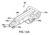
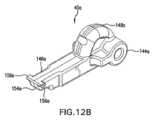
トリガ停止部40aの非限定的な例示的実施形態が、図12Aおよび12Bに示される。トリガ停止部40aの実施形態は、第1の端部144aと、第2の端部146aと、減衰カム148aと、第1の停止部材係合面154aと、トリガ掛け金156aと、解放面160aと、トリガ作動面162aとを含む。トリガ停止部40aの本非限定的な例示的実施形態は、図6A、6B、および7A-7Eに示される締結具アプリケータの実施形態を含む、本開示の締結具アプリケータの実施形態において使用されることができる。 A non-limiting exemplary embodiment of
図6Aを継続して参照すると、ロックアウト機構140aはさらに、トリガ32が中間位置から作動位置に向かって移動されると係合する、ラチェット機構46を備える。ラチェット機構46は、トリガ32が中間位置から作動位置に向かって移動された後の、初期位置に向かったトリガ32の移動を防止するように構成される。いくつかの実施例では、ラチェット機構46は、トリガ32が、中間位置から作動位置に向かって所定の位置だけ移動されると作動される。さらなる実施例では、ラチェット機構46は、トリガ解放ボタン96が押圧されている間にトリガ32が中間位置から作動位置に向かって移動されるにつれて、トリガ停止部40のトリガ作動面162が、トリガ解放ボタン96のトリガ停止部解放部材152に係合すると作動される。さらなる実施例では、ラチェット機構46は、トリガ32が作動位置に到達し、トリガ32の初期位置に向かって戻るような移動を許可すると、自動的に係脱するように構成される。 Continuing to refer to FIG. 6A, the
ラチェット機構46は、トリガ32が中間位置から作動位置に向かって移動されるとラチェットレバー128と選択的に係合可能である、ラチェットロッド120を備える。ラチェットロッド120は、トリガ32が、中間位置(図7A)から作動位置(図7E)に向かって枢動するにつれて、遠位から近位の方向に軸方向に移動可能である。ラチェットロッド120は、結合器131(図5に示される)を介してトリガ32に連結される。ラチェットロッド120は、ピン168(図5に示される)を中心としてトリガ32に対して枢動することができる。ラチェットレバー128は、初期位置(図7A)と係合位置(図7D-7E)との間で移動可能である。いくつかの実施例では、ラチェットレバー128は、ラチェット枢動ピン132を中心として枢動可能である。ラチェットレバー128は、ラチェットレバーばね134等のラチェットレバー付勢機構によって初期位置に向かった方向に付勢されてもよい。初期位置(図7A)から作動位置(図7E)に向かってトリガ32を移動させることは、シャフト14の縦軸118の近位方向のプルロッド78の軸方向の移動、および近位方向のラチェットロッド120の軸方向の移動をもたらす。
図6Aを継続して参照すると、ラチェットロッド120の近位端は、ラチェットレバー128と相互作用する、1つ以上の歯130を有する。中間位置から作動位置に向かったトリガ32の移動に起因する近位方向におけるラチェットロッド120の移動は、ラチェットロッド120の近位端をラチェットレバー128と係合させる。ラチェットロッド120の近位端とラチェットレバー128との間の初期の接触は、ラチェットレバーばね134に対してラチェットレバー128を枢動させることによって、係脱位置から係合位置に向かってラチェットレバー128を変位させる。 With continued reference to FIG. 6A, the proximal end of
ラチェットロッド120の1つ以上の歯130は、トリガ32が、中間位置から作動位置に向かって移動され、中間位置から初期位置に向かったトリガ32の移動を防止すると、ラチェットレバー128の係止先端136に係合する。ラチェットロッド120は、トリガ32が、(例えば、図7Aの構成から図7Eの構成までの)トリガ32のための閉鎖の方向におけるラチェットレバー128下でラチェットロッド120をより完全に駆動することによって、徐々に閉鎖され(すなわち、ハンドル32に接近するようにもたらされ)得るように、任意の数の歯を含むことができる。 The one or
いくつかの実施例では、ラチェットレバー128は、トリガ32が作動位置に到達することに先立ってラチェットロッド120に係合し、作動位置から初期位置に向かったトリガの逆移動を防止し得る。例えば、ラチェットロッド120の近位端は、ラチェットレバー128の近位端における、ラチェットレバー係合面138に接触することができる。ラチェットレバー係合面138は、ラチェットロッド120の近位移動がラチェットレバー128を枢動させるように角度付けられてもよい。いくつかの実施例では、ラチェットレバー128は、ラチェットレバー128上の1つ以上の係止タブ139と筐体36の少なくとも一部の係合に起因して係止されることができる。いくつかの実施例では、1つ以上の係止タブ139は、ラチェットレバー128がラチェット枢動ピン132を中心として自由に枢動し得る、第1の位置と、ラチェットレバー128が、筐体36に対して係止される、第2の位置との間で側方に偏向可能であってもよい。1つ以上の係止タブ139は、筐体36に衝打し、したがって、音量が大きいクリック音を引き起こし、トリガ32が作動位置に到達していること、および顎状部18、20が閉鎖されていることをユーザに可聴に警報してもよい。本可聴の確認は、締結具22が閉鎖されていること、およびトリガ32が解放され得ることをユーザに示す。いったんラチェットレバー128の1つ以上の係止タブ139が、筐体36に係合すると、ラチェットレバー128は、ラチェットロッド120に対して係脱された状態で係止される。 In some embodiments, the
ラチェットレバー128aの非限定的な例示的実施形態が、図13Aおよび13Bに示され、ラチェットレバー128aは、係止先端136aと、2つの係止タブ139aとを含む。ラチェットレバー128aの本非限定的な例示的実施形態は、図6A、6B、および7A-7Eに示される締結具アプリケータの実施形態を含む、本開示の締結具アプリケータの実施形態において使用されることができる。 A non-limiting exemplary embodiment of
図6Bを参照すると、締結具アプリケータ10が、本開示の別の実施例によるロックアウト機構140bとともに示される。図6Bに示されるロックアウト機構140bの構成要素は、図6Aを参照して本明細書に説明される、ロックアウト機構140aの構成要素に実質的に類似する。概して図6Aに示されるロックアウト機構140aに関する前述の議論が、図6Bに示されるロックアウト機構140bに適用可能であるので、2つのロックアウト機構間の相対差のみが、以降に議論される。 Referring to FIG. 6B,
図6Bを継続して参照すると、トリガ解放ボタン96は、トリガ解放ボタン96の第2の自由端95に位置付けられ、トリガ32が中間位置まで移動されるときにのみトリガ停止部40の少なくとも一部に係合するために構成される、停止部材150を有する。図6Aに示されるトリガ解放ボタン96およびトリガ停止部40とは異なり、図6Bのトリガ解放ボタン96およびトリガ停止部40は、トリガ解放ボタン96が、トリガ32が初期位置から移動される前に押圧される場合でも、初期位置からのトリガ32の移動を可能にするように構成される。言い換えると、トリガ解放ボタン96が、押圧され、保持される場合、トリガ32は、停止することなく中間位置を通して、最終的には、作動位置まで通過することができる。 With continued reference to FIG. 6B, the
図6Bを継続して参照すると、トリガ解放ボタン96のトリガ停止部解放部材152は、トリガ32が初期位置と作動位置との間の中間位置に位置付けられるときにトリガ停止部40の少なくとも一部に係合するために構成される。トリガ32が中間位置にあるときにトリガ解放ボタン96を押圧することは、トリガ停止部解放部材152をトリガ停止部40と係合させ、トリガ停止部40を係止解除し、中間位置から作動位置に向かったトリガ32の移動を許可する。いくつかの実施例では、トリガ32が初期位置にあるときにトリガ解放ボタン96を押圧することは、トリガ停止部解放部材152をトリガ停止部40と係合させ、トリガ停止部40を係止解除し、初期位置から作動位置に向かったトリガ32の移動を許可し、それによって、中間位置でのトリガ32の係止をバイパスする。 With continued reference to FIG. 6B, the trigger
図6Bを継続して参照すると、トリガ停止部40の第1の停止部材係合面154は、トリガ停止部40の第2の端部146の終端部分における、略平面状部分として構成される。同様に、第2の停止部材係合面155は、図6Aに示される陥凹状構成と対照的に、略平面状であってもよい。中間位置から作動位置に向かってトリガ32を移動させることに先立ってトリガ解放ボタン96を押圧することは、トリガ停止部解放部材152をトリガ停止部40の第2の停止部材係合面155およびトリガ作動面162と係合させ、トリガ停止部40を係止解除し、作動位置に向かったトリガ32の移動を許可する。 With continued reference to FIG. 6B, the first stop
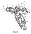
締結具アプリケータ10の構造を説明したので、組織構造にわたって締結具22を閉鎖するための締結具アプリケータ10の使用方法が、ここで、図7A-8Dおよび10A-10Cを参照して説明されるであろう。初めに図7Aを参照すると、締結具アプリケータ10は、トリガ32が、初期位置に位置付けられ、顎状部18、20(図8Aに示される)が、その間に締結具22を受容するような開放構成にある、初期の、すなわち、送達時の構成で示される。締結具22が、LAA等の組織構造にわたって前進された後、顎状部18、20は、図7Bの矢印Aの方向にハンドル34に向かってトリガ32を手動で移動させることによって閉鎖される。トリガ32は、トリガ32の遠位側110上に、矢印Aの方向に近位に指向される力を指向することによって、初期位置(図7A)からハンドル34に向かって移動されることができる。 Having described the structure of
ハンドル34に対してトリガ32を閉鎖すること、すなわち、トリガ32(図10Aまたは図7Aに示される)の初期位置からトリガ枢動ピン44を中心として枢動させることは、プルロッド78をクランプ管76に対してシャフト14の近位端に向かって近位に引き寄せ、これは、ひいては、顎状部18、20(図8B)を閉鎖する。トリガ32は、トリガ32が、中間位置を越えて前進されない限り、組織構造に対する締結具22の位置付けの間、近位方向に移動され、顎状部18、20を閉鎖する、または遠位方向に移動され、顎状部18、20を開放することができる。これは、ユーザが、締結具22を閉鎖することなく組織構造に対して締結具22を慎重に位置付けることを可能にする。 Closing the
図7Bを参照すると、トリガ32が、トリガ32がトリガ停止部40上のトリガ掛け金156とトリガ32上のトリガ留め金158の係合に起因してハンドル34に対して一時的に係止される、中間位置に示される。トリガ32が、中間位置まで移動され、その中に係止されると、初期位置または作動位置に向かったトリガ32のさらなる移動が、トリガ解放ボタン96を介したさらなるユーザ入力がなければ防止される。トリガ32が中間位置に係止された状態では、顎状部18、20が、「プレビュー」位置で閉鎖され、締結具22の脚部26は、相互に向かって持っていかれ、組織穿通締結具30(図8A)に係合することなくその間に組織構造を捕捉する。これは、ユーザが締結具22を閉鎖することなく組織構造に対する締結具22の位置をプレビューすることを可能にする。 Referring to FIG. 7B, the
組織構造に対する締結具22の再位置付けが、必要である場合、トリガ32は、トリガ解放ボタン96を押圧し、トリガ留め金158(図7C)からトリガ掛け金156を係脱させることによって係止解除されることができる。トリガ解放ボタン96を押圧することによって、トリガ解放ボタン96の停止部材150等のトリガ解放ボタン96の少なくとも一部は、トリガ停止部40上の解放面160等、トリガ停止部40の少なくとも一部に接触し、トリガ停止部40を移動させ、トリガ32上のトリガ留め金158との接触からトリガ掛け金156を変位させる。トリガ32は、次いで、トリガばね42(図3に示される)の復元力に起因してハンドル34に対して遠位に移動されることができる。初期位置に向かった、かつハンドル34から離れるようなトリガ32の移動は、顎状部18、20を開放し、締結具22の再位置付けを可能にする。 If repositioning of the
ここで図7Dを参照すると、締結具アプリケータ10が、締結具22が組織構造に対して所望の位置に配列されるように配向される場合、トリガ32は、トリガ解放ボタン96を押圧し、トリガ留め金158からトリガ掛け金156を係脱させることによって、中間位置から係止解除される。トリガ32は、次いで、矢印Aの方向にトリガ32を移動させることによって、ハンドル34に向かって近位に前進されることができる。ハンドル34に対してトリガ32を閉鎖することは、ハンドル34に対して第1の位置(図7C)から第2の位置(図7E)までトリガ停止部40を移動させ、作動位置に向かったトリガ32のさらなる近位移動を可能にする。 Referring now to FIG. 7D, when the
ハンドル34に対してトリガ32を閉鎖することはまた、トリガ32に連結されるラチェットロッド120を近位に引込させる。トリガ32が作動位置に位置付けられる、図10Cを参照すると、トラニオン116は、トラニオン116の中心、したがって、開口部123が、図10Aに示される第1の所定の距離X1よりも大きい第2の所定の距離X2だけトリガ枢動ピン44の中心から近位に離間されるように、トリガスロット114の近位端まで移動する。トリガサブレバー122は、その終端がラチェットロッド120に接触し、ラチェットロッド120を近位方向に前進させるように配向される。中間位置を越えたトリガ32の移動に起因したラチェットロッド120の近位移動は、ラチェットロッド120の歯130を係止レバー128の係止先端136と係合させ、それによって、ラチェット機構46をアクティブ化させる。いったんラチェット機構46が、係合されると、初期位置(図7A)に向かった方向へのトリガ32の引込が、防止される。このように、ユーザは、作動位置に向かってトリガ32を完全に係合させることによって、組織構造上で締結具22を閉鎖することが確約される。 Closing
中間位置から作動位置に向かったトリガ32の閉鎖はさらに、プルロッド78をクランプ管76に対してシャフト14の近位端に向かって近位に引き寄せる。排出管77は、少なくとも1つのテンドン82を引動し、コームスタッド66を引込させる。顎状部18、20が、閉鎖されると、スタッドコーム66は、図8Cに示されるように、相互と係合および係止し、したがって、締結具22の2つの脚部26を閉鎖するように、組織穿通締結具30に係合する。 Closure of
トリガ32が、中間位置から作動位置に向かって前進されるにつれて、トリガ停止部40は、トリガ32によって第1の位置(図7A)から第2の位置(図7E)に向かって偏向される。トリガ停止部40が、第1の位置から第2の位置まで移動するにつれて、トリガ停止部40の減衰カム148は、減衰機構48のダンパプランジャ52に接触し、それによって、減衰ばね50(図3に示される)を圧縮する。減衰プランジャ52が、減衰ばね50の復元力に対して圧縮されるにつれて、減衰プランジャ52は、ダンパ54(図7Eに示される)に係合し、これは、トリガ32に矢印Aの方向に指向される圧縮力に対する抵抗を提供する。本明細書に説明されるように、トリガ停止部40上の減衰カム148および減衰機構48は、ユーザが、中間位置と作動位置との間のそのストロークの間のトリガ32の位置にかかわらず、中間位置から最終位置に向かったトリガ32の移動の間にトリガ32から実質的に一定の反力を感知するように構成される。例えば、ユーザは、トリガ32をハンドル34に向かって矢印Aの方向に移動させる間、トリガ32から実質的に一定の反力を知覚し、それによって、中間位置から作動位置に向かったトリガ32の移動の間にトリガ32上に実質的に一定の圧縮力を要求し得る。 As
ここで図7Eを参照すると、トリガ32は、作動位置まで移動され、ラチェット機構46からトリガ32を解放し、初期位置に向かったトリガ32の引込を可能にする。本明細書に説明されるように、ラチェットロッド120の近位端は、ラチェットレバー128の近位端においてラチェットレバー係脱面138に接触し、これは、ラチェットロッド120からラチェットレバー128を持ち上げ、ラチェットレバー128上の1つ以上の係止タブ139と筐体36の少なくとも一部の相互作用に起因する、ラチェットロッド120との再係合を防止する。顎状部18、20は、トリガ32上に手動の圧縮を解放することによって開放され、それによって、トリガばね38およびトリガ32の閉鎖の間に圧縮されていた主ばね42がラチェットロッド120を遠位に前方に押動し、顎状部18、20を開放し、締結具22を定位置(図8D)に残すことを可能にし得る。 Referring now to FIG. 7E, trigger 32 is moved to the actuated position, releasing
ここで図9を参照すると、1つの具体的な使用実施例が、図示される。本実施例では、締結具アプリケータ10が、開胸式の心拍動下手技において左心耳LAAの基部にわたって締結具22を送達するために使用される。胸骨Sが、開放され、肋骨を広げ、心臓Hにわたって作業空間を提供する。心膜を開放した後、心臓Hは、図9に示されるように、例えば、心臓の背後に配置されるガーゼまたは他の材料のシートを使用して持ち上げられ、方向転換され、開口部内に左心耳LAAを暴露し得る。左心耳LAAが、暴露された後、締結具アプリケータ10の顎状部18、20が、シャフト12を操作することによって左心耳LAAの基部の周囲に設置される。いったん顎状部18、20が、左心耳LAAの基部を中心として締結具22を適切に位置付けると、顎状部18、20は、作動され、締結具22は、前述に説明されるように展開される。 Referring now to FIG. 9, one specific example of use is illustrated. In this example,
本発明は、現在最も実践的かつ好ましい実施例として見なされるものに基づいて例証の目的のために詳細に説明されているが、そのような詳細が、その目的のためのものにすぎず、本発明が、開示される実施例に限定されず、むしろ、添付の請求項の精神および範囲内である、修正および同等の配列を網羅することが意図されていることを理解されたい。例えば、本発明が、可能性として考えられる範囲で、任意の実施例の1つ以上の特徴が、任意の他の実施例の1つ以上の特徴と組み合わせられ得ることを想定していることを理解されたい。 Although the present invention has been described in detail for purposes of illustration and based on what is presently considered the most practical and preferred embodiment, such details are for that purpose only and the present invention is not limited to this invention. It is to be understood that the invention is not limited to the disclosed embodiments, but rather is intended to cover modifications and equivalent arrangements that are within the spirit and scope of the appended claims. For example, it is understood that the invention contemplates that one or more features of any embodiment may be combined, to the extent possible, with one or more features of any other embodiments. I want to be understood.
Claims (27)
Translated fromJapaneseハンドルと、
トリガであって、前記トリガは、初期位置と、作動位置と、前記初期位置と前記作動位置との間の中間位置との間で前記ハンドルに対して移動可能である、トリガと、
ロックアウト機構であって、前記ロックアウト機構は、係止位置と係止解除位置との間で前記トリガに対して移動可能であり、前記ロックアウト機構は、前記トリガに接続される解放ボタンを備え、前記解放ボタンは、前記トリガに対して第1の位置と第2の位置との間で移動可能であり、前記解放ボタンは、前記解放ボタンがユーザの人差し指によって動作させられるように構成されるように、前記トリガに対して位置付けられ、前記ロックアウト機構は、
前記トリガに圧力が印加されるときに前方方向および後方方向における前記トリガの移動が防止されるように、前記トリガが、前記初期位置から前記作動位置に向かって移動されると、前記中間位置に前記トリガを係止することと、
前記ロックアウト機構が、前記係止位置から前記係止解除位置まで移動されると、前記中間位置から前記初期位置または前記作動位置に向かった前記トリガの移動を許可することと
を行うように動作可能に配列される、ロックアウト機構と
を備える、外科手術用アプリケータ。A surgical applicator for a fastener, the surgical applicator comprising:
handle and
a trigger, the trigger being movable relative to the handle between an initial position, an actuated position, and an intermediate position between the initial position and the actuated position;
a lockout mechanism, the lockout mechanism being movable relative to the trigger between a locked position and an unlocked position,the lockout mechanism configured to push a release button connected to the trigger; the release button is movable relative to the trigger between a first position and a second position, and the release button is configured such that the release button is actuated by a user's index finger. and the lockout mechanismis positioned relative to the trigger such that :
When the trigger is moved from the initial position towards the actuated position, the trigger is in the intermediate position such that movement of the trigger in forward and backward directions is prevented when pressure is applied to the trigger. locking the trigger;
When the lockout mechanism is moved from the locked position to the unlocked position, the lockout mechanism is operative to allow movement of the trigger from the intermediate position toward the initial or activated position. A surgical applicator comprising a lockout mechanism and a lockout mechanism.
ハンドルと、
トリガであって、前記トリガは、初期位置と、作動位置と、前記初期位置と前記作動位置との間の中間位置との間で前記ハンドルに対して移動可能である、トリガと、
ロックアウト機構であって、前記ロックアウト機構は、係止位置と係止解除位置との間で前記トリガに対して移動可能であり、前記ロックアウト機構は、
前記トリガが、前記初期位置から前記作動位置に向かって移動されると、前記中間位置に前記トリガを係止することと、
前記ロックアウト機構が、前記係止位置から前記係止解除位置まで移動されると、前記中間位置から前記初期位置または前記作動位置に向かった前記トリガの移動を許可することと
を行うように動作可能に配列される、ロックアウト機構と、
顎アセンブリと
を備え、前記顎アセンブリは、前記初期位置から前記作動位置までの前記トリガの移動を介して、開放位置と閉鎖位置との間で選択的に移動可能であり、前記顎アセンブリは、相互に移動可能に取り付けられる一対の顎状部を備え、各顎状部は、各側面を通して延在する複数の側方スロットを伴う一対の側面を有し、各顎状部の前記側面のうちの少なくとも1つの外部表面が、陥凹を有し、前記陥凹は、前記複数の側方スロットのうちの少なくとも一部を封入するカバー要素を受容する、外科手術用アプリケータ。A surgical applicator for a fastener, the surgical applicator comprising:
handle and
a trigger, the trigger being movable relative to the handle between an initial position, an actuated position, and an intermediate position between the initial position and the actuated position;
a lockout mechanism, the lockout mechanism being movable relative to the trigger between a locked position and an unlocked position, the lockout mechanism comprising:
locking the trigger in the intermediate position when the trigger is moved from the initial position toward the actuated position;
When the lockout mechanism is moved from the locked position to the unlocked position, it allows movement of the trigger from the intermediate position toward the initial position or the activated position.
a lockout mechanism operatively arranged to perform;
jaw assembly and
the jaw assembly is selectively movable between an open position and a closed position via movement of the trigger from the initial position to the actuated position, and the jaw assembly is movable relative to each other. a pair of removably attachable jaws, each jaw having a pair of side surfaces with a plurality of lateral slots extending through each side, at least one of said sides of each jaw; asurgical applicator, the two exterior surfaces having a recess, the recess receiving a cover element enclosing at least a portion of the plurality of lateral slots.
ハンドルと、
トリガであって、前記トリガは、初期位置と、作動位置と、前記初期位置と前記作動位置との間の中間位置との間で前記ハンドルに対して移動可能である、トリガと、
ロックアウト機構であって、前記ロックアウト機構は、係止位置と係止解除位置との間で前記トリガに対して移動可能であり、前記ロックアウト機構は、
前記トリガが、前記初期位置から前記作動位置に向かって移動されると、前記中間位置に前記トリガを係止することと、
前記ロックアウト機構が、前記係止位置から前記係止解除位置まで移動されると、前記中間位置から前記初期位置または前記作動位置に向かった前記トリガの移動を許可することと
を行うように動作可能に配列される、ロックアウト機構と、
減衰機構と
を備え、前記減衰機構は、前記トリガと動作可能に配列され、前記初期位置と前記作動位置との間での移動の間に前記トリガ上に印加される圧縮力の変動を減衰させる、外科手術用アプリケータ。A surgical applicator for a fastener, the surgical applicator comprising:
handle and
a trigger, the trigger being movable relative to the handle between an initial position, an actuated position, and an intermediate position between the initial position and the actuated position;
a lockout mechanism, the lockout mechanism being movable relative to the trigger between a locked position and an unlocked position, the lockout mechanism comprising:
locking the trigger in the intermediate position when the trigger is moved from the initial position toward the actuated position;
When the lockout mechanism is moved from the locked position to the unlocked position, it allows movement of the trigger from the intermediate position toward the initial position or the activated position.
a lockout mechanism operatively arranged to perform;
damping mechanismand
the damping mechanism is operatively aligned with the trigger to damp variations in compressive force applied on the trigger during movement between the initial position and the actuated position. Surgical applicator.
ハンドルと、
トリガであって、前記トリガは、初期位置と、作動位置と、前記初期位置と前記作動位置との間の中間位置との間で前記ハンドルに対して移動可能である、トリガと、
ロックアウト機構であって、前記ロックアウト機構は、前記トリガに接続される解放ボタンと、前記ハンドルに接続されるトリガ停止部とを含む、ロックアウト機構と
を備え、
前記解放ボタンは、前記トリガに対して第1の位置と第2の位置との間で移動可能であり、前記解放ボタンは、前記解放ボタンがユーザの人差し指によって動作させられるように構成されるように、前記トリガに対して位置付けられ、
前記初期位置から前記作動位置に向かった前記トリガの移動は、前記トリガに圧力が印加されるときに前方方向および後方方向における前記トリガの移動が防止されるように、前記トリガ停止部を前記トリガと係合させ、前記中間位置に前記トリガを係止し、
前記トリガが、前記中間位置にあるとき、前記トリガに対する前記解放ボタンの移動は、前記トリガ停止部から前記トリガを係脱させ、前記中間位置から前記初期位置または前記作動位置に向かった前記トリガの移動を許可する、外科手術用アプリケータ。A surgical applicator for a fastener, the surgical applicator comprising:
handle and
a trigger, the trigger being movable relative to the handle between an initial position, an actuated position, and an intermediate position between the initial position and the actuated position;
a lockout mechanism, the lockout mechanism including a release button connected to the trigger and a trigger stop connected to the handle;
The release button is movable relative to the trigger between a first position and a second position, and the release button is configured such that the release button is actuated by a user's index finger. positioned relative to the trigger;
Movement of the trigger from the initial position towards the activated positioncauses the trigger stop to move against the trigger such that movement of the trigger in forward and backward directions is prevented when pressure is applied to the trigger. and locking the trigger at the intermediate position;
When the trigger is in the intermediate position, movement of the release button relative to the trigger disengages the trigger from the trigger stop and moves the trigger from the intermediate position toward the initial or activated position. Surgical applicator to allow movement.
ハンドルと、
トリガであって、前記トリガは、初期位置と、作動位置と、前記初期位置と前記作動位置との間の中間位置との間で前記ハンドルに対して移動可能である、トリガと、
前記ハンドルから遠位に延在する伸長体であって、前記伸長体は、遠位部分を有する、伸長体と、
前記伸長体の遠位部分における顎アセンブリであって、前記顎アセンブリは、前記トリガの移動を介して、開放位置と、閉鎖位置と、前記開放位置と前記閉鎖位置との間の中間位置との間で選択的に移動可能である、顎アセンブリと、
ロックアウト機構であって、
前記トリガに圧力が印加されるときに前方方向および後方方向における前記トリガの移動が防止されるように、前記トリガが、前記初期位置から前記作動位置に向かって移動されると、前記中間位置に前記トリガおよび前記顎アセンブリを係止することと、
前記中間位置から前記初期位置または前記作動位置に向かった前記トリガの移動を許可し、それぞれ、前記中間位置から前記開放位置または前記閉鎖位置に向かって前記顎アセンブリを移動させることと
を行うように動作可能に配列される、ロックアウト機構と
を備え、
前記ロックアウト機構は、前記トリガに接続される解放ボタンを備え、前記解放ボタンは、前記トリガに対して第1の位置と第2の位置との間で移動可能であり、前記解放ボタンは、前記解放ボタンがユーザの人差し指によって動作させられるように構成されるように、前記トリガに対して位置付けられる、外科手術用アプリケータ。
A surgical applicator for a fastener, the surgical applicator comprising:
handle and
a trigger, the trigger being movable relative to the handle between an initial position, an actuated position, and an intermediate position between the initial position and the actuated position;
an elongate body extending distally from the handle, the elongate body having a distal portion;
a jaw assembly in a distal portion of the elongate body, the jaw assembly being configured to move between an open position, a closed position, and an intermediate position between the open and closed positions through movement of the trigger; a jaw assembly selectively movable between;
A lockout mechanism,
When the trigger is moved from the initial position towards the actuated position, the trigger is in the intermediate position such that movement of the trigger in forward and backward directions is prevented when pressure is applied to the trigger. locking the trigger and the jaw assembly;
permitting movement of the trigger from the intermediate position toward the initial position or the actuated position, and moving the jaw assembly from the intermediate position toward the open position or the closed position, respectively; operably arranged with a lockout mechanism;
The lockout mechanism includes a release button connected to the trigger, the release button being movable relative to the trigger between a first position and a second position, the release button comprising: A surgical applicatorpositioned relative to the trigger such that the release button is configured to be actuated by a user's index finger .
Priority Applications (1)
| Application Number | Priority Date | Filing Date | Title |
|---|---|---|---|
| JP2023133920AJP2023144125A (en) | 2018-03-28 | 2023-08-21 | Device for atrial appendage exclusion |
Applications Claiming Priority (3)
| Application Number | Priority Date | Filing Date | Title |
|---|---|---|---|
| US201862649455P | 2018-03-28 | 2018-03-28 | |
| US62/649,455 | 2018-03-28 | ||
| PCT/US2019/024341WO2019191271A1 (en) | 2018-03-28 | 2019-03-27 | Device for atrial appendage exclusion |
Related Child Applications (1)
| Application Number | Title | Priority Date | Filing Date |
|---|---|---|---|
| JP2023133920ADivisionJP2023144125A (en) | 2018-03-28 | 2023-08-21 | Device for atrial appendage exclusion |
Publications (2)
| Publication Number | Publication Date |
|---|---|
| JP2021519150A JP2021519150A (en) | 2021-08-10 |
| JP7348199B2true JP7348199B2 (en) | 2023-09-20 |
Family
ID=68055236
Family Applications (2)
| Application Number | Title | Priority Date | Filing Date |
|---|---|---|---|
| JP2020551904AActiveJP7348199B2 (en) | 2018-03-28 | 2019-03-27 | Device for atrial appendage exclusion |
| JP2023133920APendingJP2023144125A (en) | 2018-03-28 | 2023-08-21 | Device for atrial appendage exclusion |
Family Applications After (1)
| Application Number | Title | Priority Date | Filing Date |
|---|---|---|---|
| JP2023133920APendingJP2023144125A (en) | 2018-03-28 | 2023-08-21 | Device for atrial appendage exclusion |
Country Status (7)
| Country | Link |
|---|---|
| US (2) | US11653928B2 (en) |
| EP (1) | EP3773256A4 (en) |
| JP (2) | JP7348199B2 (en) |
| CN (1) | CN112074240B (en) |
| AU (1) | AU2019243731B2 (en) |
| CA (1) | CA3094709A1 (en) |
| WO (1) | WO2019191271A1 (en) |
Families Citing this family (163)
| Publication number | Priority date | Publication date | Assignee | Title |
|---|---|---|---|---|
| US9060770B2 (en) | 2003-05-20 | 2015-06-23 | Ethicon Endo-Surgery, Inc. | Robotically-driven surgical instrument with E-beam driver |
| US20070084897A1 (en) | 2003-05-20 | 2007-04-19 | Shelton Frederick E Iv | Articulating surgical stapling instrument incorporating a two-piece e-beam firing mechanism |
| US9072535B2 (en) | 2011-05-27 | 2015-07-07 | Ethicon Endo-Surgery, Inc. | Surgical stapling instruments with rotatable staple deployment arrangements |
| US11890012B2 (en) | 2004-07-28 | 2024-02-06 | Cilag Gmbh International | Staple cartridge comprising cartridge body and attached support |
| US11998198B2 (en) | 2004-07-28 | 2024-06-04 | Cilag Gmbh International | Surgical stapling instrument incorporating a two-piece E-beam firing mechanism |
| US7669746B2 (en) | 2005-08-31 | 2010-03-02 | Ethicon Endo-Surgery, Inc. | Staple cartridges for forming staples having differing formed staple heights |
| US11246590B2 (en) | 2005-08-31 | 2022-02-15 | Cilag Gmbh International | Staple cartridge including staple drivers having different unfired heights |
| US10159482B2 (en) | 2005-08-31 | 2018-12-25 | Ethicon Llc | Fastener cartridge assembly comprising a fixed anvil and different staple heights |
| US11793518B2 (en) | 2006-01-31 | 2023-10-24 | Cilag Gmbh International | Powered surgical instruments with firing system lockout arrangements |
| US8708213B2 (en) | 2006-01-31 | 2014-04-29 | Ethicon Endo-Surgery, Inc. | Surgical instrument having a feedback system |
| US20120292367A1 (en) | 2006-01-31 | 2012-11-22 | Ethicon Endo-Surgery, Inc. | Robotically-controlled end effector |
| US7845537B2 (en) | 2006-01-31 | 2010-12-07 | Ethicon Endo-Surgery, Inc. | Surgical instrument having recording capabilities |
| US8186555B2 (en) | 2006-01-31 | 2012-05-29 | Ethicon Endo-Surgery, Inc. | Motor-driven surgical cutting and fastening instrument with mechanical closure system |
| US8992422B2 (en) | 2006-03-23 | 2015-03-31 | Ethicon Endo-Surgery, Inc. | Robotically-controlled endoscopic accessory channel |
| US11980366B2 (en) | 2006-10-03 | 2024-05-14 | Cilag Gmbh International | Surgical instrument |
| US8684253B2 (en) | 2007-01-10 | 2014-04-01 | Ethicon Endo-Surgery, Inc. | Surgical instrument with wireless communication between a control unit of a robotic system and remote sensor |
| US8632535B2 (en) | 2007-01-10 | 2014-01-21 | Ethicon Endo-Surgery, Inc. | Interlock and surgical instrument including same |
| US20080169333A1 (en) | 2007-01-11 | 2008-07-17 | Shelton Frederick E | Surgical stapler end effector with tapered distal end |
| US8931682B2 (en) | 2007-06-04 | 2015-01-13 | Ethicon Endo-Surgery, Inc. | Robotically-controlled shaft based rotary drive systems for surgical instruments |
| US11564682B2 (en) | 2007-06-04 | 2023-01-31 | Cilag Gmbh International | Surgical stapler device |
| US11849941B2 (en) | 2007-06-29 | 2023-12-26 | Cilag Gmbh International | Staple cartridge having staple cavities extending at a transverse angle relative to a longitudinal cartridge axis |
| US11986183B2 (en) | 2008-02-14 | 2024-05-21 | Cilag Gmbh International | Surgical cutting and fastening instrument comprising a plurality of sensors to measure an electrical parameter |
| US8573465B2 (en) | 2008-02-14 | 2013-11-05 | Ethicon Endo-Surgery, Inc. | Robotically-controlled surgical end effector system with rotary actuated closure systems |
| JP5410110B2 (en) | 2008-02-14 | 2014-02-05 | エシコン・エンド−サージェリィ・インコーポレイテッド | Surgical cutting / fixing instrument with RF electrode |
| US8636736B2 (en) | 2008-02-14 | 2014-01-28 | Ethicon Endo-Surgery, Inc. | Motorized surgical cutting and fastening instrument |
| US9585657B2 (en) | 2008-02-15 | 2017-03-07 | Ethicon Endo-Surgery, Llc | Actuator for releasing a layer of material from a surgical end effector |
| US8210411B2 (en) | 2008-09-23 | 2012-07-03 | Ethicon Endo-Surgery, Inc. | Motor-driven surgical cutting instrument |
| US9386983B2 (en) | 2008-09-23 | 2016-07-12 | Ethicon Endo-Surgery, Llc | Robotically-controlled motorized surgical instrument |
| US9005230B2 (en) | 2008-09-23 | 2015-04-14 | Ethicon Endo-Surgery, Inc. | Motorized surgical instrument |
| US8608045B2 (en) | 2008-10-10 | 2013-12-17 | Ethicon Endo-Sugery, Inc. | Powered surgical cutting and stapling apparatus with manually retractable firing system |
| US9629814B2 (en) | 2010-09-30 | 2017-04-25 | Ethicon Endo-Surgery, Llc | Tissue thickness compensator configured to redistribute compressive forces |
| US10945731B2 (en) | 2010-09-30 | 2021-03-16 | Ethicon Llc | Tissue thickness compensator comprising controlled release and expansion |
| US11812965B2 (en) | 2010-09-30 | 2023-11-14 | Cilag Gmbh International | Layer of material for a surgical end effector |
| US9788834B2 (en) | 2010-09-30 | 2017-10-17 | Ethicon Llc | Layer comprising deployable attachment members |
| US11925354B2 (en) | 2010-09-30 | 2024-03-12 | Cilag Gmbh International | Staple cartridge comprising staples positioned within a compressible portion thereof |
| US12213666B2 (en) | 2010-09-30 | 2025-02-04 | Cilag Gmbh International | Tissue thickness compensator comprising layers |
| US9386988B2 (en) | 2010-09-30 | 2016-07-12 | Ethicon End-Surgery, LLC | Retainer assembly including a tissue thickness compensator |
| AU2012250197B2 (en) | 2011-04-29 | 2017-08-10 | Ethicon Endo-Surgery, Inc. | Staple cartridge comprising staples positioned within a compressible portion thereof |
| US11207064B2 (en) | 2011-05-27 | 2021-12-28 | Cilag Gmbh International | Automated end effector component reloading system for use with a robotic system |
| MX358135B (en) | 2012-03-28 | 2018-08-06 | Ethicon Endo Surgery Inc | Tissue thickness compensator comprising a plurality of layers. |
| BR112014024098B1 (en) | 2012-03-28 | 2021-05-25 | Ethicon Endo-Surgery, Inc. | staple cartridge |
| US9101358B2 (en) | 2012-06-15 | 2015-08-11 | Ethicon Endo-Surgery, Inc. | Articulatable surgical instrument comprising a firing drive |
| US12383267B2 (en) | 2012-06-28 | 2025-08-12 | Cilag Gmbh International | Robotically powered surgical device with manually-actuatable reversing system |
| US9289256B2 (en) | 2012-06-28 | 2016-03-22 | Ethicon Endo-Surgery, Llc | Surgical end effectors having angled tissue-contacting surfaces |
| US20140001231A1 (en) | 2012-06-28 | 2014-01-02 | Ethicon Endo-Surgery, Inc. | Firing system lockout arrangements for surgical instruments |
| RU2672520C2 (en) | 2013-03-01 | 2018-11-15 | Этикон Эндо-Серджери, Инк. | Hingedly turnable surgical instruments with conducting ways for signal transfer |
| BR112015021082B1 (en) | 2013-03-01 | 2022-05-10 | Ethicon Endo-Surgery, Inc | surgical instrument |
| US9629629B2 (en) | 2013-03-14 | 2017-04-25 | Ethicon Endo-Surgey, LLC | Control systems for surgical instruments |
| BR112015026109B1 (en) | 2013-04-16 | 2022-02-22 | Ethicon Endo-Surgery, Inc | surgical instrument |
| US9775609B2 (en) | 2013-08-23 | 2017-10-03 | Ethicon Llc | Tamper proof circuit for surgical instrument battery pack |
| US10013049B2 (en) | 2014-03-26 | 2018-07-03 | Ethicon Llc | Power management through sleep options of segmented circuit and wake up control |
| US20150272580A1 (en) | 2014-03-26 | 2015-10-01 | Ethicon Endo-Surgery, Inc. | Verification of number of battery exchanges/procedure count |
| US12232723B2 (en) | 2014-03-26 | 2025-02-25 | Cilag Gmbh International | Systems and methods for controlling a segmented circuit |
| CN106456159B (en) | 2014-04-16 | 2019-03-08 | 伊西康内外科有限责任公司 | Fastener Cartridge Assembly and Nail Retainer Cover Arrangement |
| BR112016023825B1 (en) | 2014-04-16 | 2022-08-02 | Ethicon Endo-Surgery, Llc | STAPLE CARTRIDGE FOR USE WITH A SURGICAL STAPLER AND STAPLE CARTRIDGE FOR USE WITH A SURGICAL INSTRUMENT |
| US10327764B2 (en) | 2014-09-26 | 2019-06-25 | Ethicon Llc | Method for creating a flexible staple line |
| CN106456176B (en) | 2014-04-16 | 2019-06-28 | 伊西康内外科有限责任公司 | Fastener Cartridge Including Extensions With Different Configurations |
| US20150297225A1 (en) | 2014-04-16 | 2015-10-22 | Ethicon Endo-Surgery, Inc. | Fastener cartridges including extensions having different configurations |
| BR112017004361B1 (en) | 2014-09-05 | 2023-04-11 | Ethicon Llc | ELECTRONIC SYSTEM FOR A SURGICAL INSTRUMENT |
| US11311294B2 (en) | 2014-09-05 | 2022-04-26 | Cilag Gmbh International | Powered medical device including measurement of closure state of jaws |
| US10105142B2 (en) | 2014-09-18 | 2018-10-23 | Ethicon Llc | Surgical stapler with plurality of cutting elements |
| US11523821B2 (en) | 2014-09-26 | 2022-12-13 | Cilag Gmbh International | Method for creating a flexible staple line |
| US9924944B2 (en) | 2014-10-16 | 2018-03-27 | Ethicon Llc | Staple cartridge comprising an adjunct material |
| US10517594B2 (en) | 2014-10-29 | 2019-12-31 | Ethicon Llc | Cartridge assemblies for surgical staplers |
| US10736636B2 (en) | 2014-12-10 | 2020-08-11 | Ethicon Llc | Articulatable surgical instrument system |
| US9987000B2 (en) | 2014-12-18 | 2018-06-05 | Ethicon Llc | Surgical instrument assembly comprising a flexible articulation system |
| US10085748B2 (en) | 2014-12-18 | 2018-10-02 | Ethicon Llc | Locking arrangements for detachable shaft assemblies with articulatable surgical end effectors |
| US11154301B2 (en) | 2015-02-27 | 2021-10-26 | Cilag Gmbh International | Modular stapling assembly |
| US10441279B2 (en) | 2015-03-06 | 2019-10-15 | Ethicon Llc | Multiple level thresholds to modify operation of powered surgical instruments |
| US10433844B2 (en) | 2015-03-31 | 2019-10-08 | Ethicon Llc | Surgical instrument with selectively disengageable threaded drive systems |
| US10105139B2 (en) | 2015-09-23 | 2018-10-23 | Ethicon Llc | Surgical stapler having downstream current-based motor control |
| US10299878B2 (en) | 2015-09-25 | 2019-05-28 | Ethicon Llc | Implantable adjunct systems for determining adjunct skew |
| US10478188B2 (en) | 2015-09-30 | 2019-11-19 | Ethicon Llc | Implantable layer comprising a constricted configuration |
| US11890015B2 (en) | 2015-09-30 | 2024-02-06 | Cilag Gmbh International | Compressible adjunct with crossing spacer fibers |
| US10433846B2 (en) | 2015-09-30 | 2019-10-08 | Ethicon Llc | Compressible adjunct with crossing spacer fibers |
| US10265068B2 (en) | 2015-12-30 | 2019-04-23 | Ethicon Llc | Surgical instruments with separable motors and motor control circuits |
| US10292704B2 (en) | 2015-12-30 | 2019-05-21 | Ethicon Llc | Mechanisms for compensating for battery pack failure in powered surgical instruments |
| US11213293B2 (en) | 2016-02-09 | 2022-01-04 | Cilag Gmbh International | Articulatable surgical instruments with single articulation link arrangements |
| US10448948B2 (en) | 2016-02-12 | 2019-10-22 | Ethicon Llc | Mechanisms for compensating for drivetrain failure in powered surgical instruments |
| US10357247B2 (en) | 2016-04-15 | 2019-07-23 | Ethicon Llc | Surgical instrument with multiple program responses during a firing motion |
| US10828028B2 (en) | 2016-04-15 | 2020-11-10 | Ethicon Llc | Surgical instrument with multiple program responses during a firing motion |
| US20170296173A1 (en) | 2016-04-18 | 2017-10-19 | Ethicon Endo-Surgery, Llc | Method for operating a surgical instrument |
| US10500000B2 (en) | 2016-08-16 | 2019-12-10 | Ethicon Llc | Surgical tool with manual control of end effector jaws |
| US10813638B2 (en) | 2016-12-21 | 2020-10-27 | Ethicon Llc | Surgical end effectors with expandable tissue stop arrangements |
| US20180168625A1 (en) | 2016-12-21 | 2018-06-21 | Ethicon Endo-Surgery, Llc | Surgical stapling instruments with smart staple cartridges |
| JP7010957B2 (en) | 2016-12-21 | 2022-01-26 | エシコン エルエルシー | Shaft assembly with lockout |
| US10973516B2 (en) | 2016-12-21 | 2021-04-13 | Ethicon Llc | Surgical end effectors and adaptable firing members therefor |
| US11090048B2 (en) | 2016-12-21 | 2021-08-17 | Cilag Gmbh International | Method for resetting a fuse of a surgical instrument shaft |
| JP7010956B2 (en) | 2016-12-21 | 2022-01-26 | エシコン エルエルシー | How to staple tissue |
| US10307170B2 (en) | 2017-06-20 | 2019-06-04 | Ethicon Llc | Method for closed loop control of motor velocity of a surgical stapling and cutting instrument |
| US10779820B2 (en) | 2017-06-20 | 2020-09-22 | Ethicon Llc | Systems and methods for controlling motor speed according to user input for a surgical instrument |
| USD906355S1 (en) | 2017-06-28 | 2020-12-29 | Ethicon Llc | Display screen or portion thereof with a graphical user interface for a surgical instrument |
| EP3420947B1 (en) | 2017-06-28 | 2022-05-25 | Cilag GmbH International | Surgical instrument comprising selectively actuatable rotatable couplers |
| US11484310B2 (en) | 2017-06-28 | 2022-11-01 | Cilag Gmbh International | Surgical instrument comprising a shaft including a closure tube profile |
| US10932772B2 (en) | 2017-06-29 | 2021-03-02 | Ethicon Llc | Methods for closed loop velocity control for robotic surgical instrument |
| US11974742B2 (en) | 2017-08-03 | 2024-05-07 | Cilag Gmbh International | Surgical system comprising an articulation bailout |
| US11944300B2 (en) | 2017-08-03 | 2024-04-02 | Cilag Gmbh International | Method for operating a surgical system bailout |
| US11134944B2 (en) | 2017-10-30 | 2021-10-05 | Cilag Gmbh International | Surgical stapler knife motion controls |
| US10842490B2 (en) | 2017-10-31 | 2020-11-24 | Ethicon Llc | Cartridge body design with force reduction based on firing completion |
| US10779826B2 (en) | 2017-12-15 | 2020-09-22 | Ethicon Llc | Methods of operating surgical end effectors |
| US10835330B2 (en) | 2017-12-19 | 2020-11-17 | Ethicon Llc | Method for determining the position of a rotatable jaw of a surgical instrument attachment assembly |
| US11179151B2 (en) | 2017-12-21 | 2021-11-23 | Cilag Gmbh International | Surgical instrument comprising a display |
| US12336705B2 (en) | 2017-12-21 | 2025-06-24 | Cilag Gmbh International | Continuous use self-propelled stapling instrument |
| US20200054321A1 (en) | 2018-08-20 | 2020-02-20 | Ethicon Llc | Surgical instruments with progressive jaw closure arrangements |
| US11207065B2 (en) | 2018-08-20 | 2021-12-28 | Cilag Gmbh International | Method for fabricating surgical stapler anvils |
| US11291440B2 (en) | 2018-08-20 | 2022-04-05 | Cilag Gmbh International | Method for operating a powered articulatable surgical instrument |
| US11696761B2 (en) | 2019-03-25 | 2023-07-11 | Cilag Gmbh International | Firing drive arrangements for surgical systems |
| US11903581B2 (en) | 2019-04-30 | 2024-02-20 | Cilag Gmbh International | Methods for stapling tissue using a surgical instrument |
| US20200345359A1 (en) | 2019-04-30 | 2020-11-05 | Ethicon Llc | Tissue stop for a surgical instrument |
| US10925615B2 (en)* | 2019-05-03 | 2021-02-23 | Syntheon 2.0, LLC | Recapturable left atrial appendage clipping device and methods for recapturing a left atrial appendage clip |
| US11241235B2 (en) | 2019-06-28 | 2022-02-08 | Cilag Gmbh International | Method of using multiple RFID chips with a surgical assembly |
| US11771419B2 (en) | 2019-06-28 | 2023-10-03 | Cilag Gmbh International | Packaging for a replaceable component of a surgical stapling system |
| US11684434B2 (en) | 2019-06-28 | 2023-06-27 | Cilag Gmbh International | Surgical RFID assemblies for instrument operational setting control |
| US12035913B2 (en) | 2019-12-19 | 2024-07-16 | Cilag Gmbh International | Staple cartridge comprising a deployable knife |
| US11701111B2 (en) | 2019-12-19 | 2023-07-18 | Cilag Gmbh International | Method for operating a surgical stapling instrument |
| US11871925B2 (en) | 2020-07-28 | 2024-01-16 | Cilag Gmbh International | Surgical instruments with dual spherical articulation joint arrangements |
| US11931025B2 (en) | 2020-10-29 | 2024-03-19 | Cilag Gmbh International | Surgical instrument comprising a releasable closure drive lock |
| US12053175B2 (en)* | 2020-10-29 | 2024-08-06 | Cilag Gmbh International | Surgical instrument comprising a stowed closure actuator stop |
| US11779330B2 (en) | 2020-10-29 | 2023-10-10 | Cilag Gmbh International | Surgical instrument comprising a jaw alignment system |
| US11896217B2 (en) | 2020-10-29 | 2024-02-13 | Cilag Gmbh International | Surgical instrument comprising an articulation lock |
| USD1013170S1 (en) | 2020-10-29 | 2024-01-30 | Cilag Gmbh International | Surgical instrument assembly |
| US11849943B2 (en) | 2020-12-02 | 2023-12-26 | Cilag Gmbh International | Surgical instrument with cartridge release mechanisms |
| US11890010B2 (en) | 2020-12-02 | 2024-02-06 | Cllag GmbH International | Dual-sided reinforced reload for surgical instruments |
| US11737751B2 (en) | 2020-12-02 | 2023-08-29 | Cilag Gmbh International | Devices and methods of managing energy dissipated within sterile barriers of surgical instrument housings |
| US11744581B2 (en) | 2020-12-02 | 2023-09-05 | Cilag Gmbh International | Powered surgical instruments with multi-phase tissue treatment |
| US11944296B2 (en) | 2020-12-02 | 2024-04-02 | Cilag Gmbh International | Powered surgical instruments with external connectors |
| US11730473B2 (en) | 2021-02-26 | 2023-08-22 | Cilag Gmbh International | Monitoring of manufacturing life-cycle |
| US11950777B2 (en) | 2021-02-26 | 2024-04-09 | Cilag Gmbh International | Staple cartridge comprising an information access control system |
| US11812964B2 (en) | 2021-02-26 | 2023-11-14 | Cilag Gmbh International | Staple cartridge comprising a power management circuit |
| US12324580B2 (en) | 2021-02-26 | 2025-06-10 | Cilag Gmbh International | Method of powering and communicating with a staple cartridge |
| US11723657B2 (en) | 2021-02-26 | 2023-08-15 | Cilag Gmbh International | Adjustable communication based on available bandwidth and power capacity |
| US11701113B2 (en) | 2021-02-26 | 2023-07-18 | Cilag Gmbh International | Stapling instrument comprising a separate power antenna and a data transfer antenna |
| US11793514B2 (en) | 2021-02-26 | 2023-10-24 | Cilag Gmbh International | Staple cartridge comprising sensor array which may be embedded in cartridge body |
| US11749877B2 (en) | 2021-02-26 | 2023-09-05 | Cilag Gmbh International | Stapling instrument comprising a signal antenna |
| US11744583B2 (en) | 2021-02-26 | 2023-09-05 | Cilag Gmbh International | Distal communication array to tune frequency of RF systems |
| US11751869B2 (en) | 2021-02-26 | 2023-09-12 | Cilag Gmbh International | Monitoring of multiple sensors over time to detect moving characteristics of tissue |
| US11696757B2 (en) | 2021-02-26 | 2023-07-11 | Cilag Gmbh International | Monitoring of internal systems to detect and track cartridge motion status |
| US12108951B2 (en) | 2021-02-26 | 2024-10-08 | Cilag Gmbh International | Staple cartridge comprising a sensing array and a temperature control system |
| US11980362B2 (en) | 2021-02-26 | 2024-05-14 | Cilag Gmbh International | Surgical instrument system comprising a power transfer coil |
| US11759202B2 (en) | 2021-03-22 | 2023-09-19 | Cilag Gmbh International | Staple cartridge comprising an implantable layer |
| US11717291B2 (en) | 2021-03-22 | 2023-08-08 | Cilag Gmbh International | Staple cartridge comprising staples configured to apply different tissue compression |
| US11826042B2 (en) | 2021-03-22 | 2023-11-28 | Cilag Gmbh International | Surgical instrument comprising a firing drive including a selectable leverage mechanism |
| US11806011B2 (en) | 2021-03-22 | 2023-11-07 | Cilag Gmbh International | Stapling instrument comprising tissue compression systems |
| US11723658B2 (en) | 2021-03-22 | 2023-08-15 | Cilag Gmbh International | Staple cartridge comprising a firing lockout |
| US11826012B2 (en) | 2021-03-22 | 2023-11-28 | Cilag Gmbh International | Stapling instrument comprising a pulsed motor-driven firing rack |
| US11737749B2 (en) | 2021-03-22 | 2023-08-29 | Cilag Gmbh International | Surgical stapling instrument comprising a retraction system |
| US11896219B2 (en) | 2021-03-24 | 2024-02-13 | Cilag Gmbh International | Mating features between drivers and underside of a cartridge deck |
| US11786239B2 (en) | 2021-03-24 | 2023-10-17 | Cilag Gmbh International | Surgical instrument articulation joint arrangements comprising multiple moving linkage features |
| US11786243B2 (en) | 2021-03-24 | 2023-10-17 | Cilag Gmbh International | Firing members having flexible portions for adapting to a load during a surgical firing stroke |
| US11896218B2 (en) | 2021-03-24 | 2024-02-13 | Cilag Gmbh International | Method of using a powered stapling device |
| US11744603B2 (en) | 2021-03-24 | 2023-09-05 | Cilag Gmbh International | Multi-axis pivot joints for surgical instruments and methods for manufacturing same |
| US11849945B2 (en) | 2021-03-24 | 2023-12-26 | Cilag Gmbh International | Rotary-driven surgical stapling assembly comprising eccentrically driven firing member |
| US11832816B2 (en) | 2021-03-24 | 2023-12-05 | Cilag Gmbh International | Surgical stapling assembly comprising nonplanar staples and planar staples |
| US11793516B2 (en) | 2021-03-24 | 2023-10-24 | Cilag Gmbh International | Surgical staple cartridge comprising longitudinal support beam |
| US11903582B2 (en) | 2021-03-24 | 2024-02-20 | Cilag Gmbh International | Leveraging surfaces for cartridge installation |
| US11849944B2 (en) | 2021-03-24 | 2023-12-26 | Cilag Gmbh International | Drivers for fastener cartridge assemblies having rotary drive screws |
| US12102323B2 (en) | 2021-03-24 | 2024-10-01 | Cilag Gmbh International | Rotary-driven surgical stapling assembly comprising a floatable component |
| US11857183B2 (en) | 2021-03-24 | 2024-01-02 | Cilag Gmbh International | Stapling assembly components having metal substrates and plastic bodies |
| US11826047B2 (en) | 2021-05-28 | 2023-11-28 | Cilag Gmbh International | Stapling instrument comprising jaw mounts |
| US11980363B2 (en) | 2021-10-18 | 2024-05-14 | Cilag Gmbh International | Row-to-row staple array variations |
| US12089841B2 (en) | 2021-10-28 | 2024-09-17 | Cilag CmbH International | Staple cartridge identification systems |
| US11937816B2 (en) | 2021-10-28 | 2024-03-26 | Cilag Gmbh International | Electrical lead arrangements for surgical instruments |
| US12432790B2 (en) | 2021-10-28 | 2025-09-30 | Cilag Gmbh International | Method and device for transmitting UART communications over a security short range wireless communication |
Citations (3)
| Publication number | Priority date | Publication date | Assignee | Title |
|---|---|---|---|---|
| JP2005013732A (en) | 2003-06-23 | 2005-01-20 | Ethicon Inc | Suture passer instrument and method for passing suture through tissue |
| US20150223807A1 (en) | 2009-08-11 | 2015-08-13 | Raptor Ridge, Llc | Delivery device and method for compliant tissue fasteners |
| JP2015195837A (en) | 2014-03-31 | 2015-11-09 | オリンパス株式会社 | Atrial ligation instrument and atrial ligation system |
Family Cites Families (777)
| Publication number | Priority date | Publication date | Assignee | Title |
|---|---|---|---|---|
| US729116A (en) | 1902-09-11 | 1903-05-26 | Robert P Barnstead | Automatic cut-off. |
| US1756670A (en) | 1928-08-06 | 1930-04-29 | Lester A Treat | Vulva clamp |
| US2659371A (en) | 1951-11-27 | 1953-11-17 | Charles F Schnee | Surgical clamp |
| US3336133A (en) | 1962-06-01 | 1967-08-15 | Kao Corp | Process for the purification and concentration of cobalt and nickel |
| US3139563A (en) | 1962-08-22 | 1964-06-30 | United States Steel Corp | Lift magnet for structural steel beams |
| US3361133A (en) | 1965-07-22 | 1968-01-02 | Canadian Patents Dev | Vacuum artery clamp |
| US3525340A (en) | 1967-10-31 | 1970-08-25 | Joseph G Gilbert | Surgical dressing with skin clips thereon |
| US3746002A (en) | 1971-04-29 | 1973-07-17 | J Haller | Atraumatic surgical clamp |
| US3993076A (en) | 1973-08-20 | 1976-11-23 | Fogarty Thomas J | Vessel occluding instrument |
| GB1530282A (en) | 1975-07-22 | 1978-10-25 | Filshie G | Sexual sterilization devices |
| US4060089A (en) | 1975-09-03 | 1977-11-29 | United States Surgical Corporation | Surgical fastening method and device therefor |
| US4016883A (en) | 1975-11-11 | 1977-04-12 | Wright Jr Sanford J | Medical clamp for occluding intracranial blood vessels |
| US4241861A (en) | 1977-12-20 | 1980-12-30 | Fleischer Harry N | Scissor-type surgical stapler |
| US4257419A (en) | 1978-12-14 | 1981-03-24 | Mo Och Domsjo Aktiebolag | Suction-assisted hemorrhoid ligator |
| US4390019A (en) | 1979-02-28 | 1983-06-28 | Leveen Harry H | Blood vessel clamp |
| US4271828A (en) | 1979-09-13 | 1981-06-09 | Angelchik Jean P | Method for maintaining the reduction of a sliding esophageal hiatal hernia |
| US4414721A (en) | 1980-11-07 | 1983-11-15 | Hufnagel Charles A | Occlusive clip and applicator for constricting flexible tubular members |
| US4402445A (en) | 1981-10-09 | 1983-09-06 | United States Surgical Corporation | Surgical fastener and means for applying same |
| US4489725A (en) | 1982-02-11 | 1984-12-25 | Simon Population Trust | Sexual sterilization devices |
| US4548201A (en) | 1982-04-20 | 1985-10-22 | Inbae Yoon | Elastic ligating ring clip |
| US4487205A (en) | 1982-04-26 | 1984-12-11 | Ethicon, Inc. | Non-metallic, bio-compatible hemostatic clips |
| US4506670A (en) | 1983-03-30 | 1985-03-26 | United States Surgical Corporation | Two-part surgical fastener applying apparatus with frangible member |
| US4506671A (en) | 1983-03-30 | 1985-03-26 | United States Surgical Corporation | Apparatus for applying two-part surgical fasteners |
| GB2158539B (en) | 1983-10-04 | 1987-10-14 | United States Surgical Corp | Surgical fastener exhibiting improved hemostasis |
| US4586503A (en) | 1983-12-01 | 1986-05-06 | University Of New Mexico | Surgical microclip |
| IN165375B (en) | 1984-07-16 | 1989-10-07 | Ethicon Inc | |
| US5127915A (en) | 1984-10-29 | 1992-07-07 | Mattson Philip D | Surgical instrument for severing and clamping an umbilical cord |
| GB2177748B (en) | 1985-07-10 | 1988-11-16 | Femcare Ltd | Sexual sterilisation device |
| US4702247A (en) | 1985-08-20 | 1987-10-27 | American Hospital Supply Corporation | Ligating clip |
| US4610250A (en) | 1985-10-08 | 1986-09-09 | United States Surgical Corporation | Two-part surgical fastener for fascia wound approximation |
| US4924864A (en) | 1985-11-15 | 1990-05-15 | Danzig Fred G | Apparatus and article for ligating blood vessels, nerves and other anatomical structures |
| US4754758A (en) | 1986-04-14 | 1988-07-05 | American Cyanamid Company | Surgical closure device |
| GB8611452D0 (en) | 1986-05-10 | 1986-06-18 | Femcare Ltd | Sexual sterilation device |
| FR2598905B1 (en) | 1986-05-22 | 1993-08-13 | Chevalier Jean Michel | DEVICE FOR INTERRUPTING THE CIRCULATION OF A FLUID IN A FLEXIBLE WALL CONDUIT, IN PARTICULAR A HOLLOW VISCERE AND CLIP ASSEMBLY COMPRISING THIS DEVICE |
| US4724839A (en) | 1986-09-18 | 1988-02-16 | Ethicon, Inc. | Surgical fastening systems made from polymeric materials |
| US4822348A (en) | 1987-05-13 | 1989-04-18 | Donn Casey | Surgical clips |
| US5366459A (en) | 1987-05-14 | 1994-11-22 | Inbae Yoon | Surgical clip and clip application procedures |
| US4834096A (en) | 1987-10-26 | 1989-05-30 | Edward Weck Incorporated | Plastic ligating clips |
| US4805617A (en) | 1987-11-05 | 1989-02-21 | Ethicon, Inc. | Surgical fastening systems made from polymeric materials |
| GB2212201B (en) | 1987-11-10 | 1992-06-03 | Donn Casey | Surgical clip |
| ES2046457T3 (en) | 1988-01-15 | 1994-02-01 | United States Surgical Corp | SURGICAL STAPLES APPLICATOR. |
| US4960420A (en) | 1988-08-23 | 1990-10-02 | Marlowe Goble E | Channel ligament clamp and system |
| US5062846A (en) | 1989-03-28 | 1991-11-05 | Edward Weck Incorporated | Penetrating plastic ligating clip |
| US4976722A (en) | 1989-05-22 | 1990-12-11 | Ethicon, Inc. | Surgical hemostatic clips |
| US5413268A (en) | 1989-05-26 | 1995-05-09 | United States Surgical Corporation | Apparatus and method for placing stables in laparoscopic or endoscopic procedures |
| US5040715B1 (en) | 1989-05-26 | 1994-04-05 | United States Surgical Corp | Apparatus and method for placing staples in laparoscopic or endoscopic procedures |
| US4988355A (en) | 1990-01-16 | 1991-01-29 | Leveen Eric G | Arterial clamp |
| GB9010696D0 (en) | 1990-05-12 | 1990-07-04 | Femcare Ltd | Sterilisation devices |
| US5078731A (en) | 1990-06-05 | 1992-01-07 | Hayhurst John O | Suture clip |
| US5690828A (en) | 1990-07-13 | 1997-11-25 | Isco, Inc. | Apparatus and method for supercritical fluid extraction |
| US5932095A (en) | 1990-07-13 | 1999-08-03 | Isco, Inc. | Multi-chambered supercritical fluid extraction cartridge |
| US5094753A (en) | 1990-07-13 | 1992-03-10 | Isco, Inc. | Apparatus and method for supercritical fluid extraction |
| US5250195A (en) | 1990-07-13 | 1993-10-05 | Isco, Inc. | Apparatus and method for supercritical fluid extraction |
| US5635070A (en) | 1990-07-13 | 1997-06-03 | Isco, Inc. | Apparatus and method for supercritical fluid extraction |
| US5614089A (en) | 1990-07-13 | 1997-03-25 | Isco, Inc. | Apparatus and method for supercritical fluid extraction or supercritical fluid chromatography |
| US5268102A (en) | 1990-07-13 | 1993-12-07 | Isco, Inc. | Apparatus and method for supercritical fluid extraction |
| US5198197A (en) | 1990-07-13 | 1993-03-30 | Isco, Inc. | Apparatus and method for supercritical fluid extraction |
| US5601707A (en) | 1990-07-13 | 1997-02-11 | Isco, Inc. | Apparatus and method for supercritical fluid extraction or supercritical fluid chromatography |
| US5269930A (en) | 1990-07-13 | 1993-12-14 | Isco, Inc. | Apparatus and method for supercritical fluid extraction |
| US5132014A (en) | 1990-07-13 | 1992-07-21 | Isco, Inc. | Apparatus and method for supercritical fluid extraction |
| US5160624A (en) | 1990-07-13 | 1992-11-03 | Isco, Inc. | Apparatus and method for supercritical fluid extraction |
| US5173188A (en) | 1990-07-13 | 1992-12-22 | Isco, Inc. | Apparatus and method for supercritical fluid extraction |
| US5268103A (en) | 1990-07-13 | 1993-12-07 | Isco, Inc. | Apparatus and method for supercritical fluid extraction |
| US5653885A (en) | 1990-07-13 | 1997-08-05 | Isco, Inc. | Apparatus and method for supercritical fluid extraction |
| US5653373A (en) | 1990-09-17 | 1997-08-05 | United States Surgical Corporation | Arcuate apparatus for applying two-part surgical fasteners |
| US5156315A (en) | 1990-09-17 | 1992-10-20 | United States Surgical Corporation | Arcuate apparatus for applying two-part surgical fasteners |
| US5253793A (en) | 1990-09-17 | 1993-10-19 | United States Surgical Corporation | Apparatus for applying two-part surgical fasteners |
| US5156614A (en) | 1990-09-17 | 1992-10-20 | United States Surgical Corporation | Apparatus for applying two-part surgical fasteners |
| CA2055943C (en) | 1990-12-06 | 2003-09-23 | Daniel P. Rodak | Surgical fastening apparatus with locking mechanism |
| US5470009A (en) | 1990-12-06 | 1995-11-28 | United States Surgical Corporation | Surgical fastening apparatus with locking mechanism |
| US5366458A (en) | 1990-12-13 | 1994-11-22 | United States Surgical Corporation | Latchless surgical clip |
| CA2055985A1 (en) | 1990-12-20 | 1992-06-21 | Daniel Shichman | Fascia clip |
| US5312456A (en) | 1991-01-31 | 1994-05-17 | Carnegie Mellon University | Micromechanical barb and method for making the same |
| US5336232A (en) | 1991-03-14 | 1994-08-09 | United States Surgical Corporation | Approximating apparatus for surgical jaw structure and method of using the same |
| CA2061885A1 (en) | 1991-03-14 | 1992-09-15 | David T. Green | Approximating apparatus for surgical jaw structure |
| US5171253A (en) | 1991-03-22 | 1992-12-15 | Klieman Charles H | Velcro-like closure system with absorbable suture materials for absorbable hemostatic clips and surgical strips |
| US5171249A (en) | 1991-04-04 | 1992-12-15 | Ethicon, Inc. | Endoscopic multiple ligating clip applier |
| US5171247A (en) | 1991-04-04 | 1992-12-15 | Ethicon, Inc. | Endoscopic multiple ligating clip applier with rotating shaft |
| US5160339A (en) | 1991-06-18 | 1992-11-03 | Ethicon, Inc. | Endoscopic suture clip |
| US5282812A (en) | 1991-07-10 | 1994-02-01 | Suarez Jr Luis | Clamp for use in vascular surgery |
| US5307976A (en) | 1991-10-18 | 1994-05-03 | Ethicon, Inc. | Linear stapling mechanism with cutting means |
| CA2078794C (en) | 1991-10-18 | 1998-10-06 | Frank J. Viola | Locking device for an apparatus for applying surgical fasteners |
| US5289963A (en) | 1991-10-18 | 1994-03-01 | United States Surgical Corporation | Apparatus and method for applying surgical staples to attach an object to body tissue |
| US5531744A (en) | 1991-11-01 | 1996-07-02 | Medical Scientific, Inc. | Alternative current pathways for bipolar surgical cutting tool |
| US5665085A (en) | 1991-11-01 | 1997-09-09 | Medical Scientific, Inc. | Electrosurgical cutting tool |
| US5207691A (en) | 1991-11-01 | 1993-05-04 | Medical Scientific, Inc. | Electrosurgical clip applicator |
| US5713896A (en) | 1991-11-01 | 1998-02-03 | Medical Scientific, Inc. | Impedance feedback electrosurgical system |
| US5893879A (en) | 1992-02-13 | 1999-04-13 | Medchem Products, Inc. | Apparatus for the closure of wide skin defects by stretching of skin |
| JP3336540B2 (en) | 1992-03-24 | 2002-10-21 | 本田技研工業株式会社 | Power transmission device anti-vibration mechanism |
| US5915615A (en) | 1992-03-26 | 1999-06-29 | Bauer; William | Tissue fastening device |
| US5314424A (en)* | 1992-04-06 | 1994-05-24 | United States Surgical Corporation | Surgical instrument locking mechanism |
| US5411481A (en) | 1992-04-08 | 1995-05-02 | American Cyanamid Co. | Surgical purse string suturing instrument and method |
| CA2094463A1 (en) | 1992-04-28 | 1993-10-29 | Claude Vidal | Vessel clips |
| US5257999A (en) | 1992-06-04 | 1993-11-02 | Slanetz Jr Charles A | Self-oriented laparoscopic needle holder for curved needles |
| US5658300A (en) | 1992-06-04 | 1997-08-19 | Olympus Optical Co., Ltd. | Tissue fixing surgical instrument, tissue-fixing device, and method of fixing tissues |
| US5246456A (en) | 1992-06-08 | 1993-09-21 | Wilkinson Lawrence H | Fenestrated gastric pouch |
| DK0717962T3 (en) | 1992-06-30 | 1999-10-25 | Sherwood Serv Ag | Modular tie-down clamp applicator |
| US5258012A (en) | 1992-06-30 | 1993-11-02 | Ethicon, Inc. | Surgical fasteners |
| US5330486A (en) | 1992-07-29 | 1994-07-19 | Wilk Peter J | Laparoscopic or endoscopic anastomosis technique and associated instruments |
| US5342373A (en) | 1992-09-14 | 1994-08-30 | Ethicon, Inc. | Sterile clips and instrument for their placement |
| CA2100532C (en) | 1992-09-21 | 2004-04-20 | David T. Green | Device for applying a meniscal staple |
| US5573169A (en) | 1992-10-02 | 1996-11-12 | United States Surgical Corporation | Apparatus for applying two-part surgical fasteners in laparoscopic or endoscopic procedures |
| US5423471A (en) | 1992-10-02 | 1995-06-13 | United States Surgical Corporation | Apparatus for applying two-part surgical fasteners in laparoscopic or endoscopic procedures |
| US6051003A (en) | 1992-10-09 | 2000-04-18 | Boston Scientific Corporation | Combined multiple ligating band dispenser and sclerotherapy needle instrument |
| US5330442A (en) | 1992-10-09 | 1994-07-19 | United States Surgical Corporation | Suture retaining clip |
| CA2133687C (en) | 1992-10-09 | 2007-03-27 | David T. Green | Surgical clip applier |
| CA2107635C (en) | 1992-10-09 | 1999-08-17 | David T. Green | Surgical clip applier |
| US5868761A (en) | 1992-10-09 | 1999-02-09 | United States Surgical Corporation | Surgical clip applier |
| US5725538A (en) | 1992-10-09 | 1998-03-10 | United States Surgical Corporation | Surgical clip applier |
| US5464416A (en) | 1992-11-10 | 1995-11-07 | Ethicon, Inc. | Ligating clip |
| US5284488A (en) | 1992-12-23 | 1994-02-08 | Sideris Eleftherios B | Adjustable devices for the occlusion of cardiac defects |
| WO1994015535A1 (en) | 1993-01-07 | 1994-07-21 | Hayhurst, John, O. | Clip for suture |
| US5358510A (en) | 1993-01-26 | 1994-10-25 | Ethicon, Inc. | Two part surgical fastener |
| US5425705A (en) | 1993-02-22 | 1995-06-20 | Stanford Surgical Technologies, Inc. | Thoracoscopic devices and methods for arresting the heart |
| US5624453A (en) | 1993-02-23 | 1997-04-29 | Wilson-Cook Medical, Inc. | Endoscopic ligating instrument |
| US5306234A (en) | 1993-03-23 | 1994-04-26 | Johnson W Dudley | Method for closing an atrial appendage |
| CA2120828C (en) | 1993-04-16 | 1999-11-02 | Paul J. Phillips | Surgical hemostatic clip |
| US5447265A (en) | 1993-04-30 | 1995-09-05 | Minnesota Mining And Manufacturing Company | Laparoscopic surgical instrument with a mechanism for preventing its entry into the abdominal cavity once it is depleted and removed from the abdominal cavity |
| ES2122282T3 (en) | 1993-04-30 | 1998-12-16 | United States Surgical Corp | SURGICAL INSTRUMENT THAT HAS AN ARTICULATED JAW STRUCTURE. |
| US6716232B1 (en) | 1993-04-30 | 2004-04-06 | United States Surgical Corporation | Surgical instrument having an articulated jaw structure and a detachable knife |
| US5549621A (en) | 1993-05-14 | 1996-08-27 | Byron C. Sutherland | Apparatus and method for performing vertical banded gastroplasty |
| US5368600A (en) | 1993-07-23 | 1994-11-29 | Ethicon, Inc. | Steerable bulldog clamp applier |
| JP2958219B2 (en) | 1993-08-20 | 1999-10-06 | 住友ベークライト株式会社 | Endoscopic ligation kit |
| DK110193A (en) | 1993-09-30 | 1995-03-31 | Per Baunsgaard | Terminal device |
| RU2110221C1 (en) | 1993-10-01 | 1998-05-10 | Тофик Аскерович Султанов | Surgical suture appliance for endoscopic operations |
| US5542594A (en) | 1993-10-06 | 1996-08-06 | United States Surgical Corporation | Surgical stapling apparatus with biocompatible surgical fabric |
| US5607436A (en) | 1993-10-08 | 1997-03-04 | United States Surgical Corporation | Apparatus for applying surgical clips |
| US5496333A (en) | 1993-10-20 | 1996-03-05 | Applied Medical Resources Corporation | Laparoscopic surgical clamp |
| US5490856A (en) | 1993-12-14 | 1996-02-13 | Untied States Surgical Corporation | Purse string stapler |
| GB9400739D0 (en) | 1994-01-15 | 1994-03-16 | Femcare Ltd | Medical clip |
| US5597107A (en) | 1994-02-03 | 1997-01-28 | Ethicon Endo-Surgery, Inc. | Surgical stapler instrument |
| US5465895A (en) | 1994-02-03 | 1995-11-14 | Ethicon Endo-Surgery, Inc. | Surgical stapler instrument |
| CA2143560C (en) | 1994-03-02 | 2007-01-16 | Mark Fogelberg | Sterile occlusion fasteners and instrument and method for their placement |
| US5833700A (en) | 1995-03-15 | 1998-11-10 | Ethicon Endo-Surgery, Inc. | Sterile occlusion fasteners and instrument and method for their placement |
| CA2145723A1 (en) | 1994-03-30 | 1995-10-01 | Steven W. Hamblin | Surgical stapling instrument with remotely articulated stapling head assembly on rotatable support shaft |
| US5715987A (en) | 1994-04-05 | 1998-02-10 | Tracor Incorporated | Constant width, adjustable grip, staple apparatus and method |
| CA2144818C (en) | 1994-04-07 | 2006-07-11 | Henry Bolanos | Graduated anvil for surgical stapling instruments |
| AU697233B2 (en) | 1994-04-21 | 1998-10-01 | Medchem Products, Inc. | Skin stretching device |
| DE4415521C2 (en) | 1994-05-04 | 2003-01-30 | Storz Reling Sybill Gesamthand | Instrument for use in endoscopic procedures |
| US5782749A (en) | 1994-05-10 | 1998-07-21 | Riza; Erol D. | Laparoscopic surgical instrument with adjustable grip |
| US5425740A (en) | 1994-05-17 | 1995-06-20 | Hutchinson, Jr.; William B. | Endoscopic hernia repair clip and method |
| US5501693A (en) | 1994-07-06 | 1996-03-26 | United States Surgical Corporation | Surgical hemostatic clip |
| US5833695A (en) | 1994-07-13 | 1998-11-10 | Yoon; Inbae | Surgical stapling system and method of applying staples from multiple staple cartridges |
| US5551622A (en) | 1994-07-13 | 1996-09-03 | Yoon; Inbae | Surgical stapler |
| US5462558A (en) | 1994-08-29 | 1995-10-31 | United States Surgical Corporation | Suture clip applier |
| JPH08196538A (en) | 1994-09-26 | 1996-08-06 | Ethicon Inc | Tissue sticking apparatus for surgery with elastomer component and method of attaching mesh for surgery to said tissue |
| DE4434864C2 (en) | 1994-09-29 | 1997-06-19 | United States Surgical Corp | Surgical staple applicator with interchangeable staple magazine |
| US6142994A (en) | 1994-10-07 | 2000-11-07 | Ep Technologies, Inc. | Surgical method and apparatus for positioning a diagnostic a therapeutic element within the body |
| US5487746A (en) | 1994-11-23 | 1996-01-30 | Yu; George W. | Surgical clip having a longitudinal opening through which clamped tissue protrudes |
| US6206897B1 (en) | 1994-12-02 | 2001-03-27 | Ethicon, Inc. | Enhanced visualization of the latching mechanism of latching surgical devices |
| US5632432A (en) | 1994-12-19 | 1997-05-27 | Ethicon Endo-Surgery, Inc. | Surgical instrument |
| RU2093201C1 (en) | 1994-12-19 | 1997-10-20 | Научный центр сердечно-сосудистой хирургии РАМН | Apparatus for closing heart's septal defects (alternatives) |
| US5620452A (en) | 1994-12-22 | 1997-04-15 | Yoon; Inbae | Surgical clip with ductile tissue penetrating members |
| US5976159A (en) | 1995-02-24 | 1999-11-02 | Heartport, Inc. | Surgical clips and methods for tissue approximation |
| US5695505A (en) | 1995-03-09 | 1997-12-09 | Yoon; Inbae | Multifunctional spring clips and cartridges and applicators therefor |
| AU5370396A (en) | 1995-03-24 | 1996-10-16 | Life Resuscitation Technologies, Inc. | Vessel and duct salvage device and method |
| DE19520158C2 (en) | 1995-06-01 | 1998-10-15 | Aesculap Ag & Co Kg | Surgical clip |
| US6132438A (en) | 1995-06-07 | 2000-10-17 | Ep Technologies, Inc. | Devices for installing stasis reducing means in body tissue |
| US5706998A (en) | 1995-07-17 | 1998-01-13 | United States Surgical Corporation | Surgical stapler with alignment pin locking mechanism |
| US5782396A (en) | 1995-08-28 | 1998-07-21 | United States Surgical Corporation | Surgical stapler |
| US5713912A (en) | 1995-08-30 | 1998-02-03 | Stress Management, Inc. | Ligating clip having ramp-shaped vessel clamping members and tool for applying same |
| US5676676A (en) | 1995-08-30 | 1997-10-14 | Porter; Wayne | Ligating clip having ramp-shaped vessel-clamping members |
| DE19534323A1 (en) | 1995-09-15 | 1997-03-20 | Aesculap Ag | Clamping ring for a surgical clip |
| DE19534320C1 (en) | 1995-09-15 | 1997-02-27 | Aesculap Ag | Instrument fitting and removing surgical clips |
| DE19534322A1 (en) | 1995-09-15 | 1997-03-20 | Aesculap Ag | Surgical clip, especially a vascular clip |
| DE19537299A1 (en) | 1995-10-06 | 1997-04-10 | Busse Design Ulm Gmbh | Applicator for surgical clips |
| US5797932A (en) | 1995-11-24 | 1998-08-25 | Jong-Deok Park | Muscle clamping device |
| KR0166568B1 (en) | 1995-11-24 | 1999-01-15 | 박종덕 | Muscle clamping device |
| US5957977A (en) | 1996-01-02 | 1999-09-28 | University Of Cincinnati | Activation device for the natural heart including internal and external support structures |
| US6015417A (en) | 1996-01-25 | 2000-01-18 | Reynolds, Jr.; Walker | Surgical fastener |
| US5846255A (en) | 1996-01-31 | 1998-12-08 | Casey Medical Products Limited | Surgical clip |
| US6852075B1 (en) | 1996-02-20 | 2005-02-08 | Cardiothoracic Systems, Inc. | Surgical devices for imposing a negative pressure to stabilize cardiac tissue during surgery |
| JP3776529B2 (en) | 1996-02-29 | 2006-05-17 | オリンパス株式会社 | Clip device |
| US5772673A (en) | 1996-03-07 | 1998-06-30 | United States Surgical Corporation | Apparatus for applying surgical clips |
| US5605272A (en) | 1996-03-12 | 1997-02-25 | Ethicon Endo-Surgery, Inc. | Trigger mechanism for surgical instruments |
| DE69736174T2 (en) | 1996-04-19 | 2007-05-16 | Applied Medical Resources Corp., Laguna Hills | DEVICE FOR MOUNTING HOLDING CLIPS |
| US5735874A (en)* | 1996-06-21 | 1998-04-07 | Ethicon Endo-Surgery, Inc. | Variable position handle locking mechanism |
| DE19627992A1 (en) | 1996-07-11 | 1998-01-22 | Storz Karl Gmbh & Co | Instrument with two independent jaws |
| US6024748A (en) | 1996-07-23 | 2000-02-15 | United States Surgical Corporation | Singleshot anastomosis instrument with detachable loading unit and method |
| US5833698A (en) | 1996-07-23 | 1998-11-10 | United States Surgical Corporation | Anastomosis instrument and method |
| US5730758A (en) | 1996-09-12 | 1998-03-24 | Allgeyer; Dean O. | Staple and staple applicator for use in skin fixation of catheters |
| US20070167964A1 (en) | 1996-09-16 | 2007-07-19 | Willis Geoffrey H | Tubular anastomosis ring having alternating flexible and rigid sections |
| US6811555B1 (en) | 1996-09-16 | 2004-11-02 | Origin Medsystems, Inc. | Method and apparatus for performing anastomosis with eversion of tissue edges and joining of exposed intima of the everted tissue |
| US5722982A (en) | 1996-09-26 | 1998-03-03 | University Technology Corporation | Strabismus surgery apparatus and method |
| US6036667A (en) | 1996-10-04 | 2000-03-14 | United States Surgical Corporation | Ultrasonic dissection and coagulation system |
| US6050936A (en) | 1997-01-02 | 2000-04-18 | Myocor, Inc. | Heart wall tension reduction apparatus |
| US20030236537A1 (en) | 1999-08-09 | 2003-12-25 | Applied Medical Resources Corporation | Surgical instruments with improved traction |
| US6579304B1 (en) | 1997-02-03 | 2003-06-17 | Applied Medical Resources Corporation | Surgical clamp with improved traction |
| JP3036686B2 (en) | 1997-02-27 | 2000-04-24 | 政夫 高橋 | Hemostatic holding device for vascular anastomosis used for coronary artery bypass surgery |
| US6461363B1 (en) | 1997-03-10 | 2002-10-08 | Donald L. Gadberry | Surgical clips and clamps |
| GB9707204D0 (en) | 1997-04-09 | 1997-05-28 | Price Invena Aps | Clamping and cutting devices |
| US5782901A (en) | 1997-04-16 | 1998-07-21 | Praeger; Peter I. | Sutureless electrode clip |
| GB2324729B (en) | 1997-04-30 | 2002-01-02 | Bradford Hospitals Nhs Trust | Lung treatment device |
| US5843101A (en) | 1997-05-02 | 1998-12-01 | Fry; William R. | Disposable clip for temporary vessel occulsion |
| US8845711B2 (en) | 2007-10-19 | 2014-09-30 | Coherex Medical, Inc. | Medical device for modification of left atrial appendage and related systems and methods |
| EP2133030A1 (en) | 1997-06-27 | 2009-12-16 | The Trustees of Columbia University of the City of New York | Method and apparatus for circulatory valve repair |
| US5944750A (en) | 1997-06-30 | 1999-08-31 | Eva Corporation | Method and apparatus for the surgical repair of aneurysms |
| DE29715758U1 (en) | 1997-09-03 | 1998-01-02 | Ebbers, Jens, 59065 Hamm | Vascular clamp |
| DE19738306C2 (en) | 1997-09-03 | 2000-02-24 | Jens Ebbers | Vascular clamp |
| DE19741053C2 (en) | 1997-09-18 | 1999-08-12 | Aesculap Ag & Co Kg | Surgical tunneling instrument |
| US5928251A (en) | 1997-09-18 | 1999-07-27 | United States Surgical Corporation | Occlusion clamp and occlusion clamp applicator |
| DE29716753U1 (en) | 1997-09-18 | 1997-10-30 | Aesculap AG & Co. KG, 78532 Tuttlingen | Surgical tunneling instrument |
| US5865361A (en) | 1997-09-23 | 1999-02-02 | United States Surgical Corporation | Surgical stapling apparatus |
| US20010034536A1 (en) | 1997-09-25 | 2001-10-25 | Looper Anthony M. | Surgical device with malleable shaft |
| US6139563A (en)* | 1997-09-25 | 2000-10-31 | Allegiance Corporation | Surgical device with malleable shaft |
| US6592600B1 (en) | 1997-10-08 | 2003-07-15 | Enrico Nicolo | Bowel clamp |
| US5984934A (en) | 1997-10-10 | 1999-11-16 | Applied Medical Resources Corporation | Low-profile surgical clip |
| GB9722203D0 (en) | 1997-10-21 | 1997-12-17 | Univ London | Surgical clip |
| US6551328B2 (en) | 1997-11-03 | 2003-04-22 | Symbiosis Corporation | Surgical instrument for invagination and fundoplication |
| US6042599A (en) | 1997-11-12 | 2000-03-28 | Bionix Development Corp. | Tissue approximation forceps |
| US6007552A (en) | 1997-12-18 | 1999-12-28 | Minumys | Vascular clamps and surgical retractors with directional filaments for tissue engagement |
| US6036706A (en) | 1998-03-13 | 2000-03-14 | Cardiothoracic Systems, Inc. | Vascular clamp and method for using the same |
| US6241740B1 (en) | 1998-04-09 | 2001-06-05 | Origin Medsystems, Inc. | System and method of use for ligating and cutting tissue |
| US6613059B2 (en) | 1999-03-01 | 2003-09-02 | Coalescent Surgical, Inc. | Tissue connector apparatus and methods |
| US6641593B1 (en) | 1998-06-03 | 2003-11-04 | Coalescent Surgical, Inc. | Tissue connector apparatus and methods |
| US6607541B1 (en) | 1998-06-03 | 2003-08-19 | Coalescent Surgical, Inc. | Tissue connector apparatus and methods |
| DE29811510U1 (en) | 1998-06-27 | 1998-10-08 | Tenckhoff, Dirk, 36100 Petersberg | Device for handling clips, in particular for microsurgery |
| DE19832739A1 (en) | 1998-07-21 | 2000-02-03 | Aesculap Ag & Co Kg | Surgical clip in U or V form for clamping hollow organs e.g. arteries |
| US6099539A (en) | 1998-07-27 | 2000-08-08 | Thomas J. Fogarty | Surgical clamp pad with interdigitating teeth |
| US7044134B2 (en) | 1999-11-08 | 2006-05-16 | Ev3 Sunnyvale, Inc | Method of implanting a device in the left atrial appendage |
| US6152144A (en) | 1998-11-06 | 2000-11-28 | Appriva Medical, Inc. | Method and device for left atrial appendage occlusion |
| US7128073B1 (en) | 1998-11-06 | 2006-10-31 | Ev3 Endovascular, Inc. | Method and device for left atrial appendage occlusion |
| US6200330B1 (en) | 1998-11-23 | 2001-03-13 | Theodore V. Benderev | Systems for securing sutures, grafts and soft tissue to bone and periosteum |
| US7387634B2 (en) | 1998-11-23 | 2008-06-17 | Benderev Theodore V | System for securing sutures, grafts and soft tissue to bone and periosteum |
| WO2000032113A1 (en) | 1998-11-27 | 2000-06-08 | Anthony Lam | Artery clamp |
| DE29822558U1 (en) | 1998-12-18 | 1999-02-18 | Aesculap AG & Co. KG, 78532 Tuttlingen | Vascular clip |
| DE19858577C1 (en) | 1998-12-18 | 2000-09-07 | Aesculap Ag & Co Kg | Blood vessel clamping clip has a U-shape with rear extensions at the connecting link which lock in place when the legs are pressed together with easy distortion for positioning and a firm clamp in place |
| DE19860685A1 (en) | 1998-12-29 | 2000-07-06 | Pierre Nicolas Foss | Appliance for externally closing varicose veins consists of stapler, tacker or clamp with variously colored, shaped and sized staples |
| US6193732B1 (en) | 1999-01-08 | 2001-02-27 | Cardiothoracic System | Surgical clips and apparatus and method for clip placement |
| US6701929B2 (en) | 1999-03-03 | 2004-03-09 | Hany Hussein | Device and method for treatment of congestive heart failure |
| WO2000054662A1 (en) | 1999-03-16 | 2000-09-21 | The University Of Sydney | Device for use in surgery |
| US6582451B1 (en) | 1999-03-16 | 2003-06-24 | The University Of Sydney | Device for use in surgery |
| US7226467B2 (en) | 1999-04-09 | 2007-06-05 | Evalve, Inc. | Fixation device delivery catheter, systems and methods of use |
| US6488689B1 (en) | 1999-05-20 | 2002-12-03 | Aaron V. Kaplan | Methods and apparatus for transpericardial left atrial appendage closure |
| US7273497B2 (en) | 1999-05-28 | 2007-09-25 | Anova Corp. | Methods for treating a defect in the annulus fibrosis |
| US6716233B1 (en) | 1999-06-02 | 2004-04-06 | Power Medical Interventions, Inc. | Electromechanical driver and remote surgical instrument attachment having computer assisted control capabilities |
| US8241322B2 (en) | 2005-07-27 | 2012-08-14 | Tyco Healthcare Group Lp | Surgical device |
| IT1310919B1 (en) | 1999-06-10 | 2002-02-27 | Enrico Balbo | QUICK PLACING CLAMP FOR FLOW RATE ADJUSTMENT FLEXIBLE HOSES, IN PARTICULAR FOR MEDICAL USE. |
| US6165204A (en) | 1999-06-11 | 2000-12-26 | Scion International, Inc. | Shaped suture clip, appliance and method therefor |
| US6228104B1 (en) | 1999-06-18 | 2001-05-08 | Novare Surgical Systems, Inc. | Surgical clamp having replaceable pad |
| US6494888B1 (en) | 1999-06-22 | 2002-12-17 | Ndo Surgical, Inc. | Tissue reconfiguration |
| US6821285B2 (en) | 1999-06-22 | 2004-11-23 | Ndo Surgical, Inc. | Tissue reconfiguration |
| US6626899B2 (en) | 1999-06-25 | 2003-09-30 | Nidus Medical, Llc | Apparatus and methods for treating tissue |
| US20040122456A1 (en) | 2002-12-11 | 2004-06-24 | Saadat Vahid C. | Methods and apparatus for gastric reduction |
| US6325810B1 (en) | 1999-06-30 | 2001-12-04 | Ethicon, Inc. | Foam buttress for stapling apparatus |
| US6117158A (en)* | 1999-07-07 | 2000-09-12 | Ethicon Endo-Surgery, Inc. | Ratchet release mechanism for hand held instruments |
| US7285131B1 (en) | 1999-07-28 | 2007-10-23 | Cardica, Inc. | System for performing anastomosis |
| US6391038B2 (en) | 1999-07-28 | 2002-05-21 | Cardica, Inc. | Anastomosis system and method for controlling a tissue site |
| US7300444B1 (en) | 1999-07-28 | 2007-11-27 | Cardica, Inc. | Surgical system and method for connecting hollow tissue structures |
| US7766924B1 (en) | 1999-07-28 | 2010-08-03 | Cardica, Inc. | System for performing anastomosis |
| DE19935637A1 (en) | 1999-07-29 | 2001-02-22 | Aesculap Ag & Co Kg | Surgical suture clip |
| DE29913246U1 (en) | 1999-07-29 | 1999-09-23 | Aesculap AG & Co. KG, 78532 Tuttlingen | Surgical suture clip |
| DE19935904C1 (en) | 1999-07-30 | 2001-07-12 | Karlsruhe Forschzent | Applicator tip of a surgical applicator for placing clips / clips for the connection of tissue |
| IE20000625A1 (en) | 1999-08-09 | 2001-04-04 | Salviac Ltd | An occluder anchor |
| US6328689B1 (en) | 2000-03-23 | 2001-12-11 | Spiration, Inc., | Lung constriction apparatus and method |
| US6231561B1 (en) | 1999-09-20 | 2001-05-15 | Appriva Medical, Inc. | Method and apparatus for closing a body lumen |
| US6817972B2 (en) | 1999-10-01 | 2004-11-16 | Computer Motion, Inc. | Heart stabilizer |
| CA2322061A1 (en) | 1999-10-05 | 2001-04-05 | Anil K. Nalagatla | Stapling instrument having two staple forming surfaces |
| US6406485B1 (en) | 1999-10-08 | 2002-06-18 | Pilling Weck Incorporated | Surgical grasping device and components thereof |
| US7004970B2 (en) | 1999-10-20 | 2006-02-28 | Anulex Technologies, Inc. | Methods and devices for spinal disc annulus reconstruction and repair |
| US6626930B1 (en) | 1999-10-21 | 2003-09-30 | Edwards Lifesciences Corporation | Minimally invasive mitral valve repair method and apparatus |
| US6689150B1 (en) | 1999-10-27 | 2004-02-10 | Atritech, Inc. | Filter apparatus for ostium of left atrial appendage |
| US6652555B1 (en) | 1999-10-27 | 2003-11-25 | Atritech, Inc. | Barrier device for covering the ostium of left atrial appendage |
| US6551303B1 (en) | 1999-10-27 | 2003-04-22 | Atritech, Inc. | Barrier device for ostium of left atrial appendage |
| DE19951940C2 (en) | 1999-10-28 | 2001-11-29 | Karlsruhe Forschzent | Clamping device that can be used endoscopically |
| IL132635A0 (en) | 1999-10-28 | 2001-03-19 | Niti Alloys Tech Ltd | Shape memory alloy clip and method of use thereof |
| US6994092B2 (en) | 1999-11-08 | 2006-02-07 | Ev3 Sunnyvale, Inc. | Device for containing embolic material in the LAA having a plurality of tissue retention structures |
| IL132913A (en) | 1999-11-14 | 2004-09-27 | Porat Michael | Device and method for clamping and cutting a flexible deformable tube |
| GB9927040D0 (en) | 1999-11-17 | 2000-01-12 | Femcare Ltd | Medical clips |
| US6911032B2 (en) | 1999-11-18 | 2005-06-28 | Scimed Life Systems, Inc. | Apparatus and method for compressing body tissue |
| US6428548B1 (en) | 1999-11-18 | 2002-08-06 | Russell F. Durgin | Apparatus and method for compressing body tissue |
| US20010041914A1 (en) | 1999-11-22 | 2001-11-15 | Frazier Andrew G.C. | Tissue patch deployment catheter |
| CA2391620A1 (en) | 1999-12-03 | 2001-06-21 | Applied Medical Resources Corporation | Vessel occlusion clamp |
| WO2001043649A1 (en) | 1999-12-17 | 2001-06-21 | Fogarty Thomas J | Method and device for use in minimally invasive approximation of muscle and other tissue |
| ATE302568T1 (en) | 2000-01-05 | 2005-09-15 | Integrated Vascular Sys Inc | DEVICE FOR CLOSING A PUNCTURE WOUND |
| US6238414B1 (en) | 2000-01-20 | 2001-05-29 | Jerry R. Griffiths | Laparoscopic instrument with parallel actuated jaws |
| KR20020081295A (en) | 2000-02-04 | 2002-10-26 | 이매진 메디칼 테크놀로지즈 캘리포니아, 인코포레이티드. | Surgical clip applier |
| US8016855B2 (en) | 2002-01-08 | 2011-09-13 | Tyco Healthcare Group Lp | Surgical device |
| US7770773B2 (en) | 2005-07-27 | 2010-08-10 | Power Medical Interventions, Llc | Surgical device |
| US6273897B1 (en) | 2000-02-29 | 2001-08-14 | Ethicon, Inc. | Surgical bettress and surgical stapling apparatus |
| US6648898B1 (en) | 2000-03-02 | 2003-11-18 | Cardiothoracic Systems, Inc. | Clip applying apparatuses and methods for vascular ligation |
| US6419682B1 (en) | 2000-03-24 | 2002-07-16 | Timothy Appleby | Hemostatic clip cartridge |
| US6926712B2 (en) | 2000-03-24 | 2005-08-09 | Boston Scientific Scimed, Inc. | Clamp having at least one malleable clamp member and surgical method employing the same |
| US6908473B2 (en) | 2000-04-14 | 2005-06-21 | Jeffry B. Skiba | Tissue anchoring devices, biological vessel suspending devices and systems and methods utilizing same |
| US7374532B2 (en) | 2000-04-14 | 2008-05-20 | Attenuex Technologies, Inc. | High vapor pressure attenuation device |
| US6436108B1 (en) | 2000-04-19 | 2002-08-20 | Ensurg, Inc. | Movable ligating band dispenser |
| US6546935B2 (en) | 2000-04-27 | 2003-04-15 | Atricure, Inc. | Method for transmural ablation |
| US6932811B2 (en) | 2000-04-27 | 2005-08-23 | Atricure, Inc. | Transmural ablation device with integral EKG sensor |
| US6592596B1 (en) | 2000-05-10 | 2003-07-15 | Scimed Life Systems, Inc. | Devices and related methods for securing a tissue fold |
| DE10026683C2 (en) | 2000-05-30 | 2003-07-10 | Ethicon Endo Surgery Europe | Surgical stapling device |
| US6840246B2 (en) | 2000-06-20 | 2005-01-11 | University Of Maryland, Baltimore | Apparatuses and methods for performing minimally invasive diagnostic and surgical procedures inside of a beating heart |
| EP1330189B1 (en) | 2000-06-23 | 2007-12-19 | Viacor Incorporated | Automated annular plication for mitral valve repair |
| US6746461B2 (en) | 2000-08-15 | 2004-06-08 | William R. Fry | Low-profile, shape-memory surgical occluder |
| EP1309289A2 (en) | 2000-08-18 | 2003-05-14 | Atritech, Inc. | Expandable implant devices for filtering blood flow from atrial appendages |
| JP4671582B2 (en) | 2000-08-29 | 2011-04-20 | アーロン ヴィー カプラン | Method and apparatus for closing the left atrial appendage around the heart |
| AU2001288462A1 (en) | 2000-08-30 | 2002-03-13 | Cerebral Vascular Applications Inc. | Medical instrument |
| US6755842B2 (en) | 2000-09-01 | 2004-06-29 | Angiolink Corporation | Advanced wound site management systems and methods |
| US20040093024A1 (en) | 2000-09-01 | 2004-05-13 | James Lousararian | Advanced wound site management systems and methods |
| DE60144328D1 (en) | 2000-09-08 | 2011-05-12 | Abbott Vascular Inc | Surgical clamp |
| US20020082621A1 (en) | 2000-09-22 | 2002-06-27 | Schurr Marc O. | Methods and devices for folding and securing tissue |
| US6776785B1 (en) | 2000-10-12 | 2004-08-17 | Cardica, Inc. | Implantable superelastic anastomosis device |
| US6817508B1 (en) | 2000-10-13 | 2004-11-16 | Tyco Healthcare Group, Lp | Surgical stapling device |
| US7407076B2 (en) | 2000-10-13 | 2008-08-05 | Tyco Healthcare Group Lp | Surgical stapling device |
| US7334717B2 (en) | 2001-10-05 | 2008-02-26 | Tyco Healthcare Group Lp | Surgical fastener applying apparatus |
| EP1326544B1 (en) | 2000-10-17 | 2004-08-18 | Aesculap AG & Co. KG | Aneurysm clip |
| US20040267310A1 (en) | 2000-10-20 | 2004-12-30 | Racenet David C | Directionally biased staple and anvil assembly for forming the staple |
| FR2815842B1 (en) | 2000-10-31 | 2003-05-09 | Assist Publ Hopitaux De Paris | MECHANICAL STAPLER FOR RECTUM SURGERY |
| US7232445B2 (en) | 2000-12-06 | 2007-06-19 | Id, Llc | Apparatus for the endoluminal treatment of gastroesophageal reflux disease (GERD) |
| US20020138086A1 (en) | 2000-12-06 | 2002-09-26 | Robert Sixto | Surgical clips particularly useful in the endoluminal treatment of gastroesophageal reflux disease (GERD) |
| US20020068945A1 (en) | 2000-12-06 | 2002-06-06 | Robert Sixto | Surgical clips particularly useful in the endoluminal treatment of gastroesophageal reflux disease (GERD) |
| US6716226B2 (en) | 2001-06-25 | 2004-04-06 | Inscope Development, Llc | Surgical clip |
| US6719777B2 (en) | 2000-12-07 | 2004-04-13 | Integrated Vascular Systems, Inc. | Closure device and methods for making and using them |
| US6623510B2 (en) | 2000-12-07 | 2003-09-23 | Integrated Vascular Systems, Inc. | Closure device and methods for making and using them |
| EP1219247A1 (en) | 2000-12-26 | 2002-07-03 | Cardio Life Research S.P.R.L. | Clamp device for anatomic structure |
| US6503259B2 (en) | 2000-12-27 | 2003-01-07 | Ethicon, Inc. | Expandable anastomotic device |
| US7229453B2 (en) | 2001-01-23 | 2007-06-12 | Ams Research Corporation | Pelvic floor implant system and method of assembly |
| EP1357844B1 (en) | 2001-01-24 | 2008-06-25 | Tyco Healthcare Group Lp | Anastomosis instrument and method for performing same |
| US20020107531A1 (en) | 2001-02-06 | 2002-08-08 | Schreck Stefan G. | Method and system for tissue repair using dual catheters |
| JP2002224124A (en) | 2001-02-06 | 2002-08-13 | Olympus Optical Co Ltd | Ligating device |
| US6723109B2 (en) | 2001-02-07 | 2004-04-20 | Karl Storz Endoscopy-America, Inc. | Deployable surgical clamp with delivery/retrieval device and actuator |
| US6575986B2 (en) | 2001-02-26 | 2003-06-10 | Ethicon, Inc. | Scaffold fixation device for use in articular cartilage repair |
| US6890338B1 (en) | 2001-02-27 | 2005-05-10 | Origin Medsystems, Inc. | Method and apparatus for performing anastomosis using ring having tines with weak sections |
| US8033983B2 (en) | 2001-03-09 | 2011-10-11 | Boston Scientific Scimed, Inc. | Medical implant |
| JP4578708B2 (en) | 2001-03-26 | 2010-11-10 | オリンパス株式会社 | Biological tissue clip device |
| JP4227415B2 (en) | 2001-03-28 | 2009-02-18 | ヴァスキュラー・コントロール・システムズ・インコーポレーテッド | Method and apparatus for detecting and ligating uterine arteries |
| US6638285B2 (en) | 2001-04-16 | 2003-10-28 | Shlomo Gabbay | Biological tissue strip and system and method to seal tissue |
| US20110144661A1 (en) | 2001-04-24 | 2011-06-16 | Houser Russell A | Tissue closure devices, device and systems for delivery, kits and methods therefor |
| WO2002087425A2 (en) | 2001-05-01 | 2002-11-07 | Coalescent Surgical, Inc. | Self-closing surgical clip for tissue |
| DE10121305A1 (en) | 2001-05-02 | 2002-12-12 | Ethicon Endo Surgery Europe | Surgical instrument |
| US6685715B2 (en) | 2001-05-02 | 2004-02-03 | Novare Surgical Systems | Clamp having bendable shaft |
| US6656193B2 (en) | 2001-05-07 | 2003-12-02 | Ethicon Endo-Surgery, Inc. | Device for attachment of buttress material to a surgical fastening device |
| US7427292B2 (en) | 2001-05-16 | 2008-09-23 | Michael Sachs | Maximal nasal internal support system |
| US6916332B2 (en) | 2001-05-23 | 2005-07-12 | Scimed Life Systems, Inc. | Endoluminal fundoplication device and related method for installing tissue fastener |
| US20020177863A1 (en) | 2001-05-24 | 2002-11-28 | Mandel Stanley R. | Surface treated ligating clip |
| US7338514B2 (en) | 2001-06-01 | 2008-03-04 | St. Jude Medical, Cardiology Division, Inc. | Closure devices, related delivery methods and tools, and related methods of use |
| US20030023266A1 (en) | 2001-07-19 | 2003-01-30 | Borillo Thomas E. | Individually customized atrial appendage implant device |
| AUPR668901A0 (en) | 2001-07-31 | 2001-08-23 | Research Surgical Pty Ltd | Surgical clamps |
| US7338503B2 (en) | 2002-08-08 | 2008-03-04 | Interrad Medical, Inc. | Non-invasive surgical ligation clip system and method of using |
| US6692507B2 (en) | 2001-08-23 | 2004-02-17 | Scimed Life Systems, Inc. | Impermanent biocompatible fastener |
| US6629988B2 (en) | 2001-08-28 | 2003-10-07 | Ethicon, Inc. | Composite staple for completing an anastomosis |
| US6755338B2 (en) | 2001-08-29 | 2004-06-29 | Cerebral Vascular Applications, Inc. | Medical instrument |
| US6776784B2 (en) | 2001-09-06 | 2004-08-17 | Core Medical, Inc. | Clip apparatus for closing septal defects and methods of use |
| US6663653B2 (en) | 2001-09-20 | 2003-12-16 | Radi Medical Systems Ab | Adjustable radial artery compressor |
| EP1432358B1 (en) | 2001-10-05 | 2015-08-12 | Covidien LP | Surgical stapling device |
| US20040199178A1 (en) | 2001-10-09 | 2004-10-07 | Small George H. | Umbilical cord clamp and methods of using same |
| US6638282B2 (en) | 2001-10-16 | 2003-10-28 | Cetus, Lc | Umbilical cord cutting and clamping device |
| US6679894B2 (en) | 2001-10-24 | 2004-01-20 | Scimed Life Systems, Inc. | Multiple hemoclip system for an endoscope |
| MXJL01000028A (en) | 2001-11-15 | 2003-05-23 | Casta On Morales Jorge | Chirurgical pincer for pyloric trauma-mioplasty. |
| RU2196530C1 (en) | 2001-11-20 | 2003-01-20 | Феденко Вадим Викторович | Clamp device for making implantation |
| US20050177180A1 (en) | 2001-11-28 | 2005-08-11 | Aptus Endosystems, Inc. | Devices, systems, and methods for supporting tissue and/or structures within a hollow body organ |
| US7749157B2 (en) | 2001-12-04 | 2010-07-06 | Estech, Inc. (Endoscopic Technologies, Inc.) | Methods and devices for minimally invasive cardiac surgery for atrial fibrillation |
| US20050149069A1 (en) | 2001-12-04 | 2005-07-07 | Bertolero Arthur A. | Left atrial appendage devices and methods |
| US10098640B2 (en) | 2001-12-04 | 2018-10-16 | Atricure, Inc. | Left atrial appendage devices and methods |
| US7331968B2 (en) | 2004-06-14 | 2008-02-19 | Ethicon Endo-Surgery, Inc. | Endoscopic clip applier with threaded clip |
| WO2003053256A1 (en) | 2001-12-13 | 2003-07-03 | Sumitomo Bakelite Company Limited | Clip device for endoscope and clip for endoscope for use therein |
| US6974462B2 (en) | 2001-12-19 | 2005-12-13 | Boston Scientific Scimed, Inc. | Surgical anchor implantation device |
| EP1471835A4 (en) | 2002-01-14 | 2008-03-19 | Nmt Medical Inc | Patent foramen ovale (pfo) closure method and device |
| GB0203332D0 (en) | 2002-02-13 | 2002-03-27 | United Bristol Healthcare Nhs | Medical device |
| JP2005521447A (en) | 2002-03-25 | 2005-07-21 | エヌエムティー メディカル インコーポレイテッド | Closure clip of patent foramen ovale (PFO) |
| US7588585B2 (en) | 2002-03-26 | 2009-09-15 | Novare Surgical Systems, Inc. | Handleless clamping device |
| US7007698B2 (en) | 2002-04-03 | 2006-03-07 | Boston Scientific Corporation | Body lumen closure |
| JP2005522259A (en) | 2002-04-10 | 2005-07-28 | タイコ ヘルスケア グループ エルピー | Surgical clip applier with high torque jaws |
| US7070083B2 (en) | 2002-04-11 | 2006-07-04 | Tyco Healthcare Group Lp | Surgical stapling apparatus including an anvil and cartridge each having cooperating mating surfaces |
| EP2298187B1 (en) | 2002-04-16 | 2017-06-07 | Covidien LP | Surgical stapler and method |
| WO2003088846A1 (en) | 2002-04-22 | 2003-10-30 | Tyco Healthcare Group, Lp | Tack and tack applier |
| EP2813186B1 (en) | 2002-04-22 | 2020-01-01 | Covidien LP | Endoscopic surgical clip |
| US8241308B2 (en) | 2002-04-24 | 2012-08-14 | Boston Scientific Scimed, Inc. | Tissue fastening devices and processes that promote tissue adhesion |
| WO2003092546A2 (en) | 2002-04-30 | 2003-11-13 | Cook Urological Inc. | Sling for supporting tissue |
| AU2003241467A1 (en) | 2002-05-14 | 2003-12-02 | University Of Pittsburgh | Device and method of use for functional isolation of animal or human tissues |
| US7060083B2 (en) | 2002-05-20 | 2006-06-13 | Boston Scientific Scimed, Inc. | Foldable vaso-occlusive member |
| US20030225423A1 (en) | 2002-05-30 | 2003-12-04 | Huitema Thomas W. | Surgical clip |
| US20040034375A1 (en) | 2002-05-31 | 2004-02-19 | Ruiz Larry R. | Fastening system incorporating washer for skull closure |
| DE20208744U1 (en) | 2002-06-05 | 2003-01-23 | El-Shazly, Mohamed, Dr.med., 80809 München | End-to-side micro-surgical vascular clamp consists of a semi-circular vein-part clamp fixed to a transverse-lying member, also has a straight clamp freely fixed to the same transverse-lying member |
| US20030233095A1 (en) | 2002-06-12 | 2003-12-18 | Urbanski Mark G. | Device and method for attaching soft tissue to bone |
| EP1515645B1 (en) | 2002-06-17 | 2006-08-16 | Tyco Healthcare Group Lp | Annular support structures |
| US6726705B2 (en) | 2002-06-25 | 2004-04-27 | Incisive Surgical, Inc. | Mechanical method and apparatus for bilateral tissue fastening |
| US6773440B2 (en) | 2002-07-02 | 2004-08-10 | Satiety, Inc. | Method and device for use in tissue approximation and fixation |
| US20040133219A1 (en) | 2002-07-29 | 2004-07-08 | Peter Forsell | Multi-material constriction device for forming stoma opening |
| EP2455009A3 (en) | 2002-08-21 | 2017-09-06 | Olympus Corporation | Ligating device for biological tissue |
| US7727247B2 (en) | 2002-08-21 | 2010-06-01 | Olympus Corporation | Living tissue ligation device |
| DE20214068U1 (en) | 2002-09-05 | 2002-11-14 | Aesculap AG & Co. KG, 78532 Tuttlingen | Two-part medical instrument |
| US7322995B2 (en) | 2002-09-13 | 2008-01-29 | Damage Control Surgical Technologies, Inc. | Method and apparatus for vascular and visceral clipping |
| US7153313B2 (en) | 2002-09-19 | 2006-12-26 | Whitton Daniel F | Auricular hematoma clamp |
| US7678122B2 (en) | 2002-09-20 | 2010-03-16 | Id, Llc | Method of performing a treatment for gastroesophagheal reflux disease (GERD) |
| US6863675B2 (en) | 2002-09-20 | 2005-03-08 | Pilling Weck Incorporated | Ligating clip with integral penetrating hook |
| US7033378B2 (en) | 2002-09-20 | 2006-04-25 | Id, Llc | Surgical fastener, particularly for the endoluminal treatment of gastroesophageal reflux disease (GERD) |
| AU2003272323A1 (en) | 2002-09-23 | 2004-04-08 | Nmt Medical, Inc. | Septal puncture device |
| EP1549378A4 (en) | 2002-09-23 | 2009-03-18 | Eva Corp | Apparatus and method for reducing fluid loss during a surgical procedure |
| AU2003277294A1 (en) | 2002-10-04 | 2004-05-04 | Tyco Healthcare Group, Lp | Angled surgical fastener apparatus |
| AU2003279854B2 (en) | 2002-10-04 | 2008-12-18 | Covidien Lp | Tool assembly for a surgical stapling device |
| ES2289334T3 (en) | 2002-10-04 | 2008-02-01 | Tyco Healthcare Group Lp | TOOL ASSEMBLY FOR SURGICAL STAPLING DEVICE. |
| CA2500785C (en) | 2002-10-04 | 2011-04-26 | Philip C. Roy | Pneumatic powered surgical stapling device |
| US20040073241A1 (en) | 2002-10-11 | 2004-04-15 | Spiration, Inc. | Implantable tissue constriction device and method for suppressing leakage of fluid from resectioned body tissue |
| EP1417933A1 (en) | 2002-11-11 | 2004-05-12 | Sergio Callegari | Transcatheter left atrial appendage occlusion prosthesis |
| US20040089312A1 (en) | 2002-11-12 | 2004-05-13 | Jordan James Lowell | Fertility plug |
| US7678125B2 (en) | 2002-11-12 | 2010-03-16 | Apollo Camera, L.L.C. | Surgical ligation clip |
| US20040097979A1 (en) | 2002-11-14 | 2004-05-20 | Oleg Svanidze | Aortic valve implantation device |
| EP1572009A2 (en) | 2002-12-17 | 2005-09-14 | Applied Medical Resources Corporation | Surgical staple-clip and applier |
| US20040138683A1 (en) | 2003-01-09 | 2004-07-15 | Walter Shelton | Suture arrow device and method of using |
| RU2245113C2 (en) | 2003-01-21 | 2005-01-27 | Курский государственный медицинский университет | Instrument for making operation on thyroid gland |
| US6821284B2 (en) | 2003-01-22 | 2004-11-23 | Novare Surgical Systems, Inc. | Surgical clamp inserts with micro-tractive surfaces |
| WO2004069023A2 (en) | 2003-02-10 | 2004-08-19 | Ramot At Tel Aviv University Ltd. | Vacuum holder for juxtaposing body tissues |
| FR2851451B1 (en) | 2003-02-24 | 2005-05-20 | Sofradim Production | DEVICE FOR LIGATURING ANATOMICAL STRUCTURE |
| GB0305976D0 (en) | 2003-03-14 | 2003-04-23 | Wild Andrew M | Surgical clip |
| US20040193188A1 (en) | 2003-03-25 | 2004-09-30 | Inscope Development, Llc | Laminated surgical clip |
| US20040193189A1 (en) | 2003-03-25 | 2004-09-30 | Kortenbach Juergen A. | Passive surgical clip |
| US7597704B2 (en) | 2003-04-28 | 2009-10-06 | Atritech, Inc. | Left atrial appendage occlusion device with active expansion |
| MXPA05013759A (en) | 2003-06-16 | 2006-06-27 | Ethicon Endo Surgery Inc | Surgical system with a stapling instrument and a retractor. |
| EP2474272B1 (en) | 2003-06-17 | 2020-11-04 | Covidien LP | Surgical stapling device |
| US6991637B2 (en) | 2003-06-18 | 2006-01-31 | Gore Enterprise Holdings, Inc. | Soft tissue defect repair device |
| US7862571B2 (en) | 2003-07-25 | 2011-01-04 | Microline Surgical, Inc. | Occlusion clip and method of applying same |
| WO2005016389A2 (en) | 2003-08-04 | 2005-02-24 | Kelly Jackson | Medical instruments and methods for using the same |
| US7735493B2 (en) | 2003-08-15 | 2010-06-15 | Atritech, Inc. | System and method for delivering a left atrial appendage containment device |
| EP1670360B1 (en) | 2003-09-12 | 2007-10-17 | NMT Medical, Inc. | Device for preventing formation of thrombi in the left atrial appendage |
| WO2005027721A2 (en) | 2003-09-16 | 2005-03-31 | Novare Surgical Systems, Inc. | Surgical clamp inserts with hooked traction elements |
| US9089355B2 (en) | 2003-09-16 | 2015-07-28 | Vitalitec International, Inc. | Surgical clamp inserts with hooked traction elements |
| WO2005027753A1 (en) | 2003-09-19 | 2005-03-31 | St. Jude Medical, Inc. | Apparatus and methods for tissue gathering and securing |
| US7494461B2 (en) | 2003-09-30 | 2009-02-24 | Boston Scientific Scimed, Inc. | Through the scope tension member release clip |
| DE10347391A1 (en) | 2003-10-07 | 2005-05-12 | Gert Otten | Medical clamp for clamping organic tissue comprises two clamping bars that can be displaced from a starting position in which they are arranged a distance apart into an end position in which they are positioned closer together |
| US7846168B2 (en) | 2003-10-09 | 2010-12-07 | Sentreheart, Inc. | Apparatus and method for the ligation of tissue |
| US7296722B2 (en) | 2003-10-17 | 2007-11-20 | Tyco Healthcare Group Lp | Surgical fastener applying apparatus with controlled beam deflection |
| US7473261B2 (en) | 2003-10-20 | 2009-01-06 | Henry Rennich | External incontinence clamp |
| AU2004289214B2 (en) | 2003-11-07 | 2011-05-19 | Scimed Life Systems, Inc. | Endoscopic hemoscopic clipping apparatus |
| WO2005046453A2 (en) | 2003-11-11 | 2005-05-26 | Endoscopic Technologies, Inc. | Left atrial appendage devices and methods |
| SE526861C2 (en) | 2003-11-17 | 2005-11-15 | Syntach Ag | Tissue lesion creation device and a set of devices for the treatment of cardiac arrhythmia disorders |
| US7566336B2 (en) | 2003-11-25 | 2009-07-28 | Cardia, Inc. | Left atrial appendage closure device |
| EP1768604B1 (en) | 2003-12-04 | 2018-01-24 | Boston Scientific Scimed, Inc. | System for delivering a left atrial appendage containment device |
| US20050149068A1 (en) | 2003-12-17 | 2005-07-07 | Mathew Williams | Left atrial appendage exclusion device |
| CA2551531C (en) | 2003-12-26 | 2015-02-24 | Terumo Kabushiki Kaisha | Tissue closure and tissue closing device |
| US7207472B2 (en) | 2003-12-30 | 2007-04-24 | Ethicon Endo-Surgery, Inc. | Cartridge with locking knife for a curved cutter stapler |
| US7766207B2 (en) | 2003-12-30 | 2010-08-03 | Ethicon Endo-Surgery, Inc. | Articulating curved cutter stapler |
| US7473384B2 (en) | 2004-01-06 | 2009-01-06 | Antonio Kanan | Method for making vinyl composition plank |
| US20050149988A1 (en) | 2004-01-06 | 2005-07-07 | Sbc Knowledge Ventures, L.P. | Delivering interactive television components in real time for live broadcast events |
| US20050149989A1 (en) | 2004-01-07 | 2005-07-07 | John Lupoi | Event management mechanism for athlete recruiting architecture |
| JP2007525262A (en) | 2004-01-22 | 2007-09-06 | イーバ コーポレイション | Surgical fasteners |
| US7326223B2 (en) | 2004-01-22 | 2008-02-05 | Teleflex Medical Incorporated | Ligating clip with integral cutting guide |
| US7316696B2 (en) | 2004-01-22 | 2008-01-08 | Teleflex Medical Incorporated | Ligating clip with integral interlocking latch mechanism |
| US20110208233A1 (en) | 2004-01-22 | 2011-08-25 | Mcguckin Jr James F | Device for preventing clot migration from left atrial appendage |
| US20050165429A1 (en) | 2004-01-23 | 2005-07-28 | Peter Douglas | Surgical clamp possessing a combined parallel and scissor style clamp head |
| US20050165423A1 (en) | 2004-01-23 | 2005-07-28 | Pilling Weck Incorporated | Ligating clip with integral tissue-securing mechanism |
| US7001412B2 (en) | 2004-01-28 | 2006-02-21 | Pilling Weck Incorporated | Surgical clip with integral suture-securing mechanism |
| US7585304B2 (en) | 2004-02-02 | 2009-09-08 | Teleflex Medical Incorporated | Endoscopic clip applying apparatus with improved aperture for clip release and related method |
| US20050177176A1 (en) | 2004-02-05 | 2005-08-11 | Craig Gerbi | Single-fold system for tissue approximation and fixation |
| US20050177224A1 (en) | 2004-02-11 | 2005-08-11 | Fogarty Thomas J. | Vascular fixation device and method |
| ES2285586T3 (en) | 2004-02-17 | 2007-11-16 | Tyco Healthcare Group Lp | SURGICAL ENGRAVING DEVICE WITH LOCKING MECHANISM. |
| US8523904B2 (en) | 2004-03-09 | 2013-09-03 | The Board Of Trustees Of The Leland Stanford Junior University | Methods and systems for constraint of spinous processes with attachment |
| US7089515B2 (en) | 2004-03-09 | 2006-08-08 | International Business Machines Corporation | Threshold voltage roll-off compensation using back-gated MOSFET devices for system high-performance and low standby power |
| US8100822B2 (en) | 2004-03-16 | 2012-01-24 | Macroplata Systems, Llc | Anoscope for treating hemorrhoids without the trauma of cutting or the use of an endoscope |
| DE102004015223A1 (en) | 2004-03-24 | 2005-10-06 | Otten, Gert, Prof. Dr.med. | Surgical staple assembled of two elements and appropriate stapler in particular for joining outer ends of intestine segments |
| US20050234543A1 (en) | 2004-03-30 | 2005-10-20 | Nmt Medical, Inc. | Plug for use in left atrial appendage |
| US7578827B2 (en) | 2004-04-02 | 2009-08-25 | Applied Medical Resources Corporation | Suture clip with stop ribs and method for making same |
| NL1026102C2 (en) | 2004-05-03 | 2005-11-07 | Doorzand Guardian Angel B V | Blocking device for fallopian tubes and insertion device therefor. |
| CA2562096A1 (en) | 2004-05-03 | 2005-11-24 | Ams Research Corporation | Surgical implants and related methods |
| EP1748732A1 (en) | 2004-05-07 | 2007-02-07 | NMT Medical, Inc. | Catching mechanisms for tubular septal occluder |
| JP4774048B2 (en) | 2004-05-14 | 2011-09-14 | エヴァルヴ インコーポレイテッド | Locking mechanism of fixing device engaged with tissue and tissue engaging method |
| US7645285B2 (en) | 2004-05-26 | 2010-01-12 | Idx Medical, Ltd | Apparatus and methods for occluding a hollow anatomical structure |
| DE102004026617B4 (en) | 2004-06-01 | 2006-06-14 | Siemens Ag | Device for clamping tissue |
| US20050273122A1 (en) | 2004-06-02 | 2005-12-08 | Microline, Inc. | Clip with enhanced gripping arrangement |
| US7678117B2 (en) | 2004-06-07 | 2010-03-16 | Novare Surgical Systems, Inc. | Articulating mechanism with flex-hinged links |
| US7699056B2 (en) | 2004-06-10 | 2010-04-20 | Conceptus, Inc. | Medical devices and methods of making and using such devices |
| EP1768575B1 (en) | 2004-06-18 | 2019-01-16 | Medtronic, Inc. | Devices for occlusion of an atrial appendage |
| US8663245B2 (en) | 2004-06-18 | 2014-03-04 | Medtronic, Inc. | Device for occlusion of a left atrial appendage |
| US8926635B2 (en) | 2004-06-18 | 2015-01-06 | Medtronic, Inc. | Methods and devices for occlusion of an atrial appendage |
| US20060004388A1 (en) | 2004-06-18 | 2006-01-05 | Ablatrics, Inc. | System for tissue cavity closure |
| WO2006009545A1 (en) | 2004-06-22 | 2006-01-26 | Stilp Paul J | Ear clip |
| BRMU8401529U (en) | 2004-07-02 | 2006-02-21 | Milton Tatsuo Tanaka | laparoscopic curved surgical clip |
| US20060025812A1 (en) | 2004-07-28 | 2006-02-02 | Ethicon Endo-Surgery, Inc. | Surgical instrument incorporating an electrically actuated pivoting articulation mechanism |
| US7410465B2 (en) | 2004-09-30 | 2008-08-12 | Laufer Michael D | Devices for counteracting hypotension |
| CA2809110A1 (en) | 2004-10-08 | 2006-04-20 | Tyco Healthcare Group Lp | Apparatus for applying surgical clips |
| US7819886B2 (en) | 2004-10-08 | 2010-10-26 | Tyco Healthcare Group Lp | Endoscopic surgical clip applier |
| US8372094B2 (en) | 2004-10-15 | 2013-02-12 | Covidien Lp | Seal element for anastomosis |
| US7938307B2 (en) | 2004-10-18 | 2011-05-10 | Tyco Healthcare Group Lp | Support structures and methods of using the same |
| US7717313B2 (en) | 2004-10-18 | 2010-05-18 | Tyco Healthcare Group Lp | Surgical apparatus and structure for applying sprayable wound treatment material |
| US7582086B2 (en) | 2004-10-20 | 2009-09-01 | Atricure, Inc. | Surgical clamp |
| RU2261057C1 (en) | 2004-11-12 | 2005-09-27 | Государственное образовательное учреждение высшего профессионального образования "Санкт-Петербургский государственный медицинский университет имени академика И.П. Павлова Министерства здравоохранения Российской Федерации" | Clamp for isolating of auticula atrii from left auricle and apparatus for placing the same |
| US7641671B2 (en) | 2004-11-22 | 2010-01-05 | Design Standards Corporation | Closing assemblies for clamping device |
| US7422783B2 (en) | 2004-11-24 | 2008-09-09 | Velcro Industries B.V. | Submerged hooks |
| JP4758173B2 (en) | 2004-12-24 | 2011-08-24 | オリンパス株式会社 | Ligation device |
| US7438208B2 (en) | 2005-01-25 | 2008-10-21 | Entrigue Surgical, Inc. | Septal stapler apparatus |
| WO2006085389A1 (en) | 2005-02-09 | 2006-08-17 | Johnson & Johnson Kabushiki Kaisha | Stapling instrument |
| US20060289602A1 (en) | 2005-06-23 | 2006-12-28 | Ethicon Endo-Surgery, Inc. | Surgical instrument with articulating shaft with double pivot closure and single pivot frame ground |
| US20060217749A1 (en) | 2005-03-24 | 2006-09-28 | Pilling Weck Incorporated | Reduced closure force ligating clip |
| EP1876971A1 (en) | 2005-03-24 | 2008-01-16 | Pilling Weck Incorporated | Reduced closure force ligating clip |
| DE202005005844U1 (en) | 2005-04-07 | 2005-06-09 | Schnorrenberg Chirurgiemechanik Gmbh | Surgical clamp in laparoscopy |
| US7686820B2 (en) | 2005-04-14 | 2010-03-30 | Ethicon Endo-Surgery, Inc. | Surgical clip applier ratchet mechanism |
| US7699860B2 (en) | 2005-04-14 | 2010-04-20 | Ethicon Endo-Surgery, Inc. | Surgical clip |
| EP1874196B1 (en) | 2005-04-15 | 2010-03-31 | Satiety, Inc. | Single fold device for tissue fixation |
| WO2006115689A1 (en) | 2005-04-22 | 2006-11-02 | Rex Medical, L.P. | Closure device for left atrial appendage |
| US7569064B1 (en) | 2005-05-13 | 2009-08-04 | Cardica, Inc. | Apparatus and method for closing an atrial appendage |
| SG127831A1 (en) | 2005-05-17 | 2006-12-29 | Ethicon Endo Surgery Inc | Surgical stapler having a plastic closure plate |
| US7645286B2 (en) | 2005-05-20 | 2010-01-12 | Neotract, Inc. | Devices, systems and methods for retracting, lifting, compressing, supporting or repositioning tissues or anatomical structures |
| US7896891B2 (en) | 2005-05-20 | 2011-03-01 | Neotract, Inc. | Apparatus and method for manipulating or retracting tissue and anatomical structure |
| US20060264979A1 (en) | 2005-05-20 | 2006-11-23 | Shepard Rudolph C | Novel enhanced vascular surgical device |
| US7621866B2 (en) | 2005-05-31 | 2009-11-24 | Ethicon, Inc. | Method and device for deployment of a sub-pericardial sack |
| US7717312B2 (en) | 2005-06-03 | 2010-05-18 | Tyco Healthcare Group Lp | Surgical instruments employing sensors |
| US8945151B2 (en) | 2005-07-13 | 2015-02-03 | Atricure, Inc. | Surgical clip applicator and apparatus including the same |
| JP2009501570A (en) | 2005-07-14 | 2009-01-22 | アイディエックス・メディカル・エルティーディー | Apparatus and method for occluding a hollow anatomical structure |
| US8298133B2 (en) | 2005-07-15 | 2012-10-30 | Ethicon Endo-Surgery, Inc. | Gastric band composed of different hardness materials |
| RU2299023C2 (en) | 2005-07-18 | 2007-05-20 | Военно-медицинский институт Федеральной службы безопасности Российской Федерации (ВМИ ФСБ России) | Suturing apparatus |
| US20090163937A1 (en) | 2005-07-29 | 2009-06-25 | Cvdevices, Llc | Devices and methods for achieving magnetic stand-off of a tissue |
| US20100114124A1 (en) | 2005-08-03 | 2010-05-06 | Brian Kelleher | Method and apparatus for partioning an organ within the body |
| US7401721B2 (en) | 2005-08-15 | 2008-07-22 | Tyco Healthcare Group Lp | Surgical stapling instruments including a cartridge having multiple staple sizes |
| US7407075B2 (en) | 2005-08-15 | 2008-08-05 | Tyco Healthcare Group Lp | Staple cartridge having multiple staple sizes for a surgical stapling instrument |
| US7398908B2 (en) | 2005-08-15 | 2008-07-15 | Tyco Healthcare Group Lp | Surgical stapling instruments including a cartridge having multiple staple sizes |
| US7771440B2 (en) | 2005-08-18 | 2010-08-10 | Ethicon Endo-Surgery, Inc. | Method and apparatus for endoscopically performing gastric reduction surgery in a single pass |
| US8506474B2 (en) | 2005-08-19 | 2013-08-13 | Bioventrix, Inc. | Method and device for treating dysfunctional cardiac tissue |
| US8758397B2 (en) | 2005-08-24 | 2014-06-24 | Abbott Vascular Inc. | Vascular closure methods and apparatuses |
| US20070060895A1 (en) | 2005-08-24 | 2007-03-15 | Sibbitt Wilmer L Jr | Vascular closure methods and apparatuses |
| US20070049947A1 (en) | 2005-08-25 | 2007-03-01 | Microline Pentax Inc. | Cinch control device |
| US20070049950A1 (en) | 2005-08-25 | 2007-03-01 | Microline Pentax Inc. | Medical clip applying device |
| US7934630B2 (en) | 2005-08-31 | 2011-05-03 | Ethicon Endo-Surgery, Inc. | Staple cartridges for forming staples having differing formed staple heights |
| US20070060951A1 (en) | 2005-09-15 | 2007-03-15 | Shannon Francis L | Atrial tissue fixation device |
| US7972359B2 (en) | 2005-09-16 | 2011-07-05 | Atritech, Inc. | Intracardiac cage and method of delivering same |
| US7451904B2 (en) | 2005-09-26 | 2008-11-18 | Ethicon Endo-Surgery, Inc. | Surgical stapling instrument having end effector gripping surfaces |
| US8096459B2 (en) | 2005-10-11 | 2012-01-17 | Ethicon Endo-Surgery, Inc. | Surgical stapler with an end effector support |
| US20070083218A1 (en) | 2005-10-12 | 2007-04-12 | A Morris Steven | Coated ligating clip |
| CA2563147C (en) | 2005-10-14 | 2014-09-23 | Tyco Healthcare Group Lp | Surgical stapling device |
| AU2006228045B2 (en) | 2005-10-14 | 2011-11-24 | Covidien Lp | Apparatus for laparoscopic or endoscopic procedures |
| US7901420B2 (en) | 2005-11-02 | 2011-03-08 | University Of Massachusetts | Tissue clamp |
| US8052700B2 (en) | 2005-11-02 | 2011-11-08 | University Of Massachusetts | Tissue clamp |
| US20070112365A1 (en) | 2005-11-15 | 2007-05-17 | Applied Medical Resources Corporation | Partial occlusion surgical guide clip |
| US20070118161A1 (en) | 2005-11-22 | 2007-05-24 | Kennedy Daniel L | Non-snag polymer ligating clip |
| US7896895B2 (en) | 2005-11-23 | 2011-03-01 | Ethicon Endo-Surgery, Inc. | Surgical clip and applier device and method of use |
| US8142470B2 (en) | 2005-12-01 | 2012-03-27 | Atritech, Inc. | Method for accessing the left atrial appendage with a balloon-tipped transeptal sheath |
| US20070135826A1 (en) | 2005-12-01 | 2007-06-14 | Steve Zaver | Method and apparatus for delivering an implant without bias to a left atrial appendage |
| US9480480B2 (en) | 2005-12-22 | 2016-11-01 | Albert N. Santilli | Vascular and intestinal occlusion |
| US9486225B2 (en) | 2005-12-22 | 2016-11-08 | Robert E. Michler | Exclusion of the left atrial appendage |
| DE202006000329U1 (en) | 2006-01-11 | 2006-03-02 | Aesculap Ag & Co. Kg | Surgical ligature clip |
| US20070173866A1 (en) | 2006-01-23 | 2007-07-26 | Tyco Healthcare Group, Lp | Surgical hemostatic clip |
| AU2006337171A1 (en) | 2006-01-31 | 2007-08-09 | Regents Of The University Of Minnesota | Surgical support structure |
| US7628797B2 (en) | 2006-01-31 | 2009-12-08 | Edwards Lifesciences Corporation | System, apparatus, and method for fastening tissue |
| US9861359B2 (en) | 2006-01-31 | 2018-01-09 | Ethicon Llc | Powered surgical instruments with firing system lockout arrangements |
| US8186555B2 (en) | 2006-01-31 | 2012-05-29 | Ethicon Endo-Surgery, Inc. | Motor-driven surgical cutting and fastening instrument with mechanical closure system |
| CA2641784A1 (en) | 2006-02-10 | 2007-08-16 | Sarkis Yeretsian | Surgical excision clamp comprising releasable medicaments |
| WO2007093198A1 (en) | 2006-02-15 | 2007-08-23 | Ethicon Endo-Surgery, Inc. | A device, clip, endoscope and method for the intraluminal treatment of tissue, e.g. hemorrhoids |
| US7749249B2 (en) | 2006-02-21 | 2010-07-06 | Kardium Inc. | Method and device for closing holes in tissue |
| US20070203391A1 (en) | 2006-02-24 | 2007-08-30 | Medtronic Vascular, Inc. | System for Treating Mitral Valve Regurgitation |
| WO2007099448A2 (en) | 2006-03-03 | 2007-09-07 | Vayro Ltd. | A fastening device |
| US7727142B2 (en) | 2006-03-03 | 2010-06-01 | Acorn Cardiovascular, Inc. | Delivery tool for cardiac support device |
| US7648514B1 (en) | 2006-03-08 | 2010-01-19 | Granit Medical Innovation, Llc | Deep endoscopic staple and stapler |
| US7892244B2 (en) | 2006-03-09 | 2011-02-22 | Niti Surgical Solutions Ltd. | Surgical compression clips |
| JP5175833B2 (en) | 2006-03-10 | 2013-04-03 | クック メディカル テクノロジーズ エルエルシー | Medical device capable of drawing target tissue into clip arm housing chamber |
| RU2008141508A (en) | 2006-04-13 | 2010-05-20 | КейСиАй Лайсензинг, Инк. (US) | CLIP MEDICAL CLIP CLOSURE SYSTEM AND METHOD FOR CLOSING THE CROSS |
| US8267849B2 (en) | 2006-04-18 | 2012-09-18 | Wazer David E | Radioactive therapeutic fastening instrument |
| US20090131959A1 (en) | 2006-04-20 | 2009-05-21 | Liquidia Technologies Inc. | Biological Vessel Flow Control Devices and Methods |
| US20070246505A1 (en) | 2006-04-24 | 2007-10-25 | Medical Ventures Inc. | Surgical buttress assemblies and methods of uses thereof |
| DE102006036649A1 (en) | 2006-04-27 | 2007-10-31 | Biophan Europe Gmbh | Occluder for human or animal heart, has intermediate piece eccentrically connected with each closing body in edge area of bodies in closing condition, where occluder or its part forms electrical resonant oscillating circuit |
| EP2019633B1 (en) | 2006-04-28 | 2012-08-01 | Medtronic, Inc. | Devices for occlusion of an atrial appendage |
| US7666199B2 (en) | 2006-05-01 | 2010-02-23 | Boston Scientific Scimed, Inc. | Device and method for temporary vessel occlusion |
| EP2015681B1 (en) | 2006-05-03 | 2018-03-28 | Datascope Corp. | Tissue closure device |
| EP2018248B1 (en) | 2006-05-19 | 2015-11-04 | Applied Medical Resources Corporation | Surgical stapler |
| US7846177B2 (en)* | 2006-06-26 | 2010-12-07 | Carefusion 2200, Inc. | Surgical device |
| US8152823B2 (en) | 2006-06-30 | 2012-04-10 | Cvdevices, Llc | Devices for organ restriction |
| NZ599528A (en) | 2006-06-30 | 2013-11-29 | Cvdevices Llc | Percutaneous intravascular access to cardiac tissue |
| CA2659593A1 (en) | 2006-06-30 | 2008-01-10 | Cvdevices, Llc | Magnetic devices for organ remodeling |
| CA2655197C (en) | 2006-07-01 | 2014-02-18 | Opus Ksd Inc. | Tissue fasteners and related insertion devices, mechanisms, and methods |
| US20080021466A1 (en) | 2006-07-20 | 2008-01-24 | Shadduck John H | Spine treatment devices and methods |
| DE102006035602A1 (en) | 2006-07-31 | 2008-02-07 | Plus Orthopedics Ag | Clamp for attaching surgical operating aids, actuator for such a clamp and an assembly comprising an actuator and a clamp |
| US20080033241A1 (en) | 2006-08-01 | 2008-02-07 | Ruey-Feng Peh | Left atrial appendage closure |
| US7740159B2 (en) | 2006-08-02 | 2010-06-22 | Ethicon Endo-Surgery, Inc. | Pneumatically powered surgical cutting and fastening instrument with a variable control of the actuating rate of firing with mechanical power assist |
| US8167894B2 (en) | 2006-08-09 | 2012-05-01 | Coherex Medical, Inc. | Methods, systems and devices for reducing the size of an internal tissue opening |
| US20080039879A1 (en) | 2006-08-09 | 2008-02-14 | Chin Albert K | Devices and methods for atrial appendage exclusion |
| US20080046008A1 (en) | 2006-08-21 | 2008-02-21 | Ethicon Endo-Surgery, Inc. | Surgical fastener |
| US20080046007A1 (en) | 2006-08-21 | 2008-02-21 | Ethicon Endo-Surgery, Inc. | Surgical fastener |
| US7875053B2 (en) | 2006-09-15 | 2011-01-25 | Cardica, Inc. | Apparatus and method for closure of patent foramen ovale |
| WO2008033558A2 (en) | 2006-09-15 | 2008-03-20 | Vascular Precision | Tissue closure, delivery device and method of use |
| US7506791B2 (en) | 2006-09-29 | 2009-03-24 | Ethicon Endo-Surgery, Inc. | Surgical stapling instrument with mechanical mechanism for limiting maximum tissue compression |
| US7481348B2 (en) | 2006-10-06 | 2009-01-27 | Tyco Healthcare Group Lp | Surgical instrument with articulating tool assembly |
| US8584921B2 (en) | 2006-10-06 | 2013-11-19 | Covidien Lp | Surgical instrument with articulating tool assembly |
| US7866525B2 (en) | 2006-10-06 | 2011-01-11 | Tyco Healthcare Group Lp | Surgical instrument having a plastic surface |
| US7967178B2 (en) | 2006-10-06 | 2011-06-28 | Tyco Healthcare Group Lp | Grasping jaw mechanism |
| CA2605135C (en) | 2006-10-17 | 2014-12-30 | Tyco Healthcare Group Lp | Apparatus for applying surgical clips |
| EP3669830A1 (en) | 2006-10-21 | 2020-06-24 | CeloNova Stent, Inc. | Deformable lumen support devices and methods of use |
| US7845533B2 (en) | 2007-06-22 | 2010-12-07 | Tyco Healthcare Group Lp | Detachable buttress material retention systems for use with a surgical stapling device |
| US8028883B2 (en) | 2006-10-26 | 2011-10-04 | Tyco Healthcare Group Lp | Methods of using shape memory alloys for buttress attachment |
| WO2008058056A2 (en) | 2006-11-03 | 2008-05-15 | William Pannell | Vasectomy devices and kit and method for use |
| US20080147083A1 (en) | 2006-11-09 | 2008-06-19 | Vold Steven D | Method and device for fixation of ophthalmic tissue |
| JP4716513B2 (en) | 2006-11-09 | 2011-07-06 | Hoya株式会社 | Endoscopic clip device |
| US7780685B2 (en) | 2006-11-09 | 2010-08-24 | Ethicon Endo-Surgery, Inc. | Adhesive and mechanical fastener |
| WO2008066920A2 (en) | 2006-11-28 | 2008-06-05 | Stryker Development Llc | Gastrotomy closure device |
| US7758577B2 (en) | 2006-12-05 | 2010-07-20 | Ethicon Endo-Surgery, Inc. | Monopolar resection device and method of use |
| US8114100B2 (en) | 2006-12-06 | 2012-02-14 | Ethicon Endo-Surgery, Inc. | Safety fastener for tissue apposition |
| EP1949863B1 (en) | 2006-12-14 | 2011-10-19 | Ethicon Endo-Surgery, Inc. | A tissue clamp for endolumenal local excision of tissue |
| US9192471B2 (en) | 2007-01-08 | 2015-11-24 | Millipede, Inc. | Device for translumenal reshaping of a mitral valve annulus |
| US20080177292A1 (en) | 2007-01-19 | 2008-07-24 | Moises Jacobs | Vertically oriented band for stomach |
| WO2008091612A2 (en) | 2007-01-23 | 2008-07-31 | Cvdevices, Llc. | Devices, systems, and methods for percutaneous trans-septal left atrial appendage occlusi0n |
| WO2009094237A1 (en) | 2008-01-23 | 2009-07-30 | Cvdevices, Llc | Devices, systems and methods for percutaneous trans-septal left atrial appendage occlusion |
| US8591533B2 (en) | 2007-02-06 | 2013-11-26 | The Ohio State University Research Foundation | Endolumenal restriction method and apparatus |
| US20080215090A1 (en) | 2007-02-14 | 2008-09-04 | Entrigue Surgical, Inc. | Method and System for Tissue Fastening |
| US20080208324A1 (en) | 2007-02-23 | 2008-08-28 | Glithero Jason I | Method and apparatus for occluding an anatomical structure |
| DE202007003398U1 (en) | 2007-02-28 | 2007-06-14 | Aesculap Ag & Co. Kg | Surgical instrument |
| US7473258B2 (en) | 2007-03-08 | 2009-01-06 | Cardica, Inc. | Surgical stapler |
| US20100069928A1 (en) | 2007-03-12 | 2010-03-18 | Alberto Bauer | Anchor, system and method to attach a human tissue or suture to a bone |
| US7422136B1 (en) | 2007-03-15 | 2008-09-09 | Tyco Healthcare Group Lp | Powered surgical stapling device |
| US7673782B2 (en) | 2007-03-15 | 2010-03-09 | Ethicon Endo-Surgery, Inc. | Surgical stapling instrument having a releasable buttress material |
| US7431188B1 (en) | 2007-03-15 | 2008-10-07 | Tyco Healthcare Group Lp | Surgical stapling apparatus with powered articulation |
| WO2008115922A1 (en) | 2007-03-19 | 2008-09-25 | Michael Brenzel | Methods and apparatus for occlusion of body lumens |
| CA2681186C (en) | 2007-03-22 | 2015-07-21 | Tyco Healthcare Group Lp | Apparatus for forming variable height surgical fasteners |
| JP2008229248A (en) | 2007-03-23 | 2008-10-02 | Toshiba Corp | Sleep control device, method and program |
| US8056787B2 (en) | 2007-03-28 | 2011-11-15 | Ethicon Endo-Surgery, Inc. | Surgical stapling and cutting instrument with travel-indicating retraction member |
| US7722628B2 (en) | 2007-04-04 | 2010-05-25 | Ethicon Endo-Surgery, Inc. | Device for plicating and fastening gastric tissue |
| US8006885B2 (en) | 2007-04-09 | 2011-08-30 | Tyco Healthcare Group Lp | Surgical stapling apparatus with powered retraction |
| EP2460476B1 (en) | 2007-04-16 | 2020-11-25 | Occlutech Holding AG | Occluder for closing a cardiac auricle and manufacturing method therefor |
| CA2685225A1 (en) | 2007-04-25 | 2008-11-06 | Musculoskeletal Transplant Foundation | Reinforced biological mesh for surgical reinforcement |
| BRPI0701909A2 (en) | 2007-05-03 | 2008-12-16 | Fabio Cesar Atui | hemostatic clip, device for applying a hemostatic clip and its use |
| US20090036923A1 (en) | 2007-05-04 | 2009-02-05 | Jabba Ronald J | Systems and methods for accommodating anatomical characteristics in the treatment of septal defects |
| US9636111B2 (en) | 2007-05-07 | 2017-05-02 | Covidien Lp | Method of stapling tissues with a staple assembly |
| CA2691269C (en) | 2007-05-12 | 2016-04-12 | Barosense, Inc. | Devices and methods for stomach partitioning |
| US20080287989A1 (en) | 2007-05-17 | 2008-11-20 | Arch Day Design, Llc | Tissue holding implants |
| US8038045B2 (en) | 2007-05-25 | 2011-10-18 | Tyco Healthcare Group Lp | Staple buttress retention system |
| US7549564B2 (en)* | 2007-06-22 | 2009-06-23 | Ethicon Endo-Surgery, Inc. | Surgical stapling instrument with an articulating end effector |
| US7905380B2 (en) | 2007-06-04 | 2011-03-15 | Ethicon Endo-Surgery, Inc. | Surgical instrument having a multiple rate directional switching mechanism |
| US8070779B2 (en) | 2007-06-04 | 2011-12-06 | K2M, Inc. | Percutaneous interspinous process device and method |
| US7950561B2 (en) | 2007-06-18 | 2011-05-31 | Tyco Healthcare Group Lp | Structure for attachment of buttress material to anvils and cartridges of surgical staplers |
| US7665646B2 (en) | 2007-06-18 | 2010-02-23 | Tyco Healthcare Group Lp | Interlocking buttress material retention system |
| US7658311B2 (en) | 2007-06-22 | 2010-02-09 | Ethicon Endo-Surgery, Inc. | Surgical stapling instrument with a geared return mechanism |
| US7753245B2 (en) | 2007-06-22 | 2010-07-13 | Ethicon Endo-Surgery, Inc. | Surgical stapling instruments |
| US7597229B2 (en) | 2007-06-22 | 2009-10-06 | Ethicon Endo-Surgery, Inc. | End effector closure system for a surgical stapling instrument |
| EP2166966A1 (en) | 2007-07-03 | 2010-03-31 | Revolutionary Surgical Device, LLC | Methods and devices for continuous suture passing |
| US8348972B2 (en) | 2007-07-11 | 2013-01-08 | Covidien Lp | Surgical staple with augmented compression area |
| US7556185B2 (en) | 2007-08-15 | 2009-07-07 | Tyco Healthcare Group Lp | Surgical instrument with flexible drive mechanism |
| US20090054916A1 (en) | 2007-08-23 | 2009-02-26 | Peter Meier | Clip-based method for treatment of uterine fibroids by obstruction of the uterine arteries |
| US8061576B2 (en) | 2007-08-31 | 2011-11-22 | Tyco Healthcare Group Lp | Surgical instrument |
| US7866523B1 (en) | 2007-09-21 | 2011-01-11 | Cardica, Inc. | Soft-tipped anvil |
| CN102793571B (en) | 2007-09-21 | 2014-12-17 | 柯惠Lp公司 | Surgical device |
| EP2044888B1 (en) | 2007-10-05 | 2016-12-07 | Covidien LP | Articulation mechanism for a surgical instrument |
| US8012170B2 (en) | 2009-04-27 | 2011-09-06 | Tyco Healthcare Group Lp | Device and method for controlling compression of tissue |
| US20090093826A1 (en) | 2007-10-05 | 2009-04-09 | Cardica, Inc. | Patent Foramen Ovale Closure System |
| US8096460B2 (en) | 2007-10-05 | 2012-01-17 | Tyco Healthcare Group Lp | Surgical stapling apparatus |
| US7942304B2 (en) | 2007-10-19 | 2011-05-17 | Tyco Healthcare Group Lp | Two piece anvil for surgical stapler |
| US8623034B2 (en) | 2007-10-19 | 2014-01-07 | Ethicon, Gmbh | Soft tissue repair implant |
| US7954685B2 (en) | 2007-11-06 | 2011-06-07 | Tyco Healthcare Group Lp | Articulation and firing force mechanisms |
| US20100234862A1 (en) | 2007-12-06 | 2010-09-16 | Manoj Patel | Surgical clamp and method of clamping an organ |
| US20090171386A1 (en) | 2007-12-28 | 2009-07-02 | Aga Medical Corporation | Percutaneous catheter directed intravascular occlusion devices |
| US9445820B2 (en) | 2007-12-31 | 2016-09-20 | Teleflex Medical Incorporated | Ligation clip with flexible clamping feature |
| US20090182374A1 (en) | 2008-01-10 | 2009-07-16 | John Keith | Surgical staple |
| US20090187198A1 (en) | 2008-01-22 | 2009-07-23 | Barry Weitzner | Resolution Clip |
| US8758391B2 (en) | 2008-02-14 | 2014-06-24 | Ethicon Endo-Surgery, Inc. | Interchangeable tools for surgical instruments |
| US20090209986A1 (en) | 2008-02-15 | 2009-08-20 | Stewart Michael C | Devices, Tools and Methods for Atrial Appendage Exclusion |
| US7959051B2 (en) | 2008-02-15 | 2011-06-14 | Ethicon Endo-Surgery, Inc. | Closure systems for a surgical cutting and stapling instrument |
| US8998933B2 (en) | 2008-02-28 | 2015-04-07 | Medtronic, Inc. | Surgical fastening clips, systems and methods for proximating tissue |
| US20090228023A1 (en) | 2008-03-04 | 2009-09-10 | Fujifilm Corporation | Clipping device |
| US9138213B2 (en) | 2008-03-07 | 2015-09-22 | W.L. Gore & Associates, Inc. | Heart occlusion devices |
| US8387849B2 (en) | 2008-04-11 | 2013-03-05 | Ryan K. Buesseler | Fastener deployment system and method |
| US7926691B2 (en) | 2008-04-14 | 2011-04-19 | Tyco Healthcare Group, L.P. | Variable compression surgical fastener cartridge |
| US8100310B2 (en) | 2008-04-14 | 2012-01-24 | Tyco Healthcare Group Lp | Variable compression surgical fastener apparatus |
| US20090255974A1 (en) | 2008-04-14 | 2009-10-15 | Tyco Healthcare Group Lp | Single loop surgical fastener apparatus for applying variable compression |
| US8231040B2 (en) | 2008-04-14 | 2012-07-31 | Tyco Healthcare Group Lp | Variable compression surgical fastener cartridge |
| WO2009129369A1 (en) | 2008-04-16 | 2009-10-22 | Children's Medical Center Corporation | Tissue clip |
| US8028884B2 (en) | 2008-04-22 | 2011-10-04 | Tyco Healthcare Group Lp | Cartridge for applying varying amounts of tissue compression |
| US20090275957A1 (en) | 2008-05-01 | 2009-11-05 | Harris Jason L | Clip and delivery assembly used in forming a tissue fold |
| US8128642B2 (en) | 2008-05-02 | 2012-03-06 | Tyco Healthcare Group Lp | Fluid delivery system for surgical instruments |
| US7997468B2 (en) | 2008-05-05 | 2011-08-16 | Tyco Healthcare Group Lp | Surgical instrument with clamp |
| CA2665017A1 (en) | 2008-05-05 | 2009-11-05 | Tyco Healthcare Group Lp | Surgical instrument with sequential clamping and cutting |
| EP2291127A4 (en) | 2008-05-05 | 2015-06-24 | Niti Surgical Solutions Ltd | Endoscopic compression clip and system and method for use thereof |
| US8186556B2 (en) | 2008-05-09 | 2012-05-29 | Tyco Healthcare Group Lp | Variable compression surgical fastener apparatus |
| US8967446B2 (en) | 2008-05-09 | 2015-03-03 | Covidien Lp | Variable compression surgical fastener cartridge |
| US8091756B2 (en) | 2008-05-09 | 2012-01-10 | Tyco Healthcare Group Lp | Varying tissue compression using take-up component |
| US8016176B2 (en) | 2008-06-04 | 2011-09-13 | Tyco Healthcare Group, Lp | Surgical stapling instrument with independent sequential firing |
| US8424738B2 (en) | 2008-06-04 | 2013-04-23 | Covidien Lp | Attachable clamp for surgical stapler |
| US7789283B2 (en) | 2008-06-06 | 2010-09-07 | Tyco Healthcare Group Lp | Knife/firing rod connection for surgical instrument |
| US7942303B2 (en) | 2008-06-06 | 2011-05-17 | Tyco Healthcare Group Lp | Knife lockout mechanisms for surgical instrument |
| US7543730B1 (en) | 2008-06-24 | 2009-06-09 | Tyco Healthcare Group Lp | Segmented drive member for surgical instruments |
| US8357170B2 (en) | 2008-07-09 | 2013-01-22 | Ethicon Endo-Surgery, Inc. | Devices and methods for placing occlusion fasteners |
| US20110178539A1 (en) | 2008-07-11 | 2011-07-21 | Holmes Jr David R | Left atrial appendage occlusion devices |
| WO2010011661A1 (en) | 2008-07-21 | 2010-01-28 | Atricure, Inc. | Apparatus and methods for occluding an anatomical structure |
| US8968355B2 (en)* | 2008-08-04 | 2015-03-03 | Covidien Lp | Articulating surgical device |
| US8801752B2 (en) | 2008-08-04 | 2014-08-12 | Covidien Lp | Articulating surgical device |
| US8056565B2 (en) | 2008-08-25 | 2011-11-15 | Tyco Healthcare Group Lp | Surgical clip applier and method of assembly |
| EP2328482B1 (en) | 2008-08-29 | 2012-09-26 | Cook Medical Technologies LLC | Stapling device for closing perforations |
| US8113405B2 (en) | 2008-09-03 | 2012-02-14 | Tyco Healthcare Group, Lp | Surgical instrument with indicator |
| US9089415B2 (en) | 2008-09-05 | 2015-07-28 | Synovis Orthopedic And Woundcare, Inc. | Oblong cross-sectional tissue fixation peg |
| US20100069924A1 (en) | 2008-09-11 | 2010-03-18 | Wilson-Cook Medical Inc. | Methods for achieving serosa-to-serosa closure of a bodily opening using one or more tacking devices |
| WO2010033189A1 (en) | 2008-09-16 | 2010-03-25 | VentralFix, Inc. | Method and apparatus for minimally invasive delivery, tensioned deployment and fixation of secondary material prosthetic devices in patient body tissue, including hernia repair within the patient's herniation site |
| US20100115739A1 (en) | 2008-09-16 | 2010-05-13 | Mathur Anant | Clip with hard and soft grips |
| US7954686B2 (en) | 2008-09-19 | 2011-06-07 | Ethicon Endo-Surgery, Inc. | Surgical stapler with apparatus for adjusting staple height |
| US8215532B2 (en) | 2008-09-23 | 2012-07-10 | Tyco Healthcare Group Lp | Tissue stop for surgical instrument |
| US8070038B2 (en) | 2008-10-10 | 2011-12-06 | Tyco Healthcare Group, Lp | Surgical instrument with pivotable jaw member |
| FR2938422A1 (en) | 2008-11-17 | 2010-05-21 | Pierre Sarradon | VASCULAR ANASTOMOSIS CLIPS AND METHOD OF APPLICATION |
| US20100125288A1 (en) | 2008-11-17 | 2010-05-20 | G&L Consulting, Llc | Method and apparatus for reducing renal blood pressure |
| EP2389122B1 (en) | 2008-12-19 | 2015-03-04 | Cook Medical Technologies LLC | Clip devices |
| WO2010081039A1 (en) | 2009-01-08 | 2010-07-15 | Coherex Medical, Inc. | Medical device for modification of left atrial appendage and related systems and methods |
| US9393023B2 (en) | 2009-01-13 | 2016-07-19 | Atricure, Inc. | Apparatus and methods for deploying a clip to occlude an anatomical structure |
| US8281974B2 (en) | 2009-01-14 | 2012-10-09 | Tyco Healthcare, Group LP | Surgical stapler with suture locator |
| US8381961B2 (en) | 2009-01-14 | 2013-02-26 | Covidien Lp | Surgical stapling apparatus including staple with plate |
| US8453905B2 (en) | 2009-01-26 | 2013-06-04 | Ethicon Endo-Surgery, Inc. | Surgical fastener for applying a large staple through a small delivery port |
| US8142451B2 (en)* | 2009-01-26 | 2012-03-27 | Microline Surgical, Inc. | Actuator and detachable connector of flexible clip applier |
| AT507207B1 (en) | 2009-02-12 | 2010-03-15 | Johann Mag Klaffenboeck | SURGICAL CLAMMING DEVICE |
| US10702275B2 (en) | 2009-02-18 | 2020-07-07 | St. Jude Medical Cardiology Division, Inc. | Medical device with stiffener wire for occluding vascular defects |
| WO2010099437A1 (en) | 2009-02-27 | 2010-09-02 | Silk Road Medical, Inc. | Vessel closure clip device |
| US8906037B2 (en) | 2009-03-18 | 2014-12-09 | Endogastric Solutions, Inc. | Methods and devices for forming a tissue fold |
| US7988027B2 (en) | 2009-03-31 | 2011-08-02 | Tyco Healthcare Group Lp | Crimp and release of suture holding buttress material |
| US8292154B2 (en) | 2009-04-16 | 2012-10-23 | Tyco Healthcare Group Lp | Surgical apparatus for applying tissue fasteners |
| FR2944432B1 (en) | 2009-04-21 | 2011-07-15 | Cie Euro Etude Rech Paroscopie | SURGICAL RING WITH ASSEMBLED CONSTRUCTION |
| DE102009018821A1 (en) | 2009-04-24 | 2010-10-28 | Aesculap Ag | Surgical instrument for applying ligature clips |
| DE102009018819A1 (en) | 2009-04-24 | 2010-10-28 | Aesculap Ag | Surgical instrument for applying ligature clips |
| US8728099B2 (en)* | 2009-05-12 | 2014-05-20 | Ethicon, Inc. | Surgical fasteners, applicator instruments, and methods for deploying surgical fasteners |
| US8486093B2 (en) | 2009-05-14 | 2013-07-16 | Cook Medical Technologies Llc | Systems and methods for securing a graft member to tissue using one or more tacking devices |
| US9023069B2 (en) | 2009-05-18 | 2015-05-05 | Covidien Lp | Attachable clamp for use with surgical instruments |
| US8225980B1 (en) | 2009-06-02 | 2012-07-24 | Cardica, Inc. | True multi-fire surgical stapler with buttress strip |
| CA2765682C (en) | 2009-06-17 | 2018-07-24 | Coherex Medical, Inc. | Medical device for modification of left atrial appendage and related systems and methods |
| US9463260B2 (en) | 2009-06-29 | 2016-10-11 | Covidien Lp | Self-sealing compositions |
| US8276802B2 (en) | 2009-07-11 | 2012-10-02 | Tyco Healthcare Group Lp | Surgical instrument with double cartridge and anvil assemblies |
| BRMU8901448U2 (en) | 2009-07-23 | 2010-10-05 | Fernando Cesar Tomazzi Lissa | constructive arrangement applied to surgical clip |
| WO2011012335A1 (en) | 2009-07-30 | 2011-02-03 | Evonik Röhm Gmbh | Powdery or granulated composition comprising a copolymer, a salt of a fatty monocarboxylic acid and a fatty monocarboxylic acid and/or a fatty alcohol |
| US8647350B2 (en) | 2009-08-11 | 2014-02-11 | Raptor Ridge, Llc | Delivery device and method for compliant tissue fasteners |
| US8276801B2 (en) | 2011-02-01 | 2012-10-02 | Tyco Healthcare Group Lp | Surgical stapling apparatus |
| US8342378B2 (en) | 2009-08-17 | 2013-01-01 | Covidien Lp | One handed stapler |
| WO2011028196A2 (en) | 2009-08-24 | 2011-03-10 | Vitalitec International, Inc. | Method of manufacture of clip applying jaws |
| US9402757B2 (en) | 2009-08-24 | 2016-08-02 | Cvdevices, Llc | Devices, systems and methods for tissue restoration |
| US9089391B2 (en) | 2009-08-24 | 2015-07-28 | Cvdevices, Llc | Tissue restoration devices, systems, and methods |
| US20110054515A1 (en) | 2009-08-25 | 2011-03-03 | John Bridgeman | Device and method for occluding the left atrial appendage |
| US20110054494A1 (en) | 2009-08-27 | 2011-03-03 | Md-Art, Inc. | Clip and closure system |
| US20110082495A1 (en) | 2009-10-02 | 2011-04-07 | Ruiz Carlos E | Apparatus And Methods For Excluding The Left Atrial Appendage |
| US8152041B2 (en) | 2009-10-14 | 2012-04-10 | Tyco Healthcare Group Lp | Varying tissue compression aided by elastic members |
| WO2011050658A1 (en) | 2009-10-26 | 2011-05-05 | 北京中法派尔特医疗设备有限公司 | Line stapler |
| DE102009051408A1 (en) | 2009-10-30 | 2011-05-05 | Ovesco Endoscopy Ag | Medical instrument for setting tissue clips |
| EP2498689A4 (en) | 2009-11-09 | 2015-04-22 | Cardiovascular Technologies Inc | Tissue closure devices, device and systems for delivery, kits and methods therefor |
| US8186558B2 (en) | 2009-11-10 | 2012-05-29 | Tyco Healthcare Group Lp | Locking mechanism for use with loading units |
| US9682180B2 (en) | 2009-11-15 | 2017-06-20 | Thoratec Corporation | Attachment system, device and method |
| US8235272B2 (en) | 2009-11-20 | 2012-08-07 | Tyco Healthcare Group Lp | Surgical stapling device with captive anvil |
| WO2011066533A1 (en) | 2009-11-30 | 2011-06-03 | Clevex, Inc. | Clip assembly and method for approximating a wound in tissue |
| DE102009059192A1 (en) | 2009-12-17 | 2011-06-22 | Aesculap AG, 78532 | Surgical instrument surgical system and method and method for connecting body tissue parts |
| US20110152895A1 (en) | 2009-12-22 | 2011-06-23 | Colin Nyuli | Apparatus for clamping an organ during surgery |
| US8851354B2 (en) | 2009-12-24 | 2014-10-07 | Ethicon Endo-Surgery, Inc. | Surgical cutting instrument that analyzes tissue thickness |
| US8267300B2 (en) | 2009-12-30 | 2012-09-18 | Ethicon Endo-Surgery, Inc. | Dampening device for endoscopic surgical stapler |
| US20110178537A1 (en) | 2010-01-20 | 2011-07-21 | Whitman Michael P | Tissue repair implant and delivery device and method |
| WO2011094700A1 (en) | 2010-01-29 | 2011-08-04 | Advanced Bariatric Technology, Llc | Surgical clamp and surgical clamp installation tool |
| US7845588B1 (en) | 2010-03-02 | 2010-12-07 | Mark Trevis Goodick | Portable tool utilizing compound leveraged actuation to reduce medicine solids |
| US20110224700A1 (en) | 2010-03-09 | 2011-09-15 | Teleflex Medical Incorporated | Narrow Profile Surgical Ligation Clip |
| WO2011112877A1 (en) | 2010-03-10 | 2011-09-15 | Menn Pavel | Surgical clips for laparoscopic procedures |
| US20110238094A1 (en) | 2010-03-25 | 2011-09-29 | Thomas Jonathan D | Hernia Patch |
| RO126740A2 (en)* | 2010-04-02 | 2011-10-28 | Cătălin Eşanu | Endoscopic surgery instrument with detachable clamp, clamp-extractor and method for using the same |
| US20110295291A1 (en) | 2010-05-28 | 2011-12-01 | Dean Trivisani | Novel Vascular Clamp |
| US20110295290A1 (en) | 2010-05-28 | 2011-12-01 | Whitfield Kenneth H | Surgical hemostatic clip including work-hardened, movement-inhibiting structure and method of manufacturing same |
| WO2012021207A1 (en) | 2010-06-03 | 2012-02-16 | Kl Medical Llc | Pericardial devices, systems and methods for occluding an atrial appendage |
| EP2392268A1 (en) | 2010-06-07 | 2011-12-07 | Top-Bound Enterprise Co. Ltd. | Improved vascular clamp structure |
| US20110313437A1 (en) | 2010-06-16 | 2011-12-22 | Top-Bound Enterprise Co., Ltd. | Vascular clamp structure |
| WO2011160124A1 (en) | 2010-06-18 | 2011-12-22 | The Curators Of The University Of Missouri | Ratcheting staple for surgical applications |
| CN103249374B (en) | 2010-07-02 | 2015-08-05 | Pfm医疗股份公司 | Left atrial appendage closure device |
| US8764778B2 (en) | 2010-07-08 | 2014-07-01 | Sarkis Yeretsian | Biodegradable suture clip for joining bodily soft tissue |
| US20120012641A1 (en) | 2010-07-19 | 2012-01-19 | Milliman Keith L | Anvil assembly for surgical stapling device |
| US8403946B2 (en) | 2010-07-28 | 2013-03-26 | Covidien Lp | Articulating clip applier cartridge |
| US8827136B2 (en) | 2010-08-11 | 2014-09-09 | Covidien Lp | Endoscopic purse string surgical device |
| US8733613B2 (en) | 2010-09-29 | 2014-05-27 | Ethicon Endo-Surgery, Inc. | Staple cartridge |
| US9220501B2 (en) | 2010-09-30 | 2015-12-29 | Ethicon Endo-Surgery, Inc. | Tissue thickness compensators |
| EP3120781B1 (en)* | 2010-09-30 | 2018-03-21 | Ethicon LLC | Surgical stapling instrument with interchangeable staple cartridge arrangements |
| US20120248169A1 (en) | 2010-09-30 | 2012-10-04 | Ethicon Endo-Surgery, Inc. | Methods for forming tissue thickness compensator arrangements for surgical staplers |
| US9016542B2 (en) | 2010-09-30 | 2015-04-28 | Ethicon Endo-Surgery, Inc. | Staple cartridge comprising compressible distortion resistant components |
| US9232941B2 (en) | 2010-09-30 | 2016-01-12 | Ethicon Endo-Surgery, Inc. | Tissue thickness compensator comprising a reservoir |
| US9364233B2 (en) | 2010-09-30 | 2016-06-14 | Ethicon Endo-Surgery, Llc | Tissue thickness compensators for circular surgical staplers |
| US9113862B2 (en) | 2010-09-30 | 2015-08-25 | Ethicon Endo-Surgery, Inc. | Surgical stapling instrument with a variable staple forming system |
| US10335157B2 (en) | 2010-10-02 | 2019-07-02 | Covidien Lp | Asymmetrical surgical clip with penetrating lock, non-slip clamping surface, severable hinge, hinge boss and pivoting applicator tip |
| JP6069207B2 (en) | 2010-10-15 | 2017-02-01 | サージクランプ プロプライエタリー リミテッド | Surgical clamping device and instrument for use therewith |
| US9017349B2 (en) | 2010-10-27 | 2015-04-28 | Atricure, Inc. | Appendage clamp deployment assist device |
| US9011464B2 (en) | 2010-11-02 | 2015-04-21 | Covidien Lp | Self-centering clip and jaw |
| US8292150B2 (en) | 2010-11-02 | 2012-10-23 | Tyco Healthcare Group Lp | Adapter for powered surgical devices |
| DE102010060322A1 (en) | 2010-11-03 | 2012-05-03 | Aesculap Ag | Surgical instrument comprises pair of receiving elements which are torque-proof connected by coupling element and arrest device that is set for locking retainer in fixed position |
| DE202010008941U1 (en) | 2010-11-03 | 2010-12-23 | Aesculap Ag | Surgical instrument |
| US8764774B2 (en) | 2010-11-09 | 2014-07-01 | Cook Medical Technologies Llc | Clip system having tether segments for closure |
| US8308041B2 (en) | 2010-11-10 | 2012-11-13 | Tyco Healthcare Group Lp | Staple formed over the wire wound closure procedure |
| US8636754B2 (en) | 2010-11-11 | 2014-01-28 | Atricure, Inc. | Clip applicator |
| US9186152B2 (en) | 2010-11-12 | 2015-11-17 | W. L. Gore & Associates, Inc. | Left atrial appendage occlusive devices |
| US8480703B2 (en) | 2010-11-19 | 2013-07-09 | Covidien Lp | Surgical device |
| US8348130B2 (en) | 2010-12-10 | 2013-01-08 | Covidien Lp | Surgical apparatus including surgical buttress |
| GB201100902D0 (en) | 2011-01-19 | 2011-03-02 | Univ Dundee | A surgical guide and tissue anchor |
| EP2672927A4 (en) | 2011-02-10 | 2014-08-20 | Atrial Innovations Inc | EARLY APPENDIX OCCLUSION AND TREATMENT OF ARRHYTHMIA |
| US8479968B2 (en) | 2011-03-10 | 2013-07-09 | Covidien Lp | Surgical instrument buttress attachment |
| US9044229B2 (en) | 2011-03-15 | 2015-06-02 | Ethicon Endo-Surgery, Inc. | Surgical fastener instruments |
| CA2830073A1 (en) | 2011-03-21 | 2012-09-27 | The Administrators Of The Tulane Educational Fund | Multi-component detachable jaw tools and methods of using and making same |
| US9271729B2 (en) | 2011-03-22 | 2016-03-01 | William D. Nicholson, IV | System of fastening gastric sleeves |
| DE202012001672U1 (en) | 2012-02-16 | 2012-03-30 | Anja Honnefelder | Surgical clip |
| US9072536B2 (en) | 2012-06-28 | 2015-07-07 | Ethicon Endo-Surgery, Inc. | Differential locking arrangements for rotary powered surgical instruments |
| US9668729B2 (en) | 2013-03-13 | 2017-06-06 | Covidien Lp | Surgical stapling apparatus |
| US9700311B2 (en)* | 2013-11-08 | 2017-07-11 | Ethicon Llc | Tissue ingrowth materials and method of using the same |
| WO2015077356A1 (en) | 2013-11-19 | 2015-05-28 | Wheeler William K | Fastener applicator with interlock |
| CN106344101A (en)* | 2015-07-07 | 2017-01-25 | 北京天钥医疗器械有限公司 | Clip applier for medical use and the safety device thereof |
- 2019
- 2019-03-27JPJP2020551904Apatent/JP7348199B2/enactiveActive
- 2019-03-27CNCN201980029858.1Apatent/CN112074240B/enactiveActive
- 2019-03-27WOPCT/US2019/024341patent/WO2019191271A1/ennot_activeCeased
- 2019-03-27CACA3094709Apatent/CA3094709A1/enactivePending
- 2019-03-27AUAU2019243731Apatent/AU2019243731B2/enactiveActive
- 2019-03-27USUS16/366,738patent/US11653928B2/enactiveActive
- 2019-03-27EPEP19777210.6Apatent/EP3773256A4/enactivePending
- 2023
- 2023-04-28USUS18/309,607patent/US20230270443A1/enactivePending
- 2023-08-21JPJP2023133920Apatent/JP2023144125A/enactivePending
Patent Citations (3)
| Publication number | Priority date | Publication date | Assignee | Title |
|---|---|---|---|---|
| JP2005013732A (en) | 2003-06-23 | 2005-01-20 | Ethicon Inc | Suture passer instrument and method for passing suture through tissue |
| US20150223807A1 (en) | 2009-08-11 | 2015-08-13 | Raptor Ridge, Llc | Delivery device and method for compliant tissue fasteners |
| JP2015195837A (en) | 2014-03-31 | 2015-11-09 | オリンパス株式会社 | Atrial ligation instrument and atrial ligation system |
Also Published As
| Publication number | Publication date |
|---|---|
| WO2019191271A1 (en) | 2019-10-03 |
| AU2019243731B2 (en) | 2024-12-12 |
| CA3094709A1 (en) | 2019-10-03 |
| JP2023144125A (en) | 2023-10-06 |
| US11653928B2 (en) | 2023-05-23 |
| EP3773256A4 (en) | 2021-12-15 |
| EP3773256A1 (en) | 2021-02-17 |
| US20230270443A1 (en) | 2023-08-31 |
| CN112074240A (en) | 2020-12-11 |
| CN112074240B (en) | 2025-01-10 |
| JP2021519150A (en) | 2021-08-10 |
| AU2019243731A1 (en) | 2020-10-08 |
| US20190298381A1 (en) | 2019-10-03 |
Similar Documents
| Publication | Publication Date | Title |
|---|---|---|
| JP7348199B2 (en) | Device for atrial appendage exclusion | |
| US11564689B2 (en) | Fastener applicator with interlock | |
| EP3357436B1 (en) | Endoscopic surgical clip applier | |
| US10548602B2 (en) | Endoscopic surgical clip applier | |
| JP4948954B2 (en) | Surgical stapling instrument with preloaded firing assist mechanism | |
| JP6346358B2 (en) | Endoscopic purse string suture surgical device | |
| US9700319B2 (en) | Surgical stapling and cutting apparatus, clamp mechanisms, systems and methods | |
| JP6353574B2 (en) | Delivery device and method for compliant tissue fasteners | |
| US11583291B2 (en) | Endoscopic surgical clip applier | |
| JP3148464U (en) | Circular stapler with automatic safety mechanism | |
| CN103860230B (en) | Medical Stapler | |
| WO2017028362A1 (en) | Surgical instrument having single-handed-operation safety device, and operation method thereof | |
| WO2017028361A1 (en) | Single-handed-operation surgical instrument and operation method thereof | |
| US20090209986A1 (en) | Devices, Tools and Methods for Atrial Appendage Exclusion | |
| CN108135622A (en) | Endoscopic surgical clip applicator | |
| US20130190732A1 (en) | Surgical Instrument With Clamp Release Mechanism | |
| EP3610806B1 (en) | Bilateral spring for surgical instruments and surgical instruments including the same | |
| US20150282795A1 (en) | Atrium retractor | |
| JP7591050B2 (en) | Medical Slide Shaft Instruments | |
| CN108992115A (en) | A kind of modified locking mechanism on surgical instruments |
Legal Events
| Date | Code | Title | Description |
|---|---|---|---|
| A621 | Written request for application examination | Free format text:JAPANESE INTERMEDIATE CODE: A621 Effective date:20220315 | |
| A977 | Report on retrieval | Free format text:JAPANESE INTERMEDIATE CODE: A971007 Effective date:20230215 | |
| A131 | Notification of reasons for refusal | Free format text:JAPANESE INTERMEDIATE CODE: A131 Effective date:20230221 | |
| A601 | Written request for extension of time | Free format text:JAPANESE INTERMEDIATE CODE: A601 Effective date:20230519 | |
| A601 | Written request for extension of time | Free format text:JAPANESE INTERMEDIATE CODE: A601 Effective date:20230714 | |
| A521 | Request for written amendment filed | Free format text:JAPANESE INTERMEDIATE CODE: A523 Effective date:20230821 | |
| TRDD | Decision of grant or rejection written | ||
| A01 | Written decision to grant a patent or to grant a registration (utility model) | Free format text:JAPANESE INTERMEDIATE CODE: A01 Effective date:20230901 | |
| A61 | First payment of annual fees (during grant procedure) | Free format text:JAPANESE INTERMEDIATE CODE: A61 Effective date:20230907 | |
| R150 | Certificate of patent or registration of utility model | Ref document number:7348199 Country of ref document:JP Free format text:JAPANESE INTERMEDIATE CODE: R150 |