Movatterモバイル変換


[0]ホーム

URL:


JP7345996B2 - squirt container - Google Patents

squirt container
Download PDF

Info

Publication number
JP7345996B2
JP7345996B2JP2020113617AJP2020113617AJP7345996B2JP 7345996 B2JP7345996 B2JP 7345996B2JP 2020113617 AJP2020113617 AJP 2020113617AJP 2020113617 AJP2020113617 AJP 2020113617AJP 7345996 B2JP7345996 B2JP 7345996B2
Authority
JP
Japan
Prior art keywords
container
ejection
cover
ejection head
pump
Prior art date
Legal status (The legal status is an assumption and is not a legal conclusion. Google has not performed a legal analysis and makes no representation as to the accuracy of the status listed.)
Active
Application number
JP2020113617A
Other languages
Japanese (ja)
Other versions
JP2022012075A (en
Inventor
徹也 石塚
Current Assignee (The listed assignees may be inaccurate. Google has not performed a legal analysis and makes no representation or warranty as to the accuracy of the list.)
Yoshino Kogyosho Co Ltd
Original Assignee
Yoshino Kogyosho Co Ltd
Priority date (The priority date is an assumption and is not a legal conclusion. Google has not performed a legal analysis and makes no representation as to the accuracy of the date listed.)
Filing date
Publication date
Application filed by Yoshino Kogyosho Co LtdfiledCriticalYoshino Kogyosho Co Ltd
Priority to JP2020113617ApriorityCriticalpatent/JP7345996B2/en
Publication of JP2022012075ApublicationCriticalpatent/JP2022012075A/en
Application grantedgrantedCritical
Publication of JP7345996B2publicationCriticalpatent/JP7345996B2/en
Activelegal-statusCriticalCurrent
Anticipated expirationlegal-statusCritical

Links

Images

Landscapes

Description

Translated fromJapanese

本発明は、噴出容器に関する。 FIELD OF THE INVENTION The present invention relates to a squirt container.

従来の噴出容器には、容器及び噴出ヘッドを被覆するカバーを備えた液体噴出容器がある(例えば、特許文献1参照。)。 BACKGROUND ART Conventional ejection containers include a liquid ejection container that includes a cover that covers a container and an ejection head (for example, see Patent Document 1).

実開昭62-146779号公報Utility Model Publication No. 62-146779

しかしながら、上記従来の噴出容器は、前記カバーを前記容器に枢着させている。すなわち、上記従来の噴出容器は、使い切りを想定し、容器を着脱させることを想定するものではなかった。 However, in the conventional squirting container described above, the cover is pivotally attached to the container. That is, the above-mentioned conventional ejection container was intended to be used once, and was not intended to be attached or detached.

本発明は、噴出ヘッドを操作片として用いることにより、容器を着脱させることができる、新規の噴出容器を提供することができる。 The present invention can provide a novel ejection container that can be attached and detached by using the ejection head as an operating piece.

本発明に係る噴出容器は、口部を有する容器と、前記容器の前記口部に配置されたポンプと、前記ポンプに取り付けられた噴出ヘッドと、前記容器を当該容器の口部から挿入可能な挿入口と、前記噴出ヘッドを露出させる露出口とが形成されているカバーと、を備え、前記カバーは、前記ポンプを押さえる押さえ部と、前記容器の前記口部の外面に係止可能な爪が設けられた弾性片を有しており、前記爪の係止及び係止解除によって前記容器及び前記ポンプに対して着脱可能であり、前記噴出ヘッドは、前記ポンプに取り付けられた状態で、前記弾性片よりも外側の、当該弾性片と隣接する位置に配置されることによって当該弾性片の変形を抑制可能な変形抑制部を有しており、前記変形抑制部と前記弾性片との接触は、前記噴出ヘッドの取り外しによって、または、前記噴出ヘッドの回転によって、解除される。 A spouting container according to the present invention includes a container having a mouth, a pump disposed at the mouth of the container, a jetting head attached to the pump, and the container being insertable through the mouth of the container. a cover formed with an insertion port and an exposure port that exposes the ejection head; the cover includes a holding portion that presses down the pump; and a claw that can be engaged with the outer surface of the mouth of the container. The ejection head has an elastic piece provided with an elastic piece, and can be attached to and detached from the container and the pump by locking and releasing the claw, and the ejection head is attached to the pump when the ejection head is attached to the pump. It has a deformation suppressing part that can suppress deformation of the elastic piece by being disposed at a position outside the elastic piece and adjacent to the elastic piece, and the contact between the deformation suppressing part and the elastic piece is , by removing the ejection head or by rotating the ejection head.

本発明に係る噴出容器において、前記カバーは、前記変形抑制部よりも外側の、当該変形抑制部と隣接する位置に配置される壁を有していることが好ましい。 In the ejection container according to the present invention, it is preferable that the cover has a wall disposed at a position outside the deformation suppressing part and adjacent to the deformation suppressing part.

本発明に係る噴出容器において、前記容器は、前記口部の外面に、前記爪を係止可能な突起部を有していることが好ましい。 In the ejection container according to the present invention, it is preferable that the container has a protrusion on the outer surface of the mouth portion, which can engage the claw.

本発明に係る噴出容器は、前記変形抑制部と前記弾性片との接触が前記噴出ヘッドの回転によって解除される噴出容器において、前記噴出ヘッドの側面は、平面視において、円弧形状である。 In the ejection container according to the present invention, in which the contact between the deformation suppressing portion and the elastic piece is released by rotation of the ejection head, a side surface of the ejection head has an arc shape in plan view.

本発明に係る噴出容器において、前記容器及び前記カバーは偏平な形状であるものとすることができる。 In the ejection container according to the present invention, the container and the cover may have a flat shape.

本発明によれば、噴出ヘッドを操作片として用いることにより、容器を着脱させることができる、新規の噴出容器を提供することができる。 According to the present invention, it is possible to provide a novel ejection container that can be attached and detached by using the ejection head as an operation piece.

本発明の第一実施形態に係る、噴出容器の正面図である。FIG. 2 is a front view of the ejection container according to the first embodiment of the present invention.図1の噴出容器の平面図である。FIG. 2 is a plan view of the ejection container of FIG. 1;図1の噴出容器の側面図である。FIG. 2 is a side view of the ejection container of FIG. 1;図1のA-A断面図である。2 is a sectional view taken along line AA in FIG. 1. FIG.図3のB-B断面図である。4 is a sectional view taken along line BB in FIG. 3. FIG.図1の噴出容器から噴出ヘッドを取り外した状態を、図5のB-B断面相当で示す分解図である。FIG. 6 is an exploded view corresponding to the BB cross section in FIG. 5, showing a state in which the ejection head is removed from the ejection container in FIG. 1;図6のカバー付き容器から、カバーをさらに取り外した状態を図5のB-B断面相当で示す分解図である。FIG. 6 is an exploded view corresponding to the BB cross section in FIG. 5, showing a state in which the cover has been further removed from the covered container in FIG. 6;図7のポンプ付容器をポンプ及び容器に分解した状態を、一部、図5のB-B断面相当で示す分解図である。FIG. 6 is an exploded view showing a state in which the pump-equipped container of FIG. 7 is disassembled into a pump and a container, partially corresponding to the BB cross section of FIG. 5;本発明の噴出容器に付け替えるための、付け替え容器の一例を示す正面図である。It is a front view showing an example of a replacement container for replacing it with the ejection container of the present invention.本発明の第二実施形態に係る、噴出容器の正面図である。It is a front view of the ejection container based on 2nd embodiment of this invention.図10の噴出容器の平面図である。FIG. 11 is a plan view of the ejection container of FIG. 10;図10の噴出容器の側面図である。FIG. 11 is a side view of the ejection container of FIG. 10;図10のA-A断面図である。11 is a sectional view taken along line AA in FIG. 10. FIG.図12のB-B断面図である。13 is a sectional view taken along line BB in FIG. 12. FIG.図10の噴出容器において、噴出ヘッドを回転させた状態を、図12のB-B断面相当で示す断面図である。13 is a sectional view corresponding to the BB section in FIG. 12, showing a state in which the ejection head is rotated in the ejection container shown in FIG. 10. FIG.図11の平面図であって、噴出ヘッドのみを透視図として示す平面図である。FIG. 12 is a plan view of FIG. 11, showing only the ejection head as a perspective view.図16Aの噴出ヘッドを回転させた状態を示す図である。FIG. 16A is a diagram showing a state in which the ejection head of FIG. 16A is rotated.図16Aの状態を、図14のC-C断面相当で示す断面図である。16A is a sectional view corresponding to the CC section in FIG. 14, showing the state in FIG. 16A. FIG.図16Bの状態を、図15のD-D断面相当で示す断面図である。16B is a sectional view corresponding to the DD section in FIG. 15, showing the state in FIG. 16B.図10の噴出容器から噴出ヘッドを取り外したのち、カバーをさらに取り外した状態を図12のB-B断面相当で示す分解図である。FIG. 13 is an exploded view corresponding to the BB cross section in FIG. 12, showing a state in which the cover is further removed after the ejection head is removed from the ejection container shown in FIG. 10;

以下、図面を参照して、本発明のいくつかの実施形態に係る、噴出容器1について説明をする。 EMBODIMENT OF THE INVENTION Hereinafter, with reference to drawings, theejection container 1 based on some embodiment of this invention is demonstrated.

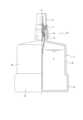
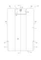
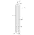
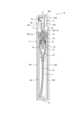
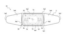
図1は、本発明の第一実施形態に係る、噴出容器1Aの正面図である。本実施形態では、正面側を前側とし、背面側を後側としている。図中、符号Oは、噴出容器1Aの中心軸線(以下、単に、「中心軸線O」ともいう。)である。また、図2は、噴出容器1Aの平面図である。図2において、噴出容器1Aは、上側から示されている。本実施形態では、後述の噴出ヘッド4が配置されている側を上側とし、後述の容器2が配置されている側を下側としている。図3は、噴出容器1Aの側面図である。図3は、図1の右側面である。本実施形態では、噴出容器1Aの左右側面は対称な形状である。図4は、図1のA-A断面図である。本実施形態では、A-A断面は、中心軸線Oを含む断面であって、噴出容器1Aの前後方向に延びている。図5は、図3のB-B断面図である。本実施形態では、B-B断面は、中心軸線Oを含む断面であって、噴出容器1Aの左右方向に延びている。なお、A-A断面及びB-B断面は互いに直交する断面である。 FIG. 1 is a front view of anejection container 1A according to a first embodiment of the present invention. In this embodiment, the front side is the front side, and the back side is the rear side. In the figure, the symbol O is the central axis (hereinafter also simply referred to as "central axis O") of theejection container 1A. Moreover, FIG. 2 is a plan view of theejection container 1A. In FIG. 2, theejection container 1A is shown from above. In this embodiment, the side where theejection head 4 described later is arranged is defined as the upper side, and the side where the below-mentionedcontainer 2 is arranged is defined as the lower side. FIG. 3 is a side view of theejection container 1A. FIG. 3 is a right side view of FIG. In this embodiment, the left and right side surfaces of theejection container 1A have a symmetrical shape. FIG. 4 is a sectional view taken along line AA in FIG. In this embodiment, the AA cross section is a cross section that includes the central axis O, and extends in the front-rear direction of theejection container 1A. FIG. 5 is a sectional view taken along line BB in FIG. In this embodiment, the BB cross section is a cross section that includes the central axis O, and extends in the left-right direction of theejection container 1A. Note that the AA cross section and the BB cross section are cross sections that are perpendicular to each other.

図5を参照すれば、噴出容器1Aは、口部2aを有する容器2を備えている。 Referring to FIG. 5, theejection container 1A includes acontainer 2 having amouth portion 2a.

本実施形態では、容器2は、口部2aと容器本体2bとを有している。図4を参照すれば、本実施形態では、容器2は、容器本体2bの前後方向の厚さが左右方向の幅よりも狭い偏平な容器である。図5を参照すれば、容器2は、左右両側に、2つの側壁2w3を有している。図4を参照すれば、容器2は、前後側に、前壁2w1及び後壁2w2を有している。実施形態において、容器2は、前壁2w1及び後壁2w2の厚さが2つの側壁2w3の幅よりも狭い、偏平な容器である。 In this embodiment, thecontainer 2 has amouth portion 2a and acontainer body 2b. Referring to FIG. 4, in this embodiment, thecontainer 2 is a flat container in which the thickness of the containermain body 2b in the front-rear direction is narrower than the width in the left-right direction. Referring to FIG. 5, thecontainer 2 has two side walls 2w3 on both left and right sides. Referring to FIG. 4, thecontainer 2 has a front wall 2w1 and a rear wall 2w2 on the front and rear sides. In the embodiment, thecontainer 2 is a flat container in which the thickness of the front wall 2w1 and the rear wall 2w2 is narrower than the width of the two side walls 2w3.

また、噴出容器1Aは、容器2の口部2aに配置されたポンプ3を備えている。 Further, theejection container 1A includes apump 3 disposed at themouth portion 2a of thecontainer 2.

図4を参照すれば、本実施形態では、ポンプ3は、容器2に充填された液体Lを吸引するためのチューブ3aと、チューブ3aが下端に接続されたシリンダ3bと、シリンダ3bの上端に取り付けられたポンプカバー3cと、を有している。 Referring to FIG. 4, in this embodiment, thepump 3 includes a tube 3a for sucking the liquid L filled in thecontainer 2, acylinder 3b to which the tube 3a is connected to the lower end, and acylinder 3b to which the tube 3a is connected to the upper end. It has an attachedpump cover 3c.

また、ポンプ3は、吸入弁3dを有している。吸入弁3dは、シリンダ3b内に配置されている。本実施形態では、吸入弁3dは、ボール弁である。ただし、吸入弁3dは、既存の逆止弁を採用することができ、ボール弁に限定されない。 Moreover, thepump 3 has asuction valve 3d. Thesuction valve 3d is arranged within thecylinder 3b. In this embodiment, thesuction valve 3d is a ball valve. However, thesuction valve 3d can be an existing check valve and is not limited to a ball valve.

また、ポンプ3は、第1リターンスプリング3eと、ピストン3fと、を有している。第1リターンスプリング3e及びピストン3fは、シリンダ3b内に配置されている。ピストン3fは、シリンダ3bに対して摺動可能に配置されている。また、ピストン3fは、第1リターンスプリング3eを介してシリンダ3bに対して弾性支持されている。 Thepump 3 also includes afirst return spring 3e and apiston 3f. Thefirst return spring 3e and thepiston 3f are arranged within thecylinder 3b. Thepiston 3f is arranged slidably relative to thecylinder 3b. Further, thepiston 3f is elastically supported by thecylinder 3b via afirst return spring 3e.

また、ポンプ3は、プランジャ3gと、第2リターンスプリング3hと、ステム3iと、を有している。プランジャ3g、第2リターンスプリング3h及びステム3iは、シリンダ3b内に配置されている。プランジャ3gは、ピストン3fを貫通している。第2リターンスプリング3hは、ピストン3fとステム3iとの間に配置されている。第2リターンスプリング3hは、ピストン3fを介してプランジャ3gを下側に押圧する。これにより、プランジャ3gの下端部は、ピストン3fに形成された貫通穴を開閉可能な排出弁として機能する。また、第2リターンスプリング3hは、ステム3iを上側に押圧する。ステム3iの下端部は、ポンプカバー3cによって抜け止めされている。ステム3iの上端部は、ポンプカバー3cを貫通し、当該ポンプカバー3cから上側に突出している。ポンプ3は、第1リターンスプリング3eの付勢力と合せて、ステム3iの上端部を操作することによって動作させることができる。これにより、ポンプ3は、ステム3iを介したピストン2の押込み及び当該押込みの解除を繰り返すことによって、チューブ3aを通して容器2の液体Lをシリンダ3b内に吸引し、当該シリンダ3bからステム3iを通して圧送することができる。 Thepump 3 also includes aplunger 3g, asecond return spring 3h, and astem 3i. Theplunger 3g,second return spring 3h, and stem 3i are arranged within thecylinder 3b. Theplunger 3g passes through thepiston 3f. Thesecond return spring 3h is arranged between thepiston 3f and thestem 3i. Thesecond return spring 3h presses theplunger 3g downward via thepiston 3f. Thereby, the lower end of theplunger 3g functions as a discharge valve that can open and close the through hole formed in thepiston 3f. Further, thesecond return spring 3h presses thestem 3i upward. The lower end of thestem 3i is prevented from coming off by apump cover 3c. The upper end of thestem 3i passes through thepump cover 3c and projects upward from thepump cover 3c. Thepump 3 can be operated by operating the upper end of thestem 3i together with the biasing force of thefirst return spring 3e. Thereby, thepump 3 sucks the liquid L in thecontainer 2 into thecylinder 3b through the tube 3a by repeatedly pushing thepiston 2 through thestem 3i and releasing the push, and pumps the liquid L from thecylinder 3b through thestem 3i. can do.

また、噴出容器1Aは、ポンプ3に取り付けられた噴出ヘッド4を備えている。 Further, theejection container 1A includes anejection head 4 attached to apump 3.

本実施形態では、噴出ヘッド4は、ステム3iの上端部に取り付けられている。噴出ヘッド4の頂壁4w4は、使用者の指によって押圧することができる。これにより、噴出ヘッド4に対する下側への押し下げ及びその解除を繰り返せば、ポンプ3を駆動させることができる。また、噴出ヘッド4は、容器2内の液体Lを噴出させるための噴出口4aを有している。本実施形態では、噴出ヘッド4は、前壁4w1と後壁4w2とを有している。噴出口4aは、前壁4w1に設けられている。噴出口4aは、容器2内の液体Lを外界に噴出させることができる。本実施形態では、噴出ヘッド4は、噴出口4aが形成された噴霧チップ4cを有している。これにより、本実施形態では、噴出口4aを通して、容器2内の液体Lを噴霧させることができる。ただし、噴出ヘッド4は、噴霧チップ4cを省略することができる。この場合、噴出口4aを通して、容器2内の液体Lをそのまま吐出させることができる。 In this embodiment, theejection head 4 is attached to the upper end of thestem 3i. The top wall 4w4 of theejection head 4 can be pressed by a user's finger. As a result, thepump 3 can be driven by repeatedly pressing theejection head 4 downward and releasing it. Further, theejection head 4 has anejection port 4a for ejecting the liquid L in thecontainer 2. In this embodiment, theejection head 4 has a front wall 4w1 and a rear wall 4w2. Thespout 4a is provided on the front wall 4w1. Thespout 4a can jet the liquid L in thecontainer 2 to the outside world. In this embodiment, theejection head 4 has aspray tip 4c in which anejection port 4a is formed. Thereby, in this embodiment, the liquid L in thecontainer 2 can be sprayed through thespout 4a. However, thespray head 4 can omit thespray tip 4c. In this case, the liquid L in thecontainer 2 can be directly discharged through thespout 4a.

また、噴出容器1Aは、カバー5を備えている。カバー5は、容器2を当該容器2の口部2aから挿入可能な挿入口A1と、噴出ヘッド4を露出させる露出口A2とが形成されている。 Moreover, theejection container 1A is equipped with acover 5. Thecover 5 is formed with an insertion opening A1 into which thecontainer 2 can be inserted through themouth 2a of thecontainer 2, and an exposure opening A2 through which theejection head 4 is exposed.

図4を参照すれば、カバー5は、容器2を挿入口A1から挿入する、スロットインタイプのカバーである。容器2は、カバー5の下部に形成された挿入口A1を通して、カバー5の内部に挿入されている。図4に示すように、本実施形態では、容器2及びポンプ3は、カバー5の内部に挿入された状態で、カバー5の前壁5w1及び後壁5W2によって覆われている。また、噴出ヘッド4は、カバー5の上部に形成された露出口A2を通して、カバー5から露出している。本実施形態では、カバー5は、仕切壁5w5を有している。仕切壁5w5は、カバー5の内部を上下に仕切る壁である。本実施形態では、露出口A2は、仕切壁5w5に形成された貫通穴である。 Referring to FIG. 4, thecover 5 is a slot-in type cover into which thecontainer 2 is inserted through the insertion opening A1. Thecontainer 2 is inserted into thecover 5 through an insertion opening A1 formed at the bottom of thecover 5. As shown in FIG. 4, in this embodiment, thecontainer 2 and thepump 3 are inserted into thecover 5 and covered by the front wall 5w1 and the rear wall 5W2 of thecover 5. Further, theejection head 4 is exposed from thecover 5 through an exposure opening A2 formed in the upper part of thecover 5. In this embodiment, thecover 5 has a partition wall 5w5. The partition wall 5w5 is a wall that partitions the inside of thecover 5 into upper and lower parts. In this embodiment, the exposure opening A2 is a through hole formed in the partition wall 5w5.

また、本実施形態では、露出口A2は、カバー5の上側部分に形成された開放空間R5に通じている。図5を参照すれば、本実施形態において、カバー5は、さらに2つの内側側壁5w6を有している。2つの内側側壁5w6は、それぞれ、仕切壁5w5の左右両端に連なるとともに上側に向かって延びている。本実施形態では、開放空間R5は、仕切壁5w5と、2つの内側側壁5w6と、によって形成されている。本実施形態では、開放空間R5は、カバー5の上側部分を前後方向に切り欠いて形成された空間である。 Further, in this embodiment, the exposure opening A2 communicates with an open space R5 formed in the upper part of thecover 5. Referring to FIG. 5, in this embodiment, thecover 5 further includes two inner side walls 5w6. The two inner side walls 5w6 are connected to both left and right ends of the partition wall 5w5 and extend upward. In this embodiment, the open space R5 is formed by a partition wall 5w5 and two inner side walls 5w6. In this embodiment, the open space R5 is a space formed by cutting out the upper part of thecover 5 in the front-rear direction.

また、図5を参照すれば、容器2、ポンプ3及び噴出ヘッド4は、カバー5の外側側壁5w3によって覆われている。外側側壁5w3の上端と内側側壁5w6の上端とは、頂壁5w4によって閉じられている。さらに、本実施形態では、カバー5には、挿入口A1に連なるスリットS5が形成されている。本実施形態では、カバー5は、2つのスリットS5を有している。2つのスリットS5はそれぞれ、左右両側の外側側壁5w3に形成されている。本実施形態では、容器2は、摘み部2dを有している。本実施形態では、摘み部2dは、容器本体2bの左右両側の下端部に形成されている。図5に示すように、本実施形態では、スリットS5は、容器2がカバー5の内部に挿入された状態で、容器2に形成された摘み部2dを収容する。 Moreover, if FIG. 5 is referred, thecontainer 2, thepump 3, and theejection head 4 are covered by the outer side wall 5w3 of thecover 5. The upper end of the outer side wall 5w3 and the upper end of the inner side wall 5w6 are closed by a top wall 5w4. Furthermore, in this embodiment, thecover 5 is formed with a slit S5 that continues to the insertion port A1. In this embodiment, thecover 5 has two slits S5. The two slits S5 are formed in the outer side walls 5w3 on both the left and right sides, respectively. In this embodiment, thecontainer 2 has aknob 2d. In this embodiment, theknobs 2d are formed at the lower end portions on both left and right sides of thecontainer body 2b. As shown in FIG. 5, in this embodiment, the slit S5 accommodates theknob 2d formed on thecontainer 2 when thecontainer 2 is inserted into thecover 5.

さらに、カバー5は、ポンプ3を押さえる押さえ部5aと、容器2の口部2aの外面2fに係止可能な爪5cが設けられた弾性片5dを有している。カバー5は、爪5cの係止及び係止解除によって容器2及びポンプ3に対して着脱可能である。ここで、「係止」とは、容器2の口部2aの外面2fに引っ掛けることを意味する。 Furthermore, thecover 5 has a holdingpart 5a for holding down thepump 3, and anelastic piece 5d provided with aclaw 5c that can be locked to theouter surface 2f of themouth part 2a of thecontainer 2. Thecover 5 can be attached to and detached from thecontainer 2 and thepump 3 by locking and unlocking theclaws 5c. Here, "locking" means hooking on theouter surface 2f of themouth 2a of thecontainer 2.

図5を参照すれば、弾性片5dの上端部5d1は、仕切壁5w5に固定されている。また、弾性片5dは、仕切壁5w5から中心軸線Oに沿って下側に延びている。これによって、弾性片5dは、上端部5d1を起点に変形及び復元が可能である。本実施形態では、爪5cは、弾性片5dの下端部5d2に設けられた内向きの爪である。爪5cは、口部2aの外面2fに形成された凹凸部に係止させることができる。本実施形態では、容器2は、口部2aの外面2fに突起部2cを有している。本実施形態では、爪5cは、突起部2cの下端に係止することができる。 Referring to FIG. 5, the upper end portion 5d1 of theelastic piece 5d is fixed to the partition wall 5w5. Further, theelastic piece 5d extends downward from the partition wall 5w5 along the central axis O. Thereby, theelastic piece 5d can be deformed and restored starting from the upper end portion 5d1. In this embodiment, theclaw 5c is an inward claw provided on the lower end 5d2 of theelastic piece 5d. Theclaw 5c can be engaged with an uneven portion formed on theouter surface 2f of themouth portion 2a. In this embodiment, thecontainer 2 has aprojection 2c on theouter surface 2f of themouth 2a. In this embodiment, theclaw 5c can be locked to the lower end of theprotrusion 2c.

また、本実施形態では、ポンプ3が容器2とともにカバー5に挿入されたとき、カバー5に設けられた押さえ部5aがポンプカバー3cの上端を押さえる。これによって、カバー5は、押さえ部5a及び爪5cによって、容器2とともにポンプ3を強固に固定する。なお、押さえ部5aは、仕切壁5w5と別体に設けることができる。また、押さえ部5aは、仕切壁5w5で構成することができる。 Furthermore, in this embodiment, when thepump 3 is inserted into thecover 5 together with thecontainer 2, thepresser portion 5a provided on thecover 5 presses the upper end of thepump cover 3c. Thereby, thecover 5 firmly fixes thepump 3 together with thecontainer 2 by the holdingportion 5a and theclaw 5c. Note that the holdingportion 5a can be provided separately from the partition wall 5w5. Further, the holdingportion 5a can be formed of a partition wall 5w5.

噴出ヘッド4は、ポンプ3に取り付けられた状態で、弾性片5dよりも外側の、当該弾性片5dと隣接する位置に配置されることによって当該弾性片5dの変形を抑制可能な変形抑制部4bを有している。 Theejection head 4 is attached to thepump 3 and has adeformation suppressing part 4b that can suppress deformation of theelastic piece 5d by being arranged at a position outside theelastic piece 5d and adjacent to theelastic piece 5d. have.

本実施形態では、変形抑制部4bは、噴出ヘッド4から中心軸線Oに沿って下側に延びている。本実施形態では、変形抑制部4bは、噴出ヘッド4の側壁4w3よりも内側に配置されている。本実施形態では、噴出ヘッド4は、2つの側壁4w3を有している。2つの側壁4w3の上端は、前壁4w1及び後壁4w2(例えば、図4参照。)の上端とともに頂壁4w4に固定されている。本実施形態では、噴出ヘッド4は、2つの変形抑制部4bを有し、2つの変形抑制部4bはそれぞれ、頂壁4w4に固定されている。 In this embodiment, thedeformation suppressing portion 4b extends downward from theejection head 4 along the central axis O. In this embodiment, thedeformation suppressing portion 4b is arranged inside the side wall 4w3 of theejection head 4. In this embodiment, theejection head 4 has two side walls 4w3. The upper ends of the two side walls 4w3 are fixed to the top wall 4w4 together with the upper ends of the front wall 4w1 and the rear wall 4w2 (see FIG. 4, for example). In this embodiment, theejection head 4 has twodeformation suppressing parts 4b, and the twodeforming suppressing parts 4b are each fixed to the top wall 4w4.

また、本実施形態では、カバー5は、噴出ヘッド4の変形抑制部4bを貫通させる開口A5を有している。本実施形態では、カバー5は、2つの開口A5を有している。本実施形態では、2つの開口A5は、中心軸線Oを挟んで対向する左右両側の2箇所の位置に設けられている。本実施形態では、開口A5は、カバー5の仕切壁5w5を上下方向に貫通している。本実施形態では、開口A5は、弾性片5dよりも外側の、当該弾性片5dと隣接する位置に形成されている。本実施形態では、弾性片5dの外面5f1は、開口A5の一部を形作っている。 Further, in this embodiment, thecover 5 has an opening A5 through which thedeformation suppressing portion 4b of theejection head 4 passes. In this embodiment, thecover 5 has two openings A5. In this embodiment, the two openings A5 are provided at two positions on both left and right sides facing each other with the central axis O interposed therebetween. In this embodiment, the opening A5 passes through the partition wall 5w5 of thecover 5 in the vertical direction. In this embodiment, the opening A5 is formed at a position outside theelastic piece 5d and adjacent to theelastic piece 5d. In this embodiment, the outer surface 5f1 of theelastic piece 5d forms part of the opening A5.

噴出ヘッド4をポンプ3に取り付けるとき、噴出ヘッド4に設けられた変形抑制部4bは、カバー5に形成された開口A5を通って、弾性片5dよりも外側の、当該弾性片5dと隣接する位置に配置される。これによって、変形抑制部4bは、弾性片5dが外向きに変形するときに、当該弾性片5dの外面5f1と接触することによって、当該弾性片5dの変形を防止する。本実施形態では、カバー5の弾性片5dに設けられた爪5cが容器2の口部2aに設けられた突起部2cに係止された状態で、噴出ヘッド4をポンプ3に取り付けると、噴出ヘッド4の変形抑制部4bは、弾性片5dの外面5f1に隣接する位置に配置される。これによって、弾性片5dが外向きに変形しようすると、当該弾性片5dは、噴出ヘッド4の変形抑制部4bと接触する。したがって、本実施形態では、噴出ヘッド4がポンプ3に取り付けられた状態では、カバー5及び容器2は、一方が他方から分離できないように、互いにロックされた状態に維持される。 When theejection head 4 is attached to thepump 3, thedeformation suppressing part 4b provided in theejection head 4 passes through the opening A5 formed in thecover 5 and adjoins theelastic piece 5d outside of theelastic piece 5d. placed in position. Thereby, when theelastic piece 5d deforms outward, thedeformation suppressing part 4b comes into contact with the outer surface 5f1 of theelastic piece 5d, thereby preventing theelastic piece 5d from deforming. In this embodiment, when theejection head 4 is attached to thepump 3 with theclaw 5c provided on theelastic piece 5d of thecover 5 locked to theprotrusion 2c provided on themouth 2a of thecontainer 2, the ejection Thedeformation suppressing portion 4b of thehead 4 is arranged at a position adjacent to the outer surface 5f1 of theelastic piece 5d. As a result, when theelastic piece 5d tries to deform outward, theelastic piece 5d comes into contact with thedeformation suppressing portion 4b of theejection head 4. Therefore, in this embodiment, when the jettinghead 4 is attached to thepump 3, thecover 5 and thecontainer 2 are kept locked together so that one cannot be separated from the other.

さらに、本実施形態では、カバー5は、変形抑制部4bよりも外側の、当該変形抑制部4bと隣接する位置に配置される壁5eを有している。 Furthermore, in this embodiment, thecover 5 has awall 5e that is disposed at a position outside thedeformation suppressing part 4b and adjacent to thedeformation suppressing part 4b.

本実施形態では、壁5eは、カバー5から中心軸線Oに沿って下側に延びている。本実施形態では、壁5eは、開口A5よりも外側に配置されている。本実施形態では、壁5eの内面5f2は、開口A5の一部を形作っている。 In this embodiment, thewall 5e extends downward from thecover 5 along the central axis O. In this embodiment, thewall 5e is arranged outside the opening A5. In this embodiment, the inner surface 5f2 of thewall 5e forms part of the opening A5.

噴出ヘッド4をポンプ3に取り付けるとき、噴出ヘッド4に設けられた変形抑制部4bは、カバー5に形成された開口A5を通って、壁5eよりも内側の、当該壁5eと隣接する位置に配置される。これによって、変形抑制部4bが弾性片5dとともに外向きに変形するときに、変形抑制部4bは、壁5eの内面5f2と接触することによって、当該変形抑制部4bの変形を防止する。本実施形態では、カバー5の弾性片5dに設けられた爪5cが容器2の口部2aに設けられた突起部2cに係止された状態で、噴出ヘッド4をポンプ3に取り付けると、噴出ヘッド4の変形抑制部4bは、壁5eの内面5f2に隣接する位置に配置される。これによって、弾性片5dが変形抑制部4bとともに外向きに変形しようすると、噴出ヘッド4に設けられた変形抑制部4bは、カバー5に設けられた壁5eの内面5f2と接触する。したがって、本実施形態では、噴出ヘッド4がポンプ3に取り付けられた状態では、カバー5及び容器2は、互いにより強固にロックされた状態に維持される。 When attaching theejection head 4 to thepump 3, thedeformation suppressing portion 4b provided on theejection head 4 passes through the opening A5 formed in thecover 5 and is located inside thewall 5e at a position adjacent to thewall 5e. Placed. Thereby, when thedeformation suppressing part 4b deforms outward together with theelastic piece 5d, thedeformation suppressing part 4b comes into contact with the inner surface 5f2 of thewall 5e, thereby preventing thedeformation suppressing part 4b from deforming. In this embodiment, when theejection head 4 is attached to thepump 3 with theclaw 5c provided on theelastic piece 5d of thecover 5 locked to theprotrusion 2c provided on themouth 2a of thecontainer 2, the ejection Thedeformation suppressing portion 4b of thehead 4 is arranged at a position adjacent to the inner surface 5f2 of thewall 5e. As a result, when theelastic piece 5d tries to deform outward together with thedeformation suppressing part 4b, thedeformation suppressing part 4b provided on theejection head 4 comes into contact with the inner surface 5f2 of thewall 5e provided on thecover 5. Therefore, in this embodiment, when theejection head 4 is attached to thepump 3, thecover 5 and thecontainer 2 are maintained more firmly locked together.

噴出容器1Aにおいて、変形抑制部4bと弾性片5dとの接触は、噴出ヘッド4の取り外しによって、解除される。 In theejection container 1A, the contact between thedeformation suppressing portion 4b and theelastic piece 5d is released by removing theejection head 4.

本実施形態では、噴出ヘッド4とカバー5とは、変形抑制部4bと弾性片5dとの接触は、噴出ヘッド4のポンプ3に対する取り外しによって、解除されるように構成されている。本実施形態では、カバー5に形成された開口A5の位置は、噴出ヘッド4をポンプ3に取り付けたとき、噴出ヘッド4の変形抑制部4bがカバー5に設けた弾性片5dに隣接した位置になるように構成されている。また、本実施形態では、噴出ヘッド4の変形抑制部4bは、表面に凹凸の無い平滑な面によって形成されている。これによって、噴出ヘッド4をポンプ3に取り付けるときには、変形抑制部4bは、容易に開口A5を通して挿入することができ、また、噴出ヘッド4をポンプ3から取り外すときには、変形抑制部4bは、容易に開口A5を通して引き抜くことができる。 In this embodiment, theejection head 4 and thecover 5 are configured such that the contact between thedeformation suppressing portion 4b and theelastic piece 5d is released when theejection head 4 is removed from thepump 3. In this embodiment, the opening A5 formed in thecover 5 is located at a position where thedeformation suppressing portion 4b of theejection head 4 is adjacent to theelastic piece 5d provided on thecover 5 when theejection head 4 is attached to thepump 3. It is configured to be. Further, in this embodiment, thedeformation suppressing portion 4b of theejection head 4 is formed of a smooth surface with no irregularities on the surface. Thereby, when attaching theejection head 4 to thepump 3, thedeformation suppressing part 4b can be easily inserted through the opening A5, and when removing theejection head 4 from thepump 3, thedeformation suppressing part 4b can be easily inserted. It can be pulled out through opening A5.

次に、図6~図8を参照して、詰め替え用品としての、噴出容器1Aの機能について、説明する。 Next, the function of thesquirt container 1A as a refill product will be explained with reference to FIGS. 6 to 8.

容器2に液体Lを充填するときは、まず、図6に示すように、噴出ヘッド4をポンプ3から取り外す。本実施形態では、一方の手でカバー5を持ったまま、他方の手で噴出ヘッド4を上側に引っ張る。噴出ヘッド4は、図6の矢印に示すように、ポンプ3から引き上げるだけで、当該ポンプ3から取り外すことができる。 When filling thecontainer 2 with the liquid L, first, theejection head 4 is removed from thepump 3, as shown in FIG. In this embodiment, while holding thecover 5 with one hand, theejection head 4 is pulled upward with the other hand. Theejection head 4 can be removed from thepump 3 by simply pulling it up from thepump 3 as shown by the arrow in FIG.

次いで、図7に示すように、カバー5を取り外す。本実施形態では、一方の手で容器2の摘み部2dを摘まんだまま、他方の手でカバー5を上側に引っ張る。噴出ヘッド4を取り外すと、カバー5に設けられた弾性片5dは、左右外側に向かって自由に変形させることができる。このため、カバー5に設けられた弾性片5dの爪5cと、容器2の口部2aに設けられた突起部2cとの係止状態は容易に解除することができる。カバー5は、図7の矢印に示すように、容器2から引き上げるだけで、容器2から取り外すことができる。 Next, as shown in FIG. 7, thecover 5 is removed. In this embodiment, while holding theknob 2d of thecontainer 2 with one hand, thecover 5 is pulled upward with the other hand. When theejection head 4 is removed, theelastic pieces 5d provided on thecover 5 can be freely deformed outward to the left and right. Therefore, the locked state between theclaw 5c of theelastic piece 5d provided on thecover 5 and theprotrusion 2c provided on themouth 2a of thecontainer 2 can be easily released. Thecover 5 can be removed from thecontainer 2 by simply pulling it up from thecontainer 2, as shown by the arrow in FIG.

本実施形態では、最後に、図8に示すように、ポンプ3を取り外す。本実施形態では、一方の手で容器2を持ったまま、他方の手でポンプ3を上側に引っ張る。本実施形態では、ポンプ3は、容器2の口部2aの上端に載せ置かれた状態で嵌合配置されている。このため、ポンプ3は、容器2から引き上げるだけで、図8に示すように、容器2から取り外すことができる。容器2は、容器2と異なる他の、詰め替え用容器(例えば、パウチ容器、注入ボトル)などを用いて、液体Lを充填することができる、詰め替え容器として使用することができる。この場合、容器2は、噴出容器1Aとして流通させることができる。この場合、噴出容器1Aのレフィルは、前記詰め替え用容器に充填された液体Lを、容器2の口部2aを通して容器本体2b内に再充填することによって行うことができる。 In this embodiment, finally, as shown in FIG. 8, thepump 3 is removed. In this embodiment, while holding thecontainer 2 with one hand, thepump 3 is pulled upward with the other hand. In this embodiment, thepump 3 is placed and fitted onto the upper end of themouth 2a of thecontainer 2. Therefore, thepump 3 can be removed from thecontainer 2 by simply pulling it up from thecontainer 2, as shown in FIG. Thecontainer 2 can be used as a refillable container that can be filled with the liquid L using a refillable container other than the container 2 (for example, a pouch container, an injection bottle), or the like. In this case, thecontainer 2 can be distributed as theejection container 1A. In this case, theejection container 1A can be refilled by refilling thecontainer body 2b with the liquid L filled in the refill container through themouth 2a of thecontainer 2.

また、容器2は、予め液体Lが充填されている付け替え容器として使用することができる。この場合、容器2は、口部2aがキャップによって封止された状態の付け替え容器として流通させることができる。なお、図9は、噴出容器1Aに付け替えるための付け替え容器20としての、ポンプ3及び容器2の一例を示す。付け替え容器20は、容器2の口部2aにポンプ3を取り付けている。なお、符号21は、容器2の口部2aに対して着脱可能なキャップである。この例では、容器2及びポンプ3は、キャップ21によって一体に組付けられている。この場合、噴出容器1Aのレフィルは、付け替え容器20からキャップ21を取り外した後、カバー5、噴出ヘッド4の順で取り付けを行うことによって、液体Lを再充填することができる。 Moreover, thecontainer 2 can be used as a replacement container filled with the liquid L in advance. In this case, thecontainer 2 can be distributed as a replacement container with themouth portion 2a sealed with a cap. In addition, FIG. 9 shows an example of thepump 3 and thecontainer 2 as areplacement container 20 for replacing with theejection container 1A. Thereplacement container 20 has apump 3 attached to themouth 2a of thecontainer 2. In addition, the code|symbol 21 is a cap removably attached to themouth part 2a of thecontainer 2. In this example, thecontainer 2 and thepump 3 are assembled together by acap 21. In this case, theejection container 1A can be refilled with the liquid L by removing thecap 21 from thereplacement container 20 and then attaching thecover 5 and theejection head 4 in this order.

次いで、本発明の第二実施形態に係る、噴出容器1Bについて説明をする。なお、以下の説明において、噴出容器1Aと実質的に同一の部分は、同一の符号をもって、その説明を省略する。 Next, theejection container 1B according to the second embodiment of the present invention will be explained. In addition, in the following description, the substantially the same part as 1 A of ejection containers has the same code|symbol, and the description is abbreviate|omitted.

図10は、本発明の第二実施形態に係る、噴出容器1Bの正面図である。図11は、噴出容器1Bの平面図である。図12は、噴出容器1Bの側面図である。図13は、図10のA-A断面図である。図14は、図12のB-B断面図である。 FIG. 10 is a front view of theejection container 1B according to the second embodiment of the present invention. FIG. 11 is a plan view of theejection container 1B. FIG. 12 is a side view of theejection container 1B. FIG. 13 is a sectional view taken along line AA in FIG. FIG. 14 is a sectional view taken along line BB in FIG. 12.

本実施形態では、変形抑制部4bと弾性片5dの外面5f1との接触は、噴出ヘッド4の回転によって、解除される。図15は、噴出容器1Bにおいて、噴出ヘッド4を回転させた状態を、図12のB-B断面相当で示す断面図である。本実施形態では、噴出ヘッド4を中心軸線Oの周りに回転させると、図15に示すように、噴出ヘッド4に設けられた変形抑制部4bは、カバー5に設けられた弾性片5dからずれた位置に移動する。これによって、カバー5に設けられた弾性片5dは、左右外側に向かって自由に変形させることができる。 In this embodiment, the contact between thedeformation suppressing portion 4b and the outer surface 5f1 of theelastic piece 5d is released by rotation of theejection head 4. FIG. 15 is a cross-sectional view corresponding to the BB section in FIG. 12, showing a state in which theejection head 4 is rotated in theejection container 1B. In this embodiment, when theejection head 4 is rotated around the central axis O, thedeformation suppressing portion 4b provided on theejection head 4 is displaced from theelastic piece 5d provided on thecover 5, as shown in FIG. move to the specified position. Thereby, theelastic pieces 5d provided on thecover 5 can be freely deformed toward the left and right sides.

本実施形態では、噴出ヘッド4とカバー5とは、変形抑制部4bと弾性片5dとの接触は、噴出ヘッド4のポンプ3に対する当該ポンプ3の軸線周りの回転によって、解除されるように構成されている。本実施形態では、噴出ヘッド4の変形抑制部4bは、噴出容器1Aと同様、表面に凹凸の無い平滑な面によって形成されている。これによって、噴出ヘッド4をポンプ3に取り付けるときには、変形抑制部4bは、容易に開口A5を通して挿入することができ、また、噴出ヘッド4をポンプ3から取り外すときには、変形抑制部4bは、容易に開口A5を通して引き抜くことができる。 In this embodiment, theejection head 4 and thecover 5 are configured such that the contact between thedeformation suppressing portion 4b and theelastic piece 5d is released by rotation of theejection head 4 with respect to thepump 3 around the axis of thepump 3. has been done. In this embodiment, thedeformation suppressing portion 4b of theejection head 4 is formed of a smooth surface with no irregularities, similar to theejection container 1A. Thereby, when attaching theejection head 4 to thepump 3, thedeformation suppressing part 4b can be easily inserted through the opening A5, and when removing theejection head 4 from thepump 3, thedeformation suppressing part 4b can be easily inserted. It can be pulled out through opening A5.

また、本実施形態では、カバー5に形成された開口A5の位置は、噴出容器1Aと同様、噴出ヘッド4をポンプ3に取り付けたとき、噴出ヘッド4の変形抑制部4bがカバー5に設けた弾性片5dに隣接した位置になるように構成されている。 In addition, in this embodiment, the position of the opening A5 formed in thecover 5 is such that when theejection head 4 is attached to thepump 3, thedeformation suppressing part 4b of theejection head 4 is provided in thecover 5, as in the case of theejection container 1A. It is configured to be located adjacent to theelastic piece 5d.

図16Aは、図11の平面図であって、噴出ヘッド4のみを透視図として示す平面図である。また、図16Bは、図16Aの噴出ヘッド4を回転させた状態を示す図である。図17Aは、図16Aの状態を、図14のC-C断面相当で示す断面図である。図17Bは、図16Bの状態を、図15のD-D断面相当で示す断面図である。 FIG. 16A is a plan view of FIG. 11, showing only theejection head 4 as a perspective view. Moreover, FIG. 16B is a diagram showing a state in which theejection head 4 of FIG. 16A is rotated. FIG. 17A is a sectional view corresponding to the CC section in FIG. 14, showing the state in FIG. 16A. FIG. 17B is a sectional view corresponding to the DD section in FIG. 15, showing the state in FIG. 16B.

図17Aを参照すれば、カバー5に形成された開口A5は、中心軸線Oの周りに延びている。また、本実施形態では、開口A5の中心軸線Oの周りの幅W5(以下、「開口A5の周方向幅W5」ともいう。)は、図17Aに示すように、変形抑制部4bの中心軸線Oの周りの幅W4(以下、「変形抑制部4bの周方向幅W4」ともいう。)よりも広く設定されている。これによって、噴出ヘッド4を回転させると、図17Bに示すように、変形抑制部4bは、カバー5に設けられた弾性片5dからずれた位置に移動する。これによって、カバー5に設けられた弾性片5dは、左右外側に向かって自由に変形させることができる。 Referring to FIG. 17A, an opening A5 formed in thecover 5 extends around the central axis O. In addition, in the present embodiment, the width W5 around the central axis O of the opening A5 (hereinafter also referred to as "circumferential width W5 of the opening A5") is the central axis of thedeformation suppressing portion 4b, as shown in FIG. 17A. It is set wider than the width W4 around O (hereinafter also referred to as "circumferential width W4 of thedeformation suppressing portion 4b"). As a result, when theejection head 4 is rotated, thedeformation suppressing portion 4b moves to a position displaced from theelastic piece 5d provided on thecover 5, as shown in FIG. 17B. Thereby, theelastic pieces 5d provided on thecover 5 can be freely deformed toward the left and right sides.

本実施形態では、仕切壁5w5には、噴出ヘッド4に設けられた変形抑制部4bの移動を制限するためのストッパ突起5pが設けられている。本実施形態では、ストッパ突起5pは、カバー5の押さえ部5aの外面に設けられている。本実施形態では、弾性片5dの上端部は、押さえ部5aの外面に設けられている。言い換えれば、ストッパ突起5pは、弾性片5dの外面に設けることもできる。本実施形態では、カバー5は、2つの弾性片5dのそれぞれに、2組のストッパ突起5pを有している。2組のストッパ突起5pは、それぞれ、噴出ヘッド4に設けられた1つの変形抑制部4bが、対応する1つの弾性片5dの爪5cと隣接する位置で位置決めされるように設けられている。本実施形態では、ストッパ突起5pは、弾性片5dの外面を、当該弾性片5dの上端から下端まで延びている。ただし、本発明によれば。ストッパ突起5pは、爪5cが設けられた弾性片5dの下端部に設けられていればよい。 In this embodiment, the partition wall 5w5 is provided with astopper protrusion 5p for restricting the movement of thedeformation suppressing portion 4b provided in theejection head 4. In this embodiment, thestopper protrusion 5p is provided on the outer surface of thepressing portion 5a of thecover 5. In this embodiment, the upper end portion of theelastic piece 5d is provided on the outer surface of the holdingportion 5a. In other words, thestopper protrusion 5p can also be provided on the outer surface of theelastic piece 5d. In this embodiment, thecover 5 has two sets ofstopper protrusions 5p on each of the twoelastic pieces 5d. The two sets ofstopper protrusions 5p are provided such that onedeformation suppressing portion 4b provided on theejection head 4 is positioned adjacent to theclaw 5c of the corresponding oneelastic piece 5d. In this embodiment, thestopper protrusion 5p extends on the outer surface of theelastic piece 5d from the upper end to the lower end of theelastic piece 5d. However, according to the present invention. Thestopper protrusion 5p may be provided at the lower end of theelastic piece 5d provided with theclaw 5c.

次に、付け替え用品としての、噴出容器1Bの機能について、説明する。 Next, the function of theejection container 1B as a replacement product will be explained.

まず、容器2に液体を充填するときは、まず、図16Aに示す状態から、噴出ヘッド4をポンプ3に対して中心軸線Oの周りに回転させる。本実施形態では、一方の手でカバー5を持ったまま、他方の手で、図16Bの矢印に示すように、噴出ヘッド4を回転させる。これによって、噴出ヘッド4に設けられた変形抑制部4bは、カバー5に設けられたストッパ突起5pを乗り越えることで、図17Aに示す位置から、図17Bに示す位置に移動する。これによって、図17Bに示すように、噴出ヘッド4に設けられた変形抑制部4bは、カバー5に設けられた弾性片5dからずれた位置に移動する。したがって、カバー5に設けられた弾性片5dは、左右外側に向かって自由に変形させることができる。 First, when filling thecontainer 2 with liquid, theejection head 4 is first rotated around the central axis O relative to thepump 3 from the state shown in FIG. 16A. In this embodiment, while holding thecover 5 with one hand, theejection head 4 is rotated with the other hand as shown by the arrow in FIG. 16B. As a result, thedeformation suppressing portion 4b provided on theejection head 4 moves over thestopper protrusion 5p provided on thecover 5 from the position shown in FIG. 17A to the position shown in FIG. 17B. As a result, as shown in FIG. 17B, thedeformation suppressing portion 4b provided on theejection head 4 moves to a position displaced from theelastic piece 5d provided on thecover 5. Therefore, theelastic pieces 5d provided on thecover 5 can be freely deformed toward the left and right sides.

次いで、噴出容器1Aと同様、噴出ヘッド4をポンプ3から取り外す。本実施形態では、噴出容器1Aと同様、一方の手でカバー5を持ったまま、他方の手で噴出ヘッド4を上側に引っ張る。噴出ヘッド4は、噴出容器1Aと同様、ポンプ3から引き上げるだけで、当該ポンプ3から取り外すことができる。 Next, theejection head 4 is removed from thepump 3 in the same way as theejection container 1A. In this embodiment, similarly to theejection container 1A, while holding thecover 5 with one hand, theejection head 4 is pulled upward with the other hand. Theejection head 4, like theejection container 1A, can be removed from thepump 3 by simply pulling it up from thepump 3.

次いで、図18に示すように、カバー5を取り外す。本実施形態では、噴出容器1Aと同様、一方の手で容器2の摘み部2dを摘まんだまま、他方の手でカバー5を上側に引っ張る。噴出ヘッド4を取り外すと、カバー5に設けられた弾性片5dは、左右外側に向かって自由に変形させることができる。このため、カバー5に設けられた弾性片5dの爪5cと、容器2の口部2aに設けられた突起部2cとの係止状態は、噴出容器1Aと同様、容易に解除することができる。カバー5は、噴出容器1Aと同様、図18の矢印に示すように、容器2から引き上げるだけで、容器2から取り外すことができる。 Next, as shown in FIG. 18, thecover 5 is removed. In this embodiment, similarly to theejection container 1A, while holding theknob 2d of thecontainer 2 with one hand, thecover 5 is pulled upward with the other hand. When theejection head 4 is removed, theelastic pieces 5d provided on thecover 5 can be freely deformed outward to the left and right. Therefore, the locked state between theclaw 5c of theelastic piece 5d provided on thecover 5 and theprotrusion 2c provided on themouth 2a of thecontainer 2 can be easily released as in the case of the spoutingcontainer 1A. . Like theejection container 1A, thecover 5 can be removed from thecontainer 2 by simply pulling it up from thecontainer 2 as shown by the arrow in FIG.

例えば、図9の付け替え容器20を使用して、噴出容器1Bのレフィルを行おうとする場合、本実施形態では、付け替え容器20からキャップ21を取り外し、容器2に対してカバー5を取り付けたのち、ポンプ3に噴出ヘッド4を取り付ける。この場合、噴出ヘッド4は、図16Aのように、平面視において、前壁4w1(噴出口4a)が正面を向くように、取り付けることができる。これによって、噴出容器1Bの付け替えが完了する。また、この場合、噴出ヘッド4は、図16Bのように、平面視において、前壁4w1(噴出口4a)が正面に対して斜めを向くように、取り付けることができる。ただし、図16Bのように取り付ける場合には、噴出ヘッド4を図16Aの位置まで回転させ、前壁4w1(噴出口4a)が正面を向くようにする。これによって、噴出容器1Bの付け替えが完了する。 For example, when trying to refill theejection container 1B using thereplacement container 20 of FIG. 9, in this embodiment, after removing thecap 21 from thereplacement container 20 and attaching thecover 5 to thecontainer 2, Attach theejection head 4 to thepump 3. In this case, theejection head 4 can be attached so that the front wall 4w1 (theejection port 4a) faces the front in plan view, as shown in FIG. 16A. This completes the replacement of theejection container 1B. Moreover, in this case, theejection head 4 can be attached so that the front wall 4w1 (theejection port 4a) faces diagonally with respect to the front in plan view, as shown in FIG. 16B. However, when installing as shown in FIG. 16B, theejection head 4 is rotated to the position shown in FIG. 16A so that the front wall 4w1 (theejection port 4a) faces the front. This completes the replacement of theejection container 1B.

なお、本実施形態では、噴出容器1Aで説明したのと同様、最後に、図8に示すように、ポンプ3を取り外すこともできる。この場合、容器2は、噴出容器1Aと同様、例えば、前記詰め替え用容器を用いて、容器2の中に液体を充填することができる、 In addition, in this embodiment, thepump 3 can also be removed at the end, as shown in FIG. 8, as described with respect to theejection container 1A. In this case, thecontainer 2 can be filled with liquid, for example, using the refill container, similar to theejection container 1A.

上述のとおり、本発明によれば、変形抑制部4bと弾性片5dとの接触は、噴出ヘッド4の取り外しによって、または、噴出ヘッド4の回転によって、解除される。したがって、本発明によれば、噴出ヘッド4を操作片として用いることにより、容器2を着脱させることができる、新規の噴出容器を提供することができる。 As described above, according to the present invention, the contact between thedeformation suppressing portion 4b and theelastic piece 5d is released by removing theejection head 4 or by rotating theejection head 4. Therefore, according to the present invention, it is possible to provide a novel ejection container in which thecontainer 2 can be attached and detached by using theejection head 4 as an operation piece.

また、上述の各実施形態において、カバー5は、変形抑制部4bよりも外側の、当該変形抑制部4bと隣接する位置に配置される壁5eを有している。この場合、カバー5及び容器2は、互いにより強固にロックされた状態に維持される。 Further, in each of the above-described embodiments, thecover 5 includes awall 5e that is located outside thedeformation suppressing portion 4b and adjacent to thedeformation suppressing portion 4b. In this case, thecover 5 and thecontainer 2 are kept more firmly locked together.

また、上述の各実施形態において、容器2は、口部2aの外面2fに、爪5cを係止可能な突起部2cを有している。この場合、カバー5及び容器2は、互いにより強固に係止することができる。 Moreover, in each of the above-mentioned embodiments, thecontainer 2 has aprotrusion 2c on theouter surface 2f of themouth 2a to which aclaw 5c can be engaged. In this case, thecover 5 and thecontainer 2 can be more firmly locked to each other.

また、図12を参照すれば、噴出容器1Bにおいて、噴出ヘッド4の側面は、平面視において、円弧形状である。本実施形態では、噴出ヘッド4の側壁4w3は、曲率半径rの円弧形状である。この場合、噴出ヘッド4をカバー5の内側側壁5w6に接触することなく、コンパクトに回転させることができる。 Moreover, if FIG. 12 is referred, in theejection container 1B, the side surface of theejection head 4 is circular arc shape in planar view. In this embodiment, the side wall 4w3 of theejection head 4 has an arc shape with a radius of curvature r. In this case, theejection head 4 can be rotated compactly without contacting the inner side wall 5w6 of thecover 5.

また、噴出容器1A及び1Bは、いわゆる、カード型スプレーと呼ばれる噴出容器である。上述の各実施形態において、容器2及びカバー5は、偏平な形状である。上述の各実施形態において、容器2は、前壁2w1及び後壁2w2の厚さが2つの側壁2w3の幅よりも狭い。また、上述の各実施形態においてカバー5は、前壁5w1及び後壁5w2の厚さが2つの外側側壁5w3の幅よりも狭い。このように、本発明によれば、噴出ヘッド4を操作片として用いることにより、カード型スプレーにレフィル機能を持たせることができる。 Moreover, theejection containers 1A and 1B are ejection containers called so-called card-type spray containers. In each of the embodiments described above, thecontainer 2 and thecover 5 have a flat shape. In each of the embodiments described above, in thecontainer 2, the thickness of the front wall 2w1 and the rear wall 2w2 is narrower than the width of the two side walls 2w3. Further, in each of the above-described embodiments, the thickness of the front wall 5w1 and the rear wall 5w2 of thecover 5 is narrower than the width of the two outer side walls 5w3. As described above, according to the present invention, by using theejection head 4 as an operation piece, a card-type sprayer can be provided with a refill function.

上述したところは、本発明の例示的な実施形態を説明したものであり、特許請求の範囲を逸脱しない範囲で様々な変更を行うことができる。上述した本実施形態および例示的な構成に採用された様々な構成は、適宜、相互に置き換えることができ、又は、組み合わせることができる。 What has been described above describes exemplary embodiments of the invention, and various modifications may be made without departing from the scope of the claims. The various configurations adopted in the present embodiment and the exemplary configurations described above can be replaced with each other or combined as appropriate.

例えば、図2を参照すれば、噴出容器1Aにおいて、噴出ヘッド4は、平面視において、左右方向の幅が広い矩形である。また、カバー5に形成された開放空間R5も左右方向の幅が広い矩形である。この場合、図2に示すように、噴出ヘッド4は、カバー5の内側側壁5w6を案内にして、噴出ヘッド4を容易に着脱させることができる。また、噴出容器1Aの場合、例えば、図1、図6を参照すれば、カバー5の前壁5w1及び後壁5w2の少なくともいずれか一方を開放空間R5に延長させることができる。本実施形態では、例えば、図1、図6に示すように、カバー5の前壁5w1及び後壁5w2の縁部e5は、噴出ヘッド4の前壁4w1及び後壁4w2の下端部を覆うように、開放空間R5の一部まで延長されている。 For example, referring to FIG. 2, in theejection container 1A, theejection head 4 has a rectangular shape with a wide width in the left-right direction when viewed from above. Further, the open space R5 formed in thecover 5 is also rectangular with a wide width in the left-right direction. In this case, as shown in FIG. 2, theejection head 4 can be easily attached and detached using the inner side wall 5w6 of thecover 5 as a guide. In the case of theejection container 1A, for example, referring to FIGS. 1 and 6, at least one of the front wall 5w1 and the rear wall 5w2 of thecover 5 can be extended into the open space R5. In this embodiment, for example, as shown in FIGS. 1 and 6, the edge e5 of the front wall 5w1 and the rear wall 5w2 of thecover 5 is configured to cover the lower ends of the front wall 4w1 and the rear wall 4w2 of theejection head 4. In addition, it extends to a part of the open space R5.

1A,1B:噴出容器, 2:容器, 2a:容器の口部, 2c:突起部, 3:ポンプ, 4:噴出ヘッド, 4b:変形抑制部, 4w3:噴出ヘッドの側壁, 5:カバー, 5a:押さえ部, 5c爪, 5d:弾性片, 5e:壁, A1;挿入口, A2:露出口, O:噴出容器の中心軸線
1A, 1B: Ejection container, 2: Container, 2a: Container mouth, 2c: Projection, 3: Pump, 4: Ejection head, 4b: Deformation suppressing part, 4w3: Side wall of ejection head, 5: Cover, 5a : Holding part, 5c claw, 5d: Elastic piece, 5e: Wall, A1: Insertion port, A2: Exposure port, O: Center axis of ejection container

Claims (5)

Translated fromJapanese
口部を有する容器と、
前記容器の前記口部に配置されたポンプと、
前記ポンプに取り付けられた噴出ヘッドと、
前記容器を当該容器の口部から挿入可能な挿入口と、前記噴出ヘッドを露出させる露出口とが形成されているカバーと、を備え、
前記カバーは、前記ポンプを押さえる押さえ部と、前記容器の前記口部の外面に係止可能な爪が設けられた弾性片を有しており、前記爪の係止及び係止解除によって前記容器及び前記ポンプに対して着脱可能であり、
前記噴出ヘッドは、前記ポンプに取り付けられた状態で、前記弾性片よりも外側の、当該弾性片と隣接する位置に配置されることによって当該弾性片の変形を抑制可能な変形抑制部を有しており、
前記変形抑制部と前記弾性片との接触は、前記噴出ヘッドの取り外しによって、または、前記噴出ヘッドの回転によって、解除される、噴出容器。
a container having a mouth;
a pump disposed at the mouth of the container;
a jetting head attached to the pump;
comprising an insertion port through which the container can be inserted through the mouth of the container, and an exposure port that exposes the ejection head;
The cover has a holding part that presses down the pump, and an elastic piece that is provided with a claw that can be locked on the outer surface of the mouth of the container, and when the claw locks and releases the lock, the container is closed. and detachable from the pump,
The ejection head has a deformation suppressing part that is arranged at a position outside the elastic piece and adjacent to the elastic piece when attached to the pump, thereby suppressing deformation of the elastic piece. and
In the ejection container, the contact between the deformation suppressing portion and the elastic piece is released by removing the ejection head or rotating the ejection head.
前記カバーは、前記変形抑制部よりも外側の、当該変形抑制部と隣接する位置に配置される壁を有している、請求項1に記載された噴出容器。 The ejection container according to claim 1, wherein the cover has a wall disposed at a position outside the deformation suppressing part and adjacent to the deformation suppressing part. 前記容器は、前記口部の外面に、前記爪を係止可能な突起部を有している、請求項1又は2に記載された噴出容器。 3. The squirt container according to claim 1, wherein the container has a protrusion on the outer surface of the mouth portion, into which the claw can be engaged. 前記変形抑制部と前記弾性片との接触が前記噴出ヘッドの回転によって解除される噴出容器において、前記噴出ヘッドの側面は、平面視において、円弧形状である、請求項1~3のいずれか1項に記載された噴出容器。 In the ejection container in which contact between the deformation suppressing portion and the elastic piece is released by rotation of the ejection head, a side surface of the ejection head is arcuate in plan view. Squirting containers as described in Section. 前記容器及び前記カバーは、偏平な形状である、請求項1~4のいずれか1項に記載された噴出容器。
The ejection container according to any one of claims 1 to 4, wherein the container and the cover have a flat shape.
JP2020113617A2020-06-302020-06-30 squirt containerActiveJP7345996B2 (en)

Priority Applications (1)

Application NumberPriority DateFiling DateTitle
JP2020113617AJP7345996B2 (en)2020-06-302020-06-30 squirt container

Applications Claiming Priority (1)

Application NumberPriority DateFiling DateTitle
JP2020113617AJP7345996B2 (en)2020-06-302020-06-30 squirt container

Publications (2)

Publication NumberPublication Date
JP2022012075A JP2022012075A (en)2022-01-17
JP7345996B2true JP7345996B2 (en)2023-09-19

Family

ID=80148490

Family Applications (1)

Application NumberTitlePriority DateFiling Date
JP2020113617AActiveJP7345996B2 (en)2020-06-302020-06-30 squirt container

Country Status (1)

CountryLink
JP (1)JP7345996B2 (en)

Families Citing this family (1)

* Cited by examiner, † Cited by third party
Publication numberPriority datePublication dateAssigneeTitle
EP4471935A1 (en)2022-01-282024-12-04Agc Inc.Method for producing sulfide-based solid electrolyte

Citations (2)

* Cited by examiner, † Cited by third party
Publication numberPriority datePublication dateAssigneeTitle
US6053363A (en)1998-02-242000-04-25L'orealPackaging and dispensing assembly for a cosmetic, pharmaceutical or dermo-pharmaceutical product
JP2008247448A (en)2007-03-302008-10-16Yoshino Kogyosho Co LtdLiquid spray

Family Cites Families (2)

* Cited by examiner, † Cited by third party
Publication numberPriority datePublication dateAssigneeTitle
JPH1135069A (en)*1997-07-141999-02-09Sumitomo Bakelite Co LtdContent discharge packaging body
JP4187951B2 (en)*2001-07-302008-11-26株式会社吉野工業所 Discharge container

Patent Citations (2)

* Cited by examiner, † Cited by third party
Publication numberPriority datePublication dateAssigneeTitle
US6053363A (en)1998-02-242000-04-25L'orealPackaging and dispensing assembly for a cosmetic, pharmaceutical or dermo-pharmaceutical product
JP2008247448A (en)2007-03-302008-10-16Yoshino Kogyosho Co LtdLiquid spray

Also Published As

Publication numberPublication date
JP2022012075A (en)2022-01-17

Similar Documents

PublicationPublication DateTitle
JP4863175B2 (en) Aerosol sprayer head cap
JP3916998B2 (en) Trigger type fluid dispenser
CN100346881C (en)Child-resistant trigger sprayer
JP2857032B2 (en) Manual trigger type dispenser and its nozzle
US6669061B2 (en)Pump dispenser and spraying apparatus
WO1999056886A1 (en)Trigger type liquid injector
JP7345996B2 (en) squirt container
JP7291540B2 (en) nasal sprayer
JP2001301853A (en)Jet device for aerosol container
JP6117057B2 (en) Trigger type liquid ejector
JP4757055B2 (en) Attachment for aerosol cans
JP5530224B2 (en) Cap for aerosol container
JP5611673B2 (en) Bubble jet
JP2001354256A (en) Spouting vessel
JP4863289B2 (en) Liquid ejector
JP6193654B2 (en) Button cap integrated with aerosol container
JP7246279B2 (en) trigger type liquid ejector
JP5002377B2 (en) Trigger type liquid ejector
JP2018043777A (en)Jetting device
JP2001287763A (en) Pump dispenser
JP2004122123A (en) Auxiliary cover for pump dispenser and container with pump dispenser
JP2018144831A (en) Trigger type spray mechanism
JPH08230925A (en)Liquid jet container
JP4775793B2 (en) Manual push pump nozzle head
JP7580339B2 (en) Locking member

Legal Events

DateCodeTitleDescription
A621Written request for application examination

Free format text:JAPANESE INTERMEDIATE CODE: A621

Effective date:20230106

A977Report on retrieval

Free format text:JAPANESE INTERMEDIATE CODE: A971007

Effective date:20230821

TRDDDecision of grant or rejection written
A01Written decision to grant a patent or to grant a registration (utility model)

Free format text:JAPANESE INTERMEDIATE CODE: A01

Effective date:20230905

A61First payment of annual fees (during grant procedure)

Free format text:JAPANESE INTERMEDIATE CODE: A61

Effective date:20230905

R150Certificate of patent or registration of utility model

Ref document number:7345996

Country of ref document:JP

Free format text:JAPANESE INTERMEDIATE CODE: R150


[8]ページ先頭

©2009-2025 Movatter.jp