JP7345640B2 - Subscriber stations for serial bus systems and communication methods in serial bus systems - Google Patents
Subscriber stations for serial bus systems and communication methods in serial bus systemsDownload PDFInfo
- Publication number
- JP7345640B2 JP7345640B2JP2022515855AJP2022515855AJP7345640B2JP 7345640 B2JP7345640 B2JP 7345640B2JP 2022515855 AJP2022515855 AJP 2022515855AJP 2022515855 AJP2022515855 AJP 2022515855AJP 7345640 B2JP7345640 B2JP 7345640B2
- Authority
- JP
- Japan
- Prior art keywords
- fcp
- frame
- subscriber station
- field
- bit
- Prior art date
- Legal status (The legal status is an assumption and is not a legal conclusion. Google has not performed a legal analysis and makes no representation as to the accuracy of the status listed.)
- Active
Links
Images


Classifications
- H—ELECTRICITY
- H04—ELECTRIC COMMUNICATION TECHNIQUE
- H04L—TRANSMISSION OF DIGITAL INFORMATION, e.g. TELEGRAPHIC COMMUNICATION
- H04L12/00—Data switching networks
- H04L12/28—Data switching networks characterised by path configuration, e.g. LAN [Local Area Networks] or WAN [Wide Area Networks]
- H04L12/40—Bus networks
- H04L12/40052—High-speed IEEE 1394 serial bus
- H—ELECTRICITY
- H04—ELECTRIC COMMUNICATION TECHNIQUE
- H04L—TRANSMISSION OF DIGITAL INFORMATION, e.g. TELEGRAPHIC COMMUNICATION
- H04L1/00—Arrangements for detecting or preventing errors in the information received
- H04L1/0078—Avoidance of errors by organising the transmitted data in a format specifically designed to deal with errors, e.g. location
- H04L1/0083—Formatting with frames or packets; Protocol or part of protocol for error control
- H—ELECTRICITY
- H04—ELECTRIC COMMUNICATION TECHNIQUE
- H04L—TRANSMISSION OF DIGITAL INFORMATION, e.g. TELEGRAPHIC COMMUNICATION
- H04L12/00—Data switching networks
- H04L12/28—Data switching networks characterised by path configuration, e.g. LAN [Local Area Networks] or WAN [Wide Area Networks]
- H04L12/40—Bus networks
- H04L12/407—Bus networks with decentralised control
- H04L12/413—Bus networks with decentralised control with random access, e.g. carrier-sense multiple-access with collision detection [CSMA-CD]
- H—ELECTRICITY
- H04—ELECTRIC COMMUNICATION TECHNIQUE
- H04L—TRANSMISSION OF DIGITAL INFORMATION, e.g. TELEGRAPHIC COMMUNICATION
- H04L1/00—Arrangements for detecting or preventing errors in the information received
- H04L1/0001—Systems modifying transmission characteristics according to link quality, e.g. power backoff
- H04L1/0006—Systems modifying transmission characteristics according to link quality, e.g. power backoff by adapting the transmission format
- H04L1/0007—Systems modifying transmission characteristics according to link quality, e.g. power backoff by adapting the transmission format by modifying the frame length
- H04L1/0008—Systems modifying transmission characteristics according to link quality, e.g. power backoff by adapting the transmission format by modifying the frame length by supplementing frame payload, e.g. with padding bits
- H—ELECTRICITY
- H04—ELECTRIC COMMUNICATION TECHNIQUE
- H04L—TRANSMISSION OF DIGITAL INFORMATION, e.g. TELEGRAPHIC COMMUNICATION
- H04L12/00—Data switching networks
- H04L12/28—Data switching networks characterised by path configuration, e.g. LAN [Local Area Networks] or WAN [Wide Area Networks]
- H04L12/40—Bus networks
- H04L12/40006—Architecture of a communication node
- H04L12/40013—Details regarding a bus controller
- H—ELECTRICITY
- H04—ELECTRIC COMMUNICATION TECHNIQUE
- H04L—TRANSMISSION OF DIGITAL INFORMATION, e.g. TELEGRAPHIC COMMUNICATION
- H04L12/00—Data switching networks
- H04L12/28—Data switching networks characterised by path configuration, e.g. LAN [Local Area Networks] or WAN [Wide Area Networks]
- H04L12/40—Bus networks
- H04L12/40052—High-speed IEEE 1394 serial bus
- H04L12/40084—Bus arbitration
- H—ELECTRICITY
- H04—ELECTRIC COMMUNICATION TECHNIQUE
- H04L—TRANSMISSION OF DIGITAL INFORMATION, e.g. TELEGRAPHIC COMMUNICATION
- H04L12/00—Data switching networks
- H04L12/28—Data switching networks characterised by path configuration, e.g. LAN [Local Area Networks] or WAN [Wide Area Networks]
- H04L12/40—Bus networks
- H04L12/40169—Flexible bus arrangements
- H—ELECTRICITY
- H04—ELECTRIC COMMUNICATION TECHNIQUE
- H04L—TRANSMISSION OF DIGITAL INFORMATION, e.g. TELEGRAPHIC COMMUNICATION
- H04L1/00—Arrangements for detecting or preventing errors in the information received
- H04L2001/0092—Error control systems characterised by the topology of the transmission link
- H04L2001/0094—Bus
Landscapes
- Engineering & Computer Science (AREA)
- Computer Networks & Wireless Communication (AREA)
- Signal Processing (AREA)
- Quality & Reliability (AREA)
- Small-Scale Networks (AREA)
- Information Transfer Systems (AREA)
Description
Translated fromJapanese本発明は、高いデータレート、高い融通性、および高いエラーロバスト性で動作するシリアルバスシステム用の加入者局およびシリアルバスシステムでの通信方法に関する。 The present invention relates to a subscriber station for a serial bus system and a method of communication in a serial bus system that operates with high data rates, high flexibility, and high error robustness.
例えば車両でのセンサと制御機器との間の通信用バスシステムは、技術的設備または車両の機能の数に応じて、大きいデータ量の伝送を可能にすべきである。ここで、多くの場合、データを送信元から受信先に従来よりも速く伝送することができ、必要に応じて大きなデータパケットも伝送可能であることが求められる。 A bus system for communication between sensors and control equipment, for example in a vehicle, should allow the transmission of large amounts of data, depending on the number of technical equipment or functions of the vehicle. In many cases, it is required to be able to transmit data from a source to a destination faster than before, and also to be able to transmit large data packets if necessary.
現在、車両ではバスシステムが導入段階であり、このバスシステムでは、CAN FDを使用したCANプロトコル仕様として、規格ISO11898-1:2015でのメッセージとしてデータが伝送される。メッセージは、センサ、制御機器、送信機などのバスシステムのバス加入者間で伝送される。CAN FDは、多くの製造業者によって、車両において第1のステップで2Mbit/sのデータビットレートおよび500kbit/sの調停ビットレートで使用される。 Currently, a bus system is being introduced in vehicles, and in this bus system, data is transmitted as messages in accordance with the standard ISO 11898-1:2015 as a CAN protocol specification using CAN FD. Messages are transmitted between bus subscribers of a bus system, such as sensors, control equipment, transmitters, etc. CAN FD is used by many manufacturers in vehicles with a data bit rate of 2 Mbit/s and an arbitration bit rate of 500 kbit/s in the first step.
さらに高いデータレートを可能にするために、CAN FDに関する後継バスシステムが現在開発されており、以下ではCAN XLと呼ぶ。CAN XLは、CANバスを介する純粋なデータ転送に加えて、機能的安全性(安全性)、データセキュリティ(セキュリティ)、サービス品質(QoS)など他の機能もサポートすべきである。これらは、自律走行車で必要とされる基本的な特性である。 To enable even higher data rates, a successor bus system for CAN FD is currently being developed, hereinafter referred to as CAN XL. In addition to pure data transfer over the CAN bus, CAN XL should also support other functions such as functional safety, data security, and quality of service (QoS). These are the basic characteristics needed in autonomous vehicles.
チャネル(CANバス)を介するフレームでのデータの伝送時、特に外部の影響、特に放射線によって破損が生じる可能性が常にある。CAN XL通信プロトコルのタスクは、とりわけ、破損して受信されたフレームを認識して拒否することである。エラー認識の品質は、残余エラー確率で表すことができる。残余エラー確率は、フレームの送信元ではないバスシステムの受信側加入者局(受信ノード)で、エラーが発生したにもかかわらずフレームが正しいものとして受け入れられる可能性を示す。 When transmitting data in frames over a channel (CAN bus), there is always the possibility of corruption occurring, in particular due to external influences, in particular radiation. The task of the CAN XL communication protocol is, among other things, to recognize and reject frames that are received corruptly. The quality of error recognition can be expressed as a residual error probability. The residual error probability indicates the possibility that a receiving subscriber station (receiving node) of the bus system, which is not the source of the frame, will accept the frame as correct despite the occurrence of an error.
システムの機能的安全性のためには、残余エラー確率をできるだけ低くすることが非常に有利で重要である。クラス1のエラー、すなわち誤って反転されてサンプリングされたビット(ビットフリップ)、および/またはクラス2のエラー、すなわちローカルに蓄積されたビットエラー(バーストエラー)は、フレームで伝送されるチェックサム(CRC=巡回冗長検査)を用いて認識することができる。 For the functional safety of the system, it is very advantageous and important to keep the residual error probability as low as possible. Class 1 errors, i.e. bits that are incorrectly sampled (bit flips), and/or Class 2 errors, i.e. locally accumulated bit errors (burst errors), are caused by the checksum ( It can be recognized using CRC (Cyclic Redundancy Check).
しかし、外部照射によりエッジが生成またはシフトされるとき、問題が生じる。これにより、フレームの送信元ではないバスシステムの受信側加入者局(受信ノード)が、受信フレームでのビットストリームのオフセットされたサンプリングを行うことがある。ビットストリームのサンプリングは、1つまたは複数のビットだけオフセットすることがある。これは、クラス3のエラーとも呼ばれる。そのようなエラーの場合、チェックサム(CRC)を備えた上記のような受信側加入者局がエラーを確実に検出することができない。 However, a problem arises when edges are created or shifted by external illumination. This may cause a receiving subscriber station (receiving node) of the bus system that is not the source of the frame to perform an offset sampling of the bitstream in the received frame. Sampling of the bitstream may be offset by one or more bits. This is also called a class 3 error. In the case of such an error, the receiving subscriber station as described above with a checksum (CRC) cannot reliably detect the error.
したがって、本発明の目的は、前述の問題を解決する、シリアルバスシステム用の加入者局およびシリアルバスシステムでの通信方法を提供することである。特に、シリアルバスシステム用の加入者局およびシリアルバスシステムでの通信方法であって、ビットストリームでのエッジの追加またはシフトによるエラーが高い確実性で認識され、高いデータレートでも、かつフレームあたりの使用データ量が増加しても、通信の高いエラーロバスト性を実現する加入者局および方法を提供すべきである。 It is therefore an object of the invention to provide a subscriber station for a serial bus system and a method of communication in a serial bus system, which solves the aforementioned problems. In particular, a subscriber station for serial bus systems and a communication method in serial bus systems in which errors due to edge additions or shifts in the bitstream are recognized with high certainty, even at high data rates and SUMMARY OF THE INVENTION A subscriber station and method should be provided that achieves high error robustness of communications even as the amount of data used increases.
この目的は、請求項1の特徴を備えたシリアルバスシステム用の加入者局によって達成される。加入者局は、バスシステムの加入者局と少なくとも1つの他の加入者局との通信を制御するための通信制御デバイスと、通信制御デバイスによって生成された送信信号をバスシステムのバス上に送信するための送信/受信デバイスとを備え、バスシステムの加入者局間で交換されるメッセージに関して、バスに第1の通信フェーズで送信される信号のビット時間が、第2の通信フェーズで送信される信号のビット時間とは異なることがあり、通信制御デバイスが、フレームに従って送信信号を生成し、フレームに少なくとも1つのフィールドを挿入するように設計され、少なくとも1つのフィールドが、フレームを受信するバスシステムの加入者局でのフレームのビットストリームが予想されるフレームと比較して少なくとも1ビットだけオフセットされているかどうかをチェックするように設計される。 This object is achieved by a subscriber station for a serial bus system with the features of claim 1. The subscriber station includes a communication control device for controlling communication between the subscriber station and at least one other subscriber station of the bus system, and a communication control device for transmitting a transmission signal generated by the communication control device onto the bus of the bus system. a transmitting/receiving device for transmitting/receiving a signal, with respect to messages exchanged between subscriber stations of a bus system, wherein the bit time of the signal transmitted in the first communication phase on the bus is transmitted in the second communication phase; The communication control device is designed to generate a transmitted signal in accordance with a frame and insert at least one field into the frame, and the at least one field is configured to It is designed to check whether the bitstream of a frame at a subscriber station of the system is offset by at least one bit compared to the expected frame.
加入者局の形態により、バスから受信されたフレームに関する残余エラー確率を低減することができる。それにより、フレームの受信側は正しいフレーム長を復号することができ、したがって、フレームの最後に正しい位置でチェックサム(CRC=巡回冗長検査)もチェックすることができる。これにより、バスシステムでの通信におけるエラーを迅速かつ確実に発見することができる。 The configuration of the subscriber station can reduce the residual error probability for frames received from the bus. Thereby, the receiver of the frame can decode the correct frame length and therefore also check the checksum (CRC=Cyclic Redundancy Check) at the correct position at the end of the frame. Thereby, errors in communication in the bus system can be quickly and reliably discovered.
加入者局では、Nビットシフトまでのオフセットされたデータストリームを認識することを保証することができる。これは、照射時でさえ、バス上でのフレームの安全な伝送を可能にする。 At the subscriber station, it can be guaranteed to recognize offset data streams of up to N bit shifts. This allows safe transmission of frames on the bus even during illumination.
有利には、さらに、クラス3のエラーに関する残余エラー確率を低減するための対策が、追加として、非常に少数の制御ビットしか必要としないことである。ここで新たなフィールドFCPは、非常に巧妙にフレームに配置されている。その結果、実際に伝送すべき使用データに追加されるデータオーバーヘッドはごくわずかである。 It is further advantageous that the measures for reducing the residual error probability for class 3 errors additionally require very few control bits. Here the new field FCP is placed in the frame very cleverly. As a result, only a small amount of data overhead is added to the actual usage data to be transmitted.
各固定スタッフビットをFCPフィールドに置き換えると、データオーバーヘッドがゼロになることもあり得る。さらに、ここで、いくつかの固定スタッフビット、したがってFCPフィールドが置き換えられるので、フォーマットチェックは非常に強力である。少ないまたは増加しないデータオーバーヘッドによって、伝送可能な正味データレートを最適化することができ、したがって、バスシステムでの通信は、必要以上に遅くなることはない。 Replacing each fixed stuff bit with an FCP field may result in zero data overhead. Furthermore, the format check is very strong here since some fixed stuff bits and thus the FCP field are replaced. With a small or no increase in data overhead, the net data rate that can be transmitted can be optimized, so that communication on the bus system is not unnecessarily slow.
その結果、フレームあたりの使用データの量が増加しても、加入者局によって、高い機能的安全性でのフレームの送受信を、バスシステムの動作中の現在のイベントに関して高い融通性で、かつ低いエラー率で保証することができる。 As a result, even as the amount of data used per frame increases, frames can be sent and received by subscriber stations with high functional safety, with high flexibility with respect to current events during operation of the bus system, and with low The error rate can be guaranteed.
ここでは、バスシステムの加入者局によって、第1の通信フェーズで、CANから知られている調停を維持し、しかしCANまたはCAN FDと比較して伝送レートをさらに大幅に上げることが特に可能である。 Here, it is particularly possible by the subscriber stations of the bus system, in the first communication phase, to maintain the arbitration known from CAN, but to further significantly increase the transmission rate compared to CAN or CAN FD. be.
バスシステムに少なくとも1つのCAN加入者局および/または少なくとも1つのCAN FD加入者局があり、CANプロトコルおよび/またはCAN FDプロトコルに従ってメッセージを送信するとき、加入者局によって実施される手順を使用することもできる。 when there is at least one CAN subscriber station and/or at least one CAN FD subscriber station in the bus system and transmits messages according to the CAN protocol and/or the CAN FD protocol, using the procedures implemented by the subscriber stations; You can also do that.
加入者局の有利なさらなる形態は、従属請求項に記載されている。 Advantageous further embodiments of the subscriber station are set out in the dependent claims.
1つの例示的実施形態によれば、通信制御デバイスは、フレーム内のデータフィールドの後に少なくとも1つのフィールドを挿入するように設計される。ここで、通信制御デバイスは、フレームでのすべてのビットにわたって形成されたフレームチェックサムの後にフレームに少なくとも1つのフィールドを挿入するように設計され得る。 According to one exemplary embodiment, the communication control device is designed to insert at least one field after the data field in the frame. Here, the communication control device may be designed to insert at least one field into the frame after the frame checksum formed over all bits in the frame.
別の例示的実施形態によれば、通信制御デバイスは、フレームの使用データが挿入されているデータフィールドの前に少なくとも1つのフィールドを挿入するように設計される。 According to another exemplary embodiment, the communication control device is designed to insert at least one field before the data field in which the usage data of the frame is inserted.
特に高い正味データレートに関して、通信制御デバイスは、少なくとも1つのフィールドの内容が、受信側加入者局でビットストリームのオフセットをチェックする機能だけではなく、それとは異なる機能にも利用されるように、少なくとも1つのフィールドを設計するおよび/または割り当てるように設計される。 Particularly for high net data rates, the communication control device may be configured such that the contents of at least one field are utilized for functions different from, as well as for, the function of checking the offset of the bitstream at the receiving subscriber station. Designed to design and/or assign at least one field.
さらに別の例示的実施形態によれば、通信制御デバイスは、常に指定されたフィールドのうちの1つの固定数のビットの後に、フレームに挿入するように設計される。 According to yet another exemplary embodiment, the communication control device is designed to always insert into the frame after a fixed number of bits of one of the specified fields.
通信制御デバイスが、少なくとも1つのフィールドを固定スタッフビットとしてフレームに挿入するように設計され、通信制御デバイスが、すべての固定スタッフビットを固定ビットスタッフィング規則に従ってフレームに挿入する、いずれかの固定ビットスタッフィング規則に従って、固定数のビットの後に固定スタッフビットを挿入し得るように設計されることも考えられる。ここで、通信制御デバイスは、場合により、フレームで5つの同じビットの後に続いて逆スタッフビットが挿入されるように、スタッフビットに関してどの値を選択すべきかに応じてフィールドの値を選択するように設計される。 any fixed bit stuffing in which the communication control device is designed to insert at least one field as fixed stuff bits into the frame, and the communication control device inserts all fixed stuff bits into the frame according to fixed bit stuffing rules; It is also conceivable that the design could be such that fixed stuff bits could be inserted after a fixed number of bits according to a rule. Here, the communication control device optionally selects the value of the field depending on which value should be selected for the stuff bits, such that five identical bits followed by a reverse stuff bit are inserted in the frame. Designed to.
任意選択で、通信制御デバイスは、フレーム内のすべての前述したフィールドに関して同じ値を使用するように設計される。 Optionally, the communication control device is designed to use the same value for all the aforementioned fields within the frame.
特殊な形態では、通信制御デバイスが、少なくとも1つのフィールドに関して、偶数のMビットを使用するように設計され、Mビットの第1の半分がそれぞれ同じ第1の値を有し、Mビットの第2の半分が、それぞれ同じ第2の値を有し、第2の値が第1の値と逆である。 In a special form, the communication control device is designed to use, for at least one field, an even number of M bits, each of the first halves of the M bits having the same first value, and the first half of the M bits having the same first value; The two halves each have the same second value, the second value being the opposite of the first value.
別の特殊な形態では、通信制御デバイスは、少なくとも1つのフィールドにおいて、フレームに挿入された固定スタッフビットの数の少なくとも最下位ビットを挿入するように設計される。 In another special form, the communication control device is designed to insert in at least one field at least the least significant bit of a fixed number of stuff bits inserted into the frame.
さらに別の特殊な形態では、通信制御デバイスは、少なくとも1つのフィールドにおいて、通信制御デバイスによってすでにバスに送信されたフレームの数の少なくとも最下位ビットを挿入するように設計される。 In yet another special form, the communication control device is designed to insert in at least one field at least the least significant bit of the number of frames already transmitted by the communication control device onto the bus.
通信制御デバイスが、第2の通信フェーズから第1の通信フェーズへの切替え後にビットを提供するように設計され、その間、送信/受信デバイスが、第2の通信フェーズに切り替えるための時間を有し、通信制御デバイスは、バスシステムの加入者局がフレームを受信するが、フレームの送信元ではない場合、ビットを使用して、受信されたフレームのビットストリームが予想されるフレームと比較して少なくとも1ビットだけオフセットされているかどうかをチェックするように設計されることが考えられる。 The communication control device is designed to provide the bit after switching from the second communication phase to the first communication phase, during which the transmitting/receiving device has time to switch to the second communication phase. , when a subscriber station of the bus system receives a frame but is not the source of the frame, the communication control device uses bits to determine whether the bitstream of the received frame is at least It may be designed to check whether it is offset by one bit.
メッセージ用に形成されたフレームは、CAN FDと互換性があるように構成されることが可能であり、第1の通信フェーズにおいて、バスシステムの加入者局のどれが、後続の第2の通信フェーズでバスへの少なくとも一時的に排他的で衝突のないアクセスを得るかが交渉される。 The frames formed for the messages can be configured to be compatible with CAN FD, such that in the first communication phase, which of the subscriber stations of the bus system During the phase, obtaining at least temporarily exclusive and conflict-free access to the bus is negotiated.
上述した加入者局は、バスと、互いにシリアル通信できるようにバスを介して互いに接続された少なくとも2つの加入者局とをさらに含むバスシステムの一部でよい。この場合、少なくとも2つの加入者局のうちの少なくとも1つは、前述した加入者局である。 The subscriber station mentioned above may be part of a bus system further comprising a bus and at least two subscriber stations connected to each other via the bus so as to be in serial communication with each other. In this case, at least one of the at least two subscriber stations is a subscriber station as described above.
上記の目的は、請求項15に記載のシリアルバスシステムでの通信方法によっても達成される。この方法は、バスシステムの加入者局によって実施され、加入者局が、通信制御デバイスおよび送信/受信デバイスを備え、方法が、通信制御デバイスを用いて、加入者局と、バスシステムの少なくとも1つの他の加入者局との通信を制御するステップと、送信/受信デバイスによって、通信制御デバイスによって生成された送信信号をバスシステムのバス上に送信するステップであって、バスシステムの加入者局間で交換されるメッセージに関して、バスに第1の通信フェーズで送信される信号のビット時間が、第2の通信フェーズで送信される信号のビット時間とは異なることがある、ステップとを含み、通信制御デバイスが、フレームに従って送信信号を生成し、フレームに少なくとも1つのフィールドを挿入し、少なくとも1つのフィールドが、フレームを受信するバスシステムの加入者局でのフレームのビットストリームが予想されるフレームと比較して少なくとも1ビットだけオフセットされているかどうかをチェックするように設計される。 The above object is also achieved by a communication method in a serial bus system according to
この方法は、加入者局に関して前述したのと同じ利点を提供する。 This method provides the same advantages as described above for subscriber stations.
本発明のさらなる可能な実装形態は、例示的実施形態に関して上述もしくは後述する特徴または実施形態の明示的に言及していない組合せも含む。ここで、当業者は、本発明のそれぞれの基本形態への改良または補完として個別の態様を追加することもできる。 Further possible implementations of the invention also include combinations not explicitly mentioned of the features or embodiments described above or below with respect to the exemplary embodiments. Here, those skilled in the art can also add individual aspects as improvements or supplements to the respective basic forms of the invention.
以下、添付図面を参照し、例示的実施形態に基づいて、本発明をより詳細に述べる。 The invention will be described in more detail below on the basis of exemplary embodiments with reference to the accompanying drawings.
図面中、特に指示のない限り、同一または機能的に同一の要素には同じ参照符号が付されている。 In the drawings, identical or functionally identical elements are provided with the same reference numerals, unless indicated otherwise.
図1は、例としてバスシステム1を示し、バスシステム1は、特に基本的には、以下に述べるように、CANバスシステム、CAN FDバスシステム、CAN XLバスシステム、および/またはそれらの変形システムのために設計される。バスシステム1は、特に自動車や航空機などの車両、または病院などで使用することができる。 FIG. 1 shows by way of example a bus system 1, which can in particular basically be a CAN bus system, a CAN FD bus system, a CAN XL bus system and/or a variant thereof, as described below. designed for. The bus system 1 can be used particularly in vehicles such as automobiles and airplanes, or in hospitals.
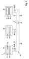
図1では、バスシステム1は、多数の加入者局10、20、30を有し、多数の加入者局10、20、30は、それぞれが、第1のバスワイヤ41および第2のバスワイヤ42を有するバス40に接続されている。バスワイヤ41、42は、CAN_HおよびCAN_LまたはCAN-XL_HおよびCAN-XL_Lとも呼ぶことができ、送信状態での信号に関して、ドミナントレベルのカップリング後またはレセシブレベルもしくは他のレベルの生成後に電気信号伝送に使用される。バス40を介して、信号の形式でのメッセージ45、46を個々の加入者局10、20、30間でシリアル伝送可能である。図1のギザギザの黒いブロック矢印によって示されるように、バス40での通信中にエラーが発生した場合、任意選択でエラーフレーム47(エラーフラグ)を送信することができる。加入者局10、20、30は、例えば自動車の制御機器、センサ、表示装置などである。 In FIG. 1, a bus system 1 has a number of
図1に示されるように、加入者局10は、通信制御デバイス11、送信/受信デバイス12、およびフォーマットチェックモジュール15を有する。加入者局20は、通信制御デバイス21および送信/受信デバイス22を有する。加入者局30は、通信制御デバイス31、送信/受信デバイス32、およびフォーマットチェックモジュール35を有する。加入者局10、20、30の送信/受信デバイス12、22、32は、図1には図示されていないが、それぞれバス40に直接接続されている。 As shown in FIG. 1, the
通信制御デバイス11、21、31は、それぞれの加入者局10、20、30と、バス40に接続されている加入者局10、20、30のうちの少なくとも1つの他の加入者局とのバス40を介した通信をそれぞれ制御する働きをする。 The
通信制御デバイス11、31は、例えば修正されたCANメッセージ45である第1のメッセージ45の作成および読取りを行う。ここで、修正されたCANメッセージ45は、図2を参照してより詳細に述べるCAN XLフォーマットに基づいて構成されており、CAN XLフォーマットでは、それぞれのフォーマットチェックモジュール15、35が使用される。さらに、通信制御デバイス11、31は、必要に応じて、CAN XLメッセージ45またはCAN FDメッセージ46を送信/受信デバイス32に対して提供する、または送信/受信デバイス32から受信するように実装することができる。ここでも、それぞれのフォーマットチェックモジュール15、35が使用される。したがって、通信制御デバイス11、31は、第1のメッセージ45または第2のメッセージ46の作成および読取りを行い、第1および第2のメッセージ45、46は、それらのデータ伝送規格が異なり、すなわちこの場合にはCAN XLまたはCAN FDである。 The
通信制御デバイス21は、ISO11898-1:2015に準拠した従来のCANコントローラのように、すなわちCAN FD許容の従来型CANコントローラまたはCAN FDコントローラのように実装することができる。通信制御デバイス21は、第2のメッセージ46、例えばCAN FDメッセージ46の作成および読取りを行う。CAN FDメッセージ46には、0~64データバイトが含まれることがあり、これらはさらに、従来型CANメッセージよりも明らかに速いデータレートで伝送される。特に、通信制御デバイス21は、従来のCAN FDコントローラのように実装される。 The
送信/受信デバイス22は、ISO11898-1:2015に準拠した従来のCANトランシーバ、またはCAN FDトランシーバのように実装することができる。送信/受信デバイス12、32は、必要に応じて、関連する通信制御デバイス11、31に対してCAN XLフォーマットに従ってメッセージ45を提供する、もしくは現在のCAN FDフォーマットに従ってメッセージ46を提供するように、または関連する通信制御デバイス11、31からメッセージを受信するように実装することができる。 The transmitting/receiving
2つの加入者局10、30を用いて、CAN XLフォーマットでのメッセージ45の作成および伝送、ならびにそのようなメッセージ45の受信を実現可能である。 With two
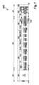
図2は、メッセージ45に関してCAN XLフレーム450を示し、CAN XLフレーム450は、送信/受信デバイス12用の通信制御デバイス11によってバス40への送信のために提供される。この場合、通信制御デバイス11は、図2にも示されているように、この例示的実施形態ではCAN FDと互換性があるものとしてフレーム450を作成する。同じことが、加入者局30の通信制御デバイス31および送信/受信デバイス32にも同様に当てはまる。 FIG. 2 shows a
図2によれば、バス40でのCAN通信のためのCAN XLフレーム450は、異なる通信フェーズ451、452、すなわち調停フェーズ451およびデータフェーズ452に分割される。フレーム450は、調停フィールド453、制御フィールド454、データフィールド455、チェックサムFCRCおよび切替えシーケンスADS用のチェックサムフィールド456、ならびに確認フィールド457を有する。 According to FIG. 2, the
調停フェーズ451において、調停フィールド453での識別子(ID)を用いて、どの加入者局10、20、30がメッセージ45、46を最高の優先順位で送信したいか、したがって後続の時間に関して後続のデータフェーズ452で送信するためにバスシステム1のバス40への排他的アクセスを取得するかが、ビット毎に加入者局10、20、30間で交渉される。調停フェーズ451では、CANおよびCAN-FDと同様に物理層が使用される。物理層は、既知のOSIモデル(オープンシステム相互接続モデル)のビット伝送層または層1に対応する。 In the
フェーズ451中の重要な点は、既知のCSMA/CR法が使用されることであり、CSMA/CR法は、より優先順位の高いメッセージ45、46が破壊されることなく、加入者局10、20、30がバス40に同時にアクセスすることを許可する。これにより、さらなるバス加入者局10、20、30をバスシステム1に比較的容易に追加することができ、これは非常に有利である。 The important point during
CSMA/CR法により、バス40上にいわゆるレセシブ状態が存在することになり、このレセシブ状態は、バス40上で他の加入者局10、20、30がドミナント状態で上書きすることができる。レセシブ状態では、個々の加入者局10、20、30で高抵抗挙動が生じており、これは、バス回路の寄生と組み合わさって、より長い時定数をもたらす。これにより、今日のCAN-FD物理層の最大ビットレートは、実際の車両での使用では現在約2メガビット/秒に制限されている。 The CSMA/CR method results in the existence of a so-called recessive state on the
データフェーズ452では、制御フィールド454の一部に加えて、データフィールド455からのCAN-XLフレームの使用データまたはメッセージ45、ならびにチェックサムFCRCおよびさらにはフィールドDASに関するチェックサムフィールド456が送信され、チェックサムフィールド456は、データフェーズ452からデータフェーズ451に切り替えて戻すために使用される。 In the
加入者局10が送信元として調停に勝ち、したがって加入者局10が送信元として送信のためにバスシステム1のバス40への排他的アクセスを得たときに初めて、メッセージ45の送信元は、バス40でのデータフェーズ452のビットの送信を開始する。 Only when the
ごく一般に、CANまたはCAN FDと比較して、CAN XLを用いるバスシステムでは以下の異なる特性を実現することができる。 Very generally, compared to CAN or CAN FD, bus systems using CAN XL can realize the following different characteristics:
a)CANおよびCAN FDのロバスト性および使いやすさに寄与する実証済みの特性、特に識別子を用いたフレーム構造およびCSMA/CR法による調停の採用および場合によっては適応。 a) Adoption and possibly adaptation of proven properties contributing to the robustness and ease of use of CAN and CAN FD, in particular the frame structure with identifiers and arbitration with CSMA/CR methods.
b)特に毎秒約10メガビットへの正味データ伝送レートの増加。
c)特に約4キロバイトまたは任意の他の値への、フレーム当たりの使用データのサイズの増加。b) An increase in the net data transmission rate, especially to about 10 megabits per second.
c) Increasing the size of the data used per frame, especially to about 4 kilobytes or any other value.
図2に示されるように、加入者局10は、第1の通信フェーズとしての調停フェーズ451において、部分的に、特にFDFビット(これを含む)まで、ISO11898-1:2015に従ってCAN/CAN-FDから知られているフォーマットを使用する。対照的に、加入者局10は、FDFビットから、第1の通信フェーズと、第2の通信フェーズであるデータフェーズ452とにおいて、以下で述べるCAN XLフォーマットを使用する。 As shown in FIG. 2, the
この例示的実施形態では、CAN XLとCAN FDとには互換性がある。ここで、CAN FDから知られているresビット(以下、XLFビットと呼ぶ)は、CAN FDフォーマットからCAN XLフォーマットに切り替えるために使用される。したがって、CAN FDとCAN XLとのフレームフォーマットは、resビットまで同じである。受信側は、resビットにおいて初めて、どのフォーマットでフレームが送信されるかを認識する。CAN XL加入者局、すなわちここでは加入者局10、30は、CAN FDもサポートする。 In this exemplary embodiment, CAN XL and CAN FD are compatible. Here, the res bit (hereinafter referred to as XLF bit) known from CAN FD is used to switch from CAN FD format to CAN XL format. Therefore, the frame formats of CAN FD and CAN XL are the same up to the res bit. Only in the res bit does the receiving side know in which format the frame will be sent. CAN XL subscriber stations, here
11ビットの識別子が使用される図2に示されるフレーム450の代替として、任意選択で、29ビットの識別子が使用されるCAN XL拡張フレームフォーマットも可能である。CAN XL拡張フレームフォーマットは、FDFビットまでは、ISO11898-1:2015からの既知のCAN FD拡張フレームフォーマットと同一である。 As an alternative to the
図2によれば、フレーム450は、SOFビットからFDFビット(これを含む)まで、ISO11898-1:2015に準拠したCAN FDベースフレームフォーマットと同一である。したがって、既知の構造は、本明細書でさらには説明しない。図2において下側の線が太い線分で示されているビットは、フレーム450でドミナントまたは「0」として送信される。図2において上側の線が太い線分で示されているビットは、フレーム450でレセシブまたは「1」として送信される。CAN XLデータフェーズ452では、レセシブレベルとドミナントレベルの代わりに対称的な「1」と「0」のレベルが使用される。 According to FIG. 2, the
一般に、フレーム450の生成には2つの異なるスタッフィング規則が使用される。制御フィールド454でのXLFビットまではCAN FDの動的ビットスタッフィング規則が適用され、したがって連続する5つの同一のビットの後に逆スタッフビットが挿入され得る。制御フィールド454でのresXLビットの後には固定スタッフィング規則が適用され、したがって、固定数のビットの後に固定スタッフビットが挿入され得る。代替として、ただ1つのスタッフビットの代わりに、2つ以上のビットを固定スタッフビットとして挿入することもできる。これについては後でより詳細に述べる。 Generally, two different stuffing rules are used to generate
フレーム450では、FDFビットの直後にXLFビットが続き、XLFビットは、その位置から、前述したようにCAN FDベースフレームフォーマットでの「resビット」に対応する。XLFビットは、1、すなわちレセシブとして送信されるとき、それによりフレーム450をCAN XLフレームとして識別する。CAN FDフレームの場合、通信制御デバイス11は、XLFビットを0、すなわちドミナントとして設定する。 In
XLFビットの後、フレーム450でresXLビットが続き、resXLビットは、将来の使用のためのドミナントビットである。resXLは、フレーム450に関しては、0、すなわちドミナントとして送信されなければならない。しかし、加入者局10がresXLビットを1、すなわちレセシブとして受信した場合、受信側加入者局10は、CAN FDメッセージ46でres=1に関して行われるのと同様に、例えばプロトコル例外状態になる。代替として、resXLビットを正反対に定義することもでき、すなわち、1、すなわちレセシブとして送信されることになる。この場合、受信側加入者局は、ドミナントresXLビットでプロトコル例外状態になる。 The XLF bit is followed in
resXLビットの後、フレーム450で、所定のビットシーケンスが符号化されるシーケンスADS(調停データスイッチ)が続く。このビットシーケンスは、調停フェーズ451のビットレート(調停ビットレート)からデータフェーズ452のビットレート(データビットレート)への単純で確実な切替えを可能にする。例えば、ADSシーケンスのビットシーケンスはAL1ビットからなり、AL1ビットは、ドミナント、すなわち0として送信される。AL1ビットは、調停フェーズ451の最後のビットである。AL1ビットにおいて、送信/受信デバイス12、22、32で物理層が切り替えられる。次の2つのビットDH1とDL1は、すでにデータビットレートで送信される。したがって、CAN XLでのビットDH1およびDL1は、データフェーズ452の時間的に短いビットである。 The resXL bit is followed in
シーケンスADSの後に、フレーム450で、データフィールド455の内容を特徴付けるPTフィールドが続く。この内容は、データフィールド455に含まれる情報のタイプを提示する。例えば、PTフィールドは、データフィールド455に「インターネットプロトコル」(IP)フレーム、またはトンネルされたイーサネットフレームもしくは他のフレームがあるかどうかを提示する。 The sequence ADS is followed in
PTフィールドの後にDLCフィールドが続き、DLCフィールドにはデータ長コード(DLC=Data Length Code)が挿入され、データ長コードは、フレーム450のデータフィールド455内のバイト数を提示する。データ長コード(DLC)は、0からデータフィールド455の最大長またはデータフィールド長までの任意の値を取ることができる。最大データフィールド長が特に2048ビットである場合、DLC=0が1バイトのデータフィールド長を意味し、DLC=2047が2048バイトのデータフィールド長を意味すると仮定して、データ長コード(DLC)は11ビットを必要とする。代替として、例えばCANの場合のように、長さ0のデータフィールド455を許可することができる。この場合、DLC=0は、例えば、0バイトを有するデータフィールド長を符号化する。符号化可能な最大データフィールド長は、例えば11ビットでは、(2^11)-1=2047である。 The PT field is followed by a DLC field, into which is inserted a Data Length Code (DLC), which indicates the number of bytes in
DLCフィールドの後、フレーム450でヘッダチェックサムHCRCが続く。ヘッダチェックサムHCRCは、フレーム450のヘッダを保護するためのチェックサムであり、すなわち、SOFビットでのフレーム450の開始からヘッダチェックサムHCRCの開始までのすべてのビット(ヘッダチェックサムHCRCの開始までのすべての動的スタッフビットおよび任意選択で固定スタッフビットを含む)である。ヘッダチェックサムHCRC、したがって巡回冗長検査(CRC)に従ったチェックサム多項式の長さは、所望のハミング距離に対応して選択され得る。ヘッダチェックサムHCRCによって保護することができるデータワードは、11ビットのデータ長コード(DLC)では、27ビットよりも長い。したがって、ハミング距離6を達成するには、ヘッダチェックサムHCRCの多項式が少なくとも13ビットの長さでなければならない。 The DLC field is followed in
ヘッダチェックサムHCRCの後、フレーム450でデータフィールド455が続く。データフィールド455は、1~n個のデータバイトからなり、ここで、nは、例えば2048バイトもしくは4096バイトまたは他の任意の値である。代替として、0のデータフィールド長も考えられる。データフィールド455の長さは、前述したようにDLCフィールドに符号化される。 The header checksum HCRC is followed in
データフィールド455の後、フレーム450でフレームチェックサムFCRCが続く。フレームチェックサムFCRCは、フレームチェックサムFCRCのビットからなる。フレームチェックサムFCRC、したがってCRC多項式の長さは、所望のハミング距離に従って選択され得る。フレームチェックサムFCRCは、フレーム450全体を保護する。代替として、任意選択で、データフィールド455のみが、フレームチェックサムFCRCで保護される。
フレームチェックサムFCRCの後、フレーム450で、所定のビットシーケンスが符号化されるシーケンスDAS(データ調停スイッチ)が続く。このビットシーケンスは、データフェーズ452のデータビットレートから調停フェーズ451の調停ビットレートへの単純で確実な切替えを可能にする。 The frame checksum FCRC is followed in
例えば、シーケンスDASのビットシーケンスは、レセシブデータビットDH2と、それに続くドミナント調停ビットDL2とからなる。この例では、ビットレートは、上記の2つのビット間のエッジで切り替えることができる。通常、DASフィールドは、3つのビット、すなわちDH2ビット、DL2ビット、およびAH1ビットを有する。これらのビットのうち、最初と最後のビットはレセシブ、すなわち1として送信され、中央のビットはドミナント、つまり0として送信される。 For example, the bit sequence of sequence DAS consists of a recessive data bit DH2 followed by a dominant arbitration bit DL2. In this example, the bit rate can be switched on the edge between the two bits mentioned above. Typically, the DAS field has three bits: DH2 bit, DL2 bit, and AH1 bit. Of these bits, the first and last bits are transmitted as recessive, or 1, and the middle bit is transmitted as dominant, or 0.
前の例とは異なり、この例示的実施形態では、シーケンスDASにフィールドFCPが含まれ、フィールドFCPにより、加入者局10、30、特にそれらのフォーマットチェックモジュール15、35が、受信されたフレーム450内でビットストリームのオフセットを検出することができる。この場合、FCPフィールドのビットパターンが長いほど、受信側加入者局10、30において検出することができるシフトが大きくなる、または強くなる。シフト検出に最も有利なビットパターンは、偶数のMビットを含み、最初のM/2ビットは1を含み、後続のM/2ビットは0を含む。4ビットのFCPフィールドを使用した図2の例では、最初の2ビットはレセシブ、すなわち1として送信される。FCPフィールドの最後の2ビットは、ドミナント、すなわち0として送信される。したがって、図2による4ビットを有するFCPフィールドは、追加のビットDH3、DL3により、DASフィールドの先頭にある通常の2ビットとは異なる。しかし、図2のFCPフィールドのレセシブからドミナントへのエッジは、ビットDH3、DL3を有さない通常のDASフィールドと同じ機能を実現することができる。 Unlike the previous example, in this exemplary embodiment the sequence DAS includes a field FCP, which allows the
一般に、FCPフィールドでは、最初のM/2ビットが0を含み、後続のM/2ビットが1を含むことが可能である。FCPフィールドを用いて、M-1のオフセットを認識することができる。これは、図3を参照して以下でより詳細に述べる。 Generally, in an FCP field, the first M/2 bits may contain 0 and the subsequent M/2 bits may contain 1. The offset of M-1 can be recognized using the FCP field. This is discussed in more detail below with reference to FIG.
シーケンスDASの後、フレーム450で、RPフィールドで始まる確認フィールド457が続く。RPフィールドにおいて同期パターン(Sync Pattern)が維持され、同期パターンは、データフェーズ452の後の調停フェーズ451の開始を受信側加入者局10、30が認識できるようにする。同期パターンは、例えば誤ったヘッダチェックサムHCRCによりデータフィールド455の正しい長さを知らない受信側加入者局10、30が同期することを可能にする。次いで、これらの加入者局は「否定応答」を送信し、誤った受信を報告することができる。これは特に、CAN XLがデータフィールド455でエラーフレーム47(エラーフラグ)をもはや許可しないときに非常に重要である。 The sequence DAS is followed in
RPフィールドの後、確認フィールド(ACKフィールド)457で、フレーム450の受信が正しいことを確定または否定するためのいくつかのビットが続く。図2の例では、ACKビット、ACK-dlmビット、NACKビット、およびNACK-dlmビットが提供される。NACKビットおよびNACK-dlmビットは、任意選択のビットである。受信側加入者局10、30は、フレーム450を正しく受信したとき、ACKビットをドミナントとして送信する。送信側加入者局は、ACKビットをレセシブとして送信する。したがって、フレーム450でバス40に初めに送信されたビットを、受信側加入者局10、30によって上書きすることができる。ACK-dlmビットは、他のフィールドからの分離に使用されるレセシブビットとして送信される。NACKビットおよびNACK-dlmビットは、フレーム450の正しくない受信を受信側加入者局がバス40で信号通知することができるようにするために使用される。これらのビットの機能は、ACKビットおよびACK-dlmビットの機能と同様である。 The RP field is followed by an acknowledgment field (ACK field) 457 with several bits to confirm or deny the correct reception of
確認フィールド(ACKフィールド)457の後、フレーム450で終了フィールド(EOF=End of Frame)が続く。終了フィールド(EOF)のビットシーケンスは、フレーム450の終了を特徴付けるために使用される。終了フィールド(EOF)は、フレーム450の終了時に8つのレセシブビットが送信されることを保証する。これは、フレーム450内では生じ得ないビットシーケンスである。これにより、加入者局10、20、30によってフレーム450の終了を確実に認識することができる。 The acknowledgment field (ACK field) 457 is followed in
終了フィールド(EOF)は、NACKビットでドミナントビットが見られたか、それともレセシブビットが見られたかに応じて異なる長さを有する。送信側加入者局がNACKビットをドミナントとして受信したとき、終了フィールド(EOF)は7つのレセシブビットを有する。そうでない場合には、終了フィールド(EOF)は、5つだけのレセシブビットの長さである。 The end of field (EOF) has different lengths depending on whether a dominant or recessive bit was seen in the NACK bit. When the sending subscriber station receives the NACK bit as dominant, the end of field (EOF) has seven recessive bits. Otherwise, the end of field (EOF) is only five recessive bits long.
終了フィールド(EOF)の後、フレーム450で、フレーム間スペース(IFS-Inter Frame Space)が続く(図2には図示せず)。このフレーム間スペース(IFS)は、ISO11898-1:2015に対応したCAN FDの場合と同様に設計される。 The end field (EOF) is followed by an Inter Frame Space (IFS) at frame 450 (not shown in FIG. 2). This interframe space (IFS) is designed similarly to the case of CAN FD compliant with ISO11898-1:2015.
図3は、通信制御デバイス11、送信/受信デバイス12、および通信制御デバイス11の一部であるフォーマットチェックモジュール15を備えた加入者局10の基本構造を示す。加入者局30は、図3に示されるのと同様に構成されるが、図1によるフォーマットチェックモジュール35は、通信制御デバイス31および送信/受信デバイス32から独立して配置されている。したがって、加入者局30について個別には述べない。 FIG. 3 shows the basic structure of a
図3によれば、加入者局10は、通信制御デバイス11および送信/受信デバイス12に加えて、通信制御デバイス11が割り当てられるマイクロコントローラ13と、システムASIC16(ASIC=特定用途向け集積回路)とを有する。システムASIC16は、代替として、加入者局10の電子回路アセンブリに必要な複数の機能が組み合わされたシステムベースチップ(SBC)でよい。システムASIC16には、送信/受信デバイス12に加えて、送信/受信デバイス12に電気エネルギーを供給するエネルギー供給デバイス17が設置される。通常、エネルギー供給デバイス17は、5Vの電圧CAN_Supplyを送達する。しかし、要件に応じて、エネルギー供給デバイス17は、異なる値を有する異なる電圧を送達することができる。追加または代替として、エネルギー供給デバイス17は、電源として設計することができる。 According to FIG. 3, the
フォーマットチェックモジュール15は、挿入ブロック151および評価ブロック152を有し、これらのブロックについて以下でより詳細に述べる。 The
送信/受信デバイス12は、送信モジュール121および受信モジュール122をさらに有する。以下では常に送信/受信デバイス12に言及するが、代替として、送信モジュール121の外部の別個のデバイスに受信モジュール122を提供することが可能である。送信モジュール121および受信モジュール122は、従来の送信/受信デバイス22と同様に構成することができる。送信モジュール121は、特に、少なくとも1つの演算増幅器および/または少なくとも1つのトランジスタを有することができる。受信モジュール122は、特に、少なくとも1つの演算増幅器および/または少なくとも1つのトランジスタを有することができる。 Transmitting/receiving
送信/受信デバイス12は、バス40、より正確に言うとCAN_HまたはCAN-XL_H用のバス40の第1のバスワイヤ41、およびCAN_LまたはCAN-XL_L用のバス40の第2のバスワイヤ42に接続される。第1および第2のバスワイヤ41、42に電気エネルギー、特に電圧CAN-Supplyを供給するためのエネルギー供給デバイス17用の電圧供給が、少なくとも1つの接続端子43を介して行われる。接地またはCAN_GNDとの接続は、接続端子44を介して実現される。第1および第2のバスワイヤ41、42は、終端抵抗49で終端されている。 The transmitting/receiving
第1および第2のバスワイヤ41、42は、送信/受信デバイス12において、送信モジュール121(送信機とも呼ぶ)だけでなく、受信モジュール122(受信機とも呼ぶ)にも接続されている。見やすくするために図3にはこの接続を示していない。 The first and
バスシステム1の動作時、送信モジュール121は、通信制御デバイス11の送信信号TXDまたはTxDを、バスワイヤ41、42に関する対応する信号CAN-XL_HおよびCAN-XL_Lに変換し、これらの信号CAN-XL_HおよびCAN-XL_Lを、バス40でCAN_HおよびCAN_L用の接続端子に送信する。 During operation of the bus system 1, the
受信モジュール122は、図4によるバス40から受信された信号CAN-XL_HおよびCAN-XL_Lから、受信信号RXDまたはRxDを生成し、図3に示されるように、これを通信制御デバイス11に転送する。アイドルまたはスタンバイ状態(idleまたはStandby)を除いて、受信モジュール122を備えた送信/受信デバイス12は、通常動作では、送信/受信デバイス12がメッセージ45の送信元であるか否かに関係なく、バス40でのデータまたはメッセージ45、46の伝送を常にリッスンする。 The
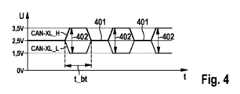
図4の例によれば、信号CAN-XL_HおよびCAN-XL_Lは、少なくとも調停フェーズ451において、CANから知られているようにドミナントおよびレセシブバスレベル401、402を有する。バス40に差分信号VDIFF=CAN-XL_H-CAN-XL_Lが生じ、これは図5に示されている。ビット時間t_btを有する信号VDIFFの個々のビットは、0.7Vの受信閾値で認識することができる。データフェーズ452では、信号CAN-XL_HおよびCAN-XL_Lのビットは、調停フェーズ451よりも速く、すなわち短いビット時間t_btで送信される。したがって、信号CAN-XL_HおよびCAN-XL_Lは、データフェーズ452で、少なくともそれらのビットレートが速いという点で、従来の信号CAN_HおよびCAN_Lとは異なる。 According to the example of FIG. 4, signals CAN-XL_H and CAN-XL_L have dominant and
図4での信号CAN-XL_H、CAN-XL_Lに関する状態401、402のシーケンス、およびそこから得られる図5の電圧VDIFFのプロファイルは、加入者局10の機能を説明する目的のものにすぎない。バス状態401、402に関するデータ状態のシーケンスは、必要に応じて選択可能である。 The sequence of
言い換えると、図4による第1の動作モードでは、送信モジュール121は、バス40のバスラインの2つのバスワイヤ41、42に関して異なるバスレベルを有するバス状態402として第1のデータ状態を生成し、バス40のバスラインの2つのバスワイヤ41、42に関して同じバスレベルを有するバス状態401として第2のデータ状態を生成する。 In other words, in the first mode of operation according to FIG. A second data state is generated as a
さらに、送信モジュール121は、データフェーズ452を含む第2の動作モードにおける信号CAN-XL_H、CAN-XL_Lの時間プロファイルのために、より高いビットレートでビットをバス40に送信する。CAN-XL_HおよびCAN-XL_L信号は、データフェーズ452でさらに、CAN FDの場合とは異なる物理層を用いて生成することもできる。それにより、データフェーズ452でのビットレートは、CAN FDの場合よりもさらに増加させることができる。 Furthermore, the transmitting
図3のフォーマットチェックモジュール15、特にその挿入ブロック151は、加入者局10がフレーム450の送信元として動作するときに、FCPフィールドをフレーム450に挿入する働きをする。図2の例では、挿入ブロック151は、ただ1つのFCPフィールドのみをフレーム450に挿入した。フレーム450の終わりでのシフトも検出可能であるように、FCPフィールドは、フレーム450内のできるだけ遅い時点に配置される。図2に例として示されるように、フレームチェックサムFCRCの後に配置することが非常に有利である。これが最後の可能な位置だからである。 The
図3のフォーマットチェックモジュール15は、この例示的実施形態では、FCPフィールドがDASフィールドのDH2ビットおよびDL2ビットに置き換わるように設計されている。このために、DH2/DL2の機能が維持されたままであるように、FCPフィールドを1100または111000などとして選択しなければならない。したがって、FCPフィールドは、確実なフォーマットチェックを可能にするだけでなく、データフェーズ452から調停フェーズ451への切替え前の同期エッジとしても働く。したがって、FCPフィールドは2つの異なる機能を有する。それにより、FCPフィールドは、できるだけ少ないデータオーバーヘッドしか生成しない。 The
任意選択で、図3のフォーマットチェックモジュール15は、代替または追加としてFCPフィールドをADSフィールドに組み込むように設計される。したがって、挿入ブロック151は、少なくとも1つのFCPフィールドをフレーム450に挿入することができる。 Optionally, the
図3のフォーマットチェックモジュール15の評価ブロック152は、FCPフィールドを使用して、バス40から受信されたビットストリームのフォーマットをチェックする働きをする。
例えば、FCPフィールドがM=4ビットの場合、挿入ブロック151は、FCPフィールドを「1100」または「0011」として挿入することができる。したがって、FCPフィールドは、「1100」または「0011」として送信される。受信側加入者局10が、評価ブロック152を用いてFCPフィールドに関する別の値をサンプリングした場合、評価ブロック152は、フレーム450のビットストリームのシフトがあると評価する。FCPフィールドでのそのようなビットシーケンスにより、受信側加入者局10は、評価ブロック152を用いて、バス40から受信されたビットストリームが左にM-1=3ビットまたは右にM-1=3ビットだけシフトしたことを確実に認識することができる。これを以下の表に示す。 For example, if the FCP field has M=4 bits, the

表では、xは、任意のビット値、すなわち0または1を表す。表の中央に示されているように、FCPフィールドは「1100」として送信される。エッジオフセットが生じず、したがってビットストリームのシフトが生じない場合、受信側加入者局もFCPフィールドを「1100」としてサンプリングする。 In the table, x represents any bit value,
この表では、送信されたフィールド「1100」の上下に、この例ではフレーム450の送信元ではない受信側加入者局(受信ノード)10が、エラーによりビットストリームをオフセットしてサンプリングしている事例が示されている。「右へ3ビットのシフト」とは、受信側加入者局(受信ノード)のビューが3ビットだけオフセットされる、すなわち、この場合には3ビット遅れることを意味する。 This table shows an example where the receiving subscriber station (receiving node) 10, which is not the source of
したがって、受信側加入者局(受信ノード)10は、送信されたFCPフィールドの最後のビットを、受信されたFCPフィールドの最初のビットとしてサンプリングする。このとき、受信されたFCPフィールドの他の3ビットは別の値を有し、ここでは「x」で示されている。 Therefore, the receiving subscriber station (receiving node) 10 samples the last bit of the transmitted FCP field as the first bit of the received FCP field. At this time, the other three bits of the received FCP field have another value, here indicated by "x".
「左へ1ビットのシフト」とは、受信側加入者局(受信ノード)10のビューが1ビットだけオフセットされる、すなわち、この場合には1ビット早くなることを意味する。したがって、受信側加入者局(受信ノード)10は、送信されたFCPフィールドの最初の3ビットを、受信されたFCPフィールドの最後のビットとしてサンプリングする。 "Shifting one bit to the left" means that the view of the receiving subscriber station (receiving node) 10 is offset by one bit, ie, in this case one bit earlier. Therefore, the receiving subscriber station (receiving node) 10 samples the first three bits of the transmitted FCP field as the last bits of the received FCP field.
表から分かるように、受信側加入者局(受信ノード)10によってサンプリングされたFCPフィールドの値は、FCPフィールドの予想される値から常に少なくとも1ビット異なるシフトの際に、「x」で示されるビットがどの値を有するかに依存しない。したがって、受信側加入者局(受信ノード)10、特にそのフォーマットチェックモジュール15、より正確にはその評価ブロック152は、シフト、すなわち受信されたビットストリームのエラーを認識することができる。評価ブロック152は、対応する通知を通信制御デバイス11に出力する。これにより、エラー時に、受信されたフレーム450を削除することができる。その結果、通信制御デバイス11は、エラーフレーム47をバス40に送信することができる。 As can be seen from the table, the value of the FCP field sampled by the receiving subscriber station (receiving node) 10 is always different from the expected value of the FCP field by at least one bit upon shifting, indicated by an "x". It does not depend on what value the bit has. Therefore, the receiving subscriber station (receiving node) 10, in particular its
この例示的実施形態のFCPフィールドの固定値の別の例によれば、FCPフィールドは6ビットを有し、M=6ビットが成り立つ。したがって、挿入ブロック151は、FCPフィールドを「111000」または「000111」として挿入する。したがって、FCPフィールドは「111000」または「000111」として送信される。フレームの送信元でない受信側加入者局10)が、評価ブロック152を用いてFCPフィールドに関する別の値をサンプリングした場合、評価ブロック152は、ビットストリームのシフトがあると評価する。FCPフィールドでのそのようなビットシーケンスにより、受信側加入者局10は、評価ブロック152を用いて、バス40から受信されたビットストリームが左または右にM-1=5ビットだけシフトしたことを確実に認識することができる。 According to another example of a fixed value of the FCP field in this exemplary embodiment, the FCP field has 6 bits, such that M=6 bits. Therefore, insert block 151 inserts the FCP field as "111000" or "000111". Therefore, the FCP field is sent as "111000" or "000111". If a receiving subscriber station 10) that is not the source of the frame samples another value for the FCP field using
当然、FCPフィールドの他の固定長、したがってFCPフィールドの別の固定値も考えられる。 Naturally, other fixed lengths of the FCP field and therefore other fixed values of the FCP field are also conceivable.
この例示的実施形態の変形形態によれば、FCPフィールドは可変の内容を有する。
FCPフィールドのそのような可変の内容の例として、FCPフィールドで固定スタッフビット数を伝送することができる。固定スタッフビット数は、フレーム450の長さに依存する。FCPフィールドの幅、すなわちフレーム450においてFCPフィールドのために提供されているビット数が固定スタッフビットの総数を伝送するのに十分でない場合、固定スタッフビットカウンタの最下位ビットのみを送信することができる。According to a variant of this exemplary embodiment, the FCP field has variable content.
As an example of such variable content of the FCP field, a fixed number of stuff bits may be transmitted in the FCP field. The fixed number of stuff bits depends on the length of
FCPフィールドのそのような可変の内容の別の例として、送信元加入者局(送信ノード)から送信されるフレーム450の数をFCPフィールドで伝送することができる。送信ノードから送信されたフレーム450の数は、フレームカウンタとも呼ぶことができる。 As another example of such variable content of the FCP field, the number of
図6は、CAN XLとCAN FDとの互換性がある第2の例示実施形態によるフレーム450_1を示す。この例示的実施形態では、フレーム450_1、したがってCAN XLフレームフォーマットは、以下で述べるように、図2のフレーム450とは異なる。ここでは、図2のフレーム450との相違点を以下に述べる。なお、2つの例示的実施形態のフレーム450、450_1は同じである。 FIG. 6 shows a frame 450_1 according to a second exemplary embodiment that is compatible with CAN XL and CAN FD. In this exemplary embodiment, frame 450_1, and thus the CAN XL frame format, is different from
フレーム450_1には、少なくとも2つのFCPフィールドがある。図6の例では、フレーム450_1で、ヘッダチェックサムHCRCの後にFCPフィールドFCP1が挿入され、フレームチェックサムFCRCの後にFCPフィールドFCP2が挿入される。また、フレーム450_1では、FCPフィールドFCP1、FCP2は、例としてM=4ビットの長さを有する。当然、FCPフィールドに関する別の長さを選択することもできる。特に、FCPフィールドFCP1、FCP2の長さ、つまりビット数が異なることがあり得る。 There are at least two FCP fields in frame 450_1. In the example of FIG. 6, in frame 450_1, an FCP field FCP1 is inserted after the header checksum HCRC, and an FCP field FCP2 is inserted after the frame checksum FCRC. Further, in frame 450_1, FCP fields FCP1 and FCP2 have a length of M=4 bits, for example. Naturally, other lengths for the FCP field can also be chosen. In particular, the lengths of the FCP fields FCP1 and FCP2, that is, the number of bits, may be different.
ごく一般に、挿入ブロック151は、フレーム450_1での任意の位置にFCPフィールドを挿入するように設計することができる。評価ブロック152は、対応する挿入位置にあるFCPフィールドを探し、したがって受信されたフレーム450_1を評価するように設計される。 Very generally,
特に、挿入ブロック151は、送信すべきフレーム450_1にFCPフィールドを複数回挿入するように設計される。例えば、常に同じ内容を有するFCPフィールドは、常に所定数のデータの後に、特に常に128バイトのデータまたは任意の他の値の後に挿入することができる。当然、他の例も考えられる。 In particular, the
図7は、CAN XLとCAN FDとのフレームフォーマットに互換性がない、第3の例示的実施形態によるフレーム4500を示す。この例示的実施形態では、フレーム4500、したがってCAN XLフレームフォーマットは、以下で述べるように、図2のフレーム450とは異なる。ここでは、図2のフレーム450との相違点のみを述べる。なお、2つの例示的実施形態のフレーム450、4500は同じである。 FIG. 7 shows a
一般に、この例示的実施形態によるフレーム4500の生成時、固定スタッフィング規則のみが使用され、したがって、固定数のビットの後に固定スタッフビットが挿入され得る。代替として、ただ1つのスタッフビットの代わりに、2つ以上のビットを固定スタッフビットとして挿入することもできる。データ長コード(DLC)の値がわかっている場合、これは一定のフレーム長またはフレーム4500の一定の長さをもたらす。これにより、動的スタッフビットによって引き起こされる様々な問題が防止される。 In general, only fixed stuffing rules are used when generating
この例示的実施形態によるフレーム4500では、識別子(ID)は、CAN FDの場合のように11ビットまたは29ビットにもはや制限されない。識別子(ID)のビットの数kは自由に選択することができる。しかし、代替として、数kは、固定値に固定することもできる。正味データレートが高い場合、k=8ビットのIDが好適である。これは、バスシステム1の各加入者局10、20、30に十分に多くのバスアクセス優先順位を与えるのに十分である。しかし、当然、バスシステム1での要件および様々な優先順位の数に応じて、kに関して別の値を選択可能である。 In
図2のフレーム450のビットRRS、IDE、FDF、XLFは、フレーム4500では不要になり、省略される。これにより4ビットが節約され、したがってフレームオーバーヘッドが低減される。これにより、バスシステム1での正味データレートが増加される。 Bits RRS, IDE, FDF, and XLF of
終了フィールド(EOF)は、NACKビットがドミナントであるとき、フレーム4500でさらに5ビットだけを有する。一方、NACKビットがレセシブであるとき、終了フィールド(EOF)は3ビットを有する。終了フィールド(EOF)は、フレーム450の終了時に6つのレセシブビットが送信されることを保証する。この数のレセシブビットは、調停フェーズ451において5つの同一ビットの後に固定スタッフビットが挿入されるとき、有効なフレーム4500では他のどこにも生じ得ない。代替として、7ビット以上でもよい。特に、EOFビットの数は、固定スタッフビットが挿入される前のビットの数に適合させる必要がある。 The end of field (EOF) only has 5 more bits in
フレーム間スペース(IFS)は、フレーム4500で最小長さを必要としない。特に、フレーム間スペース(IFS)は長さ0を有することができる。そのような場合、2つのフレーム4500が、順次にシームレスに送信される。しかし、例えば1ビットを有するフレーム間スペース(IFS)は、前述した場合と比較してバスシステム1のロバスト性を高めるためにも好適である。2つのフレーム4500間のここでは7つのレセシブビットによって、新たな加入者局は、バス40でより確実に同期することができる。 Interframe space (IFS) does not require a minimum length in
第4の例示的実施形態によれば、FCPフィールドは固定スタッフビットとして使用される。言い換えると、固定スタッフビットの代わりに、挿入ブロック151は、フレーム450にFCPフィールドを挿入するように設計される。そのような場合、2つのスタッフビット間で小さなシフトしか生じ得ないので、例えばM=2ビットの長さを有する短いFCPフィールドで十分である。 According to a fourth exemplary embodiment, the FCP field is used as fixed stuff bits. In other words, instead of fixed stuff bits, the
したがって、この例示的実施形態でも、FCPフィールドは、2つの異なる機能、すなわちスタッフビットおよびフォーマットチェックを有する。 Therefore, also in this exemplary embodiment, the FCP field has two different functions: stuffing bits and format checking.
長さM=2ビットを有するFCPフィールドにより、データオーバーヘッドは非常にわずかしか発生しないか、さらにはまったく発生しない。これについては、以下でより詳細に説明する。 With an FCP field having length M=2 bits, very little or even no data overhead occurs. This will be explained in more detail below.
この例示的実施形態では、固定スタッフビットの代わりに、常に、一定の内容を有するFCPフィールドが使用される。FCPフィールドでのビットパターンは、FCPフィールドが同期エッジを含むように、挿入ブロック151によって選択される。CAN XLが立ち下がりエッジに同期する場合、FCPフィールドに関して値「10」が有利である。CAN XLが立ち上がりエッジに同期される場合、FCPフィールドに関して値「01」が有利である。 In this exemplary embodiment, instead of fixed stuff bits, an FCP field with constant content is always used. The bit pattern in the FCP field is selected by
固定スタッフビットでは、同期に関して最悪の場合には、1つおきのスタッフビットの後にのみ立ち下がりエッジがある。FCPフィールドでは常に同期することができるので、2つのFCPフィールド間の距離は、受信側加入者局10、30(受信ノード)の同期を損なうことなく、2つの固定スタッフビット間の距離の2倍にすることができる。 With fixed stuff bits, in the worst case for synchronization, there is a falling edge after only every other stuff bit. Since FCP fields can always be synchronized, the distance between two FCP fields can be twice the distance between two fixed stuff bits without compromising the synchronization of the receiving
FCPフィールドは2ビットを有するが、固定スタッフビットの半分の頻度でしか生じないため、FCPフィールドによるデータオーバーヘッドは、固定スタッフビットによって生成されるデータオーバーヘッドと同一である。 Although the FCP field has two bits, it occurs only half as often as the fixed stuff bits, so the data overhead due to the FCP field is the same as the data overhead produced by the fixed stuff bits.
FCPフィールドの大きな利点は、その内容が一定であることである。それにより、データストリームのシフトを確実に確定可能である。M=2ビットでの上述した例では、受信側加入者局10、30(受信ノード)での1ビットシフトを確実に認識することができる。FPCフィールドがフレーム内で頻繁に現れることにより、シフトを即座に効果的に認識することができる。それにより、受信されたフレーム450でのエラーを非常に迅速に認識することができ、フレーム450の送信を迅速に中断することができる。これは、バスシステム1における使用データのより高速な伝送に寄与する。 A major advantage of the FCP field is that its contents are constant. Thereby, the shift of the data stream can be determined reliably. In the example described above with M=2 bits, a 1-bit shift at the receiving
この例示的実施形態の変形形態によれば、受信側加入者局10、30(CAN XL受信ノード)は、各立ち下がりエッジで再同期する代わりに、FCPフィールドのエッジでのみ再同期を行うことができる。再同期が所要のエッジに制限されることによって、受信側加入者局10、30(CAN XL受信ノード)が、妨害されたエッジに同期してエラーを挿入するリスクを低減する。 According to a variant of this exemplary embodiment, the receiving
この例示的実施形態のこの変形形態の大きな利点は、ここでFCPフィールドでのエッジを明示的に妨害しない限り誤同期が生じ得ないため、再同期エラーの数が減少することである。 A great advantage of this variant of this exemplary embodiment is that the number of resynchronization errors is reduced, since now no false synchronization can occur unless edges in the FCP field are explicitly disturbed.
第5の例示的実施形態によれば、FCPフィールドは、前の例示的実施形態と同様に固定スタッフビットとして再び使用される。しかし、この例示的実施形態では、固定スタッフビットの代わりに、可変の内容を有するFCPフィールドが常に使用される。したがって、この例示的実施形態でも、FCPフィールドは、2つの異なる機能、すなわちスタッフビットおよびフォーマットチェックを有する。 According to the fifth exemplary embodiment, the FCP field is again used as fixed stuff bits as in the previous exemplary embodiment. However, in this exemplary embodiment, instead of fixed stuff bits, an FCP field with variable content is always used. Therefore, also in this exemplary embodiment, the FCP field has two different functions: stuffing bits and format checking.
ここで、挿入ブロック151は、常にスタッフビットの値に適合するFCPフィールドを選択する。スタッフビットは2つの値、すなわち0または1を有することができるので、2つの異なるFCPフィールドが想定される。したがって、挿入ブロック151は、値「01」を有するFCPフィールドFCP_Aを挿入する、または値「10」を有するFCPフィールドFCP_Bを挿入することができる。 Here, the
したがって、挿入ブロック151は、スタッフビットの取り得る値に応じてFCPフィールドを挿入する。例えば、スタッフビットが0であるとき、FCPフィールドFCP_Aが挿入されて送信される。スタッフビットが1の場合、FCPフィールドFCP_Bが挿入されて送信される。 Therefore, the
FCPフィールドの可変の内容の原理は、挿入ブロック151に関して、当然、他のFCPフィールドを生成するためにも適用可能である。 The principle of variable content of the FCP field can of course also be applied for generating other FCP fields with respect to the
第6の例示的実施形態によれば、AH1ビットは、追加のまたは唯一のFCPフィールドとして使用される。これは、CAN XLの標準化の現状に従って、AH1ビットが他の方法で評価されないときに可能である。現在、AH1ビットは、送信/受信デバイス12、32において物理層をデータフェーズ452から調停フェーズ451に切り替えるための時間を設けるためにのみ使用される。 According to a sixth exemplary embodiment, the AH1 bit is used as an additional or only FCP field. This is possible when the AH1 bit is not evaluated in any other way, according to the current state of CAN XL standardization. Currently, the AH1 bit is only used to provide time for switching the physical layer from the
そのような場合、受信ノードは、例えばTXD回線を介して、物理層の切替えを送信/受信デバイス12、32に信号通知することができる。受信ノードはそのTXD回線を送信に使用しないので、これが可能である。送信ノードはそのTXD回線を送信に使用するので、送信ノードではこれは不可能である。 In such a case, the receiving node may signal the physical layer switch to the transmitting/receiving
したがって、受信ノード、または受信側加入者局としての加入者局10は、その評価ブロック152でAH1ビットを評価する、すなわちサンプリングすることができる。AH1ビットは定数値を有するので、受信されたフレームのフォーマットチェックにも使用される。AH1ビットは、受信ノードがビットストリームをオフセットしてサンプリングしているかどうかを認識するのに役立つ。これにより、受信されたフレームのフォーマットチェックを確実に行うことができ、またはFCPフィールドを追加することでさらに強化することができる。 The
AH1ビットの評価は、受信されたフレーム450のフォーマットチェックがデータオーバーヘッドを引き起こさないという利点を有する。したがって、この例示的実施形態でも、FCPフィールドは、2つの異なる機能、すなわち従来のAH1ビットの機能およびフォーマットチェックを有する。 Evaluation of the AH1 bit has the advantage that format checking of the received
加入者局10、20、30、バスシステム1、およびそこで実施される方法の前述したすべての構成は、個別に、またはすべての可能な組合せで使用することができる。特に、上述した例示的実施形態のすべての特徴および/またはそれらの変形形態は、任意に組み合わせることができる。追加または代替として、特に以下の変形形態が考えられる。 All the aforementioned configurations of the
CANバスシステムの例で本発明を前述してきたが、本発明は、異なる通信フェーズのために生成されるバス状態が異なる、2つの異なる通信フェーズが使用される各通信ネットワークおよび/または通信方法で使用することができる。特に、本発明は、イーサネットおよび/または100Base-T1イーサネット、フィールドバスシステムなどの他のシリアル通信ネットワークの開発に使用可能である。 Although the invention has been described above with the example of a CAN bus system, the invention applies to each communication network and/or communication method in which two different communication phases are used, where the bus states generated for the different communication phases are different. can be used. In particular, the invention can be used in the development of Ethernet and/or other serial communication networks such as 100Base-T1 Ethernet, fieldbus systems, etc.
特に、例示的実施形態によるバスシステム1は、データを2つの異なるビットレートでシリアル伝送可能である通信ネットワークでよい。バスシステム1において、共通のチャネルへの加入者局10、20、30の排他的で衝突のないアクセスが少なくとも特定の期間にわたって保証されていることは、有利であるが、必須の前提条件ではない。 In particular, the bus system 1 according to an exemplary embodiment may be a communication network in which data can be transmitted serially at two different bit rates. It is advantageous, but not a necessary precondition, that in the bus system 1 exclusive and collision-free access of the
例示的実施形態のバスシステム1における加入者局10、20、30の数および配置は任意である。特に、バスシステム1での加入者局20は省略することができる。加入者局10または30のうちの1つまたは複数がバスシステム1に存在することが可能である。バスシステム1内のすべての加入者局が同一に設計される、すなわち加入者局10のみまたは加入者局30のみが存在することも考えられる。 The number and arrangement of
Claims (16)
Translated fromJapanese前記バスシステム(1)の加入者局(10;30)と少なくとも1つの他の加入者局(10;20;30)との通信を制御するための通信制御デバイス(11;31)と、
前記通信制御デバイス(11;31)によって生成された送信信号(TXD)を前記バスシステム(1)のバス(40)上に送信するための送信/受信デバイス(12;32)とを備え、前記バスシステム(1)の加入者局(10、20、30)間で交換されるメッセージ(45)に関して、前記バス(40)に第1の通信フェーズ(451)で送信される信号のビット時間(t_bt)が、第2の通信フェーズ(452)で送信される信号のビット時間(t_bt)とは異なることがあり、
前記通信制御デバイス(11;31)が、フレーム(450;450_1;4500)に従って前記送信信号(TXD)を生成し、前記フレーム(450;450_1;4500)に少なくとも1つのフィールド(FCP;FCP_1;FCP_2)を挿入するように設計され、前記少なくとも1つのフィールド(FCP;FCP_1;FCP_2)は、前記フレーム(450;450_1;4500)を受信する、前記フレーム(450;450_1;4500)の送信元ではない前記バスシステム(1)の前記他の加入者局(10;20;30)での前記フレーム(450;450_1;4500)のビットストリームが、予想される前記フレーム(450;450_1;4500)と比較して少なくとも1ビットだけオフセットされているかどうかをチェックするように設計され、
前記通信制御デバイス(11;31)は、前記加入者局(10;30)が前記フレーム(450;450_1;4500)の送信元ではない場合において、前記少なくとも1つのフィールド(FCP;FCP_1;FCP_2)を用いて、受信された前記フレーム(450;450_1;4500)の前記ビットストリームが、予想される前記フレーム(450;450_1;4500)と比較して少なくとも1ビットだけオフセットされているかどうかをチェックするように設計される、加入者局(10;30)。A subscriber station (10; 30) for a serial bus system (1), comprising:
a communication control device (11; 31) for controlling communication between a subscriber station (10; 30) and at least one other subscriber station (10; 20; 30) of said bus system (1);
a transmitting/receiving device (12; 32) for transmitting a transmission signal (TXD) generated by the communication control device (11; 31) onto the bus (40) of the bus system (1); Regarding messages (45) exchanged between subscriber stations (10, 20, 30) of a bus system (1), the bit time ( t_bt) may be different from the bit time (t_bt) of the signal transmitted in the second communication phase (452);
The communication control device (11; 31) generates the transmission signal (TXD) according to a frame (450; 450_1; 4500), and includes at least one field (FCP; FCP_1; FCP_2) in the frame (450; 450_1; 4500). ), and said at least onefield (FCP; FCP_1; FCP_2)is not a source of said frame (450; 450_1; 4500) receiving said frame (450; 450_1; 4500). The bitstream of the frame (450; 450_1; 4500) atthe other subscriber station (10; 20; 30) of the bus system (1) is comparedwith the expected frame (450; 450_1; 4500). is designed to check if it is offset by at least 1 bit,
The communication control device (11; 31) controls the at least one field (FCP; FCP_1; FCP_2) when the subscriber station (10; 30) is not the source of the frame (450; 450_1; 4500) checking whether the bitstream of the received frame (450; 450_1; 4500) is offset by at least one bit compared to the expected frame (450; 450_1; 4500) using A subscriber station (10; 30), designed to :
前記通信制御デバイス(11;31)が、すべての固定スタッフビットを固定ビットスタッフィング規則に従って前記フレーム(450;450_1;4500)に挿入する、いずれかの固定ビットスタッフィング規則に従って、固定数のビットの後に固定スタッフビットを挿入し得るように設計される、
請求項1から6のいずれか1項に記載の加入者局(10;30)。said communication control device (11; 31) is designed to insert said at least one field (FCP; FCP_1; FCP_2) as a fixed stuff bit into said frame (450; 450_1; 4500);
after a fixed number of bits according to any fixed bit stuffing rule, said communication control device (11; 31) inserts all fixed stuff bits into said frame (450; 450_1; 4500) according to a fixed bit stuffing rule. designed to insert fixed stuff bits,
Subscriber station (10; 30) according to any one of claims 1 to6 .
Mビットの第1の半分がそれぞれ同じ第1の値を有し、
Mビットの第2の半分が、それぞれ同じ第2の値を有し、前記第2の値が前記第1の値と逆である、
請求項9に記載の加入者局(10;30)。said communication control device (11; 31) is designed to use an even number of M bits for said at least one field (FCP; FCP_1; FCP_2);
the first halves of the M bits each have the same first value;
second halves of the M bits each have the same second value, said second value being opposite to said first value;
Subscriber station (10; 30) according to claim9 .
前記通信制御デバイス(11;31)は、前記バスシステム(1)の前記他の加入者局(10;20;30)が前記フレーム(450;450_1;4500)を受信するが、前記フレーム(450;450_1;4500)の送信元ではない場合、前記ビット(AH1)を使用して、受信された前記フレーム(450;450_1;4500)の前記ビットストリームが予想される前記フレーム(450;450_1;4500)と比較して少なくとも1ビットだけオフセットされているかどうかをチェックするように設計される、
請求項1から12のいずれか1項に記載の加入者局(10;30)。The communication control device (11; 31) is designed to provide a bit (AH1) after switching from the second communication phase (452) to the first communication phase (451), during which the transmission / the receiving device (12; 32) has time to switch to said second communication phase (452);
The communication control device (11; 31) is arranged such thatthe other subscriber stations (10; 20; 30) of the bus system (1) receive the frame (450; 450_1; 4500), but the communication control device (11; ;450_1;4500), the bit (AH1) is used to determine whether the received bitstream of the frame (450;450_1;4500) is the source of the expected frame (450;450_1;4500). ) is designed to check whether it is offset by at least one bit compared to
Subscriber station (10; 30) according to any one of claims 1 to12 .
前記第1の通信フェーズ(451)において、前記バスシステム(1)の前記他の加入者局(10、20、30)のどれが、後続の前記第2の通信フェーズ(452)で前記バス(40)への少なくとも一時的に排他的で衝突のないアクセスを得るかが交渉される、
請求項1から13のいずれか1項に記載の加入者局(10;30)。the frame (450; 450_1) formed for the message (45) is configured to be compatible with CAN FD;
In said first communication phase (451), which of saidother subscriber stations (10, 20, 30) of said bus system (1) communicates with said bus ( 40) is negotiated to obtain at least temporarily exclusive and conflict-free access to
Subscriber station (10; 30) according to any one of claims 1 to13 .
少なくとも2つの加入者局(10;20;30)とを備えるバスシステム(1)であって、前記少なくとも2つの加入者局(10;20;30)が、互いにシリアル通信できるように、前記バス(40)を介して互いに接続されており、そのうちの少なくとも1つの加入者局(10;30)が、請求項1から14のいずれか1項に記載の加入者局(10;30)である、
バスシステム(1)。Bus (40) and
A bus system (1) comprising at least two subscriber stations (10; 20; 30), wherein theat least two subscriber stations (10; 20; 30) (40), of which at least one subscriber station (10; 30) is a subscriber station (10; 30) according to any one of claims 1 to 14. ,
Bus system (1).
前記通信制御デバイス(11;31)を用いて、前記加入者局(10;30)と、前記バスシステム(1)の少なくとも1つの他の加入者局(10;20;30)との通信を制御するステップと、
前記送信/受信デバイス(12;32)によって、前記通信制御デバイス(11;31)によって生成された送信信号(TXD)を前記バスシステム(1)のバス(40)上に送信するステップであって、前記バスシステム(1)の加入者局(10、20、30)間で交換されるメッセージ(45)に関して、前記バス(40)に第1の通信フェーズ(451)で送信される信号のビット時間(t_bt)が、第2の通信フェーズ(452)で送信される信号のビット時間(t_bt)とは異なることがある、ステップと
を含み、
前記通信制御デバイス(11;31)が、フレーム(450;450_1;4500)に従って前記送信信号(TXD)を生成し、前記フレーム(450;450_1;4500)に少なくとも1つのフィールド(FCP;FCP_1;FCP_2)を挿入し、前記少なくとも1つのフィールド(FCP;FCP_1;FCP_2)は、前記フレーム(450;450_1;4500)を受信する、前記フレーム(450;450_1;4500)の送信元ではない前記バスシステム(1)の前記他の加入者局(10;20;30)での前記フレーム(450;450_1;4500)のビットストリームが、予想される前記フレーム(450;450_1;4500)と比較して少なくとも1ビットだけオフセットされているかどうかをチェックするように設計され、
前記通信制御デバイス(11;31)は、前記加入者局(10;30)が前記フレーム(450;450_1;4500)の送信元ではない場合において、前記少なくとも1つのフィールド(FCP;FCP_1;FCP_2)を用いて、受信された前記フレーム(450;450_1;4500)の前記ビットストリームが、予想される前記フレーム(450;450_1;4500)と比較して少なくとも1ビットだけオフセットされているかどうかをチェックするように設計される、方法。A communication method in a serial bus system (1), implemented by a subscriber station (10; 30) of said bus system (1), said subscriber station (10; 30) comprising a communication control device (11; 31) and a transmitting/receiving device (12; 32), the method comprising:
The communication control device (11; 31) is used to control the communication between the subscriber station (10; 30) and at least one other subscriber station (10; 20; 30) of the bus system (1). a step to control;
transmitting by said transmitting/receiving device (12; 32) a transmission signal (TXD) generated by said communication control device (11; 31) onto a bus (40) of said bus system (1); , bits of a signal transmitted in afirst communication phase (451) on said bus (40) with respect to messages (45) exchanged between subscriber stations (10, 20, 30) of said bus system (1). the time (t_bt) may be different from the bit time (t_bt) of the signal transmitted inthe second communication phase (452);
The communication control device (11; 31) generates the transmission signal (TXD) according to a frame (450; 450_1; 4500), and includes at least one field (FCP; FCP_1; FCP_2) in the frame (450; 450_1; 4500). ), and said at least onefield (FCP; FCP_1; FCP_2)indicates that said bus system (FCP; FCP_1; 1)thatthe bit stream of said frame (450; 450_1; 4500) atsaid other subscriber station (10; 20; 30) is at least 1 Designed to check if offset by bits,
The communication control device (11; 31) controls the at least one field (FCP; FCP_1; FCP_2) when the subscriber station (10; 30) is not the source of the frame (450; 450_1; 4500) checking whether the bitstream of the received frame (450; 450_1; 4500) is offset by at least one bit compared to the expected frame (450; 450_1; 4500) using The way it is designed .
Applications Claiming Priority (3)
| Application Number | Priority Date | Filing Date | Title |
|---|---|---|---|
| DE102019213783.0ADE102019213783A1 (en) | 2019-09-11 | 2019-09-11 | Subscriber station for a serial bus system and method for communication in a serial bus system |
| DE102019213783.0 | 2019-09-11 | ||
| PCT/EP2020/072126WO2021047834A1 (en) | 2019-09-11 | 2020-08-06 | Subscriber station for a serial bus system and method for communication in a serial bus system |
Publications (2)
| Publication Number | Publication Date |
|---|---|
| JP2022547557A JP2022547557A (en) | 2022-11-14 |
| JP7345640B2true JP7345640B2 (en) | 2023-09-15 |
Family
ID=71995994
Family Applications (1)
| Application Number | Title | Priority Date | Filing Date |
|---|---|---|---|
| JP2022515855AActiveJP7345640B2 (en) | 2019-09-11 | 2020-08-06 | Subscriber stations for serial bus systems and communication methods in serial bus systems |
Country Status (10)
| Country | Link |
|---|---|
| US (1) | US11722335B2 (en) |
| EP (1) | EP4029202B1 (en) |
| JP (1) | JP7345640B2 (en) |
| CN (1) | CN114342325B (en) |
| BR (1) | BR112022003414A2 (en) |
| DE (1) | DE102019213783A1 (en) |
| HU (1) | HUE070327T2 (en) |
| PL (1) | PL4029202T3 (en) |
| TW (1) | TWI838577B (en) |
| WO (1) | WO2021047834A1 (en) |
Families Citing this family (2)
| Publication number | Priority date | Publication date | Assignee | Title |
|---|---|---|---|---|
| US11804977B2 (en) | 2021-05-19 | 2023-10-31 | Volvo Car Corporation | Monitoring controller area network (CAN) XL nodes |
| US11991022B2 (en)* | 2021-05-19 | 2024-05-21 | Volvo Car Corporation | Monitoring controller area network (CAN) XL nodes |
Citations (5)
| Publication number | Priority date | Publication date | Assignee | Title |
|---|---|---|---|---|
| JP2013070184A (en) | 2011-09-21 | 2013-04-18 | Renesas Electronics Corp | Serial synchronization detection method and synchronization detection method |
| CN103748838A (en) | 2011-08-29 | 2014-04-23 | 罗伯特·博世有限公司 | Method and apparatus for verifying correct operation of serial data transmission |
| US20170262400A1 (en) | 2014-09-08 | 2017-09-14 | Robert Bosch Gmbh | Method for Serially Transmitting a Frame from a Transmitter to at Least One Receiver and Participants of a Bus System via a Bus System |
| JP2017220836A (en) | 2016-06-08 | 2017-12-14 | 本田技研工業株式会社 | Communications system |
| US20190020499A1 (en) | 2017-07-11 | 2019-01-17 | Volkswagen Ag | Method for transmitting data via a serial communication bus, bus interface, and computer program |
Family Cites Families (15)
| Publication number | Priority date | Publication date | Assignee | Title |
|---|---|---|---|---|
| DE102010063797A1 (en)* | 2010-12-21 | 2012-06-21 | Robert Bosch Gmbh | Method and device for serial data transmission with additionally inserted data |
| EP2521319B1 (en)* | 2011-05-02 | 2015-10-14 | Robert Bosch GmbH | Controller area network with flexible data-rate |
| JP2014531781A (en)* | 2012-06-26 | 2014-11-27 | ローベルト ボッシュ ゲゼルシャフト ミット ベシュレンクテル ハフツング | Method and apparatus for serial data transmission with flexible message size and variable bit length |
| EP2712123A1 (en)* | 2012-09-20 | 2014-03-26 | Robert Bosch Gmbh | Standard CAN implementation tolerating CAN FD frames |
| US9471528B2 (en) | 2012-11-02 | 2016-10-18 | Nxp B.V. | Controller area network (CAN) transceiver and method for operating a CAN transceiver |
| DE102013220374A1 (en)* | 2013-10-09 | 2015-04-09 | Robert Bosch Gmbh | Subscriber station for a bus system and method for broadband CAN communication |
| DE102014204050A1 (en)* | 2014-03-05 | 2015-09-10 | Robert Bosch Gmbh | Subscriber station for a bus system and method for improving the transmission quality in a bus system |
| DE102014215468A1 (en)* | 2014-08-05 | 2016-02-11 | Robert Bosch Gmbh | Subscriber station for a bus system and method for broadband CAN communication |
| DE102014215465A1 (en)* | 2014-08-05 | 2016-02-11 | Robert Bosch Gmbh | Subscriber station for a bus system and method for broadband CAN communication |
| DE102015209201A1 (en)* | 2014-09-03 | 2016-03-03 | Robert Bosch Gmbh | Method for the serial transmission of a frame via a bus system from a transmitter to at least one receiver and subscriber station for a bus system |
| EP3319274B1 (en)* | 2016-11-02 | 2019-04-17 | NXP USA, Inc. | Can module and method therefor |
| DE102018202615A1 (en)* | 2018-02-21 | 2019-08-22 | Robert Bosch Gmbh | Subscriber station for a bus system and method for increasing the data rate of a bus system |
| JP6505935B1 (en)* | 2018-11-16 | 2019-04-24 | 株式会社ラック | CAN communication device, CAN communication system, CAN communication method and program |
| DE102018221961A1 (en)* | 2018-12-17 | 2020-06-18 | Robert Bosch Gmbh | Subscriber station for a serial bus system and method for communication in a serial bus system |
| DE102019107248A1 (en)* | 2019-03-21 | 2020-09-24 | Eaton Intelligent Power Limited | Bus arrangement and method of operating a bus arrangement |
- 2019
- 2019-09-11DEDE102019213783.0Apatent/DE102019213783A1/enactivePending
- 2020
- 2020-08-06USUS17/637,203patent/US11722335B2/enactiveActive
- 2020-08-06JPJP2022515855Apatent/JP7345640B2/enactiveActive
- 2020-08-06EPEP20753726.7Apatent/EP4029202B1/enactiveActive
- 2020-08-06PLPL20753726.7Tpatent/PL4029202T3/enunknown
- 2020-08-06BRBR112022003414Apatent/BR112022003414A2/enunknown
- 2020-08-06CNCN202080063544.6Apatent/CN114342325B/enactiveActive
- 2020-08-06HUHUE20753726Apatent/HUE070327T2/enunknown
- 2020-08-06WOPCT/EP2020/072126patent/WO2021047834A1/ennot_activeCeased
- 2020-09-09TWTW109130954Apatent/TWI838577B/enactive
Patent Citations (9)
| Publication number | Priority date | Publication date | Assignee | Title |
|---|---|---|---|---|
| CN103748838A (en) | 2011-08-29 | 2014-04-23 | 罗伯特·博世有限公司 | Method and apparatus for verifying correct operation of serial data transmission |
| US20140337549A1 (en) | 2011-08-29 | 2014-11-13 | Robert Bosch Gmbh | Method and device for checking the correct functioning of a serial data transmission |
| JP2014529811A (en) | 2011-08-29 | 2014-11-13 | ローベルト ボッシュ ゲゼルシャフト ミット ベシュレンクテル ハフツング | Method and apparatus for checking whether serial data transmission is functioning correctly |
| JP2013070184A (en) | 2011-09-21 | 2013-04-18 | Renesas Electronics Corp | Serial synchronization detection method and synchronization detection method |
| US20170262400A1 (en) | 2014-09-08 | 2017-09-14 | Robert Bosch Gmbh | Method for Serially Transmitting a Frame from a Transmitter to at Least One Receiver and Participants of a Bus System via a Bus System |
| JP2017532852A (en) | 2014-09-08 | 2017-11-02 | ローベルト ボツシユ ゲゼルシヤフト ミツト ベシユレンクテル ハフツングRobert Bosch Gmbh | Method for serially transmitting a frame from a transmitting side to at least one receiving side and a subscriber station of the bus system via a bus system |
| JP2017220836A (en) | 2016-06-08 | 2017-12-14 | 本田技研工業株式会社 | Communications system |
| US20190020499A1 (en) | 2017-07-11 | 2019-01-17 | Volkswagen Ag | Method for transmitting data via a serial communication bus, bus interface, and computer program |
| CN109240970A (en) | 2017-07-11 | 2019-01-18 | 大众汽车有限公司 | Method, bus interface and computer program through serial communication bus transmission data |
Also Published As
| Publication number | Publication date |
|---|---|
| TW202114392A (en) | 2021-04-01 |
| CN114342325B (en) | 2023-09-26 |
| WO2021047834A1 (en) | 2021-03-18 |
| US20220286320A1 (en) | 2022-09-08 |
| PL4029202T3 (en) | 2025-03-31 |
| DE102019213783A1 (en) | 2021-03-11 |
| KR20220063212A (en) | 2022-05-17 |
| JP2022547557A (en) | 2022-11-14 |
| TWI838577B (en) | 2024-04-11 |
| EP4029202A1 (en) | 2022-07-20 |
| HUE070327T2 (en) | 2025-05-28 |
| EP4029202B1 (en) | 2024-12-11 |
| EP4029202C0 (en) | 2024-12-11 |
| BR112022003414A2 (en) | 2022-05-24 |
| US11722335B2 (en) | 2023-08-08 |
| CN114342325A (en) | 2022-04-12 |
Similar Documents
| Publication | Publication Date | Title |
|---|---|---|
| KR102818287B1 (en) | Subscriber station for serial bus system and method of communication in serial bus system | |
| US11962409B2 (en) | User station for a serial bus system, and method for communicating in a serial bus system | |
| JP7219342B2 (en) | Subscriber stations for serial bus systems and methods of communication in serial bus systems | |
| KR20210143288A (en) | Subscriber stations for serial bus systems and methods of communication in serial bus systems | |
| JP7345640B2 (en) | Subscriber stations for serial bus systems and communication methods in serial bus systems | |
| JP7462044B2 (en) | Subscriber station for serial bus system and communication method in serial bus system | |
| US11784849B2 (en) | Communication control device for a user station for a serial bus system, and method for communicating in a serial bus system | |
| JP7539555B2 (en) | Subscriber station for serial bus system and method for communication in a serial bus system - Patents.com | |
| KR20230045061A (en) | Subscriber stations for serial bus systems and communication methods in serial bus systems | |
| JP7422229B2 (en) | Subscriber stations for serial bus systems and communication methods in serial bus systems | |
| KR102870640B1 (en) | Subscriber station for serial bus system and method of communication in serial bus system | |
| US20230148180A1 (en) | Subscriber station for a serial bus system and method for communication in a serial bus system | |
| US12425265B2 (en) | Subscriber station for a serial bus system and method for communication in a serial bus system | |
| KR20230107328A (en) | Subscriber stations for serial bus systems and communication methods in serial bus systems |
Legal Events
| Date | Code | Title | Description |
|---|---|---|---|
| A621 | Written request for application examination | Free format text:JAPANESE INTERMEDIATE CODE: A621 Effective date:20220310 | |
| A977 | Report on retrieval | Free format text:JAPANESE INTERMEDIATE CODE: A971007 Effective date:20230324 | |
| A131 | Notification of reasons for refusal | Free format text:JAPANESE INTERMEDIATE CODE: A131 Effective date:20230411 | |
| A521 | Request for written amendment filed | Free format text:JAPANESE INTERMEDIATE CODE: A523 Effective date:20230711 | |
| TRDD | Decision of grant or rejection written | ||
| A01 | Written decision to grant a patent or to grant a registration (utility model) | Free format text:JAPANESE INTERMEDIATE CODE: A01 Effective date:20230825 | |
| A61 | First payment of annual fees (during grant procedure) | Free format text:JAPANESE INTERMEDIATE CODE: A61 Effective date:20230905 | |
| R150 | Certificate of patent or registration of utility model | Ref document number:7345640 Country of ref document:JP Free format text:JAPANESE INTERMEDIATE CODE: R150 |