JP7342292B2 - Methods and apparatus for handling fluids and delivering fluids to the eye - Google Patents
Methods and apparatus for handling fluids and delivering fluids to the eyeDownload PDFInfo
- Publication number
- JP7342292B2 JP7342292B2JP2023018546AJP2023018546AJP7342292B2JP 7342292 B2JP7342292 B2JP 7342292B2JP 2023018546 AJP2023018546 AJP 2023018546AJP 2023018546 AJP2023018546 AJP 2023018546AJP 7342292 B2JP7342292 B2JP 7342292B2
- Authority
- JP
- Japan
- Prior art keywords
- fluid
- enclosure
- vibrating element
- chamber
- lip
- Prior art date
- Legal status (The legal status is an assumption and is not a legal conclusion. Google has not performed a legal analysis and makes no representation as to the accuracy of the status listed.)
- Active
Links
- 239000012530fluidSubstances0.000titleclaimsdescription552
- 238000000034methodMethods0.000titledescription169
- 238000006073displacement reactionMethods0.000claimsdescription43
- 238000003860storageMethods0.000claimsdescription39
- 230000004913activationEffects0.000claimsdescription27
- 238000000576coating methodMethods0.000claimsdescription25
- 239000011248coating agentSubstances0.000claimsdescription24
- 238000000926separation methodMethods0.000claimsdescription23
- 238000009423ventilationMethods0.000claimsdescription15
- 239000004810polytetrafluoroethyleneSubstances0.000claimsdescription11
- 229920001343polytetrafluoroethylenePolymers0.000claimsdescription11
- 239000007788liquidSubstances0.000claimsdescription8
- 239000000463materialSubstances0.000claimsdescription8
- 230000036961partial effectEffects0.000claimsdescription7
- 239000007921spraySubstances0.000claimsdescription7
- 230000002209hydrophobic effectEffects0.000claimsdescription6
- 238000013022ventingMethods0.000claimsdescription6
- 230000002829reductive effectEffects0.000claimsdescription3
- 230000008859changeEffects0.000claimsdescription2
- 238000001994activationMethods0.000description27
- 210000001508eyeAnatomy0.000description21
- 238000004891communicationMethods0.000description20
- 230000009849deactivationEffects0.000description14
- 230000007246mechanismEffects0.000description10
- 238000005086pumpingMethods0.000description10
- 238000010304firingMethods0.000description7
- 238000010926purgeMethods0.000description5
- 230000009471actionEffects0.000description4
- 238000011109contaminationMethods0.000description4
- 239000012858resilient materialSubstances0.000description4
- 230000008901benefitEffects0.000description3
- 230000007423decreaseEffects0.000description3
- 238000004519manufacturing processMethods0.000description3
- PXHVJJICTQNCMI-UHFFFAOYSA-NNickelChemical compound[Ni]PXHVJJICTQNCMI-UHFFFAOYSA-N0.000description2
- 239000004642PolyimideSubstances0.000description2
- 230000000903blocking effectEffects0.000description2
- 230000008878couplingEffects0.000description2
- 238000010168coupling processMethods0.000description2
- 238000005859coupling reactionMethods0.000description2
- 230000003247decreasing effectEffects0.000description2
- 238000001704evaporationMethods0.000description2
- 230000008020evaporationEffects0.000description2
- 238000005259measurementMethods0.000description2
- 230000004048modificationEffects0.000description2
- 238000012986modificationMethods0.000description2
- 230000003287optical effectEffects0.000description2
- 229920001721polyimidePolymers0.000description2
- 230000009467reductionEffects0.000description2
- 230000004044responseEffects0.000description2
- 230000000717retained effectEffects0.000description2
- 230000035939shockEffects0.000description2
- 239000000126substanceSubstances0.000description2
- 229920002725thermoplastic elastomerPolymers0.000description2
- RYGMFSIKBFXOCR-UHFFFAOYSA-NCopperChemical compound[Cu]RYGMFSIKBFXOCR-UHFFFAOYSA-N0.000description1
- 239000004696Poly ether ether ketoneSubstances0.000description1
- 230000003213activating effectEffects0.000description1
- 239000003708ampulSubstances0.000description1
- JUPQTSLXMOCDHR-UHFFFAOYSA-Nbenzene-1,4-diol;bis(4-fluorophenyl)methanoneChemical compoundOC1=CC=C(O)C=C1.C1=CC(F)=CC=C1C(=O)C1=CC=C(F)C=C1JUPQTSLXMOCDHR-UHFFFAOYSA-N0.000description1
- 210000005252bulbus oculiAnatomy0.000description1
- 230000000739chaotic effectEffects0.000description1
- 238000010924continuous productionMethods0.000description1
- 229910052802copperInorganic materials0.000description1
- 239000010949copperSubstances0.000description1
- 238000013016dampingMethods0.000description1
- 238000013461designMethods0.000description1
- 230000006866deteriorationEffects0.000description1
- 238000009826distributionMethods0.000description1
- 230000000694effectsEffects0.000description1
- 239000013013elastic materialSubstances0.000description1
- 229920001971elastomerPolymers0.000description1
- 239000000806elastomerSubstances0.000description1
- 210000000744eyelidAnatomy0.000description1
- 230000009969flowable effectEffects0.000description1
- PCHJSUWPFVWCPO-UHFFFAOYSA-NgoldChemical compound[Au]PCHJSUWPFVWCPO-UHFFFAOYSA-N0.000description1
- 229910052737goldInorganic materials0.000description1
- 239000010931goldSubstances0.000description1
- 230000002779inactivationEffects0.000description1
- 238000001746injection mouldingMethods0.000description1
- 150000002484inorganic compoundsChemical class0.000description1
- 229910010272inorganic materialInorganic materials0.000description1
- 230000003993interactionEffects0.000description1
- 150000002500ionsChemical class0.000description1
- 230000001788irregularEffects0.000description1
- HFGPZNIAWCZYJU-UHFFFAOYSA-Nlead zirconate titanateChemical compound[O-2].[O-2].[O-2].[O-2].[O-2].[Ti+4].[Zr+4].[Pb+2]HFGPZNIAWCZYJU-UHFFFAOYSA-N0.000description1
- 229910052451lead zirconate titanateInorganic materials0.000description1
- 230000000670limiting effectEffects0.000description1
- 230000013011matingEffects0.000description1
- 229910052759nickelInorganic materials0.000description1
- 230000010355oscillationEffects0.000description1
- 238000007747platingMethods0.000description1
- 229920002530polyetherether ketonePolymers0.000description1
- 230000008569processEffects0.000description1
- 230000002441reversible effectEffects0.000description1
- 238000006467substitution reactionMethods0.000description1
- 230000001225therapeutic effectEffects0.000description1
- XLYOFNOQVPJJNP-UHFFFAOYSA-NwaterSubstancesOXLYOFNOQVPJJNP-UHFFFAOYSA-N0.000description1
Images


Classifications
- A—HUMAN NECESSITIES
- A61—MEDICAL OR VETERINARY SCIENCE; HYGIENE
- A61M—DEVICES FOR INTRODUCING MEDIA INTO, OR ONTO, THE BODY; DEVICES FOR TRANSDUCING BODY MEDIA OR FOR TAKING MEDIA FROM THE BODY; DEVICES FOR PRODUCING OR ENDING SLEEP OR STUPOR
- A61M11/00—Sprayers or atomisers specially adapted for therapeutic purposes
- A61M11/005—Sprayers or atomisers specially adapted for therapeutic purposes using ultrasonics
- A—HUMAN NECESSITIES
- A61—MEDICAL OR VETERINARY SCIENCE; HYGIENE
- A61F—FILTERS IMPLANTABLE INTO BLOOD VESSELS; PROSTHESES; DEVICES PROVIDING PATENCY TO, OR PREVENTING COLLAPSING OF, TUBULAR STRUCTURES OF THE BODY, e.g. STENTS; ORTHOPAEDIC, NURSING OR CONTRACEPTIVE DEVICES; FOMENTATION; TREATMENT OR PROTECTION OF EYES OR EARS; BANDAGES, DRESSINGS OR ABSORBENT PADS; FIRST-AID KITS
- A61F9/00—Methods or devices for treatment of the eyes; Devices for putting in contact-lenses; Devices to correct squinting; Apparatus to guide the blind; Protective devices for the eyes, carried on the body or in the hand
- A61F9/0008—Introducing ophthalmic products into the ocular cavity or retaining products therein
- A—HUMAN NECESSITIES
- A61—MEDICAL OR VETERINARY SCIENCE; HYGIENE
- A61J—CONTAINERS SPECIALLY ADAPTED FOR MEDICAL OR PHARMACEUTICAL PURPOSES; DEVICES OR METHODS SPECIALLY ADAPTED FOR BRINGING PHARMACEUTICAL PRODUCTS INTO PARTICULAR PHYSICAL OR ADMINISTERING FORMS; DEVICES FOR ADMINISTERING FOOD OR MEDICINES ORALLY; BABY COMFORTERS; DEVICES FOR RECEIVING SPITTLE
- A61J1/00—Containers specially adapted for medical or pharmaceutical purposes
- A61J1/05—Containers specially adapted for medical or pharmaceutical purposes for collecting, storing or administering blood, plasma or medical fluids ; Infusion or perfusion containers
- A—HUMAN NECESSITIES
- A61—MEDICAL OR VETERINARY SCIENCE; HYGIENE
- A61M—DEVICES FOR INTRODUCING MEDIA INTO, OR ONTO, THE BODY; DEVICES FOR TRANSDUCING BODY MEDIA OR FOR TAKING MEDIA FROM THE BODY; DEVICES FOR PRODUCING OR ENDING SLEEP OR STUPOR
- A61M15/00—Inhalators
- A61M15/0028—Inhalators using prepacked dosages, one for each application, e.g. capsules to be perforated or broken-up
- A61M15/003—Inhalators using prepacked dosages, one for each application, e.g. capsules to be perforated or broken-up using capsules, e.g. to be perforated or broken-up
- A61M15/0033—Details of the piercing or cutting means
- A61M15/0035—Piercing means
- A61M15/0036—Piercing means hollow piercing means
- A—HUMAN NECESSITIES
- A61—MEDICAL OR VETERINARY SCIENCE; HYGIENE
- A61M—DEVICES FOR INTRODUCING MEDIA INTO, OR ONTO, THE BODY; DEVICES FOR TRANSDUCING BODY MEDIA OR FOR TAKING MEDIA FROM THE BODY; DEVICES FOR PRODUCING OR ENDING SLEEP OR STUPOR
- A61M15/00—Inhalators
- A61M15/0085—Inhalators using ultrasonics
- A—HUMAN NECESSITIES
- A61—MEDICAL OR VETERINARY SCIENCE; HYGIENE
- A61M—DEVICES FOR INTRODUCING MEDIA INTO, OR ONTO, THE BODY; DEVICES FOR TRANSDUCING BODY MEDIA OR FOR TAKING MEDIA FROM THE BODY; DEVICES FOR PRODUCING OR ENDING SLEEP OR STUPOR
- A61M2205/00—General characteristics of the apparatus
- A61M2205/07—General characteristics of the apparatus having air pumping means
- A61M2205/071—General characteristics of the apparatus having air pumping means hand operated
- A—HUMAN NECESSITIES
- A61—MEDICAL OR VETERINARY SCIENCE; HYGIENE
- A61M—DEVICES FOR INTRODUCING MEDIA INTO, OR ONTO, THE BODY; DEVICES FOR TRANSDUCING BODY MEDIA OR FOR TAKING MEDIA FROM THE BODY; DEVICES FOR PRODUCING OR ENDING SLEEP OR STUPOR
- A61M2205/00—General characteristics of the apparatus
- A61M2205/12—General characteristics of the apparatus with interchangeable cassettes forming partially or totally the fluid circuit
- A61M2205/123—General characteristics of the apparatus with interchangeable cassettes forming partially or totally the fluid circuit with incorporated reservoirs
- A—HUMAN NECESSITIES
- A61—MEDICAL OR VETERINARY SCIENCE; HYGIENE
- A61M—DEVICES FOR INTRODUCING MEDIA INTO, OR ONTO, THE BODY; DEVICES FOR TRANSDUCING BODY MEDIA OR FOR TAKING MEDIA FROM THE BODY; DEVICES FOR PRODUCING OR ENDING SLEEP OR STUPOR
- A61M2205/00—General characteristics of the apparatus
- A61M2205/33—Controlling, regulating or measuring
- A61M2205/3306—Optical measuring means
- A—HUMAN NECESSITIES
- A61—MEDICAL OR VETERINARY SCIENCE; HYGIENE
- A61M—DEVICES FOR INTRODUCING MEDIA INTO, OR ONTO, THE BODY; DEVICES FOR TRANSDUCING BODY MEDIA OR FOR TAKING MEDIA FROM THE BODY; DEVICES FOR PRODUCING OR ENDING SLEEP OR STUPOR
- A61M2205/00—General characteristics of the apparatus
- A61M2205/33—Controlling, regulating or measuring
- A61M2205/3317—Electromagnetic, inductive or dielectric measuring means
- A—HUMAN NECESSITIES
- A61—MEDICAL OR VETERINARY SCIENCE; HYGIENE
- A61M—DEVICES FOR INTRODUCING MEDIA INTO, OR ONTO, THE BODY; DEVICES FOR TRANSDUCING BODY MEDIA OR FOR TAKING MEDIA FROM THE BODY; DEVICES FOR PRODUCING OR ENDING SLEEP OR STUPOR
- A61M2205/00—General characteristics of the apparatus
- A61M2205/82—Internal energy supply devices
- A61M2205/8206—Internal energy supply devices battery-operated
- A—HUMAN NECESSITIES
- A61—MEDICAL OR VETERINARY SCIENCE; HYGIENE
- A61M—DEVICES FOR INTRODUCING MEDIA INTO, OR ONTO, THE BODY; DEVICES FOR TRANSDUCING BODY MEDIA OR FOR TAKING MEDIA FROM THE BODY; DEVICES FOR PRODUCING OR ENDING SLEEP OR STUPOR
- A61M2210/00—Anatomical parts of the body
- A61M2210/06—Head
- A61M2210/0612—Eyes
- B—PERFORMING OPERATIONS; TRANSPORTING
- B05—SPRAYING OR ATOMISING IN GENERAL; APPLYING FLUENT MATERIALS TO SURFACES, IN GENERAL
- B05B—SPRAYING APPARATUS; ATOMISING APPARATUS; NOZZLES
- B05B17/00—Apparatus for spraying or atomising liquids or other fluent materials, not covered by the preceding groups
- B05B17/04—Apparatus for spraying or atomising liquids or other fluent materials, not covered by the preceding groups operating with special methods
- B05B17/06—Apparatus for spraying or atomising liquids or other fluent materials, not covered by the preceding groups operating with special methods using ultrasonic or other kinds of vibrations
- B05B17/0607—Apparatus for spraying or atomising liquids or other fluent materials, not covered by the preceding groups operating with special methods using ultrasonic or other kinds of vibrations generated by electrical means, e.g. piezoelectric transducers
- B05B17/0638—Apparatus for spraying or atomising liquids or other fluent materials, not covered by the preceding groups operating with special methods using ultrasonic or other kinds of vibrations generated by electrical means, e.g. piezoelectric transducers spray being produced by discharging the liquid or other fluent material through a plate comprising a plurality of orifices
- B05B17/0646—Vibrating plates, i.e. plates being directly subjected to the vibrations, e.g. having a piezoelectric transducer attached thereto
Landscapes
- Health & Medical Sciences (AREA)
- Engineering & Computer Science (AREA)
- Animal Behavior & Ethology (AREA)
- Veterinary Medicine (AREA)
- Public Health (AREA)
- General Health & Medical Sciences (AREA)
- Life Sciences & Earth Sciences (AREA)
- Heart & Thoracic Surgery (AREA)
- Biomedical Technology (AREA)
- Hematology (AREA)
- Anesthesiology (AREA)
- Vascular Medicine (AREA)
- Ophthalmology & Optometry (AREA)
- Bioinformatics & Cheminformatics (AREA)
- Pulmonology (AREA)
- Pharmacology & Pharmacy (AREA)
- Reciprocating Pumps (AREA)
- Infusion, Injection, And Reservoir Apparatuses (AREA)
Description
Translated fromJapanese本発明は、流体を取扱い、目に流体を送出するための方法および装置に向けられている。 The present invention is directed to methods and apparatus for handling fluids and delivering fluids to the eye.
目に対する流体送出には多くの課題がある。流体は、制御された液滴サイズで提供されかつ全用量を送出するのに充分高い速度で送出される一方で快適性のために制御された速度で送出されなければならない。目に対する流体の送出に関わる別の課題は、瞬目が送出を妨げないように高速で送出する必要性にある。 Fluid delivery to the eye presents many challenges. The fluid must be delivered at a controlled rate for comfort while being provided in a controlled droplet size and delivered at a rate high enough to deliver the entire dose. Another challenge associated with delivering fluid to the eye is the need to deliver at high speeds so that blinks do not interfere with delivery.
目のための流体送出装置では、流体が駆出されるときに通る孔を伴うプレートなどの要素を振動させるための圧電素子が使用されてきた。これらの装置の多くが有する問題は、それらが典型的に「湿潤型」システムであって、これらのシステムにおいては、流体は保管されているときプレート内の孔を通して露呈されており、これが使用回間の望ましくない蒸発および汚染を導く可能性がある、ということにある。 Fluid delivery devices for the eye have used piezoelectric elements to vibrate elements such as plates with holes through which fluid is ejected. The problem with many of these devices is that they are typically "wet" systems, in which the fluid is exposed through holes in the plates when stored, and this This is because it can lead to undesirable evaporation and contamination during the process.
本発明は、流体を取扱い、目に流体を送出するための方法および装置に向けられている。1つの態様において、目に送出すべき流体は、エンクロージャにより画定されたチャンバ内にこの送出すべき流体を保持するエンクロージャ内に格納されている。エンクロージャは、流体を短時間でかつわずかな残留量しか残さずに駆出できるように、開口部の近傍に流体用量を保持する。 The present invention is directed to methods and apparatus for handling fluids and delivering fluids to the eye. In one embodiment, the fluid to be delivered to the eye is stored within an enclosure that retains the fluid to be delivered within a chamber defined by the enclosure. The enclosure maintains the fluid volume in the vicinity of the opening so that the fluid can be ejected in a short period of time and with only a small residual volume.
エンクロージャは、流体が駆出されるときに通る開口部を有する振動素子に隣接して位置付けされた唇状部を有する。唇状部は、振動素子に取付けられてはいないもののそれでも振動素子と接触していてもよく、あるいは表面張力が流体をチャンバ内に保持するように短かい距離だけ離隔されていてもよい。振動素子は、振動の時点で比較的小さい最大振幅を有することができ、この最大振幅は唇状部と振動素子の間の平均分離距離より小さいかまたは唇状部と振動素子の間の最小分離距離より小さい。 The enclosure has a lip positioned adjacent to the vibrating element having an opening through which fluid is ejected. The lips may be unattached to the vibrating element but still in contact with the vibrating element, or they may be separated by a short distance such that surface tension retains the fluid within the chamber. The vibrating element can have a relatively small maximum amplitude at the time of vibration, which maximum amplitude is less than the average separation distance between the lips and the vibrating element or the minimum separation between the lips and the vibrating element. less than the distance.
エンクロージャは同様に、振動素子内の開口部近くでの毛細管補給を回避するために振動素子と協働するように整形されてもよい。このために、エンクロージャは、開口部の少なくとも75%、少なくとも95%または全てがエンクロージャの最も近い部分から少なくとも0.014 離隔されているように、振動素子から離隔され得る。毛細管補給は、本発明の他の態様の中に組み入れられていてよく、そのために本発明のこれらの態様から逸脱することはない。エンクロージャは同様に、流体の全てが短時間で開口部に到達できるように整形されている。エンクロージャは、内部表面の少なくとも75%、少なくとも95%さらには全てが、複数の開口部のうちの最も近いものから0.060インチ以下または0.040インチ以下のところにあるように整形された、流体と接触する内部表面を有する。換言すると、エンクロージャは、内部表面の少なくとも75%、少なくとも95%または全てが、開口部のうちの少なくとも1つに通じる見通し線を有する状態でチャンバが形成されるように整形された内部表面を有する。エンクロージャの内側表面は、流体と接触している内側表面の少なくとも70%にわたり疎水性であり得る。 The enclosure may also be shaped to cooperate with the vibrating element to avoid capillary refill near the opening within the vibrating element. To this end, the enclosure may be spaced apart from the vibrating element such that at least 75%, at least 95% or all of the openings are spaced apart from the nearest part of the enclosure by at least 0.014. Capillary feeding may be incorporated into other aspects of the invention without departing from those aspects of the invention. The enclosure is likewise shaped so that all of the fluid can reach the opening in a short period of time. The enclosure is shaped such that at least 75%, at least 95% or even all of the interior surface is no more than 0.060 inch or no more than 0.040 inch from the nearest of the plurality of openings; It has an internal surface in contact with the fluid. In other words, the enclosure has an interior surface shaped such that a chamber is formed with at least 75%, at least 95%, or all of the interior surface having a line of sight leading to at least one of the openings. . The inner surface of the enclosure may be hydrophobic over at least 70% of the inner surface in contact with the fluid.
唇状部は、過度に振動を減衰させずに流体の漏出を防ぐためわずかな力で振動素子に対して偏向されていてよい。唇状部は、振動素子の中心軸の方向に測定した場合に3gram-f以下の力を振動素子に加えることができる。唇状部は同様に、温度、圧力または衝突(落下)由来の衝撃に起因するわずかな変位に対応できるように、振動素子に対しばね荷重を加えることもできる。ばね荷重は同様に、振動素子に対し唇状部が加える荷重に影響を及ぼす製造上の許容誤差に対処する一助にもなり得る。唇状部は、最高0.050mmの変位について60gram-f/mm以下の平均ばね定数で振動素子にばね荷重を加えることができる。エンクロージャ自体は、エンクロージャの壁が、可撓性を提供するために比較的薄い壁を伴うテーパ付き部分を有する状態で、弾力性を有していてよい。壁のテーパ付き部分の半径方向変位と長手方向変位の比は少なくとも1対3、少なくとも1対2であり、少なくとも1対1であり得る。換言すると、テーパ付き部分は、同様にエンクロージャの開放端部の有効半径の少なくとも半分にわたり、エンクロージャの開放端部との関係において半径方向に延在する。唇状部および/または振動素子は、間の摩擦を削減するため、他方に隣接してPTFEコーディングを有し得る。コーティングは、中心軸に沿って見た場合におおよそ少なくとも270度にわたり延在し得る。 The lip may be deflected with a slight force against the vibrating element to prevent leakage of fluid without excessively damping vibrations. The lips can apply a force of 3 gram-f or less to the vibrating element when measured in the direction of the central axis of the vibrating element. The lips can also spring-load the vibrating element to accommodate small displacements due to temperature, pressure or shocks from impact (drops). Spring loading may also help account for manufacturing tolerances that affect the load that the lip exerts on the vibrating element. The lips are capable of spring loading the vibrating element with an average spring constant of 60 gram-f/mm or less for displacements up to 0.050 mm. The enclosure itself may be resilient, with walls of the enclosure having tapered sections with relatively thin walls to provide flexibility. The ratio of radial to longitudinal displacement of the tapered portion of the wall is at least 1:3, at least 1:2, and may be at least 1:1. In other words, the tapered portion similarly extends radially in relation to the open end of the enclosure over at least half of the effective radius of the open end of the enclosure. The lips and/or the vibrating element may have a PTFE coating adjacent to the other to reduce friction therebetween. The coating may extend approximately at least 270 degrees when viewed along the central axis.
エンクロージャは、開口部を通ってかつ/または唇状部と振動素子の間で、駆動された流体に置換するため空気が中に入ることを可能にすることができ、専用の通気開口部を全く含んでいなくてもよい。最大振幅は幾分か小さくてよく、これにより空気がチャンバ内に入る一方でなおもチャンバから流体が漏出するのを防ぐことができる。振動素子とエンクロージャの界面は、(振動素子またはエンクロージャのいずれかによって画定され得る)取囲まれた境界を画定する。この境界は、取囲まれた補給部域の有効半径の少なくとも0.3倍半径方向外向きに延在する余剰部域を伴って、開口部の範囲よりも幾分か大きい。 The enclosure may allow air to enter through the opening and/or between the lip and the vibrating element to displace the driven fluid, without any dedicated ventilation openings. It does not have to be included. The maximum amplitude may be somewhat smaller, allowing air to enter the chamber while still preventing fluid from escaping from the chamber. The vibrating element and enclosure interface defines an enclosed boundary (which may be defined by either the vibrating element or the enclosure). This boundary is somewhat larger than the extent of the opening, with an extra area extending radially outward at least 0.3 times the effective radius of the enclosed replenishment area.
エンクロージャは、壁を通してチャンバを露呈する壁を貫通する壁開口部を含み得る。壁開口部。壁開口部は壁を貫通して延在し、流体が駆出された場合に空気が入るのを許容しながら流体の漏出は許容することなく壁を通してチャンバを露呈する。壁開口部は、唇状部から中心軸の方向に測定された長手方向寸法と、中心軸との関係において半径方向に測定された半径方向寸法を有する。エンクロージャは同様に、振動素子中の開口部に面する側を伴う内部壁も有している。壁開口部の長手方向寸法は、振動素子と開口部に面するエンクロージャの側との間の分離距離の少なくとも80%である。壁開口部の半径方向寸法は、唇状部の相当円周の10%以下または5%以下であり得る。 The enclosure may include a wall opening through the wall that exposes the chamber through the wall. wall opening. The wall opening extends through the wall and exposes the chamber through the wall while allowing air to enter when fluid is ejected without allowing fluid to escape. The wall opening has a longitudinal dimension measured from the lip toward the central axis and a radial dimension measured radially in relation to the central axis. The enclosure also has an interior wall with a side facing the opening in the vibrating element. The longitudinal dimension of the wall opening is at least 80% of the separation distance between the vibrating element and the side of the enclosure facing the opening. The radial dimension of the wall opening may be no more than 10% or no more than 5% of the equivalent circumference of the lip.
壁開口部は、それが唇状部から離れるように近位で延在するにつれて、先細になる。壁開口部は、唇状部から近位で延在し、壁開口部の円周方向寸法は、壁開口部が唇状部から近位で延在するにつれて先細になる。壁開口部は、中心軸に沿って見た場合にテーパ付き形状がチャンバへの流体入口の方向に配向されるように先細になる。壁開口部は同様に、壁の円錐台状部分を通って延在してもよく、円錐台状部分の長さの少なくとも80%にわたり唇状部から近位で延在することができる。 The wall opening tapers as it extends proximally away from the lip. A wall opening extends proximally from the lip, and the circumferential dimension of the wall opening tapers as the wall opening extends proximally from the lip. The wall opening tapers such that the tapered shape is oriented in the direction of fluid inlet to the chamber when viewed along the central axis. The wall opening may also extend through the frustoconical portion of the wall and may extend proximally from the lip for at least 80% of the length of the frustoconical portion.
流体を迅速にかつ比較的高い速度および圧力で送出して、流体の全てがチャンバ内に集まるよう促すことが可能である。チャンバを隔離するポンプまたはバルブからの流体管路の合計下流側容積は、流体がエンクロージャ内部を幾分か移動し表面張力によって単一の液滴の形に合体できるようにするための容積よりは幾分か大きくサイズ決定され得る。流体の量は、合計下流側容積の40%~70%であり得る。 Fluid can be delivered quickly and at a relatively high velocity and pressure to encourage all of the fluid to collect within the chamber. The total downstream volume of the fluid lines from the pump or valve that isolates the chamber is less than the volume that allows the fluid to move somewhat inside the enclosure and coalesce into a single droplet due to surface tension. Can be sized somewhat larger. The amount of fluid can be between 40% and 70% of the total downstream volume.
エンクロージャは同様に流体流をチャンバへの少なくとも2つ(そして恐らくは3つ、4つまたはそれ以上)の入口に分割することもできる。入口の各々は、流体を、複数の開口部に向けられる前に、側壁に向ける。エンクロージャは、中心軸から30度以内の方向に流れを導く主入口を有し、一方チャンバへの入口は中心軸から60~90度配向され、側壁に向けられる。エンクロージャは、チャンバを画定する一体として形成された構造であってよい。 The enclosure may also divide the fluid flow into at least two (and possibly three, four or more) inlets to the chamber. Each inlet directs fluid to the sidewall before being directed to the plurality of openings. The enclosure has a main inlet that directs flow in a direction within 30 degrees of the central axis, while the inlet to the chamber is oriented 60-90 degrees from the central axis and toward the side wall. The enclosure may be an integrally formed structure that defines a chamber.
ポンプは、単一のサイクル内で保管位置から順方向行程位置へそして逆に保管位置まで往復運動する第1の部分と第2の部分とを有することができる。2つの部分の間にはキャビティが形成され、このキャビティ内に流体が引き込まれ、その後チャンバ内に放出される。流体コンテナを積極的に通気するため各サイクルの間、流体コンテナ内に空気を強制するべく、ポンプに対し空気補充チャンバを結合することもできる。 The pump can have a first portion and a second portion that reciprocate from a storage position to a forward stroke position and back to a storage position within a single cycle. A cavity is formed between the two parts into which fluid is drawn and then expelled into the chamber. An air replenishment chamber can also be coupled to the pump to force air into the fluid container during each cycle to actively vent the fluid container.
本発明は、装置または方法として実践され得る。装置については、治療用送出装置を数えきれないほどの異なる組合せの形で再利用可能部分と使い捨て可能部分に分離することができるということが理解される。したがって、本発明は、使い捨て可能部品または再利用可能部品であり得る装置の下位セットを画定するさまざまな形で論理的にグループ化可能な発明力ある概念を提供する。例えば、流体コンテナはエンクロージャと置換することができ、または独立したものであることもでき、したがっていずれの形ででも請求可能である。エンクロージャは振動素子と共に再利用可能な装置の一部を成すことができ、あるいは使い捨て可能な装置(流体コンテナ付きまたは無し)の一部であることもでき、それによって本発明の範囲から逸脱することは無い。請求対象の発明は、使い捨て可能または再利用可能な部品の詳細な描写ではなくむしろ、方法論および構造にある。したがって、使い捨て可能な部品は、事実上あらゆる好適な形で定義され得、クレームはあらゆるこのような限定された態様または組合せを定義することができる、ということが理解される。さらなる例として、クレームはポンプおよび流体コンテナ、エンクロージャおよび振動素子、さらにはエンクロージャ単独といった単一の構造さえ定義することができる。これらの各々は、再利用可能な装置の一部、単回使用の装置または使い捨て装置であり得、そのようなものとして請求されてもよい。 The invention may be implemented as an apparatus or a method. With respect to the device, it is understood that the therapeutic delivery device can be separated into reusable and disposable portions in countless different combinations. Accordingly, the present invention provides an inventive concept that can be logically grouped in various ways to define subsets of devices that can be disposable or reusable parts. For example, a fluid container can replace an enclosure or can be independent and thus can be claimed either way. The enclosure may form part of a reusable device together with the vibrating element, or may be part of a disposable device (with or without a fluid container), thereby departing from the scope of the invention. There is no. The claimed invention resides in the methodology and structure rather than in the detailed delineation of disposable or reusable components. It is therefore understood that a disposable component may be defined in virtually any suitable manner, and the claims may define any such limited aspect or combination. As a further example, a claim may define a single structure such as a pump and fluid container, an enclosure and a vibrating element, or even an enclosure alone. Each of these may be part of a reusable device, a single use device or a disposable device and may be billed as such.
これらのおよび他の特徴は、好ましい実施形態についての以下の説明、クレームおよび図面から明確になるものである。 These and other features will be apparent from the following description of the preferred embodiments, the claims and the drawings.
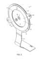
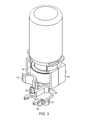
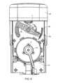
本発明は、流体を取扱い目に流体を送出するための方法および装置に向けられている。図1、2および7を参照すると、流体エジェクタ2(図2)および流体ハンドラ14(図7)を含む装置1が示されている。流体エジェクタ2は、振動素子4に結合された圧電素子15により振動させられる複数の開口部6を有する振動素子4を含む。本明細書中で使用される流体なる用語は、あらゆる流動性物質を意味し、材料の液体状態のみを意味するわけではない。 The present invention is directed to a method and apparatus for handling fluid and delivering fluid to the eye. 1, 2 and 7, a
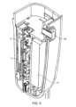
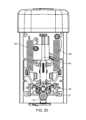
装置1は、捩込みまたはスナップ嵌合などの任意の好適な係合を用いて共に係止する第1のハウジング部分7と第2のハウジング部分9を含み得るハウジング5を有する。図5を参照すると、プリント回路板13を含む制御システム11が第1のハウジング部分7に組付けられている。制御システム11は、当該技術分野において公知の通り圧電素子15に結合されこれを制御する。当該技術分野において公知の通りバッテリ19が制御システム13および圧電素子15のための駆動用電子機器に電力を供給する。流体取扱システム14は、第2のハウジング部分9に結合されている。制御システム11は再利用可能であり得るが、一方流体ハンドラ14は使い捨てであり得る。さらに、流体は、取外しを防止する目的で第1のハウジング7に係止され得る流体コンテナ17内に保持されてよく、こうして流体ハンドラ14は最初の流体コンテナ17の後に(これと共に)廃棄することができる。当然のことながら、流体取扱システム14を、2つ以上のコンテナ17と共に使用することもでき、あるいはコンテナ17は充填されるタンクを有することもでき、これによって本発明の多くの態様から逸脱することは無い。さらに、全システム1は、使い捨て可能または再利用可能であるかまたは、任意の形で使い捨て可能および再利用可能部分へと分割されてもよく、そのために本発明の大部分の態様から逸脱することはない。 The
圧電素子15は、環状ディスク23の開放した中央領域26内に開口部6が位置付けされている状態で振動素子4の送出側8または流体側10のいずれかに結合された環状ディスク23であり得る。圧電素子15は、任意の好適な材料(例えばチタン酸ジルコン酸鉛;化学式Pb[ZrxTi1-x]O3の金属間無機化合物)で製造されていてよい。圧電素子15は当該技術分野において公知の任意の好適な形で振動素子に対し、ボンディング、接着、成形または他の方法で結合され得る。圧電素子15を制御するために、可撓性回路21が圧電素子15と電気的連通状態にある。可撓性回路21は、素子4を振動させるため圧電素子内に振動を誘発し開口部6から流体を駆出するように圧電素子15を制御する制御システム1(図5参照)に結合される。振動素子4は、共振周波数であり得る100~160khzの周波数で振動させられる。共振周波数は、当該技術分野において公知の通りに予備決定、測定、決定または整調され得る。圧電素子15の駆動周波数は、以下でさらに説明される。当然のことながら、動作周波数は、共振周波数以外の周波数であってもよい。The
開口部6における振動素子4の流体側10は、送出すべき流体と接触し、送出側8に流体を駆出する。流体は、振動素子4が振動させられた時点で目に向かって開口部6を通して駆出される。開口部6は、流体側10から送出側8へと先細になっていてよい。例えば、流体側で開口部6は160~240ミクロンの直径を有していてよく(そして200ミクロンであり得る)、一方送出側における直径は20~60ミクロンであってよい(そして40ミクロンであり得る)。一定直径(20~60ミクロン)のカラムが、送出側8まで延在し、10~40ミクロンの長さを有し、長さ約25ミクロンであり得る。開口部6は、流体側と送出側の間に100ミクロンの曲率半径の曲線状の壁を有し得る。流体側10および送出側8において開口部6は、円形断面形状を有していてよい。本明細書中で使用される断面積(または他の寸法)は、同じ面積を有する円についての有効直径(または有効半径)によって定義され得る。 The
振動素子4は、100~180ミクロンまたは120~160ミクロンの厚みを有することができ、約140ミクロンであり得、任意の好適な材料、例えばPEEKまたはポリイミドで製造され、追加の層は銅、ポリイミド、ニッケルおよび/または金で構成されていてよい。振動素子4は、125ミクロンの厚みを有していてよく、コーティング/メッキは、振動素子4が約140ミクロンの厚みを有するように約15ミクロンの合計厚みを有する。当然のことながら、振動素子4および圧電素子15の材料および製造および開口部6の寸法に関して、本発明の範囲内で他の多くの構成を実践することが可能である。 The vibrating
流体は、送出側8で開口部6を離れるにつれて、平均駆出速度が2.5m/s~15m/sであり、約5~6m/sであり得るように、駆出されてよい。振動素子4は、複数の開口部6の駆出配向の幾何学的中心によって画定される複数の開口部6の中央配向である中心軸CAを画定する。平担な振動素子4を伴う均等な密度分布の開口部6の円形パターンについては、中心軸CAは、開口部6の円形パターンの中心で振動素子4の平面に直交して延在する。換言すると、中心軸CAは、振動素子4により画定された平面に直交し、開口部6が整列されている駆出方向の幾何学的中心と、または複数の開口部6によって創出される噴霧パターンの幾何学的中心と整列している。中心軸CAは、本明細書中で使用されているように、例えば開口部6がクラスタ化されているかまたは不規則または非対称の形状または変動する開口部6密度(開口部数/mm2)を有する場合には、本発明の範囲から逸脱することなく平均的なまたは幾何学的な中心によって画定されてよい。The fluid may be ejected as it leaves the
図1、3および7を参照すると、陥凹22がコンテナロック26上の係止用タブ24と係合する場合に、ハウジング5(具体的には第2の部分9)に係止される流体コンテナ17の中に、複数回用量の流体が保管されている。スナップ嵌合コネクタ28(図3)が、以下で説明されるポンプ32のマニホルド30(図7)に対して係止する。コンテナ17が下向きに押されハウジング5に係止されると、流体送出針34が、コンテナ17内の隔壁38などの穿刺可能な要素36を通過する。独立したものであるかまたは流体送出針34と同心的に配設され得る通気針40も同様に、穿刺可能な要素36を通過する。以下でさらに説明されるようなポンプ32を用いて、流体導管42を通ってコンテナ17から流体が引き出される。以下で説明するようにコンテナ17を通気するために使用される吸気管腔27(フィルタ29でカバーされている)の中に空気が引き込まれる。 With reference to FIGS. 1, 3 and 7, fluid is locked into the housing 5 (specifically the second portion 9) when the
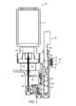
図7~12を参照すると、流体の個別の用量が、エンクロージャ18および振動素子4によって形成されるチャンバ16に送出される。チャンバ16は、流体の送出後実質的に乾燥しており、保管されているときには乾燥状態であることができ、こうして望ましくない汚染または蒸発に悩まされる場合のある「湿潤」システムに比べて有利である可能性がある。エンクロージャ18は、振動素子4の流体側に隣接して位置付けされた唇状部46を伴う壁44を有する。唇状部46は、複数の開口部6の周りに延在する。エンクロージャ18および振動素子4は共にチャンバ16を画定するか、またはチャンバ16は、開放端部33が唇状部46と境を接し唇状部46により画定されている一方でエンクロージャ18の開放端部33と境を接するエンクロージャ18によって画定され得る。壁44は、開放端部33から、主入口52を有するハブ35まで延在する。主入口52は、流体がポンプ32により送出されるときに通る管56の中に形成された管腔54に結合されている。エンクロージャ18は、管56と共に形成されても、図示されている通り別の部品として形成されてもよい。管56は、ポンプ32が流体を直接エンクロージャ18に送出するようにポンプ32の一部として画定され得るマニホルド30を伴って形成されてよい。マニホルド30は、ハウジングと係合する組付け用唇状部31(図22)を有する。管56は同様に、本明細書中で使用されるポンプ32とは別個に画定されてもよく、例えば、管56は(使い捨て可能部分または再利用可能部分のいずれかとして)エンクロージャ18の一部であってよい。 7-12, discrete doses of fluid are delivered into the
エンクロージャ18の唇状部46は、流体が唇状部46と振動素子4の間から漏出または漏洩するのを防ぐため、振動素子4の流体側10に隣接して位置付けされる。唇状部46および振動素子4は、開口部6を取巻き0.190~0.240、恐らくは0.210インチの直径を有する閉ループに沿って互いに隣接している。エンクロージャ18は同様に、エンクロージャ18の開放端部で唇状部46と境を接する部域の幾何学的中心であってかつこの唇状部46と境を接する部域に直交して配向された中心軸CAを画定する。本明細書中で使用されている中心軸CAなる用語は、適用可能な本明細書中の定義のいずれか1つを意味することができ、該当する場合互換性があり、例えば2つが共線的である場合などこの中心軸CAなる用語が使用されるあらゆる場合において、このような置換が明示的に組み入れられる。当然のことながら、エンクロージャ18の中心軸CAおよび振動素子4の中心軸CAは、以下で説明する通りの本発明の範囲から逸脱することなくオフセットおよび/または傾斜している場合があり、独自の定義が具体的に適用される。 The
エンクロージャ18の唇状部46は、唇状部46が振動素子4の振動を妨害しないように、振動素子4から離隔されていてよい。当然のことながら、唇状部46は、表面張力により液体の漏出を防ぐように振動素子4の近くになくてはならない。例えば、唇状部46は250ミクロン未満または125ミクロン未満だけ振動素子4から離隔されていてよい。振動素子4は、最大振幅が接触を防ぐのに充分なほど小さい場合、振動中にエンクロージャ18に触れないですむ。換言すると、唇状部46は、平均250ミクロン未満または平均125ミクロン未満振動素子4から離隔した表面を有し、振動素子4と接触しない少なくとも270度の合計角度範囲にわたり振動素子4から離隔されている。さらに別の言い方をすると、表面は、中心軸CAに沿って見た場合複数の開口部6のおおよそ少なくとも270度にわたり少なくとも125ミクロンの分離距離だけ離隔されている。唇状部46は、流体送出のための振動中でさえ、振動素子4と接触することなく開口部6の全周に延在していてよい。いずれかの側の界面は、本発明の範囲から逸脱することなく、連続的であるよりむしろ中断されていてよい。例えば、唇状部46の表面は、各々20度に広がる4つの小さい区分に沿って振動素子4と接触することができ、こうしてたとえ連続的でない場合でも少なくとも270度に沿って唇状部46が振動素子4と接触しないようになっている。本明細書中で使用されるように、チャンバ16は、流体がエンクロージャ18と振動素子4の間から漏出しないようになっているかぎり、エンクロージャ18と振動素子4によって画定され、チャンバ16は、たとえ完全に取囲まれていなくても、流体保持用空間として画定されるものとする。本明細書中で使用される「唇状部」なる用語は、単に振動素子4に隣接する表面を意味し、いかなる特殊な構造も形状も必要とせず、単純に、壁44の端部または壁44の端部にあるコーティングであってよい。例えば、唇状部46は、フランジ、剛性カップのリムまたは波形表面、起伏あるまたはのこぎり歯形状の表面のようにさらに幅広のものであり得、それにより本明細書中で使用されている「唇状部」の意味から逸脱することはない。流体は、唇状部46が振動素子4から離隔されているとき唇状部46に沿って表面張力によってチャンバ16内に保持され得るものの、先行技術において時として使用されているように、流体の大部分は毛細管補給の特徴を有していない可能性がある。毛細管補給を組み込んでいるこのような先行技術のシステムは、典型的には、振動素子4内の開口部6に直ぐ隣接する流体補給部域に沿ってこれを行なう。以下で説明するように、本発明は、開口部6に対し流体を送出するために毛細管作用が必要とされないかまたは組込まれないように、開口部6に隣接して充分な空間を提供することができる。 The
唇状部46は同様に、振動素子4を過度に拘束せずなおかつ流体を保持しながら、離隔されているのではなくむしろ振動素子4と接触していてもよい。このために、唇状部46は、比較的低い力で振動素子4に対して偏向され得る。例えば、唇状部46により振動素子4に対して及ぼされる力は、エンクロージャ18(および同様に振動素子4)の中心軸CAの方向に測定された場合3グラム重量未満であり得、2グラム重量未満であってもよい。唇状部46は同様に、中心軸CAの方向で最高0.050mmの変位について60gram-f/mm以下、さらには40gram-f/mm以下の平均ばね定数で振動素子4に対して制御されたばね荷重を加えることもできる。制御されたばね定数は、極限温度、圧力および衝撃荷重(落下時)について唇状部46および振動素子4の相互作用に影響を及ぼし得る極限条件下での動作に役立つ。制御されたばね定数は同様に、振動素子4に対し唇状部46が究極的に加える荷重に製造許容誤差が影響を及ぼし得るという点において、製造可能性にも役立ち得る。 The
唇状部46および/または壁44は同様に、唇状部46と振動素子4の間の柔軟な接触のために弾力性ある材料で作られていてよく、エンクロージャ18の弾力性ある材料および幾何形状は、ばね力の応答を発生させるのに寄与し得る。例えば、唇状部46は、60A未満のデュロメータを有する材料で作られてよい。壁44は、チャンバ16を包囲する0.003~0.007インチの厚みを有することができる。エンクロージャ18の弾力性は、唇状部46自体の材料によっておよび/またはタブ、板ばね、コイルばね、片持ち梁、コンテナ17用の弾力性ある組付けまたは他の任意の機構または組合わせを用いて機械的に提供され得る。例えば、エンクロージャ18は、本発明のこの態様にしたがってカップ上に力を加える適切なばねを伴う、リムに沿ってエラストマコーティングを有する剛性カップであり得る。 The
エンクロージャ18の壁44は、一部の事例においては振動素子4との係合の弾力性にも最大限に貢献し得る側壁56を含む。側壁56は、唇状部46からハブ35まで延在し、中心軸CAの周囲で全周にわたり延在する。エンクロージャ18の弾力性は、全体的にまたは部分的に、側壁56の形状によって提供され得る。側壁56は、大端部(直径0.210~0.220インチ)から小端部(直径0.180~0.190インチ)まで延在するテーパ付き部分60を有することができ、ここで大端部は振動素子4に対しより近くに位置付けされ(かつ遠位端部で唇状部46に隣接してよく)、小端部よりも大きい部域を包含する。側壁56のテーパ付き部分60は同様に唇状部46から延在する第1の円錐台状部分62、および第1の円錐台状部分62の小端部からハブ35まで主として半径方向に内向きに延在する半径方向延長部分64をも含み得る。半径方向延長部分64は、エンクロージャ18の中心軸CAとの関係において半径方向内向きに延在する。壁44および側壁56の各部分の配向および相対的寸法は、中心軸CAに沿って見た場合に少なくとも270度の合計角度範囲にわたって(または図示されているように中心軸CAの全周に)(振動素子4および/またはエンクロージャ18の)中心軸CAが上に存在している平面における断面形状を基準にして、本明細書中に説明されている。半径方向延長部分64は、開放端部の相当半径の少なくとも20%、半径方向内向きに延在する。半径方向延長部分64は、中心軸CAが長手方向を表わすものとして中心軸CAとの関係において少なくとも3対1の半径方向変位と長手方向変位の比を有していてよく、中心軸CAに沿って測定した場合に、振動素子4から0.014~0.030インチまたは0.014~0.040インチのところに位置付けされてよい。本明細書中で使用される「相当半径」または「相当直径」なる用語は、同じ面積を有する円の半径または直径を意味する。側壁56のテーパ付き部分60は、半径方向延長部分64からハブ35まで延在する第2の円錐台状部分63を有する。 The
側壁56のテーパ付き部分60は、唇状部46からハブ35まで延在する。合計して、テーパ付き部分60は、中心軸CAとの関係において少なくとも1対3、少なくとも2対3または少なくとも1対1の半径方向変位と長手方向変位の比を有し得る。本明細書中で使用される「テーパ付き」なる語は、漸進的または連続的変化を必要とせず単に補給部域を表わす中心軸CAに対して直交するサイズの縮小を意味するにすぎない。この縮小は段階的であってよく、あるいは、本明細書で使用されている「テーパ付き」の定義から逸脱することなく、半径方向延長部分64のように実質的に半径方向にのみ延在し得る。側壁56のテーパ付き部分60は、中心軸CAに沿って見た場合にエンクロージャ18のおおよそ少なくとも270度にわたり唇状部46の取囲まれた境界の有効半径の少なくとも20%、(エンクロージャ18の中心軸CAとの関係において)半径方向に延在し得る(そして中心軸CAの周囲に完全かつ全体的に延在し得る)。側壁56のテーパ付き部分60は0.003~0.007インチの厚みを有することができ、側壁56の可撓性を増強させるために約0.005インチであり得る。側壁56は、ハブ35まで延在し、噛合するコネクタ(図示せず)を有する管56(図7)の端部と係合するコネクタ66が形成される。管56内に管腔54からの流体を受入れる主入口52はハブ35によって形成される。管56内の管腔54のもう一方の端部は、ポンプ32からの流体を受入れる。 A tapered
唇状部46は、振動素子4となおも接触しながら、振動素子4に対し取付けられていなくてよい。本明細書中で使用される「no attachment(取付具が全くない)」、「not attached(取付けられていない)」、「unattached(取付けられていない)」なる用語は、摩擦接触以外の連結が全く無いことを意味する。換言すると、唇状部46は、中心軸CAに沿って振動素子4から離れるように自由に移動することができる。さらに別の言い方をすると、エンクロージャ18(具体的には唇状部46)は、振動素子4との関係において中心軸CAの方向に一定の自由度を有するように、取付けられていない。したがって、唇状部46および振動素子4は、横方向の動きを抑えることができるものの本明細書中で定義されている「取付具」を構成しない流路および/または隆起したバッフルまたは壁を有していてよい。唇状部46は、唇状部46に対して丸味のある端部を提供するため約0.005インチの曲率半径を伴う曲線状の表面を有することができる。 The
振動素子4および唇状部46は2つの界面において取囲まれた境界41を画定する(ただし、その各々は互いに同じ境界を画定できるという意味において単独で取囲まれた境界41を画定し得る)。取囲まれた境界41は、直径が5.3~5.7mmまたは約5.5mnである取囲まれた補給部域51(図11)を振動素子4の流体側に画定する。振動素子4内の開口部6は、円形で2.6~3.0mmの直径または換言すると3.0mm未満または約2.8mmの直径を有する振動素子4の送出部域39を包含し画定する。当然のことながら、比較のため有効直径または半径と共に、他のパターンおよび円形以外の形状を使用することができる。取囲まれた境界41は、送出部域39が、取囲まれた補給部域51の75%以下または50%以下であり得るという点において、送出部域39よりもかなり大きい可能性がある。換言すると、取囲まれた補給部域51は、送出部域39に比べて少なくとも30%大きい可能性があり、少なくとも100%大きい可能性がある。さらに別の言い方をすると、取囲まれた補給部域51は、余剰の補給部域58(中心軸CAに沿って見た場合に送出部域39と同一の広がりを持たない取囲まれた補給部域51によって画定される)が送出部域39の少なくとも30%となるように送出部域39よりも大きくてよく、さらには、送出部域39よりも大きいまたは最高50%大きいものでさえあり得る。余剰補給部域58は、同心的配設についての環状リングまたはオフセット環状部域(円形ではないものの相当半径または直径を用いる場合円として表わされ比較されるもの)についての三日月形であり得る。振動素子4の送出部域39は、相当面積の円についての幾何学的中心および有効半径を画定する。取囲まれた補給部域51は同様に、相当面積の円についての幾何学的中心および有効半径を画定する。取囲まれた補給部域51の幾何学的中心は、送出部域39の幾何学的中心の上方にあり、送出部域39の有効半径の少なくとも0.3倍だけオフセットされ得る。チャンバ16内に保持された流体は同様に、中心軸CAの方向で測定した場合に振動素子4から0.015未満のところに位置付けされた幾何学的中心も画定する。流体の幾何学的中心は、同様に、オフセット設計についての送出部域39の幾何学的中心の上方、送出部域39の有効半径の少なくとも0.3倍のところに位置付けされ得る。同心的実施形態については、流体(またはチャンバ16の容積)の幾何学的中心は、振動素子4の中心軸CAから送出部域39の有効半径の0.1倍未満のところにある。 The vibrating
エンクロージャ18は、小さい容積をもつ比較小型のチャンバ16を提供するものの、チャンバ16は、一部の先行技術が教示しているように毛細管補給を必要とすることなく、開口部6に流体を提供することができる。エンクロージャ18は、エンクロージャ18により画定されるチャンバ16の境界を画定する内部表面49を有する。流体は、チャンバ16内で内部表面49と接した状態で保持される。エンクロージャ18の内部壁45は、約0.017インチの分離により開口部6から離隔されている開口部6に面する側47を有する。エンクロージャ18の内部表面49と振動素子4の間の間隔は、毛細管作用が存在しないように、毛細管間隔よりも大きくてよい。毛細管補給は、流体を迅速に送出することが所望される場合流体流を妨げる可能性があり、同様に、補給システムから流体を完全に送出するのを困難にし、これは残留流体の問題を提起する。考えられる毛細管作用を回避しかつ/または流れに対する障害物を最低限に抑えるためには、開口部6の少なくとも75%、または少なくとも95%さらには全てがエンクロージャ18の内部表面49の最も近い部分まで少なくとも0.010インチまたは少なくとも0.014インチの最小間隔を有するように、開口部6とエンクロージャ18の最も近い部分の間の間隔を最小限にすることが望ましい可能性がある。 Although the
時には毛細管作用を回避することが望ましい場合があるものの、流体の実質的に全ての迅速な送出を提供することがなおも望ましく、したがって、チャンバ16内の流体が駆出のために開口部6に到達するのに遠々と移動する必要がなくなるようにエンクロージャ18を整形することがなおも可能である。このために、エンクロージャ18の内部表面49は、チャンバ16内の流体と直接流体連通状態にある流体の少なくとも75%、または少なくとも95%さらには全てが、振動素子4内の最も近い開口部6から0.060インチ以下または0.040インチ以下のところにあるように整形され得る。換言すると、チャンバ16は、チャンバ16内の流体の少なくとも75%、95%さらには全て、そして任意にはチャンバ16内の流体と流体連通状態にある全ての流体が、最も近い開口部6に通じる見通し線を有するように、エンクロージャ18の内部表面49によって整形され形成され得る。多くの先行技術システムは、湿潤型補給管または導管を有しており、これらの管または導管は、流体が充填され、開口部6から0.060インチよりもはるかに遠くに離隔されており、かつ残留量に寄与し得る導管内に流体を保持する傾向を有し得る表面張力および他の力を克服しなければならない。したがって、いくつかの事例においては、短かい時間周期内で低い残留量で高速の実質的に完全な送出を行なうため、開口部6に比較的近いところに妨害無く全ての流体をなおも有しながら、毛細管作用を回避するべく、開口部6の全てとは言わないまでも大部分をエンクロージャ18から最小限の距離だけ分離させることが望ましいかもしれない。両方の懸案事項に対処する場合、チャンバ16を形成するエンクロージャ18は、振動素子4の中心軸CAの方向で見て測定した場合に、開口部6の全てから0.014~0.040インチだけ離隔され得る。別の流体と「連通状態にある流体」とは、開口部に対して流体を送出する補給管、パイプ、芯および流路を含む連続した流体を意味する。 While it may sometimes be desirable to avoid capillary action, it is still desirable to provide for rapid ejection of substantially all of the fluid, so that the fluid within
エンクロージャ18は、チャンバ16を画定する一体として形成された構造であり得る。一体として形成された構造は、熱可塑性エラストマ製であり得、射出成形などの好適な方法によって形成され得る。1つの例は、熱可塑性エラストマであるTF5CGNとしてKraiburgにより供給されるThermolast(登録商標)の名称で販売されているものである。
送出される流体の量は、チャンバ16を75~90%だけ満たすことができ、これにより、表面張力の力によって全ての流体がチャンバ16内に集まるよう促す余裕を送出中に提供することができる。エンクロージャ18に対して少なくとも0.5m/s(または少なくとも1.0m/s)の速度で流体を送出することによって同様に、管56から駆出される流体の実質的に全てが、残留物として残されるのではなくむしろチャンバ16内に集まるよう促すことができる。換言すると、ポンプは、多くの流体を目に送出するために所望される速度を達成するのに充分なものであり得る少なくとも200psi(そして恐らくは約300psi)の圧力で流体を送出する。このようにして、少ない流体量が、エンクロージャ18内に発射される単一の流体「液滴」として残留する。 The amount of fluid pumped can fill
エンクロージャ18は、各々チャンバ16に通じる第1の入口55および第2の入口57へと、主入口52からの流れを分割することができる。エンクロージャ18は同様に、第3の入口59および第4の入口61を有することもでき、第1および/または第2の入口55、57の全ての態様は、第3のおよび/または第4の入口59、61について、そして独立して論述されている場合には第1および第2の入口55、57の他方のものについて、明示的に組込まれており、このような特徴および限定は全て、他の入口全てについて明示的に組込まれる。第1の入口55は、振動素子4内の開口部6に向けられる前に側壁56のテーパ付き部分60などのエンクロージャ18の内部表面49に流体を向ける。第1の入口55および第2の入口57は、チャンバ16に直接通じていてよく、入口は両方共、振動素子4内の開口部6に導かれる前に(側壁56に沿った内部表面49などの)エンクロージャ18の内部表面49にチャンバ16に入る流体の全て(またはこの流体の少なくとも90%)を向けるように配向されている。このようにして、チャンバ16の充填中に流体が開口部6を通って強制される可能性を削減することができる。詳細には、本明細書中で示唆されているような速度または圧力でチャンバ16内に流体が強制される場合、このような方法でエンクロージャ18内に流体を導くことが有利であり得る。
主入口52は、当初、分流チャンバ66の一部を成す開口部6と反対側の内部壁45に流体を向ける。内部壁45は、中心軸CAとの関係において側壁56の一方の側から他方の側まで延在して入口を形成する。分流チャンバ66は流れを、各々側壁56のテーパ付き部分60から離隔されこのテーパ付き部分60に向けられた4つの入口を通過する4つの細流へと分割する。分流チャンバ66は、図示されているようにチャンバ16に直接通じていてよく、または、追加のバッフルまたは流れ変更機能を有することができる。主入口52は流れを、エンクロージャ18の中心軸CAから30度以下の方向に導き、図示されている通り中心軸CAに沿っているかまたはこの中心軸と整列していてよい。第1の入口55および第2の入口57は、流体が開口部6に向けられるのを回避するため中心軸CAに直交して中心軸CAから30度の範囲内で流体を導くように配向されてよい。エンクロージャ18は、同様にエンクロージャ18の側壁56において配向されている第3の入口および第4の入口を有することができる。エンクロージャ18の中心軸CAに沿って見た場合、隣接する入口は互いから60~120度配向され、図示されているように隣接する入口55、57、59、61から約90度のところにあり得る。 The
分流チャンバ66は、凹側70が振動素子4に向かって面している状態で(内部壁45を含む)カップ状の壁68を有する。カップ状の壁68は、内部に形成された4つの入口全てを有する。カップ状の壁68は、唇状部46の中心軸CAとの関係において少なくとも240度の角度範囲について唇状部46により画定された有効半径の少なくとも25%にわたりエンクロージャ18の中心軸CAから半径方向外向きに延在する。第1の入口55は、中心軸CAとの関係における半径方向寸法および長手方向寸法を有し、半径方向寸法対長手方向寸法の比は0.5対1.5である。第1の入口55および第2の入口57は、中心軸CAの方向で見た場合、主入口52の一部を露呈するため中心軸に向かって半径方向内向きに延在するが、主入口52から振動素子4までの直接的長手方向流は、カップ68の底部を形成する内部壁により半径方向外向きに導かれる流体の大部分によって創出された流れに対する半径方向成分により防止される。 The
チャンバ16は同様に、チャンバ16の寸法と共に、流体のいずれかの残留部分が分流チャンバ66内に残留するかまたはチャンバ16と分流チャンバ66の間に延在するのではなくむしろチャンバ16内に流体が集まるように促すためのより低いエネルギ状態を提供する少なくとも2つ、3つまたは4つの入口55、57、59、61が提供されるように形成される。本発明の多くの態様が残留流体の最少化に向けられているものの、本発明は、幾分かの残留量が残されている状態で実践され得、実際、本発明のいくつかの態様は、本発明のこれらの態様から逸脱することなく、湿潤型システムで使用することができる。 The
流体がチャンバ16から排出される(開口部6を通って駆出される)につれて、動作中にチャンバ16を通気するために補充空気を導入しなければならない。エンクロージャ18は、唇状部46が振動中に流体を解放することなく空気をエンクロージャ18内に通気するために充分なほど振動素子4から分離している状態で、唇状部46と振動素子4の間でエンクロージャ18内に空気を通気することができる。唇状部46と振動素子の間に通気される空気は、開口部6に向かって半径方向内向きに半径方向外側の領域において流体を移動または変化させることによって、および、半径方向外側の空間(余剰の補給空間)を占有する可能性のある残留流体の代わりにこの空間を単に占有することによって、流体送出に役立つことができる。 As fluid is discharged from chamber 16 (ejected through opening 6), make-up air must be introduced to vent
流体が開口部6を通って駆出されるにつれてエンクロージャ18を通気するために、振動素子4のいくつかの開口部6内に空気を引き込むことも同様に可能である。空気は、ある意味「活動状態の」駆出開口部6を見い出すべく流体を間に分配することのできる小さな泡としてチャンバ16内に導入される。エンクロージャ18は、他の通気開口部も専用通気口も全く含まなくてよく、これによりシステムは単純化され考えられる汚染経路または汚染源が無くなる。当然のことながら、ここで説明されている本発明から逸脱することなく、チャンバ16のために専用通気口を具備することも可能である。 It is likewise possible to draw air into some of the
図32~35を参照すると、チャンバ16およびエンクロージャ18と実質的に同じである別のチャンバ16Aおよびエンクロージャ18Aが示されており、チャンバ16およびエンクロージャ18(本明細書中で説明されている全ての他のエンクロージャおよびチャンバ)に関連する全ての用途および組合せおよび他の全ての開示がここに組込まれている。同様にして、チャンバ16Aおよびエンクロージャ18Aについての全ての論述が同様にチャンバ16およびエンクロージャ18(および他の全て)のためにも組込まれる。エンクロージャ18Aは、振動素子4に隣接する唇状部46Aを伴う壁44Aを有する(図2参照)。動作中チャンバ16Aを通気するため、壁44Aの中に壁開口部124が形成されている。壁開口部124は同様に、以下で説明する通りエンクロージャ18の可撓性を増強する寸法を有することができる。唇状部46Aは、間の摩擦を削減するため振動素子4に隣接してPTFEコーティング120を有することができる。振動素子4も同様に、間の摩擦を削減するために唇状部46に隣接してPTFEコーティング122を有することができる。コーティング120、122は、中心軸CAに沿って見た場合おおよそ少なくとも270度にわたり延在することができる。当然のことながら、コーティング122は中心軸CAの全周に延在していてもよい。エンクロージャ16、16Aの内側表面123は、送出に先立って装填された流体と接触するエンクロージャ18Aの内側表面123の少なくとも70%にわたり疎水性であり得る(コーティングされているかまたは材料の特性による)。 Referring to FIGS. 32-35, another
壁開口部124は、くさび形の開口部などの任意の好適な形状をとることができる。壁開口部124は、壁44A、具体的には壁44Aの側壁56Aを貫通して延在してチャンバ16Aを露呈する。壁開口部124は同様に、唇状部46A内に小さい間隙131を形成し、これは、開口部124の幾何形状と共に、流体の漏洩を防ぐのに充分小さいものであるが、それでもなお、流体が駆出されるときに空気が流入できるようにすることによってエンクロージャ18Aを通気するのに充分な大きさを有することができる。エンクロージャ18の通気に関する全ての論述および応用、例えば唇状部14と振動素子4の間の通気、唇状部と振動素子の間の間隔および力-変位特性についての論述がここに組込まれている。したがって、唇状部14Aは、本明細書中で説明されているいずれかの形で振動素子4から離隔されるかまたはそれと接触していてよい。 Wall opening 124 can take any suitable shape, such as a wedge-shaped opening. Wall opening 124 extends through
壁開口部124は、中心軸CAの方向で唇状部46から測定される長手方向寸法126および中心軸CAとの関係において半径方向に測定される半径方向寸法128を有する。壁開口部124の長手方向寸法126は、振動素子4と開口部6に面するエンクロージャ18Aの側47Aとの間の分離125の少なくとも80%であり、図示されているように実質的に全長に延在していてよい。壁開口部124の半径方向寸法128は、唇状部46Aの相当円周の10%以下または5%以下である。半径方向寸法128は、約0.025インチであり得、一方長手方向寸法126は約0.022インチであり得る。エンクロージャ18A、壁124Aおよびチャンバ16Aの寸法は、全て本明細書中に組込まれているエンクロージャ18および全ての幾何学的関係と結び付けられた寸法を含めた任意の好適な寸法であり得る。 Wall opening 124 has a
壁開口部124は、唇状部46Aから近位に延在し、その位置および形状に起因してエンクロージャ18Aの可撓性を増大させることができる。壁開口部124は、中心軸CAとの関係において円周方向的に測定された円周方向寸法130を有する。円周方向寸法130は、唇状部46Aにおいて約0.012インチであり得(間隙131と同じ)、2つの側が壁開口部124の近位端部132において収束するように先細になっている。円周方向寸法130は、本明細書中、中心軸CAの半径方向配向に直交する線分についての測定値として定義される。壁開口部124は、壁開口部124が唇状部46Aから近位に延在するにつれて先細になる。壁開口部124は、壁開口部124のテーパ付き形状132がチャンバへの入口55、57、59、61のうちの少なくとも1つの方向に配向され(「それを指す」)かつ中心軸CAに沿って見た場合に2つの入口と整列するように配向され得るように先細になっている。このような形で壁開口部124のテーパ付き形状132を入口55、57と配向させることにより、入口と壁開口部124がその幾何学的整列のため協働して可撓性を増大させることから、可撓性は増大する。テーパ付き開口部の「配向」とは、壁開口部124から離れるように延在するテーパ付き角度の2等分として定義されるものとする。テーパ付き形状132は同様に、中心軸CAとの関係において10度の半径方向配向内にあり、図示されている通りに実質的に半径方向に配向されていてよい。壁開口部124は同様に、円錐台状部分62Aの長さの少なくとも80%にわたり唇状部から近位に延在している状態で、円錐台状部分62Aに沿って位置付けされている。 Wall opening 124 extends proximally from
ここでポンプ32についてさらに詳述する。ポンプ32は、流体コンテナ17から個別の量を引き出し、これらの量をチャンバ16に送出する。流体コンテナ17は、いくつかの利用分野において、流体コンテナ17と結び付けられたピストン/プランジャなどの好適な他の任意の機構であり得る。流体コンテナ17は、多重回用量装置についてのチャンバ16の容積(または送出される流体の量)の少なくとも150倍である流体担持能力を有していてよい。ポンプ32は、毎回同じ(そして任意には唯一の)量を送出するように構成され得る。当然のことながら、本発明の事実上全ての態様から逸脱することなく、可変容積型ポンプ32も使用することができる。 Here, the
本発明は、実質的に送出された全用量を用いて単回用量送出を提供し、チャンバ16内にほとんど残留流体を残さないようにするために使用され得る。振動素子4は、チャンバ16の全容積の5%以下、または2%以下しか残留流体(先行する流体送出由来のもの)によって占有されないように、または1マイクロリットル未満しか残らないように、エンクロージャ18から流体を送出することができる。換言すると、振動素子は、流体が駆出された後でかつ流体駆出のための単回起動の後チャンバ16内に流体量の5%以下または2%以下(または1マイクロリットル未満)しか残らないように開口部6と連通状態にある流体の実質的に全量を分配するように動作させられる。このようにして、チャンバ16は、流体の単一回の適用(単回発射起動)の後、実質的に空になる。他の流体送出システムに比べた本発明のいくつかの態様の1つの利点は、複数の活動化間でチャンバ16を残留流体が全く無く実質的に乾燥した状態に残すためほぼ完全に送出される単回用量をチャンバ16が受入れるという点にある。複数の使用間で振動素子4と接触した状態に流体を維持するかまたは不完全な形でしか送出しない「湿潤式」システムに比べて、流体の汚染および劣化を削減することが可能である。 The present invention may be used to provide single dose delivery with substantially the entire dose delivered, leaving little residual fluid within
エンクロージャ18は、それが上述の通り流体により少なくとも70~95%を満たすことができ、こうして流体が単一の液滴としてチャンバ16内に集まるのを助けることができるように、サイズ決定され得る。チャンバ16は、14マイクロリットル未満または10~14マイクロリットルなどの比較的小さい容積を画定することができる。流体量は7~12マイクロリットルまたは10~12マイクロリットルであり得る。管56内の管腔54は、主入口52を通ってエンクロージャ18まで流体を送出し、ここで主入口52の直径は0.040~0.060、恐らくは約0.054インチである。分流チャンバ66は、約0.054インチという主入口52に本質的に整合する直径を有していてよい。管56は、主入口52から延在し、2マイクロリットル未満の容積を有してさらに残留流体を最小限に抑えていてよい。管56は、エンクロージャ18の一部であってよく、別個の部品としてではなくむしろ、エンクロージャ18と共に形成され得る。
使用中、目への流体送出は同様に比較的高速であって、送出中の瞬目による干渉の尤度を低減することができる。流体送出には、200ms未満、さらには150ms未満、または100ms未満しかかからない可能性がある。振動素子4は同様に、単回起動中で複数の振動周期の間に1回の休止を伴って動作させられてもよい。例えば、振動素子は、圧電素子15により約26msの第1の動作周期にわたり駆動され、約3.65msの休止を置いて、その後約26msの第2の動作周期にわたり駆動され得る。振動素子4は、圧電素子15によって、2回の休止を置いて駆動されてよく、ここでこの圧電素子15は、第1の時間周期、第2の時間周期および第3の時間周期の間付勢または活動化され、振動素子4の振動を駆動するにあたって第1および第2の周期は第1の休止によって分離され、第2と第3の周期は第2の休止によって分離されている。振動を駆動するにあたっての第1および第2の休止は、0.5ms~4.0msであり得る。第1、第2および第3の時間周期の各々は、20~40msであり得、全体的送出時間は150ms未満、さらには100ms未満であり得、約85.3msであり得る。第1、第2および第3の振動周期の各々はさらに、約816usの活動化周期に細分化され得、圧電素子15については約586usの間非活動化されてよい。非活動化時間中、振動素子4は、圧電素子15によって能動的に駆動されてはいないものの振動し流体を駆出し続けることができる。同様にして、圧電素子15の各活動化休止中も、振動素子4は流体を駆出し続けることができる。「休止」は、合計時間の少なくとも2%の連続的非活動化として定義され得、複数の休止の合計休止時間は合計送出時間の少なくとも6%であり、約8.5%であり得る。休止が少なくとも2%の時間連続的であるのに対して、非活動化時間はより短かくかつ合計送出時間の0.5~1.0%の連続した時間として定義され得、非活動化時間の合計は合計送出時間の少なくとも30%であるという点において、非活動時間は、休止とは区別して定義される。換言すると、非活動化時間は、第1の時間周期の(そして第2および第3の時間周期も同じ)2.0~2.5%の連続的時間であり、合計非活動化時間は第1の時間周期の少なくとも30%である。当然のことながら、送出時間は、本発明を例示するために定義されており、活動化の時間およびパターンは、駆出される流体の表面張力に応じて変化し得る。 During use, fluid delivery to the eye can also be relatively fast, reducing the likelihood of blink interference during delivery. Fluid delivery may take less than 200ms, even less than 150ms, or even less than 100ms. The
上述のように、圧電素子15を活動化しその後振動素子4を振動させるために使用される交流信号の周波数は、100kHz~160kHzの駆動周波数で誘導される。さらに、周波数は、単回送出中複数の活動化の各々についての駆動周波数(100kHz~160kHzの範囲)を中心とした無作為周波数として制御システム11によって選択され、少なくとも20そして恐らくは少なくとも40回無作為化され得る。換言すると、振動周波数は、圧電素子15が、送出時間(平均)の3%以下にわたり1つの周波数で駆動されてから変更さるように、単回発射起動のために平均少なくとも33回(駆動周波数を中心にして無作為に)変更される。駆動信号の無作為化のカオス的性質が、流体の駆出に役立つ可能性があると考えられている。無作為性は、中心の動作周波数に適用される既定の無作為化された1組の値、または制御システム11によって一意的に生成される無作為値によって提供され得る。 As mentioned above, the frequency of the alternating current signal used to activate the
振動素子4は同様に、比較的低い最大振幅で振動するように設計されてよい。例えば振動素子4は、2ミクロン未満、1.5ミクロン未満または0.5~1.5ミクロン、0.8~1.2ミクロンの範囲内、または約0.8ミクロンの最大振幅で振動することができる。振動素子4の最大振幅は同様に、振動素子4内の開口部6のサイズに比べて比較的小さいものであり得る。例えば、最大振幅は、送出側で開口部6の断面形状の有効直径の5%以下または3%以下であり得る。例えば、最大振幅が1.0ミクロンであり送出側における開口部6の平均直径が40ミクロンである場合、最大振幅は平均直径の2.5%または駆出された流体液滴の平均直径の約2.5%に過ぎない。最大振幅は同様に、例えば(流体側から送出側まで測定した場合)振動素子4の厚みの5.0%以下さらには3.0%以下といったような、厚みに比べて比較的小さい量を表わす。本明細書中で使用される厚みとは、開口部6と境を接する部域についての平均厚みであり得る。低振幅での動作は同様に、低い変位を有する開口部6のいくつかを通って空気を吸込むことができるという点において、開口部6を通しての通気に寄与することもできる。低振幅での動作は同様に、唇状部46と振動素子4の間の流体の封じ込めを維持する一助ともなり得る。唇状部46が振動素子4から離隔している場合、唇状部46は、振動中の振動素子4の最大振幅よりも大きい平均距離だけ離隔されていてよい。換言すると、最大振幅は、唇状部46の表面と振動素子4の間の平均分離距離よりも小さい。 The vibrating
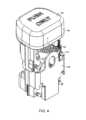
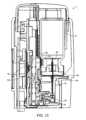
図13~17を参照すると、ポンプ32を露呈するためにハウジングが部分的に取外されている。ポンプ32は、管56内の管腔54を通しておよび主入口52を通して流体コンテナ17からチャンバ16まで流体を送出する(図12参照)。流体コンテナ17は、本発明の範囲から逸脱することなく充填されるバイアル、アンプル、バッグ、ブラダまたは固定型コンテナなどの任意の好適なコンテナであり得る。同様にして、ポンプ32は、本発明のさまざまな態様から逸脱することなく、エンクロージャ18に流体を送出するための任意の好適な機構であり得る。流体コンテナ17は、送出針34および通気針40によって穿孔される穿孔可能なキャップ70を有する。送出針34は、送出流路の一部を画定し、通気針40は通気経路の一部を画定する。送出流路は、ポンプ32まで、およびポンプ32から管56および主入口52を通ってチャンバ16内に延在する。図3および13を参照すると、送出針34および通気針40は、コンテナ17が上に組付けられているコンテナ支持体70に対し組付けられている。コンテナ支持体70は、マニホルド30と係合するカップリング72を有する。通気管腔73が一方向弁76、例えば傘形弁78を含み、これが流体コンテナ17内への空気の流入を許容して、以下で説明するように失なわれた流体量を補充する。 13-17, the housing has been partially removed to expose
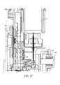
ポンプ32は第1の部分80と第2の部分82を有する。第1の部分80は、保管位置(図13)から部分的行程位置(図14)までそして、最大変位での順方向行程位置(図15)まで往復運動する。第1の部分80は、保管位置まで戻って、一定量の流体をチャンバに送出する1サイクルを完了する。第2の部分82も同様に、保管位置から最大変位での順方向行程位置まで、そして各サイクル毎に保管位置まで戻るように往復運動する。第1の部分80は、主本体86から延在する延長部分84を有する。主本体86は、第2の部分82の主本体89の端部90に面する端部88を有する。第1の部分80上の延長部分84は、第2の部分82の主本体89から延在する延長部分85に向かって延在しこの延長部分85とインタロックする。第1の部分80は、各サイクルを通して、主本体86、89の端部88、90および/または延長部分84、85の互いの係合によって駆動され、次に第1の部分は第2の部分82を駆動する。キャビティ92が第1の部分80と第2の部分82の間で形成され、ここでキャビティ92のサイズは、第1および第2の部分80、82が互いに向かっておよび互いから離れるように移動するにつれて変化する。キャビティ92は、第1および第2の部分80、82が互いに離れるように移動したときにサイズが増大し、こうして順方向行程中キャビティ92内に流体が引き込まれる。第1および第2の部分80、82が互いに向かって移動したときキャビティ92のサイズは減少し、こうして戻り行程中にキャビティ92からチャンバ16まで流体が送出される。キャビティ92は、7~12マイクロリットルであり得る送出中の流体の量と等しい容積を有する。
流体は、第1の部分80の順方向行程中にキャビティ92内に引き込まれる。第1の部分80および第2の部分82は、図13の保管位置から図14の部分的順方向行程位置まで、そして最終的に図15の完全順方向行程位置まで移動可能である。第1および第2の部分80、82は、完全行程位置まで移動し、ここで第1の部分80は、互いに係合するインタロック延長部分84、85によって上向きに第2の部分82を引張る。完全順方向行程位置において、ポンプ32は、いつでも管56を通ってエンクロージャ18内に流体を送出できる状態にある。 Fluid is drawn into
第1および第2の部分80、82が戻り行程中に図16の部分的行程位置に達した時点で、流体はすでにキャビティ92からチャンバ16まで送出されている。第1および第2の部分80、82は、図17の部分的リセット位置まで、そして再び図13の完全リセット位置まで移動することによって、サイクルを完了する。追加の任意のステップは、別個の変位媒体を用いてチャンバ16の下流側に残されたあらゆる流体をパージすることであり得る。管56、チャンバ16および分流チャンバ66は、流体の送出に先立ち実質的に流体を含まない合計下流側容積を表わす。ポンプ32により送出される流体量は、流体がチャンバ16に送出された時点で管56および分流チャンバ66が実質的に空になることができるように、合計下流側容積の40~70%であり得る。上述のように流体は、チャンバ16内に液滴を「発射する」ために少なくとも0.5m/sという比較的高い速度で(または少なくとも200psiの圧力で流体を送出するポンプを用いて)駆出され得、これによって表面張力の力が少量の流体を一緒に集め保持することができる。 By the time the first and
ポンプ32は同様に、失なわれた流体量を補充するための補充空気をコンテナ17内に送出することができる。ポンプ32は、順方向行程中に補充チャンバ94内に空気を引き込み、補充チャンバ94から流体コンテナ17に向かって空気を強制し、こうして戻り行程中空気は流体コンテナ17内に入りこの流体コンテナ17を通気することになる。第1および第2の部分80、82は各々、互いに対面してキャビティ92を形成する端部88、89と反対側に位置付けされた相対する端部97を有する。第1および第2の部分80、82の相対する端部97のうちの少なくとも1つは、全サイクルを通した移動が同様に順方向行程中は補充チャンバ94内に空気を引き込みかつ戻り行程中は空気を吐出するように、補充チャンバ94の一部を形成することができる(例えば第2の部分82の相対する端部97など)。失なわれた(送出された)流体量を補充するために、一方弁76を通して、通気針40を通して、コンテナ17内へ空気が強制される。第1および第2の部分80、82が完全にリセット位置に達した時点で、補充空気はすでに送出されており、ポンプ32は再び保管位置にあり、ポンプ32の第1の部分80がエンクロージャ18への主入口52を遮断する。第1および第2の部分とマニホルドの間および通気および流体送出経路に沿って接合部および空間を封止するために、Oリングが使用される。
図4、6および18~23を併せて参照すると、ポンプ32用の駆動機構が示されている。駆動機構は、レバー98の第1の側96に結合された第1のアクチュエータ94(ボタン95であり得る)を含む。レバー98は、ボタンが下向きに移動するにつれて矢印Aの方向に枢動点Pを中心にして回転する。レバー98の第2の側100は、ポンプ32の第1の部分80の支持プレート102に結合され、こうして第1の部分80は、図18および21の保管位置から、流体がすでにキャビティ92内に引き込まれている図19、20および22の順方向行程位置まで、レバー98の第1の側96と共に上向きに移動するようになっている。レバー98は、レバーアーム長の差に起因して約11/6の機械利得を提供することができる。当然のことながら、他の態様から逸脱することなく、バッテリ19を用いた動力付きシステムを用いて流体を移動させることもできる。必要な下向きの変位(完全順方向行程)に達するまでボタン95が押され続けている間の逆走行をラチェット104が防止し、この下向き変位の時点でラチェット104が解除されて戻り行程を可能にする。 4, 6 and 18-23, a drive mechanism for
第1のアクチュエータ94(例えばボタン)は同様に、順方向行程中にポンプ戻しばね95を負荷する(しかも、2つのポンプばね95を負荷することができる)。負荷されたポンプ戻しばね95は、戻り行程中にポンプ32をデフォルト位置つまり保管位置に戻るように駆動する。ポンプ戻しばね95は、第1のアクチュエータ94、レバーまたはポンプ自体32の一部、例えば図示されている第1の部分80に直接作用することができる。第1のアクチュエータ94(ボタン95)も同様に、保管位置まで戻される。保管位置で、第1の部分80の主本体は管56内の管腔54を通る流れを遮断し、第2の部分82の主本体は、通気経路および流体送出経路を遮断する。この意味において、ポンプ32は、バルブ104のような挙動を示し、本発明のさまざまな態様から逸脱することなく、専用バルブが管56に対して管腔54を閉鎖し、別の方法で流体が移動させられる状態で、本発明を実施することが可能である。 The first actuator 94 (eg, a button) similarly loads the pump return spring 95 (and can load two pump springs 95) during the forward stroke. The loaded
図25~31を参照すると、装置1は同様に、流体が送出されるときに通るアパーチャ107を有するシャッタ105も含んでいる。シャッタ105は、保管位置において振動素子4を遮断しカバーし、シャッタ105の位置(特にシャッタ105の丸で囲まれた部域)を検出するために位置センサ110を使用するとき「オフ」スイッチとして役立ち得る(または「オフ」条件を画定する)。第1のアクチュエータ94が順方向行程を通して移動させられるにつれて、シャッタばね109も同様に負荷される。ポンプ戻しばね95とは異なり、シャッタばね109は、図26の負荷位置で係止される。(光学センサ、電磁センサ、電気センサまたは機械式センサであり得る)位置センサ110は、アパーチャ107が流体開口部6と整列されている発射位置にシャッタ105があるとき、そのことを決定する。例えばセンサ110は、シャッタ上のマーカを検知する制御ユニット11(および再利用可能な第2のハウジング)に結合された光学センサであり得る。シャッタ105が流体の送出を遮断している(またはすぐに遮断する予定である)ことを位置センサが決定した時点で、流体駆出が防止される。流体は、シャッタ105が図26の位置にあり、装置が流体送出準備のできた状態にあるときに係止解除される第2のアクチュエータ106(これは発射または用量ボタン108であり得る)の起動時点で送出される。以下で説明するように使用中、発射ボタン108はシャッタ105を機械的に解放し、流体エジェクタは、位置センサ110によって決定されるようにシャッタ105内のアパーチャが振動素子4内の開口部6と整列される一方で、制御システム11によって活動化される。 Referring to Figures 25-31, the
ここでシャッタ105の運動についてより詳細に説明する。図4、18および23を参照すると、シャッタ105は、保管位置にある。シャッタ105は、タブ109がスロット111内を下向きに滑動し、図19および26の準備完了状態に係止されるように、第1のアクチュエータ94により下向きに移動させられる。装置はここで、用量が装填された時点でのスイッチ(図示せず)の活動化により「オン」状態にある。シャッタ係止状態の間に、装置が流体を装填して用量をいつでも分配できる状態にあることを別のセンサ(図示せず)が決定する場合がある。用量ボタン108の活動化およびそれに続くシャッタ105の位置の位置センサ110による決定に応じた活動化および非活動化は、用量/駆出を引外し終結する機序である。当然のことながら、他の多くの送出タイミング方法を使用することができ、さらに、シャッタ105の動作とは独立した形で流体を送出することが可能である。 The movement of the
傾斜路119を有する解放スロット117内をシャッタ105上のタブ109が上向きに移動するように、図27の位置まで発射ボタン108によってシャッタロック115が変位させられる。発射ボタン108は、シャッタロック115と係合する一対のフック123を有する弾力性アーム121に組付けられており、一部にはアーム121の弾力性に起因してシャッタロック115を保管位置まで引き戻す。ボタン戻しばね125(図17参照)が起動時点で圧縮され、ボタン108を準備完了状態に戻し、同様にシャッタロック115を保管位置に戻すのにも役立ち得る。
流体の用量を取扱いかつ送出するための装置の使用についてここで説明する。流体コンテナ17は使用前に組付けられてよく、あるいは予め装填されているかまたは先行する使用時点から装填されてもよい。初めて(そして任意には唯一回のみ)流体コンテナ17を装填する場合、流体コンテナ17はキャビティ92内に組付けられ、ボタンは流体コンテナ17の上に設置される。ユーザは次に、第1のアクチュエータ94を押圧してコンテナ17を下向きに強制し、通気針40および送出針34が図7に示された通りに流体コンテナを穿孔するようにする。流体コンテナ17は、流体コンテナ17の取外しおよび交換を防ぐため係止可能である。装置はこの状態で保管可能である。 The use of the device for handling and delivering doses of fluid will now be described. The
用量を送出する決定の直前に、チャンバ16内に流体を装填するために全サイクルを通してポンプ32を移動させる第1のアクチュエータ94(キャップ)を起動させる(押圧する)ことによって、チャンバ16に流体が送出される。アクチュエータ94がひとたびデフォルト位置に戻されたならば、流体はチャンバ16内に格納され、いつでも送出できる状態となる。第1のアクチュエータ94は、本発明の多くの態様から逸脱することなく、ボタン95、レバー、スライダ、ツイストノブまたは他の任意の好適な機械式または電気機械式アクチュエータなどの任意の好適なアクチュエータであり得る。当然のことながら、流体は、本発明の事実上全ての態様から逸脱することなく、目に対する流体の送出中かまたは連続的プロセスの直前およびその最中に、チャンバ16に対し送出されてよい。チャンバ16に対する流体の送出後、装置は同様に管56から流体を取り除くこともできる。例えば、ポンプ32は、一定量の変位媒体を引き出し、この変位媒体を管56内に送出して、管56内の全ての流体を送出に先立ちエンクロージャ18内へ変位させることができる。 Immediately prior to the decision to deliver a dose, the
ユーザが準備完了状態となった時点で、ユーザは次に、発射ボタン108を起動させて、流体を目に送出する。装置を照準し整列させるために、ユーザは、装置を目に隣接して位置付け、シャッタ105内のアパーチャ107を通して装置をのぞき込み、振動素子4を見る。ライトチューブ116などの発光素子114が振動素子4などの装置の一部分を照らして、装置を視覚的に照準し整列させる。当然のことながら、他の任意の好適な照準/整列方法も使用可能である。装置がひとたび適正に照準されたならば、発射ボタン108が起動されて、流体を目に送出する。第2の起動は同じアクチュエータまたは異なるアクチュエータ、例えば発射ボタン108であり得る。本発明は、2段階起動プロセスを用いて説明されてきたが、チャンバ16に流体を送出し次に、例えばまぶたと眼球を光学的に区別することなどによって流体を送出するのに適切な時間を決定する単回起動へと2つのステップを組合せることも可能である。装置は、流体の実質的に全てを送出し、単回起動および目に対する単回用量または数量の送出の後、装置はいつでも保管できる状態となる。 Once the user is ready, the user then activates the
請求されている方法および装置の全ての態様は、他の方法および装置に適用され得、このようなクレームの組合せが明示的に組込まれる。さらに、たとえ具体的組合せが先に明示的に請求されていなくても、サイズ範囲、比率、角度的または線形的カバレッジ、百分率または他の任意の数量も、クレーム中に明示的に組込まれる。例えば、他の数量と組合された1つの数量について使用または置換され得るさまざまな値を記述するために、代替的範囲75%、95%および「全て」が使用される。「第1の」および「第2の」なる用語は、自然順序の用語として使用されておらず単に他方から一方を区別するためだけに使用されていることから、クレーム中において互換性があるものとする。さらに、クレーム用語「have(有する)」「having(有する)」、「includes(含む)」、「including(含む)」、「comprises(含む)」および「comprising(含む)」(およびこれらの用語の他の全ての形態、例えば「has」)は、「A has B」または「A includes B」が、AがBを含むものの他の要素または方法制限をも含み得ることを意味するという点において、本明細書中で使用される通り非限定である。最後に、本発明は、量が少なく送出時間が速いことに直接起因して定量化するのが困難であるいくつかの態様、利点または動作条件に関連して説明されてきた。したがって、直接的な観察および測定は、時として実行不可能であるが、定性的情報が主張の一部を裏付けている。例えば、エンクロージャ18の外側の振動素子4と唇状部46の界面にある水は流体が駆出される時にエンクロージャ18に引き込まれることが観察されてきており、これは、空気もまた吸込まれる可能性があるということを標示している。さらに、流体は、専用の通気開口部が全く無い状態でも円滑に駆出される。 All aspects of the claimed methods and apparatus may be applied to other methods and apparatus, and combinations of such claims are expressly incorporated. Additionally, size ranges, proportions, angular or linear coverage, percentages, or any other quantities are also expressly incorporated into the claims, even if the specific combinations are not explicitly claimed above. For example, the alternative ranges 75%, 95%, and "all" are used to describe various values that may be used or substituted for one quantity in combination with other quantities. The terms "first" and "second" are interchangeable in the claims because they are not used as terms of natural order but merely to distinguish one from the other. shall be. Further, the claim terms "have," "having," "includes," "including," "comprises," and "comprising" (and All other forms, such as "has"), in that "A has B" or "A includes B" mean that A includes B but may also include other elements or method limitations. As used herein, non-limiting. Finally, the present invention has been described in connection with certain aspects, advantages or operating conditions that are difficult to quantify due directly to low volumes and fast delivery times. Therefore, although direct observation and measurement are sometimes impractical, qualitative information supports some of the claims. For example, it has been observed that water at the interface between the vibrating
本発明は、好ましい実施形態に関連して説明されてきたが、本発明の特徴および態様か
ら逸脱することなく、さまざまな修正を加えることが可能である。例えば、ポンプ32は
シリンジであってよく、エンクロージャ18は剛性ドームであってもよいし、或いはエン
クロージャ18は振動素子4に取付けられてよく、そのために本発明の態様から逸脱する
ことはない。
本願は、以下の発明を包含する。
[1]
目に一定量の流体を送出するための装置において:
ハウジングと;
前記ハウジングに結合された流体エジェクタであって、複数の開口部を伴う振動素子を有し、該振動素子が流体側と送出側とを有し、前記複数の開口部が前記流体側から前記送出側まで延在している、前記振動素子が振動させられた時点で前記複数の開口部を通って前記流体側から前記送出側まで流体を駆出する流体エジェクタと;
を含む装置。
[2]
前記振動素子の前記流体側に隣接して位置付けされ、前記振動素子と共にチャンバを形成するエンクロージャ、
をさらに含み、
前記エンクロージャが、前記振動素子の前記流体側に隣接して位置付けされた唇状部を有する壁を含み、前記唇状部は前記複数の開口部の周囲に延在し、前記エンクロージャと前記振動素子が共に、送出されるべき一定量の流体を保持するチャンバを画定している、前記[1]に記載の装置。
[3]
前記エンクロージャおよび前記振動素子により形成された前記チャンバに対して流動的に結合された出口を有するポンプと;
前記ポンプに対して作動的に結合された第1のアクチュエータであって、前記第1のアクチュエータの起動が前記ポンプを活動化して、前記チャンバに前記流体量を送出させる、第1のアクチュエータと;
をさらに含む、前記[2]に記載の装置。
[4]
前記振動素子に作動的に結合された第2のアクチュエータをさらに含み、前記第2のアクチュエータの起動が、前記振動素子を振動させ、前記複数の開口部を通って前記流体を駆出させる、前記[1]に記載の装置。
[5]
前記流体量が単回用量で送出される場合、前記エンクロージャによって画定された前記チャンバが前記振動素子の起動前に実質的に空であり、前記振動素子の起動後にも実質的に空である、前記[2]に記載の装置。
[6]
前記エンクロージャが、前記振動素子の単回起動後に前記量の5%以下を有するように構成されている、前記[2]に記載の装置。
[7]
前記エンクロージャは、前記単回起動後に前記チャンバが実質的に空になるように、前記量の2%以下を有するように構成されている、前記[2]に記載の装置。
[8]
前記エンクロージャは、前記単回起動が完了した時点以前には前記チャンバが実質的に空であるように、残留流体として1マイクロリットル以下の流体量を有するように構成されている、前記[2]に記載の装置。
[9]
前記エンクロージャにより画定された前記チャンバが10~14マイクロリットルの容積を有する、前記[2]に記載の装置。
[10]
前記唇状部が、前記振動素子の前記流体側から150ミクロン未満だけ離隔されている、前記[2]に記載の装置。
[11]
前記振動素子が、前記複数の開口部の中央配向において中心軸を画定している、
前記[1]に記載の装置。
[12]
前記振動素子が、前記複数の開口部によって創出される噴霧パターンの中心として中心軸を画定している、前記[1]に記載の装置。
[13]
前記唇状部が、前記中心軸に沿って見た場合におおよそ少なくとも270度の角度にわたり、250ミクロン未満だけ前記振動素子の前記流体側から離隔されている、前記[2]に記載の装置。
[14]
前記エンクロージャが、前記中心軸に沿って見た場合に前記複数の開口部の反対側で少なくとも0.014インチだけ前記振動素子から離隔されている、前記[1]に記載の装置。
[15]
前記エンクロージャが、前記チャンバを形成する流体と接触する内部表面を有し、前記内部表面は、前記流体量と接触する内部表面の少なくとも75%が前記複数の開口部のうちの最も近いものから0.040インチ未満のところにあるように整形されている、前記[2]に記載の装置。
[16]
前記エンクロージャが、前記流体と接触し前記チャンバを画定する内部表面を有し、前記内部表面は、該内部表面の少なくとも95%が前記複数の開口部のうちの最も近いものから0.040インチ未満のところにあるように整形されている、前記[2]に記載の装置。
[17]
前記エンクロージャは、前記チャンバ内の前記流体と流体連通状態にある流体の全てが前記複数の開口部のうちの最も近いものまで0.060インチ未満のところにあるように整形されている、前記[2]に記載の装置。
[18]
前記エンクロージャが、前記流体と接触し前記チャンバを画定する内部表面を有し、前記内部表面は、前記複数の開口部の少なくとも75%が、前記エンクロージャの前記内部表面の最も近い部分から少なくとも0.014インチのところにあるように整形されている、前記[2]に記載の装置。
[19]
前記エンクロージャが、前記流体と接触し前記チャンバを画定する内部表面を有し、前記内部表面は、前記複数の開口部の少なくとも95%が、前記エンクロージャの前記内部表面の最も近い部分から少なくとも0.014インチのところにあるように整形されている、前記[2]に記載の装置。
[20]
前記エンクロージャが、前記流体と接触しかつ前記チャンバが形成されるように整形されている内部表面を有し、ここで前記内部表面全体が振動素子内の最も近い開口部から0.040インチ未満のところにある、前記[2]に記載の装置。
[21]
前記エンクロージャが、前記チャンバが形成されるように整形された内部表面を有し、ここで、前記流体と接触している前記内部表面の少なくとも95%が、前記複数の開口部のうちの少なくとも1つに通じる見通し線を有している、前記[2]に記載の装置。
[22]
前記エンクロージャは、前記振動素子の前記中心軸の方向で測定した場合に少なくとも0.014インチの距離にわたり前記複数の開口部の少なくとも75%に沿って前記チャンバに、前記流体に対する障害物が無いように整形されている内部表面を有している、前記[2]に記載の装置。
[23]
前記エンクロージャは、前記振動素子の前記中心軸の方向で測定した場合に少なくとも0.014インチの距離にわたり前記複数の開口部の少なくとも95%に沿って前記チャンバに、前記流体に対する障害物が無いように整形されている内部表面を有している、前記[2]に記載の装置。
[24]
前記振動素子に結合された圧電素子をさらに含み、前記圧電素子が前記流体の送出中少なくとも20回無作為化された周波数で駆動される、前記[1]に記載の装置。
[25]
100kHz~160kHzの範囲内の駆動周波数を中心とする無作為化された周波数で動作させられる前記振動素子に結合された圧電素子をさらに含む、前記[1]に記載の装置。
[26]
前記振動素子が、前記唇状部と前記振動素子の間の平均分離距離よりも小さい最大振幅を有する、前記[2]に記載の装置。
[27]
前記振動素子が、振動および前記開口部を通した前記流体の送出中、0.5~1.5ミクロンの最大振幅を有する、前記[1]に記載の装置。
[28]
前記振動素子が、振動および前記開口部を通した前記流体の送出中、0.8~1.2ミクロンの最大振幅を有する、前記[1]に記載の装置。
[29]
前記振動素子内の前記複数の開口部が、前記開口部における駆出配向に直交する平均断面部域を前記送出側に有し、前記断面部域は、前記振動素子の送出側において前記開口部の有効直径を画定しており、前記振動素子が、前記送出側における前記複数の開口部の前記有効直径の5.0%以上である最大振幅を有する、前記[1]に記載の装置。
[30]
前記振動素子の前記最大振幅が、前記振動素子の厚みの5.0%以下であり、前記厚みは前記振動素子の前記流体側から前記送出側まで測定される、前記[1]に記載の装置。
[31]
前記振動素子が、100~180ミクロンという前記流体側から前記送出側まで測定した厚みを有する、前記[1]に記載の装置。
[32]
前記振動素子が、120~160ミクロンという前記流体側から前記送出側まで測定した厚みを有する、前記[1]に記載の装置。
[33]
前記唇状部は、前記中心軸に沿って見た場合に前記複数の開口部のおおよそ少なくとも270度にわたり前記エンクロージャ内に前記流体を保持するために前記振動素子と接触している、前記[2]に記載の装置。
[34]
前記唇状部が、前記振動素子に対する取付具を全く有していない、前記[2]に記載の装
置。
[35]
前記唇状部が、ショア60a未満のデュロメータを有する弾力性材料でできている、前記[2]に記載の装置。
[36]
前記唇状部が中心軸の前記方向で前記振動素子に対して偏向されている、前記[2]に記載の装置。
[37]
前記エンクロージャの前記唇状部が、前記振動素子の中心軸の前記方向で測定された3gram-f以下の力を前記振動素子上に加える、前記[2]に記載の装置。
[38]
前記エンクロージャの前記唇状部が、前記振動素子の中心軸の前記方向で測定された2gram-f以下の力を前記振動素子上に加える、前記[2]に記載の装置。
[39]
前記振動素子に対して前記唇状部を偏向させるための機構をさらに含む、前記[2]に記載の装置。
[40]
前記唇状部が、前記エンクロージャの前記中心軸の前記方向で最高0.050mmの変位について60gram-f/mm以下の平均ばね定数でばね荷重を前記振動素子に加える、2前記[2]に記載の装置。
[41]
前記唇状部が、前記エンクロージャの前記中心軸の前記方向で最高0.050mmの変位について、40gram-f/mm以下の平均ばね定数でばね荷重を前記振動素子に加える、前記[2]に記載の装置。
[42]
前記エンクロージャは、前記唇状部が前記振動素子上にばね荷重を加えるように前記中心軸の方向で弾力性を有する、前記[2]に記載の装置。
[43]
前記エンクロージャの前記壁が、唇状部と、大端部から小端部に向かってサイズが減少するテーパ付き部分を有する側壁とを含み、前記大端部は、前記小端部に比べて前記振動素子により近いところに位置付けされ、前記中心軸に沿って見た場合前記小端部よりも大きい部域を包囲している、前記[2]に記載の装置。
[44]
前記側壁が、前記エンクロージャの前記唇状部により画定される開放端部の中心軸との関係において半径方向内向きに延在する半径方向延長部分を有し、前記半径方向延長部分は、前記中心軸が上に存在する断面平面で見た場合に前記エンクロージャの前記開放端部の相当半径の少なくとも20%半径方向内向きに延在し、前記中心軸に沿って見た場合に少なくとも270度の合計角度範囲にわたり延在している、前記[43]に記載の装置。
[45]
前記半径方向延長部分は、前記中心軸が上に存在する断面平面で見た場合に、前記エンクロージャの前記中心軸との関係における半径方向変位と長手方向変位の間に少なくとも3対1という比を有し、前記中心軸に沿って見た場合少なくとも270度の合計角度範囲にわたり延在している、前記[44]に記載の装置。
[46]
前記側壁は、先細になっており、中心軸が上に存在する断面平面内で見た場合に、前記唇状部から前記エンクロージャにより形成された前記チャンバの近位端部に向かって少なくとも1対3という半径方向変位と長手方向変位の間の比を有し、前記中心軸に沿って見た場合に少なくとも270度という合計角度範囲にわたって延在している、前記 [44]に記載の装置。
[47]
前記側壁は、前記中心軸が上に存在する断面平面で見た場合に、少なくとも2対3という半径方向変位と長手方向変位の間の比を有し、前記中心軸に沿って見た場合に合計少なくとも270度にわたり延在している、前記[44]に記載の装置。
[48]
前記側壁は、前記中心軸が上に存在する断面平面で見た場合に、少なくとも1対1という半径方向変位と長手方向変位の間の比を有し、前記中心軸に沿って見た場合に合計少なくとも270度にわたり延在している、前記[44]に記載の装置。
[49]
前記側壁は、前記中心軸が上に存在する断面平面で見た場合に、前記エンクロージャの前記開放端部の有効半径の少なくとも半分である半径方向距離にわたり先細になるテーパ付き部分を有し、前記中心軸に沿って見た場合に合計少なくとも270度にわたり延在している、前記[44]に記載の装置。
[50]
前記側壁が、円錐台状部分を含むテーパ付き部分を有し、前記円錐台状部分は、前記中心軸が上に存在する断面平面で見た場合に前記中心軸に沿って測定した前記テーパ付き部分の合計長手方向距離の少なくとも半分にわたって延在し、前記中心軸に沿って見た場合に合計少なくとも270度にわたり延在している、前記[44]に記載の装置。
[51]
前記側壁の前記テーパ付き部分は、前記唇状部が前記振動素子と弾力的に接触するように、前記エンクロージャの前記中心軸の方向で弾力性を有する、前記[50]に記載の装置。
[52]
前記唇状部および前記振動素子が互いに隣接して、前記複数の開口部を取巻く閉ループに沿って流体が間を通過するのを防いでいる、前記[2]に記載の装置。
[53]
前記唇状部が、前記中心軸に沿って見た場合に前記複数の開口部のおおよそ少なくとも270度にわたり少なくとも125ミクロンの分離距離だけ前記振動素子から離隔されている、前記[2]に記載の装置。
[54]
前記エンクロージャは、前記唇状部と前記振動素子の間および前記複数の開口部のうちの少なくともいくつかを通るもの以外には、前記開口部を通って前記流体が駆出される時に前記エンクロージャ内に空気を通気させるための通気開口部を含まない、前記[2]に記載の装置。
[55]
前記複数の開口部の少なくともいくつかが振動中前記チャンバ内に空気を吸込む、前記[2]に記載の装置。
[56]
前記唇状部および前記振動素子は、前記複数の開口部を通って流体が駆出されるにつれて前記エンクロージャを通気するため空気がそれらの間を通過できるようにする、前記[2]に記載の装置。
[57]
前記振動素子に結合された圧電素子をさらに含み、前記振動素子は、前記振動素子の振動を駆動するにあたり第1の休止により分離される第1の時間周期と第2の時間周期にわたって振動させられる、前記[1]に記載の装置。
[58]
圧電素子が非活動化される複数の休止を伴って活動化され非活動化される圧電素子をさらに含み、各休止が、合計送出時間の少なくとも2%である連続時間であり、前記複数の休止の合計時間が、合計送出時間の少なくとも6%である、前記[1]に記載の装置。
[59]
前記振動素子は、第2の時間周期後の振動の駆動とそれに続く第3の時間周期にわたる振動の駆動にあたり第2の休止を伴って振動させられ、
前記圧電素子は、活動化周期と非活動化周期の交番を含めるように前記第2の時間周期および前記第3の時間周期の間動作させられ、各非活動化周期は、前記第2および第3の時間周期各々の2.0~2.5%であり、前記第2および第3の時間周期中の前記非活動化周期の合計が、それぞれ前記第2および第3の時間周期各々の少なくとも30%である、前記[57]に記載の装置。
[60]
振動を駆動するにあたっての前記休止が0.5~4.0msである状態で、前記振動素子が振動させられる、前記[57]に記載の装置。
[61]
前記振動素子が、各々20~40msである前記第1の時間周期および前記第2の時間周期、そして100ms未満の合計送出時間で振動させられる、前記[57]に記載の装置。
[62]
前記振動素子は、前記開口部の前記送出側における平均駆出速度が2.5m/s~12m/sとなるように振動させられる、前記[1]に記載の装置。
[63]
前記エンクロージャの前記チャンバに対して流動的に結合され、前記エンクロージャの前記容積の少なくとも150倍である流体担持能力を有する、流体コンテナと;
1つの用量サイズのみを送出するポンプと;
をさらに含む、前記[2]に記載の装置。
[64]
前記振動素子が前記唇状部の前記表面に隣接して位置付けされた取囲まれた境界を画定し、前記取囲まれた境界はこの取囲まれた境界と境を接する取囲まれた補給部域を画定し、前記振動素子内の前記開口部が、前記振動素子の送出部域を包含しこれを画定している、前記[2]に記載の装置。
[65]
前記送出部域が取囲まれた補給部域の75%以下である、64前記[2]に記載の装置。
[66]
前記取囲まれた補給部域が前記送出部域よりも少なくとも30%大きい、前記[64]に記載の装置。
[67]
前記取囲まれた補給部域は、前記振動素子の中心軸の前記方向で見た場合に前記送出部域と同一の広がりを持たない余剰補給部域を有する、前記[64]に記載の装置。
[68]
前記余剰補給部域は、使用中前記送出部域の幾何学的中心の上方に前記余剰補給部域の少なくとも90%が位置付けされるような形で位置付けされている、前記[64]に記載の装置。
[69]
前記余剰補給部域が前記送出部域の少なくとも30%である、前記[64]に記載の装置。
[70]
前記振動素子の前記送出部域が幾何学的中心を画定し有効半径を有し、前記唇状部の前記取囲まれた補給部域も同様に幾何学的中心および有効半径を画定している、前記[64]に記載の装置。
[71]
使用中、前記取囲まれた補給部域の前記幾何学的中心が前記送出部域の前記幾何学的中心の上方にある、前記[70]に記載の装置。
[72]
前記取囲まれた補給部域の前記幾何学的中心が、前記送出部域の前記幾何学的中心から前記送出部域の前記有効半径の少なくとも0.3倍だけオフセットされている、前記[70]に記載の装置。
[73]
前記エンクロージャにより形成された前記チャンバには流体流に対する障害物が無く、こうして前記チャンバ内の前記流体および前記チャンバ内の前記流体と直接流体連通状態にある任意の流体の少なくとも95%が前記複数の開口部のうちの少なくとも1つに通じる見通し線を有するようになっている、前記[2]に記載の装置。
[74]
前記エンクロージャにより形成された前記チャンバには流体流に対する障害物が無く、こうして前記チャンバ内の前記流体および前記チャンバ内の前記流体と直接流体連通状態にある任意の流体の全てが前記複数の開口部のうちの少なくとも1つに通じる見通し線を有するようになっている、前記[2]に記載の装置。
[75]
前記エンクロージャは、前記複数の開口部の少なくとも75%からこのエンクロージャの内部表面の前記最も近い部分までの間の最低間隔が少なくとも0.014インチとなるように整形された内部表面を有するようになっている、前記[2]に記載の装置。
[76]
前記エンクロージャは、前記複数の開口部の少なくとも95%からこのエンクロージャの内部表面の前記最も近い部分までの間の最低間隔が少なくとも0.014インチとなるように整形された内部表面を有している、前記[2]に記載の装置。
[77]
前記エンクロージャの前記内部表面は、前記チャンバ内の流体と直接流体連通状態にある前記流体の少なくとも75%が前記振動素子内の最も近い開口部から0.060インチ以下のところにある状態で、前記チャンバが形成されるように整形されている、前記[2]に記載の装置。
[78]
前記エンクロージャの前記内部表面は、前記チャンバ内の流体と直接流体連通状態にある前記流体の少なくとも95%が前記振動素子内の最も近い開口部から0.040インチ以下のところにある状態で、前記チャンバが形成されるように整形されている、前記[2]に記載の装置。
[79]
前記エンクロージャの前記内部表面は、前記チャンバ内の流体と直接流体連通状態にある前記流体の全てが前記振動素子内の最も近い開口部から0.060インチ以下のところにある状態で、前記チャンバが形成されるように整形されている、前記[2]に記載の装置。
[80]
前記余剰補給部域は、前記振動素子の中心軸との関係において見た場合に、前記取囲まれた補給部域の少なくとも270度に沿って前記取囲まれた補給部域の前記有効半径の少なくとも0.3倍、半径方向外向きに延在する、前記[64]に記載の装置。
[81]
前記余剰補給部域は、前記取囲まれた補給部域の前記有効半径の少なくとも0.3倍、前記取囲まれた補給部域の全周に延在している、前記[64]に記載の装置。
[82]
前記余剰補給部域は、前記中心軸に沿って見た場合に前記エンクロージャの前記側壁のテーパ付き部分と境を接しており、前記側壁の前記テーパ付き部分は前記振動素子のより近くに位置付けされた大きい方の端部を有する、前記[64]に記載の装置。
[83]
前記エンクロージャが側壁と前記流体を受入れる主入口とを有し、前記エンクロージャは同様に前記チャンバ内に流体が入るときに通る第1の入口および第2の入口を有しており、前記第1の入口および前記第2の入口は前記チャンバに通じており、両方共、前記複数の開口部に向けられる前に前記流体を前記エンクロージャの側壁に向けるために配向されている、前記[2]に記載の装置。
[84]
前記第1の入口および前記第2の入口は、前記流体の少なくとも90%を前記エンクロージャに向け、前記流体の10%未満が、前記エンクロージャに向けられる前に前記振動素子に向けられる、前記[83]に記載の装置。
[85]
管腔を有する管;
をさらに含み、
前記エンクロージャが、前記管内の前記管腔に対し流動的に結合された主入口を有し、前記主入口は、分流チャンバを形成する前記エンクロージャの内壁に前記流体を向けるように配向されており、前記分流チャンバは、前記チャンバに導く少なくとも2つの別個の入口を有し、前記チャンバへの各入口が前記流体を前記エンクロージャの側壁に向けている、前記[1]に記載の装置。
[86]
原文抜け
[87]
前記分流チャンバが、それぞれ第3の流路および第4の流路に対応する第3の入口および第4の入口を有する、前記[86]に記載の装置。
[88]
前記振動素子が、前記複数の開口部によって発出される前記噴霧パターンの中央配向によって画定される中心軸を有し;
前記エンクロージャが、前記流れを前記中心軸から30度以内の方向に導く主入口を有し、前記エンクロージャが側壁および前記流体を受入れるため前記主入口に流動的に結合された分流チャンバを有し、前記分流チャンバが、前記主入口からの前記流体流を前記中心軸から60~90度配向された少なくとも第1の入口および第2の入口へと向け直し分流する形状を有しており、前記第1の入口および前記第2の入口は、前記流体が前記複数の開口部に向けられる前に前記エンクロージャの前記側壁に向けられる、前記[2]に記載の装置。
[89]
前記エンクロージャが第1の入口、第2の入口、第3の入口および第4の入口を有し、これら入口の全てが前記エンクロージャの側壁に向けられかつ前記エンクロージャの中心軸に沿って見た場合に隣接する入口から60~120度配向されている、前記[2]に記載の装置。
[90]
前記エンクロージャが、管の主入口から流体を受入れる流体分割チャンバを有し、前記流体分割チャンバは、前記エンクロージャの前記唇状部により画定される中心軸に沿って見た場合に前記側壁の一方の側から前記側壁の反対の側まで延在する壁によって形成されている、前記[2]に記載の装置。
[91]
前記エンクロージャが、少なくとも前記チャンバを画定する一体として形成された構造を有する、前記[2]に記載の装置。
[92]
2マイクロリットル未満の容積をもつ管腔を有する管と;
前記管腔を通る流体流を許容する開放位置および前記管腔を通る流体流を防ぐ閉鎖位置を有するバルブと;
をさらに含み、
前記エンクロージャが、前記管内の前記管腔に対して流動的に結合された主入口を有する、
前記[2]に記載の装置。
[93]
前記バルブが同様にポンプでもある、前記[92]に記載の装置。
[94]
第1の部分と第2の部分を有するポンプをさらに含み、前記第1の部分が、最大変位で保管位置から順方向行程位置までそして逆に前記順方向行程位置から前記保管位置まで各サイクル毎に往復運動し、前記ポンプが、同じく最大変位で保管位置から順方向行程位置までそして逆に前記保管位置まで各サイクル毎に往復運動する第2のポンプ部分も有している、前記[1]に記載の装置。
[95]
前記ポンプの前記第1の部分が、前記第2の部分に向かって延在する延長部分を有し、前記第2の部分が同様に、前記第1の部分に向かって延在し前記第1の部分の前記延長部分とインタロックする延長部分を有し、前記第1の部分が前記サイクルを通して前記第2の部分を駆動している、前記[94]に記載の装置。
[96]
前記第1の部分に対し作動的に結合された第1のアクチュエータをさらに含み、前記アクチュエータが前記順方向行程を通して前記第1の部分を駆動し同様に前記順方向行程の間ポンプ戻しばねに負荷を与え、負荷されたポンプばねは、前記第1のポンプ部分および前記第2のポンプ部分を前記順方向行程位置から前記保管位置まで戻るように移動させる、前記[94に記載の装置。
[97]
前記流体が、前記第1の部分の前記順方向行程中、前記第1および第2の部分の間に形成されたキャビティ内に引き込まれる、前記[94]に記載の装置。
[98]
前記流体が前記順方向行程中キャビティ内に引き込まれ、前記キャビティが前記第1の部分と前記第2の部分の間に形成され、前記第1および第2の部分が互いに向かっておよび互いに離れるように移動するにつれて前記キャビティのサイズが変化する、前記[94]に記載の装置。
[99]
前記ポンプが、前記エンクロージャに対し送出される7~12マイクロリットルの流体量を保持するキャビティを有する、前記[94]に記載の装置。
[100]
前記チャンバ対し流動的に結合された管腔を有する管と;
前記管腔を通る流体流を許容するために開放され、前記管腔を通る流体流を遮断するために閉鎖されるバルブであって、合計下流側容積は、少なくとも前記バルブの下流側のチャンバ管および前記管腔を含む合計容積によって画定され、前記チャンバに送出される前記流体量は、前記合計下流側容積の40%~70%であり得るバルブと;
をさらに含む前記[1]に記載の装置。
[101]
ポンプに結合された空気補充チャンバをさらに含み、前記ポンプが、各サイクル中、前記空気補充チャンバから流体コンテナ内へと空気を強制する、前記[1]に記載の装置。
[102]
前記ポンプが、前記第1の部分の前記順方向行程中前記空気補充チャンバ内に空気を引き込み、前記第1の部分の前記戻り行程中前記流体コンテナ内に空気を強制する、
前記[101]に記載の装置。
[103]
アパーチャを有するシャッタであって、前記中心軸に沿って見た場合に前記複数の開口部をカバーする保管位置から、前記シャッタの前記アパーチャを通して前記中心軸から見た場合に前記複数の開口部が露呈されている送出位置まで移動可能であるシャッタと;
前記シャッタに結合されたシャッタばねであって、前記順方向行程中に前記ポンプの前記第1の部分を前記第1のアクチュエータが移動させた時点で負荷が与えられ、前記シャッタばねにより前記送出位置から前記保管位置まで戻される前記シャッタに結合されている、シャッタばねと;
をさらに含む、前記[1]に記載の装置。
[104]
前記ハウジングに組付けられた制御システムをさらに含み、前記制御システムが第1のアクチュエータに結合され、前記振動素子を制御するため前記振動素子に作動的に結合されている、前記[1]に記載の装置。
[105]
前記ハウジングが第1のハウジング部分と第2のハウジング部分を含み、前記第1のハウジング部分が前記第2のハウジング部分に対し取外し可能な形で結合され;前記制御システムが前記第1のハウジング部分に組付けられている、前記[1]に記載の装置。
[106]
前記ハウジングの前記第2の部分に組付けられたエンクロージャ;
をさらに含み、
前記振動素子が前記ハウジングの前記第2の部分に組付けられている、
前記[105]に記載の装置。
[107]
前記ハウジングの前記第2の部分に結合された流体コンテナをさらに含み、前記流体コンテナは交換不能な状態で前記ハウジングの前記第2の部分に組付けられており、こうして前記ハウジングの前記第2の部分が前記流体コンテナと共に廃棄されるようになっている、前記[105]に記載の装置。
[108]
前記チャンバに流動的に結合された管腔を有する管と;
前記管腔と連通状態で位置付けされたバルブであって、前記管腔を通る流体流を許容するために開放し、前記管腔を通る流体流を遮断するために閉鎖されるバルブと;
をさらに含む、前記[1]に記載の装置。
[109]
合計下流側容積が、少なくとも前記管腔と前記チャンバを含む前記バルブの下流側の合計容積によって画定され、前記管内の前記管腔を通って前記チャンバに送出される流体量が前記合計下流側容積の40%~70%である、前記[108]に記載の装置。
[110]
バルブがポンプである、前記[108]に記載の装置。
[111]
少なくとも200psiの圧力で流体を送出するポンプをさらに含む、前記[1]に記載の装置。
[112]
前記チャンバに少なくとも1.0m/sの速度で前記流体を送出するポンプをさらに含む、前記[1]に記載の装置。
[113]
前記エンクロージャが、前記振動素子から離れる方に面した凹側を伴うカップ状の壁を有する分流チャンバに流動的に結合された主入口を含む、前記[1]に記載の装置。
[114]
前記カップ状の壁が、カップ状の壁の中に形成された第1の入口および第2の入口を有し、前記カップ状の壁が、前記唇状部により画定される有効半径の少なくとも25%にわたり前記エンクロージャの中心軸から半径方向外向きに延在している、前記[113]に記載の装置。
[115]
前記第1の入口および前記第2の入口が各々、前記中心軸との関係における半径方向寸法および長手方向寸法を有し、前記半径方向寸法と前記長手方向寸法の比が0.5~1.5である、前記[113]に記載の装置。
[116]
前記第1の入口および前記第2の入口が各々、前記エンクロージャの前記中心軸の前記方向で見た場合に前記主入口の幾分かを露呈している、前記[113]に記載の装置。
[117]
前記エンクロージャが、前記振動素子の中心軸の前記方向で前記振動素子との関係における一定の自由度を有する唇状部を有している、前記[2]に記載の装置。
[118]
目に流体を送出する装置と共に使用するための流体取扱装置において、
エンクロージャの開放端部に外接しこれを画定する唇状部を有する側壁を含むエンクロージャを含む流体取扱装置であって、前記唇状部が使用中振動素子に隣接して位置付けされており、前記エンクロージャは、前記唇状部が使用中前記振動素子に隣接して位置付けされているとき前記開放端部と共にチャンバを画定する内部表面を有し、前記開放端部は、前記振動素子が振動するにつれて前記チャンバ内の流体が分配される時に通る前記振動素子内の複数の開口部を包囲するために前記振動素子に隣接して位置付けされており、前記振動素子は、流体側と送出側とを有し、前記複数の開口部は前記流体側から前記送出側まで延在しており、前記振動素子は、前記振動素子が振動させられた時点で前記複数の開口部を通って前記流体側から前記送出側まで流体を駆出し、前記唇状部が使用中前記複数の開口部の周囲に延在している、流体取扱装置。
[119]
管腔を通して前記チャンバへと前記流体を送出するために前記エンクロージャの前記チャンバに流動的に結合された管腔を有する管をさらに含む、前記[118]に記載の装置。
[120]
前記チャンバが前記流体の前記目に対する単回適用を保持し、前記チャンバが、使用中前記振動素子の単回起動において実質的に空にされ、14マイクロリットル未満の前記流体を保持する、前記[118]に記載の装置。
[121]
前記エンクロージャにより形成された前記チャンバが、10~14マイクロリットルの容積を有する、前記[118]に記載の装置。
[122]
前記エンクロージャと前記振動素子の間に形成された前記チャンバが、前記流体の前記量により70~95%満たされている、前記[118]に記載の装置。
[123]
前記チャンバが、使用中前記流体を7~12マイクロリットルの量保持する、前記[118]に記載の装置。
[124]
前記唇状部が、使用中前記振動素子の前記流体側から250ミクロン未満の平均分離距離だけ離隔されている、前記[118]に記載の装置。
[125]
前記唇状部が、前記中心軸に沿って見た場合におおよそ少なくとも270度にわたり250ミクロン未満だけ前記振動素子の前記流体側から離隔されている、前記[118]に記載の装置。
[126]
前記エンクロージャが、前記中心軸に沿って見た場合に前記複数の開口部の反対側で少なくとも0.014インチだけ前記振動素子から離隔されている、前記[118]に記載の
装置。
[127]
前記振動素子が、前記唇状部の前記表面と前記振動素子の間の平均分離距離より小さい振動中の最大振幅を有する、前記[118]に記載の装置。
[128]
前記振動素子に結合された圧電素子をさらに含む、前記[118]に記載の装置。
[129]
前記振動素子が、振動および前記開口部を通した前記流体の送出の間、0.5~1.5ミクロンの最大振幅を有する、前記[118]に記載の装置。
[130]
前記振動素子が、振動および前記開口部を通した前記流体の送出の間、0.8~1.2ミクロンの最大振幅を有する、前記[118]に記載の装置。
[131]
前記複数の開口部が、前記開口部の駆出配向に直交する断面部域を前記送出側に有し、前記断面部域が前記送出側の前記開口部の有効直径を画定し、前記振動素子の前記最大振幅が、前記送出側の前記複数の開口部の前記有効直径の5.0%以下である、前記[118]に記載の装置。
[132]
前記振動素子の前記最大振幅が前記振動素子の厚みの3.0%以下であり、前記厚みは前記振動素子の前記流体側から前記送出側まで測定したものである、前記[118]に記載
の装置。
[133]
前記振動素子が、前記流体側から前記送出側まで測定した場合に100~180ミクロンの厚みを有する、前記[118]に記載の装置。
[134]
前記振動素子が、前記流体側から前記送出側まで測定した場合に120~160ミクロンの厚みを有する、前記[118]に記載の装置。
[135]
前記唇状部が、前記エンクロージャ内に前記流体を保持するために前記振動素子と接触している、前記[118]に記載の装置。
[136]
前記唇状部が、前記振動素子に対する取付具を全く有していない、前記[118]に記載の装置。
[137]
前記唇状部が、弾力性材料でできている、前記[118]に記載の装置。
[138]
前記唇状部が前記チャンバ内に前記流体を保持するため、前記振動素子に対して偏向されている、前記[118]に記載の装置。
[139]
前記唇状部が中心軸に沿って測定された3gram-f未満の力で前記振動素子に対して偏向されている、前記[118]に記載の装置。
[140]
前記唇状部が、前記中心軸の前記方向で前記振動素子と接触しているとき2gram-f未満の力を前記振動素子上に加える、前記[118]に記載の装置。
[141]
前記唇状部が、前記中心軸の前記方向で最高0.005mmの変位について60gram-f/mm以下の平均ばね定数でばね荷重を前記振動素子に加える、前記[118]に記載の装置。
[142]
前記エンクロージャが、弾力性を有しかつ前記中心軸の前記方向で前記振動素子に対しばね荷重を適用する側壁を有する、前記[118]に記載の装置。
[143]
前記振動素子が、前記複数の開口部の中心配向でかつ駆出方向に配向された中心軸を画定する、前記[118]に記載の装置。
[144]
前記振動素子が、前記複数の開口部により創出される噴霧パターンの中心に中心軸を画定する、前記[118]に記載の装置。
[145]
前記エンクロージャの前記開放端部が幾何学的中心を有し、前記開放端部が、前記唇状部により取囲まれた部域に直交して前記幾何学的中心を通って延在する中心軸を画定する、前記[118]に記載の装置。
[146]
前記エンクロージャが大端部から小端部までサイズが減少する側壁を有し、前記大端部が前記小端部に比べて前記振動素子により近く位置付けされ前記小端部よりも大きい部域を包囲している、前記[118]に記載の装置。
[147]
前記エンクロージャの前記側壁が、円錐台状部分および前記円錐台状部分の小端部から半径方向内向きに延在する半径方向延長部分を含む、前記[146]に記載の装置。
[148]
前記側壁が、前記唇状部により画定される前記開口部の前記中心軸との関係において半径方向内向きに延在する半径方向延長部分を含み、前記半径方向延長部分は、前記中心軸が上に存在する断面平面内で見た場合に前記唇状部により画定される前記エンクロージャの前記の相当半径の少なくとも20%半径方向内向きに延在し、前記中心軸に沿って見た場合に合計少なくとも270度にわたり延在している、前記[146]に記載の装置。
[149]
前記半径方向延長部分は、前記中心軸が上に存在する断面平面で見た場合に、前記エンクロージャの前記開放端部によって画定される前記中心軸との関係における半径方向変位と長手方向変位の間に少なくとも3対1という比を有し、前記中心軸に沿って見た場合少なくとも270度の合計角度範囲にわたり延在している、前記[148]に記載の装置。
[150]
前記側壁は、先細になっており、前記エンクロージャの中心軸が上に存在する断面平面内で見た場合に、少なくとも1対3という半径方向変位と長手方向変位の間の比を有し、前記中心軸に沿って見た場合に合計少なくとも270度にわたって延在している、
前記[146]に記載の装置。
[151]
前記側壁は、前記エンクロージャの中心軸が上に存在する断面平面で見た場合に、少なくとも2対3という半径方向変位と長手方向変位の間の比を有し、前記中心軸に沿って見た場合に合計少なくとも270度にわたり延在している、前記[146]に記載の装置。
[152]
前記側壁は、前記エンクロージャの中心軸が上に存在する断面平面で見た場合に、少なくとも1対1という半径方向変位と長手方向変位の間の比を有し、前記中心軸に沿って見た場合に合計少なくとも270度にわたり延在している、前記[146]に記載の装置。
[153]
前記側壁が第1の円錐台状部分を有する、前記[146]に記載の装置。
[154]
前記側壁が、前記側壁のテーパ付き部分に沿って0.005インチ未満の厚みを有する、前記[146]に記載の装置。
[155]
前記側壁は、前記エンクロージャの中心軸が上に存在する断面平面で見た場合に、少なくとも1対8という半径方向変位と前記唇状部により取り込まれた部域の有効半径の間の比を有し、前記中心軸に沿って見た場合に合計少なくとも270度にわたり延在している、前記[146]に記載の装置。
[156]
前記唇状部が前記振動素子に隣接して位置付けされた表面を有し、前記唇状部の前記表面が前記振動素子と接触しかつ中心軸の前記方向において前記振動素子との関係における一定の自由度を有する、前記[118]に記載の装置。
[157]
前記振動素子が、前記複数の開口部の幾何学的中心において前記開口部の駆出方向に配向された中心軸を画定し;
前記唇状部が、前記中心軸に沿って見た場合に前記複数の開口部のおおよそ少なくとも270度にわたり前記振動素子から125ミクロン未満離隔された表面を有する;
前記[118]に記載の装置。
[158]
前記唇状部が、前記中心軸に沿って見た場合に前記複数の開口部のおおよそ少なくとも270度にわたり少なくとも125ミクロンの分離距離だけ前記振動素子から離隔されている、前記[118]に記載の装置。
[159]
前記エンクロージャは、前記唇状部と前記振動素子の間および前記振動素子の前記複数の開口部のうちの少なくともいくつかを通るもの以外には、前記開口部を通って前記流体が駆出された時点で、前記エンクロージャ内に空気を通気させるための通気開口部を含まない、前記[118]に記載の装置。
[160]
前記唇状部および前記振動素子が、前記振動素子の振動中前記複数の開口部のうちの一部の中に空気を引込むことを可能にする、前記[118]に記載の装置。
[161]
前記唇状部および前記振動素子は、前記複数の開口部を通って流体が駆出されるにつれて前記エンクロージャを通気する、前記[118]に記載の装置。
[162]
前記振動素子は、共に流体が間から漏出するのを防ぐ前記唇状部の前記表面に隣接して位置付けされた取囲まれた境界を画定し、前記取囲まれた境界はこの取囲まれた境界と境を接する部域である取囲まれた補給部域を画定し、前記振動素子内の前記開口部が、前記振動素子内の前記複数の開口部の送出部域を包含している、前記[118]に記載の装置。
[163]
前記振動素子の前記送出部域が取囲まれた補給部域の75%以下である、前記[162]に記載の装置。
[164]
前記取囲まれた補給部域が前記送出部域よりも少なくとも30%大きい、前記[162]に記載の装置。
[165]
前記取囲まれた補給部域は、前記中心軸の前記方向で見た場合に前記送出部域と同一の広がりを持たない余剰補給部域を画定している、前記[162]に記載の装置。
[166]
使用中前記送出部域の幾何学的中心の上方に前記余剰補給部域の少なくとも90%が位置付けされている、前記[165]に記載の装置。
[167]
前記余剰補給部域が前記送出部域の少なくとも30%であるサイズを有する、前記[165]に記載の装置。
[168]
前記振動素子の前記送出部域が幾何学的中心および有効半径を画定し、前記唇状部の前記表面の前記取囲まれた補給部域も同様に幾何学的中心および有効半径を画定している、前記[162]に記載の装置。
[169]
使用中、前記取囲まれた補給部域の前記幾何学的中心が、前記送出部域の前記幾何学的中心の上方にある、前記[168]に記載の装置。
[170]
前記取囲まれた補給部域の前記幾何学的中心が、前記送出部域の前記幾何学的中心から前記送出部域の前記有効半径の少なくとも0.3倍だけオフセットされている、前記[168]に記載の装置。
[171]
前記エンクロージャと前記振動素子の間に形成された前記チャンバが幾何学的中心を画定し、前記チャンバ内の前記流体の前記幾何学的中心は、前記中心軸の前記方向で測定された場合に前記振動素子から0.015インチ以下のところに位置付けされており、前記振動が前記チャンバ内の前記流体を排出するために実施される、前記[118]に記載の装
置。
[172]
前記エンクロージャにより形成された前記チャンバには流体流に対する障害物が無く、前記チャンバ内の前記流体の少なくとも95%が前記振動素子内の最も近い開口部に通じる見通し線を有するようになっている、前記[118]に記載の装置。
[173]
前記エンクロージャにより形成された前記チャンバには流体流に対する障害物が無く、前記チャンバ内の前記流体および前記チャンバ内の前記流体と連通状態にある流体の全てが前記振動素子内の最も近い開口部に通じる見通し線を有するようになっている、
前記[118]に記載の装置。
[174]
前記エンクロージャは、前記複数の開口部の少なくとも75%からこのエンクロージャの内部表面の前記最も近い部分までの最低間隔が少なくとも0.014インチとなるように整形された内部表面を有している、前記[118]に記載の装置。
[175]
前記エンクロージャは、前記複数の開口部の少なくとも95%からこのエンクロージャの内部表面の前記最も近い部分までの最低間隔が少なくとも0.014インチとなるように整形された内部表面を有している、前記[118]に記載の装置。
[176]
前記エンクロージャの前記内部表面は、前記チャンバ内の流体と直接流体連通状態にある前記流体の少なくとも75%が前記振動素子内の最も近い開口部から0.040インチ以下のところにある状態で、前記チャンバが形成されるように整形されている、前記[118]に記載の装置。
[177]
前記エンクロージャの前記内部表面は、前記チャンバ内の流体と直接流体連通状態にある前記流体の少なくとも95%が前記振動素子内の最も近い開口部から0.060インチ以下のところにある状態で、前記チャンバが形成されるように整形されている、前記[118]に記載の装置。
[178]
前記エンクロージャの前記内部表面は、前記チャンバ内の流体と直接流体連通状態にある前記流体の全てが前記振動素子内の最も近い開口部から0.060インチ以下のところにある状態で、前記チャンバが形成されるように整形されている、前記[118]に記載の装置。
[179]
前記余剰補給部域は、前記中心軸に沿って見た場合に、前記取囲まれた補給部域の少なくとも270度に沿って前記取囲まれた補給部域の前記有効半径の少なくとも0.3倍、前記取囲まれた補給部域から外向きに延在する、前記[165]に記載の装置。
[180]
前記余剰補給部域が、前記取囲まれた補給部域の全周に延在している、前記[165]に記載の装置。
[181]
前記余剰補給部域が、前記中心軸に沿って見た場合に前記エンクロージャの前記側壁のテーパ付き部分と境を接している、前記[165]に記載の装置。
[182]
前記エンクロージャが、前記流体を受入れる主入口を有し、前記主入口は、前記チャンバ内に流体が入るときに通る第1の入口および第2の入口に流体を導き、前記第1の入口は、前記振動素子内の前記複数の開口部に前記流体が向けられる前に前記エンクロージャの第1の表面に前記流体を向ける、前記[118]に記載の装置。
[183]
前記エンクロージャが主入口を有し、この主入口を通って前記流体の前記量が導入され、前記エンクロージャは同様に、前記チャンバに通じる少なくとも第1の入口および第2の入口をも有しており、前記第1の入口および前記第2の入口は両方共、前記振動素子内の前記複数の開口部に導かれる前に前記エンクロージャの表面に前記流体を向けるように配向されている、前記[118]に記載の装置。
[184]
前記少なくとも第1の入口および前記第2の入口は、前記流体の少なくとも90%を前記エンクロージャに向け、こうして前記流体の10%未満が、前記エンクロージャに向けられる前に前記振動素子に向けられるようになっている、前記[118]に記載の装置。
[185]
前記エンクロージャは、各々前記流体が前記チャンバ内に入るにつれて前記エンクロージャの側壁に前記流体を向ける少なくとも3つの別個の入口へと前記流れを分割する前記エンクロージャの第1の表面に前記流体を向ける主入口を有する、前記[118]に記載の装置。
[186]
前記エンクロージャは、前記エンクロージャの主入口から前記流体を受入れる分流チャンバを有し、前記分流チャンバは、前記流れを第1の流路に沿った第1の流れと第2の流路に沿った第2の流れへと分割する前記第1の流体入口および第2の流体入口を含む、前記[118]に記載の装置。
[187]
前記分流チャンバは、それぞれ第3の流路および第4の流路に対応する第3の入口および第4の入口を有し、これらの両方の入口が、開口部へと導かれる前に流体を前記エンクロージャの前記側壁に向けている、前記[186]に記載の装置。
[188]
前記エンクロージャが、前記流れを前記エンクロージャの前記中心軸から30度以内の方向に導く主入口を有し、前記エンクロージャが側壁および前記流体を受入れるため前記主入口に流動的に結合された分流器を有し、前記分流器が、前記主入口からの前記流体流を前記中心軸から60~90度配向された少なくとも第1の入口および第2の入口へと向け直し、前記第1の入口および前記第2の入口は、前記流体が前記複数の開口部に向けられる前に前記エンクロージャの前記側壁に向けられる、前記[118]に記載の装置。
[189]
前記エンクロージャが、前記分流チャンバからの流体を受入れる第3の入口および第4の入口を有し、前記チャンバへの前記第3の入口および前記第4の入口が、前記エンクロージャの前記側壁に配向されている、前記[188]に記載の装置。
[190]
前記エンクロージャが第1の入口、第2の入口、第3の入口および第4の入口を有し、これらの入口の全てが前記エンクロージャの側壁に向けられかつ前記中心軸に沿って見た場合に隣接する入口から60~120度配向されている、前記[118]に記載の装置。
[191]
前記エンクロージャが、前記側壁の第1の部分から前記側壁の相対する部分まで延在する内壁を含み、前記内壁が前記中心軸に実質的に直交して延在し、前記内壁は、前記唇状部により取囲まれかつ中心軸に沿って測定された前記振動素子から0.014~0.030インチのところに位置付けされた部域の有効半径の少なくとも20%の距離にわたり中心軸から半径方向外向きに延在している、前記[118]に記載の装置。
[192]
前記エンクロージャの内壁が前記エンクロージャの前記側壁の近位端部と共に流体分割チャンバを形成し、前記流体分割チャンバが前記チャンバへの4つの入口を有し、これらの入口が各々前記流体を前記側壁に向けている、前記[118]に記載の装置。
[193]
前記流体分割チャンバの前記内壁により形成された4つの入口は、前記中心軸から60~90度配向されている、前記[192]に記載の装置。
[194]
前記エンクロージャが、前記唇状部により取囲まれている前記開放端部の部域と共に前記チャンバを画定する一体として形成された構造である、前記[118]に記載の装置。
[195]
2マイクロリットル未満の容積をもつ管腔を有する管と;
前記管腔を通る流体流を許容および防止する、前記管腔に対し流動的に結合されたバルブと;
をさらに含み、
前記エンクロージャが主入口を含み、この主入口を通って流体が前記エンクロージャ内に導入され、前記主入口が前記管の前記管腔に対して流動的に結合されている、前記[118]に記載の装置。
[196]
前記バルブが、前記管を通り前記チャンバに向かって前記流体を圧送するポンプである、前記[195]に記載の装置。
[197]
合計下流側容積が、少なくとも前記管腔と前記チャンバを含む前記バルブの下流側の合計容積によって画定され、前記管内の前記管腔を通ってチャンバに送出される前記流体量が、前記合計下流側容積の40%~70%である、前記[196]に記載の装置。
[198]
前記エンクロージャが、前記振動素子から離れる方に面した凹側を伴うカップ状の壁を有する分流チャンバに流動的に結合された主入口を含む、前記[118]に記載の装置。
[199]
前記カップ状の壁が、カップ状の壁の中に形成された第1の入口および第2の入口を有し、前記カップ状の壁が、前記唇状部により画定される有効半径の少なくとも25%にわたり前記エンクロージャの中心軸から半径方向外向きに延在している、前記[118]に記載の装置。
[200]
前記第1の入口および前記第2の入口が各々、前記中心軸との関係において半径方向寸法および長手方向寸法を有し、前記半径方向寸法と前記長手方向寸法の比が0.5~1.5である、前記[199]に記載の装置。
[201]
前記第1の入口および前記第2の入口が各々、前記エンクロージャの前記中心軸の前記方向で見た場合に前記主入口の一部を露呈している、前記[199]に記載の装置。
[202]
前記エンクロージャが、前記振動素子の中心軸の前記方向で前記振動素子との関係における一定の自由度を有する唇状部を有している、前記[118]に記載の装置。
[203]
前記振動素子に結合された圧電素子をさらに含み:
前記振動素子は、前記振動素子の振動を駆動するにあたり第1の休止により分離される第1の時間周期と第2の時間周期にわたって振動させられる、前記[118]に記載の装置。
[204]
圧電素子が非活動化される複数の休止を伴って活動化され非活動化される圧電素子をさらに含み、各休止が、合計送出時間の少なくとも2%である連続時間であり、前記複数の休止の合計時間が、合計送出時間の少なくとも6%である、前記[118]に記載の装置。
[205]
前記振動素子に結合された圧電素子;
をさらに含み、
前記振動素子は、第2の時間周期後の振動の駆動とそれに続く第3の時間周期にわたる振動の駆動にあたり、第2の休止を伴って振動させられ、
前記圧電素子は、活動化周期と非活動化周期の交番を含めるように前記第2の時間周期および前記第3の時間周期の間動作させられ、各非活動化周期は、前記第2および第3の時間周期各々の2.0~2.5%であり、前記第2および第3の時間周期中の前記非活動化周期の合計が、それぞれ前記第2および第3の時間周期各々の少なくとも30%である、前記[118]に記載の装置。
[206]
振動を駆動するにあたっての前記休止が0.5~4.0msである状態で、前記振動素子が振動させられる、前記[118]に記載の装置。
[207]
前記振動素子が、各々20~40msである前記第1の時間周期および前記第2の時間周期、そして100ms未満の合計送出時間で振動させられる、前記[118]に記載の装置。
[208]
目に一定量の流体を送出する方法において:
流体エジェクタとエンクロージャを有する装置を提供するステップであって、前記流体エジェクタが複数の開口部を伴う振動素子を有し、前記振動素子が流体側と送出側とを有し、前記複数の開口部が前記流体側から前記送出側まで延在しており、前記流体エジェクタが、前記振動素子の振動時点で前記複数の開口部を通って前記流体側から前記送出側まで流体を吐出する、ステップと;
前記チャンバに対し一定量の流体を送出するステップと;
前記チャンバ内の前記流体が前記複数の開口部を通って目に向かって駆出されるように前記振動素子を振動させるステップと;
を含む方法。
[209]
前記提供ステップは、前記振動素子の前記流体側に隣接して位置付けされている唇状部を伴う壁を有する前記エンクロージャを用いて実施され、前記唇状部は、前記複数の開口部の周囲に延在し、前記エンクロージャと前記振動素子が共に前記チャンバを画定している、前記[208]に記載の方法。
[210]
前記送出ステップは、前記流体を前記チャンバに送出するためのユーザによる前記装置の第1の起動の時点で実施され;
前記振動ステップは、前記第1の起動の後のユーザによる前記装置の第2の起動の時点で実施される、前記[208]に記載の方法。
[211]
前記送出ステップは、第1のアクチュエータの操作である前記装置の前記第1の起動により実施され;
前記振動ステップは、前記第1のアクチュエータとは別個の第2のアクチュエータを用いたものである前記装置の前記第2の起動により実施される、前記[208]に記載の方法。
[212]
前記送出ステップは、前記チャンバが前記送出ステップに先立ち実質的に空である状態で実施される、前記[208]に記載の方法。
[213]
前記振動ステップは、前記振動ステップが完了した時点で前記チャンバが実質的に空である状態で実施される、前記[208]に記載の方法。
[214]
前記送出ステップは、前記流体の先行する送出由来の残留流体によって前記エンクロージャの合計容積の5%以下が占有されている状態で開始され、こうして前記送出ステップに先立ち前記チャンバは実質的に空となるようになっている、前記[208]に記載の方法。
[215]
前記送出ステップは、前記流体の先行する送出由来の残留流体によって前記エンクロージャの合計容積の2%以下が占有されている状態で開始される、前記[208]に記載の方法。
[216]
前記送出ステップは、前記エンクロージャが前記流体の先行する送出由来の残留流体を1マイクロリットル以下しか有していない状態で開始される、前記[208]に記載の方法。
[217]
前記送出ステップは、前記エンクロージャの前記チャンバを前記流体の前記量で70~95%満たすように実施される、前記[208]に記載の方法。
[218]
前記送出ステップは、前記流体の前記量が7~12マイクロリットルである状態で実施される、前記[208]に記載の方法。
[219]
前記位置付けステップは、前記唇状部が、前記振動素子の前記流体側から250ミクロン未満だけ離隔されている状態で実施される、前記[209]に記載の方法。
[220]
前記位置付けステップは、前記唇状部が、前記中心軸に沿って見た場合に、およそ少なくとも270度の角度にわたり、250ミクロン未満だけ前記振動素子の前記流体側から離隔されている状態で実施される、前記[209]に記載の方法。
[221]
前記送出ステップは、前記中心軸の前記方向で前記複数の開口部から少なくとも0.014インチだけ前記振動素子から離隔された内部表面を前記エンクロージャが有している状態で実施される、前記[209]に記載の方法。
[222]
前記振動ステップが、100~160kHzの周波数で実施される、前記[208]に記載の方法。
[223]
前記振動ステップは、前記唇状部の前記表面と前記振動素子の間の平均分離距離よりも小さい最大振幅を前記振動素子が有している状態で実施される、前記[209]に記載の方法。
[224]
前記振動ステップは、前記開口部を通した前記流体の振動および送出中、前記振動素子が0.5~1.5ミクロンの最大振幅を有する状態で実施される、前記[208]に記載の方法。
[225]
前記振動ステップは、前記開口部を通した前記流体の振動および送出中、前記振動素子が0.8~1.2ミクロンの最大振幅を有する状態で実施される、前記[208]に記載の方法。
[226]
前記提供ステップは、前記複数の開口部が駆出配向に直交する断面部域を前記送出側に有し、前記断面部域が前記送出側において前記開口部の有効直径を画定している状態で実施され;
前記振動ステップは、前記振動素子の前記最大振幅が前記送出側における前記複数の開口部の前記有効直径の5.0%以下である状態で実施される、前記[208]に記載の方法。
[227]
前記振動ステップは、前記振動素子の前記最大振幅が前記振動素子の厚みの3.0%以下であり、前記厚みが前記振動素子の前記流体側から前記送出側まで測定されている状態で実施される、前記[208]に記載の方法。
[228]
前記振動ステップは、前記振動素子が100~180ミクロンという前記流体側から前
記送出側まで測定した厚みを有する状態で実施される、前記[208]に記載の方法。
[229]
前記振動ステップは、前記振動素子が120~160ミクロンという前記流体側から前記送出側まで測定した厚みを有する状態で実施される、前記[208]に記載の方法。
[230]
前記送出ステップは、前記エンクロージャが前記エンクロージャ内に前記流体を保持するために前記振動素子と接触している唇状部を有している状態で実施される、前記[209]に記載の方法。
[231]
前記送出ステップは、前記唇状部が前記振動素子に対する取付具を全く有していない状態で実施される、前記[209]に記載の方法。
[232]
前記唇状部が弾力性材料でできている状態で実施される、前記[209]に記載の方法。
[233]
前記送出ステップは、前記唇状部が前記チャンバ内に前記流体を保持するために前記中心軸の方向で前記振動素子に対して偏向されている状態で実施される、前記[209]に記載の方法。
[234]
前記送出ステップは、前記エンクロージャの前記唇状部が、中心軸の前記方向で測定された3gram-f以下の力を前記振動素子上に加えるように実施される、前記[209]に記載の方法。
[235]
前記提供ステップは、前記エンクロージャの前記唇状部が、中心軸の前記方向で測定された2gram-f以下の力を前記振動素子上に加えるように実施される、前記[209]に記載の方法。
[236]
前記提供ステップは、前記唇状部が、最高0.050mmの変位について中心軸の前記方向で60gram-f/mm以下のばね定数でばね荷重を前記振動素子に加える状態で実施される、前記[209]に記載の方法。
[237]
前記提供ステップは、前記唇状部が、最高0.050mmの変位について中心軸の前記方向で40gram-f/mm以下の平均ばね定数でばね荷重を前記振動素子に加える状態で実施される、前記[209]に記載の方法。
[238]
前記送出ステップは、前記エンクロージャが前記振動素子に対してばね荷重を加えるため弾力性のある壁を有している状態で実施される、前記[209]に記載の方法。
[239]
前記提供ステップは、前記振動素子が前記複数の開口部の中心配向で中心軸を画定している状態で実施される、前記[208]に記載の方法。
[240]
前記提供ステップは、前記振動素子が前記複数の開口部により創出された噴霧パターンの中心として中心軸を画定している状態で実施される、前記[208]に記載の方法。
[241]
前記エンクロージャの前記開放端部が幾何学的中心を有し、前記開放端部が、この開放端部により画定された部域に直交して前記幾何学的中心を通って延在する中心軸を画定している、前記[208]に記載の方法。
[242]
前記提供ステップは、前記エンクロージャの前記壁が大端部から小端部までサイズが減少する側壁を含み、前記大端部が前記小端部に比べて前記振動素子により近いところに位置付けされより大きな部域を包囲している状態で実施される、前記[208]に記載の方法。
[243]
前記提供ステップは、前記側壁が、前記唇状部から延在する円錐台状部分と前記円錐台状部分の小端部から半径方向内向きに延在する半径方向延長部分を有する状態で実施される、前記[242]に記載の方法。
[244]
前記提供ステップは、前記半径方向延長部分が、前記中心軸が上に存在する断面平面で見た場合に前記唇状部により画定された前記開放端部の相当半径の少なくとも20%にわたり前記開口部の前記中心軸との関係において半径方向内向きに延在し、前記中心軸に沿って見た場合に合計少なくとも270度にわたり延在している状態で実施される、
前記[209]に記載の方法。
[245]
前記提供ステップは、前記半径方向延長部分が、前記中心軸が上に存在する断面平面で見た場合に、前記エンクロージャの前記中心軸との関係における半径方向変位と長手方向変位の間に少なくとも3対1という比を有し、前記中心軸に沿って見た場合合計少なくとも270度にわたり延在している状態で実施される、前記[244]に記載の方法。
[246]
前記提供ステップは、前記側壁が先細になっており、中心軸が上に存在する断面平面内で見た場合に、少なくとも1対3という半径方向変位と長手方向変位の間の比を側壁が有し、前記中心軸に沿って見た場合に合計少なくとも270度にわたって延在している状態で実施される、前記[208]に記載の方法。
[247]
前記提供ステップは、前記側壁が、前記中心軸が上に存在する断面平面で見た場合に、少なくとも2対3という半径方向変位と長手方向変位の間の比を有し、前記中心軸に沿って見た場合に合計少なくとも270度にわたり延在している状態で実施される、前記[208]に記載の方法。
[248]
前記提供ステップは、前記側壁が、前記中心軸が上に存在する断面平面で見た場合に、少なくとも1対1という半径方向変位と長手方向変位の間の比を有し、前記中心軸に沿って見た場合に合計少なくとも270度にわたり延在している状態で実施される、前記[208]に記載の方法。
[249]
前記提供ステップは、側壁が先細で、側壁が円錐台状部分を有する状態で実施される、前記[208]に記載の方法。
[250]
前記提供ステップは、前記唇状部および前記振動素子が互いに隣接して、前記複数の開口部を取巻く閉ループに沿って流体が間を通過するのを防いでいる状態で実施される、前記[209]に記載の方法。
[251]
前記振動ステップは、前記唇状部が前記振動素子に隣接して位置付けされた表面を有し、前記唇状部の前記表面が、前記開放端部により画定された中心軸に沿って見た場合に前記振動素子と接しているものの少なくとも270度に沿って前記振動素子に取付けられてはいない状態で実施される、前記[209]に記載の方法。
[252]
前記提供ステップは、前記振動素子が、前記複数の開口部の幾何学的中心においてかつ前記開口部の駆出方向に配向された中心軸を画定している状態で実施され;
前記振動ステップは、前記唇状部が、前記中心軸に沿って見た場合に前記複数の開口部のおおよそ少なくとも270度にわたり250ミクロン未満だけ振動素子から離隔された表面を有している状態で実施される、前記[209]に記載の方法。
[253]
前記振動ステップは、前記表面が、前記中心軸に沿って見た場合に前記複数の開口部のおおよそ少なくとも270度にわたり少なくとも125ミクロンの分離距離だけ離隔されている状態で実施される、前記[208]に記載の方法。
[254]
前記提供ステップは、前記唇状部と前記振動素子の間および前記振動素子内の前記複数の開口部の間以外には、開口部を通ってこの流体が駆出される時に、前記エンクロージャ内に空気を通気するための通気開口部を前記エンクロージャが含んでいない状態で実施される、前記[209]に記載の方法。
[255]
前記振動ステップは、前記振動ステップ中に前記複数の開口部のうちの一部の中に空気が引き込まれるように実施される、前記[208]に記載の方法。
[256]
前記振動ステップは、流体が前記複数の開口部を通って駆出されるにつれて前記エンクロージャを通気するために前記唇状部と前記振動素子の間に空気が取込まれている状態で実施される、前記[209]に記載の方法。
[257]
前記振動ステップは、前記振動素子の振動を駆動するにあたり第1の休止により分離された第1の時間周期および第2の時間周期にわたって実施される、前記[208]に記載の方法。
[258]
前記振動ステップは、振動を駆動するにあたっての前記第1の休止が0.5ms~4.0msである状態で実施される、前記[257]に記載の方法。
[259]
前記振動ステップは、前記第2の時間周期後の振動の駆動とそれに続く第3の時間周期にわたる振動の駆動にあたり第2の休止を伴って実施される、前記[257]に記載の方法。
[260]
振動を駆動するにあたっての前記休止が0.5~4.0msである状態で、前記振動ステップが第2の休止を伴って実施される、259前記[2]に記載の方法。
[261]
前記振動ステップは、前記第1の時間周期および前記第2の時間周期が各々20~40msである状態で実施される、前記[257]に記載の方法。
[262]
前記振動ステップが前記送出ステップの完了後に実施される、前記[208]に記載の方法。
[263]
前記振動ステップが前記送出ステップ中に実施される、前記[208]に記載の方法。
[264]
前記振動ステップは、前記開口部の前記送出側における平均駆出速度が2.5m/s~12m/sとなるように実施される、前記[208]に記載の方法。
[265]
前記送出ステップは、前記流体量が、前記エンクロージャの前記容積の少なくとも150倍である流体担持能力を有する流体コンテナから送出されている状態で実施される、前記[208]に記載の方法。
[266]
前記振動ステップは、前記振動素子が、共に流体が間から漏出するのを防ぐ前記唇状部の前記表面に隣接して位置付けされた取囲まれた境界を画定し、前記取囲まれた境界がこの取囲まれた境界と境を接する部域である取囲まれた補給部域を画定し、前記振動素子内の前記開口部が、前記振動素子内の前記複数の開口部の送出部域を包含している状態で実施される、前記[208]に記載の方法。
[267]
前記提供ステップは、前記送出部域が取囲まれた補給部域の75%以下である状態で実施される、前記[266]に記載の方法。
[268]
前記提供ステップは、前記取囲まれた補給部域が前記送出部域よりも少なくとも30%大きい状態で実施される、前記[266]に記載の方法。
[269]
前記提供ステップは、前記取囲まれた補給部域が、前記中心軸の前記方向で見た場合に前記送出部域と同一の広がりを持たない余剰補給部域を有する状態で実施される、
前記[266]に記載の方法。
[270]
前記提供ステップは、前記送出部域の幾何学的中心の上方に前記余剰補給部域の少なくとも90%が位置付けされている状態で実施される、前記[266]に記載の方法。
[271]
前記提供ステップは、前記余剰部域が前記送出部域の少なくとも30%である状態で実施される、前記[266]に記載の方法。
[272]
前記提供ステップは、前記振動素子の前記送出部域が幾何学的中心および有効半径を画定し、前記唇状部の前記表面の前記取囲まれた補給部域も同様に幾何学的中心および有効半径を画定している状態で実施される、前記[266]に記載の方法。
[273]
前記振動ステップは、前記取囲まれた補給部域の前記幾何学的中心が前記送出部域の前記幾何学的中心の上方にある状態で実施される、前記[272]に記載の方法。
[274]
前記振動ステップは、前記取囲まれた補給部域の前記幾何学的中心が前記送出部域の前記幾何学的中心から前記送出部域の前記有効半径の少なくとも0.3倍だけオフセットされている状態で実施される、前記[272]に記載の方法。
[275]
前記振動ステップは、前記流体が、幾何学的中心を有する前記振動素子と前記エンクロージャの間に形成された前記チャンバ内に保持され、前記チャンバ内の前記流体の前記幾何学的中心が、前記中心軸の前記方向で測定した場合に前記振動素子から0.015以下のところに位置付けされている状態で実施される、前記[208]に記載の方法。
[276]
前記振動ステップは、前記チャンバ内の前記流体の少なくとも95%が前記振動素子内の前記複数の開口部のうち最も近いものから0.060インチ以下である状態で実施される、前記[208]に記載の方法。
[277]
前記振動ステップは、前記流体の幾何学的中心が、前記送出部域の前記幾何学的中心の上方で前記送出部域の前記有効半径の少なくとも0.3倍である状態で実施される、前記[208]に記載の方法。
[278]
前記提供ステップは、前記チャンバには、前記中心軸に沿って見て測定した場合に少なくとも0.014インチの距離にわたり前記複数の開口部の少なくとも95%に沿って障害物が無い状態で実施される、前記[208]に記載の方法。
[279]
前記提供ステップは、前記エンクロージャが、前記中心軸の前記方向で見て測定した場合に前記複数の開口部の少なくとも95%から0.014~0.040インチの間に位置付けされている状態で実施される、前記[208]に記載の方法。
[280]
前記振動ステップは、前記振動素子が、共に流体が間から漏出するのを防ぐ前記唇状部の前記表面に隣接して位置付けされた取囲まれた境界を画定し、前記取囲まれた境界がこの取囲まれた境界と境を接する部域である取囲まれた補給部域を画定し、前記振動素子内の前記複数の開口部が、前記振動素子内の送出部域を包含しており、前記振動素子の前記送出部域が幾何学的中心および有効半径を画定し、前記唇状部の前記表面の前記取囲まれた補給部域も同様に、幾何学的中心および有効半径を画定し、前記取囲まれた補給部域が、前記中心軸の前記方向で見た場合に前記送出部域と同一の広がりを持たない余剰補給部
域を有している状態で実施される、前記[208]に記載の方法。
[281]
前記提供ステップは、前記余剰補給部域が、前記中心軸に沿って見た場合に前記取囲まれた補給部域の少なくとも270度に沿って前記取囲まれた補給部域の前記有効半径の少なくとも0.3倍、外向きに延在している状態で実施される、前記[280]に記載の方法。
[282]
前記提供ステップは、前記余剰補給部域が前記取囲まれた補給部域の全周に延在している状態で実施される、前記[280]に記載の方法。
[283]
前記提供ステップは、前記余剰補給部域が、前記中心軸に沿って見た場合に、前記エンクロージャの前記側壁のテーパ付き部分により格納されている状態で実施される、前記[280]に記載の方法。
[284]
前記送出ステップは、前記エンクロージャが前記流体を受入れる主入口を有し、前記主入口が第1の入口および第2の入口に対して流動的に結合され、流体がこれらの第1および第2の入口を通って前記チャンバに入り、前記第1および前記第2の入口が両方共、前記振動素子内の前記開口部に向ける前に前記流体を前記エンクロージャの側壁に向ける状態で実施される、前記[208]に記載の方法。
[285]
前記送出ステップは、前記エンクロージャが、前記チャンバに通じる少なくとも第1の入口と第2の入口とを有し、前記第1の入口および前記第2の入口が両方共、前記振動素子内の前記開口部に導く前に前記エンクロージャの表面に流体を向けるように配向されている状態で実施される、前記[208]に記載の方法。
[286]
前記送出ステップは、前記少なくとも第1の入口および前記第2の入口が前記流体の少なくとも90%を前記エンクロージャに向け、前記流体の10%未満が前記エンクロージャに向けられる前に前記振動素子に向けられるように実施される、前記[285]に記載の方法。
[287]
前記提供ステップは、前記エンクロージャが、各々前記エンクロージャの側壁に前記流体を向ける少なくとも3つの別個の入口へと前記流体を分割する前記エンクロージャの第1の表面に前記流体を向ける主入口を有している状態で実施される、前記[208]に記載の方法。
[288]
前記提供ステップは、前記エンクロージャが、前記主入口から前記流体を受入れる分流チャンバを有し、前記分流チャンバが、前記流れを第1の流路に沿った第1の流れと第2の流路に沿った第2の流れへと分割する前記第1の流体入口および第2の流体入口を含む状態で実施される、前記[208]に記載の方法。
[289]
前記提供ステップは、前記分流チャンバが、それぞれ第3の流路および第4の流路に対応する第3の入口および第4の入口を有している状態で実施される、前記[288]に記載の方法。
[290]
前記提供ステップは、前記分流チャンバが、前記振動素子から離れる方に面した凹側を伴うカップ状の壁を有する状態で実施される、前記[288]に記載の方法。
[291]
前記提供ステップは、前記カップ状の壁がカップ状の壁の中に形成された前記第1の入口および前記第2の入口を有し、前記カップ状の壁が、前記唇状部により画定された前記中心軸との関係において少なくとも240度の角度範囲について前記唇状部により画定される有効半径の少なくとも25%にわたり前記エンクロージャの中心軸から半径方向外向きに延在している状態で実施される、前記[290]に記載の方法。
[292]
前記提供ステップは、前記第1の入口および前記第2の入口が各々、前記中心軸との関係において半径方向寸法および長手方向寸法を有し、前記半径方向寸法と前記長手方向寸法の比が0.5~1.5である状態で実施される、前記[288]に記載の方法。
[293]
前記提供ステップは、前記第1の入口および前記第2の入口が各々、前記エンクロージャの前記中心軸の前記方向で見た場合に前記主入口の一部を露呈している、前記[288]に記載の方法。
[294]
前記振動ステップは、前記振動素子が、前記複数の開口部により発出される前記噴霧パターンの中心配向によって画定された中心軸を有する状態で実施され;
前記提供ステップは、主入口が前記中心軸から30度以内の方向で前記流れを導き、前記エンクロージャが、前記流体を受入れるため前記主入口に対して流動的に結合された分流器および側壁を有し、前記分流器が前記主入口からの前記流れを前記中心軸から60~90度配向された少なくとも第1の入口および第2の入口へと向け直し、前記第1の入口および前記第2の入口は、前記流体が前記複数の開口部へと導かれる前に前記エンクロージャの前記側壁に向けられている状態で実施される、前記[208]に記載の方法。
[295]
前記提供ステップは、第3の入口および第4の入口が、前記分流チャンバからの流体を受入れ、前記チャンバへの前記第3の入口および前記第4の入口が、前記エンクロージャの前記側壁に配向されている状態で実施される、前記[294]に記載の方法。
[296]
前記提供ステップは、前記エンクロージャが第1の入口、第2の入口、第3の入口および第4の入口を有し、それらの入口の全てが前記エンクロージャの側壁に向けられかつ前記中心軸に沿って見た場合に隣接する入口から60~120度配向されている状態で実施される、前記[208]に記載の方法。
[297]
前記提供ステップは、前記エンクロージャが、前記振動素子と共に前記チャンバを画定する一体として形成された構造を有している状態で実施される、前記[208]に記載の方法。
[298]
前記提供ステップは、管が前記エンクロージャの前記主入口に対して流動的に結合された管腔を有し、前記管が2マイクロリットル未満の容積を有し、前記主入口が前記チャンバに対して流動的に結合されている状態で実施される、前記[208]に記載の方法。
[299]
前記送出ステップは、前記ポンプが前記流体と共に一定量の空気を送出する状態で実施される、前記[208]に記載の方法。
[300]
前記送出ステップの後に前記管からあらゆる残留流体をパージするステップをさらに含む、前記[298]に記載の方法。
[301]
前記送出ステップが、前記流体の前記量を送出するためにポンプを使用して実施され;
前記パージステップが前記ポンプを用いて実施される、前記[300]に記載の方法。
[302]
前記パージステップは、前記ポンプが一定量の変位媒体を引き出し、前記変位媒体を前記管内に送出して前記管内の流体をエンクロージャ内に変位させた状態で実施される、前記[300]に記載の方法。
[303]
前記パージステップは、前記ポンプが前記送出ステップの後に逆に前記ポンプ内へと前記管内の流体を引き込む状態で実施される、前記[300]に記載の方法。
[304]
前記ポンプ内に引き込まれた前記流体を逆に前記管を通って前記エンクロージャへと圧送するステップをさらに含む、前記[303]に記載の方法。
[305]
前記送出ステップは、ポンプが第1の部分と第2の部分を有し、前記第1の部分が、最大変位で保管位置から順方向行程位置までそして逆に前記順方向行程位置から前記保管位置まで各サイクル毎に往復運動し、前記ポンプが、同じく最大変位で保管位置から順方向行程位置までそして逆に前記保管位置まで各サイクル毎に往復運動する第2のポンプ部分も有している状態で実施される、前記[208]に記載の方法。
[306]
前記送出ステップは、前記第1の部分が、前記第2の部分に向かって延在する延長部分を有し、前記第2の部分が同様に、前記第1の部分に向かって延在し前記第1の部分の前記延長部分とインタロックする延長部分を有する状態で実施され、
前記送出ステップは、前記第1の部分が前記サイクルを通して前記第2の部分を駆動する状態で実施される、前記[305]に記載の方法。
[307]
前記送出ステップは、前記アクチュエータが前記第1の部分に対し作動的に結合され、前記アクチュエータが前記順方向行程を通して前記第1の部分を駆動し同様に前記順方向行程の間ポンプ戻しばねにも負荷を与え、負荷されたポンプばねが、前記第1のポンプ部分および前記第2のポンプ部分を前記順方向行程位置から前記保管位置まで戻るように移動させる状態で実施される、前記[305]に記載の方法。
[308]
前記送出ステップは、前記流体が前記第1の部分の前記順方向行程中キャビティ内に引き込まれる状態で実施される、前記[305]に記載の方法。
[309]
前記送出ステップは、前記キャビティが前記第1の部分と前記第2の部分の間に形成され、前記第1および第2の部分が互いに向かっておよび互いに離れるように移動するにつれて、前記キャビティのサイズが変化する状態で実施される、前記[305]に記載の方法。
[310]
前記提供ステップは、前記ポンプが同様に、前記チャンバに通じる管の管腔を開閉するバルブでもある状態で実施される、前記[305]に記載の方法。
[311]
前記送出ステップは、7~12マイクロリットルの流体量で実施される、前記[305]に記載の方法。
[312]
前記ポンプを用いて、補充チャンバ内に空気を引込むステップと;
前記流体コンテナ内に空気を導入するため前記サイクル中に前記ポンプを用いて前記流体コンテナに向かって補充チャンバから空気を強制するステップと;
をさらに含む、前記[305]に記載の方法。
[313]
前記引込みステップが前記第1の部分の前記順方向行程中に実施され;前記強制ステップが前記第1の部分の前記戻り行程中に実施される、前記[305]に記載の方法。
[314]
前記提供ステップは、シャッタばねが前記アクチュエータおよび前記ポンプのうちの少なくとも1つに結合され、前記シャッタばねが前記順方向行程中に負荷を受け、前記シャッタばねが、前記複数の開口部をカバーする保管位置から前記流体の送出のために前記シャッタのアパーチャを通して前記複数の開口部が露呈されている送出位置まで可動であるシャッタに結合されている状態で実施される、前記[208]に記載の方法。
[315]
前記提供ステップは、前記エンクロージャにより形成された前記チャンバには流体流に対する障害物が無く、前記チャンバ内の前記流体の少なくとも95%が最も近い開口部に通じる見通し線を有するような状態で実施される、前記[208]に記載の方法。
[316]
前記提供ステップは、前記エンクロージャにより形成された前記チャンバには流体流に対する障害物が無く、前記チャンバ内の前記流体の全てが前記振動素子内の最も近い開口部に通じる見通し線を有するような状態で実施される、前記[208]に記載の方法。
[317]
前記提供ステップは、前記エンクロージャが、前記複数の開口部の少なくとも75%から前記エンクロージャの前記内部表面の前記最も近い部分までの最低間隔が少なくとも0.014インチとなるように整形された内部表面を有している状態で実施される、前記[208]に記載の方法。
[318]
前記提供ステップは、前記エンクロージャが、前記複数の開口部の少なくとも95%から前記エンクロージャの前記内部表面の前記最も近い部分までの最低間隔が少なくとも0.014インチとなるように整形された内部表面を有している状態で実施される、前記[208]に記載の方法。
[319]
前記提供ステップは、前記チャンバ内の流体と直接流体連通状態にある前記流体の少なくとも75%が前記振動素子内の最も近い開口部から0.060インチ以下のところにある状態で、前記チャンバが形成されるように前記エンクロージャの前記内部表面が整形されている状態で実施される、前記[208]に記載の方法。
[320]
前記提供ステップは、前記チャンバ内の流体と直接流体連通状態にある前記流体の少なくとも95%が前記振動素子内の最も近い開口部から0.060インチ以下のところにある状態で前記チャンバが形成されるように前記エンクロージャの前記内部表面が整形されている状態で実施される、前記[208]に記載の方法。
[321]
前記提供ステップは、前記チャンバ内の流体と直接流体連通状態にある前記流体の全てが前記振動素子内の最も近い開口部から0.060インチ以下のところにある状態で、前記チャンバが形成されるように前記エンクロージャの前記内部表面が整形されている状態で実施される、前記[208]に記載の方法。
[322]
前記送出ステップは、前記流体がポンプから少なくとも200psiの圧力で送出されている状態で実施される、前記[208]に記載の方法。
[323]
前記送出ステップは、前記流体が少なくとも0.5m/sの速度で前記管腔を通って前記エンクロージャまで送出されている状態で実施される、前記[208]に記載の方法。
[324]
前記提供ステップは、管が前記チャンバ対し流動的に結合された管腔を有し、バルブが前記管腔と連通状態で位置付けされ、前記バルブが、前記管腔を通る流体流を許容するために開放され、前記管腔を通る流体流を遮断するために閉鎖され、合計下流側容積が、前記バルブの下流側にあり少なくとも前記管腔および前記チャンバ管を含む合計容積によって画定され、前記管内の前記管腔を通って前記チャンバに送出される前記流体量が、前記合計下流側容積の40%~70%である状態で実施される、前記[208]に記載の方法。
[325]
前記提供ステップは、バルブがポンプの一部である状態で実施される、前記[324]に記載の方法。
[326]
前記提供ステップは、前記エンクロージャが、前記振動素子から離れる方に面した凹側を伴うカップ状の壁を有する分流チャンバに流動的に結合された主入口を含む状態で実施される、前記[209]に記載の方法。
[327]
前記提供ステップは、前記カップ状の壁が、カップ状の壁の中に形成された第1の入口および第2の入口を有し、前記カップ状の壁が、前記唇状部により画定される有効半径の少なくとも25%にわたり前記エンクロージャの中心軸から半径方向外向きに延在している状態で実施される、前記[326]に記載の方法。
[328]
前記提供ステップは、前記第1の入口および前記第2の入口が各々、前記中心軸との関係における半径方向寸法および長手方向寸法を有し、前記半径方向寸法と前記長手方向寸法の比が0.5~1.5である状態で実施される、前記[327]に記載の方法。
[329]
前記提供ステップは、前記第1の入口および前記第2の入口が各々、前記エンクロージャの前記中心軸の前記方向で見た場合に前記主入口の一部を露呈している状態で実施される、前記[327]に記載の方法。
[330]
前記提供ステップは、前記エンクロージャが、前記振動素子の中心軸の前記方向で前記振動素子との関係における一定の自由度を有する唇状部を有している状態で実施される、前記[208]に記載の方法。
[331]
前記提供ステップは、圧電素子が前記振動素子に結合されており、前記振動素子が、前記振動素子の振動を駆動するにあたり第1の休止により分離される第1の時間周期と第2の時間周期にわたって振動させられる状態で実施される、前記[208]に記載の方法。
[332]
前記提供ステップは、圧電素子が非活動化される複数の休止を伴ってこの圧電素子が活動化され非活動化され、各休止が合計送出時間の少なくとも2%である連続時間であり、前記複数の休止の合計時間が、合計送出時間の少なくとも6%である状態で実施される、前記[208]に記載の方法。
[333]
前記提供ステップは、圧電素子が前記振動素子に結合されている状態で実施され;
前記送出ステップは、前記振動素子が、第2の時間周期後の振動の駆動とそれに続く第3の時間周期にわたる振動の駆動にあたり第2の休止を伴って振動させられ、前記圧電素子が、活動化周期と非活動化周期の交番を含めるように前記第2の時間周期および前記第3の時間周期の間動作させられ、各非活動化周期が、前記第2および第3の時間周期各々の2.0~2.5%であり、前記第2および第3の時間周期中の前記非活動化周期の合計が、それぞれ前記第2および第3の時間周期各々の少なくとも30%である状態で実施される、前記[208]に記載の方法。
[334]
前記送出ステップは、振動を駆動するにあたっての前記第1の休止が0.5~4.0msである状態で、前記振動素子が振動させられる状態で実施される、前記[331]に記載の方法。
[335]
前記送出ステップは、前記振動素子が、各々20~40msである前記第1の時間周期および前記第2の時間周期そして100ms未満の合計送出時間で振動させられる状態で実施される、前記[331]に記載の方法。
[336]
前記唇状部は、間の摩擦を削減するため前記振動素子に隣接するPTFEコーティングを有し、前記コーティングは前記中心軸に沿って見た場合に前記唇状部のおおよそ少なくとも270度にわたり延在している、前記[2]に記載の装置。
[337]
前記振動素子は、間の摩擦を削減するため前記唇状部に隣接するPTFEコーティングを有し、前記コーティングは、前記中心軸に沿って見た場合におおよそ少なくとも270度にわたり延在している、前記[1]に記載の装置。
[338]
前記エンクロージャの内側表面が、流体と接する前記内側表面の少なくとも70%にわたり疎水性である、前記[2]に記載の装置。
[339]
前記チャンバを露呈するために壁を貫通して延在する壁開口部をさらに含む、前記[2]に記載の装置。
[340]
前記壁開口部が前記唇状部内で間隙を形成する、前記[339]に記載の装置。
[341]
前記壁開口部が、前記中心軸の前記方向に前記唇状部から測定された長手方向寸法と前記中心軸との関係において半径方向に測定された半径方向寸法とを有し、前記エンクロージャが、分離により前記開口部から離隔されている前記振動素子内の前記開口部に面する側を伴う内部壁を有する前記[339]に記載の装置。
[342]
前記壁開口部が、円錐台状部分に沿って位置付けされており、前記壁開口部が前記円錐台状部分の前記長さの少なくとも80%にわたり前記唇状部から近位に延在している、前記[339]に記載の装置。
[343]
前記壁開口部の前記長手方向寸法が、前記振動素子と前記開口部に面する前記エンクロージャの前記側との間の分離の少なくとも80%である、前記[341]に記載の装置。
[344]
前記壁開口部の前記半径方向寸法が、前記唇状部の前記相当円周の10%以下である、前記[341]に記載の装置。
[345]
前記壁開口部の前記半径方向寸法が、前記唇状部の相当円周の5%以下である、前記[341]に記載の装置。
[346]
前記壁開口部が前記唇状部から近位に延在し、前記壁開口部が前記唇状部から近位に延在するにつれて前記壁開口部の円周方向寸法が先細になっていく、前記[339]に記載の装置。
[347]
前記壁開口部は、前記開口部のテーパ付き形状が前記中心軸に沿って見た場合に前記チャンバへの入口の前記方向に配向されるように先細になっている、前記[346]に記載の装置。
[348]
前記壁開口部は、流体が駆出された時点で空気が前記チャンバ内に入ることができるようにすることによって前記エンクロージャを通気し、前記壁開口部は、前記流体が中を通過するのを防ぐのに充分な程小さい、前記[339]に記載の装置。
[349]
前記唇状部は間の摩擦を削減するため前記振動素子に隣接するPTFEコーティングを有し、前記コーティングは前記中心軸に沿って見た場合におおよそ少なくとも270度にわたり延在している、前記[118]に記載の装置。
[350]
前記振動素子は間の摩擦を削減するため前記唇状部に隣接するPTFEコーティングを有し、前記コーティングは、前記中心軸に沿って見た場合におおよそ少なくとも270度にわたり延在している、前記[118]に記載の装置。
[351]
前記エンクロージャの内側表面が、流体と接する前記内側表面の少なくとも70%にわたり疎水性である、前記[118]に記載の装置。
[352]
前記チャンバを露呈するために壁を貫通して延在する壁開口部をさらに含む、前記[118]に記載の装置。
[353]
前記壁開口部が前記唇状部内で間隙を形成する、前記[352]に記載の装置。
[354]
前記壁開口部が、前記中心軸の前記方向に前記唇状部から測定された長手方向寸法と前記中心軸との関係において半径方向に測定された半径方向寸法とを有し、前記エンクロージャが、分離により前記開口部から離隔されている前記振動素子内の前記開口部に面する側を伴う内部壁を有する前記[352]に記載の装置。
[355]
前記壁が、円錐台状部分を含み、前記壁開口部が前記円錐台状部分の前記長さの少なくとも80%にわたり前記唇状部から近位に延在している、前記[352]に記載の装置。
[356]
前記壁開口部の前記長手方向寸法が、前記振動素子と前記開口部に面する前記エンクロージャの前記側との間の分離の少なくとも80%である、前記[354]に記載の装置。
[357]
前記壁開口部の前記半径方向寸法が、前記唇状部の前記相当円周の10%以下である、前記[354]に記載の装置。
[358]
前記壁開口部の前記半径方向寸法が、前記唇状部の相当円周の5%以下である、前記[354]に記載の装置。
[359]
前記壁開口部が前記唇状部から近位に延在し、前記壁開口部が前記唇状部から近位に延在するにつれて前記壁開口部の円周方向寸法が先細になっていく、前記[352]に記載の装置。
[360]
前記壁開口部は、前記開口部のテーパ付き形状が前記中心軸に沿って見た場合に前記チャンバへの入口の前記方向に配向されるように先細になっている、前記[352]に記載の装置。
[361]
前記壁開口部は、流体が駆出される時点で空気が前記チャンバ内に入ることができるようにすることによって前記エンクロージャを通気する、前記[352]に記載の装置。
[362]
前記提供ステップは、前記唇状部が間の摩擦を削減するため前記振動素子に隣接するPTFEコーティングを有し、前記コーティングが前記中心軸に沿って見た場合におおよそ少なくとも270度にわたり延在している状態で実施される、前記[209]に記載の方法。
[363]
前記提供ステップは、前記振動素子が間の摩擦を削減するため前記唇状部に隣接するPTFEコーティングを有し、前記コーティングが、前記中心軸に沿って見た場合におおよそ少なくとも270度にわたり延在している状態で実施される、前記[209]に記載の方法。
[364]
前記提供ステップは、前記エンクロージャの内側表面が、流体と接する前記内側表面の少なくとも70%の上で疎水性である状態で実施される、前記[209]に記載の方法。
[365]
前記提供ステップは、壁開口部が流体の漏出を可能にすることなく壁を貫通して前記チャンバを露呈するために壁を貫通して延在する状態で実施される、前記[209]に記載の方法。
[366]
前記提供ステップは、前記壁開口部が前記唇状部内で間隙を形成する状態で実施される、前記[365]に記載の方法。
[367]
前記提供ステップは、前記壁開口部が、前記中心軸の前記方向に前記唇状部から測定された長手方向寸法と前記中心軸との関係において半径方向に測定された半径方向寸法とを有する状態で実施される、前記[365]に記載の方法。
[368]
前記提供ステップは、前記エンクロージャが、前記振動素子内の前記開口部に面する側を伴う内部壁を有し、前記壁開口部の前記長手方向寸法が、前記振動素子と前記開口部に面する前記エンクロージャの前記側との間の分離の少なくとも80%である状態で実施される、前記[365]に記載の方法。
[369]
前記提供ステップは、前記壁開口部の前記半径方向寸法が、前記唇状部の前記相当円周の10%以下である状態で実施される、前記[367]に記載の方法。
[370]
前記提供ステップは、前記壁開口部の前記半径方向寸法が、前記唇状部の相当円周の5%以下である状態で実施される、前記[367]に記載の方法。
[371]
前記提供ステップは、前記壁開口部が前記唇状部から近位に延在し、前記壁開口部が前記唇状部から近位に延在するにつれて前記壁開口部の円周方向寸法が先細になっていく状態で実施される、前記[365]に記載の方法。
[372]
前記提供ステップは、前記開口部のテーパ付き形状が前記中心軸に沿って見た場合に前記チャンバへの入口の前記方向に配向されるように前記壁開口部へ先細になっている状態で実施される、前記[365]に記載の方法。
[373]
前記振動ステップは、流体が駆出される時点で空気が前記チャンバ内に入ることができるようにすることによって前記壁開口部が前記エンクロージャを通気しているような状態で実施される、前記[365]に記載の方法。
[374]
前記提供ステップは、前記壁が円錐台状部分を含み、前記壁開口部が、前記円錐台状部分の前記長さの少なくとも80%にわたり前記唇状部から近位で延在している状態で実施される、前記[365]に記載の方法。
[375]
前記チャンバを包囲する前記エンクロージャの前記壁が0.003~0.007インチの厚みを有する、前記[2]に記載の装置。
[376]
前記チャンバを包囲する前記エンクロージャの前記壁が0.003~0.007インチの厚みを有する、前記[118]に記載の装置。
[377]
前記壁開口部は、前記開口部のテーパ付き形状が前記中心軸に沿って見た場合に前記チャンバへの少なくとも2つの別個の入口の前記方向に配向されるように先細になっている、前記[347]に記載の装置。Although the invention has been described in connection with preferred embodiments, features and aspects of the invention
Various modifications can be made without departing from this. For example, the
The
The
Never.
This application includes the following inventions.
[1]
In a device for delivering a quantity of fluid to the eye:
housing;
a fluid ejector coupled to the housing, the vibrating element having a fluid side and a delivery side, the plurality of openings connecting the fluid side to the delivery side; a fluid ejector that ejects fluid from the fluid side to the delivery side through the plurality of openings when the vibrating element is vibrated;
equipment containing.
[2]
an enclosure positioned adjacent the fluid side of the vibrating element and forming a chamber with the vibrating element;
further including;
The enclosure includes a wall having a lip positioned adjacent the fluid side of the vibrating element, the lip extending around the plurality of openings and connecting the enclosure and the vibrating element. The device according to [1] above, wherein together define a chamber holding a quantity of fluid to be delivered.
[3]
a pump having an outlet fluidly coupled to the chamber formed by the enclosure and the vibrating element;
a first actuator operatively coupled to the pump, wherein actuation of the first actuator activates the pump to deliver the amount of fluid to the chamber;
The device according to [2] above, further comprising:
[4]
further comprising a second actuator operatively coupled to the vibrating element, actuation of the second actuator causing the vibrating element to vibrate and eject the fluid through the plurality of apertures. The device described in [1].
[5]
when the fluid volume is delivered in a single dose, the chamber defined by the enclosure is substantially empty before activation of the vibrating element and is also substantially empty after activation of the vibrating element; The device according to [2] above.
[6]
The device according to [2], wherein the enclosure is configured to have 5% or less of the amount after a single activation of the vibrating element.
[7]
Apparatus according to [2], wherein the enclosure is configured to have 2% or less of the volume such that the chamber is substantially empty after the single activation.
[8]
[2] The enclosure is configured to have a residual fluid volume of 1 microliter or less such that the chamber is substantially empty before the single activation is completed. The device described in.
[9]
The device according to [2] above, wherein the chamber defined by the enclosure has a volume of 10 to 14 microliters.
[10]
The device according to [2], wherein the lip is spaced from the fluid side of the vibrating element by less than 150 microns.
[11]
the vibrating element defines a central axis in a central orientation of the plurality of openings;
The device according to [1] above.
[12]
The device according to [1] above, wherein the vibrating element defines a central axis as the center of the spray pattern created by the plurality of openings.
[13]
3. The device of
[14]
The apparatus of [1], wherein the enclosure is spaced from the vibrating element by at least 0.014 inches on an opposite side of the plurality of openings when viewed along the central axis.
[15]
The enclosure has an interior surface in contact with the fluid forming the chamber, the interior surface being such that at least 75% of the interior surface in contact with the fluid volume is within a range of 0 to 0 from the nearest one of the plurality of openings. The device according to [2] above, wherein the device is shaped to be less than .040 inches.
[16]
The enclosure has an interior surface in contact with the fluid and defining the chamber, wherein at least 95% of the interior surface is less than 0.040 inches from the nearest of the plurality of openings. The device according to [2] above, which is shaped as shown in [2].
[17]
The enclosure is shaped such that all of the fluid in fluid communication with the fluid within the chamber is less than 0.060 inches from the nearest of the plurality of openings. 2].
[18]
The enclosure has an interior surface in contact with the fluid and defining the chamber, the interior surface being such that at least 75% of the plurality of openings are at least 0.5% from the nearest portion of the interior surface of the enclosure. 014 inches.
[19]
The enclosure has an interior surface in contact with the fluid and defining the chamber, the interior surface being such that at least 95% of the plurality of openings are at least 0.95% from the nearest portion of the interior surface of the enclosure. 014 inches.
[20]
The enclosure has an interior surface configured to contact the fluid and form the chamber, wherein the entire interior surface is less than 0.040 inches from the nearest opening in the vibrating element. The device according to [2] above, which is located somewhere.
[21]
The enclosure has an interior surface shaped to form the chamber, wherein at least 95% of the interior surface in contact with the fluid is at least one of the plurality of openings. The device according to [2] above, having a line of sight leading to the.
[22]
The enclosure is configured to keep the chamber free of obstructions to the fluid along at least 75% of the plurality of openings for a distance of at least 0.014 inches as measured in the direction of the central axis of the vibrating element. The device according to [2] above, having an internal surface shaped to.
[23]
The enclosure is configured to keep the chamber free of obstructions to the fluid along at least 95% of the plurality of openings for a distance of at least 0.014 inches as measured in the direction of the central axis of the vibrating element. The device according to [2] above, having an internal surface shaped to.
[24]
The apparatus of [1], further comprising a piezoelectric element coupled to the vibrating element, wherein the piezoelectric element is driven at a randomized frequency at least 20 times during delivery of the fluid.
[25]
The device according to [1] above, further comprising a piezoelectric element coupled to the vibrating element that is operated at a randomized frequency centered around a drive frequency in the range of 100 kHz to 160 kHz.
[26]
The device according to [2] above, wherein the vibrating element has a maximum amplitude that is smaller than the average separation distance between the lip and the vibrating element.
[27]
The device according to [1], wherein the vibrating element has a maximum amplitude of 0.5 to 1.5 microns during vibration and delivery of the fluid through the aperture.
[28]
The device according to [1], wherein the vibrating element has a maximum amplitude of 0.8 to 1.2 microns during vibration and delivery of the fluid through the opening.
[29]
The plurality of openings in the vibrating element have an average cross-sectional area on the delivery side that is perpendicular to the ejection orientation in the opening, and the cross-sectional area has an average cross-sectional area on the delivery side of the opening in the vibrating element. The device according to [1], wherein the vibrating element has a maximum amplitude that is 5.0% or more of the effective diameter of the plurality of openings on the delivery side.
[30]
The device according to [1], wherein the maximum amplitude of the vibration element is 5.0% or less of the thickness of the vibration element, and the thickness is measured from the fluid side to the delivery side of the vibration element. .
[31]
The device according to [1] above, wherein the vibrating element has a thickness measured from the fluid side to the delivery side of 100 to 180 microns.
[32]
The device according to [1] above, wherein the vibrating element has a thickness measured from the fluid side to the delivery side of 120 to 160 microns.
[33]
The lip is in contact with the vibrating element to retain the fluid within the enclosure over approximately at least 270 degrees of the plurality of openings when viewed along the central axis. ].
[34]
The device according to [2] above, wherein the lip-shaped portion does not have any attachment for the vibration element.
Place.
[35]
The device according to [2] above, wherein the lip is made of a resilient material having a durometer of less than 60a Shore.
[36]
The device according to [2], wherein the lip-shaped portion is deflected with respect to the vibrating element in the direction of the central axis.
[37]
The device according to [2], wherein the lip of the enclosure applies a force of 3 gram-f or less on the vibrating element, measured in the direction of the central axis of the vibrating element.
[38]
The device according to [2], wherein the lip of the enclosure applies a force of 2 gram-f or less on the vibrating element, measured in the direction of the central axis of the vibrating element.
[39]
The device according to [2] above, further including a mechanism for deflecting the lip-shaped portion with respect to the vibration element.
[40]
2, wherein the lip applies a spring load to the vibrating element with an average spring constant of 60 gram-f/mm or less for a maximum displacement of 0.050 mm in the direction of the central axis of the enclosure. equipment.
[41]
The lip-shaped portion applies a spring load to the vibrating element with an average spring constant of 40 gram-f/mm or less for a maximum displacement of 0.050 mm in the direction of the central axis of the enclosure, as described in [2] above. equipment.
[42]
The device according to [2], wherein the enclosure is resilient in the direction of the central axis such that the lip applies a spring load on the vibrating element.
[43]
The wall of the enclosure includes a lip and a sidewall having a tapered portion that decreases in size from a large end to a small end, the large end having a lip and a side wall having a tapered portion decreasing in size from a large end to a small end. The device according to [2] above, which is positioned closer to the vibrating element and surrounds an area larger than the small end when viewed along the central axis.
[44]
the sidewall has a radially extending portion extending radially inward in relation to a central axis of the open end defined by the lip of the enclosure; an axis extending radially inwardly by at least 20% of the equivalent radius of said open end of said enclosure when viewed in the overlying cross-sectional plane and at least 270 degrees when viewed along said central axis; The device according to [43] above, extending over a total angular range.
[45]
The radial extension provides a ratio of at least 3 to 1 between radial and longitudinal displacements in relation to the central axis of the enclosure when viewed in a cross-sectional plane over which the central axis lies. The device according to [44], having a total angular range of at least 270 degrees when viewed along the central axis.
[46]
The sidewalls are tapered and have at least one pair of sides tapered from the lips toward the proximal end of the chamber formed by the enclosure when viewed in a cross-sectional plane over which the central axis lies. The device according to [44], having a ratio between radial and longitudinal displacement of 3 and extending over a total angular range of at least 270 degrees when viewed along the central axis.
[47]
Said side wall has a ratio between radial and longitudinal displacement of at least 2 to 3 when viewed in a cross-sectional plane on which said central axis lies, and when viewed along said central axis The device according to [44] above, extending over a total of at least 270 degrees.
[48]
Said side wall has a ratio between radial and longitudinal displacement of at least 1:1 when viewed in a cross-sectional plane on which said central axis lies, and when viewed along said central axis; The device according to [44] above, extending over a total of at least 270 degrees.
[49]
the sidewall has a tapered portion that tapers over a radial distance that is at least half the effective radius of the open end of the enclosure when viewed in a cross-sectional plane on which the central axis lies; The device according to [44] above, extending over a total of at least 270 degrees when viewed along the central axis.
[50]
The sidewall has a tapered portion including a frustoconical portion, the frustoconical portion being a tapered portion of the tapered portion as measured along the central axis when viewed in a cross-sectional plane over which the central axis lies. 45. The device of [44] above, extending over at least half of the total longitudinal distance of the portions and extending over a total of at least 270 degrees when viewed along the central axis.
[51]
The apparatus of [50], wherein the tapered portion of the sidewall is resilient in the direction of the central axis of the enclosure such that the lip is in resilient contact with the vibrating element.
[52]
The device according to [2], wherein the lip and the vibrating element are adjacent to each other to prevent fluid from passing between them along a closed loop surrounding the plurality of openings.
[53]
[2], wherein the lip is spaced from the vibrating element by a separation distance of at least 125 microns over approximately at least 270 degrees of the plurality of apertures when viewed along the central axis. Device.
[54]
The enclosure is arranged such that, other than between the lip and the vibrating element and through at least some of the plurality of openings, the fluid is ejected into the enclosure when the fluid is ejected through the openings. The device according to [2] above, which does not include a ventilation opening for ventilation of air.
[55]
The device according to [2] above, wherein at least some of the plurality of openings draw air into the chamber during vibration.
[56]
The device according to [2], wherein the lip and the vibrating element allow air to pass between them to vent the enclosure as fluid is ejected through the plurality of openings. .
[57]
further comprising a piezoelectric element coupled to the vibrating element, the vibrating element being caused to vibrate over a first period of time and a second period of time separated by a first pause in driving the vibration of the vibrating element. , the device according to [1] above.
[58]
further comprising a piezoelectric element that is activated and deactivated with a plurality of pauses in which the piezoelectric element is deactivated, each pause being of continuous time that is at least 2% of the total delivery time; The device according to [1] above, wherein the total time of is at least 6% of the total delivery time.
[59]
the vibrating element is caused to vibrate with a second pause in driving the vibration after a second period of time followed by a third period of time;
The piezoelectric element is operated during the second time period and the third time period to include alternating activation and deactivation periods, each deactivation period being different from the second and third time periods. 3 to 2.5% of each of the second and third time periods, and the sum of the deactivation periods during the second and third time periods is at least 2.5% of each of the second and third time periods, respectively. 30%, the device according to [57] above.
[60]
The device according to [57], wherein the vibrating element is vibrated while the pause in driving the vibration is 0.5 to 4.0 ms.
[61]
Apparatus according to [57], wherein the vibrating element is vibrated with the first time period and the second time period being between 20 and 40 ms each, and with a total delivery time of less than 100 ms.
[62]
The device according to [1], wherein the vibrating element is vibrated so that an average ejection speed on the delivery side of the opening is 2.5 m/s to 12 m/s.
[63]
a fluid container fluidly coupled to the chamber of the enclosure and having a fluid carrying capacity that is at least 150 times the volume of the enclosure;
a pump that delivers only one dose size;
The device according to [2] above, further comprising:
[64]
the vibrating element defines an enclosed boundary positioned adjacent to the surface of the lip; the enclosed boundary includes an enclosed supply portion abutting the enclosed boundary; The device according to [2], wherein the opening in the vibrating element includes and defines a delivery area of the vibrating element.
[65]
64. The device according to [2] above, wherein the delivery area is 75% or less of the enclosed replenishment area.
[66]
Apparatus according to [64], wherein the enclosed replenishment area is at least 30% larger than the delivery area.
[67]
The device according to [64], wherein the surrounded replenishment area has a surplus replenishment area that does not have the same extent as the delivery area when viewed in the direction of the central axis of the vibrating element. .
[68]
[64], wherein the surplus supply area is positioned in such a way that in use at least 90% of the surplus supply area is positioned above the geometric center of the delivery area. Device.
[69]
The device according to [64], wherein the surplus replenishment area is at least 30% of the delivery area.
[70]
The delivery area of the vibrating element defines a geometric center and has an effective radius, and the enclosed supply area of the lip similarly defines a geometric center and an effective radius. , the device described in [64] above.
[71]
The apparatus of [70], wherein in use, the geometric center of the enclosed replenishment area is above the geometric center of the delivery area.
[72]
the geometric center of the enclosed replenishment area is offset from the geometric center of the delivery area by at least 0.3 times the effective radius of the delivery area; ].
[73]
The chamber defined by the enclosure is free of obstructions to fluid flow such that at least 95% of the fluid within the chamber and any fluid in direct fluid communication with the fluid within the chamber is The device according to [2], wherein the device has a line of sight leading to at least one of the openings.
[74]
The chamber defined by the enclosure is free of obstructions to fluid flow, such that the fluid within the chamber and any fluid in direct fluid communication with the fluid within the chamber are all connected to the plurality of openings. The device according to [2] above, having a line of sight leading to at least one of the above.
[75]
The enclosure has an interior surface shaped such that the minimum spacing from at least 75% of the plurality of openings to the nearest portion of the interior surface of the enclosure is at least 0.014 inch. The device according to [2] above.
[76]
The enclosure has an interior surface shaped such that the minimum spacing from at least 95% of the plurality of openings to the nearest portion of the interior surface of the enclosure is at least 0.014 inch. , the device according to [2] above.
[77]
The interior surface of the enclosure is in direct fluid communication with the fluid within the chamber, with at least 75% of the fluid being no more than 0.060 inches from the nearest opening in the vibrating element. The device according to [2] above, which is shaped to form a chamber.
[78]
The interior surface of the enclosure is in direct fluid communication with the fluid within the chamber, with at least 95% of the fluid being no more than 0.040 inches from the nearest opening in the vibrating element. The device according to [2] above, which is shaped to form a chamber.
[79]
The interior surface of the enclosure is in direct fluid communication with the fluid in the chamber, with all of the fluid being no more than 0.060 inches from the nearest opening in the vibrating element. The device according to [2] above, which is shaped so as to be formed.
[80]
The surplus replenishment area is defined by the effective radius of the enclosed replenishment area along at least 270 degrees of the enclosed replenishment area when viewed in relation to the central axis of the vibrating element. The device according to [64] above, extending radially outward by at least 0.3 times.
[81]
[64], wherein the surplus supply area extends around the entire circumference of the enclosed supply area by at least 0.3 times the effective radius of the enclosed supply area. equipment.
[82]
The surplus supply area is bounded by a tapered portion of the side wall of the enclosure when viewed along the central axis, the tapered portion of the side wall being positioned closer to the vibrating element. The device according to [64] above, having a larger end.
[83]
The enclosure has a side wall and a main inlet for receiving the fluid; the enclosure also has a first inlet and a second inlet through which fluid enters the chamber; [2], wherein the inlet and the second inlet open into the chamber and are both oriented to direct the fluid to a side wall of the enclosure before being directed to the plurality of openings. equipment.
[84]
The first inlet and the second inlet direct at least 90% of the fluid to the enclosure, and less than 10% of the fluid is directed to the vibrating element before being directed to the enclosure. ].
[85]
a tube with a lumen;
further including;
the enclosure has a main inlet fluidly coupled to the lumen in the tube, the main inlet oriented to direct the fluid to an inner wall of the enclosure forming a diverter chamber; Apparatus according to [1], wherein the diversion chamber has at least two separate inlets leading into the chamber, each inlet to the chamber directing the fluid towards a side wall of the enclosure.
[86]
Missing original text
[87]
The apparatus of [86], wherein the diversion chamber has a third inlet and a fourth inlet corresponding to a third flow path and a fourth flow path, respectively.
[88]
the vibrating element has a central axis defined by a central orientation of the spray pattern emitted by the plurality of apertures;
the enclosure has a main inlet directing the flow within 30 degrees of the central axis; the enclosure has a sidewall and a flow divider chamber fluidly coupled to the main inlet for receiving the fluid; the diverting chamber is configured to redirect and divert the fluid flow from the main inlet to at least a first inlet and a second inlet oriented 60 to 90 degrees from the central axis; 1 and the second inlet are directed to the side wall of the enclosure before the fluid is directed to the plurality of openings.
[89]
the enclosure has a first inlet, a second inlet, a third inlet, and a fourth inlet, all of which are directed toward a side wall of the enclosure and viewed along a central axis of the enclosure; The device according to [2], wherein the device is oriented 60 to 120 degrees from the inlet adjacent to the inlet.
[90]
The enclosure has a fluid division chamber that receives fluid from the main inlet of the tube, the fluid division chamber being located on one of the side walls when viewed along a central axis defined by the lip of the enclosure. The device according to [2], wherein the device is formed by a wall extending from one side to the other side of the side wall.
[91]
The device according to [2] above, wherein the enclosure has an integrally formed structure defining at least the chamber.
[92]
a tube having a lumen with a volume of less than 2 microliters;
a valve having an open position that allows fluid flow through the lumen and a closed position that prevents fluid flow through the lumen;
further including;
the enclosure has a main inlet fluidly coupled to the lumen within the tube;
The device according to [2] above.
[93]
The device according to [92] above, wherein the valve is also a pump.
[94]
further comprising a pump having a first portion and a second portion, wherein the first portion is configured to move from a storage position to a forward stroke position at maximum displacement and vice versa from the forward stroke position to the storage position for each cycle. [1] wherein said pump also has a second pump part which reciprocates each cycle from a storage position to a forward stroke position and back again to said storage position with maximum displacement; The device described in.
[95]
The first part of the pump has an extension extending towards the second part, and the second part likewise extends towards the first part and extends towards the first part. The apparatus of [94], having an extension interlocking with the extension of the section, the first part driving the second part through the cycle.
[96]
further comprising a first actuator operatively coupled to the first portion, the actuator driving the first portion through the forward stroke and also loading a pump return spring during the forward stroke. 95. The apparatus of [94], wherein the loaded pump spring moves the first pump portion and the second pump portion from the forward stroke position back to the storage position.
[97]
The apparatus of [94], wherein the fluid is drawn into a cavity formed between the first and second parts during the forward stroke of the first part.
[98]
The fluid is drawn into a cavity during the forward stroke, the cavity being formed between the first part and the second part, such that the first and second parts move towards and away from each other. The device according to [94] above, wherein the size of the cavity changes as it moves to.
[99]
Apparatus according to [94], wherein the pump has a cavity that holds a fluid volume of 7 to 12 microliters to be delivered to the enclosure.
[100]
a tube having a lumen fluidly coupled to the chamber;
a valve that is opened to allow fluid flow through the lumen and closed to block fluid flow through the lumen, the total downstream volume of which is at least the chamber tube downstream of the valve; and a valve defined by a total volume including the lumen, wherein the amount of fluid delivered to the chamber can be between 40% and 70% of the total downstream volume;
The device according to [1] above, further comprising:
[101]
The apparatus of
[102]
the pump draws air into the air replenishment chamber during the forward stroke of the first portion and forces air into the fluid container during the return stroke of the first portion;
The device according to [101] above.
[103]
a shutter having an aperture that covers the plurality of openings when viewed along the central axis from a storage position that covers the plurality of openings when viewed from the central axis through the aperture of the shutter; a shutter movable to an exposed delivery position;
a shutter spring coupled to the shutter, the shutter spring being loaded when the first actuator moves the first portion of the pump during the forward stroke, the shutter spring causing the pump to move to the delivery position; a shutter spring coupled to the shutter that is returned from the storage position to the storage position;
The device according to [1] above, further comprising:
[104]
[1], further comprising a control system assembled to the housing, the control system being coupled to a first actuator and operatively coupled to the vibrating element for controlling the vibrating element. equipment.
[105]
the housing includes a first housing portion and a second housing portion; the first housing portion is removably coupled to the second housing portion; the control system is connected to the first housing portion; The device according to [1] above, which is assembled into.
[106]
an enclosure assembled to the second portion of the housing;
further including;
the vibrating element is assembled to the second portion of the housing;
The device according to [105] above.
[107]
further comprising a fluid container coupled to the second portion of the housing, the fluid container being non-replaceably assembled to the second portion of the housing, such that the second portion of the housing Apparatus according to [105] above, wherein the part is adapted to be disposed of together with the fluid container.
[108]
a tube having a lumen fluidly coupled to the chamber;
a valve positioned in communication with the lumen, the valve being open to allow fluid flow through the lumen and closed to block fluid flow through the lumen;
The device according to [1] above, further comprising:
[109]
a total downstream volume is defined by a total downstream volume of the valve including at least the lumen and the chamber, and the amount of fluid delivered through the lumen in the tube to the chamber is defined by the total downstream volume of the valve including at least the lumen and the chamber; The device according to [108] above, wherein the amount is 40% to 70%.
[110]
The device according to [108] above, wherein the valve is a pump.
[111]
The apparatus of [1] above, further comprising a pump delivering fluid at a pressure of at least 200 psi.
[112]
The apparatus according to [1], further comprising a pump that pumps the fluid into the chamber at a speed of at least 1.0 m/s.
[113]
Apparatus according to
[114]
The cup-shaped wall has a first inlet and a second inlet formed in the cup-shaped wall, and the cup-shaped wall has an effective radius of at least 25 mm as defined by the lip. % extending radially outwardly from the central axis of the enclosure.
[115]
The first inlet and the second inlet each have a radial dimension and a longitudinal dimension relative to the central axis, the ratio of the radial dimension to the longitudinal dimension being between 0.5 and 1. 5. The device according to [113] above.
[116]
The apparatus of [113], wherein the first inlet and the second inlet each expose a portion of the main inlet when viewed in the direction of the central axis of the enclosure.
[117]
The device according to [2], wherein the enclosure has a lip-shaped portion having a certain degree of freedom in relation to the vibration element in the direction of the central axis of the vibration element.
[118]
In a fluid handling device for use with a device for delivering fluid to the eye,
A fluid handling device comprising an enclosure including a sidewall having a lip circumscribing and defining an open end of the enclosure, the lip being positioned adjacent a vibrating element in use; has an interior surface that defines a chamber with the open end when the lip is positioned adjacent the vibrating element in use, the open end causing the vibration of the vibrating element to increase as the vibrating element vibrates. positioned adjacent the vibrating element to surround a plurality of openings in the vibrating element through which fluid in the chamber is dispensed, the vibrating element having a fluid side and a delivery side; , the plurality of openings extend from the fluid side to the delivery side, and the vibration element passes through the plurality of openings from the fluid side to the delivery side when the vibration element is vibrated. A fluid handling device for ejecting fluid to the side, the lip extending around the plurality of openings during use.
[119]
The apparatus of [118], further comprising a tube having a lumen fluidly coupled to the chamber of the enclosure for delivering the fluid through the lumen and into the chamber.
[120]
the chamber retains a single application of the fluid to the eye, the chamber is substantially emptied in a single actuation of the vibrating element during use and retains less than 14 microliters of the fluid; 118].
[121]
The device according to [118], wherein the chamber formed by the enclosure has a volume of 10 to 14 microliters.
[122]
The device according to [118] above, wherein the chamber formed between the enclosure and the vibrating element is 70-95% filled with the amount of the fluid.
[123]
The device according to [118], wherein the chamber holds the fluid in an amount of 7 to 12 microliters during use.
[124]
119. The device of [118], wherein the lip is spaced from the fluid side of the vibrating element during use by an average separation distance of less than 250 microns.
[125]
The device of [118], wherein the lip is spaced from the fluid side of the vibrating element by less than 250 microns over approximately at least 270 degrees when viewed along the central axis.
[126]
[118], wherein the enclosure is spaced from the vibrating element by at least 0.014 inch opposite the plurality of openings when viewed along the central axis.
Device.
[127]
The apparatus of [118], wherein the vibrating element has a maximum amplitude during vibration that is less than an average separation distance between the surface of the lip and the vibrating element.
[128]
The device according to [118], further comprising a piezoelectric element coupled to the vibration element.
[129]
The apparatus of [118], wherein the vibrating element has a maximum amplitude of 0.5 to 1.5 microns during vibration and delivery of the fluid through the aperture.
[130]
The apparatus of [118], wherein the vibrating element has a maximum amplitude of 0.8 to 1.2 microns during vibration and delivery of the fluid through the aperture.
[131]
the plurality of apertures have a cross-sectional area on the delivery side perpendicular to the ejection orientation of the apertures, the cross-sectional area defining an effective diameter of the aperture on the delivery side; The device according to [118], wherein the maximum amplitude of is 5.0% or less of the effective diameter of the plurality of openings on the delivery side.
[132]
The maximum amplitude of the vibrating element is 3.0% or less of the thickness of the vibrating element, and the thickness is measured from the fluid side to the delivery side of the vibrating element, as described in [118] above.
equipment.
[133]
The device according to [118], wherein the vibrating element has a thickness of 100 to 180 microns when measured from the fluid side to the delivery side.
[134]
The device according to [118], wherein the vibrating element has a thickness of 120 to 160 microns when measured from the fluid side to the delivery side.
[135]
The device of [118] above, wherein the lip is in contact with the vibrating element to retain the fluid within the enclosure.
[136]
The device according to [118] above, wherein the lip has no attachment to the vibrating element.
[137]
The device according to [118] above, wherein the lip is made of a resilient material.
[138]
119. The device according to [118], wherein the lip is biased relative to the vibrating element to retain the fluid within the chamber.
[139]
The device of [118], wherein the lip is deflected relative to the vibrating element with a force of less than 3 gram-f measured along a central axis.
[140]
The apparatus of [118], wherein the lip applies a force of less than 2 grams-f on the vibrating element when in contact with the vibrating element in the direction of the central axis.
[141]
The device according to [118], wherein the lip applies a spring load to the vibrating element with an average spring constant of 60 gram-f/mm or less for displacements of up to 0.005 mm in the direction of the central axis.
[142]
The apparatus of [118], wherein the enclosure has side walls that are resilient and apply a spring load to the vibrating element in the direction of the central axis.
[143]
The device according to [118], wherein the vibrating element defines a central axis that is centered in the plurality of openings and oriented in the ejection direction.
[144]
The apparatus of [118] above, wherein the vibrating element defines a central axis at the center of the spray pattern created by the plurality of openings.
[145]
the open end of the enclosure has a geometric center, and the open end has a central axis extending through the geometric center orthogonally to the area surrounded by the lip; The device according to [118] above, which defines:
[146]
the enclosure has sidewalls decreasing in size from a large end to a small end, the large end being positioned closer to the vibrating element than the small end and enclosing a larger area than the small end; The device according to [118] above.
[147]
The apparatus of [146], wherein the side wall of the enclosure includes a frusto-conical portion and a radially extending portion extending radially inwardly from a small end of the frusto-conical portion.
[148]
the sidewall includes a radially extending portion extending radially inward in relation to the central axis of the opening defined by the lip; extending radially inwardly by at least 20% of said equivalent radius of said enclosure defined by said lip when viewed in a cross-sectional plane lying in said lip, and total when viewed along said central axis; Apparatus according to [146] above, extending over at least 270 degrees.
[149]
The radial extension is between a radial displacement and a longitudinal displacement relative to the central axis defined by the open end of the enclosure when viewed in a cross-sectional plane on which the central axis lies. The device of [148], wherein the device has a ratio of at least 3 to 1 and extends over a total angular range of at least 270 degrees when viewed along the central axis.
[150]
said side wall is tapered and has a ratio between radial and longitudinal displacement of at least 1 to 3 when viewed in a cross-sectional plane over which a central axis of said enclosure lies; extending over a total of at least 270 degrees when viewed along the central axis;
The device according to [146] above.
[151]
The side wall has a ratio between radial and longitudinal displacement of at least 2 to 3 when viewed in a cross-sectional plane on which the central axis of the enclosure lies, and when viewed along the central axis. The device according to [146], wherein the device extends over a total of at least 270 degrees.
[152]
said side wall has a ratio between radial and longitudinal displacement of at least 1:1 when viewed in a cross-sectional plane on which a central axis of said enclosure lies, and when viewed along said central axis; The device according to [146], wherein the device extends over a total of at least 270 degrees.
[153]
The device of [146] above, wherein the side wall has a first frustoconical portion.
[154]
The apparatus of [146], wherein the sidewall has a thickness of less than 0.005 inch along the tapered portion of the sidewall.
[155]
The side wall has a ratio between a radial displacement and an effective radius of the area taken up by the lip, when viewed in a cross-sectional plane on which the central axis of the enclosure lies, of at least 1:8. and extending over a total of at least 270 degrees when viewed along the central axis.
[156]
the lip has a surface positioned adjacent to the vibrating element, the surface of the lip contacting the vibrating element and having a constant position relative to the vibrating element in the direction of the central axis; The device according to [118] above, which has a degree of freedom.
[157]
the vibrating element defines a central axis oriented in the ejection direction of the apertures at the geometric center of the plurality of apertures;
the lip has a surface spaced less than 125 microns from the vibrating element over approximately at least 270 degrees of the plurality of apertures when viewed along the central axis;
The device according to [118] above.
[158]
[118], wherein the lip is spaced from the vibrating element by a separation distance of at least 125 microns over approximately at least 270 degrees of the plurality of apertures when viewed along the central axis. Device.
[159]
The enclosure is arranged such that the fluid is ejected through the openings other than between the lip and the vibrating element and through at least some of the plurality of openings in the vibrating element. 119. The device of [118], wherein the device does not include a ventilation opening for venting air into the enclosure.
[160]
The apparatus of [118], wherein the lip and the vibrating element enable air to be drawn into a portion of the plurality of openings during vibration of the vibrating element.
[161]
The apparatus of [118], wherein the lip and the vibrating element vent the enclosure as fluid is ejected through the plurality of openings.
[162]
The vibrating elements together define an enclosed boundary positioned adjacent to the surface of the lip that prevents fluid from escaping therebetween; defining an enclosed replenishment area that is an area abutting a boundary, the aperture in the vibrating element encompassing a delivery area of the plurality of apertures in the vibrating element; The device according to [118] above.
[163]
The device according to [162] above, wherein the delivery area of the vibrating element is 75% or less of the enclosed replenishment area.
[164]
The apparatus of [162], wherein the enclosed replenishment area is at least 30% larger than the delivery area.
[165]
The device according to [162], wherein the enclosed replenishment area defines a surplus replenishment area that is not coextensive with the delivery area when viewed in the direction of the central axis. .
[166]
The apparatus of [165], wherein at least 90% of the surplus supply zone is located above the geometric center of the delivery zone during use.
[167]
The apparatus of [165] above, wherein the surplus replenishment area has a size that is at least 30% of the delivery area.
[168]
The delivery area of the vibrating element defines a geometric center and an effective radius, and the enclosed feed area of the surface of the lip similarly defines a geometric center and an effective radius. The device according to [162] above.
[169]
The apparatus of [168], wherein in use, the geometric center of the enclosed supply zone is above the geometric center of the delivery zone.
[170]
the geometric center of the enclosed replenishment area is offset from the geometric center of the delivery area by at least 0.3 times the effective radius of the delivery area; ].
[171]
The chamber formed between the enclosure and the vibrating element defines a geometric center, and the geometric center of the fluid within the chamber is the center of the fluid when measured in the direction of the central axis. The device of [118] above, wherein the device is positioned no more than 0.015 inches from the vibrating element, and wherein the vibration is performed to evacuate the fluid within the chamber.
Place.
[172]
the chamber defined by the enclosure is free of obstructions to fluid flow such that at least 95% of the fluid within the chamber has a line of sight to the nearest opening in the vibrating element; The device according to [118] above.
[173]
The chamber defined by the enclosure is free of obstructions to fluid flow, and all of the fluid in the chamber and in communication with the fluid in the chamber is directed to the nearest opening in the vibrating element. It is designed to have a line of sight that leads to the
The device according to [118] above.
[174]
The enclosure has an interior surface shaped such that a minimum distance from at least 75% of the plurality of openings to the nearest portion of the interior surface of the enclosure is at least 0.014 inch. The device described in [118].
[175]
The enclosure has an interior surface shaped such that a minimum distance from at least 95% of the plurality of openings to the nearest portion of the interior surface of the enclosure is at least 0.014 inch. The device described in [118].
[176]
The interior surface of the enclosure is in direct fluid communication with the fluid within the chamber, with at least 75% of the fluid being no more than 0.040 inches from the nearest opening in the vibrating element. The device according to [118] above, wherein the device is shaped to form a chamber.
[177]
The interior surface of the enclosure is in direct fluid communication with the fluid within the chamber, with at least 95% of the fluid being no more than 0.060 inch from the nearest opening in the vibrating element. The device according to [118] above, wherein the device is shaped to form a chamber.
[178]
The interior surface of the enclosure is in direct fluid communication with the fluid in the chamber, with all of the fluid being no more than 0.060 inches from the nearest opening in the vibrating element. The device according to [118] above, wherein the device is shaped so as to be formed.
[179]
The surplus supply area is at least 0.3 of the effective radius of the enclosed supply area along at least 270 degrees of the enclosed supply area when viewed along the central axis. The device of [165], wherein the device extends outwardly from the enclosed supply area.
[180]
The apparatus according to [165], wherein the surplus supply area extends around the entire circumference of the enclosed supply area.
[181]
The apparatus of [165], wherein the surplus supply area abuts a tapered portion of the sidewall of the enclosure when viewed along the central axis.
[182]
The enclosure has a main inlet for receiving the fluid, the main inlet directing the fluid to a first inlet and a second inlet through which the fluid enters the chamber, the first inlet comprising: 119. The apparatus of [118], wherein the fluid is directed to a first surface of the enclosure before the fluid is directed to the plurality of apertures in the vibrating element.
[183]
The enclosure has a main inlet through which the amount of fluid is introduced, and the enclosure also has at least a first inlet and a second inlet leading to the chamber. , the first inlet and the second inlet are both oriented to direct the fluid to a surface of the enclosure before being directed to the plurality of apertures in the vibrating element. ].
[184]
The at least first inlet and the second inlet direct at least 90% of the fluid into the enclosure, such that less than 10% of the fluid is directed to the vibrating element before being directed to the enclosure. The device according to [118] above.
[185]
The enclosure has a main inlet that directs the fluid to a first surface of the enclosure that divides the flow into at least three separate inlets that each direct the fluid to a side wall of the enclosure as the fluid enters the chamber. The device according to [118] above, comprising:
[186]
The enclosure has a flow divider chamber that receives the fluid from a main inlet of the enclosure, the flow divider chamber dividing the flow into a first flow along a first flow path and a second flow along a second flow path. The apparatus of [118] above, comprising the first fluid inlet and the second fluid inlet dividing into two streams.
[187]
The flow diversion chamber has a third inlet and a fourth inlet corresponding to a third flow path and a fourth flow path, respectively, both of which inlets receive fluid before being directed into the opening. The device of [186], wherein the device is directed towards the side wall of the enclosure.
[188]
The enclosure has a main inlet that directs the flow in a direction within 30 degrees of the central axis of the enclosure, and the enclosure has a sidewall and a flow divider fluidly coupled to the main inlet for receiving the fluid. the flow divider redirects the fluid flow from the main inlet to at least a first inlet and a second inlet oriented 60 to 90 degrees from the central axis; The apparatus of [118], wherein the second inlet is directed into the side wall of the enclosure before the fluid is directed into the plurality of openings.
[189]
the enclosure has a third inlet and a fourth inlet for receiving fluid from the diversion chamber, the third inlet and the fourth inlet to the chamber being oriented in the sidewall of the enclosure; The device according to [188] above.
[190]
the enclosure has a first inlet, a second inlet, a third inlet and a fourth inlet, all of which inlets are directed towards a side wall of the enclosure and viewed along the central axis; The device according to [118], wherein the device is oriented 60 to 120 degrees from adjacent inlets.
[191]
the enclosure includes an interior wall extending from a first portion of the sidewall to an opposing portion of the sidewall, the interior wall extending substantially perpendicular to the central axis; radially outward from the central axis for a distance of at least 20% of the effective radius of the area surrounded by the central axis and located 0.014 to 0.030 inches from the vibrating element as measured along the central axis. The device according to [118] above, extending in the direction.
[192]
An inner wall of the enclosure forms a fluid division chamber with a proximal end of the side wall of the enclosure, the fluid division chamber having four inlets to the chamber, each inlet directing the fluid into the side wall. The device according to [118] above, which is directed toward the device.
[193]
The apparatus of [192], wherein the four inlets formed by the inner wall of the fluid division chamber are oriented 60 to 90 degrees from the central axis.
[194]
The apparatus of [118] above, wherein the enclosure is an integrally formed structure defining the chamber with the area of the open end surrounded by the lip.
[195]
a tube having a lumen with a volume of less than 2 microliters;
a valve fluidly coupled to the lumen for permitting and preventing fluid flow through the lumen;
further including;
[118], wherein the enclosure includes a main inlet through which fluid is introduced into the enclosure, the main inlet being fluidly coupled to the lumen of the tube. equipment.
[196]
[195], wherein the valve is a pump that pumps the fluid through the tube toward the chamber.
[197]
a total downstream volume is defined by a total downstream volume of the valve including at least the lumen and the chamber, and the amount of fluid delivered to the chamber through the lumen in the tube is defined by the total downstream volume of the valve including at least the lumen and the chamber; The device according to [196] above, which has a volume of 40% to 70%.
[198]
The apparatus of [118], wherein the enclosure includes a main inlet fluidly coupled to a diverter chamber having a cup-shaped wall with a concave side facing away from the vibrating element.
[199]
The cup-shaped wall has a first inlet and a second inlet formed in the cup-shaped wall, and the cup-shaped wall has an effective radius of at least 25 mm as defined by the lip. % extending radially outwardly from the central axis of the enclosure.
[200]
The first inlet and the second inlet each have a radial dimension and a longitudinal dimension relative to the central axis, the ratio of the radial dimension to the longitudinal dimension being between 0.5 and 1. 5, the device according to [199] above.
[201]
The apparatus of [199], wherein the first inlet and the second inlet each expose a portion of the main inlet when viewed in the direction of the central axis of the enclosure.
[202]
The device according to [118], wherein the enclosure has a lip having a certain degree of freedom in relation to the vibrating element in the direction of the central axis of the vibrating element.
[203]
Further comprising a piezoelectric element coupled to the vibrating element:
The apparatus according to [118], wherein the vibrating element is caused to vibrate over a first time period and a second time period separated by a first pause in driving the vibration of the vibrating element.
[204]
further comprising a piezoelectric element that is activated and deactivated with a plurality of pauses in which the piezoelectric element is deactivated, each pause being of continuous time that is at least 2% of the total delivery time; The apparatus according to [118] above, wherein the total time of is at least 6% of the total delivery time.
[205]
a piezoelectric element coupled to the vibration element;
further including;
the vibrating element is caused to vibrate with a second pause in driving the vibration after a second time period and subsequently over a third time period;
The piezoelectric element is operated during the second time period and the third time period to include alternating activation and deactivation periods, each deactivation period being different from the second and third time periods. 3 to 2.5% of each of the second and third time periods, and the sum of the deactivation periods during the second and third time periods is at least 2.5% of each of the second and third time periods, respectively. 30%, the device according to [118] above.
[206]
The device according to [118], wherein the vibrating element is vibrated while the pause in driving the vibration is 0.5 to 4.0 ms.
[207]
The apparatus according to [118], wherein the vibrating element is vibrated with the first time period and the second time period being between 20 and 40 ms each, and with a total delivery time of less than 100 ms.
[208]
In a method of delivering a volume of fluid to the eye:
providing an apparatus having a fluid ejector and an enclosure, the fluid ejector having a vibrating element with a plurality of openings, the vibrating element having a fluid side and a delivery side, the plurality of openings extends from the fluid side to the delivery side, and the fluid ejector discharges fluid from the fluid side to the delivery side through the plurality of openings at the time of vibration of the vibration element. ;
delivering a quantity of fluid to the chamber;
vibrating the vibrating element such that the fluid in the chamber is ejected toward the eye through the plurality of openings;
method including.
[209]
The providing step is carried out using the enclosure having a wall with a lip positioned adjacent to the fluid side of the vibrating element, the lip surrounding the plurality of openings. The method of [208], wherein the enclosure and the vibrating element together define the chamber.
[210]
said delivering step is performed upon first activation of said device by a user to deliver said fluid to said chamber;
The method of [208], wherein the vibrating step is performed at a second activation of the device by a user after the first activation.
[211]
the delivering step is carried out by the first actuation of the device being the operation of a first actuator;
The method of [208], wherein the vibrating step is performed by the second actuation of the device using a second actuator that is separate from the first actuator.
[212]
The method of [208], wherein the dispensing step is performed with the chamber being substantially empty prior to the dispensing step.
[213]
The method of [208], wherein the vibrating step is performed with the chamber being substantially empty upon completion of the vibrating step.
[214]
The delivery step is initiated with no more than 5% of the total volume of the enclosure occupied by residual fluid from a previous delivery of the fluid, such that the chamber is substantially empty prior to the delivery step. The method according to [208] above, wherein the method is as follows.
[215]
The method of [208], wherein the delivering step is initiated with no more than 2% of the total volume of the enclosure occupied by residual fluid from a previous delivery of the fluid.
[216]
The method of [208], wherein the dispensing step is initiated with the enclosure having no more than 1 microliter of residual fluid from a previous dispensing of the fluid.
[217]
The method of [208], wherein the pumping step is performed to fill the chamber of the enclosure 70-95% with the amount of the fluid.
[218]
The method of [208], wherein the delivering step is performed with the volume of the fluid being between 7 and 12 microliters.
[219]
The method of [209], wherein the positioning step is performed with the lip being spaced less than 250 microns from the fluid side of the vibrating element.
[220]
The positioning step is performed with the lip being spaced from the fluid side of the vibrating element by less than 250 microns over an angle of approximately at least 270 degrees when viewed along the central axis. The method described in [209] above.
[221]
The delivering step is performed with the enclosure having an interior surface spaced from the vibrating element by at least 0.014 inches from the plurality of openings in the direction of the central axis. The method described in ].
[222]
The method according to [208], wherein the vibration step is performed at a frequency of 100 to 160 kHz.
[223]
The method according to [209], wherein the vibrating step is performed with the vibrating element having a maximum amplitude that is less than an average separation distance between the surface of the lip and the vibrating element. .
[224]
The method according to [208], wherein the vibrating step is performed with the vibrating element having a maximum amplitude of 0.5 to 1.5 microns during vibration and delivery of the fluid through the opening. .
[225]
The method according to [208], wherein the vibrating step is performed with the vibrating element having a maximum amplitude of 0.8 to 1.2 microns during vibration and delivery of the fluid through the opening. .
[226]
The providing step includes the plurality of apertures having a cross-sectional area on the delivery side that is perpendicular to the ejection orientation, and the cross-sectional area defining an effective diameter of the aperture on the delivery side. carried out;
The method according to [208], wherein the vibrating step is performed with the maximum amplitude of the vibrating element being 5.0% or less of the effective diameter of the plurality of openings on the delivery side.
[227]
The vibration step is performed with the maximum amplitude of the vibration element being 3.0% or less of the thickness of the vibration element, and the thickness being measured from the fluid side to the delivery side of the vibration element. The method according to [208] above.
[228]
In the vibration step, the vibration element is 100 to 180 microns from the fluid side.
The method according to [208] above, which is carried out in a state where the measured thickness is maintained up to the delivery side.
[229]
The method of [208], wherein the vibrating step is performed with the vibrating element having a thickness, measured from the fluid side to the delivery side, of 120 to 160 microns.
[230]
The method of [209], wherein the delivering step is performed with the enclosure having a lip in contact with the vibrating element to retain the fluid within the enclosure.
[231]
The method according to [209], wherein the delivering step is performed with the lip having no attachment to the vibrating element.
[232]
The method according to [209], wherein the lip is made of an elastic material.
[233]
[209], wherein the delivering step is carried out with the lip being deflected relative to the vibrating element in the direction of the central axis to retain the fluid within the chamber. Method.
[234]
The method according to [209], wherein the delivering step is carried out such that the lip of the enclosure applies a force of 3 gram-f or less, measured in the direction of the central axis, on the vibrating element. .
[235]
The method according to [209], wherein the providing step is performed such that the lip of the enclosure applies a force of 2 gram-f or less, measured in the direction of the central axis, on the vibrating element. .
[236]
The providing step is carried out with the lip applying a spring load to the vibrating element with a spring constant of 60 gram-f/mm or less in the direction of the central axis for a maximum displacement of 0.050 mm, 209].
[237]
The providing step is carried out with the lip applying a spring load to the vibrating element with an average spring constant of 40 gram-f/mm or less in the direction of the central axis for a maximum displacement of 0.050 mm. The method described in [209].
[238]
The method of [209] above, wherein the delivering step is performed with the enclosure having resilient walls to apply a spring load to the vibrating element.
[239]
The method according to [208], wherein the providing step is performed with the vibrating element defining a central axis in a central direction of the plurality of openings.
[240]
The method according to [208], wherein the providing step is performed with the vibrating element defining a central axis as the center of the spray pattern created by the plurality of openings.
[241]
The open end of the enclosure has a geometric center, and the open end has a central axis extending through the geometric center orthogonally to the area defined by the open end. The method according to [208] above, which defines:
[242]
The step of providing includes a sidewall in which the wall of the enclosure decreases in size from a large end to a small end, the large end being located closer to the vibrating element and having a larger size than the small end. The method according to [208] above, which is carried out while surrounding the area.
[243]
The providing step is performed with the sidewall having a frustoconical portion extending from the lip and a radially extending portion extending radially inward from a small end of the frustoconical portion. The method according to [242] above.
[244]
The step of providing the opening may extend over at least 20% of the equivalent radius of the open end defined by the lip when viewed in a cross-sectional plane on which the central axis lies. extending radially inward in relation to said central axis of said central axis and extending for a total of at least 270 degrees when viewed along said central axis;
The method described in [209] above.
[245]
The step of providing includes the step of providing the radial extension with a distance between a radial displacement of at least 3 and a longitudinal displacement relative to the central axis of the enclosure when viewed in a cross-sectional plane on which the central axis lies. The method of [244], wherein the method is carried out having a ratio of 1 to 1 and extending over a total of at least 270 degrees when viewed along the central axis.
[246]
The providing step comprises: the sidewall being tapered, the sidewall having a ratio between radial and longitudinal displacement of at least 1 to 3 when viewed in a cross-sectional plane over which the central axis lies; The method according to [208], wherein the method is carried out extending over a total of at least 270 degrees when viewed along the central axis.
[247]
The step of providing includes the sidewall having a ratio between a radial displacement and a longitudinal displacement of at least 2 to 3 when viewed in a cross-sectional plane on which the central axis lies, along the central axis; The method according to [208], wherein the method is carried out extending over a total of at least 270 degrees when viewed from above.
[248]
Said step of providing includes said sidewalls having a ratio between radial and longitudinal displacements of at least 1:1 when viewed in a cross-sectional plane on which said central axis lies, along said central axis; The method according to [208], wherein the method is carried out extending over a total of at least 270 degrees when viewed from above.
[249]
The method according to [208], wherein the providing step is performed with the sidewall being tapered and having a frustoconical portion.
[250]
The providing step is performed with the lip and the vibrating element adjacent to each other to prevent fluid from passing between them along a closed loop surrounding the plurality of openings. The method described in ].
[251]
The vibrating step comprises: the lip having a surface positioned adjacent to the vibrating element; the surface of the lip when viewed along a central axis defined by the open end; The method according to [209], wherein the method is carried out in a state in which the vibrating element is in contact with the vibrating element but is not attached to the vibrating element along at least 270 degrees.
[252]
the providing step is carried out with the vibrating element defining a central axis that is at the geometric center of the plurality of apertures and oriented in the ejection direction of the apertures;
The vibrating step includes the lip having a surface spaced from the vibrating element by less than 250 microns over approximately at least 270 degrees of the plurality of apertures when viewed along the central axis. The method described in [209] above, which is carried out.
[253]
The vibrating step is performed with the surfaces spaced apart by a separation distance of at least 125 microns over approximately at least 270 degrees of the plurality of apertures when viewed along the central axis. The method described in ].
[254]
The step of providing includes air in the enclosure other than between the lip and the vibrating element and between the plurality of apertures in the vibrating element when the fluid is ejected through the apertures. [209], wherein the method is carried out in such a manner that the enclosure does not include ventilation openings for venting.
[255]
The method of [208], wherein the vibrating step is performed such that air is drawn into some of the plurality of openings during the vibrating step.
[256]
the vibrating step is performed with air being trapped between the lip and the vibrating element to vent the enclosure as fluid is forced through the plurality of openings; The method described in [209] above.
[257]
The method according to [208], wherein the vibrating step is performed over a first period of time and a second period of time separated by a first pause in driving the vibration of the vibrating element.
[258]
The method according to [257], wherein the vibration step is performed in a state where the first pause in driving the vibration is 0.5 ms to 4.0 ms.
[259]
The method of [257], wherein the vibrating step is performed with a second pause in driving the vibration after the second time period followed by a second pause in driving the vibration for a third time period.
[260]
259. The method according to [2] above, wherein the vibration step is performed with a second pause, with the pause in driving the vibration being 0.5 to 4.0 ms.
[261]
The method according to [257], wherein the vibration step is performed with the first time period and the second time period each being 20 to 40 ms.
[262]
The method of [208] above, wherein the vibrating step is performed after the delivery step is completed.
[263]
The method according to [208], wherein the vibrating step is performed during the delivery step.
[264]
The method according to [208], wherein the vibration step is performed such that the average ejection velocity on the delivery side of the opening is 2.5 m/s to 12 m/s.
[265]
The method of [208], wherein the delivering step is performed with the amount of fluid being delivered from a fluid container having a fluid carrying capacity that is at least 150 times the volume of the enclosure.
[266]
The vibrating step includes the vibrating elements defining an enclosed boundary positioned adjacent to the surface of the lip that together prevent fluid from leaking therebetween; an enclosed supply area is defined as an area bordering the enclosed boundary, and the opening in the vibrating element defines a delivery area of the plurality of openings in the vibrating element; The method according to [208] above, which is carried out in a state of containing.
[267]
The method of [266], wherein the providing step is performed with the delivery area being 75% or less of the enclosed replenishment area.
[268]
The method of [266], wherein the providing step is performed with the enclosed replenishment area being at least 30% larger than the delivery area.
[269]
The providing step is carried out with the enclosed replenishment area having a surplus replenishment area that is not coextensive with the delivery area when viewed in the direction of the central axis;
The method described in [266] above.
[270]
The method of [266], wherein the providing step is performed with at least 90% of the excess replenishment area positioned above the geometric center of the delivery area.
[271]
The method according to [266], wherein the providing step is performed with the surplus area being at least 30% of the delivery area.
[272]
The providing step includes the delivery area of the vibrating element defining a geometric center and an effective radius, and the enclosed supply area of the surface of the lip likewise defining a geometric center and an effective radius. The method according to [266] above, which is carried out while defining a radius.
[273]
The method of [272], wherein the vibrating step is performed with the geometric center of the enclosed replenishment zone above the geometric center of the delivery zone.
[274]
The vibration step is such that the geometric center of the enclosed replenishment area is offset from the geometric center of the delivery area by at least 0.3 times the effective radius of the delivery area. The method according to [272] above, which is carried out in the state.
[275]
The vibrating step includes: the fluid being held in the chamber formed between the vibrating element and the enclosure having a geometric center, the geometric center of the fluid in the chamber being The method according to [208], wherein the method is carried out in a state where the vibration element is positioned at a distance of 0.015 or less when measured in the direction of the axis.
[276]
[208] above, wherein the vibrating step is performed with at least 95% of the fluid in the chamber being 0.060 inches or less from the nearest of the plurality of openings in the vibrating element. Method described.
[277]
The vibration step is carried out with the geometric center of the fluid being at least 0.3 times the effective radius of the delivery region above the geometric center of the delivery region. The method described in [208].
[278]
The providing step is performed with the chamber being clear of obstructions along at least 95% of the plurality of openings for a distance of at least 0.014 inches as measured along the central axis. The method according to [208] above.
[279]
The providing step is performed with the enclosure positioned between 0.014 and 0.040 inches from at least 95% of the plurality of openings as measured in the direction of the central axis. The method according to [208] above.
[280]
The vibrating step includes the vibrating elements defining an enclosed boundary positioned adjacent to the surface of the lip that together prevent fluid from leaking therebetween; an enclosed supply area is defined as an area bordering the enclosed boundary, and the plurality of openings in the vibrating element include a delivery area in the vibrating element; , the delivery area of the vibrating element defines a geometric center and an effective radius, and the enclosed feed area of the surface of the lip similarly defines a geometric center and an effective radius. and a surplus supply section in which the enclosed supply section does not have the same extent as the delivery section when viewed in the direction of the central axis.
The method according to [208] above, which is carried out in a state where the area has a certain area.
[281]
The providing step includes the step of providing the surplus supply area within the effective radius of the enclosed supply area along at least 270 degrees of the enclosed supply area when viewed along the central axis. [280], wherein the method is carried out with an outward extension of at least 0.3 times.
[282]
The method according to [280], wherein the providing step is performed with the surplus supply area extending around the entire circumference of the enclosed supply area.
[283]
[280], wherein the providing step is carried out with the surplus supply area being contained by a tapered portion of the side wall of the enclosure when viewed along the central axis. Method.
[284]
The delivering step includes the enclosure having a main inlet for receiving the fluid, the main inlet being fluidly coupled to a first inlet and a second inlet, and the fluid being injected into the first and second inlets. said chamber enters said chamber through an inlet, said first and said second inlets both directing said fluid to a side wall of said enclosure before directing said fluid to said opening in said vibrating element; The method described in [208].
[285]
The delivering step includes the enclosure having at least a first inlet and a second inlet leading to the chamber, the first inlet and the second inlet both communicating with the opening in the vibrating element. The method of [208], wherein the method is carried out with the fluid being oriented to direct the fluid onto a surface of the enclosure before directing it to the surface of the enclosure.
[286]
The delivering step comprises: the at least first inlet and the second inlet directing at least 90% of the fluid into the enclosure, and less than 10% of the fluid being directed to the vibrating element before being directed to the enclosure. The method according to [285] above, which is carried out as follows.
[287]
said providing step comprises: said enclosure having a main inlet directing said fluid to a first surface of said enclosure dividing said fluid into at least three separate inlets each directing said fluid to a side wall of said enclosure; The method according to [208] above, which is carried out in a state where
[288]
The providing step includes the enclosure having a diversion chamber for receiving the fluid from the main inlet, the diversion chamber dividing the flow into a first flow along a first flow path and a second flow path. 209. The method of [208], wherein the method includes the first fluid inlet and the second fluid inlet dividing into a second flow along the flow path.
[289]
[288], wherein the providing step is carried out with the diversion chamber having a third inlet and a fourth inlet corresponding to a third flow path and a fourth flow path, respectively. Method described.
[290]
The method of [288], wherein the providing step is carried out with the flow diversion chamber having a cup-shaped wall with a concave side facing away from the vibrating element.
[291]
The providing step includes the cup-shaped wall having the first inlet and the second inlet formed therein, the cup-shaped wall being defined by the lip. extending radially outwardly from the central axis of the enclosure for at least 25% of an effective radius defined by the lip for an angular range of at least 240 degrees with respect to the central axis of the enclosure; The method according to [290] above.
[292]
The providing step includes: the first inlet and the second inlet each having a radial dimension and a longitudinal dimension in relation to the central axis, and a ratio of the radial dimension to the longitudinal dimension is 0. The method according to [288] above, which is carried out under conditions where the temperature is between .5 and 1.5.
[293]
[288], wherein the providing step includes the first inlet and the second inlet each exposing a portion of the main inlet when viewed in the direction of the central axis of the enclosure. Method described.
[294]
the vibrating step is carried out with the vibrating element having a central axis defined by the central orientation of the spray pattern emitted by the plurality of apertures;
The providing step includes a main inlet directing the flow in a direction within 30 degrees of the central axis, and the enclosure having a flow divider and a sidewall fluidly coupled to the main inlet for receiving the fluid. and the flow divider redirects the flow from the main inlet to at least a first inlet and a second inlet oriented 60 to 90 degrees from the central axis; The method of [208], wherein the inlet is performed with the fluid being directed against the side wall of the enclosure before being directed into the plurality of openings.
[295]
the providing step includes a third inlet and a fourth inlet receiving fluid from the diversion chamber, the third inlet and the fourth inlet to the chamber being oriented in the sidewall of the enclosure; The method according to [294] above, which is carried out in a state where
[296]
The providing step comprises: the enclosure having a first inlet, a second inlet, a third inlet and a fourth inlet, all of which are directed toward a side wall of the enclosure and along the central axis; The method according to [208], wherein the method is carried out in an orientation of 60 to 120 degrees from an adjacent inlet when viewed from above.
[297]
The method of [208], wherein the providing step is performed with the enclosure having an integrally formed structure defining the chamber with the vibrating element.
[298]
The providing step includes a tube having a lumen fluidly coupled to the main inlet of the enclosure, the tube having a volume of less than 2 microliters, and the main inlet to the chamber. The method according to [208] above, which is carried out in a fluidly coupled state.
[299]
The method according to [208], wherein the delivering step is performed with the pump delivering a fixed amount of air along with the fluid.
[300]
The method of [298], further comprising purging any residual fluid from the tube after the pumping step.
[301]
said delivering step is performed using a pump to deliver said amount of said fluid;
The method according to [300] above, wherein the purge step is performed using the pump.
[302]
[300], wherein the purging step is carried out with the pump drawing a certain amount of displacement medium and delivering the displacement medium into the pipe to displace the fluid in the pipe into the enclosure. Method.
[303]
The method of [300], wherein the purging step is carried out with the pump drawing the fluid in the tube back into the pump after the pumping step.
[304]
The method of [303], further comprising pumping the fluid drawn into the pump back through the tube and into the enclosure.
[305]
The pumping step includes the pump having a first part and a second part, the first part moving from the storage position to the forward stroke position with maximum displacement and vice versa from the forward stroke position to the storage position. and wherein the pump also has a second pump portion that reciprocates each cycle from a storage position to a forward stroke position and back to said storage position, also at maximum displacement. The method according to [208] above, which is carried out in [208].
[306]
The delivering step includes the first portion having an extension portion extending toward the second portion, and the second portion likewise extending toward the first portion and the extension portion extending toward the second portion. having an extension interlocking with the extension of the first part;
The method of [305], wherein the delivering step is performed with the first portion driving the second portion through the cycle.
[307]
The dispensing step includes: the actuator being operatively coupled to the first portion, the actuator driving the first portion through the forward stroke and also driving the pump return spring during the forward stroke. said [305] implemented with loading and a loaded pump spring moving said first pump part and said second pump part from said forward stroke position back to said storage position; The method described in.
[308]
The method of [305], wherein the pumping step is performed with the fluid being drawn into the cavity during the forward stroke of the first portion.
[309]
The delivering step includes forming a cavity between the first portion and the second portion, and increasing the size of the cavity as the first and second portions move toward and away from each other. The method according to [305] above, which is carried out in a state in which is changed.
[310]
The method of [305], wherein the providing step is performed with the pump also being a valve that opens and closes a lumen of a tube leading to the chamber.
[311]
The method of [305] above, wherein the delivery step is performed with a fluid volume of 7 to 12 microliters.
[312]
drawing air into the replenishment chamber using the pump;
forcing air from a replenishment chamber toward the fluid container using the pump during the cycle to introduce air into the fluid container;
The method according to [305] above, further comprising:
[313]
The method of [305], wherein the retraction step is performed during the forward stroke of the first portion; and the forcing step is performed during the return stroke of the first portion.
[314]
the step of providing includes coupling a shutter spring to at least one of the actuator and the pump, the shutter spring being loaded during the forward stroke, and the shutter spring covering the plurality of openings; [208], being coupled to a shutter that is movable from a storage position to a delivery position in which the plurality of openings are exposed through an aperture of the shutter for delivery of the fluid. Method.
[315]
The providing step is performed such that the chamber formed by the enclosure is free of obstructions to fluid flow and at least 95% of the fluid within the chamber has a line of sight to the nearest opening. The method according to [208] above.
[316]
the providing step is such that the chamber formed by the enclosure is free of obstructions to fluid flow and all of the fluid in the chamber has a line of sight to the nearest opening in the vibrating element; The method according to [208] above, which is carried out in [208].
[317]
The step of providing includes: the enclosure having an interior surface shaped such that a minimum spacing from at least 75% of the plurality of openings to the nearest portion of the interior surface of the enclosure is at least 0.014 inches; The method according to [208] above, which is carried out in a state where the
[318]
The step of providing includes: the enclosure having an interior surface shaped such that a minimum spacing from at least 95% of the plurality of openings to the nearest portion of the interior surface of the enclosure is at least 0.014 inches; The method according to [208] above, which is carried out in a state where the
[319]
The providing step includes forming the chamber with at least 75% of the fluid in direct fluid communication with the fluid in the chamber being no more than 0.060 inches from the nearest opening in the vibrating element. The method according to [208], wherein the method is carried out with the inner surface of the enclosure being shaped so as to be shaped.
[320]
the providing step comprises forming the chamber with at least 95% of the fluid in direct fluid communication with the fluid within the chamber being no more than 0.060 inches from the nearest opening in the vibrating element; [208], wherein the method is carried out with the internal surface of the enclosure being shaped so as to
[321]
The providing step forms the chamber such that all of the fluid in direct fluid communication with the fluid in the chamber is no more than 0.060 inches from the nearest opening in the vibrating element. The method according to [208], wherein the method is carried out with the inner surface of the enclosure being shaped so as to be shaped.
[322]
The method of [208], wherein the delivering step is performed with the fluid being delivered from a pump at a pressure of at least 200 psi.
[323]
The method of [208], wherein the delivering step is performed with the fluid being delivered through the lumen to the enclosure at a velocity of at least 0.5 m/s.
[324]
the providing step comprises: a tube having a lumen fluidly coupled to the chamber; and a valve positioned in communication with the lumen, the valve for permitting fluid flow through the lumen. opened and closed to block fluid flow through said lumen, with a total downstream volume defined by the total volume downstream of said valve and including at least said lumen and said chamber tube; The method of [208], wherein the amount of fluid delivered through the lumen to the chamber is between 40% and 70% of the total downstream volume.
[325]
The method of [324] above, wherein the providing step is performed with the valve being part of a pump.
[326]
Said providing step is performed with said enclosure comprising a main inlet fluidly coupled to a diverting chamber having a cup-shaped wall with a concave side facing away from said vibrating element. The method described in ].
[327]
the providing step includes the cup-shaped wall having a first inlet and a second inlet formed therein, the cup-shaped wall being defined by the lip; The method of [326], wherein the method is practiced extending radially outward from the central axis of the enclosure for at least 25% of the effective radius.
[328]
The providing step includes: the first inlet and the second inlet each having a radial dimension and a longitudinal dimension in relation to the central axis, and a ratio of the radial dimension to the longitudinal dimension is 0. The method according to [327] above, which is carried out under conditions where the temperature is between .5 and 1.5.
[329]
the providing step is carried out with the first inlet and the second inlet each exposing a portion of the main inlet when viewed in the direction of the central axis of the enclosure; The method described in [327] above.
[330]
Said providing step is performed with said enclosure having a lip having a certain degree of freedom in relation to said vibration element in said direction of a central axis of said vibration element, said [208] The method described in.
[331]
In the providing step, a piezoelectric element is coupled to the vibrating element, and the vibrating element generates a first time period and a second time period separated by a first pause in driving the vibration of the vibrating element. The method according to [208] above, which is carried out in a state where the method is vibrated over a period of time.
[332]
said providing step is continuous time in which the piezoelectric element is activated and deactivated with a plurality of pauses in which the piezoelectric element is deactivated, each pause being at least 2% of the total delivery time; The method according to [208], wherein the total time of pauses in is at least 6% of the total delivery time.
[333]
The providing step is performed with a piezoelectric element coupled to the vibrating element;
The sending step includes causing the vibrating element to vibrate with a second pause in driving the vibration after a second time period followed by a third time period, and the piezoelectric element is activated. said second time period and said third time period to include alternations of activation and deactivation periods, each deactivation period being one of each of said second and third time periods. 2.0-2.5%, with the sum of the deactivation periods during the second and third time periods being at least 30% of each of the second and third time periods, respectively. The method described in [208] above, which is carried out.
[334]
The method according to [331], wherein the sending step is performed in a state in which the vibration element is vibrated with the first pause in driving the vibration being 0.5 to 4.0 ms. .
[335]
[331] wherein said sending step is carried out with said vibrating element being caused to vibrate for said first time period and said second time period of 20 to 40 ms each and a total sending time of less than 100 ms. The method described in.
[336]
The lip has a PTFE coating adjacent the vibrating element to reduce friction therebetween, the coating extending approximately at least 270 degrees of the lip when viewed along the central axis. The device according to [2] above.
[337]
the vibrating element has a PTFE coating adjacent the lip to reduce friction therebetween, the coating extending approximately at least 270 degrees when viewed along the central axis; The device according to [1] above.
[338]
The device according to [2] above, wherein the inner surface of the enclosure is hydrophobic over at least 70% of the inner surface in contact with the fluid.
[339]
The apparatus of [2], further comprising a wall opening extending through a wall to expose the chamber.
[340]
The apparatus of [339] above, wherein the wall opening forms a gap within the lip.
[341]
the wall opening has a longitudinal dimension measured from the lip in the direction of the central axis and a radial dimension measured radially in relation to the central axis; Apparatus according to [339] above, having an internal wall with a side facing the opening in the vibrating element being spaced from the opening by a separation.
[342]
the wall opening is positioned along the frustoconical portion, the wall opening extending proximally from the lip for at least 80% of the length of the frustoconical portion; , the device described in [339] above.
[343]
The apparatus of [341] above, wherein the longitudinal dimension of the wall opening is at least 80% of the separation between the vibrating element and the side of the enclosure facing the opening.
[344]
The device of [341] above, wherein the radial dimension of the wall opening is 10% or less of the equivalent circumference of the lip.
[345]
The device of [341] above, wherein the radial dimension of the wall opening is less than or equal to 5% of the equivalent circumference of the lip.
[346]
the wall opening extends proximally from the lip, and the circumferential dimension of the wall opening tapers as the wall opening extends proximally from the lip; The device described in [339] above.
[347]
The wall opening is tapered such that the tapered shape of the opening is oriented in the direction of the entrance to the chamber when viewed along the central axis. equipment.
[348]
The wall opening vents the enclosure by allowing air to enter the chamber once the fluid is ejected, and the wall opening prevents the fluid from passing therethrough. [339], wherein the device is small enough to prevent
[349]
the lip has a PTFE coating adjacent the vibrating element to reduce friction between the lip and the coating extending approximately at least 270 degrees when viewed along the central axis; 118].
[350]
The vibrating element has a PTFE coating adjacent the lip to reduce friction between the vibrating element and the coating extending approximately at least 270 degrees when viewed along the central axis. The device described in [118].
[351]
The device of [118], wherein the inner surface of the enclosure is hydrophobic over at least 70% of the inner surface in contact with the fluid.
[352]
The apparatus of [118], further comprising a wall opening extending through a wall to expose the chamber.
[353]
The apparatus of [352] above, wherein the wall opening forms a gap within the lip.
[354]
the wall opening has a longitudinal dimension measured from the lip in the direction of the central axis and a radial dimension measured radially in relation to the central axis; 353. The device of [352], having an internal wall with a side facing the opening in the vibrating element spaced from the opening by a separation.
[355]
[352], wherein the wall includes a frustoconical portion, and the wall opening extends proximally from the lip for at least 80% of the length of the frustoconical portion. equipment.
[356]
The apparatus of [354] above, wherein the longitudinal dimension of the wall opening is at least 80% of the separation between the vibrating element and the side of the enclosure facing the opening.
[357]
The device of [354] above, wherein the radial dimension of the wall opening is less than or equal to 10% of the equivalent circumference of the lip.
[358]
The device of [354] above, wherein the radial dimension of the wall opening is less than or equal to 5% of the equivalent circumference of the lip.
[359]
the wall opening extends proximally from the lip, and the circumferential dimension of the wall opening tapers as the wall opening extends proximally from the lip; The device according to [352] above.
[360]
The wall opening is tapered such that the tapered shape of the opening is oriented in the direction of the entrance to the chamber when viewed along the central axis. equipment.
[361]
The apparatus of [352], wherein the wall opening vents the enclosure by allowing air to enter the chamber at the time fluid is ejected.
[362]
the providing step includes a PTFE coating adjacent the vibrating element to reduce friction between the lip, and the coating extending approximately at least 270 degrees when viewed along the central axis; The method according to [209] above, which is carried out in a state where
[363]
The step of providing includes a PTFE coating adjacent the lip to reduce friction between the vibrating element and the coating extending approximately at least 270 degrees when viewed along the central axis. The method according to [209] above, which is carried out in a state where
[364]
The method of [209], wherein the providing step is performed with the inner surface of the enclosure being hydrophobic on at least 70% of the inner surface in contact with the fluid.
[365]
Said providing step is carried out with a wall opening extending through the wall to expose said chamber without allowing leakage of fluid, as described in [209] supra. the method of.
[366]
The method of [365], wherein the providing step is performed with the wall opening forming a gap within the lip.
[367]
The step of providing provides a condition in which the wall opening has a longitudinal dimension measured from the lip in the direction of the central axis and a radial dimension measured radially in relation to the central axis. The method according to [365] above, which is carried out in [365].
[368]
the providing step comprises: the enclosure having an internal wall with a side facing the opening in the vibrating element; and the longitudinal dimension of the wall opening facing the vibrating element and the opening. The method of [365], wherein the method is carried out with at least 80% separation between said side of said enclosure.
[369]
The method of [367], wherein the providing step is performed with the radial dimension of the wall opening being 10% or less of the equivalent circumference of the lip.
[370]
The method of [367], wherein the providing step is performed with the radial dimension of the wall opening being 5% or less of the equivalent circumference of the lip.
[371]
The providing step includes: the wall opening extending proximally from the lip, the circumferential dimension of the wall opening tapering as the wall opening extends proximally from the lip. The method according to [365] above, which is carried out in a state where the
[372]
The providing step is carried out with the tapered shape of the opening tapering into the wall opening so as to be oriented in the direction of the entrance to the chamber when viewed along the central axis. The method according to [365] above.
[373]
The vibrating step is performed with the wall opening venting the enclosure by allowing air to enter the chamber at the time the fluid is ejected. The method described in ].
[374]
The providing step comprises: the wall including a frustoconical portion, and the wall opening extending proximally from the lip for at least 80% of the length of the frustoconical portion. The method described in [365] above, which is carried out.
[375]
The apparatus of [2] above, wherein the wall of the enclosure surrounding the chamber has a thickness of 0.003 to 0.007 inches.
[376]
The apparatus of [118] above, wherein the wall of the enclosure surrounding the chamber has a thickness of 0.003 to 0.007 inches.
[377]
The wall opening is tapered such that the tapered shape of the opening is oriented in the direction of at least two separate entrances to the chamber when viewed along the central axis. The device described in [347].
Claims (48)
Translated fromJapaneseハウジングと、housing and
前記ハウジング内に配置された流体エジェクタであって、前記流体エジェクタは、複数の開口部を備えた振動素子を有し、前記振動素子は、流体側と送出側とを有し、前記複数の開口部は、前記流体側から前記送出側に延在し、前記流体エジェクタは、前記振動素子が振動するときに、前記複数の開口部を通って前記流体側から前記送出側に流体を駆出する、流体エジェクタと、A fluid ejector disposed within the housing, the fluid ejector having a vibrating element having a plurality of openings, the vibrating element having a fluid side and a delivery side, and the vibrating element having a fluid side and a delivery side. The section extends from the fluid side to the delivery side, and the fluid ejector ejects fluid from the fluid side to the delivery side through the plurality of openings when the vibration element vibrates. , a fluid ejector;
前記振動素子の前記流体側に隣接して位置付けされた弾力性唇状部を有する壁を有するエンクロージャであって、前記唇状部は、前記複数の開口部の周囲に延在し、前記エンクロージャと前記振動素子は共にチャンバを形成する、エンクロージャと、an enclosure having a wall having a resilient lip positioned adjacent the fluid side of the vibrating element, the lip extending around the plurality of openings and communicating with the enclosure; an enclosure, wherein the vibrating elements together form a chamber;
第1の部分と第2の部分とを備えるポンプであって、前記第1の部分と前記第2の部分は、前記ポンプの可変容積型キャビティのサイズを変えるように互いに移動可能に結合され、液体コンテナから前記可変容積型キャビティに個別的な用量の液体を引き込み、前記ポンプの1サイクル中に前記チャンバに液体の前記個別的な用量を駆出する、ポンプと、を含む、装置において、A pump comprising a first portion and a second portion, the first portion and the second portion being movably coupled to each other to change the size of a variable volume cavity of the pump; a pump that draws discrete doses of liquid from a liquid container into the variable volume cavity and expels the discrete doses of liquid into the chamber during one cycle of the pump;
前記弾力性唇状部は、前記振動素子から分離して、液体の前記個別的な容量を前記チャンバ内に駆出するときに、前記チャンバから空気を通気するように構成される、装置。The device wherein the resilient lip is configured to vent air from the chamber when separated from the vibrating element and ejects the discrete volume of liquid into the chamber.
前記エンクロージャは、前記管内の前記管腔に流動的に結合された主入口を有し、前記主入口は、分流チャンバを形成する前記エンクロージャの内壁に前記流体を向けるように配向されており、前記分流チャンバは、前記チャンバに導く少なくとも2つの別個の入口を有し、前記チャンバへの各入口は、前記流体を前記エンクロージャの側壁に向けている、請求項1に記載の装置。The enclosure has a main inlet fluidly coupled to the lumen in the tube, the main inlet oriented to direct the fluid to an inner wall of the enclosure forming a diverting chamber, and 2. The apparatus of claim 1, wherein a diversion chamber has at least two separate inlets leading into the chamber, each inlet to the chamber directing the fluid to a side wall of the enclosure.
前記エンクロージャは、前記管内の前記管腔に流動的に結合された主入口を有し、前記主入口は、分流チャンバを形成する前記エンクロージャの内壁に前記流体を向けるように配向されており、前記分流チャンバは、前記チャンバに導く第1の入口及び第2の入口を有し、前記第1の入口及び前記第2の入口は、前記流体を前記エンクロージャの側壁に向けており、The enclosure has a main inlet fluidly coupled to the lumen in the tube, the main inlet oriented to direct the fluid to an inner wall of the enclosure forming a diverting chamber, and a diversion chamber has a first inlet and a second inlet leading into the chamber, the first inlet and the second inlet directing the fluid toward a sidewall of the enclosure;
前記分流チャンバは、前記チャンバに導く第3の入口及び第4の入口を有し、前記第3の入口及び前記第4の入口は、前記流体を前記エンクロージャの側壁に向けており、the diversion chamber has a third inlet and a fourth inlet leading into the chamber, the third inlet and the fourth inlet directing the fluid toward a sidewall of the enclosure;
前記第3の入口及び前記第4の入口はそれぞれ、前記第1の入口及び前記第2の入口に対して対称に形成されている、請求項1に記載の装置。2. The apparatus of claim 1, wherein the third inlet and the fourth inlet are symmetrically formed with respect to the first inlet and the second inlet, respectively.
前記エンクロージャは、前記流れを前記中心軸から30度以内の方向に導く主入口を有し、前記エンクロージャは、側壁と、前記流体を受入れるため前記主入口に流動的に結合された分流チャンバとを有し、前記分流チャンバは、前記主入口からの前記流体流を前記中心軸から60~90度配向された少なくとも第1の入口及び第2の入口へと向け直し分流する形状を有しており、前記第1の入口及び前記第2の入口は、前記流体が前記複数の開口部に向けられる前に前記エンクロージャの前記側壁に向けられる、請求項1に記載の装置。The enclosure has a main inlet that directs the flow within 30 degrees of the central axis, and the enclosure has a sidewall and a flow divider chamber fluidly coupled to the main inlet for receiving the fluid. and the diverting chamber is configured to redirect and divert the fluid flow from the main inlet to at least a first inlet and a second inlet oriented 60 to 90 degrees from the central axis. , the first inlet and the second inlet are directed to the sidewall of the enclosure before the fluid is directed to the plurality of openings.
前記管腔を通る流体流を許容する開放位置と、前記管腔を通る流体流を防ぐ閉鎖位置を有するバルブと、をさらに含み、further comprising a valve having an open position allowing fluid flow through the lumen and a closed position preventing fluid flow through the lumen;
前記エンクロージャは、前記管内の前記管腔に流動的に結合された主入口を有する、請求項1に記載の装置。2. The apparatus of claim 1, wherein the enclosure has a main inlet fluidly coupled to the lumen within the tube.
前記管腔を通る流体流を許容するために開放され、前記管腔を通る流体流を遮断するために閉鎖されるバルブであって、合計下流側容積が、少なくとも前記管腔と、前記バルブの下流側にあるチャンバ管とを含む合計容積によって画定され、前記チャンバに送出される前記流体量は、前記合計下流側容積の40%~70%であり得るバルブと、をさらに含む、請求項1に記載の装置。a valve that is open to allow fluid flow through the lumen and closed to block fluid flow through the lumen, the total downstream volume of which includes at least the lumen and the valve; 2. The fluid volume delivered to the chamber may be between 40% and 70% of the total downstream volume defined by a total volume including a downstream chamber tube. The device described in.
Applications Claiming Priority (4)
| Application Number | Priority Date | Filing Date | Title |
|---|---|---|---|
| US201762517914P | 2017-06-10 | 2017-06-10 | |
| US62/517,914 | 2017-06-10 | ||
| PCT/US2018/036908WO2018227190A1 (en) | 2017-06-10 | 2018-06-11 | Methods and devices for handling a fluid and delivering the fluid to the eye |
| JP2019568010AJP7227163B2 (en) | 2017-06-10 | 2018-06-11 | Methods and apparatus for handling and delivering fluids to the eye |
Related Parent Applications (1)
| Application Number | Title | Priority Date | Filing Date |
|---|---|---|---|
| JP2019568010ADivisionJP7227163B2 (en) | 2017-06-10 | 2018-06-11 | Methods and apparatus for handling and delivering fluids to the eye |
Publications (2)
| Publication Number | Publication Date |
|---|---|
| JP2023053118A JP2023053118A (en) | 2023-04-12 |
| JP7342292B2true JP7342292B2 (en) | 2023-09-11 |
Family
ID=64566794
Family Applications (2)
| Application Number | Title | Priority Date | Filing Date |
|---|---|---|---|
| JP2019568010AActiveJP7227163B2 (en) | 2017-06-10 | 2018-06-11 | Methods and apparatus for handling and delivering fluids to the eye |
| JP2023018546AActiveJP7342292B2 (en) | 2017-06-10 | 2023-02-09 | Methods and apparatus for handling fluids and delivering fluids to the eye |
Family Applications Before (1)
| Application Number | Title | Priority Date | Filing Date |
|---|---|---|---|
| JP2019568010AActiveJP7227163B2 (en) | 2017-06-10 | 2018-06-11 | Methods and apparatus for handling and delivering fluids to the eye |
Country Status (10)
| Country | Link |
|---|---|
| US (3) | US11938056B2 (en) |
| EP (1) | EP3634550A4 (en) |
| JP (2) | JP7227163B2 (en) |
| KR (2) | KR102643190B1 (en) |
| CN (2) | CN115300226A (en) |
| AU (1) | AU2018279940B2 (en) |
| CA (1) | CA3066408A1 (en) |
| IL (1) | IL271229A (en) |
| SG (1) | SG11201911895XA (en) |
| WO (1) | WO2018227190A1 (en) |
Families Citing this family (24)
| Publication number | Priority date | Publication date | Assignee | Title |
|---|---|---|---|---|
| AU2013245946A1 (en) | 2012-04-10 | 2014-11-27 | Eyenovia, Inc. | Spray ejector mechanisms and devices providing charge isolation and controllable droplet charge, and low dosage volume opthalmic administration |
| EA201492094A1 (en) | 2012-05-15 | 2015-04-30 | Айновиа, Инк. | EJECTOR DEVICES, METHODS, PATTERNS AND SCHEMES FOR THEM |
| CA2973471A1 (en) | 2015-01-12 | 2016-07-21 | Kedalion Therapeutics, Inc. | Micro-droplet delivery device and methods |
| KR102412086B1 (en) | 2017-01-20 | 2022-06-22 | 켄달리온 테라퓨틱스 인코포레이티드 | piezoelectric fluid dispenser |
| CA3066408A1 (en) | 2017-06-10 | 2018-12-13 | Eyenovia, Inc. | Methods and devices for handling a fluid and delivering the fluid to the eye |
| CA3083219A1 (en) | 2017-12-08 | 2019-06-13 | Reynaldo Quintana | Fluid delivery alignment system |
| JP7370329B2 (en) | 2018-01-17 | 2023-10-27 | アイノビア,インコーポレイティド | Method and apparatus for delivering atropine to the eye as a microdose stream of droplets |
| US20190314196A1 (en) | 2018-04-12 | 2019-10-17 | Kedalion Therapeutics, Inc. | Topical Ocular Delivery Methods and Devices for Use in the Same |
| US12350194B1 (en) | 2018-04-12 | 2025-07-08 | Bausch + Lomb Ireland Limited | Topical ocular delivery of fluids with controlled mass dosing and wireless communication |
| CN112334099A (en)* | 2018-07-03 | 2021-02-05 | 科达莱昂治疗公司 | Topical ocular delivery devices and methods of using the same |
| CN113660935B (en)* | 2019-03-04 | 2023-12-08 | 艾诺维亚股份有限公司 | Methods and devices for delivering pilocarpine to the eye in microdose droplet streams |
| US11679028B2 (en) | 2019-03-06 | 2023-06-20 | Novartis Ag | Multi-dose ocular fluid delivery system |
| US12097145B2 (en) | 2019-03-06 | 2024-09-24 | Bausch + Lomb Ireland Limited | Vented multi-dose ocular fluid delivery system |
| CA3164288A1 (en) | 2019-12-11 | 2021-06-17 | Eyenovia, Inc. | Systems and devices for delivering fluids to the eye and methods of use |
| US11925577B2 (en) | 2020-04-17 | 2024-03-12 | Bausch + Lomb Ireland Limted | Hydrodynamically actuated preservative free dispensing system |
| US12290472B2 (en) | 2020-04-17 | 2025-05-06 | Bausch + Lomb Ireland Limited | Hydrodynamically actuated preservative free dispensing system |
| EP4120973A4 (en) | 2020-04-17 | 2024-04-17 | Bausch + Lomb Ireland Limited | Hydrodynamically actuated preservative free dispensing system having a collapsible liquid reservoir |
| US11938057B2 (en) | 2020-04-17 | 2024-03-26 | Bausch + Lomb Ireland Limited | Hydrodynamically actuated preservative free dispensing system |
| AU2021416368A1 (en)* | 2021-01-04 | 2023-07-20 | Kusaoke Daiki | Liquid discharge device and dosing device |
| CA3204612A1 (en)* | 2021-02-24 | 2022-09-01 | Aykutlu Dana | Method and device for remote optical monitoring of intraocular pressure |
| CN113082401B (en)* | 2021-04-08 | 2022-11-22 | 山东省千佛山医院 | An atomization device for an eye care treatment machine |
| CN114209494B (en)* | 2021-12-02 | 2023-11-10 | 江西省儿童医院 | Atomizing therapeutic device for treating pinkeye for ophthalmology |
| US12419979B2 (en) | 2021-12-03 | 2025-09-23 | Eyenovia, Inc. | Pulsed ultraviolet in-line sterilization system for primary drug containers |
| US20240415697A1 (en)* | 2023-06-17 | 2024-12-19 | Topnote, Inc. | Device and system for liquid delivery to a surface of an eye |
Citations (4)
| Publication number | Priority date | Publication date | Assignee | Title |
|---|---|---|---|---|
| JP2013535250A (en) | 2010-07-15 | 2013-09-12 | コリンシアン オフサルミック,インコーポレイティド | Drop generation device |
| CN203609747U (en) | 2013-03-26 | 2014-05-28 | 微邦科技股份有限公司 | Atomizing device using disposable container |
| JP2015514515A (en) | 2012-04-20 | 2015-05-21 | アイノビア,インコーポレイティド | Spray ejector device and method of use |
| US20170156927A1 (en) | 2015-12-08 | 2017-06-08 | Fraunhofer-Gesellschaft Zur Foerderung Der Angewandten Forschung E.V. | Unknow |
Family Cites Families (584)
| Publication number | Priority date | Publication date | Assignee | Title |
|---|---|---|---|---|
| US558866A (en) | 1896-04-21 | Balanced slide-valve | ||
| US1482747A (en) | 1921-11-26 | 1924-02-05 | Howe Frank Morgan | Spraying outfit |
| US1493410A (en) | 1923-04-20 | 1924-05-06 | Charles H Wolcott | Vaporizer |
| US1799529A (en) | 1926-08-09 | 1931-04-07 | Walter R Poetsch | Molding machine |
| US1988637A (en) | 1933-02-01 | 1935-01-22 | Mccord Radiator & Mfg Co | Fire extinguisher |
| US2189643A (en) | 1936-04-25 | 1940-02-06 | Lawrence T Ward | Dispensing apparatus |
| US2200008A (en) | 1938-03-04 | 1940-05-07 | John J Nowak | Therapeutic apparatus for vapor treatment of the ear |
| US2249608A (en) | 1939-07-03 | 1941-07-15 | Fred E Greene | Fluid gas gun |
| US2322808A (en) | 1940-05-21 | 1943-06-29 | American Can Co | Lubricating dispenser |
| GB558866A (en) | 1942-04-01 | 1944-01-25 | Walter Albin Robinson | Improvements in and relating to nozzles for the discharge of fluids |
| US2595317A (en) | 1946-05-06 | 1952-05-06 | Jr Roby Byron White | Spray gun |
| US2552857A (en) | 1946-09-18 | 1951-05-15 | Knapp Monarch Co | Aerosol bomb |
| US2698619A (en) | 1952-04-22 | 1955-01-04 | Cutter Lab | Flexible bag having self-sealing entryway |
| US2987439A (en) | 1958-01-07 | 1961-06-06 | William Cooper & Nephews Inc | Method of applying an aerosol to the eye |
| FR1271341A (en) | 1959-12-14 | 1961-09-08 | Hitachi Ltd | Method of applying coating materials and devices for its implementation |
| US3170462A (en) | 1962-01-05 | 1965-02-23 | Merck & Co Inc | Aerosol ophthalmic device |
| US3187757A (en) | 1962-12-17 | 1965-06-08 | J & J Casting Inc | Plural dispensing units and toilet kit with central compartmented storage member |
| FR1355588A (en) | 1963-01-07 | 1964-06-19 | Oreal | New fixing device for vials and in particular for vials containing an aerosol solution |
| US3314426A (en) | 1964-05-20 | 1967-04-18 | Lever Brothers Ltd | Eyecup and spray dispenser |
| US3310830A (en) | 1965-01-18 | 1967-03-28 | Daniel H Gattone | Self-contained applicator for use with pressurized containers |
| US3439674A (en) | 1966-02-18 | 1969-04-22 | Jhon Lelicoff | Liquid eyewash dispensing device including eyelid engaging means |
| BE756003A (en) | 1969-09-11 | 1971-02-15 | Nordson Corp | SPRAY NOZZLE |
| US3602399A (en) | 1969-09-16 | 1971-08-31 | Gen Ordnance Equip | Non-lethal weapon dispenser |
| US3934585A (en) | 1970-08-13 | 1976-01-27 | Maurice David M | Method and apparatus for application of eye drops |
| US3795351A (en) | 1971-01-05 | 1974-03-05 | Polaroid Corp | Apparatus for dispensing a metered amount of fluid |
| US3709235A (en) | 1971-03-17 | 1973-01-09 | Washburn W & Sons Inc | Travel cases |
| US3892235A (en) | 1971-07-27 | 1975-07-01 | Respiratory Care | Multi-use inhalation therapy apparatus |
| US3826258A (en) | 1972-02-07 | 1974-07-30 | S Abraham | Gradual release medicine carrier |
| US3780950A (en) | 1972-02-07 | 1973-12-25 | W Brennan | Paint accomodating modules adapted for use with spray guns |
| US3906949A (en) | 1972-05-03 | 1975-09-23 | Research Corp | Corneal bath |
| US3779245A (en) | 1972-06-13 | 1973-12-18 | R Windsor | Device for applying materials to the area of the eye |
| US3845764A (en) | 1972-06-13 | 1974-11-05 | R Windsor | Device for applying material to the area of the eye |
| US3812854A (en) | 1972-10-20 | 1974-05-28 | A Michaels | Ultrasonic nebulizer |
| US3901443A (en) | 1973-02-06 | 1975-08-26 | Tdk Electronics Co Ltd | Ultrasonic wave nebulizer |
| US3913575A (en) | 1973-11-08 | 1975-10-21 | Robert K Windsor | Eye dropper device with a mirror |
| US4002168A (en) | 1975-04-24 | 1977-01-11 | Tor Petterson | Method of, and dispenser for introducing an opthalmic product into the occular cavity |
| DE2537765B2 (en) | 1975-08-25 | 1981-04-09 | Siemens AG, 1000 Berlin und 8000 München | Medical inhalation device for the treatment of diseases of the respiratory tract |
| US4012798A (en) | 1975-09-29 | 1977-03-22 | Liautaud John R | Portable emergency eye wash fountain |
| US4067499A (en) | 1976-02-17 | 1978-01-10 | Cohen Milton J | Non-aerosol continuous spray dispenser |
| US4175704A (en) | 1976-02-17 | 1979-11-27 | Cohen Milton J | Non-aerosol continuous spray dispenser |
| US4052985A (en) | 1976-06-28 | 1977-10-11 | Coleman D Jackson | Apparatus for medicinally spraying an eyeball |
| GB1569707A (en) | 1976-07-15 | 1980-06-18 | Ici Ltd | Atomisation of liquids |
| IE45426B1 (en) | 1976-07-15 | 1982-08-25 | Ici Ltd | Atomisation of liquids |
| US4131115A (en) | 1976-09-20 | 1978-12-26 | Peng Sung S | Eyelids-turning and eye-washing fixture |
| USD249709S (en) | 1976-11-22 | 1978-09-26 | Trovinger Douglas J | Eye drop bottle guide |
| US4098431A (en) | 1977-01-13 | 1978-07-04 | Cine Magnetics Inc. | Chemical replenishing system |
| US4122556A (en) | 1977-03-23 | 1978-10-31 | Stanley Poler | Intra-ocular lens |
| CH628572A5 (en) | 1977-04-20 | 1982-03-15 | Thomae Gmbh Dr K | METHOD FOR SPRAYING THE COMPRESSION TOOLS OF MACHINES FOR PRODUCING MOLDINGS. |
| US4175706A (en) | 1977-07-18 | 1979-11-27 | Scientific Energy Systems Corporation | Spray nozzle |
| US4173226A (en) | 1977-11-10 | 1979-11-06 | Alza Corporation | Device for administering solid drug particles to an eye |
| FR2421513A1 (en) | 1978-03-31 | 1979-10-26 | Gaboriaud Paul | ULTRA-SONIC ATOMIZER WITH AUTOMATIC CONTROL |
| ES485764A1 (en) | 1978-11-15 | 1980-10-01 | Thomae Gmbh Dr K | Method and apparatus for dotting moulding devices by means of discrete droplets of a liquid or suspended lubricant during the manufacture of moulded objects in the pharmaceutical, food or catalytic field. |
| DE2851532C2 (en) | 1978-11-29 | 1981-02-19 | Boehringer Mannheim Gmbh, 6800 Mannheim | Pipette with elastic bellows |
| JPS5848225B2 (en) | 1979-01-09 | 1983-10-27 | オムロン株式会社 | Atomization amount control method of ultrasonic liquid atomization device |
| CA1178191A (en) | 1980-10-06 | 1984-11-20 | Naoyoshi Maehara | Electric liquid atomizing apparatus |
| US4338936A (en) | 1980-10-27 | 1982-07-13 | Byron Nelson | Device and method for delivering solid medication to an eye |
| US4390542A (en) | 1980-12-02 | 1983-06-28 | Schachar Ronald A | Method for inhibiting contraction of opthalmic wounds or incisions |
| US4580721A (en) | 1981-02-12 | 1986-04-08 | Imperial Chemical Industries Plc | Fluid container |
| JPS5861857A (en) | 1981-10-09 | 1983-04-13 | Matsushita Electric Works Ltd | Liquid atomizer |
| AU553251B2 (en) | 1981-10-15 | 1986-07-10 | Matsushita Electric Industrial Co., Ltd. | Arrangement for ejecting liquid |
| US4398909A (en) | 1981-12-31 | 1983-08-16 | Portnoff Joel B | Unit dose applicator |
| EP0083782B1 (en) | 1982-01-09 | 1987-08-12 | Firma M. Baumann | Device for treating the eyes with a bathing liquid |
| CA1206996A (en) | 1982-01-18 | 1986-07-02 | Naoyoshi Maehara | Ultrasonic liquid ejecting apparatus |
| US4471890A (en) | 1982-04-29 | 1984-09-18 | St. Luke's Hospital | Eye drop dispenser |
| US4564016A (en) | 1982-05-24 | 1986-01-14 | The Board Of Trustees Of The Leland Stanford Junior University | Apparatus for introducing ionized drugs into the posterior segment of the eye and method |
| US4543096A (en) | 1983-08-05 | 1985-09-24 | Thomas Keene | Eyedrop dispenser with eyelid opening means |
| DE3475694D1 (en) | 1983-08-18 | 1989-01-26 | Ici Plc | Electrostatic spraying process and apparatus |
| US4917274A (en) | 1983-09-27 | 1990-04-17 | Maurice Asa | Miniscule droplet dispenser tip |
| US4658290A (en) | 1983-12-08 | 1987-04-14 | Ctba Associates | Television and market research data collection system and method |
| US4798599A (en) | 1984-01-03 | 1989-01-17 | George Thomas | Eye washing method and apparatus |
| US4544570A (en) | 1984-01-26 | 1985-10-01 | Nordson Corporation | Electrostatic high voltage isolation system with internal charge generation |
| EP0156409A3 (en) | 1984-02-23 | 1986-06-25 | Jean Michel Anthony | Device for moistening parts of the human body |
| US4605398A (en) | 1984-04-20 | 1986-08-12 | Herrick Robert S | Dispensing device for container having fluid to be controllably dispensed into an eye |
| US4742713A (en) | 1984-06-01 | 1988-05-10 | Omron Tateisi Electronics Co. | Ultrasonic flaw detecting system |
| US4750650A (en) | 1984-06-12 | 1988-06-14 | Ling Carl P C | Extended surface apparatus for use in dispensing liquids |
| FR2569663B1 (en) | 1984-08-28 | 1986-10-17 | Oreal | FLEXIBLE BOTTLE FOR PERFORMING EITHER SPRAYING, EITHER DRIPPING, OF A LIQUID IT CONTAINS |
| DE3574344D1 (en) | 1984-08-29 | 1989-12-28 | Omron Tateisi Electronics Co | Ultrasonic atomizer |
| DE3582287D1 (en) | 1984-09-07 | 1991-05-02 | Omron Tateisi Electronics Co | VIBRATION GENERATOR FOR AN INHALATION DEVICE WITH ULTRASONIC SPRAYING. |
| US5048727A (en) | 1984-11-02 | 1991-09-17 | Alcon Laboratories, Inc. | Preassembled unit dose dispenser having a compressible container and a tube prefilled with a unit dose of opthalmic gel. |
| US4627845A (en) | 1984-12-04 | 1986-12-09 | Demotte Frank E | Eyes-bathing faucet-mateable structure |
| US4759755A (en) | 1985-03-05 | 1988-07-26 | Lincoln Diagnostics, Inc. | Device for transferring liquid from a vial to a multi-pointed applicator |
| SE447337B (en) | 1985-03-27 | 1986-11-10 | Tobin Ab | POCKET PACKAGING FOR OGONS SCHOOL LIQUID |
| SE451295B (en) | 1985-03-27 | 1987-09-28 | Fagersta El & Diesel Ab | OGONDUSCH |
| EP0200258A3 (en) | 1985-04-29 | 1988-02-03 | Jean Michel Anthony | Ultrasonic spraying device |
| US4642581A (en) | 1985-06-21 | 1987-02-10 | Sono-Tek Corporation | Ultrasonic transducer drive circuit |
| US4750902A (en) | 1985-08-28 | 1988-06-14 | Sonomed Technology, Inc. | Endoscopic ultrasonic aspirators |
| US4659014A (en) | 1985-09-05 | 1987-04-21 | Delavan Corporation | Ultrasonic spray nozzle and method |
| US4702418A (en) | 1985-09-09 | 1987-10-27 | Piezo Electric Products, Inc. | Aerosol dispenser |
| US4701167A (en) | 1985-09-16 | 1987-10-20 | The Kendall Company | Multi-dimensional applicator |
| US5053000A (en) | 1985-11-13 | 1991-10-01 | Imperial Chemical Industries Plc | Ocular treatment |
| GB8528032D0 (en) | 1985-11-13 | 1985-12-18 | Ici Plc | Ocular treatment |
| US4758727A (en) | 1986-02-12 | 1988-07-19 | Ohio State University Research Foundation | Method and apparatus for the measurement of low-level laser-induced fluorescence |
| US4641384A (en) | 1986-02-14 | 1987-02-10 | Maddak, Inc. | Battery operated eyewash system |
| US4685906A (en) | 1986-03-31 | 1987-08-11 | Murphy William F | Eye-drops application device |
| US4691885A (en) | 1986-05-05 | 1987-09-08 | Lawrance George F | Display stand |
| DE3616713A1 (en) | 1986-05-20 | 1987-11-26 | Siemens Ag | ULTRASONIC MHZ SWINGERS, IN PARTICULAR FOR LIQUID SPRAYING |
| DE3627222A1 (en) | 1986-08-11 | 1988-02-18 | Siemens Ag | ULTRASONIC POCKET SPRAYER |
| DE3775679D1 (en) | 1986-09-22 | 1992-02-13 | Omron Tateisi Electronics Co | MISTAKER. |
| US4706848A (en) | 1986-10-06 | 1987-11-17 | Andrade Bruce M D | High efficiency battery operated water gun |
| GB8624670D0 (en) | 1986-10-15 | 1986-11-19 | Glaxo Group Ltd | Valve for aerosol container |
| US4826025A (en) | 1986-11-21 | 1989-05-02 | Toppan Printing Co., Ltd. & Mect Corp. | Ampoule package |
| US4863457A (en) | 1986-11-24 | 1989-09-05 | Lee David A | Drug delivery device |
| US4758237A (en) | 1987-01-20 | 1988-07-19 | Herman Sacks | Device for applying liquid to the corneal surface of the eye |
| EP0282616B1 (en) | 1987-03-17 | 1989-10-04 | Lechler GmbH & Co.KG | Ultrasonic liquid sprayer |
| US4850534A (en) | 1987-05-30 | 1989-07-25 | Tdk Corporation | Ultrasonic wave nebulizer |
| US4969869A (en) | 1987-07-09 | 1990-11-13 | Burgin Kermit H | Pillow construction and medication dispenser |
| US4779768A (en) | 1987-07-24 | 1988-10-25 | St. Amand Manufacturing Co., Inc. | Volumetric dispensing pipette |
| US4896832A (en) | 1987-09-07 | 1990-01-30 | Bespak Plc | Dispensing apparatus for metered quantities of pressurised fluid |
| US5032111A (en) | 1987-09-22 | 1991-07-16 | Vitreoretinal Development, Inc. | Method and apparatus for ocular perfusion |
| US5047009A (en) | 1987-09-22 | 1991-09-10 | Vitreoretinal Development, Inc. | Method and apparatus for ocular perfusion |
| US4981479A (en) | 1987-11-06 | 1991-01-01 | Py Daniel C | Ocular treatment apparatus |
| US4946452A (en) | 1987-11-06 | 1990-08-07 | Py Daniel C | Ocular treatment apparatus |
| US5133702A (en) | 1987-11-06 | 1992-07-28 | O.P.T.I.C. | Ocular treatment apparatus |
| US4792334A (en) | 1987-11-06 | 1988-12-20 | Py Daniel C | Occular treatment apparatus |
| US4863443A (en) | 1988-01-15 | 1989-09-05 | Sterwin Laboratories Inc. | Automatic spray apparatus |
| US4886189A (en) | 1988-02-29 | 1989-12-12 | Vanderjagt John A | System for selectively containing metering and dispensing liquids |
| US4908024A (en) | 1988-05-04 | 1990-03-13 | Py Daniel C | Ocular self-treatment apparatus and method |
| US4880146A (en) | 1988-06-08 | 1989-11-14 | Hudgins J S | Drop dispenser which automatically stirs the contents of the dispenser when the cap is removed |
| US5614545A (en) | 1988-06-09 | 1997-03-25 | Leonard Bloom | Topical composition for treatment of blepharitis |
| US5066276A (en) | 1988-06-21 | 1991-11-19 | Alcon Laboratories, Inc. | Method and apparatus for injecting viscous fluid into the eye to lift pre-retinal and post-retinal membrane with linear pressure control |
| CA1325568C (en) | 1988-06-24 | 1993-12-28 | Pineway (Uk) Ltd. | Eye-bathing devices |
| US4881283A (en) | 1988-09-09 | 1989-11-21 | Liautaud John R | Self contained eye wash fountain |
| US4927062A (en) | 1988-09-22 | 1990-05-22 | Walsh James W | Precision micro-liter drop dispenser |
| US5511726A (en) | 1988-09-23 | 1996-04-30 | Battelle Memorial Institute | Nebulizer device |
| US4871091A (en) | 1988-09-29 | 1989-10-03 | Mason-Keller Corporation | Disposable package for liquids |
| JPH0520456Y2 (en) | 1988-10-01 | 1993-05-27 | ||
| EP0373237A1 (en) | 1988-12-13 | 1990-06-20 | Siemens Aktiengesellschaft | Pocket inhaler device |
| US5029579A (en) | 1989-01-13 | 1991-07-09 | Ballard Medical Products | Hyperbaric oxygenation apparatus and methods |
| WO1990010469A1 (en) | 1989-03-07 | 1990-09-20 | Karl Holm | An atomizing nozzle device for atomizing a fluid and an inhaler |
| US5085651A (en) | 1989-03-13 | 1992-02-04 | Py Daniel C | Ocular vial |
| US5163929A (en) | 1989-03-13 | 1992-11-17 | O.P.T.I.C., Inc. | Ocular vial |
| US5040706A (en) | 1989-03-17 | 1991-08-20 | Insite Vision, Inc. | Liquid droplet dispensing apparatus |
| EP0389665A1 (en) | 1989-03-31 | 1990-10-03 | Siemens Aktiengesellschaft | Ultrasonic sprayer for liquids |
| US4927115A (en) | 1989-05-26 | 1990-05-22 | Masco Corporation Of Indiana | Valve for a hand held spray nozzle |
| IL90763A (en) | 1989-06-27 | 1994-04-12 | Menchel Jehoshua | Applicator for liquid eye preparations |
| US5019037A (en) | 1989-07-06 | 1991-05-28 | Alcon Laboratories, Inc. | Pneumatic retinopexy injector |
| DE3922746C1 (en) | 1989-07-11 | 1990-08-23 | Richard Wolf Gmbh, 7134 Knittlingen, De | |
| GB8916133D0 (en) | 1989-07-14 | 1989-08-31 | Raychem Ltd | Laser machining |
| GB8917285D0 (en) | 1989-07-28 | 1989-09-13 | Harris Pharma Ltd | A valve for an aerosol dispenser |
| GB8919131D0 (en) | 1989-08-23 | 1989-10-04 | Riker Laboratories Inc | Inhaler |
| US4961885A (en) | 1989-11-24 | 1990-10-09 | Elecsys Ltd. | Ultrasonic nebulizer |
| US5152456A (en) | 1989-12-12 | 1992-10-06 | Bespak, Plc | Dispensing apparatus having a perforate outlet member and a vibrating device |
| US5276867A (en) | 1989-12-19 | 1994-01-04 | Epoch Systems, Inc. | Digital data storage system with improved data migration |
| US5065024A (en) | 1990-02-07 | 1991-11-12 | Inframetrics, Inc. | Infrared imaging system with simultaneously variable field of view and resolution and fixed optical magnification |
| US5007905A (en) | 1990-02-20 | 1991-04-16 | Bauer George C | Eye drop applicator |
| ATE128405T1 (en) | 1990-02-20 | 1995-10-15 | Procter & Gamble | OPEN CAPILLARY CHANNELS STRUCTURE, METHOD FOR MAKING SAME AND EXTRUSION NOZZLE FOR USE THEREIN. |
| SG45171A1 (en) | 1990-03-21 | 1998-01-16 | Boehringer Ingelheim Int | Atomising devices and methods |
| US5252318A (en) | 1990-06-15 | 1993-10-12 | Allergan, Inc. | Reversible gelation compositions and methods of use |
| US5030214A (en) | 1990-11-01 | 1991-07-09 | Larry Spector | Ocular delivery system |
| US5064420A (en) | 1990-11-16 | 1991-11-12 | Kc Medical Industries Corporation | Eyelid opener |
| US5269291A (en) | 1990-12-10 | 1993-12-14 | Coraje, Inc. | Miniature ultrasonic transducer for plaque ablation |
| US5139496A (en) | 1990-12-20 | 1992-08-18 | Hed Aharon Z | Ultrasonic freeze ablation catheters and probes |
| JPH0499258U (en) | 1991-01-14 | 1992-08-27 | ||
| US6251952B1 (en) | 1991-01-24 | 2001-06-26 | Belmar Corporation | Method of using lachrymatory agents for moisturizing the eyes |
| US5256157A (en) | 1991-01-31 | 1993-10-26 | Baxter International Inc. | Automated infusion pump with replaceable memory cartridges |
| WO1994002369A1 (en) | 1991-03-01 | 1994-02-03 | Plastic Processing Corporation | Dual bottle container |
| US5171306A (en) | 1991-03-13 | 1992-12-15 | Vo Van T | Eyedrop delivery system |
| US5364405A (en) | 1991-04-23 | 1994-11-15 | Allergan, Inc. | Ophthalmic instrument with curved suction conduit and internal ultrasound needle |
| US7628339B2 (en) | 1991-04-24 | 2009-12-08 | Novartis Pharma Ag | Systems and methods for controlling fluid feed to an aerosol generator |
| US6629646B1 (en) | 1991-04-24 | 2003-10-07 | Aerogen, Inc. | Droplet ejector with oscillating tapered aperture |
| US5164740A (en) | 1991-04-24 | 1992-11-17 | Yehuda Ivri | High frequency printing mechanism |
| US5938117A (en) | 1991-04-24 | 1999-08-17 | Aerogen, Inc. | Methods and apparatus for dispensing liquids as an atomized spray |
| US6540154B1 (en) | 1991-04-24 | 2003-04-01 | Aerogen, Inc. | Systems and methods for controlling fluid feed to an aerosol generator |
| DE69210096T2 (en) | 1991-05-27 | 1996-09-19 | Tdk Corp | Ultrasonic atomizer |
| US5152435A (en) | 1991-06-13 | 1992-10-06 | Ben Zane Cohen | Ophthalmic dispensing pump |
| WO1992022385A1 (en) | 1991-06-14 | 1992-12-23 | Halcro Nominees Pty. Ltd. | Ultrasonic vibration generation and use |
| US5265288A (en) | 1991-07-07 | 1993-11-30 | Gary Allison | Automatic emergency spray means |
| US5145113A (en) | 1991-08-30 | 1992-09-08 | United Technologies Corporation | Ultrasonic generation of a submicron aerosol mist |
| US5170782A (en) | 1991-09-12 | 1992-12-15 | Devilbiss Health Care, Inc. | Medicament nebulizer with improved aerosol chamber |
| US5247842A (en) | 1991-09-30 | 1993-09-28 | Tsi Incorporated | Electrospray apparatus for producing uniform submicrometer droplets |
| GB9122739D0 (en) | 1991-10-25 | 1991-12-11 | The Technology Partnership Ltd | System for controlling fluid flow |
| JPH0629539U (en) | 1991-10-26 | 1994-04-19 | 輝夫 篠山 | Accumulator for eye drops |
| DE59105399D1 (en) | 1991-11-07 | 1995-06-08 | Ritzau Pari Werk Gmbh Paul | Liquid atomizer device. |
| GB2291605B (en) | 1991-11-12 | 1996-05-01 | Medix Ltd | A nebuliser and nebuliser control system |
| WO1993010852A1 (en) | 1991-12-02 | 1993-06-10 | Self-Instill & Co., Inc. | Apparatus for applying medicament to an eye |
| ATE131421T1 (en) | 1991-12-04 | 1995-12-15 | The Technology Partnership Plc | DEVICE AND METHOD FOR GENERATING LIQUID DROPS |
| US5203506A (en) | 1991-12-16 | 1993-04-20 | Product Development (Z.G.S.) Ltd. | Liquid pump and nebulizer constructed therewith |
| US5259385A (en) | 1991-12-23 | 1993-11-09 | Advanced Cardiovascular Systems, Inc. | Apparatus for the cannulation of blood vessels |
| DK0576649T3 (en) | 1992-01-21 | 1996-08-05 | Medicorp Holding | Device for storing a liquid drug substance and for administering eye drops |
| US5401259A (en) | 1992-04-06 | 1995-03-28 | Py Daniel C | Cartridge for applying medicament to an eye |
| US5267986A (en) | 1992-04-06 | 1993-12-07 | Self-Instill & Co., Inc. | Cartridge for applying medicament to an eye from a dispenser |
| US5405614A (en) | 1992-04-08 | 1995-04-11 | International Medical Associates, Inc. | Electronic transdermal drug delivery system |
| DE69333443T2 (en) | 1992-04-09 | 2005-03-24 | Omron Healthcare Co., Ltd. | ultrasonic nebulizer |
| EP0933138B1 (en) | 1992-04-09 | 2004-03-03 | Omron Healthcare Co., Ltd. | Ultrasonic atomizer |
| US5435465A (en) | 1992-04-28 | 1995-07-25 | El-Amin; Hassan A. | Hygiene device |
| FR2690634B1 (en) | 1992-04-29 | 1994-10-14 | Chronotec | Micro-spray device generated by ultrasonic waves. |
| US5226538A (en) | 1992-07-29 | 1993-07-13 | The Procter & Gamble Company | Filled package exhibiting a substantially colorless transparent appearance |
| US5366739A (en) | 1992-08-06 | 1994-11-22 | Deo Corporation | Method of ophthalmic drug delivery |
| US5368582A (en) | 1992-08-10 | 1994-11-29 | The Schepens Eye Research Institute | Method and apparatus for introducing fluid material into an eye |
| US5318014A (en) | 1992-09-14 | 1994-06-07 | Coraje, Inc. | Ultrasonic ablation/dissolution transducer |
| ATE149102T1 (en) | 1992-09-22 | 1997-03-15 | Schablonentechnik Kufstein Ag | ELECTROSTATIC NOZZLE, ESPECIALLY FOR SPRAYING HIGH VISCOSITY LIQUIDS |
| GB2272389B (en) | 1992-11-04 | 1996-07-24 | Bespak Plc | Dispensing apparatus |
| US5346132A (en) | 1992-11-12 | 1994-09-13 | Gary S. Hahn | Mist generator |
| US5320845A (en) | 1993-01-06 | 1994-06-14 | Py Daniel C | Apparatus for delivering multiple medicaments to an eye without premixing in the apparatus |
| US5607410A (en) | 1993-02-16 | 1997-03-04 | Branch; John D. | Vision directed eye wash |
| US5665079A (en) | 1993-02-18 | 1997-09-09 | Stahl; Norman O. | Eye drop dispenser including slide |
| GB9306680D0 (en) | 1993-03-31 | 1993-05-26 | The Technology Partnership Ltd | Fluid droplet apparatus |
| AU6705894A (en) | 1993-04-20 | 1994-11-08 | Medchem Products, Inc. | Apparatus and method for applying a particulate hemostatic agent to living tissue |
| JP3211525B2 (en) | 1993-04-22 | 2001-09-25 | オムロン株式会社 | Thin material mesh, its manufacturing method and its manufacturing apparatus |
| US6537817B1 (en) | 1993-05-31 | 2003-03-25 | Packard Instrument Company | Piezoelectric-drop-on-demand technology |
| US6203759B1 (en) | 1996-05-31 | 2001-03-20 | Packard Instrument Company | Microvolume liquid handling system |
| FR2705911B1 (en) | 1993-06-02 | 1995-08-11 | Oreal | Piezoelectric nebulization device. |
| DK0706352T3 (en) | 1993-06-29 | 2002-07-15 | Ponwell Entpr Ltd | Dispenser |
| JP2854223B2 (en) | 1993-09-08 | 1999-02-03 | ジャパンゴアテックス株式会社 | Oil repellent waterproof ventilation filter |
| GB9324250D0 (en) | 1993-11-25 | 1994-01-12 | Minnesota Mining & Mfg | Inhaler |
| DK0732975T3 (en) | 1993-12-09 | 1999-06-21 | Ttp Group Plc | Liquid atomizer and process |
| GB9412669D0 (en) | 1994-06-23 | 1994-08-10 | The Technology Partnership Plc | Liquid spray apparatus |
| US5564016A (en) | 1993-12-17 | 1996-10-08 | International Business Machines Corporation | Method for controlling access to a computer resource based on a timing policy |
| GB9405952D0 (en) | 1994-03-25 | 1994-05-11 | Zeneca Ltd | Aqueous ophthalmic sprays |
| US5435282A (en) | 1994-05-19 | 1995-07-25 | Habley Medical Technology Corporation | Nebulizer |
| NZ272354A (en) | 1994-06-17 | 1997-10-24 | Trudell Medical Ltd | Catheter system; method and apparatus for delivering an aerosol form of medication to the lungs, details of method and of catheter apparatus |
| US5803106A (en) | 1995-12-21 | 1998-09-08 | Kimberly-Clark Worldwide, Inc. | Ultrasonic apparatus and method for increasing the flow rate of a liquid through an orifice |
| WO1996000050A1 (en) | 1994-06-23 | 1996-01-04 | R.P. Scherer Corporation | Ocular treatment device |
| IT1274879B (en) | 1994-08-03 | 1997-07-25 | Saitec Srl | APPARATUS AND METHOD FOR PREPARING SOLID PHARMACEUTICAL FORMS WITH CONTROLLED RELEASE OF THE ACTIVE INGREDIENT. |
| JP3368501B2 (en) | 1994-08-13 | 2003-01-20 | 耕司 戸田 | Ultrasonic eye fluid spray device |
| GB9417399D0 (en) | 1994-08-30 | 1994-10-19 | Scherer Corp R P | Ocular treatment device |
| JPH10506028A (en) | 1994-08-30 | 1998-06-16 | アール.ピー.シェーラー リミテッド | Eyeball treatment device |
| US5522385A (en) | 1994-09-27 | 1996-06-04 | Aradigm Corporation | Dynamic particle size control for aerosolized drug delivery |
| FR2725247B1 (en) | 1994-10-03 | 1996-12-20 | Py Daniel C | FLUID PUMP WITHOUT DEAD VOLUME |
| USD368774S (en) | 1994-10-19 | 1996-04-09 | Daniel Py | Eye medication applicator |
| US6000394A (en) | 1994-10-26 | 1999-12-14 | Paul Rizau Pari-Werk Gmbh | Generation of an aerosol of an exact dose |
| US6011062A (en) | 1994-12-22 | 2000-01-04 | Alcon Laboratories, Inc. | Storage-stable prostaglandin compositions |
| US6027450A (en) | 1994-12-30 | 2000-02-22 | Devices For Vascular Intervention | Treating a totally or near totally occluded lumen |
| JP3443804B2 (en) | 1995-02-14 | 2003-09-08 | 花王株式会社 | Article holding device |
| NZ304285A (en) | 1995-03-14 | 1998-12-23 | Siemens Ag | Ultrasonic atomizer device with a removable precision dosing unit |
| US6205999B1 (en) | 1995-04-05 | 2001-03-27 | Aerogen, Inc. | Methods and apparatus for storing chemical compounds in a portable inhaler |
| US5586550A (en) | 1995-08-31 | 1996-12-24 | Fluid Propulsion Technologies, Inc. | Apparatus and methods for the delivery of therapeutic liquids to the respiratory system |
| US6427682B1 (en) | 1995-04-05 | 2002-08-06 | Aerogen, Inc. | Methods and apparatus for aerosolizing a substance |
| US6014970A (en) | 1998-06-11 | 2000-01-18 | Aerogen, Inc. | Methods and apparatus for storing chemical compounds in a portable inhaler |
| US5758637A (en) | 1995-08-31 | 1998-06-02 | Aerogen, Inc. | Liquid dispensing apparatus and methods |
| US6085740A (en) | 1996-02-21 | 2000-07-11 | Aerogen, Inc. | Liquid dispensing apparatus and methods |
| US6782886B2 (en) | 1995-04-05 | 2004-08-31 | Aerogen, Inc. | Metering pumps for an aerosolizer |
| US5657926A (en) | 1995-04-13 | 1997-08-19 | Toda; Kohji | Ultrasonic atomizing device |
| US5730723A (en) | 1995-10-10 | 1998-03-24 | Visionary Medical Products Corporation, Inc. | Gas pressured needle-less injection device and method |
| US6357442B1 (en) | 1995-06-08 | 2002-03-19 | Innovative Devices, Llc | Inhalation actuated device for use with metered dose inhalers (MDIS) |
| USD374719S (en) | 1995-06-22 | 1996-10-15 | Daniel Py | Eye medication applicator |
| US5584823A (en) | 1995-07-20 | 1996-12-17 | Ontario Incorporated | Illuminated eye dropper device |
| JP3341023B2 (en) | 1995-08-07 | 2002-11-05 | オムロン株式会社 | Spray apparatus and spray method using surface acoustic waves |
| US5588564A (en) | 1995-08-21 | 1996-12-31 | Hutson; Clifford L. | Eye spray mist dispenser |
| DE19535010C2 (en) | 1995-09-21 | 1998-01-22 | Pelikan Produktions Ag | Use of a drop generator in a medical device for the metered delivery of a medicament to a fluid stream |
| US5688232A (en) | 1995-09-28 | 1997-11-18 | Becton Dickinson And Company | Iontophoretic drug delivery device having an improved controller |
| DE19536902A1 (en) | 1995-10-04 | 1997-04-10 | Boehringer Ingelheim Int | Miniature fluid pressure generating device |
| US5693016A (en) | 1995-11-08 | 1997-12-02 | Gumaste; Anand V. | Solid state fluid delivery system |
| US5735811A (en) | 1995-11-30 | 1998-04-07 | Pharmasonics, Inc. | Apparatus and methods for ultrasonically enhanced fluid delivery |
| AU1201297A (en) | 1995-12-21 | 1997-07-17 | Pharmacia & Upjohn Ab | Ophthalmic treatment |
| US5984889A (en) | 1996-02-23 | 1999-11-16 | Allergan Sales, Inc. | Apparatus and method for delivering viscoelastic material to an eye |
| US6083922A (en) | 1996-04-02 | 2000-07-04 | Pathogenesis, Corp. | Method and a tobramycin aerosol formulation for treatment prevention and containment of tuberculosis |
| DE19616300A1 (en) | 1996-04-25 | 1997-10-30 | Gesim Ges Fuer Silizium Mikros | Eye drop application |
| US5740947A (en) | 1996-05-13 | 1998-04-21 | Chesebrough-Pond's Usa Co., Division Of Conopco, Inc. | Dual compartment pump dispenser |
| US6792940B2 (en) | 1996-05-13 | 2004-09-21 | Universidad De Sevilla | Device and method for creating aerosols for drug delivery |
| US5843109A (en) | 1996-05-29 | 1998-12-01 | Allergan | Ultrasonic handpiece with multiple piezoelectric elements and heat dissipator |
| US5724021A (en) | 1996-07-09 | 1998-03-03 | Stephen C. Perrone | Self-contained, programmable, time interval alarm reminder device for eyedrop medication administration and a means for affixing such to eyedrop/medication container |
| US5881956A (en) | 1996-08-08 | 1999-03-16 | Ben Z. Cohen | Microdispensing ophthalmic pump |
| DE69728793T2 (en) | 1996-08-29 | 2004-09-23 | Bausch & Lomb Surgical, Inc. | FREQUENCY AND POWER CONTROL ARRANGEMENT WITH DOUBLE CIRCLE |
| WO1998019383A1 (en) | 1996-10-30 | 1998-05-07 | Omron Corporation | Vibration generator |
| GB9622623D0 (en) | 1996-10-30 | 1997-01-08 | Ici Plc | Dispensing devices |
| US6131570A (en) | 1998-06-30 | 2000-10-17 | Aradigm Corporation | Temperature controlling device for aerosol drug delivery |
| US6221038B1 (en) | 1996-11-27 | 2001-04-24 | Pharmasonics, Inc. | Apparatus and methods for vibratory intraluminal therapy employing magnetostrictive transducers |
| US6039565A (en) | 1997-01-14 | 2000-03-21 | Chou; Marilyn M. | Combined ultrasonic and laser device and method of use |
| US5957943A (en) | 1997-03-05 | 1999-09-28 | Ethicon Endo-Surgery, Inc. | Method and devices for increasing ultrasonic effects |
| GB9704961D0 (en) | 1997-03-11 | 1997-04-30 | Aerogen Co Ltd | Burner assemblies |
| US5938637A (en)* | 1997-03-14 | 1999-08-17 | Path | Single-use medicine delivery unit for needleless hypodermic injector |
| USD413668S (en) | 1997-06-02 | 1999-09-07 | Pharmacia & Upjohn Ab | Aid device for applying eye drops |
| US6423040B1 (en) | 1997-06-02 | 2002-07-23 | Pharmacia Ab | Eye fluid applicator |
| US6228046B1 (en) | 1997-06-02 | 2001-05-08 | Pharmasonics, Inc. | Catheters comprising a plurality of oscillators and methods for their use |
| US6171276B1 (en) | 1997-08-06 | 2001-01-09 | Pharmacia & Upjohn Ab | Automated delivery device and method for its operation |
| US5807357A (en) | 1997-08-19 | 1998-09-15 | Kang; Meng-Che | Compact nebulizer for treating the eyes |
| US5855564A (en) | 1997-08-20 | 1999-01-05 | Aradigm Corporation | Aerosol extrusion mechanism |
| US5855322A (en) | 1997-09-10 | 1999-01-05 | Py; Daniel | System and method for one-way spray aerosol tip |
| US6946117B1 (en) | 1997-09-29 | 2005-09-20 | Nektar Therapeutics | Stabilized preparations for use in nebulizers |
| CN1129486C (en) | 1997-10-06 | 2003-12-03 | 欧姆龙株式会社 | Spray |
| DE1149602T1 (en) | 1997-11-19 | 2002-04-04 | Microflow Engineering S.A., Neuenburg/Neuchatel | Spray device for an inhaler suitable for respiratory therapy |
| US6159188A (en) | 1998-01-14 | 2000-12-12 | Robert L. Rogers | Apparatus and method for delivery of micro and submicro quantities of materials |
| US5997518A (en) | 1998-01-14 | 1999-12-07 | Laibovitz; Robert A. | Apparatus and method for delivery of small volumes of liquid |
| US6336917B1 (en) | 1998-02-04 | 2002-01-08 | Nulli Secundus, Inc. | Ocular inspection and eye mist apparatus |
| IL123290A (en) | 1998-02-13 | 2001-12-23 | Hadasit Med Res Service | Iontophoretic device |
| US6158431A (en) | 1998-02-13 | 2000-12-12 | Tsi Incorporated | Portable systems and methods for delivery of therapeutic material to the pulmonary system |
| GB9808182D0 (en) | 1998-04-17 | 1998-06-17 | The Technology Partnership Plc | Liquid projection apparatus |
| US6974450B2 (en) | 1999-12-30 | 2005-12-13 | Pearl Technology Holdings, Llc | Face-lifting device |
| US20020104530A1 (en) | 1998-06-11 | 2002-08-08 | Aerogen, Inc. | Piezoelectric polymer flow sensor and methods |
| US6260549B1 (en) | 1998-06-18 | 2001-07-17 | Clavius Devices, Inc. | Breath-activated metered-dose inhaler |
| JP2000043243A (en) | 1998-07-31 | 2000-02-15 | Mitsubishi Electric Corp | Ink jet recording device |
| GB9820900D0 (en) | 1998-09-26 | 1998-11-18 | Glaxo Group Ltd | Inhalation device |
| WO2000018679A1 (en) | 1998-09-29 | 2000-04-06 | Cohen Ben Z | Dispensing pump accessories for preventing the ingress of air and for aiding in alignment |
| US6283935B1 (en) | 1998-09-30 | 2001-09-04 | Hearten Medical | Ultrasonic device for providing reversible tissue damage to heart muscle |
| GB9822150D0 (en) | 1998-10-09 | 1998-12-02 | Dignes Roy | Ultrasound driven devices for accelerated transfer of substances across porous boundaries |
| US6296626B1 (en) | 1998-11-13 | 2001-10-02 | Bradley Fixtures Corporation | Eye wash station |
| GB2345010B (en) | 1998-12-17 | 2002-12-31 | Electrosols Ltd | A delivery device |
| JP3312216B2 (en) | 1998-12-18 | 2002-08-05 | オムロン株式会社 | Spraying equipment |
| US6397838B1 (en) | 1998-12-23 | 2002-06-04 | Battelle Pulmonary Therapeutics, Inc. | Pulmonary aerosol delivery device and method |
| US6135427A (en) | 1999-01-08 | 2000-10-24 | Kaz, Incorporated | Humidifier |
| US6231515B1 (en) | 1999-01-13 | 2001-05-15 | Scimed Life Systems, Inc. | Safety mechanism and method to prevent rotating imaging guide device from exiting a catheter |
| SE9900369D0 (en) | 1999-02-04 | 1999-02-04 | Siemens Elema Ab | Ultrasonic nebuliser |
| GB9903433D0 (en) | 1999-02-15 | 1999-04-07 | The Technology Partnership Plc | Droplet generation method and device |
| US6196218B1 (en) | 1999-02-24 | 2001-03-06 | Ponwell Enterprises Ltd | Piezo inhaler |
| US6244498B1 (en) | 1999-04-16 | 2001-06-12 | Micron Semiconductor, Inc. | Ultrasonic vibration mode for wire bonding |
| JP3709790B2 (en) | 1999-04-28 | 2005-10-26 | オムロンヘルスケア株式会社 | Liquid spray device |
| US7306799B2 (en) | 1999-06-08 | 2007-12-11 | Regeneron Pharmaceuticals, Inc. | Use of VEGF inhibitors for treatment of eye disorders |
| US6752787B1 (en) | 1999-06-08 | 2004-06-22 | Medtronic Minimed, Inc., | Cost-sensitive application infusion device |
| US6235024B1 (en) | 1999-06-21 | 2001-05-22 | Hosheng Tu | Catheters system having dual ablation capability |
| JP4932109B2 (en) | 1999-07-12 | 2012-05-16 | キャプニア インコーポレイテッド | Methods and apparatus for curing headaches, rhinitis and other common ailments |
| DE19934582C2 (en) | 1999-07-23 | 2003-09-18 | Otto Schill Gmbh & Co Kg | aerosol generator |
| US6193683B1 (en) | 1999-07-28 | 2001-02-27 | Allergan | Closed loop temperature controlled phacoemulsification system to prevent corneal burns |
| US6569387B1 (en) | 1999-08-10 | 2003-05-27 | S.C. Johnson & Son, Inc. | Dual function dispenser |
| US7014068B1 (en) | 1999-08-23 | 2006-03-21 | Ben Z. Cohen | Microdispensing pump |
| US6235177B1 (en) | 1999-09-09 | 2001-05-22 | Aerogen, Inc. | Method for the construction of an aperture plate for dispensing liquid droplets |
| US6530370B1 (en) | 1999-09-16 | 2003-03-11 | Instrumentation Corp. | Nebulizer apparatus |
| US6325811B1 (en) | 1999-10-05 | 2001-12-04 | Ethicon Endo-Surgery, Inc. | Blades with functional balance asymmetries for use with ultrasonic surgical instruments |
| US6254579B1 (en) | 1999-11-08 | 2001-07-03 | Allergan Sales, Inc. | Multiple precision dose, preservative-free medication delivery system |
| JP4198850B2 (en) | 1999-11-29 | 2008-12-17 | オムロンヘルスケア株式会社 | Liquid spray device |
| US6152383A (en) | 1999-11-22 | 2000-11-28 | King Ultrasonic Co., Ltd. | Ultrasonic nebulizer |
| US20050195598A1 (en) | 2003-02-07 | 2005-09-08 | Dancs Imre J. | Projecting light and images from a device |
| US6398766B1 (en) | 1999-12-27 | 2002-06-04 | Vista Innovations, Inc. | Eye wash system |
| US6877642B1 (en) | 2000-01-04 | 2005-04-12 | Joseph S. Kanfer | Wall-mounted dispenser for liquids |
| US20010049608A1 (en) | 2000-01-25 | 2001-12-06 | Hochman Mark N. | Injection tracking and management system |
| GB0003197D0 (en) | 2000-02-11 | 2000-04-05 | Aid Medic Ltd | Improvements in and relating to controlling drug delivery |
| TW436285B (en) | 2000-03-07 | 2001-05-28 | Lee Wen Tsao | Eye drop aiming device |
| US6971383B2 (en) | 2001-01-24 | 2005-12-06 | University Of North Carolina At Chapel Hill | Dry powder inhaler devices, multi-dose dry powder drug packages, control systems, and associated methods |
| KR20020086624A (en) | 2000-03-10 | 2002-11-18 | 더 유니버시티 오브 노쓰 캐롤라이나 엣 채플 힐 | Dry powder inhaler devices, multi-dose dry powder drug packages, control systems, and associated methods |
| TW526464B (en) | 2000-03-10 | 2003-04-01 | Sharp Kk | Data transfer method, image display device and signal line driving circuit, active-matrix substrate |
| EP1265659A4 (en) | 2000-03-22 | 2006-12-13 | Docusys Inc | A drug delivery and monitoring system |
| US6547770B2 (en) | 2000-04-14 | 2003-04-15 | Aiolos Systems Aktiebolag (Ab) | Ophthalmic dispensing device |
| US6748944B1 (en) | 2000-05-03 | 2004-06-15 | Dellavecchia Michael Anthony | Ultrasonic dosage device and method |
| US7971588B2 (en) | 2000-05-05 | 2011-07-05 | Novartis Ag | Methods and systems for operating an aerosol generator |
| MXPA02010884A (en) | 2000-05-05 | 2003-03-27 | Aerogen Ireland Ltd | Apparatus and methods for the delivery of medicaments to the respiratory system. |
| US7600511B2 (en) | 2001-11-01 | 2009-10-13 | Novartis Pharma Ag | Apparatus and methods for delivery of medicament to a respiratory system |
| US7100600B2 (en) | 2001-03-20 | 2006-09-05 | Aerogen, Inc. | Fluid filled ampoules and methods for their use in aerosolizers |
| US6948491B2 (en) | 2001-03-20 | 2005-09-27 | Aerogen, Inc. | Convertible fluid feed system with comformable reservoir and methods |
| US6328035B1 (en) | 2000-05-09 | 2001-12-11 | Iep Pharmaceutical Devices Inc. | Pneumatic breath actuated inhaler |
| JP2001353221A (en) | 2000-06-16 | 2001-12-25 | Omron Corp | Ultrasonic atomizer |
| US6341732B1 (en) | 2000-06-19 | 2002-01-29 | S. C. Johnson & Son, Inc. | Method and apparatus for maintaining control of liquid flow in a vibratory atomizing device |
| US6543443B1 (en) | 2000-07-12 | 2003-04-08 | Aerogen, Inc. | Methods and devices for nebulizing fluids |
| DE60140625D1 (en) | 2000-08-15 | 2010-01-07 | Univ Illinois | PROCESS FOR PRODUCING MICROPARTICLES |
| US20020043262A1 (en) | 2000-08-22 | 2002-04-18 | Alan Langford | Spray device |
| US6435175B1 (en) | 2000-08-29 | 2002-08-20 | Sensormedics Corporation | Pulmonary drug delivery device |
| AUPQ975100A0 (en) | 2000-08-29 | 2000-09-21 | Siemensindustrial Services Ltd | Re-locatable partial discharge transducer head |
| JP3958511B2 (en) | 2000-09-28 | 2007-08-15 | 株式会社リコー | Toner supply device and image forming apparatus |
| KR100485836B1 (en) | 2000-10-05 | 2005-04-29 | 오므론 헬스캐어 가부시키가이샤 | Liquid spray device |
| US6964647B1 (en) | 2000-10-06 | 2005-11-15 | Ellaz Babaev | Nozzle for ultrasound wound treatment |
| US6524287B1 (en) | 2000-10-10 | 2003-02-25 | Advanced Medical Optics | Housing apparatus with rear activated return button for instilling a medication into an eye |
| US6610033B1 (en) | 2000-10-13 | 2003-08-26 | Incept, Llc | Dual component medicinal polymer delivery system and methods of use |
| CA2426182C (en) | 2000-10-23 | 2007-03-13 | Py Patent, Inc. | Fluid dispenser having a housing and flexible inner bladder |
| US7331944B2 (en) | 2000-10-23 | 2008-02-19 | Medical Instill Technologies, Inc. | Ophthalmic dispenser and associated method |
| US6554801B1 (en) | 2000-10-26 | 2003-04-29 | Advanced Cardiovascular Systems, Inc. | Directional needle injection drug delivery device and method of use |
| US6601581B1 (en) | 2000-11-01 | 2003-08-05 | Advanced Medical Applications, Inc. | Method and device for ultrasound drug delivery |
| EP1205199A1 (en) | 2000-11-13 | 2002-05-15 | The Technology Partnership Public Limited Company | Aerosol drug-dispensing device with membrane for controlling vacuum during dispensing |
| EP2384782A1 (en) | 2000-11-30 | 2011-11-09 | Canon Kabushiki Kaisha | Portable terminal and health management method and system using portable terminal |
| AUPR184500A0 (en) | 2000-12-01 | 2001-01-04 | Drug Delivery Solutions Pty Ltd | Dispensing device |
| US6622720B2 (en) | 2000-12-18 | 2003-09-23 | Xerox Corporation | Using capillary wave driven droplets to deliver a pharmaceutical product |
| US7121275B2 (en) | 2000-12-18 | 2006-10-17 | Xerox Corporation | Method of using focused acoustic waves to deliver a pharmaceutical product |
| JP2002191560A (en) | 2000-12-27 | 2002-07-09 | Konan Medical Inc | Method and system for corneal endotheliocyte analytic service |
| DK2301524T3 (en) | 2000-12-27 | 2013-07-15 | Gilead Sciences Inc | INHALABLE AZTREONAM WITHOUT ARGININE FOR TREATMENT AND PREVENTION OF BACTERIAL LUNG INFECTIONS |
| US20020085067A1 (en) | 2000-12-29 | 2002-07-04 | Robert Palifka | Ink jet printing module |
| DE60009109T2 (en) | 2000-12-29 | 2004-09-16 | Instrumentarium Corp. | Liquid ejection device with magnetically operated valve |
| US7914470B2 (en) | 2001-01-12 | 2011-03-29 | Celleration, Inc. | Ultrasonic method and device for wound treatment |
| US20020124843A1 (en) | 2001-02-01 | 2002-09-12 | Skiba Jeffry B. | Eye medication delivery system |
| US20030032930A1 (en) | 2001-02-06 | 2003-02-13 | Vista Innovations, Inc. | Eye drop dispensing system |
| US6610036B2 (en) | 2001-02-06 | 2003-08-26 | Vista Innovations, Inc. | Eye drop dispensing system |
| US6758837B2 (en) | 2001-02-08 | 2004-07-06 | Pharmacia Ab | Liquid delivery device and method of use thereof |
| SE0100418D0 (en) | 2001-02-08 | 2001-02-08 | Pharmacia Ab | Liquid delivery device and use method |
| ATE420837T1 (en) | 2001-02-21 | 2009-01-15 | Cohen Ben Z | PRECISION DOSING PUMP AND ACCESSORIES THEREOF |
| US6736904B2 (en) | 2001-03-02 | 2004-05-18 | Paper Quality Management Associates | Method and apparatus for the generation of ultrasonic energy fields within circular structures containing a liquid |
| AU2002247280A1 (en) | 2001-03-09 | 2002-09-24 | Antares Pharma, Inc. | Ocular drug delivery nebulizer |
| US6546927B2 (en) | 2001-03-13 | 2003-04-15 | Aerogen, Inc. | Methods and apparatus for controlling piezoelectric vibration |
| US6550472B2 (en) | 2001-03-16 | 2003-04-22 | Aerogen, Inc. | Devices and methods for nebulizing fluids using flow directors |
| US7387612B2 (en) | 2001-03-28 | 2008-06-17 | Cybersonics, Inc. | Floating probe for ultrasonic transducers |
| US6906322B2 (en) | 2001-03-29 | 2005-06-14 | Wisconsin Alumni Research Foundation | Charged particle source with droplet control for mass spectrometry |
| US7651011B2 (en) | 2001-04-16 | 2010-01-26 | Ben Z. Cohen | Microdispensing pump |
| US6732944B2 (en) | 2001-05-02 | 2004-05-11 | Aerogen, Inc. | Base isolated nebulizing device and methods |
| US6554201B2 (en) | 2001-05-02 | 2003-04-29 | Aerogen, Inc. | Insert molded aerosol generator and methods |
| EP1404609B1 (en) | 2001-05-23 | 2011-08-31 | Cohen, Ben Z. | Accurate dosing pump |
| DE10131174A1 (en) | 2001-06-29 | 2003-01-16 | Boehringer Ingelheim Pharma | Nebulizer for applying liquids to the surface of the eye or the blindfold tissue |
| DE10131178A1 (en) | 2001-06-29 | 2003-01-16 | Boehringer Ingelheim Pharma | Nebulizer for applying liquids to the eyes |
| US6885818B2 (en) | 2001-07-30 | 2005-04-26 | Hewlett-Packard Development Company, L.P. | System and method for controlling electronic devices |
| US20030185892A1 (en) | 2001-08-17 | 2003-10-02 | Bell Steve J. D. | Intraocular delivery compositions and methods |
| CA2466214A1 (en) | 2001-09-12 | 2003-04-03 | Ivax U.K., Ltd. | Breath-enhanced ultrasonic nebulizer and dedicated unit dose ampoule |
| DE10146815B4 (en) | 2001-09-18 | 2005-05-04 | Ing. Erich Pfeiffer Gmbh | Donor for media |
| EP1436212B1 (en) | 2001-09-20 | 2009-07-01 | Ben Z. Cohen | Microdispensing pump |
| EP1295647A1 (en) | 2001-09-24 | 2003-03-26 | The Technology Partnership Public Limited Company | Nozzles in perforate membranes and their manufacture |
| US6913205B2 (en) | 2001-10-30 | 2005-07-05 | Valois S.A.S. | Fluid product distributor |
| US6740107B2 (en) | 2001-12-19 | 2004-05-25 | Trimedyne, Inc. | Device for treatment of atrioventricular valve regurgitation |
| US6851626B2 (en) | 2002-01-07 | 2005-02-08 | Aerogen, Inc. | Methods and devices for nebulizing fluids |
| US20050205089A1 (en) | 2002-01-07 | 2005-09-22 | Aerogen, Inc. | Methods and devices for aerosolizing medicament |
| US7677467B2 (en)* | 2002-01-07 | 2010-03-16 | Novartis Pharma Ag | Methods and devices for aerosolizing medicament |
| MXPA04006629A (en) | 2002-01-07 | 2004-11-10 | Aerogen Inc | Devices and methods for nebulizing fluids for inhalation. |
| WO2003059424A1 (en) | 2002-01-15 | 2003-07-24 | Aerogen, Inc. | Methods and systems for operating an aerosol generator |
| EP1474198B1 (en) | 2002-01-15 | 2015-12-30 | Novartis AG | System for clearing aerosols from the effective anatomic dead space |
| EP1471868A1 (en) | 2002-01-30 | 2004-11-03 | Glaxo Group Limited | Compliance aid |
| US8277411B2 (en) | 2002-01-31 | 2012-10-02 | Boston Scientific Scimed, Inc. | Needle device |
| US20040116524A1 (en) | 2002-02-04 | 2004-06-17 | Cohen Ben Z. | Method of administering opthalmic fluids |
| US6651844B2 (en) | 2002-02-22 | 2003-11-25 | Schering Corporation | Spray dispenser counter |
| CA2476935C (en) | 2002-02-22 | 2013-05-28 | Santen Pharmaceutical Co., Ltd. | Drug delivery system for subconjunctival administration of fine particles |
| US6789741B2 (en) | 2002-03-27 | 2004-09-14 | S. C. Johnson & Son, Inc. | Method and apparatus for atomizing liquids having minimal droplet size |
| US7427115B2 (en) | 2002-03-28 | 2008-09-23 | Xerox Corporation | Fluid ejector including a drop size symbol, a method of disposing a drop size symbol in a fluid ejector, and an image forming device including a marking fluid ejector with a drop size symbol |
| US20030192532A1 (en) | 2002-04-12 | 2003-10-16 | Hopkins Andrew David | Nebulizer |
| US6830046B2 (en) | 2002-04-29 | 2004-12-14 | Hewlett-Packard Development Company, L.P. | Metered dose inhaler |
| AU2003222642A1 (en) | 2002-05-10 | 2003-11-11 | Chrysalis Technologies Incorporated | Aerosol generator for drug formulation and methods of generating aerosol |
| US6889690B2 (en) | 2002-05-10 | 2005-05-10 | Oriel Therapeutics, Inc. | Dry powder inhalers, related blister devices, and associated methods of dispensing dry powder substances and fabricating blister packages |
| ATE435046T1 (en) | 2002-05-16 | 2009-07-15 | Boehringer Ingelheim Int | SYSTEM COMPRISING A NOZZLE AND A MOUNTING SYSTEM |
| US20070044792A1 (en) | 2005-08-30 | 2007-03-01 | Aerogen, Inc. | Aerosol generators with enhanced corrosion resistance |
| US6915962B2 (en) | 2002-05-20 | 2005-07-12 | Aerogen, Inc. | Apparatus for providing aerosol for medical treatment and methods |
| ATE408583T1 (en) | 2002-05-23 | 2008-10-15 | Cohen Ben Z | MEDICALLY ACCURATE PUMP SYSTEM |
| US7153315B2 (en) | 2002-06-11 | 2006-12-26 | Boston Scientific Scimed, Inc. | Catheter balloon with ultrasonic microscalpel blades |
| FR2841403B1 (en) | 2002-06-21 | 2004-10-15 | Renault Sa | METHOD OF ELECTRONIC DRIVING OF A CONTROL DEVICE OF AN ULTRASONIC PIEZOELECTRIC ACTUATOR |
| TW532236U (en) | 2002-06-25 | 2003-05-11 | Wen-Bin Chen | Modular water mist generating device |
| DE10236669A1 (en) | 2002-08-09 | 2004-02-19 | Korszak, Dieter | Pen for administration of insulin injections, comprising LED to display amount to be injected, acoustic repeat and timer to give visual and acoustic indications of dosages and timings |
| US20040039355A1 (en) | 2002-08-26 | 2004-02-26 | Gonzalez Jose M. | Fluid dispensing devices and methods |
| US6684681B1 (en) | 2002-09-06 | 2004-02-03 | Siemens Westinghouse Power Corporation | Mechanical ultrasonic and high frequency sonic device |
| GB0315791D0 (en) | 2003-07-07 | 2003-08-13 | 3M Innovative Properties Co | Two component molded valve stems |
| TW538823U (en) | 2002-09-18 | 2003-06-21 | Kae Jyh Corp | Improved structure for percussion board of water mist |
| US20040055595A1 (en) | 2002-09-19 | 2004-03-25 | Noymer Peter D. | Aerosol drug delivery system employing formulation pre-heating |
| US7070071B2 (en) | 2002-09-23 | 2006-07-04 | Agouron Pharmaceuticals, Inc. | Dispensing apparatus and method for liquid products, particularly medicinal products |
| US20050261641A1 (en) | 2002-09-26 | 2005-11-24 | Warchol Mark P | Method for ophthalmic administration of medicament |
| US20070211212A1 (en) | 2002-09-26 | 2007-09-13 | Percy Bennwik | Eye state sensor |
| WO2004037708A2 (en)* | 2002-10-21 | 2004-05-06 | Medical Instill Technologies, Inc. | Fluid dispenser having a rigid vial and flexible inner bladder |
| ITMI20022323A1 (en) | 2002-10-31 | 2004-05-01 | Maria Rosa Gasco | PHARMACEUTICAL COMPOSITIONS FOR THE TREATMENT OF OPHTHALMIC DISEASES. |
| US7837676B2 (en) | 2003-02-20 | 2010-11-23 | Recor Medical, Inc. | Cardiac ablation devices |
| US6969165B2 (en) | 2003-02-24 | 2005-11-29 | Hewlett-Packard Development Company, L.P. | Ink reservoirs |
| US7089635B2 (en) | 2003-02-25 | 2006-08-15 | Palo Alto Research Center, Incorporated | Methods to make piezoelectric ceramic thick film arrays and elements |
| US6814265B2 (en) | 2003-03-06 | 2004-11-09 | Alcon, Inc. | Device for dispensing fluid medicine |
| SE526357C2 (en) | 2003-03-18 | 2005-08-30 | Shl Medical Ab | System and procedure for presenting and distributing medication information |
| US20040199192A1 (en) | 2003-04-04 | 2004-10-07 | Takayuki Akahoshi | Phacoemulsification needle |
| US7201732B2 (en) | 2003-04-10 | 2007-04-10 | Hewlett-Packard Development Company, L.P. | Dispensing method and device for delivering material to an eye |
| CN100381083C (en) | 2003-04-29 | 2008-04-16 | 韩力 | Non-combustible electronic spray cigarette |
| EP1484535B1 (en) | 2003-05-13 | 2007-10-17 | Seiko Epson Corporation | A tube valve, a tube valve apparatus and a head cleaning apparatus |
| CA2526362C (en) | 2003-05-20 | 2012-10-09 | James F. Collins | Ophthalmic drug delivery system |
| US8012136B2 (en)* | 2003-05-20 | 2011-09-06 | Optimyst Systems, Inc. | Ophthalmic fluid delivery device and method of operation |
| US20100222752A1 (en) | 2003-05-20 | 2010-09-02 | Collins Jr James F | Ophthalmic fluid delivery system |
| JP3987011B2 (en) | 2003-06-03 | 2007-10-03 | ソニー株式会社 | Vibration generator and electronic device |
| FR2855761B1 (en) | 2003-06-03 | 2006-02-24 | Optis France Sa | OCULAR DEVICE FOR VARIABLE DELIVERY OF ACTIVE PRINCIPLES BY IONTOPHORESIS |
| US7442180B2 (en) | 2003-06-10 | 2008-10-28 | Hewlett-Packard Development Company, L.P. | Apparatus and methods for administering bioactive compositions |
| US8128606B2 (en) | 2003-07-03 | 2012-03-06 | Hewlett-Packard Development Company, L.P. | Ophthalmic apparatus and method for administering agents to the eye |
| US8616195B2 (en) | 2003-07-18 | 2013-12-31 | Novartis Ag | Nebuliser for the production of aerosolized medication |
| US6976279B1 (en) | 2003-08-08 | 2005-12-20 | Berke-Tec, Inc. | Eye injury treatment station |
| DE10337484B4 (en) | 2003-08-14 | 2005-05-25 | Zengerle, Roland, Prof. Dr. | Microdosing device and method for the metered dispensing of liquids |
| DE10347994A1 (en) | 2003-10-15 | 2005-06-16 | Pari GmbH Spezialisten für effektive Inhalation | Aqueous aerosol preparation |
| FR2862009B1 (en) | 2003-11-07 | 2007-01-05 | Valois Sas | FLUID PRODUCT SPRAYING HEAD AND DELIVERY PUMP COMPRISING SUCH A HEAD. |
| WO2005048875A2 (en) | 2003-11-14 | 2005-06-02 | Medical Instill Technologies, Inc. | Delivery device and method of delivery |
| US7819115B2 (en) | 2004-01-30 | 2010-10-26 | Hewlett-Packard Development Company, L.P. | Inhalers and methods of controlling airflow in inhalers |
| US7712466B2 (en) | 2004-02-20 | 2010-05-11 | Pneumoflex Systems, Llc | Intra-oral nebulizer |
| DE102004009435A1 (en) | 2004-02-24 | 2005-12-08 | Boehringer Ingelheim International Gmbh | atomizer |
| EP1718353B1 (en) | 2004-02-24 | 2019-12-11 | MicroDose Therapeutx, Inc. | Synthetic jet based medicament delivery apparatus |
| ATE483488T1 (en) | 2004-04-02 | 2010-10-15 | Us Gov Health & Human Serv | AEROSOL DELIVERY SYSTEMS |
| JP2005288009A (en) | 2004-04-05 | 2005-10-20 | Mikuni Corp | Cosmetic or pharmaceutical supply method and supply device |
| DE102004016985B4 (en) | 2004-04-07 | 2010-07-22 | Pari Pharma Gmbh | Aerosol generating device and inhalation device |
| US7267121B2 (en) | 2004-04-20 | 2007-09-11 | Aerogen, Inc. | Aerosol delivery apparatus and method for pressure-assisted breathing systems |
| US7290541B2 (en) | 2004-04-20 | 2007-11-06 | Aerogen, Inc. | Aerosol delivery apparatus and method for pressure-assisted breathing systems |
| US7946291B2 (en) | 2004-04-20 | 2011-05-24 | Novartis Ag | Ventilation systems and methods employing aerosol generators |
| US20050240162A1 (en) | 2004-04-21 | 2005-10-27 | Wen-Pin Chen | Eye treatment device |
| CA2563365A1 (en) | 2004-04-23 | 2005-11-03 | Mystic Pharmaceuticals, Inc. | Multiple unit dose drug delivery system |
| JP3104861U (en) | 2004-04-27 | 2004-10-14 | 凱智實業股▲分▼有限公司 | Eye health organ |
| USD533658S1 (en) | 2004-05-20 | 2006-12-12 | James F. Collins, Jr. | Misting device |
| US20060039715A1 (en) | 2004-08-19 | 2006-02-23 | Eastman Kodak Company | Electrostatographic apparatus with cleaning device for controlling release oil transfer |
| US20060041248A1 (en) | 2004-08-23 | 2006-02-23 | Patton David L | Pharmaceutical compositions delivery system and methods |
| US20060057216A1 (en) | 2004-09-15 | 2006-03-16 | Salamone Joseph C | Low-obscuration image transmitting particulate ocular therapeutic formulations |
| US7658478B2 (en) | 2004-10-04 | 2010-02-09 | Kodak Graphic Communications Canada Company | Non-conductive fluid droplet forming apparatus and method |
| JP5008571B2 (en) | 2004-11-09 | 2012-08-22 | ノバガリ ファルマ エスア | Ophthalmic emulsion containing immunosuppressant |
| ATE412400T1 (en) | 2004-11-09 | 2008-11-15 | Novagali Pharma Sa | OIL-IN-WATER EMULSION WITH LOW CATIONIC AGENT CONCENTRATION AND POSITIVE ZETA POTENTIAL |
| US7192129B2 (en) | 2004-12-20 | 2007-03-20 | Lexmark International, Inc. | Bridging wick and method for an inkjet printhead |
| FR2879482B1 (en) | 2004-12-20 | 2007-03-30 | Oreal | DEVICE FOR SPRAYING A PRODUCT, IN PARTICULAR A FRAGRANCE |
| WO2006082588A2 (en) | 2005-02-07 | 2006-08-10 | Pharmalight Inc. | Method and device for ophthalmic administration of active pharmaceutical ingredients |
| DE102005005540B4 (en) | 2005-02-07 | 2007-10-04 | Pari GmbH Spezialisten für effektive Inhalation | In various modes controllable inhalation therapy device |
| DE102005006374B3 (en) | 2005-02-11 | 2006-07-20 | Pari GmbH Spezialisten für effektive Inhalation | Aerosol production device, comprises a circular membrane for atomizing liquid, piezoelectric actuator coupled to the membrane, flexible platinum substrate, electrical lines, and reinforcement area |
| DE102005006375B4 (en) | 2005-02-11 | 2007-10-11 | Pari GmbH Spezialisten für effektive Inhalation | Aerosol generating device for inhalation therapy devices |
| US7631643B2 (en) | 2005-03-09 | 2009-12-15 | Ric Investments, Llc | Nebulizing drug delivery device with interlock detection and temperature protection |
| WO2006097453A1 (en) | 2005-03-17 | 2006-09-21 | Novo Nordisk A/S | Securing pairing of electronic devices |
| JP4543284B2 (en) | 2005-03-18 | 2010-09-15 | 富士フイルム株式会社 | Mist injection apparatus and method, and image forming apparatus |
| TWI262824B (en) | 2005-04-01 | 2006-10-01 | Ind Tech Res Inst | Device for creating fine mist |
| TWI268179B (en) | 2005-04-12 | 2006-12-11 | Ind Tech Res Inst | Improved structure of atomizing nozzle the plate can be vibrated by the vibrator element to compress the fluid, so that the fluid is jet from the perforations in form of tiny particle |
| US7219664B2 (en) | 2005-04-28 | 2007-05-22 | Kos Life Sciences, Inc. | Breath actuated inhaler |
| US7954730B2 (en) | 2005-05-02 | 2011-06-07 | Hong Kong Piezo Co. Ltd. | Piezoelectric fluid atomizer apparatuses and methods |
| USD537160S1 (en) | 2005-05-05 | 2007-02-20 | Lowell James R | Combined eye mist applicator and reservoir |
| CA2607747C (en) | 2005-05-25 | 2015-12-01 | Aerogen, Inc. | Vibration systems and methods |
| TW200704451A (en) | 2005-07-29 | 2007-02-01 | Sunnytec Electronics Co Ltd | An atomizer |
| BRPI0614931A2 (en) | 2005-08-23 | 2011-04-26 | Aerogen Inc | part t and part t with self-sealing valve |
| JP4789555B2 (en) | 2005-09-13 | 2011-10-12 | キヤノン株式会社 | Liquid dispenser |
| TW200733993A (en) | 2005-11-03 | 2007-09-16 | Reseal Internat Ltd Partnership | Continuously sealing one way valve assembly and fluid delivery system and formulations for use therein |
| DE102005056488A1 (en) | 2005-11-21 | 2007-05-24 | Ing. Erich Pfeiffer Gmbh | Dispenser and dosing unit for medium dosing |
| MX2008010222A (en) | 2006-02-10 | 2008-10-17 | Pari Pharma Gmbh | Nebulised antibiotics for inhalation therapy. |
| EP2005349A1 (en) | 2006-03-30 | 2008-12-24 | Dow Global Technologies Inc. | Method and system for monitoring and analyzing compliance with internal dosing regimen |
| US20090114218A1 (en) | 2006-04-13 | 2009-05-07 | Ada Technologies, Inc. | Electrotherapeutic treatment device and method |
| GB0607427D0 (en) | 2006-04-13 | 2006-05-24 | Imi Vision Ltd | Fluid dispenser |
| US20070270768A1 (en) | 2006-05-17 | 2007-11-22 | Bruno Dacquay | Mechanical Linkage Mechanism For Ophthalmic Injection Device |
| US8672648B2 (en) | 2006-05-23 | 2014-03-18 | Nuventix, Inc. | Methods for reducing the non-linear behavior of actuators used for synthetic jets |
| GB0615303D0 (en) | 2006-08-02 | 2006-09-13 | Reckitt Benckiser Uk Ltd | An atomiser for the dispersal of a liquid |
| US8376525B2 (en) | 2006-09-08 | 2013-02-19 | Canon Kabushiki Kaisha | Liquid discharge head and method of manufacturing the same |
| US9022970B2 (en) | 2006-10-16 | 2015-05-05 | Alcon Research, Ltd. | Ophthalmic injection device including dosage control device |
| EP2104755A4 (en)* | 2006-10-26 | 2011-01-12 | Symyx Solutions Inc | High pressure parallel fixed bed reactor and method |
| FR2908329B1 (en) | 2006-11-14 | 2011-01-07 | Telemaq | DEVICE AND METHOD FOR ULTRASOUND FLUID DELIVERY |
| EP1927373B1 (en) | 2006-11-30 | 2012-08-22 | PARI Pharma GmbH | Inhalation nebulizer |
| US7673820B2 (en) | 2006-12-18 | 2010-03-09 | Yehuda Ivri | Subminiature thermoelectric fragrance dispenser |
| FI122533B (en) | 2007-01-17 | 2012-03-15 | Optomed Oy | Data transfer procedure, data transfer system, auxiliary server and examination device |
| EP2121462B1 (en) | 2007-02-15 | 2016-04-13 | Cohen, Ben Z. | Inlet for pump |
| USD597206S1 (en) | 2007-02-16 | 2009-07-28 | Optimyst Systems, Inc. | Ophthalmic misting device |
| US8423181B2 (en) | 2007-04-11 | 2013-04-16 | Medicpen Ab | Tablet dispenser system |
| ES2493641T3 (en) | 2007-06-28 | 2014-09-12 | Cydex Pharmaceuticals, Inc. | Nasal administration of aqueous corticosteroid solutions |
| US20090044397A1 (en) | 2007-07-09 | 2009-02-19 | Cohen Ben Z | Ophthalmic pump assembly |
| JP5145514B2 (en) | 2007-09-19 | 2013-02-20 | 学校法人同志社 | Ophthalmic spray supply device |
| EP2214660A2 (en) | 2007-10-12 | 2010-08-11 | Resolvyx Pharmaceuticals, Inc. | Omega-3 fatty acids, hydroxy polyunsaturated fatty acids, lipoxin compounds, or oxylipin compounds for the treatment of ophthalmic conditions |
| US20090108094A1 (en) | 2007-10-23 | 2009-04-30 | Yehuda Ivri | Synthetic jet air freshener |
| US9125979B2 (en) | 2007-10-25 | 2015-09-08 | Proteus Digital Health, Inc. | Fluid transfer port information system |
| US20090212133A1 (en) | 2008-01-25 | 2009-08-27 | Collins Jr James F | Ophthalmic fluid delivery device and method of operation |
| US8734408B2 (en) | 2008-02-05 | 2014-05-27 | Alvin J. Marx | Automated eyedrop delivery system with eyelid retracting legs |
| US8246589B2 (en) | 2008-02-05 | 2012-08-21 | Marx Alvin J | Precision lid retracting eyedropper device |
| FR2927240B1 (en) | 2008-02-13 | 2011-11-11 | Oreal | SPRAY HEAD COMPRISING A SINGOTRODE, RUNWAYED BY A CANAL OF THE PRODUCT |
| US7981097B2 (en) | 2008-03-27 | 2011-07-19 | Paoli Jr Alexander Delli | Medical device for the treatment and prevention of eye and respiratory tract conditions |
| US7891580B2 (en) | 2008-04-30 | 2011-02-22 | S.C. Johnson & Son, Inc. | High volume atomizer for common consumer spray products |
| JP5719767B2 (en) | 2008-05-08 | 2015-05-20 | ミニパンプス, エルエルシー | Implantable pump and cannula therefor |
| PT104086B (en) | 2008-06-05 | 2011-07-22 | Blueworks Medical Expert Diagnostics Lda | PROCESS FOR MONITORING THE SUCCESS OF THE APPLICATION OF A FLUID TO A NON-STATIC BIOLOGICAL TARGET AND SYSTEM FOR ITS IMPLEMENTATION |
| WO2009155245A1 (en) | 2008-06-17 | 2009-12-23 | Davicon Corporation | Liquid dispensing apparatus using a passive liquid metering method |
| FR2934128B1 (en) | 2008-07-24 | 2012-12-14 | Oreal | MIXING DIFFUSION HEAD. |
| US20100076388A1 (en) | 2008-09-19 | 2010-03-25 | Miro Cater | Discharge device for pharmaceutical media |
| US20090192443A1 (en) | 2008-10-06 | 2009-07-30 | Collins Jr James F | Ophthalmic fluid delivery device and method of operation |
| JP5339842B2 (en) | 2008-10-06 | 2013-11-13 | キヤノン株式会社 | Discharge head and droplet discharge device |
| US9050317B2 (en)* | 2008-10-31 | 2015-06-09 | The Invention Science Fund I, Llc | Compositions and methods for therapeutic delivery with frozen particles |
| FR2938207B1 (en) | 2008-11-12 | 2010-12-24 | Imaje Sa | PRINTER HAVING AN OPTIMUM BINARY CONTINUOUS JET DROP GENERATOR WITH OPTIMAL PRINT SPEED |
| US20100211408A1 (en) | 2009-02-17 | 2010-08-19 | Carl Hyunsuk Park | Systems and methods for generating medical diagnoses |
| US8884752B2 (en) | 2009-05-11 | 2014-11-11 | Tai And Tseng Investments Llc | Medication usage monitoring and reminding device and method |
| US8387834B2 (en) | 2009-09-10 | 2013-03-05 | Gojo Industries, Inc. | Dispenser with collapsible dispensing tube |
| CA2680993C (en) | 2009-10-02 | 2016-03-29 | Gotohti.Com Inc. | Convertible peristaltic and piston pump dispenser |
| US9801757B2 (en) | 2011-08-31 | 2017-10-31 | Johnson & Johnson Vision Care, Inc. | Liquid dispensing reservoir |
| US20110092925A1 (en) | 2009-10-21 | 2011-04-21 | Voss Leslie A | Liquid dispensing with blink detection |
| US9039666B2 (en) | 2009-10-21 | 2015-05-26 | Johnson & Johnson Vision Care, Inc. | Method and apparatus for liquid dispensing |
| EP2523709B1 (en) | 2010-01-11 | 2016-06-15 | Koninklijke Philips N.V. | Magnetic coupling for aerosol generating apparatus |
| US10525214B2 (en) | 2010-01-12 | 2020-01-07 | Dance Biopharm Inc. | Preservative-free single dose inhaler system |
| US9545488B2 (en) | 2010-01-12 | 2017-01-17 | Dance Biopharm Inc. | Preservative-free single dose inhaler systems |
| US8950394B2 (en) | 2010-01-12 | 2015-02-10 | Dance Biopharm Inc. | Preservative-free single dose inhaler systems |
| US9180261B2 (en) | 2010-01-12 | 2015-11-10 | Dance Biopharm Inc. | Preservative free insulin formulations and systems and methods for aerosolizing |
| US8205971B2 (en) | 2010-01-19 | 2012-06-26 | Xerox Corporation | Electrically grounded inkjet ejector and method for making an electrically grounded inkjet ejector |
| TWI633902B (en) | 2010-03-22 | 2018-09-01 | 賽諾菲阿凡提斯德意志有限公司 | Device, method, system and computer program for determining information related to a medical device |
| TW201132414A (en) | 2010-03-24 | 2011-10-01 | Micro Base Technology Corp | Atomizing assembly |
| WO2011123722A1 (en) | 2010-03-31 | 2011-10-06 | Ocuject, Llc | Device and method for intraocular drug delivery |
| JP5931847B2 (en) | 2010-03-31 | 2016-06-08 | オキュジェクト, エルエルシー | Devices and methods for intraocular drug delivery |
| CN103038141A (en) | 2010-04-06 | 2013-04-10 | 雷西尔国际有限合作公司 | Delivery system for dispensing metered volumes of pure or sterile flowable substances |
| KR101223723B1 (en) | 2010-07-07 | 2013-01-18 | 삼성디스플레이 주식회사 | Apparatus for thin layer deposition, method for manufacturing of organic light emitting display apparatus using the same, and organic light emitting display apparatus manufactured by the method |
| EA201390121A8 (en) | 2010-07-15 | 2014-02-28 | Коринтиан Офтэлмик, Инк. | METHOD AND SYSTEM FOR PERFORMING REMOTE TREATMENT AND CONTROL |
| US10154923B2 (en) | 2010-07-15 | 2018-12-18 | Eyenovia, Inc. | Drop generating device |
| EA201390120A3 (en) | 2010-07-15 | 2013-09-30 | Коринтиан Офтэлмик, Инк. | DELIVERY OF OPHTHALMIC MEDICINES |
| US20130206857A1 (en) | 2011-01-21 | 2013-08-15 | Biodot, Inc. | Piezoelectric dispenser with a longitudinal transducer and replaceable capillary tube |
| DK2665557T3 (en) | 2011-01-21 | 2020-04-06 | Biodot Inc | Piezoelectric dispenser with a longitudinal transducer and interchangeable capillary tube |
| US9186690B2 (en) | 2011-02-01 | 2015-11-17 | Bausch & Lomb Incorporated | Ergonomic hand-operable fluid-dispensing device |
| US8485503B2 (en) | 2011-04-14 | 2013-07-16 | Skip A. Lei | Multi stream wine aerating device |
| WO2012159028A1 (en) | 2011-05-18 | 2012-11-22 | Nigel Kelly | Fluid dispenser |
| TWM417925U (en) | 2011-06-14 | 2011-12-11 | Microbase Technology Corp | Portable atomization device |
| EP2736476A4 (en) | 2011-07-27 | 2015-03-18 | Nigel Kelly | Reservoir module for pump dispenser |
| US10238282B2 (en) | 2011-09-30 | 2019-03-26 | Johnson & Johnson Vision Care, Inc. | Method and device for dosage and administration feedback |
| CN104487028A (en)* | 2011-12-12 | 2015-04-01 | 艾诺维亚股份有限公司 | High modulus polymeric ejector mechanism, ejector device, and methods of use |
| CN104185511B (en)* | 2012-01-04 | 2017-07-28 | 雷克公司 | Distributor |
| US20140361095A1 (en) | 2012-01-12 | 2014-12-11 | Scentcom Ltd | Ultrasonic microvalve array unit for production of mist |
| US9046699B2 (en) | 2012-03-13 | 2015-06-02 | Johnson & Johnson Vision Care, Inc. | Dynamic fluid zones in contact lenses |
| AU2013245946A1 (en) | 2012-04-10 | 2014-11-27 | Eyenovia, Inc. | Spray ejector mechanisms and devices providing charge isolation and controllable droplet charge, and low dosage volume opthalmic administration |
| CN104602653B (en) | 2012-05-14 | 2018-02-16 | 艾诺维亚股份有限公司 | Laminar flow drop generator device and application method |
| EA201492094A1 (en) | 2012-05-15 | 2015-04-30 | Айновиа, Инк. | EJECTOR DEVICES, METHODS, PATTERNS AND SCHEMES FOR THEM |
| AU2014316769B2 (en) | 2013-09-09 | 2018-12-06 | Omnimist, Ltd. | Atomizing spray apparatus |
| US10265216B2 (en) | 2014-01-31 | 2019-04-23 | Eye-go A/S | Device for applying an ophthalmic fluid |
| WO2015123656A1 (en) | 2014-02-17 | 2015-08-20 | University Of Florida Research Foundation, Inc. | Automated eye drop instillation |
| PL3110475T3 (en)* | 2014-02-26 | 2019-12-31 | Tecpharma Licensing Ag | Device for administering a fluid product |
| US9421199B2 (en) | 2014-06-24 | 2016-08-23 | Sydnexis, Inc. | Ophthalmic composition |
| WO2016172712A2 (en) | 2015-04-23 | 2016-10-27 | Sydnexis, Inc. | Ophthalmic composition |
| US11273271B2 (en) | 2014-07-01 | 2022-03-15 | Aerami Therapeutics, Inc. | Aerosolization system with flow restrictor and feedback device |
| EP3172440A1 (en) | 2014-07-25 | 2017-05-31 | F. Hoffmann-La Roche AG | Dosing a fluid at a volume of less than one milliliter |
| US11382909B2 (en) | 2014-09-05 | 2022-07-12 | Sydnexis, Inc. | Ophthalmic composition |
| WO2016073496A2 (en) | 2014-11-03 | 2016-05-12 | Infield Medical, Llc | Medicament dispenser |
| US20170367882A1 (en) | 2014-11-19 | 2017-12-28 | Nigel Kelly | Dosage Delivery in Miniature Dispensing Pumps |
| CA2973471A1 (en) | 2015-01-12 | 2016-07-21 | Kedalion Therapeutics, Inc. | Micro-droplet delivery device and methods |
| KR20170135862A (en) | 2015-04-10 | 2017-12-08 | 켄달리온 테라퓨틱스 인코포레이티드 | Piezoelectric dispenser with replaceable ampoules |
| CN118453493A (en) | 2015-05-29 | 2024-08-09 | 西德奈克西斯公司 | D2O-stabilized pharmaceutical preparations |
| JP7123793B2 (en) | 2015-12-22 | 2022-08-23 | フィリップ・モーリス・プロダクツ・ソシエテ・アノニム | Aerosol generation system with motor |
| KR102412086B1 (en) | 2017-01-20 | 2022-06-22 | 켄달리온 테라퓨틱스 인코포레이티드 | piezoelectric fluid dispenser |
| SI3548000T1 (en) | 2017-05-11 | 2022-02-28 | Vyluma Inc. | Atropine pharmaceutical compositions |
| CA3066408A1 (en) | 2017-06-10 | 2018-12-13 | Eyenovia, Inc. | Methods and devices for handling a fluid and delivering the fluid to the eye |
| JP2019069086A (en) | 2017-10-11 | 2019-05-09 | 光明 桑野 | Ophthalmologic liquid medicine administration apparatus |
| CN109674576B (en) | 2017-10-19 | 2024-02-27 | 深圳市启明医药科技有限公司 | Fluid supply unit, micro-droplet ejection driving device, and generation device |
| US20200345542A1 (en) | 2017-11-21 | 2020-11-05 | Sydnexis, Inc. | Ophthalmic composition and delivery device thereof |
| CA3083219A1 (en) | 2017-12-08 | 2019-06-13 | Reynaldo Quintana | Fluid delivery alignment system |
| JP7370329B2 (en) | 2018-01-17 | 2023-10-27 | アイノビア,インコーポレイティド | Method and apparatus for delivering atropine to the eye as a microdose stream of droplets |
| US10682308B2 (en) | 2018-03-13 | 2020-06-16 | Nevakar Inc. | Succinylcholine prefilled syringe, compositions and methods |
| US12194141B2 (en) | 2018-03-13 | 2025-01-14 | Nevakar Injectables Inc. | Succinylcholine prefilled syringe, compositions and methods |
| US20190314196A1 (en) | 2018-04-12 | 2019-10-17 | Kedalion Therapeutics, Inc. | Topical Ocular Delivery Methods and Devices for Use in the Same |
| CN112334099A (en) | 2018-07-03 | 2021-02-05 | 科达莱昂治疗公司 | Topical ocular delivery devices and methods of using the same |
| US10776508B2 (en) | 2018-07-13 | 2020-09-15 | Bank Of America Corporation | Holistic and secure resource provisioning gateway system |
| CN113660935B (en) | 2019-03-04 | 2023-12-08 | 艾诺维亚股份有限公司 | Methods and devices for delivering pilocarpine to the eye in microdose droplet streams |
| US12097145B2 (en) | 2019-03-06 | 2024-09-24 | Bausch + Lomb Ireland Limited | Vented multi-dose ocular fluid delivery system |
| CA3164288A1 (en) | 2019-12-11 | 2021-06-17 | Eyenovia, Inc. | Systems and devices for delivering fluids to the eye and methods of use |
- 2018
- 2018-06-11CACA3066408Apatent/CA3066408A1/enactivePending
- 2018-06-11USUS16/621,564patent/US11938056B2/enactiveActive
- 2018-06-11CNCN202211030329.3Apatent/CN115300226A/enactivePending
- 2018-06-11KRKR1020207000562Apatent/KR102643190B1/enactiveActive
- 2018-06-11EPEP18814085.9Apatent/EP3634550A4/enactivePending
- 2018-06-11CNCN201880052007.4Apatent/CN111093742B/enactiveActive
- 2018-06-11WOPCT/US2018/036908patent/WO2018227190A1/ennot_activeCeased
- 2018-06-11SGSG11201911895XApatent/SG11201911895XA/enunknown
- 2018-06-11JPJP2019568010Apatent/JP7227163B2/enactiveActive
- 2018-06-11AUAU2018279940Apatent/AU2018279940B2/enactiveActive
- 2018-06-11KRKR1020247006708Apatent/KR102782406B1/enactiveActive
- 2019
- 2019-12-05ILIL271229Apatent/IL271229A/enunknown
- 2023
- 2023-02-09JPJP2023018546Apatent/JP7342292B2/enactiveActive
- 2024
- 2024-03-01USUS18/593,828patent/US12213912B2/enactiveActive
- 2024-12-13USUS18/981,183patent/US20250248842A1/enactivePending
Patent Citations (4)
| Publication number | Priority date | Publication date | Assignee | Title |
|---|---|---|---|---|
| JP2013535250A (en) | 2010-07-15 | 2013-09-12 | コリンシアン オフサルミック,インコーポレイティド | Drop generation device |
| JP2015514515A (en) | 2012-04-20 | 2015-05-21 | アイノビア,インコーポレイティド | Spray ejector device and method of use |
| CN203609747U (en) | 2013-03-26 | 2014-05-28 | 微邦科技股份有限公司 | Atomizing device using disposable container |
| US20170156927A1 (en) | 2015-12-08 | 2017-06-08 | Fraunhofer-Gesellschaft Zur Foerderung Der Angewandten Forschung E.V. | Unknow |
Also Published As
| Publication number | Publication date |
|---|---|
| AU2018279940B2 (en) | 2023-12-14 |
| US11938056B2 (en) | 2024-03-26 |
| CN111093742B (en) | 2022-09-16 |
| JP7227163B2 (en) | 2023-02-21 |
| WO2018227190A1 (en) | 2018-12-13 |
| US20240285430A1 (en) | 2024-08-29 |
| US20250248842A1 (en) | 2025-08-07 |
| CN111093742A (en) | 2020-05-01 |
| JP2023053118A (en) | 2023-04-12 |
| EP3634550A1 (en) | 2020-04-15 |
| CA3066408A1 (en) | 2018-12-13 |
| KR20240034855A (en) | 2024-03-14 |
| KR102782406B1 (en) | 2025-03-14 |
| KR20200019172A (en) | 2020-02-21 |
| US20200197218A1 (en) | 2020-06-25 |
| IL271229A (en) | 2020-01-30 |
| AU2018279940A1 (en) | 2020-01-02 |
| EP3634550A4 (en) | 2021-03-03 |
| KR102643190B1 (en) | 2024-03-04 |
| SG11201911895XA (en) | 2020-01-30 |
| US12213912B2 (en) | 2025-02-04 |
| JP2020523104A (en) | 2020-08-06 |
| CN115300226A (en) | 2022-11-08 |
Similar Documents
| Publication | Publication Date | Title |
|---|---|---|
| JP7342292B2 (en) | Methods and apparatus for handling fluids and delivering fluids to the eye | |
| JP2020523104A5 (en) | ||
| US12097145B2 (en) | Vented multi-dose ocular fluid delivery system | |
| JP7210655B2 (en) | Sterile aerosol misting device | |
| JP2005224609A (en) | Medicament dispenser | |
| JP7714651B2 (en) | Device for delivering a dose of an ophthalmic liquid spray and a pump suitable for a device for delivering an ophthalmic liquid spray - Patents.com | |
| EP3331479A1 (en) | A device for applying an ophthalmic fluid | |
| HK40083040A (en) | A device for delivering a volume of fluid to an eye | |
| HK40025977B (en) | Methods and devices for handling a fluid and delivering the fluid to the eye | |
| HK40025977A (en) | Methods and devices for handling a fluid and delivering the fluid to the eye | |
| JP7698646B2 (en) | Vented multi-dose ophthalmic solution delivery system | |
| HK40048701A (en) | Aseptic aerosol misting device | |
| EP1510261A1 (en) | Liquid droplet spray device having a hydrodynamic valve |
Legal Events
| Date | Code | Title | Description |
|---|---|---|---|
| A521 | Request for written amendment filed | Free format text:JAPANESE INTERMEDIATE CODE: A523 Effective date:20230309 | |
| A621 | Written request for application examination | Free format text:JAPANESE INTERMEDIATE CODE: A621 Effective date:20230309 | |
| TRDD | Decision of grant or rejection written | ||
| A01 | Written decision to grant a patent or to grant a registration (utility model) | Free format text:JAPANESE INTERMEDIATE CODE: A01 Effective date:20230808 | |
| A61 | First payment of annual fees (during grant procedure) | Free format text:JAPANESE INTERMEDIATE CODE: A61 Effective date:20230830 | |
| R150 | Certificate of patent or registration of utility model | Ref document number:7342292 Country of ref document:JP Free format text:JAPANESE INTERMEDIATE CODE: R150 |