JP7340757B2 - Server and information transmission method - Google Patents
Server and information transmission methodDownload PDFInfo
- Publication number
- JP7340757B2 JP7340757B2JP2019141572AJP2019141572AJP7340757B2JP 7340757 B2JP7340757 B2JP 7340757B2JP 2019141572 AJP2019141572 AJP 2019141572AJP 2019141572 AJP2019141572 AJP 2019141572AJP 7340757 B2JP7340757 B2JP 7340757B2
- Authority
- JP
- Japan
- Prior art keywords
- onboard
- roadside
- vehicle
- roadside device
- communication
- Prior art date
- Legal status (The legal status is an assumption and is not a legal conclusion. Google has not performed a legal analysis and makes no representation as to the accuracy of the status listed.)
- Active
Links
Images


Landscapes
- Navigation (AREA)
- Traffic Control Systems (AREA)
- Position Fixing By Use Of Radio Waves (AREA)
Description
Translated fromJapanese本開示は、車載器、サーバ、測位方法、および情報送信方法に関する。 The present disclosure relates to an on-vehicle device, a server, a positioning method, and an information transmission method.
近年、道路に設置される路側機と、車両に搭載される車載器の間で情報の送受信を行うことにより、交通事故や渋滞などの道路交通問題の解決を図る高度道路交通システム(ITS:Intelligent Transport Systems)の実用化が進められている。ITSの代表例として、有料道路を利用する際に料金所で停止することなく通過できる自動料金収受システム(ETC:Electronic Toll Collection System)がある。 In recent years, intelligent transportation systems (ITS) have been developed to solve road traffic problems such as traffic accidents and congestion by sending and receiving information between roadside devices installed on roads and onboard devices installed in vehicles. Transport Systems) are being put into practical use. A typical example of ITS is an electronic toll collection system (ETC) that allows users to pass through toll gates without stopping when using a toll road.
国土交通省では、「ETC2.0」と呼ばれるサービスの導入を進めている。ETC2.0では、ITSスポットである路側機と、車両に搭載された車載器との間で、DSRC(Dedicated Short Range Communication)に基づいた双方向通信を行う(例えば、特許文献1を参照)。 The Ministry of Land, Infrastructure, Transport and Tourism is promoting the introduction of a service called "ETC 2.0." In ETC 2.0, two-way communication based on DSRC (Dedicated Short Range Communication) is performed between a roadside device, which is an ITS spot, and an on-vehicle device mounted on a vehicle (see, for example, Patent Document 1).
車載器が、路側機と通信できない非通信エリアにおける高精度測位解(FIX解)を算出する技術についてはこれまで提供されていない。 Until now, no technology has been provided for calculating a high-precision positioning solution (FIX solution) in a non-communication area where an on-vehicle device cannot communicate with a roadside device.
本開示の非限定的な実施例は、車載器において高精度測位解を算出する車載器、サーバ、測位方法、および情報送信方法の提供に資する。 Non-limiting embodiments of the present disclosure contribute to providing an on-vehicle device, a server, a positioning method, and an information transmission method that calculate a high-precision positioning solution in the on-vehicle device.
本開示の一態様に係るサーバは、第1の車載器が衛星から受信した測位受信データを用いて、第1の路側機との通信を終了してから第2の路側機と通信を開始するまでの間に算出した低精度測位解を、前記第2の路側機を介して受信する受信部と、前記低精度測位解の分布の中心に最も近い基準局を、前記間における前記測位受信データを補正させ、前記低精度測位解より高精度の高精度測位解を算出させるための補正情報を出力する基準局として選択するプロセッサと、前記基準局の補正情報を、前記第1の路側機または前記第2の路側機を介して第2の車載器に送信する送信部と、を有する。The server according to one aspect of the present disclosure starts communication with the second roadside device after finishing communication with the first roadside device using the positioning reception data that the first onboard device received from the satellite. A receiving unit that receivesthe low-accuracy positioning solution calculated during the period through the second roadside device, anda reference station closest to the center of the distribution ofthe low-accuracy positioning solution, a processor selectedas areference station that outputs correction information forcorrecting and calculating a high-precision positioning solution that is more accurate than the low-precision positioning solution; and a transmitter that transmits data to the second vehicle-mounted device via the second roadside device.
本開示の一態様に係る情報送信方法は、サーバの情報送信方法であって、第1の車載器が衛星から受信した測位受信データを用いて、第1の路側機との通信を終了してから第2の路側機と通信を開始するまでの間に算出した低精度測位解を、前記第2の路側機を介して受信し、前記低精度測位解の分布の中心に最も近い基準局を、前記間における前記測位受信データを補正させ、前記低精度測位解より高精度の高精度測位解を算出させるための補正情報を出力する基準局として選択し、前記基準局の補正情報を、前記第1の路側機または前記第2の路側機を介して第2の車載器に送信する。An information transmission method according to an aspect of the present disclosure is a server information transmission method, in which a first on-vehicle device terminates communication with a first roadside device using positioning reception data received from a satellite.A low-accuracy positioning solution calculated during the period from 2000 to the start of communication with the second roadside device is received via the second roadside device, anda reference station closest to the center of the distribution ofthe low-accuracy positioning solution is A reference station is selectedas a reference station that outputs correction information for correcting the received positioning data during the periodand calculating a high-precision positioning solution that is more accurate than the low-precision positioning solution, and the correction information of the reference stationis or the second roadside device to the second on-vehicle device.
なお、これらの包括的または具体的な態様は、システム、装置、方法、集積回路、コンピュータプログラム、または、記録媒体で実現されてもよく、システム、装置、方法、集積回路、コンピュータプログラムおよび記録媒体の任意な組み合わせで実現されてもよい。 Note that these comprehensive or specific aspects may be realized by a system, an apparatus, a method, an integrated circuit, a computer program, or a recording medium. It may be realized by any combination of the following.
本開示の一実施例によれば、車載器において高精度測位解を算出できる。 According to an embodiment of the present disclosure, a high-precision positioning solution can be calculated in the vehicle-mounted device.
本開示の一実施例における更なる利点および効果は、明細書および図面から明らかにされる。かかる利点および/または効果は、いくつかの実施形態並びに明細書および図面に記載された特徴によってそれぞれ提供されるが、1つまたはそれ以上の同一の特徴を得るために必ずしも全てが提供される必要はない。 Further advantages and effects of an embodiment of the disclosure will become apparent from the description and the drawings. Such advantages and/or effects may be provided by each of the several embodiments and features described in the specification and drawings, but not necessarily all are provided in order to obtain one or more of the same features. There isn't.
以下、図面を適宜参照して、本発明の実施の形態について、詳細に説明する。但し、必要以上に詳細な説明は省略する場合がある。例えば、既によく知られた事項の詳細説明や実質的に同一の構成に対する重複説明を省略する場合がある。これは、以下の説明が不必要に冗長になるのを避け、当業者の理解を容易にするためである。 Embodiments of the present invention will be described in detail below with appropriate reference to the drawings. However, more detailed explanation than necessary may be omitted. For example, detailed explanations of well-known matters or redundant explanations of substantially the same configurations may be omitted. This is to avoid unnecessary redundancy in the following description and to facilitate understanding by those skilled in the art.
なお、添付図面および以下の説明は、当業者が本開示を十分に理解するために、提供されるのであって、これらにより特許請求の範囲に記載の主題を限定することは意図されていない。 The accompanying drawings and the following description are provided to enable those skilled in the art to fully understand the present disclosure, and are not intended to limit the subject matter recited in the claims.
(第1の実施の形態)
図1は、第1の実施の形態に係る測位システム1の構成例を示した図である。図1に示すように、測位システム1は、GNSS(Global Navigation Satellite System)受信機2と、車載器3と、路側機4と、サーバ5と、を有している。GNSS受信機2および車載器3は、車両A1に搭載されている。GNSS受信機2は、車載器3に含まれてもよい。図1に示す測位システム1は、例えば、車両A1の走行経路を算出し、算出した走行経路に基づく道路の使用料金を算出する。(First embodiment)
FIG. 1 is a diagram showing a configuration example of a
GNSS受信機2は、GNSSの衛星(図示せず)からの測位信号を受信する。GNSSとは、GPS(Global Positioning System)、GLONASS、Galileo等の民間航空航法に使用可能な性能(精度・信頼性)を持つ衛星航法システムの総称である。測位信号には、GPS衛星から送信されるL1信号(1575.42MHz)、L2信号(1227.60MHz)等がある。 The
GNSS受信機2は、GNSSの衛星から受信した測位信号を復調する。GNSS受信機2は、復調した測位信号を車載器3に出力する。 The GNSS
GNSS受信機2が復調した測位信号は、搬送波に載せられたデータ列(搬送波データ)であり、GNSS受信データ、RAWデータ、または測位受信データと呼ばれてもよい。なお、測位データは、GNSS受信データを解析することによって得られる。測位データには、擬似距離情報、搬送波位相情報、およびドップラー周波数情報等が含まれる。 The positioning signal demodulated by the
車載器3および路側機4は、DSRCに基づいた双方向通信を行う。路側機4は、例えば、数十mの通信エリアA2を形成する。路側機4は、通信エリアA2内に位置する車載器3と無線通信を行う。 The
車載器3は、GNSS受信機2から出力されたGNSS受信データを、路側機4に送信する。路側機4は、車載器3から送信されたGNSS受信データを受信する。路側機4は、受信したGNSS受信データを、例えば、LAN(Local Area Network)またはインターネット等のネットワーク(図示せず)を介して、サーバ5に送信する。 The
サーバ5は、路側機4から送信されたGNSS受信データを受信する。サーバ5は、受信したGNSS受信データから、車両A1の走行経路を算出する。例えば、サーバ5は、RTK(Real Time Kinematic)法を用いて、受信したGNSS受信データから、車両A1の走行経路を算出する。サーバ5は、算出した走行経路から、例えば、車両A1の走行経路に基づく道路の使用料金を算出する。 The
なお、図1では、車両を1台しか示していないが、複数台存在してもよい。この場合、路側機4は、複数の車両に搭載されている車載器とDSRCに基づく通信を行う。サーバ5は、複数の車両の走行経路を算出する。 Although only one vehicle is shown in FIG. 1, a plurality of vehicles may exist. In this case, the
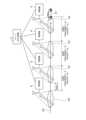
図2は、GNSS受信データの通信例を説明する図である。図2には、図1に示した路側機4と、サーバ5と、車両A1と、が示してある。路側機4は、例えば、路側においてスポット的に配置される。図2では、車両A1に搭載されているGNSS受信機2および車載器3の図示を省略している。図2において、車両A1は、矢印A3に示すように、図2の左側から右側に向かって走行する。 FIG. 2 is a diagram illustrating an example of communication of GNSS received data. In FIG. 2, the
車両A1に搭載されたGNSS受信機2は、GNSSの衛星から送られてくる測位信号を受信して復調し、GNSS受信データを周期的に車載器3に出力する。例えば、GNSS受信機2は、GNSS受信データを数Hzの周期で車載器3に出力する。 The GNSS
車載器3は、路側機4の通信エリアA2外においては、GNSS受信機2から出力されるGNSS受信データを、路側機4に送信できない。そこで、車載器3は、路側機4の通信エリアA2外においては、GNSS受信機2から出力されるGNSS受信データを、記憶部に記憶する。そして、車載器3は、路側機4の通信エリアA2内に入ると、記憶部に記憶したGNSS受信データを、路側機4に送信する。また、車載器3は、路側機4の通信エリアA2内においても、GNSS受信機2から周期的に出力されるGNSS受信データを、路側機4に送信する。 The
例えば、GNSS受信機2は、図2に示す区間1において、GNSS受信データを数Hzの周期で車載器3に出力する。車載器3は、図2の区間1aに示す路側機4の通信エリアA2外においては、GNSS受信データを路側機4に送信できないので記憶部に記憶する。車載器3は、図2の区間1に形成されている通信エリアA2内に入ると、記憶部に記憶した区間1aのGNSS受信データを、路側機4に送信する。また、車載器3は、区間1に形成された通信エリアA2内においても、GNSS受信機2から周期的に出力されるGNSS受信データを、路側機4に送信する。すなわち、車載器3は、区間1aを含む区間1におけるGNSS受信データを、区間1に通信エリアA2を形成している路側機4に送信する。 For example, in
車載器3は、図2に示す区間2,3においても、区間1と同様に、GNSS受信データを、路側機4に送信する。これにより、サーバ5は、路側機4の通信エリアA2内外における、車両A1が走行した走行経路を算出できる。 The
図3は、GNSS受信機2のブロック構成例を示した図である。図3に示すように、GNSS受信機2は、プロセッサ11と、記憶部12と、通信部13と、受信部14と、バス15と、を有している。 FIG. 3 is a diagram showing an example of the block configuration of the
プロセッサ11は、バス15を介してGNSS受信機2の他の要素を制御する。プロセッサ11として、例えば、汎用CPU(Central Processing Unit)が用いられる。また、プロセッサ11は、所定のプログラムを実行することにより、GNSS受信データを生成する。
記憶部12は、他の要素から様々な情報を取得し、一時的あるいは恒久的にその情報を保持する。記憶部12は、いわゆる一次記憶装置と二次記憶装置の総称である。記憶部12は、物理的に複数配置されてもよい。記憶部12として、例えば、DRAM(Direct Random Access Memory)、HDD(Hard Disk Drive)、SSD(Solid State Drive)が用いられる。 The
通信部13は、通信路を介して外部の機器と通信を行う。通信部13が通信する対象(通信対象)の機器には、車載器3が含まれる。 The
受信部14は、衛星からの測位信号を受信し、バス15を介して測位信号をプロセッサ11に出力する。 The receiving
図4は、車載器3のブロック構成例を示した図である。図4に示すように、車載器3は、プロセッサ21と、記憶部22と、通信部23と、DSRC通信部24と、バス25と、を有している。 FIG. 4 is a diagram showing an example of the block configuration of the on-
プロセッサ21は、バス25を介して車載器3の他の要素を制御する。プロセッサ21として、例えば、汎用CPUが用いられる。 The
記憶部22は、他の要素から様々な情報を取得し、一時的あるいは恒久的にその情報を保持する。記憶部22に記憶される情報には、GNSS受信機2から出力されたGNSS受信データが含まれる。記憶部22は、いわゆる一次記憶装置と二次記憶装置の総称である。記憶部22は、物理的に複数配置されてもよい。記憶部22として、例えば、DRAM、HDD、SSDが用いられる。 The
通信部23は、通信路を介して外部の機器と通信を行う。通信部23が通信する対象(通信対象)の機器には、GNSS受信機2が含まれる。 The
DSRC通信部24は、路側機4と、DSRCに基づいた双方向通信を行う。例えば、DSRC通信部24は、通信部23がGNSS受信機2から受信したGNSS受信データを、DSRCに基づいて路側機4に送信する。また、DSRC通信部24は、記憶部22に記憶されたGNSS受信データを、DSRCに基づいて路側機4に送信する。 The
図5は、路側機4のブロック構成例を示した図である。図5に示すように、路側機4は、プロセッサ31と、記憶部32と、通信部33と、DSRC通信部34と、バス35と、を有している。 FIG. 5 is a diagram showing an example of the block configuration of the
プロセッサ31は、バス35を介して路側機4の他の要素を制御する。プロセッサ31として、例えば、汎用CPUが用いられる。 The
記憶部32は、他の要素から様々な情報を取得し、一時的あるいは恒久的にその情報を保持する。記憶部32は、いわゆる一次記憶装置と二次記憶装置の総称である。記憶部32は、物理的に複数配置されてもよい。記憶部32として、例えば、DRAM、HDD、SSDが用いられる。 The
通信部33は、通信路を介して外部の機器と通信を行う。通信部33が通信する対象(通信対象)の機器には、サーバ5が含まれる。 The
DSRC通信部34は、車載器3と、DSRCに基づいた双方向通信を行う。例えば、DSRC通信部34は、車載器3から送信されたGNSS受信データを、DSRCに基づいて受信する。 The
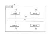
図6は、サーバ5のブロック構成例を示した図である。図6に示すように、サーバ5は、プロセッサ41と、記憶部42と、通信部43と、バス44と、を有している。 FIG. 6 is a diagram showing an example of the block configuration of the
プロセッサ41は、バス44を介してサーバ5の他の要素を制御する。プロセッサ41として、例えば、汎用CPUが用いられる。
記憶部42は、他の要素から様々な情報を取得し、一時的あるいは恒久的にその情報を保持する。記憶部42は、いわゆる一次記憶装置と二次記憶装置の総称である。記憶部42は、物理的に複数配置されてもよい。記憶部42として、例えば、DRAM、HDD、SSDが用いられる。 The
通信部43は、通信路を介して外部の機器と通信を行う。通信部43が通信する対象(通信対象)の機器には、路側機4が含まれる。 The
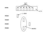
図7は、DSRC通信の概要を説明する図である。DSRCの無線アクセス方式は、TDMA(Time Division Multiple Access)方式である。路側機が、通信タイミングの基準となる。路側機は、最大8台の車載器と通信する。 FIG. 7 is a diagram illustrating an overview of DSRC communication. The radio access method of DSRC is a TDMA (Time Division Multiple Access) method. The roadside device serves as the standard for communication timing. The roadside device communicates with up to eight onboard devices.
DSRCのフレームは、FCMS(Flame Control Message Slot)と、MDS(Message Data Slot)と、ACTS(Activation Slot)と、を有する。DSRCのフレームは、MDS数とACTS数とが、次の式(1)および式(2)を満たすように構成される。 A DSRC frame has an FCMS (Flame Control Message Slot), an MDS (Message Data Slot), and an ACTS (Activation Slot). A DSRC frame is configured such that the number of MDS and the number of ACTS satisfy the following equations (1) and (2).
MDS数+ACTS数<=8 …(1)
ACTS数<=3 …(2)Number of MDS + number of ACTS <= 8 ... (1)
Number of ACTS <= 3...(2)
FCMSには、路側機によって、MDSの割り当て等のフレーム構造が記述される。MDSは、車載器と路側機とがダウンリンクおよびアップリンクのデータ通信をするためのスロットである。車載器は、FCMSを参照し、MDSの割り当てを把握する。 In the FCMS, a frame structure such as MDS assignment is described by the roadside device. The MDS is a slot for downlink and uplink data communication between the onboard device and the roadside device. The onboard device refers to the FCMS and understands the MDS assignment.
例えば、図7に示す車載器Aは、FCMSを参照し、MDS(1)のダウンリンクの割り当てを把握する。車載器Aは、MDS(1)において、路側機のダウンリンクデータを受信する。 For example, the onboard device A shown in FIG. 7 refers to the FCMS and grasps the downlink assignment of MDS (1). The onboard device A receives downlink data from the roadside device in MDS (1).
また、例えば、図7に示す車載器Bは、FCMSを参照し、MDS(2)のアップリンクの割り当てを把握する。車載器Bは、MDS(2)において、路側機にアップリンクデータを送信する。 Further, for example, the on-vehicle device B shown in FIG. 7 refers to the FCMS and grasps the uplink assignment of MDS (2). The onboard device B transmits uplink data to the roadside device in MDS (2).
また、図7に示す車載器A,B,Cは、FCMSを参照し、MDS(4)のダウンリンク(同報)を把握する。車載器A,B,Cは、MDS(4)において、路側機のダウンリンクデータ(同報データ)を受信する。 Furthermore, the onboard devices A, B, and C shown in FIG. 7 refer to the FCMS and grasp the downlink (broadcast) of the MDS (4). The onboard devices A, B, and C receive downlink data (broadcast data) from the roadside device in the MDS (4).
ACTSは、車載器が路側機に対し、リンク要求を行うためのスロットである。路側機は、車載器からのリンク要求に応じて、車載器にMDSを割り当てる。 ACTS is a slot for the onboard device to issue a link request to the roadside device. The roadside device allocates an MDS to the onboard device in response to a link request from the onboard device.
図8は、ACTSを説明する図である。図8に示すように、ACTSには、6つのACTC(Activation Channel)が含まれる。車載器は、ランダムに1つのACTCを選択し、リンク要求を行う。例えば、図8に示す車載器Aは、先頭のACTCを選択し、リンク要求を行っている。 FIG. 8 is a diagram explaining ACTS. As shown in FIG. 8, ACTS includes six ACTCs (Activation Channels). The onboard device randomly selects one ACTC and makes a link request. For example, the onboard device A shown in FIG. 8 selects the first ACTC and requests a link.
リンク要求が行われたフレーム以降のフレームに含まれるFCMSにおいて、通信が許可された車載器の車載器IDと、MDSとが示される。リンク要求を行った車載器は、FCMSに含まれる車載器IDと、MDSとに基づいて、路側機と通信を行う。 In the FCMS included in frames subsequent to the frame in which the link request was made, the onboard device ID of the onboard device with which communication is permitted and the MDS are indicated. The onboard device that has made the link request communicates with the roadside device based on the onboard device ID included in the FCMS and the MDS.
リンク要求は、衝突する場合がある。例えば、図8に示す車載器B,Dは、先頭から3つ目のACTCを選択し、リンク要求を行っている。この場合、車載器B,Dのリンク要求は、衝突する。同じACTCを選択してリンク要求を行った車載器B,Dは、車載器B,Dの車載器IDがFCMSに含まれていない場合、路側機においてリンク要求が受け付けられなかったと判定し、再度リンク要求を行う。 Link requests may conflict. For example, the onboard devices B and D shown in FIG. 8 select the third ACTC from the top and issue a link request. In this case, the link requests of the onboard devices B and D collide. If the onboard devices B and D that selected the same ACTC and made a link request do not include the onboard device IDs of the onboard devices B and D in the FCMS, the roadside device determines that the link request was not accepted and requests the link request again. Make a link request.
上記したように、路側機は、最大8台の車載器と通信できる。従って、路側機は、8台の路側機とリンクを確立している場合、新たな車載器のリンク要求を受付けない。 As described above, the roadside device can communicate with up to eight onboard devices. Therefore, when the roadside device has established links with eight roadside devices, it does not accept a link request from a new onboard device.
リンク要求が受け付けられなかった車載器の車載器IDは、FCMSに含まれない。リンク要求を行ったにも関わらず、FCMSに車載器IDが含まれなかった車載器は、再度リンク要求を行う。 The onboard device ID of the onboard device for which the link request is not accepted is not included in the FCMS. An on-vehicle device whose on-vehicle device ID is not included in the FCMS despite having made a link request makes a link request again.
なお、上記の式(2)に示したように、DSRCのフレームは、最大3つのACTSを含むことができる。従って、路側機は、1フレームに最大18個のACTCを設定できる。 Note that, as shown in equation (2) above, a DSRC frame can include a maximum of three ACTS. Therefore, the roadside device can set up to 18 ACTCs in one frame.
図9は、DSRC通信の通信例を説明する図である。従来のDSRC通信の利用方法では、例えば、図9に示すように、渋滞等によって通信エリアX1内に多数の車載器が存在する場合であっても、通信の輻輳が生じる可能性は低い。 FIG. 9 is a diagram illustrating an example of DSRC communication. In the conventional method of using DSRC communication, for example, as shown in FIG. 9, even if a large number of on-vehicle devices exist within the communication area X1 due to traffic jams, there is a low possibility that communication congestion will occur.
例えば、DSRC通信は、料金情報の収集または料金所情報の通知に利用される。これらの情報のサイズは小さいため、DSRC通信は、短いトランザクションで通信が完了し、通信の輻輳が生じる可能性は低い。 For example, DSRC communication is used to collect toll information or notify toll gate information. Since the size of this information is small, DSRC communication is completed in a short transaction, and communication congestion is unlikely to occur.
また、通信エリアX1において通信が完了した車載器は、通常、通信エリアX1内において、リンク要求を出さなくなる。例えば、車載器は、通常、通信エリアX1において、1回通信を終了すると、その後、通信を行わなくなる。これは、料金情報や料金所情報が他の通信エリアに移動するまでに更新される可能性は低いためである。つまり、車載器は、通信エリアX1にエリアインしたときにおいて路側機と1回通信し、その後通信しなくなるため、通信の輻輳が生じる可能性は低い。 Further, the on-vehicle device that has completed communication in the communication area X1 usually does not issue a link request within the communication area X1. For example, once the on-vehicle device normally completes communication once in the communication area X1, it no longer communicates. This is because it is unlikely that the toll information and toll gate information will be updated before moving to another communication area. In other words, the on-vehicle device communicates with the roadside device once when it enters the communication area X1, and then stops communicating, so communication congestion is unlikely to occur.
しかし、図1および図2で説明したように、サーバ5において、車両A1の走行経路を走行車線等まで含めて詳細に算出する場合、サーバ5は、車両A1の走行経路を詳細に把握しなくてはならない。この走行経路の算出に必要な情報として、車載器3は、通信エリアA2内外で取得したGNSS受信データを路側機4に送信する。GNSS受信データは、車両A1の細かな位置に対応する情報であるため、情報のサイズは大きい。このため、図1および図2で説明した測位システム1では、通信の輻輳が生じる可能性が高くなる。そこで、測位システム1では、車載器と路側機との通信の輻輳を抑制するため、下記の処理を行う。 However, as explained in FIGS. 1 and 2, when the
また、車載器3は、通信エリアA2内外のGNSS受信データを路側機4に送信する。すなわち、車載器3は、通信エリアA2の外で取得し、蓄積してきたGNSS受信データを通信エリアA2の中にいる間に送信する。また、GNSS受信データは通信エリアA2にいる間も随時取得されるため、これらのGNSS受信データを送信することも考えられる。このため、測位システム1では、車載器3から路側機4に送信されるGNSS受信データは大容量となり、また、同じ車載器3が複数回の通信を行うこともあり得る。そのため、スロットの割り当て方によっては、一部の車載器において未送信データが増える場合がある。そこで、測位システム1では、一部の車載器において未送信データが増えないよう下記の処理を行う。 Further, the
図10は、測位システム1の動作例を説明する図である。図10には、3台の車載器3(車載器3a~3c)と、1台の路側機4と、が示してある。 FIG. 10 is a diagram illustrating an example of the operation of the
・車載器は、GNSS受信データを路側機4に送信する際、未送信データ容量(未送信データ容量の情報)を路側機に通知する。未送信データ容量とは、車載器がGNSS受信データを路側機4に送信した後の、残りのGNSS受信データ量である。なお、未送信データ容量は、車載器が通信エリアA2に入った直後の時点では、前の路側機4の通信エリアで送信が完了しなかったデータと、その後通信エリアA2に入るまでに蓄積されたGNSSデータの容量の合計に対応する。 - When transmitting GNSS received data to the
例えば、図10の矢印A11a,A11bに示すように、車載器3a,3bは、GNSS受信データと、未送信データ容量とを路側機4に送信する。 For example, as shown by arrows A11a and A11b in FIG. 10, the
なお、以下で説明するが、車載器3a,3bの各々は、路側機4から、同報通信によって、リンク要求を行うか否かを判断するための閾値(パラメータ)を受信する。車載器3a,3bの各々は、路側機4から同報通信された閾値と、未送信データ容量との比較結果に基づいて、リンク要求を路側機4に送信する。路側機4は、車載器3a,3bのリンク要求に応じて、アップリンクのMDSを車載器3a,3bに割り当てる。MDSが割り当てられた車載器3a,3bは、矢印A11a,A11bに示すGNSS受信データと、未送信データ容量とを路側機4に送信する。 Note that, as will be explained below, each of the on-
・路側機は、未送信データ容量が大きい車載器を優先してMDSを割り当てる。 - The roadside device assigns MDS giving priority to the onboard device with a large amount of unsent data.
例えば、図10の車載器3aの未送信データ容量dc1は、車載器3bの未送信データ容量dc2より大きいとする。この場合、路側機4は、次のフレーム以降における車載器3a,3bのアップリンクのMDS割り当てにおいて、車載器3aに割り当てるMDS数を、車載器3bに割り当てるMDS数より大きくする。すなわち、路側機4は、車載器3a,3の各々における未送信データ容量の差が小さくなるように、車載器3a,3bの各々に対し、MDSを割り当てる。これにより、一部の車載器において、未送信データが増える(集中する)のを抑制できる。 For example, it is assumed that the untransmitted data capacity dc1 of the on-
・路側機は、未送信データ容量を把握(送信)していない車載器からリンク要求を受信した場合、次のフレームにおいて、少なくとも1つのMDSを割り当て、未送信データ容量を取得する。 - When the roadside device receives a link request from an onboard device that does not know (transmit) the untransmitted data capacity, it allocates at least one MDS in the next frame and acquires the untransmitted data capacity.
例えば、図10の車載器3cは、路側機4の通信エリアにエリアインしたとする。この場合、路側機4は、車載器3cの未送信データ容量を把握していない。路側機4は、未送信データ容量を把握していない車載器3cのリンク要求を受信すると、次のフレームにおいて、少なくとも1つのアップリンクのMDSを車載器3cに割り当てる。車載器3cは、割り当てられたMDSにおいて、GNSS受信データと、未送信データ容量とを路側機4に送信し、路側機4は、車載器3cから未送信データ容量を取得する。 For example, assume that the on-
なお、路側機は、車載器が路側機の通信エリアをエリアアウトすると、車載器から受信した未送信データ容量を破棄する。言い換えれば、路側機は、車載器が路側機の通信エリアをエリアアウトすると、エリアアウトした車載器の未送信データ容量を把握していない状態となる。 Note that when the onboard device moves out of the communication area of the roadside device, the roadside device discards the untransmitted data capacity received from the onboard device. In other words, when the onboard device goes out of the communication area of the roadside device, the roadside device is in a state where it does not know the untransmitted data capacity of the onboard device that went out of the area.
・路側機は、車載器から受信した未送信データ容量に基づいて閾値を算出し、算出した閾値を同報通信で車載器に通知する。閾値は、車載器が未送信データ容量に基づいて、路側機に対しリンク要求を行うか否かを判断するための判断基準である。 - The roadside device calculates a threshold based on the amount of untransmitted data received from the onboard device, and notifies the onboard device of the calculated threshold via broadcast communication. The threshold value is a criterion for determining whether or not the on-vehicle device issues a link request to the roadside device based on the untransmitted data capacity.
例えば、図10の矢印A13に示すように、路側機4は、同報通信によって、閾値を車載器3a~3cに送信する。 For example, as shown by arrow A13 in FIG. 10, the
なお、閾値は、各車載器の未送信データ容量の合計値に基づいて決定されてもよい。例えば、路側機は、合計値が大きい程、閾値を大きくしてもよい。合計値が多い状況では未送信データ容量の大きい車載器が存在する可能性が高いため、閾値の設定をこのようにすることで、リンク要求を行う車載器をより未送信データ容量が大きい車載器に限定することができる。 Note that the threshold value may be determined based on the total value of the untransmitted data capacity of each on-vehicle device. For example, the roadside device may increase the threshold value as the total value increases. In situations where the total value is large, there is a high possibility that there is an on-board device with a large amount of unsent data, so by setting the threshold in this way, the on-board device that makes a link request is more likely to have an on-board device with a large amount of unsent data. can be limited to.
また、閾値は、路側機の通信エリア内に存在する車載器の数に基づいて決定されてもよい。例えば、路側機は、車載器の数が大きい程、閾値を大きくしてもよい。通信エリア内に存在する車載器の数が大きい状況で小さい閾値を用いると、より多くの車載器がリンク要求を行うおそれが増し、未送信データ容量の大きい車載機のリンク要求が拒否されやすくなってしまうためである。 Further, the threshold value may be determined based on the number of on-vehicle devices existing within the communication area of the roadside device. For example, the roadside device may increase the threshold value as the number of onboard devices increases. If a small threshold is used in a situation where a large number of on-vehicle devices exist within the communication area, there is an increased possibility that more on-vehicle devices will make link requests, and link requests from on-vehicle devices with a large amount of untransmitted data will be more likely to be rejected. This is because the
また、閾値は、各車載器の未送信データ容量の合計値と、路側機の通信エリア内に存在する車載器の数とに基づいて決定されてもよい。 Further, the threshold value may be determined based on the total value of the untransmitted data capacity of each on-vehicle device and the number of on-vehicle devices existing within the communication area of the roadside device.
また、閾値は、固定値であってもよい。閾値を固定値にする場合には、予め各車載器に閾値を記録しておき同報通信を省略しても良い。これにより同報通信に用いるスロットを他の用途に割り当てることが可能となる。 Further, the threshold value may be a fixed value. When the threshold value is set to a fixed value, the threshold value may be recorded in each vehicle-mounted device in advance and broadcast communication may be omitted. This makes it possible to allocate slots used for broadcast communication to other uses.
・車載器は、同報通信で受信した閾値と、未送信データ容量とを比較し、未送信データ容量が閾値より大きければ、路側機に対しリンク要求を行う。車載器は、未送信データ容量が閾値以下であれば、路側機に対しリンク要求を行わない。 - The onboard device compares the threshold value received through broadcast communication with the unsent data capacity, and if the unsent data capacity is larger than the threshold value, requests a link to the roadside device. If the untransmitted data capacity is less than or equal to the threshold, the onboard device does not issue a link request to the roadside device.
例えば、図10の車載器3cは、路側機4の通信エリアにエリアインし、同報通信により、閾値を受信する。車載器3cは、未送信データ容量が閾値より大きければ、図10の矢印A12に示すように、路側機4に対しリンク要求を行う。一方、車載器3cは、未送信データ容量が閾値以下であれば、路側機4に対しリンク要求を行わない。これにより、未送信データ容量の小さい車載器のリンク要求は制限され、未送信データ容量の大きい車載器のリンク要求が優先される。従って、路側機と車載器との通信の輻輳が抑制される。 For example, the
図11は、測位システム1の動作例を説明する図である。図11には、第nフレームと、第n+1フレームとが示してある。図11に示す路側機は、図10に示した路側機4に対応する。図11に示す車載器A~Cは、図10に示した車載器3a~3cに対応する。 FIG. 11 is a diagram illustrating an example of the operation of the
車載器A~Cは、MDS(1)において、路側機から閾値を受信する。MDS(1)は、同報通信のスロットである。車載器A~Cは、路側機とリンクを確立していなくても、FCMSを参照し、同報通信のMDS(1)において、路側機から閾値を受信できる。 The onboard devices A to C receive the threshold value from the roadside device in MDS (1). MDS(1) is a slot for broadcast communication. Even if the onboard devices A to C do not establish a link with the roadside device, they can refer to the FCMS and receive the threshold value from the roadside device in the MDS (1) of broadcast communication.
車載器A,Bは、FCMSを参照し、GNSS受信データを路側機に送信する。このとき、車載器A,Bは、未送信データ容量を路側機に送信する。 The onboard devices A and B refer to the FCMS and transmit the GNSS reception data to the roadside device. At this time, the onboard devices A and B transmit the untransmitted data capacity to the roadside device.
なお、車載器A,Bは、第nフレームより前のフレームにおいて受信した閾値と、未送信データ容量とを比較してリンク要求を路側機に送信している。路側機は、第nフレームより前のフレームにおける車載器A,Bからのリンク要求に応じて、図11に示すように、第nフレームおよび第n+1フレームにおいて、アップリンクのMDSを車載器A,Bに割り当てている。路側機は、MDSを車載器A,Bに割り当てる際、車載器A,Bから送信される未送信データ容量に基づいて、MDSの車載器A,Bへの割り当てを決定する。例えば、車載器Aの未送信データ容量が、車載器Bの未送信データ容量より大きい場合、路側機は、車載器Aに対するMDSの割り当て数を、車載器BのMDSの割り当て数より多くする。 Note that the vehicle-mounted devices A and B compare the untransmitted data capacity with the threshold value received in frames before the n-th frame, and transmit the link request to the roadside device. In response to link requests from onboard devices A and B in frames before the nth frame, the roadside device transmits the uplink MDS to onboard devices A and B in the nth frame and the n+1th frame, as shown in FIG. It is assigned to B. When allocating the MDS to the onboard devices A and B, the roadside device determines the allocation of the MDS to the onboard devices A and B based on the untransmitted data capacity transmitted from the onboard devices A and B. For example, if the untransmitted data capacity of onboard device A is larger than the untransmitted data capacity of onboard device B, the roadside device assigns a larger number of MDSs to onboard device A than the number of MDSs assigned to onboard device B.
車載器Cは、第nフレームのMDS(1)において受信した閾値と、未送信データ容量とを比較し、未送信データ容量が閾値より大きい場合、第nフレームのACTSにおいて、リンク要求を路側機に送信する。路側機は、車載器Cからのリンク要求を受信すると、次の第n+1フレームにおいて、少なくとも1つのアップリンクのMDSを車載器Cに割り当てる。例えば、路側機は、第n+1フレームのMDS(7)を車載器Cに割り当てる。これにより、路側機は、車載器Cの未送信データ容量を把握できる。 The onboard device C compares the untransmitted data capacity with the threshold value received in the MDS (1) of the nth frame, and if the untransmitted data capacity is larger than the threshold value, the onboard device C transmits the link request to the roadside device in the ACTS of the nth frame. Send to. Upon receiving the link request from the onboard device C, the roadside device allocates at least one uplink MDS to the onboard device C in the next (n+1)th frame. For example, the roadside device assigns the MDS (7) of the n+1 frame to the onboard device C. Thereby, the roadside device can grasp the untransmitted data capacity of the onboard device C.
図12は、測位システムの動作例を示したシーケンス図である。図12に示す路側機は、図10に示した路側機4に対応する。図12に示す車載器A~Cは、図10に示した車載器3a~3cに対応する。 FIG. 12 is a sequence diagram showing an example of the operation of the positioning system. The roadside machine shown in FIG. 12 corresponds to the
路側機は、フレームのFCMSにおいて、通信エリア内の車載器A,B,Cに対し、MDSの割り当てを通知する(S1)。以下では、路側機は、車載器A,Bに、MDSを割り当てたとする。路側機Cは、路側機の通信エリアにエリアインしたとする。 The roadside device notifies the onboard devices A, B, and C within the communication area of the MDS assignment in the FCMS of the frame (S1). In the following, it is assumed that the roadside device allocates the MDS to the onboard devices A and B. It is assumed that the roadside device C enters the communication area of the roadside device.
路側機は、フレームのMDS(1)において、通信エリア内の車載器A,B,Cに対し、同報通信によって閾値を通知する(S2)。 The roadside device notifies the onboard devices A, B, and C within the communication area of the threshold value by broadcast communication in the MDS (1) of the frame (S2).
車載器Aは、S1のFCMSにおけるMDSの割り当て情報に従って、GNSS受信データと、未送信データ容量とを路側機に送信する(S3)。 The vehicle-mounted device A transmits the GNSS received data and the untransmitted data capacity to the roadside device according to the MDS allocation information in the FCMS of S1 (S3).
車載器Bは、S1のFCMSにおけるMDSの割り当て情報に従って、GNSS受信データと、未送信データ容量とを路側機に送信する(S4)。 The vehicle-mounted device B transmits the GNSS received data and the untransmitted data capacity to the roadside device according to the MDS allocation information in the FCMS of S1 (S4).
路側機の通信エリアにエリアインした車載器Cは、S2にて同報送信された閾値と、未送信データ容量とを比較し、未送信データ容量が閾値より大きいか否かを判定する(S5)。 The onboard device C that has entered the communication area of the roadside device compares the threshold value broadcasted in S2 with the untransmitted data capacity, and determines whether the untransmitted data capacity is larger than the threshold value (S5 ).
車載器Cは、未送信データ容量が閾値より大きいと判定した場合(S5のYes)、フレームのACTSにおいて、路側機に対し、リンク要求を送信する(S6)。一方、車載器Cは、未送信データ容量が閾値より大きくないと判定した場合(S5のNo)、路側機に対し、リンク要求を送信しない。 When the vehicle-mounted device C determines that the untransmitted data capacity is larger than the threshold (Yes in S5), it transmits a link request to the roadside device in the ACTS of the frame (S6). On the other hand, when the vehicle-mounted device C determines that the untransmitted data capacity is not larger than the threshold (No in S5), it does not transmit the link request to the roadside device.
路側機は、S6のリンク要求を受信すると、車載器Cの未送信データ容量を把握しているか否かを判定する(S7)。 When the roadside device receives the link request in S6, it determines whether it knows the untransmitted data capacity of the onboard device C (S7).
路側機は、車載器Cの未送信データ容量を把握していると判定した場合(S7のYes)、各車載器A,B,Cの未送信データ容量に応じたスロット数となるように、MDSの割り当てを決定する(S8)。 If the roadside device determines that it knows the untransmitted data capacity of the onboard device C (Yes in S7), the roadside device determines that the number of slots corresponds to the untransmitted data capacity of each of the onboard devices A, B, and C. MDS allocation is determined (S8).
一方、路側機は、車載器Cの未送信データ容量を把握していないと判定した場合(S7のNo)、車載器Cに対し、1つのMDSの割り当てを決定する(S9)。また、路側機は、車載器A,Bに対し、車載器A,Bの未送信データ容量に応じたスロット数となるように、MDSの割り当てを決定する(S9)。 On the other hand, if the roadside device determines that it does not know the untransmitted data capacity of the onboard device C (No in S7), it determines the allocation of one MDS to the onboard device C (S9). Further, the roadside device determines MDS allocation to the onboard devices A and B so that the number of slots corresponds to the untransmitted data capacity of the onboard devices A and B (S9).
路側機は、S7にてYesの判定を行った場合、車載器A,B,Cの未送信データ容量に基づいて、閾値を決定し、S7にてNoの判定を行った場合、車載器A,Bの未送信データ容量に基づいて、閾値を決定する(S10)。 If the roadside device makes a Yes determination in S7, the roadside device determines a threshold value based on the untransmitted data capacity of the onboard devices A, B, and C; if it makes a No determination in S7, the roadside device determines the threshold value based on the untransmitted data capacity of the onboard devices , B, a threshold value is determined based on the untransmitted data capacity of , B (S10).
路側機は、フレームのFCMSにおいて、通信エリア内の車載器A,B,Cに対し、S8またはS9で決定したMDSの割り当てを通知する(S11)。 The roadside device notifies the onboard devices A, B, and C within the communication area of the MDS assignment determined in S8 or S9 in the FCMS of the frame (S11).
路側機は、フレームのMDS(1)において、通信エリア内の車載器A,B,Cに対し、同報通信によって、S10で決定した閾値を通知する(S12)。 In the MDS (1) of the frame, the roadside device notifies the onboard devices A, B, and C within the communication area of the threshold determined in S10 by broadcast communication (S12).
図13は、測位システム1の効果の一例を説明する図である。図13には、3台の路側機(図示せず)が形成する通信エリアA21~A23が示してある。 FIG. 13 is a diagram illustrating an example of the effects of the
上記したように、路側機は、未送信データ量の多い車載器に対し、未送信データ量の少ない車載器より多くのMDSを割り当てる。例えば、通信エリアA21を形成する路側機は、通信エリアA21において、各車載器の未送信データ容量が均等になるように、車載器にMDSを割り当てる。 As described above, the roadside device allocates more MDS to an on-vehicle device with a large amount of untransmitted data than an on-vehicle device with a small amount of untransmitted data. For example, the roadside devices forming the communication area A21 allocate MDSs to the onboard devices so that the untransmitted data capacity of each onboard device is equalized in the communication area A21.
これにより、通信エリアA21の先において分岐した道路に形成された通信エリアA22,A23では、車載器の未送信データ容量の偏りが抑制される。通信エリアA22,A23を通過する車載器は、通信エリアA21で送信できなかったGNSS受信データを、通信エリアA22,A23で送信できる。また、通信エリアA22,A23を形成する路側機は、GNSS受信データの受信漏れを抑制できる。 As a result, in the communication areas A22 and A23 formed on roads branching off beyond the communication area A21, the unbalanced untransmitted data capacity of the onboard equipment is suppressed. The onboard equipment passing through the communication areas A22 and A23 can transmit the GNSS reception data, which could not be transmitted in the communication area A21, in the communication areas A22 and A23. Moreover, the roadside devices forming the communication areas A22 and A23 can suppress the omission of reception of GNSS reception data.
以上説明したように、路側機4は、複数の車載器3の各々から送信されるGNSS受信データと、未送信のGNSS受信データの容量を示す未送信データ容量とを受信するDSRC通信部34と、未送信データ容量に基づいて、複数の車載器3の各々に対し、GNSS受信データを送信するためのスロットを割り当てるプロセッサ31と、を有する。これにより、路側機4は、スロットを適切に車載器3に割り当てることができる。 As explained above, the
また、車載器3は、フレーム構造を記述したFCMSを参照し、GNSS受信データと、未送信のGNSS受信データの容量を示す未送信データ容量とを送信するスロットを判定するプロセッサ21と、プロセッサ21が判定したスロットにおいて、GNSS受信データと、未送信データ容量とを路側機4に送信するDSRC通信部24と、を有する。これにより、路側機4は、スロットを適切に車載器3に割り当てることができる。 The
(変形例1)
上記第1の実施の形態では、車載器3は、GNSS受信データとともに未送信データ容量を路側機4に送信するとしたがこれに限られない。例えば、車載器3は、路側機4とのリンク確立後、最初のGNSS受信データの送信の際に、未送信データ容量を路側機4に送信し、その後、未送信データ容量を路側機4に送信しなくてもよい。(Modification 1)
In the first embodiment, the vehicle-mounted
路側機4は、車載器3から最初に送信された未送信データ容量と、車載器3から送信されるGNSS受信データとに基づいて、未送信データ容量の受信後における車載器3の未送信データ容量を算出してもよい。例えば、路側機4は、最初に送信された未送信データ容量から、その後、車載器3から送信されるGNSS受信データのデータ量を減算し、車載器3の未送信データ容量を算出してもよい。 Based on the untransmitted data capacity initially transmitted from the
車載器3は、GNSS受信機2からGNSS受信データが出力され、未送信データ容量に変化が生じたときに、未送信データ容量を路側機4に送信してもよい。 The vehicle-mounted
(変形例2)
上記第1の実施の形態では、車載器3は、GNSS受信データを路側機4に送信するとしたがこれに限られない。例えば、GNSS受信機2が測位データを出力する場合、車載器3は、測位データを路側機4に送信してもよい。また、GNSS受信機2が、車載器3の位置の計算まで行うことができるのであれば、位置のデータを路側機4に送信しても良い。すなわち、GNSSによる測位に関するどの段階のデータを送信するかは、測位システム1の設計に応じて任意のものを採用することができる。(Modification 2)
In the first embodiment, the vehicle-mounted
また、車載器3が路側機4に送信するデータは、GNSSに関連するデータに限らない。車載器3によって収集され、路側機4に送信することが有益であるデータであれば、他のデータであっても構わない。例えば、車載器3が、タイヤの回転数等から計算した移動距離や移動速度等のデータを路側機4に送信する場合に、上記第1の実施の形態の構成を適用してもよい。 Furthermore, the data that the
(変形例3)
上記第1の実施の形態では、車載器3は未送信データ容量が予め同報送信された閾値より大きいことを条件にリンク要求を送信していた。しかし、車載器3にて自身の未送信データ容量が閾値より大きいか否かを判定しない構成としてもよい。この場合、車載器3は必要に応じてリンク要求を送信し、路側機4は自身の判断で当該リンク要求を受け入れてスロットを割り当てるか否かを決定する。このようにすることで、車載器3側で判断すべき事項を減らすことができるので、車載器3の構成をより簡易にすることができる。また、閾値を同報送信する必要がなくなるので、同報送信用のスロットを他の用途に割り当てることができる。(Modification 3)
In the first embodiment described above, the on-
(第2の実施の形態)
第2の実施の形態では、車載器は、路側機に送信するデータを間引き、通信帯域の逼迫を抑制する。また、路側機は、車載器に送信するデータを間引き、通信帯域の逼迫を抑制する。(Second embodiment)
In the second embodiment, the on-vehicle device thins out data to be transmitted to the roadside device to suppress communication band strain. In addition, the roadside device thins out the data sent to the onboard device to suppress the strain on the communication band.
図14は、第2の実施の形態に係る測位システム51の構成例を示した図である。図14に示すように、測位システム51は、車載器52と、路側機53と、を有している。車載器52のブロック構成は、図4で説明した車載器3のブロック構成と同様であり、その説明を省略する。路側機53のブロック構成は、図5で説明した路側機4のブロック構成と同様であり、その説明を省略する。 FIG. 14 is a diagram showing a configuration example of a
車載器52および路側機53は、DSRCに基づいた双方向通信を行う。路側機53は、例えば、数km~20kmの間隔で路側に配置される。車載器52は、路側機53が形成する通信エリアA31内において、路側機53と通信する。 The
車載器52は、衛星受信情報を路側機53に送信する。衛星受信情報は、GNSSの衛星からの測位信号を受信したGNSS受信機(図示せず)から出力される情報である。衛星受信情報は、例えば、測位信号、GNSS受信データ、または測位データから得られる各種情報である。 The
車載器52は、通信エリアA31内において、衛星受信情報を路側機53に送信する。車載器52は、通信エリアA31外においては、衛星受信情報を記憶部に記憶する。車載器52は、通信エリアA31にエリアインすると、記憶部に記憶した衛星受信情報を路側機53に送信する。 The
渋滞時には、多数の車載器52と、路側機53とが通信エリアA31内において通信を行う。本実施の形態では、車両の走行経路を算出するために定期的に計測した車両の位置を用いる。そのため、GNSS受信機から出力される衛星受信情報の単位時間当たりの情報量は、車両の速度に関わらず一定である。そのため、渋滞時には、車載器52と路側機53との通信の帯域が逼迫する。 During traffic congestion, a large number of on-
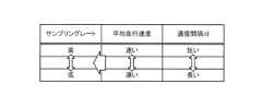
そこで、車載器52は、衛星受信情報を記憶部に記憶(蓄積)した時間の長さに基づいて、路側機53に送信する衛星受信情報を、時系列上において間引き、路側機53に送信する。言い換えれば、車載器52は、前の路側機53と、次の路側機53との通信間隔Δtに基づいて、記憶部に記憶した衛星受信情報の中から、路側機53に送信する衛星受信情報を抽出するサンプリングレートを変更する。 Therefore, the on-
図15A、図15B、および図15Cは、衛星受信情報のサンプリングレートの一例を説明する図である。図15Aに示す通信間隔Δtは、前回、車載器52が路側機53と通信を終了した時刻と、今回、車載器52が路側機53と通信を開始した時刻との差分を示す(図14のΔtを参照)。路側機間の距離に極端な偏りがなければ、図15Aに示すように、通信間隔Δtが長い程、車載器52を搭載した車両の平均走行速度は遅いという関係がある。つまり、通信間隔Δtが長い程、渋滞がひどいと捉えることができる。 FIG. 15A, FIG. 15B, and FIG. 15C are diagrams illustrating an example of the sampling rate of satellite reception information. The communication interval Δt shown in FIG. 15A indicates the difference between the time when the
車載器52は、図15Aに示すように、通信間隔Δtが長い程、衛星受信情報のサンプリングレートを低くする。つまり、車載器52は、渋滞が発生している場合、衛星受信情報のサンプリングレートを低くし、路側機53に送信するデータ容量を削減する。 As shown in FIG. 15A, the
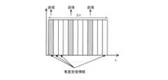
例えば、図15Bに示す長方形の1つ1つは、通信間隔Δtの間に、車載器52の記憶部に記憶された衛星受信情報を示す。衛星受信情報は、例えば、毎周期に記憶部に記憶される(t軸の1メモリごとに記憶される)。 For example, each rectangle shown in FIG. 15B indicates satellite reception information stored in the storage unit of the
車載器52は、通信間隔Δtに基づいて、路側機53に送信する記憶部の衛星受信情報のサンプリングレートを変更する。図15Bの例の場合、車載器52は、記憶部に記憶された複数の衛星受信情報のうち、斜線を付した衛星受信情報をサンプリングして路側機53に送信する。車載器52は、図15Bの斜線を付していない衛星受信情報を路側機53に送信しない。車載器52は、通信間隔Δtが長い程、衛星受信情報のサンプリングレートを長くする。 The
車載器52の移動速度が速い場合、通信間隔Δtは短くなる。そのため、記憶部に記憶される未送信の衛星受信情報のデータ量も少なくなる。 When the moving speed of the
例えば、図15Cに示すように、通信間隔Δtが短い場合、記憶部に記憶される衛星受信情報のデータ量は少なくなる。この場合、車載器52は、図15Cに示すように、記憶部に記憶されたすべての衛星受信情報をサンプリングして路側機53に送信してもよい。 For example, as shown in FIG. 15C, when the communication interval Δt is short, the amount of satellite reception information stored in the storage section is small. In this case, the
上記では、車載器52は、通信間隔Δtに基づいて、記憶部に記憶された衛星受信情報を抽出するサンプリングレートを変更し、路側機53に送信するデータの情報量を制御したが、路側機53に送信する衛星受信情報に含まれる情報を間引いてもよい。 In the above, the
図16Aおよび図16Bは、衛星受信情報の間引きの一例を説明する図である。図16Aに示す通信間隔Δtは、前回、車載器52が路側機53と通信を終了した時刻と、今回、車載器52が路側機53と通信を開始した時刻との差分を示す(図14のΔtを参照)。図16Aに示すように、路側機間の距離に極端な偏りがなければ、通信間隔Δtが長い程、車載器52を搭載した車両の平均走行速度は遅いという関係がある。つまり、通信間隔Δtが長い程、渋滞がひどいと捉えることができる。 FIGS. 16A and 16B are diagrams illustrating an example of thinning out satellite reception information. The communication interval Δt shown in FIG. 16A indicates the difference between the time when the
車載器52は、図16Aに示すように、通信間隔Δtが長い程、衛星受信情報に含まれる情報の間引き量を多くする。つまり、車載器52は、渋滞が発生している場合、衛星受信情報に含まれる情報の間引き量を多くし、路側機53に送信するデータ容量を削減する。 As shown in FIG. 16A, the
例えば、図16Bに示す長方形の1つ1つは、車載器52の記憶部に記憶された衛星受信情報を示す。衛星受信情報は、例えば、毎周期に記憶部に記憶される(t軸の1メモリごとに記憶される)。 For example, each rectangle shown in FIG. 16B indicates satellite reception information stored in the storage section of the
車載器52は、通信間隔Δtに基づいて、衛星受信情報に含まれる情報を間引く。図16Bの例の場合、車載器52は、毎周期の衛星受信情報において、白い部分の情報を間引き、斜線を付した部分の情報を衛星受信情報として路側機53に送信する。車載器52は、通信間隔Δtが長い程、衛星受信情報から間引く情報の情報量を多くする。 The
衛星受信情報から間引く情報は、例えば、衛星の幾何学的配置の良さを示すDOP(Dilution of Precision)値に影響の少ない情報でもよい。また、衛星受信情報から間引く情報は、例えば、RTK演算において、FIX解(高精度測位解)の算出に影響が少ない情報でもよい。また、衛星受信情報から間引く情報は、例えば、衛星仰角、衛星信号強度、またはサイクルスリップ等の衛星信号の品質に関する情報であってもよい。 The information to be thinned out from the satellite reception information may be, for example, information that has little effect on the DOP (Dilution of Precision) value, which indicates the goodness of the geometrical arrangement of the satellites. Further, the information to be thinned out from the satellite reception information may be, for example, information that has little influence on calculation of a FIX solution (high-precision positioning solution) in RTK calculation. Further, the information to be thinned out from the satellite reception information may be, for example, information regarding the quality of the satellite signal such as the satellite elevation angle, satellite signal strength, or cycle slip.
車載器52は、衛星受信情報のサンプリングレートの変更と、衛星受信情報の間引きとを組み合わせ、路側機53に送信する情報の情報量を制御してもよい。 The
図17は、衛星受信情報のサンプリングレートを変更しかつ衛星受信情報を間引く一例を説明する図である。車載器52は、図17に示すように、通信間隔Δtに基づいて、衛星受信情報のサンプリングレートを変更する。また、車載器52は、図17に示すように、通信間隔Δtに基づいて、衛星受信情報に含まれる情報を間引く。このように、車載器52は、通信間隔Δtに基づいて、衛星受信情報のサンプリングレートを変更し、かつ、衛星受信情報に含まれる情報を間引いて、路側機53に送信するデータの情報量を制御してもよい。 FIG. 17 is a diagram illustrating an example of changing the sampling rate of satellite reception information and thinning out the satellite reception information. As shown in FIG. 17, the
図18は、車載器52の動作例を示したフローチャートである。車載器52は、例えば、車両のエンジンが始動されてから停止されるまで、図18に示すフローチャートを実行してもよい。 FIG. 18 is a flowchart showing an example of the operation of the on-
車載器52は、路側機53の通信エリア内に位置しているか否かを判定する(S21)。 The
車載器52は、路側機53の通信エリア内に位置していないと判定した場合(S21のNo)、車両の走行速度を記憶部に記憶する(S22)。車載器52は、例えば、車両のECU(Electronic Control Unit)から、車両の走行速度を取得してもよい。 When it is determined that the vehicle-mounted
車載器52は、GNSS受信機から出力される衛星受信情報を記憶部に記憶する(S23)。車載器52は、衛星受信情報を記憶部に記憶すると、処理をS21に移行する。 The
車載器52は、S21にて、路側機53の通信エリア内に位置していると判定した場合(S21のYes)、通信間隔Δtを算出する(S24)。通信間隔Δtは、次の式(3)によって算出される。 If the
Δt=現在時間-前回の通信終了時刻 …(3) Δt=Current time - Last communication end time...(3)
車載器52は、S24にて算出した通信間隔Δtに基づいて、路側機53に送信する送信情報を決定する(S25)。例えば、車載器52は、図15で説明したように、通信間隔Δtに基づいて、記憶部から衛星受信情報を取得するサンプリングレートを変え、路側機53に送信する送信情報を決定する。または、車載器52は、図16で説明したように、通信間隔Δtに基づいて、衛星受信情報に含まれる情報を間引く量を変え、路側機53に送信する送信情報を決定する。または、車載器52は、図17で説明したように、通信間隔Δtに基づいて、記憶部から衛星受信情報を取得するサンプリングレートを変え、かつ、衛星受信情報に含まれる情報を間引く量を変え、路側機53に送信する送信情報を決定する。 The vehicle-mounted
車載器52は、DSRCデータ通信を実施する(S26)。すなわち、車載器52は、S25にて決定した送信情報を路側機53に送信する。 The
車載器52は、通信時刻を記憶部に記憶する(S27)。車載器52は、処理をステップS21に移行する。 The
以上説明したように、車載器52は、第1の路側機53(例えば、図14の左側の路側機53)との通信を終了してから第2の路側機53(例えば、図14の右側の路側機53)と通信を開始するまでの間における、GNSS受信機から出力される衛星受信情報を、第2の路側機53に送信するDSRC通信部と、前記間における時間の長さ(例えば、図14のΔt)に応じて、第2の路側機53に送信する衛星受信情報の情報量を制御するプロセッサと、を有する。これにより、例えば、渋滞が発生しても、路側機53と車載器52との通信の逼迫が抑制される。 As described above, the
なお、上記では、通信間隔Δtが長いほど、平均走行速度が遅いものと見做していた。この関係は、路側機間の距離に大きなばらつきがない場合に成立するが、現実には、数キロメートル~数十キロメートルの範囲でばらつきのある状況も発生する。路側機間の距離に大きなばらつきがある場合、通信間隔Δtが長い理由が前回通信した路側機と今回通信した路側機との間の距離が長いためであったり、通信間隔Δtが短い理由が逆に前回通信した路側機と今回通信した路側機との間の距離が短いためであったりする。しかし、このような場合であっても、GNSS受信機が一定の周期で衛星受信情報を出力する結果、Δtが長いほど多くの衛星受信情報が蓄積されるという関係は同じである。すなわち、Δtの長短の原因が、平均移動速度の差であっても路側機間の距離のばらつきであっても、Δtが長いほど多くの衛星受信情報が蓄積される。そのため、長短の原因を問わず、Δtが長いほどより多くの衛星受信情報を間引くことによって、通信帯域の逼迫を抑制することができる。なお、Δtの長短が必ずしも平均走行速度に依存しないこと、および、その場合であっても通信帯域の逼迫を抑制することができることは、以下の変形例でも同様である。 In addition, in the above, it was assumed that the longer the communication interval Δt, the slower the average traveling speed. This relationship holds true when there is no large variation in the distances between roadside machines, but in reality, situations may occur where the distances vary from several kilometers to several tens of kilometers. If there is a large variation in the distance between roadside units, the reason why the communication interval Δt is long is because the distance between the roadside unit that communicated last time and the roadside unit that communicated this time is long, or the reason that the communication interval Δt is short is the opposite. This may be because the distance between the roadside machine that communicated last time and the roadside machine that communicated this time is short. However, even in such a case, the relationship remains the same: as a result of the GNSS receiver outputting satellite reception information at a constant cycle, the longer Δt, the more satellite reception information is accumulated. That is, even if the cause of the length of Δt is a difference in average moving speed or a variation in the distance between roadside devices, the longer Δt is, the more satellite reception information is accumulated. Therefore, regardless of the cause of the length or shortness, the longer Δt is, the more satellite reception information can be thinned out, thereby suppressing the strain on the communication band. Note that the length of Δt does not necessarily depend on the average traveling speed, and even in that case, the tightness of the communication band can be suppressed, which is the same in the following modifications.
(変形例1)
路側機53は、車載器52に送信する衛星補正情報の情報量を、車載器52の通信間隔Δtに基づいて制御してもよい。衛星補正情報は、GNSS受信データの誤差を補正する情報であり、例えば、RRS(Real Reference Station)データおよびVRS(Virtual Reference Station)データである。(Modification 1)
The
例えば、車載器52は、路側機53の通信エリアにエリアインしたときに、通信間隔Δtを路側機53に送信する。路側機53は、車載器52から送信された通信間隔Δtに基づいて、車載器52に送信する衛星補正情報の情報量を制御する。 For example, when the vehicle-mounted
より具体的には、路側機53は、車載器52の通信間隔Δtに基づいて、衛星補正情報のサンプリングレートを変更し、車載器52に送信する衛星補正情報の情報量を制御する。または、車載器52は、車載器52の通信間隔Δtに基づいて、衛星補正情報に含まれる情報を間引きし、車載器52に送信する衛星補正情報の情報量を制御する。または、路側機53は、衛星補正情報のサンプリングレートの変更と間引きとを組み合わせて、車載器52に送信する衛星補正情報の情報量を制御する。 More specifically, the
このように、第2の路側機53は、車載器52がGNSS受信データを補正するための衛星補正情報を、車載器52に送信するDSRC通信部と、車載器52が第1の路側機53との通信を完了してから第2の路側機53と通信を開始するまでの間における時間の長さに応じて、車載器52に送信する衛星補正情報の情報量を制御するプロセッサと、を有する。これにより、例えば、渋滞が発生しても、路側機53と車載器52との通信の逼迫が抑制される。 In this way, the
なお、車載器52およびサーバのいずれか一方が、高精度測位演算を行ってもよい。例えば、路側機53が車載器52から衛星受信情報を受信する場合、サーバが衛星受信情報を用いて、高精度測位演算を行ってもよい。また、車載器52が路側機53から衛星補正情報を受信する場合、車載器52が路側機53から受信した衛星補正情報と、GNSS受信機から出力されるGNSS受信データとを用いて、高精度測位演算を行ってもよい。高精度測位演算の結果は、車両が車両通行帯および追越車線のどちらを走行しているかを識別する目的に用いられてもよい。 Note that either the on-
(変形例2)
車両は、例えば、高層ビルに囲まれた環境を走行する場合もある。この場合、車載器52のGNSS受信機が利用できる衛星数が少なくなり、車載器52またはサーバは、適切な測位解を得られない場合がある。そこで、車載器52または路側機53は、GNSS受信機が通信する衛星数に応じて、通信する情報の情報量を制御してもよい。(Modification 2)
For example, a vehicle may travel in an environment surrounded by high-rise buildings. In this case, the number of satellites that can be used by the GNSS receiver of the
例えば、車載器52または路側機53は、車載器52の通信間隔Δtが所定の時間より長い場合において、GNSS受信機が通信する衛星数が所定の数より小さい場合、通信する情報の情報量の削減量を小さくする。 For example, when the communication interval Δt of the
より具体的には、車載器52または路側機53は、車載器52の通信間隔Δtが所定の時間より長い場合において、GNSS受信機が通信する衛星数が10機以上の場合、情報のサンプリングレートを10秒間隔に設定する。車載器52または路側機53は、車載器52の通信間隔Δtが所定の時間より長い場合において、GNSS受信機が通信する衛星数が9機以下6機以上の場合、情報のサンプリングレートを6秒間隔に設定する。これにより、車載器52または路側機53は、GNSS受信機が通信する衛星数が少ない場合でも、サンプリングレートを上げることにより適切な測位解が得られる。 More specifically, when the communication interval Δt of the
衛星数がより少ない場合、車載器52またはサーバは、適切なFIX解を算出できない場合がある。この場合、車載器52または路側機53は、通信する情報の情報量の削減量を、逆に大きくしてもよい。例えば、車載器52または路側機53は、車載器52の通信間隔Δtが所定の時間より長い場合において、GNSS受信機が通信する衛星数が5機以下の場合、情報のサンプリングレートを20秒間隔に設定してもよい。 When the number of satellites is smaller, the
なお、車載器52または路側機53は、車載器52の平均走行速度が所定の速度より遅い場合において、GNSS受信機が通信する衛星数が所定の数より小さい場合、通信する情報の情報量の削減量を小さくしてもよい。 Note that when the average traveling speed of the
(変形例3)
上記第2の実施の形態では、車載器52は、通信間隔Δtに基づいて、路側機53に送信する衛星受信情報の情報量を制御したが、これに限られない。車載器52は、非通信エリアにおける車両の平均走行速度に基づいて、路側機53に送信する衛星受信情報の情報量を制御してもよい。また、車載器52は、GNSS受信機が通信する衛星数に基づいて、路側機53に送信する衛星受信情報の情報量を制御してもよい。(Modification 3)
In the second embodiment, the vehicle-mounted
図19は、車載器52の動作例を示したフローチャートである。車載器52は、例えば、車両のエンジンが始動されてから停止されるまで、図19に示すフローチャートを実行してもよい。 FIG. 19 is a flowchart showing an example of the operation of the on-
車載器52は、GNSS受信機から出力されるGNSS受信データを取得する(S81)。 The
車載器52は、車載器52を搭載している車両の走行速度を算出する(S82)。例えば、車載器52は、GNSS受信データから搬送波のドップラーシフト量を計算し、車両の走行速度を算出してもよい。または、車載器52は、コード測位を実行し、前回のコード測位解と今回のコード測位解とから車両の走行速度を算出してもよい。なお、コード測位解は、高精度測位解より簡易な計算で得ることのできる粗い測位解である。または、車載器52は、車速パルス信号から、車両の走行速度を算出してもよい。 The on-
車載器52は、S82にて算出した走行速度が閾値以上であるか否かを判定する(S83)。 The on-
車載器52は、S82にて算出した走行速度が閾値以上であると判定した場合(S83のYes)、車両は通常走行(例えば、渋滞が無いときの走行)をしていると判定し、RTK演算に用いる衛星を決定する(S84)。例えば、車載器52は、GNSS受信データに含まれる衛星の仰角と信号強度情報とにより、RTK演算に用いる衛星を決定する。 If the vehicle-mounted
車載器52は、RTK演算に用いるGNSS受信データを第1サンプリング間隔で記憶部に記憶する(S85)。なお、第1サンプリング間隔(St1)と、S90で説明する第2サンプリング間隔(St2)と、S92で説明する第3サンプリング間隔(St3)と、S93で説明する第4サンプリング間隔(St4)との間には、下記の式(4)の関係がある。 The
St4>St2>St1=St3 …(4) St4>St2>St1=St3...(4)
車載器52は、路側機53の通信エリアに位置しているか否かを判定する(S86)。 The
車載器52は、路側機53の通信エリアに位置していると判定した場合(S86のYes)、記憶部に記憶したGNSS受信データを路側機53へ送信する(S87)。 When the
一方、車載器52は、路側機53の通信エリアに位置していないと判定した場合(S86のNo)、処理をS81に移行する。 On the other hand, when it is determined that the
車載器52は、S83にて走行速度が閾値以上でないと判定した場合(S83のNo)、車両は低速走行(例えば、渋滞が生じたときの走行)をしていると判定し、RTK演算に用いる衛星を決定する(S88)。 If the vehicle-mounted
車載器52は、決定した衛星の数が第1閾値以上であるか否かを判定する(S89)。 The
車載器52は、決定した衛星の数が第1閾値以上であると判定した場合(S89のYes)、RTK演算に用いるGNSS受信データを第2サンプリング間隔で記憶部に記憶する(S90)。すなわち、車載器52は、S88にて決定した衛星の数が、RTK演算において測位解を得るのに十分な数である場合、第1サンプリング間隔より大きい第2サンプリング間隔でGNSS受信データを記憶部に記憶する。つまり、車載器52は、車両が低速走行していると判定した場合、路側機53に送信するGNSS受信データを削減するため、第1サンプリング間隔より大きい第2サンプリング間隔でGNSS受信データを記憶部に記憶する。 When the vehicle-mounted
一方、車載器52は、決定した衛星の数が第1閾値以上でないと判定した場合(S89のNo)、決定した衛星の数が第2閾値以上であるか否かを判定する(S91)。なお、第2閾値は、S89の第1閾値より小さい値である。 On the other hand, when the vehicle-mounted
車載器52は、決定した衛星の数が第2閾値以上であると判定した場合(S91のYes)、RTK演算に用いるGNSS受信データを第3サンプリング間隔で記憶部に記憶する(S92)。すなわち、車載器52は、S88にて決定した衛星の数が、RTK演算において測位解を得るのに十分な数であるが、第1閾値より小さい場合、第1サンプリング間隔と同じ第3サンプリング間隔でGNSS受信データを記憶部に記憶する。つまり、車載器52は、衛星数が第1閾値より小さく第2閾値以上の場合、GNSS受信データのサンプリング間隔を小さくし(サンプリングレートを上げ)、RTK演算における測位解の精度を向上する。 When the vehicle-mounted
一方、車載器52は、決定した衛星の数が第2閾値以上でないと判定した場合(S91のNo)、RTK演算に用いるGNSS受信データを第4サンプリング間隔で記憶部に記憶する(S93)。すなわち、車載器52は、S88にて決定した衛星の数が、RTK演算において測位解を得るのに十分な数でない場合、第2サンプリング間隔より大きい第4サンプリング間隔でGNSS受信データを記憶部に記憶する。つまり、車載器52は、S88にて決定した衛星の数が、RTK演算において測位解を得るのに十分な数でない場合、路側機53に送信するGNSS受信データの情報量をより少なくする。 On the other hand, when the vehicle-mounted
このように、車載器52は、第1の路側機53との通信を終了してから第2の路側機53と通信を開始するまでの間における、GNSS受信機から出力される衛星受信情報を、第2の路側機53に送信するDSRC通信部と、車載器52を搭載した車両の前記間における走行速度に応じて、第2の路側機53に送信する衛星受信情報の情報量を制御するプロセッサと、を有する。これにより、例えば、渋滞が発生しても、路側機53と車載器52との通信の逼迫が抑制される。 In this way, the
なお、変形例3では、GNSS受信機から出力されるGNSS受信データのサンプリングレートを変更し、記憶部に記憶したがこれに限られない。GNSS受信機から出力されるGNSS受信データを記憶部に記憶し、記憶部から抽出するGNSS受信データのサンプリングレートを変更してもよい。 Note that in
また、図19のS91において、車載器52は、決定した衛星の数が第2閾値以上でないと判定した場合(S91のNo)、GNSS受信データをサンプリングしなくてもよい。すなわち、車載器52は、GNSS受信データを路側機53に送信しなくてもよい。 Moreover, in S91 of FIG. 19, when the vehicle-mounted
また、変形例3では、車載器52について説明したが、路側機53も同様に、走行速度に基づいて、通信する情報の情報量を制御してもよい。路側機53は、車両の走行速度に基づいて情報を間引いてもよいし、サンプリングレートの変更と間引きとを組み合わせてもよい。 Further, in the third modification, the on-
すなわち、第2の路側機53は、車載器52がGNSS受信データを補正するための衛星補正情報を、車載器52に送信するDSRC通信部と、車載器52が第1の路側機53との通信を完了してから第2の路側機53と通信を開始するまでの間における、車載器52を搭載した車両の走行速度に応じて、車載器52に送信する衛星補正情報の情報量を制御するプロセッサと、を有する。これにより、路側機53と車載器52との通信の逼迫が抑制される。 That is, the
(変形例4)
上記第2の実施の形態では、車載器52は、記憶部に記憶された衛星受信情報を抽出するサンプリングレートを変更したがこれに限られない。車載器52は、GNSS受信機から出力されるGNSS受信データを抽出するサンプリングレートを変更し、抽出したGNSS受信データを記憶部に記憶してもよい。(Modification 4)
In the second embodiment, the
(第3の実施の形態)
第3の実施の形態では、路側機が車載器に基準局データ(RTCM:Radio Technical Commission For Maritime Service)を配信し、車載器側でRTK演算を行う。(Third embodiment)
In the third embodiment, the roadside device delivers reference station data (RTCM: Radio Technical Commission For Maritime Service) to the onboard device, and the onboard device performs RTK calculation.
基準局データは、車載器の走行経路をカバーするRRSデータまたはVRSデータである。基準局データを配信する基準局と車載器との距離は短い程よい。以下では、基準局データ(RRSデータまたはVRSデータ)を補正情報と呼ぶことがある。 The reference station data is RRS data or VRS data that covers the travel route of the onboard equipment. The shorter the distance between the reference station that distributes reference station data and the onboard equipment, the better. Below, the reference station data (RRS data or VRS data) may be referred to as correction information.
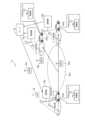
図20は、第3の実施の形態に係る測位システム61の構成例を示した図である。図20に示すように、測位システム61は、車両A41~A43に搭載される車載器62a~62cと、路側機63a~63cと、サーバ64と、RRS65a,65bと、VRS66a,66bと、を有している。車載器62a~62cのブロック構成は、図4で説明した車載器3のブロック構成と同様であり、その説明を省略する。路側機63a~63cのブロック構成は、図5で説明した路側機4のブロック構成と同様であり、その説明を省略する。サーバ64のブロック構成は、図6で説明したサーバ5のブロック構成と同様であり、その説明を省略する。 FIG. 20 is a diagram showing a configuration example of a
以下では、車載器62a~62cを区別しない場合、車載器62と記載する。路側機63a~63cを区別しない場合、路側機63と記載する。RRS65a,65bを区別しない場合、RRS65と記載する。VRS66a,66bを区別しない場合、VRS66と記載する。RRS65およびVRS66は、基準局と呼ばれてもよい。 Below, when the on-
車載器62および路側機63は、DSRCに基づいた双方向通信を行う。車載器62は、路側機63が形成する通信エリア内において、路側機63と通信する。 The on-vehicle device 62 and the roadside device 63 perform two-way communication based on DSRC. The onboard device 62 communicates with the roadside device 63 within a communication area formed by the roadside device 63.
車両A41~A43は、GNSS受信機(図示せず)を搭載している。車載器62a~62cの各々は、GNSS受信機から出力されるGNSS受信データを受信する。 Vehicles A41 to A43 are equipped with GNSS receivers (not shown). Each of the
図20には、路側機63の通信エリアが形成されていない非通信エリアX11が示してある。非通信エリアX11には、路側機63aの通信エリアを通過し、路側機63cの通信エリアを通過する車両の走行経路が含まれる。また、非通信エリアX11には、路側機63bの通信エリアを通過し、路側機63cの通信エリアを通過する車両の走行経路が含まれる。車載器62は、非通信エリアX11においては、路側機63とDSRCに基づく通信を行うことができない。 FIG. 20 shows a non-communication area X11 in which a communication area for the roadside device 63 is not formed. The non-communication area X11 includes a travel route of a vehicle that passes through the communication area of the
車載器62は、GNSS受信データを用いて、コード測位解を算出する。車載器62は、算出したコード測位解を、路側機63を介して、サーバ64に送信する。また、車載器62は、GNSS受信データと、路側機63から配信される補正情報とを用いてRTK演算を行い、高精度測位解を算出する。 The onboard device 62 uses the GNSS received data to calculate a code positioning solution. The onboard device 62 transmits the calculated code positioning solution to the
サーバ64は、車載器62から送信されたコード測位解の分布(位置の分布)の中心を算出する。サーバ64は、算出した中心に最も近いRRS65またはVRS66の補正情報を取得する。例えば、図20の例の場合、サーバ64は、RRS65aの補正情報を取得する。言い換えれば、サーバ64は、DSRC通信ができない走行経路の分布の中心付近の補正情報を取得する。サーバ64は、取得した補正情報を、路側機63を介して車載器62に配信する。 The
以下、測位システム61の動作例を説明する。まず、非通信エリアX11におけるコード測位解のサーバ64へのアップロードについて説明する。 An example of the operation of the
図20に示した車両A41は、路側機63aの通信エリアと、非通信エリアX11とを通過し、路側機63cの通信エリアにエリアインする。車両A41の車載器62aは、非通信エリアX11を走行している間、GNSS受信機から出力されるGNSS受信データを用いて、コード測位解を算出し、算出したコード測位解を記憶部に記憶する。すなわち、車載器62aは、路側機63aとの通信を終了してから、路側機63cと通信を開始するまでの間における走行経路のコード測位解を算出し、記憶部に記憶する。 The vehicle A41 shown in FIG. 20 passes through the communication area of the
車載器62aは、路側機63cの通信エリアにエリアインすると、記憶部に記憶したコード測位解を路側機63cに送信する。路側機63cは、車載器62aから送信されたコード測位解をサーバ64に送信する。 When the vehicle-mounted
同様に、図20に示した車両A42は、路側機63bの通信エリアと、非通信エリアX11とを通過し、路側機63cの通信エリアにエリアインする。車両A42の車載器62bは、非通信エリアX11を走行している間、GNSS受信機から出力されるGNSS受信データを用いて、コード測位解を算出し、算出したコード測位解を記憶部に記憶する。すなわち、車載器62bは、路側機63bとの通信を終了してから、路側機63cと通信を開始するまでの間における走行経路のコード測位解を算出し、記憶部に記憶する。 Similarly, the vehicle A42 shown in FIG. 20 passes through the communication area of the
車載器62bは、路側機63cの通信エリアにエリアインすると、記憶部に記憶したコード測位解を路側機63cに送信する。路側機63cは、車載器62bから送信されたコード測位解をサーバ64に送信する。 When the vehicle-mounted
このようにして、車載器62a,62bの非通信エリアX11におけるコード測位解は、サーバ64にアップロードされる。 In this way, the code positioning solutions of the
次に、シーケンス図を用いて、車載器62cにおけるRTK演算までの動作例について説明する。 Next, an example of the operation up to RTK calculation in the
図21は、測位システム61の動作例を説明するシーケンス図である。以下では、車載器62a,62bは、路側機63cの通信エリアを通過し、サーバ64に車載器62a,62bのコード測位解をアップロードしているとする。 FIG. 21 is a sequence diagram illustrating an example of the operation of the
また、以下では、車載器62cは、路側機63aの通信エリアと、非通信エリアX11とを通過し、路側機63cの通信エリアにエリアインする。車載器62cは、現在、路側機63aの通信エリア内を移動しているとする。 Moreover, below, the
車載器62cは、路側機63aの通信エリア外か否かを判定する(S31)。車載器62cは、路側機63cの通信エリア外でないと判定した場合(S31のNo)、S31の処理を繰り返す。 The
一方、車載器62cは、路側機63aの通信エリア外と判定した場合(S31のYes)、GNSS受信機から出力されるGNSS受信データを記憶部に記憶する(S32)。つまり、車載器62cは、路側機63aの通信エリアを出て、非通信エリアX11にエリアインした場合、GNSS受信機から出力されるGNSS受信データを記憶部に記憶する。 On the other hand, when the vehicle-mounted
車載器62cは、GNSS受信データを用いて、コード測位解を算出し、記憶部に記憶する(S33)。 The
車載器62cは、次の路側機である路側機63cの通信エリアにエリアインしたか否かを判定する(S34)。 The
車載器62cは、路側機63cの通信エリアにエリアインしていないと判定した場合(S34のNo)、処理をS32に移行する。 If the on-
一方、車載器62cは、路側機63cの通信エリアにエリアインしたと判定した場合(S34のYes)、記憶部に記憶したコード測位解を路側機63cに送信する(S35)。 On the other hand, when the vehicle-mounted
路側機63cは、S35にて送信されたコード測位解をサーバ64へ送信する(S36)。 The
サーバ64は、S36にて送信された車載器62cのコード測位解および車載器62a,62bを含む他の車載器のコード測位解の分布の中心を算出する(S37)。 The
サーバ64は、S37にて算出した中心位置に最も近いRSS65またはVSR66を選択し、選択したRSS65またはVSR66の補正情報を路側機63cへ送信する(S38)。 The
路側機63cは、S38にて送信された補正情報を車載器62cへ送信する(S39)。すなわち、路側機63cは、非通信エリアX11を通過してきた車載器62cに対し、非通信エリアX11における補正情報を送信する。 The
車載器62cは、S32にて記憶部に記憶したGNSS受信データと、S39にて送信された補正情報とを用いて、RTK演算により、非通信エリアX11における高精度測位解を算出する(S40)。 The
なお、路側機63a,63bも路側機63cと同様に、補正情報を配信する。路側機63a,63bの通信エリアを通過する車載器は、路側機63a,63bから配信される補正情報と、路側機63a,63bの通信エリアにエリアインする前に通過した非通信エリアにおけるGNSS受信データとから、非通信エリアの高精度測位解を算出する。 Note that the
また、図21のS37において、サーバ64は、車載器62cのコード測位解および車載器62a,62bを含む他の車載器のコード測位解の分布の中心を算出したが、これに限られない。サーバ64は、車載器62cを除く、車載器62a,62bを含む他の車載器のコード測位解の分布の中心を算出してもよい。 Moreover, in S37 of FIG. 21, the
以上説明したように、車載器62cは、路側機63a(または路側機63b)との通信を終了してから路側機63cと通信を開始するまでの間における補正情報を、路側機63cから受信するDSRC通信部と、前記間におけるGNSS受信データと、補正情報とを用いて、前記間における高精度測位解を算出するプロセッサと、を備える。これにより、車載器62cは、非通信エリアX11における、高精度測位解を算出できる。 As explained above, the
また、サーバ64は、車載器62a,62bがGNSS受信データを用いて、路側機63a,63bとの通信を終了してから路側機63cと通信を開始するまでの間に算出したコード測位解を、路側機63cを介して受信する通信部と、コード測位解に基づいて、前記間における補正情報を出力する基準局を選択するプロセッサと、選択した基準局の補正情報を、路側機63cを介して車載器62cに送信する送信部と、を備える。これにより、車載器62cは、非通信エリアX11における、高精度測位解を算出できる。 In addition, the
なお、実施の形態では、車載器62a、62b、62cがすべて異なる車載器であるものとして説明したが、少なくとも車載器62aと車載器62cは同一の車載器でも良い。この車載器は、すでに通過した非通信エリアX11におけるコード測位解を記録しているので、車載器62a、62c両方の位置におけるコード測位解を記録しているためである。また、分布の中心は最低2つの位置におけるコード測位解が得られれば算出できるため、車載器62aと62cが同一の車載器である場合には、他の車載器である車載器62bからのコード測位解を用いなくともよい。このようにすることで、交通量の少ない道路においても、非通信エリア11における高精度測位解を算出することができる。 In the embodiment, the on-
また、第3の実施の形態では、サーバ64は、コード測位解をアップロードした車載器62cより前にアップロードされた他の車載器62a,62bのコード測位解も用い、コード測位解の分布の中心を算出したが、これに限られない。サーバ64は、他の車載器62a,62bのコード測位解を用いず、コード測位解をアップロードした車載器62cのコード測位解を用いて、コード測位解の分布の中心を算出してもよい。そして、サーバ64は、算出した中心にもっと近い基準局を選択し、選択した基準局の補正情報を車載器62cに送信してもよい。車載器62cが、すでに通過した非通信エリアX11におけるコード測位解を2つ以上の位置で算出し、記録していれば、それらのコード測位解を基に分布の中心を求めることができるためである。分布の中心は、最低2つの位置におけるコード測位解が得られれば算出できるため、車載器62cが2つ以上の位置で算出されたコード測位解をサーバ64にアップロードする構成であれば、サーバ64は、他の車載器である車載器62a,62bのコード測位解を用いなくとも分布の中心を算出できる。このようにすることで、交通量の少ない道路においても、非通信エリア11における高精度測位解を算出することができる。 In the third embodiment, the
(第4の実施の形態)
第3の実施の形態では、車載器は、通過した非通信エリアにおける高精度測位解を事後的に算出する。第4の実施の形態では、車載器は、通過する非通信エリアにおける高精度測位解をリアルタイムに(非通信エリアの通過中に)算出する。(Fourth embodiment)
In the third embodiment, the on-vehicle device calculates a high-precision positioning solution after the fact in a non-communication area through which the vehicle has passed. In the fourth embodiment, the vehicle-mounted device calculates a high-precision positioning solution in a non-communication area through which it passes in real time (while passing through the non-communication area).
図22は、第4の実施の形態に係る測位システム71の構成例を示した図である。図22に示すように、測位システム71は、車両A51~A53に搭載される車載器72a~72cと、路側機73a~73cと、サーバ74と、RRS75a~75cと、VRS76と、を有している。車載器72a~72cのブロック構成は、図4で説明した車載器3のブロック構成と同様であり、その説明を省略する。路側機73a~73cのブロック構成は、図5で説明した路側機4のブロック構成と同様であり、その説明を省略する。サーバ74のブロック構成は、図6で説明したサーバ5のブロック構成と同様であり、その説明を省略する。 FIG. 22 is a diagram showing a configuration example of a
以下では、車載器72a~72cを区別しない場合、車載器72と記載する。路側機73a~73cを区別しない場合、路側機73と記載する。RRS75a~75cを区別しない場合、RRS75と記載する。 In the following, when the on-
車載器72および路側機73は、DSRCに基づいた双方向通信を行う。車載器72は、路側機73が形成する通信エリア内において、路側機73と通信する。 The on-vehicle device 72 and the roadside device 73 perform two-way communication based on DSRC. The on-vehicle device 72 communicates with the roadside device 73 within a communication area formed by the roadside device 73.
車両A51~A53は、GNSS受信機(図示せず)を搭載している。車載器72a~72cの各々は、GNSS受信機から出力されるGNSS受信データを受信する。 Vehicles A51 to A53 are equipped with GNSS receivers (not shown). Each of the
図22には、路側機73の通信エリアが形成されていない非通信エリアX21が示してある。非通信エリアX21には、路側機73aの通信エリアを通過し、路側機73bの通信エリアを通過する車両の走行経路が含まれる。また、非通信エリアX21には、路側機73aの通信エリアを通過し、路側機73cの通信エリアを通過する車両の走行経路が含まれる。車載器72は、非通信エリアX21においては、路側機73とDSRCに基づく通信を行うことができない。 FIG. 22 shows a non-communication area X21 in which a communication area for the roadside device 73 is not formed. The non-communication area X21 includes a travel route of a vehicle that passes through the communication area of the
車載器72は、GNSS受信データを用いて、コード測位解を算出する。車載器72は、算出したコード測位解を、路側機73を介して、サーバ74に送信する。また、車載器72は、GNSS受信データと、路側機73から配信される補正情報とを用いてRTK演算を行い、高精度測位解を算出する。 The onboard device 72 uses the GNSS received data to calculate a code positioning solution. The onboard device 72 transmits the calculated code positioning solution to the
サーバ74は、車載器72から送信されたコード測位解の分布(位置の分布)の中心を算出する。サーバ74は、算出した中心に最も近いRRS75またはVRS76の補正情報を取得する。例えば、図20の例の場合、サーバ74は、RRS75aの補正情報を取得する。言い換えれば、サーバ74は、DSRC通信ができない走行経路の分布の中心付近の補正情報を取得する。サーバ74は、取得した補正情報を、路側機73を介して車載器72に配信する。 The
以下、測位システム71の動作例を説明する。まず、非通信エリアX21におけるコード測位解のサーバ74へのアップロードについて説明する。 An example of the operation of the
図22に示した車両A52は、路側機73aの通信エリアと、非通信エリアX21とを通過し、路側機73bの通信エリアにエリアインする。車両A52の車載器72bは、非通信エリアX21を走行している間、GNSS受信機から出力されるGNSS受信データを用いて、コード測位解を算出し、算出したコード測位解を記憶部に記憶する。すなわち、車載器72bは、路側機73aとの通信を終了してから、路側機73bと通信を開始するまでの間における走行経路のコード測位解を算出し、記憶部に記憶する。 The vehicle A52 shown in FIG. 22 passes through the communication area of the
車載器72bは、路側機73bの通信エリアにエリアインすると、記憶部に記憶したコード測位解を路側機73bに送信する。路側機73bは、車載器72bから送信されたコード測位解をサーバ74に送信する。 When the vehicle-mounted device 72b enters the communication area of the
同様に、図22に示した車両A53は、路側機73aの通信エリアと、非通信エリアX21とを通過し、路側機73cの通信エリアにエリアインする。車両A53の車載器72cは、非通信エリアX21を走行している間、GNSS受信機から出力されるGNSS受信データを用いて、コード測位解を算出し、算出したコード測位解を記憶部に記憶する。すなわち、車載器72cは、路側機73aとの通信を終了してから、路側機73cと通信を開始するまでの間における走行経路のコード測位解を算出し、記憶部に記憶する。 Similarly, the vehicle A53 shown in FIG. 22 passes through the communication area of the
車載器72cは、路側機73cの通信エリアにエリアインすると、記憶部に記憶したコード測位解を路側機73cに送信する。路側機73cは、車載器72cから送信されたコード測位解をサーバ74に送信する。 When the vehicle-mounted device 72c enters the communication area of the
このようにして、車載器72b,72cの非通信エリアX21におけるコード測位解は、サーバ74にアップロードされる。 In this way, the code positioning solutions of the onboard devices 72b and 72c in the non-communication area X21 are uploaded to the
次に、シーケンス図を用いて、車載器72aにおけるRTK演算までの動作例について説明する。 Next, an example of the operation up to RTK calculation in the
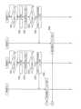
図23Aおよび図23Bは、測位システム71の動作例を説明するシーケンス図である。以下では、車載器72bは、路側機73aの通信エリアにエリアインし、非通信エリアX21を通過して、路側機73bの通信エリアにエリアインするとする。車載器72bは、路側機73aの通信エリアにエリアインしたとき、路側機73aを経由して、サーバ74から非通信エリアX21における補正情報を受信する。 23A and 23B are sequence diagrams illustrating an example of the operation of the
また、以下では、車載器72cは、路側機73aの通信エリアにエリアインし、非通信エリアX21を通過して、路側機73cの通信エリアにエリアインするとする。車載器72cは、路側機73aの通信エリアにエリアインしたとき、路側機73aを経由して、サーバ74から非通信エリアX21における補正情報を受信する。 In the following, it is assumed that the on-vehicle device 72c enters the communication area of the
図23Bに示すように、車載器72bは、路側機73aの通信エリア外か否かを判定する(S51)。車載器72bは、路側機73aの通信エリア外でないと判定した場合(S51のNo)、S51の処理を繰り返す。 As shown in FIG. 23B, the on-vehicle device 72b determines whether it is outside the communication area of the
一方、車載器72bは、路側機73aの通信エリア外と判定した場合(S51のYes)、路側機73aから受信した非通信エリアX21における補正情報と、GNSS受信機から出力されるGNSS受信データとを用いてRTK演算を行う(S52)。つまり、車載器72bは、路側機73aの通信エリアを出て、非通信エリアX21にエリアインした場合、路側機73aから受信した非通信エリアX21における補正情報を用いて、非通信エリアX21における高精度測位解をリアルタイムに算出する。 On the other hand, when the onboard device 72b determines that it is outside the communication area of the
車載器72bは、GNSS受信機から出力されるGNSS受信データを用いて、コード測位解を算出し、記憶部に記憶する(S53)。つまり、車載器72bは、路側機73aの通信エリアを出て、非通信エリアX21にエリアインした場合、コード測位解を算出して記憶部に記憶する。 The onboard device 72b uses the GNSS reception data output from the GNSS receiver to calculate a code positioning solution and stores it in the storage unit (S53). That is, when the vehicle-mounted device 72b leaves the communication area of the
なお、ステップS52で算出された高精度測位解を、ステップS53で算出されるコード測位解の代わりに記憶部に記憶しても良い。ただし、ステップS52において算出される高精度測位解は、過去の時点における測位解であるため、ステップS53で算出されるコード測位解の方が車載器72bの最新の位置を反映している可能性が高い。したがって、車載器72bが高速で移動している場合など、位置が変化し易い状況ではコード測位解を、渋滞など位置が変化しにくい状況では高精度測位解を記憶部に記憶するとしてもよい。なお、ステップS52にて高精度測位解を記憶した場合、以後のステップでもコード測位解に代えて高精度測位解を用いてもよい。 Note that the high-precision positioning solution calculated in step S52 may be stored in the storage unit instead of the code positioning solution calculated in step S53. However, since the high-precision positioning solution calculated in step S52 is a positioning solution at a past point in time, there is a possibility that the code positioning solution calculated in step S53 reflects the latest position of the onboard device 72b. is high. Therefore, the code positioning solution may be stored in the storage unit in a situation where the position is likely to change, such as when the onboard device 72b is moving at high speed, and the high-precision positioning solution may be stored in the storage unit, in a situation where the position is difficult to change, such as in traffic jams. Note that when the high-precision positioning solution is stored in step S52, the high-precision positioning solution may be used instead of the code positioning solution in subsequent steps as well.
車載器72bは、次の路側機である路側機73bの通信エリアにエリアインしたか否かを判定する(S54)。 The onboard device 72b determines whether or not it has entered the communication area of the next roadside device, the
車載器72bは、路側機73bの通信エリアにエリアインしていないと判定した場合(S54のNo)、処理をS52に移行する。 If the onboard device 72b determines that it is not in the communication area of the
一方、車載器72bは、路側機73bの通信エリアにエリアインしたと判定した場合(S54のYes)、記憶部に記憶したコード測位解を路側機73bに送信する(S55)。 On the other hand, when the vehicle-mounted device 72b determines that it has entered the communication area of the
路側機73bは、S55にて送信されたコード測位解をサーバ74へ送信する(S56)。 The
図23Bに示すように、車載器72cは、路側機73aの通信エリア外か否かを判定する(S61)。車載器72cは、路側機73aの通信エリア外でないと判定した場合(S61のNo)、S61の処理を繰り返す。 As shown in FIG. 23B, the on-vehicle device 72c determines whether it is outside the communication area of the
一方、車載器72bは、路側機73aの通信エリア外と判定した場合(S61のYes)、路側機73aから受信した非通信エリアX21における補正情報と、GNSS受信機から出力されるGNSS受信データとを用いてRTK演算を行う(S62)。つまり、車載器72cは、路側機73aの通信エリアを出て、非通信エリアX21にエリアインした場合、路側機73aから受信した非通信エリアX21における補正情報を用いて、非通信エリアX21における高精度測位解をリアルタイムに算出する。 On the other hand, when the onboard device 72b determines that it is outside the communication area of the
車載器72cは、GNSS受信機から出力されるGNSS受信データを用いて、コード測位解を算出し、記憶部に記憶する(S63)。つまり、車載器72cは、路側機73aの通信エリアを出て、非通信エリアX21にエリアインした場合、コード測位解を算出して記憶部に記憶する。 The onboard device 72c calculates a code positioning solution using the GNSS reception data output from the GNSS receiver, and stores it in the storage unit (S63). That is, when the vehicle-mounted device 72c leaves the communication area of the
なお、ステップS62で算出された高精度測位解を、ステップS63で算出されるコード測位解の代わりに記憶部に記憶しても良い。ただし、ステップS62において算出される高精度測位解は、過去の時点における測位解であるため、ステップS63で算出されるコード測位解の方が車載器72cの最新の位置を反映している可能性が高い。したがって、車載器72cが高速で移動している場合など、位置が変化し易い状況ではコード測位解を、渋滞など位置が変化しにくい状況では高精度測位解を記憶部に記憶するとしてもよい。なお、ステップS62にて高精度測位解を記憶した場合、以後のステップでもコード測位解に代えて高精度測位解を用いてもよい。 Note that the high-precision positioning solution calculated in step S62 may be stored in the storage unit instead of the code positioning solution calculated in step S63. However, since the high-precision positioning solution calculated in step S62 is a positioning solution at a past point in time, there is a possibility that the code positioning solution calculated in step S63 reflects the latest position of the onboard device 72c. is high. Therefore, the code positioning solution may be stored in the storage unit in a situation where the location is likely to change, such as when the onboard device 72c is moving at high speed, and the high-precision positioning solution may be stored in the storage unit, in a situation where the location is difficult to change, such as in traffic jams. Note that when the high-precision positioning solution is stored in step S62, the high-precision positioning solution may be used instead of the code positioning solution in subsequent steps as well.
車載器72cは、次の路側機である路側機73cの通信エリアにエリアインしたか否かを判定する(S64)。 The onboard device 72c determines whether or not it has entered the communication area of the next roadside device, the
車載器72cは、路側機73cの通信エリアにエリアインしていないと判定した場合(S64のNo)、処理をS62に移行する。 If the on-vehicle device 72c determines that it is not in the communication area of the
一方、車載器72cは、路側機73cの通信エリアにエリアインしたと判定した場合(S64のYes)、記憶部に記憶したコード測位解を路側機73cに送信する(S65)。 On the other hand, when the vehicle-mounted device 72c determines that it has entered the communication area of the
路側機73cは、S65にて送信されたコード測位解をサーバ74へ送信する(S66)。 The
図23Aに示すように、サーバ74は、他の車載器のコード測位解の分布の中心を算出する(S71)。他の車載器のコード測位解には、図23BのS56,S66にて送信された車載器72b,72cのコード測位解が含まれる。 As shown in FIG. 23A, the
サーバ74は、S71にて算出した中心位置に最も近いRSS75またはVSR76を選択し、選択したRSS75またはVSR76の補正情報を路側機73aへ送信する(S72)。 The
路側機73aは、S72にて送信された補正情報を車載器72aへ送信する(S73)。すなわち、路側機73aは、路側機73aの通信エリアを通過した後、非通信エリアX21を通過する車載器72aに対し、非通信エリアX21における補正情報を送信する。 The
車載器72aは、GNSS受信機から出力されるGNSS受信データと、S73にて送信された補正情報とを用いて、RTK演算により、非通信エリアX21における高精度測位解を算出する(S74)。すなわち、車載器72aは、リアルタイムに非通信エリアにおける高精度測位解を算出する。 The
なお、図23Aのシーケンス図では、車載器72aが、路側機73aの通信エリアにエリアインする前の処理について説明を省略している。 In addition, in the sequence diagram of FIG. 23A, description of the process before the
以上説明したように、車載器72aは、路側機73aとの通信を終了してから路側機73b(または路側機73c)と通信を開始するまでの間における補正情報を、路側機73aから受信するDSRC通信部と、前記間におけるGNSS受信データと、補正情報とを用いて、前記間における高精度測位解を算出するプロセッサと、を備える。これにより、車載器72aは、非通信エリアX21における、高精度測位解を算出できる。 As explained above, the on-
また、サーバ74は、車載器72b,72cが衛星から受信したGNSS受信データを用いて、路側機73aとの通信を終了してから路側機73b,73cと通信を開始するまでの間に算出したコード測位解を、路側機73b,73cを介して受信する通信部と、コード測位解に基づいて、前記間における補正情報を出力する基準局を選択するプロセッサと、選択した基準局の補正情報を、路側機73aを介して車載器72aに送信する送信部と、を備える。これにより、車載器72aは、非通信エリアX21における、高精度測位解を算出できる。 In addition, the
上述の実施の形態においては、各構成要素に用いる「・・・部」という表記は、「・・・回路(circuitry)」、「・・・デバイス」、「・・・ユニット」、又は、「・・・モジュール」といった他の表記に置換されてもよい。 In the embodiments described above, the notation "... section" used for each component is "... circuit (circuitry)," "... device," "... unit," or "... unit." ... module" may be substituted with other notation.
以上、図面を参照しながら実施の形態について説明したが、本開示はかかる例に限定されない。当業者であれば、特許請求の範囲に記載された範疇において、各種の変更例または修正例に想到し得ることは明らかである。そのような変更例または修正例についても、本開示の技術的範囲に属するものと了解される。また、本開示の趣旨を逸脱しない範囲において、実施の形態における各構成要素は任意に組み合わされてよい。 Although the embodiments have been described above with reference to the drawings, the present disclosure is not limited to such examples. It is clear that those skilled in the art can come up with various changes and modifications within the scope of the claims. It is understood that such changes or modifications also fall within the technical scope of the present disclosure. Further, each component in the embodiments may be arbitrarily combined without departing from the spirit of the present disclosure.
本開示はソフトウェア、ハードウェア、又は、ハードウェアと連携したソフトウェアで実現することが可能である。上記実施の形態の説明に用いた各機能ブロックは、部分的に又は全体的に、集積回路であるLSIとして実現され、上記実施の形態で説明した各プロセスは、部分的に又は全体的に、一つのLSI又はLSIの組み合わせによって制御されてもよい。LSIは個々のチップから構成されてもよいし、機能ブロックの一部または全てを含むように一つのチップから構成されてもよい。LSIはデータの入力と出力を備えてもよい。LSIは、集積度の違いにより、IC、システムLSI、スーパーLSI、ウルトラLSIと呼称されることもある。 The present disclosure can be implemented with software, hardware, or software in conjunction with hardware. Each functional block used in the description of the above embodiment is partially or entirely realized as an LSI that is an integrated circuit, and each process explained in the above embodiment is partially or entirely realized as an LSI, which is an integrated circuit. It may be controlled by one LSI or a combination of LSIs. The LSI may be composed of individual chips, or may be composed of a single chip that includes some or all of the functional blocks. The LSI may include data input and output. LSIs are sometimes called ICs, system LSIs, super LSIs, and ultra LSIs depending on the degree of integration.
集積回路化の手法はLSIに限るものではなく、専用回路、汎用プロセッサ又は専用プロセッサで実現してもよい。また、LSI製造後に、プログラムすることが可能なFPGAや、LSI内部の回路セルの接続や設定を再構成可能なリコンフィギュラブル・プロセッサを利用してもよい。本開示は、デジタル処理又はアナログ処理として実現されてもよい。 The method of circuit integration is not limited to LSI, but may be implemented using a dedicated circuit, a general-purpose processor, or a dedicated processor. Furthermore, an FPGA that can be programmed or a reconfigurable processor that can reconfigure the connections and settings of circuit cells inside the LSI may be used after the LSI is manufactured. The present disclosure may be implemented as digital or analog processing.
さらには、半導体技術の進歩または派生する別技術によりLSIに置き換わる集積回路化の技術が登場すれば、当然、その技術を用いて機能ブロックの集積化を行ってもよい。バイオ技術の適用等が可能性としてありえる。 Furthermore, if an integrated circuit technology that replaces LSI emerges due to advancements in semiconductor technology or other derived technology, then of course the functional blocks may be integrated using that technology. Possibilities include the application of biotechnology.
本開示は、衛星からの測位信号を用いて車両の走行経路を算出する測位システムに有用である。 The present disclosure is useful for a positioning system that calculates a vehicle travel route using positioning signals from satellites.
1,51,61,71 測位システム
2 GNSS受信機
3,3a~3c,52,62a~62c,72a~72c 車載器
4,53,63a~63c,73a~73c 路側機
5,64,74 サーバ
65a,65b,75a~75c RRS
66a,66b,76 VRS
A1 車両
A2,A31,X1 通信エリア
X11,X21 非通信エリア1, 51, 61, 71
66a, 66b, 76 VRS
A1 Vehicle A2, A31, X1 Communication area X11, X21 Non-communication area
Claims (4)
Translated fromJapanese前記低精度測位解の分布の中心に最も近い基準局を、前記間における前記測位受信データを補正させ、前記低精度測位解より高精度の高精度測位解を算出させるための補正情報を出力する基準局として選択するプロセッサと、
前記基準局の補正情報を、前記第1の路側機または前記第2の路側機を介して第2の車載器に送信する送信部と、
を有するサーバ。A low-accuracy positioning solution calculated by the first on-vehicle device using the positioning reception data received from the satellite, from the end of communication with the first roadside device until the start of communication with the second roadside device. a receiving unit that receives the information via the second roadside device;
A reference station that outputs correction information for causing a reference station closest to the center of the distribution of the low-accuracy positioning solutions to correct the positioning reception data during the period and calculating a high-accuracy positioning solution that is more accurate than the low-accuracy positioning solution. a processor to select as
a transmitter that transmits correction information of the reference station to a second on-vehicle device via the first roadside device or the second roadside device;
A server with
前記送信部は、前記第2の路側機を介して前記補正情報を前記第2の車載器に送信する、
請求項1に記載のサーバ。The first onboard device and the second onboard device are the same onboard device,
The transmitter transmits the correction information to the second on-vehicle device via the second roadside device.
The server according to claim1 .
前記送信部は、前記第1の路側機を介して前記補正情報を前記第2の車載器に送信する、
請求項1に記載のサーバ。The first onboard device and the second onboard device are different onboard devices,
The transmitter transmits the correction information to the second on-vehicle device via the first roadside device.
The server according to claim1 .
第1の車載器が衛星から受信した測位受信データを用いて、第1の路側機との通信を終了してから第2の路側機と通信を開始するまでの間に算出した低精度測位解を、前記第2の路側機を介して受信し、
前記低精度測位解の分布の中心に最も近い基準局を、前記間における前記測位受信データを補正させ、前記低精度測位解より高精度の高精度測位解を算出させるための補正情報を出力する基準局として選択し、
前記基準局の補正情報を、前記第1の路側機または前記第2の路側機を介して第2の車載器に送信する、
情報送信方法。A server information transmission method,
A low-accuracy positioning solution calculated by the first on-vehicle device using the positioning reception data received from the satellite, from the end of communication with the first roadside device until the start of communication with the second roadside device. is received via the second roadside machine,
A reference station that outputs correction information for causing a reference station closest to the center of the distribution of the low-accuracy positioning solutions to correct the positioning reception data during the period and calculating a high-accuracy positioning solution that is more accurate than the low-accuracy positioning solution. Select as,
transmitting correction information of the reference station to a second onboard device via the first roadside device or the second roadside device;
How to send information.
Priority Applications (1)
| Application Number | Priority Date | Filing Date | Title |
|---|---|---|---|
| JP2019141572AJP7340757B2 (en) | 2019-07-31 | 2019-07-31 | Server and information transmission method |
Applications Claiming Priority (1)
| Application Number | Priority Date | Filing Date | Title |
|---|---|---|---|
| JP2019141572AJP7340757B2 (en) | 2019-07-31 | 2019-07-31 | Server and information transmission method |
Publications (2)
| Publication Number | Publication Date |
|---|---|
| JP2021025802A JP2021025802A (en) | 2021-02-22 |
| JP7340757B2true JP7340757B2 (en) | 2023-09-08 |
Family
ID=74662464
Family Applications (1)
| Application Number | Title | Priority Date | Filing Date |
|---|---|---|---|
| JP2019141572AActiveJP7340757B2 (en) | 2019-07-31 | 2019-07-31 | Server and information transmission method |
Country Status (1)
| Country | Link |
|---|---|
| JP (1) | JP7340757B2 (en) |
Families Citing this family (21)
| Publication number | Priority date | Publication date | Assignee | Title |
|---|---|---|---|---|
| US10758315B2 (en) | 2012-06-21 | 2020-09-01 | Globus Medical Inc. | Method and system for improving 2D-3D registration convergence |
| US11896446B2 (en) | 2012-06-21 | 2024-02-13 | Globus Medical, Inc | Surgical robotic automation with tracking markers |
| US11857266B2 (en) | 2012-06-21 | 2024-01-02 | Globus Medical, Inc. | System for a surveillance marker in robotic-assisted surgery |
| US10874466B2 (en) | 2012-06-21 | 2020-12-29 | Globus Medical, Inc. | System and method for surgical tool insertion using multiaxis force and moment feedback |
| US10624710B2 (en) | 2012-06-21 | 2020-04-21 | Globus Medical, Inc. | System and method for measuring depth of instrumentation |
| US11045267B2 (en) | 2012-06-21 | 2021-06-29 | Globus Medical, Inc. | Surgical robotic automation with tracking markers |
| US11253327B2 (en) | 2012-06-21 | 2022-02-22 | Globus Medical, Inc. | Systems and methods for automatically changing an end-effector on a surgical robot |
| US11317971B2 (en) | 2012-06-21 | 2022-05-03 | Globus Medical, Inc. | Systems and methods related to robotic guidance in surgery |
| US11864839B2 (en) | 2012-06-21 | 2024-01-09 | Globus Medical Inc. | Methods of adjusting a virtual implant and related surgical navigation systems |
| US11864745B2 (en) | 2012-06-21 | 2024-01-09 | Globus Medical, Inc. | Surgical robotic system with retractor |
| US12004905B2 (en) | 2012-06-21 | 2024-06-11 | Globus Medical, Inc. | Medical imaging systems using robotic actuators and related methods |
| US11793570B2 (en) | 2012-06-21 | 2023-10-24 | Globus Medical Inc. | Surgical robotic automation with tracking markers |
| US11974822B2 (en) | 2012-06-21 | 2024-05-07 | Globus Medical Inc. | Method for a surveillance marker in robotic-assisted surgery |
| US12133699B2 (en) | 2012-06-21 | 2024-11-05 | Globus Medical, Inc. | System and method for surgical tool insertion using multiaxis force and moment feedback |
| US11857149B2 (en) | 2012-06-21 | 2024-01-02 | Globus Medical, Inc. | Surgical robotic systems with target trajectory deviation monitoring and related methods |
| US11963755B2 (en) | 2012-06-21 | 2024-04-23 | Globus Medical Inc. | Apparatus for recording probe movement |
| US10799298B2 (en) | 2012-06-21 | 2020-10-13 | Globus Medical Inc. | Robotic fluoroscopic navigation |
| US11883217B2 (en) | 2016-02-03 | 2024-01-30 | Globus Medical, Inc. | Portable medical imaging system and method |
| CN116660938A (en)* | 2023-03-22 | 2023-08-29 | 中国信息通信研究院 | Vehicle-mounted position enhancement system and method |
| WO2024204155A1 (en)* | 2023-03-28 | 2024-10-03 | 株式会社クボタ | Assistance device for work machine, assistance system for work machine, and assistance method for work machine |
| CN119625992A (en)* | 2025-02-12 | 2025-03-14 | 安徽省交通规划设计研究总院股份有限公司 | A method for capacity expansion control of predictable congested road sections |
Citations (8)
| Publication number | Priority date | Publication date | Assignee | Title |
|---|---|---|---|---|
| JP2001209895A (en) | 2000-01-28 | 2001-08-03 | Matsushita Electric Ind Co Ltd | Vehicle operation management system |
| JP2003121179A (en) | 2001-10-09 | 2003-04-23 | Denso Corp | Navigation apparatus, program and recording medium |
| JP2007333636A (en) | 2006-06-16 | 2007-12-27 | Mitsubishi Electric Corp | Roadside device, terminal device, and DGPS positioning system |
| JP2009145167A (en) | 2007-12-13 | 2009-07-02 | Toyota Central R&D Labs Inc | Position estimation apparatus and position estimation system |
| US20130093618A1 (en) | 2011-10-17 | 2013-04-18 | Hyundai Motor Company | Method and system for improving accuracy of position correction data in differential global positioning system using vehicle to vehicle communication |
| US20130147661A1 (en) | 2011-12-07 | 2013-06-13 | International Business Machines Corporation | System and method for optical landmark identification for gps error correction |
| JP2013246038A (en) | 2012-05-25 | 2013-12-09 | Denso Corp | Current position determination device for vehicle |
| JP2016194417A (en) | 2015-03-31 | 2016-11-17 | 株式会社日立産機システム | Position information grasping system and position information grasping method |
- 2019
- 2019-07-31JPJP2019141572Apatent/JP7340757B2/enactiveActive
Patent Citations (8)
| Publication number | Priority date | Publication date | Assignee | Title |
|---|---|---|---|---|
| JP2001209895A (en) | 2000-01-28 | 2001-08-03 | Matsushita Electric Ind Co Ltd | Vehicle operation management system |
| JP2003121179A (en) | 2001-10-09 | 2003-04-23 | Denso Corp | Navigation apparatus, program and recording medium |
| JP2007333636A (en) | 2006-06-16 | 2007-12-27 | Mitsubishi Electric Corp | Roadside device, terminal device, and DGPS positioning system |
| JP2009145167A (en) | 2007-12-13 | 2009-07-02 | Toyota Central R&D Labs Inc | Position estimation apparatus and position estimation system |
| US20130093618A1 (en) | 2011-10-17 | 2013-04-18 | Hyundai Motor Company | Method and system for improving accuracy of position correction data in differential global positioning system using vehicle to vehicle communication |
| US20130147661A1 (en) | 2011-12-07 | 2013-06-13 | International Business Machines Corporation | System and method for optical landmark identification for gps error correction |
| JP2013246038A (en) | 2012-05-25 | 2013-12-09 | Denso Corp | Current position determination device for vehicle |
| JP2016194417A (en) | 2015-03-31 | 2016-11-17 | 株式会社日立産機システム | Position information grasping system and position information grasping method |
Also Published As
| Publication number | Publication date |
|---|---|
| JP2021025802A (en) | 2021-02-22 |
Similar Documents
| Publication | Publication Date | Title |
|---|---|---|
| JP7340757B2 (en) | Server and information transmission method | |
| US20200003907A1 (en) | Grouping for efficient cooperative positioning calculations | |
| US10319222B2 (en) | Traffic condition monitoring system, method, and storage medium | |
| EP3491854B1 (en) | Methods and apparatuses relating to determination of locations of portable devices | |
| KR101889635B1 (en) | Position measurement method, own position measurement device, and in-vehicle device | |
| KR101755944B1 (en) | Autonomous driving method and system for determing position of car graft on gps, uwb and v2x | |
| KR101806029B1 (en) | System and method for detecting position of vehicle using gps and uwb | |
| JP7334503B2 (en) | POSITIONING METHOD, POSITIONING SYSTEM AND MOBILE STATION | |
| CN107430198B (en) | Car self-organizing real-time dynamic roaming network | |
| EP4155776B1 (en) | Base station determination method, apparatus and device, and computer storage medium | |
| JP2002048570A (en) | Navigation device, traffic information providing device, program storage medium for car navigation device, and program storage medium for traffic information providing device | |
| JP2018173800A (en) | Automatic travel control device | |
| US20230232271A1 (en) | Data transmission device, data transmission method, and storage medium storing data transmission program | |
| KR20130106947A (en) | System and method for providing traffic jams information using user-paticipation scheme | |
| US20210270614A1 (en) | Method of locating a vehicle | |
| US11302188B2 (en) | Communication apparatus and computer readable medium | |
| JP7325017B2 (en) | Vehicle-mounted device, roadside device, and information transmission method | |
| WO2020071995A1 (en) | Real time vehicle location system | |
| JP7411923B2 (en) | Roadside units, systems, and slot allocation methods | |
| US11899040B2 (en) | Estimation of speed of a vehicle based on light intensity measurements | |
| AU2019201373B2 (en) | Method for determining the location of a railway vehicle and associated system | |
| JP4038514B2 (en) | Travel time measurement notification system | |
| JP2003121179A (en) | Navigation apparatus, program and recording medium | |
| Raiyn | Developing vehicle locations strategy on urban road | |
| US10939275B2 (en) | Method of providing connectivity navigation and navigation system using the same |
Legal Events
| Date | Code | Title | Description |
|---|---|---|---|
| A621 | Written request for application examination | Free format text:JAPANESE INTERMEDIATE CODE: A621 Effective date:20220517 | |
| A977 | Report on retrieval | Free format text:JAPANESE INTERMEDIATE CODE: A971007 Effective date:20230215 | |
| A131 | Notification of reasons for refusal | Free format text:JAPANESE INTERMEDIATE CODE: A131 Effective date:20230307 | |
| A521 | Request for written amendment filed | Free format text:JAPANESE INTERMEDIATE CODE: A523 Effective date:20230410 | |
| A131 | Notification of reasons for refusal | Free format text:JAPANESE INTERMEDIATE CODE: A131 Effective date:20230606 | |
| A521 | Request for written amendment filed | Free format text:JAPANESE INTERMEDIATE CODE: A523 Effective date:20230719 | |
| TRDD | Decision of grant or rejection written | ||
| A01 | Written decision to grant a patent or to grant a registration (utility model) | Free format text:JAPANESE INTERMEDIATE CODE: A01 Effective date:20230808 | |
| A61 | First payment of annual fees (during grant procedure) | Free format text:JAPANESE INTERMEDIATE CODE: A61 Effective date:20230810 | |
| R151 | Written notification of patent or utility model registration | Ref document number:7340757 Country of ref document:JP Free format text:JAPANESE INTERMEDIATE CODE: R151 |