Movatterモバイル変換


[0]ホーム

URL:


JP7334521B2 - Head motion tracker device - Google Patents

Head motion tracker device
Download PDF

Info

Publication number
JP7334521B2
JP7334521B2JP2019135537AJP2019135537AJP7334521B2JP 7334521 B2JP7334521 B2JP 7334521B2JP 2019135537 AJP2019135537 AJP 2019135537AJP 2019135537 AJP2019135537 AJP 2019135537AJP 7334521 B2JP7334521 B2JP 7334521B2
Authority
JP
Japan
Prior art keywords
head
angle
current frame
unit
environment information
Prior art date
Legal status (The legal status is an assumption and is not a legal conclusion. Google has not performed a legal analysis and makes no representation as to the accuracy of the status listed.)
Active
Application number
JP2019135537A
Other languages
Japanese (ja)
Other versions
JP2021018206A (en
Inventor
行信 松原
一穂 多和田
Current Assignee (The listed assignees may be inaccurate. Google has not performed a legal analysis and makes no representation or warranty as to the accuracy of the list.)
Shimadzu Corp
Original Assignee
Shimadzu Corp
Priority date (The priority date is an assumption and is not a legal conclusion. Google has not performed a legal analysis and makes no representation as to the accuracy of the date listed.)
Filing date
Publication date
Application filed by Shimadzu CorpfiledCriticalShimadzu Corp
Priority to JP2019135537ApriorityCriticalpatent/JP7334521B2/en
Publication of JP2021018206ApublicationCriticalpatent/JP2021018206A/en
Application grantedgrantedCritical
Publication of JP7334521B2publicationCriticalpatent/JP7334521B2/en
Activelegal-statusCriticalCurrent
Anticipated expirationlegal-statusCritical

Links

Images

Landscapes

Description

Translated fromJapanese

本発明は、ヘッドモーショントラッカ装置に関する。 The present invention relates to a head motion tracker device.

従来、頭部の位置および角度を算出するヘッドモーショントラッカ装置が知られている(たとえば、特許文献1参照)。 2. Description of the Related Art Conventionally, a head motion tracker device that calculates the position and angle of the head is known (see, for example, Patent Document 1).

上記特許文献1のヘッドモーショントラッカ装置は、パイロットの頭部に装着される頭部装着体を備える。頭部装着体には、光線を出射する複数の頭部装着体発光部が設けられている。また、パイロットが搭乗するコックピット内にはカメラ装置が取り付けられている。また、ヘッドモーショントラッカ装置は、カメラ装置により取得される画像において映し出される頭部装着体発光部の位置情報に基づいて、カメラ装置に対するパイロットの頭部(頭部装着体)の位置および角度を含む相対情報を算出する相対情報算出部を備える。 The head motion tracker device ofPatent Literature 1 includes a head mounted body that is mounted on the head of a pilot. The head-mounted body is provided with a plurality of head-mounted body light-emitting portions that emit light rays. In addition, a camera device is installed in the cockpit where the pilot boards. In addition, the head motion tracker device includes the position and angle of the pilot's head (head-mounted body) with respect to the camera device, based on the position information of the head-mounted body light emitting unit projected in the image acquired by the camera device. A relative information calculator for calculating relative information is provided.

特開2009-109319号公報JP 2009-109319 A

しかしながら、上記特許文献1に記載されているヘッドモーショントラッカ装置では、カメラ装置がコックピット内に取り付けられているので、頭部の動きを適切に検出するために、カメラ装置の取り付け位置およびカメラ装置の取り付け方法の検討を行う必要がある。この場合、既存のコックピットにカメラ装置を後から取り付ける場合において、コックピットの形状、大きさ、および、コックピット内の装備品の位置等に起因して、カメラ装置を適切に取り付けるのが困難な場合がある。そこで、カメラ装置(撮像部)の取り付けを容易化しながら、頭部の動きを検出することが可能なヘッドモーショントラッカ装置が望まれていた。 However, in the head motion tracker device described inPatent Document 1, the camera device is installed in the cockpit. It is necessary to examine the mounting method. In this case, when retrofitting a camera device to an existing cockpit, it may be difficult to properly install the camera device due to factors such as the shape and size of the cockpit and the positions of equipment in the cockpit. be. Therefore, there has been a demand for a head motion tracker device capable of detecting the movement of the head while facilitating the mounting of the camera device (imaging unit).

この発明は、上記のような課題を解決するためになされたものであり、撮像部の取り付けを容易化しながら、頭部の動きを検出することが可能なヘッドモーショントラッカ装置を提供することである。 SUMMARY OF THE INVENTION It is an object of the present invention to solve the above problems, and to provide a head motion tracker device capable of detecting the movement of the head while facilitating the mounting of the imaging unit. .

上記目的を達成するために、この発明の一の局面におけるヘッドモーショントラッカ装置は、装着者の頭部に装着され、画像を撮像する撮像部を含む頭部装着部と、頭部装着部の周囲の特徴点の情報を含む周囲環境情報が予め記憶されている記憶部と、信号処理部と、を備え、頭部装着部は、撮像部の傾斜角度、撮像部の向き、頭部装着部の加速度、および、頭部装着部の角速度のうちの少なくとも1つを検出するセンサを含み、信号処理部は、現在のフレームにおいて撮像部により撮像された現フレーム画像と、現在のフレームよりも前の前フレームにおける頭部の位置および角度とセンサの検出値に基づく現在のフレームの頭部の概略的な位置および概略的な角度に対応する記憶部に記憶されている周囲環境情報、または、現在のフレームよりも前の前フレームにおいて撮像部により撮像された前フレーム画像に基づいて、現在のフレームにおける頭部の位置および角度を算出し、信号処理部は、現在のフレームの頭部の位置および角度に対応する周囲環境情報が記憶部に記憶されていない場合に、周囲環境情報が記憶部に記憶されている頭部の位置および角度と、周囲環境情報が記憶部に記憶されている頭部の位置からの頭部の移動量と、現フレーム画像とに基づいて、現在のフレームの頭部の位置および角度を算出するとともに現在のフレームの周囲環境情報の作成および記憶部への登録を行うように構成されているIn order to achieve the above object, a head motion tracker device in one aspect of the present invention comprises a head-mounted unit that is worn on the wearer's head and includes an imaging unit that captures an image; and a signal processing unit. a sensor that detects at least one of acceleration and angular velocity of the head-mounted unit; Surrounding environment information stored in a storage unit corresponding to the approximateposition and angle of the head in the current frame based on the position and angle of the head in the previous frame andthe detected values of the sensors,or the current The position and angle of the head in the current frame are calculated basedon the previous frame image captured by the imaging unit in the previous frame before the frame of ,and the signal processing unit calculates the position and angle of the head in the current frame. and the position and angle of the head for which the surrounding environment information is stored in the storage unit and the head for which the surrounding environment information is stored in the storage unit when the surrounding environment information corresponding to the angle is not stored in the storage unit. Based on the amount of movement of the head from the position of the head and the current frame image, the position and angle of the head in the current frame are calculated, and the ambient environment information of the current frame is created and registered in the storage unit. configured to do so .

本発明によれば、上記のように、撮像部が頭部装着部に含まれている。これにより、頭部装着部以外の場所(たとえば、コックピット内の所定箇所)に撮像部が設けられる場合と異なり、頭部の周囲の状態(たとえば、装着者がいる部屋(コックピットなど)の形状、大きさ、上記部屋内の装備品等の位置)によって、撮像部の取り付け位置および撮像部の取り付け方法を検討する必要がない。なお、撮像部が頭部装着部に含まれている場合でも、撮像部により撮像された現フレーム画像と、周囲環境情報および前フレーム画像のうちの少なくとも一方とに基づいて、現在のフレームにおける頭部の位置および角度を算出することができる。その結果、撮像部の取り付けを容易化しながら、頭部の動きを検出することができる。 According to the present invention, as described above, the imaging section is included in the head mounted section. As a result, unlike the case where the imaging unit is provided in a place other than the head-mounted unit (for example, a predetermined location in the cockpit), the state around the head (for example, the shape of the room where the wearer is (cockpit, etc.), It is not necessary to consider the mounting position of the imaging unit and the mounting method of the imaging unit depending on the size, the position of the equipment in the room, and the like. Note that even when the imaging unit is included in the head-mounted unit, the current frame image captured by the imaging unit and at least one of the surrounding environment information and the previous frame image are used to determine the head position in the current frame. The position and angle of the part can be calculated. As a result, it is possible to detect the movement of the head while facilitating the attachment of the imaging unit.

一実施形態による操縦者が航空機の搭乗している状態を示した図である。FIG. 4 illustrates a state in which an operator is boarding an aircraft according to one embodiment;一実施形態によるヘッドモーショントラッカ装置の構成を示した概略図である。1 is a schematic diagram showing the configuration of a head motion tracker device according to one embodiment; FIG.一実施形態によるヘッドモーショントラッカ装置の構成を示したブロック図である。1 is a block diagram showing the configuration of a head motion tracker device according to one embodiment; FIG.一実施形態による現フレーム画像と前フレーム画像との比較を行う場合の制御を示すフロー図である。FIG. 10 is a flowchart showing control when comparing a current frame image and a previous frame image according to one embodiment;一実施形態による現フレーム画像と周囲環境情報との比較を行う場合の制御を示すフロー図である。FIG. 4 is a flow chart showing control when comparing a current frame image and surrounding environment information according to an embodiment;一実施形態による周囲環境情報が記憶されていない領域において頭部の位置および角度を算出する方法を説明するための図である。FIG. 4 is a diagram for explaining a method of calculating the position and angle of the head in an area where ambient environment information is not stored according to one embodiment;一実施形態における周囲環境情報のアライメント情報を取得する方法を説明するための図である。It is a figure for demonstrating the method to acquire the alignment information of the surrounding environment information in one embodiment.

以下、本発明を具体化した実施形態を図面に基づいて説明する。 Embodiments embodying the present invention will be described below with reference to the drawings.

[本実施形態]
図1~図7を参照して、ヘッドモーショントラッカ装置(頭部位置角度検出装置)100について説明する。本実施形態では、ヘッドモーショントラッカ装置100が、航空機200において適用される例について説明する。なお、航空機200は、特許請求の範囲の「機体」の一例である。
[This embodiment]
A head motion tracker device (head position/angle detection device) 100 will be described with reference to FIGS. 1 to 7. FIG. In this embodiment, an example in which the headmotion tracker device 100 is applied to anaircraft 200 will be described. Note that theaircraft 200 is an example of the "body" in the scope of claims.

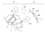
図1に示すように、ヘッドモーショントラッカ装置100は、頭部装着部1を備える。頭部装着部1は、ヘルメット形状を有しているが、ヘッドギア形状を有していてもよい。頭部装着部1は、航空機200を操縦する操縦者201の頭部201aに装着される。なお、操縦者201は、特許請求の範囲の「装着者」の一例である。 As shown in FIG. 1, the headmotion tracker device 100 includes a head-mountedunit 1. As shown in FIG. The head mountedpart 1 has a helmet shape, but may have a headgear shape. Head mountedunit 1 is mounted onhead 201 a ofoperator 201 who operatesaircraft 200 . Theoperator 201 is an example of the "wearer" in the claims.

また、頭部装着部1には、操縦者201の眼前に設けられるバイザー2が設けられる。バイザー2を介して、操縦者201が航空機200の操縦を補助する情報(たとえば機体姿勢および速度等のシンボル)が表示される。この表示を視認することにより、操縦者201は、航空機200の機体姿勢および速度等を調整することが可能となる。 Further, the head mountedunit 1 is provided with avisor 2 that is provided in front of theoperator 201 . Via thevisor 2, information (for example, symbols such as aircraft attitude and speed) that assists thepilot 201 in controlling theaircraft 200 is displayed. By visually recognizing this display, theoperator 201 can adjust the attitude, speed, etc. of theaircraft 200 .

図2に示すように、頭部装着部1には、カメラ3が設けられている。すなわち、カメラ3は、頭部装着部1と一体的に設けられている。ここで、本実施形態では、カメラ3は、頭部装着部1に複数(本実施形態では2つ)設けられている。2つのカメラ3は、頭部装着部1の前面において水平方向に並んで設けられている。なお、カメラ3の頭部装着部1における配置場所および並び方はこれに限られない。また、カメラ3のレンズの種類は限定されず、たとえば、広角レンズおよび魚眼レンズ等により構成されていてもよい。なお、カメラ3は、特許請求の範囲の「撮像部」の一例である。 As shown in FIG. 2, the head-mountedpart 1 is provided with acamera 3 . That is, thecamera 3 is provided integrally with the head-mountedportion 1 . Here, in this embodiment, a plurality of cameras 3 (two in this embodiment) are provided in the head-mountedunit 1 . The twocameras 3 are provided side by side in the horizontal direction on the front surface of the head-mountedpart 1 . Note that the location and arrangement of thecameras 3 on the head-mountedunit 1 are not limited to this. Moreover, the type of lens of thecamera 3 is not limited, and may be composed of, for example, a wide-angle lens, a fish-eye lens, or the like. Note that thecamera 3 is an example of the "imaging unit" in the scope of claims.

また、頭部装着部1には、近赤外光を照射する近赤外LED4が設けられている。近赤外LED4は、頭部装着部1に2つ設けられている。具体的には、水平方向において頭部装着部1の一方側に設けられている近赤外LED4は、頭部装着部1の一方側に設けられているカメラ3の撮像方向に近赤外光を照射する。また、水平方向において頭部装着部1の他方側に設けられている近赤外LED4は、頭部装着部1の他方側に設けられているカメラ3の撮像方向に近赤外光を照射する。頭部装着部1の一方側に設けられるカメラ3と近赤外LED4は隣接するように設けられ、頭部装着部1の他方側に設けられるカメラ3と近赤外LED4は隣接するように設けられている。なお、近赤外LED4および近赤外光は、それぞれ、特許請求の範囲の「光源部」および「非可視光」の一例である。 Further, the head mountedpart 1 is provided with a near-infrared LED 4 for emitting near-infrared light. Two near-infrared LEDs 4 are provided on the head-mountedpart 1 . Specifically, the near-infrared LED 4 provided on one side of the head-mountedunit 1 in the horizontal direction emits near-infrared light in the imaging direction of thecamera 3 provided on one side of the head-mountedunit 1. to irradiate. Further, the near-infrared LED 4 provided on the other side of the head-mountedunit 1 in the horizontal direction emits near-infrared light in the imaging direction of thecamera 3 provided on the other side of the head-mountedunit 1. . Thecamera 3 and the near-infrared LED 4 provided on one side of the head-mountedportion 1 are provided adjacent to each other, and thecamera 3 and the near-infrared LED 4 provided on the other side of the head-mountedportion 1 are provided adjacent to each other. It is The near-infrared LED 4 and the near-infrared light are examples of the "light source section" and the "invisible light" in the claims, respectively.

また、本実施形態では、カメラ3は、可視領域の波長から非可視領域の波長までの光を検出可能に構成されている。具体的には、カメラ3は、可視光および近赤外光の検出が可能に構成されている。 In addition, in this embodiment, thecamera 3 is configured to be capable of detecting light from wavelengths in the visible region to wavelengths in the non-visible region. Specifically, thecamera 3 is configured to detect visible light and near-infrared light.

また、ヘッドモーショントラッカ装置100は、近赤外LED4から照射される近赤外光を照射方向(カメラ3側)に反射する再帰性反射体5を備える。再帰性反射体5とは、光が入射された方向(照射方向)に光を反射させる反射体を意味する。再帰性反射体5は、航空機200のコックピット200a内の機体フレーム200b、キャノピー200c、および、ウィンドウ200d(図1参照)の各々に取り付けられている。なお、再帰性反射体5は、操縦者201の視認性を阻害しなければ、機体フレーム200b、キャノピー200c、および、ウィンドウ200d以外の場所にも取り付けられていてもよい。 The headmotion tracker device 100 also includes aretroreflector 5 that reflects near-infrared light emitted from the near-infrared LED 4 in the irradiation direction (camera 3 side). Theretroreflector 5 means a reflector that reflects light in the direction in which the light is incident (irradiation direction). Theretroreflector 5 is attached to each of thebody frame 200b, thecanopy 200c, and thewindow 200d (see FIG. 1) in thecockpit 200a of theaircraft 200. As shown in FIG. Note that theretroreflector 5 may be attached to a place other than thebody frame 200b, thecanopy 200c, and thewindow 200d as long as the visibility of theoperator 201 is not hindered.

また、再帰性反射体5は、透明な材質により形成されている。また、再帰性反射体5は、裏面に粘着テープ等が設けられたシート状の反射体であり、機体フレーム200b、キャノピー200c、および、ウィンドウ200dの各々に貼り付けられている。 Moreover, theretroreflector 5 is made of a transparent material. Theretroreflector 5 is a sheet-like reflector provided with an adhesive tape or the like on the back surface, and is attached to each of thebody frame 200b, thecanopy 200c, and thewindow 200d.

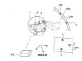
図3に示すように、頭部装着部1は、センサ6を含む。センサ6は、2つのカメラ3の各々に設けられている第1センサ6aを含む。第1センサ6aは、カメラ3の傾斜角度および向きを検出する。 As shown in FIG. 3, the head-mountedpart 1 includes asensor 6. As shown in FIG.Sensors 6 include afirst sensor 6 a provided on each of the twocameras 3 . Thefirst sensor 6 a detects the tilt angle and orientation of thecamera 3 .

また、センサ6は、第2センサ6bを含む。第2センサ6bは、頭部装着部1の加速度および角速度を検出する。Sensor 6 also includes asecond sensor 6b. Thesecond sensor 6b detects acceleration and angular velocity of the head-mountedpart 1 .

また、ヘッドモーショントラッカ装置100は、信号処理部7を備える。信号処理部7は、頭部装着部1に内蔵されている。信号処理部7は、制御部7aと、画像処理部7bと、センサデータ処理部7cと、記憶部7dと、比較部7eと、頭部角度位置算出部7fと、を含む。 The headmotion tracker device 100 also includes asignal processing section 7 . Thesignal processing section 7 is built in the head mountedsection 1 . Thesignal processing unit 7 includes acontrol unit 7a, animage processing unit 7b, a sensordata processing unit 7c, astorage unit 7d, acomparison unit 7e, and a head angleposition calculation unit 7f.

制御部7aは、カメラ3および近赤外LED4の各々に制御信号を送信するように構成されている。具体的には、制御部7aは、たとえば、カメラ3および近赤外LED4の各々のオンオフを制御する信号、および、近赤外LED4の発光強度等を制御する信号を送信する。 Thecontrol unit 7a is configured to transmit control signals to each of thecamera 3 and the near-infrared LEDs 4 . Specifically, thecontrol unit 7a transmits, for example, a signal for controlling ON/OFF of each of thecamera 3 and the near-infrared LED 4, and a signal for controlling the emission intensity of the near-infrared LED 4 and the like.

具体的には、制御部7aは、夜間等の周囲が暗い場合には、近赤外LED4をオンさせる制御信号を送る。また、昼間等の周囲が明るい場合にも近赤外LED4をオンさせてもよい。なお、近赤外LED4は、近赤外光の波長が850nm以上であるように構成されている。また、近赤外LED4は、夜間等の周囲が暗い場合で暗視機能を使用する用途では、930nm以上の波長の近赤外光を使用可能に構成されている。これにより、夜間等において、近赤外LED4からの近赤外光による暗視機能等への影響を低減することが可能である。 Specifically, thecontrol unit 7a sends a control signal to turn on the near-infrared LED 4 when the surroundings are dark such as at night. Also, the near-infrared LED 4 may be turned on even when the surroundings are bright, such as in the daytime. The near-infrared LED 4 is configured so that the near-infrared light has a wavelength of 850 nm or more. In addition, the near-infrared LED 4 is configured to be able to use near-infrared light with a wavelength of 930 nm or more in applications where the night vision function is used when the surroundings are dark such as at night. As a result, it is possible to reduce the influence of the near-infrared light from the near-infrared LEDs 4 on the night vision function and the like at night.

また、画像処理部7bは、2つのカメラ3の各々により撮像された画像に基づいて、画像処理を行うように構成されている。たとえば、画像処理部7bは、画像における光学歪補正および特徴点抽出等を行う。 Further, theimage processing section 7b is configured to perform image processing based on the images captured by the twocameras 3 respectively. For example, theimage processing unit 7b performs optical distortion correction, feature point extraction, and the like in the image.

また、センサデータ処理部7cは、第1センサ6aおよび第2センサ6bの各々の検出値(センサデータ)に基づいて、処理を行うように構成されている。 The sensordata processing unit 7c is configured to perform processing based on the detection values (sensor data) of each of thefirst sensor 6a and thesecond sensor 6b.

また、記憶部7dには、頭部装着部1の周囲の特徴点の情報を含む周囲環境情報が記憶されている。具体的には、周囲環境情報とは、周囲の特徴点の、所定の機体の基準座標における3次元座標情報である。また、周囲環境情報とは、所定の角度に傾いた頭部201aにおいて、所定の位置からカメラ3により画像(頭部201aの周囲の環境)を撮像した場合に撮像された画像において、上記特徴点が取得される位置の情報(画像上における位置の情報)に換算可能な情報を少なくとも含む。また、周囲環境情報は、上記特徴点が取得される位置の情報に加えて、上記特徴点の大きさの情報等を含んでいてもよい。また、カメラ3により取得された後述する前フレーム画像または画像中の特徴点は、記憶部7dに格納される。 Surrounding environment information including information on feature points around the head mountedunit 1 is stored in thestorage unit 7d. Specifically, the surrounding environment information is three-dimensional coordinate information of the surrounding feature points in the predetermined reference coordinates of the aircraft. Further, the surrounding environment information refers to an image (environment surrounding thehead 201a) captured by thecamera 3 from a predetermined position with thehead 201a tilted at a predetermined angle. contains at least information that can be converted to information on the position where is acquired (information on the position on the image). Further, the ambient environment information may include information on the size of the feature point, etc., in addition to the information on the position where the feature point is acquired. Further, a previous frame image, which will be described later, or a feature point in the image acquired by thecamera 3 is stored in thestorage unit 7d.

ここで、本実施形態では、周囲環境情報は、操縦者201の周囲に設けられた装備品の少なくとも位置情報を含む。たとえば、周囲環境情報は、再帰性反射体5の位置情報、機体フレーム200bの位置情報、キャノピー200cの位置情報、および、ウィンドウ200dの位置情報等を含む。なお、機体フレーム200b、キャノピー200c、ウィンドウ200d、および、再帰性反射体5の各々は、上記装備品の一例である。なお、周囲環境情報は、コックピット200aの壁面、天井面、および、角部等の位置情報等を含んでいてもよい。 Here, in the present embodiment, the surrounding environment information includes at least position information of equipment provided around theoperator 201 . For example, the ambient environment information includes positional information of theretroreflector 5, positional information of thebody frame 200b, positional information of thecanopy 200c, and positional information of thewindow 200d. Note that each of thebody frame 200b, thecanopy 200c, thewindow 200d, and theretroreflector 5 is an example of the equipment. The ambient environment information may include positional information of the walls, ceiling, and corners of thecockpit 200a.

また、比較部7eは、現在のフレームにおいてカメラ3により撮像された画像(以下、現フレーム画像)と、現在のフレームよりも前のフレームにおいてカメラ3により撮像された画像(以下、前フレーム画像)とを比較するように構成されている。また、比較部7eは、現フレーム画像と、記憶部7dに記憶された周囲環境情報とを比較するように構成されている。なお、カメラ3のフレームレートは、たとえば60Hz以上である。 Thecomparison unit 7e compares an image captured by thecamera 3 in the current frame (hereinafter referred to as the current frame image) and an image captured by thecamera 3 in the frame before the current frame (hereinafter referred to as the previous frame image). is configured to compare with Also, thecomparison unit 7e is configured to compare the current frame image with the ambient environment information stored in thestorage unit 7d. Note that the frame rate of thecamera 3 is, for example, 60 Hz or higher.

また、頭部角度位置算出部7fは、比較部7eによる比較結果に基づいて、頭部201a(頭部装着部1)の角度および位置を算出するように構成されている。頭部角度位置算出部7fにより算出された頭部201aの角度および位置の情報は、HMD回路(図示せず)を含む装置(図示せず)に送信される。上記HMD回路は、送信された頭部201aの角度および位置の情報に基づいて、バイザー2を介して操縦者201に表示する画像を作成する。なお、上記HMD回路を含む装置は、頭部装着部1の外部および内部のいずれに設けられていてもよい。 The headangle position calculator 7f is configured to calculate the angle and position of thehead 201a (head mounted part 1) based on the comparison result of thecomparator 7e. Information on the angle and position of thehead 201a calculated by the headangle position calculator 7f is transmitted to a device (not shown) including an HMD circuit (not shown). The HMD circuit creates an image to be displayed to theoperator 201 via thevisor 2 based on the transmitted information on the angle and position of thehead 201a. Note that the device including the HMD circuit may be provided either inside or outside the head mountedunit 1 .

ここで、本実施形態では、信号処理部7は、現フレーム画像と、周囲環境情報および前フレーム画像のうちの少なくとも一方とに基づいて、現在のフレームにおける頭部201aの位置および角度を算出するように構成されている。具体的には、信号処理部7は、現フレーム画像と、周囲環境情報および前フレーム画像のうちの少なくとも一方とを比較することにより、現在のフレームにおける頭部201aの位置および角度を算出するように構成されている。なお、信号処理部7は、上記比較において、周囲環境情報および前フレーム画像のうちのいずれを使用するかを切り替えるように構成されていてもよいし、いずれか一方のみを使用するように構成されていてもよい。 Here, in this embodiment, thesignal processing unit 7 calculates the position and angle of thehead 201a in the current frame based on the current frame image and at least one of the surrounding environment information and the previous frame image. is configured as Specifically, thesignal processing unit 7 calculates the position and angle of thehead 201a in the current frame by comparing the current frame image with at least one of the surrounding environment information and the previous frame image. is configured to In the above comparison, thesignal processing unit 7 may be configured to switch between the surrounding environment information and the previous frame image to be used, or may be configured to use only one of them. may be

(現フレーム画像と前フレーム画像との比較による算出)
図4を参照して、現フレーム画像と前フレーム画像とを比較することにより、現在のフレームにおける頭部201aの位置および角度を算出する場合の信号処理部7の制御について説明する。
(Calculation by comparison between current frame image and previous frame image)
Referring to FIG. 4, the control of thesignal processing unit 7 when calculating the position and angle of thehead 201a in the current frame by comparing the current frame image and the previous frame image will be described.

図4に示すように、ステップS1において、信号処理部7(頭部角度位置算出部7f)は、初期のフレームの画像(以下、初期フレーム画像)と周囲環境情報とに基づいて、初期のフレームにおける頭部201aの位置および角度の基準値を算出するように構成されている。具体的には、信号処理部7(頭部角度位置算出部7f)は、初期フレーム画像において取得された所定の特徴点(たとえば再帰性反射体5)と、所定の角度で所定の位置に設けられている頭部201aに対応する周囲環境情報に含まれる上記所定の特徴点の位置情報等とを比較する。この比較結果により算出される上記所定の特徴点の位置および大きさ等の変化量に基づいて、上記周囲環境情報に対応する上記所定の角度および上記所定の位置と、初期のフレームにおける頭部201aの位置および角度との差異が検出される。その結果、初期のフレームにおける頭部201aの位置および角度(基準値)が算出される。 As shown in FIG. 4, in step S1, the signal processing unit 7 (head angleposition calculation unit 7f) calculates the initial frame image based on the initial frame image (hereinafter referred to as the initial frame image) and the surrounding environment information. is configured to calculate the reference values of the position and angle of thehead 201a. Specifically, the signal processing unit 7 (head angleposition calculation unit 7f) uses a predetermined feature point (for example, the retroreflector 5) acquired in the initial frame image and a predetermined position at a predetermined angle. It compares with the positional information and the like of the predetermined feature point included in the ambient environment information corresponding to thehead 201a. Based on the amount of change in the position and size of the predetermined feature point calculated from the comparison result, the predetermined angle and the predetermined position corresponding to the ambient environment information and thehead 201a in the initial frame are calculated. are detected. As a result, the position and angle (reference value) of thehead 201a in the initial frame are calculated.

次に、ステップS2において、本実施形態では、信号処理部7(頭部角度位置算出部7f)は、上記基準値、および、前フレーム画像と現フレーム画像との比較結果に基づいて、現在のフレームの頭部201aの位置および角度を算出するように構成されている。 Next, in step S2, in this embodiment, the signal processing unit 7 (head angleposition calculation unit 7f) calculates the current value based on the reference value and the result of comparison between the previous frame image and the current frame image It is configured to calculate the position and angle of thehead 201a of the frame.

具体的には、信号処理部7(頭部角度位置算出部7f)は、上記基準値、および、初期フレーム画像と初期のフレームの次のフレーム(以下、N1フレーム)における画像との比較結果に基づいて、N1フレームにおける頭部201aの位置および角度を算出する。具体的な算出方法としては、上記ステップS1で説明した方法と同様である。すなわち、初期フレーム画像において取得された所定の特徴点(たとえば再帰性反射体5)と、N1フレーム画像において取得された上記所定の特徴点とが比較される。この比較結果により算出される上記所定の特徴点の位置および大きさ等の変化量に基づいて、初期フレームにおける頭部201aの位置および角度と、N1フレームにおける頭部201aの位置および角度との差異(すなわち頭部201aの位置および角度の各々の変化量)が検出される。その結果、N1フレームにおける頭部201aの位置および角度が算出される。 Specifically, the signal processing unit 7 (head angleposition calculation unit 7f) compares the reference value and the result of comparison between the initial frame image and the image in the next frame of the initial frame (hereinafter referred to as N1 frame). Based on this, the position and angle of thehead 201a in the N1 frame are calculated. A specific calculation method is the same as the method described in step S1 above. That is, a predetermined feature point (for example, the retroreflector 5) acquired in the initial frame image is compared with the predetermined feature point acquired in the N1 frame image. The difference between the position and angle of thehead 201a in the initial frame and the position and angle of thehead 201a in the N1 frame, based on the amount of change in the position and size of the predetermined feature point calculated from the comparison result. (that is, the amount of change in each of the position and angle of thehead 201a) is detected. As a result, the position and angle of thehead 201a in the N1 frame are calculated.

次に、N1フレームにおける頭部201aの位置および角度を基準値として、N1フレームの画像とN1フレームの次のフレーム(以下、N2フレーム)の画像との比較結果に基づいて、N2フレームにおける頭部201aの位置および角度が算出される。このように、フレーム間の画像の比較が各フレームにおいて行われることによって、各フレームにおける頭部201aの位置および角度が算出される。これにより、現在のフレームの頭部201aの位置および角度が算出される。 Next, using the position and angle of thehead 201a in the N1 frame as reference values, the head in the N2 frame is calculated based on the result of comparison between the image of the N1 frame and the image of the frame next to the N1 frame (hereinafter referred to as the N2 frame). The position and angle of 201a are calculated. Thus, the position and angle of thehead 201a in each frame are calculated by comparing the images between frames in each frame. Thereby, the position and angle of thehead 201a in the current frame are calculated.

(現フレーム画像と周囲環境情報との比較による算出)
次に、図5を参照して、現フレーム画像と周囲環境情報とを比較することにより、現在のフレームにおける頭部201aの位置および角度を算出する場合の信号処理部7の制御について説明する。
(Calculation by comparison of current frame image and ambient environment information)
Next, referring to FIG. 5, the control of thesignal processing unit 7 when calculating the position and angle of thehead 201a in the current frame by comparing the current frame image and the surrounding environment information will be described.

まず、ステップS11において、信号処理部7(頭部角度位置算出部7f)は、初期のフレームの画像(以下、初期フレーム画像)と周囲環境情報とに基づいて、初期のフレームにおける頭部201aの位置および角度の基準値を算出するように構成されている。この制御は、上記ステップS1と同じであるので、詳細な説明は省略する。 First, in step S11, the signal processing unit 7 (head angleposition calculation unit 7f) calculates the position of thehead 201a in the initial frame based on the initial frame image (hereinafter referred to as the initial frame image) and the surrounding environment information. It is configured to calculate position and angle reference values. Since this control is the same as that of step S1, detailed description thereof will be omitted.

次に、ステップS12において、信号処理部7(頭部角度位置算出部7f)は、前フレームにおける頭部201aの位置および角度と、センサ6の検出値とに基づいて、現在のフレームの頭部201aの概略的な位置および概略的な角度を算出する。この際、センサ6の検出値として、第1センサ6aにより検出されたカメラ3の傾斜角度および向きのデータと、第2センサ6bにより検出された頭部装着部1の加速度および角速度のデータとが用いられる。 Next, in step S12, the signal processing unit 7 (head angleposition calculation unit 7f) calculates the position and angle of thehead 201a in the previous frame and the detection value of thesensor 6, and calculates the position and angle of thehead 201a in the current frame. Compute the approximate position and approximate angle of 201a. At this time, as the detection values of thesensor 6, the tilt angle and orientation data of thecamera 3 detected by thefirst sensor 6a and the acceleration and angular velocity data of the head-mountedpart 1 detected by thesecond sensor 6b are combined. Used.

次に、ステップS13において、本実施形態では、信号処理部7は、現フレーム画像と、頭部201aの上記概略的な位置および上記概略的な角度に対応する周囲環境情報とを比較することにより、現在のフレームの頭部201aの位置および角度を算出するように構成されている。具体的には、信号処理部7は、記憶部7d(図3参照)に記憶されている周囲環境情報のうち、頭部201aの上記概略的な位置および上記概略的な角度に対応する周囲環境情報を取得する(読み出す)とともに、記憶部7dから取得された(読み出された)周囲環境情報と、現フレーム画像との比較を行う。 Next, in step S13, in this embodiment, thesignal processing unit 7 compares the current frame image with the ambient environment information corresponding to the general position and the general angle of the head 201a. , is configured to calculate the position and angle of thehead 201a in the current frame. Specifically, thesignal processing unit 7 selects the surrounding environment corresponding to the general position and the general angle of thehead 201a from among the surrounding environment information stored in thestorage unit 7d (see FIG. 3). Information is acquired (read out), and the surrounding environment information acquired (read out) from thestorage unit 7d is compared with the current frame image.

詳細には、信号処理部7(頭部角度位置算出部7f)は、現フレーム画像において取得された所定の特徴点(たとえば再帰性反射体5)と、上記概略的な位置および上記概略的な角度に対応する周囲環境情報に含まれる上記所定の特徴点の位置情報等とを比較する。この比較結果により算出される上記所定の特徴点の位置等の差異に基づいて、上記周囲環境情報と、現在のフレームにおける頭部201aの位置および角度との差異が検出される。その結果、現在のフレームにおける頭部201aの位置および角度が算出される。なお、ステップS12において用いられた前フレームにおける頭部201aの位置および角度は、ステップS11において算出された基準値に基づいて、ステップS13の制御がフレーム毎に繰り返し行われることにより算出されている。 Specifically, the signal processing unit 7 (head angleposition calculation unit 7f) calculates a predetermined feature point (for example, the retroreflector 5) acquired in the current frame image, the above approximate position and the above approximate It compares with the positional information of the predetermined feature point, etc. included in the ambient environment information corresponding to the angle. A difference between the surrounding environment information and the position and angle of thehead 201a in the current frame is detected based on the difference in the position of the predetermined characteristic point calculated from the comparison result. As a result, the position and angle ofhead 201a in the current frame are calculated. The position and angle of thehead 201a in the previous frame used in step S12 are calculated by repeating the control in step S13 for each frame based on the reference values calculated in step S11.

また、ヘッドモーショントラッカ装置100(信号処理部7)では、現フレーム画像と前フレーム画像との比較を行う制御と、現フレーム画像と周囲環境情報との比較を行う制御との切り替え可能に構成されていてもよい。たとえば、通常時は現フレーム画像と周囲環境情報との比較が行われる一方、第1センサ6aまたは第2センサ6bの情報から周囲環境情報の取得ができなかった場合などに、現フレーム画像と前フレーム画像との比較を行う制御に切り替えられるように構成されていてもよい。また、通常時は現フレーム画像と前フレーム画像との比較が行われる一方、カメラ3により前フレーム画像が撮像されなかった場合などに、現フレーム画像と周囲環境情報との比較を行う制御に切り替えられるように構成されていてもよい。なお、途中で制御が切り替えられる場合は、上記ステップS1(図4参照)およびステップS11(図5参照)の制御は行わなくてもよい。また、現フレーム画像と前フレーム画像との比較を行う制御と、現フレーム画像と周囲環境情報との比較を行う制御のうちのいずれか一方の制御のみが行われるように構成されていてもよい。 Further, the head motion tracker device 100 (signal processing unit 7) is configured to be switchable between control for comparing the current frame image and the previous frame image and control for comparing the current frame image and surrounding environment information. may be For example, the current frame image and the surrounding environment information are normally compared with each other. It may be configured to switch to control for comparison with a frame image. Also, while the current frame image and the previous frame image are normally compared, when the previous frame image is not captured by thecamera 3, the control is switched to compare the current frame image and the surrounding environment information. It may be configured to be Note that if the control is switched in the middle, the control in steps S1 (see FIG. 4) and step S11 (see FIG. 5) need not be performed. Alternatively, only one of the control of comparing the current frame image and the previous frame image and the control of comparing the current frame image and the surrounding environment information may be performed. .

また、本実施形態では、信号処理部7は、現在のフレームの頭部201aの位置および角度の算出が所定の時間(たとえば1フレーム)内に行われなかった場合に、センサ6の検出値に基づいて補間を行うように構成されている。信号処理部7は、上記補間を行うことにより、前フレームにおける頭部201aの位置および角度から、現在のフレームの頭部201aの位置および角度を算出するように構成されている。具体的には、信号処理部7は、現在のフレームの頭部201aの位置および角度の算出が所定の時間内に行われなかった場合に、前フレームにおける頭部201aの位置および角度と、第2センサ6bにより検出された頭部装着部1の加速度および角速度とに基づいて、現在のフレームの頭部201aの位置および角度を補間により算出する。 In addition, in the present embodiment, thesignal processing unit 7 changes the detection value of thesensor 6 to the value detected by thesensor 6 when the calculation of the position and angle of thehead 201a in the current frame is not performed within a predetermined time (for example, one frame). It is configured to interpolate based on Thesignal processing unit 7 is configured to calculate the position and angle of thehead 201a in the current frame from the position and angle of thehead 201a in the previous frame by performing the above interpolation. Specifically, when the position and angle of thehead 201a in the current frame are not calculated within a predetermined period of time, thesignal processing unit 7 calculates the position and angle of thehead 201a in the previous frame and the 2 Based on the acceleration and angular velocity of the head-mountedunit 1 detected by thesensor 6b, the position and angle of thehead 201a in the current frame are calculated by interpolation.

この場合、信号処理部7に設けられる図示しないタイマ等により、上記算出が所定の時間内に行われたか否かを検知可能に構成されていてもよい。なお、現在のフレームの頭部201aの位置および角度の算出が所定の時間内に行われない場合とは、ノイズ等に起因してカメラ3により適切な画像が撮像されなかったことに起因して、現フレーム画像において前フレーム画像(周囲環境情報)等と位置の比較が行われる所定の特徴点(たとえば再帰性反射体5)の検出(発見)に時間を要した場合等が考えられる。 In this case, a timer or the like (not shown) provided in thesignal processing section 7 may detect whether or not the above calculation has been performed within a predetermined period of time. The case where the calculation of the position and angle of thehead 201a in the current frame is not performed within a predetermined time means that an appropriate image was not captured by thecamera 3 due to noise or the like. Also, it may take time to detect (discover) a predetermined feature point (for example, the retroreflector 5) whose position is compared with the previous frame image (surrounding environment information) in the current frame image.

また、図6を参照して、現在のフレームの頭部201aの位置および角度に対応する周囲環境情報が記憶部7dに記憶されていない場合の信号処理部7の制御ついて説明する。 Further, referring to FIG. 6, the control of thesignal processing section 7 when the ambient environment information corresponding to the position and angle of thehead 201a in the current frame is not stored in thestorage section 7d will be described.

図6に示すように、現在のフレームよりも前のフレームにおいて、周囲環境情報が記憶部7dに記憶されている領域Aの方向に頭部201aが向いた状態で画像300が取得されたとする。また、現在のフレームにおいて、周囲環境情報が記憶部7dに記憶されていない領域Bの方向に頭部201aが向いた状態で画像301が取得されているとする。 As shown in FIG. 6, it is assumed that animage 300 is acquired in a frame prior to the current frame with thehead 201a facing toward the area A whose ambient environment information is stored in thestorage unit 7d. It is also assumed that theimage 301 is acquired in the current frame with thehead 201a directed toward the area B for which the ambient environment information is not stored in thestorage unit 7d.

この場合、本実施形態では、周囲環境情報が記憶部7dに記憶されている頭部201aの位置および角度(領域Aの方向に対する頭部201aの位置および角度)と、周囲環境情報が記憶部7dに記憶されていない頭部201aの位置(領域Bの方向に対する頭部201aの位置)からの頭部201aの移動量Lと、現フレーム画像(この場合、画像301)とに基づいて、現在のフレームの頭部201aの位置および角度を算出するように構成されている。 In this case, in this embodiment, the position and angle of thehead 201a (the position and angle of thehead 201a with respect to the direction of the area A) whose ambient environment information is stored in thestorage unit 7d and the ambient environment information are stored in thestorage unit 7d. Based on the movement amount L of thehead 201a from the position of thehead 201a not stored in the current It is configured to calculate the position and angle of thehead 201a of the frame.

具体的には、信号処理部7は、画像300および領域Aの方向に対応する周囲環境情報から領域Aの方向に対する頭部201aの位置および角度を算出するように構成されている。また、信号処理部7は、前フレーム画像(画像300)および現フレーム画像(画像301)の各々において同一の所定の特徴点(たとえば再帰性反射体5)が取得されている場合に、上記所定の特徴点の位置、方向および大きさ等の変化量に基づいて、フレーム間における頭部201aの位置の移動量L(および頭部201aの角度の変化量)を算出する。そして、信号処理部7は、領域Aの方向に対する頭部201aの位置および角度と、頭部201aの位置の移動量L(および頭部201aの角度の変化量)とに基づいて、領域Bの方向に対する頭部201aの位置および角度を算出する。 Specifically, thesignal processing unit 7 is configured to calculate the position and angle of thehead 201a with respect to the direction of the area A from theimage 300 and the ambient environment information corresponding to the direction of the area A. FIG. Further, when the same predetermined feature point (for example, the retroreflector 5) is acquired in each of the previous frame image (image 300) and the current frame image (image 301), thesignal processing unit 7 detects the predetermined The amount of movement L of the position of thehead 201a (and the amount of change in the angle of thehead 201a) between the frames is calculated based on the amount of change in the position, direction, size, etc. of the feature point. Then, thesignal processing unit 7, based on the position and angle of thehead 201a with respect to the direction of the region A, and the amount of movement L of the position of thehead 201a (and the amount of change in the angle of thehead 201a), Calculate the position and angle of thehead 201a with respect to the direction.

さらに、信号処理部7は、領域Aの方向に対する頭部201aの位置および角度と、頭部201aの位置の移動量L(および頭部201aの角度の変化量)と、現フレーム画像(画像301)とに基づいて、現在のフレームの頭部201aの位置および角度に対応する周囲環境情報の作成および記憶部7dへの登録を行う。具体的には、領域Bに対応する画像301から特徴点が抽出されるとともに、抽出された領域Bに対応する特徴点と、領域Bの方向に対する頭部201aの位置および角度とに基づいて、領域Bに対応する周囲環境情報が新たに作成されるとともに記憶部7dに登録(追加)される。これにより、周囲環境情報がない領域の方向でも、頭部201aの位置および角度算出が可能になるとともに、この処理が繰り返し行われることにより、周囲環境情報をさらに更新(増加)することが可能である。その結果、上記処理が行われる度に、頭部201aの位置および角度の算出の精度を向上させることが可能である。 Further, thesignal processing unit 7 processes the position and angle of thehead 201a with respect to the direction of the area A, the amount of movement L of the position of thehead 201a (and the amount of change in the angle of thehead 201a), and the current frame image (image 301 ), the ambient environment information corresponding to the position and angle of thehead 201a in the current frame is created and registered in thestorage unit 7d. Specifically, feature points are extracted from theimage 301 corresponding to the region B, and based on the extracted feature points corresponding to the region B and the position and angle of thehead 201a with respect to the direction of the region B, Surrounding environment information corresponding to the area B is newly created and registered (added) in thestorage unit 7d. As a result, it is possible to calculate the position and angle of thehead 201a even in the direction of an area where there is no surrounding environment information, and by repeating this processing, it is possible to further update (increase) the surrounding environment information. be. As a result, it is possible to improve the accuracy of calculating the position and angle of thehead 201a each time the above processing is performed.

また、現フレーム画像(画像301)において前フレーム画像(画像300)と同一の所定の特徴点(たとえば再帰性反射体5)が取得されない場合には、領域Aと領域Bとの中間領域(領域Aと領域Bとに跨る領域)に対する頭部201aの位置および角度に基づいて、現在のフレームの頭部201aの位置および角度を算出してもよい。なお、現在のフレームまでに、中間領域の方向に頭部201aが向いた状態で画像302が取得されているとする。 Further, when the same predetermined feature point (for example, the retroreflector 5) as in the previous frame image (image 300) is not acquired in the current frame image (image 301), an intermediate region (region The position and angle of thehead 201a in the current frame may be calculated based on the position and angle of thehead 201a with respect to the area spanning A and B). Assume that theimage 302 has been acquired with thehead 201a directed toward the intermediate area by the current frame.

この場合、中間領域に対応する画像302のうちの領域A側の画像と、領域A側に対応する周囲環境情報とに基づいて、中間領域に対する頭部201aの位置および角度が算出される。また、中間領域に対応する画像302のうちの領域B側の画像から特徴点(たとえば再帰性反射体5)が抽出される。抽出された領域B側の特徴点と、中間領域に対する頭部201aの位置および角度とに基づいて、中間領域に対応する周囲環境情報が作成されるとともに登録される。 In this case, the position and angle of thehead 201a with respect to the intermediate area are calculated based on the image of the area A side in theimage 302 corresponding to the intermediate area and the ambient environment information corresponding to the area A side. Further, a feature point (for example, the retroreflector 5) is extracted from the image on the area B side of theimage 302 corresponding to the intermediate area. Based on the extracted feature points on the region B side and the position and angle of thehead 201a with respect to the intermediate region, ambient environment information corresponding to the intermediate region is created and registered.

そして、信号処理部7は、中間領域に対応する画像302および現フレーム画像(画像301)の各々における同一の所定の特徴点の位置、方向および大きさ等の変化量に基づいて算出される頭部201aの位置の移動量(頭部201aの角度の変化量)と、中間領域に対する頭部201aの位置および角度とに基づいて、領域Bの方向に対する頭部201aの位置および角度を算出する。その後、上記と同様に、領域Bに対応する周囲環境情報が新たに作成されるとともに記憶部7dに登録(追加)される。 Then, thesignal processing unit 7 calculates the head position calculated based on the amount of change in the position, direction, size, etc., of the same predetermined feature point in each of theimage 302 corresponding to the intermediate region and the current frame image (image 301). The position and angle of thehead 201a with respect to the direction of the area B are calculated based on the amount of movement of the position of thepart 201a (the amount of change in the angle of thehead 201a) and the position and angle of thehead 201a with respect to the intermediate area. Thereafter, in the same manner as described above, the ambient environment information corresponding to the area B is newly created and registered (added) in thestorage unit 7d.

また、現フレーム画像(画像301)において前フレーム画像(画像300)と同一の所定の特徴点(たとえば再帰性反射体5)が取得されない場合で、かつ、中間領域において画像が取得されない場合には、領域Aの方向に対応する頭部201aの位置および角度と、第2センサ6bにより検出された加速度および角速度とにより、領域Bに対応する頭部201aの位置および角度を算出してもよい。 Further, when the same predetermined feature point (for example, retroreflector 5) as in the previous frame image (image 300) is not obtained in the current frame image (image 301), and when the image is not obtained in the intermediate area, , the position and angle of thehead 201a corresponding to the direction of the region A, and the acceleration and angular velocity detected by thesecond sensor 6b, the position and angle of thehead 201a corresponding to the region B may be calculated.

また、本実施形態では、信号処理部7は、周囲環境情報のアライメント情報を予め取得し、取得したアライメント情報を反映した周囲環境情報を用いて頭部201aの位置および角度を算出するように構成されている。 Further, in the present embodiment, thesignal processing unit 7 is configured to acquire the alignment information of the surrounding environment information in advance, and to calculate the position and angle of thehead 201a using the surrounding environment information reflecting the acquired alignment information. It is

具体的には、図7に示すように、アライメント装置202により、航空機200の姿勢情報および方位情報に基づいたアライメントに関するデータ(以下、アライメントデータ)を取得しておく。アライメントデータとは、たとえば、航空機200が飛行していない状態において、航空機200の機体の基準座標に対する航空機200の傾斜角度等の情報を含む。すなわち、機体静止状態での所定の機体の基準座標に対する周囲環境情報の位置情報を予め取得するアライメントが行われる。 Specifically, as shown in FIG. 7 ,alignment device 202 acquires alignment data (hereinafter referred to as alignment data) based on attitude information and azimuth information ofaircraft 200 . Alignment data includes information such as the angle of inclination ofaircraft 200 with respect to the reference coordinates of the fuselage ofaircraft 200 whenaircraft 200 is not in flight, for example. That is, alignment is performed to previously acquire the position information of the ambient environment information with respect to the predetermined reference coordinates of the aircraft in the static state of the aircraft.

アライメント装置202は、アライメント時のみ使用され、アライメント装置202には、航空機200のインターフェースから機体姿勢および方位情報が入力される。なお、ヘッドモーショントラッカ装置100自体が航空機200のインターフェースに直接的に接続されていてもよい。 Thealignment device 202 is used only during alignment, and the aircraft attitude and heading information is input to thealignment device 202 from the interface of theaircraft 200 . Note that the headmotion tracker device 100 itself may be directly connected to the interface of theaircraft 200 .

また、ヘッドモーショントラッカ装置100は、無線(たとえばWifi)または有線(たとえばイーサネット(登録商標))を介して、アライメント装置202からアライメントデータを取得している。 Further, the headmotion tracker device 100 acquires alignment data from thealignment device 202 via wireless (for example, Wifi) or wired (for example, Ethernet (registered trademark)).

また、信号処理部7では、アライメント装置202から取得したアライメントデータ(機体姿勢および方位情報)および現フレーム画像の特徴点と、第1センサ6aにより検出されたカメラ3の傾斜角度および向きのデータとの対応付けが行われる。そして、信号処理部7(たとえば記憶部7d)に、現フレーム画像の特徴点の、所定の機体の基準座標に対する3次元座標および形状等の情報テーブル(上記アライメント情報の一例)が保持される。信号処理部7は、上記テーブルを参照することにより、所定の機体の基準座標に対する現在のフレームにおける頭部201aの位置および角度を算出する。具体的には、上記ステップS1(図4参照)および上記ステップS11(図5参照)の各々において上記テーブルの情報が考慮された状態で、頭部201aの位置および角度の算出が行われる。言い換えれば、現在のフレームにおける頭部201aの位置および角度は、上記テーブルの情報により補正された上記基準値に基づいて算出される。 In thesignal processing unit 7, the alignment data (aircraft attitude and direction information) obtained from thealignment device 202, the feature points of the current frame image, and the tilt angle and orientation data of thecamera 3 detected by thefirst sensor 6a. are mapped. Then, the signal processing unit 7 (for example, thestorage unit 7d) holds an information table (an example of the alignment information) of the three-dimensional coordinates of the feature points of the current frame image with respect to the predetermined reference coordinates of the aircraft, the shape, and the like. Thesignal processing unit 7 calculates the position and angle of thehead 201a in the current frame with respect to the predetermined reference coordinates of the aircraft by referring to the table. Specifically, the position and angle of thehead 201a are calculated in a state in which the information in the table is considered in each of steps S1 (see FIG. 4) and S11 (see FIG. 5). In other words, the position and angle of thehead 201a in the current frame are calculated based on the reference values corrected by the information in the table.

なお、ヘッドモーショントラッカ100の使用時には、現在のフレームにおける頭部201aの位置および角度を算出において、航空機200が飛行時の機体姿勢、方向、加速度、および、角速度等の情報が参照(図3参照)される。 When thehead motion tracker 100 is used, the position and angle of thehead 201a in the current frame are calculated by referring to information such as the aircraft posture, direction, acceleration, and angular velocity during flight of the aircraft 200 (see FIG. 3). ) is done.

(本実施形態の効果)
本実施形態では、以下のような効果を得ることができる。
(Effect of this embodiment)
The following effects can be obtained in this embodiment.

本実施形態では、上記のように、ヘッドモーショントラッカ装置100は、操縦者201の頭部201aに装着され、画像を撮像するカメラ3を含む頭部装着部1を備える。また、ヘッドモーショントラッカ装置100は、現在のフレームにおいてカメラ3により撮像された現フレーム画像と、頭部装着部1の周囲の特徴点の情報を含む周囲環境情報、および、現在のフレームよりも前の前フレームにおいてカメラ3により撮像された前フレーム画像のうちの少なくとも一方とに基づいて、現在のフレームにおける頭部201aの位置および角度を算出する信号処理部7を備える。これにより、頭部装着部1以外の場所にカメラ3が設けられる場合と異なり、頭部201aの周囲の状態(たとえば、コックピット200aの形状、大きさ、コックピット200a内の装備等の位置)によって、カメラ3の取り付け位置およびカメラ3の取り付け方法を検討する必要がない。なお、カメラ3が頭部装着部1に含まれている場合でも、カメラ3により撮像された現フレーム画像と、周囲環境情報および前フレーム画像のうちの少なくとも一方とに基づいて、現在のフレームにおける頭部201aの位置および角度を算出することができる。その結果、カメラ3の取り付けを容易化しながら、頭部201aの動きを検出することができる。 In this embodiment, as described above, the headmotion tracker device 100 includes the head-mountedunit 1 that is mounted on thehead 201a of theoperator 201 and includes thecamera 3 that captures images. The headmotion tracker device 100 also includes the current frame image captured by thecamera 3 in the current frame, ambient environment information including information on feature points around the head-mountedunit 1, and an image before the current frame. Asignal processing unit 7 for calculating the position and angle of thehead 201a in the current frame based on at least one of the previous frame images captured by thecamera 3 in the previous frame. As a result, unlike the case where thecamera 3 is provided in a place other than the head-mountedpart 1, depending on the surrounding conditions of thehead 201a (for example, the shape and size of thecockpit 200a, the positions of the equipment in thecockpit 200a), It is not necessary to consider the mounting position of thecamera 3 and the mounting method of thecamera 3. Note that even when thecamera 3 is included in the head mountedunit 1, based on the current frame image captured by thecamera 3 and at least one of the surrounding environment information and the previous frame image, The position and angle ofhead 201a can be calculated. As a result, the movement of thehead 201a can be detected while thecamera 3 is easily attached.

また、本実施形態では、上記のように、信号処理部7を、現フレーム画像と、周囲環境情報および前フレーム画像のうちの少なくとも一方とを比較することにより、現在のフレームにおける頭部201aの位置および角度を算出するように構成する。これにより、周囲環境情報および前フレーム画像を基準に、現在のフレームにおける頭部201aの位置および角度を算出することができる。その結果、現在のフレームにおける頭部201aの位置および角度を容易に算出することができる。 Further, in the present embodiment, as described above, thesignal processing unit 7 compares the current frame image with at least one of the ambient environment information and the previous frame image to determine the position of thehead 201a in the current frame. Configure to calculate position and angle. As a result, the position and angle of thehead 201a in the current frame can be calculated based on the ambient environment information and the previous frame image. As a result, the position and angle ofhead 201a in the current frame can be easily calculated.

また、本実施形態では、上記のように、信号処理部7を、周囲環境情報としての、操縦者201の周囲に設けられた装備品(再帰性反射体5、機体フレーム200b、キャノピー200c、および、ウィンドウ200d)の少なくとも位置情報に基づいて、現在のフレームの頭部201aの位置および角度を算出するように構成する。ここで、上記装備品の位置情報は、信号処理部7による制御中に変化しない情報である。したがって、上記装備品の位置情報に基づいて、現在のフレームの頭部201aの位置および角度を算出することによって、制御中に変化する情報に基づいて制御を行う場合に比べて、信号処理部7の制御を簡易化することができる。 In addition, in the present embodiment, as described above, thesignal processing unit 7 is used as surrounding environment information for equipment provided around the operator 201 (retroreflector 5,body frame 200b,canopy 200c, and ,window 200d), the position and angle of thehead 201a in the current frame are calculated. Here, the position information of the equipment is information that does not change during control by thesignal processing unit 7 . Therefore, by calculating the position and angle of thehead 201a in the current frame based on the positional information of the accessory, thesignal processing unit 7 can be operated more efficiently than when performing control based on information that changes during control. can be simplified.

また、本実施形態では、上記のように、上記装備品としての、近赤外LED4から照射される近赤外光を照射方向に反射する再帰性反射体5を備えるように、ヘッドモーショントラッカ装置100を構成する。ここで、再帰性反射体5は、照射方向に近赤外光を反射するので、暗所においてもカメラ3により容易に視認される。また、再帰性反射体5を設けることによって、再帰性反射体5以外の部品がカメラ3により視認され難くなるので、カメラ3により取得可能な情報量が低減される。その結果、再帰性反射体5を設けることにより、暗所においても現在のフレームの頭部201aの位置および角度を算出することができるとともに、カメラ3により取得可能な情報量の低減に起因して上記算出における信号処理部7の処理の負荷を低減することができる。 Further, in the present embodiment, as described above, the head motion tracker device is provided with theretroreflector 5 that reflects the near-infrared light emitted from the near-infrared LED 4 in the irradiation direction. 100. Here, since theretroreflector 5 reflects the near-infrared light in the irradiation direction, it can be easily recognized by thecamera 3 even in a dark place. Also, by providing theretroreflector 5, it becomes difficult for thecamera 3 to visually recognize parts other than theretroreflector 5, so the amount of information that can be acquired by thecamera 3 is reduced. As a result, by providing theretroreflector 5, it is possible to calculate the position and angle of thehead 201a in the current frame even in a dark place. It is possible to reduce the processing load of thesignal processing unit 7 in the above calculation.

また、本実施形態では、上記のように、再帰性反射体5が、透明な材質により形成されるように、ヘッドモーショントラッカ装置100を構成する。これにより、操縦者201の視認性が再帰性反射体5により阻害されるのを抑制することができる。 Further, in this embodiment, as described above, the headmotion tracker device 100 is configured such that theretroreflector 5 is made of a transparent material. Accordingly, it is possible to prevent the visibility of theoperator 201 from being hindered by theretroreflector 5 .

また、本実施形態では、上記のように、信号処理部7を、初期のフレームの初期フレーム画像と周囲環境情報とに基づいて、初期のフレームにおける頭部201aの位置および角度の基準値を算出するとともに、上記基準値、および、前フレーム画像と現フレーム画像との比較結果に基づいて、現在のフレームの頭部201aの位置および角度を算出するように構成する。これにより、上記基準値を用いずに、前フレーム画像と現フレーム画像との比較結果だけに基づいて上記算出を行う場合に比べて、上記算出をより正確に行うことができる。 Further, in the present embodiment, as described above, thesignal processing unit 7 calculates the reference values of the position and angle of thehead 201a in the initial frame based on the initial frame image of the initial frame and the surrounding environment information. In addition, the position and angle of thehead 201a in the current frame are calculated based on the reference value and the result of comparison between the previous frame image and the current frame image. As a result, the calculation can be performed more accurately than when the calculation is performed based only on the result of comparison between the previous frame image and the current frame image without using the reference value.

また、本実施形態では、上記のように、信号処理部7を、前フレームにおける頭部201aの位置および角度と、センサ6の検出値とに基づいて、現在のフレームの頭部201aの概略的な位置および概略的な角度を算出するように構成する。さらに、信号処理部7を、現フレーム画像と、頭部201aの概略的な位置および概略的な角度に対応する周囲環境情報とを比較することにより、現在のフレームの頭部201aの位置および角度を算出するように構成する。これにより、現在のフレームの頭部201aの概略的な位置および概略的な角度を算出することにより、現フレーム画像が有する環境情報と、比較対象の周囲環境情報(すなわち上記概略的な位置および概略的な角度に対応する周囲環境情報)との差異を比較的小さくすることができる。その結果、現在のフレームの頭部201aの位置および角度の算出を速やかに、かつ、正確に行うことができる。 In addition, in the present embodiment, as described above, thesignal processing unit 7 is configured to generate a schematic image of thehead 201a in the current frame based on the position and angle of thehead 201a in the previous frame and the detection value of thesensor 6. It is configured to calculate the approximate position and approximate angle. Further, thesignal processing unit 7 compares the current frame image with ambient environment information corresponding to the general position and general angle of thehead 201a to obtain the position and angle of thehead 201a in the current frame. is configured to calculate Accordingly, by calculating the approximate position and approximate angle of thehead 201a in the current frame, the environment information of the current frame image and the surrounding environment information to be compared (that is, the approximate position and approximate angle) are obtained. (surrounding environment information corresponding to a specific angle) can be made relatively small. As a result, the position and angle of thehead 201a in the current frame can be calculated quickly and accurately.

また、本実施形態では、上記のように、周囲環境情報が記憶されている記憶部7dを備えるように、ヘッドモーショントラッカ装置100を構成する。また、信号処理部7を、現在のフレームの頭部201aの位置および角度に対応する周囲環境情報が記憶部7dに記憶されていない場合に、周囲環境情報が記憶部7dに記憶されている頭部201aの位置および角度と、周囲環境情報が記憶部7dに記憶されている頭部201aの位置からの頭部201aの移動量Lと、現フレーム画像とに基づいて、現在のフレームの頭部201aの位置および角度を算出するとともに現在のフレームの頭部201aの位置および角度に対応する周囲環境情報の作成および記憶部7dへの登録を行うように構成する。これにより、現在のフレームの頭部201aの位置および角度に対応する周囲環境情報が記憶部7dに記憶されていない場合でも、現在よりも前のフレームにおける情報を用いることによって、現在のフレームの頭部201aの位置および角度を容易に算出することができる。さらに、頭部201aの位置および角度の算出とともに、現在のフレームの頭部201aの位置および角度に対応する周囲環境情報の作成および記憶部7dへの登録を行うことによって、次回以降の頭部201aの位置および角度の算出を容易化することができる。 Further, in this embodiment, as described above, the headmotion tracker device 100 is configured to include thestorage unit 7d in which the ambient environment information is stored. In addition, when the surrounding environment information corresponding to the position and angle of thehead 201a in the current frame is not stored in thestorage unit 7d, thesignal processing unit 7 is configured to detect the head whose surrounding environment information is stored in thestorage unit 7d. Based on the position and angle of theportion 201a, the movement amount L of thehead 201a from the position of thehead 201a whose surrounding environment information is stored in thestorage portion 7d, and the current frame image, the head of the current frame is determined. The position and angle ofhead 201a are calculated, and ambient environment information corresponding to the position and angle ofhead 201a in the current frame is created and registered instorage unit 7d. As a result, even if the surrounding environment information corresponding to the position and angle of thehead 201a in the current frame is not stored in thestorage unit 7d, the head of the current frame can be detected by using the information in the previous frame. The position and angle of theportion 201a can be easily calculated. Furthermore, along with calculating the position and angle of thehead 201a, by creating ambient environment information corresponding to the position and angle of thehead 201a in the current frame and registering it in thestorage unit 7d, can facilitate calculation of the position and angle of .

また、本実施形態では、上記のように、信号処理部7を、現在のフレームの頭部201aの位置および角度の算出が所定の時間内に行われなかった場合に、センサ6の検出値に基づいて補間することにより、前フレームにおける頭部201aの位置および角度から、現在のフレームの頭部201aの位置および角度を算出するように構成する。これにより、現在のフレームにおいて頭部201aの位置および角度の算出が所定の時間内に行われなかった場合でも、上記補間より、現在のフレームに対応する頭部201aの位置および角度を取得することができる。 Further, in the present embodiment, as described above, thesignal processing unit 7 is configured to change the detection value of thesensor 6 when the calculation of the position and angle of thehead 201a in the current frame is not performed within a predetermined time. The position and angle of thehead 201a in the current frame are calculated from the position and angle of thehead 201a in the previous frame by interpolating based on the current frame. As a result, even if the position and angle of thehead 201a in the current frame are not calculated within a predetermined period of time, the position and angle of thehead 201a corresponding to the current frame can be obtained by the above interpolation. can be done.

また、本実施形態では、上記のように、信号処理部7を、周囲環境情報のアライメント情報を予め取得し、取得したアライメント情報を反映した周囲環境情報を用いて頭部201aの位置および角度を算出するように構成する。これにより、アライメント情報が反映された周囲環境情報に基づいて頭部201aの位置および角度の算出を行うことによって、頭部201aの位置および角度をより正確に算出することができる。 Further, in the present embodiment, as described above, thesignal processing unit 7 acquires the alignment information of the surrounding environment information in advance, and uses the surrounding environment information reflecting the acquired alignment information to determine the position and angle of thehead 201a. configured to calculate Accordingly, the position and angle of thehead 201a can be calculated more accurately by calculating the position and angle of thehead 201a based on the ambient environment information in which the alignment information is reflected.

また、本実施形態では、上記のように、カメラ3が、頭部装着部1に複数設けられるように、ヘッドモーショントラッカ装置100を構成する。これにより、頭部装着部1にカメラ3が1つだけ設けられている場合に比べて、頭部から見てより広範囲の領域の画像を取得することができる。 In addition, in the present embodiment, the headmotion tracker device 100 is configured such that a plurality ofcameras 3 are provided on the head mountedunit 1 as described above. As a result, compared to the case where the head-mountedunit 1 is provided with only onecamera 3, it is possible to acquire an image of a wider area when viewed from the head.

また、本実施形態では、上記のように、カメラ3を、可視領域の波長から非可視領域の波長までの光を検出可能に構成する。これにより、昼間等の周囲が明るい場合においては頭部の周囲の画像を可視光を用いてカメラ3により撮像することができる。さらに、夜間等の周囲が暗いため可視画像の取得が困難な場合にも、頭部の周囲の画像を非可視光を用いてカメラ3により容易に撮像することができる。 Further, in the present embodiment, as described above, thecamera 3 is configured to be capable of detecting light from wavelengths in the visible region to wavelengths in the non-visible region. As a result, when the surroundings are bright, such as in the daytime, an image of the surroundings of the head can be captured by thecamera 3 using visible light. Furthermore, even when it is difficult to acquire a visible image because the surroundings are dark, such as at night, an image around the head can be easily captured by thecamera 3 using invisible light.

(変形例)
なお、今回開示された実施形態は、すべての点で例示であって制限的なものではないと考えられるべきである。本発明の範囲は、上記した実施形態の説明ではなく、特許請求の範囲によって示され、さらに特許請求の範囲と均等の意味および範囲内でのすべての変更(変形例)が含まれる。
(Modification)
It should be noted that the embodiments disclosed this time should be considered as examples and not restrictive in all respects. The scope of the present invention is indicated by the scope of the claims rather than the above description of the embodiments, and includes all modifications (modifications) within the meaning and scope equivalent to the scope of the claims.

たとえば、上記実施形態では、近赤外光(非可視光)が照射される近赤外LED4(光源部)が設けられている例を示したが、本発明はこれに限られない。たとえば、光源部は、紫外線を照射し、カメラは紫外線対応可能なもので構成してもよい。 For example, in the above-described embodiment, an example in which the near-infrared LED 4 (light source section) that emits near-infrared light (invisible light) is provided is shown, but the present invention is not limited to this. For example, the light source may irradiate ultraviolet rays, and the camera may be configured to be compatible with ultraviolet rays.

また、上記実施形態では、航空機200における構成を例に示したが、本発明はこれに限られない。たとえば、自動車、船舶、および、シミュレータ等に上記実施形態に記載のヘッドモーショントラッカ装置が用いられてもよい。 Further, in the above embodiment, the configuration of theaircraft 200 is shown as an example, but the present invention is not limited to this. For example, the head motion tracker devices described in the above embodiments may be used in automobiles, ships, simulators, and the like.

また、上記実施形態では、カメラ3(撮像部)が頭部装着部1に2つ設けられる例を示したが、本発明はこれに限られない。たとえば、カメラ3(撮像部)は、頭部装着部1に1つ、または、3つ以上設けられていてもよい。また、カメラ3とは異なる個数の近赤外LED4(光源部)が設けられていてもよい。 Further, in the above-described embodiment, an example in which two cameras 3 (imaging units) are provided in the head-mountedunit 1 was shown, but the present invention is not limited to this. For example, one or three or more cameras 3 (imaging units) may be provided in the head-mountedunit 1 . Moreover, the number of near-infrared LEDs 4 (light source units) different from that of thecamera 3 may be provided.

また、上記実施形態では、信号処理部7は、頭部装着部1に内蔵されている例を示したが、本発明はこれに限られない。信号処理部7は、頭部装着部1の外部に設けられていてもよい。 Moreover, although thesignal processing unit 7 is built in the head-mountedunit 1 in the above-described embodiment, the present invention is not limited to this. Thesignal processing section 7 may be provided outside the head mountedsection 1 .

また、上記実施形態では、カメラ3(撮像部)の傾斜角度、カメラ3(撮像部)の向き、頭部装着部1の加速度、および、頭部装着部1の角速度がセンサ6により検出される例を示したが、本発明はこれに限られない。カメラ3(撮像部)の傾斜角度、カメラ3(撮像部)の向き、頭部装着部1の加速度、および、頭部装着部1の角速度のうちの一部だけがセンサ6により検出されてもよい。 In the above embodiment, thesensor 6 detects the tilt angle of the camera 3 (imaging unit), the orientation of the camera 3 (imaging unit), the acceleration of the head-mountedunit 1, and the angular velocity of the head-mountedunit 1. Although an example has been given, the invention is not so limited. Even if only a part of the tilt angle of the camera 3 (imaging unit), the orientation of the camera 3 (imaging unit), the acceleration of the head-mountedunit 1, and the angular velocity of the head-mountedunit 1 is detected by thesensor 6 good.

また、上記実施形態では、説明の便宜上、信号処理部7による処理を「フロー駆動型」のフローチャートを用いて説明したが、本発明はこれに限られない。本発明では、信号処理部7の処理をイベント単位で実行する「イベント駆動型」により行ってもよい。この場合、完全なイベント駆動型で行ってもよいし、イベント駆動およびフロー駆動を組み合わせて行ってもよい。 Further, in the above-described embodiment, for convenience of explanation, the processing by thesignal processing unit 7 was explained using a "flow-driven" flowchart, but the present invention is not limited to this. In the present invention, the processing of thesignal processing unit 7 may be performed by an "event-driven type" in which the processing is executed in units of events. In this case, it may be completely event-driven, or a combination of event-driven and flow-driven.

[態様]
上記した例示的な実施形態は、以下の態様の具体例であることが当業者により理解される。
[Aspect]
It will be appreciated by those skilled in the art that the exemplary embodiments described above are specific examples of the following aspects.

(項目1)
装着者の頭部に装着され、画像を撮像する撮像部を含む頭部装着部と、
現在のフレームにおいて前記撮像部により撮像された現フレーム画像と、前記頭部装着部の周囲の特徴点の情報を含む周囲環境情報、および、前記現在のフレームよりも前の前フレームにおいて前記撮像部により撮像された前フレーム画像のうちの少なくとも一方とに基づいて、前記現在のフレームにおける前記頭部の位置および角度を算出する信号処理部と、を備える、ヘッドモーショントラッカ装置。
(Item 1)
a head-mounted unit that is worn on the wearer's head and includes an imaging unit that captures an image;
A current frame image captured by the imaging unit in a current frame, ambient environment information including information on feature points around the head-mounted unit, and the imaging unit in a previous frame before the current frame. a signal processing unit that calculates the position and angle of the head in the current frame based on at least one of the previous frame images captured by the head motion tracker device.

(項目2)
前記信号処理部は、前記現フレーム画像と、前記周囲環境情報および前記前フレーム画像のうちの少なくとも一方とを比較することにより、前記現在のフレームにおける前記頭部の位置および角度を算出するように構成されている、項目1に記載のヘッドモーショントラッカ装置。
(Item 2)
The signal processing unit calculates the position and angle of the head in the current frame by comparing the current frame image with at least one of the ambient environment information and the previous frame image. 2. The head motion tracker device ofitem 1, wherein the head motion tracker device is configured to:

(項目3)
前記信号処理部は、前記周囲環境情報としての、前記装着者の周囲に設けられた装備品の少なくとも位置情報に基づいて、前記現在のフレームの前記頭部の位置および角度を算出するように構成されている、項目1または2に記載のヘッドモーショントラッカ装置。
(Item 3)
The signal processing unit is configured to calculate the position and angle of the head in the current frame based on at least position information of equipment provided around the wearer as the surrounding environment information. 3. The head motion tracker device according toitem 1 or 2, wherein the head motion tracker device is

(項目4)
前記頭部装着部は、前記撮像部と隣接するように設けられ、前記撮像部の撮像方向に非可視光を照射する光源部を含み、
前記装備品としての、前記光源部から照射される前記非可視光を照射方向に反射する再帰性反射体をさらに備える、項目3に記載のヘッドモーショントラッカ装置。
(Item 4)
The head-mounted unit includes a light source unit provided adjacent to the imaging unit and emitting invisible light in an imaging direction of the imaging unit,
The head motion tracker device according toitem 3, further comprising, as the equipment, a retroreflector that reflects the invisible light emitted from the light source unit in an irradiation direction.

(項目5)
前記再帰性反射体は、透明な材質により形成されている、項目4に記載のヘッドモーショントラッカ装置。
(Item 5)
5. A head motion tracker device according toitem 4, wherein the retroreflector is made of a transparent material.

(項目6)
前記信号処理部は、初期のフレームの初期フレーム画像と前記周囲環境情報とに基づいて、前記初期のフレームにおける前記頭部の位置および角度の基準値を算出するとともに、前記基準値、および、前記前フレーム画像と前記現フレーム画像との比較結果に基づいて、前記現在のフレームの前記頭部の位置および角度を算出するように構成されている、項目1~5のいずれか1項に記載のヘッドモーショントラッカ装置。
(Item 6)
The signal processing unit calculates a reference value of the position and angle of the head in the initial frame based on the initial frame image of the initial frame and the surrounding environment information, and calculates the reference value and the 6. The head position and angle of the current frame are calculated based on a comparison result between the previous frame image and the current frame image. Head motion tracker device.

(項目7)
前記頭部装着部は、前記撮像部の傾斜角度、前記撮像部の向き、前記頭部装着部の加速度、および、前記頭部装着部の角速度のうちの少なくとも1つを検出するセンサを含み、
前記信号処理部は、前記前フレームにおける前記頭部の位置および角度と、前記センサの検出値とに基づいて、前記現在のフレームの前記頭部の概略的な位置および概略的な角度を算出するとともに、前記現フレーム画像と、前記頭部の前記概略的な位置および前記概略的な角度に対応する前記周囲環境情報とを比較することにより、前記現在のフレームの前記頭部の位置および角度を算出するように構成されている、項目1~6のいずれか1項に記載のヘッドモーショントラッカ装置。
(Item 7)
the head-mounted unit includes a sensor that detects at least one of an inclination angle of the imaging unit, an orientation of the imaging unit, an acceleration of the head-mounted unit, and an angular velocity of the head-mounted unit;
The signal processing unit calculates a rough position and a rough angle of the head in the current frame based on the position and angle of the head in the previous frame and detection values of the sensor. and determining the position and angle of the head in the current frame by comparing the current frame image with the ambient environment information corresponding to the general position and the general angle of the head. Head motion tracker device according to any one ofitems 1 to 6, configured to calculate.

(項目8)
前記周囲環境情報が記憶されている記憶部をさらに備え、
前記信号処理部は、前記現在のフレームの前記頭部の位置および角度に対応する前記周囲環境情報が前記記憶部に記憶されていない場合に、前記周囲環境情報が前記記憶部に記憶されている前記頭部の位置および角度と、前記周囲環境情報が前記記憶部に記憶されている前記頭部の位置からの前記頭部の移動量と、前記現フレーム画像とに基づいて、前記現在のフレームの前記頭部の位置および角度を算出するとともに前記現在のフレームの前記周囲環境情報の作成および前記記憶部への登録を行うように構成されている、項目7に記載のヘッドモーショントラッカ装置。
(Item 8)
further comprising a storage unit in which the ambient environment information is stored;
When the ambient environment information corresponding to the position and angle of the head in the current frame is not stored in the storage unit, the signal processing unit stores the ambient environment information in the storage unit. based on the position and angle of the head, the amount of movement of the head from the position of the head where the ambient environment information is stored in the storage unit, and the current frame image; 8. A head motion tracker device according toitem 7, wherein the head motion tracker device according toitem 7 is configured to calculate the position and angle of the head of the head and to create the ambient environment information of the current frame and register it in the storage unit.

(項目9)
前記頭部装着部は、前記撮像部の傾斜角度、前記撮像部の向き、前記頭部装着部の加速度、および、前記頭部装着部の角速度のうちの少なくとも1つを検出するセンサを含み、
前記信号処理部は、前記現在のフレームの前記頭部の位置および角度の算出が所定の時間内に行われなかった場合に、前記センサの検出値に基づいて補間することにより、前記前フレームにおける前記頭部の位置および角度から、前記現在のフレームの前記頭部の位置および角度を算出するように構成されている、項目1~8のいずれか1項に記載のヘッドモーショントラッカ装置。
(Item 9)
the head-mounted unit includes a sensor that detects at least one of an inclination angle of the imaging unit, an orientation of the imaging unit, an acceleration of the head-mounted unit, and an angular velocity of the head-mounted unit;
When the position and angle of the head in the current frame are not calculated within a predetermined time, the signal processing unit performs interpolation based on the detection values of the sensor to obtain the position and angle of the head in the previous frame. A head motion tracker device according to any one ofitems 1 to 8, configured to calculate the position and angle of the head for the current frame from the position and angle of the head.

(項目10)
前記信号処理部は、前記周囲環境情報のアライメント情報を予め取得し、取得された前記アライメント情報を反映した周囲環境情報を用いて前記頭部の位置および角度を算出するように構成されている、項目1~9のいずれか1項に記載のヘッドモーショントラッカ装置。
(Item 10)
The signal processing unit is configured to acquire alignment information of the surrounding environment information in advance and calculate the position and angle of the head using the surrounding environment information reflecting the acquired alignment information. A head motion tracker device according to any one ofitems 1 to 9.

(項目11)
前記撮像部は、前記頭部装着部に複数設けられている、項目1~10のいずれか1項に記載のヘッドモーショントラッカ装置。
(Item 11)
11. The head motion tracker device according to any one ofitems 1 to 10, wherein a plurality of imaging units are provided in the head mounted unit.

(項目12)
前記撮像部は、可視領域の波長から非可視領域の波長までの光を検出可能に構成されている、項目1~11のいずれか1項に記載のヘッドモーショントラッカ装置。
(Item 12)
12. The head motion tracker device according to any one ofitems 1 to 11, wherein the imaging unit is configured to be capable of detecting light from wavelengths in the visible region to wavelengths in the non-visible region.

1 頭部装着部
3 カメラ(撮像部)
4 近赤外LED(光源部)
5 再帰性反射体
6 センサ
7 信号処理部
7d 記憶部
100 ヘッドモーショントラッカ装置
200 航空機(機体)
201 操縦者(装着者)
201a 頭部
L 移動量
1 head-mountedunit 3 camera (imaging unit)
4 near-infrared LED (light source)
5retroreflector 6sensor 7signal processing unit7d storage unit 100 headmotion tracker device 200 aircraft (fuselage)
201 Operator (Wearer)
201a Head L Movement amount

Claims (11)

Translated fromJapanese
装着者の頭部に装着され、画像を撮像する撮像部を含む頭部装着部と、
前記頭部装着部の周囲の特徴点の情報を含む周囲環境情報が予め記憶されている記憶部と、
信号処理部と、を備え、
前記頭部装着部は、前記撮像部の傾斜角度、前記撮像部の向き、前記頭部装着部の加速度、および、前記頭部装着部の角速度のうちの少なくとも1つを検出するセンサを含み、
前記信号処理部は、
現在のフレームにおいて前記撮像部により撮像された現フレーム画像と、
前記現在のフレームよりも前の前フレームにおける前記頭部の位置および角度と前記センサの検出値に基づく前記現在のフレームの前記頭部の概略的な位置および概略的な角度に対応する前記記憶部に記憶されている前記周囲環境情報、または、前記現在のフレームよりも前の前フレームにおいて前記撮像部により撮像された前フレーム画像に基づいて、前記現在のフレームにおける前記頭部の位置および角度を算出し、
前記信号処理部は、前記現在のフレームの前記頭部の位置および角度に対応する前記周囲環境情報が前記記憶部に記憶されていない場合に、前記周囲環境情報が前記記憶部に記憶されている前記頭部の位置および角度と、前記周囲環境情報が前記記憶部に記憶されている前記頭部の位置からの前記頭部の移動量と、前記現フレーム画像とに基づいて、前記現在のフレームの前記頭部の位置および角度を算出するとともに前記現在のフレームの前記周囲環境情報の作成および前記記憶部への登録を行うように構成されている、ヘッドモーショントラッカ装置。
a head-mounted unit that is worn on the wearer's head and includes an imaging unit that captures an image;
a storage unit in which ambient environment information including information on feature points around the head-mounted unit is stored in advance;
a signal processing unit,
the head-mounted unit includes a sensor that detects at least one of an inclination angle of the imaging unit, an orientation of the imaging unit, an acceleration of the head-mounted unit, and an angular velocity of the head-mounted unit;
The signal processing unit is
a current frame image captured by the imaging unit in the current frame;
The storage corresponding to the approximateposition and angle of the head in the current frame based on the position and angle of the head in a previous frame prior to the current frameand the detected values of the sensor. theposition of the head in the current frameand the calculate the angle,
When the ambient environment information corresponding to the position and angle of the head in the current frame is not stored in the storage unit, the signal processing unit stores the ambient environment information in the storage unit. based on the position and angle of the head, the amount of movement of the head from the position of the head where the ambient environment information is stored in the storage unit, and the current frame image; a head motion tracker device configured to calculate the position and angle of the head of the head and to create the ambient environment information of the current frame and register it in the storage unit.
前記信号処理部は、前記現フレーム画像と、前記周囲環境情報または前記前フレーム画像とを比較することにより、前記現在のフレームにおける前記頭部の位置および角度を算出するように構成されている、請求項1に記載のヘッドモーショントラッカ装置。The signal processing unit is configured to calculate the position and angle of the head in the current frame by comparing the current frame image with the ambient environment informationor the previous frameimage. A head motion tracker device according to claim 1. 前記信号処理部は、前記周囲環境情報としての、前記装着者の周囲に設けられた装備品の少なくとも位置情報に基づいて、前記現在のフレームの前記頭部の位置および角度を算出するように構成されている、請求項1または2に記載のヘッドモーショントラッカ装置。 The signal processing unit is configured to calculate the position and angle of the head in the current frame based on at least position information of equipment provided around the wearer as the surrounding environment information. 3. The head motion tracker device according to claim 1 or 2, wherein the head motion tracker device is 前記頭部装着部は、前記撮像部と隣接するように設けられ、前記撮像部の撮像方向に非可視光を照射する光源部を含み、
前記装備品としての、前記光源部から照射される前記非可視光を照射方向に反射する再帰性反射体をさらに備える、請求項3に記載のヘッドモーショントラッカ装置。
The head-mounted unit includes a light source unit provided adjacent to the imaging unit and emitting invisible light in an imaging direction of the imaging unit,
4. The head motion tracker device according to claim 3, further comprising, as said equipment, a retroreflector that reflects said invisible light emitted from said light source unit in an irradiation direction.
前記再帰性反射体は、透明な材質により形成されている、請求項4に記載のヘッドモーショントラッカ装置。 5. The head motion tracker device according to claim 4, wherein said retroreflector is made of a transparent material. 前記信号処理部は、初期のフレームの初期フレーム画像と前記周囲環境情報とに基づいて、前記初期のフレームにおける前記頭部の位置および角度の基準値を算出するとともに、前記基準値、および、前記前フレーム画像と前記現フレーム画像との比較結果に基づいて、前記現在のフレームの前記頭部の位置および角度を算出するように構成されている、請求項1~5のいずれか1項に記載のヘッドモーショントラッカ装置。 The signal processing unit calculates a reference value of the position and angle of the head in the initial frame based on the initial frame image of the initial frame and the surrounding environment information, and calculates the reference value and the 6. The apparatus according to any one of claims 1 to 5, wherein the position and angle of the head in the current frame are calculated based on a comparison result between the previous frame image and the current frame image. head motion tracker device. 前記信号処理部は、前記前フレームにおける前記頭部の位置および角度と、前記センサの検出値とに基づいて、前記現在のフレームの前記頭部の概略的な位置および概略的な角度を算出するとともに、前記現フレーム画像と、前記頭部の前記概略的な位置および前記概略的な角度に対応する前記周囲環境情報とを比較することにより、前記現在のフレームの前記頭部の位置および角度を算出するように構成されている、請求項1~6のいずれか1項に記載のヘッドモーショントラッカ装置。 The signal processing unit calculates a rough position and a rough angle of the head in the current frame based on the position and angle of the head in the previous frame and detection values of the sensor. and determining the position and angle of the head in the current frame by comparing the current frame image with the ambient environment information corresponding to the general position and the general angle of the head. Head motion tracker device according to any one of the preceding claims, adapted to calculate. 前記信号処理部は、前記現在のフレームの前記頭部の位置および角度の算出が所定の時間内に行われなかった場合に、前記センサの検出値に基づいて補間することにより、前記前フレームにおける前記頭部の位置および角度から、前記現在のフレームの前記頭部の位置および角度を算出するように構成されている、請求項1~のいずれか1項に記載のヘッドモーショントラッカ装置。When the position and angle of the head in the current frame are not calculated within a predetermined time, the signal processing unit performs interpolation based on the detection values of the sensor to obtain the position and angle of the head in the previous frame. A head motion tracker device according to any one of the preceding claims, adapted to calculate the position and angle of the head for the current frame from the position andangle of the head. 前記信号処理部は、前記周囲環境情報のアライメント情報を予め取得し、取得した前記アライメント情報を反映した前記周囲環境情報を用いて前記頭部の位置および角度を算出するように構成されている、請求項1~のいずれか1項に記載のヘッドモーショントラッカ装置。The signal processing unit is configured to acquire alignment information of the surrounding environment information in advance and calculate the position and angle of the head using the surrounding environment information reflecting the acquired alignment information. The head motion tracker device according to any one of claims1-8 . 前記撮像部は、前記頭部装着部に複数設けられている、請求項1~のいずれか1項に記載のヘッドモーショントラッカ装置。The head motion tracker device according to any one of claims 1 to9 , wherein a plurality of said imaging units are provided in said head mounted unit. 前記撮像部は、可視領域の波長から非可視領域の波長までの光を検出可能に構成されている、請求項1~10のいずれか1項に記載のヘッドモーショントラッカ装置。The head motion tracker device according to any one of claims 1 to10 , wherein the imaging unit is configured to be capable of detecting light from wavelengths in the visible region to wavelengths in the non-visible region.
JP2019135537A2019-07-232019-07-23 Head motion tracker deviceActiveJP7334521B2 (en)

Priority Applications (1)

Application NumberPriority DateFiling DateTitle
JP2019135537AJP7334521B2 (en)2019-07-232019-07-23 Head motion tracker device

Applications Claiming Priority (1)

Application NumberPriority DateFiling DateTitle
JP2019135537AJP7334521B2 (en)2019-07-232019-07-23 Head motion tracker device

Publications (2)

Publication NumberPublication Date
JP2021018206A JP2021018206A (en)2021-02-15
JP7334521B2true JP7334521B2 (en)2023-08-29

Family

ID=74563158

Family Applications (1)

Application NumberTitlePriority DateFiling Date
JP2019135537AActiveJP7334521B2 (en)2019-07-232019-07-23 Head motion tracker device

Country Status (1)

CountryLink
JP (1)JP7334521B2 (en)

Citations (6)

* Cited by examiner, † Cited by third party
Publication numberPriority datePublication dateAssigneeTitle
JP2000347128A (en)1999-03-262000-12-15Mr System Kenkyusho:Kk Head mounted display device and head mounted display system
JP2003281504A (en)2002-03-222003-10-03Canon Inc Imaging unit position and orientation estimation apparatus, control method therefor, and mixed reality presentation system
JP2003344018A (en)2003-04-042003-12-03Canon Inc Image processing apparatus and method, program, and storage medium
JP2004289733A (en)2003-03-252004-10-14Clarion Co LtdVehicle periphery-monitoring apparatus
JP2009036517A (en)2007-07-312009-02-19Shimadzu Corp Head motion tracker device
JP2016183890A (en)2015-03-262016-10-20日産自動車株式会社 Self-position calculation device and self-position calculation method

Family Cites Families (1)

* Cited by examiner, † Cited by third party
Publication numberPriority datePublication dateAssigneeTitle
JPH1184307A (en)*1997-09-011999-03-26M R Syst Kenkyusho:KkHead-mounted optical device

Patent Citations (6)

* Cited by examiner, † Cited by third party
Publication numberPriority datePublication dateAssigneeTitle
JP2000347128A (en)1999-03-262000-12-15Mr System Kenkyusho:Kk Head mounted display device and head mounted display system
JP2003281504A (en)2002-03-222003-10-03Canon Inc Imaging unit position and orientation estimation apparatus, control method therefor, and mixed reality presentation system
JP2004289733A (en)2003-03-252004-10-14Clarion Co LtdVehicle periphery-monitoring apparatus
JP2003344018A (en)2003-04-042003-12-03Canon Inc Image processing apparatus and method, program, and storage medium
JP2009036517A (en)2007-07-312009-02-19Shimadzu Corp Head motion tracker device
JP2016183890A (en)2015-03-262016-10-20日産自動車株式会社 Self-position calculation device and self-position calculation method

Also Published As

Publication numberPublication date
JP2021018206A (en)2021-02-15

Similar Documents

PublicationPublication DateTitle
KR101790407B1 (en)Dynamically calibrated head-up display
JP7451083B2 (en) heads up display device
CN109937158B (en)Rearview system with eye tracking
JPWO2020021823A1 (en) Head-up display
US20140039730A1 (en)Systems, methods, and computer readable media for protecting an operator against glare
WO2014130049A1 (en)Systems and methods for augmented rear-view displays
US11024040B2 (en)Dynamic object tracking
US11694345B2 (en)Moving object tracking using object and scene trackers
JP6232691B2 (en) VEHICLE DISPLAY CONTROL DEVICE, VEHICLE DISPLAY DEVICE, AND VEHICLE DISPLAY CONTROL METHOD
JP7209316B2 (en) Method and controller for operating a virtual reality headset in a vehicle
JP2009036517A (en) Head motion tracker device
JP4905321B2 (en) Head motion tracker device
JP7334521B2 (en) Head motion tracker device
US11875530B2 (en)Image display system and image controller
CN113853548A (en) Dim light that interferes with the viewer's vision
JP2012055418A (en)View line detection device and view line detection method
JP4877138B2 (en) Head motion tracker device
JP4872768B2 (en) Head motion tracker device
JP4656017B2 (en) Head motion tracker device
JP2007334762A (en) Head motion tracker device
JP4656016B2 (en) Motion tracker device
EP3812824A1 (en)Night vision compatible short-wave infrared eye tracking system
JP2011015831A (en)Head motion tracker
KR20160012797A (en)Mirror device of vehicle
US20240005827A1 (en)Display dimming control apparatus, display dimming control method, recording medium, and display dimming system

Legal Events

DateCodeTitleDescription
A621Written request for application examination

Free format text:JAPANESE INTERMEDIATE CODE: A621

Effective date:20211111

A977Report on retrieval

Free format text:JAPANESE INTERMEDIATE CODE: A971007

Effective date:20220812

A131Notification of reasons for refusal

Free format text:JAPANESE INTERMEDIATE CODE: A131

Effective date:20220823

A521Request for written amendment filed

Free format text:JAPANESE INTERMEDIATE CODE: A523

Effective date:20221014

A131Notification of reasons for refusal

Free format text:JAPANESE INTERMEDIATE CODE: A131

Effective date:20230207

A521Request for written amendment filed

Free format text:JAPANESE INTERMEDIATE CODE: A523

Effective date:20230403

TRDDDecision of grant or rejection written
A01Written decision to grant a patent or to grant a registration (utility model)

Free format text:JAPANESE INTERMEDIATE CODE: A01

Effective date:20230718

A61First payment of annual fees (during grant procedure)

Free format text:JAPANESE INTERMEDIATE CODE: A61

Effective date:20230731

R151Written notification of patent or utility model registration

Ref document number:7334521

Country of ref document:JP

Free format text:JAPANESE INTERMEDIATE CODE: R151


[8]ページ先頭

©2009-2025 Movatter.jp