JP7331543B2 - BUILD BATTERY MONITORING SYSTEM AND BATTERY FAILURE DETERMINATION METHOD - Google Patents
BUILD BATTERY MONITORING SYSTEM AND BATTERY FAILURE DETERMINATION METHODDownload PDFInfo
- Publication number
- JP7331543B2 JP7331543B2JP2019144636AJP2019144636AJP7331543B2JP 7331543 B2JP7331543 B2JP 7331543B2JP 2019144636 AJP2019144636 AJP 2019144636AJP 2019144636 AJP2019144636 AJP 2019144636AJP 7331543 B2JP7331543 B2JP 7331543B2
- Authority
- JP
- Japan
- Prior art keywords
- battery cell
- discharge
- terminals
- voltage
- battery
- Prior art date
- Legal status (The legal status is an assumption and is not a legal conclusion. Google has not performed a legal analysis and makes no representation as to the accuracy of the status listed.)
- Active
Links
- 238000012544monitoring processMethods0.000titleclaimsdescription12
- 238000000034methodMethods0.000titleclaimsdescription5
- 208000032953Device battery issueDiseases0.000titledescription2
- 238000001514detection methodMethods0.000claimsdescription30
- 238000007599dischargingMethods0.000claims3
- 238000003745diagnosisMethods0.000description24
- 238000005259measurementMethods0.000description15
- 238000010586diagramMethods0.000description9
- 239000003990capacitorSubstances0.000description7
- 230000000052comparative effectEffects0.000description2
- 238000012986modificationMethods0.000description2
- 230000004048modificationEffects0.000description2
- 238000009499grossingMethods0.000description1
- 238000012806monitoring deviceMethods0.000description1
- 238000012545processingMethods0.000description1
Images


Classifications
- Y—GENERAL TAGGING OF NEW TECHNOLOGICAL DEVELOPMENTS; GENERAL TAGGING OF CROSS-SECTIONAL TECHNOLOGIES SPANNING OVER SEVERAL SECTIONS OF THE IPC; TECHNICAL SUBJECTS COVERED BY FORMER USPC CROSS-REFERENCE ART COLLECTIONS [XRACs] AND DIGESTS
- Y02—TECHNOLOGIES OR APPLICATIONS FOR MITIGATION OR ADAPTATION AGAINST CLIMATE CHANGE
- Y02E—REDUCTION OF GREENHOUSE GAS [GHG] EMISSIONS, RELATED TO ENERGY GENERATION, TRANSMISSION OR DISTRIBUTION
- Y02E60/00—Enabling technologies; Technologies with a potential or indirect contribution to GHG emissions mitigation
- Y02E60/10—Energy storage using batteries
Landscapes
- Charge And Discharge Circuits For Batteries Or The Like (AREA)
- Secondary Cells (AREA)
Description
Translated fromJapanese本発明は、複数の電池セルを多段直列接続して構成される組電池について、各電池セルの電圧を検出して監視するシステム及び組電池の故障判定方法に関する。 The present invention relates to a system for detecting and monitoring the voltage of each battery cell in an assembled battery configured by connecting a plurality of battery cells in series in multiple stages, and to a failure determination method for the assembled battery.
一般に、組電池を構成する各電池セルには、端子電圧を均等化するため、それぞれ並列に放電用スイッチが接続されている。そして、放電用スイッチの故障診断を行うシーケンスは、図10に示すように、例えば奇数番目に位置する放電用スイッチだけを同時にオンした状態で全てのセルの電圧を測定し、次に偶数番目に位置する放電用スイッチだけを同時にオンした状態で全てのセルの電圧を測定する、という手順で行っている。 In general, a discharge switch is connected in parallel to each battery cell that constitutes an assembled battery in order to equalize terminal voltages. Then, as shown in FIG. 10, the sequence for diagnosing the failure of the discharge switches is to measure the voltages of all the cells while only the odd-numbered discharge switches are turned on at the same time. The procedure is to measure the voltages of all the cells while simultaneously turning on only the located discharge switches.
電池セルの電圧をVcellとすると、放電用スイッチをオンすれば電圧をVcellが2つの放電用抵抗により2分される。したがって、それぞれのケースで奇数番目,偶数番目の電池セルについてVcell/2が測定されることで、各放電用スイッチが健全であることが確認される。 Assuming that the voltage of the battery cell is Vcell, turning on the discharge switch halves the voltage Vcell by the two discharge resistors. Therefore, by measuring Vcell/2 for odd-numbered and even-numbered battery cells in each case, it is confirmed that each discharge switch is healthy.
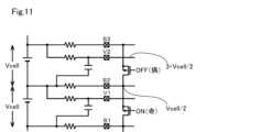
ところで、出願人は特許文献1において、組電池を構成する各電池セルに対応して設けられるRCフィルタ及び放電用抵抗について、新規な接続形態を提案している。 By the way, in
図11に示すように、特許文献1の接続形態では、奇数番目に位置する放電用スイッチをオンすると端子S2の電圧がVcell/2となるため、その1段上で偶数番目の端子V2-S2間の電圧が(3・Vcell/2)となる。この場合、電圧検出装置への入力電圧が過大となってしまう。 As shown in FIG. 11, in the connection configuration of
本発明は上記事情に鑑みてなされたものであり、その目的は、特定のRCフィルタ及び放電用抵抗の接続形態を採用した測定系においても、電圧検出装置への入力電圧が過大となることを回避しつつ故障判定を行うことができる組電池監視システム及び組電池の故障判定方法を提供することにある。 The present invention has been made in view of the above circumstances, and its object is to prevent the input voltage to the voltage detection device from becoming excessive even in a measurement system that employs a specific RC filter and discharge resistor connection configuration. It is an object of the present invention to provide an assembled battery monitoring system and an assembled battery failure determination method capable of performing failure determination while avoiding failures.
請求項1記載の組電池監視システムによれば、電圧検出装置には、1つの電池セルに対応して設けられる第1~第3端子がそれぞれ接続用スイッチを介して接続される。第2及び第3端子は、電池セルに並列に接続されるRCフィルタの出力端子を介して当該電池セルの電圧を検出するために使用される。放電用抵抗素子は、電池セルの正側,負側の各端子と第1,第3端子との間にそれぞれ接続され、放電用スイッチは第1,第3端子間に接続される。これにより、放電用スイッチがオンされると、2つの放電用抵抗素子を介した電池セルの放電経路が形成される。尚、負側端子と正側端子とが共通になる2つの電池セルについては、上段のセルの第3端子が下段のセルの第1端子になる。 According to the assembled battery monitoring system of
制御装置は、各電池セルの端子電圧を検出した結果と、複数の放電用スイッチを偶数番目に並ぶものと、奇数番目に並ぶものとをそれぞれ同時にオンした際に、対応する電池セルについて検出される電圧の差を閾値と比較することで放電用スイッチの故障判定を行う。また、前記対応する電池セルについて検出される電圧を閾値と比較することで、RCフィルタに接続されるハーネスの故障判定を行う。このように構成すれば、電池セルの電圧をVcellとすると、それぞれのケースで偶数番目,奇数番目の電池セルについて電圧をVcell/2が検出されることで、測定系が正常であることが確認できる。この時、制御装置は、測定対象の電池セルに対応する第2及び第3端子が、電圧検出装置の入力端子に順次接続されるように接続用スイッチを制御すれば良い。これにより、電圧検出装置に過大な電圧が入力されることを回避できる。When the terminal voltage of each battery cell is detected and the discharge switches of the even-numbered and odd-numbered discharge switches are simultaneously turned on, the control device detects the terminal voltage of the corresponding battery cell. The failureof the discharge switch is determined by comparing the voltage difference between the two voltages with a threshold value . Further,by comparing the voltage detected for the corresponding battery cell with a threshold value, failure determination of the harness connected to the RC filter is performed. With this configuration, if the voltage of the battery cell is Vcell, the voltage of Vcell/2 is detected for the even-numbered and odd-numbered battery cells in each case, thereby confirming that the measurement system is normal. can. At this time, the control device may control the connection switch so that the second and third terminals corresponding to the battery cell to be measured are sequentially connected to the input terminal of the voltage detection device. As a result, it is possible to prevent an excessive voltage from being input to the voltage detection device.
更に、放電用スイッチのショート故障やオープン故障,放電用抵抗素子のオープン故障や第2,第3端子のオープン,ショート故障等を検出できる。Furthermore , it is possible to detect short-circuit failures and open-circuit failures of the discharge switch, open-circuit failures of the discharge resistance element, open-circuit failures of the second and third terminals, and the like.
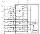
以下、一実施形態について説明する。図1に示すように、組電池1は、二次電池である複数個の電池セル2(1,2,3,…)が多段直列接続されて構成されている。電圧監視IC3は、各電池セル2の正側,負側端子に対応した接続端子9,4を備え、接続端子4は放電用抵抗素子5を介して、対応する電池セル2の負側端子にそれぞれ接続されている。電圧監視IC3は電圧監視装置に相当する。 An embodiment will be described below. As shown in FIG. 1, the assembled
各電池セル2の正側端子,負側端子には、抵抗素子6及びコンデンサ7の直列回路が接続されており、これらはRCフィルタ8を構成している。接続端子9には、抵抗素子6及びコンデンサ7の共通接続点であるRCフィルタ8の出力端子が接続されている。NチャネルMOSFETで構成される放電用スイッチ10は、電圧監視IC3の内部において、対応する電池セル2の接続端子4と、その一段上に位置する電池セル2の接続端子4との間に接続されている。一段上の電池セル2の負側端子は、その下の電池セル2の正側端子と共通であるから、放電用スイッチ10は、対応する電池セル2の正側,負側端子間に、それぞれ放電用抵抗素子5を介して接続されている。 A series circuit of a
電圧監視IC3は、制御装置11及び電圧検出装置12を備えている。電圧検出装置12は、例えばA/Dコンバータである。各電池セル2に対応する接続端子9及び4は、それぞれ接続用スイッチ13及び14を介して電圧検出装置12の各入力端子に共通に接続されている。制御装置11は、接続用スイッチ13及び14のON/OFFを制御して、電圧検出装置12に各電池セル2の電圧を個別に検出させる。その検出結果は、制御装置11に入力される。また制御装置11は、放電用スイッチ10のON/OFFを制御して各電池セル2の電圧均等化処理を行う。以上が組電池監視システム15を構成している。 The
ここで、例えば電池セル2(1)について見ると、接続端子4(2),9(1),4(1)がそれぞれ第1,第2,第3端子に相当する。また、電池セル2(2)について見ると、接続端子4(3),9(2),4(2)がそれぞれ第1,第2,第3端子に相当する。また、これらの端子については、測定対象とする電圧を明確にするため、接続端子9(1),4(1)をそれぞれ端子V1,S1と称し、接続端子9(2),4(2)をそれぞれ端子V2,S2と称す場合がある。 Here, for the battery cell 2(1), for example, the connection terminals 4(2), 9(1) and 4(1) correspond to the first, second and third terminals, respectively. Also, when looking at the battery cell 2(2), the connection terminals 4(3), 9(2) and 4(2) correspond to the first, second and third terminals, respectively. For these terminals, in order to clarify the voltage to be measured, connection terminals 9(1) and 4(1) are referred to as terminals V1 and S1, respectively, and connection terminals 9(2) and 4(2) are referred to as terminals V1 and S1, respectively. are sometimes referred to as terminals V2 and S2, respectively.
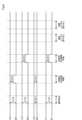
次に、本実施形態の作用について説明する。図2に示すように、本実施形態の診断シーケンスは、先ず各電池セル2の電圧を検出する「通常検出」を行う。これが第1ステップに相当する。対応する検出状態を図3Aに示す。検出結果は、制御装置11内部の通常レジスタに格納される。次に、偶数番目に並ぶ放電用スイッチ10だけをONさせる「放電用SW診断偶数」を行う。これが第2ステップに相当する。この時、接続用スイッチ13,14のオンオフを順次切り替えて偶数番目に並ぶ電池セル2の電圧をそれぞれ検出し、検出結果を制御装置11内部の診断レジスタ(偶数)に格納する。対応する検出状態を図3Bに示す。 Next, the operation of this embodiment will be described. As shown in FIG. 2, the diagnostic sequence of this embodiment first performs "normal detection" for detecting the voltage of each
次に、奇数番目に並ぶ放電用スイッチ10だけをONさせる「放電用SW診断奇数」を行う。これが第3ステップに相当する。この時も、接続用スイッチ13,14のオンオフを順次切り替えて奇数番目に並ぶ電池セル2の電圧をそれぞれ検出し、検出結果を制御装置11内部の診断レジスタ(奇数)に格納する。対応する検出状態を図3Cに示す。それから、制御装置11は、通常レジスタ,診断レジスタに格納された各電圧値を比較して判定を行う。これらの「通常レジスタ読み出し」,「診断レジスタ読み出し」,「比較判定」が第4ステップに相当する。尚、「放電用SW診断偶数」と「放電用SW診断奇数」の順序を入れ替えても良いことは言うまでもない。 Next, the “discharge SW diagnosis odd number” is performed to turn ON only the discharge switches 10 arranged in the odd-numbered order. This corresponds to the third step. Also at this time, the connection switches 13 and 14 are sequentially turned on and off to detect the voltages of the odd-numbered
図4に示すように正常であれば、「通常検出」では各電池セル2の電圧Vcellが検出され、「放電用SW診断偶数」,「放電用SW診断奇数」では、それぞれ偶数番目,奇数番目の電池セル2について電圧Vcell/2が検出される。 As shown in FIG. 4, if normal, the voltage Vcell of each
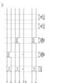
例えば図5Aに示すように、放電用スイッチ10(2)がショート故障,つまりON状態で固着すると、端子S3,S2の電位がVcell/2となる。そのため、図6に示すように、「通常検出」,「放電用SW診断偶数」の何れの測定結果もVcell/2となるので、放電用スイッチ10(2)のショート故障を判定できる。この場合「比較判定」では、「通常レジスタ読み出し」の値を0.5倍したものと、「診断レジスタ読み出し」の値との差の絶対値をとり、その結果をゼロ付近に設定される閾値と比較することで行う。これを「差分比較」と称する。 For example, as shown in FIG. 5A, if the discharge switch 10(2) is short-circuited, that is, stuck in the ON state, the potentials of the terminals S3 and S2 become Vcell/2. Therefore, as shown in FIG. 6, the measurement results of both "normal detection" and "discharge SW diagnosis even" are Vcell/2, so it is possible to determine the short failure of the discharge switch 10(2). In this case, in the "comparison judgment", the absolute value of the difference between the "normal register read" value multiplied by 0.5 and the "diagnostic register read" value is taken, and the result is set to a threshold value near zero. This is done by comparing with This is called "difference comparison".
また、例えば図5Bに示すように、RCフィルタ8の出力端子と端子V2との間を接続するハーネスが断線してオープンになると、端子V2に電位が発生しない。そのため、図7に示すように、「通常検出」,「放電用SW診断偶数」の何れの測定結果もゼロとなるので、ハーネスの断線を判定できる。この場合「比較判定」では、「診断レジスタ読み出し」の値をゼロ付近に設定される閾値と比較することで行う。これを「絶対値比較」と称する。また、「通常検出」,「放電用SW診断偶数」の測定結果の差をゼロ付近の閾値と比較して「差分比較」を行っても良い。尚、端子V2,S2間がショート故障した場合も同様の結果となる。 For example, as shown in FIG. 5B, if the harness connecting between the output terminal of the
例えば図5Cに示すように、放電用スイッチ10(2)がオープン故障,つまりOFF状態で固着すると、端子V2,S2の電位がVcell/2に変化しない。そのため、図8に示すように、「放電用SW診断偶数」の測定結果がVcellとなるので、放電用スイッチ10(2)のオープン故障を判定できる。この場合「比較判定」では、「通常レジスタ読み出し」の値と「診断レジスタ読み出し」の値との差の絶対値をとり、その結果をゼロ付近に設定される閾値と比較することで行う。これも「差分比較」である。尚、放電用抵抗素子5(3)と端子S3との間を接続するハーネスが断線してオープンになった場合も同様の結果となる。 For example, as shown in FIG. 5C, if the discharge switch 10(2) has an open failure, that is, stuck in the OFF state, the potentials of the terminals V2 and S2 do not change to Vcell/2. Therefore, as shown in FIG. 8, the measurement result of the "discharge SW diagnosis even number" is Vcell, so that the open failure of the discharge switch 10(2) can be determined. In this case, the "comparison determination" is performed by taking the absolute value of the difference between the "normal register read" value and the "diagnostic register read" value, and comparing the result with a threshold set near zero. This is also a "difference comparison". The same result is obtained when the harness connecting the discharge resistance element 5(3) and the terminal S3 is disconnected and becomes open.
また、例えば図5Dに示すように、RCフィルタ8(2)のコンデンサ7(2)がショート故障すると、端子V2が電池セル2の負側端子の電位になる。したがって、図9に示すように、「通常検出」の測定結果がゼロとなる。また、「放電用SW診断偶数」の測定結果は、-Vcell/2となる。これにより、コンデンサ7(2)のショート故障を判定できる。この場合「比較判定」では、「診断レジスタ読み出し」の値をゼロ付近の負の値に設定される閾値と比較することで行う。尚、抵抗素子6(2)の出力側端子が電池セル2の負側端子にショートした場合も同様の結果となる。Also, as shownin FIG. 5D, for example, when the capacitor 7(2) of the RC filter 8(2) short-circuits, the terminal V2 becomes the potential of the negative terminal of the
以上のように本実施形態によれば、電圧検出装置12には、電池セル2に対応して設けられる接続端子9,4がそれぞれ接続用スイッチ13,14を介して接続される。接続端子9,4は、RCフィルタ8の出力端子を介して電池セル2の電圧を検出するために使用される。放電用抵抗素子5は、電池セル2の正側,負側の各端子と接続端子9,4との間にそれぞれ接続され、放電用スイッチ10は接続端子4(n+1),4(n)間に接続される。nは自然数である。 As described above, according to the present embodiment, the
制御装置11は、複数の放電用スイッチ10を偶数番目に並ぶものと、奇数番目に並ぶものとをそれぞれ同時にオンした際に、対応する電池セル2について検出される電圧に基づいて故障判定を行う。このように構成すれば、「放電用SW診断偶数」,「放電用SW診断奇数」の測定結果が何れもVcell/2となることで、測定系が正常であることが確認できる。そして、電圧検出装置12に過大な電圧が入力されることを回避できる。 When the even-numbered discharge switches 10 and the odd-numbered discharge switches 10 are turned on at the same time, the
また、制御装置は、「通常検出」の測定結果と、「放電用SW診断偶数」又は「放電用SW診断奇数」の測定結果との差に基づいて故障判定を行う。これにより、放電用スイッチ10のショート故障やオープン故障,放電用抵抗素子5のオープン故障や接続端子9,4又はそれらに対応するハーネスのオープン故障等を検出できる。 Further, the control device performs failure determination based on the difference between the measurement result of "normal detection" and the measurement result of "discharge SW diagnosis even number" or "discharge SW diagnosis odd number". This makes it possible to detect a short-circuit failure or open failure of the
(その他の実施形態)
各電池セル2の正側端子とRCフィルタ8等との間にインダクタを挿入したり、電池セル2に並列にツェナーダイオードや平滑コンデンサを接続しても良い。
各スイッチを構成する素子は、FETやバイポーラトランジスタ,アナログスイッチ等何れでも良い。
本開示は、実施例に準拠して記述されたが、本開示は当該実施例や構造に限定されるものではないと理解される。本開示は、様々な変形例や均等範囲内の変形をも包含する。加えて、様々な組み合わせや形態、さらには、それらに一要素のみ、それ以上、あるいはそれ以下、を含む他の組み合わせや形態をも、本開示の範疇や思想範囲に入るものである。(Other embodiments)
An inductor may be inserted between the positive terminal of each
An element constituting each switch may be an FET, a bipolar transistor, an analog switch, or the like.
Although the present disclosure has been described with reference to examples, it is understood that the present disclosure is not limited to such examples or structures. The present disclosure also includes various modifications and modifications within the equivalent range. In addition, various combinations and configurations, as well as other combinations and configurations, including single elements, more, or less, are within the scope and spirit of this disclosure.
図面中、1は組電池、2は電池セル、3は電圧監視IC、4は接続端子、5は放電用抵抗素子、6は抵抗素子、7はコンデンサ、8はRCフィルタ、9は接続端子、10は放電用スイッチ、11は制御装置、12は電圧検出装置である。 In the drawings, 1 is an assembled battery, 2 is a battery cell, 3 is a voltage monitoring IC, 4 is a connection terminal, 5 is a discharge resistance element, 6 is a resistance element, 7 is a capacitor, 8 is an RC filter, 9 is a connection terminal, 10 is a discharge switch, 11 is a control device, and 12 is a voltage detection device.
Claims (2)
Translated fromJapanese前記各電池セルと前記電圧検出装置との間にそれぞれ接続される放電用抵抗素子(5)及びRCフィルタ(8)と、
前記各電池セルに対応して配置され、対応する電池セルを放電させる放電用スイッチ(10)と、
前記放電用スイッチのオンオフを制御する制御装置(11)とを備え、
前記RCフィルタは、対応する電池セルに並列に接続され、
1つの電池セルに対応して第1~第3端子(9,4)が設けられ、
前記電圧検出装置には、前記第1~第3端子がそれぞれ接続用スイッチ(13,14)を介して接続され、
前記制御装置は、前記接続用スイッチのオンオフも制御し、
前記第2及び第3端子は、前記RCフィルタの出力端子を介して前記電池セルの電圧を検出するために使用され、
前記放電用抵抗素子は、前記電池セルの正側,負側の各端子と前記第1,第3端子との間にそれぞれ接続され、
前記放電用スイッチは、前記第1,第3端子間に接続され、
前記制御装置は、各電池セルの端子電圧を検出した結果と、前記複数の放電用スイッチを偶数番目に並ぶものと、奇数番目に並ぶものとをそれぞれ同時にオンした際に、対応する電池セルについて検出される電圧との差を閾値と比較することで、前記放電用スイッチの故障判定を行い、前記対応する電池セルについて検出される電圧を閾値と比較することで、前記RCフィルに接続されるハーネスの故障判定を行う組電池監視システム。A voltage detection device (12) for detecting the voltage of each battery cell in an assembled battery (1) configured by connecting a plurality of battery cells (2) in series in multiple stages;
a discharge resistance element (5) and an RC filter (8) respectively connected between each battery cell and the voltage detection device;
a discharge switch (10) disposed corresponding to each battery cell for discharging the corresponding battery cell;
A control device (11) for controlling on/off of the discharge switch,
the RC filters are connected in parallel to corresponding battery cells;
First to third terminals (9, 4) are provided corresponding to one battery cell,
The first to third terminals are connected to the voltage detection device via connection switches (13, 14), respectively,
The control device also controls on/off of the connection switch,
the second and third terminals are used to sense the voltage of the battery cell via the output terminal of the RC filter;
The discharge resistance element is connected between each of positive and negative terminals of the battery cell and the first and third terminals,
The discharge switch is connected between the first and third terminals,
Whenthe result of detecting the terminal voltage of each battery cell and the even-numbered discharge switches and the odd-numbered discharge switches are turned on at the same time, the control device detects the corresponding battery cell.By comparing the difference from the detected voltage with a threshold value, the failure determinationof the discharge switch is performed. Assembled battery monitoring systemthat judges the failure of the harness .
前記各電池セルに対応して配置され、対応する電池セルを放電させる放電用スイッチと
を備え、
前記RCフィルタは、対応する電池セルに並列に接続され、
前記第2及び第3端子を、前記RCフィルタの出力端子を介して前記電池セルの電圧を検出するために使用し、
前記第1及び第3端子を、前記放電用スイッチがオンされた際に前記電池セルの放電経路を形成するために使用し、
前記放電用抵抗素子は、前記電池セルの正側,負側の各端子と前記第1,第3端子との間にそれぞれ接続されている構成において、
各電池セルの端子電圧を検出した結果と、前記複数の放電用スイッチを偶数番目に並ぶものと、奇数番目に並ぶものとをそれぞれ同時にオンした際に、対応する電池セルについて検出される電圧との差を閾値と比較することで前記放電用スイッチの故障判定を行い、前記対応する電池セルについて検出される電圧を閾値と比較することで、前記RCフィルタに接続されるハーネスの故障判定を行う組電池の故障判定方法。Discharging resistance elements and RC filters respectively connected between each battery cell and first to third terminals corresponding to each battery cell in an assembled battery configured by connecting a plurality of battery cells in series in multiple stages ,
A discharge switch arranged corresponding to each battery cell and discharging the corresponding battery cell,
the RC filters are connected in parallel to corresponding battery cells;
using the second and third terminals to sense the voltage of the battery cell via the output terminal of the RC filter;
using the first and third terminals to form a discharge path for the battery cell when the discharge switch is turned on;
In a configuration in which the discharge resistive element is connected between each of the positive and negative terminals of the battery cell and the first and third terminals,
The result of detecting the terminal voltage of each battery cell, and the voltage detected for the corresponding battery cell when the even-numbered discharge switches and the odd-numbered discharge switches are turned on at the same time. Failure determinationof the discharge switchis performed by comparing the difference with a threshold, and failure determination of the harness connected to the RC filter is performed by comparing the voltage detected for the corresponding battery cell with the threshold. A failure determination method forassembled batteries.
Priority Applications (1)
| Application Number | Priority Date | Filing Date | Title |
|---|---|---|---|
| JP2019144636AJP7331543B2 (en) | 2019-08-06 | 2019-08-06 | BUILD BATTERY MONITORING SYSTEM AND BATTERY FAILURE DETERMINATION METHOD |
Applications Claiming Priority (1)
| Application Number | Priority Date | Filing Date | Title |
|---|---|---|---|
| JP2019144636AJP7331543B2 (en) | 2019-08-06 | 2019-08-06 | BUILD BATTERY MONITORING SYSTEM AND BATTERY FAILURE DETERMINATION METHOD |
Publications (2)
| Publication Number | Publication Date |
|---|---|
| JP2021027720A JP2021027720A (en) | 2021-02-22 |
| JP7331543B2true JP7331543B2 (en) | 2023-08-23 |
Family
ID=74663233
Family Applications (1)
| Application Number | Title | Priority Date | Filing Date |
|---|---|---|---|
| JP2019144636AActiveJP7331543B2 (en) | 2019-08-06 | 2019-08-06 | BUILD BATTERY MONITORING SYSTEM AND BATTERY FAILURE DETERMINATION METHOD |
Country Status (1)
| Country | Link |
|---|---|
| JP (1) | JP7331543B2 (en) |
Citations (4)
| Publication number | Priority date | Publication date | Assignee | Title |
|---|---|---|---|---|
| JP2010228523A (en) | 2009-03-26 | 2010-10-14 | Hitachi Ltd | Battery system for vehicles |
| JP2012122856A (en) | 2010-12-08 | 2012-06-28 | Toshiba Corp | Battery pack device |
| JP2017112677A (en) | 2015-12-15 | 2017-06-22 | 株式会社デンソー | Battery pack monitoring system |
| JP2017208880A (en) | 2016-05-16 | 2017-11-24 | 株式会社デンソー | Battery pack monitoring system |
- 2019
- 2019-08-06JPJP2019144636Apatent/JP7331543B2/enactiveActive
Patent Citations (4)
| Publication number | Priority date | Publication date | Assignee | Title |
|---|---|---|---|---|
| JP2010228523A (en) | 2009-03-26 | 2010-10-14 | Hitachi Ltd | Battery system for vehicles |
| JP2012122856A (en) | 2010-12-08 | 2012-06-28 | Toshiba Corp | Battery pack device |
| JP2017112677A (en) | 2015-12-15 | 2017-06-22 | 株式会社デンソー | Battery pack monitoring system |
| JP2017208880A (en) | 2016-05-16 | 2017-11-24 | 株式会社デンソー | Battery pack monitoring system |
Also Published As
| Publication number | Publication date |
|---|---|
| JP2021027720A (en) | 2021-02-22 |
Similar Documents
| Publication | Publication Date | Title |
|---|---|---|
| JP6477593B2 (en) | Battery pack monitoring system | |
| JP5169491B2 (en) | Battery pack monitoring device and battery breakage detection method | |
| JP5224095B2 (en) | Battery management device for battery pack | |
| US10416238B2 (en) | Electrochemical cell monitoring and balancing circuit with self-diagnostic feature | |
| JP5989620B2 (en) | Battery pack module and disconnection detection method | |
| JP6627635B2 (en) | Voltage measurement device and voltage measurement method, and voltage control device and voltage control method | |
| EP3575809B1 (en) | A method of operating battery management systems, corresponding device and vehicle | |
| US20120146652A1 (en) | Assembled battery system and failure detection method of assembled battery system | |
| US8836341B2 (en) | Semiconductor circuit, semiconductor device, method of diagnosing abnormality of wire, and computer readable storage medium | |
| US20140266050A1 (en) | Balance resistor and low pass filter | |
| US10288694B2 (en) | Secondary battery monitoring device and method for diagnosing failure | |
| JP2002281681A (en) | Monitoring method for battery pack dc voltage detector | |
| JP7014565B2 (en) | Secondary battery monitoring device and failure diagnosis method | |
| CN112913105A (en) | Battery pack and charging method for battery pack | |
| US20210208201A1 (en) | Battery monitoring device | |
| JP6324333B2 (en) | Cell balance circuit and fault diagnosis device thereof | |
| CN113748353A (en) | Device and method for diagnosing battery cell | |
| JP4048970B2 (en) | Flying capacitor voltage detection circuit | |
| KR102861599B1 (en) | ISOLATION STATE diagnosis METHOD AND BATTERY SYSTEM USING THE SAME | |
| JP7331543B2 (en) | BUILD BATTERY MONITORING SYSTEM AND BATTERY FAILURE DETERMINATION METHOD | |
| JP2017158269A (en) | Voltage detection apparatus | |
| JP6507989B2 (en) | Battery monitoring device | |
| JP5684535B2 (en) | Semiconductor circuit, semiconductor device, failure diagnosis method, and failure diagnosis program | |
| JP4571888B2 (en) | Voltage measuring device and degradation determination method thereof | |
| JP6536481B2 (en) | Battery monitoring system |
Legal Events
| Date | Code | Title | Description |
|---|---|---|---|
| A621 | Written request for application examination | Free format text:JAPANESE INTERMEDIATE CODE: A621 Effective date:20211116 | |
| A131 | Notification of reasons for refusal | Free format text:JAPANESE INTERMEDIATE CODE: A131 Effective date:20230131 | |
| A521 | Request for written amendment filed | Free format text:JAPANESE INTERMEDIATE CODE: A523 Effective date:20230323 | |
| TRDD | Decision of grant or rejection written | ||
| A01 | Written decision to grant a patent or to grant a registration (utility model) | Free format text:JAPANESE INTERMEDIATE CODE: A01 Effective date:20230711 | |
| A61 | First payment of annual fees (during grant procedure) | Free format text:JAPANESE INTERMEDIATE CODE: A61 Effective date:20230724 | |
| R151 | Written notification of patent or utility model registration | Ref document number:7331543 Country of ref document:JP Free format text:JAPANESE INTERMEDIATE CODE: R151 |