JP7331483B2 - Imaging control device - Google Patents
Imaging control deviceDownload PDFInfo
- Publication number
- JP7331483B2 JP7331483B2JP2019112748AJP2019112748AJP7331483B2JP 7331483 B2JP7331483 B2JP 7331483B2JP 2019112748 AJP2019112748 AJP 2019112748AJP 2019112748 AJP2019112748 AJP 2019112748AJP 7331483 B2JP7331483 B2JP 7331483B2
- Authority
- JP
- Japan
- Prior art keywords
- imaging
- captured image
- image data
- exposure period
- exposure
- Prior art date
- Legal status (The legal status is an assumption and is not a legal conclusion. Google has not performed a legal analysis and makes no representation as to the accuracy of the status listed.)
- Active
Links
Images


Classifications
- H—ELECTRICITY
- H04—ELECTRIC COMMUNICATION TECHNIQUE
- H04N—PICTORIAL COMMUNICATION, e.g. TELEVISION
- H04N23/00—Cameras or camera modules comprising electronic image sensors; Control thereof
- H04N23/70—Circuitry for compensating brightness variation in the scene
- H04N23/72—Combination of two or more compensation controls
- H—ELECTRICITY
- H04—ELECTRIC COMMUNICATION TECHNIQUE
- H04N—PICTORIAL COMMUNICATION, e.g. TELEVISION
- H04N23/00—Cameras or camera modules comprising electronic image sensors; Control thereof
- H04N23/70—Circuitry for compensating brightness variation in the scene
- H04N23/73—Circuitry for compensating brightness variation in the scene by influencing the exposure time
- B—PERFORMING OPERATIONS; TRANSPORTING
- B60—VEHICLES IN GENERAL
- B60R—VEHICLES, VEHICLE FITTINGS, OR VEHICLE PARTS, NOT OTHERWISE PROVIDED FOR
- B60R11/00—Arrangements for holding or mounting articles, not otherwise provided for
- B60R11/04—Mounting of cameras operative during drive; Arrangement of controls thereof relative to the vehicle
- H—ELECTRICITY
- H04—ELECTRIC COMMUNICATION TECHNIQUE
- H04N—PICTORIAL COMMUNICATION, e.g. TELEVISION
- H04N23/00—Cameras or camera modules comprising electronic image sensors; Control thereof
- H04N23/20—Cameras or camera modules comprising electronic image sensors; Control thereof for generating image signals from infrared radiation only
- H—ELECTRICITY
- H04—ELECTRIC COMMUNICATION TECHNIQUE
- H04N—PICTORIAL COMMUNICATION, e.g. TELEVISION
- H04N23/00—Cameras or camera modules comprising electronic image sensors; Control thereof
- H04N23/60—Control of cameras or camera modules
- H04N23/61—Control of cameras or camera modules based on recognised objects
- H—ELECTRICITY
- H04—ELECTRIC COMMUNICATION TECHNIQUE
- H04N—PICTORIAL COMMUNICATION, e.g. TELEVISION
- H04N23/00—Cameras or camera modules comprising electronic image sensors; Control thereof
- H04N23/50—Constructional details
- H04N23/54—Mounting of pick-up tubes, electronic image sensors, deviation or focusing coils
Landscapes
- Engineering & Computer Science (AREA)
- Multimedia (AREA)
- Signal Processing (AREA)
- Mechanical Engineering (AREA)
- Studio Devices (AREA)
- Exposure Control For Cameras (AREA)
Description
Translated fromJapanese本開示は、撮像制御装置に関する。 The present disclosure relates to imaging control devices.
従来、対象領域を撮像部(カメラ)で撮像した撮像画像に用いて、対象領域内に写り込んでいる物体の検出や物体の姿勢や周囲の状況等を検出して、状況把握や制御等に利用する技術が知られている。このように撮像画像を状況把握や制御に利用する場合、その精度は、撮像画像の品質に左右されやすい。例えば、周囲の環境(可視光カメラの場合は明暗差等、赤外線カメラの場合は温度差等)により、撮像画像の一部に「白飛び」や「黒つぶれ」が生じて、撮像画像の内容を正確に認識できないことがある。そのため、明るい画像と暗い画像を撮像して、合成画像を生成して、ダイナミックレンジを稼ぎ、認識性を向上させる技術が種々提案されている。 Conventionally, the target area is used in the captured image captured by the imaging unit (camera) to detect the object in the target area, the posture of the object, the surrounding situation, etc., and to grasp the situation and control the situation. The techniques used are known. When the captured image is used for situation grasping and control in this way, the accuracy is likely to be affected by the quality of the captured image. For example, depending on the surrounding environment (differences in light and shade in the case of visible light cameras, and differences in temperature in the case of infrared cameras, etc.), part of the captured image may be “blown out” or “blackened out”, and the contents of the captured image may be affected. may not be recognized accurately. Therefore, various techniques have been proposed for capturing a bright image and a dark image, generating a composite image, increasing the dynamic range, and improving recognizability.
しかしながら、上述の文献で提案されるような画像合成を行う場合、合成した後の画像のビット数が増加し処理負荷が大きくなり、高性能の処理装置が必要になったり、高処理負荷による発熱量の増加に対応するための放熱対策等が必要になったりするため、装置全体のコストが増加してしまうという問題があった。 However, when performing image synthesis as proposed in the above-mentioned document, the number of bits in the image after synthesis increases, increasing the processing load, requiring a high-performance processing device, and generating heat due to the high processing load. There is a problem that the cost of the entire device increases because heat dissipation measures or the like are required to deal with the increase in the amount.
そこで、本発明の課題の一つは、装置コストの軽減を図りつつ、撮像対象領域内の物体検出等の状況検出が精度よく実現できる撮像制御装置を提供することである。 Accordingly, one of the objects of the present invention is to provide an imaging control apparatus capable of accurately realizing situation detection such as object detection within an imaging target area while reducing the apparatus cost.
本発明の実施形態にかかる撮像制御装置は、例えば、車室内において搭乗者が乗車しうる領域を撮像可能な撮像部の露光の長さを、少なくとも第1露光期間と、上記第1露光期間より長い第2露光期間と、に制御する露光制御部と、上記第1露光期間で撮像した第1撮像画像データと、当該第1撮像画像データと同一の撮像領域を上記第2露光期間で撮像した第2撮像画像データと、を取得する画像取得部と、上記第1撮像画像データと上記第2撮像画像データとを別々に処理し、処理済みの第1撮像画像データと処理済みの第2撮像画像データとを出力する処理部と、上記処理部から出力される処理済みの上記第1撮像画像データに基づく第1撮像画像を用いて上記撮像部から近い第1領域の監視制御を行い、処理済みの上記第2撮像画像データに基づく第2撮像画像を用いて上記撮像部から上記第1領域より遠い第2領域の監視制御を実行する機器制御部と、を備える。この構成によれば、例えば、露光期間が相対的に短い第1露光期間で撮像を行うことで、撮像部に対して相対的に遠い領域で明るさが不足する画像となる可能性があるものの、撮像部に対して相対的に近い領域では、画像が明る過ぎる、いわゆる「白飛び」が生じ難くい撮像ができる。一方、露光期間が第1露光期間より相対的に長い第2露光期間で撮像を行うことで、撮像部に対して相対的に近い領域では、画像が明るすぎる可能性があるものの、撮像部から相対的に遠い領域では、画像が暗すぎる、いわゆる「黒つぶれ」が生じ難くい撮像ができる。つまり、露光期間の切り替えを行うとともに、撮像画像データを別々に扱うことで、撮像画像の合成処理を必要とすることなく、明るすぎない領域の撮像および暗すぎない領域の撮像を扱うことが可能となる。その結果、合成処理の削減による装置コストの軽減を実現するとともに、撮像部から近い領域における車室内状況を認識し易い撮像画像データ、および撮像部から遠い領域における車室内状況を認識し易い撮像画像データのいずれも精度よく取得し、監視等の制御に利用することができる。The imaging control device according to the embodiment of the present invention, for example, sets the exposure length of the imaging unit capable of imaging an area in the vehicle interior where passengers can get in at least the first exposure period to a long second exposure period, an exposure control unit for controlling a first captured image data captured during the first exposure period,and the same image capturing area as the first captured image data captured during the second exposure period. an image acquisition unit that acquires second captured image data; and an image acquisition unit that separately processes the first captured image data and the second captured image data, and processes the processed first captured image data and the processed second captured image data. a processing unitthat outputs image data; and a first captured image based on the processed first captured image data that is output from the processing unit. and a device control unit that performs monitoring control of a second area farther from the imaging unit than the first area using a second captured image based on the second captured image data that has already been processed. According to this configuration, for example, by performing imaging in the first exposure period in which the exposure period is relatively short, there is a possibility that an image with insufficient brightness in a region relatively far from the imaging unit may be obtained. In areas relatively close to the imaging unit, it is possible to perform imaging in which the image is too bright, i.e., so-called "whiteout" is less likely to occur. On the other hand, by performing imaging in the second exposure period whose exposure period is relatively longer than the first exposure period, although the image may be too bright in a region relatively close to the imaging unit, In a relatively distant area, it is possible to perform imaging in which the image is too dark, that is, so-called "blackout" is less likely to occur. In other words, by switching the exposure period and handling the captured image data separately, it is possible to capture an area that is not too bright and an area that is not too dark without the need to synthesize the captured image. becomes. As a result, it is possible to reduce the cost of the apparatus by reducing the number of synthesizing processes, and also to obtain captured image data that makes it easy to recognize the vehicle interior conditions in an area close to the imaging unit, and captured images that make it easy to recognize the vehicle interior conditions in an area far from the imaging unit. All of the data can be acquired with high accuracy and used for controlsuch as monitoring .
本発明の実施形態にかかる撮像制御装置の上記露光制御部は、例えば、上記第1露光期間と上記第2露光期間とが交互に切り替わるように制御してもよい。この構成によれば、例えば、第1撮像画像データと第2撮像画像データを効率的に取得できるとともに、第1領域の状況認識と第2領域の状況認識を実質的に同じタイミングで行うことが可能となり、状況認識をスムーズに行うことができる。 The exposure control section of the imaging control device according to the embodiment of the present invention may control, for example, such that the first exposure period and the second exposure period are alternately switched. According to this configuration, for example, the first captured image data and the second captured image data can be efficiently acquired, and the situation recognition of the first area and the situation recognition of the second area can be performed at substantially the same timing. It becomes possible, and situation recognition can be performed smoothly.
本発明の実施形態にかかる撮像制御装置の上記露光制御部は、例えば、前回撮影時に上記第1露光期間で撮像した上記第1撮像画像データにおいて上記第1領域の平均輝度値に基づき、今回撮像時の上記第1露光期間の長さを補正し、前回撮影時に上記第2露光期間で撮像した前記第2撮像画像データにおいて上記第2領域の平均輝度値に基づき、今回撮像時の上記第2露光期間の長さを補正するようにしてもよい。この構成によれば、例えば、撮像時の周囲の条件変化に対応した露光期間の設定が実行しやすく、より撮像内容の認識がし易い適切な明るさで表現される第1撮像画像データおよび第2撮像画像データを取得することができる。The exposure control unit of the imaging control device according to the embodiment of the present invention, for example, based on the average luminance value ofthe first region in the first captured image data captured in the first exposure period at the time of previous imaging, this time Correcting the length of the first exposure period at the time of imaging, based on the average luminance value of thesecond area in the second captured image data captured in the second exposure period at the time of previous imaging, the above at the time of current imaging The length of the second exposure period may be corrected. According to this configuration, for example, it is easy to set the exposure period corresponding to changes in the surrounding conditions at the time of imaging, and the first captured image data and the first captured image data are expressed with appropriate brightness that makes it easier to recognize the content of the captured image. 2 captured image data can be obtained.
本発明の実施形態にかかる撮像制御装置の上記露光制御部は、例えば、上記撮像部として赤外線画像を撮像する赤外線撮像部の露光期間の長さを制御するようにしてもよい。この構成によれば、例えば、昼夜(明状態、暗状態)を問わず、車室内に搭乗者に認識されることなく、より撮像内容の認識がし易い適切な明るさで表現された第1撮像画像データおよび第2撮像画像データを取得することができる。 The exposure control section of the imaging control apparatus according to the embodiment of the present invention may control, for example, the length of the exposure period of an infrared imaging section that captures an infrared image as the imaging section. According to this configuration, for example, regardless of whether it is day or night (bright state or dark state), the first image is expressed with an appropriate brightness that makes it easier to recognize the imaged content without being recognized by the passenger in the vehicle interior. Captured image data and second captured image data can be obtained.
本発明の実施形態にかかる撮像制御装置の上記露光制御部は、例えば、上記赤外線撮像部の撮像可能な領域に照射する赤外光の照射期間を上記第1露光期間および上記第2露光期間と同期させるようにしてもよい。この構成によれば、例えば、撮像時のみに赤外光の照射を実施することができるので、撮像コストの軽減に寄与できるとともに、発熱量の軽減が可能になり、熱対策構造の簡略化に寄与することができる。 The exposure control unit of the imaging control device according to the embodiment of the present invention, for example, sets the irradiation period of the infrared light irradiated to the imageable region of the infrared imaging unit to the first exposure period and the second exposure period. You may make it synchronize. According to this configuration, for example, it is possible to irradiate infrared light only at the time of imaging, so that it is possible to contribute to the reduction of the imaging cost, the amount of heat generated can be reduced, and the heat countermeasure structure can be simplified. can contribute.
以下、本開示の実施形態を図面に基づいて説明する。以下に説明される実施形態の構成、ならびに当該構成によってもたらされる作用および効果は、あくまで一例であって、以下の記載内容に限られるものではない。 Hereinafter, embodiments of the present disclosure will be described based on the drawings. The configurations of the embodiments described below and the actions and effects brought about by the configurations are merely examples, and are not limited to the following descriptions.
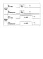
図1は、実施形態にかかる撮像制御装置の適用対象としての車両10の構成および車両10における撮像部の撮像範囲を説明するための例示的かつ模式的な図である。 FIG. 1 is an exemplary and schematic diagram for explaining the configuration of a
本実施形態における撮像制御装置は、車両10の車室10a内の状況を検出(認識)するための撮像画像データを取得するための制御を行う。車室10a内の状況とは、例えば、車室10aに搭乗者が存在するか否か(搭乗状況)、搭乗者の姿勢状況、搭乗者の車室10aにおける装備の利用状況等である。また、車室10a内の状況には、車室10a内に持ち込まれた物体(荷物、生き物等)の有無状況等も含むことができる。 The imaging control device according to the present embodiment performs control for acquiring captured image data for detecting (recognizing) the situation inside the
本実施形態において、撮像制御装置(撮像制御部)を搭載する車両10は、例えば、不図示の内燃機関を駆動源とする自動車、すなわち内燃機関自動車であってもよいし、不図示の電動機を駆動源とする自動車、すなわち電気自動車や燃料電池自動車等であってもよい。また、それらの双方を駆動源とするハイブリッド自動車であってもよいし、他の駆動源を備えた自動車であってもよい。 In the present embodiment, the
図1に例示されるように、車両10は、不図示の搭乗者(運転者、同乗者)が乗車する車室10aを構成している。車室10a内には、例えば、ステアリングホイール12と対面する位置に運転者用のシート14a(運転席)、シート14aの隣に同乗者用のシート14b(助手席)が、前列シート14(前席)として配置されている。また、例えば、同乗者用のシート16a,16b,16cが、後列シート16(後席)として配置されている。なお、図1では、前列シート14を2シート、後列シート16を3シートとする5シート(5人乗り)の例を示すが、シートレイアウトは、例えば、車種等に応じて適宜選択可能である。例えば、後列シート16を2シート(前列シート14と合わせて4人乗り)で構成してもよい。また、3列シート構成でもよいし、3列以上の構成でもよい。また、搭搭乗者用としては前列シート14の1列構成として、前列シート14の後方は荷物スペースとして構成してもよい。 As illustrated in FIG. 1, a
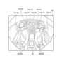
図2は、実施形態にかかる撮像制御装置を搭載する車両10における前列シート14(シート14a)に着座した搭乗者18の撮像の様子および撮像部の配置を説明する例示的かつ模式的な図である。 FIG. 2 is an exemplary and schematic diagram for explaining how an
前列シート14(シート14a)は、シートクッション14c、シートバック14d、ヘッドレスト14e等で構成され、シートクッション14cを支持するフレームが図示しない、レールによって車室10aの床面に車両前後方向に位置調整可能固定されている。また、前列シート14には、リクライニング機構等の各種調整機構が設けられ、シートベルト20を装着し、ステアリングホイール12を把持する搭乗者18(運転者)の姿勢を運転に適した状態に維持し易いように調整できるように構成されている。 The front row seat 14 (
前述したように、本実施形態の撮像制御装置は、車室10a内の状況を検出(認識)するために、車室10a内を見渡せる位置に撮像部として、例えば赤外線撮像部22が配置されている。また、赤外線撮像部22の近傍には、赤外線照射部24が配置されている。本実施形態の場合、赤外線撮像部22および赤外線照射部24は、車両10のフロントウインドウの内側上部のほぼ中央部(例えば、バックビューミラーの付近)に配置されている。なお、赤外線撮像部22は、車室10a内を見渡せる位置であれば、他の位置に配置されてもよい。また、赤外線撮像部22の撮像領域の全体に赤外光を照射できれば、赤外線照射部24の位置も適宜変更可能であり、赤外線撮像部22と赤外線照射部24とを異なる位置に配置してもよい。また、赤外線撮像部22と赤外線照射部24とは、一体のカメラユニットとして構成されてもよい。 As described above, in order to detect (recognize) the situation in the
赤外線撮像部22は、例えば、赤外線による撮影に対応した、CCD(Charge Coupled Device)やCIS(CMOS image sensor)等の撮像素子を内蔵するデジタルカメラである。赤外線撮像部22は、所定のフレームレートで動画データ(撮像画像データ)を逐次出力することができる。赤外線照射部24は、例えば、赤外線を照射するLED(Light Emitting Diode)ライト等とすることがでる。赤外線撮像部22は、図1にハッチングを付して示すように、例えば、車室10a内において搭乗者18が乗車しうる領域(前列シート14、後列シート16のある領域)を1台で撮像可能である。また、赤外線照射部24は、赤外線撮像部22の撮像範囲を少なくとも含む領域に赤外光を照射できるように照射角および照射強度が設定されている。 The
赤外線撮像部22は、その撮像領域に、少なくとも前列シート14、後列シート16に着座する各搭乗者18が含まれるように、視野角および姿勢が調整されて固定されている。赤外線撮像部22の撮像領域には、例えば、図2に示すように、シート14a(運転席)に搭乗者18が着座している場合、その搭乗者18の顔および少なくとも上半身が含まれる。同様に、シート14b(助手席)に搭乗者18が着座している場合、その搭乗者18の顔および少なくとも上半身が含まれる。また、後列シート16のシート16a~16cに搭乗者18が着座している場合、その搭乗者18の顔および少なくとも上半身が含まれる。 The
赤外線照射部24は、シート14a,シート16a等に着座した搭乗者18に赤外光を照射するが、人の眼には光として認識されないため、赤外線が搭乗者18の顔の方向に照射されても、搭乗者18にまぶしさを感じさせない。したがって、搭乗者18の車室10a内における快適性を確保しつつ、赤外線撮像部22による搭乗者18等の撮像が容易に実現できる。 The
ところで、図1に示すように、赤外線撮像部22および赤外線照射部24が車室10aの前方部分に配置されている場合、撮像される赤外線撮像画像で前列シート14および後列シート16の全領域について、その撮像内容を識別できる程度の撮像品質が得られない場合がある。例えば、赤外線撮像部22から後列シート16までの距離が前列シート14までの距離より大きいため、撮像された赤外線画像は、前列シート14側に比べて後列シート16側で反射光(赤外光)の減衰が大きくなるため暗くなる傾向がある。この場合、赤外線撮像部22に相対的に近い前列シート14の領域(以下、第1領域という場合がある)付近で、制御等で利用可能な明るさの赤外線撮像画像が得られるように撮像を行ったと仮定する。この場合、撮像された赤外線撮像画像において、赤外線撮像部22から相対的に遠い後列シート16の領域(以下、第2領域という場合がある)付近については、反射光の減衰が大きくなり「黒つぶれ」が生じる傾向が強くなる。その結果、第2領域は、制御等で利用し難い撮像画像になってしまう。逆に、後列シート16が含まれる第2領域付近で、制御等で利用可能な明るさの赤外線撮像画像が得られるように撮像を行ったと仮定する。この場合、撮像された撮像画像において、赤外線撮像部22に相対的に近い前列シート14が含まれる第1領域付近については、反射光の減衰が小さいので受光量が増加して、「白飛び」してしまう傾向が強くなる。その結果、第1領域については、制御等で利用し難い撮像画像になってしまう。 By the way, as shown in FIG. 1, when the
そこで、本実施形態の撮像制御装置では、車室10a内を赤外線撮像部22で逐次撮像して所定のフレームレートで赤外線撮像画像データ(以下、単に撮像画像データと記す)を出力する際に、前列シート14が含まれる第1領域用に露光して撮像した第1撮像画像データと、後列シート16が含まれる第2領域用に露光して撮像した第2撮像画像データを、例えば交互に出力するように露光制御を行う。つまり、前列シート14用として、第1領域が適切な明るさで表現できる赤外線撮像された第1撮像画像データと、後列シート16用として、第2領域が適切な明るさで表現される赤外線撮影された第2撮像画像データと、を取得し、それぞれの撮像画像データを独立的に処理し(扱い)、例えば、各種監視制御に利用する。第1撮像画像データおよび第2撮像画像データを用いた監視制御としては、例えば、搭乗者18や搭載物の有無検出制御やその識別制御、シートベルト20の装着の有無検出制御および未装着の場合の警告制御、搭乗者18が車載機器を操作する場合のジェスチャ検出制御等である。また、車室10a内の忘れ物検出制御等にも利用できる。また、第1撮像画像データおよび第2撮像画像データの解析をさらに行うことで、例えば、運転者の眠気レベルの判定やエアバックの制御、前列シート14や後列シート16に着座する搭乗者18の識別、例えば、大人男性、大人女性、子供等の識別を行い、それぞれに適した制御を実行することもできる。なお、これらの場合、第1撮像画像データと第2撮像画像データとの合成処理を行わず、各撮像画像データをそれぞれ制御に利用する。その結果、画像の合成処理が不要となり、処理負荷の軽減が可能となり、装置コストの低減に寄与できる。 Therefore, in the imaging control device of the present embodiment, when the
図3は、上述したような撮像制御を実行する撮像制御装置(撮像制御部)の構成を示す例示的かつ模式的なブロック図である。なお、図3は、撮像制御装置(撮像制御部)として機能するECU26(Electronic Control Unit)に、当該撮像制御装置が取得した第1撮像画像データと第2撮像画像データを用いて、車両10における種々の監視制御を実行する機器制御部28が含まれる監視制御システム100を示している。 FIG. 3 is an exemplary and schematic block diagram showing the configuration of an imaging control device (imaging control section) that executes imaging control as described above. Note that FIG. 3 shows an image in the
図3に示すように、ECU26は、赤外線撮像部22および赤外線照射部24を制御して撮像を実行するとともに、取得した第1撮像画像データや第2撮像画像データを機器制御部28に提供する。そして、機器制御部28は、車内ネットワーク30を介して電気的に接続された出力装置32や車載機器34の制御を実行する。車内ネットワーク30は、例えば、CAN(Controller Area Network)として構成されている。また、車内ネットワーク30は、機器制御部28で制御を実行する際に参照する各種センサが電気的に接続されている。図3の場合、一例として、前列シート14、後列シート16に装備されるシートベルト20の装着の有無を検出するシートベルトセンサ36(36a~36e)が示されている。 As shown in FIG. 3, the
ECU26は、例えば、機器制御部28、CPU38(Central Processing Unit)の他、ROM40(Read Only Memory)、RAM42(Random Access Memory)、SSD44(Solid State Drive、フラッシュメモリ)等を有している。CPU38は、例えば、ROM40等の不揮発性の記憶装置にインストールされ記憶されたプログラムを読み出し、当該プログラムにしたがって演算処理を実行することができる。RAM42は、CPU38での演算で用いられる各種のデータを一時的に記憶する。SSD44は、書き換え可能な不揮発性の記憶部であって、ECU26の電源がオフされた場合にあってもデータを記憶することができる。なお、機器制御部28、CPU38や、ROM40、RAM42等は、同一パッケージ内に集積されうる。また、ECU26は、CPU38に替えて、DSP(Digital Signal Processor)等の他の論理演算プロセッサや論理回路等が用いられる構成であってもよい。また、SSD44に替えてHDD(Hard Disk Drive)が設けられてもよいし、SSD44やHDDは、ECU26とは別に設けられてもよい。なお、撮像制御装置(撮像制御部)として機能するECU26は、車両10を制御する複数の他のECUのCPUにおいて実現されてもよい。また、図3において、機器制御部28は、ECU26に独立的なモジュールとして実装される例が示されている。別の実施形態では、機器制御部28は、CPU38においてROM40等にインストールされたプログラムを実行することによって実現されてもよいし、ECU26とは別に、独立して設けられてもよい。 The
CPU38は、ROM40等の記憶装置にインストールされ記憶されたプログラムを読み出し、それを実行することで露光制御部38a、画像取得部38b、処理部38c等を実現する。 The
露光制御部38aは、車室10a内において搭乗者18が乗車しうる領域(前列シート14が含まれる第1領域、後列シート16が含まれる第2領域)を撮像可能な赤外線撮像部22の露光の長さを、少なくとも第1露光期間と、第1露光期間より長い第2露光期間と、に制御する。また、画像取得部38bは、第1露光期間で撮像した第1撮像画像データと、第2露光期間で撮像した第2撮像画像データと、を取得し、逐次RAM42等の記憶装置に一時的に保存する。処理部38cは、第1撮像画像データと第2撮像画像データとを別々に処理して、機器制御部28に提供して、各種制御を実行させる。 The
例えば、露光制御部38aは、第1露光期間と第2露光期間とが交互に切り替わるように、赤外線撮像部22を制御する。つまり、赤外線撮像部22の撮像した撮像画像データは、前列シート14が含まれる第1領域を認識し易い輝度で表現する(撮像する)フレームと、後列シート16が含まれる第2領域を認識し易い輝度で表現する(撮像する)フレームとが交互に存在するような動画データを構成する。例えば、奇数フレームを第1露光期間で撮像し、偶数フレームを第2露光期間で撮像する。この場合、撮像画像における輝度を例えば、0~255の256階調(「0」が暗く、「255」が明るい)で表すとする。また、予め試験等により、車室10a内の状況を認識(検出)するのに適した撮像画像の輝度は「128」であると定めていたとする。この場合、奇数フレームを撮像する場合に、第1領域の輝度の平均が例えば「128」になるように、第1露光期間を設定する。また、偶数フレームを撮像する場合に、第2領域の平均輝度が例えば「128」になるように、第2露光期間を設定する。第1露光期間による撮像を奇数フレームで行い、第2露光期間による撮像を偶数フレームで行うことにより、第1露光期間による撮像時と第2露光期間による撮像時とのタイムラグを最小限とすることができ、実質的に同じタイミングで、前列シート14が含まれる第1領域の状況と後列シート16が含まれる第2領域の状況を取得したと見なすことができる。なお、赤外線撮像部22の設置姿勢は固定されているので、撮像される撮像画像データにおける第1領域に対応する位置と第2領域に対応する位置は既知である。したがって、撮像画像データにおける第1領域と第2領域の平均輝度値の算出は容易である。 For example, the
前述したように、第1領域は、赤外線撮像部22に相対的に近いため、赤外線照射部24から赤外光が照射された場合、その反射光は相対的に減衰が小さいので第1領域示は相対的に明るくなる。したがって、図4に示すように、前列シート14側の第1領域の平均輝度を例えば「128」にするための第1露光期間は、相対的にON期間が短くなるように制御する(ラインE1)。一方、第2領域は、第1領域より赤外線撮像部22から相対的に遠いため、赤外線照射部24から赤外光が照射された場合、その反射光は相対的に減衰が大きいので第2領域は第1領域より相対的に暗くなる。したがって、図4に示すように、後列シート16側の第2領域の平均輝度を例えば「128」にするための第2露光期間のON期間は、第1露光期間より相対的に長くなるように制御する(ラインE2)。 As described above, since the first area is relatively close to the
なお、赤外線撮像部22は、物体から放射される赤外線、または物体に反射された赤外線を可視化する。そのため、撮像対象の温度や周囲の温度の変化に伴い撮像画像の輝度が変化してしまう場合がある。そこで、露光制御部38aは、RAM42等に保存されている前回撮影時に第1露光期間で撮像した第1撮像画像データにおいて赤外線撮像部22から近い第1領域の平均輝度値に基づき、今回撮像時の第1露光期間の長さを補正する。同様に、露光制御部38aは、RAM42等に保存されている前回撮影時に第2露光期間で撮像した第2撮像画像データにおいて赤外線撮像部22から第1領域より遠い第2領域の平均輝度値に基づき、今回撮像時の前記第2露光期間の長さを補正する。このように、前回撮像した撮像画像データに基づき露光期間の補正を行うことにより、例えば、撮像時の周囲の条件(例えば温度条件)が変化した場合でも、その変化に対応しやすく、より撮像内容の認識がし易い適切な明るさで表現される第1撮像画像データおよび第2撮像画像データを取得することができる。なお、補正のために参照する撮影済みの撮像画像データは、例えば、第1露光期間は、奇数フレームを、第2露光期間は偶数フレームをそれぞれ参照すればよく、過去複数回にわたり奇数フレームまたは偶数フレームを参照して露光期間の微調整を行うようにしてもよい。 Note that the
なお、露光制御部38aは、図4に示すように、第1露光期間と同期するように赤外線照射部24を第1照明駆動期間(ラインF1)で駆動して赤外線を照射し、第2露光期間と同期するように赤外線照射部24を第2照明駆動期間(ラインF2)で駆動して赤外線を照射するようにすることができる。この場合、撮像時のみに赤外光の照射を実施することになり、撮像コストの軽減に寄与できるとともに、発熱量の軽減が可能になり、熱対策構造の簡略化に寄与することができる。 Note that, as shown in FIG. 4, the
上述したように、前列シート14が含まれる第1領域と後列シート16が含まれる第2領域とで、露光期間を変更して撮像した場合の例示的かつ模式的な撮像画像データ(撮像画像)を図5および図6に示す。図5は、主として前列シート14が含まれる第1領域が制御に利用しやすい輝度で表現されるように第1露光期間で撮像した結果としての第1撮像画像データ(第1撮像画像M1)である。また、図6は、主として後列シート16が含まれる第2領域が制御に利用しやすい輝度で表現されるように第2露光期間で撮像した結果としての第2撮像画像データ(第2撮像画像M2)である。 As described above, exemplary and schematic captured image data (captured image) when the first area including the
図1に示すように、赤外線撮像部22および赤外線照射部24はフロントウインドウの内側上部のほぼ中央部に配置されているので、前列シート14(第1領域)の場合、赤外線照射部24が照射した赤外光の反射光は減衰の少ない状態で赤外線撮像部22に到達する。したがって、露光制御部38aが相対的に短い第1露光期間で赤外線撮像部22に撮像を行わせることにより、前列シート14側は、白飛びが抑制された認識し易い輝度の第1撮像画像M1が撮像できる。したがって、前列シート14のシート14a(運転席)に着座する搭乗者18a、搭乗者18aが装着するシートベルト20a等の認識(検出)がし易くなる。同様に、前列シート14のシート14b(助手席)に着座する搭乗者18b、搭乗者18bが装着するシートベルト20b等の認識(検出)がし易くなる。その結果、第1露光期間で撮像した第1撮像画像M1(第1撮像画像データ)は、前列シート14の搭乗者18や搭載物(荷物等)の有無検出制御やその識別制御、シートベルト20の装着の有無検出制御、前列シート14の搭乗者18が車載機器を操作する場合のジェスチャ検出制御等を良好に行うことができる。また、シート14aとシート14bとの間の収納ボックス48やその周辺も白飛びすることなく認識し易くなる。したがって、第1露光期間で撮像した第1撮像画像M1(第1撮像画像データ)は、前列シート14における忘れ物検出等にも利用することができる。 As shown in FIG. 1, the
一方、後列シート16(第2領域)の場合、赤外線照射部24が照射した赤外光の反射光は、前列シート14に比べて減衰した状態で、かつ相対的に短い第1露光期間で撮像が行われる。したがって、赤外線撮像部22が第1露光期間で撮像(受光)した赤外線反射光に基づいて後列シート16側を可視化すると、黒つぶれが生じ易くなる。その結果、後列シート16のシート16a(運転席後方座席)に着座する搭乗者18c、後列シート16のシート16b(助手席後方座席)に着座する搭乗者18d等は識別し難く、また、搭乗者18cや搭乗者18dがシートベルト20を装着しているか否かの判別も困難になる。ただし、前述したように、本実施形態では、第1撮像画像M1は、搭乗者18や搭載物の有無検出制御やその識別制御、シートベルト20の装着の有無検出制御および未装着の場合の警告制御、搭乗者18が車載機器を操作する場合のジェスチャ検出制御等に利用するものである。つまり、第1撮像画像M1(第1撮像画像データ)を直接搭乗者18等に視認させることを目的とするものではない。したがって、前列シート14側の状況の認識(検出)を行う第1撮像画像M1(第1撮像画像データ)に、後列シート16側の黒つぶれの領域が存在して、後列シート16側が識別困難でも不都合は生じない。 On the other hand, in the case of the back row seat 16 (second region), the reflected infrared light emitted by the
露光制御部38aが第1露光期間より相対的に長い第2露光期間で赤外線撮像部22に撮像を行わせることにより、赤外線撮像部22は、より長く赤外線反射光を受光することができる。その結果、図6に示すように、後列シート16側は、黒つぶれが抑制された認識し易い輝度の第2撮像画像M2が撮像できる。したがって、後列シート16のシート16aに着座する搭乗者18c、搭乗者18cが装着するシートベルト20c等の認識(検出)がし易くなる。同様に、後列シート16のシート16bに着座する搭乗者18d、搭乗者18dが装着するシートベルト20d等の認識(検出)がし易くなる。その結果、第2露光期間で撮像した第2撮像画像M2(第2撮像画像データ)は、後列シート16の搭乗者18や搭載物(荷物等)の有無検出制御やその識別制御、シートベルト20の装着の有無検出制御、後列シート16の搭乗者18が車載機器を操作する場合のジェスチャ検出制御等を良好に行うことができる。また、シート16aとシート16bとの間のシート16cやその周辺に置かれている物体50(例えば、衣類等)も黒つぶれすることなく認識し易くなる。したがって、第2露光期間で撮像した第2撮像画像M2(第2撮像画像データ)は、後列シート16における忘れ物検出等にも利用することができる。 The
一方、前列シート14(第1領域)の場合、赤外線照射部24が照射した赤外光の反射光は、後列シート16に比べて減衰量が少ない状態で、かつ適切な輝度となる第1露光期間より長い第2露光期間で撮像が行われる。したがって、赤外線撮像部22が第2露光期間で撮像(受光)した赤外線反射光に基づいて前列シート14側を可視化すると、白飛びが生じ易くなる。その結果、前列シート14のシート14aに着座する搭乗者18a、前列シート14のシート14bに着座する搭乗者18b等は識別し難く、また、搭乗者18aや搭乗者18bがシートベルト20を装着しているか否かの判別も困難になる。ただし、前述したように、本実施形態では、第2撮像画像M2は、搭乗者18や搭載物の有無検出制御やその識別制御、シートベルト20の装着の有無検出制御および未装着の場合の警告制御、搭乗者18が車載機器を操作する場合のジェスチャ検出制御等に利用するものである。つまり、第2撮像画像M2(第2撮像画像データ)を直接搭乗者18等に視認させることを目的とするものではない。したがって、後列シート16側の状況の認識(検出)を行う第2撮像画像M2(第2撮像画像データ)に、前列シート14側の白飛びの領域が存在して、前列シート14側が識別困難でも不都合は生じない。なお、前列シート14のシート14aやシート14b、収納ボックス48等は、搭乗者18に比べて赤外線の放射量は少ないため、図6の例では、白飛びしていない状態で示されている。 On the other hand, in the case of the front row seat 14 (first area), the reflected infrared light emitted by the
図3に戻り、機器制御部28は、第1露光期間および第2露光期間の切替制御により撮像された第1撮像画像データおよび第2撮像画像データを処理部38cを介して取得し、各種制御を実行する。例えば、機器制御部28は、取得した第1撮像画像データ(第1撮像画像)において、シート14a(運転席)に搭乗者18aが検出されたにも拘わらず、シートベルト20aの装着を示すシートベルトセンサ36aの信号が受信できない場合、搭乗者18aがシートベルト20aを装着していないと判定する。したがって、機器制御部28は、出力装置32(例えば、スピーカや表示灯、表示装置等)にシートベルト未装着を示す警報を出力させることができる。また、機器制御部28が、第2撮像画像データ(第2撮像画像)に基づいて、後列シート16の搭乗者18cが所定のジェスチャ(例えば、左手を頭上に上げ前後に動かす操作)を検出した場合、サンルーフを開閉するジェスチャを搭乗者18cがしていると判定する。その場合、機器制御部28は、車載機器34(例えば、サンルーフの開閉モータ等)を駆動して、サンルーフの開閉を実行させることができる。この場合、サンルーフの開閉操作がしにくいシートに着座している搭乗者18でもスムーズかつ容易にサンルーフの開閉操作を行うことができる。 Returning to FIG. 3, the
なお、上述した機器制御部28の制御は、一例であり、例えば、他の搭乗者18に対してもシートベルトセンサ36b~36eを用いて、シートベルト20の未装着がある場合、警報を出力するようにすることができる。この場合、搭乗者18が検出(認識)されないシートや荷物が乗せられたシートについては、シートベルト20の未装着判定は行われない。また、機器制御部28は、車載機器34として、例えば、オーディオ装置やナビゲーションシステムも操作対象にすること可能であり、従来特定の搭乗者18以外では、操作し難かった車載機器34を同乗者が代わりに行うことが可能になり、利便性の向上ができる。 Note that the above-described control by the
図7は、実施形態にかかる撮像制御装置を含む監視制御システム100が実行する一連の処理を示した例示的かつ模式的なフローチャートである。 FIG. 7 is an exemplary and schematic flow chart showing a series of processes executed by the
ECU26は、車室10a内の状況確認開始要求信号を受信したか否か常時監視し(S100)、状況確認開始要求信号を受信していない場合(S100のNo)、このフローを一旦終了する。状況確認開始要求信号は、例えば、車両10のイグニッションスイッチがONになった場合に生成され、ECU26が受信するようにしてもよいし、搭乗者18のスイッチ操作等により生成され、ECU26が受信するようにしてもよい。 The
S100において、ECU26が状況確認開始要求信号を受信した場合(S100のYes)、撮像時のフレーム番号を特定するための係数nをリセットし「n=1」とする(S102)。なお、本実施形態の赤外線撮像部22のフレームレートは、例えば「30」とする。 In S100, when the
続いて、露光制御部38aは、予め試験等で定めた前列シート14用の第1露光期間(初期値)で2n-1枚目のフレーム(1枚目のフレーム:奇数フレーム)の撮像を行い(S104)、RAM42に一時的に保存する。前述したように、撮影時の環境によって同じ露光期間でも白飛びが生じたり黒つぶれが生じたりする。そこで、画像取得部38bは、撮像(取得)した第1撮像画像データが前席(前列シート14)の状況確認が可能なデータであるか否か判定する(S106)。例えば、前列シート14に対応する第1領域の平均輝度が、予め定めた例えば「128」(例えば許容値±2を含んでもよい)であるか否か判定する。そして、平均輝度値が「128±2」の範囲に入らない場合、前席(前列シート14)の状況認識ができないと判定する(S106のNo)。そして、露光制御部38aは現在の撮像環境において、前席(第1領域)の状況確認が可能な露光期間の補正値(例えば、-1ms等)の算出を行い(S108)、2n+1枚目のフレーム(3枚フレーム:奇数フレーム)の補正された第1露光期間を決定する。また、同時に赤外線照射部24の照明期間を補正された第1露光期間に対応して決定する(S110)。 Subsequently, the
なお、S106において、平均輝度値が「128±2」の範囲に入っている場合、前席(前列シート14)の状況認識が可能であると判定し(S106のYes)、処理部38cは、第1撮像画像データを機器制御部28に提供し、前列シート14が含まれる第1領域の状況にしたがい、前席側制御として、出力装置32の出力制御や車載機器34の制御を実行させる(S112)。 In S106, if the average luminance value is within the range of "128±2", it is determined that the situation of the front seat (front row seat 14) can be recognized (Yes in S106), and the
続いて、露光制御部38aは、予め試験等で定めた後列シート16用の第2露光期間(初期値)で2n枚目のフレーム(2枚目のフレーム:偶数フレーム)の撮像を行い(S114)、RAM42に一時的に保存する。画像取得部38bは、撮像(取得)した第2撮像画像データが後席(後列シート16)の状況確認が可能なデータであるか否か判定する(S116)。例えば、後列シート16に対応する第2領域の平均輝度が、予め定めた例えば「128」(例えば許容値±2を含んでもよい)であるか否か判定する。そして、平均輝度値が「128±2」の範囲に入らない場合、後席(後列シート16)の状況認識ができないと判定する(S116のNo)。そして、露光制御部38aは現在の撮像環境において、後席(第2領域)の状況確認が可能な露光期間の補正値(例えば、+3ms等)の算出を行い(S118)、2n+2枚目のフレーム(4枚フレーム:偶数フレーム)の補正された第2露光期間を決定する。また、同時に赤外線照射部24の照明期間を補正された第2露光期間に対応して決定する(S120)。 Subsequently, the
なお、S116において、平均輝度値が「128±2」の範囲に入っている場合、後席(後列シート16)の状況認識が可能であると判定し(S116のYes)、処理部38cは、第2撮像画像データを機器制御部28に提供し、後列シート16が含まれる第2領域の状況にしたがい、後席側制御として、出力装置32の出力制御や車載機器34の制御を実行させる(S122)。 In S116, if the average luminance value is within the range of "128±2", it is determined that the situation of the rear seat (rear row seat 16) can be recognized (Yes in S116), and the
ECU26は、出力装置32による撮像制御処理が実行されている場合、車室10a内の状況確認終了要求信号を受信したか否か常時監視している(S124)。そして、ECU26が状況確認終了要求信号を受信していない場合(S124のNo)、露光制御部38aは撮像時のフレーム番号を特定するための係数nをインクリメント(n+1)し(S126)、S104に移行する。そして、露光制御部38aにより3枚目のフレームの撮像、4枚のフレームの撮像を実行する。すなわち、赤外線撮像部22による奇数フレームの第1撮像画像データ、偶数フレームの第2撮像画像データの撮像を繰り返し実行する。また、機器制御部28による出力装置32の出力制御や車載機器34の制御を繰り返し実行する。 When the imaging control process is being executed by the
また、S124において、ECU26が状況確認終了要求信号を受信した場合(S124のYes)、このフローを一旦終了する。状況確認終了要求信号は、例えば、車両10のイグニッションスイッチがOFFになった場合に生成され、ECU26が受信するようにしてもよいし、搭乗者18のスイッチ操作等により生成され、ECU26が受信するようにしてもよい。 Also, in S124, when the
なお、図7のフローチャートでは、取得した第1撮像画像データ、第2撮像画像データにより前席や後席の状況確認が可能になる度に、機器制御部28による制御を実行する例を示した。別の実施形態では、第1撮像画像データ、第2撮像画像データの取得ごとのS112やS122の処理を省略し、第1露光期間、第2露光期間による撮像を連続して行い、所定数のフレーム撮像が終了したときに、機器制御部28による制御を実行するようにしてもよい。 Note that the flowchart of FIG. 7 shows an example in which control by the
上述したように、撮像制御装置は、露光制御部38aは、車室10a内において搭乗者18が乗車しうる領域を撮像可能な赤外線撮像部22の露光の長さを、少なくとも第1露光期間と、第1露光期間より長い第2露光期間と、に制御する。また、画像取得部38bは、第1露光期間で撮像した第1撮像画像データと、第2露光期間で撮像した第2撮像画像データと、を取得する。そして、処理部38cは、第1撮像画像データと第2撮像画像データとを別々処理し、例えば、機器制御部28に提供する。この構成によれば、例えば、露光期間が相対的に短い第1露光期間で撮像を行うことで、赤外線撮像部22に対して相対的に遠い第2領域で明るさが不足する画像となる可能性があるものの、赤外線撮像部22に対して相対的に近い第1領域では、画像が明る過ぎる、いわゆる「白飛び」が生じ難くい撮像ができる。一方、露光期間が第1露光期間より相対的に長い第2露光期間で撮像を行うことで、赤外線撮像部22に対して相対的に近い第1領域では、画像が明るすぎる白飛びが発生する可能性があるものの、赤外線撮像部22から相対的に遠い第2領域では、画像が暗すぎる、いわゆる「黒つぶれ」が生じ難くい撮像ができる。つまり、露光期間の切り替えを行うことで、撮像画像の合成処理を必要とすることなく、明るすぎない領域の撮像および暗すぎない領域の撮像を扱うことが可能となる。その結果、合成処理の削減による装置コストの軽減を実現するとともに、赤外線撮像部22から近い第1領域における車室10a内の状況を認識し易い第1撮像画像データ、および赤外線撮像部22から遠い第2領域における車室10a内の状況を認識し易い第2撮像画像データのいずれも精度よく取得し、制御に利用することができる。 As described above, in the imaging control device, the
また、上述した撮像制御装置の32aは、例えば、第1露光期間と第2露光期間とが交互に切り替わるように制御してもよい。この構成によれば、例えば、第1撮像画像データと第2撮像画像データを効率的に取得できるとともに、第1領域の状況認識と第2領域の状況認識を実質的に同じタイミングで行うことが可能となり、状況認識をスムーズに行うことができる。 Further, the imaging control device 32a described above may perform control such that, for example, the first exposure period and the second exposure period are alternately switched. According to this configuration, for example, the first captured image data and the second captured image data can be efficiently acquired, and the situation recognition of the first area and the situation recognition of the second area can be performed at substantially the same timing. It becomes possible, and situation recognition can be performed smoothly.
また、上述した撮像制御装置の32aは、例えば、前回撮影時に第1露光期間で撮像した第1撮像画像データにおいて赤外線撮像部22から近い第1領域の平均輝度値に基づき、今回撮像時の第1露光期間の長さを補正してもよい。また、前回撮影時に第2露光期間で撮像した第2撮像画像データにおいて赤外線撮像部22から第1領域より遠い第2領域の平均輝度値に基づき、今回撮像時の第2露光期間の長さを補正するようにしてもよい。この構成によれば、例えば、撮像時の周囲の条件変化に対応した露光期間の設定が実行しやすく、より撮像内容の認識がし易い適切な明るさで表現される第1撮像画像データおよび第2撮像画像データを取得することができる。 Further, the imaging control device 32a described above, for example, based on the average luminance value of the first region near the
また、上述した撮像制御装置の32aは、赤外線撮像部22の露光期間の長さを制御する。この構成によれば、例えば、昼夜(明状態、暗状態)を問わず、車室10a内に搭乗者18に認識されることなく、より撮像内容の認識がし易い適切な明るさで表現された第1撮像画像データおよび第2撮像画像データを取得することができる。 Further, 32 a of the imaging control device described above controls the length of the exposure period of the
また、上述した撮像制御装置の32aは、例えば、赤外線撮像部22の撮像可能な領域に照射する赤外線照射部24の赤外光の照射期間を第1露光期間および第2露光期間と同期させるようにしてもよい。この構成によれば、例えば、撮像時のみに赤外光の照射を実施することができるので、撮像コストの軽減に寄与できるとともに、発熱量の軽減が可能になり、熱対策構造の簡略化に寄与することができる。 Further, 32a of the imaging control device described above synchronizes the irradiation period of the infrared light of the
なお、上述した実施形態では、赤外線撮像部22で撮像する場合を説明したが、撮像部として、例えば、TOFカメラ(Time-of-Flight Camera)を用いてもよく、同様に第1露光期間と第2露光期間の切替制御を行ってもよい。この場合も、前列シート14を含む第1領域の状況および後列シート16を含む第2領域の状況を良好に認識できる白飛びや黒つぶれが抑制された撮像画像の取得が可能であり、赤外線撮像部22を用いた場合と同様の効果を得ることができる。 In the above-described embodiment, the case of imaging by the
また、上述した例では、前列シート14を含む第1領域と後列シート16を含む第2領域とで、露光期間の長さを変化させる例を示した。別の実施形態では、例えば、3列シートの車両にも撮像制御装置は適用可能である。その場合、前列シートを含む第1領域用の第1露光期間、中列シートを含む第2領域用の第2露光期間、後列シートを含む第3領域用の第3露光期間をそれぞれ設定し、赤外線撮像部22から遠くなるほど露光時間を長くするように露光期間の切替制御を実行する。その結果、それぞれの領域の状況を良好に認識できる白飛びや黒つぶれが抑制された撮像画像の取得が可能であり、上述した2列シートの場合と同様の効果を得ることができる。4列シート以上の車両でも同様である。 Also, in the above example, the length of the exposure period is changed between the first area including the
本実施形態のCPU38で実行される撮像制御プログラムは、インストール可能な形式又は実行可能な形式のファイルでCD-ROM、フレキシブルディスク(FD)、CD-R、DVD(Digital Versatile Disk)等のコンピュータで読み取り可能な記録媒体に記録して提供するように構成してもよい。 The imaging control program executed by the
さらに、撮像制御プログラムを、インターネット等のネットワークに接続されたコンピュータ上に格納し、ネットワーク経由でダウンロードさせることにより提供するように構成してもよい。また、本実施形態で実行される撮像制御プログラムをインターネット等のネットワーク経由で提供または配布するように構成してもよい。 Furthermore, the imaging control program may be stored on a computer connected to a network such as the Internet, and provided by being downloaded via the network. Further, the imaging control program executed in this embodiment may be configured to be provided or distributed via a network such as the Internet.
本発明の実施形態及び変形例を説明したが、これらの実施形態及び変形例は、例として提示したものであり、発明の範囲を限定することは意図していない。これら新規な実施形態は、その他の様々な形態で実施されることが可能であり、発明の要旨を逸脱しない範囲で、種々の省略、置き換え、変更を行うことができる。これら実施形態やその変形は、発明の範囲や要旨に含まれるとともに、特許請求の範囲に記載された発明とその均等の範囲に含まれる。 While embodiments and variations of the invention have been described, these embodiments and variations are provided by way of example and are not intended to limit the scope of the invention. These novel embodiments can be implemented in various other forms, and various omissions, replacements, and modifications can be made without departing from the scope of the invention. These embodiments and modifications thereof are included in the scope and gist of the invention, and are included in the scope of the invention described in the claims and equivalents thereof.
10 車両、10a 車室、14 前列シート、16 後列シート、18,18a,18b,18c,18d 搭乗者、20 シートベルト、22 赤外線撮像部、24 赤外線照射部、26 ECU、28 機器制御部、32 出力装置、34 車載機器、36 シートベルトセンサ、38 CPU、38a 露光制御部、38b 画像取得部、38c 処理部、100 監視制御システム、M1 第1撮像画像、M2 第2撮像画像 10 vehicle, 10a passenger compartment, 14 front row seat, 16 rear row seat, 18, 18a, 18b, 18c, 18d passenger, 20 seat belt, 22 infrared imaging unit, 24 infrared irradiation unit, 26 ECU, 28 device control unit, 32
Claims (5)
Translated fromJapanese前記第1露光期間で撮像した第1撮像画像データと、当該第1撮像画像データと同一の撮像領域を前記第2露光期間で撮像した第2撮像画像データと、を取得する画像取得部と、
前記第1撮像画像データと前記第2撮像画像データとを別々に処理し、処理済みの第1撮像画像データと処理済みの第2撮像画像データとを出力する処理部と、
前記処理部から出力される処理済みの前記第1撮像画像データに基づく第1撮像画像を用いて前記撮像部から近い第1領域の監視制御を行い、処理済みの前記第2撮像画像データに基づく第2撮像画像を用いて前記撮像部から前記第1領域より遠い第2領域の監視制御を実行する機器制御部と、
を備える、撮像制御装置。an exposure control unit that controls the length of exposure of an imaging unit capable of imaging an area in the vehicle interior where passengers can get in at least a first exposure period and a second exposure period that is longer than the first exposure period; ,
an image acquisition unitthat acquires first captured image data captured in the first exposure period and second captured image data captured in the second exposure period in the same imaging region as the first captured image data;
a processing unit that separately processes the first captured image data and the second captured image dataand outputs the processed first captured image data and the processed second captured image data;
A first captured image based on the processed first captured image data output from the processing unit is used to monitor and control a first region close to the imaging unit, and based on the processed second captured image data. a device control unit that uses a second captured image to monitor and control a second area that is farther from the imaging unit than the first area;
An imaging control device.
Priority Applications (4)
| Application Number | Priority Date | Filing Date | Title |
|---|---|---|---|
| JP2019112748AJP7331483B2 (en) | 2019-06-18 | 2019-06-18 | Imaging control device |
| US16/898,949US11330189B2 (en) | 2019-06-18 | 2020-06-11 | Imaging control device for monitoring a vehicle occupant |
| DE102020115779.7ADE102020115779A1 (en) | 2019-06-18 | 2020-06-16 | Imaging control device |
| CN202010548028.4ACN112104813B (en) | 2019-06-18 | 2020-06-16 | Shooting control device |
Applications Claiming Priority (1)
| Application Number | Priority Date | Filing Date | Title |
|---|---|---|---|
| JP2019112748AJP7331483B2 (en) | 2019-06-18 | 2019-06-18 | Imaging control device |
Publications (2)
| Publication Number | Publication Date |
|---|---|
| JP2020205551A JP2020205551A (en) | 2020-12-24 |
| JP7331483B2true JP7331483B2 (en) | 2023-08-23 |
Family
ID=73654353
Family Applications (1)
| Application Number | Title | Priority Date | Filing Date |
|---|---|---|---|
| JP2019112748AActiveJP7331483B2 (en) | 2019-06-18 | 2019-06-18 | Imaging control device |
Country Status (4)
| Country | Link |
|---|---|
| US (1) | US11330189B2 (en) |
| JP (1) | JP7331483B2 (en) |
| CN (1) | CN112104813B (en) |
| DE (1) | DE102020115779A1 (en) |
Families Citing this family (6)
| Publication number | Priority date | Publication date | Assignee | Title |
|---|---|---|---|---|
| JP7140819B2 (en) | 2020-12-25 | 2022-09-21 | 本田技研工業株式会社 | Imaging device |
| US12072930B2 (en) | 2021-03-31 | 2024-08-27 | Snap Inc.. | Transmitting metadata via inaudible frequencies |
| US20220319061A1 (en)* | 2021-03-31 | 2022-10-06 | Snap Inc. | Transmitting metadata via invisible light |
| US11874960B2 (en) | 2021-03-31 | 2024-01-16 | Snap Inc. | Pausing device operation based on facial movement |
| CN113085732A (en)* | 2021-04-30 | 2021-07-09 | 上海商汤临港智能科技有限公司 | Imaging device, vehicle, and rearview mirror |
| US20230264674A1 (en)* | 2022-02-24 | 2023-08-24 | Panasonic Automotive Systems Company Of America, Division Of Panasonic Corporation Of North America | Passenger compartment mapping and control |
Citations (3)
| Publication number | Priority date | Publication date | Assignee | Title |
|---|---|---|---|---|
| US20090092284A1 (en) | 1995-06-07 | 2009-04-09 | Automotive Technologies International, Inc. | Light Modulation Techniques for Imaging Objects in or around a Vehicle |
| US20180343375A1 (en) | 2017-05-23 | 2018-11-29 | Google Llc | Systems and Methods for Automatic Exposure in High Dynamic Range Video Capture Systems |
| JP2018191230A (en) | 2017-05-11 | 2018-11-29 | ソニーセミコンダクタソリューションズ株式会社 | Image sensor, driving method thereof, and electronic apparatus |
Family Cites Families (36)
| Publication number | Priority date | Publication date | Assignee | Title |
|---|---|---|---|---|
| US6968073B1 (en)* | 2001-04-24 | 2005-11-22 | Automotive Systems Laboratory, Inc. | Occupant detection system |
| US6914526B2 (en)* | 2002-03-22 | 2005-07-05 | Trw Inc. | Intrusion detection system using linear imaging |
| US7123747B2 (en)* | 2002-05-28 | 2006-10-17 | Trw Inc. | Enhancement of vehicle interior digital images |
| DE10227221A1 (en)* | 2002-06-18 | 2004-01-15 | Daimlerchrysler Ag | Method for monitoring the interior or exterior of a vehicle and a vehicle with at least one panoramic camera |
| US7003384B2 (en)* | 2003-10-24 | 2006-02-21 | Trw Automotive U.S. Llc | Method and apparatus for self-diagnostics of a vision system |
| ES2334040T3 (en)* | 2004-09-06 | 2010-03-04 | Bayerische Motoren Werke Aktiengesellschaft | DEVICE FOR DETECTION OF AN OBJECT IN A SEAT OF A VEHICLE. |
| US7283901B2 (en)* | 2005-01-13 | 2007-10-16 | Trw Automotive U.S. Llc | Controller system for a vehicle occupant protection device |
| JP4623501B2 (en)* | 2005-02-18 | 2011-02-02 | タカタ株式会社 | Detection system, notification device, drive device, vehicle |
| DE102006007092A1 (en)* | 2005-03-01 | 2006-09-07 | Denso Corp., Kariya | imaging device |
| US7791670B2 (en)* | 2005-05-11 | 2010-09-07 | Delphi Technologies, Inc. | Method of operation for a vision-based occupant sensing system |
| KR100630842B1 (en)* | 2005-06-08 | 2006-10-02 | 주식회사 현대오토넷 | Vehicle posture identification system and its method using stereo image matching |
| JP4658899B2 (en)* | 2006-10-24 | 2011-03-23 | 本田技研工業株式会社 | Vehicle occupant detection device |
| US7946744B2 (en)* | 2007-02-02 | 2011-05-24 | Denso Corporation | Projector and image pickup apparatus |
| JP2008261749A (en)* | 2007-04-12 | 2008-10-30 | Takata Corp | Occupant detection device, actuator control system, seat belt system, and vehicle |
| JP4853389B2 (en)* | 2007-06-07 | 2012-01-11 | 株式会社デンソー | Face image capturing device |
| TWI374400B (en)* | 2008-06-11 | 2012-10-11 | Vatics Inc | Method for auto-exposure control |
| US8195356B2 (en)* | 2008-10-08 | 2012-06-05 | Honda Motor Co., Ltd. | Methods for testing an image based occupant classification system |
| US20130314536A1 (en)* | 2009-03-02 | 2013-11-28 | Flir Systems, Inc. | Systems and methods for monitoring vehicle occupants |
| US8860875B2 (en)* | 2009-12-01 | 2014-10-14 | Panasonic Intellectual Property Corporation Of America | Imaging device for recognition and method of controlling the same |
| DE102011077038A1 (en)* | 2011-06-07 | 2012-12-13 | Robert Bosch Gmbh | Method and device for detecting objects in an environment of a vehicle |
| JP5830348B2 (en)* | 2011-10-26 | 2015-12-09 | オリンパス株式会社 | Imaging device |
| JP5867355B2 (en)* | 2012-10-02 | 2016-02-24 | 株式会社デンソー | Status monitoring device and status monitoring program |
| JP2014153167A (en)* | 2013-02-07 | 2014-08-25 | Nidec Elesys Corp | Object recognition device, object recognition method, and object recognition program |
| JP2016049260A (en)* | 2014-08-29 | 2016-04-11 | アルプス電気株式会社 | In-vehicle imaging apparatus |
| US10723267B2 (en)* | 2014-09-19 | 2020-07-28 | Be Topnotch, Llc | Display rear passenger view on a display screen in vehicle |
| US20160175964A1 (en) | 2014-12-19 | 2016-06-23 | Lincoln Global, Inc. | Welding vision and control system |
| CN107107231A (en) | 2014-12-19 | 2017-08-29 | 林肯环球股份有限公司 | Weld video and control system |
| JP2018512334A (en)* | 2015-04-10 | 2018-05-17 | ローベルト ボツシユ ゲゼルシヤフト ミツト ベシユレンクテル ハフツングRobert Bosch Gmbh | Detection of occupant dimensions and posture by in-vehicle camera |
| JP2016200528A (en)* | 2015-04-13 | 2016-12-01 | 株式会社リコー | Object detection apparatus, mobile device control system, and object detection program |
| US10017117B2 (en)* | 2016-05-18 | 2018-07-10 | GM Global Technology Operations LLC | Vehicle occupant viewing systems and methods |
| WO2018062537A1 (en)* | 2016-09-30 | 2018-04-05 | 株式会社ニコン | Imaging device, program, and electronic apparatus |
| WO2018083858A1 (en)* | 2016-11-01 | 2018-05-11 | 三菱電機株式会社 | Mobile imaging system and imaging method |
| WO2018139212A1 (en)* | 2017-01-25 | 2018-08-02 | パナソニックIpマネジメント株式会社 | Operation control system and operation control method |
| JP2019016893A (en) | 2017-07-05 | 2019-01-31 | キヤノン株式会社 | Image processing apparatus, control method therefor, and program |
| JP2019148865A (en)* | 2018-02-26 | 2019-09-05 | パナソニックIpマネジメント株式会社 | Identification device, identification method, identification program and non-temporary tangible recording medium recording identification program |
| JP7109866B2 (en)* | 2019-04-19 | 2022-08-01 | 矢崎総業株式会社 | Lighting control system and lighting control method |
- 2019
- 2019-06-18JPJP2019112748Apatent/JP7331483B2/enactiveActive
- 2020
- 2020-06-11USUS16/898,949patent/US11330189B2/enactiveActive
- 2020-06-16DEDE102020115779.7Apatent/DE102020115779A1/enactivePending
- 2020-06-16CNCN202010548028.4Apatent/CN112104813B/enactiveActive
Patent Citations (3)
| Publication number | Priority date | Publication date | Assignee | Title |
|---|---|---|---|---|
| US20090092284A1 (en) | 1995-06-07 | 2009-04-09 | Automotive Technologies International, Inc. | Light Modulation Techniques for Imaging Objects in or around a Vehicle |
| JP2018191230A (en) | 2017-05-11 | 2018-11-29 | ソニーセミコンダクタソリューションズ株式会社 | Image sensor, driving method thereof, and electronic apparatus |
| US20180343375A1 (en) | 2017-05-23 | 2018-11-29 | Google Llc | Systems and Methods for Automatic Exposure in High Dynamic Range Video Capture Systems |
Also Published As
| Publication number | Publication date |
|---|---|
| CN112104813A (en) | 2020-12-18 |
| CN112104813B (en) | 2025-01-24 |
| JP2020205551A (en) | 2020-12-24 |
| US20200404147A1 (en) | 2020-12-24 |
| US11330189B2 (en) | 2022-05-10 |
| DE102020115779A1 (en) | 2020-12-24 |
Similar Documents
| Publication | Publication Date | Title |
|---|---|---|
| JP7331483B2 (en) | Imaging control device | |
| JP4853389B2 (en) | Face image capturing device | |
| US20080048887A1 (en) | Vehicle occupant detection system | |
| JP7060790B2 (en) | Camera and occupant detection system | |
| US7847229B2 (en) | Object detecting system | |
| JP4898261B2 (en) | Object detection system, actuator control system, vehicle, object detection method | |
| US20070229661A1 (en) | Object detecting system and method | |
| US7358473B2 (en) | Object detecting system | |
| JP2008129948A (en) | Occupant detection device, actuator control system, seat belt system, vehicle | |
| CN106134175A (en) | Driver's monitoring arrangement | |
| JP7109866B2 (en) | Lighting control system and lighting control method | |
| JP4950570B2 (en) | Vehicle interior observation device that measures illuminance based on captured images | |
| US20190256028A1 (en) | Occupant detection apparatus | |
| JP2017095008A (en) | Control device, control method and program | |
| KR101827707B1 (en) | Apparatus of camera for vehicle, vehicle having the same and controlling method of camera for vehicle | |
| JP6593713B2 (en) | Crew photographing device | |
| JP2008166926A (en) | Backlight determination device and subject imaging method | |
| JP2009096323A (en) | Camera lighting control device | |
| US12367652B2 (en) | Synchronizing image frames by super sampling | |
| JP7647520B2 (en) | Occupant Monitoring System | |
| US20060256197A1 (en) | Method of operation for a vision-based occupant sensing system | |
| CN115398883B (en) | Infrared imaging device and infrared imaging system | |
| US20240073538A1 (en) | Image capture with varied illuminations | |
| JP2018188038A (en) | Imaging device for vehicle | |
| JPWO2023047434A5 (en) |
Legal Events
| Date | Code | Title | Description |
|---|---|---|---|
| A621 | Written request for application examination | Free format text:JAPANESE INTERMEDIATE CODE: A621 Effective date:20220309 | |
| A977 | Report on retrieval | Free format text:JAPANESE INTERMEDIATE CODE: A971007 Effective date:20221226 | |
| A131 | Notification of reasons for refusal | Free format text:JAPANESE INTERMEDIATE CODE: A131 Effective date:20230117 | |
| A521 | Request for written amendment filed | Free format text:JAPANESE INTERMEDIATE CODE: A523 Effective date:20230314 | |
| TRDD | Decision of grant or rejection written | ||
| A01 | Written decision to grant a patent or to grant a registration (utility model) | Free format text:JAPANESE INTERMEDIATE CODE: A01 Effective date:20230711 | |
| A61 | First payment of annual fees (during grant procedure) | Free format text:JAPANESE INTERMEDIATE CODE: A61 Effective date:20230724 | |
| R150 | Certificate of patent or registration of utility model | Ref document number:7331483 Country of ref document:JP Free format text:JAPANESE INTERMEDIATE CODE: R150 |