JP7326660B2 - Apparatus and method for processing relief plate precursor - Google Patents
Apparatus and method for processing relief plate precursorDownload PDFInfo
- Publication number
- JP7326660B2 JP7326660B2JP2020557933AJP2020557933AJP7326660B2JP 7326660 B2JP7326660 B2JP 7326660B2JP 2020557933 AJP2020557933 AJP 2020557933AJP 2020557933 AJP2020557933 AJP 2020557933AJP 7326660 B2JP7326660 B2JP 7326660B2
- Authority
- JP
- Japan
- Prior art keywords
- plate
- transport
- station
- bar
- relief plate
- Prior art date
- Legal status (The legal status is an assumption and is not a legal conclusion. Google has not performed a legal analysis and makes no representation as to the accuracy of the status listed.)
- Active
Links
Images


Classifications
- G—PHYSICS
- G03—PHOTOGRAPHY; CINEMATOGRAPHY; ANALOGOUS TECHNIQUES USING WAVES OTHER THAN OPTICAL WAVES; ELECTROGRAPHY; HOLOGRAPHY
- G03F—PHOTOMECHANICAL PRODUCTION OF TEXTURED OR PATTERNED SURFACES, e.g. FOR PRINTING, FOR PROCESSING OF SEMICONDUCTOR DEVICES; MATERIALS THEREFOR; ORIGINALS THEREFOR; APPARATUS SPECIALLY ADAPTED THEREFOR
- G03F7/00—Photomechanical, e.g. photolithographic, production of textured or patterned surfaces, e.g. printing surfaces; Materials therefor, e.g. comprising photoresists; Apparatus specially adapted therefor
- G03F7/26—Processing photosensitive materials; Apparatus therefor
- G03F7/30—Imagewise removal using liquid means
- G03F7/3042—Imagewise removal using liquid means from printing plates transported horizontally through the processing stations
- G03F7/3064—Imagewise removal using liquid means from printing plates transported horizontally through the processing stations characterised by the transport means or means for confining the different units, e.g. to avoid the overflow
- B—PERFORMING OPERATIONS; TRANSPORTING
- B41—PRINTING; LINING MACHINES; TYPEWRITERS; STAMPS
- B41C—PROCESSES FOR THE MANUFACTURE OR REPRODUCTION OF PRINTING SURFACES
- B41C1/00—Forme preparation
- B41C1/02—Engraving; Heads therefor
- B—PERFORMING OPERATIONS; TRANSPORTING
- B41—PRINTING; LINING MACHINES; TYPEWRITERS; STAMPS
- B41N—PRINTING PLATES OR FOILS; MATERIALS FOR SURFACES USED IN PRINTING MACHINES FOR PRINTING, INKING, DAMPING, OR THE LIKE; PREPARING SUCH SURFACES FOR USE AND CONSERVING THEM
- B41N3/00—Preparing for use and conserving printing surfaces
- B41N3/006—Cleaning, washing, rinsing or reclaiming of printing formes other than intaglio formes
- G—PHYSICS
- G03—PHOTOGRAPHY; CINEMATOGRAPHY; ANALOGOUS TECHNIQUES USING WAVES OTHER THAN OPTICAL WAVES; ELECTROGRAPHY; HOLOGRAPHY
- G03F—PHOTOMECHANICAL PRODUCTION OF TEXTURED OR PATTERNED SURFACES, e.g. FOR PRINTING, FOR PROCESSING OF SEMICONDUCTOR DEVICES; MATERIALS THEREFOR; ORIGINALS THEREFOR; APPARATUS SPECIALLY ADAPTED THEREFOR
- G03F7/00—Photomechanical, e.g. photolithographic, production of textured or patterned surfaces, e.g. printing surfaces; Materials therefor, e.g. comprising photoresists; Apparatus specially adapted therefor
- G03F7/26—Processing photosensitive materials; Apparatus therefor
Landscapes
- Physics & Mathematics (AREA)
- General Physics & Mathematics (AREA)
- Engineering & Computer Science (AREA)
- Manufacturing & Machinery (AREA)
- Printing Plates And Materials Therefor (AREA)
- Manufacture Or Reproduction Of Printing Formes (AREA)
- Photosensitive Polymer And Photoresist Processing (AREA)
- Treatment Of Fiber Materials (AREA)
- Feeding Of Articles By Means Other Than Belts Or Rollers (AREA)
- Discharge By Other Means (AREA)
- Intermediate Stations On Conveyors (AREA)
Description
Translated fromJapanese本発明の分野は、レリーフプレート原版、特に印刷プレート原版を調製および/または処理するための装置および方法に関する。 The field of the invention relates to apparatus and methods for preparing and/or processing relief plate masters, in particular printing plate masters.
印刷プレート原版のための洗濯装置が知られている。典型的には、このような洗濯装置を通して印刷プレート原版を移動させるために、搬送バーが使用される。この目的のために、印刷プレート原版の領域は、穿孔ステーションに一連の貫通孔を備える。次に、オペレータは、予め穿孔された印刷プレート原版を、印刷プレートの穴に延び得る複数のピンを有する搬送バーに結合させる。次に、結合されたプレートを備えた搬送バーは、オペレータによって、洗濯装置の入口側に運ばれる。搬送バーは出口側で洗濯装置を離れ、そこで印刷プレート原版から切り離すオペレータによって回収される。これらのステップを、次に洗濯される印刷プレート原版について繰り返す。既知の装置および方法の欠点は、非常に多くの手動操作が必要とされ、その結果、プロセスがかなり遅くなることである。さらに、材料が印刷プレート原版から取り除かれる場所では、別個の穿孔ステーションが必要であるが、廃棄物を発生させる。 Washing devices for printing plate precursors are known. A transport bar is typically used to move the printing plate precursor through such washing apparatus. For this purpose, the area of the printing plate precursor is provided with a series of through-holes in the punching station. The operator then couples the pre-drilled printing plate master to a carrier bar having a plurality of pins that can extend into the holes in the printing plate. The carrier bar with the attached plates is then carried by the operator to the inlet side of the washing machine. The carrier bar leaves the washing device on the exit side, where it is recovered by an operator who separates it from the printing plate precursor. These steps are repeated for the next printing plate precursor to be washed. A drawback of the known devices and methods is that a great many manual operations are required, which slows down the process considerably. Additionally, a separate perforation station is required where material is removed from the printing plate precursor, which generates waste.
本発明の実施形態の目的は、必要な手動介入の回数を減らし、好ましくは発生する廃棄物の量を減らすことができる印刷プレート原版を調製および/または処理するための装置および方法を提供することである。 It is an object of embodiments of the present invention to provide apparatus and methods for preparing and/or processing printing plate masters that can reduce the number of manual interventions required and preferably reduce the amount of waste generated. is.
本発明の第1の態様によれば、印刷プレート原版などのレリーフプレート原版を好ましくは液体で処理するための装置が提供される。装置は、少なくとも1つの、好ましくは少なくとも2つの搬送バーと、レリーフプレート原版を搬送バーに結合するように構成されたプレート結合ステーションと、前記レリーフプレート原版を好ましくは液体で処理するための処理区画と、処理されたレリーフプレート原版を搬送バーから切り離すように構成されたプレート切り離しステーションとを備えた搬送システムを備える。搬送システムは、各搬送バーが、プレート結合ステーション内のレリーフプレート原版に結合された後、処理ステーションを介してプレート結合ステーションからプレート切り離しステーションへ、および処理されたレリーフプレート原版から切り離された後、搬送バーが装置を通して閉ループで移動するように、プレート切り離しステーションからプレート結合ステーションへ自動的に移動するように構成される。 According to a first aspect of the present invention there is provided an apparatus for treating a relief plate precursor, such as a printing plate precursor, preferably with a liquid. The apparatus comprises at least one, preferably at least two transport bars, a plate coupling station configured to couple a relief plate master to the transport bar, and a processing compartment for treating said relief plate master, preferably with a liquid. and a plate detach station configured to detach the processed relief plate master from the transport bar. The transport system moves each transport bar after it is bonded to a relief plate master in the plate bonding station, through the processing station, from the plate bonding station to the plate detaching station, and after being detached from the processed relief plate master. The carrier bar is configured to automatically move from the plate uncoupling station to the plate binding station so that it moves in a closed loop through the apparatus.
換言すれば、本発明の装置を用いて、搬送バーは装置内を自動的に循環することができる。オペレータは、処理されるべきレリーフプレート原版をプレート結合ステーションに持ってくることができ、次に、結合、処理および切り離しが自動的に行われ、その後、搬送バーが自動的にプレート結合ステーションに戻される。このようにして、オペレータは搬送バーを切り離したり戻したりする必要がない。これにより、必要な手動操作の回数が減る。 In other words, with the device of the invention, the carrier bars can be automatically circulated through the device. An operator can bring relief plate masters to be processed to the plate bonding station, then bonding, processing and decoupling are automatically performed, after which the transport bar is automatically returned to the plate bonding station. be In this way, the operator does not have to disconnect and replace the carrier bar. This reduces the number of manual operations required.
好ましい実施形態によれば、各搬送バーは、少なくとも1つの貫入要素を備え、プレート結合ステーションは、レリーフプレート原版のエッジ付近の領域において、少なくとも1つの貫入要素に係合するように構成される。より好ましくは、各貫入要素は、レリーフプレート原版の材料に貫入作用を生じさせることができる鋭い先端またはエッジを有し、プレート結合ステーションは、少なくとも1つの貫入要素による、レリーフプレート原版のエッジ付近の穿孔されていない領域への、または穿孔されていない領域を少なくとも部分的に貫入させるように構成される。このようにして、貫入要素は、廃棄物を生じさせることなく、印刷プレートの材料内に押し込まれる。しかしながら、本発明はまた、プレート結合ステーションにおいて搬送バーに結合される予め穿孔されたレリーフプレート原版の使用を含むことに留意されたい。 According to a preferred embodiment, each carrier bar comprises at least one penetrating element and the plate binding station is arranged to engage the at least one penetrating element in a region near the edge of the relief plate master. More preferably, each piercing element has a sharp tip or edge capable of producing a piercing action on the material of the original relief plate, and the plate bonding station is adapted to pierce the edge of the original relief plate by at least one of the piercing elements. It is configured to penetrate into or at least partially through a non-perforated region. In this way, the penetrating elements are pressed into the material of the printing plate without generating waste. However, it should be noted that the present invention also includes the use of pre-drilled relief plate masters that are bonded to the carrier bar at the plate bonding station.
好ましい実施形態によれば、処理区画の出口側とプレート切り離しステーションとの間にプレート排出ゾーンが設けられ、プレート切り離しステーション内の搬送バーから切り離される前に、レリーフプレート原版がプレート排出ゾーン内の処理区画から完全に引き出される。好ましくは、搬送システムは、処理区画の出口側からプレート排出領域を通ってプレート切り離しステーションに搬送バーを移動させるように構成され、その結果、レリーフプレート原版は、搬送バーから切り離された後、プレート排出領域で排出可能になる。このようにして、レリーフプレート原版を切り離すと、プレート排出ゾーンで放出することができる。 According to a preferred embodiment, a plate discharge zone is provided between the outlet side of the processing compartment and the plate uncoupling station, wherein the relief plate master is processed in the plate discharge zone before being cut off from the carrier bar in the plate uncoupling station. Completely withdrawn from the compartment. Preferably, the transport system is configured to move the transport bar from the exit side of the processing compartment through the plate discharge area to the plate detachment station, so that the original relief plate is detached from the transport bar and then plated Can be ejected in the ejection area. In this way, the relief plate master can be released in the plate ejection zone once it has been severed.
好ましい実施形態によれば、装置は、プレート切り離しステーション内で搬送バーから切り離された後に、処理されたレリーフプレート原版を取り外すように構成された取り外し手段をさらに備える。取り外し手段は、以下の一つ又は複数を備えてもよい。 According to a preferred embodiment, the apparatus further comprises detaching means arranged to detach the processed relief plate master after it has been detached from the carrier bar in the plate detaching station. The removal means may comprise one or more of the following.
処理されたレリーフプレート原版をプレート排出ゾーンに受け入れ、プレート排出ゾーンから移動させるように構成されたキャリアまたはトロリー、ロボット、移動ベルト、および少なくとも1つの回転ドラム。例えば、切り離されたレリーフプレート原版が、さらなる処理のために別の機械に容易に搬送できるように、トロリーをプレート排出ゾーンの下に配置することができる。A carrier or trolley, a robot, a moving belt, and at least one rotating drum configured to receive and move processed relief plate masters to and from the plate discharge zone. For example, a trolley can be placed below the plate discharge zone so that the cut relief plate masters can be easily transported to another machine for further processing.
好ましい実施形態によれば、搬送システムは、結合されたレリーフプレート原版を有する搬送バーを、少なくとも処理区画の入口側から出口側へ、さらに、出口側からプレート切り離しステーションへ搬送するように構成された前方搬送機構を含む。また、搬送システムは、搬送バーを、連結されたレリーフプレート原版と前方搬送機構に結合するように構成されたバー結合手段を備えてもよい。前方搬送機構は、処理区画の第1側面および対向する第2側面にそれぞれ延在する第1前方搬送機構および第2前方搬送機構を備えてもよい。第1前方搬送機構および第2前方搬送機構は、それぞれ搬送バーの第1端および第2端に結合され、それぞれ搬送バーの第1端および第2端が第1側および対向する第2側に沿って移動する間に、搬送バーを入口側から出口側に搬送するように構成される。2つの前方搬送機構の使用は、搬送バーが処理区画を通って非常に安定して搬送できるという利点を有する。好ましい実施形態によれば、第1前方搬送機構及び/又は第2前方搬送機構は、第1親ネジ及び/又は第2親ネジを備え、搬送バーの第1端及び/又は第2端は、第1親ネジ及び/又は第2親ネジにそれぞれ結合されるように構成された第1結合部分及び/又は第2結合部分を備える。例えば、第1及び第2の結合部分は、リードスクリューの溝に嵌合する歯を含むことができる。リードスクリューの使用は、搬送バーの端部への単純かつ強固な結合及び切り離しを可能にする利点を有する。 According to a preferred embodiment, the transport system is arranged to transport the transport bar with the associated relief plate master at least from the inlet side of the processing compartment to the outlet side and from the outlet side to the plate detachment station. Includes forward transport mechanism. The transport system may also comprise bar coupling means configured to couple the transport bar to the coupled relief plate master and forward transport mechanism. The forward transport mechanism may comprise a first forward transport mechanism and a second forward transport mechanism extending respectively to the first side and the opposite second side of the processing compartment. A first forward transport mechanism and a second forward transport mechanism are respectively coupled to the first and second ends of the carrier bar such that the first and second ends of the carrier bar respectively extend on the first side and the opposite second side. configured to transport the carrier bar from the inlet side to the outlet side while moving along. The use of two forward transport mechanisms has the advantage that the transport bars can be transported very stably through the processing compartment. According to a preferred embodiment, the first forward transport mechanism and/or the second forward transport mechanism comprises a first lead screw and/or a second lead screw, the first end and/or the second end of the transport bar comprising: A first coupling portion and/or a second coupling portion configured to be coupled to the first lead screw and/or the second lead screw, respectively. For example, the first and second coupling portions can include teeth that fit into grooves of the lead screw. The use of lead screws has the advantage of allowing simple and rigid coupling and decoupling to and from the end of the carrier bar.
別の実施形態によれば、第1前方搬送機構及び/又は第2前方搬送機構は、第1及び/又は第2チェーン若しくはベルト若しくはリニアモータ又はこれらの組合せを含み、搬送バーの第1端及び/又は第2端は、第1及び/又は第2チェーン若しくはベルト若しくはリニアモータにそれぞれ連結されるように構成された第1結合部及び/又は第2結合部を備える。 According to another embodiment, the first forward transport mechanism and/or the second forward transport mechanism comprise first and/or second chains or belts or linear motors or combinations thereof, the first end of the transport bar and /or the second end comprises a first coupling and/or a second coupling configured to be coupled to a first and/or second chain or belt or linear motor, respectively.
好ましい実施形態によれば、搬送システムは、搬送バーをプレート切り離しステーションからプレート結合ステーションに搬送するように構成された後方搬送機構を更に備える。後方搬送機構は、一つ又は複数のベルト、一つ又は複数のチェーン、一つ又は複数の親ネジ、リニアモータ、または、これらの組み合わせのうちのいずれか1つを含んでもよい。 According to a preferred embodiment, the transport system further comprises a rearward transport mechanism configured to transport the transport bar from the plate disconnecting station to the plate binding station. The rear transport mechanism may include any one of one or more belts, one or more chains, one or more lead screws, linear motors, or combinations thereof.
後方搬送機構は、処理区画の周囲に、好ましくは処理区画の上または下に部分的に置くことができ、搬送システムは、追加の搬送機構、好ましくは、プレート切り離しステーション内で切り離された搬送バーを後方搬送機構に向かって上方または下方に移動するように構成された昇降機構などの上方搬送機構または下方搬送機構を備えてもよい。あるいは、後方搬送機構は、処理区画の側方に置かれてもよく、搬送システムは、任意で、搬送バーが水平位置から垂直位置に回転される側方搬送機構を含んでもよい。上方または下方または側方の搬送機構は、以下のいずれか一つ又は複数を含むことができる。磁気的手段、電磁的手段、クランプ手段、真空手段、またはこれらの組み合わせ。 The rear transport mechanism can be placed partially around the processing compartment, preferably above or below the processing compartment, and the transport system comprises additional transport mechanisms, preferably transport bars that are cut off in the plate uncoupling station. There may be an upper transport mechanism or a lower transport mechanism, such as a lift mechanism configured to move the carriage up or down towards the rear transport mechanism. Alternatively, the rear transport mechanism may be placed to the side of the processing compartment and the transport system may optionally include a side transport mechanism in which the transport bar is rotated from a horizontal position to a vertical position. The upper or lower or side transport mechanism may include any one or more of the following. Magnetic means, electromagnetic means, clamping means, vacuum means, or combinations thereof.
好ましくは、前方搬送機構の長さは100mmから10000mmであり、より好ましくは100mmから5000mmである。また、第1前方搬送機構と第2前方搬送機構との間の距離は、100mm~10000mm、より好ましくは、1000mm~5000mmである。 Preferably, the length of the forward transport mechanism is between 100mm and 10000mm, more preferably between 100mm and 5000mm. Also, the distance between the first front transport mechanism and the second front transport mechanism is 100 mm to 10000 mm, more preferably 1000 mm to 5000 mm.
任意に、後方搬送機構から搬送バーを分離し、それをプレート結合ステーションに送出するように構成された分離機構を設けてもよい。例えば、分離手段は、磁石および/または昇降機構を備えてもよい。 Optionally, a detachment mechanism configured to detach the transport bar from the rear transport mechanism and deliver it to the plate binding station may be provided. For example, the separating means may comprise magnets and/or lifting mechanisms.
好ましい実施形態によれば、プレート結合ステーションは、少なくとも1つの貫入要素をレリーフプレート原版の材料に押し込むためのハンマー工具に連結された少なくとも1つのアクチュエータを備える。貫入要素は、少なくとも部分的にレリーフプレート原版内に押され、または好ましくは、貫入要素がレリーフプレート原版から突出するように、材料を通して押されてもよい。可能な実施形態において、ハンマー工具は、支持体上に支持されたレリーフプレート原版を押す間に、少なくとも1つの貫入要素を受け入れられる開口を備えてもよい。このようなハンマー工具は、レリーフプレート原版の材料の整然とした貫入を可能にする。 According to a preferred embodiment, the plate bonding station comprises at least one actuator coupled to a hammer tool for driving at least one penetrating element into the material of the relief plate precursor. The penetrating elements may be pushed at least partially into the relief plate master or preferably through the material such that the penetrating elements protrude from the relief plate master. In a possible embodiment, the hammer tool may comprise an opening adapted to receive at least one penetrating element while pressing the relief plate master supported on the support. Such a hammer tool enables an orderly penetration of the material of the relief plate master.
好ましい実施形態によれば、プレート結合ステーションは、レリーフプレート原版を搬送バーに対して整列させるように構成された整列手段を備える。整列手段は、整列位置で搬送バーを貫入して突出し、静止位置で搬送バーから離れるように移動する可動要素を備えてもよい。このようにして、ハンマー工具がレリーフプレート原版の貫入を引き起こす前に、レリーフプレート原版を少なくとも1つの貫入要素上に容易に整列させることができる。 According to a preferred embodiment, the plate binding station comprises alignment means arranged to align the relief plate master with respect to the transport bar. The alignment means may comprise a movable element projecting through the carrier bar in the aligned position and moving away from the carrier bar in the rest position. In this way, the relief plate master can be readily aligned over the at least one penetrating element before the hammer tool causes penetration of the relief plate master.
好ましい実施形態によれば、プレート切り離しステーションは、少なくとも1つの貫入要素がレリーフプレート原版から移動するように、レリーフプレート原版を搬送バーから押し離すように構成されたツールに連結された少なくとも1つのアクチュエータを備える。例えば、ピストン、アクチュエータまたはモータを使用することができる。 According to a preferred embodiment, the plate uncoupling station comprises at least one actuator coupled to a tool configured to push the relief plate master away from the carrier bar such that the at least one penetrating element is displaced from the relief plate master. Prepare. For example, pistons, actuators or motors can be used.
好ましい実施形態によれば、装置は、好ましくは少なくとも2つの搬送バーが装置を通って同時に移動するように、搬送システムを制御するように構成された制御ユニットをさらに備える。もちろん、装置の他の構成要素も、同じ制御ユニットによって、または、結合および切り離し手段のような異なる制御ユニットによって制御してもよい。制御ユニットは、装置の任意の構成要素(例えば、モータ、ギア、センサ、ポンプ、光源、スイッチ)に接続して、それらの状態の情報を取得し、さらに/またはそれらの動作を制御することができる。ステータス情報は、オペレータのために視覚化され、データを記録し分析することができるように電子的に保存されてもよい。さらに、制御ユニットは、オペレータからの命令を受け付け、これらを異なるコンポーネントに通信することができる。順序は、特定の順序で単一の順序または一連の順序として与えられ、電子的に生成および格納することができる。制御ユニットは、コンピュータまたはPLC(プログラマブルロジックコントローラ)、視覚化のためのスクリーンまたは他の手段、スピーカおよび/またはマイクロホン、または音響信号および通信のための他の手段を含むことができる。コンピュータは、デジタルコンピュータ信号をアナログまたはデジタル信号に転送するコンバータに接続されてもよく、アナログまたはデジタル信号は、構成要素によって読み取られ、解釈されてもよい。 According to a preferred embodiment, the device further comprises a control unit arranged to control the transport system, preferably so that the at least two transport bars move simultaneously through the device. Of course, other components of the device may also be controlled by the same control unit or by different control units such as coupling and decoupling means. A control unit may connect to any component of the device (e.g., motors, gears, sensors, pumps, light sources, switches) to obtain information on their status and/or control their operation. can. Status information may be visualized for the operator and stored electronically so that the data can be recorded and analyzed. Additionally, the control unit can accept commands from an operator and communicate these to the different components. Orders may be provided as a single order or a series of orders in a specific order and may be generated and stored electronically. The control unit may include a computer or PLC (Programmable Logic Controller), a screen or other means for visualization, speakers and/or microphones, or other means for acoustic signals and communication. The computer may be connected to a converter that transfers digital computer signals to analog or digital signals, which may be read and interpreted by a component.
一実施形態では、1つの搬送バーを処理区画を通して搬送することができるが、少なくとも1つの他の搬送バーは異なる位置に置かれる。例えば、少なくとも1つの他の搬送バーは、結合ステーション、切り離しステーション、後方搬送機構、または任意の他の位置にあってもよい。好ましくは、少なくとも2つの搬送バーのうちの1つの搬送バーが処理区画を通って移動するとき、別の搬送バーがプレート結合ステーションに戻る。このようにして、次のレリーフプレート原版は、前のものが処理されている間、搬送バーに結合できる。さらに、後方搬送方向の搬送速度が前方搬送方向の搬送速度よりも大きくなるように搬送速度を制御してもよい。このようにして、処理時間をさらに短縮することができる。 In one embodiment, one transport bar can be transported through the processing compartment, while at least one other transport bar is positioned differently. For example, the at least one other transport bar may be at the docking station, the uncoupling station, the rear transport mechanism, or any other location. Preferably, as one of the at least two transport bars moves through the processing compartment, another transport bar returns to the plate binding station. In this way the next relief plate master can be bonded to the carrier bar while the previous one is being processed. Further, the conveying speed may be controlled so that the conveying speed in the backward conveying direction is higher than the conveying speed in the forward conveying direction. In this way the processing time can be further reduced.
別の実施形態によれば、装置は、搬送バーをさらに備え、この搬送バーにおいて、少なくとも1つの貫入要素の形状は、例えば、円形、楕円形、三角形、矩形または多角形の横断面を有するロッド、ブレード、ニードル、またはこれらの組み合わせを含む群から選択される。好ましくは、貫入要素は、鋭い対称または非対称の先端またはエッジを有する。 According to another embodiment, the device further comprises a carrier bar, in which the shape of the at least one penetrating element is, for example, a rod with a circular, oval, triangular, rectangular or polygonal cross-section. , blades, needles, or combinations thereof. Preferably, the penetrating elements have sharp symmetrical or asymmetrical tips or edges.
さらなる実施形態によれば、装置は、搬送バーをさらに備え、各貫入要素は、レリーフプレート原版内に、またはレリーフプレート原版を通って実質的に垂直に貫入することを意図した貫入部分を備える。また、貫入部分が傾斜する場合もあり、好ましくは搬送方向に傾斜する。すなわち、プレート表面と貫入部分との間には、60°~90°、好ましくは、70°~90°、より好ましくは、80°~90°の角度がある。貫入部分は、貫入方向から見た長さが1mm~20mm、好ましくは、2mm~15mmであるのが好ましい。 According to a further embodiment, the device further comprises a carrier bar, each penetrating element comprising a penetrating portion intended to penetrate substantially vertically into or through the relief plate master. The penetrating portion may also be slanted, preferably in the conveying direction. That is, there is an angle of 60° to 90°, preferably 70° to 90°, more preferably 80° to 90° between the plate surface and the penetrating portion. The penetrating portion preferably has a length in the penetrating direction of 1 mm to 20 mm, preferably 2 mm to 15 mm.
貫入要素は、プレート原版材料の中に、または、それを通して、貫入できる任意の硬い材料から作ることができる。それは、金属または合金、セラミック、ポリマー、ガラス、またはそれらの組合せから作ることができる。好ましくは、それらは金属または合金から作られる。 The penetrating element can be made of any hard material that can penetrate into or through the plate precursor material. It can be made from metals or alloys, ceramics, polymers, glasses, or combinations thereof. Preferably they are made from metals or alloys.
本発明の装置に用いられる搬送バーの長さは、100mm~10000mm、好ましくは、200mm~5000mm、より好ましくは、500mm~3000mmである。 The length of the carrier bar used in the device of the present invention is 100mm to 10000mm, preferably 200mm to 5000mm, more preferably 500mm to 3000mm.
第2態様によれば、以下のステップを含む印刷プレート原版などのレリーフプレート原版を処理する方法が提供される。 According to a second aspect, there is provided a method of processing a relief plate master, such as a printing plate master, comprising the following steps.
a)処理装置のプレート結合ステーションにおいて、レリーフプレート原版を搬送バーに結合するステップ、a) bonding the relief plate master to a carrier bar in a plate bonding station of the processing equipment;
b)結合されたレリーフプレート原版を備えた搬送バーを処理装置の処理ゾーンを通して搬送するステップ、b) transporting the transport bar with the bonded relief plate master through the processing zone of the processor;
c)処理装置のプレート切り離しステーションにおいて、処理済レリーフプレート原版から搬送バーを切り離すステップ、c) separating the carrier bar from the processed relief plate master at a plate separating station of the processing equipment;
d)切り離した搬送バーをプレート結合ステーションに戻すステップ、d) returning the detached carrier bar to the plate binding station;
ここで、ステップa)-d)は自動的に行われ、搬送バーは、閉ループで、プレート結合ステーションから処理ゾーンを通ってプレート切り離しステーションに移動し、プレート結合ステーションに戻る。Here, steps a)-d) are performed automatically and the transfer bar moves in a closed loop from the plate binding station through the processing zone to the plate uncoupling station and back to the plate binding station.
装置に対して上述した利点および考慮事項は、方法に対して準用される。 The advantages and considerations described above for the apparatus apply mutatis mutandis to the method.
好ましい実施形態によれば、少なくとも2つの搬送バーが処理装置内で同時に搬送される。好ましくは、少なくとも2つの搬送バーのうちの1つは、処理ゾーンを通って搬送され、もう1つは、結合ステーションに搬送されて戻される。また、他の構成も可能であり、例えば、1つの搬送バーは処理ゾーン内にあってもよく、一方、少なくとも1つの他の搬送バーは、切り離しステーション、後方搬送システム内、結合ステーション、またはその間のどこかにあってもよい。さらに、ステップb)およびd)の搬送速度は異なっていてもよく、好ましくは、ステップd)の搬送速度は、ステップb)の搬送速度よりも速い。より好ましくは、ステップd)の速度をステップb)の速度で割った比は、1~400、好ましくは、1~350、さらに好ましくは、2~300の範囲である。ステップb)の速度は、1mm/分~10000mm/分の範囲、好ましくは、5mm/分~2000mm/分の範囲、より好ましくは、10mm/分~1000mm/分の範囲でもよい。ステップd)の速度は、1mm/秒~10000mm/秒の範囲、好ましくは、5mm/秒~5000mm/秒の範囲、より好ましくは、10mm/秒~2000秒の範囲でもよい。そのような速度および速度比は、プロセスをさらに最適化し、その速度を増加させることを可能にする。例えば、ステップb)の速度は、レリーフ原版の後縁が処理ゾーンを出た後に増加させることができる。これは、好ましくは、引き離しステーションの全長を有しない原版が処理されるときに行われる。 According to a preferred embodiment, at least two transport bars are transported simultaneously within the processing apparatus. Preferably, one of the at least two transport bars is transported through the processing zone and the other is transported back to the bonding station. Other configurations are also possible, for example, one transport bar may be in the processing zone, while at least one other transport bar may be in the uncoupling station, in the back transport system, in the bonding station, or in between. can be anywhere in Furthermore, the transport speeds of steps b) and d) may be different, preferably the transport speed of step d) is higher than the transport speed of step b). More preferably, the ratio of the speed of step d) divided by the speed of step b) is in the range 1-400, preferably 1-350, more preferably 2-300. The speed of step b) may be in the range 1 mm/min to 10000 mm/min, preferably in the range 5 mm/min to 2000 mm/min, more preferably in the
好ましい実施形態によれば、処理区画内の処理は、洗濯、ブラッシング、すすぎ、噴霧、乾燥、照射、現像、加熱、冷却、材料の除去、気体または液体を用いた処理、研磨、切断、電磁波を用いた処理、およびこれらの組み合わせを含む群から選択される。 According to a preferred embodiment, the treatments in the treatment compartment include washing, brushing, rinsing, spraying, drying, irradiating, developing, heating, cooling, material removal, treatment with gases or liquids, polishing, cutting, electromagnetic waves. treatment used, and combinations thereof.
処理ゾーン内の処理が、レリーフプレート原版の液化部分を生じさせる熱処理であり、その後、液化部分を、ウェブ、不織材料、または溶融材料が付着する箔などの可動アクセプタ材料と接触させ、アクセプタ材料を用いて液化部分を連続的に除去する。レリーフ原版を加熱するために、当業者に公知の任意の方法、例えば、加熱ロール、高温ガスまたは液体、IR放射、およびそれらの組み合わせを使用することができる。アクセプタ材料は、ガラス、セラミック、天然若しくは人工ポリマー、又はこれらの組合せとすることができる。 The treatment within the treatment zone is a heat treatment that produces a liquefied portion of the relief plate precursor, which is then brought into contact with a movable acceptor material such as a web, non-woven material, or foil to which the molten material adheres, and the acceptor material. is used to continuously remove the liquefied portion. Any method known to those skilled in the art can be used to heat the relief master, such as heated rolls, hot gases or liquids, IR radiation, and combinations thereof. Acceptor materials can be glasses, ceramics, natural or artificial polymers, or combinations thereof.
例示的な実施形態によれば、この方法は、洗浄、ブラッシング、すすぎ、噴霧、乾燥、照射、現像、加熱、冷却、材料の除去、気体または液体を用いた処理、研磨、切断、電磁波を用いた処理、およびそれらの組合せを含む群から選択される、レリーフプレート原版に後処理を行うステップをさらに含む。 According to an exemplary embodiment, the method includes washing, brushing, rinsing, spraying, drying, irradiating, developing, heating, cooling, removing material, treating with gas or liquid, polishing, cutting, using electromagnetic waves. The step of subjecting the relief plate master to a post-treatment selected from the group comprising post-treatment, and combinations thereof.
例示的な実施形態によれば、この方法は、レリーフプレート原版に前処理を行うステップをさらに含み、この前処理は、切断、アブレーション、電磁放射線への曝露、およびそれらの組み合わせを含む群から選択される。 According to an exemplary embodiment, the method further comprises pretreating the relief plate master, the pretreatment being selected from the group comprising cutting, ablation, exposure to electromagnetic radiation, and combinations thereof. be done.
第3の態様によれば、好ましくは液体である印刷プレート原版のようなレリーフプレート原版を処理するための装置であって、レリーフプレート原版が搬送バーに結合されて搬送されている間に、レリーフプレート原版を好ましくは液体で処理するように構成された処理区画と、処理されたレリーフプレート原版を搬送バーから切り離すように構成されたプレート切り離しステーションと、処理区画の出口側とプレート切り離しステーションとの間のプレート排出区画とを備え、プレート排出区画は、レリーフプレート原版が切り離しステーションにおいて搬送バーから切り離されているときに、処理区画から移動したレリーフプレート原版を下方に落下させるように構成された装置が提供される。 According to a third aspect, an apparatus for processing a relief plate precursor, such as a printing plate precursor, which is preferably liquid, wherein the relief plate precursor is transported coupled to a transport bar while the relief plate precursor is transported. a processing section configured to process the plate precursor, preferably with a liquid; a plate detachment station configured to detach the processed relief plate master from the transfer bar; and an outlet side of the processing section and the plate detachment station. a plate discharge section between the plates, the plate discharge section configured to cause the relief plate master displaced from the processing section to fall downward when the relief plate master is detached from the transfer bar at the detaching station. is provided.
このような構成は、レリーフプレート原版の迅速かつ容易な切り離しを可能にし、レリーフプレート原版は、プレート排出区画に自動的に落下し、そこから取り外すことができる。 Such a configuration allows quick and easy detachment of the relief plate master, which automatically falls into the plate ejection compartment and can be removed therefrom.
好ましい実施形態によれば、装置は、プレート切り離しステーション内で搬送バーから切り離された後、処理されたレリーフプレート原版を取り外すように構成された取り外し手段をさらに備える。取り外し手段は、以下のいずれか1つ以上を含むことができる。処理されたレリーフプレート原版をプレート排出ゾーンで受け取り、プレート排出ゾーンから移動させるように構成されたキャリアまたはトロリー、ロボット、可動ベルト、少なくとも1つの回転ドラムまたはその組み合わせ。 According to a preferred embodiment, the apparatus further comprises detachment means arranged to detach the processed relief plate master after detachment from the carrier bar in the plate detachment station. The removal means can include any one or more of the following. A carrier or trolley, robot, movable belt, at least one rotating drum, or a combination thereof configured to receive and move a processed relief plate precursor from the plate discharge zone.
好ましくは、第3の態様の装置は、レリーフプレート原版に結合された後に、処理ステーションを通ってプレート切り離しステーションに搬送バーを移動させるように構成された搬送システムを更に備える。搬送システムは、処理区画の出口側からプレート排出区画を通ってプレート引き離しステーションに搬送バーを移動させるように構成することができ、その結果、レリーフプレート原版を、搬送バーから引き離した後、プレート排出区画内で排出することができる。 Preferably, the apparatus of the third aspect further comprises a transport system configured to move the transport bar through the processing station to the plate uncoupling station after being coupled to the relief plate master. The transport system may be configured to move the transport bar from the exit side of the processing section through the plate discharge section to the plate tear-off station, so that the relief plate master is separated from the transport bar and then transferred to the plate discharge. Can be discharged within compartments.
好ましい実施形態によれば、装置は、処理されるべきレリーフプレート原版を搬送バーに結合するように構成されたプレート結合ステーションを更に備え、搬送システムは、プレート結合ステーション内のレリーフプレート原版に結合された後に、プレート結合ステーションから処理ステーションを介してプレート結合ステーションに移動し、処理されたレリーフプレート原版から引き離された後に、プレート結合ステーションからプレート結合ステーションに戻るように構成される。 According to a preferred embodiment, the apparatus further comprises a plate coupling station configured to couple the relief plate master to be processed to the carrier bar, the transport system being coupled to the relief plate master in the plate coupling station. It is configured to move from the plate-bonding station through the processing station to the plate-bonding station after being removed from the processed relief plate master before returning from the plate-bonding station to the plate-bonding station.
結合ステーション、搬送機構、引き離しステーション、搬送バー、および搬送バーに付けられた貫入要素に関しては、上記の説明が有効である。 Regarding the coupling station, the transport mechanism, the detachment station, the transport bar and the penetrating elements attached to the transport bar, the above description is valid.
第4の態様によれば、印刷プレート原版のようなレリーフプレート原版を、好ましくは液体で処理する方法が提供され、この方法は、レリーフプレート原版が搬送バーに結合されて搬送される間に、処理ゾーン内のレリーフプレート原版を、好ましくは液体で処理するステップと、処理ゾーンからプレート排出ゾーンへと、結合されたレリーフプレート原版を有する輸送バーを移動させるステップと、プレート排出ゾーン内の処理済レリーフプレート原版を搬送バーから引き離し、同時にレリーフプレート原版をプレート収集ゾーン内で下方に落下させるステップとを含む。プレート収集ゾーンは、同時に、トロリーまたはキャリアのようなプレート取り外し手段であってもよい。 According to a fourth aspect, there is provided a method of treating a relief plate master, such as a printing plate master, preferably with a liquid, the method comprising: while the relief plate master is transported coupled to a transport bar; treating the relief plate masters in the treatment zone, preferably with a liquid; moving a transport bar with the associated relief plate masters from the treatment zone to a plate discharge zone; pulling the relief plate master away from the carrier bar while allowing the relief plate master to fall downwardly in the plate collection zone. The plate collection zone may also be a plate removal means such as a trolley or carrier.
第5の態様によれば、処理されるべき印刷プレート原版(P)のようなレリーフプレート原版を調製するための装置が提供される。この装置は、少なくとも1つの貫入要素、好ましくは複数の貫入要素、より好ましくは鋭い先端またはエッジを有する少なくとも1つの貫入要素を備えた搬送バーと、少なくとも1つの貫入要素が、レリーフプレート原版の縁部付近の非穿孔領域を貫入することによって、レリーフプレート原版を搬送バーに結合するように構成されたプレート結合ステーションと、を備える。 According to a fifth aspect there is provided an apparatus for preparing a relief plate precursor, such as a printing plate precursor (P) to be processed. The apparatus comprises a carrier bar comprising at least one piercing element, preferably a plurality of piercing elements, more preferably at least one piercing element having a sharp tip or edge, and at least one piercing element for cutting the edge of the relief plate master. a plate bonding station configured to bond the relief plate master to the carrier bar by penetrating the non-perforated area near the portion.
このような構成は、レリーフプレート原版が、廃棄物を発生させることなく、同時に良好な結合を可能にしながら、搬送バーに結合されるという利点を有する。 Such a configuration has the advantage that the relief plate master is connected to the carrier bar without generating waste and at the same time allowing a good connection.
好ましくは、プレート結合ステーションは、レリーフプレート原版の材料を通して(好ましくは複数の貫入要素からなる)少なくとも1つの貫入要素を押すためのハンマー工具に連結された少なくとも1つのアクチュエータを備える。また、プレート結合ステーションは、レリーフプレート原版を搬送バーに対して整列させるために構成された整列手段を備えてもよい。その利点および好ましい実施形態は、第1の態様に関連して開示されたとおりである。 Preferably, the plate bonding station comprises at least one actuator coupled to a hammer tool for pushing at least one penetrating element (preferably consisting of a plurality of penetrating elements) through the material of the relief plate master. The plate binding station may also comprise alignment means configured to align the relief plate master with respect to the carrier bar. Its advantages and preferred embodiments are as disclosed in relation to the first aspect.
好ましくは、搬送バーの長さは100mm~10000mmであり、より好ましくは1000mm~5000mmである。 Preferably, the length of the carrier bar is between 100mm and 10000mm, more preferably between 1000mm and 5000mm.
好ましい実施形態によれば、少なくとも1つの貫入要素の形状は、ロッド、ブレード、ニードル、またはこれらの組み合わせを含む群から選択される。 According to a preferred embodiment, the shape of the at least one penetrating element is selected from the group comprising rods, blades, needles or combinations thereof.
好ましい実施形態によれば、各貫入要素は、貫入方向から見て1mm~20mmの長さを有する貫入部分を備える。好ましくは、貫入部分は、貫入方向に垂直な方向から見た最大寸法が5mm未満、より好ましくは3mm未満である。例えば、貫入部分の横断面が円形の場合、直径は5mm未満が好ましく、3mm未満がより好ましい。 According to a preferred embodiment, each penetrating element comprises a penetrating portion having a length of 1 mm to 20 mm, viewed in the penetrating direction. Preferably, the penetrating portion has a maximum dimension of less than 5 mm, more preferably less than 3 mm, in a direction perpendicular to the direction of penetration. For example, if the cross section of the penetrating portion is circular, the diameter is preferably less than 5 mm, more preferably less than 3 mm.
好ましい実施形態によれば、搬送バーの長さは100mm~10000mmである。 According to a preferred embodiment, the length of the carrier bar is between 100 mm and 10000 mm.
第6の態様によれば、好ましくは液体を用いてレリーフプレート原版(P)を搬送する方法が提供されるが、この方法は、少なくとも1つの貫入要素、好ましくは複数の貫入要素、より好ましくは鋭い先端またはエッジを有する少なくとも1つの貫入要素を有する搬送バーを提供するステップと、少なくとも1つの貫入要素は、レリーフプレート原版が搬送バーに結合されるように、レリーフプレート原版のエッジ付近の非穿孔領域を貫入するステップと、を含む。 According to a sixth aspect, there is provided a method of transporting a relief plate precursor (P), preferably using a liquid, which method comprises at least one penetrating element, preferably a plurality of penetrating elements, more preferably providing a carrier bar having at least one piercing element with a sharp tip or edge, the at least one piercing element being non-perforated near the edge of the relief plate master such that the relief plate master is coupled to the carrier bar; and penetrating the region.
好ましくは、この方法は、処理装置の処理ゾーンを通って結合されたレリーフプレート原版を有する搬送バーを移動させ、処理装置のプレート切り離しステーションにおいて処理されたレリーフプレート原版から搬送バーを切り離すステップを更に含む。好ましくは、結合はプレート結合ステーションで行われ、搬送バーは、閉ループで、プレート結合ステーションから処理ゾーンを通ってプレート切り離しステーションに移動し、プレート結合ステーションに戻る。2つ、3つまたはそれ以上の搬送バーが、処理装置内で同時に搬送されてもよい。例えば、上でより詳細に説明したように、少なくとも2つの搬送バーのうちの一方は、処理ゾーンを通って搬送され、他方の搬送バーは、結合ステーションに戻される。 Preferably, the method further comprises moving a carrier bar with the bonded relief plate master through a processing zone of the processor and separating the carrier bar from the processed relief plate master at a plate separation station of the processor. include. Preferably, the bonding takes place at the plate bonding station and the transport bar travels in a closed loop from the plate bonding station through the processing zone to the plate disconnecting station and back to the plate bonding station. Two, three or more transport bars may be transported simultaneously within the processing apparatus. For example, one of the at least two transport bars is transported through the processing zone and the other transport bar is returned to the bonding station, as described in more detail above.
可能であれば、1つの態様の好ましい特徴を他の態様に追加することができる。 Where possible, preferred features of one aspect can be added to other aspects.
添付の図面は、本発明の装置および方法の現在好ましい非限定的な例示的実施形態を示すために使用される。本発明の特徴および目的の上記の利点および他の利点は、より明白になり、本発明は、添付の図面と共に読むと、以下の詳細な説明から、よりよく理解される。
図1は、印刷プレート原版Pなどのレリーフプレート原版を処理する装置1000を概略的に図示する。装置は、例えば、液体でレリーフプレート原版を洗濯するための洗濯装置である。しかし、ブラッシング、すすぎ、噴霧、乾燥、照射、現像、加熱、冷却、レリーフプレート原版の材料の取り外し、レリーフプレート原版の気体または液体による処理、レリーフプレート原版の研磨、レリーフプレート原版の切断、電磁波による処理、またはこれらの組合せなどの他の処理も可能である。 FIG. 1 schematically illustrates an
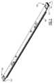
装置1000は、レリーフプレート原版に結合されるように意図された少なくとも1つの、好ましくは少なくとも2つの、さらに好ましくは少なくとも3つの搬送バー100を有する搬送システム210,220,230を備える。例えば、図1に図示するように、4つの搬送バー100を搬送システム210,220,230に提供することができる。搬送バー100は、レリーフプレート原版Pの前縁3に結合され、好ましくは、搬送バー100の端部が搬送機構に連結できるように、前縁3の全長を超えて延びる。複数のレリーフプレート原版を搬送バー100に結合することも可能であることに留意されたい。好ましくは、搬送バー100の長さは100mm~1000mmであり、より好ましくは、1000mm~4000mmである。 The
装置1000は、レリーフプレート原版Pを搬送バー100に結合するように構成されたプレート結合ステーション300と、レリーフプレート原版Pが結合された搬送バー100が処理区画400を通って移動する間にレリーフプレート原版を処理するように構成された処理区画400と、処理されたレリーフプレート原版Pを搬送バー100から切り離すように構成されたプレート切り離しステーション500とを含む。搬送システム210,220,230は、プレート結合ステーション300内のレリーフプレート原版Pに結合された後、各搬送バー100を、プレート結合ステーション300から処理ステーション400を介してプレート切り離しステーション500に、さらに、処理されたレリーフプレート原版Pから切り離された後、プレート切り離しステーション500からプレート結合ステーション300に自動的に移動させて、搬送バー100が装置1000を通して閉ループで移動するように構成される。図1に図示された実施例では、4つの搬送バー100が装置1000内を循環する。
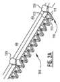
好ましい実施形態では、各搬送バー100は、複数の(ここではピンまたはロッドの形態である)貫入要素110を備え、プレート結合ステーション300は、レリーフプレート原版Pの前縁3に近い領域で複数の貫入要素110に係合するように構成される。図1において、レリーフプレート原版Pは、装置1000を通るレリーフプレート原版Pの前方搬送方向Tfに垂直な前縁3、後縁3、および前方搬送方向Tfに平行な2つの側縁1,2を有する。レリーフプレート原版Pの前縁3付近の領域は、搬送バー100の複数の貫入要素110に結合される。図2および図2Aは、搬送バー100の、より詳細な例示的な実施形態を図示する。図2Aに最もよく示されるように、複数の貫入要素1001は、好ましくは鋭い先端113を有し、プレート結合ステーション300は、好ましくは、複数の貫入要素110の少なくとも部分的に、レリーフプレート原版Pの前縁3の近くの、穿孔されていない領域に、またはそこを貫入するように構成される。しかしながら、別の例示的な実施形態によれば、図1の装置1000は、鋭利な先端を有さない複数の貫入要素110を備えた搬送バー100と共に使用されてもよいことに留意されたい。例えば、レリーフプレート原版Pの前縁3付近の領域は、レリーフプレート原版Pをプレート結合ステーション300にもたらす前に予め穿孔されてもよく、その結果、複数の貫入要素110は、前縁3付近の領域の予め穿孔された穴を通して配置されてもよい。 In a preferred embodiment, each
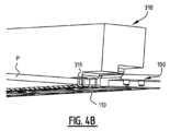
処理区画400は、入口側410および出口側420を有する。結合されたレリーフプレート原版Pを有する搬送バー100が、処理区画400を通って入口側410から出口側420に移動され、搬送バー100は前方搬送方向Tfに移動する。処理区画400の出口側420とプレート切り離しステーション500との間には、プレート排出ゾーン600が設けられている。レリーフプレート原版Pは、搬送システムによって、切り離しステーション500内の搬送バー100から切り離される前に、プレート排出ゾーン600内の処理区画400から完全に引き出される。このようにして、レリーフプレート原版Pが搬送バー100から切り離されると、レリーフプレート原版Pはプレート排出領域600に排出される。プレート排出領域600の底部には、プレート切り離しステーション500内で搬送バー100から切り離された後、処理されたレリーフプレート原版Pを取り外すように構成された取り外し手段を設けることができる。図示の実施形態では、取り外し手段700は、処理されたレリーフプレート原版Pをプレート排出領域600に受け入れ、プレート排出領域600から容易に搬送できるように、プレート排出領域から移動する為に構成されたトロリーである。例えば、装置1000がウォッシャーである場合、オペレータは、洗濯されたレリーフプレート原版を乾燥させるために、洗濯されたレリーフプレート原版Pを乾燥機に搬送することができる。他の図示しない実施形態では、取り外し手段700は、キャリア、ロボット、移動ベルト、少なくとも1つの回転ドラムなどであってもよい。また、そのような装置は、処理されたレリーフプレート原版Pがプレート切り離しステーション500内で切り離された後、プレート排出ゾーン600から移動させるように構成することもできる。
図1の実施形態において、搬送システムは、装置1000の一方の側に第1機構210を備え、装置1000の他方の側に第2搬送機構220を備えた前方搬送機構を備える。搬送機構210,220は、前方搬送方向Tfにおいて、少なくとも入口側410から処理区画400の出口側420へ、さらに、出口側420からプレート切り離しステーション500へ、結合されたレリーフプレート原版Pと共に搬送バー100を搬送するように構成される。そのために、搬送バー100の第1端101が第1前方搬送機構210に結合され、搬送バー100の第2端102が第2前方搬送機構220に結合される。図9の例示的な実施形態について図示したように、搬送システムは、搬送バー、特に搬送バーの端101および第2端102を第1搬送前方搬送機構2101および第2前方搬送機構220に結合するように構成されたバー結合手段215を備えることができる。バー結合手段215は、例えば、搬送バー100の端部101および端部102を前方搬送機構210,220に結合させるために、第1前方搬送機構および第2前方搬送機構の方向に搬送バー100を押すか又は移動させるように構成することができる。図1の実施形態において、処理区画400は、前方搬送方向Tfに延びる第1対向側面430,第2対向側面440を有し、第1前方搬送機構210および第2前方搬送機構220は、それぞれ、処理区画400の第1対向側面430および第2対向側面440に延びる。 In the embodiment of FIG. 1, the transport system comprises a forward transport mechanism with a
図9に図示するように、例示的な実施形態において、第1前方搬送機構210は、第1親ネジを備え、搬送バー100の第1端101は、第1親ネジ210に結合されるように構成された第1結合部分121を備える。同様に、第2前方搬送機構220は、第2結合部分122に結合可能な第2親ネジを備えることができる。これらの第1結合部分121および第2結合部分122は、図2にも図示されている。しかしながら、他の実施形態において、第1前方搬送機構210及び/又は第2前方搬送機構220は、チェーン又はベルトのような他の搬送手段を備えてもよく、第1結合部121及び第2結合部122は、それに応じて適合されてもよい。 As illustrated in FIG. 9 , in the exemplary embodiment, first
搬送システムは、搬送バー100をプレート切り離しステーション500からプレート結合ステーション300に搬送するように構成された後方搬送機構230をさらに備える。図1に図示された実施形態において、後方搬送機構230は、装置1000の上側に置かれる。しかしながら、他の実施形態において、後方搬送機構230は、前方搬送機構210、220の下方の装置1000の下部分に配置することができる。後方搬送機構230は、以下のいずれか一つを含むことができる。一つ又は複数のベルト、一つ又は複数のチェーン、一つ又は複数の親ネジ、リニアモータ、またはこれらの組み合わせ。 The transport system further comprises a
図1において、後方搬送機構230は、処理区画400の中央に配置される。しかしながら、後方搬送機構230は、第1前方搬送機構210、第2前方搬送機構220の上方又は下方の処理区画400の両側に配置された第1後方搬送機構及び第2後方搬送機構によって実現することもできる。あるいは、後方搬送機構は、処理区画の側方に配置されてもよく、任意に、搬送バーは、垂直位置で回転され、後方に搬送されてもよい。しかしながら、装置のフットプリントを低減するために、後方搬送機構は、好ましくは、第1前方搬送機構210及び第2前方搬送機構220の上方又は下方に置かれる。 In FIG. 1, the
図1に図示されるように、後方搬送機構230は、処理区画400の上方に一部が置かれ、搬送システムは、プレート切り離しステーション500内で切り離された搬送バー100を後方搬送機構230に向かって上方に移動させるように構成された上方搬送機構250をさらに備える。例えば、上方搬送機構250は、搬送バー100を上方向Tu、典型的には垂直方向に、前方搬送方向Tfとは反対の後方搬送方向Tbに搬送バー100を移動させる後方搬送機構230に向かって移動させ、プレート結合ステーション300に戻すことができる。上方搬送機構250は、以下のいずれか一つ又は複数を含むことができる。磁気的手段、電磁的手段、クランプ手段、真空手段、リニアモータ、チェーン、ベルト、親ネジ、ピストンまたはこれらの組み合わせ。後方搬送機構230が前方搬送機構の下方に置かれる他の実施形態では、下方搬送機構を設けることができる。下方搬送機構は、以下のいずれか一つ又は複数を備えることができる。磁気的手段、電磁的手段、クランプ手段、真空手段、リニアモータ、チェーン、ベルト、親ネジ、ピストンまたはこれらの組み合わせ、あるいは単に重力によって生じるもの。 As illustrated in FIG. 1 , the
図2および図2Aは、搬送バー100のより詳細な例示的実施形態を示す。搬送バー100は、第1端101及び第2端102に、第1結合部分121及び第2結合部分122を備えている。この場合、結合部分121は、親ネジと組み合わせて使用される結合手段と共に構成される。図2Aは、貫入要素110を有する搬送バー100の拡大図を示す。各貫入要素110は、連結部分111、貫入部分112及び先端113を有する。この場合、貫入部分112は、矩形の横断面と非対称の先端113とを有することに留意すべきである。好ましくは、貫入部分112は、貫入方向に垂直な横断面における最大寸法が5mm未満、より好ましくは、3mm未満である。すなわち、図示の矩形断面の実施例において、好ましくは、矩形の最長辺が5mm未満であり、より好ましくは、3mm未満である。搬送バー100は、ピンが搬送バー100の下から搬送バーを通過することを可能にするチャネル120を備えている(後述の図3および図3Aも参照)。 2 and 2A show a more detailed exemplary embodiment of the
次に、プレート結合ステーション300の例示的な実施形態、およびプレート結合ステーション300で行われるステップの詳細な説明を、図3、図3A、図4、および図4A-図4Cを参照して説明する。図3および図3Aは、結合ステーション300内の搬送バー100を示す。プレート結合ステーション300は、ここでは可動ピン320の形態の、搬送バー100に対してレリーフプレート前駆体Pを整列させるように構成された整列手段を備える。可動ピン320は、搬送バー100に隣接して延びている。このために、図3Aに最もよく示されるように、搬送バー100には、搬送バー100の下方から、搬送バー100を通って突出する位置まで、ピンが搬送バー100を通過することを可能にするチャネル120が設けられる。レリーフプレート原版Pを整列ピン320に対して整列させた後、整列ピン320を下方に移動させ、ハンマー工具310が、レリーフプレート原版の材料を通して複数の貫入要素110を押す(図4Aおよび図4Bを参照)。好ましい実施形態において、ハンマー工具310は、複数の貫入要素110を受け入れるように構成された複数の穴311を備える。しかしながら、他のハンマー工具310も可能であり、当業者は、一連の穴311の代わりに、例えば、複数の貫入要素110を受け入れるように構成された1つの細長い凹部を設けることも可能であることを理解する。 An exemplary embodiment of the
図5は、一つ又は複数の可動プレート180に付けられた複数の貫入要素110を備える搬送バー100の別の例示的な実施形態を図示しており、この複数の貫入要素110は、ハンマー工具(図示せず)によって押し下げられて、印刷プレート原版の材料内に少なくとも部分的に押し込まれる。貫入要素110の長さは、貫入要素110の先端113が、レリーフ原版を貫入した後、原版の下のプレートの穴に達するような長さであってもよい。このような実施形態において、ハンマー工具は平坦な下面を有することができる。さらに、一つ又は複数の可動プレート180を上方に移動させて、レリーフプレート原版を受け入れ、ハンマー工具を作動させるアクチュエータを設けてもよい。複数の貫入要素110に対して可動プレート180を有する代わりに、各貫入要素に対して旋回可能なアームを設けることができ、その後、ハンマー工具が旋回可能なアームに対して押される。 FIG. 5 illustrates another exemplary embodiment of the
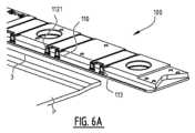
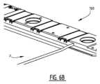
図6Aおよび図6Bは、レリーフプレート原版Pの前縁3の近くの穿孔されていない領域を貫入するように構成された複数の貫入要素110を備える搬送バー100のさらに別の実施形態を示す。この実施形態において、貫入要素110は、レリーフプレート原版の材料を通してハンマー工具によって押される鋭いナイフエッジ130を有する。このような実施形態において、ハンマー工具は、レリーフプレート原版Pの材料内で貫入要素110を下方に押す。複数の貫入要素110によって引き起こされる貫入作用は、好ましくは材料を取り外すことなく、レリーフプレート原版の材料内に穴を生成する。 6A and 6B show yet another embodiment of a
貫入要素110の形状は変化させることができ、その形状は、例えば、以下のいずれかでもよいことに留意されたい。チューブ、ブレード、ニードル、またはそれらの組み合わせ。好ましくは、各貫入要素110は、レリーフプレート原版を通って実質的に垂直に延びることを意図した貫入部分112(図2Aおよび図6Aを参照)を備え、貫入部分112は、1mm~20mmの長さを有する。さらに他の実施形態では、搬送バーに複数の貫入要素を設ける代わりに、搬送バーに鋭いエッジを有する一つ又は複数の細長いブレード要素を設けることができる。 It should be noted that the shape of the penetrating
図7Aおよび図7Bは、プレート切り離しステーション500およびプレート切り離しステーション500で実施されるステップを概略的に示す。図7Aでは、レリーフプレート原版Pは依然として搬送バー100に結合されている。レリーフプレート原版Pの下に存在する切り離しツール510は、輸送バー100が所定位置に保持されている間、上方に移動され、レリーフプレート原版Pが複数の貫入要素110から取り外される。図1を参照して上述したように、複数の貫入要素110からレリーフプレート原版Pを取り外した後、レリーフプレート原版Pは、プレート排出ゾーン600に落下し、装置1000から取り外すことができる。引き離しツール510は、単純な線形ロッドまたはバー、あるいは波形または歯状の構造を有するバーであってもよい。好ましくは、波形または歯のような構造を使用して、切り離しを容易にする。 7A and 7B schematically illustrate a
図1に示すように、装置1000は、好ましくは、搬送機構210、220,230、250などの装置の異なる構成要素を制御するように構成された制御ユニット800を備え、複数の搬送バー100のうちの1つの搬送バー100が処理区画400を通過するときに、別の搬送バーがプレート結合ステーション300に戻るようにする。より好ましくは、少なくとも3つの搬送バーがシステム内を移動する。図1において、装置1000は、プレート結合ステーション300内に1つの搬送バー、処理区画400内に1つの搬送バー、プレート切り離しステーション500内に1つの搬送バー、および後方搬送機構230によって後方に搬送される1つの搬送バーが同時に存在し得るように制御される4つの搬送バーで図示されている。好ましくは、少なくとも2つの搬送バーのうちの1つは、処理ゾーンを通って搬送され、もう1つは、結合ステーションに搬送されて戻される。また、前方搬送方向Tfの搬送速度と後方搬送方向Tbの搬送速度とが異なっていてもよく、好ましくは、後方搬送方向Tbの搬送速度が前方搬送方向Tfの搬送速度よりも速い。例えば、後方搬送方向の搬送速度を前方搬送方向の速度で割った比は、1~400、好ましくは、2~300の範囲である。典型的には、前方及び後方搬送速度は、1mm/秒~1000mm/秒の範囲である。 As shown in FIG. 1, the
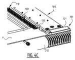
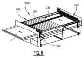
図8は、装置1000のさらに開発された例示的実施形態を図示する。処理区画400は、複数の回転ブラシ450を備える。レリーフプレート原版Pは、洗浄のためにブラシ450の下方に引っ張られる。ブラシは、それらがレリーフプレート原版Pの上にあるように配置されてもよい。さらに、ブラシ450がレリーフプレート原版上で回転する間に、レリーフプレート原版を洗浄するために、ノズルおよび液体注入手段(図示せず)が設けられてもよい。図示の実施形態において、ブラシ450は、レリーフプレート原版Pの移動方向に垂直に配置された回転軸を有する。しかしながら、他の実施形態では、少なくとも部分的に液体槽に浸漬される垂直回転軸の周りに取り付けられた多数の回転ブラシを提供することができる。回転ブラシ450または任意の代替ブラシは、レリーフプレート原版を完全に洗浄するために配置される。ブラシの回転方向は、搬送方向と同じであってもよいし、逆であってもよく、好ましくは、一部は搬送方向に回転し、一部は搬送方向と逆に回転する。さらに、ブラシをそれらの軸に対して平行な方向に移動させる(振動させる)ことができる。ブラシの速度は、広範囲の速度、例えば1rpm~約2000rpmの範囲で変化させることができる。さらに、平坦な回転ブラシまたは振動ブラシを使用することができる。被刺激性(Aggression)はまた、ブラシがプレート原版と接触する圧力および/またはブラシのプレート原版表面までの距離を制御することによって変化させることができる。ブラシは、同じであっても異なっていてもよく、また、毛の直径、剛性または硬さ、毛の密度、毛の厚さ、毛の材料(例えば、アルミニウム、ステンレス鋼、ブラジャー、ポリエチレン、ポリオキシメチレン、ポリアミド(ナイロン)、ポリエステル、またはそれらの組合せ)、毛の配置(螺旋または直線)、毛の長さおよび形状(例えば、円形、楕円形、または矩形もしくは六角形の横断面)、またはそれらの組合せにおいて変化してもよい。ブラシの被刺激性の強さ(高い被刺激性は、材料の大部分の除去に関連する)は、プロセスの開始時の高い被刺激性から、プロセスの終了時の低い被刺激性または、その逆に変化させることができる。 FIG. 8 illustrates a further developed exemplary embodiment of
使用される液体の性質は、使用される原版の性質によって導かれる。取り除かれる層が水または水溶液に可溶性、乳化性または分散性である場合、水または水溶液が、前洗浄ステーションにおいて第1液体として使用され得る。層が有機溶媒または混合物に可溶性、乳化性または分散性である場合、有機溶媒または混合物を予備洗浄ステーションにおいて第2液体として使用してもよい。原版が水系で現像可能な層を有する場合、水または主に水系の溶媒を現像ステーションで第2液体として使用することができる。有機的に現像可能な原版の場合、異なる有機溶媒またはそれらの混合物を、現像ステーションにおいて第2液体として使用してもよい。対応して、後洗浄ステーションは、第3液体として洗浄されるべきレリーフ層の性質に応じて、水、水溶液、有機溶媒、または有機溶媒の混合物を用いて操作されてもよい。 The nature of the liquid used is guided by the nature of the master used. If the layer to be removed is soluble, emulsifiable or dispersible in water or aqueous solutions, water or aqueous solutions may be used as the first liquid in the pre-washing station. If the layer is soluble, emulsifiable or dispersible in an organic solvent or mixture, the organic solvent or mixture may be used as the second liquid in the pre-wash station. If the master has an aqueous developable layer, water or a predominantly aqueous solvent can be used as the second liquid at the development station. For organically developable masters, different organic solvents or mixtures thereof may be used as the second liquid in the development station. Correspondingly, the post-washing station may operate with water, an aqueous solution, an organic solvent, or a mixture of organic solvents, depending on the nature of the relief layer to be washed as the third liquid.
液体は、水または他の成分、例えば塩、酸、塩基、乳化剤、分散助剤、粘度調整剤、界面活性剤、またはそれらの組合せを含有し得る水溶液でもよい。塩、酸および塩基を用いて、液体のpHを制御してもよい。乳化剤および分散助剤を使用して、液体の物質取り込み能力を高め、このようなエマルジョンおよび分散液を安定化させてもよい。水溶液は、有機溶媒、例えば、アルコール、エステル、エーテル、または炭化水素またはそれらの組合せを含んでもよい。 The liquid may be an aqueous solution that may contain water or other ingredients such as salts, acids, bases, emulsifiers, dispersing aids, viscosity modifiers, surfactants, or combinations thereof. Salts, acids and bases may be used to control the pH of liquids. Emulsifiers and dispersing aids may be used to enhance the material uptake capacity of liquids and to stabilize such emulsions and dispersions. The aqueous solution may contain organic solvents such as alcohols, esters, ethers, or hydrocarbons or combinations thereof.
液体は、有機溶媒またはそれらの混合物でもよい。例えば、ナフテン系または芳香族石油留分を、アルコール、例えばベンジルアルコール、シクロヘキサノール、または炭素原子数5~10の脂肪族アルコールなどのアルコールとの混合物中に含む現像液、さらに、任意に、例えば脂環式炭化水素、テルペノイド炭化水素、置換ベンゼン、例えばジイソプロピルベンゼンなどの置換ベンゼン、炭素原子数5~12のエステル、またはグリコールエーテルなどのさらなる成分を使用してもよい。適切な洗濯剤は、例えば、EP-A332 070またはEP-A433 374に開示されている。さらに、溶媒および溶媒混合物は、他の成分、例えば、塩、酸、塩基、乳化剤、分散助剤、粘度調整剤、帯電防止剤、水、界面活性剤またはそれらの組合せを含んでもよい。安全のため、および関連する装置のコストおよび複雑さを低減するために、有機溶媒を使用する際の温度は、使用される洗濯剤混合物の発火点より5℃~15℃下であるべきである。 The liquid may be an organic solvent or mixtures thereof. For example, a developer comprising a naphthenic or aromatic petroleum fraction in a mixture with an alcohol such as benzyl alcohol, cyclohexanol, or an aliphatic alcohol having from 5 to 10 carbon atoms, and optionally, for example Additional components such as cycloaliphatic hydrocarbons, terpenoid hydrocarbons, substituted benzenes such as diisopropylbenzene, esters of 5 to 12 carbon atoms, or glycol ethers may be used. Suitable washing agents are disclosed, for example, in EP-A 332 070 or EP-A 433 374. Additionally, solvents and solvent mixtures may contain other ingredients such as salts, acids, bases, emulsifiers, dispersing aids, viscosity modifiers, antistatic agents, water, surfactants, or combinations thereof. For safety and to reduce the cost and complexity of associated equipment, the temperature when using organic solvents should be 5°C to 15°C below the ignition point of the detergent mixture used. .
処理区画は、単一の液体を使用するユニットであってもよいが、同じ流体または異なる流体を使用することができる2つ以上のサブユニットから構成することもできる。また、ブラシおよびポンプ、フィルタ、トラフ、ホースなどを含む液体取り扱いシステムの配置は、共通であってもよく、またはサブユニットの数に従って分割されてもよい。 A processing compartment may be a unit using a single liquid, but may also be composed of two or more subunits that may use the same or different fluids. Also, the arrangement of the liquid handling system, including brushes and pumps, filters, troughs, hoses, etc., may be common or divided according to the number of subunits.
しかしながら、所望の処理に応じて、他の形式の処理手段を処理区画400に設けてもよい。洗濯、ブラッシング、すすぎ、スプレー、乾燥、照射、現像、加熱、冷却、材料の除去、気体または液体での処理、研磨、切断、電磁波での処理、およびこれらの組み合わせを含む群から種々の形式の処理を選択することができる。 However, other types of processing means may be provided in the
また、処理区画400内での処理は、レリーフプレート原版の液化部分を生じさせる熱処理であり、その後、液化部分を、ウェブ、不織材料、または溶融材料が付着した箔などの可動アクセプタ材料と接触させ、アクセプタ材料を用いて液化部分を連続的に除去してもよい。さらに、1つの処理区画400を有する代わりに、複数の連続する処理区画が設けられてもよい。 Also, the processing in
例えば、後処理区画を設けて、レリーフプレート原版上で後処理を行うことができ、この後処理は、洗浄、ブラッシング、すすぎ、噴霧、乾燥、照射、現像、加熱、冷却、材料の除去、気体または液体での処理、研磨、切断、電磁波での処理、およびこれらの組み合わせからなる群から選択される。後処理区画およびその構成要素は、必要に応じて条件を調整するために、制御装置によって制御されてもよい。好ましくは、後処理は、乾燥および/または電磁波による処理(後露光)を含む。 For example, a post-treatment compartment can be provided to carry out post-treatments on the relief plate master, which post-treatments include washing, brushing, rinsing, spraying, drying, irradiation, developing, heating, cooling, removing material, gassing, or selected from the group consisting of liquid treatment, polishing, cutting, electromagnetic wave treatment, and combinations thereof. The aftertreatment compartment and its components may be controlled by a controller to adjust conditions as needed. Preferably, the post-treatment includes drying and/or treatment with electromagnetic waves (post-exposure).
乾燥ステーションは、液体を完全に取り除くことを可能にする。これは、加熱、または減圧、またはその両方の組み合わせによって達成することができ、それによって、液体の蒸発が加速される。 A drying station makes it possible to completely remove the liquid. This can be accomplished by heating, or vacuum, or a combination of both, which accelerates evaporation of the liquid.
加熱は、オーブン、高温ガス(好ましくは空気または蒸気)、IR光の照射、マイクロ波の照射、またはこれらの組み合わせによって達成することができる。圧力の低減は、換気、真空ポンプ(例えば、拡散ポンプ、吸引ポンプ、オイルポンプなど)、ベンチュリ管、またはこれらの組み合わせによって達成することができる。好ましくは、IRランプまたは熱風を用いた加熱を乾燥に使用する。乾燥は、好ましくは40℃~200℃、好ましくは50℃~160℃、より好ましくは50℃~100℃、最も好ましくは50℃~80℃で行う。フレキソ印刷要素の寸法的に安定な支持体が金属支持体である場合、約160℃までの、より高い温度で乾燥を行うこともできる。 Heating can be accomplished by an oven, hot gas (preferably air or steam), IR light irradiation, microwave irradiation, or combinations thereof. Pressure reduction can be achieved by ventilation, vacuum pumps (eg, diffusion pumps, suction pumps, oil pumps, etc.), venturi tubes, or combinations thereof. Heating with an IR lamp or hot air is preferably used for drying. Drying is preferably carried out at 40°C to 200°C, preferably 50°C to 160°C, more preferably 50°C to 100°C, most preferably 50°C to 80°C. If the dimensionally stable support of the flexographic printing element is a metal support, drying can also be carried out at higher temperatures, up to about 160°C.
後露光を使用して、現像された前駆体の表面を非粘着性にし、および/または光硬化性レリーフ層をさらに硬化させることができる。このステーションにおいて、現像された原版は、好ましくはUVAまたはUVC光を用いて、電磁線で処理される。光源として、蛍光灯、LED、フラッシュランプ、またはこれらの光源のいくつかの組み合わせを使用することができる。好ましくは、LEDまたは蛍光灯が設置される。光源は、露光時間、異なる発光スペクトルを有する光源が設置される場合の波長、光強度、またはそれらの組み合わせを導く(steers)制御システムに接続することができる。 Post-exposure can be used to detackify the surface of the developed precursor and/or to further harden the photocurable relief layer. In this station the developed master is treated with electromagnetic radiation, preferably using UVA or UVC light. Fluorescent lamps, LEDs, flash lamps, or some combination of these light sources can be used as light sources. Preferably LEDs or fluorescent lights are installed. The light sources can be connected to a control system that steers the exposure time, wavelength when light sources with different emission spectra are installed, light intensity, or a combination thereof.
さらに、予備処理区画を設けて、レリーフプレート原版に対して予備処理を実施することができ、該予備処理は、切断、アブレーション、電磁放射線への曝露、およびそれらの組み合わせを含む群から選択される。また、後処理および前処理の間、印刷プレート原版は、搬送バーに結合されたままでよい。前処理区画およびその構成要素は、必要に応じて条件を調整するために、制御装置によって制御されてもよい。 Additionally, a pretreatment compartment may be provided to perform a pretreatment on the relief plate master, the pretreatment being selected from the group comprising cutting, ablation, exposure to electromagnetic radiation, and combinations thereof. . Also, the printing plate precursor may remain coupled to the carrier bar during post-processing and pre-processing. The pretreatment compartment and its components may be controlled by a controller to adjust conditions as needed.
好ましくは、前処理ステーションは、アブレーション装置、露光装置、またはその両方の組み合わせを備える。アブレーション処理は、少なくとも1つの層から材料を除去するステップを含む。例えば、画像データに応じて、少なくとも1層の材料を除去してもよい。より具体的には、処理の実施は、以下のいずれか1つを含んでもよい。電磁波への曝露;刻み込み、例えば機械的刻み込み;粒子ジェット、流体ジェット、ガスジェットのような材料ジェットへの曝露;プラズマへの曝露;熱現像のような連続ウェブへの曝露;またはこれらの組み合わせ。電磁波は、例えば、以下のいずれかである。広帯域電磁波、狭帯域電磁波、単色電磁波、例えばランプを用いた大面積電磁波、例えばレーザによって放射される選択的電磁波、ドラムの全長に沿って又はドラムの軸方向長さの一部に沿って放射される波、連続又はパルス電磁波、高エネルギ又は低エネルギ電磁波、アブレーション又は初期電磁波、UVからIR電磁波。電磁波の波長は、200~20000nmの範囲、好ましくは、250~15000nmの範囲、より好ましくは、300~11000nmの範囲、最も好ましくは、350~11000nmの範囲である。電磁放射線の全出力は、化学反応を引き起こすのに十分な低い値から、例えば、0.1mW~2000W、好ましくは、1mW~1000W、より好ましくは、5mW~7500W、最も好ましくは、1W~200Wの範囲の材料の高速加熱および蒸発またはアブレーションを引き起こす高い値までの範囲でもよい。典型的には、例えば、回転ミラーまたはドラム上でレリーフプレート原版を回転させることによって、アブレーションビームを表面上で移動させて、画像を形成する。 Preferably, the pretreatment station comprises an ablation device, an exposure device, or a combination of both. Ablation processing includes removing material from at least one layer. For example, at least one layer of material may be removed depending on the image data. More specifically, performing the process may include any one of the following. scribing, e.g., mechanical scribing; exposure to material jets, such as particle jets, fluid jets, gas jets; exposure to plasma; exposure to continuous webs, such as thermal development; combination. Electromagnetic waves are, for example, any of the following. broadband electromagnetic waves, narrowband electromagnetic waves, monochromatic electromagnetic waves, large area electromagnetic waves e.g. with lamps, selective electromagnetic waves emitted e.g. continuous or pulsed electromagnetic waves, high or low energy electromagnetic waves, ablative or incipient electromagnetic waves, UV to IR electromagnetic waves. The wavelength of the electromagnetic wave is in the range of 200-20000 nm, preferably in the range of 250-15000 nm, more preferably in the range of 300-11000 nm, most preferably in the range of 350-11000 nm. The total power of electromagnetic radiation ranges from low enough to cause chemical reactions, for example from 0.1 mW to 2000 W, preferably from 1 mW to 1000 W, more preferably from 5 mW to 7500 W, most preferably from 1 W to 200 W. It may range up to high values that cause rapid heating and vaporization or ablation of materials in the range. Typically, the ablation beam is moved over the surface to form an image, for example by rotating the relief plate master on a rotating mirror or drum.
露光装置は、レリーフ前駆体の表側または裏側に、必要な波長の光を送達する電磁放射源を含む。好ましくは、波長は、電磁スペクトルのUV-Vis領域にある。電磁波の波長は、200~800nmの範囲、好ましくは、250~500nmの範囲、より好ましくは、300~450nmの範囲、最も好ましくは、350~400nmの範囲である。電磁放射の強度は、0.1mW/cm2~200W/cm2、好ましくは、1mW/cm2~200W/cm2、より好ましくは、10mW/cm2~200W/cm2の範囲でもよい。光源として、メタルハライドランプ、蛍光ランプ、LEDまたはフラッシュランプ、またはこれらの光源のいくつかの組み合わせを使用することができる。好ましくは、LEDまたは蛍光灯が設置される。光源は、露光時間、異なる発光スペクトルを有する光源が設置される場合の波長、光強度、またはそれらの組み合わせを操作する制御システムに接続することができる。光源およびプレート原版は、露光中に静止していてもよく、または露光中に互いに相対運動していてもよい。好ましくは、プレート原版を横切って棒状LEDアレイを移動させるか、またはプレート原版をLEDアレイに通す。典型的には、露光は、プレート原版の一体部分であってもよいマスク、又は別個のマスク層、又は電子的に切り替え可能なマスク(例えば、切り替え可能な透明及び非透明の領域又はピクセルを有するディスプレイのようなデバイス)を通して行われる。マスクを使用しない走査ビームを使用することもできる。暴露区画は、周囲条件下または特定の雰囲気、例えば酸素含有量を減らした状態で使用することができる。The exposure apparatus includes an electromagnetic radiation source that delivers light of the required wavelength to the front or back side of the relief precursor. Preferably, the wavelength is in the UV-Vis region of the electromagnetic spectrum. The wavelength of the electromagnetic wave is in the range of 200-800 nm, preferably in the range of 250-500 nm, more preferably in the range of 300-450 nm, most preferably in the range of 350-400 nm. The intensity of the electromagnetic radiation may range from 0.1 mW/cm2 to 200 W/cm2 , preferably from 1 mW/cm2 to 200 W/cm2 , more preferably from 10 mW/cm2 to 200 W/cm2 . As light sources metal halide lamps, fluorescent lamps, LEDs or flash lamps, or some combination of these light sources can be used. Preferably LEDs or fluorescent lights are installed. The light sources can be connected to a control system that manipulates the exposure time, wavelength when light sources with different emission spectra are installed, light intensity, or a combination thereof. The light source and plate precursor may be stationary during exposure or may be in relative motion with each other during exposure. Preferably, the bar-shaped LED array is moved across the plate master, or the plate master is passed through the LED array. Typically, exposure involves a mask, which may be an integral part of the plate precursor, or a separate mask layer, or an electronically switchable mask (e.g., having switchable transparent and non-transparent regions or pixels). device such as a display). A scanning beam without a mask can also be used. The exposure compartment can be used under ambient conditions or in a specific atmosphere, eg with reduced oxygen content.
図9は、搬送バー100が前方搬送機構210、220に結合される位置のプレート結合ステーション300を詳細に図示する。ピストン215は、搬送バー100を親ネジの開始部に向けて押し、搬送バーを親ネジと係合させる。レリーフプレート原版Pは、図9には示されていないが、通常、図示された位置において、レリーフプレート原版Pは、複数の貫入要素110に結合されることに留意されたい。 FIG. 9 illustrates in detail the
図10は、処理区画400の上面図を図示しており、ブラシ450と、処理区画400の一側面に延在する第1前方搬送機構210とを備えている。図10は、ブラシ450の回転を駆動するための多数の結合手段455を更に図示する。 FIG. 10 illustrates a top view of
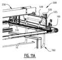
図11Aおよび図11Bおよび図11Cは、プレート切り離しステーション500の例示的な実施形態を詳細に示す。図11Aにおいて、搬送バー100は低い位置にある。この位置において、前縁3の近くで、印刷プレート原版の下面を押す引き離しツール510によって、レリーフプレート原版Pが搬送バー100の貫入要素110から切り離される。プレート引き離しステーション500は、搬送バー100を上方に引っ張るための磁石520を備えた横方向部材530を備える。空気ピストン525が設けられ、磁石520を上下させて横部材530を移動させる。次に、図11Bおよび図11Cに図示されるように、搬送バー100は、後方搬送機構230に向かって上方向Tuに移動され、印刷プレート原版は、排出ゾーン600内で落下することができる。 11A, 11B and 11C show an exemplary embodiment of
レリーフプレート原版は、一般に、第1材料から作られる支持層と、前記第1材料とは異なる第2材料から作られる追加の層とを備える。支持層は、可撓性金属、天然または人工のポリマー、紙、またはそれらの組み合わせであってもよい。好ましくは、支持層は、可撓性金属またはポリマーフィルムまたはシートである。可撓性金属の場合、支持層は、薄膜、ふるい状構造、メッシュ状構造、織布または不織布構造、またはそれらの組合せを備えることができる。鋼、銅、ニッケルまたはアルミニウムのシートが好ましく、約50~1000μmの厚さでもよい。ポリマーフィルムの場合、フィルムは寸法的に安定しているが屈曲可能であり、例えばポリアルキレン、ポリエステル、ポリエチレンテレフタレート、ポリブチレンテレフタレート、ポリアミド及びポリカーボネート、織布、不織布又は積層繊維(例えば、ガラス繊維、炭素繊維、ポリマー繊維)又はこれらの組合せで強化されたポリマーから製造することができる。好ましくは、ポリエチレンおよびポリエステルの箔が使用され、それらの厚さは、約100~300μmの範囲、好ましくは100~200μmの範囲でもよい。 A relief plate precursor generally comprises a support layer made from a first material and an additional layer made from a second material different from said first material. The support layer may be flexible metal, natural or synthetic polymer, paper, or a combination thereof. Preferably, the support layer is a flexible metal or polymer film or sheet. For flexible metals, the support layer may comprise a thin film, screen-like structure, mesh-like structure, woven or non-woven structure, or combinations thereof. Sheets of steel, copper, nickel or aluminum are preferred and may be about 50-1000 μm thick. In the case of polymeric films, the films are dimensionally stable but bendable, for example polyalkylenes, polyesters, polyethylene terephthalate, polybutylene terephthalate, polyamides and polycarbonates, wovens, nonwovens or laminated fibers (e.g. glass fibers, It can be made from polymers reinforced with carbon fibers, polymer fibers) or combinations thereof. Preferably polyethylene and polyester foils are used and their thickness may range from about 100 to 300 μm, preferably from 100 to 200 μm.
レリーフ原版は、追加の層を担持することができる。例えば、追加層は、以下のいずれかでもよい。(例えば、レーザによる)直接ヤングラヴァッレ(engravable)層、溶媒又は水で現像可能な層、熱現像可能な層、感光性層、感光性層とマスク層の組み合わせ。任意に、追加の層上に一つ又は複数の追加の層を設けてもよい。このような一つ又は複数の更なる追加層は、画像形成可能な層が画像形成される前に除去される他の全ての層の最上部にカバー層を備えてもよい。一つ又は複数の追加の層は、レリーフ層、および支持層とレリーフ層との間、または支持層のレリーフ層とは反対側にハレーション防止層を備えてもよい。一つ又は複数の追加の層は、レリーフ層、画像形成可能な層、およびレリーフ層と画像形成可能な層との間の、酸素の拡散を防止する一つ又は複数のバリア層を備えてもよい。上記の異なる層の間に、異なる層の適切な接着を確実にする一つ又は複数の接着層を置いてもよい。 The relief master can carry additional layers. For example, the additional layer may be any of the following: A direct (eg laser) engravable layer, a solvent or water developable layer, a heat developable layer, a photosensitive layer, a combination of a photosensitive layer and a mask layer. Optionally, one or more additional layers may be provided on additional layers. Such one or more additional additional layers may comprise a cover layer on top of all other layers that are removed before the imageable layer is imaged. The one or more additional layers may comprise a relief layer and an antihalation layer between the support layer and the relief layer or on the side of the support layer opposite the relief layer. The one or more additional layers may comprise a relief layer, an imageable layer, and one or more barrier layers to prevent diffusion of oxygen between the relief layer and the imageable layer. good. One or more adhesive layers may be placed between the different layers to ensure proper adhesion of the different layers.
好ましい実施形態において、レリーフプレート原版は、ポリマー材料のポリエステルからなる支持層と、レジン材料のような直接ヤングラヴァッレ材料からなる追加層とを備える。任意の層は、レーザアブレーション層であってもよい。例示的な実施形態において、レリーフプレート原版は、少なくとも寸法的に安定した支持層、レリーフ層、および画像形成可能なマスク層を含んでもよい。任意に、さらなる層が存在してもよい。画像形成可能なマスク層が画像形成される前に除去される他の全ての層の最上部にカバー層があってもよい。支持層とレリーフ層との間にハレーション防止層があってもよいし、支持層のレリーフ層とは反対側にあってもよい。レリーフ層と画像形成可能なマスク層との間には、酸素の拡散を防止する一つ又は複数のバリア層があってもよい。上記の異なる層の間に、異なる層の適切な接着を確実にする一つ又は複数の接着層を置いてもよい。一つ又は複数の層は、液体を用いた処理によって除去されてもよい。使用される液体は、異なる層に対して同一であっても異なっていてもよい。使用される液体は異なるのが好ましい。 In a preferred embodiment, the relief plate precursor comprises a support layer of polymeric material polyester and an additional layer of direct Young Lavalle material such as resin material. An optional layer may be a laser ablation layer. In an exemplary embodiment, a relief plate precursor may include at least a dimensionally stable support layer, a relief layer, and an imageable mask layer. Optionally, further layers may be present. There may be a cover layer on top of all other layers that are removed before the imageable mask layer is imaged. There may be an antihalation layer between the support layer and the relief layer or it may be on the opposite side of the support layer from the relief layer. Between the relief layer and the imageable mask layer there may be one or more barrier layers to prevent diffusion of oxygen. One or more adhesive layers may be placed between the different layers to ensure proper adhesion of the different layers. One or more layers may be removed by treatment with a liquid. The liquids used can be the same or different for the different layers. Preferably the liquids used are different.
好ましい実施形態において、レリーフプレート原版は、感光性の層およびマスク層を備える。マスク層は、処理中にアブレーションされるか又は透明度が変化されてもよく、透明及び不透明領域を有するマスクを形成する。マスクの透明領域の下で、感光性層は、照射によって溶解性および/または流動性が変化する。この変化は、一つ又は複数の後続ステップで感光層の一部を除去することによってレリーフを生成するために使用される。溶解性および/または流動性の変化は、光誘起重合および/または架橋によって達成することができ、照射領域の溶解性および溶融性を低下させる。他の場合には、電磁放射線は、結合の破壊または保護基の開裂を引き起こし、照射領域をより可溶性および/または溶融可能にする。好ましくは、光誘起架橋および/または重合を用いる方法が用いられる。 In a preferred embodiment, the relief plate precursor comprises a photosensitive layer and a mask layer. The mask layer may be ablated or changed in transparency during processing to form a mask having transparent and opaque regions. Underneath the transparent areas of the mask, the photosensitive layer changes solubility and/or flow upon irradiation. This change is used to create a relief by removing part of the photosensitive layer in one or more subsequent steps. Changes in solubility and/or flowability can be achieved by photoinduced polymerization and/or cross-linking to reduce the solubility and meltability of the irradiated areas. In other cases, the electromagnetic radiation causes bond breakage or protective group cleavage, making the irradiated area more soluble and/or meltable. Preferably, a method using photoinduced cross-linking and/or polymerization is used.
一実施形態において、可撓性プレートは、少なくとも光開始剤または光開始剤システム、バインダーおよび反応性化合物またはモノマーを備えた感光性層を備える。光開始剤は、電磁放射線の照射により、組成物の溶解度および/または溶融性の変化をもたらす重合反応、架橋反応、鎖切断または結合切断反応を開始することができる反応種を形成できる化合物である。ラジカル、酸または塩基を切断して生成する光開始剤が知られている。このような開始剤は当業者に知られており、例えば以下に記載されている。Bruce M. Monroe et al., Chemical Review, 93, 435 (1993), R. S.Davidson, Journal of Photochemistry and Biology A: Chemistry, 73, 81 (1993), J.P. Faussier, Photoinitiated Polymerization-Theory and Applications: Rapra Review,Vol. 9, Report, RapraTechnology (1998), M. Tsunooka et al., 25 Prog. Polym.Sci., 21, 1 (1996), F. D. Saeva, Topics in Current Chemistry, 1 56, 59 (1990),G. G. Maslak, Topics in Current Chemistry, 168, 1 (1993), H. B. Shuster et al.,JAGS, 112, 6329 (1990) and I. D. F. Eaton et al., JAGS, 102, 3298 (1980), P.Fouassier and J. F. Rabek, Radiation Curing in Polymer Science and Technology,pages 77 to 117 (1993) or K.K. Dietliker, Photoinitiators for free Radical andCationic Polymerisation, Chemistry & Technology of UV & EB Formulationfor Coatings, Inks and Paints, Volume, 3, Sita Technology LTD, London 1991; orR.S. Davidson, Exploring the Science, technology and Applications of U.V. andE.B. Curing, Sita Technology LTD, London 1999.その他の開始剤については、JP45-37377, JP44-86516,US3567453, US4343891, EP109772, EP109773, JP63138345, JP63142345, JP63142346,JP63143537, JP4642363, JP59152396, JP61151197, JP6341484, JP2249, JP24705,JP626223, JPB6314340, JP1559174831, JP1304453, JP1152109に記載されている。 In one embodiment, the flexible plate comprises a photosensitive layer comprising at least a photoinitiator or photoinitiator system, a binder and a reactive compound or monomer. Photoinitiators are compounds that, upon exposure to electromagnetic radiation, are capable of forming reactive species capable of initiating polymerization, cross-linking, chain scission or bond scission reactions that result in a change in solubility and/or meltability of the composition. . Photoinitiators are known which are produced by cleaving radicals, acids or bases. Such initiators are known to those skilled in the art and are described, for example, below. Bruce M. Monroe et al., Chemical Review, 93, 435 (1993), R. S. Davidson, Journal of Photochemistry and Biology A: Chemistry, 73, 81 (1993), J.P. Faussier, Photoinitiated Polymerization-Theory and Applications: Rapra Review, Vol. 9, Report, RapraTechnology (1998), M. Tsunooka et al., 25 Prog. Polym. Sci., 21, 1 (1996), F. D. Saeva, Topics in Current Chemistry, 1 56, 59 (1990), G. G. Maslak, Topics in Current Chemistry, 168, 1 (1993), H. B. Shuster et al., JAGS, 112, 6329 (1990) and I. D. F. Eaton et al., JAGS, 102, 3298 (1980), P. Fouassier and J. F. Rabek , Radiation Curing in Polymer Science and Technology,pages 77 to 117 (1993) or K.K. Dietliker, Photoinitiators for free Radical and Cationic Polymerisation, Chemistry & Technology of UV & EB Formulation for Coatings, Inks and Paints, Volume, 3, Sita Technology LTD, London 1991; orR.S. Davidson, Exploring the Science, technology and Applications of U.V. and E.B. Curing, Sita Technology LTD, London 1999. For other initiators, see JP45-37377, JP44-86516, US3567453, US4343891, EP109772. , EP109773, JP63138345, JP63142345, JP63142346,JP63143537, JP4642363, JP59152396, JP61151197, JP6341484, JP2249, JP24705,JP626223, JPB6314340, JP15 59174831, JP1304453, JP1152109.
結合剤は、直鎖、分岐または樹枝状ポリマーであるが、これらは、ホモポリマーまたはコポリマーであってもよい。コポリマーは、ランダム、交互またはブロックコポリマーでもよい。結合剤としては、水溶液、有機溶媒または両方の組み合わせのいずれかに可溶性、分散性または乳化性であるポリマーが使用される。適切なポリマーバインダーは、例えば、EP-A-0079514、EP-A-0224164またはEP-A-0059988、およびそれらの混合物に記載されているように、ポリマー類似反応によって引き続いてアクリレート化される、完全にまたは部分的に加水分解されたポリビニルエステル、例えば、部分的に加水分解されたポリ酢酸ビニル、ポリビニルアルコール誘導体、例えば、部分的に加水分解された酢酸ビニル/アルキレンオキシドグラフトコポリマー、またはポリビニルアルコールなどの、活版印刷プレートの生産に慣例的に使用されているものである。また、例えばEP-A-00856472またはDE-A-1522444に記載されているように、水または水/アルコール混合物に可溶なポリウレタンまたはポリアミドもポリマーバインダーとして適している。フレキソ印刷原版には、エラストマーバインダーが使用される。熱可塑性エラストマーブロックコポリマーは、本質的にアルケンイルアロマティクスからなる少なくとも1つのブロックと、本質的に1、3-ジエンからなる少なくとも1つのブロックとを備える。アルケンイルアロマティクスとしては、例えば、スチレン、α-メチルスチレン、ビニルトルエン等が挙げられる。スチレンが好ましい。1,3-ジエンは、好ましくはブタジエンおよび/またはイソプレンである。これらのブロックコポリマーは、線状、分枝状、または放射状ブロックコポリマーであってよい。一般に、それらは、A-B-A型のトリブロックコポリマーであるが、それらはまた、A-B型のジブロックポリマーであってもよく、または複数の交互のエラストマーおよび熱可塑性ブロックを有するポリマーであってもよい。たとえば、A-B-A-B-Aである。2種以上の異なるブロックコポリマーの混合物を使用することもできる。市販のトリブロックコポリマーは、しばしばジブロックコポリマーの特定の画分(fractions)を含む。ジエン単位は1,2-または1,4-結合でもよい。さらに、使用することができるのは、スチレンおよびブロックとの熱可塑性エラストマーブロックコポリマー、およびランダムスチレン-ブタジエン中間ブロックである。もちろん、レリーフ形成層の特性が結果として悪影響を受けない限り、2種以上の熱可塑性エラストマーバインダーの混合物を使用することもできる。上述の熱可塑性-エラストマーブロックコポリマーと同様に、光重合性層は、ブロックコポリマー以外のエラストマーバインダーをさらに含んでもよい。二次バインダーとも呼ばれるこの種の追加バインダーを用いて、光重合性層の特性を変更することができる。第二のバインダーの実施例は、ビニルトルエン-α-メチルスチレンコポリマーである。これらのポリマーバインダーは、一般に、層の全量の20~98重量%、好ましくは50~9050重量%を占める。 Binders are linear, branched or dendritic polymers, but they may be homopolymers or copolymers. Copolymers may be random, alternating or block copolymers. As binders, polymers are used that are soluble, dispersible or emulsifiable in either aqueous solutions, organic solvents or a combination of both. Suitable polymeric binders are, for example, complete binders which are subsequently acrylated by polymer-analogous reactions, as described in EP-A-0079514, EP-A-0224164 or EP-A-0059988, and mixtures thereof. partially hydrolyzed polyvinyl esters, such as partially hydrolyzed polyvinyl acetate, polyvinyl alcohol derivatives, such as partially hydrolyzed vinyl acetate/alkylene oxide graft copolymers, or polyvinyl alcohol, etc. , which is customarily used in the production of letterpress printing plates. Also suitable as polymeric binders are polyurethanes or polyamides which are soluble in water or water/alcohol mixtures, as described for example in EP-A-00856472 or DE-A-1522444. Elastomeric binders are used in flexographic printing original plates. The thermoplastic elastomer block copolymer comprises at least one block consisting essentially of alkenylaromatics and at least one block consisting essentially of 1,3-diene. Alkeneylaromatics include, for example, styrene, α-methylstyrene, vinyltoluene, and the like. Styrene is preferred. The 1,3-diene is preferably butadiene and/or isoprene. These block copolymers may be linear, branched or radial block copolymers. Generally they are triblock copolymers of type A-B-A, but they may also be di-block polymers of type A-B, or polymers having multiple alternating elastomeric and thermoplastic blocks. may be For example, A-B-A-B-A. Mixtures of two or more different block copolymers can also be used. Commercially available triblock copolymers often contain specific fractions of diblock copolymers. The diene units may be 1,2- or 1,4-linked. Also usable are thermoplastic elastomer block copolymers with styrene and blocks, and random styrene-butadiene midblocks. Of course, mixtures of two or more thermoplastic elastomer binders can be used as long as the properties of the relief-forming layer are not adversely affected as a result. As with the thermoplastic-elastomeric block copolymers described above, the photopolymerizable layer may further comprise an elastomeric binder other than the block copolymer. Additional binders of this type, also called secondary binders, can be used to modify the properties of the photopolymerizable layer. An example of a second binder is vinyltoluene-α-methylstyrene copolymer. These polymeric binders generally constitute 20 to 98% by weight, preferably 50 to 9050% by weight of the total amount of the layer.
混合物の調製に適した反応性化合物またはモノマーは、重合性であり、バインダーと相溶性のものである。この形式の有用なモノマーは一般に100℃以上の沸点を有する。それらは通常3000未満、好ましくは2000未満の分子量を有する。使用されるエチレン性不飽和モノマーは、結合剤と相溶性であるべきであり、それらは少なくとも1つの重合可能なエチレン性不飽和基を有する。モノマーとしては、特に、アクリル酸またはメタクリル酸と、一官能性または多官能性アルコール、アミン、アミノアルコールまたはハイドロクイエスエスおよびヒドロキシエステル、フマル酸またはマレイン酸のエステル、およびアリル化合物とのエステルまたはアミドを使用することができる。アクリル酸またはメタクリル酸のエステルが好ましい。1,4-ブタンジオールジアクリレート、1,6-ヘキサンジオールジアクリレート、1,6-ヘキサンジオールジメタクリレート、1,9-ノナナディールジアクリレート又はトリメチロールプロパントリアクリレートが好ましい。もちろん、異なるモノマーの混合物を使用することができる。レリーフ形成層に併用される全モノマーの総量は、レリーフ形成層の全成分の合計に対して、通常1~20重量%、好ましくは5~20重量%である。2個のエチレン性不飽和基を有するモノマーの量は、レリーフ形成層の全成分の合計に対して、好ましくは5~20重量%、より好ましくは8~18重量%である。 Reactive compounds or monomers suitable for preparing the mixture are polymerizable and compatible with the binder. Useful monomers of this type generally have boiling points above 100°C. They usually have a molecular weight of less than 3000, preferably less than 2000. The ethylenically unsaturated monomers used should be compatible with the binder and they have at least one polymerizable ethylenically unsaturated group. Monomers include, in particular, esters or amides of acrylic or methacrylic acid with mono- or polyfunctional alcohols, amines, aminoalcohols or hydroqueries and hydroxy esters, esters of fumaric acid or maleic acid and allyl compounds. can be used. Esters of acrylic acid or methacrylic acid are preferred. 1,4-butanediol diacrylate, 1,6-hexanediol diacrylate, 1,6-hexanediol dimethacrylate, 1,9-nonanadir diacrylate or trimethylolpropane triacrylate are preferred. Of course, mixtures of different monomers can be used. The total amount of all monomers used together in the relief-forming layer is generally 1-20% by weight, preferably 5-20% by weight, based on the total of all components of the relief-forming layer. The amount of the monomer having two ethylenically unsaturated groups is preferably 5-20% by weight, more preferably 8-18% by weight, based on the total of all components of the relief-forming layer.
感光層は、さらなる成分を備えてもよい。さらなる成分は、さらなるポリマー、充填剤、可塑剤、抗ブロッキング剤、モノマー、添加剤(例えば、安定化剤、色素)、安定化剤、架橋剤、結合剤、発色化合物、色素、顔料、酸化防止剤、およびこれらの組み合わせからなる群から選択される。 The photosensitive layer may comprise further components. Further components are further polymers, fillers, plasticizers, antiblocking agents, monomers, additives (e.g. stabilizers, pigments), stabilizers, crosslinkers, binders, color-forming compounds, pigments, pigments, antioxidants. agents, and combinations thereof.
別の実施形態において、可撓性プレートは、上述の感光性層とマスク層とを備え、マスク層は、少なくとも、電磁放射線を吸収することができる化合物と、(デジタルプレート原版としても知られる)アブレーションによって除去することができる成分とを備える。好ましくは、マスク層は、レリーフ原版の一体層であり、感光層または感光層とマスク層との間に配置された機能層と直接接触している。この機能層は、好ましくはバリア層であり、酸素を遮断する。マスク層は、アブレーションによって画像形成することができ、溶媒または熱現像によって除去することができる。マスク層は、高エネルギ電磁放射線の照射によって加熱され、除去され、それによって、画像のように構造化されたマスクが形成され、これを用いて、構造がレリーフ原版上に転写される。そうするために、マスク層は、UV領域では不透明であり、電磁スペクトルのVIS-IR領域の放射線を吸収する。次いで、VIS-IR放射を使用して、層を加熱および除去することができる。330~420nmのUV領域におけるマスク層の光学濃度は、1~5の範囲、好ましくは1.5~4の範囲、より好ましくは2~4の範囲である。 In another embodiment, the flexible plate comprises a photosensitive layer as described above and a masking layer, the masking layer comprising at least a compound capable of absorbing electromagnetic radiation (also known as a digital plate master). and a component that can be removed by ablation. Preferably, the masking layer is an integral layer of the relief master and is in direct contact with the photosensitive layer or a functional layer arranged between the photosensitive layer and the masking layer. This functional layer is preferably a barrier layer and blocks oxygen. The mask layer can be imaged by ablation and removed by solvent or thermal development. The masking layer is heated by exposure to high-energy electromagnetic radiation and removed, thereby forming an image-wise structured mask with which the structure is transferred onto the relief master. To do so, the mask layer is opaque in the UV region and absorbs radiation in the VIS-IR region of the electromagnetic spectrum. VIS-IR radiation can then be used to heat and remove the layer. The optical density of the mask layer in the 330-420 nm UV region is in the range 1-5, preferably in the range 1.5-4, more preferably in the range 2-4.
アラタブルマスク層の層厚は、0.1~5μm、好ましくは、0.3~4μm、より好ましくは、1~3mmの範囲である。(1cm2を除去するのに必要なエネルギとして測定される)マスク層のレーザ感度は、0.1~10mJ/cm2の範囲、好ましくは0.3~5mJ/cm2の範囲、最も好ましくは、0.5~5mJ/cm2の範囲である。The layer thickness of the adjustable mask layer is in the range of 0.1-5 μm, preferably 0.3-4 μm, more preferably 1-3 mm. The laser sensitivity of the mask layer (measured as the energy required to remove 1 cm2 ) is in the range 0.1-10 mJ/cm2 , preferably in the range 0.3-5 mJ/cm2 , most preferably , in the range of 0.5 to 5 mJ/cm2 .
本発明の原理は、特定の実施形態に関連して上述したが、この説明は、例示のためにのみなされたものであり、添付の特許請求の範囲によって決定される保護範囲の限定としてはなされていないことを理解されたい。 Although the principles of the present invention have been described above in connection with particular embodiments, this description is made by way of example only and not as a limitation of the scope of protection determined by the appended claims. It should be understood that no
Claims (33)
Translated fromJapanese少なくとも1つの貫入要素を備える搬送バー(100)と、
前記少なくとも1つの貫入要素(110)が、前記レリーフプレート原版の縁部付近の非穿孔領域を貫入することによって、前記レリーフプレート原版を前記搬送バー(100)に結合するように構成されたプレート結合ステーション(300)と、
を備え、
前記プレート結合ステーション(300)は、レリーフプレート原版を前記搬送バー(100)に対して整列させるように構成された整列手段(320)を備え、前記整列手段(320)は、整列位置で前記搬送バー(100)を貫入して突出し、静止位置で前記搬送バー(100)から離れるように移動する可動要素を備える、装置(1000)。In an apparatus (1000) for processing a relief plate master, such as a printing plate master (P) to be processed,
a carrier bar (100) comprising at least one penetrating element;
A plate coupling, wherein said at least one penetrating element(110) is configured to couple said relief plate master to said carrier bar (100) by penetrating a non-perforated area near an edge of said relief plate master. a station (300);
with
Said plate binding station (300) comprises alignment means (320) configured to align a relief plate master with respect to said transport bar (100), said alignment means (320) being adapted to transport said transport in an aligned position. A device (1000) comprising a movable element that penetrates and protrudes a bar (100) and moves away from said carrier bar (100) in a rest position.
少なくとも1つの貫入要素(110)を有する搬送バー(100)を提供するステップと、
前記レリーフプレート原版が前記搬送バーに結合されるように、前記レリーフプレート原版の縁部付近の非穿孔領域を通して前記少なくとも1つの貫入要素(110)を貫入させるステップと、
整列手段(320)により前記搬送バー(100)に対して前記レリーフプレート原版を整列させるステップであって、前記整列手段(320)は、整列位置で前記搬送バー(100)を貫入して突出し、静止位置で前記搬送バー(100)から離れるように移動する可動要素を備える、ステップと、
を含む、方法。In the method for conveying the original relief plate (P),
providing a carrier bar (100) having at least one penetrating element (110);
penetrating the at least one penetrating element (110) through a non-perforated area near the edge of the original relief plate such that the original relief plate is coupled to the carrier bar;
a step of aligning the original relief plate with respect to the carrier bar (100) by an alignment means (320), wherein the alignment means (320) penetrates and protrudes through the carrier bar (100) at an alignment position; comprising a movable element that moves away from said carrier bar (100) in a rest position;
A method, including
Applications Claiming Priority (5)
| Application Number | Priority Date | Filing Date | Title |
|---|---|---|---|
| NL2020836ANL2020836B1 (en) | 2018-04-26 | 2018-04-26 | Apparatus and method for treating a relief plate precursor |
| NL2020836 | 2018-04-26 | ||
| NL2020835ANL2020835B1 (en) | 2018-04-26 | 2018-04-26 | Apparatus and method for treating a relief plate precursor |
| NL2020835 | 2018-04-26 | ||
| PCT/EP2019/060365WO2019206906A1 (en) | 2018-04-26 | 2019-04-23 | Apparatus and method for treating and transporting a relief printing plate precursor |
Publications (2)
| Publication Number | Publication Date |
|---|---|
| JP2021522536A JP2021522536A (en) | 2021-08-30 |
| JP7326660B2true JP7326660B2 (en) | 2023-08-16 |
Family
ID=66349510
Family Applications (3)
| Application Number | Title | Priority Date | Filing Date |
|---|---|---|---|
| JP2020557933AActiveJP7326660B2 (en) | 2018-04-26 | 2019-04-23 | Apparatus and method for processing relief plate precursor |
| JP2020557941AActiveJP7500432B2 (en) | 2018-04-26 | 2019-04-23 | Apparatus and method for processing a relief plate master - Patent application |
| JP2023204009AActiveJP7692462B2 (en) | 2018-04-26 | 2023-12-01 | Apparatus and method for processing a relief plate master - Patent application |
Family Applications After (2)
| Application Number | Title | Priority Date | Filing Date |
|---|---|---|---|
| JP2020557941AActiveJP7500432B2 (en) | 2018-04-26 | 2019-04-23 | Apparatus and method for processing a relief plate master - Patent application |
| JP2023204009AActiveJP7692462B2 (en) | 2018-04-26 | 2023-12-01 | Apparatus and method for processing a relief plate master - Patent application |
Country Status (5)
| Country | Link |
|---|---|
| US (3) | US11953834B2 (en) |
| EP (3) | EP3784494B1 (en) |
| JP (3) | JP7326660B2 (en) |
| CN (2) | CN112672883B (en) |
| WO (2) | WO2019206911A1 (en) |
Families Citing this family (9)
| Publication number | Priority date | Publication date | Assignee | Title |
|---|---|---|---|---|
| JP7326660B2 (en)* | 2018-04-26 | 2023-08-16 | エクシス プリプレス エヌ.ブイ. | Apparatus and method for processing relief plate precursor |
| NL2023988B1 (en) | 2019-10-10 | 2021-04-15 | Xeikon Prepress Nv | Punching Station and Method for a Relief plate precursor |
| NL2025238B1 (en) | 2020-03-30 | 2021-10-22 | Xeikon Prepress Nv | Apparatus and method for treating a relief plate precursor with improved liquid evacuation |
| NL2025512B1 (en)* | 2020-05-06 | 2021-11-23 | Xeikon Prepress Nv | Apparatus and method for treating a relief precursor with reduced cleaning |
| NL2025875B1 (en) | 2020-06-19 | 2022-02-17 | Xeikon Prepress Nv | Apparatus and method for exposure of relief precursors |
| NL2027143B1 (en)* | 2020-12-17 | 2022-07-11 | Xeikon Prepress Nv | Apparatus and methods for manipulating plates |
| EP4263402B1 (en) | 2020-12-17 | 2025-02-12 | XSYS Prepress NV | Apparatus and methods for manipulating plates |
| NL2028683B1 (en)* | 2021-07-09 | 2023-01-16 | Xeikon Prepress Nv | Apparatus and methods for manipulating plates |
| NL2028000B1 (en)* | 2021-04-16 | 2022-10-31 | Xeikon Prepress Nv | Apparatus and methods for manipulating plates |
Citations (1)
| Publication number | Priority date | Publication date | Assignee | Title |
|---|---|---|---|---|
| JP2012063774A (en) | 2010-09-17 | 2012-03-29 | E I Du Pont De Nemours & Co | Method and device for fixing printing plate to mountable surface |
Family Cites Families (56)
| Publication number | Priority date | Publication date | Assignee | Title |
|---|---|---|---|---|
| US3102632A (en)* | 1959-07-16 | 1963-09-03 | Samuel M Langston Co | Edge piercing means and blank conveying means |
| DE1572136B1 (en) | 1965-06-03 | 1969-09-18 | Du Pont | Photopolymerizable mixture |
| DE1522444B2 (en) | 1967-03-10 | 1977-07-07 | Basf Ag, 6700 Ludwigshafen | POLYMERIZATION INHIBITOR CONTAINING LIGHT-NETWORKABLE MIXTURE |
| US3567453A (en) | 1967-12-26 | 1971-03-02 | Eastman Kodak Co | Light sensitive compositions for photoresists and lithography |
| CA933792A (en) | 1968-10-09 | 1973-09-18 | W. Heseltine Donald | Photopolymerization |
| DE2909992A1 (en) | 1979-03-14 | 1980-10-02 | Basf Ag | PHOTOPOLYMERIZABLE RECORDING MEASURES, IN PARTICULAR FOR THE PRODUCTION OF PRINTING PLATES AND RELIEF FORMS |
| US4343891A (en) | 1980-05-23 | 1982-08-10 | Minnesota Mining And Manufacturing Company | Fixing of tetra (hydrocarbyl) borate salt imaging systems |
| JPS5753747A (en) | 1980-09-17 | 1982-03-30 | Fuji Photo Film Co Ltd | Photopolymerizing composition |
| DE3144905A1 (en) | 1981-11-12 | 1983-05-19 | Basf Ag, 6700 Ludwigshafen | LIGHT-SENSITIVE LABELING MATERIAL SUITABLE FOR PRODUCING PRINT AND RELIEF FORMS AND METHOD FOR THE PRODUCTION OF PRINTING AND RELIEF FORMS BY THIS RECORDING MATERIAL |
| JPS5954561A (en)* | 1982-09-24 | 1984-03-29 | Seihachirou Shimamura | Method and apparatus for continuous letterpress printing |
| US4450227A (en) | 1982-10-25 | 1984-05-22 | Minnesota Mining And Manufacturing Company | Dispersed imaging systems with tetra (hydrocarbyl) borate salts |
| US4447521A (en) | 1982-10-25 | 1984-05-08 | Minnesota Mining And Manufacturing Company | Fixing of tetra(hydrocarbyl)borate salt imaging systems |
| JPS59112213A (en) | 1982-12-20 | 1984-06-28 | Mitsutoyo Mfg Co Ltd | Optical measuring device |
| US4590287A (en) | 1983-02-11 | 1986-05-20 | Ciba-Geigy Corporation | Fluorinated titanocenes and photopolymerizable composition containing same |
| JPS59174831A (en) | 1983-03-24 | 1984-10-03 | Fuji Photo Film Co Ltd | Photopolymerizable composition |
| US4713401A (en) | 1984-12-20 | 1987-12-15 | Martin Riediker | Titanocenes and a radiation-polymerizable composition containing these titanocenes |
| JPS626223A (en) | 1985-07-02 | 1987-01-13 | Matsushita Electric Ind Co Ltd | ferroelectric liquid crystal panel |
| DE3541162A1 (en) | 1985-11-21 | 1987-05-27 | Basf Ag | PHOTO-SENSITIVE RECORDING MATERIALS WITH ELASTOMERIC GRAFT COPOLYMERISAT BINDERS AND RELIEVE THEREOF |
| NL8503402A (en)* | 1985-12-10 | 1986-08-01 | Anderson & Vreeland Bv | Apparatus for treating printing plates with a liquid |
| JPS62236743A (en) | 1986-04-08 | 1987-10-16 | Tomiya Yoshimatsu | Method and apparatus for supplying printing plate to printing plate washing apparatus |
| US4743531A (en) | 1986-11-21 | 1988-05-10 | Eastman Kodak Company | Dye sensitized photographic imaging system |
| US4743528A (en) | 1986-11-21 | 1988-05-10 | Eastman Kodak Company | Enhanced imaging composition containing an azinium activator |
| US4743529A (en) | 1986-11-21 | 1988-05-10 | Eastman Kodak Company | Negative working photoresists responsive to shorter visible wavelengths and novel coated articles |
| US4743530A (en) | 1986-11-21 | 1988-05-10 | Eastman Kodak Company | Negative working photoresists responsive to longer wavelengths and novel coated articles |
| US5026625A (en) | 1987-12-01 | 1991-06-25 | Ciba-Geigy Corporation | Titanocenes, the use thereof, and n-substituted fluoroanilines |
| DE3807929A1 (en) | 1988-03-10 | 1989-09-28 | Basf Ag | METHOD FOR THE PRODUCTION OF RELEASE STANDARDS |
| EP0334338A3 (en) | 1988-03-24 | 1990-06-20 | Dentsply International, Inc. | Titanate initiators for light cured compositions |
| JPH01261196A (en)* | 1988-04-12 | 1989-10-18 | Muneharu Nakamura | Conveyance device for printing plates, etc. |
| JP2757375B2 (en) | 1988-06-02 | 1998-05-25 | 東洋紡績株式会社 | Photopolymerizable composition |
| JP2566326B2 (en) | 1988-08-23 | 1996-12-25 | イー・アイ・デュポン・ドゥ・ヌムール・アンド・カンパニー | How to make a printed relief for a flexograph |
| JPH0580537A (en) | 1991-09-19 | 1993-04-02 | Toyobo Co Ltd | Photosensitive resin plate carrier device |
| DE4231102C2 (en)* | 1992-09-17 | 1998-07-02 | Du Pont Deutschland | Process for the production of photopolymerizable flexographic printing plates |
| DE4231103C2 (en) | 1992-09-17 | 1995-06-29 | Du Pont Deutschland | Method for transporting a flexographic printing plate through a processing device and device for producing flexographic printing plates |
| US5819661A (en)* | 1995-01-23 | 1998-10-13 | Presstek, Inc. | Method and apparatus for laser imaging of lithographic printing members by thermal non-ablative transfer |
| JP2962686B2 (en)* | 1997-02-07 | 1999-10-12 | 株式会社金田機械製作所 | Plate making equipment for newspaper printing |
| JPH1152109A (en) | 1997-07-31 | 1999-02-26 | Jiomatetsuku Kk | Production of color synthesizer |
| JP2003170571A (en)* | 2001-12-10 | 2003-06-17 | Pioneer Electronic Corp | Mask washing apparatus |
| JP2003287899A (en)* | 2002-03-28 | 2003-10-10 | Dainippon Screen Mfg Co Ltd | Machine plate supply arrangement |
| JP4642363B2 (en) | 2004-03-08 | 2011-03-02 | 株式会社三共 | Gaming system and gaming machine |
| JP4486516B2 (en) | 2004-05-21 | 2010-06-23 | 新日本製鐵株式会社 | ERW steel pipe excellent in cold workability and hardenability and its manufacturing method |
| ATE402012T1 (en)* | 2005-09-27 | 2008-08-15 | Agfa Graphics Nv | METHOD FOR PRODUCING A LITHOGRAPHIC PRINTING PLATE |
| EP1997627A1 (en)* | 2007-06-01 | 2008-12-03 | Andromeda S.r.l. | Image forming device, in particular for printing litographic plates |
| JP2008307812A (en)* | 2007-06-15 | 2008-12-25 | Asahi Kasei Chemicals Corp | Plate holder |
| JP2009255491A (en)* | 2008-04-15 | 2009-11-05 | Matsumoto Tekkosho:Kk | Washing device for printing die |
| CN102285269A (en)* | 2011-05-25 | 2011-12-21 | 乐凯华光印刷科技有限公司 | Photopolymerization type lithographic plate main body |
| ES2588075T3 (en)* | 2013-01-11 | 2016-10-28 | Agfa Graphics Nv | Method of manufacturing a lithographic printing plate |
| JP2014184998A (en)* | 2013-03-22 | 2014-10-02 | Dainippon Screen Mfg Co Ltd | Method and device for transfer of plate-like conveyed object, and pattern forming apparatus |
| WO2015044437A1 (en)* | 2013-09-30 | 2015-04-02 | Flint Group Germany Gmbh | Device and method for the in-line production of flexographic printing plates |
| JP6341484B2 (en) | 2013-11-05 | 2018-06-13 | 株式会社 資生堂 | Cosmetic application container |
| US9618847B2 (en)* | 2014-02-20 | 2017-04-11 | E I Du Pont De Nemours And Company | Composite printing form precursor and method for preparing a printing form precursor for treatment |
| JP6314340B2 (en) | 2014-03-26 | 2018-04-25 | 松谷化学工業株式会社 | Method for producing indigestible dextrin |
| CN106457816A (en)* | 2014-07-02 | 2017-02-22 | 富士胶片株式会社 | Lithographic printing plate processing device, plate-making system for lithographic printing plates, lithographic printing plate, processing method for lithographic printing plates, and printing method |
| WO2016030450A1 (en)* | 2014-08-28 | 2016-03-03 | Flint Group Germany Gmbh | Apparatus and method for producing flexographic printing plates |
| US10668711B2 (en)* | 2015-06-02 | 2020-06-02 | E I Du Pont De Nemours And Company | Printing form precursor, a process for making the precursor, and a method for preparing a printing form from the precursor |
| IT201700051285A1 (en)* | 2017-05-11 | 2018-11-11 | Sasu Vianord Eng | POWER SUPPLY UNIT FOR AUTOMATIC LOADING OF A FLEXOGRAPHIC SLAB IN A TREATMENT STATION |
| JP7326660B2 (en)* | 2018-04-26 | 2023-08-16 | エクシス プリプレス エヌ.ブイ. | Apparatus and method for processing relief plate precursor |
- 2019
- 2019-04-23JPJP2020557933Apatent/JP7326660B2/enactiveActive
- 2019-04-23EPEP19720812.7Apatent/EP3784494B1/enactiveActive
- 2019-04-23WOPCT/EP2019/060370patent/WO2019206911A1/ennot_activeCeased
- 2019-04-23WOPCT/EP2019/060365patent/WO2019206906A1/ennot_activeCeased
- 2019-04-23CNCN201980043887.3Apatent/CN112672883B/enactiveActive
- 2019-04-23JPJP2020557941Apatent/JP7500432B2/enactiveActive
- 2019-04-23USUS17/050,076patent/US11953834B2/enactiveActive
- 2019-04-23USUS17/050,112patent/US12078932B2/enactiveActive
- 2019-04-23EPEP19720811.9Apatent/EP3784493B1/enactiveActive
- 2019-04-23CNCN201980043892.4Apatent/CN112512811A/enactivePending
- 2019-04-23EPEP25191806.6Apatent/EP4614232A2/enactivePending
- 2023
- 2023-10-13USUS18/486,754patent/US20240036472A1/enactivePending
- 2023-12-01JPJP2023204009Apatent/JP7692462B2/enactiveActive
Patent Citations (1)
| Publication number | Priority date | Publication date | Assignee | Title |
|---|---|---|---|---|
| JP2012063774A (en) | 2010-09-17 | 2012-03-29 | E I Du Pont De Nemours & Co | Method and device for fixing printing plate to mountable surface |
Also Published As
| Publication number | Publication date |
|---|---|
| US20240036472A1 (en) | 2024-02-01 |
| JP7692462B2 (en) | 2025-06-13 |
| JP2024028822A (en) | 2024-03-05 |
| EP3784493A1 (en) | 2021-03-03 |
| US11953834B2 (en) | 2024-04-09 |
| CN112672883B (en) | 2023-04-18 |
| EP3784493B1 (en) | 2025-08-20 |
| US20210362530A1 (en) | 2021-11-25 |
| EP3784494B1 (en) | 2025-08-20 |
| WO2019206911A1 (en) | 2019-10-31 |
| JP2021522536A (en) | 2021-08-30 |
| US12078932B2 (en) | 2024-09-03 |
| EP3784494A1 (en) | 2021-03-03 |
| CN112512811A (en) | 2021-03-16 |
| JP2021522129A (en) | 2021-08-30 |
| EP4614232A2 (en) | 2025-09-10 |
| CN112672883A (en) | 2021-04-16 |
| JP7500432B2 (en) | 2024-06-17 |
| WO2019206906A1 (en) | 2019-10-31 |
| US20210362484A1 (en) | 2021-11-25 |
Similar Documents
| Publication | Publication Date | Title |
|---|---|---|
| JP7326660B2 (en) | Apparatus and method for processing relief plate precursor | |
| US12076974B2 (en) | Method for identifying a relief precursor for producing a relief structure | |
| CN111433681B (en) | Apparatus and method for developing printing precursors | |
| CN110955121B (en) | Method for thermally developing relief precursors | |
| NL2020835B1 (en) | Apparatus and method for treating a relief plate precursor | |
| NL2020836B1 (en) | Apparatus and method for treating a relief plate precursor | |
| JP7657236B2 (en) | Apparatus and method for processing a relief master with improved liquid drainage - Patents.com | |
| US12393120B2 (en) | Apparatus and method for treating a relief precursor with reduced cleaning | |
| CN114126774B (en) | Apparatus and method for treating relief printing plate precursors with liquids | |
| CN114728432B (en) | Punching station and punching method for relief printing plate precursor | |
| WO2023001628A1 (en) | Apparatus and method for treating a relief precursor with liquid |
Legal Events
| Date | Code | Title | Description |
|---|---|---|---|
| A621 | Written request for application examination | Free format text:JAPANESE INTERMEDIATE CODE: A621 Effective date:20220304 | |
| A977 | Report on retrieval | Free format text:JAPANESE INTERMEDIATE CODE: A971007 Effective date:20230130 | |
| A131 | Notification of reasons for refusal | Free format text:JAPANESE INTERMEDIATE CODE: A131 Effective date:20230221 | |
| A521 | Request for written amendment filed | Free format text:JAPANESE INTERMEDIATE CODE: A523 Effective date:20230512 | |
| TRDD | Decision of grant or rejection written | ||
| A01 | Written decision to grant a patent or to grant a registration (utility model) | Free format text:JAPANESE INTERMEDIATE CODE: A01 Effective date:20230704 | |
| A61 | First payment of annual fees (during grant procedure) | Free format text:JAPANESE INTERMEDIATE CODE: A61 Effective date:20230707 | |
| R150 | Certificate of patent or registration of utility model | Ref document number:7326660 Country of ref document:JP Free format text:JAPANESE INTERMEDIATE CODE: R150 |