JP7324766B2 - Pump device for dosing flowable products - Google Patents
Pump device for dosing flowable productsDownload PDFInfo
- Publication number
- JP7324766B2 JP7324766B2JP2020552243AJP2020552243AJP7324766B2JP 7324766 B2JP7324766 B2JP 7324766B2JP 2020552243 AJP2020552243 AJP 2020552243AJP 2020552243 AJP2020552243 AJP 2020552243AJP 7324766 B2JP7324766 B2JP 7324766B2
- Authority
- JP
- Japan
- Prior art keywords
- product
- fluent
- stator
- dispensing
- flexible tube
- Prior art date
- Legal status (The legal status is an assumption and is not a legal conclusion. Google has not performed a legal analysis and makes no representation as to the accuracy of the status listed.)
- Active
Links
- 230000009969flowable effectEffects0.000titleclaimsdescription6
- 238000005086pumpingMethods0.000claimsdescription52
- 230000002572peristaltic effectEffects0.000claimsdescription46
- 239000007788liquidSubstances0.000description13
- 239000000463materialSubstances0.000description7
- 239000004033plasticSubstances0.000description5
- 229920003023plasticPolymers0.000description5
- 230000000295complement effectEffects0.000description4
- 238000004519manufacturing processMethods0.000description4
- 239000012858resilient materialSubstances0.000description4
- 235000013361beverageNutrition0.000description3
- 229920000915polyvinyl chloridePolymers0.000description2
- 239000004800polyvinyl chlorideSubstances0.000description2
- 238000011109contaminationMethods0.000description1
- 239000012530fluidSubstances0.000description1
- 239000004615ingredientSubstances0.000description1
- 238000002347injectionMethods0.000description1
- 239000007924injectionSubstances0.000description1
- 238000001990intravenous administrationMethods0.000description1
- 238000012986modificationMethods0.000description1
- 230000004048modificationEffects0.000description1
Images


Classifications
- F—MECHANICAL ENGINEERING; LIGHTING; HEATING; WEAPONS; BLASTING
- F04—POSITIVE - DISPLACEMENT MACHINES FOR LIQUIDS; PUMPS FOR LIQUIDS OR ELASTIC FLUIDS
- F04B—POSITIVE-DISPLACEMENT MACHINES FOR LIQUIDS; PUMPS
- F04B43/00—Machines, pumps, or pumping installations having flexible working members
- F04B43/12—Machines, pumps, or pumping installations having flexible working members having peristaltic action
- F04B43/1253—Machines, pumps, or pumping installations having flexible working members having peristaltic action by using two or more rollers as squeezing elements, the rollers moving on an arc of a circle during squeezing
- F04B43/1292—Pumps specially adapted for several tubular flexible members
- F—MECHANICAL ENGINEERING; LIGHTING; HEATING; WEAPONS; BLASTING
- F04—POSITIVE - DISPLACEMENT MACHINES FOR LIQUIDS; PUMPS FOR LIQUIDS OR ELASTIC FLUIDS
- F04B—POSITIVE-DISPLACEMENT MACHINES FOR LIQUIDS; PUMPS
- F04B43/00—Machines, pumps, or pumping installations having flexible working members
- F04B43/12—Machines, pumps, or pumping installations having flexible working members having peristaltic action
- F—MECHANICAL ENGINEERING; LIGHTING; HEATING; WEAPONS; BLASTING
- F04—POSITIVE - DISPLACEMENT MACHINES FOR LIQUIDS; PUMPS FOR LIQUIDS OR ELASTIC FLUIDS
- F04B—POSITIVE-DISPLACEMENT MACHINES FOR LIQUIDS; PUMPS
- F04B43/00—Machines, pumps, or pumping installations having flexible working members
- F04B43/08—Machines, pumps, or pumping installations having flexible working members having tubular flexible members
- F04B43/086—Machines, pumps, or pumping installations having flexible working members having tubular flexible members with two or more tubular flexible members in parallel
Landscapes
- Engineering & Computer Science (AREA)
- Mechanical Engineering (AREA)
- General Engineering & Computer Science (AREA)
- Reciprocating Pumps (AREA)
- External Artificial Organs (AREA)
Description
Translated fromJapanese本発明は、一般に、流動性製品の分注に係り、特に流動性製品を分注するためのポンプ装置に関する。本発明の実施形態は、特に、比較的粘性を有する液体の分注に関するものであるが、これに限定されない。本発明の実施形態は、異なる直径を有する第1および第2の蠕動ポンプを使用して、正確な量の流動性製品を分注するためのポンプ装置を提供する。 The present invention relates generally to dispensing fluent products, and more particularly to pumping devices for dispensing fluent products. Embodiments of the present invention relate particularly, but not exclusively, to the dispensing of relatively viscous liquids. Embodiments of the present invention provide a pumping apparatus for dispensing precise amounts of fluent product using first and second peristaltic pumps having different diameters.
蠕動ポンプは、当技術分野でよく知られており、一般に液体を送液するために使用されている。従来の蠕動ポンプでは、可撓性チューブがステータと1つ以上の押圧部材を有するロータとの間で圧縮され、液体はロータの回転に伴って蠕動作用によって可撓性チューブを通って搬送される。蠕動ポンプは様々な用途に使用することができ、特に、液体の流れを慎重に計量する必要があり、液体の汚染を避ける必要がある場合に有用である。蠕動ポンプは、例えば患者に静脈内液体を投与するための医療用途に広く使用されており、また食品や飲料用途において、例えば飲料や液体香料などの飲料の成分を所定量分注するためにも使用されている。蠕動ポンプは、粘性を有する液体を送液するのにも適している。 Peristaltic pumps are well known in the art and are commonly used to pump liquids. In a conventional peristaltic pump, a flexible tube is compressed between a stator and a rotor having one or more pushing members, and liquid is conveyed through the flexible tube by peristaltic action as the rotor rotates. . Peristaltic pumps can be used in a variety of applications, and are particularly useful where liquid flow must be carefully metered and liquid contamination must be avoided. Peristaltic pumps are widely used in medical applications, e.g., for administering intravenous fluids to patients, and also in food and beverage applications, e.g., for dispensing beverage ingredients, such as beverages and liquid flavorings. It is used. Peristaltic pumps are also suitable for pumping viscous liquids.
例えば、米国特許第7997448号明細書において、少なくとも2つの蠕動ポンプを有するポンプ装置によって、より正確に分注できる場合があることが、先に提案されている。米国特許第7997448号明細書では、蠕動ポンプのロータは同軸上に位置合わせされ、クラッチを使用して単一のシャフトによって駆動されるため、複雑でかさばる装置になっている。本発明は、改良されたポンプ装置を提供しようとするものである。 For example, in US Pat. No. 7,997,448, it was previously proposed that a pumping device having at least two peristaltic pumps may provide more accurate dispensing. In US Pat. No. 7,997,448, the rotor of the peristaltic pump is coaxially aligned and driven by a single shaft using a clutch, resulting in a complex and bulky device. The present invention seeks to provide an improved pumping system.
第一の態様は、少なくとも1つの押圧部材を有する駆動可能な第一のロータと、内部で第一のロータが回転可能な円筒状の第一のステータであって、第一の半径を有する円周状の第一の内壁を備えた第一のステータと、入口側と出口側を有し、第一の内壁に接触して第一のステータの周囲を周方向に延びている第一の可撓性チューブと、を含む第一の蠕動ポンプと、少なくとも1つの押圧部材を有する駆動可能な第二のロータと、内部で第二のロータが回転可能な円筒状の第二のステータであって、第二の半径を有する円周状の第二の内壁を備えた第二のステータと、入口側と出口側を有し、第二の内壁に接触して第二のステータの周囲を周方向に延びている第二の可撓性チューブと、を含む第二の蠕動ポンプと、を含んでおり、第一の半径が第二の半径よりも大きくされていると共に、第一のステータおよび第二のステータの少なくとも一方が第一のステータおよび第二のステータの他方に対して相対的に移動可能であることを特徴とする流動性製品を分注するためのポンプ装置を提供するものである。 A first aspect comprises a drivable first rotor having at least one pressing member and a cylindrical first stator within which the first rotor is rotatable, the first stator having a circular shape having a first radius. A first stator having a circumferential first inner wall and a first stator extending circumferentially around the first stator in contact with the first inner wall and having an inlet side and an outlet side. a first peristaltic pump comprising: a flexible tube; a drivable second rotor having at least one pushing member; and a cylindrical second stator within which the second rotor is rotatable. a second stator with a circumferential second inner wall having a second radius; an inlet side and an outlet side; and circumferentially around the second stator in contact with the second inner wall. a second peristaltic pump including a second flexible tube extending to the first stator and the second peristaltic pump, the first radius being greater than the second radius; A pump device for dispensing fluent products, wherein at least one of the two stators is movable relative to the other of the first and second stators. .
第一のステータの半径が第二のステータの半径よりも大きいポンプ装置を設けることにより、第一の蠕動ポンプは、比較的短時間で大量の流動性製品を分注するように動作させることができる一方、第二の蠕動ポンプは、通常は第一の蠕動ポンプの動作終了後に、より少量の流動性製品をより高精度に分注するように動作させることができる。 By providing a pumping device in which the radius of the first stator is greater than the radius of the second stator, the first peristaltic pump can be operated to dispense a large volume of fluent product in a relatively short period of time. While it can, the second peristaltic pump can be operated to dispense a smaller amount of fluent product with greater precision, usually after the first peristaltic pump has finished operating.
第一および第二のロータはそれぞれ回転軸を有していてもよく、回転軸は互いに実質的に平行であってもよいし、互いに離間していてもよい。第一および第二のロータは、別体の第一および第二の外部駆動部によって係合可能であってもよく、第一および第二の外部駆動部の回転軸もまた、互いに実質的に平行であってもよいし、互いに離間していてもよい。少なくとも一方のステータ、ひいてはそれに関連付けられたロータを、他方のステータおよびそれに関連付けられたロータに対して相対的に移動可能に取り付けることにより、第一および第二のロータと第一および第二の外部駆動部との正確な係合を保証することができる。これにより、ポンプ装置の製造中に、第一および第二のステータ、ひいては第一および第二のロータの厳密な位置決めおよび位置合わせの必要性がなくなる。 The first and second rotors may each have an axis of rotation, and the axes of rotation may be substantially parallel to each other or may be spaced apart from each other. The first and second rotors may be engageable by separate first and second external drives, the axes of rotation of the first and second external drives also being substantially mutually They may be parallel or spaced apart from each other. By mounting at least one stator, and thus its associated rotor, movably relative to the other stator and its associated rotor, the first and second rotors and the first and second external A correct engagement with the drive can be ensured. This eliminates the need for precise positioning and alignment of the first and second stators, and thus the first and second rotors, during manufacturing of the pumping device.
少なくとも一方のステータは、他方のステータに向かって、あるいは離れて移動可能であってもよい。少なくとも一方のステータは、他方のステータに対して、同一平面内で相対的に移動可能であってもよい。第一および第二のステータは、同一平面上にあってもよい。第一および第二のロータは、同一平面上にあってもよい。 At least one stator may be moveable towards or away from the other stator. At least one stator may be relatively movable within the same plane with respect to the other stator. The first and second stators may be coplanar. The first and second rotors may be coplanar.
ポンプ装置は、ポンプハウジングを含んでいてもよい。 The pump device may include a pump housing.
第一のステータおよび第二のステータの少なくとも一方が、第一のステータおよび第二のステータの他方に対して相対的に移動するようにポンプハウジング上またはポンプハウジング内に取り付けられていてもよい。少なくとも一方のステータが移動することにより、それに関連付けられたロータの移動が許容され、それゆえ、ロータと第一および第二の外部駆動部との位置合わせおよび係合を保証することができる。 At least one of the first stator and the second stator may be mounted on or within the pump housing for relative movement with respect to the other of the first stator and the second stator. Movement of at least one stator permits movement of its associated rotor, thus ensuring alignment and engagement of the rotor with the first and second external drives.
第一のステータおよび第二のステータの両方が、互いに対して相対的に移動するようにポンプハウジング上またはポンプハウジング内に取り付けられていてもよい。両方のステータが移動することにより、それらに関連付けられたロータの移動が許容され、ロータと第一および第二の外部駆動部との位置合わせおよび係合が更に容易になり得る。 Both the first stator and the second stator may be mounted on or within the pump housing for relative movement with respect to each other. Movement of both stators may allow movement of their associated rotors to further facilitate alignment and engagement of the rotors with the first and second external drives.
第一のステータおよび第二のステータの少なくとも一方がポンプハウジングによって形成されていると共に、第一のステータおよび第二のステータの他方が、ポンプハウジングに対して相対的に移動するようにポンプハウジング上またはポンプハウジング内に取り付けられていてもよい。少なくとも一方のステータ、すなわち移動不可能なステータがポンプハウジングによって形成される構成により、ポンプ装置の製造が簡略化され得る。 At least one of the first stator and the second stator is formed by the pump housing, and the other of the first stator and the second stator is mounted on the pump housing for relative movement with respect to the pump housing. Or it may be mounted within the pump housing. An arrangement in which at least one stator, i.e. the non-movable stator, is formed by the pump housing can simplify the manufacture of the pump device.
第一のステータがポンプハウジングによって形成され、第二のステータがポンプハウジング上またはポンプハウジング内に取り付けられていてもよい。これにより、第一の蠕動ポンプに関連付けられたより大径のステータがポンプハウジングによって形成されると共に、第二の蠕動ポンプに関連付けられたより小径のステータがポンプハウジング上またはポンプハウジング内に取り付けられ得る。あるいは、第一のステータがポンプハウジング上にまたはポンプハウジング内に取り付けられ、第二のステータがポンプハウジングによって形成されていてもよい。これにより、第一の蠕動ポンプに関連付けられたより大径のステータがポンプハウジング上またはポンプハウジング内に取り付けられると共に、第二の蠕動ポンプに関連付けられたより小径のステータがポンプハウジングによって形成され得る。 A first stator may be formed by the pump housing and a second stator may be mounted on or in the pump housing. This allows the larger diameter stator associated with the first peristaltic pump to be formed by the pump housing and the smaller diameter stator associated with the second peristaltic pump to be mounted on or in the pump housing. Alternatively, the first stator may be mounted on or in the pump housing and the second stator may be formed by the pump housing. This allows the larger diameter stator associated with the first peristaltic pump to be mounted on or in the pump housing and the smaller diameter stator associated with the second peristaltic pump to be formed by the pump housing.
第一のステータおよび第二のステータの移動可能とされた少なくとも一方が、ポンプハウジングに対して相対的に移動可能なステータブロックを含んでいてもよい。ポンプ装置が、ステータブロックをポンプハウジング上またはポンプハウジング内に保持するための保持手段を含んでおり、保持手段が、ポンプハウジングに対するステータブロックの相対的な移動を許容するように配置されていてもよい。移動可能なステータとしてのステータブロックを設けることにより、ポンプ装置の製造が簡略化され得る。 At least one of the first stator and the second stator movable may include a stator block movable relative to the pump housing. Even if the pump device includes retaining means for retaining the stator block on or in the pump housing, the retaining means being arranged to permit relative movement of the stator block with respect to the pump housing. good. By providing the stator block as a movable stator, the manufacture of the pump device can be simplified.
ポンプハウジングが、互いに相対的に移動可能な第一のハウジング部品および第二のハウジング部品を含んでいてもよい。第一のステータおよび第二のステータが第一のハウジング部品および第二のハウジング部品によって形成されていてもよい。これにより、第一および第二のハウジング部品が移動することで、前述の、第一および第二のステータおよびそれらに関連付けられたロータの相対移動が許容され、ロータと第一および第二の外部駆動部との位置合わせおよび係合が容易になる。 A pump housing may include a first housing part and a second housing part that are movable relative to each other. A first stator and a second stator may be formed by a first housing part and a second housing part. Movement of the first and second housing parts thereby permits the aforementioned relative movement of the first and second stators and their associated rotors, and allows the rotors and the first and second exterior parts to move. Alignment and engagement with the drive is facilitated.
第一の半径が、第二の半径よりも少なくとも20%大きくされていてもよい。第一の半径が第二の半径よりも少なくとも50%大きくされていてもよい。第一の半径が第二の半径よりも少なくとも100%大きくされていてもよい。第一の半径と第二の半径の比率は、より大きな半径の第一の蠕動ポンプが比較的大量の流動性製品を比較的短時間で分注する性能と、より小さな半径の第二の蠕動ポンプがより少量の流動性製品をより高精度に分注する性能との間で相反関係を提供するように選択されてもよい。 The first radius may be at least 20% larger than the second radius. The first radius may be at least 50% larger than the second radius. The first radius may be at least 100% larger than the second radius. The ratio of the first radius to the second radius determines the ability of the larger radius first peristaltic pump to dispense a relatively large volume of fluent product in a relatively short period of time and the smaller radius second peristaltic pump. The pump may be selected to provide a trade-off between its ability to dispense smaller amounts of fluent product with greater precision.
第一の可撓性チューブと第二の可撓性チューブは同じ内径を有していてもよい。従って、第一および第二の蠕動ポンプのポンプ特性は、第一および第二のステータ、ならびにそれらに関連付けられた第一および第二のロータの異なる直径によってのみ決定される。 The first flexible tube and the second flexible tube may have the same inner diameter. The pump characteristics of the first and second peristaltic pumps are thus determined only by the different diameters of the first and second stators and their associated first and second rotors.
第一の可撓性チューブの直径、特に内径は、第二の可撓性チューブの直径とは少なくとも20%、異なっていてもよいし、大きくされていてもよい。第一の可撓性チューブの直径は、第二の可撓性チューブの直径とは少なくとも50%、異なっていてもよいし、大きくされていてもよい。第一の可撓性チューブの直径は、第二の可撓性チューブの直径とは少なくとも100%、異なっていてもよいし、大きくされていてもよい。より大径の可撓性チューブは、より大きなステータ半径を有する第一の蠕動ポンプが比較的大量の流動性製品を比較的短時間で分注する性能に寄与し得ると共に、より小径の可撓性チューブは、より小さなステータ半径を有する第二の蠕動ポンプがより少量の流動性製品をより高精度に分注する性能に寄与し得る。 The diameter, in particular the inner diameter, of the first flexible tube may differ from or be larger than the diameter of the second flexible tube by at least 20%. The diameter of the first flexible tube may differ from or be greater than the diameter of the second flexible tube by at least 50%. The diameter of the first flexible tube may be at least 100% different or greater than the diameter of the second flexible tube. A larger diameter flexible tube may contribute to the ability of a first peristaltic pump having a larger stator radius to dispense a relatively large volume of flowable product in a relatively short period of time, while a smaller diameter flexible tube may The elastic tube may contribute to the ability of a second peristaltic pump with a smaller stator radius to more accurately dispense a smaller volume of fluent product.
ポンプ装置は、第一の可撓性チューブの出口側に第一の製品出口コネクタを含んでいてもよく、第二の可撓性チューブの出口側に第二の製品出口コネクタを含んでいてもよい。第一の製品出口コネクタが出口軸を有していてもよく、第二の製品出口コネクタが出口軸を有していてもよい。第一の製品出口コネクタおよび第二の製品出口コネクタの出口軸は、第一のロータおよび第二のロータの回転軸と実質的に平行であってもよい。第一の製品出口コネクタと第二の製品出口コネクタが、ポンプハウジング上またはポンプハウジング内に取り付けられてポンプハウジングに対して相対的に移動可能であってもよく、例えば、移動可能な第一および/または第二のステータと同一平面内で移動可能であってもよい。第一および第二の製品出口コネクタをポンプハウジングに対して、ひいては第一および/または第二のステータおよびそれ(ら)に関連付けられたロータに対して相対的に移動可能に取り付けることにより、第一および第二の製品出口コネクタと、外部に取り付けられて協働する第一および第二の製品入口コネクタとの正確な位置合わせを保証することができる。第一および第二の製品出口コネクタと、外部に取り付けられた、それぞれ対応する第一および第二の製品入口コネクタとの間の液密な連結が保証され、位置ずれに起因する損傷または摩耗を回避することができるか、または少なくとも最小限に抑えることができる。更に、第一および第二の製品出口コネクタをポンプハウジングに対して移動可能に取り付けることにより、ポンプ装置の製造中に、第一および第二の製品出口コネクタの厳密な位置決めおよび位置合わせの必要性がなくなる。 The pump device may include a first product outlet connector on the outlet side of the first flexible tube and a second product outlet connector on the outlet side of the second flexible tube. good. A first product outlet connector may have an outlet shaft and a second product outlet connector may have an outlet shaft. The exit axes of the first product outlet connector and the second product outlet connector may be substantially parallel to the rotational axes of the first rotor and the second rotor. The first product outlet connector and the second product outlet connector may be mounted on or within the pump housing and movable relative to the pump housing, e.g. /or may be movable in the same plane as the second stator. By movably mounting the first and second product outlet connectors relative to the pump housing and thus to the first and/or second stators and their associated rotor(s), the first Accurate alignment of the first and second product outlet connectors with cooperating externally mounted first and second product inlet connectors can be ensured. A fluid-tight connection between the first and second product outlet connectors and the externally mounted corresponding first and second product inlet connectors is ensured, eliminating damage or wear due to misalignment. can be avoided, or at least minimized. Further, by movably mounting the first and second product outlet connectors relative to the pump housing, the need for precise positioning and alignment of the first and second product outlet connectors during manufacturing of the pump apparatus is eliminated. disappears.
第一の製品出口コネクタがプッシュフィットコネクタを含んでいてもよく、第二の製品出口コネクタがプッシュフィットコネクタを含んでいてもよい。この形態のコネクタは、外部に取り付けられて協働する第一および第二のプッシュフィット製品入口コネクタと共に使用するのに特に適している場合がある。 The first product outlet connector may comprise a push-fit connector and the second product outlet connector may comprise a push-fit connector. This form of connector may be particularly suitable for use with externally mounted cooperating first and second push-fit product inlet connectors.
第一の可撓性チューブがその出口側に第一の製品出口を備えていてもよく、第二の可撓性チューブがその出口側に第二の製品出口を備えていてもよい。第一の製品出口および第二の製品出口が、流動性製品を直接、容器に、特に、共通の容器に分注するように構成されていてもよい。第一および第二の可撓性チューブのそれぞれの出口側の第一および第二の製品出口から流動性製品を直接、分注することにより、分注動作を行うための外部チューブ(すなわち、ポンプ装置の一部を形成しないチューブ)の必要性を回避し、それにより、異なる流動性製品を分注するために使用される状況において、外部チューブを洗浄したり、衛生的にしたりする必要性を回避することができる。 A first flexible tube may have a first product outlet on its outlet side and a second flexible tube may have a second product outlet on its outlet side. The first product outlet and the second product outlet may be configured to dispense the fluent product directly into the container, in particular into a common container. External tubing (i.e. pump tubing that does not form part of the device), thereby avoiding the need to clean and sanitize the external tubing in situations where it is used to dispense different fluent products. can be avoided.
第一の製品出口と第二の製品出口が同じ内径を有していてもよい。このことは、第一の可撓性チューブと第二の可撓性チューブが同じ内径を有する実施形態において有利となり得る。 The first product outlet and the second product outlet may have the same inner diameter. This can be advantageous in embodiments in which the first flexible tube and the second flexible tube have the same inner diameter.
第一の製品出口と第二の製品出口が異なる内径を有していてもよい。このことは、第一の可撓性チューブと第二の可撓性チューブが異なる内径を有する実施形態において有利となり得る。 The first product outlet and the second product outlet may have different inner diameters. This can be advantageous in embodiments in which the first flexible tube and the second flexible tube have different inner diameters.
第一の製品出口の内径が、第二の製品出口の内径よりも大きくされていてもよい。このことは、第一の可撓性チューブの内径が第二の可撓性チューブの内径よりも大きい実施形態において有利となり得る。 The inner diameter of the first product outlet may be larger than the inner diameter of the second product outlet. This can be advantageous in embodiments in which the inner diameter of the first flexible tube is greater than the inner diameter of the second flexible tube.
第一の製品出口の内径は、少なくとも20%、場合によっては少なくとも50%、さらに場合によっては少なくとも100%、第二の製品出口の内径よりも大きくされていてもよい。 The inner diameter of the first product outlet may be at least 20%, optionally at least 50%, and even at least 100% larger than the inner diameter of the second product outlet.
第一の製品出口が第一の分注ノズルを含んでおり、第二の製品出口が第二の分注ノズルを含んでいてもよい。第一の分注ノズルが第一の分注針を含んでおり、第二の分注ノズルが第二の分注針を含んでいてもよい。 The first product outlet may comprise a first dispensing nozzle and the second product outlet may comprise a second dispensing nozzle. The first dispensing nozzle may include a first dispensing needle and the second dispensing nozzle may include a second dispensing needle.
第一および第二の製品出口は、支持体に取り付け可能であってもよい。ポンプシステムを形成するために複数のポンプ装置が設けられてもよい。各ポンプ装置の第一および第二の製品出口が支持体に取り付け可能であってもよく、それにより、共通の容器に直接、流動性製品を分注するように配置され得る第一および第二の製品出口の配列が形成される。 The first and second product outlets may be attachable to the support. A plurality of pumping devices may be provided to form a pumping system. The first and second product outlets of each pumping device may be attachable to the support so that the first and second can be arranged to dispense the fluent product directly into a common container. of product outlets are formed.
ポンプ装置が単一の流動性製品源を含んでいてもよく、第一の可撓性チューブの入口側と第二の可撓性チューブの入口側が、それぞれ単一の流動性製品源と連通していてもよい。これにより、単一の流動性製品源から流動性製品を分注するための簡易で便利な構成が提供される。 The pumping device may include a single source of fluent product, the inlet side of the first flexible tube and the inlet side of the second flexible tube each communicating with the single source of fluent product. may be This provides a simple and convenient configuration for dispensing fluent product from a single source of fluent product.
単一の流動性製品源が流動性製品リザーバを含んでいてもよい。単一の流動性製品源が、流動性製品を収容する、気密性のある可撓性パウチを含んでいてもよい。 A single source of fluent product may include a fluent product reservoir. A single source of fluent product may include an airtight, flexible pouch containing the fluent product.
単一の流動性製品源は、ポンプハウジングに着脱可能に取り付けられていてもよい。単一の流動性製品源内の流動性製品の供給が底をついた場合は、当該製品源をポンプハウジングから取り外すことができ、交換用の単一の流動性製品源をポンプハウジングに取り付けることができる。これにより、使い切った単一の流動性製品源を廃棄しつつ、ポンプハウジングおよびそれに関連付けられた第一および第二の蠕動ポンプを更なる分注操作のために使用することができる。 A single source of fluent product may be removably attached to the pump housing. When the supply of fluent product within a single fluent product source runs out, the product source can be removed from the pump housing and a replacement single fluent product source can be installed in the pump housing. can. This allows the pump housing and associated first and second peristaltic pumps to be used for further dispensing operations while discarding a single exhausted source of fluent product.
単一の流動性製品源は、ポンプハウジングに恒久的に取り付けられていてもよい。単一の流動性製品源およびポンプハウジングは、硬質素材、例えば段ボールで形成された容器内に配設されてもよい。単一の流動性製品源内の流動性製品の供給が底をついた場合は、容器を取り外すことにより、第一および第二のロータを第一および第二の外部駆動部から係合解除することができる。その後、単一の流動性製品源およびそれに関連付けられたポンプハウジングを含む交換用の容器を配設することにより、第一および第二の蠕動ポンプの第一および第二のロータを第一および第二の外部駆動部と係合させることができる。 A single source of fluent product may be permanently attached to the pump housing. A single source of fluent product and pump housing may be disposed within a container formed of a rigid material, such as cardboard. disengaging the first and second rotors from the first and second external drives by removing the container when the supply of fluent product in the single source of fluent product runs out; can be done. Thereafter, the first and second rotors of the first and second peristaltic pumps are replaced with the first and second by providing a replacement container containing a single source of fluent product and associated pump housing. It can be engaged with two external drives.
ポンプ装置は、第一の流動性製品源と、第一の流動性製品源と連通していない第二の流動性製品源を含んでいてもよい。第一の可撓性チューブの入口側が第一の流動性製品源と連通していてもよいし、第二の可撓性チューブの入口側が第二の流動性製品源と連通していてもよい。これにより、別々の流動性製品源からの流動性製品の分注が可能となる。第一の流動性製品源と第二の流動性製品源は同じ流動性製品を収容していてもよい。あるいは、第一の流動性製品源と第二の流動性製品源は異なる流動性製品を収容していてもよい。 The pumping device may include a first source of fluent product and a second source of fluent product that is not in communication with the first source of fluent product. The inlet side of the first flexible tube may communicate with the first source of fluent product and the inlet side of the second flexible tube may communicate with the second source of fluent product. . This allows dispensing of fluent product from separate fluent product sources. The first source of fluent product and the second source of fluent product may contain the same fluent product. Alternatively, the first source of fluent product and the second source of fluent product may contain different fluent products.
第一の流動性製品源および/または第二の流動性製品源が流動性製品リザーバを含んでいてもよい。第一の流動性製品源および/または第二の流動性製品源が気密性のある可撓性パウチを含んでいてもよい。 The first fluent product source and/or the second fluent product source may include a fluent product reservoir. The first source of fluent product and/or the second source of fluent product may comprise airtight flexible pouches.
以下、本発明の実施形態について、図面を参照しつつ説明する。 BEST MODE FOR CARRYING OUT THE INVENTION Hereinafter, embodiments of the present invention will be described with reference to the drawings.
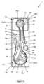
先ず、図1aおよび図1bを参照すると、ポンプ装置1は、第1の蠕動ポンプ12、第2の蠕動ポンプ14、およびポンプハウジング16を含んでいる。 1a and 1b, the
第一の蠕動ポンプ12は、一般に、成形された実質的に硬質のプラスチック材料で形成された第一のロータ18と、内部に第一のロータ18が回転可能に取り付けられた円筒状の第一のステータ19とを備えている。第一のロータ18は、複数の押圧部材20としての丸い突出部22を備えており、丸い突出部22は、第一のスピンドル24と一体的に形成され、第一のスピンドル24から半径方向外側に突出し、第一のスピンドル24の周上で等間隔に配置されている。本実施形態では、第一のロータ18は、3つの丸い突出部22を備えているが、第一のロータ18は、任意の適切な数の丸い突出部22を備え得ることが理解されるであろう。また、他のタイプの押圧部材20、例えばローラが使用され得ることも理解されるであろう。第一のスピンドル24は、電気モータの駆動シャフトなどの第一の外部回転駆動部28a(図10および図11)によって係合可能な中央駆動開口部26を備えている。 The first
第一の蠕動ポンプ12は、ポリ塩化ビニルなどの任意の適切な弾力性のあるプラスチック材料で形成され得る第一の可撓性チューブ30を備えている。第一の可撓性チューブ30は、粘性を有する液体などの流動性製品が第一の蠕動ポンプ12に送達される入口側32と、流動性製品が第一の蠕動ポンプ12から送達される出口側34とを有する。入口側32および出口側34は、第一のロータ18の回転の順方向(図1aでは時計回り)に対して指定されている。入口側32は、出口多岐管38の第一の出口ポート38aに連結され、出口側34は、第一の製品出口コネクタ40に連結されている。第一の可撓性チューブ30は、内壁19aに接触して円筒状の第一のステータ19の周囲を周方向に延びており、入口側32および出口側34は、円筒状の第一のステータ19から実質的に半径方向に離隔して外側に延びている。The first
第二の蠕動ポンプ14は、一般に、成形された実質的に硬質のプラスチック材料で形成された第二のロータ42と、内部に第二のロータ42が回転可能に取り付けられた円筒状の第二のステータ44とを備えている。第二のロータ42は、複数の押圧部材46としての丸い突出部48を備えており、丸い突出部48は、第二のスピンドル50と一体的に形成され、第二のスピンドル50から半径方向外側に突出し、第二のスピンドル50の周上で等間隔に配置されている。本実施形態では、第二のロータ42は、3つの丸い突出部48を備えているが、第二のロータ42は、任意の適切な数の丸い突出部48を備え得ることが理解されるであろう。また、他のタイプの押圧部材46、例えばローラが使用され得ることも理解されるであろう。第二のスピンドル50は、電気モータの駆動シャフトなどの第二の外部回転駆動部28b(図10および図11)によって係合可能な中央駆動開口部52を備えている。 The second
第二の蠕動ポンプ14は、ポリ塩化ビニルなどの任意の適切な弾力性のあるプラスチック材料で形成され得る第二の可撓性チューブ54を備えている。第二の可撓性チューブ54は、粘性を有する液体などの流動性製品が第二の蠕動ポンプ14に送達される入口側56と、流動性製品が第二の蠕動ポンプ14から送達される出口側58とを有する。入口側56および出口側58は、第二のロータ42の回転の順方向(図1aでは時計回り)に対して指定されている。入口側56は、出口多岐管38の第二の出口ポート38bに連結され、出口側58は、第二の製品出口コネクタ60に連結されている。第二の可撓性チューブ54は、内壁44aに接触して円筒状の第二のステータ44の周囲を周方向に延びており、入口側56および出口側58は、円筒状の第二のステータ44から実質的に半径方向に離隔して外側に延びている。 The second
円筒状の第一のステータ19は第一の半径r1を有し、円筒状の第二のステータ44は第二の半径r2を有する。第一の半径r1は、第二の半径r2よりも大きく、一般的には少なくとも20%大きい。さらに、本実施形態では、第一の可撓性チューブ30は、第二の可撓性チューブ54の直径、特に内径よりも大きい直径、特に内径を有する。本明細書で先に説明したように、第一および第二のステータ19,44、およびそれらに関連付けられた第一および第二のロータ18,42の直径が異なること、ならびに、必要に応じて第一および第二の蠕動ポンプ12,14の第一および第二の可撓性チューブ30,54の直径が異なることにより、各蠕動ポンプ12,14が異なる送液特性を有することになる。特に、より大径の第一の可撓性チューブ30を備えた、より大きな第一の蠕動ポンプ12は、比較的短時間で大量の液体または他の流動性製品を送達することが可能であるのに対し、より小径の第二の可撓性チューブ54を備えた、より小さな第二の蠕動ポンプ14は、液体または他の流動性製品を、より少量ではあるが、より高精度に送達することが可能である。 The cylindrical
第一および第二の蠕動ポンプ12,14は同一平面上にあり、特に第一および第二のロータ18,42が同一平面上にある。第一および第二のステータ19,44も同様に同一平面上にある。第一および第二のロータ18,42は、互いに実質的に平行であり、かつ互いに離間している回転軸を有している。 The first and second
ポンプハウジング16は、一般に、成形された実質的に硬質のプラスチック材料で形成されている。図1aおよび図1bに示された実施形態では、第一のステータ19、特に第一の内壁19aは、ポンプハウジング16内に円形の凹部62aとしてポンプハウジング16によって形成されている。第二のステータ44は、ポンプハウジング16における相補的な形状の凹部66a内に取り付けられたステータブロック64aを含んでいる。ステータブロック64aの寸法は、凹部66aの寸法よりも僅かに小さくされており、それによりステータブロック64aが凹部66a内で、ひいてはポンプハウジング16内で横方向に移動可能とされている。この横方向の移動により、図2(a)~図2(d)に図示されているように、第二のステータ44およびそれに関連付けられた第二のロータ42が、第一のステータ19およびそれに関連付けられた第一のロータ18に対して、同一平面内で相対的に移動することが可能になる。ポンプ装置1は、第一のステータ19に対する上述の横方向の相対移動を許容する一方で、ステータブロック64aをポンプハウジング16の凹部66a内に保持するための保持手段(図示せず)を備えている。
第一および第二の製品出口コネクタ40,60は、それぞれ、第一および第二のロータ18,42の回転軸と実質的に平行な出口軸を有する。これにより、ポンプ装置1、特に第一および第二のロータ18,42を、第一および第二の外部回転駆動部28a,28bと容易に係合および係合解除させることができる。また、これにより、ポンプ装置1、特に第一および第二の製品出口コネクタ40、60を、外部に取り付けられた第一および第二の製品入口コネクタ72a、72b(図10および図11)に係合させることができる。第一および第二の製品出口コネクタ40,60と外部に取り付けられた第一および第二の製品入口コネクタ72a,72bとの位置合わせを容易にするために、第一および第二の製品出口コネクタ40,60は、ポンプハウジング16の凹部74a,74bに取り付けられている。凹部74a,74bは、それぞれ対応するコネクタ40,60の外径よりも大きい直径を有している。それゆえ、横方向に移動可能な第二のステータ44およびそれに関連付けられた横方向に移動可能な第二のロータ42と同じ平面内で、コネクタ40,60が、ポンプハウジング16の凹部74a,74b内で横方向に移動することができる。The first and second
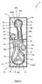
次に、図3には、第二の実施形態として、ポンプ装置2が示されている。ポンプ装置2は、図1a~図2を参照して上述したポンプ装置1と類似しており、対応する部材は同一の符号が付されている。 Next, FIG. 3 shows a
ポンプ装置2では、第二のステータ44、特に第二の内壁44aは、ポンプハウジング16内に円形の凹部62bとしてポンプハウジング16によって形成されている。第一のステータ19は、ポンプハウジング16における相補的な形状の凹部66b内に取り付けられたステータブロック64bを含んでいる。ステータブロック64bの寸法は、凹部66bの寸法よりも僅かに小さくされており、それによりステータブロック64bがポンプハウジング16の凹部66b内で横方向に移動可能とされている。この横方向の移動により、第一のステータ19およびそれに関連付けられた第一のロータ18が、第二のステータ44およびそれに関連付けられた第二のロータ42に対して、同一平面内で相対的に移動することが可能になる。ポンプ装置2は、第二のステータ44に対する上述の横方向の相対移動を許容する一方で、ステータブロック64bをポンプハウジング16の凹部66b内に保持するための保持手段(図示せず)を備えている。 In the
次に、図4には、第三の実施形態として、ポンプ装置3が示されている。ポンプ装置3は、図1a~図3を参照して上述したポンプ装置1,2と類似しており、対応する部材は同一の符号が付されている。 Next, FIG. 4 shows a pump device 3 as a third embodiment. The pumping device 3 is similar to the
ポンプ装置3では、第一のステータ19は、ポンプハウジング16における相補的な形状の凹部66b内に取り付けられたステータブロック64bを含んでいる。ステータブロック64bの寸法は、上述したように、凹部66bの寸法よりも僅かに小さくされており、それによりステータブロック64bがポンプハウジング16の凹部66b内で横方向に移動可能とされている。第二のステータ44もまた、ポンプハウジング16における相補的な形状の凹部66a内に取り付けられたステータブロック64aを含んでいる。ステータブロック64aの寸法は、上述したように、凹部66aの寸法よりも僅かに小さくされており、それによりステータブロック64aがポンプハウジング16の凹部66a内で横方向に移動可能とされている。本実施形態では、ステータブロック64a,64bの両方がそれぞれ対応する凹部66a,66b内で横方向に移動することにより、第一および第二のステータ19,44、ならびにそれらに関連付けられた第一および第二のロータ18,42が同一平面内で互いに対して相対的に移動可能とされていることが理解されるであろう。 In the pump device 3 , the
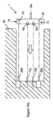
次に、図5には、第四の実施形態として、ポンプ装置4が示されている。ポンプ装置4は、図1a~図2を参照して上述したポンプ装置1と類似しており、対応する部材は同一の符号が付されている。 Next, FIG. 5 shows a pump device 4 as a fourth embodiment. The pumping device 4 is similar to the
ポンプ装置4では、第一のステータ19、特に第一の内壁19aは、ポンプハウジング16内に円形の凹部62aとしてポンプハウジング16によって形成されている。第二のステータ44は、ステータブロック64cを含んでおり、ステータブロック64cは、図5の矢印で図示されるように、ポンプハウジング16に対して相対的に横方向に移動するように、ポンプハウジング16の湾曲した端部に取り付けられている。前述のように、この横方向の移動によって、第二のステータ44およびそれに関連付けられた第二のロータ42が、第一のステータ19およびそれに関連付けられた第一のロータ18に対して、同一平面内で相対的に移動することが可能になる。ポンプ装置4は、ポンプハウジング16および第一のステータ19に対する上述の横方向の移動を許容する一方で、ステータブロック64cをポンプハウジング16の端部上の所定位置に保持するための保持手段(図示せず)を備えている。 In the pump device 4 the
次に、図6には、第五の実施形態として、ポンプ装置5が示されている。ポンプ装置5は、上述したポンプ装置と類似しており、対応する部材は同一の符号が付されている。 Next, FIG. 6 shows a pump device 5 as a fifth embodiment. The pumping device 5 is similar to the pumping device described above and corresponding parts are numbered the same.
ポンプ装置5では、ポンプハウジング16は、第一、第二および第三のハウジング部品16a~16cを含んでいる。第一および第二のステータ19,44、特にそれぞれの第一および第二の内壁19a,44aは、第一および第二のハウジング部品16a,16b内に円形の凹部62a,62bとして第一および第二のハウジング部品16a,16bによって形成されている。第一および第二のハウジング部品16a,16bは、第三のハウジング部品16cに移動可能に取り付けられており、図6の矢印で図示されるように、同一平面内で互いに相対的に移動可能である。より具体的には、第一および第二のハウジング部品16a,16bは共に、可撓性マウント70a,70bによって、第三のハウジング部品16cの互いに反対側の端部に取り付けられている。可撓性マウント70a,70bは、一般にゴムなどの弾力性のある材料を含んでいる。第一および第二の製品出口コネクタ40,60は、第三のハウジング部品16cに取り付けられている。 In pump device 5, pump
次に、図7には、第六の実施形態として、ポンプ装置6が示されている。ポンプ装置6は、図6を参照して上述したポンプ装置5と類似しており、対応する部材は同一の符号が付されている。 Next, FIG. 7 shows a pump device 6 as a sixth embodiment. The pumping device 6 is similar to the pumping device 5 described above with reference to FIG. 6 and corresponding parts are numbered the same.
ポンプ装置6では、ポンプハウジング16は、第一、第二および第三のハウジング部品16a~16cを含んでいる。第一および第二のステータ19,44、特にそれぞれの第一および第二の内壁19a,44aは、第一および第二のハウジング部品16a,16b内に円形の凹部62a,62bとして第一および第二のハウジング部品16a,16bによって形成されている。第一の製品出口コネクタ40は第二のハウジング部品16bに取り付けられ、第二の製品出口コネクタ60は第一のハウジング部品16aに取り付けられている。 In pump device 6, pump
第一、第二および第三のハウジング部品16a~16cは、シャーシまたは弾力性マウント90内において、同一平面内で互いに相対移動するように取り付けられている。シャーシまたは弾力性マウント90は、一般にゴムなどの弾力性のある材料を含んでいる。 The first, second and
次に、図8には、第七の実施形態として、ポンプ装置7が示されている。ポンプ装置7は、図7を参照して上述したポンプ装置6と類似しており、対応する部材は同一の符号が付されている。 Next, FIG. 8 shows a pump device 7 as a seventh embodiment. The pumping device 7 is similar to the pumping device 6 described above with reference to FIG. 7 and corresponding parts are numbered the same.
ポンプ装置7では、ポンプハウジング16は、第一~第五のハウジング部品16a~16eを含んでいる。第一および第二のステータ19,44、特にそれぞれの第一および第二の内壁19a,44aは、第一および第二のハウジング部品16a,16b内に円形の凹部62a,62bとして第一および第二のハウジング部品16a,16bによって形成されている。第一の製品出口コネクタ40は第三のハウジング部品16cに取り付けられ、第二の製品出口コネクタ60は第四のハウジング部品16dに取り付けられている。 In the pump device 7, the
ハウジング部品16a~16eは、シャーシまたは弾力性マウント90内において、同一平面内で互いに相対移動するように取り付けられている。シャーシまたは弾力性マウント90は、一般にゴムなどの弾力性のある材料を含んでいる。 The
次に、図9には、第八の実施形態として、ポンプ装置8が示されている。ポンプ装置8は、上述したポンプ装置と類似しており、対応する部材は同一の符号が付されている。 Next, FIG. 9 shows a
ポンプ装置8では、ポンプハウジング16は、第一および第二のハウジング部品16a,16bを含んでいる。第一および第二のステータ19,44、特にそれぞれの第一および第二の内壁19a,44aは、第一および第二のハウジング部品16a,16b内に円形の凹部62a,62bとして第一および第二のハウジング部品16a,16bによって形成されている。第一および第二のハウジング部品16a,16bは、シャーシまたは弾力性マウント90内において、同一平面内で互いに相対移動するように取り付けられている。シャーシまたは弾力性マウント90は、一般にゴムなどの弾力性のある材料を含んでいる。 In
第一および第二の製品出口コネクタ40,60もまた、シャーシまたは弾力性マウント90内において、互いに対して相対的に、かつ第一および第二のステータ19,44に対して相対的に移動するように独立して取り付けられている。 The first and second
次に図10aおよび図10bを参照すると、第一の実施例では、ポンプ装置1は、流動性製品を収容する、気密性のある可撓性パウチ80に着脱可能に連結可能とされている。可撓性パウチ80から流動性製品を送達するために、ポンプ装置1は、先ず、図10aに概略的に示されているように、分注装置82上に位置決めされ得る。位置決めの間、第一および第二のロータ18,42の第一および第二のスピンドル24,50における中央駆動開口部26,52は、第一および第二の外部回転駆動部28a,28bとそれぞれ係合する。第二のステータ44、ひいては第二のロータ42が、第一のステータ19、ひいては第一のロータ18に対して横方向に相対的に移動可能であることから、第一および第二の外部回転駆動部28a,28bと中央駆動開口部26,52とが正確に係合されることが保証される。 Referring now to Figures 10a and 10b, in a first embodiment the
また、第一および第二の製品出口コネクタ40,60は、ポンプ装置1の分注装置82上での位置決めの間、外部に取り付けられた第一および第二の製品入口コネクタ72a,72bとそれぞれ係合する。上述したように、第一および第二の製品出口コネクタ40,60が、ポンプハウジング16の標準より大きな凹部74a,74b内で横方向に移動可能であることから、第一および第二の製品出口コネクタ40,60と第一および第二の製品入口コネクタ72a,72bとが正確に位置合わせおよび係合されることが保証される。 The first and second
図10bに示すように、ポンプ装置1が分注装置82上に位置決めされると、可撓性パウチ80をポンプ装置1に連結することができ、特に可撓性パウチ80の出口84を出口多岐管38の入口ポート38cに連結することができる。出口多岐管38により、第一の可撓性チューブ30の入口側32と第二の可撓性チューブ54の入口側56の両方が、可撓性パウチ80内の流動性製品と同時に連通することが確実になる。可撓性パウチ80は、例えば段ボールで形成された硬質容器86内に取り付けることができるが、これは厳密には必要ではないことが理解されるであろう。 As shown in Figure 10b, when the
次に図11を参照すると、第二の実施例では、図10aおよび図10bを参照して上述した方法で、ポンプ装置1が流動性製品を含む気密性を有する可撓性パウチ80に連結されている。この第二の実施例では、ポンプ装置1および連結された可撓性パウチ80の両方が硬質容器86内に配設されている。硬質容器86は、同様に、段ボール素材で形成されていてもよい。 Referring now to Figure 11, in a second embodiment, the
可撓性パウチ80から流動性製品を送達するために、図11に概略的に示されているように、硬質容器86は、分注装置82上に位置決めされる。位置決めの間、第一および第二のロータ18,42の第一および第二のスピンドル24,50における中央駆動開口部26,52は、第一および第二の外部回転駆動部28a,28bとそれぞれ係合する。第二のステータ44、ひいては第二のロータ42が、第一のステータ19、ひいては第一のロータ18に対して横方向に相対的に移動可能であることから、第一および第二の外部回転駆動部28a,28bと中央駆動開口部26,52とが正確に係合されることが保証される。 To deliver the fluent product from
また、第一および第二の製品出口コネクタ40,60は、硬質容器86の分注装置82上での位置決めの間、外部に取り付けられた第一および第二の製品入口コネクタ72a,72bとそれぞれ係合する。上述したように、第一および第二の製品出口コネクタ40,60が、ポンプハウジング16の標準より大きな凹部74a,74b内で横方向に移動可能であることから、第一および第二の製品出口コネクタ40,60と第一および第二の製品入口コネクタ72a,72bとが正確に位置合わせおよび係合されることが保証される。 The first and second
次に、図12には、第九の実施形態として、ポンプ装置9が示されている。ポンプ装置9は、図1a~図2を参照して上述したポンプ装置1と類似しており、対応する部材は同一の符号が付されている。 Next, FIG. 12 shows a
ポンプ装置9では、第一および第二の可撓性チューブ30,54は、それぞれ、その出口側34,58において、第一および第二の製品出口100,102としての第一および第二の分注針104,106を備えている。第一および第二の分注針104,106は、取付部材110によって支持体(図示せず)に取り付け可能な分注ユニット108を形成する。これにより、第一および第二の分注針104,106は、共通の容器に直接、流動性製品を分注することができる。 In the
第一の分注針104は、第二の分注針106の直径、特に内径よりも大きな直径、特に内径を有する。より大径の第一の分注針104は、より大径の第一の可撓性チューブ30を備えた、より大きな第一の蠕動ポンプ12の動作中に、比較的短時間で大量の液体または他の流動性製品を分注するのに適しているのに対し、より小径の第二の分注針106は、より小径の第二の可撓性チューブ54を備えた、より小さな第二の蠕動ポンプ14の動作中に、液体または他の流動性製品を、より少量ではあるが、より高精度に分注するのに適していることが理解されるであろう。 The
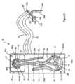
次に図13を参照すると、ポンプ装置9は、図11を参照して上述したのと同様に、流動性製品を収容する気密性を有する可撓性パウチ80に連結されている。 Referring now to FIG. 13, the
可撓性パウチ80から流動性製品を送達するために、図13に概略的に示されているように、硬質容器86は、分注装置82上に位置決めされる。位置決めの間、第一および第二のロータ18,42の第一および第二のスピンドル24,50における中央駆動開口部26,52は、第一および第二の外部回転駆動部28a,28bとそれぞれ係合する。上述したように、第二のステータ44、ひいては第二のロータ42が、第一のステータ19、ひいては第一のロータ18に対して横方向に相対的に移動可能であることから、第一および第二の外部回転駆動部28a,28bと中央駆動開口部26,52とが正確に係合されることが保証される。 To deliver the fluent product from
第一および第二の可撓性チューブ30,54は、第一および第二の蠕動ポンプ12,14から硬質容器86を通って、可撓性パウチ80に沿って巧く離れて延びており、第一および第二の外部回転駆動部28a,28bと中央駆動開口部26,52との係合を妨げないようになっている。上述したように、第一および第二の分注針104,106を含んでいる分注ユニット108は、支持体(図示せず)に取付部材110を係合させることにより、支持体に取り付けることができる。 the first and second
代表的な実施形態を前の段落で説明してきたが、添付の特許請求の範囲から逸脱することなく、これらの実施形態に対して様々な修正を加えることができることを理解されたい。したがって、特許請求の範囲の広さおよび範囲は、上述の代表的な実施形態に限定されるべきではない。 While representative embodiments have been described in the preceding paragraphs, it should be appreciated that various modifications can be made to these embodiments without departing from the scope of the appended claims. Therefore, the breadth and scope of the claims should not be limited to the exemplary embodiments described above.
上記特徴の全ての考え得る変形における任意の組み合わせは、特に断りのない限り、または文脈によって明らかに矛盾しない限り、本発明に含まれる。 Any combination of the above-described features in all possible variations thereof is encompassed by the invention unless otherwise indicated herein or otherwise clearly contradicted by context.
文脈から明らかにそうでないことを要求していない限り、明細書および特許請求の範囲全体を通して、「備えるまたは含む」,「備えているまたは含んでいる」などの語は、排他的または網羅的な意味とは対照的に包括的に解釈されるべきである。すなわち、「含むが、これに限定されない」という意味である。 Throughout the specification and claims, unless the context clearly requires otherwise, the words "comprising or including," "comprising or including," etc. are not intended to be exclusive or exhaustive. should be interpreted inclusively as opposed to meaning. That is, in the sense of "including, but not limited to."
Claims (32)
Translated fromJapanese内部で前記第一のロータが回転可能な円筒状の第一のステータであって、第一の半径を有する円周状の第一の内壁を備えた第一のステータと、
入口側と出口側を有し、前記第一の内壁に接触して前記第一のステータの周囲を周方向に延びている第一の可撓性チューブと、
を含む第一の蠕動ポンプと、
少なくとも1つの押圧部材を有する駆動可能な第二のロータと、
内部で前記第二のロータが回転可能な円筒状の第二のステータであって、第二の半径を有する円周状の第二の内壁を備えた第二のステータと、
入口側と出口側を有し、前記第二の内壁に接触して前記第二のステータの周囲を周方向に延びている第二の可撓性チューブと、
を含む第二の蠕動ポンプと、を含んでおり、
前記第一の半径が前記第二の半径よりも大きくされていると共に、前記第一のステータおよび前記第二のステータの少なくとも一方が該第一のステータおよび該第二のステータの他方に対して相対的に移動可能である
ことを特徴とする流動性製品を分注するためのポンプ装置。a drivable first rotor having at least one pressing member;
a cylindrical first stator within which the first rotor is rotatable, the first stator having a circumferential first inner wall having a first radius;
a first flexible tube having an inlet side and an outlet side and extending circumferentially around the first stator in contact with the first inner wall;
a first peristaltic pump comprising
a second drivable rotor having at least one pressing member;
a cylindrical second stator within which the second rotor is rotatable, the second stator having a circumferential second inner wall having a second radius;
a second flexible tube having an inlet side and an outlet side and extending circumferentially around the second stator in contact with the second inner wall;
a second peristaltic pump comprising
The first radius is larger than the second radius, and at least one of the first stator and the second stator is positioned relative to the other of the first stator and the second stator. A pump device for dispensing flowable products, characterized in that it is relatively movable.
前記第一の可撓性チューブの前記入口側が前記第一の流動性製品源と連通していると共に、
前記第二の可撓性チューブの前記入口側が前記第二の流動性製品源と連通している
請求項1~24のいずれか一項に記載の流動性製品を分注するためのポンプ装置。further comprising a first source of fluent product and a second source of fluent product not in communication with the first source of fluent product;
said inlet side of said first flexible tube is in communication with said first source of fluent product;
A pumping device for dispensing a fluent product according to any one of the preceding claims, wherein said inlet side of said second flexible tube communicates with said second source of fluent product.
Applications Claiming Priority (3)
| Application Number | Priority Date | Filing Date | Title |
|---|---|---|---|
| GB1805144.1AGB2572402B (en) | 2018-03-29 | 2018-03-29 | A pumping apparatus with first and second peristaltic pumps |
| GB1805144.1 | 2018-03-29 | ||
| PCT/GB2019/050898WO2019186176A1 (en) | 2018-03-29 | 2019-03-28 | A pumping apparatus for dispensing a flowable product |
Publications (2)
| Publication Number | Publication Date |
|---|---|
| JP2021519879A JP2021519879A (en) | 2021-08-12 |
| JP7324766B2true JP7324766B2 (en) | 2023-08-10 |
Family
ID=62142247
Family Applications (1)
| Application Number | Title | Priority Date | Filing Date |
|---|---|---|---|
| JP2020552243AActiveJP7324766B2 (en) | 2018-03-29 | 2019-03-28 | Pump device for dosing flowable products |
Country Status (11)
| Country | Link |
|---|---|
| US (1) | US11913443B2 (en) |
| EP (1) | EP3775554B1 (en) |
| JP (1) | JP7324766B2 (en) |
| AU (1) | AU2019244412B2 (en) |
| BR (1) | BR112020019617A2 (en) |
| CA (1) | CA3095237A1 (en) |
| DK (1) | DK3775554T3 (en) |
| ES (1) | ES2922178T3 (en) |
| GB (1) | GB2572402B (en) |
| MX (1) | MX2020010224A (en) |
| WO (1) | WO2019186176A1 (en) |
Citations (3)
| Publication number | Priority date | Publication date | Assignee | Title |
|---|---|---|---|---|
| JP2004239224A (en) | 2003-02-07 | 2004-08-26 | Ckd Corp | Tube pump |
| JP2014005780A (en) | 2012-06-25 | 2014-01-16 | Osaka Univ | Tube pump |
| JP2017538069A (en) | 2014-12-10 | 2017-12-21 | ホッジズ アンド ドレイク デザイン リミテッドHodges & Drake Design Limited | Peristaltic pump |
Family Cites Families (20)
| Publication number | Priority date | Publication date | Assignee | Title |
|---|---|---|---|---|
| US3489525A (en)* | 1967-08-25 | 1970-01-13 | Scientific Industries | System of automatic analysis |
| US4519754A (en)* | 1981-09-29 | 1985-05-28 | Minick Dale E | Peristaltic pump having variable occlusion rates |
| JPS61171886U (en)* | 1985-04-15 | 1986-10-25 | ||
| US4856972A (en)* | 1988-06-09 | 1989-08-15 | Fisher Scientific Co. | Dual roller peristaltic pump |
| FR2714080B1 (en)* | 1993-12-16 | 1996-03-01 | Dalic | Device for the electrochemical, in particular localized, treatment of a conductive substrate. |
| GB2285837B (en)* | 1994-01-24 | 1998-05-13 | Varian Australia | Peristaltic pump |
| RU2086111C1 (en) | 1995-05-16 | 1997-08-10 | Саутиев Николай Данилович | Hose-type pump |
| JP2000185092A (en)* | 1998-12-24 | 2000-07-04 | Nidek Co Ltd | Perfusion suction device |
| DE10043490C2 (en) | 2000-09-01 | 2003-05-22 | Heraeus Kulzer Gmbh & Co Kg | Device for mixing two flowable reaction components |
| EP1533597A1 (en)* | 2003-11-20 | 2005-05-25 | Millipore Corporation | Fluid dispensing device |
| US20050159696A1 (en)* | 2004-01-21 | 2005-07-21 | Steven Bernard | Tapered tubing for use in extracorporeal circuit for peripheral vein fluid removal |
| US7591639B2 (en)* | 2004-04-27 | 2009-09-22 | Hewlett-Packard Development Company, L.P. | Peristaltic pump |
| US20090092507A1 (en)* | 2005-08-05 | 2009-04-09 | Ramirez Jr Emilio A | Fluid pump systems |
| US20070059184A1 (en)* | 2005-09-15 | 2007-03-15 | Bach David T | Flow optical analysis for peristaltic and other rotary pumps |
| US7997448B1 (en)* | 2007-02-01 | 2011-08-16 | Robert Leyva | Universal beverage dispenser |
| US9518576B1 (en)* | 2010-07-15 | 2016-12-13 | Elemental Scientific, Inc. | Peristaltic pump |
| WO2012048261A2 (en)* | 2010-10-07 | 2012-04-12 | Vanderbilt University | Peristaltic micropump and related systems and methods |
| DE102013210548A1 (en)* | 2013-06-06 | 2014-12-11 | Bausch + Ströbel Maschinenfabrik Ilshofen GmbH + Co. KG | Peristaltic pump with reduced pulsation and use of peristaltic pump |
| JP6884137B2 (en)* | 2015-08-25 | 2021-06-09 | グローバル・ライフ・サイエンシズ・ソリューションズ・ユーエスエー・エルエルシー | Improvements in and related to biomanufacturing equipment |
| US11104587B2 (en)* | 2016-04-14 | 2021-08-31 | Nch Corporation | System and method for automated control, feed, delivery verification, and inventory management of corrosion and scale treatment products for water systems |
- 2018
- 2018-03-29GBGB1805144.1Apatent/GB2572402B/ennot_activeExpired - Fee Related
- 2019
- 2019-03-28BRBR112020019617-7Apatent/BR112020019617A2/enactiveSearch and Examination
- 2019-03-28EPEP19721337.4Apatent/EP3775554B1/enactiveActive
- 2019-03-28WOPCT/GB2019/050898patent/WO2019186176A1/ennot_activeCeased
- 2019-03-28MXMX2020010224Apatent/MX2020010224A/enunknown
- 2019-03-28CACA3095237Apatent/CA3095237A1/enactivePending
- 2019-03-28DKDK19721337.4Tpatent/DK3775554T3/enactive
- 2019-03-28JPJP2020552243Apatent/JP7324766B2/enactiveActive
- 2019-03-28ESES19721337Tpatent/ES2922178T3/enactiveActive
- 2019-03-28USUS17/042,666patent/US11913443B2/enactiveActive
- 2019-03-28AUAU2019244412Apatent/AU2019244412B2/ennot_activeCeased
Patent Citations (3)
| Publication number | Priority date | Publication date | Assignee | Title |
|---|---|---|---|---|
| JP2004239224A (en) | 2003-02-07 | 2004-08-26 | Ckd Corp | Tube pump |
| JP2014005780A (en) | 2012-06-25 | 2014-01-16 | Osaka Univ | Tube pump |
| JP2017538069A (en) | 2014-12-10 | 2017-12-21 | ホッジズ アンド ドレイク デザイン リミテッドHodges & Drake Design Limited | Peristaltic pump |
Also Published As
| Publication number | Publication date |
|---|---|
| AU2019244412A1 (en) | 2020-10-15 |
| ES2922178T3 (en) | 2022-09-09 |
| US20210140421A1 (en) | 2021-05-13 |
| DK3775554T3 (en) | 2022-07-11 |
| US11913443B2 (en) | 2024-02-27 |
| JP2021519879A (en) | 2021-08-12 |
| EP3775554A1 (en) | 2021-02-17 |
| GB2572402A (en) | 2019-10-02 |
| CA3095237A1 (en) | 2019-10-03 |
| MX2020010224A (en) | 2021-01-15 |
| WO2019186176A1 (en) | 2019-10-03 |
| AU2019244412B2 (en) | 2024-05-02 |
| EP3775554B1 (en) | 2022-04-13 |
| RU2020135325A (en) | 2022-04-29 |
| BR112020019617A2 (en) | 2021-01-05 |
| GB2572402B (en) | 2020-06-17 |
| GB201805144D0 (en) | 2018-05-16 |
Similar Documents
| Publication | Publication Date | Title |
|---|---|---|
| EP2753833B1 (en) | Linear peristaltic pump | |
| CN102711870B (en) | Cylinder pump | |
| TW201313171A (en) | Foam pump | |
| AU2016201186A1 (en) | Beverage cartridge | |
| CN108496005A (en) | Micro- dosage peristaltic pump of fluid for micro- dosage | |
| AU2012320537A1 (en) | Pump fittings and methods for their manufacture | |
| JP2020534469A (en) | Rotary pump driven drug delivery device | |
| JP7324766B2 (en) | Pump device for dosing flowable products | |
| US5140747A (en) | Method for assembling a peristaltic pump | |
| RU2788661C2 (en) | Pump unit for dosing fluid product | |
| JP5693566B2 (en) | Dose injection device | |
| TW202227191A (en) | Discharge device and discharge system capable of sufficiently discharging air in a fluid storage section where a fluid flows in and out inside a housing | |
| CN102422133B (en) | Dosing unit for cip/sip | |
| KR101615745B1 (en) | Drug infusion pump including stackable curved syringe | |
| WO2022118003A1 (en) | Pump |
Legal Events
| Date | Code | Title | Description |
|---|---|---|---|
| A521 | Request for written amendment filed | Free format text:JAPANESE INTERMEDIATE CODE: A523 Effective date:20201204 | |
| A621 | Written request for application examination | Free format text:JAPANESE INTERMEDIATE CODE: A621 Effective date:20220310 | |
| A131 | Notification of reasons for refusal | Free format text:JAPANESE INTERMEDIATE CODE: A131 Effective date:20230330 | |
| A521 | Request for written amendment filed | Free format text:JAPANESE INTERMEDIATE CODE: A523 Effective date:20230620 | |
| TRDD | Decision of grant or rejection written | ||
| A01 | Written decision to grant a patent or to grant a registration (utility model) | Free format text:JAPANESE INTERMEDIATE CODE: A01 Effective date:20230704 | |
| A61 | First payment of annual fees (during grant procedure) | Free format text:JAPANESE INTERMEDIATE CODE: A61 Effective date:20230731 | |
| R150 | Certificate of patent or registration of utility model | Ref document number:7324766 Country of ref document:JP Free format text:JAPANESE INTERMEDIATE CODE: R150 |