JP7323352B2 - Biological information measuring device - Google Patents
Biological information measuring deviceDownload PDFInfo
- Publication number
- JP7323352B2 JP7323352B2JP2019119151AJP2019119151AJP7323352B2JP 7323352 B2JP7323352 B2JP 7323352B2JP 2019119151 AJP2019119151 AJP 2019119151AJP 2019119151 AJP2019119151 AJP 2019119151AJP 7323352 B2JP7323352 B2JP 7323352B2
- Authority
- JP
- Japan
- Prior art keywords
- unit
- measurement
- biological information
- opening
- closing
- Prior art date
- Legal status (The legal status is an assumption and is not a legal conclusion. Google has not performed a legal analysis and makes no representation as to the accuracy of the status listed.)
- Active
Links
- 238000005259measurementMethods0.000claimsdescription132
- 230000001133accelerationEffects0.000claimsdescription49
- 239000000523sampleSubstances0.000claimsdescription24
- 238000001514detection methodMethods0.000claimsdescription22
- 229910052760oxygenInorganic materials0.000description90
- 239000001301oxygenSubstances0.000description90
- QVGXLLKOCUKJST-UHFFFAOYSA-Natomic oxygenChemical compound[O]QVGXLLKOCUKJST-UHFFFAOYSA-N0.000description89
- 239000008280bloodSubstances0.000description49
- 210000004369bloodAnatomy0.000description49
- 230000006870functionEffects0.000description14
- 238000000034methodMethods0.000description9
- 238000003780insertionMethods0.000description8
- 230000037431insertionEffects0.000description8
- 230000008569processEffects0.000description8
- 230000008859changeEffects0.000description7
- 238000004891communicationMethods0.000description7
- 238000013500data storageMethods0.000description6
- 230000000694effectsEffects0.000description6
- 238000006243chemical reactionMethods0.000description5
- 238000012545processingMethods0.000description4
- 102000001554HemoglobinsHuman genes0.000description3
- 108010054147HemoglobinsProteins0.000description3
- 238000010586diagramMethods0.000description3
- 238000002640oxygen therapyMethods0.000description3
- 238000000926separation methodMethods0.000description3
- 238000002835absorbanceMethods0.000description2
- 238000006073displacement reactionMethods0.000description2
- 210000000624ear auricleAnatomy0.000description2
- 210000003414extremityAnatomy0.000description2
- 238000012986modificationMethods0.000description2
- 230000004048modificationEffects0.000description2
- 230000000284resting effectEffects0.000description2
- 210000003371toeAnatomy0.000description2
- 238000007792additionMethods0.000description1
- 230000003321amplificationEffects0.000description1
- 230000005540biological transmissionEffects0.000description1
- 238000004364calculation methodMethods0.000description1
- 238000012790confirmationMethods0.000description1
- 210000003811fingerAnatomy0.000description1
- 230000004907fluxEffects0.000description1
- 238000009532heart rate measurementMethods0.000description1
- 238000007726management methodMethods0.000description1
- 239000000463materialSubstances0.000description1
- 238000003199nucleic acid amplification methodMethods0.000description1
- 230000000474nursing effectEffects0.000description1
- 150000002926oxygenChemical class0.000description1
- 230000010412perfusionEffects0.000description1
- 230000037081physical activityEffects0.000description1
- 238000012805post-processingMethods0.000description1
- 238000004393prognosisMethods0.000description1
- 208000023504respiratory system diseaseDiseases0.000description1
- 230000004044responseEffects0.000description1
- 230000001360synchronised effectEffects0.000description1
- 230000001960triggered effectEffects0.000description1
Images


Classifications
- Y—GENERAL TAGGING OF NEW TECHNOLOGICAL DEVELOPMENTS; GENERAL TAGGING OF CROSS-SECTIONAL TECHNOLOGIES SPANNING OVER SEVERAL SECTIONS OF THE IPC; TECHNICAL SUBJECTS COVERED BY FORMER USPC CROSS-REFERENCE ART COLLECTIONS [XRACs] AND DIGESTS
- Y02—TECHNOLOGIES OR APPLICATIONS FOR MITIGATION OR ADAPTATION AGAINST CLIMATE CHANGE
- Y02D—CLIMATE CHANGE MITIGATION TECHNOLOGIES IN INFORMATION AND COMMUNICATION TECHNOLOGIES [ICT], I.E. INFORMATION AND COMMUNICATION TECHNOLOGIES AIMING AT THE REDUCTION OF THEIR OWN ENERGY USE
- Y02D30/00—Reducing energy consumption in communication networks
- Y02D30/70—Reducing energy consumption in communication networks in wireless communication networks
Landscapes
- Measuring Pulse, Heart Rate, Blood Pressure Or Blood Flow (AREA)
- Measurement Of The Respiration, Hearing Ability, Form, And Blood Characteristics Of Living Organisms (AREA)
Description
Translated fromJapanese本発明は、生体情報として例えば経皮的動脈血酸素飽和度(SpO2)等の生体パラメータを測定する生体情報測定装置に関する。The present invention relates to a biological information measuring apparatus for measuring biological parameters such as percutaneous arterial oxygen saturation (SpO2 ) as biological information.
生体パラメータを測定する生体情報測定装置として、経皮的動脈血酸素飽和度(SpO2)を測定するパルスオキシメータが知られている。パルスオキシメータは、光によって非観血的に動脈血酸素飽和度(SpO2)を計測するための医療機器であり、その計測のために通常はプローブが指、足趾又は耳朶等の部位に装着されるよう構成されている。A pulse oximeter that measures percutaneous arterial blood oxygen saturation (SpO2 ) is known as a biological information measuring device that measures biological parameters. A pulse oximeter is a medical device for noninvasively measuring arterial blood oxygen saturation (SpO2 ) with light, and for that measurement, a probe is usually attached to a site such as a finger, toe, or earlobe. configured to be
一般的な、パルスオキシメータでは、装着された部位に向けて例えば赤色光及び赤外光を発光する発光素子が設けられ、下側のハウジングに、装着部位を透過した光を検出する受光素子が設けられている。血液中のヘモグロビンは酸素との結合の有無により赤色光と赤外光の吸光度が異なることから、発光素子が発光する光が指先等を透過したもの又は反射したものを受光素子で測定して分析することにより、経皮的動脈血酸素飽和度を測定することができる。 In a general pulse oximeter, a light-emitting element that emits, for example, red light and infrared light is provided toward the site where it is worn, and a light-receiving element that detects light transmitted through the site where it is worn is provided in the lower housing. is provided. Since the absorbance of red light and infrared light differs depending on whether or not hemoglobin in blood is bound to oxygen, the light emitted by the light-emitting element is measured and analyzed by a light-receiving element that is transmitted through or reflected from a fingertip, etc. By doing so, percutaneous arterial oxygen saturation can be measured.
近年、電子部品の小型化に伴い、パルスオキシメータも、小型軽量化が実現され、手術室以外での用途として、例えば、在宅での患者自身による呼吸器疾患の検査や訪問看護での使用も可能となっている。小型化されたパルスオキシメータとしては、手に持てる大きさのハンドヘルド型、片手で保持できるワンハンドグリップ型、腕時計型、指先に取り付ける発光素子及び受光素子に表示部も一体化された一体型の指用のパルスオキシメータ等のさまざまな形態のものが知られている。 In recent years, along with the miniaturization of electronic components, the size and weight of pulse oximeters have also been reduced. As applications other than the operating room, for example, patients themselves can examine respiratory diseases at home and use them in home nursing. It is possible. Miniaturized pulse oximeters include a handheld type that can be held in the hand, a one-hand grip type that can be held with one hand, a wristwatch type, and an integrated finger type that integrates a light-emitting element and a light-receiving element attached to the fingertip. Various forms are known, such as pulse oximeters for human use.
例えば、特許文献1に示すパルスオキシメータは、指先に装着して使用可能な小型軽量のクリップ型のパルスオキシメータである。このパルスオキシメータは、発光素子及び受光素子を用いて経皮的動脈血酸素飽和度(血中酸素飽和度)を取得するプローブ部と、取得された生体信号を測定分析処理して経皮的動脈血酸素飽和度の測定および記録を行う本体部とを一体化して構成されている。 For example, the pulse oximeter disclosed in
引用文献1に示すような一体型のパルスオキシメータにおいて、経皮的動脈血酸素飽和度(SpO2)を計測する際、ハウジングの計測可能な位置への患者の指の挿入タイミングは患者の任意である。これにより、操作スイッチ等の操作により電源を入れて、常に計測部の発光素子を発光させることより、指が計測位置に挿入されるまで待機させている。
このため従来のパルスオキシメータでは、経皮的動脈血酸素飽和度を測定していないときも発光素子を発光させており、電源オンの後、直ぐに測定しない場合も多い。このような非測定状態時であっても常に発光素子は点灯しているため、消費電流が大きくなり、特に電池式の場合、電池を無駄に消費してしまうという問題がある。
また、特許文献1に示すパルスオキシメータのように、測定開始を操作する操作ボタンを備える構造では、筐体に孔部が形成され、この孔部に操作ボタンを押下自在に設けている。このため、筐体自体の防水機能は低下することになる。
特に、在宅で用いられるパルスオキシメータとしては、経皮的動脈血酸素飽和度を測定する場面を選ばないように高い防水性を有することが望まれている。When measuring percutaneous arterial blood oxygen saturation (SpO2) with an integrated pulse oximeter as shown in
For this reason, in the conventional pulse oximeter, the light emitting element emits light even when the percutaneous arterial blood oxygen saturation is not being measured, and in many cases the measurement is not performed immediately after the power is turned on. Since the light-emitting element is always lit even in such a non-measurement state, current consumption increases, and especially in the case of a battery type, there is a problem that the battery is wasted.
Further, in a structure including an operation button for operating the start of measurement, such as the pulse oximeter disclosed in
In particular, pulse oximeters used at home are desired to have high waterproofness so that percutaneous arterial blood oxygen saturation can be measured in any situation.
本発明はかかる点に鑑みてなされたものであり、防水性を確保して消費電力の低減化を図り、経皮的動脈血酸素飽和度計測を効率よく好適に実行することができる生体情報測定装置を提供することを目的とする。 The present invention has been made in view of the above points, and is a biological information measuring apparatus that ensures waterproofness, reduces power consumption, and is capable of efficiently and suitably performing percutaneous arterial blood oxygen saturation measurement. intended to provide
本発明の生体情報測定装置は、
使用者が携帯して使用可能な生体情報測定装置であって、
開閉自在な開閉部位を有する筐体を有し、前記開閉部位により使用者の測定部位を挟み前記測定部位において、前記使用者の生体情報を計測するクリップ式のプローブ部を有する生体情報計測部と、
前記生体情報計測部に電源を供給して計測を可能にする駆動源と、
前記プローブ部の開閉を検出する開閉検知部と、
を有し、
前記駆動源は、前記開閉検知部により前記プローブ部の開状態が検知されるとき、前記生体情報計測部に電源の供給を開始して、前記生体情報計測部による生体情報の計測を可能にし、
加速度センサを有し、前記加速度センサの出力に基づいて前記使用者の歩数を計測する歩数計測部を更に備え、
前記生体情報計測部は、前記開閉部位における前記測定部位の挟持状態と前記開閉部位からの前記測定部位の離脱状態とを検知可能であり、
前記駆動源は、前記生体情報計測部の計測中においては前記歩数計測部に電源を供給せず、前記生体情報計測部により前記測定部位の離脱状態が検知されたとき、前記歩数計測部への電源の供給を開始して、前記歩数計測部による歩数の計測を可能にし、前記測定部位の離脱状態が所定時間の継続した場合、前記生体情報計測部への電源供給を停止する構成を採る。
また、本発明の生体情報測定装置は、
使用者が携帯して使用可能な生体情報測定装置であって、
開閉自在な開閉部位を有する筐体を有し、前記開閉部位により使用者の測定部位を挟み前記測定部位における前記使用者の生体情報を計測するクリップ式のプローブ部を有する生体情報計測部と、
前記生体情報計測部に電源を供給して計測を可能にする駆動源と、
前記プローブ部の開閉を検出する開閉検知部と、
加速度センサと、
前記加速度センサの出力に基づいて前記使用者の歩数を計測する歩数計測部と、
を有し、
前記生体情報計測部は、前記開閉部位における前記測定部位の状態を検知可能であり、
前記駆動源は、
前記開閉検知部により前記プローブ部の開状態が検知されるとき、前記生体情報計測部に電源の供給を開始して前記生体情報の計測を可能にし、前記生体情報計測部の計測中においては前記歩数計測部に電源を供給せず、前記測定部位の状態に基づいて、前記歩数計測部への電源の供給を開始して、前記歩数計測部による歩数の計測を可能にする構成を採る。The biological information measuring device of the present invention is
A biological information measuring device that can be carried and used by a user,
a biological information measurement unit having a housing having an opening/closing part that can be opened and closed, and having a clip-type probe part that sandwiches a measurement part of the user between the opening/closing parts and measures the biological information of the user at the measurement part; ,
a driving source that supplies power to the biological information measuring unit to enable measurement;
an opening/closing detection unit that detects opening/closing of the probe unit;
has
The driving source starts supplying power to the biological information measuring unit when the open/close detecting unit detects the open state of the probe unit,thereby enabling the biological information measuring unit to measure biological information.,
further comprising a step counting unit that has an acceleration sensor and measures the number of steps of the user based on the output of the acceleration sensor;
The biological information measuring unit is capable of detecting a sandwiching state of the measurement site at the opening and closing site and a detachment state of the measurement site from the opening and closing site,
The drive source does not supply power to the step count measurement unit during measurement by the biological information measurement unit, and when the biological information measurement unit detects that the measurement site is detached, the drive source supplies power to the step count measurement unit. A power supply is started to allow the number of steps to be measured by the number-of-steps measuring unit, and power supply to the biological information measuring unit is stopped when the state of separation of the measurement site continues for a predetermined period of time.
Further, the biological information measuring device of the present invention is
A biological information measuring device that can be carried and used bya user ,
a biological information measurement unit having a housing having an opening/closing part that can be opened and closed, and having a clip-type probe part that sandwiches a measurement part of a user between the opening/closing parts and measures the biological information of the user at the measurement part;
a driving source that supplies power to the biological information measuring unit to enable measurement;
an opening/closing detection unit that detects opening/closing of the probe unit;
an acceleration sensor;
a step counting unit that measures the number of steps of the user based on the output of the acceleration sensor;
has
The biological information measuring unit is capable of detectingthe state of the measurement site at the opening and closing site,
The driving source is
When the open/close detection unit detects the open state of the probe unit, power supply to the biological information measurement unit is started to enable measurement of the biological information, and during measurement by the biological information measurement unit, theA configuration in which power is not supplied to the pedometer, and power is supplied to the pedometerbased onthe state of the measurement site, so that the pedometercan measure the number of steps.take.
本発明によれば、防水性を確保して消費電力の低減化を図り、経皮的動脈血酸素飽和度や脈波等の生体情報の計測を効率よく好適に実行することができる生体情報測定装置を実現する。 INDUSTRIAL APPLICABILITY According to the present invention, a biological information measuring apparatus is capable of securing waterproofness, reducing power consumption, and efficiently and suitably measuring biological information such as percutaneous arterial blood oxygen saturation and pulse wave. Realize
以下、本発明の実施の形態について、図面を用いて詳細に説明する。 BEST MODE FOR CARRYING OUT THE INVENTION Hereinafter, embodiments of the present invention will be described in detail with reference to the drawings.
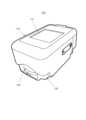
図1は、本発明の一実施の形態に係る生体情報測定装置の一例であるパルスオキシメータの外観の一例を示す図である。パルスオキシメータ100は、プローブ部と本体部が、上部筐体及び下部筐体として一体化され、電源部を収容した、指先に装着するタイプのパルスオキシメータである。本実施の形態のパルスオキシメータ100は、例えば、酸素濃縮器を用いた在宅酸素療法の経過観察において用いられる。この場合に用いられるパルスオキシメータ100は、使用者としての患者の在宅酸素療法の経過の確認(予後の確認)のための判断材料としての、身体活動性の指標となる活動量の一例としての歩数を計測する歩数計測機能を有する。なお、本実施の形態では、生体情報測定装置としてパルスオキシメータを一例として説明するが、これに限らず、クリップ状のプローブ部により生体パラメータを測定する生体情報測定装置であれば、どのような装置であってもよい。 FIG. 1 is a diagram showing an example of the appearance of a pulse oximeter, which is an example of a biological information measuring device according to an embodiment of the present invention. The
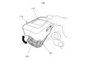
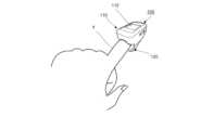
図1~図3に示すパルスオキシメータ100は、クリップ状のプローブ部を有し、プローブ部は、ヒンジ部130により開閉可能に接続された上部筐体(開閉部位)110及び下部筐体(開閉部位)120により構成されている。ヒンジ部130は、上部筐体110と下部筐体120とを閉じる方向に回転力を発生するよう設けられている。これにより、パルスオキシメータ100は、上部筐体110と下部筐体120との間の指挿入口140に矢印の方向で挿入された患者の指Yを、適度な力で挟み込む(図5及び図6参照)ことができる。すなわち、上部筐体110、下部筐体120、およびヒンジ部130は、全体として、患者の指Yに取り外し可能に装着される。 The
また、パルスオキシメータ100は、上部筐体110の上面に、表示部であるディスプレイ112を有する。なお、パルスオキシメータ100は、図示しないが、上部筐体110の後面には、主駆動電源としての電池(第1電源部に相当)を収容する電池収容部が開口して設けられ、この開口は電池蓋により水密的に開閉自在に閉塞されている。この電池蓋で閉塞される部位には、例えば、電池収容部近傍にミニUSBコネクタ等の外部接続可能なコネクタ(図示せず)が設けられている。外部接続可能なコネクタは、アダプタ(図示せず)を介して、外部装置との間のデータの送受信を可能とする。
ディスプレイ112は、時刻、測定値、および動作状況等を表示する。ディスプレイ112は、制御部180の制御を受けて測定値として経皮的動脈血酸素飽和度(SpO2:以下、「動脈血酸素飽和度」ともいう)、脈波、脈拍数、歩数等を表示する。ディスプレイ112は、例えば、歩数計測モード、動脈血酸素飽和度計測モード等の複数のモードのそれそれで測定値を表示してもよい。Further, the
A
また、ディスプレイ112は、モードに応じて電池残量を表示可能である。具体的な表示形態としては、ディスプレイ112は、電池残量表示として、パルスオキシメータ100に収容された第1電源部162のメイン電池の残量の目安を、容易に視認できるように模式的に表示する。
ディスプレイ112は、動脈血酸素飽和度計測時では、動脈血酸素飽和度計測モードの表示画面として、測定された経皮的動脈血酸素飽和度を、「%SpO2」の単位で表示する。また、これに加えて、ディスプレイ112は、電池残量、バーグラフで表示した脈波、「数字+PR bpm」で測定した脈拍数を表示する。なお、バーグラフのバーの長さは、検出された脈波の検出強度に対応する。また、経皮的動脈血酸素飽和度とともに測定された灌流指数(PI)が十分なものでないとき、例えば、経皮的動脈血酸素飽和度の数字を点滅させる。
また、歩数計測モード時では、歩数計測モード表示画面としてディスプレイに歩数を表示してもよく、表示しなくてもよい。Also, the
During arterial oxygen saturation measurement, the
Further, in the step counting mode, the number of steps may or may not be displayed on the display as the step counting mode display screen.
経皮的動脈血酸素飽和度計測中では、患者は、経皮的動脈血酸素飽和度の計測値その他の情報を、ディスプレイ112により確認することができる。また、計測された計測値は、データ記憶部125(図4参照)に記録される。 During the percutaneous arterial oxygen saturation measurement, the patient can view the percutaneous arterial oxygen saturation measurement and other information via the
なお、患者には、経皮的動脈血酸素飽和度の測定が行われ、記録されたときに、その旨を記録通知により知るようにしてもよい。更に、連続装着時間が長すぎるときには、その旨を警告通知により知るようにしてもよい。 When the percutaneous arterial blood oxygen saturation is measured and recorded, the patient may be informed of the fact by a record notification. Furthermore, when the continuous wearing time is too long, it may be notified by a warning notification to that effect.
図4は、パルスオキシメータ100の構成の一例を示すブロック図である。 FIG. 4 is a block diagram showing an example of the configuration of the
図4のパルスオキシメータ100は、経皮的動脈血酸素飽和度計測部(以下、「酸素飽和度計測部」という)150、第1電源部(駆動源)162、第2電源部(駆動源)164、時計・カレンダ機能部165、歩数計測部166、開閉検知部168、制御部180、ディスプレイ(表示部)112、データ通信部124、データ記憶部125を有する。 The
酸素飽和度計測部150は、発光素子152、受光素子154を有し、発光素子152、受光素子154は、所謂、生体情報として、経皮的動脈血酸素飽和度を計測するプローブ部として機能する。この酸素飽和度計測部150は、経皮的動脈血酸素飽和度とともに脈拍数(つまり脈波測定値)を計測する。
発光素子152により、赤色光や赤外光を発光して患者の特定部位(例えば、指先、つま先等)に透過させ、その透過光を受光素子154により検出することにより、検出信号を得る。酸素飽和度計測部150は、検出信号を制御部180の酸素飽和度計測回路(図示せず)に出力し、酸素飽和度計測回路において、検出信号に基づいて酸素飽和度及び脈拍数が測定される。The oxygen
The light-emitting
発光素子152及び受光素子154は、本実施の形態では、指挿入口140を構成する上部筐体110及び下部筐体120に配置される。発光素子152は、例えば、発光ダイオードであり、受光素子154は、例えば、フォトダイオードである。発光ダイオードは、制御部180(具体的には制御部180の図示しない発光駆動回路)の駆動制御を受けて、異なる所定の波長の光を発光する。フォトダイオードは、2つの所定の波長の光を受光したときに、その受光量に応じた電流信号を、制御部180(具体的には制御部180の電流電圧変換回路)へ出力する。プローブ部を構成する発光素子152が発光および受光する光は、例えば、赤外光と赤色光である。発光素子152及び受光素子154は、第1電源部162からの電力供給により駆動する。 Light-emitting
第1電源部162は、パルスオキシメータ100の主駆動電源であり、パルスオキシメータ100の各部、例えば、制御部180、開閉検知部168、酸素飽和度計測部150の発光素子152及び受光素子154等に電力を供給して、それぞれを駆動する。 The first
本実施の形態では、第1電源部162は、乾電池であり、電池蓋により閉塞される電池収容部に交換可能に収容される。 In this embodiment, the first
第2電源部164は、第1電源部162よりも電源容量が小さく、消費電力も小さい。第2電源部164は、ボタン電池等が用いられる、所謂、内部電池であり、時計やパルスオキシメータ100におけるBIOS等のバックアップメモリのデータ保存等に使用される。本実施の形態では、第2電源部164は、時計・カレンダ機能部165に電力供給するとともに、第1電源部162から各部へ電力供給されていない状態、つまりパルスオキシメータ100の電源がオフの状態において、加速度センサ170に電力を供給する。 The second power supply section 164 has a smaller power supply capacity than the first
時計・カレンダ機能部165は、時間・カレンダを計測し、表示する。例えば、パルスオキシメータ100では、酸素飽和度計測部150が酸素飽和度と脈拍との測定を行った時点において時計・カレンダ機能部165が示していた日時として測定日時が記憶される。時計・カレンダ機能部165は、第2電源部164からの電源供給により駆動する。 The clock/
歩数計測部166は、患者の歩数を計測する。本実施の形態では、歩数計測部166は、加速度センサ170と、制御部180の歩数計数回路(図示せず)とを有し、加速度センサ170によりパルスオキシメータ100の加速度を測定する。 A
加速度センサ170は、パルスオキシメータ100の加速度(傾き、動きによる変位に基づく)を検知して、制御部180に出力する。制御部180では、加速度センサ170の出力に基づいて、患者の歩数を測定する。つまり、制御部180は、加速度センサ170とともに、患者が歩いた歩数を測定する歩数計測部として機能する。加速度センサ170は、パルスオキシメータ100の静止状態、移動状態を検出する。 The
加速度センサ170は、検知した測定結果を制御部180に送信し、制御部180の歩数計測回路(図示せず)により歩数計測が行われる。加速度センサ170における歩数計測は、加速度センサ170に、例えば、3軸加速度センサを適用し、3軸方向の加速度の合計値を用いる等して患者の歩数を測定する。なお、この歩数の測定により患者の歩行も判定できる。 The
加速度センサ170は、パルスオキシメータ100の使用開始時から、つまり、パルスオキシメータに初めて第1電源部162及び第2電源部164を装着したときから第1電源部162及び第2電源部164の少なくとも一方から電源が供給されている。本実施の形態では、加速度センサ170は、パルスオキシメータ100の使用開始時から第2電源部164からの電力供給により駆動する。 The
開閉検知部168は、上部筐体110及び下部筐体120の開閉状態を検知し、制御部180に出力する。すなわち、開閉検知部168は、パルスオキシメータ100において経皮的動脈血酸素飽和度を計測する前に、制御部180及び酸素飽和度計測部150を駆動して酸素飽和度を計測可能な状態にする。開閉検知部168は、例えば、ホール素子等の磁気センサ172と磁石174を有する。磁気センサ172によって、上部筐体110及び下部筐体120の距離による磁束の変化に基づいて、酸素飽和度測定のために、開閉部位(上部筐体110及び下部筐体120)の開状態或いは閉状態を検出できる。なお、磁気センサ172と磁石174の位置は、上部筐体110及び下部筐体120の開閉状態を検知すれば、どのように設けられてもよく、図3に示すパルスオキシメータ100では、磁気センサ172と磁石174とを逆の位置にそれぞれ設けてもよい。 The open/
制御部180は、CPU、RAM、ROMを備える。制御部180では、ROM等の記憶媒体に格納された制御プログラムの実行により、モード設定、測定値の算出、およびパルスオキシメータ100の各部の制御を行う。
制御部180は、酸素飽和度及び脈拍数(つまり脈波測定値)を計測する酸素飽和度計測回路(図示せず)を有する。制御部180は、酸素飽和度計測回路(図示せず)により、開閉検知部168の検知結果(ここでは加速度センサ170の検出結果)をトリガーに駆動して、動脈血の総ヘモグロビンに対する酸化ヘモグロビンの割合を求め、動脈血の脈拍に同期する吸光度の変化を検出する。この検出結果をディジタルデータに変換することにより、制御部180は、酸素飽和度測定値及び脈拍測定値を取得する。酸素飽和度計測回路は、例えば、電流電圧変換回路、復調回路、信号処理回路及び発光駆動回路等を有する。電流電圧変換回路は、酸素飽和度計測部150から入力される電流信号を電圧信号に変換し、電圧信号を復調回路へ出力する。復調回路は、発光駆動回路から入力される信号を受けて、電流電圧変換回路から入力される電圧信号を、上述の波長に対応する成分毎に分離して2つの観測信号を復調する。そして、復調回路は、復調した観測信号を、信号処理回路へ出力する。信号処理回路は、復調回路から入力される2つの観測信号に対して所定の信号処理(例えば、増幅およびA/D変換など)を行い、処理後の観測信号を算出する。発光駆動回路は、CPU制御を受けて、発光素子152である2つの発光ダイオードを発光させる。The control unit 180 includes a CPU, RAM, and ROM. The control unit 180 executes a control program stored in a storage medium such as a ROM to perform mode setting, measurement value calculation, and control of each unit of the
The control unit 180 has an oxygen saturation measurement circuit (not shown) that measures oxygen saturation and pulse rate (that is, pulse wave measurement value). The control unit 180 is driven by an oxygen saturation measurement circuit (not shown) triggered by the detection result of the opening/closing detection unit 168 (here, the detection result of the acceleration sensor 170), and measures the ratio of oxygenated hemoglobin to total hemoglobin in arterial blood. is obtained, and the change in absorbance synchronized with the arterial blood pulse is detected. By converting this detection result into digital data, the control unit 180 acquires the oxygen saturation measurement value and the pulse measurement value. The oxygen saturation measurement circuit has, for example, a current-voltage conversion circuit, a demodulation circuit, a signal processing circuit, a light emission drive circuit, and the like. The current-voltage conversion circuit converts the current signal input from the oxygen
制御部180は、加速度センサ170とともに歩数計測部166として機能し、加速度センサ170からのデータに基づいて歩数を計測する。制御部180は、計測した歩数をディスプレイ112に表示したり、データ記憶部125に記録したりする。 Control unit 180 functions as
制御部180は、各部の入力される信号に基づいて、経皮的動脈血酸素飽和度計測モード、歩数計測モードとしてディスプレイ112に表示する。制御部180は、磁気センサ172からの信号により、発光素子152を発光させて受光素子154で受光する等、酸素飽和度計測部150を駆動して、酸素飽和度の計測を開始可能な状態にする。パルスオキシメータ100が停止状態において、加速度センサ170から、パルスオキシメータ100の移動を示す信号が入力されると、第1電源部162から制御部180を介して歩数計測部166を可能にする各部への電源供給を行う。
また、制御部180は、経皮的動脈血酸素飽和度を計測しているときには、歩数計測を停止する。また、歩数計測時において経皮的動脈血酸素飽和度の計測を始めた際には、歩数計測を停止する。The control unit 180 displays the percutaneous arterial blood oxygen saturation measurement mode and the number of steps measurement mode on the
Further, the control unit 180 stops the step count measurement while measuring the percutaneous arterial blood oxygen saturation. Further, when the measurement of the percutaneous arterial blood oxygen saturation is started during the step count measurement, the step count measurement is stopped.
データ通信部124は、パルスオキシメータ100と、例えば、酸素濃縮器或いは外部機器とを通信可能に接続するためのインターフェースである。パルスオキシメータ100と、酸素濃縮器との間の接続、及び、パルスオキシメータ100と在宅酸素療法管理装置等の外部装置との間の接続は、Bluetooth(登録商標)等の近距離無線通信方式に基づく無線通信により行われる。パルスオキシメータ100と酸素濃縮器とは、常時通信可能な接続ではなく、互いに近距離にいて無線通信チャネルが確立されている間、通信が可能となる。 The
データ記憶部125は、フラッシュメモリなどの書き換え可能な不揮発性メモリ(図示せず)を含み、制御部180の制御を受けて、測定結果を記録できる。 The
本実施の形態の駆動動作について説明する。 The drive operation of this embodiment will be described.
図7は、パルスオキシメータ100の動作の一例を示すフローチャートである。 FIG. 7 is a flow chart showing an example of the operation of the
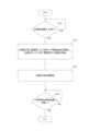
パルスオキシメータ100の動作は、上述の通り、制御部180によって制御される。また、制御部180は、経皮的動脈血酸素飽和度を測定するとともに、脈波および脈拍数等を測定して、これらの測定値記録および表示を行う。ここでは、シャットダウン状態、つまり、主電源が投入されていない状態のパルスオキシメータ100において自動的に主電源が投入されて歩行中の歩数を計測する歩数計の機能について説明する。 The operation of the
パルスオキシメータ100では、まず、パルスオキシメータ100が所定の場所に載置されている状態等の静止状態から姿勢が変化したか否かを判定する。すなわち、ステップS10において、加速度センサ170が、パルスオキシメータ100の加速度情報を検知したか否かを判定する。加速度センサ170は、パルスオキシメータ100がシャットダウン状態のとき、第2電源部164から常に省電力の電源供給を受けている。この状態において、加速度センサ170は、パルスオキシメータ100の静止状態からの姿勢の変化、つまり、パルスオキシメータ100の変位があるかを検出する。 The
ステップS10において、加速度情報を検知すれば、つまり、パルスオキシメータ100の変位を検知すれば、ステップS12に移行する。ステップS12では、パルスオキシメータ100の主電源オンとなり第1電源部162から各部への電源供給を開始し、且つ、加速度センサ170へ第1電源部162から電源を供給する。すなわち、歩数計測部166(加速度センサ170も含む)及び制御部180には、歩数の計測が可能になるように、第1電源部162から電力供給が開始される。具体的には、ステップS12では、加速度情報を検知した加速度センサ170は、第1電源部162に信号を出力し、信号を受けた第1電源部162は立ち上がり、制御部180及び各部に電源を供給する。これにより、ステップS14では、制御部180は、加速度センサ170とともに歩数計測部166として、歩数計測を開始する。また、第1電源部162が制御部180に電源を供給することにより、制御部180は、加速度センサ170の電源を第2電源部164から第1電源部162に切り換える。また、制御部180は、歩数計測モード表示制御を行い、ディスプレイ112に歩数の計測値を表示可能としてもよい。なお、本実施の形態では、制御部180に第1電源部162から電力供給されることにより、パルスオキシメータ100に電源が投入され、動脈血酸素飽和度計測部(具体的には、発光素子152)以外に電力が供給されて立ち上がる。 In step S10, if the acceleration information is detected, that is, if the displacement of the
パルスオキシメータ100は、患者に携帯され、その患者が歩行すると、自動的に電源が投入され、その歩数計測が可能な状態となる。なお、この状態では、発光素子152及び受光素子154へ電源が供給されておらず、経皮的動脈血酸素飽和度の計測モードにはなっていない。これにより、経皮的動脈血酸素飽和度を計測する際の電力を効率良く確保できる。 The
そして、ステップS16に示すように、一定期間経過しても加速度センサ170からの出力が無いかを判定し、一定期間、加速度センサ170からの加速度情報がない場合、パルスオキシメータ100による測定は停止したとみなし、処理を終了する。 Then, as shown in step S16, it is determined whether or not there is an output from the
また、本実施の形態に係るパルスオキシメータ100は、パルスオキシメータ100を持ち上げたり、パルスオキシメータ100を携帯して歩行中の歩数の計測をしようとされたりすることによって、パルスオキシメータ100の状態が変化すると、自動的に電源オフから電源オン状態となり歩数の計測を開始する。つまり、主電源である第1電源部162から制御部180を介してパルスオキシメータ100の主要部への電力供給がされていない状態であっても、加速度センサ170のパルスオキシメータ100の状態の変化の検知により、酸素飽和度計測部150を除く主要部に電源が投入される。特に、パルスオキシメータ100では、歩数計測部166として機能するための電源が投入される。例えば、加速度センサ170へは第2電源部から切り換えて第1電源部162から電力が供給され、また、歩数計測回路、ディスプレイ112の表示等が行われ、歩数計測部166は、歩数を計測する。
また、加速度センサ170の検知をトリガーにしてパルスオキシメータ100の磁気センサ172が駆動する(ステップS21)。In addition, the
Further, the detection of the
磁気センサ172は、ステップS22において、上部筐体110及び下部筐体120が開き、指挿入口140が開いた状態、つまり開状態であるかを判定する。指挿入口140が開いていれば、経皮的動脈血酸素飽和度を測定するものとみなし、ステップS23に移行する。 In step S22, the
ステップS23では、制御部180を介して酸素飽和度計測部150を駆動し、経皮的動脈血酸素飽和度の計測を開始する。具体的には、発光素子152及び受光素子154に電源を供給する。発光素子152は発光し、酸素飽和度測定可能状態で待機する。なお、制御部180の経皮的動脈血酸素飽和度を計測するための回路に電力が供給されるようにしてもよい。これにより計測可能な位置である計測位置に指Yの測定部位が挿入されると、ステップS24において、上部筐体110及び下部筐体120で挟持し、発光素子152及び受光素子154で検知し、経皮的動脈血酸素飽和度の計測を開始する。なお、経皮的動脈血酸素飽和度の計測に伴い脈波も計測している。 In step S23, the oxygen
次いで、ステップS25において、酸素飽和度計測部150(発光素子152及び受光素子154)により、開閉部位(上部筐体110及び下部筐体120)における計測位置から指の測定部位が抜けた状態(計測位置からの離脱状態)であるか否かを判定する。
ステップS25において、指の測定部位が計測位置から抜けていない場合、経皮的動脈血酸素飽和度の計測は継続され、指が抜けた状態、つまり測定部位が計測位置から抜けた状態と判定された場合、ステップS26に移行する。測定部位が計測位置から抜けた状態かどうかの判定には、例えば受光素子154で受光した光量の変化などを用いても良い。Next, in step S25, the oxygen saturation measurement unit 150 (the
In step S25, if the measurement site of the finger is not removed from the measurement position, the measurement of the percutaneous arterial blood oxygen saturation is continued, and it is determined that the finger is removed, that is, the measurement site is removed from the measurement position. If so, the process proceeds to step S26. A change in the amount of light received by the light-receiving
ステップS26では、制御部180は第1電源部162から、歩数計測部166への電源の供給を開始して、前記歩数計測部による歩数の計測を可能にする。
ステップS27では、酸素飽和度計測部150(発光素子152及び受光素子154)により、計測位置に指の測定部位が再挿入されている状態(測定部位を挟持した状態「挟持状態」)ともいう)であるか否かを判定する。ステップS27において、指の測定部位が計測位置にあれば、ステップS24に戻り、再び経皮的動脈血酸素飽和度の測定を開始し、再挿入無しの状態(測定部位の離脱状態)であれば、ステップS28に移行する。In step S26, the control unit 180 starts supplying power from the first
In step S27, the oxygen saturation measuring unit 150 (the
ステップS28では、開閉検知部168(磁気センサ172)の検知結果に基づいて、指挿入口140が閉じた状態であるか判定し、閉じた状態、つまり指挿入口140が閉状態であれば、ステップS29に移行する。 In step S28, based on the detection result of the open/close detector 168 (magnetic sensor 172), it is determined whether the
ステップS29において、制御部180は、指挿入口140が閉状態で一定時間(例えば30秒)経過しているか否かを判定する。ステップS29において、一定時間経過していると判定すれば、ステップS30に移行して、電源オフ、つまり第1電源部162から動脈血酸素飽和度計測部150への電源供給を停止し、経皮的動脈血酸素飽和度の計測を停止して終了する。
その後、歩数計測も一定期間、実行されなければ、パルスオキシメータ100はシャットダウン状態になる。つまり、一定期間(例えば数分)、歩行が行われなければ、パルスオキシメータ100では、第1電源部162から加速度センサ170以外に供給される電源はオフになり、加速度センサ170のみに電源が供給された省電力モードの待機状態に戻る。In step S29, the control unit 180 determines whether or not a certain period of time (for example, 30 seconds) has passed with the
After that, the
このように本実施の形態によれば、電源オンの状態や電源オンで歩数計測が実行されている状態でも常に発光素子152及び受光素子154に電源供給されている従来のパルスオキシメータと異なり、経皮的動脈血酸素飽和度測定時にのみ発光素子152及び受光素子154に電源供給を行うことができる。
これにより、酸素飽和度計測部150の発光素子152及び受光素子154を駆動させるためのボタンを別途設ける必要が無く、ボタンを筐体に設けるための孔部の必要も無く、筐体の防水性を高めることができる。よって、本実施の形態によれば、防水性を確保して消費電力の低減化を図り、経皮的動脈血酸素飽和度や脈波等の生体情報の計測を効率よく好適に実行することができる。As described above, according to the present embodiment, unlike the conventional pulse oximeter in which power is always supplied to the
As a result, there is no need to separately provide a button for driving the
また、発光素子152及び受光素子154を有する酸素飽和度計測部(生体情報計測部)150が脈血酸素飽和度を計測中であれば、歩数計測部166による歩数計測は行われない。しかし、経皮的動脈血酸素飽和度を計測しているときに、指の測定部位を挟持する計測位置から、測定部位が離脱した状態を検知すると、歩数計測を開始する。そして、所定時間内、例えば、10秒内で、再び指が計測位置に配置(測定部位が計測位置で挟持された状態)されると、第1電源部162或いは制御部180は、経皮的動脈血酸素飽和度計測及び歩数計測を所定時間(10秒間)行わせ、どちらの計測も選択して行わせるように制御する。これにより、通常、経皮的動脈血酸素飽和度等の生体情報の計測は、歩数等の活動量の計測よりも優先されるが、歩数などの活動量の計測を優先させることができる。
本実施の形態の場合、生体情報測定装置としてのパルスオキシメータのプローブ部により挟持される指を測定部位としたが、四肢(特に新生児の場合好適)、或いは耳朶を測定部位としてクリップ式のプローブ部で挟むようにし、経皮的動脈血酸素飽和度や脈波等の生体パラメータを計測してもよい。なお、クリップ式のプローブとは、開閉して使用者としての患者の測定部位を挟みように構成されていれば、回動したりスライドしたりどのように構成されてもよい。Further, if the oxygen saturation measuring unit (biological information measuring unit) 150 having the
In the case of the present embodiment, the finger sandwiched by the probe portion of the pulse oximeter as a biological information measuring device is used as the measurement site, but a clip-type probe can be used with the extremities (especially suitable for newborns) or the earlobe as the measurement site. It may be sandwiched between parts to percutaneously measure biological parameters such as arterial blood oxygen saturation and pulse wave. It should be noted that the clip-type probe may be configured in any manner, such as rotating or sliding, as long as it is configured to open and close and sandwich the measurement site of the patient as the user.
また、本実施の形態は、上述の例の他にも、種々変更して実施することができる。例えば、本実施の形態における上記の構成および動作は、使用者としての患者が携帯或いは装着して生体パラメータとしての経皮的動脈血酸素飽和度及び活動量としての歩数を計測しているが、非計測時では携帯或いは装着する必要がない他の各種生体情報測定装置においても実現可能である。例えば、本実施の形態の構成および動作は、経皮的動脈血酸素飽和度或いは脈波等の生体パラメータを計測する機能を有する全ての医療機器に適用可能である。 Further, the present embodiment can be implemented with various modifications other than the above-described example. For example, the above configuration and operation in the present embodiment are carried or worn by a patient as a user to measure the percutaneous arterial blood oxygen saturation as a biological parameter and the number of steps as an activity amount. It can also be realized in other various biological information measuring devices that do not need to be carried or worn during measurement. For example, the configuration and operation of this embodiment are applicable to all medical devices having a function of measuring biological parameters such as percutaneous arterial blood oxygen saturation or pulse wave.
また、本実施の形態では、生体情報測定装置としてパルスオキシメータを一例として説明したが、生体情報測定装置としては、心電計であっても良い。心電計は、患者の心電図を測定する際に患者の測定部位として四肢にクリップ状のプローブ部(電極)を用いる為、本実施の形態と同様に磁気センサ等で開状態を検知させることが出来る。この場合、計測位置からの測定部位の離脱は、測定部位が電極に離れる際の電極のインピーダンス変化により、検知することができる。これにより、開状態から、測定部位が電極から離れるまでの間のみ、心電図情報の取得が行われ、消費電力を削減することができる。 Further, in the present embodiment, the pulse oximeter has been described as an example of the biological information measuring device, but an electrocardiograph may be used as the biological information measuring device. Since the electrocardiograph uses clip-shaped probes (electrodes) on the extremities of the patient to measure the patient's electrocardiogram, the open state can be detected by a magnetic sensor or the like as in the present embodiment. I can. In this case, the separation of the measurement site from the measurement position can be detected by the impedance change of the electrode when the measurement site moves away from the electrode. As a result, electrocardiogram information is acquired only from the open state until the measurement site is separated from the electrodes, and power consumption can be reduced.
以上、本発明の実施の形態について説明した。なお、以上の説明は本発明の好適な実施の形態の例証であり、本発明の範囲はこれに限定されない。つまり、上記装置の構成や各部分の形状についての説明は一例であり、本発明の範囲においてこれらの例に対する様々な変更や追加が可能であることは明らかである。 The embodiments of the present invention have been described above. It should be noted that the above description is an illustration of preferred embodiments of the present invention, and the scope of the present invention is not limited thereto. In other words, the description of the configuration of the apparatus and the shape of each part is an example, and it is clear that various modifications and additions to these examples are possible within the scope of the present invention.
本発明に係る生体情報測定装置は、防水性を確保して消費電力の低減化を図り、経皮的経皮的動脈血酸素飽和度の計測や脈波等の生体情報の計測を効率よく好適に実行することができる効果を有し、一次或いは二次電池等により駆動する携帯型のパルスオキシメータとして有用である。 The biological information measuring device according to the present invention ensures waterproofness, reduces power consumption, and efficiently and suitably measures biological information such as percutaneous percutaneous arterial blood oxygen saturation measurement and pulse wave. It is useful as a portable pulse oximeter driven by a primary or secondary battery or the like, having the effect that it can be implemented.
100 パルスオキシメータ(生体情報測定装置)
110 上部筐体
112 ディスプレイ
120 下部筐体
124 データ通信部
125 データ記憶部
130 ヒンジ部
140 指挿入口
150 酸素飽和度計測部(生体情報計測部)
152 発光素子
154 受光素子
162 第1電源部
164 第2電源部
165 時計・カレンダ機能部
166 歩数計測部
168 開閉検知部
170 加速度センサ
172 磁気センサ
180 制御部100 pulse oximeter (biological information measuring device)
110
152 Light-emitting
Claims (3)
Translated fromJapanese開閉自在な開閉部位を有する筐体を有し、前記開閉部位により使用者の測定部位を挟み前記測定部位において、前記使用者の生体情報を計測するクリップ式のプローブ部を有する生体情報計測部と、
前記生体情報計測部に電源を供給して計測を可能にする駆動源と、
前記プローブ部の開閉を検出する開閉検知部と、
を有し、
前記駆動源は、前記開閉検知部により前記プローブ部の開状態が検知されるとき、前記生体情報計測部に電源の供給を開始して、前記生体情報計測部による生体情報の計測を可能にし、
加速度センサを有し、前記加速度センサの出力に基づいて前記使用者の歩数を計測する歩数計測部を更に備え、
前記生体情報計測部は、前記開閉部位における前記測定部位の挟持状態と前記開閉部位からの前記測定部位の離脱状態とを検知可能であり、
前記駆動源は、前記生体情報計測部の計測中においては前記歩数計測部に電源を供給せず、前記生体情報計測部により前記測定部位の離脱状態が検知されたとき、前記歩数計測部への電源の供給を開始して、前記歩数計測部による歩数の計測を可能にし、前記測定部位の離脱状態が所定時間の継続した場合、前記生体情報計測部への電源供給を停止する、
生体情報測定装置。A biological information measuring device that can be carried and used by a user,
a biological information measurement unit having a housing having an opening/closing part that can be opened and closed, and having a clip-type probe part that sandwiches a measurement part of the user between the opening/closing parts and measures the biological information of the user at the measurement part; ,
a driving source that supplies power to the biological information measuring unit to enable measurement;
an opening/closing detection unit that detects opening/closing of the probe unit;
has
The driving source starts supplying power to the biological information measuring unit when the open/close detecting unit detects the open state of the probe unit,thereby enabling the biological information measuring unit to measure biological information.,
further comprising a step counting unit that has an acceleration sensor and measures the number of steps of the user based on the output of the acceleration sensor;
The biological information measuring unit is capable of detecting a sandwiching state of the measurement site at the opening and closing site and a detachment state of the measurement site from the opening and closing site,
The drive source does not supply power to the step count measurement unit during measurement by the biological information measurement unit, and when the biological information measurement unit detects that the measurement site is detached, the drive source supplies power to the step count measurement unit. Power supply is started to allow the number of steps to be measured by the pedometer, and when the measurement site has been detached for a predetermined period of time, power supply to the biological information measurement unit is stopped.
Biological information measuring device.
開閉自在な開閉部位を有する筐体を有し、前記開閉部位により使用者の測定部位を挟み前記測定部位における前記使用者の生体情報を計測するクリップ式のプローブ部を有する生体情報計測部と、
前記生体情報計測部に電源を供給して計測を可能にする駆動源と、
前記プローブ部の開閉を検出する開閉検知部と、
加速度センサと、
前記加速度センサの出力に基づいて前記使用者の歩数を計測する歩数計測部と、
を有し、
前記生体情報計測部は、前記開閉部位における前記測定部位の状態を検知可能であり、
前記駆動源は、
前記開閉検知部により前記プローブ部の開状態が検知されるとき、前記生体情報計測部に電源の供給を開始して前記生体情報の計測を可能にし、前記生体情報計測部の計測中においては前記歩数計測部に電源を供給せず、前記測定部位の状態に基づいて、前記歩数計測部への電源の供給を開始して、前記歩数計測部による歩数の計測を可能にする、
生体情報測定装置。A biological information measuring device that can be carried and used bya user ,
a biological information measurement unit having a housing having an opening/closing part that can be opened and closed, and having a clip-type probe part that sandwiches a measurement part of a user between the opening/closing parts and measures the biological information of the user at the measurement part;
a driving source that supplies power to the biological information measuring unit to enable measurement;
an opening/closing detection unit that detects opening/closing of the probe unit;
an acceleration sensor;
a step counting unit that measures the number of steps of the user based on the output of the acceleration sensor;
has
The biological information measuring unit is capable of detectingthe state of the measurement site at the opening and closing site,
The driving source is
When the open/close detection unit detects the open state of the probe unit, power supply to the biological information measurement unit is started to enable measurement of the biological information, and during measurement by the biological information measurement unit, the Power is not supplied to the pedometer unit, and power supply to the pedometer unit is startedbased onthe state of the measurement siteto allow the pedometer unit to measure the number of steps.
Biological information measuring device.
請求項1または2に記載の生体情報測定装置。The drive source stops supplying power to the biological information measurement unit when the open/close detection unit detects the closed state of the probe unit.
The biological information measuring device according to claim 1 or 2.
Priority Applications (1)
| Application Number | Priority Date | Filing Date | Title |
|---|---|---|---|
| JP2019119151AJP7323352B2 (en) | 2019-06-26 | 2019-06-26 | Biological information measuring device |
Applications Claiming Priority (1)
| Application Number | Priority Date | Filing Date | Title |
|---|---|---|---|
| JP2019119151AJP7323352B2 (en) | 2019-06-26 | 2019-06-26 | Biological information measuring device |
Publications (2)
| Publication Number | Publication Date |
|---|---|
| JP2021003395A JP2021003395A (en) | 2021-01-14 |
| JP7323352B2true JP7323352B2 (en) | 2023-08-08 |
Family
ID=74096936
Family Applications (1)
| Application Number | Title | Priority Date | Filing Date |
|---|---|---|---|
| JP2019119151AActiveJP7323352B2 (en) | 2019-06-26 | 2019-06-26 | Biological information measuring device |
Country Status (1)
| Country | Link |
|---|---|
| JP (1) | JP7323352B2 (en) |
Citations (5)
| Publication number | Priority date | Publication date | Assignee | Title |
|---|---|---|---|---|
| JP2007144130A (en) | 2005-10-31 | 2007-06-14 | Konica Minolta Sensing Inc | Bio-information measuring device |
| JP2010264126A (en) | 2009-05-15 | 2010-11-25 | Konica Minolta Sensing Inc | Biological information measuring device |
| US20140194712A1 (en) | 2012-02-20 | 2014-07-10 | Contec Medical Systems Co., Ltd. | Digital portable pulse oximeter and battery-powered control method thereof |
| JP2017153581A (en) | 2016-02-29 | 2017-09-07 | フクダ電子株式会社 | Life activity display device, life activity display method, and walking test system |
| JP2017533737A (en) | 2014-09-22 | 2017-11-16 | クアルコム,インコーポレイテッド | Pulse oximeter with accelerometer |
- 2019
- 2019-06-26JPJP2019119151Apatent/JP7323352B2/enactiveActive
Patent Citations (5)
| Publication number | Priority date | Publication date | Assignee | Title |
|---|---|---|---|---|
| JP2007144130A (en) | 2005-10-31 | 2007-06-14 | Konica Minolta Sensing Inc | Bio-information measuring device |
| JP2010264126A (en) | 2009-05-15 | 2010-11-25 | Konica Minolta Sensing Inc | Biological information measuring device |
| US20140194712A1 (en) | 2012-02-20 | 2014-07-10 | Contec Medical Systems Co., Ltd. | Digital portable pulse oximeter and battery-powered control method thereof |
| JP2017533737A (en) | 2014-09-22 | 2017-11-16 | クアルコム,インコーポレイテッド | Pulse oximeter with accelerometer |
| JP2017153581A (en) | 2016-02-29 | 2017-09-07 | フクダ電子株式会社 | Life activity display device, life activity display method, and walking test system |
Also Published As
| Publication number | Publication date |
|---|---|
| JP2021003395A (en) | 2021-01-14 |
Similar Documents
| Publication | Publication Date | Title |
|---|---|---|
| US20210169345A1 (en) | Ring for optically measuring biometric data | |
| EP3197354B1 (en) | Medical device | |
| US8750954B2 (en) | Medical monitoring patch device and methods | |
| US6790178B1 (en) | Physiological monitor and associated computation, display and communication unit | |
| US20100240972A1 (en) | Slider Spot Check Pulse Oximeter | |
| US20200060555A1 (en) | Monitoring devices and methods | |
| EP2479575B1 (en) | Blood glucose meter | |
| TW201526868A (en) | Modular sensor platform | |
| EP2050391B1 (en) | Finger-clamp type oximeter with several display modes | |
| US20210145363A1 (en) | Measuring device | |
| WO2018152189A1 (en) | Photoplethysmographic wearable blood pressure monitoring system and methods | |
| KR20160105396A (en) | Battery charger related applications | |
| KR100877207B1 (en) | Non-invasive continuous blood pressure, arterial elasticity measuring device | |
| US11864923B2 (en) | Method for reducing melanin bias in pulse oximeters | |
| CN105796077A (en) | Detection glove | |
| JP5299079B2 (en) | Biological information measuring device | |
| US20140257060A1 (en) | Medical monitoring patch device and methods | |
| JP2007020836A (en) | Biomedical information measuring apparatus | |
| JP4534535B2 (en) | Biological evaluation apparatus and control method of biological evaluation apparatus | |
| JP7323352B2 (en) | Biological information measuring device | |
| CN202458381U (en) | Finger-clamping blood oxygen saturation measuring device having the capability of automatic power on/off and provided with pedometer | |
| JP2007044438A (en) | Electronic sphygmomanometer | |
| JP2006000481A (en) | Portable biological signal measuring device | |
| JP7343313B2 (en) | Biological information measuring device | |
| WO2025058913A1 (en) | Pulse oximeter |
Legal Events
| Date | Code | Title | Description |
|---|---|---|---|
| A621 | Written request for application examination | Free format text:JAPANESE INTERMEDIATE CODE: A621 Effective date:20220622 | |
| A977 | Report on retrieval | Free format text:JAPANESE INTERMEDIATE CODE: A971007 Effective date:20230228 | |
| A131 | Notification of reasons for refusal | Free format text:JAPANESE INTERMEDIATE CODE: A131 Effective date:20230307 | |
| A521 | Request for written amendment filed | Free format text:JAPANESE INTERMEDIATE CODE: A523 Effective date:20230502 | |
| TRDD | Decision of grant or rejection written | ||
| A01 | Written decision to grant a patent or to grant a registration (utility model) | Free format text:JAPANESE INTERMEDIATE CODE: A01 Effective date:20230711 | |
| A61 | First payment of annual fees (during grant procedure) | Free format text:JAPANESE INTERMEDIATE CODE: A61 Effective date:20230727 | |
| R150 | Certificate of patent or registration of utility model | Ref document number:7323352 Country of ref document:JP Free format text:JAPANESE INTERMEDIATE CODE: R150 |