JP7322638B2 - Printer and cassette for printing - Google Patents
Printer and cassette for printingDownload PDFInfo
- Publication number
- JP7322638B2 JP7322638B2JP2019178163AJP2019178163AJP7322638B2JP 7322638 B2JP7322638 B2JP 7322638B2JP 2019178163 AJP2019178163 AJP 2019178163AJP 2019178163 AJP2019178163 AJP 2019178163AJP 7322638 B2JP7322638 B2JP 7322638B2
- Authority
- JP
- Japan
- Prior art keywords
- printing
- cassette
- gear
- spool
- input
- Prior art date
- Legal status (The legal status is an assumption and is not a legal conclusion. Google has not performed a legal analysis and makes no representation as to the accuracy of the status listed.)
- Active
Links
- 230000005540biological transmissionEffects0.000claimsdescription10
- 238000004804windingMethods0.000claimsdescription10
- 238000011144upstream manufacturingMethods0.000claimsdescription5
- 230000002093peripheral effectEffects0.000description8
- 238000010586diagramMethods0.000description5
- 230000000694effectsEffects0.000description4
- 238000010438heat treatmentMethods0.000description2
- 230000037431insertionEffects0.000description2
- 238000003780insertionMethods0.000description2
- 238000010030laminatingMethods0.000description2
- 239000000463materialSubstances0.000description2
- 125000006850spacer groupChemical group0.000description2
- 101000856746Bos taurus Cytochrome c oxidase subunit 7A1, mitochondrialProteins0.000description1
- 239000000853adhesiveSubstances0.000description1
- 230000001070adhesive effectEffects0.000description1
- 230000007423decreaseEffects0.000description1
- 230000020169heat generationEffects0.000description1
Images


Classifications
- B—PERFORMING OPERATIONS; TRANSPORTING
- B41—PRINTING; LINING MACHINES; TYPEWRITERS; STAMPS
- B41J—TYPEWRITERS; SELECTIVE PRINTING MECHANISMS, i.e. MECHANISMS PRINTING OTHERWISE THAN FROM A FORME; CORRECTION OF TYPOGRAPHICAL ERRORS
- B41J15/00—Devices or arrangements of selective printing mechanisms, e.g. ink-jet printers or thermal printers, specially adapted for supporting or handling copy material in continuous form, e.g. webs
- B41J15/04—Supporting, feeding, or guiding devices; Mountings for web rolls or spindles
- B41J15/044—Cassettes or cartridges containing continuous copy material, tape, for setting into printing devices
- B—PERFORMING OPERATIONS; TRANSPORTING
- B41—PRINTING; LINING MACHINES; TYPEWRITERS; STAMPS
- B41J—TYPEWRITERS; SELECTIVE PRINTING MECHANISMS, i.e. MECHANISMS PRINTING OTHERWISE THAN FROM A FORME; CORRECTION OF TYPOGRAPHICAL ERRORS
- B41J15/00—Devices or arrangements of selective printing mechanisms, e.g. ink-jet printers or thermal printers, specially adapted for supporting or handling copy material in continuous form, e.g. webs
- B41J15/04—Supporting, feeding, or guiding devices; Mountings for web rolls or spindles
- B41J15/042—Supporting, feeding, or guiding devices; Mountings for web rolls or spindles for loading rolled-up continuous copy material into printers, e.g. for replacing a used-up paper roll; Point-of-sale printers with openable casings allowing access to the rolled-up continuous copy material
- B—PERFORMING OPERATIONS; TRANSPORTING
- B41—PRINTING; LINING MACHINES; TYPEWRITERS; STAMPS
- B41J—TYPEWRITERS; SELECTIVE PRINTING MECHANISMS, i.e. MECHANISMS PRINTING OTHERWISE THAN FROM A FORME; CORRECTION OF TYPOGRAPHICAL ERRORS
- B41J11/00—Devices or arrangements of selective printing mechanisms, e.g. ink-jet printers or thermal printers, for supporting or handling copy material in sheet or web form
- B41J11/02—Platens
- B41J11/04—Roller platens
- B—PERFORMING OPERATIONS; TRANSPORTING
- B41—PRINTING; LINING MACHINES; TYPEWRITERS; STAMPS
- B41J—TYPEWRITERS; SELECTIVE PRINTING MECHANISMS, i.e. MECHANISMS PRINTING OTHERWISE THAN FROM A FORME; CORRECTION OF TYPOGRAPHICAL ERRORS
- B41J15/00—Devices or arrangements of selective printing mechanisms, e.g. ink-jet printers or thermal printers, specially adapted for supporting or handling copy material in continuous form, e.g. webs
- B41J15/04—Supporting, feeding, or guiding devices; Mountings for web rolls or spindles
- B41J15/046—Supporting, feeding, or guiding devices; Mountings for web rolls or spindles for the guidance of continuous copy material, e.g. for preventing skewed conveyance of the continuous copy material
- B—PERFORMING OPERATIONS; TRANSPORTING
- B41—PRINTING; LINING MACHINES; TYPEWRITERS; STAMPS
- B41J—TYPEWRITERS; SELECTIVE PRINTING MECHANISMS, i.e. MECHANISMS PRINTING OTHERWISE THAN FROM A FORME; CORRECTION OF TYPOGRAPHICAL ERRORS
- B41J17/00—Mechanisms for manipulating page-width impression-transfer material, e.g. carbon paper
- B41J17/02—Feeding mechanisms
- B—PERFORMING OPERATIONS; TRANSPORTING
- B41—PRINTING; LINING MACHINES; TYPEWRITERS; STAMPS
- B41J—TYPEWRITERS; SELECTIVE PRINTING MECHANISMS, i.e. MECHANISMS PRINTING OTHERWISE THAN FROM A FORME; CORRECTION OF TYPOGRAPHICAL ERRORS
- B41J3/00—Typewriters or selective printing or marking mechanisms characterised by the purpose for which they are constructed
- B41J3/407—Typewriters or selective printing or marking mechanisms characterised by the purpose for which they are constructed for marking on special material
- B41J3/4075—Tape printers; Label printers
- B—PERFORMING OPERATIONS; TRANSPORTING
- B41—PRINTING; LINING MACHINES; TYPEWRITERS; STAMPS
- B41J—TYPEWRITERS; SELECTIVE PRINTING MECHANISMS, i.e. MECHANISMS PRINTING OTHERWISE THAN FROM A FORME; CORRECTION OF TYPOGRAPHICAL ERRORS
- B41J32/00—Ink-ribbon cartridges
- B—PERFORMING OPERATIONS; TRANSPORTING
- B41—PRINTING; LINING MACHINES; TYPEWRITERS; STAMPS
- B41J—TYPEWRITERS; SELECTIVE PRINTING MECHANISMS, i.e. MECHANISMS PRINTING OTHERWISE THAN FROM A FORME; CORRECTION OF TYPOGRAPHICAL ERRORS
- B41J33/00—Apparatus or arrangements for feeding ink ribbons or like character-size impression-transfer material
- B41J33/14—Ribbon-feed devices or mechanisms
- B41J33/16—Ribbon-feed devices or mechanisms with drive applied to spool or spool spindle
- B41J33/22—Ribbon-feed devices or mechanisms with drive applied to spool or spool spindle by gears or pulleys
- B—PERFORMING OPERATIONS; TRANSPORTING
- B65—CONVEYING; PACKING; STORING; HANDLING THIN OR FILAMENTARY MATERIAL
- B65H—HANDLING THIN OR FILAMENTARY MATERIAL, e.g. SHEETS, WEBS, CABLES
- B65H18/00—Winding webs
- B65H18/08—Web-winding mechanisms
- B65H18/14—Mechanisms in which power is applied to web roll, e.g. to effect continuous advancement of web
- B65H18/145—Reel-to-reel type web winding and unwinding mechanisms
- B—PERFORMING OPERATIONS; TRANSPORTING
- B65—CONVEYING; PACKING; STORING; HANDLING THIN OR FILAMENTARY MATERIAL
- B65H—HANDLING THIN OR FILAMENTARY MATERIAL, e.g. SHEETS, WEBS, CABLES
- B65H23/00—Registering, tensioning, smoothing or guiding webs
- B65H23/02—Registering, tensioning, smoothing or guiding webs transversely
- B65H23/032—Controlling transverse register of web
- B65H23/035—Controlling transverse register of web by guide bars
- B—PERFORMING OPERATIONS; TRANSPORTING
- B41—PRINTING; LINING MACHINES; TYPEWRITERS; STAMPS
- B41J—TYPEWRITERS; SELECTIVE PRINTING MECHANISMS, i.e. MECHANISMS PRINTING OTHERWISE THAN FROM A FORME; CORRECTION OF TYPOGRAPHICAL ERRORS
- B41J2/00—Typewriters or selective printing mechanisms characterised by the printing or marking process for which they are designed
- B41J2/315—Typewriters or selective printing mechanisms characterised by the printing or marking process for which they are designed characterised by selective application of heat to a heat sensitive printing or impression-transfer material
- B41J2/32—Typewriters or selective printing mechanisms characterised by the printing or marking process for which they are designed characterised by selective application of heat to a heat sensitive printing or impression-transfer material using thermal heads
- B41J2/325—Typewriters or selective printing mechanisms characterised by the printing or marking process for which they are designed characterised by selective application of heat to a heat sensitive printing or impression-transfer material using thermal heads by selective transfer of ink from ink carrier, e.g. from ink ribbon or sheet
- B—PERFORMING OPERATIONS; TRANSPORTING
- B41—PRINTING; LINING MACHINES; TYPEWRITERS; STAMPS
- B41J—TYPEWRITERS; SELECTIVE PRINTING MECHANISMS, i.e. MECHANISMS PRINTING OTHERWISE THAN FROM A FORME; CORRECTION OF TYPOGRAPHICAL ERRORS
- B41J3/00—Typewriters or selective printing or marking mechanisms characterised by the purpose for which they are constructed
- B41J3/36—Typewriters or selective printing or marking mechanisms characterised by the purpose for which they are constructed for portability, i.e. hand-held printers or laptop printers
- B—PERFORMING OPERATIONS; TRANSPORTING
- B65—CONVEYING; PACKING; STORING; HANDLING THIN OR FILAMENTARY MATERIAL
- B65H—HANDLING THIN OR FILAMENTARY MATERIAL, e.g. SHEETS, WEBS, CABLES
- B65H2801/00—Application field
- B65H2801/03—Image reproduction devices
- B65H2801/12—Single-function printing machines, typically table-top machines
Landscapes
- Impression-Transfer Materials And Handling Thereof (AREA)
- Handling Of Continuous Sheets Of Paper (AREA)
- Printers Characterized By Their Purpose (AREA)
- Replacement Of Web Rolls (AREA)
- Handling Of Sheets (AREA)
Description
Translated fromJapanese本開示は、印刷装置及び印刷用カセットに関する。 The present disclosure relates to printing devices and printing cassettes.
印刷用テープに印刷を行う印刷装置では、印刷用テープを収納したカセットを印刷装置に着脱することで、印刷用テープの交換及び供給が行われる(特許文献1参照)。 2. Description of the Related Art In a printing apparatus that prints on a printing tape, replacement and supply of the printing tape are performed by attaching and detaching a cassette containing the printing tape to and from the printing apparatus (see Patent Document 1).
上述の印刷装置では、プラテンローラによってカセット内の印刷用テープをカセット外に向けて搬送する。プラテンローラは、例えばモーター等の駆動源によって回転駆動される。 In the above-described printing apparatus, the platen roller conveys the printing tape inside the cassette toward the outside of the cassette. The platen roller is rotationally driven by a driving source such as a motor.
しかし、カセットが印刷装置に装着されていない場合にプラテンローラが回転すると、予期せぬ不具合が発生するおそれがある。例えば、カセットの装着途中でプラテンローラが回転すると、印刷用テープのジャムが発生するおそれがある。 However, if the platen roller rotates when the cassette is not attached to the printing apparatus, an unexpected problem may occur. For example, if the platen roller rotates while the cassette is being loaded, the printing tape may jam.
本開示の一局面は、プラテンローラの不測の回転を抑制できる印刷装置及び印刷用カセットを提供することを目的とする。 An object of one aspect of the present disclosure is to provide a printing apparatus and a printing cassette that can suppress unexpected rotation of a platen roller.
本開示の一態様は、印刷ヘッドと、印刷ヘッドに対向するプラテンローラと、駆動源と、駆動源に駆動連結され、回転軸心周りに回転可能な駆動シャフトと、プラテンローラに駆動連結されたプラテンギアと、印刷ヘッド及び駆動シャフトが配置されたカセット装着部と、を備える印刷装置である。 One aspect of the present disclosure includes a print head, a platen roller facing the print head, a drive source, a drive shaft drivingly connected to the drive source and rotatable about a rotation axis, and a drive shaft drivingly connected to the platen roller. A printing apparatus comprising a platen gear and a cassette mounting section in which a print head and a drive shaft are arranged.
カセット装着部は、被印刷テープ、入力部、及び入力部と駆動連結された出力部を有する印刷用カセットが駆動シャフトの回転軸心の軸方向に装着可能である。印刷用カセットがカセット装着部に装着された状態で、駆動シャフトは入力部と係合し、プラテンギアは出力部と係合する。 The cassette mounting portion is capable of mounting a printing cassette having a printing tape, an input portion, and an output portion drivingly connected to the input portion in the axial direction of the rotation axis of the drive shaft. With the printing cassette mounted in the cassette mounting portion, the drive shaft engages the input portion and the platen gear engages the output portion.
本開示の別の態様は、印刷ヘッドと、印刷ヘッドに対向するプラテンローラと、駆動源と、駆動源に駆動連結され、回転軸心周りに回転可能な駆動シャフトと、プラテンローラに駆動連結されたプラテンギアと、印刷ヘッド及び駆動シャフトが配置されたカセット装着部とを備える印刷装置に、駆動シャフトの回転軸心の軸方向に装着可能な印刷用カセットである。 Another aspect of the present disclosure includes a print head, a platen roller facing the print head, a drive source, a drive shaft drivingly connected to the drive source and rotatable about a rotation axis, and a drive shaft drivingly connected to the platen roller. A printing cassette that can be mounted in the axial direction of the rotation axis of the drive shaft in a printing apparatus that includes a platen gear and a cassette mounting portion in which a print head and a drive shaft are arranged.
印刷用カセットは、被印刷テープと、入力部と、入力部と駆動連結された出力部と、を備える。印刷用カセットがカセット装着部に装着された状態で、入力部は駆動シャフトと係合し、出力部はプラテンギアと係合する。 The printing cassette includes a printable tape, an input, and an output in driving connection with the input. With the printing cassette mounted in the cassette mounting portion, the input portion engages the drive shaft and the output portion engages the platen gear.
これらのような構成によれば、印刷装置の駆動源からの駆動力が印刷用カセット内の入力部及び出力部を介してプラテンローラに伝達される。つまり、印刷装置に印刷用カセッ
トが装着された状態で初めてプラテンローラに駆動力が伝達される。そのため、印刷用カセットが装着されていない状態におけるプラテンローラの不測の回転を抑制できる。According to these configurations, the driving force from the driving source of the printing apparatus is transmitted to the platen roller via the input section and the output section in the printing cassette. In other words, the driving force is transmitted to the platen roller only after the printing cassette is attached to the printing apparatus. Therefore, it is possible to suppress unexpected rotation of the platen roller when the printing cassette is not mounted.
本開示のさらに別の態様は、ケースと、ケースに少なくとも一部が収納される被印刷テープと、第1内歯ギアと第1外歯ギアとを有する第1ギアと、第1外歯ギアと係合する伝達ギア又は伝達ギア列と、伝達ギア又は伝達ギア列と係合する第2外歯ギアを有する第2ギアと、を備える印刷用カセットである。第1内歯ギアの全体は、ケースに収納される。第2外歯ギアの一部は、ケースの外に位置する。 Yet another aspect of the present disclosure is a first gear having a case, a print-receiving tape at least partially housed in the case, a first internal gear and a first external gear, and a first external gear. and a second gear having a second external gear engaging the transmission gear or transmission gear train. The entire first internal gear is housed in the case. A portion of the second external gear is located outside the case.
このような構成によれば、印刷装置の駆動源からの駆動力が印刷用カセット内の第1ギアと、伝達ギア又は伝達ギア列と、第2ギアとを介してプラテンローラに伝達される。つまり、印刷装置に印刷用カセットが装着された状態で初めてプラテンローラに駆動力が伝達される。そのため、印刷用カセットが装着されていない状態におけるプラテンローラの不測の回転を抑制できる。 According to such a configuration, the driving force from the driving source of the printing apparatus is transmitted to the platen roller via the first gear in the printing cassette, the transmission gear or transmission gear train, and the second gear. In other words, the driving force is transmitted to the platen roller only after the printing cassette is attached to the printing apparatus. Therefore, it is possible to suppress unexpected rotation of the platen roller when the printing cassette is not mounted.
[1.第1実施形態]
[1-1.構成]
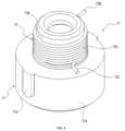
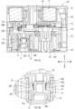
図1A,1B,1Cに示す印刷システム1は、印刷用カセット10と、印刷装置100とを備える。印刷システム1は、テープ状の印刷媒体に印刷を行う装置である。[1. First Embodiment]
[1-1. composition]
A
本実施形態では、出力ギア18の軸方向を上下方向とし、上下方向と垂直な方向のうち出力ギア18と入力スプール16とが並ぶ方向を前後方向とし、上下方向と前後方向との双方に垂直な方向を左右方向とする。 In this embodiment, the axial direction of the
<印刷用カセット>
印刷用カセット10は、印刷媒体を格納している。印刷用カセット10は、印刷装置100に着脱可能である。印刷用カセット10の交換により、印刷媒体の補給、及び印刷媒体の種類(例えば、色、材質等)の変更ができる。<Cassette for printing>
The
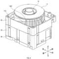
印刷用カセット10は、図2A,2B,2Cに示すように、後述する被印刷テープ、インクリボン等を格納するケース35を備える。印刷用カセット10の外形(つまり、ケース35の形状)は、上下方向に平行な辺と、前後方向に平行な辺と、左右方向に平行な辺とを有する直方体状である。 As shown in FIGS. 2A, 2B, and 2C, the
ケース35は、印刷装置100に対し下向きに装着されるように構成されている。ケース35は、第1蓋部31と、第1ケース部32と、第2ケース部33と、第2蓋部34とを有する。 The
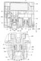
印刷用カセット10は、図3に示すように、被印刷テープロール11と、第1供給スプール12と、スペーサフィルム13A,13Bと、インクリボンロール14と、第2供給スプール15と、入力スプール16(回転スプールの一例)と、クラッチ17と、出力ギア18と、入力ギア19と、アイドルギア20と、を備える。 The
(被印刷テープロール)
被印刷テープロール11は、印刷が行われる被印刷テープを第1供給スプール12に巻回したものである。被印刷テープの表面には、後述する印刷装置100の印刷ヘッド102及びインクリボンによって印刷が行われる。(Printed tape roll)
The print-receiving
被印刷テープロール11の上下方向の外側には、被印刷テープロール11を挟むように2つのスペーサフィルム13A,13Bが配置されている。スペーサフィルム13A,13Bは、被印刷テープロール11と第1蓋部31との間と、被印刷テープロール11と第1ケース部32との間とに配置されている。 Two
(第1供給スプール)
第1供給スプール12は、回転軸心周りに回転可能である。第1供給スプール12は、後述する印刷装置100のプラテンローラ103による被印刷テープの搬送に伴って回転することで、被印刷テープを印刷ヘッド102に供給する。(First supply spool)
The
(インクリボンロール)
インクリボンロール14は、被印刷テープの印刷に用いられるインクリボンを第2供給
スプール15に巻回したものである。(ink ribbon roll)
The
インクリボンは、後述するヘッド開口33Bにおいて、被印刷テープと重ね合わされ、印刷ヘッド102による印刷に供される。印刷に使用されたインクリボンは、後述する入力スプール16に巻き取られる。 The ink ribbon is superimposed on the print tape at a
(第2供給スプール)
第2供給スプール15は、回転軸心周りに回転可能である。第2供給スプール15の回転軸心は、第1供給スプール12の回転軸心、つまり上下方向と平行である。第2供給スプール15は、第1回転方向に回転することで、インクリボンロール14からインクリボンを送り出す。(Second supply spool)
The
第2供給スプール15は、インクリボンの入力スプール16による巻き取りに伴って回転することで、インクリボンを印刷ヘッド102に供給する。また、第2供給スプール15の少なくとも一部は、上下方向において、被印刷テープロール11と重なる位置に配置されている。 The
(入力スプール)
入力スプール16は、回転軸心周りに回転可能である。入力スプール16の回転軸心は、第2供給スプール15の回転軸心と平行である。(input spool)
The
入力スプール16は、円筒状であり、内周面16Aで規定される中空部を有する。入力スプール16の内周面16Aにはスプライン歯16Bが設けられている。つまり、入力スプール16は内歯ギアである。スプライン歯16Bには、後述する印刷装置100の駆動シャフト105が連結される。入力スプール16は、駆動シャフト105によって回転され、インクリボンを巻き取る。 The
(クラッチ)
クラッチ17は、図4に示すように、バネホルダ71と、クラッチバネ72とを有する。バネホルダ71は、回転軸心周りに回転可能である。(clutch)
The clutch 17 has a
バネホルダ71は、第1円筒部71Aと、第2円筒部71Bと、突起71Cとを有する。第2円筒部71Bは、第1円筒部71Aよりも外径が小さい。また、第2円筒部71Bの中心軸は、第1円筒部71Aの中心軸と同一直線上に配置されている。突起71Cは、第1円筒部71Aの外周面から第1円筒部71Aの径方向外側に突出している。 The
クラッチバネ72は、コイル部72Aと、第1係合部72Bと、第2係合部72Cとを有する。コイル部72Aは、第2円筒部71Bの外周面に螺旋状に巻回された線状体で構成されている。第1係合部72B及び第2係合部72Cは、それぞれ、コイル部72Aを形成している線状体の端部が第2円筒部71Bの径方向外側に突出することで構成されている。 The
図5A,5Bに示すように、クラッチ17は、第2供給スプール15の中空部に配置されている。クラッチ17の回転軸心は、第2供給スプール15の回転軸心と同一直線上に配置されている。 As shown in FIGS. 5A and 5B, clutch 17 is located in the hollow portion of
バネホルダ71の第2円筒部71B及びクラッチバネ72のコイル部72Aは、後述する第2ケース部33の複数の凸部33Fの内側に配置されている。クラッチバネ72の第1係合部72B及び第2係合部72Cは、凸部33Fに係合している。 The second
バネホルダ71の突起71C(図4参照)は、第2供給スプール15の内周面に形成された溝に係合している。そのため、バネホルダ71は、第2供給スプール15と共に第2供給スプール15の回転軸心周りに回転する。 A
第2供給スプール15の回転には、バネホルダ71の第2円筒部71Bとクラッチバネ72のコイル部72Aとの間の摺動摩擦によって抵抗が付される。つまり、クラッチ17は、インクリボンロール14に回転抵抗を付している。インクリボンを送り出す(つまり巻き取る)ためのトルクは、クラッチ17の回転抵抗によって設定することができる。 Rotation of the
クラッチバネ72のコイル部72Aは、第1回転方向にバネホルダ71が回転した際に拡径し、第1回転方向とは反対の第2回転方向にバネホルダ71が回転した際に縮径するようにバネホルダ71に巻回されている。 The
したがって、インクリボンが引き出されることによって第2供給スプール15が第1回転方向に回転すると、コイル部72Aが拡径するため、コイル部72Aと第2円筒部71Bとの間の摺動摩擦が小さくなる。その結果、第2供給スプール15の回転抵抗が小さくなる。 Therefore, when the
一方、第2供給スプール15の回転が小さくなると、コイル部72Aが縮径するため、第2供給スプール15の回転抵抗が大きくなる。第2供給スプール15の回転が停止すると、コイル部72Aと第2円筒部71Bとの間の摺動摩擦が初期状態に戻る。 On the other hand, when the rotation of the
(出力ギア)
図3に示す出力ギア18は、被印刷テープを搬送するための駆動力を外部に出力するための出力部である。出力ギア18は、後述する入力ギア19と駆動連結されている。出力ギア18は、印刷装置100のプラテンギア104を介して、プラテンローラ103に駆動力を伝達する。(output gear)
The
出力ギア18は、回転軸心周りに回転する円盤と、円盤の上下方向と平行な面に設けられた歯とを有する外歯ギアである。出力ギア18の円盤の上下方向と垂直な一方の面(つまり上面)は、上下方向においてケース35の後述するカバー部32Bと対向している。円盤の上下方向と垂直な他方の面(つまり下面)の一部は、上下方向においてケース35と対向していない。 The
出力ギア18は、ヘッド開口33Bに一部が露出しており、一部がケース35の外に位置している。出力ギア18は、印刷用カセット10が印刷装置100のカセット装着部101に装着された状態で、ヘッド開口33Bにおいてプラテンギア104に係合する。 The
被印刷テープロール11、出力ギア18、及びインクリボンロール14(つまり第2供給スプール15)は、上下方向において、被印刷テープロール11、出力ギア18、及びインクリボンロール14の順に並んで配置されている。つまり、出力ギア18は、上下方向において、被印刷テープロール11とインクリボンロール14との間に位置する。 The print-receiving
(入力ギア)
図3に示すように、入力ギア19は、後述するアイドルギア20を介して出力ギア18と間接的に係合し、駆動力を出力ギア18に伝達するための入力部である。(input gear)
As shown in FIG. 3 , the
印刷用カセット10が後述する印刷装置100のカセット装着部101に装着された状態で、入力ギア19は駆動シャフト105と係合する。入力ギア19には、駆動シャフト105を介して、印刷装置100の駆動源からの駆動力が入力される。 The
入力ギア19は、外歯ギア19Aと、円筒状の内歯ギア19Bとを有する。外歯ギア19Aの全体及び内歯ギア19Bの全体は、それぞれ、ケース35に収納されている。つまり、入力ギア19の全体は、ケース35に収納されている。 The
外歯ギア19Aは、内歯ギア19Bに入力された駆動力によって内歯ギア19Bと一体回転する。内歯ギア19Bは、外歯ギア19Aの下面に固定されると共に、内周面にスプライン歯を有する。 The
入力ギア19の回転軸心(つまり、外歯ギア19Aの回転軸心及び内歯ギア19Bの回転軸心)は、入力スプール16の回転軸心と同一線上に配置されている。入力スプール16、入力ギア19、及び被印刷テープロール11は、上下方向において、入力スプール16、入力ギア19、及び被印刷テープロール11の順に並んで配置されている。 The rotation axis of the input gear 19 (that is, the rotation axis of the
つまり、入力ギア19は、上下方向において、入力スプール16と被印刷テープロール11との間に位置する。また、入力ギア19の少なくとも一部は、上下方向において、被印刷テープロール11と重なる位置に配置されている。 That is, the
入力ギア19の回転軸心は、入力スプール16の中空部を通る。つまり、駆動シャフト105が入力スプール16と入力ギア19とに同時に挿通される。その結果、入力ギア19は、入力スプール16と直接連結はされていないが、入力スプール16と共通の駆動源(つまり駆動シャフト105)によって回転される。 The rotation axis of the
(アイドルギア)
アイドルギア20は、入力ギア19と出力ギア18とに駆動連結され(つまり係合し)、入力ギア19に入力された駆動力を出力ギア18に伝達する伝達ギアである。(idle gear)
The
アイドルギア20は、入力ギア19に係合した第1ギア20Aと、出力ギア18に係合した第2ギア20Bとが同軸上に並んで配置された段ギアである。第2ギア20Bは、第1ギア20Aよりも径が小さい。 The
第2ギア20Bは、上下方向において、第1ギア20Aよりも被印刷テープロール11に近い位置(つまり上方)に配置されている。アイドルギア20は、入力ギア19に入力された駆動力を減速させる減速機構を構成している。 The
(ケース)
第1蓋部31は、印刷用カセット10の上端部を構成している。第1ケース部32は、第1蓋部31の下側に配置され、第1蓋部31と上下方向に連結されている。第2ケース部33は、第1ケース部32の下側に配置され、第1ケース部32と上下方向に連結されている。第2蓋部34は、印刷用カセット10の下端部を構成している。第2蓋部34は、第2ケース部33と上下方向に連結されている。(Case)
The
第1蓋部31と第1ケース部32とは、被印刷テープロール11を収納している。つまり、被印刷テープロール11は、第1蓋部31と第1ケース部32とで囲まれた空間に配置されている。 The
第2蓋部34と第2ケース部33とは、インクリボンロール14、第2供給スプール15、及び入力スプール16を収納している。つまり、インクリボンロール14、第2供給スプール15、及び入力スプール16は、第2蓋部34と第2ケース部33とで囲まれた空間に配置されている。 The
第1ケース部32と第2ケース部33とは、互いに連結されている。出力ギア18の一部、入力ギア19、及びアイドルギア20は、第1ケース部32と第2ケース部33とで囲まれた空間に配置されている。 The
第1ケース部32は、第1側壁32Aと、カバー部32Bと、第1ガイド32Cと、第1軸部32Dと、第2軸部32Eと、第3軸部32Fと、内壁32Gとを有する。第1側壁32Aは、印刷用カセット10の上下方向と平行な側面を構成する。 The
カバー部32Bは、上下方向と垂直な表面を有する部位である。カバー部32Bは、上下方向において出力ギア18と重なる位置に配置されている。本実施形態では、カバー部32Bは、第1側壁32Aの下端部と連続して設けられ、第1ケース部32の右前方の角部に配置されている。 The
出力ギア18、カバー部32B、及び被印刷テープロール11は、上下方向において、出力ギア18、カバー部32B、及び被印刷テープロール11の順に並んで配置されている。また、上述のように、出力ギア18の上面の全領域は、カバー部32Bによって覆われている。 The
第1ガイド32Cは、図6に示すように、被印刷テープロール11から引き出された被印刷テープ11Aが巻き掛けられる部位である。第1ガイド32Cは、被印刷テープロール11の周方向に沿って離間して配置された複数の板状のリブを有する。複数のリブは、被印刷テープロール11の径方向に突出しており、下方に向かうほど突出量(つまり板幅)が大きくなっている。 As shown in FIG. 6, the
図3に示す第1軸部32Dは、出力ギア18を上下方向と平行な回転軸心周りに回転可能に支持する。第2軸部32Eは、入力ギア19を上下方向と平行な回転軸心周りに回転するように軸支する。第3軸部32Fは、アイドルギア20を上下方向と平行な回転軸心周りに回転するように軸支する。第1軸部32D、第2軸部32E及び第3軸部32Fは、内壁32Gから突出している。 The
第2ケース部33は、第2側壁33Aと、ヘッド開口33Bと、排出口33Cと、第2ガイド33Dと、突出部33Eと、複数の凸部33Fとを有する。第2側壁33Aは、印刷用カセット10の上下方向と平行な側面を構成する。 The
ヘッド開口33Bは、第2側壁33Aの一部を切り欠いた部位である。ヘッド開口33Bは、印刷用カセット10が印刷装置100に装着された状態で、印刷ヘッド102が下方から挿入されることで、内部に印刷ヘッド102が配置される空間である。ヘッド開口33Bは、印刷用カセット10の下方に開口している。 The
第2ガイド33Dは、第1ガイド32Cを通過した被印刷テープ11Aが巻き掛けられる部位である。第2ガイド33Dは、第1ガイド32Cと同様に、インクリボンロール14の周方向に沿って離間して配置された複数の板状のリブを有する。複数のリブは、インクリボンロール14の径方向に突出しており、下方に向かうほど突出量(つまり板幅)が小さくなる。 The
突出部33Eは、上下方向において出力ギア18と重なる位置に配置されている。突出部33Eは、出力ギア18の下側(つまり、出力ギア18を挟んでカバー部32Bとは反対側)に配置されている。 The projecting
印刷装置100の印刷ヘッド102は、突出部33Eよりも下方の領域に挿入される。そのため、印刷用カセット10が印刷装置100のカセット装着部101に装着された状態で、出力ギア18は、印刷ヘッド102よりもカセット装着部101への印刷用カセット10の装着方向における上流側(つまり上方)に配置される。 The
複数の凸部33Fは、図5Aに示すように、クラッチ17の第2円筒部71B及びコイル部72Aを囲うように、クラッチ17の第2円筒部71Bの周方向に沿って配置されている。クラッチバネ72の第1係合部72B及び第2係合部72Cは、それぞれ、複数の凸部33Fの間に挿入されている。 5A, the plurality of
クラッチ17の第1円筒部71Aの内部には、第2蓋部34に設けられた第4軸部34Aが挿入されている。第2供給スプール15は、第1円筒部71Aを介して、第4軸部34Aによって軸回転可能に軸支されている。 A
図7に示すように、ヘッド開口33Bにおいて、被印刷テープ11A及びインクリボン14Aが左右方向に架け渡される。印刷後の被印刷テープ11Aは、排出口33Cから印刷システム1の外部に排出される。 As shown in FIG. 7, the print-receiving
図8A,8B,8C,8Dに示すように、第1ガイド32C及び第2ガイド33Dは、被印刷テープロール11を構成する被印刷テープ11Aを第1ケース部32から第2ケース部33に送る通路を構成している。 As shown in FIGS. 8A, 8B, 8C, and 8D, the
具体的には、図8Aに示すように、被印刷テープロール11から引き出された被印刷テープ11Aは、螺旋を描くように第1ガイド32Cに被印刷テープロール11の径方向外側から当接しながら第1ケース部32内で下後方に向かって搬送される。被印刷テープ11Aは、さらに図8Bに示すように、第1ケース部32と第2ケース部33との連結部分を上下方向に跨ぎつつ、左下方に向かって搬送される。 Specifically, as shown in FIG. 8A, the print-receiving
第2ケース部33に到達した被印刷テープ11Aは、図8Cに示すように、第2ガイド33Dに径方向外側から当接しながら下前方に向かって搬送される。印刷用カセット10の下端部に到達した被印刷テープ11Aは、図8Dに示すように、ヘッド開口33Bを通過して排出口33Cから排出される。 As shown in FIG. 8C, the print-receiving
<印刷装置>
印刷装置100は、図1Bに示すように、カセット装着部101と、印刷ヘッド102と、プラテンローラ103と、プラテンギア104と、駆動源(図示省略)と、駆動シャフト105と、可動部107とを備える。<Printing device>
As shown in FIG. 1B, the
(カセット装着部)
カセット装着部101は、印刷用カセット10が駆動シャフト105の回転軸心の軸方向(つまり上下方向)に装着可能な凹部である。カセット装着部101は、印刷用カセット10の位置決め機能を有する。(Cassette mounting part)
The
(印刷ヘッド)
印刷ヘッド102は、印刷用カセット10が保持する被印刷テープに印刷するための装置である。(print head)
The
印刷ヘッド102は、カセット装着部101の内部に配置されている。印刷ヘッド102は、印刷用カセット10が印刷装置100に装着された状態で、ヘッド開口33Bにおいて、被印刷テープ及びインクリボンと前後方向に重なる位置に配置される。 The
印刷ヘッド102は、個別に発熱が制御される複数の発熱素子を有する。後述するプラテンローラ103によってヘッド開口33Bに搬送された被印刷テープは、インクリボンを介して発熱素子が発熱した印刷ヘッド102に押し付けられる。これにより、インクリボンの表面に配置されたインクの一部が被印刷テープに転写され、被印刷テープに文字、記号等が印刷される。 The
(プラテンローラ)
プラテンローラ103は、出力ギア18から伝達される駆動力によって被印刷テープを印刷用カセット10内から外部に向けて搬送するためのローラである。プラテンローラ103の回転軸心は、上下方向と平行である。(platen roller)
The
プラテンローラ103は、カセット装着部101の内部において、印刷ヘッド102と対向するように配置されている。プラテンローラ103は、ヘッド開口33Bにおいて被印刷テープに当接し、被印刷テープを印刷ヘッド102に押し当てる。 The
(プラテンギア)
プラテンギア104は、プラテンローラ103に駆動連結され、出力ギア18と係合する外歯ギアである。(Platen gear)
The
本実施形態では、プラテンギア104の回転軸心は、プラテンローラ103の回転軸心と同一線上に配置されている。また、プラテンギア104は、プラテンローラ103よりも印刷用カセット10のカセット装着部101への装着方向における上流側(つまり上方)に配置されている。 In this embodiment, the rotation axis of the
(可動部)
可動部107は、上下方向と垂直な面内で揺動可能なように筐体110に取り付けられている。プラテンローラ103及びプラテンギア104は、可動部107に支持されることにより、筐体110に対して揺動可能に構成されている。(movable part)
The
プラテンローラ103及びプラテンギア104は、可動部107の揺動により、図10Aに示す印刷用カセット10と離間した位置と、図10Bに示すプラテンギア104が出力ギア18に係合した位置との間で揺動可能である。 The
(駆動シャフト)
図1Bに示す駆動シャフト105は、入力スプール16に挿入されると共に入力ギア19に係合し、入力スプール16と入力ギア19とを回転させるためのシャフトである。駆動シャフト105は、入力スプール16のスプライン歯16B及び入力ギア19の内歯ギア19Bと係合する外歯を有する。(drive shaft)
A
駆動シャフト105は、カセット装着部101の内部に配置されている。駆動シャフト105の回転軸心は、上下方向と平行である。駆動シャフト105は、駆動源(例えばモータ)によって回転軸心を中心に回転可能である。駆動源は、印刷用カセット10に入力される駆動力を発生させる。 The
印刷用カセット10がカセット装着部101に装着された状態で、駆動シャフト105の少なくとも一部は、入力スプール16の内部に配置される。この状態では、駆動シャフト105が入力ギア19に係合すると共に、プラテンギア104が出力ギア18に係合する。 At least a portion of the
具体的には、駆動シャフト105を印刷用カセット10の入力スプール16及び入力ギア19に挿入し、プラテンローラ103及びプラテンギア104を印刷用カセット10のヘッド開口33Bに向けて揺動させることで、印刷用カセット10が印刷装置100に装着される。 Specifically, by inserting the
印刷用カセット10が装着された状態で駆動シャフト105により入力ギア19が回転されることで出力ギア18が回転され、出力ギア18の回転によりプラテンギア104が回転し、プラテンギア104の回転によりプラテンローラ103が回転する。 When the
図10Bに示すように、印刷用カセット10がカセット装着部101に装着された状態で、プラテンローラ103が被印刷テープを搬送することによって印刷用カセット10に発生する駆動シャフト105周りのモーメントの方向M1は、駆動シャフト105の駆動回転方向Sと同じ向きである。 As shown in FIG. 10B, the direction of the moment around the
一方、印刷用カセット10がカセット装着部101に装着された状態で、出力ギア18がプラテンギア104から受ける反力によって印刷用カセット10に発生する駆動シャフト105周りのモーメントの方向M2は、駆動シャフト105の駆動回転方向Sと逆向きである。 On the other hand, when the
[1-2.効果]
以上詳述した実施形態によれば、以下の効果が得られる。
(1a)印刷装置100の駆動源からの駆動力が印刷用カセット10内の入力ギア19及び出力ギア18を介してプラテンローラ103に伝達される。[1-2. effect]
According to the embodiment detailed above, the following effects are obtained.
(1a) A driving force from the driving source of the
つまり、印刷装置100に印刷用カセット10が装着された状態で初めてプラテンローラ103に駆動力が伝達される。そのため、印刷用カセット10が装着されていない状態におけるプラテンローラ103の不測の回転を抑制できる。 That is, the driving force is transmitted to the
(1b)入力ギア19が駆動シャフト105の外歯と係合する内歯ギア19Bを有し、出力ギア18及びプラテンギア104とが互いに係合する外歯ギアであることで、印刷用カセット10及び印刷装置100におけるギア列の配置の自由度を高められる。 (1b) The
(1c)1つの駆動シャフト105から、入力スプール16の回転軸心の軸方向(つまり駆動シャフト105の挿入方向)の異なる位置において入力スプール16と入力ギア19とに駆動力を伝達することができる。そのため、駆動シャフト105の挿入方向と垂直な方向(つまり前後方向及び左右方向)における印刷用カセット10のサイズの大型化を抑制しながら、入力スプール16と入力ギア19との双方に駆動力を入力できる。 (1c) Driving force can be transmitted from one
(1d)プラテンギア104がプラテンローラ103よりも印刷用カセット10のカセット装着部101への装着方向における上流側に配置されることで、出力ギア18と印刷ヘッド102との干渉を避けることができる。その結果、ヘッド開口33Bの拡大に伴うカセットの大型化を抑制できる。 (1d) By arranging the
(1e)プラテンローラ103が被印刷テープを搬送することによる駆動シャフト105周りのモーメントの方向M1が、出力ギア18がプラテンギア104から受ける反力による駆動シャフト105周りのモーメントの方向M2と逆向きであることで、印刷装置100内で印刷用カセット10が回転することを抑制できる。 (1e) The direction M1 of the moment around the
(1f)クラッチ17によって、インクリボンの巻取トルクを調整することができる。そのため、同じ形状の印刷用カセット10において、幅、厚み、材質等の異なるインクリ
ボンを配置することができる。(1f) The clutch 17 can adjust the winding torque of the ink ribbon. Therefore, ink ribbons having different widths, thicknesses, materials, etc. can be arranged in the
[2.第2実施形態]
[2-1.構成]
図11A,11Bに示す印刷システム1Aは、印刷用カセット10Aと、印刷装置100Aとを備える。[2. Second Embodiment]
[2-1. composition]
A
<印刷用カセット>
印刷用カセット10Aは、第1実施形態の印刷用カセット10に、図12に示すラミネートテープロール21と、追加スプール22と、追加ギア23と、ピンチローラ24と、第2クラッチ17Aを追加したものである。<Cassette for printing>
A
また、印刷用カセット10Aは、第1実施形態の印刷用カセット10における入力スプール16、第1蓋部31、第1ケース部32、第2ケース部33及び第2蓋部34を、それぞれ、第3供給スプール25、第1蓋部36、第1ケース部37、第2ケース部38及び第2蓋部39に置き換えたものである。 Further, the
第3供給スプール25は、スプライン歯16Bを有しない点を除いて、入力スプール16と同じものである。第1蓋部36、第1ケース部37、第2ケース部38及び第2蓋部39は、それぞれ、第1蓋部31、第1ケース部32、第2ケース部33及び第2蓋部34を左右方向に延伸させたものである。印刷用カセット10Aのその他の構成は、以下に説明する点を除き、第1実施形態の印刷用カセット10と同じであるため、説明を省略する。 The
ラミネートテープロール21は、被印刷テープの保護に用いられるラミネートテープを第3供給スプール25に巻回したものである。ラミネートテープは、印刷ヘッド102によって印刷が行われた被印刷テープに貼り合わされる接着面を有する。 The
追加スプール22は、回転軸心周りに回転可能である。追加スプール22の回転軸心は、第2供給スプール15の回転軸心(つまり上下方向)と平行である。追加スプール22は、後述する追加ギア23の回転によりインクリボンを巻き取る巻取スプールである。 The
追加ギア23は、追加スプール22に連結されると共に、アイドルギア20に係合している。追加ギア23は、入力ギア19に入力された駆動力によって回転し、追加スプール22を回転させる。 The
追加ギア23は、外歯ギア23Aと、複数の凸部23Bと、軸部23Cとを有する。外歯ギア23Aは、上下方向と平行な回転軸心を有する。複数の凸部23Bは、軸部23Cを囲うように、軸部23Cの周面に沿って配置されている。複数の凸部23B及び軸部23Cは、外歯ギア23Aから下方に突出している。 The
ピンチローラ24は、後述する押圧ローラ106と共に、ラミネートテープを印刷後の被印刷テープに押し付ける。ピンチローラ24は、ヘッド開口33Bよりも被印刷テープの搬送方向の下流に配置されている。 The
第2クラッチ17Aは、入力ギア19を追加スプール22に駆動連結している。具体的には、第2クラッチ17Aは、入力ギア19と駆動連結された追加ギア23と、追加スプール22とを駆動連結している。第2クラッチ17Aは、クラッチ17と同様のバネホルダ71と、クラッチバネ72とを有している。 The second clutch 17</b>A drivingly connects the
図13A,13Bに示すように、第2クラッチ17Aの第2円筒部71B及びコイル部72Aは、追加ギア23の複数の凸部23Bの内側に配置されている。また、第2円筒部71Bの内部には、追加ギア23の軸部23Cが挿通されている。 As shown in FIGS. 13A and 13B, the second
第2クラッチ17Aの第1円筒部71Aは、追加スプール22の内周面に固定されている。第2クラッチ17Aの第1係合部及び第2係合部(図示省略)は、追加ギア23の複数の凸部23Bに係合している。 The first
第2クラッチ17Aの第1円筒部71Aの内部には、第2蓋部39に設けられた第5軸部39Aが挿入されている。追加スプール22は、第1円筒部71Aを介して、第5軸部39Aによって軸回転可能に軸支されている。 A
追加スプール22には、第2クラッチ17Aのバネホルダ71の第2円筒部71Bとクラッチバネ72のコイル部72Aとの間の摺動摩擦によって抵抗が付される。つまり、第2クラッチ17Aは、インクリボンの巻取スプールに回転抵抗を付している。インクリボンを巻き取るためのトルクは、第2クラッチ17Aの回転抵抗によって設定することができる。 Resistance is applied to the
また、本実施形態では、第1実施形態と同じクラッチ17によって、ラミネートテープロール21に回転抵抗が付されている。 Further, in the present embodiment, rotational resistance is applied to the
<印刷装置>
印刷装置100Aは、第1実施形態の印刷装置100に、図12に示される押圧ローラ106を追加したものである。印刷装置100Aのその他の構成は、以下に説明する点を除き、第1実施形態の印刷装置100と同じであるため、説明を省略する。<Printing device>
A
押圧ローラ106は、図14に示すように、可動部107に取り付けられ、プラテンローラ103及びプラテンギア104と共に揺動可能に構成されている。つまり、押圧ローラ106は、図15Aに示す印刷用カセット10Aと離間した位置と、図15Bに示すピンチローラ24と共に被印刷テープ及びラミネートテープを押圧する位置との間で揺動可能である。 As shown in FIG. 14, the
[2-2.効果]
以上詳述した実施形態によれば、以下の効果が得られる。
(2a)第1実施形態と同様の利点を有したまま、ラミネートテープによって被印刷テープの印刷内容を保護することができる。[2-2. effect]
According to the embodiment detailed above, the following effects are obtained.
(2a) It is possible to protect the printed contents of the print-receiving tape with the laminated tape while having the same advantages as in the first embodiment.
[3.他の実施形態]
以上、本開示の実施形態について説明したが、本開示は、上記実施形態に限定されることなく、種々の形態を採り得ることは言うまでもない。[3. Other embodiments]
Although the embodiments of the present disclosure have been described above, it is needless to say that the present disclosure is not limited to the above embodiments and can take various forms.
(3a)上記実施形態の印刷装置は、インクリボンを用いて印刷するものに限定されない。印刷装置は、被印刷テープとして帯状の感熱紙を用いて印刷を行ってもよい。また、印刷用カセットは、必ずしもインクリボンロールと第2供給スプールとを有しなくてもよい。 (3a) The printing apparatus of the above embodiments is not limited to printing using an ink ribbon. The printing apparatus may print using strip-shaped thermal paper as the print-receiving tape. Also, the printing cassette does not necessarily have an ink ribbon roll and a second supply spool.
例えば、図16に示す印刷用カセット10Bは、第1実施形態の印刷用カセット10において、被印刷テープロール11を感熱紙の被印刷テープロール51に置き換えると共に、インクリボンロール14をラミネートテープのラミネートテープロール52に置き換えたものである。 For example, in the
印刷用カセット10Bでは、ラミネートテープロール52は、第2実施形態の第3供給スプール25に巻回されている。また、印刷用カセット10Bは、第2実施形態のピンチローラ24を備える一方で、第2供給スプール15は備えない。 In the
(3b)上記実施形態の印刷用カセットにおいて、プラテンローラに駆動力を伝達する出力部は、ギアに限定されない。例えば、出力部として、ローラ又はスプールが用いられてもよい。また、駆動源からの駆動力が入力される入力部も、ギアに限定されない。例えば、入力部として、ローラ又はスプールが用いられてもよい。 (3b) In the printing cassette of the above embodiment, the output section that transmits driving force to the platen roller is not limited to gears. For example, a roller or spool may be used as the output section. Also, the input portion to which the driving force from the driving source is input is not limited to gears. For example, a roller or spool may be used as the input section.
(3c)第2実施形態の印刷用カセットにおいて、ラミネートテープが追加スプールに巻回されてもよい。 (3c) In the printing cassette of the second embodiment, the laminate tape may be wound around the additional spool.
例えば、図17に示す印刷用カセット10Cは、第2実施形態の印刷用カセット10Aにおいて、追加スプール22にラミネートテープのラミネートテープロール21を巻回したものである。印刷用カセット10Cは、第2実施形態の第3供給スプール25に代えて、第1実施形態の入力スプール16を備える。入力スプール16は、インクリボンの巻取スプールとして使用される。 For example, a
(3d)上記実施形態の印刷用カセットは、被印刷テープロール、出力ギア、及び被印刷テープの印刷又は保護に用いられる補助テープの補助テープロール(つまりインクリボンロール又はラミネートテープロール)が上下方向に並ぶものに限定されない。印刷用カセットにおいて、被印刷テープは、上下方向と垂直な方向において、補助テープロールと重なるように配置されてもよい。 (3d) In the printing cassette of the above embodiment, the printing tape roll, the output gear, and the auxiliary tape roll (that is, the ink ribbon roll or the laminate tape roll) of the auxiliary tape used for printing or protecting the printing tape are arranged vertically. is not limited to those listed in . In the printing cassette, the print-receiving tape may be arranged so as to overlap the auxiliary tape roll in a direction perpendicular to the vertical direction.
例えば、図18に示す印刷用カセット10Dは、第2実施形態の印刷用カセット10Aにおいて、第1蓋部36、第1ケース部37、第2ケース部38及び第2蓋部39に代えて、第1ケース部41、第2ケース部42及び蓋部43を用いたものである。 For example, a
第1ケース部41は、図12の第1ケース部37の左右方向の長さを調整したものから、内壁32Gよりも下側の部分を取り出したものである。第2ケース部42は、図12の第2ケース部38の左右方向の長さを調整したものである。蓋部43は、図12の第2蓋部39の左右方向の長さを調整したものである。 The
印刷用カセット10Dの第3供給スプール25には、ラミネートテープロール21に代えて被印刷テープロール11が巻回されている。インクリボンは、第2実施形態と同様に、追加スプール22によって巻き取られる。 Instead of the
さらに、印刷用カセット10Dにおいて、被印刷テープとして感熱紙を用いてもよい。この場合、インクリボンロール14、第2供給スプール15、追加スプール22及び追加ギア23は不要となり、印刷用カセット10Dは、ロールとして被印刷テープロール11のみを備える。 Furthermore, in the
(3e)上記実施形態の印刷用カセットは、2つ以上のアイドルギアを有してもよい。つまり、印刷用カセットは、入力ギアと係合する伝達ギア列を有してもよい。また、入力ギアと出力ギアとは、アイドルギアを介さずに直接係合してもよい。 (3e) The printing cassette of the above embodiment may have two or more idle gears. That is, the printing cassette may have a transmission gear train that engages the input gear. Also, the input gear and the output gear may be directly engaged without an idle gear.
(3f)上記実施形態における1つの構成要素が有する機能を複数の構成要素として分散させたり、複数の構成要素が有する機能を1つの構成要素に統合したりしてもよい。また、上記実施形態の構成の一部を省略してもよい。また、上記実施形態の構成の少なくと
も一部を、他の上記実施形態の構成に対して付加、置換等してもよい。なお、特許請求の範囲に記載の文言から特定される技術思想に含まれるあらゆる態様が本開示の実施形態である。(3f) The function of one component in the above embodiments may be distributed as multiple components, or the functions of multiple components may be integrated into one component. Also, part of the configuration of the above embodiment may be omitted. Also, at least a part of the configuration of the above embodiment may be added, replaced, etc. with respect to the configuration of the other above embodiment. It should be noted that all aspects included in the technical idea specified by the wording in the claims are embodiments of the present disclosure.
1…印刷システム、10…印刷用カセット、11…被印刷テープロール、
12…第1供給スプール、14…インクリボンロール、15…第2供給スプール、
16…入力スプール、17,17A…クラッチ、18…出力ギア、19…入力ギア、
19A…外歯ギア、19B…内歯ギア、20…アイドルギア、
21…ラミネートテープロール、22…追加スプール、23…追加ギア、
24…ピンチローラ、25…第3供給スプール、31…第1蓋部、
32…第1ケース部、33…第2ケース部、33B…ヘッド開口、34…第2蓋部、
35…ケース、71…バネホルダ、72…クラッチバネ、100…印刷装置、
101…カセット装着部、102…印刷ヘッド、103…プラテンローラ、
104…プラテンギア、105…駆動シャフト、107…可動部。DESCRIPTION OF
12... First supply spool, 14... Ink ribbon roll, 15... Second supply spool,
16... Input spool, 17, 17A... Clutch, 18... Output gear, 19... Input gear,
19A... external gear, 19B... internal gear, 20... idle gear,
21... Laminated tape roll, 22... Additional spool, 23... Additional gear,
24... pinch roller, 25... third supply spool, 31... first lid,
32... First case part, 33... Second case part, 33B... Head opening, 34... Second cover part,
35...Case, 71...Spring holder, 72...Clutch spring, 100...Printing device,
DESCRIPTION OF
104... Platen gear, 105... Drive shaft, 107... Movable part.
Claims (21)
Translated fromJapanese前記印刷ヘッドに対向するプラテンローラと、
駆動源と、
前記駆動源に駆動連結され、回転軸心周りに回転可能な駆動シャフトと、
前記プラテンローラに駆動連結されたプラテンギアと、
前記印刷ヘッド及び前記駆動シャフトが配置されたカセット装着部と、
を備え、
前記カセット装着部は、被印刷テープ、入力部、及び前記入力部と駆動連結された出力部を有する印刷用カセットが前記駆動シャフトの前記回転軸心の軸方向に装着可能であり、
前記印刷用カセットが前記カセット装着部に装着された状態で、前記駆動シャフトは前記入力部と係合し、前記プラテンギアは前記出力部と係合する、印刷装置。a print head;
a platen roller facing the print head;
a driving source;
a drive shaft drivingly connected to the drive source and rotatable about a rotation axis;
a platen gear drivingly connected to the platen roller;
a cassette mounting part in which the print head and the drive shaft are arranged;
with
the cassette mounting portion is capable of mounting a printing cassette having a printing tape, an input portion, and an output portion drivingly connected to the input portion in an axial direction of the rotation axis of the drive shaft;
The printing apparatus according to claim 1, wherein the drive shaft is engaged with the input section and the platen gear is engaged with the output section when the printing cassette is mounted in the cassette mounting section.
前記入力部は、内歯を有する、請求項1に記載の印刷装置。the drive shaft, the platen gear, and the output section each have external teeth;
2. The printing device of claim 1, wherein the input portion has internal teeth.
前記印刷用カセットが前記カセット装着部に装着された状態で、前記出力部が前記プラテンギアから受ける反力によって前記印刷用カセットに発生する前記駆動シャフト周りのモーメントの方向は、前記駆動シャフトの回転方向と逆である、請求項1から請求項5のいずれか1項に記載の印刷装置。The direction of the moment around the drive shaft generated in the printing cassette by the platen roller conveying the printing tape while the printing cassette is mounted in the cassette mounting portion is the direction of the moment of the driving shaft. is the same as the direction of rotation,
The direction of the moment around the drive shaft generated in the printing cassette by the reaction force that the output unit receives from the platen gear when the printing cassette is mounted in the cassette mounting unit is the rotational direction of the drive shaft. 6. A printing apparatus according to any preceding claim, vice versa.
被印刷テープと、
入力部と、
前記入力部と駆動連結された出力部と、
を備え、
前記カセット装着部に装着された状態で、前記入力部は前記駆動シャフトと係合し、前記出力部は前記プラテンギアと係合する、印刷用カセット。a print head, a platen roller facing the print head, a drive source, a drive shaft drivingly connected to the drive source and rotatable about a rotation axis, a platen gear drivingly connected to the platen roller, and the A printing cassette mountable in an axial direction of the rotation axis of the drive shaft in a printing apparatus comprising a print head and a cassette mounting portion in which the drive shaft is arranged,
a printable tape;
an input unit;
an output unit drivingly connected to the input unit;
with
A printing cassette, wherein the input portion engages the drive shaft and the output portion engages the platen gear when mounted in the cassette mounting portion.
前記入力部は、第1内歯ギアを有する、請求項8に記載の印刷用カセット。The output section has an external gear,
9. The printing cassette of claim 8, wherein the input portion has a first internal gear.
前記回転スプールの回転軸心と前記第1内歯ギアの回転軸心とは同一線上に位置する、請求項9に記載の印刷用カセット。Equipped with a rotating spool,
10. The printing cassette according to claim 9, wherein the rotational axis of said rotary spool and the rotational axis of said first internal gear are located on the same line.
前記出力部の一部は、前記ケースの外に位置する、請求項8から請求項11のいずれか1項に記載の印刷用カセット。further comprising a case in which at least a portion of the print-receiving tape, the entire input section, and at least a portion of the output section are accommodated;
12. A printing cassette according to any one of claims 8 to 11, wherein a portion of said output section is positioned outside said case.
前記インクリボンを巻き取る巻取スプールと、
をさらに備え、
前記入力部は、前記巻取スプールに駆動連結される、請求項8から請求項12のいずれか1項に記載の印刷用カセット。an ink ribbon;
a winding spool for winding the ink ribbon;
further comprising
13. A printing cassette as claimed in any one of claims 8 to 12, wherein the input is drivingly connected to the take-up spool.
前記ケースに少なくとも一部が収納される被印刷テープと、
第1内歯ギアと第1外歯ギアとを有する第1ギアと、
前記第1外歯ギアと係合する伝達ギア又は伝達ギア列と、
前記伝達ギア又は前記伝達ギア列と係合する第2外歯ギアを有する第2ギアと、
を備え、
前記第1内歯ギアの全体は、前記ケースに収納され、
前記第2外歯ギアの一部は、前記ケースの外に位置する、印刷用カセット。a case;
a print-receiving tape at least partially housed in the case;
a first gear having a first internal gear and a first external gear;
a transmission gear or transmission gear train that engages with the first external gear;
a second gear having a second external gear that engages with the transmission gear or the transmission gear train;
with
The entire first internal gear is housed in the case,
A printing cassette, wherein a portion of the second external gear is located outside the case.
前記回転スプールの回転軸心と前記第1内歯ギアの回転軸心とは同一線上に位置する、請求項16又は請求項17に記載の印刷用カセット。Equipped with a rotating spool,
18. A printing cassette according to claim 16 or 17, wherein the rotation axis of said rotary spool and the rotation axis of said first internal gear are located on the same line.
前記インクリボンを巻き取る巻取スプールと、
をさらに備え、
前記第1ギアは、前記巻取スプールに駆動連結される、請求項16から請求項19のいずれか1項に記載の印刷用カセット。an ink ribbon;
a winding spool for winding the ink ribbon;
further comprising
20. The printing cassette of any one of claims 16-19, wherein the first gear is drivingly connected to the take-up spool.
Priority Applications (11)
| Application Number | Priority Date | Filing Date | Title |
|---|---|---|---|
| JP2019178163AJP7322638B2 (en) | 2019-09-30 | 2019-09-30 | Printer and cassette for printing |
| EP20871133.3AEP4019261B1 (en) | 2019-09-30 | 2020-09-15 | Printing device and printing cassette |
| CN202080067936.XACN114502384B (en) | 2019-09-30 | 2020-09-15 | Printing apparatus and tape cassette for printing |
| CN202411281109.7ACN119159918A (en) | 2019-09-30 | 2020-09-15 | Printing device and printing tape cassette |
| EP25195522.5AEP4628439A2 (en) | 2019-09-30 | 2020-09-15 | Printer and printing cassette |
| PCT/JP2020/034877WO2021065477A1 (en) | 2019-09-30 | 2020-09-15 | Printing device and printing cassette |
| CN202411281125.6ACN119078382A (en) | 2019-09-30 | 2020-09-15 | Printing device and printing tape cassette |
| CA3156251ACA3156251A1 (en) | 2019-09-30 | 2020-09-15 | Printer and printing cassette |
| US17/705,275US12214586B2 (en) | 2019-09-30 | 2022-03-26 | Printer and printing cassette |
| JP2023121497AJP7635803B2 (en) | 2019-09-30 | 2023-07-26 | Printing Cassette |
| JP2025020966AJP2025065476A (en) | 2019-09-30 | 2025-02-12 | Printing Cassette |
Applications Claiming Priority (1)
| Application Number | Priority Date | Filing Date | Title |
|---|---|---|---|
| JP2019178163AJP7322638B2 (en) | 2019-09-30 | 2019-09-30 | Printer and cassette for printing |
Related Child Applications (1)
| Application Number | Title | Priority Date | Filing Date |
|---|---|---|---|
| JP2023121497ADivisionJP7635803B2 (en) | 2019-09-30 | 2023-07-26 | Printing Cassette |
Publications (2)
| Publication Number | Publication Date |
|---|---|
| JP2021053875A JP2021053875A (en) | 2021-04-08 |
| JP7322638B2true JP7322638B2 (en) | 2023-08-08 |
Family
ID=75271973
Family Applications (3)
| Application Number | Title | Priority Date | Filing Date |
|---|---|---|---|
| JP2019178163AActiveJP7322638B2 (en) | 2019-09-30 | 2019-09-30 | Printer and cassette for printing |
| JP2023121497AActiveJP7635803B2 (en) | 2019-09-30 | 2023-07-26 | Printing Cassette |
| JP2025020966APendingJP2025065476A (en) | 2019-09-30 | 2025-02-12 | Printing Cassette |
Family Applications After (2)
| Application Number | Title | Priority Date | Filing Date |
|---|---|---|---|
| JP2023121497AActiveJP7635803B2 (en) | 2019-09-30 | 2023-07-26 | Printing Cassette |
| JP2025020966APendingJP2025065476A (en) | 2019-09-30 | 2025-02-12 | Printing Cassette |
Country Status (6)
| Country | Link |
|---|---|
| US (1) | US12214586B2 (en) |
| EP (2) | EP4628439A2 (en) |
| JP (3) | JP7322638B2 (en) |
| CN (3) | CN119078382A (en) |
| CA (1) | CA3156251A1 (en) |
| WO (1) | WO2021065477A1 (en) |
Families Citing this family (2)
| Publication number | Priority date | Publication date | Assignee | Title |
|---|---|---|---|---|
| JP2024056471A (en)* | 2022-10-11 | 2024-04-23 | ブラザー工業株式会社 | Printing cassette and printing device |
| JP2024056475A (en)* | 2022-10-11 | 2024-04-23 | ブラザー工業株式会社 | Printing Cassette |
Citations (5)
| Publication number | Priority date | Publication date | Assignee | Title |
|---|---|---|---|---|
| JP2000006504A (en) | 1998-06-24 | 2000-01-11 | Casio Comput Co Ltd | Tape winding device |
| JP2011046142A (en) | 2009-08-28 | 2011-03-10 | Brother Industries Ltd | Tape cassette and printer |
| JP2012158175A (en) | 2012-03-12 | 2012-08-23 | Brother Industries Ltd | Tape cassette and tape printer |
| JP2012236307A (en) | 2011-05-11 | 2012-12-06 | Fujicopian Co Ltd | Ink ribbon cassette of printing apparatus |
| JP2015182318A (en) | 2014-03-24 | 2015-10-22 | セイコーエプソン株式会社 | Tape cartridge and tape printer |
Family Cites Families (94)
| Publication number | Priority date | Publication date | Assignee | Title |
|---|---|---|---|---|
| SE364584B (en) | 1970-04-13 | 1974-02-25 | Canon Kk | |
| JPS5036734B1 (en) | 1970-04-13 | 1975-11-27 | ||
| US3672603A (en) | 1970-06-26 | 1972-06-27 | Cartridge Television Inc | Tape cartridge |
| US3804227A (en) | 1972-05-03 | 1974-04-16 | Scm Corp | Typewriter ribbon cartridge |
| US3948382A (en) | 1973-01-29 | 1976-04-06 | The Singer Company | Data terminal printing assembly |
| US4034935A (en) | 1975-11-19 | 1977-07-12 | Xerox Corporation | Dual level ribbon cartridge |
| CA1119549A (en) | 1978-01-30 | 1982-03-09 | Collier M. Miller | Ribbon cartridge drive |
| US4252450A (en) | 1978-10-03 | 1981-02-24 | Xerox Corporation | Ribbon drive with spring-loaded idler |
| US4397574A (en) | 1979-10-29 | 1983-08-09 | Ncr Corporation | Reloadable ribbon cassette |
| GB2064476B (en) | 1979-11-29 | 1983-08-10 | Itt Creed | Ink ribbon cassette |
| NL8200181A (en) | 1981-01-31 | 1982-08-16 | Victor Company Of Japan | REGISTER AND / OR REPRODUCER. |
| US4402619A (en) | 1981-03-30 | 1983-09-06 | Kroy, Inc. | Printing apparatus and printing cartridge therefor |
| JPS58122887A (en) | 1982-01-18 | 1983-07-21 | Silver Seiko Ltd | Motor driver for typewriter |
| JPS58141479A (en) | 1982-02-15 | 1983-08-22 | Canon Inc | Cassette |
| JPS58175949U (en) | 1982-05-20 | 1983-11-25 | 大和製衡株式会社 | label printer |
| FR2528929B1 (en) | 1982-06-17 | 1988-04-08 | Sagem | IMPROVEMENTS IN MECHANICAL DEVICES FOR SELECTIVE DRIVING OF AT LEAST TWO SHAFTS DRIVEN FROM A SINGLE DRIVING SHAFT, IN PARTICULAR FOR THE LONGITUDINAL MOVEMENT OF AN INK RIBBON IN A PRINTING MACHINE |
| JPS5995180A (en) | 1982-11-22 | 1984-06-01 | Matsushita Electric Ind Co Ltd | ink ribbon cassette |
| US4490059A (en) | 1983-05-04 | 1984-12-25 | Wordex | Ribbon metering device |
| JPS608072U (en) | 1983-06-30 | 1985-01-21 | アルプス電気株式会社 | printer |
| US4856921A (en) | 1983-06-28 | 1989-08-15 | Alps Electric Co., Ltd. | Rotary wheel printer |
| JPS609657U (en) | 1983-07-01 | 1985-01-23 | アルプス電気株式会社 | printer |
| DE3424045A1 (en) | 1983-06-30 | 1985-01-03 | Alps Electric Co., Ltd., Tokio/Tokyo | TYPE WHEEL PRINTER |
| JPS6036255U (en) | 1983-08-22 | 1985-03-13 | 日本電産コパル株式会社 | Thermal transfer serial printer |
| JPS6046254U (en) | 1983-09-06 | 1985-04-01 | アルプス電気株式会社 | ribbon cassette |
| JPS6048456U (en) | 1983-09-12 | 1985-04-05 | 株式会社東芝 | thermal transfer printer |
| JPH0227613B2 (en) | 1984-03-08 | 1990-06-19 | Teraoka Seiko Kk | DENSHIHAKARY OPURINTA |
| US4598780A (en) | 1984-03-02 | 1986-07-08 | Teraoka Seiko Co., Ltd. | Electronic scale printer |
| JPS60224571A (en) | 1984-04-20 | 1985-11-08 | Canon Inc | Transfer recording device |
| US4668961A (en) | 1984-04-20 | 1987-05-26 | Canon Kabushiki Kaisha | Recording apparatus |
| JPS61154877A (en) | 1984-12-27 | 1986-07-14 | Matsushita Electric Ind Co Ltd | Ribbon cassette |
| JPH0761729B2 (en) | 1985-10-30 | 1995-07-05 | 株式会社リコー | Ribbon cassette for printer |
| JPS63156762U (en) | 1987-04-02 | 1988-10-14 | ||
| US4832514A (en) | 1988-02-01 | 1989-05-23 | Kroy Inc. | Thermal transfer device and tape-ribbon cartridge therefor |
| JPH029562U (en) | 1988-06-22 | 1990-01-22 | ||
| JPH026173A (en) | 1988-06-27 | 1990-01-10 | Canon Inc | ribbon feeding device |
| JPH0211379A (en) | 1988-06-30 | 1990-01-16 | Canon Inc | Ink ribbon cassette |
| JPH0211380A (en) | 1988-06-30 | 1990-01-16 | Canon Inc | Ink ribbon cassette |
| US5099378A (en) | 1989-08-24 | 1992-03-24 | Minnesota Mining And Manufacturing Company | Carrier with external interlock for videocassette |
| IT218846Z2 (en) | 1989-11-16 | 1992-11-05 | Incas Holding Spa | NOTARBARTOLO & GERVASI |
| US5234179A (en) | 1990-02-20 | 1993-08-10 | Minnesota Mining And Manufacturing Company | Videotape adaptor for use with a cartridge |
| JPH03284973A (en) | 1990-04-02 | 1991-12-16 | Canon Inc | Ribbon cassette and recording device using same cassette |
| JPH04152176A (en) | 1990-10-16 | 1992-05-26 | Nec Corp | Ink ribbon cassette for printer |
| JPH0553956A (en) | 1991-08-29 | 1993-03-05 | Mitsubishi Electric Corp | System for supporting constitution of computer communication network |
| JPH0541834U (en) | 1991-11-11 | 1993-06-08 | フジコピアン株式会社 | Ink ribbon cassette |
| JPH0553956U (en) | 1991-12-24 | 1993-07-20 | 日本電気ホームエレクトロニクス株式会社 | Ink ribbon cassette |
| US5325114A (en) | 1992-09-24 | 1994-06-28 | Pitney Bowes Inc. | Thermal printing postage meter system |
| JP2995314B2 (en)* | 1992-10-15 | 1999-12-27 | カシオ計算機株式会社 | Tape cassette and printing device |
| JP3341052B2 (en) | 1993-06-28 | 2002-11-05 | カシオ計算機株式会社 | Printing cassette |
| JP2831237B2 (en) | 1993-07-19 | 1998-12-02 | 富士通アイソテック株式会社 | Ink ribbon cassette |
| US5411339A (en)* | 1993-12-09 | 1995-05-02 | Kroy, Inc. | Portable printer and cartridge therefor |
| US5435657A (en) | 1993-12-28 | 1995-07-25 | Smith Corona Corporation | Label printer and tape and ink ribbon cartridge for use therein |
| JPH07276755A (en) | 1994-04-06 | 1995-10-24 | Casio Comput Co Ltd | Printing cassette and printing device |
| JPH07276757A (en) | 1994-04-11 | 1995-10-24 | Fujicopian Co Ltd | Transfer ribbon cassette |
| US5619244A (en) | 1994-12-27 | 1997-04-08 | Pitney Bowes Inc. | Thermal ink cassette for a thermal printing device |
| JP3113532B2 (en) | 1994-12-28 | 2000-12-04 | アルプス電気株式会社 | Tape cassette |
| JP3160173B2 (en) | 1994-12-28 | 2001-04-23 | アルプス電気株式会社 | Tape printer |
| JPH08183205A (en) | 1994-12-28 | 1996-07-16 | Alps Electric Co Ltd | Tape printer |
| US5917532A (en) | 1996-11-29 | 1999-06-29 | Pitney Bowes Inc. | Thermal ink ribbon cassette for mailing machines |
| US5959652A (en) | 1997-07-11 | 1999-09-28 | Pitney Bowes Inc. | Thermal ink ribbon cassette for mailing machines |
| US6190067B1 (en)* | 1998-09-21 | 2001-02-20 | Casio Computer., Ltd. | Cassette containing magnetically affixable printing tape |
| US6341906B2 (en)* | 1998-09-21 | 2002-01-29 | Casio Computer Co., Ltd. | Cassette containing magnetically affixable printing tape and tape printer which use the cassette |
| JP4174873B2 (en) | 1998-09-29 | 2008-11-05 | ブラザー工業株式会社 | Tape cassette |
| FR2796372B1 (en) | 1999-07-13 | 2001-09-07 | Dassault Automatismes | CONSUMABLE TAPE CASSETTE, ESPECIALLY FOR A DEVICE FOR PROCESSING TRANSPORTATION TITLES |
| JP2001047713A (en) | 1999-08-05 | 2001-02-20 | Fujicopian Co Ltd | Ink ribbon cassette |
| JP4574869B2 (en) | 2001-01-18 | 2010-11-04 | 日本電産コパル株式会社 | Thermal printer |
| US7070347B2 (en) | 2003-08-12 | 2006-07-04 | Brady Worldwide, Inc. | Printer with a pivoting gear mechanism |
| JP2006110811A (en)* | 2004-10-13 | 2006-04-27 | Casio Comput Co Ltd | Printing device |
| US7484902B2 (en) | 2006-01-24 | 2009-02-03 | Cartec International, Inc. | Ribbon cassette for mailing machine |
| US20080084494A1 (en) | 2006-03-23 | 2008-04-10 | Cartec International, Inc. | Ribbon cassette for mailing machine |
| JP4337902B2 (en) | 2007-04-11 | 2009-09-30 | コニカミノルタビジネステクノロジーズ株式会社 | Toner container and image forming apparatus suitable therefor |
| JP5082916B2 (en) | 2008-02-25 | 2012-11-28 | セイコーエプソン株式会社 | Container and recording device |
| EP2965916B1 (en)* | 2008-12-25 | 2021-03-03 | Brother Kogyo Kabushiki Kaisha | Tape cassette and tape printer |
| EP2370264B1 (en) | 2008-12-25 | 2014-08-27 | Brother Kogyo Kabushiki Kaisha | Tape cassette and tape printer |
| WO2010113782A1 (en) | 2009-03-31 | 2010-10-07 | ブラザー工業株式会社 | Tape cassette |
| EP4067095B1 (en) | 2009-03-31 | 2025-08-20 | Brother Kogyo Kabushiki Kaisha | Tape cassette |
| RU2533666C2 (en) | 2009-03-31 | 2014-11-20 | Бразер Когио Кабусики Кайся | Cassette with tape and tape printer |
| JP4962520B2 (en) | 2009-03-31 | 2012-06-27 | ブラザー工業株式会社 | Tape cassette and tape printer |
| PL2414165T3 (en) | 2009-03-31 | 2014-08-29 | Brother Ind Ltd | Tape cassette and tape printer |
| JP5482215B2 (en) | 2010-01-19 | 2014-05-07 | コニカミノルタ株式会社 | Image forming apparatus |
| JP2011148167A (en) | 2010-01-20 | 2011-08-04 | Oki Data Corp | Ink ribbon cartridge |
| US8395647B2 (en) | 2010-07-29 | 2013-03-12 | Brady Worldwide, Inc. | Printer with pivotable platen |
| CN102092201B (en) | 2011-01-10 | 2012-03-07 | 珠海天威飞马打印耗材有限公司 | Ribbon cartridge |
| JP6160126B2 (en) | 2013-03-04 | 2017-07-12 | ブラザー工業株式会社 | Developer cartridge |
| CN103273748B (en) | 2013-06-07 | 2015-09-30 | 红石电脑(上海)有限公司 | Color ribbon cartridge |
| JP6374191B2 (en) | 2014-03-24 | 2018-08-15 | セイコーエプソン株式会社 | Tape cartridge |
| US9956798B2 (en) | 2014-03-24 | 2018-05-01 | Seiko Epson Corporation | Tape printing device and tape printing system |
| EP3124273A4 (en) | 2014-03-24 | 2017-12-13 | Seiko Epson Corporation | Tape printing device and tape printing system |
| KR101957333B1 (en)* | 2014-03-24 | 2019-03-12 | 세이코 엡슨 가부시키가이샤 | Tape printing apparatus and tape printing system |
| JP6134283B2 (en) | 2014-03-24 | 2017-05-24 | セイコーエプソン株式会社 | Tape cartridge |
| JP6381941B2 (en) | 2014-03-24 | 2018-08-29 | セイコーエプソン株式会社 | Tape cartridge |
| JP6113207B2 (en)* | 2014-03-24 | 2017-04-12 | セイコーエプソン株式会社 | Tape cartridge |
| JP6100721B2 (en) | 2014-03-24 | 2017-03-22 | セイコーエプソン株式会社 | Tape cartridge |
| CN107735263B (en)* | 2015-07-13 | 2020-09-01 | 兄弟工业株式会社 | Ribbon cartridge |
| JP6524948B2 (en)* | 2016-03-29 | 2019-06-05 | ブラザー工業株式会社 | Print tape and print cassette |
- 2019
- 2019-09-30JPJP2019178163Apatent/JP7322638B2/enactiveActive
- 2020
- 2020-09-15WOPCT/JP2020/034877patent/WO2021065477A1/ennot_activeCeased
- 2020-09-15CNCN202411281125.6Apatent/CN119078382A/enactivePending
- 2020-09-15CACA3156251Apatent/CA3156251A1/enactivePending
- 2020-09-15CNCN202080067936.XApatent/CN114502384B/enactiveActive
- 2020-09-15CNCN202411281109.7Apatent/CN119159918A/enactivePending
- 2020-09-15EPEP25195522.5Apatent/EP4628439A2/enactivePending
- 2020-09-15EPEP20871133.3Apatent/EP4019261B1/enactiveActive
- 2022
- 2022-03-26USUS17/705,275patent/US12214586B2/enactiveActive
- 2023
- 2023-07-26JPJP2023121497Apatent/JP7635803B2/enactiveActive
- 2025
- 2025-02-12JPJP2025020966Apatent/JP2025065476A/enactivePending
Patent Citations (5)
| Publication number | Priority date | Publication date | Assignee | Title |
|---|---|---|---|---|
| JP2000006504A (en) | 1998-06-24 | 2000-01-11 | Casio Comput Co Ltd | Tape winding device |
| JP2011046142A (en) | 2009-08-28 | 2011-03-10 | Brother Industries Ltd | Tape cassette and printer |
| JP2012236307A (en) | 2011-05-11 | 2012-12-06 | Fujicopian Co Ltd | Ink ribbon cassette of printing apparatus |
| JP2012158175A (en) | 2012-03-12 | 2012-08-23 | Brother Industries Ltd | Tape cassette and tape printer |
| JP2015182318A (en) | 2014-03-24 | 2015-10-22 | セイコーエプソン株式会社 | Tape cartridge and tape printer |
Also Published As
| Publication number | Publication date |
|---|---|
| CN114502384B (en) | 2024-10-01 |
| JP7635803B2 (en) | 2025-02-26 |
| EP4019261A1 (en) | 2022-06-29 |
| JP2021053875A (en) | 2021-04-08 |
| JP2023138566A (en) | 2023-10-02 |
| US12214586B2 (en) | 2025-02-04 |
| CA3156251A1 (en) | 2021-04-08 |
| US20220212485A1 (en) | 2022-07-07 |
| JP2025065476A (en) | 2025-04-17 |
| CN119159918A (en) | 2024-12-20 |
| EP4019261B1 (en) | 2025-10-08 |
| EP4019261A4 (en) | 2023-12-06 |
| CN119078382A (en) | 2024-12-06 |
| EP4628439A2 (en) | 2025-10-08 |
| WO2021065477A1 (en) | 2021-04-08 |
| CN114502384A (en) | 2022-05-13 |
Similar Documents
| Publication | Publication Date | Title |
|---|---|---|
| JP7529100B2 (en) | cassette | |
| JP7635803B2 (en) | Printing Cassette | |
| JP7626188B2 (en) | Printing cassette and printing device | |
| JP7327059B2 (en) | Printer and cassette for printing | |
| JP7586238B2 (en) | Printing Cassette | |
| JP7306199B2 (en) | Printer and cassette for printing | |
| JP7283333B2 (en) | printing cassette | |
| JP7358887B2 (en) | Printing cassette and printing device | |
| JP7322637B2 (en) | Sets of printing cassettes and printing devices | |
| JP2025156617A (en) | cassette | |
| JP7327060B2 (en) | Printer and cassette for printing | |
| JP2022116932A (en) | printing cassette | |
| JP2022116927A (en) | Printing cassette and printing device |
Legal Events
| Date | Code | Title | Description |
|---|---|---|---|
| A621 | Written request for application examination | Free format text:JAPANESE INTERMEDIATE CODE: A621 Effective date:20220726 | |
| TRDD | Decision of grant or rejection written | ||
| A01 | Written decision to grant a patent or to grant a registration (utility model) | Free format text:JAPANESE INTERMEDIATE CODE: A01 Effective date:20230627 | |
| A61 | First payment of annual fees (during grant procedure) | Free format text:JAPANESE INTERMEDIATE CODE: A61 Effective date:20230710 | |
| R150 | Certificate of patent or registration of utility model | Ref document number:7322638 Country of ref document:JP Free format text:JAPANESE INTERMEDIATE CODE: R150 |