JP7321684B2 - High performance control server system - Google Patents
High performance control server systemDownload PDFInfo
- Publication number
- JP7321684B2 JP7321684B2JP2018154400AJP2018154400AJP7321684B2JP 7321684 B2JP7321684 B2JP 7321684B2JP 2018154400 AJP2018154400 AJP 2018154400AJP 2018154400 AJP2018154400 AJP 2018154400AJP 7321684 B2JP7321684 B2JP 7321684B2
- Authority
- JP
- Japan
- Prior art keywords
- control
- controllers
- controller
- modules
- field devices
- Prior art date
- Legal status (The legal status is an assumption and is not a legal conclusion. Google has not performed a legal analysis and makes no representation as to the accuracy of the status listed.)
- Active
Links
Images


Classifications
- G—PHYSICS
- G05—CONTROLLING; REGULATING
- G05B—CONTROL OR REGULATING SYSTEMS IN GENERAL; FUNCTIONAL ELEMENTS OF SUCH SYSTEMS; MONITORING OR TESTING ARRANGEMENTS FOR SUCH SYSTEMS OR ELEMENTS
- G05B19/00—Programme-control systems
- G05B19/02—Programme-control systems electric
- G05B19/418—Total factory control, i.e. centrally controlling a plurality of machines, e.g. direct or distributed numerical control [DNC], flexible manufacturing systems [FMS], integrated manufacturing systems [IMS] or computer integrated manufacturing [CIM]
- G05B19/4185—Total factory control, i.e. centrally controlling a plurality of machines, e.g. direct or distributed numerical control [DNC], flexible manufacturing systems [FMS], integrated manufacturing systems [IMS] or computer integrated manufacturing [CIM] characterised by the network communication
- G—PHYSICS
- G05—CONTROLLING; REGULATING
- G05B—CONTROL OR REGULATING SYSTEMS IN GENERAL; FUNCTIONAL ELEMENTS OF SUCH SYSTEMS; MONITORING OR TESTING ARRANGEMENTS FOR SUCH SYSTEMS OR ELEMENTS
- G05B19/00—Programme-control systems
- G05B19/02—Programme-control systems electric
- G05B19/418—Total factory control, i.e. centrally controlling a plurality of machines, e.g. direct or distributed numerical control [DNC], flexible manufacturing systems [FMS], integrated manufacturing systems [IMS] or computer integrated manufacturing [CIM]
- G—PHYSICS
- G05—CONTROLLING; REGULATING
- G05B—CONTROL OR REGULATING SYSTEMS IN GENERAL; FUNCTIONAL ELEMENTS OF SUCH SYSTEMS; MONITORING OR TESTING ARRANGEMENTS FOR SUCH SYSTEMS OR ELEMENTS
- G05B9/00—Safety arrangements
- G05B9/02—Safety arrangements electric
- G05B9/03—Safety arrangements electric with multiple-channel loop, i.e. redundant control systems
- G—PHYSICS
- G06—COMPUTING OR CALCULATING; COUNTING
- G06F—ELECTRIC DIGITAL DATA PROCESSING
- G06F13/00—Interconnection of, or transfer of information or other signals between, memories, input/output devices or central processing units
- G06F13/38—Information transfer, e.g. on bus
- G06F13/40—Bus structure
- G06F13/4063—Device-to-bus coupling
- G06F13/4068—Electrical coupling
- G—PHYSICS
- G06—COMPUTING OR CALCULATING; COUNTING
- G06F—ELECTRIC DIGITAL DATA PROCESSING
- G06F9/00—Arrangements for program control, e.g. control units
- G06F9/06—Arrangements for program control, e.g. control units using stored programs, i.e. using an internal store of processing equipment to receive or retain programs
- G06F9/46—Multiprogramming arrangements
- G06F9/50—Allocation of resources, e.g. of the central processing unit [CPU]
- G06F9/5083—Techniques for rebalancing the load in a distributed system
- G—PHYSICS
- G05—CONTROLLING; REGULATING
- G05B—CONTROL OR REGULATING SYSTEMS IN GENERAL; FUNCTIONAL ELEMENTS OF SUCH SYSTEMS; MONITORING OR TESTING ARRANGEMENTS FOR SUCH SYSTEMS OR ELEMENTS
- G05B2219/00—Program-control systems
- G05B2219/30—Nc systems
- G05B2219/31—From computer integrated manufacturing till monitoring
- G05B2219/31457—Factory remote control, monitoring through internet
- G—PHYSICS
- G05—CONTROLLING; REGULATING
- G05B—CONTROL OR REGULATING SYSTEMS IN GENERAL; FUNCTIONAL ELEMENTS OF SUCH SYSTEMS; MONITORING OR TESTING ARRANGEMENTS FOR SUCH SYSTEMS OR ELEMENTS
- G05B2219/00—Program-control systems
- G05B2219/30—Nc systems
- G05B2219/33—Director till display
- G05B2219/33334—Load balancing, distribution between processors
- Y—GENERAL TAGGING OF NEW TECHNOLOGICAL DEVELOPMENTS; GENERAL TAGGING OF CROSS-SECTIONAL TECHNOLOGIES SPANNING OVER SEVERAL SECTIONS OF THE IPC; TECHNICAL SUBJECTS COVERED BY FORMER USPC CROSS-REFERENCE ART COLLECTIONS [XRACs] AND DIGESTS
- Y02—TECHNOLOGIES OR APPLICATIONS FOR MITIGATION OR ADAPTATION AGAINST CLIMATE CHANGE
- Y02P—CLIMATE CHANGE MITIGATION TECHNOLOGIES IN THE PRODUCTION OR PROCESSING OF GOODS
- Y02P90/00—Enabling technologies with a potential contribution to greenhouse gas [GHG] emissions mitigation
- Y02P90/02—Total factory control, e.g. smart factories, flexible manufacturing systems [FMS] or integrated manufacturing systems [IMS]
Landscapes
- Engineering & Computer Science (AREA)
- General Engineering & Computer Science (AREA)
- Physics & Mathematics (AREA)
- General Physics & Mathematics (AREA)
- Theoretical Computer Science (AREA)
- Automation & Control Theory (AREA)
- Software Systems (AREA)
- Manufacturing & Machinery (AREA)
- Quality & Reliability (AREA)
- Computer Hardware Design (AREA)
- Testing And Monitoring For Control Systems (AREA)
- Programmable Controllers (AREA)
Description
Translated fromJapanese本開示は、広義には、プロセスプラント及びプロセス制御システムに関し、より具体的には、1つまたはいくつかのプロセスプラントにわたって分散されたいくつかのフィールドデバイスを制御する集中型または分散型コントローラファームに関する。 FIELD OF THE DISCLOSURE This disclosure relates broadly to process plants and process control systems, and more specifically to a centralized or distributed controller farm that controls a number of field devices distributed across one or several process plants. .
物理的物質または生産物を製造、精製、変形、生成、または生産するための、化学、石油、工業、または他のプロセスプラントにおいて使用されるもの等の分散型プロセス制御システムは、典型的には、アナログバス、デジタルバス、またはアナログ/デジタル結合バスを介して、あるいは無線通信リンクまたはネットワークを介して、1つ以上のフィールドデバイスと通信可能に連結される、1つ以上のプロセスコントローラを含む。例えば、バルブ、バルブポジショナ、スイッチ、及び送信器(例えば、温度センサ、圧力センサ、レベルセンサ、及び流量センサ)である場合があるフィールドデバイスは、プロセス環境内に配置され、概して、バルブの開放または閉鎖、温度もしくは圧力といったプロセスパラメータ及び/または環境パラメータの測定等の物理的またはプロセス制御機能を実行して、プロセスプラントまたはシステム内で実行中の1つ以上のプロセスを制御する。周知のFieldbusプロトコルに準拠するフィールドデバイス等の、スマートフィールドデバイスは、制御計算、アラーム機能、及びコントローラ内で一般に実装される他の制御機能もまた実行し得る。プロセスコントローラは、これもまた典型的にはプラント環境内に配置されるが、フィールドデバイスによって行われるプロセス測定を示す信号及び/またはフィールドデバイスに関する他の情報を受信し、例えば、プロセス制御判断を行い、受信した情報に基づき制御信号を生成し、HART(登録商標)、WirelessHART(登録商標)、及びFOUNDATION(登録商標)Fieldbusフィールドデバイス等の、フィールドデバイスで実行される制御モジュールまたはブロックと連携する、異なる制御モジュールを実行するコントローラアプリケーションを実行する。コントローラ内の制御モジュールは、通信ラインまたはリンクを経由して、フィールドデバイスに制御信号を送信し、それによって、プロセスプラントまたはシステムの少なくとも一部分の動作を制御し、プラントまたはシステム内部で稼働または実行している1つ以上の工業プロセスの少なくとも一部分を、例えば、制御する。例えば、コントローラ及びフィールドデバイスは、プロセスプラントまたはシステムによって制御されているプロセスの少なくとも一部分を制御する。I/Oデバイスは、これもまた典型的にはプラント環境内に配置され、典型的にはコントローラと1つ以上のフィールドデバイスとの間に配設され、それらの間の通信を、例えば、電気信号をデジタル値に変換することによって可能にし、逆の場合も同様である。 Distributed process control systems, such as those used in chemical, petroleum, industrial, or other process plants for manufacturing, refining, transforming, producing, or producing physical substances or products, typically , one or more process controllers communicatively coupled to one or more field devices via an analog, digital, or combined analog/digital bus, or via a wireless communication link or network. Field devices, which may be, for example, valves, valve positioners, switches, and transmitters (e.g., temperature sensors, pressure sensors, level sensors, and flow sensors), are located within the process environment and are generally used to open or Perform physical or process control functions such as measurement of process and/or environmental parameters such as closure, temperature or pressure to control one or more processes running within a process plant or system. Smart field devices, such as field devices conforming to the well-known Fieldbus protocol, may also perform control calculations, alarm functions, and other control functions commonly implemented in controllers. A process controller, also typically located in a plant environment, receives signals indicative of process measurements made by field devices and/or other information about the field devices and, for example, makes process control decisions. , generating control signals based on the information received and cooperating with control modules or blocks running on field devices, such as HART®, WirelessHART®, and FOUNDATION® Fieldbus field devices; Run controller applications that run different control modules. Control modules within the controller send control signals to field devices via communication lines or links to thereby control the operation of at least a portion of the process plant or system to operate or perform within the plant or system. for example, controlling at least a portion of one or more industrial processes in which the For example, controllers and field devices control at least a portion of a process controlled by a process plant or system. I/O devices, which are also typically located within the plant environment, are typically disposed between a controller and one or more field devices to provide communication therebetween, e.g. It enables by converting the signal to a digital value and vice versa.
フィールドデバイス及びコントローラからの情報は、制御室もしくはより厳しいプラント環境からは離れた他の場所に典型的には配置される、オペレータワークステーション、パーソナルコンピュータもしくはコンピューティングデバイス、データヒストリアン、レポートジェネレータ、集中型データベース、または他の集中型管理コンピューティングデバイス等の、1つ以上の他のハードウェアデバイスに対して、通常、通信ネットワークを通じて利用可能にされる。これらのハードウェアデバイスの各々は、典型的には、プロセスプラントにわたって、またはプロセスプラントの一部分にわたって集中化される。これらのハードウェアデバイスは、例えば、オペレータが、プロセス制御ルーチンの設定の変更、コントローラもしくはフィールドデバイス内の制御モジュールの動作の修正、プロセスの現在の状態の閲覧、フィールドデバイス及びコントローラによって生成されたアラームの閲覧、従業員の訓練もしくはプロセス制御ソフトウェアの試験を目的としたプロセスの動作のシミュレーション、構成データベースの保守及び更新等の、プロセスの制御及び/またはプロセスプラントの動作に関する機能を行うことを可能にし得るアプリケーションを実行する。ハードウェアデバイス、コントローラ、及びフィールドデバイスによって利用される通信ネットワークは、有線通信パス、無線通信パス、または有線及び無線通信パスの組み合わせを含み得る。 Information from field devices and controllers is typically located in a control room or other location remote from the more hostile plant environment, including operator workstations, personal computers or computing devices, data historians, report generators, It is typically made available through a communication network to one or more other hardware devices, such as a centralized database or other centralized management computing device. Each of these hardware devices is typically centralized across the process plant or across portions of the process plant. These hardware devices, for example, allow operators to change the settings of process control routines, modify the operation of control modules within controllers or field devices, view the current state of processes, and monitor alarms generated by field devices and controllers. process control and/or process plant operation, such as viewing the system, simulating process operation for purposes of employee training or process control software testing, and maintaining and updating configuration databases. Run the application to get Communication networks utilized by hardware devices, controllers, and field devices may include wired communication paths, wireless communication paths, or a combination of wired and wireless communication paths.
例として、Emerson Process Managementによって販売されている、DeltaV(商標)制御システムは、プロセスプラント内の多様な場所に配置された異なるデバイス内に記憶され、それら異なるデバイスによって実行される複数のアプリケーションを含む。1つ以上のワークステーションまたはコンピューティングデバイス内に備わる構成アプリケーションは、ユーザによる、プロセス制御モジュールの作成または変更、及び通信ネットワークを介した、これらのプロセス制御モジュールの、専用分散型コントローラへのダウンロードを可能にする。典型的には、これらの制御モジュールは、通信可能に相互接続された機能ブロックで構成され、これらの機能ブロックは、それに対する入力に基づいて制御スキーム内で機能を実施し、出力を制御スキーム内の他の機能ブロックに提供するオブジェクト指向プログラミングプロトコル内のオブジェクトである。また、構成アプリケーションは、データをオペレータに対して表示するため、かつプロセス制御ルーチン内の設定点等の設定のオペレータによる変更を可能にするために表示アプリケーションが使用するオペレータインターフェイスを、構成設計者が作成または変更することを可能にし得る。各専用コントローラ、及びいくつかの場合においては、1つ以上のフィールドデバイスは、実際のプロセス制御機能を実装するために、それらに割り当てられてダウンロードされた制御モジュールを実行するそれぞれのコントローラアプリケーションを記憶及び実行する。閲覧アプリケーションは、1つ以上のオペレータワークステーション(またはオペレータワークステーション及び通信ネットワークと通信可能に接続された1つ以上のリモートコンピューティングデバイス)上で実行され得、この閲覧アプリケーションは、コントローラアプリケーションから通信ネットワークを介してデータを受信し、ユーザインターフェースを使用してこのデータをプロセス制御システム設計者、オペレータ、またはユーザに表示して、オペレータのビュー、エンジニアのビュー、技術者のビュー等のいくつかの異なるビューのうちのいずれかを提供し得る。データヒストリアンアプリケーションが、典型的には、通信ネットワークにわたって提供されたデータの一部または全てを収集及び記憶するデータヒストリアンデバイスに記憶され、それによって実行される一方で、構成データベースアプリケーションは、現在のプロセス制御ルーチン構成及びそれに関連付けられたデータを記憶するために、通信ネットワークに接続されたさらに離れたコンピュータで実行され得る。あるいは、構成データベースは、構成アプリケーションと同じワークステーションに配置されてもよい。 As an example, the DeltaV™ control system sold by Emerson Process Management includes multiple applications stored in and executed by different devices located at various locations within the process plant. . A configuration application residing within one or more workstations or computing devices allows users to create or modify process control modules and download these process control modules to dedicated distributed controllers over a communications network. enable. Typically, these control modules are made up of communicatively interconnected functional blocks that perform functions within the control scheme based on inputs to them and outputs outputs within the control scheme. An object within an object-oriented programming protocol that provides other functional blocks of The configuration application also provides the operator interface that the display application uses to display data to the operator and to allow operator modification of settings such as setpoints within the process control routines. can be created or modified. Each dedicated controller, and in some cases one or more field devices, stores a respective controller application that executes their assigned and downloaded control modules to implement the actual process control functions. and execute. A viewing application may be executed on one or more operator workstations (or one or more remote computing devices communicatively connected to the operator workstations and the communications network), the viewing application communicating from the controller application. It receives data over a network and uses a user interface to display this data to a process control system designer, operator, or user to provide several views, such as an operator's view, an engineer's view, a technician's view, etc. Either of the different views can be provided. While data historian applications are typically stored on and executed by data historian devices that collect and store some or all of the data provided over a communication network, configuration database applications are currently It may be executed on a more remote computer connected to a communications network for storing the process control routine configurations and data associated therewith. Alternatively, the configuration database may be located on the same workstation as the configuration application.
現在既知のプロセス制御プラント及びプロセス制御システムのアーキテクチャは、限られたコントローラ及びデバイスのメモリ、通信帯域幅、ならびにコントローラ及びデバイスのプロセッサ能力によって強く影響される。例えば、現在既知のプロセス制御システムアーキテクチャにおいては、コントローラのダイナミック及びスタティック不揮発性メモリの使用は、通常、最小限にされるか、または少なくとも慎重に管理される。結果として、システム構成中(例えば、演繹的に)、ユーザは、典型的には、コントローラのどのデータをアーカイブまたは保存すべきか、それが保存される頻度、及び圧縮が使用されるか否かを選択する必要があり、コントローラは、それに応じて、この制限されたデータ規則のセットで構成されている。結果的に、トラブルシューティング及びプロセス分析において有用であり得るデータは、多くの場合、アーカイブされず、それが収集される場合、有用な情報は、データ圧縮によって失われている可能性がある。 The architectures of currently known process control plants and process control systems are strongly influenced by limited controller and device memory, communication bandwidth, and controller and device processor power. For example, in currently known process control system architectures, the controller's dynamic and static non-volatile memory usage is typically minimized, or at least carefully managed. As a result, during system configuration (e.g., a priori), the user typically decides which controller data should be archived or saved, how often it is saved, and whether compression is used. A choice must be made and the controller configured accordingly with this limited set of data rules. As a result, data that may be useful in troubleshooting and process analysis is often not archived, and when it is collected, useful information may have been lost due to data compression.
加えて、現在既知のプロセス制御システムでコントローラのメモリ使用を最小限にするために、(コントローラの構成によって示されるように)アーカイブまたは保存されるべき選択されたデータは、適切なデータヒストリアンまたはデータサイロでの記憶のために
ワークステーションまたはコンピューティングデバイスに報告される。データを報告するために使用される現在の技術は、通信リソースを十分に利用せず、過剰なコントローラローディングを誘発する。加えて、ヒストリアンまたはサイロでの通信及びサンプリングの時間遅延によって、データ収集及びタイムスタンプは、実際のプロセスと、多くの場合、同期しない。Additionally, in order to minimize controller memory usage in currently known process control systems, selected data to be archived or saved (as dictated by the configuration of the controller) must be stored in a suitable data historian or Reported to workstations or computing devices for storage in data silos. Current techniques used to report data underutilize communication resources and induce excessive controller loading. Additionally, due to communication and sampling time delays in historians or silos, data collection and timestamping are often out of sync with the actual process.
さらに、上で言及されたように、プロセス制御モジュールは、専用分散型コントローラによって実行され、各コントローラは、いくつかの近接して配置されたフィールドデバイスに通信可能に連結される。各コントローラは、近接して配置されたフィールドデバイスのための制御モジュールの実行に限定され、1つのコントローラは、プロセスプラントの異なる部分内で別のコントローラに通信可能に連結されたフィールドデバイスを制御できない。コントローラの分散型アーキテクチャは、他のコントローラが非アクティブまたは利用されていない一方で、いくつかの動作またはタスクを実行するためにいくつかのコントローラが必要とされ得るとき、プロセスプラントでの非効率性に繋がり得る。 Further, as mentioned above, the process control module is executed by dedicated distributed controllers, each controller being communicatively coupled to a number of closely spaced field devices. Each controller is limited to executing control modules for closely-located field devices, and one controller cannot control field devices communicatively coupled to another controller within different portions of the process plant . The distributed architecture of controllers creates inefficiencies in process plants when some controllers may be required to perform some operations or tasks while others are inactive or not utilized. can lead to
1つまたはいくつかのプロセスプラント内のプロセス制御システムは、サーバファームと同様のいくつかのコントローラを有する集中型または分散型コントローラファームを含む。コントローラファームは、ブレードサーバまたはラックサーバを含み得、コントローラファームのコントローラの各々は、プロセスプラントの動作を制御するために1つのプロセスプラントまたはいくつかのプロセスプラントのフィールドデバイスの各々を制御するように構成されている。この方法では、コントローラは、プロセスプラントの特定の部分で互いに近接して配置された既定の数のフィールドデバイスの制御に限定されない。コントローラファーム内の単一のコントローラは、プロセスプラントのいくつかの部分で、または異なるプロセスプラントで、フィールドデバイスを同時に制御し得る。加えて、同じコントローラが、第1の時間間隔の間にフィールドデバイスの一組及び第2の時間間隔の間にプロセスプラントの別の部分のフィールドデバイスの別の組を制御し得る。コントローラファームのコントローラのうちのいずれかが、1つまたはいくつかのプロセスプラントのフィールドデバイスのうちのいずれかに対応する制御モジュールまたは他の動作を実行するために利用され得るように、これは、プロセス制御システムの増加した柔軟性を可能にする。制御モジュールまたは他の動作は、他のコントローラが非アクティブである一方で、1つのコントローラがいくつかの動作を行わないように、コントローラの間で割り当てられ得る。いくつかのシナリオにおいては、集中型または分散型コントローラファームは、プロセスプラントから離れた場所の温度制御室またはエリアに配置される。 A process control system within one or several process plants includes a centralized or distributed controller farm with several controllers similar to server farms. A controller farm may include blade servers or rack servers, such that each of the controllers in the controller farm controls each of the field devices of a process plant or several process plants to control the operation of the process plant. It is configured. In this manner, the controller is not limited to controlling a predetermined number of field devices located in close proximity to each other in a particular portion of the process plant. A single controller within a controller farm may simultaneously control field devices in several portions of a process plant or in different process plants. Additionally, the same controller may control one set of field devices during a first time interval and another set of field devices in another portion of the process plant during a second time interval. This is so that any of the controllers of the controller farm can be utilized to execute control modules or other operations corresponding to any of one or several process plant field devices. Allows for increased flexibility of the process control system. Control modules or other actions may be allocated among the controllers such that one controller does not perform some actions while the other controllers are inactive. In some scenarios, a centralized or distributed controller farm is located in a temperature controlled room or area remote from the process plant.
コントローラファームは、また、制御モジュール及び他の動作をコントローラに割り当てる制御マネージャを含み得る。制御マネージャは、コントローラファーム内のコントローラのうちの1つに含まれるアプリケーションであり得るか、または、別のコンピューティングデバイス内に含まれ得る。例えば、制御マネージャは、構成アプリケーションを介して生成された制御モジュールを受信し、制御モジュールをコントローラファーム内のコントローラに割り当て得る。コントローラは、可用性に基づいて制御モジュールを割り当てられ得る。例えば、制御マネージャは、また、ロード、帯域幅、利用可能なメモリ等の指標をコントローラファームのコントローラの各々から受信し得て、制御モジュール及び他の動作をそれぞれの可用性の量に基づいてコントローラに割り当て得る。 A controller farm may also include a control manager that assigns control modules and other operations to the controllers. A control manager may be an application contained within one of the controllers in a controller farm, or may be contained within another computing device. For example, the control manager may receive control modules created via the configuration application and assign the control modules to controllers in the controller farm. Controllers may be assigned control modules based on availability. For example, the control manager may also receive indicators of load, bandwidth, available memory, etc. from each of the controllers in the controller farm, and assign control modules and other operations to the controllers based on their respective amounts of availability. can be assigned.
図1Aは、プロセスプラント10で動作する例示的なプロセス制御システム100のブロック図である。プロセス制御システム100は、様々な他のデバイス間で直接的または間接的に接続性を提供するネットワークバックボーン105を含んでもよい。ネットワークバックボーン105に結合されたデバイスは、様々な実施形態において、アクセスポイント72、他のプロセスプラントへのゲートウェイ75(例えば、イントラネットもしくは企業広域ネットワークを介して)、外部システムへのゲートウェイ78(例えば、インターネットへの)、UIデバイス112、コントローラファーム160内のコントローラ150a~n、分散型コントローラ11、入力/出力(I/O)カード26及び28、有線フィールドデバイス15~22、無線ゲートウェイ35、ならびに無線通信ネットワーク70を含む。通信ネットワーク70は、無線フィールドデバイス40~46、無線アダプタ52a及び52b、アクセスポイント55a及び55b、ならびにルータ58を含む無線デバイス40~58を含んでもよい。無線アダプタ52a及び52bは、それぞれ非無線フィールドデバイス48及び50に接続されてもよい。分散型コントローラ11は、プロセッサ30、メモリ32、及び1つ以上の制御ルーチン38を含んでもよい。加えて、下により詳細に記載されるように、コントローラファーム160内のコントローラ150a~nの各々は、1つ以上のプロセッサ、メモリ、及び1つ以上の制御ルーチンを含んでもよい。図1Aは、ネットワークバックボーン105に接続されたデバイスのいくつかのうちのただ単一の1つを示しているが、デバイスの各々がネットワークバックボーン105上に複数のインスタンスを有することができ、実際に、プロセスプラント10は、複数のネットワークバックボーン105を含んでもよいことが理解されるだろう。加えて、図1Aが単一のプロセスプラント10を示す一方で、プロセス制御システム100は、コントローラファーム160内のコントローラ150a~nによって制御されるフィールドデバイスを有するいくつかのプロセスプラント10を含んでもよい。さらに、コントローラファーム160はプロセスプラント10内に配置され得る一方で、コントローラファーム160は、また、コントローラ150a~nの過熱を防ぐために、温度制御室またはエリア154に離れて配置され得る。他の実施形態では、コントローラファーム160は、分散型コントローラファーム160a~cがコントローラ150a~c、150d~f、及び150g~iのサブセットに分割されているいくつかの温度制御室またはエリア154a~cに配置された分散型コントローラファーム160a~160cである。例えば、温度制御室またはエリア154a~cの各々は、異なるプロセスプラント10と関連付けられ得る。別の実施例では、温度制御室またはエリア154a~cは、異なる離れた場所(例えば、異なる市、州、国等)にある。 FIG. 1A is a block diagram of an exemplary
UIデバイス112は、ネットワークバックボーン105を介してコントローラファーム160、分散型コントローラ11、及び無線ゲートウェイ35に通信可能に接続されてもよい。コントローラファーム160及び分散型コントローラ11は、入力/出力(I/O)カード26及び28を介して有線フィールドデバイス15~22に通信可能に接続されてもよく、ネットワークバックボーン105及び無線ゲートウェイ35を介して無線フィールドデバイス40~46に通信可能に接続されてもよい。分散型コントローラ11は、フィールドデバイス15~22及び40~46のうちの少なくともいくつかを使用してバッチプロセスまたは連続プロセスを実装するように動作してもよい。分散型コントローラ11は、例として、Emerson Process Managementによって販売されているDeltaV(商標)コントローラであってもよく、プロセス制御ネット
ワークバックボーン105に通信可能に接続されている。UI devices 112 may be communicatively connected to
コントローラファーム160は、また、コントローラ150a~nのうちの少なくとも1つならびにフィールドデバイス15~22及び40~46のうちのいくつかを使用してバッチプロセスまたは連続プロセスを実装するように動作してもよい。いくつかの実施形態では、コントローラファーム160は、プロセス制御ネットワークバックボーン105に通信可能に接続されている。分散型コントローラ11及びコントローラファーム160もまた、例えば、標準の4-20mAデバイス、I/Oカード26、28(もしくはI/Oカード26、28に電気的に接続されたエレクトロニックマーシャリングコンポーネント)、及び/またはFOUNDATION(登録商標)Fieldbusプロトコル、HART(登録商標)プロトコル、WirelessHART(登録商標)プロトコル等の任意のスマート通信プロトコルに関連付けられた任意の所望のハードウェア及びソフトウェアを使用して、フィールドデバイス15~22及び40~46に通信可能に接続されてもよい。図1Aに例示される実施形態では、分散型コントローラ11、フィールドデバイス15~22、及びI/Oカード26、28は、有線デバイスであり、コントローラファーム160及びフィールドデバイス40~46は、無線デバイスである。分散型コントローラ11がフィールドデバイス15~22及び40~46の既定のセットに通信可能に接続され得る一方で、プロセス制御システム100内の他のプロセスプラントのフィールドデバイスと同様に、コントローラファームのコントローラ150a~nの各々がプロセスプラント10のフィールドデバイス15~22及び40~46の各々に通信可能に接続される。
UIデバイス112の動作中、UIデバイス112は、いくつかの実施形態では、UIデバイス112が入力インターフェースを介して入力を受け入れ、ディスプレイに出力を提供することを可能にする、ユーザインターフェース(「UI」)を実行してもよい。UIデバイス112は、コントローラファーム160からデータ(例えば、プロセスパラメータ、ログデータ、センサデータ、及び/または捕捉及び記憶され得る任意の他のデータのようなプロセス関連データ)を受信してもよい。UIデバイス112は、分散型コントローラ11及び無線ゲートウェイ35等のプロセス制御システム100の他のノードから、バックボーン105を介して、UIデータ(表示データ及びプロセスパラメータデータを含み得る)を受信してもよい。UIデバイス112で受信されたUIデータに基づいて、UIデバイス112は、プロセス制御システム100に関連付けられたプロセスの態様を表す出力(すなわち、視覚的表現またはグラフィック)を提供し、ユーザがプロセスを監視することを可能にする。ユーザはまた、UIデバイス112で入力を提供することによって、プロセスの制御に影響を及ぼしてもよい。例示のために、UIデバイス112は、例えば、タンク充填プロセスを表すグラフィックを提供してもよい。そのようなシナリオでは、ユーザは、タンクレベルの測定値を読み取り、タンクを満たす必要があると判断してもよい。ユーザは、UIデバイス112に表示された入口バルブグラフィックと対話し、入口バルブを開くようにコマンドを入力してもよい。 During operation of UI device 112, UI device 112, in some embodiments, has a user interface (“UI”) that enables UI device 112 to accept input via an input interface and provide output to a display. ) may be executed. UI devices 112 may receive data from controller farm 160 (eg, process-related data such as process parameters, log data, sensor data, and/or any other data that may be captured and stored). UI devices 112 may receive UI data (which may include display data and process parameter data) over backbone 105 from distributed controllers 11 and other nodes of
動作中、ユーザは、UIデバイス112と対話して、フィールドデバイス15~22及び40~46のいずれか等、プロセス制御システム100の1つ以上のデバイスを監視または制御してもよい。ユーザは、例えば、コントローラファーム160または分散型コントローラ11に記憶された制御ルーチンに関連付けられたパラメータを修正または変更するために、UIデバイス112と対話してもよい。分散型コントローラ11のプロセッサ30は、制御ループを含み得る1つ以上のプロセス制御ルーチン(メモリ32に記憶されている)を実装または統括する。プロセッサ30は、フィールドデバイス15~22及び40~46、ならびにバックボーン105に通信可能に接続された他のノードと通信してもよい。同様に、コントローラファーム160のコントローラ150a~n内のプロセッサは、制御ループを含み得る1つ以上のプロセス制御ルーチン(メモリに記憶されている
)を実装または統括するために選択され得る。選択されたプロセッサは、フィールドデバイス15~22及び40~46、ならびにバックボーン105に通信可能に接続された他のノードと通信してもよい。本明細書に記載される任意の制御ルーチンまたはモジュール(品質予測及び障害検出モジュールまたは機能ブロックを含む)は、そのように所望される場合は、その一部を異なるコントローラまたは他のデバイスによって実装または実行させてもよいことに留意されたい。同様に、プロセス制御システム100内で実装されるべき本明細書に記載の制御ルーチンまたはモジュールは、ソフトウェア、ファームウェア、ハードウェア等を含む任意の形態を取ってもよい。制御ルーチンは、オブジェクト指向プログラミング、ラダーロジック、シーケンシャルファンクションチャート、ファンクションブロックダイアグラム、または任意の他のソフトウェアプログラミング言語もしくは設計パラダイムを使用したもの等、任意の所望のソフトウェアフォーマットにおいて実装されてもよい。具体的には、制御ルーチンは、UIデバイス112を通してユーザによって実装されてもよい。制御ルーチンは、ランダムアクセスメモリ(RAM)または読み出し専用メモリ(ROM)等の任意の所望の種類のメモリに記憶されてもよい。同様に、制御ルーチンは、例えば、1つ以上のEPROM、EEPROM、特定用途向け集積回路(ASIC)、または任意の他のハードウェアまたはファームウェア要素にハードコードされてもよい。したがって、コントローラファーム160または分散型コントローラ11は、任意の所望の方法で制御戦略または制御ルーチンを実装するように(ある実施形態ではUIデバイス112を使用するユーザによって)構成されてもよい。In operation, a user may interact with UI device 112 to monitor or control one or more devices of
UIデバイス112のいくつかの実施形態では、ユーザはUIデバイス112と対話して、一般に機能ブロックと称されるものを使用してコントローラファーム160または分散型コントローラ11で制御戦略を実装してもよく、各機能ブロックは、制御ルーチン全体のオブジェクトまたは他の部分(例えばサブルーチン)であり、プロセス制御システム100内でプロセス制御ループを実装するために(リンクと呼ばれる通信を介して)他の機能ブロックと連携して動作する。制御ベースの機能ブロックは、典型的には、トランスミッタ、センサまたは他のプロセスパラメータ測定デバイスに関連付けられたもの等の入力機能、PID、ファジー論理等を行う制御ルーチンに関連付けられたもの等の制御機能、または、プロセス制御システム内の何らかの物理的機能を実行するためのバルブ等の一部のデバイスの動作を制御する出力機能のうちの1つを行う。無論、ハイブリッド及び他の種類の機能ブロックが存在する。機能ブロックは、UIデバイス112で提供されるグラフィカル表現を有してもよく、ユーザが、機能ブロックの種類、機能ブロック間の接続、及びプロセス制御システムで実装された機能ブロックの各々に関連付けられた入力/出力を容易に修正することを可能にする。機能ブロックは、典型的には、これらの機能ブロックが標準の4~20mAデバイス及びHARTデバイス等のいくつかの種類のスマートフィールドデバイスに使用されるか、またはそれらに関連付けられる場合、コントローラファーム160または分散型コントローラ11に記憶及び実行されてもよく、または、Fieldbusデバイスの場合であり得るように、フィールドデバイス自体に記憶及び実装されてもよい。コントローラファーム160または分散型コントローラ11は、1つ以上の制御ループを実装し得る1つ以上の制御ルーチン38を含んでもよい。各制御ループは、典型的には、制御モジュールと称され、機能ブロックのうちの1つ以上を実行することによって行われてもよい。 In some embodiments of UI device 112, a user may interact with UI device 112 to implement control strategies in
さらに図1Aを参照すると、無線フィールドデバイス40~46は、WirelessHARTプロトコル等の無線プロトコルを使用して無線ネットワーク70で通信する。ある実施形態では、UIデバイス112は、無線ネットワーク70を使用して無線フィールドデバイス40~46と通信できてもよい。このような無線フィールドデバイス40~46は、プロセス制御システム100の1つ以上の他のノードと直接通信してもよく、これらのノードは、(例えば、無線プロトコルを使用して)無線通信するようにも構成されている。無線で通信するように構成されていない1つ以上の他のノードと通信するために、
無線フィールドデバイス40~46は、バックボーン105に接続された無線ゲートウェイ35を利用してもよい。無論、フィールドデバイス15~22及び40~46は、将来開発される任意の標準規格またはプロトコルを含む任意の有線もしくは無線プロトコル等の任意の他の所望の標準規格(複数可)またはプロトコルに準拠してもよい。Still referring to FIG. 1A, wireless field devices 40-46 communicate over
Wireless field devices 40 - 46 may utilize wireless gateway 35 connected to backbone 105 . Of course, field devices 15-22 and 40-46 may comply with any other desired standard(s) or protocol, such as any wired or wireless protocol, including any standard or protocol developed in the future. may
無線ゲートウェイ35は、無線通信ネットワーク70の様々な無線デバイス40~58へのアクセスを提供し得るプロバイダデバイスの一例である。具体的には、無線ゲートウェイ35は、無線デバイス40~58とプロセス制御システム100の他のノード(図1Aのコントローラファーム160及び分散型コントローラ11を含む)との間の通信結合を提供する。無線ゲートウェイ35は、場合によっては、共有層または有線及び無線プロトコルスタックの層にトンネリングしながら、有線及び無線プロトコルスタックの下位層(例えば、アドレス変換、ルーティング、パケットセグメンテーション、優先順位付け等)へのルーティング、バッファリング、ならびにタイミングサービスによって、通信結合を提供する。他の場合には、無線ゲートウェイ35は、いかなるプロトコル層も共有しない有線プロトコルと無線プロトコルとの間でコマンドを翻訳してもよい。プロトコル及びコマンド変換に加えて、無線ゲートウェイ35は、無線ネットワーク70に実装された無線プロトコルに関連付けられたスケジューリングスキームのタイムスロット及びスーパーフレーム(等しい時間間隔の通信タイムスロットのセット)によって使用される同期されたクロッキングを提供し得る。さらに、無線ゲートウェイ35は、リソースマネジメント、パフォーマンス調整、ネットワーク障害軽減、トラフィック監視、セキュリティ等のような無線ネットワーク70のネットワークマネジメント及び管理機能を提供し得る。 Wireless gateway 35 is an example of a provider device that may provide access to various wireless devices 40 - 58 of
有線フィールドデバイス15~22と同様に、無線ネットワーク70の無線フィールドデバイス40~46は、プロセスプラント10内の物理的制御機能、例えば、バルブの開閉、またはプロセスパラメータの測定を行ってもよい。しかしながら、無線フィールドデバイス40~46は、ネットワーク70の無線プロトコルを用いて通信するように構成されている。このように、無線ネットワーク70の無線フィールドデバイス40~46、無線ゲートウェイ、及び他の無線ノード52~58は、無線通信パケットの生産者及び消費者である。 Similar to wired field devices 15-22, wireless field devices 40-46 of
いくつかのシナリオにおいては、無線ネットワーク70は、非無線デバイスを含んでもよい。例えば、図1Aのフィールドデバイス48は、レガシー4~20mAデバイスであってもよく、フィールドデバイス50は、従来の有線HARTデバイスであってもよい。ネットワーク70内で通信するために、フィールドデバイス48及び50は、無線アダプタ(WA)52aまたは52bを介して無線通信ネットワーク70に接続されてもよい。これに加えて、無線アダプタ52a、52bは、Foundation(登録商標)Fieldbus、PROFIBUS、DeviceNet等の他の通信プロトコルをサポートしてもよい。さらに、無線ネットワーク70は、無線ゲートウェイ35と有線通信する別個の物理デバイスであり得る1つ以上のネットワークアクセスポイント55a、55bを含んでもよく、または、一体的なデバイスとして無線ゲートウェイ35を備えていてもよい。無線ネットワーク70はまた、1つの無線デバイスから無線通信ネットワーク30内の別の無線デバイスにパケットを転送する1つ以上のルータ58を含んでもよい。無線デバイス40~46及び52~58は、無線通信ネットワーク70の無線リンク60を介して、互いに、及び無線ゲートウェイ35と通信してもよい。 In some scenarios,
したがって、図1Aは、ネットワークルーティング機能及び管理をプロセス制御システムの様々なネットワークに提供する働きを主にするプロバイダデバイスのいくつかの実施例を含む。例えば、無線ゲートウェイ35、アクセスポイント55a、55b、及びルータ58が無線通信ネットワーク70で無線パケットを転送する機能を含む。無線ゲートウェイ35は、無線ネットワーク70と通信可能に接続している有線ネットワークに及び有
線ネットワークからトラフィックを転送するのと同様に、無線ネットワーク70のためのトラフィックマネジメント及び管理機能を行う。無線ネットワーク70は、WirelessHARTのようなプロセス制御メッセージ及び機能を特にサポートする無線プロセス制御プロトコルを利用し得る。Accordingly, FIG. 1A includes several examples of provider devices primarily responsible for providing network routing functions and management to various networks of a process control system. For example, wireless gateway 35 , access points 55 a , 55 b , and router 58 include the ability to forward wireless packets over
ある実施形態では、プロセス制御システム100は、他の無線プロトコルを使用して通信するネットワークバックボーン105に接続された他のノードを含んでもよい。例えば、プロセス制御システム100は、WiFiもしくは他のIEEE802.11準拠の無線ローカルエリアネットワークプロトコル、WiMAX(Worldwide Interoperability for Microwave Access)等の移動通信プロトコル、LTE(Long Term Evolution)または他のITU-R(International Telecommunication Union Radiocommunication Sector)互換プロトコル、近距離無線通信(NFC)及びBluetooth等の短波長無線通信、または他の無線通信プロトコル等の他の無線プロトコルを利用する1つ以上の無線アクセスポイント72を含んでもよい。典型的には、このような無線アクセスポイント72は、ハンドヘルドまたは他のポータブルコンピューティングデバイスが、無線ネットワーク70とは異なり、無線ネットワーク70とは異なる無線プロトコルをサポートするそれぞれの無線ネットワーク越しに通信することを可能にする。いくつかの実施形態では、UIデバイス112は、無線アクセスポイント72を使用してプロセス制御システム100内で通信する。 In some embodiments,
これに加えて、またはこれに代えて、プロバイダデバイスは、即時プロセス制御システム100の外部にあるシステムへの1つ以上のゲートウェイ75、78を含んでもよい。そのような実施形態では、UIデバイス112は、外部システムを制御、監視、または他の方法で上記外部システムと通信するために使用されてもよい。典型的には、そのようなシステムは、プロセス制御システム100によって生成された情報、またはプロセス制御システム100の運転が基づく情報の需要者または供給元である。例えば、プラントゲートウェイノード75は、(それ自体のそれぞれのプロセス制御データネットワークバックボーン105を有する)即時プロセスプラント10を、それ自体のそれぞれのネットワークバックボーンを有する別のプロセスプラントと通信可能に接続してもよい。一実施形態では、単一のネットワークバックボーン105は、複数のプロセスプラントまたはプロセス制御環境にサービスを提供してもよい。 Additionally or alternatively, the provider device may include one or more gateways 75 , 78 to systems external to the real-time
別の実施例では、プラントゲートウェイノード75は、即時プロセスプラントを、プロセス制御バックボーン105を含まないレガシーまたは先行技術のプロセスプラントに通信可能に接続してもよい。この実施例では、プラントゲートウェイノード75は、プラント10のプロセス制御ビッグデータバックボーン105によって利用されるプロトコルと、レガシーシステムによって利用される異なるプロトコル(例えば、イーサネット、Profibus、Fieldbus、DeviceNet等)との間で、メッセージを変換または翻訳してもよい。そのような実施例では、UIデバイス112は、上記レガシーまたは先行技術のプロセスプラントのシステムまたはネットワークを制御、監視、または他の方法でそれらと通信するために使用されてもよい。 In another embodiment, plant gateway node 75 may communicatively connect an immediate process plant to a legacy or prior art process plant that does not include process control backbone 105 . In this example, the plant gateway node 75 provides communication between the protocols utilized by the process control big data backbone 105 of the
図1Aは、限定された数のフィールドデバイス15~22及び40~46を有する単一の分散型コントローラ11を例示しているが、これは例示的かつ非限定的な実施形態に過ぎない。任意の数の分散型コントローラ11がプロセス制御システム100のプロバイダデバイスに含まれてもよく、分散型コントローラ11のいずれかが、任意の数の有線または無線フィールドデバイス15~22、40~46と通信して、プラント10のプロセスを制御してもよい。さらに、プロセスプラント10はまた、任意の数の無線ゲートウェイ35、ルータ58、アクセスポイント55、無線プロセス制御通信ネットワーク70、ア
クセスポイント72、及び/またはゲートウェイ75、78を含んでもよい。図1Aは特定の数のコントローラ150a~nを有するコントローラファーム160を例示するが、任意の数のコントローラ150a~nは、何十ものコントローラ、何百ものコントローラ、何千ものコントローラ等を含むコントローラファーム160に含まれてもよい。Although FIG. 1A illustrates a single distributed controller 11 with a limited number of field devices 15-22 and 40-46, this is an exemplary non-limiting embodiment only. Any number of distributed controllers 11 may be included in the provider devices of
本明細書で使用される場合、プロセスプラントの少なくとも一部分の動作を制御するために、「分散型」コントローラはプロセスプラント10のフィールドデバイス15~22、40~46のサブセットに通信可能に接続され得る。分散型コントローラは、分散型コントローラによって制御されるそれぞれのフィールドデバイス15~22、40~46に近接して配置され得る(例えば、フィールドデバイス15~22、40~46のようにプロセスプラント10の同じエリア内で)。 As used herein, a "distributed" controller may be communicatively connected to a subset of the field devices 15-22, 40-46 of the
また、本明細書で使用される場合、「コントローラファーム」または「集中型または分散型コントローラファーム」は、プロセスプラント10のフィールドデバイス15~22、40~46及び/またはプロセス制御システム100内の他のプロセスプラントのフィールドデバイスの各々に各々通信可能に接続されるいくつかのコントローラを含み得る。集中型または分散型コントローラファームは、集中型または分散型コントローラファームによって制御されるそれぞれのフィールドデバイス15~22、40~46から離れて配置され得る(例えば、温度制御エリアまたはプロセスプラント10から離れた場所のようなフィールドデバイス15~22から離れたプロセスプラント10の異なるエリア内で)。コントローラの各々は、プロセスプラント10のフィールドデバイス15~22、40~46及び/またはプロセス制御システム100内の他のプロセスプラントのフィールドデバイスの各々のために制御モジュールを実行するように構成され得る。例えば、コントローラの各々は、同じフィールドデバイスまたはフィールドデバイスのサブセットのために同じ制御モジュールを実行するように構成され得る。コントローラファーム内のコントローラのうちの1つが、特定の時間間隔でフィールドデバイス15~22、40~46のサブセットに制御信号を提供することによって制御モジュールを実行するために選択され得る。コントローラは、別の時間間隔でフィールドデバイス15~22、40~46の別のサブセットに制御信号を提供することによって別の制御モジュールを実行するために後で選択され得る。いくつかのシナリオにおいては、コントローラは集中型コントローラファームの中にあり、同じエリア(例えば、温度制御室)内に配置される。別のシナリオにおいては、コントローラは分散型コントローラファームの中にあり、いくつかのエリア(例えば、いくつかの温度制御室)に配置される。 Also, as used herein, a “controller farm” or “centralized or distributed controller farm” refers to the field devices 15-22, 40-46 of the
プロセス制御システム100は、分散型コントローラ及びコントローラファームの両方を含み得、分散型コントローラ及びコントローラファーム内のコントローラは、制御の異なる種類を提供する。例えば、コントローラファーム内のコントローラは監視制御を提供する一方で、分散型コントローラは制御モジュールを実行し得る(例えば、設定点の変更、分析を行うためのビッグデータモジュールの実行等)。別の実施例では、分散型コントローラは制御モジュールを実行し、制御に問題がある場合はアラートまたは他の信号をコントローラファームに提供する。その後、分散型コントローラに代わってコントローラファーム内のコントローラは制御モジュールを実行し得る。
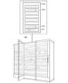
ここで図1Bを参照すると、コントローラファーム160は、コントローラ150a~n及び制御マネージャ152を含むいくつかのブレード150a~n、152を各々有する1つまたはいくつかのブレードサーバを含み得る。ブレード150a~n、152の各々は、分散型コントローラ11と同様の1つ以上のプロセッサ及びメモリを有する薄い電子回路基板であり得る。ブレード150a~n、152の各々内のプロセッサは、マルチコアプロセッサまたは別の種類のパラレルプロセッサのようなマルチコアハードウェアを含み得る。加えて、ブレード150a~n、152の各々内のメモリは、高密度メモリス
トレージ技術、例えば、ソリッドステートドライブメモリ、半導体メモリ、光メモリ、分子メモリ、生体メモリ、または任意の他の好適な高密度メモリ技術を含み得る。いくつかの実施形態では、メモリストレージはフラッシュメモリも含み得る。メモリステージ(及び、いくつかの場合では、フラッシュメモリ)は、それぞれのブレード150a~n、152に生成され、受信され、または他の方法で観測されるデータを一時的に記憶またはキャッシュするように構成され得る。Referring now to FIG. 1B, a
本明細書で「コントローラ」(例えば、コントローラ1、コントローラ2、…コントローラN)としても称されるブレード150a~nは、プロセスプラント10のフィールドデバイス15~22、40~46及び/またはプロセス制御システム100内の他のプロセスプラントのフィールドデバイスの各々に通信可能に接続される。いくつかの実施形態では、ブレード150a~nは、フィールドデバイス15~22、40~46の各々にエレクトロニックマーシャリングコンポーネント(例えば、Emerson Process Managementによって提供されるCHARacterization ModuleまたはCHARM)を介して通信可能に接続される。エレクトロニックマーシャリングコンポーネントは、1つ以上のCHARM I/Oカード及び単独で構成可能なチャネル(CHARM)をサポートするCHARMキャリアのようなエレクトロニックマーシャリングブロックまたは装置に含まれ得る。いくつかの実施形態では、ブレード150a~nは、ネットワークバックボーン105、無線ゲートウェイ35、または任意の他の好適な通信ネットワークを介してCHARM I/Oカードと無線通信する。その後、CHARM I/Oカードは、フィールドデバイス15~22、40~46に通信可能に(例えば、有線または無線の方法で)接続されるCHARMと通信する。
いずれのイベントにおいても、各コントローラ150a~nは、プロセスの少なくとも一部分を制御するために、フィールドデバイス15~22、40~46のサブセットに対応する制御ルーチンまたはモジュールを含む。コントローラファーム160内のいくつかのコントローラ150a~nが制御信号をフィールドデバイスの15~22、40~46の同じサブセットに提供し得る一方で、複数のコントローラ150a~nは、制御信号を同じフィールドデバイスに及び/または同じ時間間隔内で同じパラメータのために提供しないことがある。例えば、第1のコントローラ150a及び第2のコントローラ150bは、同じ時間間隔内でバルブに開放または閉鎖するように命令する同じバルブに制御信号を提供しないことがある。いくつかの実施形態では、複数のコントローラ150a~nが制御信号を同じフィールドデバイスに及び/または同じ時間間隔内で同じパラメータのために提供できないように、制御マネージャ152は制御モジュールをコントローラ150a~nに割り当てる。これに加えて、またはこれに代えて、コントローラファーム160内の制御監視モジュールは、任意の2つの制御出力が同じフィールドデバイスに向かうか及び/または同じ時間間隔内で同じパラメータのためであるかを判定するために、コントローラ150a~nからの制御出力を監視し得る。これが発生する場合、制御監視モジュールは、制御信号のうちのただ1つがフィールドデバイスに提供されることを確実にするために、制御信号をオーバーライドし得る。制御監視モジュールは、その時間間隔の間、フィールドデバイスに制御信号を提供することを停止するために、コントローラ150a~nのうちの1つまたは制御マネージャ152にリクエストも提供し得る。しかしながら、複数のコントローラ150a~nは、同じバルブからのバルブ開放パーセントのような、同じ時間間隔内の同じフィールドデバイスからの出力を受信し得る。 In any event, each
いくつかの実施形態では、コントローラ150a~nによって実行される制御ルーチンまたはモジュールの各々のために、コントローラ150a~nのうちの1つは冗長モジュールを含み得る。冗長モジュールは、制御モジュールを現在実行しているコントローラ150aが失敗した場合に、冗長モジュールを実行するコントローラ150bが制御モジュールを引き継いで実行できるように、冗長モジュールを実行するコントローラ150bを
、制御モジュールを実行するコントローラ150aと同期させ得る。制御モジュールを実行するコントローラ150aと同期するために、冗長モジュールは、冗長モジュールを実行するコントローラ150bに、制御モジュールを実行するコントローラ150aによって受信及び提供される同じ入力、出力、設定点等を受信させ得る。制御モジュールを実行するコントローラ150aは、冗長モジュールを実行するコントローラまたはブレード150bと異なるコントローラまたはブレードであり得る。制御モジュールと同様に、冗長モジュールはソフトウェア、ファームウェア、ハードウェア等であり得る。冗長モジュールは、任意の所望のソフトウェアフォーマットで、例えばオブジェクト指向プログラミング、ラダーロジック、シーケンシャル機能チャート、機能ブロックダイアグラムを使用して、または任意の他のソフトウェアプログラミング言語または設計パラダイムを使用して実装され得る。In some embodiments, one of
また、いくつかの実施形態では、各コントローラ150a~nは、センサデータ、制御パラメータ、データに関連付けられたタイムスタンプ、またはプロセスプラントで利用可能な任意の他の種類のデータを含むプロセスプラント10からのプロセス制御データを収集し記憶するために、フィールドデバイス15~22、40~46のサブセットに対応するビッグデータモジュールを含む。これは、構成、バッチレシピ、設定点、出力、レート、制御アクション、診断、アラーム、イベント、及び/またはそれに対する変更に対応するプロセスプラント10でプロセスが制御される一方で、生成されたリアルタイムプロセスデータのような測定データ、構成データ、バッチデータ、イベントデータ、及び/または連続データを含み得る。 Also, in some embodiments, each
ビッグデータモジュールは、また、収集されたプロセス制御データを分析し得て、モジュールを開発及び/または使用し、データ傾向及び/または相関を認識し、プロセスプラント10に影響し得るか、またはすぐに影響するだろう、実際のもしくは予測された問題または異常な状況及び/または準最適な状態をプラント従業員に警告等をする。いくつかの実施形態では、ビッグデータモジュールは、特定の問題または状態を有するデータまたは傾向の特定のセットと関連するようにプログラムされることは特になくてもこれらの機能を行い、代わりに、以前の状態(肯定的/所望される状態、または否定的/所望されない状態であり得る)の時間ちょうどまたはその近辺の前に、現在の傾向またはデータの一致が発生したことを認識する。傾向またはデータの一致の以前の発生を認識することで、ビッグデータモジュールは状態を予測し得る(「予知」)。ビッグデータモジュールは、また、プロセス変数、センサ測定値等がプロセスプラント10の異常な状況の検出、予測、予防及び/または収集において最も重要である収集されたプロセス制御データから判定し得る。例えば、ビッグデータモジュールは、一連の以前のデータ点によって示される傾向が、予測される異常な状況、予測されるメンテナンスの懸念、予測される障害等を示すことを判定し得る。 The big data module may also analyze the collected process control data to develop and/or use the module to recognize data trends and/or correlations and may affect the
制御モジュールと同様に、ビッグデータモジュールはソフトウェア、ファームウェア、ハードウェア等であり得る。ビッグデータモジュールは、任意の所望のソフトウェアフォーマットで、例えばオブジェクト指向プログラミング、ラダーロジック、シーケンシャル機能チャート、機能ブロックダイアグラムを使用して、または任意の他のソフトウェアプログラミング言語または設計パラダイムを使用して実装され得る。 Like control modules, big data modules can be software, firmware, hardware, and the like. Big data modules may be implemented in any desired software format, e.g., using object-oriented programming, ladder logic, sequential function charts, functional block diagrams, or using any other software programming language or design paradigm. obtain.
コントローラ150a~nに加えて、コントローラファーム160は、制御モジュール、冗長モジュール、ビッグデータモジュール、及び任意の他の好適な動作をコントローラ150a~nに割り当てる制御マネージャ152を含む。いくつかの実施形態では、制御マネージャ152は、ハードウェアに実装され、ブレードサーバ内のブレードのうちの1つである。他の実施形態では、制御マネージャ152は、コントローラファーム160のブレード150a~n、152のいずれかで実装され得るソフトウェアアプリケーション
であり、コントローラ150aは、制御モジュール、冗長モジュール、ビッグデータモジュール等に加えて制御マネージャアプリケーションを含み得る。しかしながら、この説明全体を通して、制御マネージャ152は本明細書でブレードサーバのブレードのようなコントローラファーム160内のハードウェアデバイスとして言及され得る。コントローラファーム160は、コントローラファーム160のいくつかのブレードサーバ内のコントローラの各々の制御を管理する単一のブレード上に実装された単一の制御マネージャ152を含み得る。他の実施形態では、制御マネージャ152はいくつかのブレードにわたって実装される。さらに他の実施形態では、コントローラファーム160は、ベイ150a~n、152として称されるいくつかの搭載スロットを各々有する1つまたはいくつかのラックサーバを含む。In addition to
他の実施形態では、コントローラファーム160は、クラウドコンピューティング環境のクラウドサーバ、フォグコンピューティング環境のフォグサーバを含み、フォグコンピューティング環境は、例えば、プロセス制御システム100内のプロセスプラント(複数可)10、またはそれらの任意の好適な組み合わせを運転する組織によってホストされる。例えば、クラウドコンピューティング環境はアメリカ合衆国全体またはさらに世界全体を通してプロセスプラント10でプロセスを制御するコントローラを含み得る一方で、フォグコンピューティング環境は特定の市または街のプロセスプラント10または特定の組織によって所有及び運転されるプロセスプラント10でプロセスを制御するコントローラを含み得る。 In other embodiments, the
いずれのイベントにおいても、制御マネージャ152は制御モジュール、冗長モジュール、ビッグデータモジュール等を1つまたはいくつかのUIデバイス112で生成される構成アプリケーションから取得し得る。いくつかの実施形態では、制御マネージャ152は、対応する制御モジュールの取得に際して冗長モジュールを自動的に生成する。ここで図2を参照すると、制御マネージャ152はコントローラファーム160のいくつかのコントローラ150a~nと通信する。コントローラ150a~nの各々及び制御マネージャ152は、物理的機械(例えば、ハードウェア)または仮想機械(例えば、ソフトウェア)であり得る。この方法では、コントローラファーム160のブレードは、いくつかのゲスト仮想機械またはコントローラをホストし得る。いずれのイベントにおいても、制御マネージャ152は、制御エグゼクティブ200、ロードバランサ202、シャドウデータベース204、冗長マネージャ206、制御モジュール208、及びビッグデータモジュール(図示されない)を含む。コントローラ1~N(参照番号150a~n)の各々は、マルチコアプロセッサまたは別の種類のパラレルプロセッサのようなプロセッサ210a~n及び高密度メモリであり得るメモリ212a~nを含む。メモリ212a~nの各々は、制御モジュール214a~n、ビッグデータモジュール216a~n、及び冗長モジュール218a~nを含むそれぞれのコントローラ150a~nに割り当てられる様々なルーチンを記憶し得る。 In any event,
プロセスプラント10内で動作を制御及び監視するためにルーチンを記憶及び実行することに加えて、コントローラ150a~nは、制御マネージャ152に可用性の指標を提供し得る。いくつかの実施形態では、コントローラ150a~nの各々は、コントローラ150a~nでのロード、コントローラ150a~nでのメモリの利用可能な量、及び特定の時間間隔でのコントローラ150a~nからのデータ伝達の帯域幅に基づいて、特定の時間間隔の可用性メトリックを制御マネージャ152に提供する。他の実施形態では、コントローラ150a~nの各々は、コントローラ150a~nでのロード、コントローラ150a~nでのメモリの利用可能な量、及び特定の時間間隔のコントローラ150a~nからのデータ伝達の帯域幅の指標を提供する。その後、制御マネージャ152は、各コントローラ150a~nの特定の時間間隔の可用性メトリックをこの情報に基づいて判定する。コントローラ150a~nでのロードは、コントローラ150a~n(例えば、
シングルコア、デュアルコア、クアッドコア等)の処理能力と並んでコントローラ150a~nによって行われる処理量を示し得る。In addition to storing and executing routines to control and monitor operations within
It may indicate the amount of processing performed by the
制御マネージャ152の制御エグゼクティブ200は、制御モジュール208、冗長モジュール、ビッグデータモジュール等のような、コントローラファーム160のコントローラ150a~nによって行われるべき動作を、1つまたはいくつかのUIデバイス112で、またはプロセス制御システム100内の他のアプリケーションもしくはデバイスから生成された構成アプリケーションから受信し得る。いくつかの実施形態では、冗長マネージャ206は、制御マネージャ152から取得される各制御モジュール208のために冗長モジュールを生成する。冗長モジュールは、冗長モジュールを実行するコントローラ150a~nに、制御モジュールに含まれる制御ループまたは関数を実行することなく制御モジュールを実行するコントローラ150a~nによって受信及び提供される同じ入力、出力、設定点等を受信させ得る。いくつかの実施形態では、制御エグゼクティブ200は、冗長マネージャが対応する冗長モジュールを生成するために、取得された制御モジュール208の各々を冗長マネージャ206に提供する。 The
また、いくつかの実施形態では、制御エグゼクティブ200は、制御モジュール208、冗長モジュール、及びビッグデータモジュールの各々に優先レベルを割り当て、優先の順番でモジュールを順位付ける。優先レベルは、優先規則の既定のセットに基づいて自動的に割り当てられ得る(例えば、冗長モジュールは対応する制御モジュールと同じ優先レベルを有し、制御モジュールはビッグデータモジュールより高い優先レベルを有する等)。これに加えて、またはこれに代えて、ユーザはモジュールの各々に優先レベルを割り当て得る。例えば、構成エンジニアが構成アプリケーションを介して制御モジュールを生成する場合、構成エンジニアも制御モジュールに優先レベルを割り当て得る。 Also, in some embodiments,
制御エグゼクティブ200は、どのコントローラ150a~nがどの制御モジュール208、冗長モジュール、及びビッグデータモジュールを特定の時間間隔の間に実行するべきかを判定するためにロードバランサ202と通信し得る。いくつかの実施形態では、ロードバランサ202は、コントローラファーム160のコントローラ150a~nの各々の可用性メトリック、ならびにモジュールの各々のそれぞれの優先レベルを含み得る、特定の時間間隔(例えば、30分、1時間、2日、1日等)内で実行されるべき制御モジュール、冗長モジュール、及びビッグデータモジュールのリストを受信する。その後、ロードバランサ202は、モジュールの各々を実行するために、コントローラファーム160のコントローラ150a~nを割り当てる。いくつかのシナリオにおいては、コントローラ150a~nのパラレル処理能力及びメモリ密度によって、単一のコントローラ150a~nは、同じ時間間隔内でいくつかのモジュールを実行し得る。別の例示的なシナリオにおいては、冗長モジュールを実行するコントローラ150a~nがコントローラでの障害の場合には制御モジュールを実行するコントローラ150a~nを引き継ぐことができるように、ロードバランサ202は2つの異なるコントローラ150a~nを識別して制御モジュール及び冗長モジュールを実行する。 The
いくつかの実施形態では、ロードバランサ202は、各モジュールが周期的に実行されるか、またはイベントの発生に基づく(イベント駆動型)かのどちらであるか、各モジュールの実行時間、もしくは任意の他の好適な特性のようなモジュールの各々の特性を識別する。その後、ロードバランサ202は、コントローラ150a~nを識別し、コントローラ150a~nの可用性メトリックならびにモジュールの優先レベル及び特性に基づいてモジュールを実行する。より具体的には、ロードバランサ202は、ロードバランシングアルゴリズムを使用し、モジュールを実行するコントローラ150a~nを割り当てる。 In some embodiments, the
例えば、ロードバランサ202は、それらのそれぞれの可用性メトリックに従ってコントローラ150a~nの各々を順位付け得て、最高の可用性メトリックを有するコントローラ150a~nは、可用性の最大の量を有し、最高として順位付けられる。ロードバランサ202も、優先レベル及び各モジュールの特性の組み合わせに基づいてモジュールの各々を順位付け得る。いくつかの実施形態では、周期モジュールはイベント駆動型モジュールより上に順位付けられ、その後、優先レベルに基づいて周期モジュールの各々は分類され、優先レベルに基づいてイベント駆動型モジュールの各々は分類される。高優先カテゴリの周期モジュールの各々は、中優先カテゴリの周期モジュールの各々より上に順位付けられ得る等である。同じ優先カテゴリの周期またはイベント駆動型モジュールは、さらに実行時間に基づいて順位付けられ得る。さらに具体的には、3つの優先カテゴリ(高、中、及び低)ならびに周期及びイベント駆動型モジュールがある場合、高優先周期モジュールがまず順位付けられ得て、実行時間によってこのカテゴリの各モジュールはさらに順位付けられ、その後、中優先周期モジュール、その後、低優先周期モジュール、その後、高優先イベント駆動型モジュール等が続く。 For example, the
したがって、ロードバランサ202はコントローラ150a~nを順位付け得て、モジュールを順位付け得る。コントローラ150a~nは可用性メトリックによって上の例で順位付けられ、モジュールは優先レベル及びモジュール特性によって順位付けられる一方で、コントローラ150a~n及びモジュールは任意の好適な方法で順位付けられ得る。 Accordingly, the
その後、ロードバランサ202は、逆ラウンドロビンメカニズムを使用し得て、最高順位のモジュール(例えば、最長の実行時間を有する高優先周期モジュール)を最高順位のコントローラ150a~n(例えば、最高の可用性メトリックを有するコントローラ)にまず割り当てる。2番目に高い順位のモジュールは、2番目に高い順位のコントローラ150a~nに割り当てられ得て、アルゴリズムはこの方法で、最低順位のコントローラ150a~nがモジュールを割り当てられるまで、継続し得る。割り当てるモジュールがより多くある場合、ロードバランサ202はモジュールを逆の順番で割り当てるために継続する。例えば、ロードバランサ202は、また、次のモジュールを最低順位のコントローラ150a~nに割り当て、その後、次のモジュールより下に順位付けられたモジュールを2番目に低い順位のコントローラ150a~nに割り当て、最高順位のコントローラ150a~nが2つのモジュールを割り当てられるまで増加する順番で継続する。その後、ロードバランサ202が順番をもう一度逆にし、低減する順番でモジュールを割り当て、モジュールの各々がコントローラ150a~nに割り当てられるまで逆ラウンドロビン方法で継続する。 The
ロードバランサ202がコントローラ150a~n及びモジュールを順位付け、逆ラウンドロビンメカニズムを使用してコントローラ150a~nにモジュールを割り当て得る一方で、ロードバランサ202は、任意の好適な方法でモジュールをコントローラ150a~nに割り当て得て、コントローラファーム160のコントローラ150a~nの間でモジュールを分散する。他の実施形態では、モジュールは、優先レベルまたは特性に関わらずコントローラ150a~nの間で等しくまたは少なくとも同様に分散される。さらに他の実施形態では、ロードバランサ202は、コントローラ150aで処理が容量に達するまで、モジュールを同じコントローラ150aに割り当てる。その後、ロードバランサ202は、別のコントローラ150bで処理が容量に達するまで、モジュールを別のコントローラ150bに割り当て、ロードバランサ202はこの方法でモジュールを割り当て続け得る。 While
いずれのイベントにおいても、制御エグゼクティブ200は、各コントローラ150a~nが割り当てられたモジュールを実行し得るように、その後、対応するコントローラ150a~nに割り当てられたモジュールを提供する。いくつかの実施形態では、制御エグ
ゼクティブ200は割り当てを分析し、複数のコントローラ150a~nが制御信号を同じフィールドデバイスに及び/または同じ時間間隔内で同じパラメータのために提供しないことを確実にするために、割り当てのうちのいくつかを調整し得る。In any event,
例示的なシナリオにおいては、第1の時間間隔の間、コントローラ150aは、制御モジュール、ビッグデータモジュール、及び冗長モジュールを含むモジュールの第1のセットを割り当てられ得る。制御エグゼクティブ200は、第1の時間間隔の間、制御モジュール214a、ビッグデータモジュール216a、及び冗長モジュール218aをコントローラ150aにダウンロードし得る。その後、第2の時間間隔の間、コントローラ150aは、モジュールの第1のセットから異なるモジュールの第2のセットを割り当てられ得る。制御エグゼクティブ200は、第2の時間間隔の間、制御モジュール214a、ビッグデータモジュール216a、及び冗長モジュール218aをコントローラ150aにダウンロードし得る。 In an exemplary scenario, during a first time interval,
別の例示的なシナリオにおいては、特定の時間間隔の間、制御マネージャ152は第1の制御モジュールを第1のコントローラ150aに割り当て、第1の制御モジュールはフィールドデバイス15~22、40~46の第1のサブセットに対応する。制御マネージャ152は第2の制御モジュールを第2のコントローラ150bに割り当て、第2の制御モジュールはフィールドデバイス15~22、40~46の第2のサブセットに対応する。フィールドデバイス15~22、40~46の第1及び第2のサブセットは、同じプロセスプラント10または異なるプロセスプラント10の異なるエリアに配置され得る。第1のコントローラ150aが、その後、第1の制御モジュールを実行し、第2のコントローラ150bが、同じ時間間隔内で、第2の制御モジュールを実行する。より遅い時間間隔の間、第1のコントローラ150aが第1の制御モジュールをもはや割り当てられず、第2のコントローラ150bが第1及び第2の制御モジュールの両方を割り当てられる。例えば、第1のコントローラ150aは、より遅い時間間隔の間、第1の制御モジュールを実行する処理リソースを有し得ない。その後、第2のコントローラ150bは、より遅い時間間隔の間、それぞれフィールドデバイス15~22、40~46の第1及び第2のサブセットのための第1及び第2の制御モジュールを実行する。 In another exemplary scenario, the
いくつかの実施形態では、いくつかの時間間隔の間、周期モジュールは同じコントローラ150a~nに割り当てられたままであり、一方で、イベント駆動型モジュールは、特定の時間間隔でのコントローラ150a~nの可用性メトリックに基づいて、各時間間隔の間、コントローラ150a~nに再割り当てされる。他の実施形態では、制御モジュール208、ビッグデータモジュール、及び冗長モジュールの各々は、実行の前(例えば、モジュールが生成されるとき)に、コントローラ150a~nの各々にダウンロードされ、それらのそれぞれのメモリ212a~nで記憶される。制御エグゼクティブ200は、特定のモジュールを実行するためにコントローラ150aを選択するとき、制御マネージャ152は、特定のモジュールの指標を選択されたコントローラ150aに提供し、選択されたコントローラ150aは特定のモジュールをメモリ212aから読み出し、特定のモジュールを実行する。 In some embodiments, the periodic modules remain assigned to the
いくつかの実施形態では、制御マネージャ152は、制御モジュール208、冗長モジュール、及びビッグデータモジュールのために入力データを記憶するシャドウデータベース204を含む。モジュールが例えば構成アプリケーションを介して生成される場合、モジュールのための入力データはUIデバイス112から取得され得る。コントローラ150a~nが制御モジュール214a~n及びビッグデータモジュール216a~nを実行する場合、入力データは、また、コントローラ150a~nから取得され得る。制御モジュール214a~n及びビッグデータモジュール216a~nからの出力は、シャドウデータベース204でコントローラ150a~nから受信され得て、後続の時間間隔の間に
実行される制御モジュール208、冗長モジュール、及びビッグデータモジュールのための入力データとして記憶される。In some embodiments,
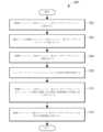
図3は、プロセス制御システム100のコントローラの間でのロードバランシングのための例示的な方法300を表すフロー図を示す。方法300は、コントローラファーム160内の制御マネージャ152上またはコントローラファーム160内またはコントローラファーム160と通信している任意の他のコンピューティングデバイス、ブレードサーバ等の上で実行され得る。一部の実施形態において、方法は、非一時的コンピュータ可読メモリ上に記憶されている命令のセットに実装され得て、制御マネージャ152の1つ以上のプロセッサによって実行可能である。 FIG. 3 shows a flow diagram representing an
ブロック302で、制御モジュール、冗長モジュール、及びビッグデータモジュールは取得される。例えば、モジュールは構成アプリケーションを介してUIデバイス112から取得され得る。いくつかの実施形態では、制御モジュールが取得され、冗長モジュールを実行するコントローラが、制御モジュールを実行するコントローラによって受信及び提供される同じ入力、出力、設定点等を受信するように、冗長モジュールは、各制御モジュールのために自動的に生成される。 At
その後、優先レベルが、制御モジュール、冗長モジュール、及びビッグデータモジュールの各々(ブロック304)に割り当てられる。優先レベルは、数値の優先レベル(例えば、1、2、3)であり得、カテゴリのセットからのカテゴリ(例えば、高、中、低)であり得、または任意の好適な優先の指標であり得る。いくつかの実施形態では、優先レベルは、例えばユーザによって割り当てられ、その際にモジュールは構成アプリケーションを介して作成される。他の実施形態では、優先レベルは、優先規則の既定のセットに基づいて自動的に割り当てられる(例えば、冗長モジュールは対応する制御モジュールと同じ優先レベルを有し、制御モジュールはビッグデータモジュールより高い優先レベルを有する等)。 A priority level is then assigned to each of the control, redundancy and big data modules (block 304). The priority level can be a numerical priority level (eg, 1, 2, 3), can be a category from a set of categories (eg, high, medium, low), or can be any suitable indicator of priority. obtain. In some embodiments, priority levels are assigned by, for example, a user when modules are created via a configuration application. In other embodiments, priority levels are automatically assigned based on a predefined set of priority rules (e.g., redundant modules have the same priority level as their corresponding control modules, and control modules are higher than big data modules). have priority levels, etc.).
その後、ブロック306で、制御モジュール、冗長モジュール、及びビッグデータモジュールの各々は順位付けられる。いくつかの実施形態では、モジュールは優先レベルの順番で順位付けられる。モジュールは、各モジュールが周期的に実行されるか、またはイベントの発生に基づく(イベント駆動型)かのどちらであるか、各モジュールの実行時間、もしくは任意の他の好適な特性のようなモジュールの特性に従ってさらに順位付けられ得る。例えば、周期モジュールは、イベント駆動型モジュールより上に順位付けられ得て、周期モジュールは優先レベルに従ってさらに順位付けられ得る。イベント駆動型モジュールも、優先レベルに従ってさらに順位付けられ得る。その後、最高の優先レベルを有する周期モジュールの各々が、実行時間に従って順位付けられ得て、最高の優先レベル及び最長の実行時間を有する周期モジュールは最高に順位付けられる。他の実施形態では、モジュールは、優先レベル及びモジュール特性の任意の好適な組み合わせを使用して、または任意の好適な方法で順位付けられ得る。 Thereafter, at
可用性の指標は、特定の時間間隔(ブロック308)の間のコントローラファーム160のコントローラ150a~nの各々のために取得される。例えば、各コントローラ150a~nは、コントローラ150a~nでのロード、コントローラ150a~nでのメモリの利用可能な量、及び特定の時間間隔でのコントローラ150a~nからのデータ伝達の帯域幅に基づいて、特定の時間間隔の可用性メトリックを生成し得る。その後、コントローラ150a~nは、それぞれの可用性メトリックを制御マネージャ152に提供し得る。別の実施例では、各コントローラ150a~nは、コントローラ150a~nでのロードの指標、コントローラ150a~nでのメモリの利用可能な量、及び特定の時間間隔のコントローラ150a~nからのデータ伝達の帯域幅を提供し得る。その後、制御マネ
ージャ152は、各コントローラ150a~nの特定の時間間隔の可用性メトリックをこの情報に基づいて判定する。An availability indicator is obtained for each of the
いくつかの実施形態では、制御マネージャ152は、特定の時間間隔の可用性メトリックをこの情報に基づいて、コントローラ150a~nの各々を順位付ける。例えば、最高の可用性メトリックを有し、それゆえ可用性の最大の量を有するコントローラ150a~nは、最高として順位付けられる。その後、コントローラ150a~nは、可用性の降順で順位付けられる。 In some embodiments,
ブロック310で、制御モジュール、冗長モジュール、及びビッグデータモジュールはコントローラ150a~nに割り当てられる。コントローラファーム160内のコントローラ150a~nの間のロードをバランシングするために、制御マネージャ152は、コントローラ150a~nの各々にわたって制御モジュール、冗長モジュール、及びビッグデータモジュールを分散し得る。いくつかの実施形態では、制御マネージャ152は、ロードバランシングアルゴリズムを使用し、コントローラ150a~nにモジュールを割り当てる。例えば、ロードバランシングアルゴリズムは逆ラウンドロビンメカニズムであり得て、制御マネージャ152は最高順位のモジュールを最高順位のコントローラ150a~nに割り当て、その後、2番目に高い順位のモジュールを2番目に高い順位のコントローラ150a~nに割り当て、各コントローラ150a~nがモジュールを割り当てられるまで降順で継続する。その後、制御マネージャ152は、各コントローラ150a~nが2つのモジュールを割り当てられるまで、残っている制御モジュールをコントローラ150a~nに昇順で割り当てる。制御マネージャ152は、モジュールの各々が割り当てられるまで、コントローラ150a~nがモジュールを割り当てられる順番を交代する。 At
別の実施例では、制御マネージャ152は最高順位のモジュールを最高順位のコントローラ150a~nに割り当て、その後、2番目に高い順位のモジュールを2番目に高い順位のコントローラ150a~nに割り当て、各コントローラ150a~nがモジュールを割り当てられるまで降順で継続する。その後、制御マネージャ152は次の順位のモジュールを最高順位のコントローラ150a~nに割り当て、もう一度コントローラ150a~nの降順で継続し、モジュールの各々が割り当てられるまでこのプロセスを繰り返す。 In another embodiment,
さらに別の実施例では、制御マネージャ152は、コントローラ150a~nがモジュールを割り当てられる順番をランダムに選択し、その後、ランダムに選択された順番に従ってモジュールをコントローラ150a~nに割り当てる。別の実施例では、制御マネージャ152は、最高順位のコントローラ150a~nが全容量に到達するまで、モジュールを最高順位のコントローラ150a~nに降順で割り当てる。その後、制御マネージャ152は、2番目に高い順位のコントローラ150a~nが全容量に到達するまで、次の順位のモジュールを2番目に高い順位のコントローラ150a~nに降順で割り当て、モジュールの各々が割り当てられるまでこの方法で繰り返す。これらは、モジュールがコントローラ150a~nに割り当てられ得るほんの数例であるが、モジュールは任意の好適な方法で割り当てられてもよい。 In yet another embodiment,
ブロック312では、割り当てられたモジュールは、特定の時間間隔の間、実行のためにそれぞれのコントローラ150a~nにダウンロードされる。各コントローラ150a~nは、制御信号を提供することによって、そうでなければ各割り当てられたモジュールに関連付けられたフィールドデバイス15~22、40~46と通信することによって、その割り当てられたモジュールを実行する At
本開示に記載されている技術の実施形態は、任意の数の下記の態様を、単独でまたは組み合わせて含んでよい。 Implementations of the technology described in this disclosure may include any number of the following aspects, singly or in combination.
1.プロセス制御システムであって、プロセス制御システムでプロセスの少なくとも一部分を制御するために物理的機能を各々実行するように構成された複数のフィールドデバイスと、複数のフィールドデバイスの各々に通信可能に連結されたコントローラファームの複数のコントローラと、を備え、複数のコントローラの各々が、物理的機能に対応する複数のフィールドデバイスに制御信号を伝達することによってプロセスを制御するために、複数のフィールドデバイスに対応する同じ制御モジュールを実行するように構成されており、複数のコントローラのうちの1つが制御モジュールを特定の時間間隔で実行するために選択される、プロセス制御システム。 1. A process control system, a plurality of field devices each configured to perform a physical function to control at least a portion of a process in the process control system; and communicatively coupled to each of the plurality of field devices. and a plurality of controllers in a controller farm, each of the plurality of controllers serving the plurality of field devices to control the process by communicating control signals to the plurality of field devices corresponding to the physical function. and wherein one of a plurality of controllers is selected to execute the control module at specific time intervals.
2.コントローラファームが、温度制御エリアに配置されている、態様1に従ったプロセス制御システム。 2. The process control system according to
3.複数のフィールドデバイスが、第1の複数のフィールドデバイスであり、第2の複数のフィールドデバイスをさらに備え、複数のコントローラの各々は、第1の複数のフィールドデバイスに対応する第1の制御モジュール及び第2の複数のフィールドデバイスに対応する第2の制御モジュールを実行するために構成され、第1のコントローラは第1の制御モジュールを実行するために選択され、第2のコントローラは第2の制御モジュールを特定の時間間隔で実行するために選択される、態様1または2のいずれか1つに記載のプロセス制御システム。 3. the plurality of field devices being a first plurality of field devices and further comprising a second plurality of field devices, each of the plurality of controllers being a first control module corresponding to the first plurality of field devices; configured to execute a second control module corresponding to a second plurality of field devices, the first controller selected to execute the first control module and the second controller the second control module; 3. The process control system of any one of
4.第1の複数のフィールドデバイス及び第2の複数のフィールドデバイスが同じプロセスプラント内に配置されている、態様1~3のいずれか1つに記載のプロセス制御システム。 4. 4. The process control system of any one of aspects 1-3, wherein the first plurality of field devices and the second plurality of field devices are located within the same process plant.
5.第1の複数のフィールドデバイス及び第2の複数のフィールドデバイスが異なるプロセスプラント内に配置されている、態様1~4のいずれか1つに記載のプロセス制御システム。 5. 5. The process control system of any one of aspects 1-4, wherein the first plurality of field devices and the second plurality of field devices are located in different process plants.
6.別の時間間隔で、第1のコントローラが第1の制御モジュールを実行せず、第2のコントローラが第1の制御モジュール及び第2の制御モジュールを実行する、態様1~5のいずれか1つに記載のプロセス制御システム。 6. 6. Any one of aspects 1-5, wherein the first controller does not execute the first control module and the second controller executes the first control module and the second control module at another time interval The process control system according to .
7.第2のコントローラが第1の制御モジュールに対応する冗長モジュールを実行する、態様1~6のいずれか1つに記載のプロセス制御システム。 7. 7. The process control system of any one of aspects 1-6, wherein the second controller executes a redundant module corresponding to the first control module.
8.コントローラファームの複数のコントローラの各々が、それぞれのフィールドデバイスに通信可能に連結された入力/出力(I/O)デバイスを介して各複数のフィールドデバイスと通信する、態様1~7のいずれか1つに記載のプロセス制御システム。 8. 8. Any one of aspects 1-7, wherein each of the plurality of controllers of the controller farm communicates with each plurality of field devices via an input/output (I/O) device communicatively coupled to the respective field device The process control system according to 1.
9.選択されたコントローラが、プロセスに対応する構成データ、連続データ、及びイベントデータのうち少なくとも1つを含むプロセスに対応するデータを取得及び記憶するようにさらに構成されている、態様1~8のいずれか1つに記載のプロセス制御システム。 9. 9. Any of aspects 1-8, wherein the selected controller is further configured to retrieve and store data corresponding to the process including at least one of configuration data, continuous data, and event data corresponding to the process. A process control system according to
10.特定の時間間隔で実行するために複数のコントローラの各々に制御モジュールを割り当てるように構成された、複数のコントローラに通信可能に連結されたコンピューティングデバイスをさらに備える、態様1~9のいずれか1つに記載のプロセス制御システム。 10. 10. Any one of aspects 1-9, further comprising a computing device communicatively coupled to the plurality of controllers configured to assign a control module to each of the plurality of controllers for execution at specified time intervals. The process control system according to 1.
11.コンピューティングデバイスが複数のコントローラの各々からロード、帯域幅、及び利用可能なメモリの指標を取得し、各コントローラのロード、帯域幅、または利用可能なメモリのうちの少なくとも1つに従って複数のコントローラに制御モジュール、冗長モジュール、及びビッグデータモジュールを割り当てる、態様1~10のいずれか1つに記載のプロセス制御システム。 11. A computing device obtains load, bandwidth, and available memory indicators from each of a plurality of controllers and outputs the load, bandwidth, and available memory indicators to the plurality of controllers according to at least one of each controller's load, bandwidth, or available memory. 11. The process control system of any one of aspects 1-10, allocating control modules, redundancy modules, and big data modules.
12.コンピューティングデバイスがコントローラファーム内の複数のコントローラのうちの1つである、態様1~11のいずれか1つに記載のプロセス制御システム。 12. 12. The process control system of any one of aspects 1-11, wherein the computing device is one of a plurality of controllers in a controller farm.
13.コンピューティングデバイスが、複数のコントローラによって実行される複数の制御モジュールを取得し、割り当てられた優先レベルに従って複数の制御モジュールを順位付けする、態様1~12のいずれか1つに記載のプロセス制御システム。 13. 13. The process control system of any one of aspects 1-12, wherein the computing device obtains a plurality of control modules executed by a plurality of controllers and ranks the plurality of control modules according to assigned priority levels. .
14.コンピューティングデバイスが、複数の制御モジュールの各々のそれぞれの順位の順番で、複数のコントローラに制御モジュールを割り当て、最高順位の制御モジュールが最初に割り当てられる、態様1~13のいずれか1つに記載のプロセス制御システム。 14. 14. The computing device of any one of aspects 1-13, wherein the computing device assigns control modules to the plurality of controllers in order of respective ranking of each of the plurality of control modules, the highest ranking control module being assigned first. of process control systems.
15.コントローラファームを介してプロセス制御システム内の1つ以上のプロセスプラントで複数のフィールドデバイスを制御する方法であって、コントローラファームの複数のコントローラによって、プロセス制御システムでプロセスの少なくとも一部分を制御するために、物理的機能を実行するように各々構成された複数のフィールドデバイスに制御信号を伝達することであって、複数のコントローラの各々が、プロセスを制御するために、複数のフィールドデバイスに対応する同じ制御モジュールを実行するように構成されている、伝達することと、制御モジュールを特定の時間間隔で実行するために複数のコントローラのうちの1つを選択することと、選択されたコントローラによって、特定の時間間隔の間、制御モジュールに従って複数のフィールドデバイスに制御信号を選択されたコントローラによって伝達することと、を含む、方法。 15. A method of controlling a plurality of field devices at one or more process plants in a process control system via a controller farm for controlling at least a portion of a process in the process control system by a plurality of controllers of the controller farm. , communicating control signals to a plurality of field devices each configured to perform a physical function, wherein each of the plurality of controllers controls the same controller corresponding to the plurality of field devices to control the process. communicating, configured to execute a control module; selecting one of a plurality of controllers to execute the control module at a particular time interval; communicating, by a selected controller, control signals to the plurality of field devices according to the control module during the time intervals of .
16.コントローラファームが、温度制御エリアに配置されている、態様15に記載の方法。 16. 16. The method of aspect 15, wherein the controller farm is located in a temperature controlled area.
17.複数のフィールドデバイスが、第1の複数のフィールドデバイスであり、複数のコントローラの各々は、第1の複数のフィールドデバイスに対応する第1の制御モジュール及び第2の複数のフィールドデバイスに対応する第2の制御モジュールを実行するために構成され、第1の制御モジュールを特定の時間間隔で実行するために第1のコントローラを選択することと、第1のコントローラによって、特定の時間間隔の間、第1の制御モジュールに従って第1の複数のフィールドデバイスに制御信号を伝達することと、第2の制御モジュールを特定の時間間隔で実行するために第2のコントローラを選択することと、第2のコントローラによって、特定の時間間隔の間、第2の制御モジュールに従って第2の複数のフィールドデバイスに制御信号を伝達することと、をさらに含む、態様15または態様16のいずれか1つに記載の方法。 17. The plurality of field devices is a first plurality of field devices, and each of the plurality of controllers is a first control module corresponding to the first plurality of field devices and a second plurality corresponding to the second plurality of field devices. selecting a first controller configured to execute two control modules and executing the first control module for a specific time interval; by the first controller for the specific time interval; communicating control signals to a first plurality of field devices according to a first control module; selecting a second controller to execute the second control module for a particular time interval; 17. The method of any one of aspects 15 or 16, further comprising communicating, by the controller, control signals to the second plurality of field devices according to the second control module for the specified time interval. .
18.第1の複数のフィールドデバイス及び第2の複数のフィールドデバイスが同じプロセスプラント内に配置されている、態様15~17のいずれか1つに記載の方法。 18. 18. The method of any one of aspects 15-17, wherein the first plurality of field devices and the second plurality of field devices are located within the same process plant.
19.第1の複数のフィールドデバイス及び第2の複数のフィールドデバイスが異なるプロセスプラント内に配置されている、態様15~18のいずれか1つに記載の方法。 19. 19. The method of any one of aspects 15-18, wherein the first plurality of field devices and the second plurality of field devices are located in different process plants.
20.別の時間間隔で、第1のコントローラが第1の制御モジュールを実行せず、第2のコントローラによって、別の時間間隔の間、第1の制御モジュールに従って第1の複数
のフィールドデバイスに制御信号を伝達することをさらに含む、態様15~19のいずれかに記載の方法。20. At another time interval, the first controller does not execute the first control module, and the second controller controls signals to the first plurality of field devices according to the first control module for the another time interval. 20. The method of any of aspects 15-19, further comprising communicating the
21.第2のコントローラによって、第1の制御モジュールに対応する冗長モジュールを実行することをさらに含む、態様15~20のいずれかに記載の方法。 21. 21. The method of any of aspects 15-20, further comprising executing, by the second controller, a redundancy module corresponding to the first control module.
22.選択されたコントローラによって、プロセスに対応する構成データ、連続データ、及びイベントデータのうちの少なくとも1つを含むプロセスに対応するデータを取得及び記憶することをさらに含む、態様15~21のいずれかに記載の方法。 22. 22. Any of aspects 15-21, further comprising acquiring and storing, by the selected controller, data corresponding to the process including at least one of configuration data, continuous data, and event data corresponding to the process. described method.
23.複数のコントローラに通信可能に連結されたコンピューティングデバイスが特定の時間間隔で制御モジュールを実行するためにコントローラを選択する、態様15~22のいずれかに記載の方法。 23. 23. The method of any of aspects 15-22, wherein a computing device communicatively coupled to the plurality of controllers selects a controller for executing the control module at specified time intervals.
24.コンピューティングデバイスによって、複数のコントローラの各々からロード、帯域幅、及び利用可能なメモリの指標を取得することと、各コントローラのロード、帯域幅、または利用可能なメモリのうちの少なくとも1つに従って複数のコントローラに制御モジュール、冗長モジュール、及びビッグデータモジュールを割り当てることと、をさらに含む、態様15~23のいずれかに記載の方法。 24. obtaining, by a computing device, an indication of load, bandwidth, and available memory from each of a plurality of controllers; 24. The method of any of aspects 15-23, further comprising assigning control modules, redundancy modules, and big data modules to controllers of.
25.コンピューティングデバイスがコントローラファーム内の複数のコントローラのうちの1つである、態様15~24のいずれかに記載の方法。 25. 25. The method of any of aspects 15-24, wherein the computing device is one of a plurality of controllers in a controller farm.
26.プロセス制御システムにおいて制御モジュールのロードをバランシングするための方法であって、プロセス制御システム内で物理的機能を実行するように構成されたフィールドデバイスに提供される制御信号を介して、プロセス制御システムでプロセスを制御する複数の制御モジュールを取得することと、フィールドデバイスに通信可能に連結されたコントローラファームの複数のコントローラの各々から可用性メトリックを取得することと、可用性メトリックに基づいて特定の時間間隔でそれぞれの制御モジュールを実行するために複数のコントローラのうちの1つに複数の制御モジュールの各々を割り当てることと、を含む、方法。 26. A method for balancing the load of control modules in a process control system, the process control system via control signals provided to field devices configured to perform physical functions in the process control system. obtaining a plurality of control modules controlling a process; obtaining availability metrics from each of a plurality of controllers of a controller farm communicatively coupled to field devices; assigning each of the plurality of control modules to one of the plurality of controllers to execute the respective control module.
27.複数のコントローラのうちの1つに可用性メトリックを取得することは、コントローラのロード、帯域幅、及び利用可能なメモリの指標に基づいて可用性メトリックを識別することを含む、態様26に記載の方法。 27. 27. The method of aspect 26, wherein obtaining an availability metric for one of the plurality of controllers includes identifying the availability metric based on indicators of controller load, bandwidth, and available memory.
28.可用性メトリックに基づいて特定の時間間隔でそれぞれの冗長モジュールまたはビッグデータモジュールを実行するために複数のコントローラのうちの1つに1つ以上の冗長モジュール及び1つ以上のビッグデータモジュールの各々を割り当てることと、をさらに含む、態様26または態様27のいずれか1つに記載の方法。 28. assigning each of the one or more redundancy modules and one or more big data modules to one of the plurality of controllers to execute the respective redundancy module or big data module at specific time intervals based on availability metrics 28. The method of any one of aspects 26 or 27, further comprising:
29.冗長モジュール、及びビッグデータモジュールの各々に優先レベルを割り当てることと、割り当てられた優先レベルに従って制御モジュール、冗長モジュール、及びビッグデータモジュールを順位付けすることと、をさらに含む、態様26~28のいずれかに記載の方法。 29. 29. Any of aspects 26-28, further comprising assigning a priority level to each of the redundancy modules and the big data modules, and ranking the control modules, the redundancy modules and the big data modules according to the assigned priority levels. The method described in Crab.
30.制御モジュール、冗長モジュール、及びビッグデータモジュールが、それぞれの順位の順番で、複数のコントローラに割り当てられ、最高順位の制御モジュール、冗長モジュール、またはビッグデータモジュールが最初に割り当てられる、態様26~29のいずれかに記載の方法。 30. of aspects 26-29, wherein the control modules, redundancy modules, and big data modules are assigned to the plurality of controllers in their respective ranking order, with the highest ranking control module, redundancy module, or big data module being assigned first. Any method described.
31.1つ以上のプロセッサと、1つ以上のプロセッサに連結されており、内部に命令を記憶させた非一時的コンピュータ可読媒体であって、命令が、1つ以上のプロセッサによって実行されたとき、コンピューティングデバイスに、プロセス制御システム内で物理的機能を実行するように構成されたフィールドデバイスに提供される制御信号を介してプロセス制御システムでプロセスを制御する複数の制御モジュールを取得させ、複数のフィールドデバイスに通信可能に連結されたコントローラファームの複数のコントローラの各々から可用性メトリックを取得させ、可用性メトリックに基づいて特定の時間間隔でそれぞれの制御モジュールを実行するために複数のコントローラのうちの1つに複数の制御モジュールの各々を割り当てさせる、非一時的コンピュータ可読媒体と、を備える、プロセス制御システムのコンピューティングデバイス。 31. One or more processors and non-transitory computer-readable media coupled to the one or more processors and having instructions stored therein when the instructions are executed by the one or more processors , causing a computing device to obtain a plurality of control modules that control processes in the process control system via control signals provided to field devices configured to perform physical functions within the process control system; obtaining availability metrics from each of a plurality of controllers of a controller farm communicatively coupled to field devices of the plurality of controllers for executing a respective control module at a particular time interval based on the availability metric; a non-transitory computer-readable medium that causes each of the plurality of control modules to be assigned to one.
32.複数のコントローラのうちの1つに可用性メトリックを取得するために、命令がコンピューティングデバイスにコントローラのロード、帯域幅、及び利用可能なメモリの指標に基づいて可用性メトリックを識別させる、態様31に記載のコンピューティングデバイス。 32. 32. According to aspect 31, to obtain the availability metric for one of the plurality of controllers, the instructions cause the computing device to identify the availability metric based on the controller's load, bandwidth, and available memory indicators. computing device.
33.命令がさらに、コンピューティングデバイスに、可用性メトリックに基づいて特定の時間間隔でそれぞれの冗長モジュールまたはビッグデータモジュールを実行するために複数のコントローラのうちの1つに1つ以上の冗長モジュール及び1つ以上のビッグデータモジュールの各々を割り当てさせる、態様31または態様32のいずれか1つに記載のコンピューティングデバイス。 33. The instructions further instruct the computing device to perform one or more redundant modules and one or more redundant modules in one of the plurality of controllers to execute respective redundant modules or big data modules at specified time intervals based on availability metrics. 33. The computing device of any one of aspects 31 or 32, wherein each of the above big data modules is assigned.
34.命令がさらに、コンピューティングデバイスに、制御モジュール、冗長モジュール、及びビッグデータモジュールの各々に優先レベルを割り当てさせ、割り当てられた優先レベルに従って制御モジュール、冗長モジュール、及びビッグデータモジュールを順位付けする、態様31~33のいずれかに記載のコンピューティングデバイス。 34. Aspects wherein the instructions further cause the computing device to assign a priority level to each of the control module, the redundancy module, and the big data module, and rank the control module, the redundancy module, and the big data module according to the assigned priority level. 34. A computing device according to any one of 31-33.
35.制御モジュール、冗長モジュール、及びビッグデータモジュールが、それぞれの順位の順番で、複数のコントローラに割り当てられ、最高順位の制御モジュール、冗長モジュール、またはビッグデータモジュールが最初に割り当てられる、態様31~34のいずれかに記載のコンピューティングデバイス。 35. of aspects 31-34, wherein the control modules, redundancy modules, and big data modules are assigned to the plurality of controllers in their respective ranking order, with the highest ranking control module, redundancy module, or big data module being assigned first. A computing device according to any of the preceding paragraphs.
36.コンピューティングデバイスがコントローラファーム内の複数のコントローラのうちの1つである、態様31~35のいずれかに記載のコンピューティングデバイス。 36. 36. A computing device according to any of aspects 31-35, wherein the computing device is one of a plurality of controllers in a controller farm.
加えて、本開示の先の態様は、単に例示的なものであり、本開示の範囲を限定することを意図しない。 Additionally, the foregoing aspects of the disclosure are exemplary only and are not intended to limit the scope of the disclosure.
以下の追加の検討事項が、上記の考察に適用される。本明細書全体を通して、任意のデバイスまたはルーチンによって実行されるものとして記載された動作は、機械可読命令に従ってデータを操作または変換するプロセッサの動作またはプロセスを概して指す。機械可読命令は、プロセッサに通信可能に連結されたメモリデバイス上に記憶され、それから取得され得る。すなわち、本明細書に記載された方法は、コンピュータ可読媒体上に(例えば、メモリデバイス上に)記憶された機械実行可能命令のセットによって具現化され得る。命令は、対応するデバイス(例えば、オペレータワークステーション、コントローラ、制御マネージャ、UIデバイス等)の1つ以上のプロセッサによって実行されたとき、プロセッサに方法を実行させる。命令、ルーチン、モジュール、プロセッサ、サービス、プログラム、及び/またはアプリケーションが、コンピュータ可読メモリ上またはコンピュータ可読媒体上に記憶または保存されるとして本明細書において言及される場合、「記
憶(stored)」及び「保存(saved)」という語は、一時的信号を除外することが意図される。The following additional considerations apply to the discussion above. Throughout this specification, operations described as being performed by any device or routine generally refer to processor operations or processes that manipulate or transform data according to machine-readable instructions. Machine-readable instructions may be stored on and retrieved from a memory device communicatively coupled to the processor. That is, the methods described herein may be embodied by a set of machine-executable instructions stored on a computer-readable medium (eg, on a memory device). The instructions, when executed by one or more processors of corresponding devices (eg, operator workstations, controllers, control managers, UI devices, etc.), cause the processors to perform the methods. When instructions, routines, modules, processors, services, programs, and/or applications are referred to herein as being stored or saved on a computer-readable memory or on a computer-readable medium, they are "stored" and The term "saved" is intended to exclude transient signals.
さらに、「オペレータ(operator)」、「従業員(personnel)」、「人物(person)」、「ユーザ(user)」、「技術者(technician)」、「エンジニア(engineer)」という用語、及び同様の他の用語が、本明細書で記載されたシステム、装置、及び方法を使用またはそれらと相互作用し得るプロセスプラント環境内の人物を記載するために使用されるが、これらの用語は、限定を意図するものではない。特定の用語が説明で使用される場合、用語は、一部において、プラント従業員が従事する従来の活動に起因して使用されるが、特定の活動に従事し得る従業員を限定することを意図しない。 Additionally, the terms “operator,” “personnel,” “person,” “user,” “technician,” “engineer,” and the like are used to describe persons within a process plant environment who may use or interact with the systems, apparatus, and methods described herein, but these terms are not limited to is not intended to be Where specific terms are used in the description, the terms are used, in part, due to the traditional activities that plant personnel engage in, but are intended to limit the employees who may engage in specific activities. Not intended.
加えて、本明細書を通して、複数の事例は、単一の事例として記載された構成要素、動作、または構造を実装し得る。1つ以上の方法の個々の動作が別個の動作として例示及び記載されたが、個々の動作のうちの1つ以上が同時に実行されてもよく、例示された順序で動作が実行される必要はない。例示的な構成内で別個の構成要素として提示された構造及び機能は、組み合わされた構造または構成要素として実装されてもよい。同様に、単一構成要素として提示された構造及び機能は、別個の構成要素として実装されてもよい。これらの及び他の変形、修正、追加、及び改善は、本明細書の主題の範囲内にある。 Additionally, throughout this specification, multiple instances may implement a component, act, or structure that is described as a single instance. Although individual acts of one or more methods have been illustrated and described as separate acts, one or more of the individual acts may be performed simultaneously, and the acts need not be performed in the order illustrated. do not have. Structures and functions presented as separate components in exemplary configurations may be implemented as a combined structure or component. Similarly, structures and functionality presented as a single component may be implemented as separate components. These and other variations, modifications, additions and improvements are within the scope of the subject matter herein.
別途特に記載されない限り、「処理すること(processing)」、「コンピューティングすること(computing)」、「計算すること(calculating)」、「判定すること(determining)」、「識別すること(identifying)」、「提示すること(presenting)」、「提示させること(causing to be presented)」、「表示させること(causing
to be displayed)」、「表示すること(displaying)」等のような語を使用する本明細書の考察は、1つ以上のメモリ(例えば、揮発性メモリ、不揮発性メモリ、もしくはそれらの組み合わせ)、レジスタ、または情報を受信、記憶、送信、もしくは表示する他の機械構成要素内の物理(例えば、電気、磁気、生体、もしくは光)量として表されたデータを操作または変換する機械(例えば、コンピュータ)の動作またはプロセスを指し得る。Unless otherwise specified, "processing", "computing", "calculating", "determining", "identifying"","presenting","causing to be presented", "causing
Discussion herein using terms such as "to be displayed", "displaying", etc. refers to one or more memories (e.g., volatile memory, non-volatile memory, or combinations thereof). A machine that manipulates or transforms data expressed as physical (e.g., electrical, magnetic, biological, or optical) quantities in , registers, or other machine components that receive, store, transmit, or display information (e.g., computer) operations or processes.
ソフトウェアに実装される場合、本明細書に記載されるアプリケーション、サービス、及びエンジンはいずれも、コンピュータもしくはプロセッサのRAMもしくはROM等における磁気ディスク、レーザディスク、固体メモリデバイス、分子メモリストレージデバイス、または他の記憶媒体等の、任意の有形の非一時的コンピュータ可読メモリに記録され得る。本明細書に開示される例示的システムは、他の構成要素の中でも、ハードウェア上で実行されるソフトウェア及び/またはファームウェアを含むように開示されているが、そのようなシステムは単に例示的であるに過ぎず、限定的であるとみなされるべきではないことに留意されたい。例えば、これらのハードウェア、ソフトウェア、及びファームウェア構成要素のうちのいずれかまたは全てが、ハードウェアにのみ、ソフトウェアにのみ、あるいはハードウェア及びソフトウェアの任意の組み合わせで、埋め込まれ得ることが企図される。したがって、当業者は、提供された例がこのようなシステムを実装する唯一の方式ではないことを容易に理解するであろう。 When implemented in software, any of the applications, services, and engines described herein may be stored on a magnetic disk, laser disk, solid-state memory device, molecular memory storage device, or other device, such as in the RAM or ROM of a computer or processor. may be recorded in any tangible, non-transitory computer readable memory, such as a storage medium of Although exemplary systems disclosed herein are disclosed to include, among other components, software and/or firmware executing on hardware, such systems are merely exemplary. Note that there is only one and should not be considered limiting. For example, it is contemplated that any or all of these hardware, software, and firmware components may be embedded in hardware only, software only, or any combination of hardware and software. . Accordingly, those skilled in the art will readily appreciate that the examples provided are not the only way to implement such a system.
したがって、本発明は具体的な例に関して記載されてきたが、これらの例は例解的であるに過ぎず、本発明の限定であることを意図せず、変更、追加、または削除が、本発明の趣旨及び範囲から逸脱することなく、開示される実施形態に対して行われ得ることが当業者には明らかであろう。 Accordingly, while the invention has been described with respect to specific examples, these examples are illustrative only and are not intended to be limiting of the invention, and modifications, additions, or deletions may be made to the invention. It will be apparent to those skilled in the art that changes can be made to the disclosed embodiments without departing from the spirit and scope of the invention.
ある用語が、本特許において、「本明細書では…を意味するように定義される(As used herein, the term ‘______’ is hereby
defined to mean ...)」という文、または同様の文を使用して明確に定義されない限り、その用語の意味を、その平易または通常の意味を超えて明確にあるいは暗示的に限定することは意図されていないことが理解されるべきであり、かつそのような用語は、本特許の任意の項においてなされた任意の言明に基づいて(請求項の文言を除く)、範囲が限定されると解釈されるべきではない。本特許の最後で請求項内に記載された任意の用語が単一の意味と矛盾しない様式で本特許内において参照されるという点で、それは、読み手を混乱させないために単に明瞭化のためになされ、このような請求項の用語が、示唆またはその他の点で、その単一の意味に限定されることを意図するものではない。最後に、請求項要素が、任意の構造の詳説なしに、「手段(means)」という語及び機能を列記することによって定義されていない限り、いかなる請求項要素の範囲も、35U.S.C.§112(f)及び/または旧法35U.S.C.§112第6段落の適用に基づいて解釈されることは意図されていない。Certain terms are defined in this patent to mean "As used herein, the term '________' is hereby
defined to mean. . . )”, or similar sentences, is not intended to be expressly or implicitly limited to the meaning of a term beyond its plain or ordinary meaning. It is to be understood, and such terms are not to be construed as limiting in scope based on any statement (other than the claim language) made in any section of this patent. . To the extent that any term set forth in a claim at the end of this patent is referred to within this patent in a manner consistent with a single meaning, it is merely for clarity in order not to confuse the reader. It is not intended, by implication or otherwise, that such claim terms be limited to their single meaning. Finally, unless the claim element is defined by listing the word "means" and function without any recitation of structure, the scope of any claim element does not extend beyond 35 U.S.C. S. C. §112(f) and/or old 35 U.S.C. S. C. It is not intended to be construed under the application of §112, sixth paragraph.
さらに、上記の文章は多くの異なる実施形態の詳細な説明を明らかにしたが、本特許の範囲が本特許の最後に明らかにされる請求項の語によって定義されることが理解されるべきである。詳細な説明は、単に例示的なものとして解釈されるべきであり、全ての可能な実施形態を説明することは、不可能ではない場合でも非現実的であるので、全ての可能な実施形態を説明するものではない。多くの代替的実施形態が、現在の技術または本特許の出願日の後に開発された技術のいずれかを使用して実装され得るが、これらは、依然として請求項の範囲内に収まるであろう。 Furthermore, while the above text sets forth detailed descriptions of many different embodiments, it should be understood that the scope of this patent is defined by the claim language disclosed at the end of this patent. be. The detailed description is to be construed as exemplary only, and since it would be impractical, if not impossible, to describe every possible embodiment, It is not an explanation. Many alternative embodiments could be implemented, using either current technology or technology developed after the filing date of this patent, and still fall within the scope of the claims.
Claims (14)
Translated fromJapanese前記プロセス制御システムでプロセスの少なくとも一部分を制御するために物理的機能を実行するように各々構成された複数のフィールドデバイスと、
前記複数のフィールドデバイスの各々に通信可能に連結されたコントローラファームの複数のコントローラと、を備え、前記複数のコントローラの各々が、前記物理的機能に対応する前記複数のフィールドデバイスに制御信号を伝達することによって前記プロセスの少なくとも一部分を制御するために、前記複数のフィールドデバイスに対応する制御モジュールを実行するように構成されており、前記複数のコントローラの各々が前記制御モジュールのうちの1つ以上を複数の時間間隔のうちの特定の時間間隔で実行するために選択され、前記複数のコントローラの夫々は、前記複数の時間間隔のうちの異なる前記特定の時間間隔で複数の制御モジュールを制御するように選択され、
前記複数のコントローラのそれぞれからロード、帯域幅、または利用可能なメモリの指標が取得され、各コントローラの前記ロード、前記帯域幅、または前記利用可能なメモリの少なくとも1つにしたがって、1つ以上の前記制御モジュールが周期的な時間間隔で前記複数のコントローラに割り当てられる、プロセス制御システム。A process control system,
a plurality of field devices each configured to perform a physical function to control at least a portion of a process in the process control system;
and a plurality of controllers of a controller farm communicatively coupled to each of said plurality of field devices, each of said plurality of controllers communicating control signals to said plurality of field devices corresponding to said physical function. each of the plurality of controllers configured to execute control modules corresponding to the plurality of field devices to control at least a portion of the process by performing at a specifictime interval of the plurality of time intervals, each of the plurality of controllers controlling a plurality of control modules at different the specific time intervals of the plurality of time intervals. is selected as
An indication of load, bandwidth, or available memory is obtained from each of the plurality of controllers, and according to at least one of the load, bandwidth, or available memory of each controller, one or more A process control system, wherein the control modules are assigned to the plurality of controllers at periodic time intervals.
第1のコントローラは、前記第1の複数のフィールドデバイスに対応する第1の制御モジュールを実行するために選択され、第2のコントローラは、前記第2の複数のフィールドデバイスに対応する第2の制御モジュールを前記特定の時間間隔で実行するために選択され、かつ/または、
別の時間間隔で、前記第1のコントローラが前記第1の制御モジュールを実行せず、前記第2のコントローラが前記第1の制御モジュール及び前記第2の制御モジュールを実行し、かつ/または、
前記第2のコントローラが前記第1の制御モジュールに対応する冗長モジュールを実行する、請求項1に記載のプロセス制御システム。said plurality of field devices being a first plurality of field devices and further comprising a second plurality of field devices;
A first controller is selected to execute a first control module corresponding to the first plurality of field devices and a second controller is selected to execute a second control module corresponding to the second plurality of field devices. selected to execute a control module at said specified time interval; and/or
at another time interval, the first controller does not execute the first control module and the second controller executes the first control module and the second control module; and/or
2. The process control system of claim 1, wherein said second controller executes redundant modules corresponding to said first control module.
プロセスプラント内に配置されている、請求項2に記載のプロセス制御システム。3. The process control system of claim 2, wherein the first plurality of field devices and the second plurality of field devices are located within the same process plant.
かつ/または、
前記コンピューティングデバイスが前記コントローラファーム内の前記複数のコントローラのうちの1つであり、かつ/または、
前記コンピューティングデバイスが、前記複数のコントローラによって実行されるべき複数の制御モジュールを取得し、割り当てられた優先レベルに従って前記複数の制御モジュールを順位付けし、かつ/または、
前記コンピューティングデバイスが、前記複数の制御モジュールの各々の前記それぞれの順位の順番で、前記複数のコントローラに制御モジュールを割り当て、最高順位の制御モジュールが最初に割り当てられる、請求項1から4のいずれか一項に記載のプロセス制御システム。further comprising a computing device communicatively coupled to the plurality of controllers configured to assign the one or more control modules to each of the plurality of controllers for execution at the periodic time intervals. ,
and/or
the computing device is one of the plurality of controllers in the controller farm; and/or
the computing device obtains a plurality of control modules to be executed by the plurality of controllers, ranks the plurality of control modules according to an assigned priority level; and/or
5. Any of claims 1-4, wherein the computing device assigns control modules to the plurality of controllers in the order of the respective ranking of each of the plurality of control modules, the highest ranking control module being assigned first. or the process control system according to claim 1.
コントローラファームの複数のコントローラによって、前記プロセス制御システムでプロセスの少なくとも一部分を制御するために、物理的機能を実行するように各々構成された複数のフィールドデバイスに制御信号を伝達することであって、前記複数のコントローラの各々が、前記プロセスの少なくとも一部分を制御するために、前記複数のフィールドデバイスに対応する制御モジュールを実行するように構成されている、伝達することと、
前記制御モジュールのうちの1つ以上を複数の時間間隔のうちの特定の時間間隔で実行するために前記複数のコントローラのうちの1つを選択し、前記複数のコントローラの夫々は、前記複数の時間間隔のうちの異なる前記特定の時間間隔で複数の制御モジュールを制御するように選択され、前記複数のコントローラのそれぞれからロード、帯域幅、または利用可能なメモリの指標が取得され、各コントローラの前記ロード、前記帯域幅、または前記利用可能なメモリの少なくとも1つに従って、1つ以上の前記制御モジュールが周期的な時間間隔で複数のコントローラに割り当てられることと、
前記選択されたコントローラによって、前記特定の時間間隔の間、前記1つ以上の制御モジュールに従って前記複数のフィールドデバイスに制御信号を伝達することと、を含む、方法。A method of controlling a plurality of field devices of one or more process plants in a process control system via a controller farm, comprising:
communicating control signals by a plurality of controllers of a controller farm to a plurality of field devices each configured to perform a physical function to control at least a portion of a process in the process control system; communicating that each of the plurality of controllers is configured to execute a control module corresponding to the plurality of field devices to control at least a portion of the process;
selecting one of the plurality of controllers to execute one or more of the control modules for a particularone of the plurality of time intervals ,each of the plurality of controllers controlling the plurality of selected to control a plurality of control modules at different said specific ones of the time intervals, obtaining an indication of load, bandwidth or available memory from each of said plurality of controllers; assigning one or more of the control modules to multiple controllers at periodic time intervals according to at least one of the load, the bandwidth, or the available memory;
communicating, by the selected controller, control signals to the plurality of field devices according to the one or more control modules during the specified time intervals.
前記第1の複数のフィールドデバイスに対応する第1の制御モジュールを前記特定の時間間隔で実行するために第1のコントローラを選択することと、
前記第1のコントローラによって、前記特定の時間間隔の間、前記第1の制御モジュールに従って前記第1の複数のフィールドデバイスに制御信号を伝達することと、
第2の複数のフィールドデバイスに対応する第2の制御モジュールを前記特定の時間間隔で実行するために第2のコントローラを選択することと、
前記第2のコントローラによって、前記特定の時間間隔の間、前記第2の制御モジュールに従って前記第2の複数のフィールドデバイスに制御信号を伝達することと、をさらに含み、かつ/または、
別の時間間隔で、前記第1のコントローラが前記第1の制御モジュールを実行せず、
前記第2のコントローラによって、前記別の時間間隔の間、前記第1の制御モジュールに従って前記第1の複数のフィールドデバイスに制御信号を伝達することをさらに含み、
かつ/または、
前記第2のコントローラによって、前記第1の制御モジュールに対応する冗長モジュールを実行することをさらに含む、請求項6に記載の方法。the plurality of field devices is a first plurality of field devices;
selecting a first controller to execute a first control module corresponding to the first plurality of field devices at the specified time interval;
communicating, by the first controller, control signals to the first plurality of field devices according to the first control module for the specified time interval;
selecting a second controller to execute a second control module corresponding to a second plurality of field devices at the specified time interval;
communicating, by the second controller, control signals to the second plurality of field devices according to the second control module during the specified time interval; and/or
at another time interval the first controller does not execute the first control module;
further comprising communicating, by the second controller, control signals to the first plurality of field devices according to the first control module during the another time interval;
and/or
7. The method of claim 6, further comprising executing, by said second controller, a redundancy module corresponding to said first control module.
前記コンピューティングデバイスが前記コントローラファーム内の前記複数のコントローラのうちの1つである、請求項6-9のいずれか一項に記載の方法。a computing device communicatively coupled to the plurality of controllers selects a controller to execute a control module at the periodic time intervals; and/or
The method of any one of claims 6-9, wherein said computing device is one of said plurality of controllers in said controller farm.
前記プロセス制御システム内で物理的機能を実行するように構成されたフィールドデバイスに提供される制御信号を介して、前記プロセス制御システムでプロセスの少なくとも一部分を制御する複数の制御モジュールを取得することと、
前記フィールドデバイスに通信可能に連結されたコントローラファームの複数のコントローラの各々から前記複数のコントローラの各々のロード、帯域幅、または利用可能なメモリの指標に基づく可用性メトリックを取得することと、
複数の周期的な時間間隔の各々において、前記可用性メトリックに基づいて複数の時間間隔のうちの特定の時間間隔で前記それぞれの制御モジュールを実行するために前記複数のコントローラのうちの1つに前記複数の制御モジュールの各々を割り当て、前記複数のコントローラの夫々は、前記複数の時間間隔のうちの異なる前記特定の時間間隔で複数の制御モジュールを制御するように選択されることと、を含む、方法。A method for load balancing control modules in a process control system comprising:
obtaining a plurality of control modules for controlling at least a portion of a process in the process control system via control signals provided to field devices configured to perform physical functions within the process control system; ,
obtaining from each of a plurality of controllers of a controller farm communicatively coupled to the field device an availability metric based on an indication of load, bandwidth, or available memory for each of the plurality of controllers;
in each of a plurality of periodic time intervals, to one of the plurality of controllers to execute the respective control module in a particular one of the plurality of timeintervals based on the availability metric;assigning each of a plurality of control modules, each of the plurality of controllers being selected to control the plurality of control modules at a different specific one of the plurality of time intervals; Method.
前記制御モジュール、冗長モジュール、及びビッグデータモジュールの各々に優先レベルを割り当てることと、
前記割り当てられた優先レベルに従って前記制御モジュール、冗長モジュール、及びビッグデータモジュールを順位付けすることと、をさらに含む、請求項11に記載の方法。each of the one or more redundant modules and one or more big data modules to execute the respective redundant module or big data module at the specified time interval based on the availability metric. and/or
assigning a priority level to each of the control module, redundancy module, and big data module;
12. The method of claim 11, further comprising ranking the control modules, redundancy modules, and big data modules according to the assigned priority levels.
1つ以上のプロセッサと、
前記1つ以上のプロセッサに連結され、内部に命令を記憶させた非一時的コンピュータ可読媒体であって、前記命令が、前記1つ以上のプロセッサによって実行されたとき、前記コンピューティングデバイスに、請求項11-13のいずれか一項に記載の方法を実行させる、コンピューティングデバイス。A computing device of a process control system, comprising:
one or more processors;
A non-transitory computer-readable medium coupled to the one or more processors and having instructions stored therein, wherein the instructions, when executed by the one or more processors, cause the computing device to: A computing device for carrying out the method of any one of clauses 11-13.
Applications Claiming Priority (2)
| Application Number | Priority Date | Filing Date | Title |
|---|---|---|---|
| US15/682,090 | 2017-08-21 | ||
| US15/682,090US10620613B2 (en) | 2017-08-21 | 2017-08-21 | High performance control server system |
Publications (3)
| Publication Number | Publication Date |
|---|---|
| JP2019036313A JP2019036313A (en) | 2019-03-07 |
| JP2019036313A5 JP2019036313A5 (en) | 2021-09-30 |
| JP7321684B2true JP7321684B2 (en) | 2023-08-07 |
Family
ID=63518540
Family Applications (1)
| Application Number | Title | Priority Date | Filing Date |
|---|---|---|---|
| JP2018154400AActiveJP7321684B2 (en) | 2017-08-21 | 2018-08-21 | High performance control server system |
Country Status (5)
| Country | Link |
|---|---|
| US (1) | US10620613B2 (en) |
| JP (1) | JP7321684B2 (en) |
| CN (1) | CN109426227B (en) |
| DE (1) | DE102018120345A1 (en) |
| GB (1) | GB2566603B (en) |
Families Citing this family (20)
| Publication number | Priority date | Publication date | Assignee | Title |
|---|---|---|---|---|
| US12032362B2 (en) | 2018-09-27 | 2024-07-09 | Rockwell Automation Technologies, Inc. | Multi-user collaboration across domains for industrial automation design |
| US10761514B2 (en)* | 2018-09-27 | 2020-09-01 | Rockwell Automation Technologies, Inc. | Intelligent binding and selection of hardware via automation control objects |
| US11567486B2 (en) | 2018-09-27 | 2023-01-31 | Rockwell Automation Technologies, Inc. | Automated industrial process testing via cross-domain object types |
| US11079743B2 (en) | 2018-09-27 | 2021-08-03 | Rockwell Automation Technologies, Inc. | Project autonomy in industrial automation design environments |
| US20200319623A1 (en)* | 2019-04-07 | 2020-10-08 | Honeywell International | Control hive architecture engineering efficiency for an industrial automation system |
| JP7226103B2 (en)* | 2019-05-29 | 2023-02-21 | オムロン株式会社 | Control systems, support equipment and support programs |
| US11231701B2 (en) | 2019-06-10 | 2022-01-25 | Fisher-Rosemount Systems, Inc. | Publish/subscribe protocol for real-time process control |
| GB2589663B (en) | 2019-06-10 | 2024-04-10 | Fisher Rosemount Systems Inc | Automatic load balancing and performance leveling of virtual nodes running real-time control in process control systems |
| US11550311B2 (en) | 2019-06-10 | 2023-01-10 | Fisher-Rosemount Systems, Inc. | Centralized virtualization management node in process control systems |
| GB2624788B (en) | 2019-06-10 | 2024-10-09 | Fisher Rosemount Systems Inc | Virtualized real-time I/O in process control systems |
| US11249464B2 (en) | 2019-06-10 | 2022-02-15 | Fisher-Rosemount Systems, Inc. | Industrial control system architecture for real-time simulation and process control |
| GB2621485B (en) | 2019-06-10 | 2024-08-28 | Fisher Rosemount Systems Inc | Ease of node switchovers in process control systems |
| DE102019217427A1 (en)* | 2019-11-12 | 2021-05-12 | Kuka Deutschland Gmbh | Controlling and / or monitoring a machine arrangement |
| US11662715B2 (en)* | 2020-02-13 | 2023-05-30 | Honeywell International Inc. | Multi-synch of a primary automation device with multiple secondaries |
| US11762742B2 (en) | 2020-03-31 | 2023-09-19 | Honeywell International Inc. | Process control system with different hardware architecture controller backup |
| US11989084B2 (en)* | 2020-09-23 | 2024-05-21 | Honeywell International Inc. | Self-healing process control system |
| US11874938B2 (en) | 2020-11-03 | 2024-01-16 | Honeywell International Inc. | Admittance mechanism |
| US11876608B2 (en)* | 2021-02-22 | 2024-01-16 | Hitachi, Ltd | Redundant control system |
| JP7657618B2 (en)* | 2021-03-08 | 2025-04-07 | キヤノン株式会社 | CONTROL DEVICE, SYSTEM, SUBSTRATE PROCESSING APPARATUS, PRODUCT MANUFACTURING METHOD, AND PROGRAM |
| US20220386088A1 (en)* | 2021-05-28 | 2022-12-01 | Phillips 66 Company | Industrial wireless systems with channel selection |
Citations (4)
| Publication number | Priority date | Publication date | Assignee | Title |
|---|---|---|---|---|
| JP2013246584A (en) | 2012-05-24 | 2013-12-09 | Mitsubishi Electric Corp | Control device, data output control unit, data input control unit, and control unit |
| US20160020987A1 (en) | 2014-07-21 | 2016-01-21 | Cisco Technology, Inc. | Deterministic control loop scheduling |
| WO2016129075A1 (en) | 2015-02-12 | 2016-08-18 | 富士電機株式会社 | Control system and relay device |
| US20170097617A1 (en) | 2015-10-01 | 2017-04-06 | Invensys Systems, Inc. | Multi-core device with separate redundancy schemes in a process control system |
Family Cites Families (16)
| Publication number | Priority date | Publication date | Assignee | Title |
|---|---|---|---|---|
| JPS6011901A (en)* | 1983-06-30 | 1985-01-22 | Toshiba Corp | Back-up device of decentralized controller |
| JPH06250869A (en) | 1993-03-01 | 1994-09-09 | Hitachi Ltd | Distributed control system |
| US6098116A (en) | 1996-04-12 | 2000-08-01 | Fisher-Rosemont Systems, Inc. | Process control system including a method and apparatus for automatically sensing the connection of devices to a network |
| US6032208A (en) | 1996-04-12 | 2000-02-29 | Fisher-Rosemount Systems, Inc. | Process control system for versatile control of multiple process devices of various device types |
| US8230426B2 (en)* | 2004-10-06 | 2012-07-24 | Digipede Technologies, Llc | Multicore distributed processing system using selection of available workunits based on the comparison of concurrency attributes with the parallel processing characteristics |
| JP4831599B2 (en)* | 2005-06-28 | 2011-12-07 | ルネサスエレクトロニクス株式会社 | Processing equipment |
| US7738975B2 (en)* | 2005-10-04 | 2010-06-15 | Fisher-Rosemount Systems, Inc. | Analytical server integrated in a process control network |
| US7684876B2 (en) | 2007-02-27 | 2010-03-23 | Rockwell Automation Technologies, Inc. | Dynamic load balancing using virtual controller instances |
| US20090076628A1 (en) | 2007-09-18 | 2009-03-19 | David Mark Smith | Methods and apparatus to upgrade and provide control redundancy in process plants |
| EP2466406B1 (en) | 2010-12-15 | 2016-03-02 | Siemens Aktiengesellschaft | Method for automatically generating dynamic frame packing groups |
| US8645454B2 (en)* | 2010-12-28 | 2014-02-04 | Canon Kabushiki Kaisha | Task allocation multiple nodes in a distributed computing system |
| US9307048B2 (en)* | 2010-12-28 | 2016-04-05 | Microsoft Technology Licensing, Llc | System and method for proactive task scheduling of a copy of outlier task in a computing environment |
| US8832563B2 (en) | 2011-07-27 | 2014-09-09 | General Electric Company | Automatic detection of designated controller in a distributed control system using a web client |
| US8688831B2 (en)* | 2012-01-17 | 2014-04-01 | International Business Machines Corporation | Managing workload distribution among a plurality of compute nodes |
| DE102013111052A1 (en)* | 2013-10-07 | 2015-04-23 | Endress + Hauser Gmbh + Co. Kg | System for flexible operation of an automation system |
| WO2015169352A1 (en) | 2014-05-07 | 2015-11-12 | Abb Technology Ltd | Flexible controller utilization in a process control system |
- 2017
- 2017-08-21USUS15/682,090patent/US10620613B2/enactiveActive
- 2018
- 2018-08-02GBGB1812584.9Apatent/GB2566603B/enactiveActive
- 2018-08-21DEDE102018120345.4Apatent/DE102018120345A1/enactivePending
- 2018-08-21JPJP2018154400Apatent/JP7321684B2/enactiveActive
- 2018-08-21CNCN201810952172.7Apatent/CN109426227B/enactiveActive
Patent Citations (4)
| Publication number | Priority date | Publication date | Assignee | Title |
|---|---|---|---|---|
| JP2013246584A (en) | 2012-05-24 | 2013-12-09 | Mitsubishi Electric Corp | Control device, data output control unit, data input control unit, and control unit |
| US20160020987A1 (en) | 2014-07-21 | 2016-01-21 | Cisco Technology, Inc. | Deterministic control loop scheduling |
| WO2016129075A1 (en) | 2015-02-12 | 2016-08-18 | 富士電機株式会社 | Control system and relay device |
| US20170097617A1 (en) | 2015-10-01 | 2017-04-06 | Invensys Systems, Inc. | Multi-core device with separate redundancy schemes in a process control system |
Also Published As
| Publication number | Publication date |
|---|---|
| US10620613B2 (en) | 2020-04-14 |
| DE102018120345A1 (en) | 2019-02-21 |
| US20190056719A1 (en) | 2019-02-21 |
| GB201812584D0 (en) | 2018-09-19 |
| CN109426227A (en) | 2019-03-05 |
| GB2566603A (en) | 2019-03-20 |
| GB2566603B (en) | 2022-06-22 |
| JP2019036313A (en) | 2019-03-07 |
| CN109426227B (en) | 2023-09-29 |
Similar Documents
| Publication | Publication Date | Title |
|---|---|---|
| JP7321684B2 (en) | High performance control server system | |
| US11846934B2 (en) | Industrial control system hyperconverged architecture | |
| US12416911B2 (en) | Modular process control system | |
| JP7086905B2 (en) | Big data in process control systems | |
| CN110582732B (en) | Open architecture industrial control system | |
| CN109698857B (en) | System and method for adaptive industrial internet of things (IIOT) | |
| RU2692521C2 (en) | Method for configuring master device and process control system | |
| US10909137B2 (en) | Streaming data for analytics in process control systems | |
| US9722951B2 (en) | Systems, methods, and computer medium to provide adaptive priority scheduling of communications over a network and dynamic resources allocation among devices within the network | |
| JP6707331B2 (en) | Regional big data nodes, ways to improve process plant behavior, systems for supporting regional big data within process plants | |
| EP2704401B1 (en) | Remote industrial monitoring using a cloud infrastructure | |
| US9647906B2 (en) | Cloud based drive monitoring solution | |
| JP2021121954A (en) | Data modeling studios, computer systems, and computer-implemented methods | |
| EP3037901A2 (en) | Cloud-based emulation and modeling for automation systems | |
| CN114253224A (en) | Integrating a container arrangement system with an operating technology device | |
| EP2924572A2 (en) | Cloud-level analytics for boiler networks | |
| EP3722897A1 (en) | Control hive architecture engineering efficiency for an industrial automation system |
Legal Events
| Date | Code | Title | Description |
|---|---|---|---|
| A521 | Request for written amendment filed | Free format text:JAPANESE INTERMEDIATE CODE: A523 Effective date:20210823 | |
| A621 | Written request for application examination | Free format text:JAPANESE INTERMEDIATE CODE: A621 Effective date:20210823 | |
| A977 | Report on retrieval | Free format text:JAPANESE INTERMEDIATE CODE: A971007 Effective date:20220930 | |
| A131 | Notification of reasons for refusal | Free format text:JAPANESE INTERMEDIATE CODE: A131 Effective date:20221004 | |
| A521 | Request for written amendment filed | Free format text:JAPANESE INTERMEDIATE CODE: A523 Effective date:20221227 | |
| A131 | Notification of reasons for refusal | Free format text:JAPANESE INTERMEDIATE CODE: A131 Effective date:20230307 | |
| A521 | Request for written amendment filed | Free format text:JAPANESE INTERMEDIATE CODE: A523 Effective date:20230607 | |
| TRDD | Decision of grant or rejection written | ||
| A01 | Written decision to grant a patent or to grant a registration (utility model) | Free format text:JAPANESE INTERMEDIATE CODE: A01 Effective date:20230627 | |
| A61 | First payment of annual fees (during grant procedure) | Free format text:JAPANESE INTERMEDIATE CODE: A61 Effective date:20230726 | |
| R150 | Certificate of patent or registration of utility model | Ref document number:7321684 Country of ref document:JP Free format text:JAPANESE INTERMEDIATE CODE: R150 |