JP7320419B2 - rotary impact tool - Google Patents
rotary impact toolDownload PDFInfo
- Publication number
- JP7320419B2 JP7320419B2JP2019177315AJP2019177315AJP7320419B2JP 7320419 B2JP7320419 B2JP 7320419B2JP 2019177315 AJP2019177315 AJP 2019177315AJP 2019177315 AJP2019177315 AJP 2019177315AJP 7320419 B2JP7320419 B2JP 7320419B2
- Authority
- JP
- Japan
- Prior art keywords
- impact
- motor
- rotation speed
- control
- duty ratio
- Prior art date
- Legal status (The legal status is an assumption and is not a legal conclusion. Google has not performed a legal analysis and makes no representation as to the accuracy of the status listed.)
- Active
Links
- 238000001514detection methodMethods0.000claimsdescription57
- 238000000034methodMethods0.000description44
- 230000008569processEffects0.000description28
- 230000007423decreaseEffects0.000description27
- 230000007246mechanismEffects0.000description16
- 239000002023woodSubstances0.000description12
- 230000001186cumulative effectEffects0.000description8
- 230000006870functionEffects0.000description7
- 230000008859changeEffects0.000description3
- 238000004804windingMethods0.000description3
- 239000003990capacitorSubstances0.000description1
- 239000003086colorantSubstances0.000description1
- 238000010586diagramMethods0.000description1
- 238000005553drillingMethods0.000description1
- 230000001771impaired effectEffects0.000description1
- 238000012986modificationMethods0.000description1
- 230000004048modificationEffects0.000description1
- 230000002093peripheral effectEffects0.000description1
- 239000004065semiconductorSubstances0.000description1
- 230000002123temporal effectEffects0.000description1
Images


Classifications
- B—PERFORMING OPERATIONS; TRANSPORTING
- B25—HAND TOOLS; PORTABLE POWER-DRIVEN TOOLS; MANIPULATORS
- B25D—PERCUSSIVE TOOLS
- B25D16/00—Portable percussive machines with superimposed rotation, the rotational movement of the output shaft of a motor being modified to generate axial impacts on the tool bit
- B25D16/006—Mode changers; Mechanisms connected thereto
- B—PERFORMING OPERATIONS; TRANSPORTING
- B25—HAND TOOLS; PORTABLE POWER-DRIVEN TOOLS; MANIPULATORS
- B25F—COMBINATION OR MULTI-PURPOSE TOOLS NOT OTHERWISE PROVIDED FOR; DETAILS OR COMPONENTS OF PORTABLE POWER-DRIVEN TOOLS NOT PARTICULARLY RELATED TO THE OPERATIONS PERFORMED AND NOT OTHERWISE PROVIDED FOR
- B25F5/00—Details or components of portable power-driven tools not particularly related to the operations performed and not otherwise provided for
- B—PERFORMING OPERATIONS; TRANSPORTING
- B25—HAND TOOLS; PORTABLE POWER-DRIVEN TOOLS; MANIPULATORS
- B25B—TOOLS OR BENCH DEVICES NOT OTHERWISE PROVIDED FOR, FOR FASTENING, CONNECTING, DISENGAGING OR HOLDING
- B25B21/00—Portable power-driven screw or nut setting or loosening tools; Attachments for drilling apparatus serving the same purpose
- B25B21/02—Portable power-driven screw or nut setting or loosening tools; Attachments for drilling apparatus serving the same purpose with means for imparting impact to screwdriver blade or nut socket
- B—PERFORMING OPERATIONS; TRANSPORTING
- B25—HAND TOOLS; PORTABLE POWER-DRIVEN TOOLS; MANIPULATORS
- B25B—TOOLS OR BENCH DEVICES NOT OTHERWISE PROVIDED FOR, FOR FASTENING, CONNECTING, DISENGAGING OR HOLDING
- B25B19/00—Impact wrenches or screwdrivers
- B—PERFORMING OPERATIONS; TRANSPORTING
- B25—HAND TOOLS; PORTABLE POWER-DRIVEN TOOLS; MANIPULATORS
- B25B—TOOLS OR BENCH DEVICES NOT OTHERWISE PROVIDED FOR, FOR FASTENING, CONNECTING, DISENGAGING OR HOLDING
- B25B23/00—Details of, or accessories for, spanners, wrenches, screwdrivers
- B25B23/14—Arrangement of torque limiters or torque indicators in wrenches or screwdrivers
- B25B23/147—Arrangement of torque limiters or torque indicators in wrenches or screwdrivers specially adapted for electrically operated wrenches or screwdrivers
- B25B23/1475—Arrangement of torque limiters or torque indicators in wrenches or screwdrivers specially adapted for electrically operated wrenches or screwdrivers for impact wrenches or screwdrivers
- H—ELECTRICITY
- H02—GENERATION; CONVERSION OR DISTRIBUTION OF ELECTRIC POWER
- H02P—CONTROL OR REGULATION OF ELECTRIC MOTORS, ELECTRIC GENERATORS OR DYNAMO-ELECTRIC CONVERTERS; CONTROLLING TRANSFORMERS, REACTORS OR CHOKE COILS
- H02P27/00—Arrangements or methods for the control of AC motors characterised by the kind of supply voltage
- H02P27/04—Arrangements or methods for the control of AC motors characterised by the kind of supply voltage using variable-frequency supply voltage, e.g. inverter or converter supply voltage
- H02P27/06—Arrangements or methods for the control of AC motors characterised by the kind of supply voltage using variable-frequency supply voltage, e.g. inverter or converter supply voltage using DC to AC converters or inverters
- H02P27/08—Arrangements or methods for the control of AC motors characterised by the kind of supply voltage using variable-frequency supply voltage, e.g. inverter or converter supply voltage using DC to AC converters or inverters with pulse width modulation
- H—ELECTRICITY
- H02—GENERATION; CONVERSION OR DISTRIBUTION OF ELECTRIC POWER
- H02P—CONTROL OR REGULATION OF ELECTRIC MOTORS, ELECTRIC GENERATORS OR DYNAMO-ELECTRIC CONVERTERS; CONTROLLING TRANSFORMERS, REACTORS OR CHOKE COILS
- H02P6/00—Arrangements for controlling synchronous motors or other dynamo-electric motors using electronic commutation dependent on the rotor position; Electronic commutators therefor
- H02P6/06—Arrangements for speed regulation of a single motor wherein the motor speed is measured and compared with a given physical value so as to adjust the motor speed
- H—ELECTRICITY
- H02—GENERATION; CONVERSION OR DISTRIBUTION OF ELECTRIC POWER
- H02P—CONTROL OR REGULATION OF ELECTRIC MOTORS, ELECTRIC GENERATORS OR DYNAMO-ELECTRIC CONVERTERS; CONTROLLING TRANSFORMERS, REACTORS OR CHOKE COILS
- H02P6/00—Arrangements for controlling synchronous motors or other dynamo-electric motors using electronic commutation dependent on the rotor position; Electronic commutators therefor
- H02P6/14—Electronic commutators
- H02P6/16—Circuit arrangements for detecting position
- H02P6/17—Circuit arrangements for detecting position and for generating speed information
- B—PERFORMING OPERATIONS; TRANSPORTING
- B25—HAND TOOLS; PORTABLE POWER-DRIVEN TOOLS; MANIPULATORS
- B25D—PERCUSSIVE TOOLS
- B25D2216/00—Details of portable percussive machines with superimposed rotation, the rotational movement of the output shaft of a motor being modified to generate axial impacts on the tool bit
- B25D2216/0007—Details of percussion or rotation modes
- B25D2216/0023—Tools having a percussion-and-rotation mode
- B—PERFORMING OPERATIONS; TRANSPORTING
- B25—HAND TOOLS; PORTABLE POWER-DRIVEN TOOLS; MANIPULATORS
- B25F—COMBINATION OR MULTI-PURPOSE TOOLS NOT OTHERWISE PROVIDED FOR; DETAILS OR COMPONENTS OF PORTABLE POWER-DRIVEN TOOLS NOT PARTICULARLY RELATED TO THE OPERATIONS PERFORMED AND NOT OTHERWISE PROVIDED FOR
- B25F5/00—Details or components of portable power-driven tools not particularly related to the operations performed and not otherwise provided for
- B25F5/001—Gearings, speed selectors, clutches or the like specially adapted for rotary tools
Landscapes
- Engineering & Computer Science (AREA)
- Mechanical Engineering (AREA)
- Power Engineering (AREA)
- Portable Power Tools In General (AREA)
- Details Of Spanners, Wrenches, And Screw Drivers And Accessories (AREA)
Description
Translated fromJapanese本開示は、モータの回転力により回転動作し、外部から所定値以上のトルクが加わると回転方向へ打撃力を加えるよう構成された回転打撃工具に関する。 TECHNICAL FIELD The present disclosure relates to a rotary impact tool that is rotated by the torque of a motor and configured to apply impact force in the direction of rotation when external torque of a predetermined value or more is applied.
特許文献1には、モータの回転力を受けて回転するハンマと、ハンマの回転力を受けて回転するアンビルとを備え、工具要素が装着されるアンビルに対して外部から所定値以上のトルクが加わると、ハンマがアンビルを打撃するよう構成された打撃機構を有する回転打撃工具が記載されている。このように構成された回転打撃工具は、ねじを対象物に固定する際に、ハンマによるアンビルの打撃によって、対象物に対してねじをしっかりと締め付けることができる。
特許文献1に記載の回転打撃工具では、打撃中におけるモータ回転速度が高過ぎると、ハンマが下がりきる前にハンマがアンビルと当たってしまうことにより、ハンマによるアンビルの打撃が弱くなり、打撃力が低下してしまう恐れがある。また、ハンマが下がりきる前にハンマがアンビルと当たることにより、アンビルの角にハンマが当たりアンビルが削れてしまい、耐久性が低下してしまう恐れがある。なお、ハンマはアンビルの根元にしっかりと当たることが望ましい。
以上より、モータの回転速度を上げ過ぎないようにする必要がある。
上記のように打撃機構の設定に合った高過ぎないモータ回転速度で打撃を行うほうが打撃力も強い。また、負荷でモータ回転速度が低下すると、モータ回転速度および打撃力の低下で締付時間が長くなるため、モータを定回転制御することが望ましい。但し、打撃前も定回転制御を行うと、モータ回転速度が遅くなることにより、打撃前や打撃を必要としない軽負荷での作業において、作業時間が長くなり、能率が低下してしまう。
また、使用状況(例えば、トリガ操作または動作モード)によっては、打撃前のモータ回転速度にするためのデューティ比では、打撃開始時のモータ回転速度と、打撃中において定回転制御するときのモータ回転数との間で差が生じてしまい、使用感が損なわれてしまう。
本開示は、回転打撃工具の使用感を向上させることを目的とする。In the rotary impact tool disclosed in
From the above, it is necessary to prevent the rotation speed of the motor from being excessively increased.
As described above, impact force is stronger when impact is performed at a motor rotation speed that is not too high and matches the setting of the impact mechanism. In addition, when the motor rotation speed decreases due to the load, the tightening time increases due to the decrease in the motor rotation speed and the impact force. Therefore, it is desirable to control the constant rotation of the motor. However, if the constant rotation control is performed even before impact, the motor rotation speed becomes slow, and thus the work time increases before impact and in light load work that does not require impact, resulting in a decrease in efficiency.
Also, depending on the usage (for example, trigger operation or operation mode), the duty ratio for setting the motor rotation speed before hitting may change the motor rotation speed at the start of hitting and the motor rotation speed at constant rotation control during hitting. There will be a difference between the number and the number, and the feeling of use will be impaired.
The present disclosure aims to improve the usability of rotary impact tools.
本開示の一態様は、モータと、打撃機構と、打撃検出部と、制御部とを備える回転打撃工具である。
打撃機構は、ハンマと、アンビルとを備え、アンビルに対して外部から所定値以上のトルクが加わると、ハンマがアンビルから外れて空転し、アンビルを回転方向に打撃する。ハンマは、モータの回転力によって回転する。アンビルは、ハンマの回転力を受けて回転し工具要素が装着される。One aspect of the present disclosure is a rotary impact tool that includes a motor, an impact mechanism, an impact detector, and a controller.
The striking mechanism includes a hammer and an anvil, and when external torque of a predetermined value or more is applied to the anvil, the hammer comes off the anvil and rotates idle to strike the anvil in the rotational direction. The hammer is rotated by the rotational force of the motor. The anvil rotates under the rotational force of the hammer to mount the tool element.
打撃検出部は、ハンマによるアンビルの打撃を検出するように構成される。
制御部は、モータへの通電電流に対してPWM制御を実行することによりモータを制御するように構成される。The hit detector is configured to detect a hit of the anvil with a hammer.
The control unit is configured to control the motor by executing PWM control on the current supplied to the motor.
そして制御部は、モータの駆動を開始してから、打撃検出部が打撃を検出するまでの間において、基本デューティ比に、打撃前目標回転速度とモータ回転速度との回転速度差に比例した比例デューティ比のみを加算した加算デューティ比でPWM制御を実行する。基本デューティ比は、モータの回転速度であるモータ回転速度の目標値として設定された打撃前目標回転速度に応じて設定される。
また制御部は、打撃検出部が打撃を検出した後において、モータ回転速度が、モータ回転速度の目標値として打撃前目標回転速度とは別に設定された打撃後目標回転速度で一定となるようにモータへの通電電流を制御する打撃後定回転制御を実行する。During the period from the start of driving the motor until the impact detection unit detects an impact, the control unit sets the basic duty ratio proportional to the rotation speed difference between the pre-impact target rotation speed and the motor rotation speed. PWM control is executed with an added duty ratio obtained by adding only the duty ratio. The basic duty ratio is set according to the pre-impact target rotation speed set as the target value of the motor rotation speed, which is the rotation speed of the motor.
In addition, after the impact detection unit detects an impact, the control unit keeps the motor rotation speed constant at a post-impact target rotation speed set separately from the pre-impact target rotation speed as a target value of the motor rotation speed. Post-impact constant rotation control is executed to control the current supplied to the motor.
このように構成された本開示の回転打撃工具は、打撃検出前の打撃前目標回転速度とモータ回転速度との回転速度差に比例した比例デューティ比のみを基本デューティ比に加算した加算デューティ比でモータを制御する。これにより、本開示の回転打撃工具は、打撃検出前におけるモータ回転速度の低下を抑制することができ、打撃検出時において、打撃検出後の打撃後目標回転速度とモータ回転速度との回転速度差を小さくすることができる。このため、本開示の回転打撃工具は、打撃検出前後でのモータ回転速度の変動を抑制し、回転打撃工具の使用感を向上させることができる。 The rotary impact tool of the present disclosure configured in this manner has an added duty ratio obtained by adding only a proportional duty ratio proportional to the rotation speed difference between the pre-impact target rotation speed before impact detection and the motor rotation speed to the basic duty ratio. control the motor. As a result, the rotary impact tool of the present disclosure can suppress a decrease in the motor rotation speed before the impact detection, and when the impact is detected, the rotation speed difference between the post-impact target rotation speed after the impact detection and the motor rotation speed can be made smaller. For this reason, the rotary impact tool of the present disclosure can suppress fluctuations in the motor rotation speed before and after impact detection, and can improve usability of the rotary impact tool.
本開示の一態様では、制御部は、打撃前目標回転速度と、打撃後目標回転速度との差に応じて、比例デューティ比を変化させるようにしてもよい。これにより、本開示の回転打撃工具は、打撃前目標回転速度と打撃後目標回転速度との差に応じて、打撃検出後の目標回転速度とモータ回転速度との回転速度差を小さくすることができる。 In one aspect of the present disclosure, the control unit may change the proportional duty ratio according to the difference between the pre-impact target rotation speed and the post-impact target rotation speed. As a result, the rotary impact tool of the present disclosure can reduce the rotation speed difference between the target rotation speed after impact detection and the motor rotation speed according to the difference between the pre-impact target rotation speed and the post-impact target rotation speed. can.
本開示の一態様では、制御部は、具体的には、打撃前目標回転速度と打撃後目標回転速度との間の差が小さいほど比例デューティ比が大きくなるように比例デューティ比を変化させるようにしてもよい。これにより、本開示の回転打撃工具は、打撃前目標回転速度と打撃後目標回転速度との間の差が小さいほど、打撃検出前におけるモータ回転速度の低下を抑制することができ、打撃検出時において、打撃検出後の目標回転速度とモータ回転速度との回転速度差を小さくすることができる。 In one aspect of the present disclosure, the control unit specifically changes the proportional duty ratio such that the smaller the difference between the pre-impact target rotation speed and the post-impact target rotation speed, the larger the proportional duty ratio. can be As a result, the rotary impact tool of the present disclosure can suppress a decrease in motor rotation speed before impact detection as the difference between the pre-impact target rotation speed and the post-impact target rotation speed is smaller. , the difference in rotation speed between the target rotation speed after the impact detection and the motor rotation speed can be reduced.
本開示の一態様では、制御部は、打撃前目標回転速度と打撃後目標回転速度との間の差が0である場合には、打撃検出部が打撃を検出する前において、モータ回転速度が一定となるようにモータへの通電電流を制御する打撃前定回転制御を実行するようにしてもよい。これにより、本開示の回転打撃工具は、打撃前目標回転速度と打撃後目標回転速度との間の差が0である場合において、打撃検出前後でモータ制御方法を切り替えずに定回転制御することで使用感を向上できる。 In one aspect of the present disclosure, when the difference between the pre-impact target rotation speed and the post-impact target rotation speed is 0, the control unit controls the motor rotation speed to increase before the impact detection unit detects an impact. Pre-impact constant rotation control may be executed to control the current supplied to the motor so that the current is constant. As a result, the rotary impact tool of the present disclosure performs constant rotation control without switching the motor control method before and after impact detection when the difference between the pre-impact target rotation speed and the post-impact target rotation speed is 0. can improve usability.
本開示の一態様では、使用者により操作されるように構成された操作部を備え、制御部は、操作部における操作量に応じてモータ回転速度が変化するようにモータを制御し、制御部は、操作量が予め設定された制御切替判定値以下である場合には、打撃検出部が打撃を検出する前において、モータ回転速度が一定となるようにモータへの通電電流を制御する打撃前定回転制御を実行するようにしてもよい。これにより、本開示の回転打撃工具は、操作量が制御切替判定値以下である場合において、打撃検出前後でモータ制御方法を切り替えずに定回転制御することで使用感を向上できる。 In one aspect of the present disclosure, an operation unit configured to be operated by a user is provided, the control unit controls the motor so that the motor rotation speed changes according to the amount of operation in the operation unit, and the control unit When the operation amount is equal to or less than a preset control switching determination value, before the impact detection unit detects the impact, the current supplied to the motor is controlled so that the motor rotation speed is constant. Constant rotation control may be executed. Thereby, the rotary impact tool of the present disclosure can improve usability by performing constant rotation control without switching the motor control method before and after impact detection when the operation amount is equal to or less than the control switching determination value.
本開示の一態様では、制御部は、打撃前定回転制御と、打撃後定回転制御とで、ゲインを変化させるようにしてもよい。これにより、本開示の回転打撃工具は、打撃を検出する前と後とで、それぞれの状況に応じた適切な定回転制御を実行することができる。 In one aspect of the present disclosure, the control unit may change the gain between the pre-impact constant rotation control and the post-impact constant rotation control. As a result, the rotary impact tool of the present disclosure can perform appropriate constant rotation control according to each situation before and after impact detection.
本開示の一態様では、打撃前定回転制御におけるゲインは、打撃後定回転制御におけるゲインより大きいようにしてもよい。これにより、本開示の回転打撃工具は、打撃を検出する前においてモータ回転速度を一定に維持し易くすることができるとともに、打撃を検出した後においてモータへの通電電流の振動振幅の増大を抑制することができる。 In one aspect of the present disclosure, the gain in the pre-impact constant rotation control may be larger than the gain in the post-impact constant rotation control. As a result, the rotary impact tool of the present disclosure can easily maintain a constant motor rotation speed before detecting an impact, and can suppress an increase in the vibration amplitude of the current supplied to the motor after detecting an impact. can do.
(第1実施形態)
以下に本開示の第1実施形態を図面とともに説明する。
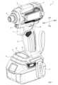
本実施形態のインパクトドライバ1は、ボルトおよびナット等を対象物に固定するために利用される。(First embodiment)
A first embodiment of the present disclosure will be described below with reference to the drawings.
The
インパクトドライバ1は、図1に示すように、工具本体2と、バッテリパック3とを備える。バッテリパック3は、工具本体2に着脱可能に装着されて、工具本体2に電力を供給する。 The
工具本体2は、ハウジング4と、ハンドグリップ5と、チャックスリーブ6と、トリガ7と、バッテリ装着部8と、モード切替スイッチ9と、正逆切替スイッチ10と、操作パネル11とを備える。 The
ハウジング4は、後述するモータ21および打撃機構23等を収容する。
ハンドグリップ5は、ハウジング4の下方に設置される。ハンドグリップ5は、インパクトドライバ1の使用者がハンドグリップ5を片手で把持可能に成形されている。The
A
チャックスリーブ6は、ハウジング4の前方に設置される。チャックスリーブ6は、その前端部に、ドライバビットおよびソケットビット等の各種工具ビットを着脱自在に装着する装着機構を備える。 A
トリガ7は、ハンドグリップ5の上部前方に設置され、インパクトドライバ1の使用者がインパクトドライバ1を駆動するときに操作される。トリガ7は、使用者がハンドグリップ5を把持した状態で、指で引き操作することができるように形成されている。 The
バッテリ装着部8は、ハンドグリップ5の下端部に設置され、バッテリパック3が着脱可能に装着される。
モード切替スイッチ9は、ハンドグリップ5におけるトリガ7の上方に設置される。モード切替スイッチ9は、使用者が、インパクトドライバ1の動作モードを、予め登録した動作モードに1回の操作で切り替えるときに操作される。The
A
正逆切替スイッチ10は、ハンドグリップ5におけるモード切替スイッチ9の後方に設置される。正逆切替スイッチ10は、使用者が、インパクトドライバ1の回転方向を、ねじの締め付け方向である正方向と、正方向に対して逆の方向である逆方向との間で切り替えるときに操作される。 The normal/
操作パネル11は、バッテリ装着部8に設置される。操作パネル11は、インパクトドライバ1の動作モードを、予め設定された複数種類の動作モードの中から設定するときに押下操作される打撃ボタン12および特殊ボタン13を備える。 The
インパクトドライバ1は、図2に示すように、モータ21と、釣鐘状のハンマケース22と、打撃機構23とを備える。モータ21、ハンマケース22および打撃機構23は、ハウジング4内に収容される。 The
ハンマケース22は、モータ21の前方(すなわち、図2の右側)に組み付けられている。
打撃機構23は、ハンマケース22内に収容されている。すなわち、ハンマケース22内には、後端側に中空部が形成されたスピンドル24が同軸で収容されており、ハンマケース22内の後端側に設けられたボールベアリング25が、このスピンドル24の後端外周を回転可能に支持している。The
The
スピンドル24におけるボールベアリング25の前方には、回転軸に対して点対称となるようにして回転可能に支持された2つの遊星歯車を備える遊星歯車機構26が、ハンマケース22の後端側の内周面に形成されたインターナルギヤ27に噛み合っている。 In front of the
また遊星歯車機構26は、モータ21の出力軸21aの先端部に形成されたピニオン21bに噛み合っている。
そして打撃機構23は、スピンドル24と、ハンマ28と、アンビル29と、コイルバネ30とを備える。The
The
ハンマ28は、スピンドル24に対して一体に回転可能に、且つ、スピンドル24の軸方向に沿って移動可能に連結されている。そしてハンマ28は、コイルバネ30により前方へ付勢されている。 The
また、スピンドル24の前端部は、アンビル29の後端に、遊びがある状態で同軸に挿入されることで回転可能に支持されている。
アンビル29は、ハンマ28による回転力および打撃力を受けて軸回りに回転する。アンビル29は、ハウジング4の前端部に設けられた軸受31によって、軸回りに回転可能に且つ軸方向に変位不能に支持されている。また、アンビル29の前端部には、チャックスリーブ6が取り付けられる。The front end of the
The
なお、モータ21の出力軸21a、スピンドル24、ハンマ28、アンビル29およびチャックスリーブ6は互いに同軸上に配置されている。
ハンマ28は、アンビル29に打撃力を与えるための2つの打撃突部28aを備える。2つの打撃突部28aは、ハンマ28の周方向に沿って180°の間隔を隔てて、ハンマ28の前端面から突出するように設置されている。The
The
アンビル29は、ハンマ28の2つの打撃突部28aに対応する2つの打撃アーム29aを備える。2つの打撃アーム29aは、ハンマ28の周方向に沿って180°の間隔を隔てて、アンビル29の後端に設置されている。 The
そして、コイルバネ30の付勢力によってハンマ28が前方へ付勢されることで、ハンマ28の打撃突部28aにおける回転方向に対して垂直な面が、アンビル29の打撃アーム29aにおける回転方向に対して垂直な面に接触するようになる。 The
打撃突部28aと打撃アーム29aとが接触している状態で、モータ21の回転力により遊星歯車機構26を介してスピンドル24が回転すると、ハンマ28がスピンドル24とともに回転し、ハンマ28の回転力が打撃突部28aと打撃アーム29aとを介してアンビル29へ伝達される。 When the
これにより、アンビル29の先端に装着された工具ビットが回転し、ねじ締めが可能となる。
そして、ねじが所定位置まで締め付けられることにより、アンビル29に対して外部から所定値以上のトルクが加わると、そのアンビル29に対するハンマ28のトルクも所定値以上になる。As a result, the tool bit attached to the tip of the
When the screw is tightened to a predetermined position and external torque of a predetermined value or more is applied to the
これにより、ハンマ28がコイルバネ30の付勢力に抗して後方へ変位し、ハンマ28の打撃突部28aがアンビル29の打撃アーム29aを乗り越えるようになる。つまり、ハンマ28の打撃突部28aがアンビル29の打撃アーム29aから一旦外れ、空転する。 As a result, the
このようにハンマ28の打撃突部28aがアンビル29の打撃アーム29aを乗り越えると、ハンマ28は、スピンドル24とともに回転しつつコイルバネ30の付勢力で再び前方へ変位し、ハンマ28の打撃突部28aがアンビル29の打撃アーム29aを回転方向に打撃する。 When the
従って、アンビル29に対して所定値以上のトルクが加わる毎に、そのアンビル29に対してハンマ28による打撃が繰り返し行われる。そして、このようにハンマ28の打撃力がアンビル29に間欠的に加えられることにより、インパクトドライバ1は、ねじを高トルクで増し締めすることができる。 Therefore, every time a torque equal to or greater than a predetermined value is applied to the
トリガスイッチ32は、使用者により引き操作されるトリガ7と、トリガ7の引き操作によりオンまたはオフされるとともにトリガ7の操作量に応じて抵抗値が変化するように構成されたスイッチ本体部33とを備える。 The
モータ21は、図3に示すように、U,V,W各相の電機子巻線を備えた3相ブラシレスモータである。そして工具本体2は、モータ21の回転位置(すなわち、回転角度)を検出する回転センサ41を備える。回転センサ41は、例えば、モータ21の各相に対応して配置される3つのホール素子を備える。ホール素子は、モータ21が所定角度回転する毎に回転検出信号を発生させるホールIC等で構成される。 The
工具本体2は、モータ21を駆動制御するモータ駆動装置50を備える。
トリガスイッチ32のスイッチ本体部33は、トリガ7が引き操作されているときにオン状態となるメインスイッチ61と、トリガ7の引き量を検出する操作量検出部62とを備える。操作量検出部62は、トリガ7の引き量に応じて抵抗値が変化する可変抵抗である。メインスイッチ61および操作量検出部62は、モータ駆動装置50に接続される。The
A switch
工具本体2は、打撃スイッチ63と、特殊スイッチ64とを備える。打撃スイッチ63は、打撃ボタン12が押下操作されているときにオン状態となるスイッチである。特殊スイッチ64は、特殊ボタン13が押下操作されているときにオン状態となるスイッチである。打撃スイッチ63および特殊スイッチ64は、モータ駆動装置50に接続される。 The tool
また、モード切替スイッチ9および正逆切替スイッチ10は、モータ駆動装置50に接続される。
モータ駆動装置50は、駆動回路51、電流検出回路52、位置検出回路53、表示回路54、電源回路55および制御回路56を備える。Also, the
The
駆動回路51は、バッテリパック3から電力供給を受けて、モータ21の各相巻線に電流を流すための回路である。本実施形態では、駆動回路51は、6つのスイッチング素子Q1,Q2,Q3,Q4,Q5,Q6を備える3相フルブリッジ回路として構成されている。本実施形態では、スイッチング素子Q1~Q6はMOSFETである。 The
駆動回路51において、スイッチング素子Q1~Q3は、モータ21の各端子U,V,Wと、バッテリパック3の正極側に接続された電源ラインとの間に、いわゆるハイサイドスイッチとして設けられている。スイッチング素子Q4~Q6は、モータ21の各端子U,V,Wと、バッテリパック3の負極側に接続されたグランドラインとの間に、いわゆるローサイドスイッチとして設けられている。 In the
バッテリパック3の正極側から駆動回路51に至る電力供給経路には、バッテリ電圧の電圧変動を抑制するためのコンデンサC1が設けられている。
駆動回路51からバッテリパック3の負極側に至る電力供給経路には、この経路を導通または遮断するためのスイッチング素子Q7と、電流検出用の抵抗R1とが設けられている。そして電流検出回路52は、抵抗R1の両端電圧を電流検出信号として制御回路56へ出力する。A power supply path from the positive electrode side of the
A power supply path from the
位置検出回路53は、回転センサ41からの検出信号に基づき、モータ21の回転位置を検出する回路であり、回転位置の検出結果を示す検出信号を制御回路56へ出力する。
表示回路54は、制御回路56からの指令に従い、操作パネル11の打撃力モード表示部66および特殊モード表示部67に設けられた複数のLEDを点灯させるための回路である。The
The
電源回路55は、モータ駆動装置50内の各部に電源供給を行うための回路であり、バッテリパック3から電力供給を受けて、所定の電源電圧Vccを生成する。生成された電源電圧Vccは、制御回路56、表示回路54、各種スイッチからの入力経路に設けられたプルアップ抵抗等に供給される。 The
電源回路55は、動作停止時において、メインスイッチ61がオンされることにより起動し、メインスイッチ61、モード切替スイッチ9、打撃ボタン12および特殊ボタン13の操作停止期間が一定時間以上経過すると、動作を停止する。 The
制御回路56は、CPU56a、ROM56bおよびRAM56c等を備えたマイクロコンピュータを中心に構成されている。マイクロコンピュータの各種機能は、CPU56aが非遷移的実体的記録媒体に格納されたプログラムを実行することにより実現される。この例では、ROM56bが、プログラムを格納した非遷移的実体的記録媒体に該当する。また、このプログラムの実行により、プログラムに対応する方法が実行される。なお、CPU56aが実行する機能の一部または全部を、一つあるいは複数のIC等によりハードウェア的に構成してもよい。また、制御回路56を構成するマイクロコンピュータの数は1つでも複数でもよい。なお、ROM56bは、データを書き換え可能な不揮発性メモリである。ROM56bには、各動作モードにおけるモータ21の制御特性等が記憶される。 The
制御回路56は、CPU56aが実行するソフトウェア処理により実現される機能ブロックとして、SW入力部71と、速度指令部72と、表示制御部73と、回転速度演算部74と、PWM生成部75と、モータ駆動制御部76とを備える。 The
SW入力部71は、メインスイッチ61、モード切替スイッチ9、打撃スイッチ63および特殊スイッチ64のオン状態およびオフ状態を検出して、動作モードと、各種LEDの状態(すなわち、点灯状態または消灯状態)とを設定する。SW入力部71は、設定した動作モードを示す情報を、ROM56bに記憶する。SW入力部71は、各種LEDの状態を示すLED状態情報を、表示制御部73へ出力する。 The
速度指令部72は、操作量検出部62からの入力信号に基づきトリガ7の操作量を検出し、トリガ7の操作量に応じた回転速度を指示する回転速度指令をPWM生成部75へ出力する。 The
表示制御部73は、SW入力部71からの入力に従い、表示回路54を介して各種LEDの状態を制御する。
回転速度演算部74は、位置検出回路53からの検出信号に基づき、モータ21の回転速度を算出し、算出結果をPWM生成部75へ出力する。The
The
PWM生成部75は、SW入力部71にて設定された動作モードに対応した制御特性をROM56bから読み出し、読み出した制御特性に従いモータ21を駆動するための制御信号であるPWM信号を生成する。 The
つまり、PWM生成部75は、ROM56bから読み出した制御特性と、速度指令部72から入力される回転速度指令と、回転速度演算部74から入力されるモータ21の回転速度とに基づき、PWM信号を生成する。 That is, the
モータ駆動制御部76は、PWM生成部75にて生成されたPWM信号に従い、駆動回路51を構成する各スイッチング素子Q1~Q6をオンまたはオフさせることで、モータ21の各相巻線に電流を流し、モータ21を回転させる。 The motor
モータ駆動制御部76は、正逆切替スイッチ10からの入力信号に基づき、モータ21の回転方向を切り替える。
次に、打撃ボタン12および特殊ボタン13を介して設定される動作モードについて説明する。The motor
Next, operation modes set via the
インパクトドライバ1では、動作モードとして、「最速」、「強」、「中」、「弱」の4種類の打撃力モードと、「木材」、「テクス薄」、「テクス厚」、「ボルト1」、「ボルト2」、「ボルト3」の7種類の特殊モードとが設定されている。テクスは、登録商標である。 The
これらの動作モードは、モータ21の制御方法を規定する。各動作モードで規定された制御方法を実現するため、ROM56bには、各動作モードでモータ21を制御するのに必要な制御特性が予め記憶されている。 These operating modes define how the
そして、「最速」、「強」、「中」、「弱」の4種類の打撃力モードは、打撃ボタン12を操作することにより、最速→強→中→弱→最速…というように順次切り換え可能である。 By operating the
また、「木材」、「テクス薄」、「テクス厚」、「ボルト1」、「ボルト2」、「ボルト3」の7種類の特殊モードは、特殊ボタン13を操作することで、木材→テクス薄→テクス厚→ボルト1→ボルト2→ボルト3→木材…というように順次切り換え可能である。 In addition, by operating the
図4に示すように、操作パネル11は、打撃ボタン12と、特殊ボタン13と、打撃力モード表示部66と、特殊モード表示部67と、モード表示LED81,82,83,84,85とを備える。 As shown in FIG. 4, the
打撃力モード表示部66および特殊モード表示部67は、表示回路54からの指令に基づいて、モード表示LED81,82,83,84,85を点灯させたり、消灯させたりする。 The impact force
動作モードが「最速」である場合には、モード表示LED81,82,83,84が点灯する。動作モードが「強」である場合には、モード表示LED81,82,83が点灯する。動作モードが「中」である場合には、モード表示LED81,82が点灯する。動作モードが「弱」である場合には、モード表示LED81が点灯する。 When the operation mode is "fastest", the
動作モードが「木材」である場合には、モード表示LED81,85が点灯する。動作モードが「テクス薄」である場合には、モード表示LED82,85が点灯する。動作モードが「テクス厚」である場合には、モード表示LED83,85が点灯する。 When the operation mode is "wood", the
動作モードが「ボルト1」である場合には、モード表示LED81,84,85が点灯する。動作モードが「ボルト2」である場合には、モード表示LED82,84,85が点灯する。動作モードが「ボルト3」である場合には、モード表示LED83,84,85が点灯する。 When the operation mode is "
「最速」、「強」、「中」、「弱」の4種類の打撃力モードでは、打撃力モード毎に、トリガ7の引き量に応じたPWM信号のデューティ比が設定されている。
具体的には、打撃力モードが「最速」である場合には、例えば、トリガ引き量を「1」から「10」までの10段階に分割した際、トリガ引き量が最も大きい「10」であるときにPWM信号のデューティ比が最大となり、モータ21を最速で回転させるように設定される。The duty ratio of the PWM signal is set according to the pulling amount of the
Specifically, when the impact force mode is "fastest", for example, when the trigger pull amount is divided into 10 levels from "1" to "10", "10", which has the largest trigger pull amount, At some point, the duty ratio of the PWM signal becomes maximum, and the
そして、トリガ引き量が「10」であるときにおけるPWM信号のデューティ比は、「最速」、「強」、「中」、「弱」の順で小さくなる。
また、打撃力モードが「最速」、「強」、「中」、「弱」の何れであっても、トリガ引き量が最小である「1」に達したときに、PWM信号のデューティ比が0付近の最小値となる。そして、トリガ引き量が「1」から増加するに従い、トリガ引き量が「10」に達したときのデューティ比まで、徐々に上昇するように設定されている。The duty ratio of the PWM signal when the trigger pull amount is "10" decreases in the order of "fastest", "strong", "medium", and "weak".
Also, regardless of whether the impact force mode is "fastest", "strong", "medium" or "weak", when the trigger pull amount reaches the minimum "1", the duty ratio of the PWM signal is It becomes the minimum value near 0. Then, as the trigger pull amount increases from "1", the duty ratio is set to gradually increase up to the duty ratio when the trigger pull amount reaches "10".
このため、打撃力モードでは、トリガ引き量が「1」以上となる操作範囲が、モータ21を駆動可能な有効操作範囲となり、その有効操作範囲内で、トリガ引き量が「10」に達するまでの領域が、モータ21の回転速度を調整可能な制御範囲となる。 Therefore, in the impact force mode, the operation range in which the trigger pull amount is "1" or more becomes the effective operation range in which the
このため、打撃力モードにおいてトリガ7が引き操作されると、モータ21の回転速度が徐々に増加し、モータ21が無負荷状態であれば、トリガ7の引き量に対応した一定回転速度となる。 Therefore, when the
そして、ねじ締め等によりモータ21に負荷が加わると、その負荷に応じてモータ21の回転速度が低下し、その後、打撃が発生すると、モータ21に加わる負荷が一時的に低下するため、モータ21の回転速度が変動する。 When a load is applied to the
なお、上記説明では、トリガ引き量を10段階に分割して、有効操作範囲および制御範囲を設定した例について説明したが、有効操作範囲および制御範囲は、トリガ7の全操作領域に対し適宜設定すればよく、上記設定方法に限定されるものではない。 In the above description, an example in which the trigger pull amount is divided into 10 stages and the effective operation range and the control range are set is described. The setting method is not limited to the above setting method.
次に、特殊モードのうち、「テクス薄」、「テクス厚」は、被加工材にねじ孔を開けるためのドリルが先端部分に設けられたテクスねじを締め付けるための動作モードである。
「テクス厚」の特殊モードでは、制御回路56は、モータ21の駆動が開始されてから打撃が発生するまで、打撃力モードと同様に、トリガ7の引き量に応じたデューティ比のPWM信号でモータ21を駆動する。但し、トリガ引き量に応じたデューティ比は、「最速」の打撃力モードと一致するように設定されている。Among the special modes, "Thin tex" and "Thick tex" are operation modes for tightening a tex screw having a drill at the tip for drilling a screw hole in the workpiece.
In the "texture thickness" special mode, the
そして、打撃が所定回発生すると、制御回路56は、被加工材にねじ孔が形成されたものと判断して、PWM信号のデューティ比を小さくし、モータ21の回転速度を低下させる。 When the impact occurs a predetermined number of times, the
これにより、インパクトドライバ1は、モータ21の駆動が開始されてから被加工材にねじ孔が形成されるまではモータ21を高速で回転させ、その後、モータ21の回転速度を低下させることができる。このため、インパクトドライバ1の使用者は、ねじ締めを安定して実施できるようになる。 As a result, the
なお、テクスモードでの「テクス薄」と「テクス厚」との違いは、被加工材の厚さである。
「テクス薄」の特殊モードでは、制御回路56は、モータ21の駆動が開始されてから打撃が発生するまで、打撃力モードと同様に、トリガ7の引き量に応じたデューティ比のPWM信号でモータ21を駆動する。但し、トリガ引き量に応じたデューティ比は、「強」の打撃力モードよりもモータ21の回転速度が若干低くなるように設定されている。そして、打撃が所定回発生すると、制御回路56は、モータ21の駆動を停止する。The difference between "tex thin" and "tex thick" in the tex mode is the thickness of the workpiece.
In the "texture light" special mode, the
また、特殊モードのうち、「木材」では、制御回路56は、トリガ7が引き操作されると、その引き量に応じてPWM信号のデューティ比を設定する。なお、このデューティ比は、「最速」の打撃力モードよりも小さくなるように設定される。 In the "wood" mode among the special modes, when the
そして、モータ21の駆動開始後、打撃が所定回発生すると、制御回路56は、PWM信号のデューティ比を徐々に増加させる。これは、木材へねじを固定する場合において、モータ21の駆動開始直後には、ねじは木材に食い込んでいないため、ねじをゆっくりと回転させて、木材に食い込ませる必要があるためである。 After the start of driving the
つまり、「木材」の特殊モードでは、制御回路56は、モータ21の駆動開始後にモータ21を低回転速度で駆動し、その後、所定回打撃が発生すると、ねじが木材に食い込んだものとして、モータ21の回転を徐々に増加させる。この結果、インパクトドライバ1の使用者は、木材へのねじの固定および締め付けを短時間で効率よく実施できるようになる。 In other words, in the "wood" special mode, the
特殊モードのうち、「ボルト1」、「ボルト2」、「ボルト3」は、ボルトまたはナットの締め付け若しくは取り外しを行うための動作モードである。以下、「ボルト1」、「ボルト2」、「ボルト3」の特殊モードをまとめて、ボルトモードという。 Of the special modes, "
すなわち、モータ21を回転させてボルトの締め付け若しくは取り外しを行う際には、工具ビットをボルトの頭部に嵌めるため、ねじを締め付けるときのように、工具ビットがボルトから外れることはない。 That is, when the
このため、ボルトモードでは、PWM信号のデューティ比が最大となるトリガ引き量が、打撃力モードでの引き量に比べて小さくなるように、制御特性が設定されている。
つまり、ボルトモードでは、トリガ引き量が「4」以上でPWM信号のデューティ比が最大となるように、モータ21の制御特性が設定されている。Therefore, in the bolt mode, the control characteristics are set so that the trigger pull amount that maximizes the duty ratio of the PWM signal is smaller than the pull amount in the impact force mode.
That is, in the volt mode, the control characteristics of the
また、ボルトモードでは、ボルトの締め付け若しくは取り外しを速やかに実施できるようにするため、トリガ引き量が「4」以上になったときのPWM信号のデューティ比は、「最速」の打撃力モードと同じ若しくは略同じ最大値に設定されている。 In addition, in the bolt mode, in order to be able to tighten or remove the bolt quickly, the duty ratio of the PWM signal when the trigger pull amount is "4" or more is the same as the "fastest" impact force mode. Alternatively, they are set to approximately the same maximum value.
このため、ボルトモードでは、最速の動作モードに比べ、トリガ7を少し引いただけで、モータ21が最速で回転することになり、インパクトドライバ1の使用者は、ボルトの締め付け若しくは取り外しを短時間で効率よく行うことができることになる。 Therefore, in the bolt mode, even if the
また使用者は、トリガ7を最大引き量付近まで引き操作することなく、モータ21を高速回転させることができる。このため、インパクトドライバ1は、使用者が、ボルトの締め付け若しくは取り外し作業を行う際に、トリガ7の操作によって使用者の指が疲労し、長時間、作業を継続することができなくなるという事態の発生を抑制することができる。 Further, the user can rotate the
また、ボルトモードにおいて、モータ21を逆回転させて、ボルト若しくはナットの締め付けを緩める際には、モータ21の駆動を開始すると、ボルト若しくはナットから負荷が加わるので、直ぐに打撃が発生する。 In the bolt mode, when the
そして、その打撃によって、ボルト若しくはナットの締め付けが緩むと、モータ21に加わる負荷が低下し、モータ21の回転速度が上昇する。
そこで、ボルトモードにおいて、モータ21の逆回転時には、モータ21の駆動を開始してから、打撃が検出され、その後、所定時間打撃が検出されなくなると、モータ21の駆動を停止若しくは低減させるように、制御特性が設定される。When the bolt or nut is loosened by the impact, the load applied to the
Therefore, in the bolt mode, when the
このため、インパクトドライバ1は、ボルト若しくはナットの締め付けを緩める際には、モータ21を必要以上に回転させてボルト若しくはナットが工具ビットから落下するのを抑制できる。 Therefore, when the bolt or nut is loosened, the
「ボルト1」の特殊モードでは、制御回路56は、モータ21の正回転時において、モータ21の駆動が開始されてから打撃が発生するまで、2500[/分]の回転速度でモータ21を駆動する。そして、打撃が所定回発生すると、制御回路56は、モータ21の駆動を停止する。 In the "
「ボルト1」の特殊モードでは、制御回路56は、モータ21の逆回転時において、まず、2500[/分]の回転速度でモータ21を駆動する。そして、打撃が検出され、その後、所定時間打撃が検出されなくなると、制御回路56は、モータ21が2回転してから、モータ21の駆動を停止する。 In the "
「ボルト2」の特殊モードでは、制御回路56は、モータ21の正回転時において、モータ21の駆動が開始されてから打撃が発生するまで、「最速」の打撃力モードと同様にしてモータ21を駆動する。そして、打撃が所定回発生した後に打撃が0.3秒間継続すると、制御回路56は、モータ21の駆動を停止する。 In the "
「ボルト2」の特殊モードでは、制御回路56は、モータ21の逆回転時において、まず、「最速」の打撃力モードと同様にしてモータ21を駆動する。そして、打撃が検出され、その後、所定時間打撃が検出されなくなると、制御回路56は、モータ21が2回転してから、モータ21の駆動を停止する。 In the "
「ボルト3」の特殊モードでは、制御回路56は、モータ21の正回転時において、モータ21の駆動が開始されてから打撃が発生するまで、「最速」の打撃力モードと同様にしてモータ21を駆動する。そして、打撃が所定回発生した後に打撃が1秒間継続すると、制御回路56は、モータ21の駆動を停止する。 In the "
「ボルト3」の特殊モードでは、制御回路56は、モータ21の逆回転時において、まず、「最速」の打撃力モードと同様にしてモータ21を駆動する。そして、打撃が検出され、その後、所定時間打撃が検出されなくなると、制御回路56は、モータ21の回転速度を250[/分]まで急速に低下させる。 In the "
ROM56bには、図5に示すように、トリガ引き量に応じて目標回転速度およびデューティ比を設定するための設定テーブル90が記憶されている。
設定テーブル90は、「最速」、「強」、「中」、「弱」の打撃力モードのそれぞれについて、打撃前の目標回転速度、打撃前のPWMデューティ比、打撃後の目標回転速度および打撃後のPWMデューティ比とトリガ引き量との対応関係を設定している。As shown in FIG. 5, the
The setting table 90 stores the target rotation speed before impact, the PWM duty ratio before impact, the target rotation speed after impact, and the impact power mode for each of the “fastest”, “strong”, “medium”, and “weak” impact power modes. A corresponding relationship is set between the subsequent PWM duty ratio and the amount of trigger pull.
なお、図5には示していないが、設定テーブル90は、「木材」、「テクス薄」、「テクス厚」、「ボルト1」、「ボルト2」、「ボルト3」の特殊モードのそれぞれについても、打撃前の目標回転速度、打撃前のPWMデューティ比、打撃後の目標回転速度および打撃後のPWMデューティ比とトリガ引き量との対応関係を設定している。 Although not shown in FIG. 5, the setting table 90 has special modes of "wood", "thin text", "thick text", "
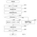
次に、制御回路56のCPU56aが実行する工具制御処理の手順を説明する。工具制御処理は、制御回路56に電源電圧Vccが供給されて制御回路56が起動した後に開始される処理である。 Next, the procedure of tool control processing executed by the
工具制御処理が実行されると、CPU56aは、図6に示すように、まずS10にて、現在設定されている動作モードを示す現在モード情報をROM56bから読み出す。
そしてCPU56aは、S20にて、モード切替操作が行われたか否かを判断する。モード切替操作は、モード切替スイッチ9、打撃ボタン12および特殊ボタン13に対する操作である。When the tool control process is executed, the
Then, in S20, the
ここで、モード切替操作が行われていない場合には、CPU56aは、S40に移行する。一方、モード切替スイッチ9が操作された場合には、CPU56aは、S30にて、現在設定されている動作モードと、検出されたモード切替操作とに基づいて、動作モードを変更し、変更した動作モードを示す情報を現在モード情報としてROM56bに記憶し、S40に移行する。 Here, if the mode switching operation has not been performed, the
そして、S40に移行すると、CPU56aは、メインスイッチ61からの入力信号に基づき、トリガ7が操作されているか否かを判断する。ここで、トリガ7が操作されていない場合には、CPU56aは、S20に移行する。 After proceeding to S40, the
一方、トリガ7が操作されている場合には、CPU56aは、S50にて、操作量検出部62からの入力信号に基づきトリガ7の引き量を検出する。さらにCPU56aは、S60にて、現在の動作モードとトリガ7の引き量とに対応する打撃前の目標回転速度と、現在の動作モードとトリガ7の引き量とに対応する打撃後の目標回転速度とを、設定テーブル90から取得する。 On the other hand, when the
そしてCPU56aは、S70にて、打撃検出処理を実行する。打撃検出処理では、CPU56aは、まず、回転センサ41からの検出信号により得られるモータ21の回転速度の予め設定された増減判定時間内における増減量が、予め設定された打撃判定値以上であるか否かを判断する。本実施形態では、増減判定時間は例えば50[ms]に設定され、打撃判定値は例えば100[/分]に設定されている。 Then, the
ここで、増減判定時間内における増減量が打撃判定値未満である場合には、CPU56aは、打撃検出処理を終了する。
一方、増減判定時間内における増減量が打撃判定値以上である場合には、CPU56aは、RAM56cに設けられた打撃カウンタをインクリメント(すなわち、1加算)する。なお、打撃カウンタは、トリガ7が操作されている状態から、トリガ7が操作されていない状態へ移行した時点で、リセット(すなわち、0に設定)される。Here, if the increase/decrease amount within the increase/decrease determination time is less than the impact determination value, the
On the other hand, when the increase/decrease amount within the increase/decrease determination time is equal to or greater than the impact determination value, the
次にCPU56aは、打撃カウンタの値が予め設定された打撃判定回数以上であるか否かを判断する。ここで、打撃カウンタの値が打撃判定回数未満である場合には、CPU56aは、打撃検出処理を終了する。 Next, the
一方、打撃カウンタの値が打撃判定回数以上である場合には、CPU56aは、RAM56cに設けられた打撃検出フラグをセットして、打撃検出処理を終了する。なお、打撃検出フラグは、トリガ7が操作されている状態から、トリガ7が操作されていない状態へ移行した時点で、クリアされる。 On the other hand, when the value of the impact counter is equal to or greater than the number of impact determination times, the
そして、打撃検出処理が終了すると、CPU56aは、S80にて、打撃を検出したか否かを判断する。具体的には、CPU56aは、打撃検出フラグがセットされているか否かを判断し、打撃検出フラグがセットされている場合には、打撃を検出したと判断し、打撃検出フラグがクリアされている場合には、打撃を検出していないと判断する。 When the impact detection process ends, the
ここで、打撃を検出していない場合には、CPU56aは、S90にて、P制御処理を実行し、S40に移行する。一方、打撃を検出した場合には、CPU56aは、S100にて、PI制御処理を実行し、S40に移行する。 Here, if the impact is not detected, the
次に、S90でCPU56aが実行するP制御処理の手順を説明する。
P制御処理が実行されると、CPU56aは、図7に示すように、まずS210にて、基本デューティ比を取得する。具体的には、CPU56aは、現在の動作モードと、S50で検出したトリガ引き量とに対応する打撃前のPWMデューティ比を、設定テーブル90から取得する。そしてCPU56aは、取得したPWMデューティ比を示す値を、RAM56cに設けられた基本デューティ比BaseDutyに格納する。Next, the procedure of the P control process executed by the
When the P control process is executed, the
次にCPU56aは、S220にて、回転速度差を算出する。具体的には、CPU56aは、S60で取得した打撃前の目標回転速度と、回転センサ41からの検出信号により得られるモータ21の回転速度(以下、現在の実回転速度)との差を算出し、この差を、RAM56cに設けられた回転速度差Diffに格納する。 Next, in S220, the
さらにCPU56aは、S230にて、比例補正量を算出する。具体的には、CPU56aは、回転速度差Diffに格納されている値と、予め設定されている比例ゲインGain_Pとを乗算した乗算値を、RAM56cに設けられた比例補正量Offset_Pに格納する。本実施形態では、比例ゲインGain_Pは例えば0.01に設定されている。 Further, the
そしてCPU56aは、S240にて、出力デューティ比を算出して、P制御処理を終了する。具体的には、CPU56aは、基本デューティ比BaseDutyに格納されている値と、比例補正量Offset_Pに格納されている値とを加算した加算値を、RAM56cに設けられた出力デューティ比Outputに格納する。 Then, in S240, the
次に、S100でCPU56aが実行するPI制御処理の手順を説明する。
PI制御処理が実行されると、CPU56aは、図8に示すように、まずS310にて、基本デューティ比を取得する。具体的には、CPU56aは、現在の動作モードと、S50で検出したトリガ引き量とに対応する打撃後のPWMデューティ比を、設定テーブル90から取得する。そしてCPU56aは、取得したPWMデューティ比を示す値を基本デューティ比BaseDutyに格納する。Next, the procedure of PI control processing executed by the
When the PI control process is executed, the
次にCPU56aは、S320にて、回転速度差を算出する。具体的には、CPU56aは、S60で取得した打撃後の目標回転速度と、現在の実回転速度との差を算出し、この差を回転速度差Diffに格納する。 Next, the
さらにCPU56aは、S330にて、比例補正量を算出する。具体的には、CPU56aは、回転速度差Diffに格納されている値と比例ゲインGain_Pとを乗算した乗算値を比例補正量Offset_Pに格納する。 Further, the
そしてCPU56aは、S340にて、累積差を算出する。具体的には、CPU56aは、RAM56cに設けられた累積差Diff_integralに格納されている値と、回転速度差Diffに格納されている値とを加算した加算値を、累積差Diff_integralに格納する。 The
次にCPU56aは、S350にて、累積補正量を算出する。具体的には、CPU56aは、累積差Diff_integralに格納されている値と、予め設定されている累積ゲインGain_Iとを乗算した乗算値を、RAM56cに設けられた累積補正量Offset_Iに格納する。 Next, the
そしてCPU56aは、S360にて、出力デューティ比を算出して、PI制御処理を終了する。具体的には、CPU56aは、基本デューティ比BaseDutyに格納されている値と、比例補正量Offset_Pに格納されている値と、累積補正量Offset_Iに格納されている値とを加算した加算値を、出力デューティ比Outputに格納する。 Then, in S360, the
図9は、モータ21の駆動が開始されてから打撃を検出した後までにおけるモータ回転速度およびデューティ比の変化を示すグラフである。
図9における時刻t0は、モータ21の駆動が開始されたタイミングである。時刻t3は、モータ21に負荷が掛かり始めたタイミングである。時刻t4は、打撃が開始されたタイミングである。時刻t5は、制御回路56が打撃を検出したタイミングである。FIG. 9 is a graph showing changes in motor rotation speed and duty ratio from when the
Time t0 in FIG. 9 is the timing when the driving of the
線L1は、制御回路56が打撃を検出するまでは基本デューティ比BD1でPWM制御を実行し、制御回路56が打撃を検出した後にPI制御処理を実行する場合におけるデューティ比を示す。 A line L1 indicates the duty ratio when the PWM control is performed with the basic duty ratio BD1 until the
線L2は、制御回路56が打撃を検出するまでは基本デューティ比BD1を用いたP制御処理を実行し、制御回路56が打撃を検出した後にPI制御処理を実行する場合におけるデューティ比を示す。 A line L2 indicates the duty ratio when the P control process using the basic duty ratio BD1 is executed until the
線L3は、制御回路56が打撃を検出するまでは、基本デューティ比BD1より小さい基本デューティ比BD2を用いたP制御処理を実行し、制御回路56が打撃を検出した後にPI制御処理を実行する場合におけるデューティ比を示す。 The line L3 executes P control processing using a basic duty ratio BD2 smaller than the basic duty ratio BD1 until the
線L1で示すデューティ比は、時刻t0から時刻t2までは基本デューティ比BD1になるまで直線的に増加し、時刻t2から時刻t5までは基本デューティ比BD1を維持し、時刻t5以降は振動しながら徐々に増加している。 The duty ratio indicated by the line L1 increases linearly from time t0 to time t2 until reaching the basic duty ratio BD1, maintains the basic duty ratio BD1 from time t2 to time t5, and vibrates after time t5. Gradually increasing.
線L2で示すデューティ比は、時刻t0から時刻t2までは基本デューティ比BD1になるまで直線的に増加し、時刻t2から時刻t3までは基本デューティ比BD1を維持し、時刻t3から時刻t4までは直線的に増加し、時刻t4以降は振動しながら徐々に増加している。 The duty ratio indicated by the line L2 increases linearly from time t0 to time t2 until reaching the basic duty ratio BD1, maintains the basic duty ratio BD1 from time t2 to time t3, and continues from time t3 to time t4. It increases linearly and gradually increases after time t4 while oscillating.
線L3で示すデューティ比は、時刻t0から時刻t1までは基本デューティ比BD2になるまで直線的に増加し、時刻t1から時刻t3までは基本デューティ比BD2を維持し、時刻t3から時刻t4までは直線的に増加し、時刻t4以降は振動しながら徐々に増加している。なお、線L3で示すデューティ比における時刻t3から時刻t4までの増加率は、線L2で示すデューティ比における時刻t3から時刻t4までの増加率より大きい。 The duty ratio indicated by the line L3 increases linearly from time t0 to time t1 until reaching the basic duty ratio BD2, maintains the basic duty ratio BD2 from time t1 to time t3, and continues from time t3 to time t4. It increases linearly and gradually increases after time t4 while oscillating. Note that the rate of increase in the duty ratio indicated by line L3 from time t3 to time t4 is greater than the rate of increase in the duty ratio indicated by line L2 from time t3 to time t4.
線L11は、線L1で示すデューティ比でPWM制御を実行した場合におけるモータ回転速度を示す。
線L12は、線L2で示すデューティ比でPWM制御を実行した場合におけるモータ回転速度を示す。A line L11 indicates the motor rotation speed when the PWM control is performed with the duty ratio indicated by the line L1.
A line L12 indicates the motor rotation speed when the PWM control is performed with the duty ratio indicated by the line L2.
線L13は、線L3で示すデューティ比でPWM制御を実行した場合におけるモータ回転速度を示す。
線L11で示すモータ回転速度は、時刻t0から時刻t3までの間に打撃前目標回転速度TG1に達し、時刻t3から時刻t4までは直線的に低下する。さらに、線L11で示すモータ回転速度は、時刻t4から時刻t5までの間に振動しながら徐々に低下し、時刻t5で打撃後目標回転速度TG3を若干下回る。そして、線L11で示すモータ回転速度は、時刻t5から時刻t6までの間に振動しながら徐々に増加し、時刻t6で打撃後目標回転速度TG3に達する。さらに、線L11で示すモータ回転速度は、時刻t6以降は振動しながら打撃後目標回転速度TG3の近傍を維持する。A line L13 indicates the motor rotation speed when the PWM control is performed with the duty ratio indicated by the line L3.
The motor rotation speed indicated by line L11 reaches the pre-impact target rotation speed TG1 between time t0 and time t3, and decreases linearly between time t3 and time t4. Further, the motor rotation speed indicated by line L11 gradually decreases while oscillating from time t4 to time t5, and at time t5, it falls slightly below the post-impact target rotation speed TG3. Then, the motor rotation speed indicated by the line L11 gradually increases while oscillating from time t5 to time t6, and reaches the post-impact target rotation speed TG3 at time t6. Furthermore, the motor rotation speed indicated by the line L11 maintains the vicinity of the post-impact target rotation speed TG3 while vibrating after time t6.
線L12で示すモータ回転速度は、時刻t0から時刻t3までの間に打撃前目標回転速度TG1に達し、時刻t3から時刻t4までは直線的に低下する。なお、線L12で示すモータ回転速度における時刻t3から時刻t4までの低下率は、線L11で示すモータ回転速度における時刻t3から時刻t4までの低下率より小さい。 The motor rotation speed indicated by line L12 reaches the pre-impact target rotation speed TG1 between time t0 and time t3, and decreases linearly between time t3 and time t4. Note that the rate of decrease in the motor rotation speed indicated by line L12 from time t3 to time t4 is smaller than the rate of decrease in the motor rotation speed indicated by line L11 from time t3 to time t4.
さらに、線L12で示すモータ回転速度は、時刻t4から時刻t5までの間に振動しながら徐々に低下し、時刻t5において打撃後目標回転速度TG3近傍で振動する。さらに、線L12で示すモータ回転速度は、時刻t5以降は振動しながら打撃後目標回転速度TG3の近傍を維持する。 Furthermore, the motor rotation speed indicated by line L12 gradually decreases while oscillating from time t4 to time t5, and oscillates near the post-impact target rotation speed TG3 at time t5. Furthermore, the motor rotation speed indicated by the line L12 maintains the vicinity of the post-impact target rotation speed TG3 while vibrating after time t5.
線L13で示すモータ回転速度は、時刻t0から時刻t3までの間に、打撃前目標回転速度TG1より低い打撃前目標回転速度TG2に達し、時刻t3から時刻t4までは直線的に低下する。なお、線L13で示すモータ回転速度における時刻t3から時刻t4までの低下率は、線L12で示すモータ回転速度における時刻t3から時刻t4までの低下率より小さい。 The motor rotation speed indicated by the line L13 reaches the pre-impact target rotation speed TG2 lower than the pre-impact target rotation speed TG1 from time t0 to time t3, and decreases linearly from time t3 to time t4. Note that the rate of decrease in the motor rotation speed indicated by line L13 from time t3 to time t4 is smaller than the rate of decrease in the motor rotation speed indicated by line L12 from time t3 to time t4.
さらに、線L13で示すモータ回転速度は、時刻t4から時刻t5までの間に振動しながら徐々に低下し、時刻t5において打撃後目標回転速度TG3近傍で振動する。さらに、線L13で示すモータ回転速度は、時刻t5以降は振動しながら打撃後目標回転速度TG3の近傍を維持する。
なお、線L11,L12で示すモータ回転速度と、線L13で示すモータ回転速度とは、打撃前の基本デューティ比が互いに異なる。このため、実際には、線L11,L12で示すモータ回転速度と、線L13で示すモータ回転速度とでは、打撃が開始されるタイミング(すなわち、時刻t4)が異なる。しかし、図9では、線L1,L2で示すデューティ比と、線L13で示すデューティ比とを比較し易くするため、更に、線L11,L12で示すモータ回転速度と、線L13で示すモータ回転速度とを比較し易くするために、打撃が開始されるタイミング(すなわち、時刻t4)を一致させている。Furthermore, the motor rotation speed indicated by line L13 gradually decreases while oscillating from time t4 to time t5, and oscillates near the post-impact target rotation speed TG3 at time t5. Further, the motor rotation speed indicated by the line L13 maintains the vicinity of the post-impact target rotation speed TG3 while vibrating after time t5.
Note that the motor rotation speed indicated by lines L11 and L12 and the motor rotation speed indicated by line L13 differ from each other in the basic duty ratio before hitting. Therefore, in practice, the motor rotation speed indicated by the lines L11 and L12 and the motor rotation speed indicated by the line L13 differ from each other in timing at which impact is started (that is, time t4). However, in FIG. 9, in order to facilitate comparison between the duty ratio indicated by lines L1 and L2 and the duty ratio indicated by line L13, the motor rotation speed indicated by lines L11 and L12 and the motor rotation speed indicated by line L13 are added. In order to facilitate comparison, the timing at which the hitting is started (that is, time t4) is matched.
このように構成されたインパクトドライバ1は、モータ21と、打撃機構23と、制御回路56とを備える。
打撃機構23は、ハンマ28と、アンビル29とを備え、アンビル29に対して外部から所定値以上のトルクが加わると、ハンマ28がアンビル29から外れて空転し、アンビル29を回転方向に打撃する。ハンマ28は、モータ21の回転力によって回転する。アンビル29は、ハンマ28の回転力を受けて回転し工具ビットが装着される。The
The
制御回路56は、ハンマ28によるアンビル29の打撃を検出する。制御回路56は、モータ21への通電電流に対してPWM制御を実行することによりモータ21を制御する。 The
そして制御回路56は、モータ21の駆動を開始してから、打撃を検出するまでの間において、基本デューティ比に、打撃前目標回転速度とモータ回転速度との回転速度差に比例した比例補正量のみを加算した出力デューティ比でPWM制御を実行する。基本デューティ比は、打撃前目標回転速度に応じて設定される。
また制御回路56は、打撃を検出した後において、モータ回転速度が、モータ回転速度の目標値として打撃前目標回転速度とは別に設定された打撃後目標回転速度で一定となるようにモータ21への通電電流を制御するPI制御処理(以下、打撃後定回転制御)を実行する。The
In addition, the
このようにインパクトドライバ1は、打撃検出前の打撃前目標回転速度とモータ回転速度との回転速度差に比例した比例補正量のみを基本デューティ比に加算した出力デューティ比でモータ21を制御する。これにより、インパクトドライバ1は、打撃検出前におけるモータ回転速度の低下を抑制することができ、打撃検出時において、打撃検出後の打撃後目標回転速度とモータ回転速度との回転速度差を小さくすることができる。このため、インパクトドライバ1は、打撃検出前後でのモータ回転速度の変動を抑制し、インパクトドライバ1の使用感を向上させることができる。 Thus, the
さらにインパクトドライバ1は、打撃検出前にはモータ回転速度が低下し打撃検出後にはモータ回転速度が上昇するという動作の発生を抑制し、使用感を向上させることができる。 Furthermore, the
以上説明した実施形態において、インパクトドライバ1は回転打撃工具に相当し、工具ビットは工具要素に相当し、S70は打撃検出部としての処理に相当し、制御回路56は制御部に相当する。 In the embodiment described above, the
また、比例補正量は比例デューティ比に相当し、出力デューティ比は加算デューティ比に相当し、PI制御処理は打撃後定回転制御に相当する。
(第2実施形態)
以下に本開示の第2実施形態を図面とともに説明する。なお第2実施形態では、第1実施形態と異なる部分を説明する。共通する構成については同一の符号を付す。Further, the proportional correction amount corresponds to the proportional duty ratio, the output duty ratio corresponds to the addition duty ratio, and the PI control process corresponds to post-impact constant rotation control.
(Second embodiment)
A second embodiment of the present disclosure will be described below with reference to the drawings. In addition, in the second embodiment, portions different from the first embodiment will be described. The same code|symbol is attached|subjected about a common structure.
第2実施形態のインパクトドライバ1は、P制御処理の手順が変更された点が第1実施形態と異なる。
第2実施形態のP制御処理は、図10に示すように、S222,S224,S226,S228の処理が追加された点が第1実施形態と異なる。The
The P control process of the second embodiment differs from that of the first embodiment in that the processes of S222, S224, S226, and S228 are added as shown in FIG.
すなわち、S220の処理が終了すると、CPU56aは、S222にて、目標回転速度差を算出する。具体的には、CPU56aは、S60で取得した打撃前の目標回転速度から、S60で取得した打撃後の目標回転速度を減算した減算値を、RAM56cに設けられた目標回転速度差Target_Diffに格納する。 That is, when the processing of S220 ends, the
そしてCPU56aは、S224にて、目標回転速度差が0より大きいか否かを判断する。具体的には、CPU56aは、目標回転速度差Target_Diffに格納されている値が0より大きいか否かを判断する。 Then, the
ここで、目標回転速度差が0以下である場合には、CPU56aは、S226にて、基準比例ゲインを比例ゲインに設定して、S230に移行する。具体的には、CPU56aは、RAM56cに設けられた比例ゲインGain_Pに、予め設定された基準比例ゲインBaseGain_Pの値を格納する。 Here, if the target rotation speed difference is 0 or less, the
一方、目標回転速度差が0より大きい場合には、CPU56aは、S228にて、目標回転速度差から比例ゲインを算出して、S230に移行する。具体的には、CPU56aは、基準比例ゲインBaseGain_Pの値を、目標回転速度差Target_Diffに格納されている値で除算した除算値を、比例ゲインGain_Pに格納する。 On the other hand, if the target rotation speed difference is greater than 0, the
このように構成されたインパクトドライバ1では、制御回路56は、打撃前目標回転速度と、打撃後目標回転速度との差に応じて、比例補正量を変化させる。これにより、インパクトドライバ1は、打撃前目標回転速度と打撃後目標回転速度との差に応じて、打撃検出後の目標回転速度とモータ回転速度との回転速度差を小さくすることができる。 In the
また制御回路56は、打撃前目標回転速度と打撃後目標回転速度との間の差が小さいほど比例補正量が大きくなるように比例補正量を変化させる。これにより、インパクトドライバ1は、打撃前目標回転速度と打撃後目標回転速度との間の差が小さいほど、打撃検出前におけるモータ回転速度の低下を抑制することができ、打撃検出時において、打撃検出後の目標回転速度とモータ回転速度との回転速度差を小さくすることができる。 Further, the
(第3実施形態)
以下に本開示の第3実施形態を図面とともに説明する。なお第3実施形態では、第1実施形態と異なる部分を説明する。共通する構成については同一の符号を付す。(Third Embodiment)
A third embodiment of the present disclosure will be described below with reference to the drawings. Note that in the third embodiment, portions different from the first embodiment will be described. The same code|symbol is attached|subjected about a common structure.
第3実施形態のインパクトドライバ1は、工具制御処理の手順が変更された点が第1実施形態と異なる。
第3実施形態の工具制御処理は、図11に示すように、S72,S74の処理が追加された点が第1実施形態と異なる。The
The tool control process of the third embodiment differs from that of the first embodiment in that the processes of S72 and S74 are added as shown in FIG.
すなわち、S70の処理が終了すると、CPU56aは、S72にて、目標回転速度差を算出する。具体的には、CPU56aは、S60で取得した打撃前の目標回転速度から、S60で取得した打撃後の目標回転速度を減算した減算値を、RAM56cに設けられた目標回転速度差Target_Diffに格納する。 That is, when the process of S70 ends, the
そしてCPU56aは、S74にて、目標回転速度差が0であるか否かを判断する。具体的には、CPU56aは、目標回転速度差Target_Diffに格納されている値が0であるか否かを判断する。 Then, the
ここで、目標回転速度差が0でない場合には、CPU56aは、S80に移行する。一方、目標回転速度差が0である場合には、CPU56aは、S100に移行する。
このように構成されたインパクトドライバ1では、制御回路56は、打撃前目標回転速度と打撃後目標回転速度との間の差が0である場合には、打撃を検出する前において、モータ回転速度が一定となるようにモータ21への通電電流を制御するPI制御処理(以下、打撃前定回転制御)を実行する。これにより、インパクトドライバ1は、打撃前目標回転速度と打撃後目標回転速度との間の差が0である場合には、打撃検出前後でモータ制御方法を切り替えずに定回転制御することで使用感を向上できる。Here, if the target rotation speed difference is not 0, the
In the
以上説明した実施形態において、PI制御処理は打撃前定回転制御に相当する。
(第4実施形態)
以下に本開示の第4実施形態を図面とともに説明する。なお第4実施形態では、第1実施形態と異なる部分を説明する。共通する構成については同一の符号を付す。In the embodiments described above, the PI control process corresponds to pre-impact constant rotation control.
(Fourth embodiment)
A fourth embodiment of the present disclosure will be described below with reference to the drawings. In addition, in the fourth embodiment, portions different from the first embodiment will be described. The same code|symbol is attached|subjected about a common structure.
第4実施形態のインパクトドライバ1は、工具制御処理の手順が変更された点が第1実施形態と異なる。
第4実施形態の工具制御処理は、図12に示すように、S76の処理が追加された点が第1実施形態と異なる。The
The tool control process of the fourth embodiment differs from that of the first embodiment in that the process of S76 is added as shown in FIG.
すなわち、S70の処理が終了すると、CPU56aは、S76にて、トリガ7の引き量が予め設定された制御切替判定値以下であるか否かを判断する。
ここで、トリガ7の引き量が制御切替判定値を超えている場合には、CPU56aは、S80に移行する。一方、トリガ7の引き量が制御切替判定値以下である場合には、CPU56aは、S100に移行する。That is, when the process of S70 ends, the
Here, when the pulling amount of the
このように構成されたインパクトドライバ1は、使用者により操作されるように構成されたトリガ7を備え、制御回路56は、トリガ7の引き量に応じてモータ回転速度が変化するようにモータ21を制御する。そして制御回路56は、トリガ7の引き量が制御切替判定値以下である場合には、打撃を検出する前において、モータ回転速度が一定となるようにモータ21への通電電流を制御する打撃前定回転制御を実行する。これにより、インパクトドライバ1は、トリガ7の引き量が制御切替判定値以下である場合には、打撃検出前後でモータ制御方法を切り替えずに定回転制御することで使用感を向上できる。 The
以上説明した実施形態において、トリガ7は操作部に相当し、引き量は操作量に相当し、PI制御処理は打撃前定回転制御に相当する。
以上、本開示の一実施形態について説明したが、本開示は上記実施形態に限定されるものではなく、種々変形して実施することができる。In the above-described embodiment, the
An embodiment of the present disclosure has been described above, but the present disclosure is not limited to the above embodiment, and can be implemented in various modifications.
例えば上記第3、第4実施形態では、打撃検出前後で定回転制御を実行する形態を示したが、打撃前定回転制御と、打撃後定回転制御とで、比例ゲインを変化させるようにしてもよい。これにより、インパクトドライバ1は、打撃を検出する前と後とで、それぞれの状況に応じた適切なPI制御処理を実行することができる。 For example, in the above-described third and fourth embodiments, constant rotation control is executed before and after the impact is detected. good too. As a result, the
さらに、打撃前定回転制御における比例ゲインは、打撃後定回転制御における比例ゲインより大きいようにしてもよい。これにより、インパクトドライバ1は、打撃を検出する前においてモータ回転速度を一定に維持し易くすることができるとともに、打撃を検出した後においてモータ21への通電電流の振動振幅の増大を抑制することができる。
上記実施形態では、打撃力モードと特殊モードとで同じモード表示LED81~85を使用して表示する形態を示したが、打撃力モードと特殊モードとで別のLEDを点灯させたり、色を変えて点灯させたりするようにしてもよい。Furthermore, the proportional gain in the pre-impact constant rotation control may be larger than the proportional gain in the post-impact constant rotation control. As a result, the
In the above embodiment, the same
上記実施形態における1つの構成要素が有する複数の機能を、複数の構成要素によって実現したり、1つの構成要素が有する1つの機能を、複数の構成要素によって実現したりしてもよい。また、複数の構成要素が有する複数の機能を、1つの構成要素によって実現したり、複数の構成要素によって実現される1つの機能を、1つの構成要素によって実現したりしてもよい。また、上記実施形態の構成の一部を省略してもよい。また、上記実施形態の構成の少なくとも一部を、他の上記実施形態の構成に対して付加または置換してもよい。 A plurality of functions possessed by one component in the above embodiment may be implemented by a plurality of components, or a function possessed by one component may be implemented by a plurality of components. Also, a plurality of functions possessed by a plurality of components may be realized by a single component, or a function realized by a plurality of components may be realized by a single component. Also, part of the configuration of the above embodiment may be omitted. Also, at least part of the configuration of the above embodiment may be added or replaced with respect to the configuration of the other above embodiment.
上述したインパクトドライバ1の他、制御回路56としてコンピュータを機能させるためのプログラム、このプログラムを記録した半導体メモリ等の非遷移的実態的記録媒体、工具制御方法など、種々の形態で本開示を実現することもできる。 In addition to the
1…インパクトドライバ、21…モータ、23…打撃機構、28…ハンマ、29…アンビル、56…制御回路 DESCRIPTION OF
Claims (7)
Translated fromJapanese前記モータの回転力によって回転するハンマと、前記ハンマの回転力を受けて回転し工具要素が装着されるアンビルとを備え、前記アンビルに対して外部から所定値以上のトルクが加わると、前記ハンマが前記アンビルから外れて空転し、前記アンビルを回転方向に打撃する打撃機構と、
前記ハンマによる前記アンビルの打撃を検出するように構成された打撃検出部と、
前記モータへの通電電流に対してPWM制御を実行することにより前記モータを制御するように構成された制御部と
を備え、
前記制御部は、
前記モータの駆動を開始してから、前記打撃検出部が前記打撃を検出するまでの間において、前記モータの回転速度であるモータ回転速度の目標値として設定された打撃前目標回転速度で一定となるように前記モータへの通電電流を制御する定回転制御ではなく、前記打撃前目標回転速度に応じて設定された基本デューティ比に、前記打撃前目標回転速度と前記モータ回転速度との回転速度差に比例した比例デューティ比のみを加算した加算デューティ比で前記PWM制御を実行し、
前記打撃検出部が前記打撃を検出した後において、前記モータ回転速度が、前記モータ回転速度の目標値として前記打撃前目標回転速度とは別に設定された打撃後目標回転速度で一定となるように前記モータへの通電電流を制御する打撃後定回転制御を実行する回転打撃工具。a motor;
A hammer that rotates by the rotational force of the motor and an anvil that rotates under the rotational force of the hammer and on which a tool element is mounted are provided. is detached from the anvil and idles, and strikes the anvil in the rotational direction;
a hit detector configured to detect a hit of the anvil by the hammer;
a control unit configured to control the motor by executing PWM control on the current supplied to the motor,
The control unit
A pre-impact target rotation speed set as a target value of the motor rotation speed, which is the rotation speed of the motor, is constant during a period from when the motor is started to drive until the impact detection unit detects the impact.Instead of constant rotation control that controls the current supplied to the motor so that the rotation speed between the pre-impact target rotation speed and the motor rotation speed is set to the basic duty ratio set according to the pre-impact target rotation speed executing the PWM control with an added duty ratio obtained by adding only a proportional duty ratio proportional to the difference;
After the impact detection unit detects the impact, the motor rotation speed is kept constant at a post-impact target rotation speed set separately from the pre-impact target rotation speed as a target value of the motor rotation speed. A rotary impact tool that executes post-impact constant rotation control for controlling the current supplied to the motor.
前記制御部は、前記打撃前目標回転速度と、前記打撃後目標回転速度との差に応じて、前記比例デューティ比を変化させる回転打撃工具。A rotary impact tool according to claim 1,
The control unit changes the proportional duty ratio according to the difference between the pre-impact target rotation speed and the post-impact target rotation speed.
前記制御部は、前記打撃前目標回転速度と前記打撃後目標回転速度との間の差が小さいほど前記比例デューティ比が大きくなるように前記比例デューティ比を変化させる回転打撃工具。A rotary impact tool according to claim 2,
The control unit changes the proportional duty ratio such that the smaller the difference between the pre-impact target rotational speed and the post-impact target rotational speed, the greater the proportional duty ratio.
前記制御部は、前記打撃前目標回転速度と前記打撃後目標回転速度との間の差が0である場合には、前記打撃検出部が前記打撃を検出する前において、前記モータ回転速度が一定となるように前記モータへの通電電流を制御する打撃前定回転制御を実行する回転打撃工具。A rotary impact tool according to claim 2 or 3,
When the difference between the pre-impact target rotation speed and the post-impact target rotation speed is 0, the control unit keeps the motor rotation speed constant before the impact detection unit detects the impact. A rotary impact tool that executes pre-impact constant rotation control for controlling the energization current to the motor so that:
使用者により操作されるように構成された操作部を備え、
前記制御部は、前記操作部における操作量に応じて前記モータ回転速度が変化するように前記モータを制御し、
前記制御部は、前記操作量が予め設定された制御切替判定値以下である場合には、前記打撃検出部が前記打撃を検出する前において、前記モータ回転速度が一定となるように前記モータへの通電電流を制御する打撃前定回転制御を実行する回転打撃工具。A rotary impact tool according to claim 2 or 3,
An operation unit configured to be operated by a user,
The control unit controls the motor so that the motor rotation speed changes according to an operation amount of the operation unit,
When the operation amount is equal to or less than a preset control switching determination value, the control unit controls the motor so that the motor rotation speed becomes constant before the impact detection unit detects the impact. A rotary impact tool that performs pre-impact constant rotation control that controls the energization current of the rotary impact tool.
前記制御部は、前記打撃前定回転制御と、前記打撃後定回転制御とで、ゲインを変化させる回転打撃工具。A rotary impact tool according to claim 4 or claim 5,
The control unit is a rotary impact tool that changes a gain between the pre-impact constant rotation control and the post-impact constant rotation control.
前記打撃前定回転制御における前記ゲインは、前記打撃後定回転制御における前記ゲインより大きい回転打撃工具。A rotary impact tool according to claim 6,
The gain in the pre-impact constant rotation control is greater than the gain in the post-impact constant rotation control.
Priority Applications (4)
| Application Number | Priority Date | Filing Date | Title |
|---|---|---|---|
| JP2019177315AJP7320419B2 (en) | 2019-09-27 | 2019-09-27 | rotary impact tool |
| US17/026,932US11806855B2 (en) | 2019-09-27 | 2020-09-21 | Electric power tool, and method for controlling motor of electric power tool |
| DE102020124821.0ADE102020124821A1 (en) | 2019-09-27 | 2020-09-23 | ELECTRIC POWER TOOL AND METHOD OF CONTROLLING A MOTOR OF AN ELECTRIC POWER TOOL |
| CN202011023176.0ACN112571360B (en) | 2019-09-27 | 2020-09-25 | Rotary Impact Tool |
Applications Claiming Priority (1)
| Application Number | Priority Date | Filing Date | Title |
|---|---|---|---|
| JP2019177315AJP7320419B2 (en) | 2019-09-27 | 2019-09-27 | rotary impact tool |
Publications (2)
| Publication Number | Publication Date |
|---|---|
| JP2021053721A JP2021053721A (en) | 2021-04-08 |
| JP7320419B2true JP7320419B2 (en) | 2023-08-03 |
Family
ID=74872747
Family Applications (1)
| Application Number | Title | Priority Date | Filing Date |
|---|---|---|---|
| JP2019177315AActiveJP7320419B2 (en) | 2019-09-27 | 2019-09-27 | rotary impact tool |
Country Status (4)
| Country | Link |
|---|---|
| US (1) | US11806855B2 (en) |
| JP (1) | JP7320419B2 (en) |
| CN (1) | CN112571360B (en) |
| DE (1) | DE102020124821A1 (en) |
Families Citing this family (7)
| Publication number | Priority date | Publication date | Assignee | Title |
|---|---|---|---|---|
| JP7281744B2 (en)* | 2019-11-22 | 2023-05-26 | パナソニックIpマネジメント株式会社 | Impact tool, impact tool control method and program |
| EP4263138A1 (en)* | 2020-12-18 | 2023-10-25 | Black & Decker Inc. | Impact tools and control modes |
| US11973451B2 (en) | 2021-05-11 | 2024-04-30 | Black & Decker Inc. | Under-speed and closed-loop speed control in a variable-speed power tool |
| SE545773C2 (en)* | 2021-12-10 | 2024-01-09 | Atlas Copco Ind Technique Ab | Method of controlling an electric motor of a tightening tool |
| CN115102460B (en)* | 2022-05-24 | 2025-08-22 | 江苏东成工具科技有限公司 | Power tool speed regulation system and method |
| JP1753065S (en)* | 2022-10-18 | 2023-09-13 | air duster body | |
| WO2024192212A2 (en)* | 2023-03-14 | 2024-09-19 | Apex Brands, Inc. | Impact driver torque control |
Citations (4)
| Publication number | Priority date | Publication date | Assignee | Title |
|---|---|---|---|---|
| JP2004187379A (en) | 2002-12-02 | 2004-07-02 | Toshiba Kyaria Kk | Motor control device |
| JP2013111729A (en) | 2011-11-30 | 2013-06-10 | Makita Corp | Rotary impact tool |
| JP2015150671A (en) | 2014-02-18 | 2015-08-24 | 株式会社マキタ | Rotary impact tool |
| JP2018176373A (en) | 2017-04-17 | 2018-11-15 | 株式会社マキタ | Rotary impact tool |
Family Cites Families (209)
| Publication number | Priority date | Publication date | Assignee | Title |
|---|---|---|---|---|
| US2373664A (en) | 1941-12-17 | 1945-04-17 | Rotor Tool Company | Impact clutch |
| US2373667A (en) | 1943-02-11 | 1945-04-17 | Rotor Tool Company | Impact clutch |
| US2564224A (en) | 1946-04-08 | 1951-08-14 | Independent Pneumatic Tool Co | Impact tool |
| US2825436A (en) | 1953-07-03 | 1958-03-04 | Chicago Pneumatic Tool Co | Impact clutch |
| US2881884A (en) | 1955-01-12 | 1959-04-14 | Chicago Pneumatic Tool Co | Impact clutch |
| US2973071A (en) | 1956-10-31 | 1961-02-28 | Master Power Corp | Impact tool |
| US3070201A (en) | 1960-03-02 | 1962-12-25 | Ingersoli Rand Company | Impact tool |
| US3068973A (en) | 1960-07-29 | 1962-12-18 | Gardner Denver Co | Rotary impact tool |
| US3156334A (en) | 1961-05-16 | 1964-11-10 | Reed Roller Bit Co | Impact tool with hammer rotatable and axially movable within the motor |
| US3250153A (en) | 1964-01-27 | 1966-05-10 | Everett W Purkey | Portable drill press |
| FR1407701A (en) | 1964-06-18 | 1965-08-06 | Forges & Ateliers De Meudon | Impact wrench |
| US3352368A (en) | 1965-08-30 | 1967-11-14 | Black & Decker Mfg Co | Pivoted trigger means for power-operated reversible tool |
| US3369615A (en) | 1966-05-27 | 1968-02-20 | Black & Decker Mfg Co | Impact wrench |
| SE332397B (en) | 1969-06-19 | 1971-02-01 | Atlas Copco Ab | |
| BE756623A (en) | 1969-09-26 | 1971-03-01 | Atlas Copco Ab | ROTARY PERCUSSION MOTOR |
| US3804180A (en) | 1972-07-07 | 1974-04-16 | M Gelfand | Impact wrench |
| SE391143B (en) | 1974-10-02 | 1977-02-07 | Atlas Copco Ab | ROTATION BATCH COUPLING |
| US4314782A (en) | 1979-08-06 | 1982-02-09 | Black & Decker Inc. | Tool guide |
| US4276675A (en) | 1980-02-07 | 1981-07-07 | Black & Decker Inc. | Auxiliary handle for a power tool |
| US4619162A (en) | 1982-09-30 | 1986-10-28 | Laere Christiaan G M | Hand-holdable electric power tool apparatus |
| US4905423A (en) | 1982-09-30 | 1990-03-06 | Laere Christiaan G M | Electric rotary power tool apparatus holdable by hand during operation, kit comprising the same, and novel switch means therefor |
| US4505170A (en) | 1982-09-30 | 1985-03-19 | Laere Christiaan G M | Hand-holdable electric power tool apparatus |
| DE3506695A1 (en) | 1985-02-26 | 1986-08-28 | Robert Bosch Gmbh, 7000 Stuttgart | DRILLING HAMMER |
| US5092410A (en) | 1990-03-29 | 1992-03-03 | Chicago Pneumatic Tool Company | Adjustable pressure dual piston impulse clutch |
| US4977966A (en) | 1990-03-30 | 1990-12-18 | The United States Of America As Represented By The Secretary Of The Navy | Seawater hydraulic rotary impact tool |
| US5049012A (en) | 1991-03-11 | 1991-09-17 | Ryobi Motor Products Corp. | Auxiliary handle for hand-held drill |
| USD343345S (en) | 1992-03-25 | 1994-01-18 | Hitachi Koki Company Limited | Portable electric hammer |
| DE19619023A1 (en) | 1996-05-10 | 1997-11-13 | Bosch Gmbh Robert | Drilling device |
| US5836403A (en) | 1996-10-31 | 1998-11-17 | Snap-On Technologies, Inc. | Reversible high impact mechanism |
| JPH1132466A (en) | 1997-07-10 | 1999-02-02 | Nippon Densan Corp | Motor |
| DE19821554B4 (en) | 1998-05-14 | 2006-02-16 | Hilti Ag | Drill with impact mechanism |
| US6158526A (en) | 1999-03-09 | 2000-12-12 | Snap-On Tools Company | Reversible impact mechanism with structure limiting hammer travel |
| WO2000054939A1 (en) | 1999-03-16 | 2000-09-21 | Kuken Co., Ltd. | Reading method of screw rotation angle of hand-held impact wrench, hand-vibration detection method, tightening evaluation method and control method of hand-held power screw loosening tool |
| FR2802949B1 (en) | 1999-12-22 | 2002-09-27 | Durmeyer Entrp Travaux Publics | ELECTROMAGNETIC HAMMER WITH MOBILE FERROMAGNETIC MASS |
| US20020035876A1 (en) | 2000-03-08 | 2002-03-28 | Donaldson Robert D. | Torque process control method and apparatus for fluid powered tools |
| US6553627B1 (en) | 2000-09-28 | 2003-04-29 | Clifford J. Horler | Handle assembly for a tool |
| DE10117952B4 (en) | 2001-04-10 | 2004-07-08 | Hilti Ag | Hand tool with electronic depth stop |
| JP4008865B2 (en) | 2003-08-01 | 2007-11-14 | 株式会社東洋空機製作所 | Fastener |
| JP2005118910A (en) | 2003-10-14 | 2005-05-12 | Matsushita Electric Works Ltd | Impact rotary tool |
| JP2005144564A (en) | 2003-11-11 | 2005-06-09 | Matsushita Electric Works Ltd | Portable electric tool |
| JP4400303B2 (en) | 2004-05-12 | 2010-01-20 | パナソニック電工株式会社 | Impact rotary tool |
| US7308948B2 (en) | 2004-10-28 | 2007-12-18 | Makita Corporation | Electric power tool |
| JP4211744B2 (en) | 2005-02-23 | 2009-01-21 | パナソニック電工株式会社 | Impact tightening tool |
| JP4904894B2 (en) | 2005-04-21 | 2012-03-28 | 日本電産株式会社 | Axial fan |
| JP4400519B2 (en) | 2005-06-30 | 2010-01-20 | パナソニック電工株式会社 | Impact rotary tool |
| JP4362657B2 (en) | 2005-09-07 | 2009-11-11 | ヨコタ工業株式会社 | Electric impact tightening tool |
| US20070209162A1 (en) | 2006-03-09 | 2007-09-13 | Mcroberts Jason | Auxiliary handle for reciprocating saw |
| USD591130S1 (en) | 2006-04-18 | 2009-04-28 | Ingersoll-Rand Company | Air tool |
| USD590681S1 (en) | 2006-04-18 | 2009-04-21 | Ingersoll-Rand Company | Air tool |
| TWM301108U (en) | 2006-05-19 | 2006-11-21 | Tranmax Machinery Co Ltd | Structure of pneumatic spanner which is well-operated by single-hand to control CW or CCW direction |
| US20080078067A1 (en) | 2006-09-01 | 2008-04-03 | Nicolantonio Aldo D | Handle |
| DE102006041069A1 (en) | 2006-09-01 | 2008-03-06 | Robert Bosch Gmbh | Auxiliary handle device |
| US7562720B2 (en) | 2006-10-26 | 2009-07-21 | Ingersoll-Rand Company | Electric motor impact tool |
| DE102006055014A1 (en) | 2006-11-22 | 2008-05-29 | Robert Bosch Gmbh | Additional handle with eccentric clamping lever for a hand tool |
| JP5000353B2 (en) | 2007-03-29 | 2012-08-15 | 株式会社マキタ | Hand tool handle |
| US7673702B2 (en) | 2007-08-09 | 2010-03-09 | Ingersoll-Rand Company | Impact wrench |
| EP2190628B1 (en) | 2007-09-21 | 2016-03-23 | Hitachi Koki CO., LTD. | Impact tool |
| USD606377S1 (en) | 2008-01-03 | 2009-12-22 | Yueh-Chi Enterprise Co., Ltd. | Air hammer |
| JP5376392B2 (en) | 2008-02-14 | 2013-12-25 | 日立工機株式会社 | Electric tool |
| DE102008000516A1 (en) | 2008-03-05 | 2009-09-10 | Robert Bosch Gmbh | Additional handle and hand tool |
| JP5270197B2 (en) | 2008-03-10 | 2013-08-21 | 株式会社マキタ | Impact tool |
| JP2009226568A (en) | 2008-03-25 | 2009-10-08 | Makita Corp | Impact tool |
| JP5047853B2 (en) | 2008-03-26 | 2012-10-10 | 株式会社マキタ | Electric tool |
| CN102015169B (en) | 2008-04-22 | 2013-12-11 | 杰勒德·格兰特 | Impact mechanism |
| JP5382291B2 (en) | 2008-05-08 | 2014-01-08 | 日立工機株式会社 | Oil pulse tool |
| GB2471643B (en) | 2008-05-09 | 2013-04-17 | Milwaukee Electric Tool Corp | Auxiliary handle for use with a power tool |
| US7934566B2 (en) | 2008-08-14 | 2011-05-03 | Robert Bosch Gmbh | Cordless nailer drive mechanism sensor |
| US7905377B2 (en) | 2008-08-14 | 2011-03-15 | Robert Bosch Gmbh | Flywheel driven nailer with safety mechanism |
| DE102008042113A1 (en) | 2008-09-15 | 2010-03-18 | Hilti Aktiengesellschaft | Additional handle for a hand tool |
| JP5403328B2 (en) | 2009-02-02 | 2014-01-29 | 日立工機株式会社 | Electric drilling tool |
| US8127974B2 (en) | 2009-02-25 | 2012-03-06 | Huading Zhang | Electrical motor driven nail gun |
| US8317350B2 (en) | 2009-02-25 | 2012-11-27 | Black & Decker Inc. | Power tool with a light for illuminating a workpiece |
| JP5405157B2 (en) | 2009-03-10 | 2014-02-05 | 株式会社マキタ | Rotating hammer tool |
| JP5436943B2 (en) | 2009-06-04 | 2014-03-05 | 株式会社マキタ | Electric tool |
| DE102009027442A1 (en) | 2009-07-03 | 2011-01-05 | Robert Bosch Gmbh | Hand tool |
| DE102009027570A1 (en) | 2009-07-09 | 2011-01-13 | Robert Bosch Gmbh | Device for positioning and fixing a device, in particular a handle on a power tool |
| JP5440766B2 (en) | 2009-07-29 | 2014-03-12 | 日立工機株式会社 | Impact tools |
| MX2012001210A (en) | 2009-07-29 | 2012-03-26 | Hitachi Koki Kk | Impact tool. |
| EP2459348B1 (en) | 2009-07-29 | 2018-10-24 | Koki Holdings Co., Ltd. | Impact tool |
| JP5322035B2 (en)* | 2009-09-16 | 2013-10-23 | 日立工機株式会社 | Impact tools |
| EP2305430A1 (en) | 2009-09-30 | 2011-04-06 | Hitachi Koki CO., LTD. | Rotary striking tool |
| JP5441003B2 (en) | 2009-10-01 | 2014-03-12 | 日立工機株式会社 | Rotating hammer tool |
| US8460153B2 (en) | 2009-12-23 | 2013-06-11 | Black & Decker Inc. | Hybrid impact tool with two-speed transmission |
| JP5600955B2 (en) | 2010-02-11 | 2014-10-08 | 日立工機株式会社 | Impact tools |
| JP5483086B2 (en) | 2010-02-22 | 2014-05-07 | 日立工機株式会社 | Impact tools |
| JP5510807B2 (en) | 2010-03-08 | 2014-06-04 | 日立工機株式会社 | Impact tools |
| JP5483089B2 (en) | 2010-03-11 | 2014-05-07 | 日立工機株式会社 | Impact tools |
| US8584770B2 (en) | 2010-03-23 | 2013-11-19 | Black & Decker Inc. | Spindle bearing arrangement for a power tool |
| US9950417B2 (en) | 2010-03-31 | 2018-04-24 | Hitachi Koki Co., Ltd. | Power tool |
| JP5464434B2 (en) | 2010-03-31 | 2014-04-09 | 日立工機株式会社 | Electric tool |
| JP5464014B2 (en) | 2010-03-31 | 2014-04-09 | 日立工機株式会社 | Electric tool |
| JP5769385B2 (en) | 2010-05-31 | 2015-08-26 | 日立工機株式会社 | Electric tool |
| US9819241B2 (en) | 2010-06-14 | 2017-11-14 | Black & Decker Inc. | Stator assembly for a brushless motor in a power tool |
| EP2580850B1 (en) | 2010-06-14 | 2021-11-10 | Black & Decker, Inc. | Control unit for brushless motor in a power tool |
| TW201208829A (en) | 2010-06-30 | 2012-03-01 | Hitachi Koki Kk | Impact tool |
| JP5583500B2 (en) | 2010-07-05 | 2014-09-03 | 株式会社マキタ | Impact tool |
| JP5686236B2 (en) | 2010-07-30 | 2015-03-18 | 日立工機株式会社 | Electric tools and electric tools for screw tightening |
| JP5556542B2 (en) | 2010-09-29 | 2014-07-23 | 日立工機株式会社 | Electric tool |
| JP2012076160A (en) | 2010-09-30 | 2012-04-19 | Hitachi Koki Co Ltd | Power tool |
| DE102010062014B3 (en) | 2010-11-26 | 2012-05-10 | Hilti Aktiengesellschaft | Hand tool |
| US20120234566A1 (en) | 2010-11-30 | 2012-09-20 | Hitachi Koki Co., Ltd., | Impact tool |
| JP5936302B2 (en) | 2010-12-28 | 2016-06-22 | 日立工機株式会社 | Electric tool |
| JP2012139786A (en)* | 2010-12-29 | 2012-07-26 | Hitachi Koki Co Ltd | Screwing tool |
| US8925646B2 (en) | 2011-02-23 | 2015-01-06 | Ingersoll-Rand Company | Right angle impact tool |
| US9566692B2 (en) | 2011-04-05 | 2017-02-14 | Ingersoll-Rand Company | Rotary impact device |
| US10427277B2 (en) | 2011-04-05 | 2019-10-01 | Ingersoll-Rand Company | Impact wrench having dynamically tuned drive components and method thereof |
| US9393711B2 (en) | 2011-04-11 | 2016-07-19 | Milwaukee Electric Tool Corporation | Hand-held knockout punch driver |
| JP5796741B2 (en) | 2011-05-19 | 2015-10-21 | 日立工機株式会社 | Electric tool |
| US20140069672A1 (en) | 2011-05-20 | 2014-03-13 | Hitachi Koki Co., Ltd. | Power Tool |
| JP5728303B2 (en) | 2011-06-15 | 2015-06-03 | 株式会社マキタ | Impact tool |
| JP5743085B2 (en) | 2011-06-15 | 2015-07-01 | 日立工機株式会社 | Electric tool |
| EP2535139B1 (en) | 2011-06-17 | 2016-04-06 | Dino Paoli S.r.l. | Impact tool |
| JP5744639B2 (en) | 2011-06-17 | 2015-07-08 | 株式会社マキタ | Electric tool |
| DE102011078628A1 (en) | 2011-07-05 | 2013-01-10 | Robert Bosch Gmbh | chlagwerkvorrichtung |
| JP2013022681A (en) | 2011-07-21 | 2013-02-04 | Hitachi Koki Co Ltd | Electric tool |
| JP2013094864A (en) | 2011-10-31 | 2013-05-20 | Hitachi Koki Co Ltd | Impact tool |
| US20130139614A1 (en) | 2011-12-05 | 2013-06-06 | David C. Johnson | Portable torque work station and associated torquing method |
| US9849577B2 (en) | 2012-02-03 | 2017-12-26 | Milwaukee Electric Tool Corporation | Rotary hammer |
| JP2013184266A (en) | 2012-03-09 | 2013-09-19 | Hitachi Koki Co Ltd | Power tool and power tool system |
| JP2013188812A (en) | 2012-03-13 | 2013-09-26 | Hitachi Koki Co Ltd | Impact tool |
| JP5942500B2 (en) | 2012-03-14 | 2016-06-29 | 日立工機株式会社 | Electric tool |
| JP5935983B2 (en) | 2012-03-29 | 2016-06-15 | 日立工機株式会社 | Electric tool |
| JP2013208682A (en) | 2012-03-30 | 2013-10-10 | Hitachi Koki Co Ltd | Power tools |
| JP5841011B2 (en) | 2012-06-05 | 2016-01-06 | 株式会社マキタ | Rotating hammer tool |
| US20130327552A1 (en)* | 2012-06-08 | 2013-12-12 | Black & Decker Inc. | Power tool having multiple operating modes |
| JP2014069264A (en) | 2012-09-28 | 2014-04-21 | Hitachi Koki Co Ltd | Electric power tool |
| US10821591B2 (en) | 2012-11-13 | 2020-11-03 | Milwaukee Electric Tool Corporation | High-power cordless, hand-held power tool including a brushless direct current motor |
| US20140145524A1 (en) | 2012-11-28 | 2014-05-29 | Hitachi Koki Co., Ltd. | Electric power tool |
| EP2926952A4 (en) | 2012-11-29 | 2016-08-03 | Hitachi Koki Kk | PERCUSSION TOOL |
| US9272400B2 (en) | 2012-12-12 | 2016-03-01 | Ingersoll-Rand Company | Torque-limited impact tool |
| JP6024446B2 (en)* | 2012-12-22 | 2016-11-16 | 日立工機株式会社 | Impact tools |
| JP6050110B2 (en) | 2012-12-27 | 2016-12-21 | 株式会社マキタ | Impact tools |
| US9308638B2 (en) | 2013-01-17 | 2016-04-12 | Seiko Epson Corporation | Power tool and auxiliary handle member |
| EP2948274A1 (en) | 2013-01-24 | 2015-12-02 | Hitachi Koki Co., Ltd. | Power tool |
| US9138873B2 (en) | 2013-02-14 | 2015-09-22 | ToolTech, LLC | Flip socket nut removal tool |
| US20140251649A1 (en) | 2013-03-11 | 2014-09-11 | Makita Corporation | Power tool assembly, power tool, and auxiliary handle member |
| CN104981325B (en) | 2013-03-30 | 2018-08-31 | 日立工机株式会社 | Electric tool |
| JP6107385B2 (en) | 2013-04-26 | 2017-04-05 | 日立工機株式会社 | Electric tool |
| JP5997660B2 (en) | 2013-05-29 | 2016-09-28 | 株式会社マキタ | Auxiliary handle and reciprocating work tool with auxiliary handle |
| US9878435B2 (en) | 2013-06-12 | 2018-01-30 | Makita Corporation | Power rotary tool and impact power tool |
| US9555532B2 (en) | 2013-07-01 | 2017-01-31 | Ingersoll-Rand Company | Rotary impact tool |
| JP2015024474A (en) | 2013-07-26 | 2015-02-05 | 日立工機株式会社 | Impact tools |
| JP6198515B2 (en) | 2013-08-08 | 2017-09-20 | 株式会社マキタ | Impact tools |
| DE102013108721A1 (en)* | 2013-08-12 | 2015-02-12 | C. & E. Fein Gmbh | Method for controlling a power tool with an electronically commutated electric motor |
| US20150083448A1 (en) | 2013-09-26 | 2015-03-26 | Chervon Intellectual Property Limited | Electric tool and method for fastening a threaded member by using it |
| JP6322387B2 (en) | 2013-11-05 | 2018-05-09 | Tone株式会社 | Fastening device and fastening method |
| CN105722647A (en) | 2013-11-26 | 2016-06-29 | 日立工机株式会社 | Electrical power tool |
| JP6100680B2 (en) | 2013-12-11 | 2017-03-22 | 株式会社マキタ | Driving tool |
| JP6702870B2 (en) | 2013-12-17 | 2020-06-03 | ハイトーク ディビジョン ユネックス コーポレイション | Device for tightening threaded fasteners |
| JP6158698B2 (en) | 2013-12-25 | 2017-07-05 | 株式会社マキタ | Additional tool and work tool with additional handle |
| JP2015139864A (en) | 2014-01-30 | 2015-08-03 | パナソニックIpマネジメント株式会社 | Auxiliary handle and electric power tool with auxiliary handle |
| JP6304533B2 (en) | 2014-03-04 | 2018-04-04 | パナソニックIpマネジメント株式会社 | Impact rotary tool |
| JP6258093B2 (en) | 2014-03-24 | 2018-01-10 | 株式会社マキタ | Impact tool |
| JP6128037B2 (en)* | 2014-03-28 | 2017-05-17 | 日立工機株式会社 | Electric tool |
| JP6284417B2 (en) | 2014-04-16 | 2018-02-28 | 株式会社マキタ | Driving tool |
| DE102014217863A1 (en) | 2014-05-16 | 2015-11-19 | Robert Bosch Gmbh | Hand tool |
| US10040178B2 (en) | 2014-05-27 | 2018-08-07 | Makita Corporation | Power tool and rotary impact tool |
| WO2015182507A1 (en) | 2014-05-30 | 2015-12-03 | 日立工機株式会社 | Power tool |
| JP6325360B2 (en) | 2014-06-12 | 2018-05-16 | 株式会社マキタ | Impact tool |
| DE102014211891A1 (en) | 2014-06-20 | 2015-12-24 | Robert Bosch Gmbh | Method for operating a power tool |
| DE102015211119A1 (en) | 2014-06-20 | 2015-12-24 | Robert Bosch Gmbh | Method for controlling an electric motor of a power tool |
| JP6367617B2 (en) | 2014-06-23 | 2018-08-01 | 株式会社マキタ | Reciprocating work tool |
| WO2016002539A1 (en) | 2014-06-30 | 2016-01-07 | 日立工機株式会社 | Striking tool |
| JP2016055401A (en) | 2014-09-12 | 2016-04-21 | パナソニックIpマネジメント株式会社 | Impact rotary tool |
| US10322498B2 (en) | 2014-10-20 | 2019-06-18 | Makita Corporation | Electric power tool |
| JP6748868B2 (en) | 2014-12-26 | 2020-09-02 | パナソニックIpマネジメント株式会社 | Impact rotary tool |
| US10654153B2 (en) | 2015-01-30 | 2020-05-19 | Koki Holdings Co., Ltd. | Impact tool |
| EP3251803B1 (en) | 2015-01-30 | 2022-10-26 | Koki Holdings Co., Ltd. | Work machine |
| US20160311102A1 (en) | 2015-04-22 | 2016-10-27 | Milwaukee Electric Tool Corporation | Rotary hammer |
| US10603770B2 (en) | 2015-05-04 | 2020-03-31 | Milwaukee Electric Tool Corporation | Adaptive impact blow detection |
| US10295990B2 (en) | 2015-05-18 | 2019-05-21 | Milwaukee Electric Tool Corporation | User interface for tool configuration and data capture |
| WO2016196984A1 (en) | 2015-06-05 | 2016-12-08 | Ingersoll-Rand Company | Power tools with user-selectable operational modes |
| JP6638522B2 (en) | 2015-08-07 | 2020-01-29 | 工機ホールディングス株式会社 | Electric tool |
| JP6523101B2 (en) | 2015-08-24 | 2019-05-29 | 株式会社マキタ | Rotary impact tool |
| US10442073B2 (en) | 2015-10-16 | 2019-10-15 | Kenneth J. Brauer | Rotating handle and related methods |
| US11154975B2 (en) | 2015-11-20 | 2021-10-26 | Max Co., Ltd. | Tool |
| ES2827925T3 (en) | 2015-11-20 | 2021-05-25 | Max Co Ltd | Tool |
| US10478950B2 (en) | 2015-11-26 | 2019-11-19 | Makita Corporation | Power tool |
| CN105345715B (en)* | 2015-12-07 | 2017-03-22 | 苏州市纽莱克电子科技有限公司 | Impact torque electric power tool and control method thereof |
| US10646982B2 (en) | 2015-12-17 | 2020-05-12 | Milwaukee Electric Tool Corporation | System and method for configuring a power tool with an impact mechanism |
| US10471573B2 (en) | 2016-01-05 | 2019-11-12 | Milwaukee Electric Tool Corporation | Impact tool |
| JP6587110B2 (en) | 2016-01-14 | 2019-10-09 | 工機ホールディングス株式会社 | Rotating hammer tool |
| JP6758853B2 (en) | 2016-02-22 | 2020-09-23 | 株式会社マキタ | Angle tool |
| US10583545B2 (en) | 2016-02-25 | 2020-03-10 | Milwaukee Electric Tool Corporation | Power tool including an output position sensor |
| CN107355528A (en) | 2016-05-10 | 2017-11-17 | 德昌电机(深圳)有限公司 | A kind of electric tool of drive device and the application drive device |
| JP6320453B2 (en) | 2016-05-13 | 2018-05-09 | 株式会社マキタ | Electric tool set |
| US20170348835A1 (en) | 2016-06-01 | 2017-12-07 | Actuant Corporation | Electric torque tool with ramping effect |
| US10589413B2 (en) | 2016-06-20 | 2020-03-17 | Black & Decker Inc. | Power tool with anti-kickback control system |
| EP3266567A1 (en) | 2016-07-06 | 2018-01-10 | HILTI Aktiengesellschaft | Handheld machine tool |
| JP6981744B2 (en) | 2016-10-07 | 2021-12-17 | 株式会社マキタ | Hammer drill |
| JP6884561B2 (en) | 2016-11-29 | 2021-06-09 | 株式会社マキタ | Electric work machine |
| JP6869739B2 (en) | 2017-02-09 | 2021-05-12 | 株式会社マキタ | Impact tool |
| WO2018163561A1 (en) | 2017-03-07 | 2018-09-13 | 株式会社 マキタ | Tool holding device, electrically powered tool, and impact tool |
| US11097405B2 (en) | 2017-07-31 | 2021-08-24 | Ingersoll-Rand Industrial U.S., Inc. | Impact tool angular velocity measurement system |
| JP6916060B2 (en) | 2017-08-09 | 2021-08-11 | 株式会社マキタ | Electric work machine |
| JP7062400B2 (en)* | 2017-10-17 | 2022-05-06 | 株式会社マキタ | Impact driver |
| JP7132707B2 (en)* | 2017-10-17 | 2022-09-07 | 株式会社マキタ | electric work machine |
| USD853815S1 (en) | 2017-11-06 | 2019-07-16 | Ingersoll-Rand Company | D-handle impact tool |
| JP6995591B2 (en)* | 2017-11-30 | 2022-01-14 | 株式会社マキタ | Impact tool |
| USD835959S1 (en) | 2017-12-08 | 2018-12-18 | Ingersoll-Rand Company | Pistol grip impact tool |
| US11318589B2 (en) | 2018-02-19 | 2022-05-03 | Milwaukee Electric Tool Corporation | Impact tool |
| EP3898101A4 (en) | 2018-12-21 | 2022-11-30 | Milwaukee Electric Tool Corporation | HIGH TORQUE IMPACT TOOL |
| WO2020172180A1 (en) | 2019-02-18 | 2020-08-27 | Milwaukee Electric Tool Corporation | Impact tool |
| JP7386027B2 (en) | 2019-09-27 | 2023-11-24 | 株式会社マキタ | rotary impact tool |
| DE102020005909A1 (en) | 2019-10-07 | 2021-04-08 | Makita Corporation | HEDGE SHEARS |
| JP7373376B2 (en) | 2019-12-02 | 2023-11-02 | 株式会社マキタ | impact tools |
| WO2021158766A1 (en) | 2020-02-04 | 2021-08-12 | Milwaukee Electric Tool Corporation | Impact tool |
| US12157208B2 (en) | 2020-02-24 | 2024-12-03 | Milwaukee Electric Tool Corporation | Impact tool |
| CN220348268U (en) | 2020-02-24 | 2024-01-16 | 米沃奇电动工具公司 | Impact tool and rotary power tool |
- 2019
- 2019-09-27JPJP2019177315Apatent/JP7320419B2/enactiveActive
- 2020
- 2020-09-21USUS17/026,932patent/US11806855B2/enactiveActive
- 2020-09-23DEDE102020124821.0Apatent/DE102020124821A1/enactivePending
- 2020-09-25CNCN202011023176.0Apatent/CN112571360B/enactiveActive
Patent Citations (4)
| Publication number | Priority date | Publication date | Assignee | Title |
|---|---|---|---|---|
| JP2004187379A (en) | 2002-12-02 | 2004-07-02 | Toshiba Kyaria Kk | Motor control device |
| JP2013111729A (en) | 2011-11-30 | 2013-06-10 | Makita Corp | Rotary impact tool |
| JP2015150671A (en) | 2014-02-18 | 2015-08-24 | 株式会社マキタ | Rotary impact tool |
| JP2018176373A (en) | 2017-04-17 | 2018-11-15 | 株式会社マキタ | Rotary impact tool |
Also Published As
| Publication number | Publication date |
|---|---|
| US11806855B2 (en) | 2023-11-07 |
| CN112571360A (en) | 2021-03-30 |
| CN112571360B (en) | 2023-09-19 |
| DE102020124821A1 (en) | 2021-04-01 |
| JP2021053721A (en) | 2021-04-08 |
| US20210094163A1 (en) | 2021-04-01 |
Similar Documents
| Publication | Publication Date | Title |
|---|---|---|
| JP7320419B2 (en) | rotary impact tool | |
| JP7386027B2 (en) | rotary impact tool | |
| JP7566816B2 (en) | Impact driver | |
| JP6901898B2 (en) | Rotating striking tool | |
| JP6297854B2 (en) | Rotating hammer tool | |
| JP5784473B2 (en) | Rotating hammer tool | |
| JP4211675B2 (en) | Impact rotary tool | |
| JP5405157B2 (en) | Rotating hammer tool | |
| US20160107297A1 (en) | Electric power tool | |
| JP6901346B2 (en) | Electric work machine | |
| JP5792123B2 (en) | Rotating hammer tool | |
| JP6705632B2 (en) | Rotary impact tool | |
| WO2013183650A1 (en) | Rotary impact tool | |
| JP3660554B2 (en) | Tightening tool | |
| JP2008221372A (en) | Rotary tool | |
| JP2008213089A (en) | Rotary tool | |
| JP2023166105A (en) | Work machine | |
| JP6095526B2 (en) | Rotating hammer tool | |
| JP2002160180A (en) | Power tool with operation mode switching function | |
| JP6028075B2 (en) | Rotating hammer tool | |
| JP2024059272A (en) | Power tool and control method of motor in power tool | |
| JP2023166104A (en) | Work machine |
Legal Events
| Date | Code | Title | Description |
|---|---|---|---|
| A621 | Written request for application examination | Free format text:JAPANESE INTERMEDIATE CODE: A621 Effective date:20220617 | |
| A977 | Report on retrieval | Free format text:JAPANESE INTERMEDIATE CODE: A971007 Effective date:20230216 | |
| A131 | Notification of reasons for refusal | Free format text:JAPANESE INTERMEDIATE CODE: A131 Effective date:20230328 | |
| A521 | Request for written amendment filed | Free format text:JAPANESE INTERMEDIATE CODE: A523 Effective date:20230522 | |
| TRDD | Decision of grant or rejection written | ||
| A01 | Written decision to grant a patent or to grant a registration (utility model) | Free format text:JAPANESE INTERMEDIATE CODE: A01 Effective date:20230704 | |
| A61 | First payment of annual fees (during grant procedure) | Free format text:JAPANESE INTERMEDIATE CODE: A61 Effective date:20230724 | |
| R150 | Certificate of patent or registration of utility model | Ref document number:7320419 Country of ref document:JP Free format text:JAPANESE INTERMEDIATE CODE: R150 |