JP7318006B2 - Energy evaluation of electrosurgical systems - Google Patents
Energy evaluation of electrosurgical systemsDownload PDFInfo
- Publication number
- JP7318006B2 JP7318006B2JP2021566238AJP2021566238AJP7318006B2JP 7318006 B2JP7318006 B2JP 7318006B2JP 2021566238 AJP2021566238 AJP 2021566238AJP 2021566238 AJP2021566238 AJP 2021566238AJP 7318006 B2JP7318006 B2JP 7318006B2
- Authority
- JP
- Japan
- Prior art keywords
- impedance
- control circuit
- tissue
- energy
- biological tissue
- Prior art date
- Legal status (The legal status is an assumption and is not a legal conclusion. Google has not performed a legal analysis and makes no representation as to the accuracy of the status listed.)
- Active
Links
Images


Classifications
- A—HUMAN NECESSITIES
- A61—MEDICAL OR VETERINARY SCIENCE; HYGIENE
- A61B—DIAGNOSIS; SURGERY; IDENTIFICATION
- A61B18/00—Surgical instruments, devices or methods for transferring non-mechanical forms of energy to or from the body
- A61B18/04—Surgical instruments, devices or methods for transferring non-mechanical forms of energy to or from the body by heating
- A61B18/12—Surgical instruments, devices or methods for transferring non-mechanical forms of energy to or from the body by heating by passing a current through the tissue to be heated, e.g. high-frequency current
- A61B18/1206—Generators therefor
- A61B18/1233—Generators therefor with circuits for assuring patient safety
- A—HUMAN NECESSITIES
- A61—MEDICAL OR VETERINARY SCIENCE; HYGIENE
- A61B—DIAGNOSIS; SURGERY; IDENTIFICATION
- A61B18/00—Surgical instruments, devices or methods for transferring non-mechanical forms of energy to or from the body
- A61B18/04—Surgical instruments, devices or methods for transferring non-mechanical forms of energy to or from the body by heating
- A61B18/12—Surgical instruments, devices or methods for transferring non-mechanical forms of energy to or from the body by heating by passing a current through the tissue to be heated, e.g. high-frequency current
- A61B18/14—Probes or electrodes therefor
- A61B18/1442—Probes having pivoting end effectors, e.g. forceps
- A61B18/1445—Probes having pivoting end effectors, e.g. forceps at the distal end of a shaft, e.g. forceps or scissors at the end of a rigid rod
- A—HUMAN NECESSITIES
- A61—MEDICAL OR VETERINARY SCIENCE; HYGIENE
- A61B—DIAGNOSIS; SURGERY; IDENTIFICATION
- A61B18/00—Surgical instruments, devices or methods for transferring non-mechanical forms of energy to or from the body
- A—HUMAN NECESSITIES
- A61—MEDICAL OR VETERINARY SCIENCE; HYGIENE
- A61B—DIAGNOSIS; SURGERY; IDENTIFICATION
- A61B18/00—Surgical instruments, devices or methods for transferring non-mechanical forms of energy to or from the body
- A61B18/04—Surgical instruments, devices or methods for transferring non-mechanical forms of energy to or from the body by heating
- A61B18/12—Surgical instruments, devices or methods for transferring non-mechanical forms of energy to or from the body by heating by passing a current through the tissue to be heated, e.g. high-frequency current
- A61B18/14—Probes or electrodes therefor
- A61B18/1442—Probes having pivoting end effectors, e.g. forceps
- A—HUMAN NECESSITIES
- A61—MEDICAL OR VETERINARY SCIENCE; HYGIENE
- A61B—DIAGNOSIS; SURGERY; IDENTIFICATION
- A61B17/00—Surgical instruments, devices or methods
- A61B2017/00017—Electrical control of surgical instruments
- A—HUMAN NECESSITIES
- A61—MEDICAL OR VETERINARY SCIENCE; HYGIENE
- A61B—DIAGNOSIS; SURGERY; IDENTIFICATION
- A61B17/00—Surgical instruments, devices or methods
- A61B2017/00017—Electrical control of surgical instruments
- A61B2017/00115—Electrical control of surgical instruments with audible or visual output
- A—HUMAN NECESSITIES
- A61—MEDICAL OR VETERINARY SCIENCE; HYGIENE
- A61B—DIAGNOSIS; SURGERY; IDENTIFICATION
- A61B17/00—Surgical instruments, devices or methods
- A61B2017/00017—Electrical control of surgical instruments
- A61B2017/00132—Setting operation time of a device
- A—HUMAN NECESSITIES
- A61—MEDICAL OR VETERINARY SCIENCE; HYGIENE
- A61B—DIAGNOSIS; SURGERY; IDENTIFICATION
- A61B17/00—Surgical instruments, devices or methods
- A61B2017/00017—Electrical control of surgical instruments
- A61B2017/00137—Details of operation mode
- A61B2017/00154—Details of operation mode pulsed
- A61B2017/00194—Means for setting or varying the repetition rate
- A—HUMAN NECESSITIES
- A61—MEDICAL OR VETERINARY SCIENCE; HYGIENE
- A61B—DIAGNOSIS; SURGERY; IDENTIFICATION
- A61B18/00—Surgical instruments, devices or methods for transferring non-mechanical forms of energy to or from the body
- A61B2018/00571—Surgical instruments, devices or methods for transferring non-mechanical forms of energy to or from the body for achieving a particular surgical effect
- A61B2018/00589—Coagulation
- A—HUMAN NECESSITIES
- A61—MEDICAL OR VETERINARY SCIENCE; HYGIENE
- A61B—DIAGNOSIS; SURGERY; IDENTIFICATION
- A61B18/00—Surgical instruments, devices or methods for transferring non-mechanical forms of energy to or from the body
- A61B2018/00571—Surgical instruments, devices or methods for transferring non-mechanical forms of energy to or from the body for achieving a particular surgical effect
- A61B2018/00595—Cauterization
- A—HUMAN NECESSITIES
- A61—MEDICAL OR VETERINARY SCIENCE; HYGIENE
- A61B—DIAGNOSIS; SURGERY; IDENTIFICATION
- A61B18/00—Surgical instruments, devices or methods for transferring non-mechanical forms of energy to or from the body
- A61B2018/00571—Surgical instruments, devices or methods for transferring non-mechanical forms of energy to or from the body for achieving a particular surgical effect
- A61B2018/0063—Sealing
- A—HUMAN NECESSITIES
- A61—MEDICAL OR VETERINARY SCIENCE; HYGIENE
- A61B—DIAGNOSIS; SURGERY; IDENTIFICATION
- A61B18/00—Surgical instruments, devices or methods for transferring non-mechanical forms of energy to or from the body
- A61B2018/00636—Sensing and controlling the application of energy
- A61B2018/00642—Sensing and controlling the application of energy with feedback, i.e. closed loop control
- A61B2018/00648—Sensing and controlling the application of energy with feedback, i.e. closed loop control using more than one sensed parameter
- A—HUMAN NECESSITIES
- A61—MEDICAL OR VETERINARY SCIENCE; HYGIENE
- A61B—DIAGNOSIS; SURGERY; IDENTIFICATION
- A61B18/00—Surgical instruments, devices or methods for transferring non-mechanical forms of energy to or from the body
- A61B2018/00636—Sensing and controlling the application of energy
- A61B2018/00642—Sensing and controlling the application of energy with feedback, i.e. closed loop control
- A61B2018/00654—Sensing and controlling the application of energy with feedback, i.e. closed loop control with individual control of each of a plurality of energy emitting elements
- A—HUMAN NECESSITIES
- A61—MEDICAL OR VETERINARY SCIENCE; HYGIENE
- A61B—DIAGNOSIS; SURGERY; IDENTIFICATION
- A61B18/00—Surgical instruments, devices or methods for transferring non-mechanical forms of energy to or from the body
- A61B2018/00636—Sensing and controlling the application of energy
- A61B2018/00666—Sensing and controlling the application of energy using a threshold value
- A61B2018/00678—Sensing and controlling the application of energy using a threshold value upper
- A—HUMAN NECESSITIES
- A61—MEDICAL OR VETERINARY SCIENCE; HYGIENE
- A61B—DIAGNOSIS; SURGERY; IDENTIFICATION
- A61B18/00—Surgical instruments, devices or methods for transferring non-mechanical forms of energy to or from the body
- A61B2018/00636—Sensing and controlling the application of energy
- A61B2018/00684—Sensing and controlling the application of energy using lookup tables
- A—HUMAN NECESSITIES
- A61—MEDICAL OR VETERINARY SCIENCE; HYGIENE
- A61B—DIAGNOSIS; SURGERY; IDENTIFICATION
- A61B18/00—Surgical instruments, devices or methods for transferring non-mechanical forms of energy to or from the body
- A61B2018/00636—Sensing and controlling the application of energy
- A61B2018/00696—Controlled or regulated parameters
- A61B2018/00702—Power or energy
- A61B2018/00708—Power or energy switching the power on or off
- A—HUMAN NECESSITIES
- A61—MEDICAL OR VETERINARY SCIENCE; HYGIENE
- A61B—DIAGNOSIS; SURGERY; IDENTIFICATION
- A61B18/00—Surgical instruments, devices or methods for transferring non-mechanical forms of energy to or from the body
- A61B2018/00636—Sensing and controlling the application of energy
- A61B2018/00696—Controlled or regulated parameters
- A61B2018/00714—Temperature
- A—HUMAN NECESSITIES
- A61—MEDICAL OR VETERINARY SCIENCE; HYGIENE
- A61B—DIAGNOSIS; SURGERY; IDENTIFICATION
- A61B18/00—Surgical instruments, devices or methods for transferring non-mechanical forms of energy to or from the body
- A61B2018/00636—Sensing and controlling the application of energy
- A61B2018/00696—Controlled or regulated parameters
- A61B2018/0072—Current
- A—HUMAN NECESSITIES
- A61—MEDICAL OR VETERINARY SCIENCE; HYGIENE
- A61B—DIAGNOSIS; SURGERY; IDENTIFICATION
- A61B18/00—Surgical instruments, devices or methods for transferring non-mechanical forms of energy to or from the body
- A61B2018/00636—Sensing and controlling the application of energy
- A61B2018/00696—Controlled or regulated parameters
- A61B2018/0075—Phase
- A—HUMAN NECESSITIES
- A61—MEDICAL OR VETERINARY SCIENCE; HYGIENE
- A61B—DIAGNOSIS; SURGERY; IDENTIFICATION
- A61B18/00—Surgical instruments, devices or methods for transferring non-mechanical forms of energy to or from the body
- A61B2018/00636—Sensing and controlling the application of energy
- A61B2018/00696—Controlled or regulated parameters
- A61B2018/00755—Resistance or impedance
- A—HUMAN NECESSITIES
- A61—MEDICAL OR VETERINARY SCIENCE; HYGIENE
- A61B—DIAGNOSIS; SURGERY; IDENTIFICATION
- A61B18/00—Surgical instruments, devices or methods for transferring non-mechanical forms of energy to or from the body
- A61B2018/00636—Sensing and controlling the application of energy
- A61B2018/00696—Controlled or regulated parameters
- A61B2018/00761—Duration
- A—HUMAN NECESSITIES
- A61—MEDICAL OR VETERINARY SCIENCE; HYGIENE
- A61B—DIAGNOSIS; SURGERY; IDENTIFICATION
- A61B18/00—Surgical instruments, devices or methods for transferring non-mechanical forms of energy to or from the body
- A61B2018/00636—Sensing and controlling the application of energy
- A61B2018/00696—Controlled or regulated parameters
- A61B2018/00767—Voltage
- A—HUMAN NECESSITIES
- A61—MEDICAL OR VETERINARY SCIENCE; HYGIENE
- A61B—DIAGNOSIS; SURGERY; IDENTIFICATION
- A61B18/00—Surgical instruments, devices or methods for transferring non-mechanical forms of energy to or from the body
- A61B2018/00636—Sensing and controlling the application of energy
- A61B2018/00773—Sensed parameters
- A61B2018/00779—Power or energy
- A—HUMAN NECESSITIES
- A61—MEDICAL OR VETERINARY SCIENCE; HYGIENE
- A61B—DIAGNOSIS; SURGERY; IDENTIFICATION
- A61B18/00—Surgical instruments, devices or methods for transferring non-mechanical forms of energy to or from the body
- A61B2018/00636—Sensing and controlling the application of energy
- A61B2018/00773—Sensed parameters
- A61B2018/00791—Temperature
- A—HUMAN NECESSITIES
- A61—MEDICAL OR VETERINARY SCIENCE; HYGIENE
- A61B—DIAGNOSIS; SURGERY; IDENTIFICATION
- A61B18/00—Surgical instruments, devices or methods for transferring non-mechanical forms of energy to or from the body
- A61B2018/00636—Sensing and controlling the application of energy
- A61B2018/00773—Sensed parameters
- A61B2018/00827—Current
- A—HUMAN NECESSITIES
- A61—MEDICAL OR VETERINARY SCIENCE; HYGIENE
- A61B—DIAGNOSIS; SURGERY; IDENTIFICATION
- A61B18/00—Surgical instruments, devices or methods for transferring non-mechanical forms of energy to or from the body
- A61B2018/00636—Sensing and controlling the application of energy
- A61B2018/00773—Sensed parameters
- A61B2018/00845—Frequency
- A—HUMAN NECESSITIES
- A61—MEDICAL OR VETERINARY SCIENCE; HYGIENE
- A61B—DIAGNOSIS; SURGERY; IDENTIFICATION
- A61B18/00—Surgical instruments, devices or methods for transferring non-mechanical forms of energy to or from the body
- A61B2018/00636—Sensing and controlling the application of energy
- A61B2018/00773—Sensed parameters
- A61B2018/00869—Phase
- A—HUMAN NECESSITIES
- A61—MEDICAL OR VETERINARY SCIENCE; HYGIENE
- A61B—DIAGNOSIS; SURGERY; IDENTIFICATION
- A61B18/00—Surgical instruments, devices or methods for transferring non-mechanical forms of energy to or from the body
- A61B2018/00636—Sensing and controlling the application of energy
- A61B2018/00773—Sensed parameters
- A61B2018/00875—Resistance or impedance
- A—HUMAN NECESSITIES
- A61—MEDICAL OR VETERINARY SCIENCE; HYGIENE
- A61B—DIAGNOSIS; SURGERY; IDENTIFICATION
- A61B18/00—Surgical instruments, devices or methods for transferring non-mechanical forms of energy to or from the body
- A61B2018/00636—Sensing and controlling the application of energy
- A61B2018/00773—Sensed parameters
- A61B2018/00886—Duration
- A—HUMAN NECESSITIES
- A61—MEDICAL OR VETERINARY SCIENCE; HYGIENE
- A61B—DIAGNOSIS; SURGERY; IDENTIFICATION
- A61B18/00—Surgical instruments, devices or methods for transferring non-mechanical forms of energy to or from the body
- A61B2018/00636—Sensing and controlling the application of energy
- A61B2018/00773—Sensed parameters
- A61B2018/00892—Voltage
- A—HUMAN NECESSITIES
- A61—MEDICAL OR VETERINARY SCIENCE; HYGIENE
- A61B—DIAGNOSIS; SURGERY; IDENTIFICATION
- A61B18/00—Surgical instruments, devices or methods for transferring non-mechanical forms of energy to or from the body
- A61B2018/00636—Sensing and controlling the application of energy
- A61B2018/00898—Alarms or notifications created in response to an abnormal condition
- A—HUMAN NECESSITIES
- A61—MEDICAL OR VETERINARY SCIENCE; HYGIENE
- A61B—DIAGNOSIS; SURGERY; IDENTIFICATION
- A61B18/00—Surgical instruments, devices or methods for transferring non-mechanical forms of energy to or from the body
- A61B2018/0091—Handpieces of the surgical instrument or device
- A—HUMAN NECESSITIES
- A61—MEDICAL OR VETERINARY SCIENCE; HYGIENE
- A61B—DIAGNOSIS; SURGERY; IDENTIFICATION
- A61B18/00—Surgical instruments, devices or methods for transferring non-mechanical forms of energy to or from the body
- A61B2018/0091—Handpieces of the surgical instrument or device
- A61B2018/00916—Handpieces of the surgical instrument or device with means for switching or controlling the main function of the instrument or device
- A61B2018/00928—Handpieces of the surgical instrument or device with means for switching or controlling the main function of the instrument or device by sending a signal to an external energy source
- A—HUMAN NECESSITIES
- A61—MEDICAL OR VETERINARY SCIENCE; HYGIENE
- A61B—DIAGNOSIS; SURGERY; IDENTIFICATION
- A61B18/00—Surgical instruments, devices or methods for transferring non-mechanical forms of energy to or from the body
- A61B2018/00994—Surgical instruments, devices or methods for transferring non-mechanical forms of energy to or from the body combining two or more different kinds of non-mechanical energy or combining one or more non-mechanical energies with ultrasound
- A—HUMAN NECESSITIES
- A61—MEDICAL OR VETERINARY SCIENCE; HYGIENE
- A61B—DIAGNOSIS; SURGERY; IDENTIFICATION
- A61B18/00—Surgical instruments, devices or methods for transferring non-mechanical forms of energy to or from the body
- A61B18/04—Surgical instruments, devices or methods for transferring non-mechanical forms of energy to or from the body by heating
- A61B18/12—Surgical instruments, devices or methods for transferring non-mechanical forms of energy to or from the body by heating by passing a current through the tissue to be heated, e.g. high-frequency current
- A61B18/14—Probes or electrodes therefor
- A61B18/1442—Probes having pivoting end effectors, e.g. forceps
- A61B2018/1452—Probes having pivoting end effectors, e.g. forceps including means for cutting
- A61B2018/1455—Probes having pivoting end effectors, e.g. forceps including means for cutting having a moving blade for cutting tissue grasped by the jaws
- A—HUMAN NECESSITIES
- A61—MEDICAL OR VETERINARY SCIENCE; HYGIENE
- A61B—DIAGNOSIS; SURGERY; IDENTIFICATION
- A61B18/00—Surgical instruments, devices or methods for transferring non-mechanical forms of energy to or from the body
- A61B18/04—Surgical instruments, devices or methods for transferring non-mechanical forms of energy to or from the body by heating
- A61B18/12—Surgical instruments, devices or methods for transferring non-mechanical forms of energy to or from the body by heating by passing a current through the tissue to be heated, e.g. high-frequency current
- A61B18/14—Probes or electrodes therefor
- A61B2018/1467—Probes or electrodes therefor using more than two electrodes on a single probe
- A—HUMAN NECESSITIES
- A61—MEDICAL OR VETERINARY SCIENCE; HYGIENE
- A61B—DIAGNOSIS; SURGERY; IDENTIFICATION
- A61B90/00—Instruments, implements or accessories specially adapted for surgery or diagnosis and not covered by any of the groups A61B1/00 - A61B50/00, e.g. for luxation treatment or for protecting wound edges
- A61B90/06—Measuring instruments not otherwise provided for
- A61B2090/064—Measuring instruments not otherwise provided for for measuring force, pressure or mechanical tension
Landscapes
- Health & Medical Sciences (AREA)
- Surgery (AREA)
- Life Sciences & Earth Sciences (AREA)
- Engineering & Computer Science (AREA)
- Medical Informatics (AREA)
- General Health & Medical Sciences (AREA)
- Nuclear Medicine, Radiotherapy & Molecular Imaging (AREA)
- Veterinary Medicine (AREA)
- Biomedical Technology (AREA)
- Heart & Thoracic Surgery (AREA)
- Public Health (AREA)
- Molecular Biology (AREA)
- Animal Behavior & Ethology (AREA)
- Otolaryngology (AREA)
- Physics & Mathematics (AREA)
- Plasma & Fusion (AREA)
- Surgical Instruments (AREA)
- Power Engineering (AREA)
- Electromagnetism (AREA)
- General Physics & Mathematics (AREA)
- Radar, Positioning & Navigation (AREA)
- Automation & Control Theory (AREA)
Description
Translated fromJapanese優先権の主張
本願は、(1)2019年5月9日出願のケスター ジェイ バチェラー(Kester J.Batchelor)らによる「ELECTROSURGICALLY SEALING BIOLOGICAL TISSUE BY CONTROLLING POWER PROVIDED THERETO」という名称の米国仮特許出願第62/845,647号、および(2)2019年9月24日出願のケスター ジェイ バチェラー(Kester J.Batchelor)らによる「ELECTROSURGICALLY SEALING BIOLOGICAL TISSUE BY CONTROLLING POWER PROVIDED THERETO」という名称の米国仮特許出願第62/905,318号、および(3)2019年9月24日出願のホイスン ワン(Huisun Wang)らによる「CORRECTING TISSUE RESISTANCE MEASUREMENTS USING TEMPORAL DATA」という名称の米国仮特許出願第62/905,366号、および(4)2019年9月24日出願のホイスン ワン(Huisun Wang)らによる「PREDICTIVE PHASE CONTROL OF AN ELECTROTHERAPEUTIC PROCEDURE」という名称の米国仮特許出願第62/905,337号、および(5)2019年9月24日出願のホイスン ワン(Huisun Wang)らによる「PULSED ELECTRICAL POWER PROVIDED TO SEALED TISSUE TO REDUCE TISSUE STICKING」という名称の米国仮特許出願第62/905,345号、および(6)2019年9月24日出願のウェイン ウィリアムズ(Wayne Williams)らによる「IMPEDANCE PHASE DETECTION FOR SHORT CIRCUIT PREDICTION」という名称の米国仮特許出願第62/905,360号に関係し、これらの内容全体の各々を全体として本願に引用して援用し、各々の優先権の利益を本明細書に主張するものとする。PRIORITY CLAIM This application is filed May 9, 2019 by Kester J. Batchelor et al. 845,647, and (2) U.S. Provisional Patent Application No. 6 entitled "ELECTROSURGICALLY SEALING BIOLOGICAL TISSUE BY CONTROLLING POWER PROVIDED THERETO" by Kester J. Batchelor et al., filed September 24, 2019; 2/905 , 318, and (3) U.S. Provisional Patent Application No. 62/905,366 entitled "CORRECTING TISSUE RESISTANCE MEASUREMENTS USING TEMPORAL DATA" by Huisun Wang et al., filed September 24, 2019, and ( 4) U.S. Provisional Patent Application No. 62/905,337 entitled "PREDICTIVE PHASE CONTROL OF AN ELECTROTHERAPEUTIC PROCEDURE" by Huisun Wang et al., filed September 24, 2019; U.S. Provisional Patent Application No. 62/905,345 entitled "PULSED ELECTRICAL POWER PROVIDED TO SEALED TISSUE TO REDUCE TISSUE STICKING" by Huisun Wang et al., filed on September 24, 2019; No. 62/905,360 entitled "IMPEDANCE PHASE DETECTION FOR SHORT CIRCUIT PREDICTION" by Wayne Williams et al., the entire contents of each of which are incorporated herein by reference in their entirety. and the priority benefit of each is hereby claimed.
電気外科手術は、電気信号(電気療法信号)を印加して、何らかの方法で外科患者の生物組織に変化を生じさせることである。生物組織の切開、凝固、脱水、または高周波治療のために、様々な電気外科技法が使用される。これらの電気外科技法などは、たとえば腹腔鏡手術などの様々な医療処置中に実行することができる。これらの医療処置には、虫垂切除術、胆嚢摘出術、結腸切除術、膀胱切除術、胃バンディング、胃バイパス、ヘルニア治療、腎摘出術、Nissen噴門形成術、前立腺切除術、スリーブ状胃切除術などが含まれる。これらの医療処置の各々は、たとえば呼掛け段階、加熱段階、乾燥段階、焼灼段階など、1つ以上の電気療法段階を有することができる。 Electrosurgery is the application of electrical signals (electrotherapeutic signals) to cause changes in some way to the biological tissue of a surgical patient. Various electrosurgical techniques are used for cutting, coagulating, dehydrating, or radiofrequency treatment of biological tissue. These electrosurgical techniques and the like may be performed during various medical procedures such as, for example, laparoscopic surgery. These medical procedures include appendectomy, cholecystectomy, colectomy, cystectomy, gastric banding, gastric bypass, hernia repair, nephrectomy, Nissen fundoplication, prostatectomy, sleeve gastrectomy. and so on. Each of these medical procedures can have one or more electrotherapy phases, eg, an interrogation phase, a heating phase, a drying phase, an ablation phase, and the like.
そのような医療処置で使用される電気療法信号は、電気外科ジェネレータによって生成することができ、次いで電気外科ジェネレータに電気的に接続することができる電気外科機器を介して生物組織へ提供することができる。電気外科機器は、電気療法信号が提供された生物組織に機械的および電気的に係合するように構成することができる。たとえば様々なタイプの鉗子、伝導性スパチュラ、電気パッドなどを含めて、様々なタイプのそのような電気外科機器を用いることができる。 Electrotherapy signals used in such medical procedures can be generated by an electrosurgical generator and then provided to biological tissue via an electrosurgical instrument that can be electrically connected to the electrosurgical generator. can. Electrosurgical instruments can be configured to mechanically and electrically engage biological tissue to which electrotherapy signals are provided. Various types of such electrosurgical instruments can be used, including, for example, various types of forceps, conductive spatulas, electrical pads, and the like.
異なる医療処置は、異なる電気療法信号を実施して、これらの異なる医療処置に特有の結果を実現することができる。係合された生物組織に提供される電気療法信号の様々な電気メトリックを使用して、これらの電気療法信号を特徴付けることができる。これらの電気メトリックには、極性(単極、双極)、ACおよび/またはDC、周波数、信号振幅、アタックおよびディケイプロファイルなどが含まれる。これらの様々な電気療法信号を生成する電気外科ジェネレータは、電気外科機器によって係合された生物組織に有効な結果をもたらす電気療法信号を提供するように、これらの電気メトリックのうちの1つ以上を制御することができる。 Different medical procedures may implement different electrotherapy signals to achieve results specific to those different medical procedures. Various electrical metrics of the electrotherapy signals provided to the engaged biological tissue can be used to characterize these electrotherapy signals. These electrical metrics include polarity (unipolar, bipolar), AC and/or DC, frequency, signal amplitude, attack and decay profiles, and the like. The electrosurgical generators that produce these various electrotherapy signals use one or more of these electrical metrics to provide electrotherapy signals that have a beneficial effect on biological tissue engaged by the electrosurgical instrument. can be controlled.
装置および関連する方法は、生物組織に制御された電力を提供するシステムに関する。電気外科システムは、開閉するように構成された対置可能な顎部材を有する鉗子を含む。鉗子はまた、対置可能な顎部材を開閉させるように構成された把持レバーを有するハンドピースを有する。対置可能な顎部材は、閉じているとき、対置可能な顎部材間に生物組織を締め付けて、締め付けられた生物組織を介して対置可能な顎部材間に電気通信を提供するように構成される。電気外科システムはまた、鉗子に電気的に結合可能な電気外科ジェネレータを含む。電気外科ジェネレータは、電気外科ジェネレータが鉗子に電気的に結合されたときに対置可能な顎部材と電気的に通信する電気エネルギー源を含む。電気エネルギー源は、電気療法信号を生成するように構成される。電気外科ジェネレータは、電気療法段階中、電気エネルギー源に、締め付けられた生物組織へ電気療法信号を提供させるように構成された制御回路を含む。提供される電気療法信号の電力は、電気療法スケジュールに従って制御される。 Apparatus and associated methods relate to systems for providing controlled power to biological tissue. An electrosurgical system includes forceps having apposable jaw members configured to open and close. The forceps also has a handpiece having a grasping lever configured to open and close the apposable jaw members. The apposable jaw members are configured to clamp biological tissue therebetween when closed to provide electrical communication between the apposable jaw members through the clamped biological tissue. . The electrosurgical system also includes an electrosurgical generator electrically coupleable to the forceps. The electrosurgical generator includes an electrical energy source in electrical communication with the apposable jaw members when the electrosurgical generator is electrically coupled to the forceps. The electrical energy source is configured to generate an electrotherapy signal. The electrosurgical generator includes control circuitry configured to cause the electrical energy source to provide an electrotherapy signal to the clamped biological tissue during the electrotherapy phase. The power of the electrotherapy signal provided is controlled according to the electrotherapy schedule.
いくつかの例は、電気外科機器によって係合された生物組織に制御された電力を提供するための電気外科ジェネレータに関する。電気外科ジェネレータは、電気外科機器を電気外科ジェネレータに電気的に結合して、電気外科ジェネレータと係合された生物組織との間に電気通信を提供するように構成された電気コネクタを含む。電気外科ジェネレータは、電気コネクタに電気的に結合されて電気療法信号を生成するように構成された電気エネルギー源を含む。電気外科ジェネレータはまた、電気療法段階中、電気エネルギー源に、係合された生物組織へ電気療法信号を提供させるように構成された制御回路を含む。電気療法信号の電力は、電気療法スケジュールに従って制御される係合された生物組織に従って提供される。 Some examples relate to electrosurgical generators for providing controlled power to biological tissue engaged by an electrosurgical instrument. The electrosurgical generator includes an electrical connector configured to electrically couple an electrosurgical instrument to the electrosurgical generator to provide electrical communication between the electrosurgical generator and the engaged biological tissue. The electrosurgical generator includes an electrical energy source electrically coupled to the electrical connector and configured to generate an electrotherapy signal. The electrosurgical generator also includes control circuitry configured to cause the electrical energy source to provide an electrotherapy signal to the engaged biological tissue during the electrotherapy phase. The power of the electrotherapy signal is provided according to the engaged biological tissue controlled according to the electrotherapy schedule.
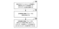
いくつかの例は、電気外科機器によって係合された生物組織に制御された電力を提供する方法に関する。この方法は、電気外科機器を介して生物組織に係合し、電気外科機器と係合された生物組織との間に電気通信を提供するステップを含む。この方法は、電気療法段階中、電気外科機器と電気的に通信する電気エネルギー源を介して、係合された生物組織に電気療法信号を提供するステップへ進む。この方法はまた、電気療法スケジュールに従って提供された電気療法信号の電力を制御するステップを含む。 Some examples relate to methods of providing controlled power to biological tissue engaged by an electrosurgical instrument. The method includes engaging biological tissue via an electrosurgical instrument and providing electrical communication between the electrosurgical instrument and the engaged biological tissue. The method proceeds with providing an electrotherapy signal to the engaged biological tissue during an electrotherapy phase via an electrical energy source in electrical communication with the electrosurgical instrument. The method also includes controlling the power of the provided electrotherapy signal according to the electrotherapy schedule.
装置および関連する方法は、電気外科機器によって係合された生物組織に電気療法信号を印加することに関する。これらの電気療法信号の様々な電気メトリックの制御が、そのような制御を実行する特有の電気外科技法として、以下に開示される。本明細書は、i)電気療法信号の電力制御(図1~図4)、ii)電気療法信号の予測段階制御(図5~図6)、iii)係合された生物組織の測定された電気抵抗の補正(図7A~図7Bおよび図9)、iv)初期インピーダンスの修正(図9)、v)電気療法信号の電力のパルス化による電気外科機器への生物組織の粘着の低減(図10A~図10Dおよび図11)、vi)電気外科機器によって係合された生物組織内の伝導性異物の有無の判定(図12および図13)、vii)トリガ値とエスケープ値との間のバンドによる短絡エラートラッピング(図14)、viii)インピーダンス限界終点波形に対する開回路確認(図15および図16)、ix)低精度ハードウェアシステムにおける代替電力補正出力(図17)、x)熱マージンが低減された複合エネルギーデバイス(図18および図19)、xi)低速CPUを有するシステムにおける熱マージンを制御するための段階的インピーダンス値(図20および図21)、xii)消費エネルギー監視および開回路評価(図22A~図22D)、xiii)パルス間のドエルタイム、ならびにxiv)監視される変数の関数としての制御パラメータの増分調整という名称の項目に構成される。これらの技法は、説明のみを目的として別個の項目に記載されている。逆の内容を明示的に記載しない限り、これらの技法の各々は、本開示に記載する他の技法のうちの1つ以上と組み合わせて使用することができる。 Apparatus and associated methods relate to applying electrotherapy signals to biological tissue engaged by an electrosurgical instrument. Various electrometric controls of these electrotherapy signals are disclosed below, as are specific electrosurgical techniques for performing such controls. The present specification describes i) power control of the electrotherapy signal (FIGS. 1-4), ii) predictive stepwise control of the electrotherapy signal (FIGS. 5-6), iii) the measured Correction of electrical resistance (FIGS. 7A-7B and 9); iv) modification of initial impedance (FIG. 9); 10A-10D and 11), vi) determining the presence or absence of a conductive foreign body in biological tissue engaged by an electrosurgical instrument (FIGS. 12 and 13), vii) band between trigger and escape values (Fig. 14), viii) open-circuit checking against impedance-limited endpoint waveforms (Figs. 15 and 16), ix) alternate power-corrected output in low-precision hardware systems (Fig. 17), x) reduced thermal margins multi-energy devices (FIGS. 18 and 19), xi) graded impedance values for controlling thermal margins in systems with slow CPUs (FIGS. 20 and 21), xii) energy consumption monitoring and open circuit evaluation ( 22A-22D), organized under the headings xiii) dwell time between pulses, and xiv) incremental adjustment of control parameters as a function of the monitored variable. These techniques are described in a separate section for illustrative purposes only. Each of these techniques can be used in combination with one or more of the other techniques described in this disclosure, unless expressly stated to the contrary.
電気療法信号の電力制御(図1~図4)
電気外科機器によって係合された生物組織の電気外科的な封止または凝固は、様々な医療処置で使用される電気外科技法である。係合された生物組織は、係合された生物組織を制御下で加熱することによって、電気外科的に封止することができる。いくつかの医療処置では、封止されている生物組織は血管である。血管を加熱することで、血管壁に見られるコラーゲンが変性する。この変性コラーゲンが、血管壁間の接着剤として作用するゲル状の物質を形成する。ともに押し付けられて冷却中にともに維持されると、血管の対向する壁が封止を形成する。Power control of electrotherapy signals (Figs. 1-4)
Electrosurgical sealing or coagulation of biological tissue engaged by an electrosurgical instrument is an electrosurgical technique used in a variety of medical procedures. The engaged biological tissue can be electrosurgically sealed by controlled heating of the engaged biological tissue. In some medical procedures, the biological tissue being sealed is a blood vessel. Heating the blood vessel denatures the collagen found in the blood vessel wall. This denatured collagen forms a gel-like substance that acts as an adhesive between the walls of blood vessels. When pressed together and held together during cooling, the opposing walls of the vessel form a seal.
血管の加熱は、血管へ提供されるエネルギーが少なすぎたり多すぎたりしないように、注意深く制御される。血管へ提供されるエネルギーが多すぎた場合、血管壁の炭化および/または焼損が生じる可能性がある。血管へ提供されるエネルギーが少なすぎた場合、血管の封止品質が不十分になる可能性がある。封止品質の1つの尺度は、封止された血管が破裂しないで耐えることができる差圧である。低品質の封止は、印加される圧力がある程度の値を超過すると損なわれる可能性がある。 Vessel heating is carefully controlled so that too little or too much energy is delivered to the vessel. If too much energy is provided to the vessel, charring and/or burning of the vessel wall can occur. If too little energy is provided to the vessel, the sealing quality of the vessel may be poor. One measure of sealing quality is the differential pressure that a sealed vessel can withstand without rupturing. A poor quality seal can be compromised if the applied pressure exceeds a certain value.
血管へエネルギーが提供される速度もまた、電気外科処置の急速な実施が容易になるように、注意深く制御することができる。電気外科処置の急速な実施は、これらの処置の時間および困難さを低減させる。しかし、加熱速度は、生物組織内の流体の無制御の沸騰を引き起こすほど急速に行うべきではない。無制御の沸騰は、係合された生物組織もしくは近隣の生物組織の破断、および/または封止の品質の低下を招く可能性がある。 The rate at which energy is provided to the vessel can also be carefully controlled to facilitate rapid performance of the electrosurgical procedure. Rapid performance of electrosurgical procedures reduces the time and difficulty of these procedures. However, the heating rate should not be so rapid as to cause uncontrolled boiling of the fluid within the biological tissue. Uncontrolled boiling can lead to rupture of the engaged or nearby biological tissue and/or loss of seal quality.
係合された生物組織の加熱は、係合された生物組織へ提供されて係合された生物組織によって放散される電気療法信号の電力を制御することによって制御することができる。そのような電力は、封止スケジュールに従って制御することができる。たとえば、封止スケジュールは、係合された生物組織の電圧差と係合された生物組織によって伝導される電流との積を示すことができる。したがって、封止スケジュールは電力スケジュールである。いくつかの例では、電気療法信号は、終了基準が満たされたことに応答して低減または終了させることができる。いくつかの例では、終了基準は、たとえば係合された生物組織によって伝導される電流の減少などの電流特性である。いくつかの例では、終了基準は、たとえば係合された生物組織の電気抵抗の増大などの抵抗特性である。電気抵抗が所定のデルタ抵抗値を超えるそのような増大は、たとえば終了基準として使用することができ、所定のデルタ抵抗値は、測定された抵抗(またはインピーダンス)とそのパルス内で測定された抵抗(またはインピーダンス)の最低値との間の差である。いくつかの例では、終了基準は、たとえば何らかの条件に基づいて事前決定または計算される持続時間などの時間条件である。 Heating of the engaged biological tissue can be controlled by controlling the power of the electrotherapy signal provided to and dissipated by the engaged biological tissue. Such power can be controlled according to a sealing schedule. For example, the sealing schedule can indicate the product of the voltage difference across the engaged biological tissue and the current conducted by the engaged biological tissue. A sealing schedule is therefore a power schedule. In some examples, the electrotherapy signal can be reduced or terminated in response to the termination criteria being met. In some examples, the termination criterion is a current characteristic, eg, a decrease in current conducted by the engaged biological tissue. In some examples, the termination criterion is a resistance characteristic, such as an increase in electrical resistance of the engaged biological tissue. Such an increase in electrical resistance over a given delta resistance value can be used, for example, as a termination criterion, where the given delta resistance value is the sum of the measured resistance (or impedance) and the measured resistance within that pulse. (or impedance) is the difference between the lowest values. In some examples, the termination criterion is a time condition, such as a duration that is predetermined or calculated based on some condition.
電気インピーダンスは複素インピーダンスであり、したがって実成分(抵抗)および虚数成分(リアクタンス)を含む。本明細書は、インピーダンスまたは抵抗を使用する技法について説明する。複素インピーダンス値も利用可能であり、そのような値を抵抗値の代わりに使用することもできることを理解されたい。逆に、複素インピーダンス値が利用可能でない場合、別途記載がない限り、抵抗値を代わりに使用することができる。 Electrical impedance is a complex impedance and thus contains a real component (resistance) and an imaginary component (reactance). This specification describes techniques that use impedance or resistance. It should be appreciated that complex impedance values are also available and such values can be used in place of resistance values. Conversely, if complex impedance values are not available, resistance values can be used instead, unless otherwise stated.
加えて、以下の技法の多くは、電気外科エネルギーを生物組織へ送達することについて説明する。逆の内容を示さない限り、これらの技法の各々は、電力制御式または電圧制御式の技法を使用して、電気外科エネルギーを送達することができる。電力制御式の実装では、制御回路は、たとえば計画またはスケジュールに従って、係合された生物組織に印加される電圧と電流との積を使用して、電気外科エネルギーの送達を制御することができる。たとえば、制御回路は、特定の段階、たとえば乾燥段階中に、一定の電力または単調に増大する電力の送達を制御することができる。 Additionally, many of the techniques below describe delivering electrosurgical energy to biological tissue. Unless indicated to the contrary, each of these techniques may use power-controlled or voltage-controlled techniques to deliver electrosurgical energy. In power-controlled implementations, the control circuit can control the delivery of electrosurgical energy using the product of voltage and current applied to the engaged biological tissue, for example according to a plan or schedule. For example, the control circuit can control the delivery of constant power or monotonically increasing power during a particular phase, such as a drying phase.
本明細書は、とりわけ治療または他の計画に従って提供することができる電気療法を提供するための1つ以上の技法について説明する。計画は、レシピ、処方、レジメン、方法論などを含むことができる。計画は、スケジュールなどの1つ以上の時間態様を含むことができ、たとえば発生または再発(または抑制もしくは抑止)タイミング、周波数、タイプ、相対的な組合せ(たとえば、切開と凝固)などを含むことができる。計画は、電気療法波形情報を含むことができ、たとえばパルス幅、デューティーサイクル、オン持続時間、オフ持続時間、繰返し率、振幅、段階などを含むことができる。計画は、本質的に静的または演繹的である必要はなく、1つ以上の動的態様を含むことができ、たとえば電気療法送達インスタンス中、またはそのような電気療法送達インスタンス間に、閉ループまたは他のフィードバックなどにおいて得られる診断情報、動作情報、または他の情報などによって、修正または決定することができる。計画の1つ以上の態様は、特有の患者、1つ以上の指定の特性を共有する人たちなどの患者の部分母集団、または患者の母集団などに合わせて調整することができ、たとえば記憶されている患者データに基づいて調整することができ、または患者もしくは介護人によって提供することができるものなどのユーザ入力によって調整することができる。計画は、1つ以上の条件態様を含むことができ、たとえば1つ以上の分岐条件を含むことができ、たとえば患者特性、診断方策、有効性判定、またはデバイスもしくはその環境の動作特性を使用して判定することができる。そのような分岐条件は、デバイスによって、たとえばユーザ入力を必要とすることなく、自動的に判定することができ、またはユーザ入力を必要とすることができ、たとえば電気療法デバイスの動作の1つ以上の部分の前、途中、もしくは後に、計画に従って提供することができる。計画は、入力、出力、もしくは命令、動作パラメータ、または測定データのうちの1つまたは任意の組合せを受信または提供するために、別のデバイスと通信すること、または別のデバイスを使用することを必要とすることができる。計画の1つ以上の態様は、コンピュータまたは他の機械可読媒体などの媒体に記録または符号化することができ、そのような媒体は、有形の媒体とすることができる。 This specification describes, among other things, one or more techniques for providing electrical therapy that may be provided in accordance with a therapeutic or other regimen. Plans can include recipes, formulas, regimens, methodologies, and the like. A plan can include one or more time aspects, such as a schedule, and can include, for example, onset or recurrence (or suppression or suppression) timing, frequency, type, relative combinations (e.g., incision and coagulation), and the like. can. The schedule can include electrotherapy waveform information, and can include, for example, pulse width, duty cycle, on duration, off duration, repetition rate, amplitude, phase, and the like. Planning need not be static or a priori in nature, but can include one or more dynamic aspects, such as closed-loop or Modifications or determinations may be made, such as by diagnostic information, operational information, or other information obtained, such as in other feedback. One or more aspects of the plan can be tailored to a particular patient, a subpopulation of patients such as those who share one or more specified characteristics, or a population of patients, for example, It can be adjusted based on patient data provided or can be adjusted by user input such as can be provided by the patient or caregiver. A plan can include one or more conditional aspects, such as one or more branching conditions, using, for example, patient characteristics, diagnostic strategies, efficacy determinations, or operating characteristics of the device or its environment. can be determined by Such branching conditions may be determined automatically by the device, e.g., without requiring user input, or may require user input, e.g. before, during, or after the portion of The plan is to communicate with or use another device to receive or provide one or any combination of input, output, or instructions, operating parameters, or measured data. can require. One or more aspects of the plan can be recorded or encoded on a medium, such as a computer or other machine-readable medium, and such medium can be a tangible medium.
電圧制御式の実装では、制御回路は、たとえば計画、レジメン、またはスケジュールに従って送達される電気外科エネルギーの電圧を制御することができる。たとえば、制御回路は、特定の段階、たとえば乾燥段階中に、一定の電圧または単調に増大する電圧の送達を制御することができる。 In voltage-controlled implementations, the control circuit can control the voltage of electrosurgical energy delivered according to, for example, a plan, regimen, or schedule. For example, the control circuit can control the delivery of a constant voltage or a monotonically increasing voltage during a particular phase, such as a drying phase.
図1は、外科患者の生物組織に電気療法を提供する電気外科システムの斜視図である。図1で、電気外科システム10は、電気外科ジェネレータ12および鉗子14を含み、鉗子14は、生物組織16に係合している状態で示されている。電気外科ジェネレータ12は、電気療法信号を生成しており、電気療法信号は、鉗子14を介して係合された生物組織16へ提供される。図1は、生物組織16に係合して生物組織16へ電気療法信号を送達する鉗子14を示しているが、そのような目的で、上記で開示したものなどの様々なタイプの電気外科機器を使用することができる。 1 is a perspective view of an electrosurgical system for providing electrotherapy to biological tissue of a surgical patient; FIG. In FIG. 1 ,
生物組織16へ電気療法信号を送達するために、様々なタイプの鉗子を同様に使用することができる。たとえば、鉗子14は、医療用鉗子、切開用鉗子、または電気外科用鉗子(たとえば、単極または双極鉗子)とすることができる。いくつかの例では、鉗子14は、血管、生物組織、静脈、動脈、または他の解剖学的特徴もしくは物体に操作、係合、把持、切開、焼灼、封止、または他の方法で影響を与えるために、開放および/または腹腔鏡医療処置などの医療関連処置に使用することができる。 Various types of forceps can similarly be used to deliver electrotherapy signals to
図1に示すように、鉗子14は、ハンドピース18、シャフトアセンブリ20、ナイフブレードアセンブリ22、および把持アセンブリ24を含む。図1に示す例など、いくつかの例では、鉗子14は、電気外科ジェネレータ12に電気的に接続されており、電気外科ジェネレータ12は、電気療法信号を生成し、生成した電気療法信号を鉗子14へ提供する。次いで、鉗子14は、その電気療法信号を、焼灼、封止、または他のそのような電気外科技法などの様々な電気外科技法に用いることができる把持アセンブリ24および/または遠隔パッドへ電気的に通信する。 As shown in FIG. 1 ,
ハンドピース18は、ハンドル26、把持レバー28、ナイフトリガ30、電気療法作動ボタン32、および回転ホイール34を含む。把持アセンブリ24は、第1の顎部材36および第2の顎部材38を含む。シャフトアセンブリ20は、近位端でハンドピース18に接続され、遠位端で把持アセンブリ24に接続される。シャフトアセンブリ20は、ハンドピース18から把持アセンブリ24へ長手方向40に遠位に延びる。
シャフトアセンブリ20は、鉗子14の一部分(たとえば、把持アセンブリ24およびシャフトアセンブリ20の遠位部分)を患者または他の解剖体に挿入しながら、鉗子14の残り部分(たとえば、ハンドピース18およびシャフトアセンブリ20の残りの近位部分)は患者または他の解剖体の外側に残すことを可能にするように機能する。シャフトアセンブリ20は、図1には実質的にまっすぐなものとして示されているが、他の例では、1つ以上の角度、曲げ、および/または円弧を含むことができる。シャフトアセンブリ20は、円形、長円形、もしくは他の断面プロファイルを有する円筒、またはハンドピース18から把持アセンブリ24まで延びる他の細長い部材とすることができる。いくつかの例では、シャフトは、曲げることができ、操縦でき、または他の形で撓ませることができるものとすることができる。
図1の例などのいくつかの例では、シャフトアセンブリ20は、ナイフブレードアセンブリ22を囲む細長い中空部材(たとえば、管状の外側シャフト)と、ナイフブレードアセンブリ22をナイフトリガ30に結合するための機械的リンク機構とを含むことができる。概して、シャフトアセンブリは、長手方向40に沿って力を伝達するのに十分な剛性を有する任意の細長い部材とすることができる。シャフトアセンブリ20はまた、ハンドピース18と把持アセンブリ24との間に電気通信を提供し、それによって電気療法信号を通信するために、伝導性要素(たとえば、ワイア、伝導性外側シャフト、および/または伝導性内側シャフトなど)を含むことができる。 In some examples, such as the example of FIG. 1, the
ハンドピース18の把持レバー28、ナイフトリガ30、電気療法作動ボタン32、および回転ホイール34は各々、通常は遠位端で、シャフトアセンブリ20の様々な作動を引き起こすように構成される。たとえば、把持レバー28の作動は、シャフトアセンブリ20の遠位端にある把持アセンブリ24の動作を制御するように構成される。把持レバー28は、開構成位置(図1に示す)と把持レバー28がハンドル26の方へ近位に動かされた閉構成位置との間で可動の把持アクチュエータである。把持レバー28をハンドル26の方へ閉構成位置まで近位に動かすことで、把持アセンブリ24が開構成から閉構成へ遷移する。把持レバー28を開構成位置へ遠位に動かすことで(たとえば、把持レバー28の解放)、把持アセンブリ24は閉構成から開構成へ遷移する。 Grasping
把持アセンブリ24の開構成と閉構成との間のそのような遷移は、第1の顎部材36および第2の顎部材38のうちの1つ以上が、第1の顎部材36および第2の顎部材38が隔置された開構成(図1に示す)と、第1の顎部材36と第2の顎部材38との間の間隙が低減または除去された閉構成との間で動くことによって実現される。様々な電気外科機器が、様々な方法で生物組織16に係合する。図1に示すものなどのいくつかの電気外科機器では、第1の顎部材36および第2の顎部材38は、互いに対置可能である。図示の例では、第1の顎部材36および第2の顎部材38は、第1の顎部材36と第2の顎部材38との間に生物組織16を締め付けて、締め付けられた生物組織16を介して対置可能な顎部材36および38間に電気通信を提供するように構成される。他の電気外科機器が、他の方法で生物組織に係合することもできる。 Such a transition between the open configuration and the closed configuration of gripping
シャフトアセンブリ20内の機械的リンク機構は、把持レバー28の作動に応答して、第1の顎部材36および第2の顎部材38のうちの1つ以上を開構成と閉構成との間で動かすように構成することができる。把持アセンブリを開構成と閉構成との間で動かすための1つの例示的な機構は、内容全体を本願に引用して援用する、2017年1月10日出願のバチェラー(Batchelor)らによる「FORCEPS JAW MECHANISM」という名称の米国特許公開第2017/0196579号に見ることができる。 A mechanical linkage within
ナイフトリガ30の作動は、シャフトアセンブリ20の遠位端に位置するナイフブレードアセンブリ22の動作を制御するように構成される。ナイフブレードアセンブリ22は、第1の顎部材36と第2の顎部材38との間に締め付けられた生物組織または他の物体に切開、切除、または他の方法で影響を与えるように構成される。ナイフトリガ30は、後退構成位置(図1に示す)と配備または延長構成位置との間で可動のナイフブレードアクチュエータであり、配備構成位置では、ナイフトリガ30がハンドル26の方へ近位に動かされて、ナイフブレードアセンブリ22が、第1の顎部材36と第2の顎部材38との間に締め付けられた生物組織16を切開する。ナイフトリガ30をハンドル26の方へ配備構成位置まで近位に動かすことで、ナイフブレードアセンブリ22の刃が生物組織16に係合し、それによって生物組織16を切開する。ナイフトリガ30を遠位に動かすことで(たとえば、ナイフトリガ30の解放)、ナイフブレードは締め付けられた生物組織16から後退する。たとえばシャフトアセンブリ20内の機械的リンク機構は、ナイフブレードを生物組織16に係合させ、係合された生物組織16から後退させるように構成することができる。 Actuation of
回転ホイール34は、シャフトアセンブリ20の遠位端にあるナイフブレードアセンブリ22および把持アセンブリ24のうちの1つ以上の回転構成、ならびに/またはシャフトアセンブリ20の回転構成を制御するように構成される。回転ホイール34の動き(たとえば、回転)は、長手方向40に延びる軸の周りで、シャフトアセンブリ20、ナイフブレードアセンブリ22、および把持アセンブリ24のうちの1つ以上を回転させる。そのような回転制御は、把持アセンブリおよび/またはナイフブレードアセンブリを、締め付けられた生物組織16に位置合わせすることを容易にすることができる。
療法作動ボタン32は、電気療法信号の生成および/または係合された生物組織16への送達を制御するように構成される。療法作動ボタン32を作動することで、たとえば電気外科ジェネレータ12から引き込まれた電気療法信号を、第1の顎部材36および第2の顎部材38、遠隔パッド(図示せず)、または鉗子14の他の部分のうちの1つ以上に印加して、患者または他の解剖体に焼灼、封止、または他の方法で電気的に影響を与える。把持レバー、ナイフトリガ、回転ホイール、および療法作動ボタンを利用するハンドピースの一例は、内容全体を本願に引用して援用する、2017年6月20日に発行されたウィンドガッセン(Windgassen)らによる「FORCEPS WITH A ROTATION ASSEMBLY」という名称の米国特許第9,681,883号に見ることができる。
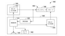
図2は、電気外科機器によって係合された生物組織を封止する電気外科システムのブロック図である。図2で、電気外科システム10は、電気外科ジェネレータ12および電気外科機器14’を含む。電気外科機器14’は、生物組織に係合して生物組織に電気療法信号を送達するように構成された任意の電気外科機器とすることができる。電気外科ジェネレータ12は、高周波(AC)電気信号などの電気療法信号を生成するように構成され、電気外科機器14’は、その電気信号を、係合された生物組織16へ送達する。 FIG. 2 is a block diagram of an electrosurgical system for sealing biological tissue engaged by an electrosurgical instrument; In FIG. 2,
いくつかの例では、電気外科機器14’は、図1に示す鉗子14など、シャフトアセンブリを介して対置可能な顎部材に結合されたハンドピースを有する鉗子である。他の例では、電気外科機器14’は、伝導性スパチュラ、伝導性パッド、または他の電気外科デバイスである。これらの様々なタイプの電気外科機器は、生物組織に係合する様々な方法(たとえば、締め付ける、触れる、取り囲む、貫入する、放射するなど)を有する。 In some examples, electrosurgical instrument 14' is a forceps having a handpiece coupled to apposable jaw members via a shaft assembly, such as
電気外科ジェネレータ12は、機器インターフェース42、電気エネルギー源44、測定回路46、制御回路48、およびユーザインターフェース50を含む。機器インターフェース42は、たとえば信号ドライバ、バッファ、増幅器、ESD保護デバイス、および電気コネクタ52を含むことができる。電気コネクタ52は、電気外科機器14’を電気外科ジェネレータ12に電気的に結合して、電気外科ジェネレータ12と電気外科機器14’との間に電気通信を提供するように構成される。そのような電気通信を使用して、電気外科ジェネレータ12と電気外科機器14’との間で動作電力および/または電気信号を伝送することができる。それによって、電気外科機器14’は、電気コネクタ52と係合された生物組織との間に電気通信を提供することができる。
電気エネルギー源44は、電気的に接続された電気外科機器14’を介して係合された生物組織へ送達される電気療法信号を生成するように構成される。生成された電気療法信号は、特有の電気外科処置に対する所望の結果が得られるように制御することができる。一例では、たとえば、電気療法信号は、係合された生物組織を抵抗加熱して、係合された生物組織を封止するなど、係合された生物組織に外科的に影響を与えるように構成される。電気療法信号のそのような制御は、以下でさらに開示する。
測定回路46は、接続された電気外科機器14’によって係合された生物組織の1つ以上の電気パラメータを測定するように構成される。測定回路46は、電気外科ジェネレータ12が電気コネクタ52を介して電気外科機器14’に電気的に接続されたとき、接続された電気外科機器14’と電気的に通信する。測定回路46の様々な例は、様々な電気パラメータを測定するように構成される。たとえば、測定回路46は、係合された生物組織に送達される電圧差および/または係合された生物組織によって伝導される電流を測定するように構成することができる。いくつかの例では、測定回路46は、係合された生物組織に送達される電圧差と係合された生物組織によって伝導される電流との間の位相角を測定するように構成することができる。いくつかの例では、測定回路46は、係合された生物組織のDCおよび/またはAC電気パラメータを測定するように構成される。
係合された生物組織に送達される電圧差および/または係合された生物組織によって伝導される電流などの測定されたパラメータは、他の電気メトリックを判定するために使用することもできる。たとえば、係合された生物組織に送達される電圧差および/または係合された生物組織によって伝導される電流の測定を使用して、係合された生物組織の電気抵抗を判定することができる。係合された生物組織に送達される電圧差および係合された生物組織によって伝導される電流、ならびにこれらの間の位相角の測定を使用して、係合された生物組織の複素インピーダンスを判定することができる。また、係合された生物組織に送達される電圧差および係合された生物組織によって伝導される電流、ならびにこれらの間の位相角の測定を使用して、係合された生物組織へ提供される皮相電力(VA)および/または有効電力(W)を判定することもできる。 Measured parameters such as the voltage difference delivered to the engaged biological tissue and/or the current conducted by the engaged biological tissue can also be used to determine other electrical metrics. For example, measuring the voltage difference delivered to the engaged biological tissue and/or the current conducted by the engaged biological tissue can be used to determine the electrical resistance of the engaged biological tissue. . Measuring the voltage difference delivered to the engaged biological tissue and the current conducted by the engaged biological tissue, and the phase angle therebetween, is used to determine the complex impedance of the engaged biological tissue. can do. Also, using a measurement of the voltage difference delivered to the engaged biological tissue and the current conducted by the engaged biological tissue, and the phase angle therebetween, the Apparent power (VA) and/or real power (W) can also be determined.
電気パラメータのそのような測定は、係合された生物組織への送達中に電気療法信号を制御するために使用することができる。たとえば、係合された生物組織に送達される電圧差の測定および係合された生物組織によって伝導される電流の測定を使用して、係合された組織へ提供される有効電力を判定および/または制御することができる。次いで、こうして判定された有効電力と、電気療法スケジュールとを比較することができる。そのような比較を使用して、エラー信号を生成することができる。電気パラメータの測定はまた、電気療法の段階を制御するための段階制御基準を判定するために使用することができる。段階制御基準は、段階の開始および終了のための基準、ならびに段階内制御のための基準を含むことができる。 Such measurements of electrical parameters can be used to control electrotherapy signals during delivery to engaged biological tissue. For example, measuring the voltage difference delivered to the engaged biological tissue and measuring the current conducted by the engaged biological tissue are used to determine the effective power provided to the engaged tissue and/or or can be controlled. The active power thus determined can then be compared to the electrotherapy schedule. Such comparisons can be used to generate error signals. Electrical parameter measurements can also be used to determine phase control criteria for controlling phases of electrotherapy. Phase control criteria can include criteria for phase initiation and termination, as well as for intra-phase control.
制御回路48は、電気エネルギー源44および/または測定回路46の動作を制御するように構成される。制御回路48は、電気エネルギー源44および測定回路46に電気的に接続される。制御回路48は、電気エネルギー源に、電気的に接続された電気外科機器14’によって係合された生物組織へ電気療法信号を提供させる。制御回路48は、電気エネルギー源44に、電気療法スケジュールに従って電気療法信号を生成させ、生成された電気療法信号は、特有の電気外科処置に合わせて制御される。
様々な電気療法スケジュールは、様々なタイプの電気療法を実現するために使用することができる。たとえば、いくつかの例では、係合された生物組織へ提供される電気療法信号の有効電力(W)は、電力スケジュールに従って制御される。他の例では、係合された生物組織に送達される電気療法信号の電圧差(V)は、電圧スケジュールに従って制御される。他の例では、係合された生物組織によって伝導される電気療法信号の電流(A)は、電流スケジュールに従って制御される。さらに他の例では、係合された生物組織へ提供される電気療法信号の皮相電力(VA)を、電圧-アンペア数スケジュールに従って制御することができる。 Different electrotherapy schedules can be used to deliver different types of electrotherapy. For example, in some instances the effective power (W) of the electrotherapy signal provided to the engaged biological tissue is controlled according to a power schedule. In another example, the voltage difference (V) of the electrotherapy signal delivered to the engaged biological tissue is controlled according to a voltage schedule. In another example, the electrical current (A) of the electrotherapy signal conducted by the engaged biological tissue is controlled according to a current schedule. In yet another example, the apparent power (VA) of an electrotherapy signal provided to engaged biological tissue can be controlled according to a voltage-amperage schedule.
たとえば、制御回路48は、電気エネルギー源44に、係合された生物組織へエネルギーを提供させることができ、係合された生物組織の電圧差と係合された生物組織によって伝導される電流との積が、電気療法スケジュールに従って制御される。制御回路48は、判定された有効電力と電気療法スケジュールとの比較を使用して、エラー信号を生成することができる。そのようなエラー信号は、電気エネルギー源44を含む閉ループフィードバックシステムにおいて、電気療法スケジュールに従って電気療法信号を生成するために使用することができる。 For example, the
図2に示すように、制御回路48は、プロセッサ54およびメモリ56を含む。制御回路48は、タイマおよび/またはクロックを含むことができる。いくつかの例では、タイマおよび/またはクロックは、プロセッサ54の一部である。他の例では、タイマおよび/またはクロックは、プロセッサ54とは別個である。一例では、プロセッサ54は、電気外科システム10内での実行のために、機能の実施および/または命令の処理を行うように構成される。たとえば、プロセッサ54は、プログラムメモリ56P内に記憶されている命令を受信および/または処理することが可能である。次いで、プロセッサ54は、電気エネルギー源44に所定の電気療法スケジュールに従って電気療法信号を生成させるためのプログラム命令を実行することができる。所定の電気療法スケジュールは、たとえばデータメモリ56Dから取り出すことができる。プロセッサ54は、測定回路46によって測定された電気パラメータと、取り出された所定の電気療法スケジュールとを比較することができる。プロセッサ54は、電気エネルギー源44および/または測定回路46へコマンドを送信することができる。プロセッサ54はまた、ユーザインターフェース50からの情報を送信または受信することができる。 As shown in FIG. 2,
様々な例では、電気外科ジェネレータ12は、図2に示す要素または様々な他の要素を使用して実現することができる。たとえば、プロセッサ54は、マイクロプロセッサ、制御回路、デジタル信号プロセッサ(DSP)、特定用途向け集積回路(ASIC)、フィールドプログラマブルゲートアレイ(FPGA)、または他の同等の離散もしくは集積論理回路のうちのいずれか1つ以上を含むことができる。 In various examples,
メモリ56は、動作中に電気外科システム10内に情報を記憶するように構成することができる。いくつかの例では、メモリ56について、コンピュータ可読記憶媒体として説明する。いくつかの例では、コンピュータ可読記憶媒体は、非一時的な媒体を含むことができる。「非一時的」という用語は、記憶媒体がキャリア波または伝播信号として実施されたものではないことを示すことができる。特定の例では、非一時的記憶媒体は、経時変化しうるデータを記憶することができる(たとえば、RAMまたはキャッシュ内)。いくつかの例では、メモリ56は、一時的なメモリであり、これはメモリ56の主目的が長期記憶ではないことを意味する。いくつかの例では、メモリ56について、揮発性メモリとして説明しており、これは、電気外科システム10への電力が遮断されたときに、メモリ56が記憶された内容を維持しないことを意味する。揮発性メモリの例は、ランダムアクセスメモリ(RAM)、ダイナミックランダムアクセスメモリ(DRAM)、スタティックランダムアクセスメモリ(SRAM)、および他の形態の揮発性メモリを含むことができる。いくつかの例では、メモリ56は、プロセッサ54による実行のためのプログラム命令を記憶するために使用される。一例では、メモリ56は、電気外科システム10で動作するソフトウェアまたはアプリケーション(たとえば、電気外科機器によって係合された生物組織へ提供される電気療法信号の電気制御を実施するソフトウェアプログラム)によって、プログラム実行中にたとえばデータメモリ56D内などに情報を一時的に記憶するために使用される。
いくつかの例では、メモリ56はまた、1つ以上のコンピュータ可読記憶媒体を含むことができる。メモリ56は、揮発性メモリより大量の情報を記憶するように構成することができる。メモリ56は、情報の長期記憶向けにさらに構成することができる。いくつかの例では、メモリ56は、不揮発性記憶要素を含む。そのような不揮発性記憶要素の例は、磁気ハードディスク、光ディスク、フラッシュメモリ、または電気的プログラマブルメモリ(EPROM)もしくは電気的に消去可能なプログラマブルメモリ(EEPROM)の形態を含むことができる。 In some examples,
ユーザインターフェース50は、電気外科システム10とユーザ(たとえば、外科医または技術者)との間で情報を通信するために使用することができる。ユーザインターフェース50は、通信モジュールを含むことができる。ユーザインターフェース50は、様々なユーザ入出力デバイスを含むことができる。たとえば、ユーザインターフェースは、様々なディスプレイ、可聴信号ジェネレータ、ならびにスイッチ、ボタン、タッチスクリーン、マウス、キーボードなどを含むことができる。
一例では、ユーザインターフェース50は、通信モジュールを利用して、1つ以上の無線もしくは有線ネットワークまたはその両方などの1つ以上のネットワークを介して外部デバイスと通信する。通信モジュールは、イーサネットカードなどのネットワークインターフェースカード、光トランシーバ、無線周波トランシーバ、または情報を送信および受信することができる任意の他のタイプのデバイスを含むことができる。そのようなネットワークインターフェースの他の例は、Bluetooth(登録商標)、3G、4G、およびWi-Fi無線コンピューティングデバイス、ならびにユニバーサルシリアルバス(USB)デバイスを含むことができる。 In one example,
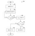
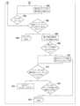
図3A~図3Bは、電気外科機器によって係合された生物組織を封止するための電気療法信号を生成する方法の非限定的な例の流れ図である。図3A~図3Bに示す方法100は、図1~図2に示す電気外科システム10などの電気外科システムとともに使用することができる。後述する様々な技法を使用して、電気外科ジェネレータは、生物組織の測定された電気パラメータの変化の関数としてのエネルギー送達の増分変化に従って、療法段階の一部分中に生物組織へ提供される療法信号のエネルギー送達を制御することができる。いくつかの例では、制御回路は、組織修正を提供する段階中に電力を制御することなどによって、療法計画に従って、療法段階の一部分中に生物組織へ提供される療法信号の電力を制御することができる。 3A-3B are flow diagrams of non-limiting examples of methods for generating electrotherapy signals for sealing biological tissue engaged by an electrosurgical instrument. The
たとえば、制御回路は、電流の関数として電力を増分的に修正することができる。いくつかの例では、電流の関数は、電流の変化の関数である。電流の変化は、パルス中の電流の変化とすることができ、したがってむしろ電流値のように見える可能性がある。いくつかの例では、電流の関数は、測定された電流の瞬時変化の関数であり、したがってむしろ電流関数の勾配のように見える可能性がある。制御回路は、これらの電流の変化または電流の瞬時変化のいずれかに基づいて、電力を修正することができる。いくつかの例では、測定された電流の瞬時変化の関数は、線形関数である。他の例では、制御回路は、電圧制御式の技法を使用するときなどに、抵抗の関数として電力を増分的に修正することができる。 For example, the control circuit can incrementally modify power as a function of current. In some examples, the function of current is a function of change in current. A change in current may be a change in current during a pulse, and thus may look more like a current value. In some examples, the function of current may be a function of the instantaneous change in measured current and thus look more like the slope of the current function. The control circuit can modify the power based on either these current changes or instantaneous changes in current. In some examples, the function of instantaneous change in measured current is a linear function. In other examples, the control circuit can incrementally modify the power as a function of resistance, such as when using voltage controlled techniques.
図4に見られるように、いくつかの例では、システムは、事前定義された電力曲線を使用して、療法段階の一部分中に生物組織へ提供される療法信号の電力を制御することができる。いくつかの例では、事前定義された電力曲線は、2つ以上の線形部分を含むことができる。 As seen in FIG. 4, in some examples, the system can use a predefined power curve to control the power of the therapy signal provided to the biological tissue during a portion of the therapy phase. . In some examples, a predefined power curve can include more than one linear portion.
図3Aおよび図3Bならびに図4は、説明の目的で使用される非限定的な特有の例であることに留意されたい。 Note that FIGS. 3A and 3B and FIG. 4 are non-limiting specific examples used for illustrative purposes.
いくつかの例では、この方法は、電力制御式の技法の使用から電圧制御式の技法の使用へ切り換えることができる。電圧制御式の技法では、電流の上限を定めることができるが、電流は、応答インピーダンスに従って自由に動くことが可能であり、それにより可変電力送達を可能にすることができる。たとえば、制御回路は、電力制御式の技法を使用してパルスを送達することができ、抵抗が増大すると、沸騰条件に接近し、または閾値に到達し、システムは、電圧制御式の技法に切り換わることができる。このようにして、初めに、システムは、電力制御式の技法を利用して、エネルギーをより速く送達することができるが、沸騰に近づくと、システムは、より応答が速い電圧制御式の技法に切り換わることができる。電圧制御式の技法を使用するいくつかの実装では、システムは、事前定義された電圧曲線を使用して、療法段階の一部分中に生物組織へ提供される療法信号の電力を制御することができる。いくつかの例では、事前定義された電圧曲線は、2つ以上の線形部分を含むことができる。 In some examples, the method can switch from using a power-controlled technique to using a voltage-controlled technique. In voltage-controlled techniques, the current can be capped, but the current can be free to move according to the response impedance, thereby allowing variable power delivery. For example, the control circuit may deliver the pulse using a power-controlled technique, and as the resistance increases, a boiling condition is approached or a threshold is reached, the system switches to a voltage-controlled technique. can be replaced. In this way, initially, the system can utilize a power-controlled technique to deliver energy faster, but near boiling, the system transitions to a more responsive voltage-controlled technique. can switch. In some implementations using voltage-controlled techniques, the system can use a predefined voltage curve to control the power of the therapy signal delivered to the biological tissue during a portion of the therapy phase. . In some examples, a predefined voltage curve can include more than one linear portion.
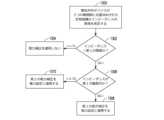
図3Aで、方法100はステップ102から始まり、電気外科システム10(図1~図2に示す)に電力が投入される。次いで、ステップ104で、呼掛け段階が始まり、制御回路48(図2に示す)が、電気エネルギー源44(図2に示す)に、呼掛け段階中に、係合された生物組織へ呼掛けパルスなどの呼掛け信号を提供させる。提供された呼掛け信号の電力(W)は、呼掛けスケジュールに従って制御される。いくつかの例では、呼掛け段階中に係合された生物組織へ提供される電力レベルは、組織作用をほとんどまたはまったく引き起こさないほど低くすることができる。そのような低い電力レベルは、係合された生物組織の電気特性の測定値を得る目的で提供することができる。そのような測定値は、場合により、電気療法前測定値を得るために、電気療法が提供される前に得られる。いくつかの例では、呼掛けスケジュールは、呼掛け段階中に一定の電力を提供することを示す。そのようなスケジュールを、一定電力スケジュールと呼ぶことができる。いくつかの例では、制御回路48は、所定の持続時間後に呼掛け段階を終了させる。 In FIG. 3A,
ステップ106で、コントローラ48は、測定回路46(図2に示す)に、呼掛け段階中に、係合された生物組織の第1の電気抵抗を測定させる。ステップ106が初めて実行されるとき、この測定された電気抵抗が基準抵抗になる。次いで、ステップ108で、制御回路48は、測定された電気抵抗と、以前に測定された最小の抵抗(もしあれば)とを比較する。ステップ108で、測定された電気抵抗が最小の抵抗より小さい場合、この方法はステップ110へ進み、測定された電気抵抗が、新しい最小値として記録され、次いでこの方法はステップ116へ進む(乾燥または脱水段階の第1の区間が始まる)。しかし、ステップ108で、測定された電気抵抗が最小の抵抗より大きい場合、この方法はステップ112へ進み、制御回路48は、測定された電気抵抗と、最小の抵抗および所定の抵抗デルタの和とを比較する。ステップ112で、測定された電気抵抗が、最小の抵抗および所定の抵抗デルタの和より小さい場合、この方法はステップ114へ進み、測定された電気抵抗は無視される。しかし、ステップ112で、測定された電気抵抗が、最小の抵抗および所定の抵抗デルタの和より大きい場合、この方法は、図3Bに示すステップ146へ進む。 At
ステップ116で、組織修正が行われるなど、乾燥または脱水段階の第1の区間が始まり、制御回路48は、電気エネルギー源44に、乾燥段階の第1の乾燥区間中に、係合された生物組織へ第1の乾燥パルスなどの第1の乾燥信号を提供させる。提供された第1の乾燥信号の電力(W)は、線形傾斜率を有するなど、事前定義された電力曲線などを使用して、第1の乾燥スケジュールまたは計画に従って制御される。いくつかの例では、第1の乾燥スケジュールまたは計画は、図4の下のグラフで時間t1およびt2間に示すように、単調に増大する電力スケジュールである。At
次いで、ステップ118で、制御回路48は、提供された電力と、第1の所定の最大電力などの第1の閾値とを比較する。ステップ118で、提供された電力が第1の所定の最大電力より大きい場合、この方法は、図4の下のグラフで時間t2およびt3間に示すように、図3Bに示すステップ130へ進み、これは乾燥段階の第2の乾燥区間を示す。第2の乾燥区間を含むいくつかの例では、制御回路48は、ブロック130で、図4の下のグラフで時間t2およびt3間に示すように、傾斜率を低減させることができる。このようにして、制御回路48は、係合された生物組織のたとえば断続的に測定された第1の電気パラメータが第1の閾値を満たすことに応答して、第1の乾燥パルスなどの第1のパルス中に、エネルギー送達を修正することができる。
システムは、電流などの第1の電気パラメータを、たとえば断続的に測定することができ、係合された生物組織の測定された電流が所定の値などの第1の閾値を満たすことに応答して、療法段階中にエネルギー送達を低減または終了させる。いくつかの例では、所定の値は、絶対電流閾値である。いくつかの例では、所定の値は、パルス計数に応じて変化することができる閾値である。いくつかの例では、所定の値は、初期電流測定値に対する電流の変化である。いくつかの例では、所定の値は、療法信号のパルス中の最大電流測定値に対する電流の変化である。 The system can measure a first electrical parameter, such as current, for example intermittently, and responds that the measured current of the engaged biological tissue meets a first threshold, such as a predetermined value. to reduce or terminate energy delivery during the therapy phase. In some examples, the predetermined value is an absolute current threshold. In some examples, the predetermined value is a threshold that can change depending on the pulse count. In some examples, the predetermined value is the change in current relative to the initial current measurement. In some examples, the predetermined value is the change in current relative to the maximum current measurement during the pulse of the therapy signal.
しかし、ステップ118で、提供された電力が第1の所定の最大電力より小さい場合、この方法はステップ120へ進み、制御回路48は、測定回路46に、係合された生物組織によって伝導されるインピーダンスまたは電流などの第1の電気パラメータを測定させる。 However, if at
ステップ122で、制御回路48は、このパルスに対する測定された電流(またはインピーダンス)、たとえば第1の電気パラメータと、以前に測定された最大電流(もしあれば)、たとえば閾値とを比較する。ステップ122で、測定された電流が最大電流より大きい場合、この方法はステップ124へ進み、測定された電流は、新しい最大値として記録され、次いでこの方法はステップ116へ戻り、第1のパルス中のエネルギー送達を修正することによって、乾燥段階の第1の乾燥区間を継続する。しかし、ステップ122で、測定された電流が最大電流より小さい場合、この方法はステップ126へ進み、制御回路48は、測定された電流と、最大電流の所定の割合とを比較する。 At
ステップ126で、測定された電流、たとえば測定された第1の電流が、所定の電流閾値、たとえば測定された第2の電流より大きい場合、この方法はステップ116へ戻り、乾燥段階の第1の乾燥区間を継続する。いくつかの例では、所定の電流閾値は、たとえば0.9、0.8、0.66、0.5、および0.4など、最大電流の比または割合とすることができる。言い換えれば、制御回路48は、測定された第1の電流と測定された第2の電流との比が、係合された生物組織内の液体の相変化が生じていないことを示す所定の係数を超過したことに応答して、乾燥信号またはパルスを継続することができる。他の例では、所定の電流閾値を比ではなく差とすることができる。 At
しかし、ステップ126で、測定された電流が最大電流の所定の割合より小さい場合、この方法はステップ128へ進み、乾燥段階の第1の乾燥区間の第1の乾燥パルスが終了される。次いで、この方法はステップ104へ戻り、呼掛け段階を繰り返し、その後、乾燥段階を繰り返すことができ、または封止段階が始まることができる。言い換えれば、システムは、療法段階中に電流を監視して、その療法段階がいつ終了するべきかを判定することができる。 However, if at
いくつかの例では、ステップ126で、測定された電流が最大電流の所定の割合より小さいかどうかを判定することとは対照的に、制御回路48は、測定された電流が、パルスの始動後に所定の時間間隔で測定された電流値の所定の割合(またはオフセット)より小さいかどうかを判定することができる。インピーダンス監視システムの場合、制御回路48は、測定されたインピーダンスが、パルスの始動後に所定の時間間隔で測定された抵抗値の所定の割合(またはオフセット)より大きいかどうかを判定することができる。 In some examples, as opposed to determining at
ステップ130(図3Bに示す)で、乾燥段階の第2の区間が始まり、制御回路48は、電気エネルギー源44に、乾燥段階の第2の乾燥区間中に、係合された生物組織へ第2の乾燥パルスなどの第2の乾燥信号を提供させる。乾燥段階の第1および第2の乾燥区間を図3Aおよび図3Bに示すが、乾燥段階の第2の乾燥区間はなくてもよいことに留意されたい。逆に、いくつかの例では、乾燥段階が第1の乾燥区間中に終了することができる。第2の乾燥パルスなどの提供された第2の乾燥信号の電力(W)は、事前定義された電力曲線などを使用して、第2の乾燥スケジュールまたは計画に従って制御される。電力制御式(または電圧制御式もしくは電流制御式)の技法では、システムは、作動エネルギーレベルの設定を制御することができる。電力(または電圧もしくは電流)の制約は、制御される電流が交差しない上限または閾値を指し、これを超えるとエラー状態が生じる。 At step 130 (shown in FIG. 3B), the second leg of the drying phase begins,
他の例では、係合された生物組織の電圧(V)は、第2の乾燥区間中に制御される。電圧制御式の技法では、システムは、作動エネルギーレベルの設定を制御することができる。電圧の制約は、制御される電圧が交差しない上限または閾値を指し、これを超えるとエラー状態が生じる。電圧制御式の実装では、制御回路は、療法信号の電圧を監視することができ、閾値または上限が満たされたとき、制御回路は、電圧をその閾値で維持することができる。いくつかの電圧制御式の実装では、電圧は上限で制限することができる。他の電圧制御式の実装では、電圧は、時間で変化することができる。 In another example, the voltage (V) of the engaged biological tissue is controlled during the second drying interval. Voltage-controlled techniques allow the system to control the setting of the actuation energy level. A voltage constraint refers to an upper limit or threshold that the controlled voltage will not cross, beyond which an error condition will occur. In voltage-controlled implementations, the control circuit can monitor the voltage of the therapy signal, and when a threshold or upper limit is met, the control circuit can maintain the voltage at that threshold. In some voltage controlled implementations, the voltage can be capped at an upper limit. In other voltage-controlled implementations, the voltage can vary with time.
図示の例では、第2の乾燥区間は、単調に増大する電力スケジュールである第2の乾燥スケジュールまたは計画を使用する。いくつかの例では、たとえば、第2の乾燥スケジュールまたは計画は、線形に増大する電力スケジュールである。次いで、ステップ132で、制御回路48は、提供された電力と第2の所定の最大電力とを比較する。ステップ132で、提供された電力が第2の所定の最大電力より大きい場合、この方法はステップ134へ進み、制御回路48は、電気エネルギー源44に、第2の所定の最大電力、たとえば電力上限に等しい電力を提供させ、次いで方法100はステップ136へ進む。しかし、ステップ132で、提供された電力が第2の所定の最大電力より小さい場合、この方法はステップ136へ進み、制御回路48は、測定回路46に、係合された生物組織によって伝導される電流を測定させる。 In the illustrated example, the second drying leg uses a second drying schedule or scheme that is a monotonically increasing power schedule. In some examples, for example, the second drying schedule or plan is a linearly increasing power schedule. At
ステップ138で、制御回路48は、測定された電流と以前に測定された最大電流とを比較する。ステップ138で、測定された電流が最大電流より大きい場合、この方法はステップ140へ進み、測定された電流は、新しい最大値として記録され、次いでこの方法はステップ130へ戻り、第2の乾燥段階を継続する。しかし、ステップ138で、測定された電流が最大電流より小さい場合、この方法はステップ142へ進み、制御回路48は、測定された電流と最大電流の所定の割合とを比較する。ステップ142で、測定された電流が最大電流の所定の比または割合より大きい場合、この方法はステップ130へ戻り、乾燥段階の第2の乾燥区間を継続する。言い換えれば、制御回路48は、測定された第1の電流と測定された第2の電流との比が、係合された生物組織内の液体の相変化を示す所定の係数を超過したことに応答して、乾燥信号またはパルスを低減させることができる。他の例では、所定の電流閾値を差とすることができる。しかし、ステップ142で、測定された電流が最大電流の所定の割合より小さい場合、この方法は、乾燥段階の第2の区間を出て、ステップ104へ戻り、呼掛け段階を繰り返すことができ、その後、乾燥段階を繰り返すことができ、または封止段階が始まることができる。言い換えれば、システムは、療法段階中に電流を監視して、その療法段階がいつ終了するべきかを判定することができる。 At
ステップ146で、封止または凝固段階が始まり、制御回路48は、電気エネルギー源44に、図4の下のグラフで時間t7およびt8間に示すように、封止段階中に、係合された生物組織へ封止パルス、たとえば第2のパルスなどの封止信号を提供させる。封止パルスなどの提供された封止信号の電力(W)は、封止スケジュールまたは計画に従って制御される。いくつかの例では、封止スケジュールまたは計画は、単調に増大する電力スケジュールである。次いで、ステップ148で、制御回路48は、提供された電力と第3の所定の最大電力とを比較する。これは所定の電力曲線の一例であり、偶然に一定の電力ドメインを有することに留意されたい。ステップ148で、提供された電力が第3の所定の最大電力より大きい場合、この方法はステップ150へ進み、制御回路48は、電気エネルギー源44に、第3の所定の最大電力に等しい電力を提供させ、次いで方法100はステップ152へ進み、組織の抵抗など、係合された生物組織の第2のパラメータを、たとえば断続的に測定する。しかし、ステップ148で、提供された電力が第3の所定の最大電力より小さい場合、この方法はステップ152へ進み、制御回路48は、測定回路46に、係合された生物組織の電気抵抗を測定させる。At
ステップ154で、制御回路48は、測定された電気抵抗と、計算された終了抵抗値などの第2の閾値とを比較する。いくつかの例では、計算された終了抵抗値の抵抗は、ステップ106で測定された基準抵抗、たとえば第1の抵抗に基づいて計算される。たとえば、終了抵抗値は、所定の係数に測定された基準抵抗を掛けた値とすることができる。いくつかの例では、終了抵抗値は、所定の抵抗デルタと、測定された基準抵抗、またはその段階もしくは以前の段階中に測定された抵抗の最小値のいずれかとの和とすることができる。いくつかの例では、標的抵抗は、所定のデルタ抵抗であり、所定のデルタ抵抗は、療法信号のパルス中の最小の抵抗測定値に対する抵抗の変化である。 At
ステップ154で、測定された電気抵抗が計算された終了抵抗より小さい場合、この方法はステップ146へ戻り、封止段階を継続する。しかし、ステップ154で、測定された電気抵抗が計算された終了抵抗より大きい場合、封止段階が終了され、この方法は終了する。言い換えれば、たとえば断続的に測定されたインピーダンスが、たとえば所定のデルタインピーダンス値だけ変化するなど、第2の閾値を満たすことに応答して、この方法は、封止段階などのこの療法段階中にエネルギー送達を低減または終了させることなどによって、第2のパルスのエネルギー送達を修正することができる。 At
いくつかの非限定的な例では、図3Aおよび図3Bに示す方法は、制御回路が、乾燥段階などの第1の療法段階で電流などの第1の電気パラメータを監視し、第1の電気パラメータに基づいて第1のパルスを低減または終了させ、封止段階などの第2の療法段階でインピーダンスなどの第2の電気パラメータを監視し、第2の電気パラメータに基づいて第2のパルスを低減または終了させることができように、システムによって実施することができる。 In some non-limiting examples, the methods illustrated in FIGS. 3A and 3B include control circuitry monitoring a first electrical parameter, such as current, during a first therapy phase, such as a drying phase, and controlling the first electrical reducing or terminating the first pulse based on a parameter; monitoring a second electrical parameter such as impedance during a second therapy phase such as a sealing phase; It can be implemented by the system so that it can be reduced or terminated.
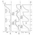
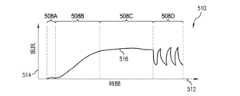
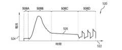
図4は、封止されている生物組織へ提供される電力を制御するために使用される電気療法スケジュールまたは計画の非限定的な例を示すグラフである。図4で、グラフ200は、水平軸202、垂直軸204A~204C、および関数関係206A~206Cを有する。水平軸202は、時間(秒)を示す。水平軸は、時間t0~t8を有し、これは、電気外科機器によって係合された生物組織を治療するための電気療法信号を生成する方法100に関する議論で開示される呼掛け段階、乾燥段階、および封止段階間の遷移時間を意味する。これらの段階(呼掛け段階、第1の乾燥段階、および封止段階)もまた、グラフ200の様々な場所に示されている。図4のグラフは、説明の目的のみを意味することに留意されたい。図4のグラフは応答の一例を示し、異なる組織は異なる形で反応する可能性がある。FIG. 4 is a graph showing a non-limiting example of an electrotherapy schedule or regimen used to control power delivered to biological tissue being sealed. In FIG. 4,
垂直軸204Aは、電気外科機器によって係合された生物組織へ提供される電力(W)を示す。関数関係206Aは、図3A~図3Bに示す方法100の非限定的な例に基づいて生成される電気療法信号に対応する電力/時間関係の非限定的な例を示す。垂直軸204Bは、係合された生物組織によって伝導される電流を示す。関数関係206Bは、方法100を介して生成された電気療法信号が提供される係合された生物組織によって伝導される電流に関する電流/時間関係を示す。垂直軸204Cは、係合された生物組織の電気抵抗を示す。関数関係206Cは、方法100を介して生成された電気療法信号が提供される係合された生物組織の電気抵抗に対応する電気抵抗/時間関係を示す。
いくつかの例では、関数関係206Aは、呼掛け段階、乾燥段階、および封止段階を含む事前定義された電力曲線とすることができる。図4に示す特有の非限定的な例では、乾燥段階は、第1および第2の乾燥区間を示す。時間t0~t1で、電力/時間関係206Aは呼掛け段階を示す。いくつかの例では、呼掛け段階の持続時間は、係合された生物組織の基準測定値を得るために必要とされる長さである。たとえば、呼掛け段階の持続時間は、1.0、0.5、0.25、または0.1秒より小さくすることができる。グラフ200に示すように、呼掛け段階は、電力P1(W)を有する一定電力スケジュールまたは計画である。時間t0~t1で、電流/時間関係206Bは、係合された生物組織によって伝導される呼掛けの電流が急速に上昇し、それに続いて電流が横ばい状態になり、次いで電流がわずかに減少することを示す。電力はこの呼掛け段階全体にわたって一定になるように制御されるため、係合された生物組織に印加される電圧は、電流/時間関係に反比例する(加法の意味ではなく乗法の意味)。組織内の流体の温度が上昇すると、係合された生物組織の抵抗は最初に減少することがある。このとき呼掛け段階は初めて実行されるため、測定された電気抵抗は、以前に測定された最小の抵抗以上であり、したがってこの方法は第1の乾燥段階へ進む。In some examples,
時間t1~t2で、電力/時間関係206Aは、乾燥段階の第1の区間を示す。グラフ200に示すように、乾燥段階の第1の乾燥区間は、電力P1からP2(W)へ単調に増大する電力スケジュールまたは計画である。時間t1~t2で、電流/時間関係206Bは、乾燥段階の第1の区間全体にわたって、係合された生物組織によって伝導される電流が増大することを示す。電力は、乾燥スケジュールまたは計画に従って、乾燥段階のこの第1の区間全体にわたって制御されるため、係合された生物組織に印加される電圧と電流/時間関係との積は、電力/時間関係206Aをもたらすはずである。図示しないが、いくつかの例では、電気抵抗/時間関係206Cは、係合された生物組織の電気抵抗は、組織が温まるにつれて、最初に減少する可能性があるが、次いで乾燥段階の第1の区間中に組織が乾燥し始めると、増大することができることを示すことができる。そのように増大する電気抵抗は、係合された生物組織の乾燥を示すことができる。電力/時間関係206Aが所定の閾値まで上昇する前に、電流が以前に測定された最大電流の割合を下回るため、この方法は乾燥段階の第2の区間へ進む。乾燥段階のこの第1の区間中に電流が以前に測定された最大電流の割合を下回った場合、乾燥段階の次の第2の区間は必要ないはずである(たとえば、迂回することができる)。From time t1 to t2 , the power/
時間t2~t3で、電力/時間関係206Aは、乾燥段階の第2の区間を示す。グラフ200に示すように、乾燥段階の第2の区間は、電力P2からP3(W)へ単調に増大する電力スケジュールまたは計画である。図3Aおよび図3Bに関して上述した技法を使用して、図2の制御回路48などの制御回路は、生物組織の測定された電気パラメータの変化の関数としてのエネルギー送達の増分変化に従って、療法段階の一部分中に生物組織へ提供される療法信号のエネルギー送達を制御することができる。たとえば、制御回路は、電流の関数として電力を増分的に修正することができる。いくつかの例では、電流の関数は、測定された電流の瞬時変化の関数である。いくつかの例では、測定された電流の瞬時変化の関数は、線形関数である。他の例では、制御回路は、抵抗の関数として電力を増分的に修正することができる。From time t2 to t3 , the power/
時間t2~t3で、電流/時間関係206Bは、係合された生物組織によって伝導される電流が、乾燥段階の第2の区間の始めに増大するが、ピークに達し、次いで第2の乾燥段階の終わりには減少することを示す。乾燥段階の第2の区間は必要とされないことに留意されたい。いくつかの例では、電力は、乾燥段階のこの第2の区間全体にわたって、係合された生物組織に印加される電圧と電流/時間関係との積が特定の電力/時間関係206Aをもたらすことができるように制御することができる。From time t2 to t3 , the current/
いくつかの例では、乾燥段階の第2の区間は単調に増大するが、乾燥段階の第1の区間より遅い速度で増大する。他の例では、乾燥段階の第2の区間は、提供された電力が所定の最大レベルに等しくなるまで線形に増大し、その後、提供された電力は一定に保持される。電流の減少ΔI1、たとえば測定された電流の変化(図3Aのブロック126など)の結果、測定された最大電流の所定の割合より小さい電流が生じるため、この方法は呼掛け段階へ戻り、これは時間t3に示されている。言い換えれば、電流の変化ΔI1により、この方法は時間t3で呼掛け段階に入る。図4に示す非限定的な例では、方法を呼掛け段階に入れる電流の変化ΔI1は、時間t2の後であることに留意されたい。しかし、他の例では、方法を呼掛け段階に入れる電流の変化ΔI1は、時間t1後、乾燥段階の第1の区間中とすることができ、乾燥段階の第2の区間は必要とされない。しかし、代わりに電流の減少ΔI1が、測定された最大電流の所定の割合より小さい場合、この方法は乾燥段階に残るはずである。In some examples, the second leg of the drying phase increases monotonically, but at a slower rate than the first leg of the drying phase. In another example, the second leg of the drying phase increases linearly until the power provided equals a predetermined maximum level, after which the power provided is held constant. A decrease in current ΔI1, eg, a change in the measured current (such as
図4に見られるように、いくつかの例では、事前定義された電力曲線206Aは、t1~t2およびt2~t3に示すように、2つ以上の線形部分を含むことができる。As seen in FIG. 4, in some examples, the
時間t3~t4で、電力/時間関係206Aは、再び呼掛け段階を示す。グラフ200に示すように、呼掛け段階は、電力P1(W)の一定電力スケジュールである。電力はこの呼掛け段階全体にわたって一定になるように制御されるため、係合された生物組織に印加される電圧は、電流/時間関係に反比例する(加法の意味ではなく乗法の意味)。電気抵抗/時間関係206Cは、呼掛け段階のこの実行全体にわたって、係合された生物組織の電気抵抗が減少していることを示す。電気抵抗が減少する結果、組織内の流体の凝縮または組織への流体の移動が生じる可能性がある。測定された電気抵抗は、基準抵抗と所定のデルタ抵抗との和以下であるため、この方法は再び第1の乾燥段階へ進む。At times t3 -t4 , the power/
時間t4~t5で、電力/時間関係206Aは、乾燥段階の別の第1の区間を示す。時間t4~t5の電力/時間関係は、時間t1~t2の電力/時間関係206Aに類似しており、簡潔にする目的で、再び詳細には説明しない。From time t4 to t5 the power/
時間t5~t6で、電力/時間関係206Aは、乾燥段階の別の第2の区間を示す。時間t5~t6の電力/時間関係は、時間t2~t3の電力/時間関係206Aに類似しており、簡潔にする目的で、再び詳細には説明しない。電力は乾燥段階のこの第2の区間全体にわたって一定になるように制御されるため、係合された生物組織に印加される電圧と電流/時間関係との積は、電力/時間関係206Aをもたらすはずである。電流の減少ΔI2、たとえば測定された電流の変化(図3Bのブロック142など)が、測定された最大電流の所定の割合より小さい場合、この方法は呼掛け段階へ戻る。From time t5 to t6 the power/
時間t6~t7で、電力/時間関係206Aは、別の呼掛け段階を示す。時間t6~t7の電力/時間関係は、時間t3~t4の電力/時間関係206Aに類似しており、簡潔にする目的で、再び詳細には説明しない。ここで、測定された電気抵抗は基準抵抗と所定のデルタ抵抗との和より大きいため、この方法は封止段階へ進む。From time t6 to t7 , power/
時間t7~t8で、電力/時間関係206Aは、封止段階を示す。グラフ200に示すように、封止段階は、電力P1から電力P3(W)へ単調に増大する電力スケジュールまたは計画である。時間t7~t8で、電流/時間関係206Bは、封止段階全体にわたって、係合された生物組織によって伝導される電流が増大することを示す。電気抵抗/時間関係206Cは、係合された生物組織の電気抵抗が、封止段階のこの性能を増大させていることを示す。電気抵抗が増大する結果、係合された生物組織の乾燥をもたらし、それによって封止をもたらすことができる。ここで、測定された電気抵抗は所定の終了抵抗より大きいため、封止段階が終了され、この方法は終了する。From time t7 to t8 , power/
電気療法信号の予測段階制御(図5~図6)
電気外科処置は、1つ以上の電気療法段階を有することができる。たとえば、電気外科的組織封止技法は、呼掛け段階、乾燥段階、および/または封止段階を有することができる。これらの各電気療法段階中に、たとえば呼掛け信号、加熱信号、乾燥信号、焼灼信号などの対応する電気療法信号を、電気外科機器によって係合された生物組織へ提供することができる。係合された生物組織へ提供された電気療法信号は、実行されている技法および/または特有の組織に合わせて調整することができる。したがって、各電気外科信号は、異なる処置、異なる組織タイプおよび数量、ならびに異なる電気療法段階に対して異なることができる。異なる電気療法信号のこれらの違いは、異なる電気療法スケジュールおよび/または異なる段階制御基準を使用して得ることができる。異なる電気療法スケジュール間の違いは、制御される電気パラメータの違い、および/または段階制御基準の違いに由来することができる。上述したように、制御される電気パラメータの違いは、電気療法信号の皮相電力(VA)、有効電力(W)、電圧(V)、および/または電流(A)を含む。段階制御基準は、段階の開始および終了のための基準、ならびに段階内制御のための基準を含む。そのような段階制御基準は、同時段階制御基準および予測段階制御基準を含む。Predictive Step Control of Electrotherapy Signals (FIGS. 5-6)
An electrosurgical procedure can have one or more electrotherapy stages. For example, an electrosurgical tissue sealing technique can have an interrogation phase, a drying phase, and/or a sealing phase. During each of these electrotherapy phases, a corresponding electrotherapy signal, such as an interrogation signal, a heating signal, a drying signal, an ablation signal, etc., can be provided to the biological tissue engaged by the electrosurgical instrument. The electrotherapy signal provided to the engaged biological tissue can be tailored to the technique being performed and/or the specific tissue. Thus, each electrosurgical signal can be different for different treatments, different tissue types and quantities, and different electrotherapy phases. These differences in different electrotherapy signals can be obtained using different electrotherapy schedules and/or different phasing criteria. Differences between different electrotherapy schedules can result from differences in controlled electrical parameters and/or differences in phasing control criteria. As noted above, differences in controlled electrical parameters include apparent power (VA), real power (W), voltage (V), and/or current (A) of the electrotherapy signal. Phase control criteria include criteria for phase initiation and termination, as well as for intra-phase control. Such tiering criteria include simultaneous tiering criteria and predictive tiering criteria.
同時段階制御は、実時間測定を使用して段階を制御することによって実行される。予測段階制御は、基準時間に得られた基準測定値を使用して将来の段階制御基準を生成することによって実行される。たとえば、乾燥段階前または乾燥段階中に得られた組織抵抗測定値を使用して、乾燥段階を継続するための持続時間を生成することができる。いくつかの例では、組織抵抗測定値は、複数の所定の電気療法スケジュールのうちの1つを選択するために使用することができる。複数の所定の電気療法スケジュールのうち、選択された電気療法スケジュールは、次の電気療法段階で使用することができる。 Simultaneous step control is performed by using real-time measurements to control the steps. Predictive step control is performed by using reference measurements taken at reference times to generate future step control references. For example, tissue resistance measurements obtained before or during the drying phase can be used to generate the duration for which the drying phase continues. In some examples, tissue resistance measurements can be used to select one of a plurality of predetermined electrotherapy schedules. A selected electrotherapy schedule of the plurality of predetermined electrotherapy schedules can be used in the next electrotherapy phase.
組織抵抗の基準測定値は、たとえば血管サイズを示すことができる。異なる電気療法スケジュールもしくは計画、および/または異なる段階制御基準を使用して、異なるサイズの血管を加熱することができる。血管サイズに合わせてカスタマイズされた適当な電気療法スケジュールまたは計画は、封止をより確実にし、近隣組織への外傷をより少なくすることができる。係合された血管の適切な封止を確実にするために、封止すべき血管のサイズに従って、電気療法スケジュールを調整することができる。血管サイズは、係合された血管の測定された基準抵抗に基づいて推定することができる。次いで、血管封止は、係合された血管の測定された基準抵抗に基づいて決定された電気療法スケジュールに従って進行することができる。 A baseline measurement of tissue resistance can indicate, for example, vessel size. Different electrotherapy schedules or regimens and/or different grading criteria can be used to heat vessels of different sizes. A suitable electrotherapy schedule or plan, customized for vessel size, can result in a more secure seal and less trauma to nearby tissue. To ensure proper sealing of the engaged vessel, the electrotherapy schedule can be adjusted according to the size of the vessel to be sealed. Vessel size can be estimated based on the measured baseline resistance of the engaged vessel. Vessel sealing can then proceed according to an electrotherapy schedule determined based on the measured baseline resistance of the engaged vessel.
とりわけ、検出された組織のサイズに基づいてエネルギーを予測および送達する技法について、図6に関して後述する。図2の電気外科ジェネレータ12などの電気外科ジェネレータが、電気外科デバイスを介してエネルギーの初期印加を生物組織へ送達した後、図2の制御回路48などの制御回路、および図2の測定回路46などの測定回路が、ある時点の組織インピーダンスを測定または計算することができる。次いで、制御回路は、電気外科デバイスの顎部間などで電気外科デバイスに接触している組織のタイプ、たとえば小さい血管かまたは大きい血管かを判定し、次いで検出された組織のタイプに合わせてエネルギーを送達することができる。 Among other things, techniques for predicting and delivering energy based on detected tissue size are described below with respect to FIG. After an electrosurgical generator, such as
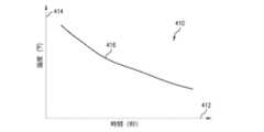
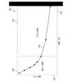
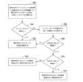
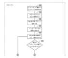
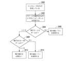
図6は、電気外科機器によって係合された生物血管のサイズに対応する電力スケジュールを使用する生物学的血管封止方法の流れ図である。図6の方法は、3つの療法段階を使用しており、段階1は呼掛け段階、段階2は脱水または乾燥段階、段階3は血管接合段階である。段階1で、図1の電気外科システム10などの電気外科システムは、エラー検査を実行し、呼掛けスケジュールなどに従って呼掛け信号を生成して、係合された組織へ呼掛け信号を送達することができる。図6には電圧制御として説明するが、制御回路は、電力制御式の技法または電圧制御式の技法を使用してエネルギーを送達することができる。電圧制御式の技法では、電流の上限を定めることができるが、電流は、応答インピーダンスに従って自由に動くことが可能であり、それにより可変電力送達を可能にすることができる。 FIG. 6 is a flow diagram of a biological vessel sealing method using a power schedule corresponding to the size of the biological vessel engaged by the electrosurgical instrument. The method of FIG. 6 uses three stages of therapy:
本開示の技法を使用することで、この方法は、制御回路が段階を終了させるためにどの基準を使用するかを判定することなく、段階2などの段階を始めることができる。たとえば、以下でより詳細に説明するように、この方法は段階2を開始し、制御回路および測定回路は、組織のインピーダンス測定値を判定することができる。これに応答して、制御回路は、段階2を時間測定値に基づいて終了させるか、または反復インピーダンス測定値に基づいて終了させるかを判定することができる。このようにして、制御回路は、段階2をどのように終了させるかに関して2つの別個の基準を有するが、2つの基準のうちのどちらを使用するかを事前に選択することなく、段階2に入る。 Using the techniques of this disclosure, the method can begin a stage, such as
ブロック1900で、段階1が開始し、ブロック1901で、制御回路および測定回路は、時間T0で初期インピーダンス値R0を測定および/または計算することができる。ブロック1902で、制御回路は、段階2に対する電圧の傾斜率または勾配を設定することができる。電圧設定は、一定の電圧、増大する電圧、または減少する電圧とすることができる。電力制御式の実装の場合も、制御回路は、段階2に対して電力の傾斜率または勾配を設定することができる。電力は、一定の電力、増大する電力、または減少する電力とすることができる。段階1の出力は、初期インピーダンス値R0である。
ブロック1904で、段階2が始まる。ブロック1906で、設定された期間後、制御回路および測定回路は、基準インピーダンスR1を測定または計算することができる。組織のインピーダンスは、初期インピーダンスR0からインピーダンスR1へ変化している可能性がある。インピーダンスR1を測定して、段階2が開ループ段階である(タイマが切れることなどによって、時間基準に基づいて終了した)か、または閉ループ段階である(たとえばインピーダンス基準に基づいて終了した)かを判定する。より乾燥した組織の場合、段階2を開ループとして実行することが望ましく、より湿った組織の場合、段階2を閉ループとして実行することが望ましい。 At
ブロック1908で、制御回路は、インピーダンスR1が閾値インピーダンス値Ra以上であるかどうかを判定することができる。いくつかの例では、インピーダンスRaは、絶対インピーダンスとすることができる。他の例では、インピーダンスRaは、測定された初期インピーダンスR0からの所定の上昇など、デルタ値とすることができる。いくつかの例では、インピーダンスRaは、約90オームとすることができる。 At
いくつかの例では、測定されたインピーダンスR1と閾値インピーダンスRaとを比較することに加えて、またはその代わりに、制御回路は、何らかの他の測定されたパラメータと閾値パラメータとを比較することができる。たとえば、制御回路は、測定された位相角と閾値位相角とを比較することができる。使用することができる他のパラメータの例には、それだけに限定されるものではないが、ある期間にわたって送達されるエネルギー、電流の引込み、組織温度などが含まれる。 In some examples, in addition to or instead of comparing the measured impedance R1 to the threshold impedance Ra, the control circuit may compare some other measured parameter to the threshold parameter. . For example, the control circuit can compare the measured phase angle to a threshold phase angle. Examples of other parameters that can be used include, but are not limited to, energy delivered over time, current draw, tissue temperature, and the like.
制御回路が、インピーダンスR1がインピーダンスRa以上であると判定した場合(ブロック1908の「はい」の分岐)、制御回路は、ブロック1910で段階2を開ループとして実行することができ、時間T2でタイマが切れるまで、電力の送達を継続することができる。ブロック1912で、段階2は、時間間隔などによって、時間基準に基づいて終了する。 If the control circuit determines that impedance R1 is greater than or equal to impedance Ra (the "yes" branch of block 1908), then the control circuit may execute
しかし、制御回路が、インピーダンスR1がインピーダンスRa以下であると判定した場合(ブロック1908の「いいえ」の分岐)、制御回路は、段階2を、ブロック1914で開始する閉ループとして実行することができる。ブロック1916で、制御回路は、設定された時間間隔で、インピーダンスR2Nを測定することができる。ブロック1918で、制御回路は、現在のインピーダンス測定値R2Nがインピーダンス閾値R2X以上であるかどうかを判定することができる。 However, if the control circuit determines that impedance R1 is less than or equal to impedance Ra (“no” branch of block 1908), then the control circuit may perform
制御回路が、インピーダンスR2NがインピーダンスR2X以下であると判定した場合(ブロック1918の「いいえ」の分岐)、この方法は、電力の印加を継続することができ、ブロック1914へ戻ることができる。この方法は、ブロック1916で、ある時間間隔でインピーダンス測定を繰り返すことができ、ブロック1918で、新しいインピーダンス測定値が閾値以上であるかどうかを判定することができる。このようにして、この方法は、電力の印加を継続することができ、インピーダンス測定値と閾値インピーダンス値とを反復的に比較することができる。 If the control circuit determines that impedance R2N is less than or equal to impedance R2X (“no” branch of block 1918), the method may continue to apply power and may return to block 1914. The method may repeat the impedance measurements at a time interval at
制御回路が、インピーダンスR2N(または必要な場合、後のインピーダンス測定値のいずれか)がインピーダンスR2X以上であると判定した場合(ブロック1918の「はい」の分岐)、制御回路は、ブロック1920で、インピーダンス基準(開ループプロセスに関して上述した時間基準とは対照的)に基づいて、段階2を終了させることができる。 If the control circuit determines that the impedance R2N (or any of the subsequent impedance measurements, if desired) is greater than or equal to the impedance R2X (the "yes" branch of block 1918), the control circuit in block 1920:
制御回路が段階2を終了させた後、段階2が時間に基づいて終了したか、またはインピーダンス測定値に基づいて終了したかにかかわらず、制御回路は、ブロック1922で、インピーダンス測定値R3を計算および記憶することができる。次に、ブロック1924で、制御回路は、現在のインピーダンス測定値R3がインピーダンス閾値RX以下であるかどうかを判定することができる。 After the control circuit terminates
制御回路が、インピーダンスR3がインピーダンスRX以上であると判定した場合(ブロック1924の「はい」の分岐)、組織は小さい血管であり、この方法は、ブロック1926で、段階3を開始することができる。ブロック1928で、制御回路は、段階3を開ループとして実行することができ、時間T3でタイマが切れるまで、電力の送達を継続することができる。ブロック1930で、段階3は、時間間隔に基づいて終了する。 If the control circuit determines that impedance R3 is greater than or equal to impedance RX (“yes” branch of block 1924), then the tissue is a small vessel and the method can begin phase 3 at
しかし、制御回路が、インピーダンスR3がインピーダンスRX以下であると判定した場合(ブロック1924の「いいえ」の分岐)、組織は大きい血管であり、この方法は、ブロック1932で段階3を開始することができ、制御回路は、段階3を閉ループとして実行することができる。ブロック1934で、制御回路は、設定された時間間隔で、インピーダンスR3Nを測定することができる。ブロック1936で、制御回路は、現在のインピーダンス測定値R3Nがインピーダンス閾値R3X以上であるかどうかを判定することができる。 However, if the control circuit determines that impedance R3 is less than or equal to impedance RX (“No” branch of block 1924), then the tissue is a large vessel and the method may begin phase 3 at
制御回路が、インピーダンスR3NがインピーダンスR3X以下であると判定した場合(ブロック1936の「いいえ」の分岐)、ブロック1938で、制御回路は、最大時間限界に到達したかどうかを判定することができる。制御回路が、最大時間限界に到達したと判定した場合(ブロック1938の「はい」の分岐)、制御回路は、ブロック1940で、段階3を終了させることができる。いくつかの例では、時間限界は、段階1の開始からの経過時間とすることができる。 If the control circuit determines that impedance R3N is less than or equal to impedance R3X (“No” branch of block 1936), then at
しかし、制御回路が、最大時間限界に到達していないと判定した場合(ブロック1938の「いいえ」の分岐)、制御回路は、電力の印加を継続することができ、ブロック1934へ戻ることができる。この方法は、ブロック1934で、ある時間間隔でインピーダンス測定を繰り返すことができ、ブロック1936で、新しいインピーダンス測定値が閾値インピーダンス値R3X以上であるかどうかを判定することができる。このようにして、この方法は、電力の印加を継続することができ、インピーダンス測定値と閾値インピーダンス値R3Xとを反復的に比較することができる。 However, if the control circuit determines that the maximum time limit has not been reached (“No” branch of block 1938), the control circuit may continue to apply power and may return to block 1934. . The method may repeat the impedance measurements at a time interval at
制御回路が、インピーダンスR3NがインピーダンスR3Xより大きいと判定した場合(ブロック1936の「はい」の分岐)、ブロック1942で、制御回路は、インピーダンス測定値(段階の開ループプロセスに関して上述した時間基準とは対照的)に基づいて、段階3を終了させることができる。 If the control circuit determines that the impedance R3N is greater than the impedance R3X (the "yes" branch of block 1936), then at
係合された生物組織の測定された電気抵抗の補正(図7A~図7Bおよび図9)
上述した様々な電気測定値は、電気療法スケジュールの判定および/または段階制御基準の判定で使用することができる。したがって、正確な測定値は、その療法目的でうまくいく電気療法信号の生成を容易にする。電気外科機器および電気外科機器によって係合された生物組織の温度は、係合された生物組織の電気測定値に影響を与える。そのような温度/測定値の関係は、電気療法スケジュールおよび/または段階制御基準を判定するとき、そのような電気測定値の使用に不特定性および/または複雑さをもたらす可能性がある。たとえば、係合された組織および/または電気外科機器が異なる温度であるときに得られる係合された組織の2つの電気測定値の比較は、複雑になる可能性がある。Correction of Measured Electrical Resistance of Engaged Biological Tissue (FIGS. 7A-7B and 9)
The various electrical measurements described above can be used in determining an electrotherapy schedule and/or determining phasing control criteria. Accurate measurements therefore facilitate the generation of successful electrotherapy signals for that therapy purpose. The temperature of the electrosurgical instrument and the biological tissue engaged by the electrosurgical instrument affects electrical measurements of the engaged biological tissue. Such temperature/measurement relationships can introduce ambiguity and/or complexity into the use of such electrical measurements when determining electrotherapy schedules and/or staging criteria. For example, comparing two electrical measurements of engaged tissue obtained when the engaged tissue and/or electrosurgical instrument are at different temperatures can be complicated.
いくつかの例は、電気外科機器および/または生物組織の温度を相殺するように、係合された組織の電気測定値を補正する。たとえば、生物組織の測定された電気抵抗は、電気外科機器の実際の温度測定値に基づいて補正することができる。いくつかの例では、電気外科機器は、生物組織に係合する遠位端と熱的に連通する温度センサを装備する。他の例では、生物組織の測定された電気抵抗はまた、様々な間接的測定に基づく組織および/または電気外科機器の予測温度に基づいて補正することもできる。たとえば、電力が生物組織へ送達された基準時間と測定時間との間の時間間隔に基づいて、測定された組織抵抗を補正することができる。いくつかの例では、測定された組織抵抗は、電気測定前に係合された組織へ提供されたエネルギーの計算に基づいて補正することができる。 Some examples correct electrical measurements of engaged tissue to offset temperature of the electrosurgical instrument and/or biological tissue. For example, the measured electrical resistance of biological tissue can be corrected based on the actual temperature measurements of the electrosurgical instrument. In some examples, an electrosurgical instrument is equipped with a temperature sensor in thermal communication with a distal end that engages biological tissue. In other examples, the measured electrical resistance of biological tissue can also be corrected based on the predicted temperature of the tissue and/or the electrosurgical instrument based on various indirect measurements. For example, the measured tissue resistance can be corrected based on the time interval between the reference time that power was delivered to the biological tissue and the measurement time. In some examples, the measured tissue resistance can be corrected based on a calculation of the energy delivered to the engaged tissue prior to the electrical measurement.
図7Aは、測定された組織抵抗を鉗子の顎部温度の関数として示すグラフである。図7Aで、グラフ400は、水平軸402、垂直軸404、および電気抵抗/温度関係406を含む。水平軸402は、鉗子の顎部温度を示す。垂直軸404は、図1に示す鉗子14などの鉗子の対置可能な顎部材間に締め付けられた組織の測定された電気抵抗を示す。電気抵抗/温度関係406は、様々な温度まで加熱された対置可能な顎部材によって締め付けられた特有の生物組織の測定値を示す。電気抵抗/温度関係406は、単調に減少する関数を示し、顎部温度が上昇するにつれて、測定された電気抵抗は減少する。測定された電気抵抗のそのような変動は、組織温度に対する電気抵抗依存性、組織-液体段階、顎部-組織インターフェース、顎部温度などを含む多くの要因に由来することができる。 FIG. 7A is a graph showing measured tissue resistance as a function of forceps jaw temperature. 7A,
測定された組織抵抗のそのような変動は、そのような測定された電気抵抗を使用して電気療法スケジュールおよび/または段階制御基準を判定するとき、不特定性および/または複雑さをもたらす可能性がある。電気抵抗依存性のいくつかは、生物組織に対する療法効果を示さないため、望ましくない。したがって、これらの望ましくない依存性の補償は、そのような電気抵抗測定値の品質を改善することができる。生物組織の電気測定値を補償する様々な方法を実行して、電気療法治療の療法作用をより良好に示す測定を提供することができる。 Such variations in measured tissue resistance can introduce ambiguity and/or complexity when using such measured electrical resistance to determine electrotherapy schedules and/or staging criteria. There is Some of the electrical resistance dependencies are undesirable because they have no therapeutic effect on biological tissue. Compensation for these undesirable dependencies can therefore improve the quality of such electrical resistance measurements. Various methods of compensating electrical measurements of biological tissue can be implemented to provide measurements that are more indicative of the therapeutic effect of electrotherapy treatment.
図7Bは、顎部温度と電力印加の終了後の時間との関係を示すグラフである。図7Bで、グラフ410は、水平軸412、垂直軸414、および温度-時間関係416を含む。水平軸412は、電気療法信号の印加が生物組織へ提供された後の時間を示す。この治療後の時間中、電力は生物組織へ送達されない。垂直軸414は、電気療法信号を組織へ提供するために使用される鉗子の対置可能な顎部材の測定された温度を示す。温度-時間関係416は、様々な治療後時間における顎部温度の測定値を示す。温度-時間関係416は、漸近的に室温に接近する時間の単調に減少する関数である。そのような温度-時間関係は、減衰速度を示す時定数を特徴とすることができる。 FIG. 7B is a graph showing the relationship between jaw temperature and time after the end of power application. In FIG. 7B,
グラフ400および410に示す関係は、電力印加および電力印加後の持続時間の関数として顎部温度をモデル化するときに使用することができる。たとえば、電気外科機器によって係合された生物組織によって放散される電力を使用して、その生物組織の温度、ならびに電気外科機器の係合部分(たとえば、図1に示す対置可能な顎部材36および38)の温度を予測することができる。そのような顎部温度-電力印加関係は、理論的(たとえば、対置可能な顎部材の係合範囲内の組織体積を使用)ならびに実験的(たとえば、機器を特徴付けることによる)に判定することができる。いくつかの例では、たとえば顎部材の係合範囲内の組織体積を判定するときに、係合された顎部材の位置を使用することができる。いくつかの例では、理論的および実験的な特徴付けの組合せを使用して、顎部温度と電力印加との間の関係をモデル化することができる。顎部温度-治療後時間も同様に、実験的および/または理論的に特徴付けることができる。 The relationships shown in
さらに、生物組織に対する療法作用を示さないことから望ましくない電気抵抗依存性も、実験的および/または理論的に特徴付けることができる。次いで、これらの様々な特徴付けまたはモデルを組み合わせて、測定された抵抗値に基づいて、補償された抵抗値を判定することができる。たとえば、生物組織への電気療法信号の印加中に得られた組織抵抗の測定は、電気療法スケジュールに基づいて計算された顎部温度を補償のために使用することができる。生物組織への電気療法信号の印加後、治療後持続時間を使用して、組織抵抗の測定値を補償することができる。 In addition, electrical resistance dependence, which is undesirable because it has no therapeutic effect on biological tissue, can also be characterized experimentally and/or theoretically. These various characterizations or models can then be combined to determine a compensated resistance value based on the measured resistance value. For example, measurements of tissue resistance obtained during application of electrotherapy signals to biological tissue can be used to compensate for jaw temperatures calculated based on the electrotherapy schedule. After application of the electrotherapy signal to biological tissue, the post-treatment duration can be used to compensate the measurement of tissue resistance.
図8は、電気抵抗補償と電力印加後の時間との関係を示すグラフである。図8で、グラフ420は、水平軸422、垂直軸424、およびデルタ抵抗/時間関係426を含む。水平軸422は、電気療法信号の印加が生物組織へ提供された後の時間を示す。この治療後時間中、電力は生物組織へ送達されない。垂直軸424は、測定された組織抵抗を補償するために必要とされるデルタ抵抗を示す。いくつかの例では、加算デルタ抵抗補正を使用する代わりに、乗法因子を使用することができる。デルタ抵抗/時間関係426は、様々な治療後時間に顎部温度を補償するために必要とされるデルタ抵抗補正係数を示す。デルタ抵抗/時間関係426は、漸近的にゼロに接近する時間の単調に減少する関数である。 FIG. 8 is a graph showing the relationship between electrical resistance compensation and time after power application. In FIG. 8,
一例では、電気外科機器が所定の閾値より低温であるときではなく、電気外科機器が所定の閾値より高温であるとき、測定された組織抵抗を補償することができる。図8は、これら2つの補償方式(たとえば、高温および低温機器方式)を区切る動作区間428および430を示す。動作区間428は、生物組織への電気療法信号の印加直後の時間から、生物組織への電気療法信号の印加後の所定の時間まで及ぶ。この高温機器方式中、測定された組織抵抗値に所定のデルタ抵抗値を加算することによって、組織抵抗の測定値が補償される。図8に示す例では、高温機器方式から低温機器方式への遷移を区切る時間は、治療後約30秒である。低温機器方式では、組織抵抗の測定値の補償は実行されない。 In one example, the measured tissue resistance can be compensated for when the electrosurgical instrument is warmer than a predetermined threshold rather than when the electrosurgical instrument is cooler than a predetermined threshold. FIG. 8
初期インピーダンスの修正(図9)
図2の電気外科ジェネレータ12の制御回路48などの電気外科ジェネレータの制御回路は、予測アルゴリズムを使用して、電気療法信号を生成し、図1の鉗子14の顎部間などで電気外科デバイスに係合された生物組織へ送達することができる。予測アルゴリズムは、複数の段階を含むことができる。たとえば、段階1は、低電力エネルギーを使用して、血管インピーダンスおよび様々なエネルギー送達パラメータに最初にアクセスすることができる。段階1で判定された初期インピーダンスに基づいて、システムは、封止すべき血管のサイズを判定し、段階2で血管組織を乾燥させるためのパラメータを設定し、段階3で血管を封止するための適切なエネルギーレベルおよび持続時間を提供することができる。Modification of initial impedance (Fig. 9)
Control circuitry of an electrosurgical generator, such as
しかし、血管サイズを正確に予測することは困難な可能性がある。たとえば、血管サイズを判定するために使用することができる初期血管インピーダンスは、電気外科デバイスの顎部温度による影響を受ける可能性がある。顎部は、ユーザが第1の血管を封止した直後に第2の血管を封止しようとした場合、高い温度を有する可能性がある。高い温度は、初期血管インピーダンス測定値に影響を与える可能性がある。 However, accurately predicting vessel size can be difficult. For example, the initial vascular impedance that can be used to determine vessel size can be affected by the jaw temperature of the electrosurgical device. The jaws may have a high temperature if the user attempts to seal the second vessel immediately after sealing the first vessel. High temperatures can affect initial vascular impedance measurements.
本発明者らは、初期インピーダンス測定値の温度作用を低減させて血管サイズ予測を改善する必要を認識した。以下でより詳細に説明するように、本発明者らは、いくつかの例では、顎部に結合された温度センサを使用して、顎部の温度を判定することができ、次いで顎部温度に基づく補正係数を使用して、測定されたインピーダンスを修正することができることを認識した。他の例では、本発明者らは、以前の起動からの経過時間または以前の起動の電気特性のうちの一方または両方に基づく補正係数を使用して、測定されたインピーダンスを修正することができることを認識した。修正されたインピーダンス値を使用して、電気外科システムは、血管のサイズをより正確に予測することができ、これを使用して、電気外科ジェネレータに対する設定を判定することができる。 The inventors have recognized the need to reduce the temperature effect of initial impedance measurements to improve vessel size prediction. As described in more detail below, the inventors have found that in some examples, a temperature sensor coupled to the jaw can be used to determine the temperature of the jaw and then determine the temperature of the jaw. We have recognized that we can correct the measured impedance using a correction factor based on In another example, we can modify the measured impedance using a correction factor based on one or both of the elapsed time since the previous activation or the electrical characteristics of the previous activation. recognized. Using the modified impedance values, the electrosurgical system can more accurately predict vessel size, which can be used to determine settings for the electrosurgical generator.
図9は、電力印加後に組織インピーダンスの測定値を補償することができる生物学的血管封止方法の流れ図である。ブロック2000で、制御回路48および測定回路46(どちらも図2)などの制御回路および測定回路が、段階1で、図1の鉗子14などの電気外科デバイスに係合された生物組織の初期インピーダンスR0を測定することができる。ブロック2002で、制御回路および測定回路は、段階1で、電気外科デバイスの顎部の温度を、顎部に結合された温度センサを使用して測定することができる。 FIG. 9 is a flow diagram of a biological vessel sealing method that can compensate for tissue impedance measurements after power application. At
ブロック2004で、測定されたインピーダンスおよび測定された顎部温度を使用して、制御回路は、ルックアップテーブルなどの記憶されているデータログまたはセットに照会し、顎部の温度を相殺するための初期インピーダンスR0の修正である調整または補正されたインピーダンスを判定または選択することができる。 At
ブロック2006で、制御回路は、判定された調整済みインピーダンスを使用して、血管サイズを判定することができる。たとえば、アルゴリズムまたは別の記憶されているデータセットを使用して、制御回路は、調整済みインピーダンスを使用して、血管サイズを判定することができる。 At
次いで、ブロック2008で、制御回路は、判定された血管サイズを使用して、電気外科ジェネレータが生成して血管の生物組織へ送達する電気外科信号を定義する様々な電気パラメータを判定することができる。いくつかの例では、血管サイズは、小さい血管または大きい血管になるように判定することができ、それら2つの血管サイズに対応する2つの電気外科信号設定が存在することができる。他の例では、一連の血管サイズおよびそれらの血管サイズに対応する電気外科設定が存在することができる。 Then, at
ブロック2010で、制御回路は、判定された信号設定を使用して、封止を実行するように、血管への電気外科信号の送達を制御することができ、この方法は、ブロック2012で終了することができる。 At
ブロック2014に示すように、顎部温度を使用する代わりに、いくつかの例は、最終起動からの経過時間を記憶することができる。経過時間が長ければ長いほど、顎部がさらに冷めている。このようにして、最終起動からの経過時間は、顎部温度の代わりに使用することができる。 As shown in
ブロック2004で、制御回路は、測定された初期インピーダンスR0および最終起動からの経過時間を使用して、調整済みインピーダンスを判定することができる。いくつかの例では、制御回路は、経過時間と時間T、たとえば20秒とを比較することができ、経過時間がT以上である場合、制御回路は、初期インピーダンスを調整済みインピーダンスとして使用することができる。しかし、経過時間がT以下である場合、制御回路は、初期インピーダンスR0に補償値を加算して、調整済みインピーダンスを判定することができる。一例として、補償値は、約80~90オームとすることができる。補償値および時間Tは、顎部の設計に依存しうることに留意されたい。 At
いくつかの例では、補償値を加算して調整済みインピーダンスを判定するのではなく、制御回路は、ルックアップテーブルなどの記憶されているデータログまたはセットに照会し、以前の起動からの経過時間を相殺するための初期インピーダンスR0の修正である調整済みインピーダンスを判定または選択することができる。 In some examples, rather than adding a compensation value to determine the adjusted impedance, the control circuit queries a stored data log or set, such as a lookup table, to determine the elapsed time since the previous activation. An adjusted impedance can be determined or selected, which is a modification of the initial impedance R0 to offset R.sub.0.
制御回路が調整済みインピーダンスを判定した後、この方法は、上述したように、ブロック2006以降へ進み、血管サイズ、信号設定を判定し、血管封止を実行することができる。 After the control circuit determines the adjusted impedance, the method can proceed to block 2006 and beyond to determine vessel size, signal settings, and perform vessel sealing, as described above.
ブロック2014で、いくつかの例では、最終起動からの経過時間に加えて、以前の起動からの1つ以上の電気特性を使用することができる。たとえば、制御回路は、以前の起動からのエネルギーまたは電流の量を使用して、以前の起動が顎部に対して大量の熱を生成したかどうかを判定することができる。起動が偶発的であった場合、または迅速に終了した場合、エネルギーまたは電流はほとんど組織へ送達されていないはずであり、顎部はそれほど加熱されていないはずである。 At
いくつかの例では、制御回路は、以前の起動の電力曲線を積分することによって、以前の起動からのエネルギーの量を判定することができる。他の例では、制御回路は、記憶されているデータセットから印加時間および平均送達電力を取り出し、この時間と平均送達電力とを掛けることによって、以前の起動からのエネルギーの量を判定することができる。経過時間情報と以前の起動からのエネルギーまたは電流情報とを組み合わせることで、初期インピーダンスR0測定の精度を改善することができ、血管サイズを判定するシステムの能力を増大させることができる。経過時間、温度、ならびにエネルギーおよび電流などの電気特性は、より概略的に「封止パラメータ」と呼ぶことができる。 In some examples, the control circuit can determine the amount of energy from the previous activation by integrating the power curve of the previous activation. In another example, the control circuit can retrieve the application time and average delivered power from the stored data set and multiply this time by the average delivered power to determine the amount of energy from the previous activation. can. Combining elapsed time information with energy or current information from previous activations can improve the accuracy of the initial impedance R0 measurement and increase the system's ability to determine vessel size. Electrical properties such as elapsed time, temperature, and energy and current can be referred to more generally as "sealing parameters."
経過時間および電気特性の両方を使用するいくつかの例では、制御回路は、エネルギーまたは電流などの電気特性が閾値を下回る場合、初期インピーダンスR0を調整済みインピーダンスとして使用することができる。電気特性が閾値を下回らない場合、この方法は、経過時間を使用して、調整済みインピーダンスを判定することができる。 In some examples using both elapsed time and electrical properties, the control circuit may use the initial impedance R0 as the adjusted impedance if an electrical property such as energy or current is below a threshold. If the electrical characteristic does not fall below the threshold, the method can use elapsed time to determine the adjusted impedance.
経過時間が閾値より大きい場合、これは顎部が十分に冷めたことを示すはずであり、制御回路は、初期インピーダンスR0を調整済みインピーダンスとして使用することができる。しかし、経過時間が閾値以下である場合、制御回路は、約80~90オームの補償値を初期インピーダンスR0に追加して、調整済みインピーダンスを判定することができる。 If the elapsed time is greater than the threshold, this should indicate that the jaw has cooled sufficiently and the control circuit can use the initial impedance R0 as the adjusted impedance. However, if the elapsed time is less than or equal to the threshold, the control circuit may add a compensation value of approximately 80-90 ohms to the initial impedance R0 to determine the adjusted impedance.
いくつかの例では、補償値を加算して調整済みインピーダンスを判定するのではなく、制御回路は、ルックアップテーブルなどの記憶されているデータログまたはセットに照会し、以前の起動からの経過時間および以前の起動からのエネルギーまたは電流などの電気特性を相殺するための初期インピーダンスR0の修正である調整済みインピーダンスを判定または選択することができる。 In some examples, rather than adding a compensation value to determine the adjusted impedance, the control circuit queries a stored data log or set, such as a lookup table, to determine the elapsed time since the previous activation. and an adjusted impedance that is a modification of the initial impedance R0 to offset electrical properties such as energy or current from previous activations can be determined or selected.
制御回路が調整済みインピーダンスを判定した後、この方法は、上述したように、ブロック2006以降へ進み、血管サイズ、信号設定を判定し、血管封止を実行することができる。 After the control circuit determines the adjusted impedance, the method can proceed to block 2006 and beyond to determine vessel size, signal settings, and perform vessel sealing, as described above.
上述した例では、制御システムが経過時間(および、使用される場合、エネルギーまたは電流などの電気特性)を決定的に判定することができなかった場合、制御回路は、大きい血管に対応する調整済みインピーダンスを判定することができる。大きい血管の設定をデフォルトにすることで、血管封止の安全性を高めることができる。 In the example above, if the control system was unable to conclusively determine the elapsed time (and electrical properties such as energy or current, if used), the control circuit would use the adjusted Impedance can be determined. By defaulting to the large vessel setting, vessel sealing can be made more secure.
上述した技法を使用することによって、制御回路は、電気外科デバイスに係合された生物組織へ電気療法信号を送達し、係合された生物組織のインピーダンスを測定し、電気外科デバイスの封止パラメータを測定し、電気外科デバイスの封止パラメータと測定されたインピーダンスとの間の関係に基づいて、調整済みインピーダンスを判定することができる。 Using the techniques described above, the control circuit delivers electrotherapy signals to biological tissue engaged with the electrosurgical device, measures the impedance of the engaged biological tissue, and determines the sealing parameters of the electrosurgical device. can be measured and the adjusted impedance determined based on the relationship between the sealing parameter of the electrosurgical device and the measured impedance.
電気療法信号の電力のパルス化による電気外科機器への生物組織の粘着の低減(図10A~図10Dおよび図11)
図10A~図10Dは、パルス化粘着低減部分を有する電気療法の電気療法信号の電気パラメータのグラフである。図10Aで、グラフ500は、水平軸502、垂直軸504、および電圧/時間関係506を含む。水平軸502は、時間を示す。垂直軸504は、電気外科機器によって係合された組織へ提供された電気療法信号の電圧を示す。電圧/時間関係506は、水平軸502によって示す時間に得られた電圧差の測定値を示す。電圧差は、電気外科機器によって係合された組織に印加される。グラフ500に示すように、電圧/時間関係は、4つの段階508A~508Dを有する。第1の段階508Aは、呼掛け段階であり、中程度の電圧が係合された組織へ提供され、組織抵抗の初期測定値が得られる。Reduction of Biological Tissue Adhesion to Electrosurgical Instruments by Pulsing the Power of Electrotherapy Signals (FIGS. 10A-10D and FIG. 11)
10A-10D are graphs of electrical parameters of electrotherapy signals for electrotherapy with pulsed adhesion reduction portions. 10A,
呼掛け段階508Aの後に、乾燥段階である第2の段階508Bが続く。乾燥段階508B中、係合された組織に提供される電圧差は単調に増大する。図示の例では、係合された組織に提供される電圧差は線形に増大する。いくつかの例では、乾燥段階508Bは、最終勾配より大きい初期勾配を有する。いくつかの例では、乾燥段階中に係合された組織に印加される電圧差を制御する代わりに、別の電気パラメータが制御される。たとえば、いくつかの例では、係合された組織によって伝導される電流または係合された組織へ提供される電力(有効電力または皮相電力)が制御される。 The
これらの制御されるパラメータの各々は、他の制御されるパラメータと比較して、様々な利点および欠点を提供する。たとえば、係合された組織の電圧差を制御するには、係合された組織に提供される電圧差のみの測定値が必要である。しかし、組織が加熱されると、組織抵抗は概して増大し、それによって組織を通って流れる電流は低減する。したがって、組織抵抗の増大に応答して、組織へ提供される電力が減少するにつれて、加熱速度が遅くなる。 Each of these controlled parameters offers various advantages and disadvantages compared to other controlled parameters. For example, controlling the voltage difference in engaged tissue requires a measurement of only the voltage difference provided to the engaged tissue. However, when tissue is heated, tissue resistance generally increases, thereby reducing the current flowing through the tissue. Therefore, the rate of heating slows as the power delivered to the tissue decreases in response to an increase in tissue resistance.
係合された組織によって伝導される電流を制御するには、係合された組織によって伝導される電流のみの測定値が必要であり、これは、たとえば小さい直列抵抗器を通る電圧を測定することによって、容易に実行することができる。上記で開示したように、概して組織を加熱することで、組織抵抗が増大し、それによって組織の電圧差が増大する。したがって、組織抵抗の増大に応答して、組織へ提供される電力が増大するにつれて、加熱速度が加速する。 Controlling the current conducted by the engaged tissue requires a measurement of only the current conducted by the engaged tissue, for example by measuring the voltage across a small series resistor. can be easily carried out by As disclosed above, heating the tissue generally increases the tissue resistance, thereby increasing the voltage difference across the tissue. Therefore, the rate of heating accelerates as the power delivered to the tissue increases in response to an increase in tissue resistance.
しかし、係合された組織へ提供される有効電力を制御するには、係合された組織の電圧差および係合された組織によって伝導される電流の両方の測定値が必要である。組織が加熱され、組織抵抗が変化すると、係合された組織に印加される電圧および係合された組織によって伝導される電流はどちらも、電気療法スケジュールに従って電力を維持するように調整される。加熱速度は、たとえば有効電力(W)または電流(I)などの係合された組織へ提供される電力に比例し、したがって制御される。 However, controlling the effective power delivered to the engaged tissue requires measurements of both the voltage difference across the engaged tissue and the current conducted by the engaged tissue. As the tissue heats and tissue resistance changes, both the voltage applied to the engaged tissue and the current conducted by the engaged tissue are adjusted to maintain power according to the electrotherapy schedule. The heating rate is proportional to the power provided to the engaged tissue, eg, active power (W) or current (I), and is controlled accordingly.
乾燥段階508Bの後に、封止段階である第3の段階508Cが続く。封止段階508C中、係合された組織に提供される電圧差は一定である。いくつかの例では、封止段階508Cは一定でない。いくつかの例では、封止段階中に係合された組織に印加される電圧差を制御する代わりに、別の電気パラメータが制御される。 The drying
封止段階508Cの後に、粘着低減段階である第4の段階508Dが続く。粘着低減段階中、電圧最大値と電圧最小値との間で電圧がパルス化される。そのようなパルス化は、係合された組織を交互に加熱し、組織の冷却を可能にする。粘着低減計画は、交互の電力最小値および最大値を有することができ、電力最小値の各々は、締め付けられた生物組織の温度が液相/気相変化閾値を下回ることを可能にし、締め付けられた生物組織内に液体が存在することを可能にするように構成された所定の閾値を下回る。いくつかの例では、粘着低減計画の電力最小値の各々は、第1の所定の持続時間にわたって維持される。いくつかの例では、第1の所定の持続時間は、5ミリ秒以上である。いくつかの例では、第1の所定の持続時間は、10ミリ秒以上である。いくつかの例では、第1の所定の持続時間は、50ミリ秒以上である。 The sealing
パルス波形の冷却部分中に、係合された組織から以前に追い出された液体が、係合された組織へ戻ることができる。図示の例では、パルス波形は周期的であり、各サイクルは、それに先行するサイクルと同一である。いくつかの例では、パルス波形は周期的でない。たとえば、各パルス最大値を、先行するパルス最大値より小さくすることができる。 During the cooling portion of the pulse waveform, fluid previously expelled from the engaged tissue can return to the engaged tissue. In the example shown, the pulse waveform is periodic, each cycle being identical to the cycle that precedes it. In some examples, the pulse waveform is non-periodic. For example, each pulse maximum can be less than the preceding pulse maximum.
粘着低減段階508Dは、様々な方法で始動することができる。粘着低減段階は、係合された組織の適切な封止が完了した後に開始する。いくつかの例では、予測段階制御を使用して、粘着低減段階508Dを始動または開始することができる。たとえば、呼掛け段階508A、乾燥段階508B、または封止段階508C中の基準時間に、組織抵抗を測定することができる。封止段階の持続時間は、基準時間で測定された組織抵抗に基づいて予測することができる。粘着低減段階508Dは、封止段階の予測された持続時間が経過したことに応答して開始することができる。いくつかの例では、粘着低減段階中に組織療法が継続することができる。 The
図10Bで、グラフ510は、水平軸512、垂直軸514、および組織抵抗/時間関係516を含む。水平軸512は、時間を示す。垂直軸514は、電気外科機器によって係合された組織の電気抵抗を示す。組織抵抗/時間関係516は、水平軸512によって示す時間に得られた組織抵抗の測定値を示す。グラフ510に示すように、呼掛け段階508A中の組織抵抗は低く、乾燥段階508B中に増大し、封止段階508C全体にわたって高い状態を維持する。粘着低減段階508D中に、組織抵抗は、低い値と高い値との間を交番する。パルス波形の最小値中に得られる組織抵抗の低い測定値は、液体が係合された組織へ戻っていることを示す。 10B,
図10Cで、グラフ520は、水平軸522、垂直軸524、および電流/時間関係526を含む。水平軸522は、時間を示す。垂直軸524は、電気外科機器によって係合された組織によって伝導される電流を示す。電流/時間関係526は、水平軸522によって示す時間に得られた電流の測定値を示す。グラフ520に示すように、電流は乾燥段階508Bの始めに増大するが、次いで組織抵抗が増大するにつれて、乾燥段階508Bの終わりに減少する。次いで、電流は、封止段階508C全体にわたって低い状態を維持する。粘着低減段階508D中、電流は実質的に周期的であり、最大値は、封止段階508C中に得られる電流値より大きい。 10C,
図10Dで、グラフ530は、水平軸532、垂直軸534、および電力/時間関係536を含む。水平軸532は、時間を示す。垂直軸534は、電気外科機器によって係合された組織の有効電力を示す。電力/時間関係536は、水平軸532によって示す時間に係合された組織へ提供された電力の測定値を示す。グラフ530に示すように、電力は乾燥段階508Bの始めに増大するが、次いで組織抵抗が増大するにつれて、乾燥段階508Bの終わりに減少する。粘着低減段階508D中、電力は実質的に周期的であり、最大値は、封止段階508C中に得られる電力値より大きい。電力は、最大値の始めにピークを有する。これらの電力のピークは、液体が係合された組織から追い出される前に生じる電流のピークに対応する。 10D,
図11は、生物組織と電気外科機器との間の粘着を低減させる方法の流れ図である。図11で、方法540はステップ542から始まり、生物組織が電気外科機器によって係合される。次いで、ステップ544で、制御回路48(図2に示す)は、電気エネルギー源44(図2に示す)に、呼掛け段階中に、係合された生物組織へ呼掛け信号を提供させる。次いで、ステップ546で、制御回路48は、測定回路46(図2に示す)に、基準組織抵抗RREFを測定させる。次いで、ステップ548で、測定された基準抵抗RREFに基づいて、療法持続時間TTHERAPYが判定される。FIG. 11 is a flow diagram of a method of reducing adhesion between biological tissue and an electrosurgical instrument. In FIG. 11,
ステップ550で、制御回路48は、電気エネルギー源44に、電気療法段階中に、係合された生物組織へ電気療法信号を提供させる。次いで、ステップ552で、経過療法時間TELAPSEDが、ステップ548で判定された療法持続時間TTHERAPYと比較される。ステップ552で、経過療法時間TELAPSEDが、判定された療法持続時間TTHERAPYより小さい場合、この方法はステップ550へ戻り、電気療法信号が、係合された生物組織へ提供される。しかし、ステップ552で、経過療法時間TELAPSEDが、判定された療法持続時間TTHERAPYより大きい場合、方法540はステップ554へ進み、制御回路48は、電気エネルギー源44に、粘着低減段階中に、係合された生物組織へパルス化された粘着低減信号を提供させる。粘着低減段階後、この方法は終了する。パルス化された粘着低減信号は、粘着低減スケジュールに従って判定することができる。粘着低減スケジュールは、粘着を低減させ、いくつかの例では同時に追加の組織療法を提供するように構成することができる。At
電気外科機器によって係合された生物組織内の伝導性異物の有無の判定(図12および図13)
様々な外科処置では、人工のデバイスが患者に移植される。たとえば、ねじ、ボルト、シム、および他の機械部材によって、折れた骨を固定することができる。手術中に治療された組織の所望の配置を維持するために、ステープルを使用することができる。様々な目的で、ペースメーカーおよび他の電子デバイスを患者に移植することができる。これらの人工デバイスの多くは、導電性要素であり、または導電性要素を収容する。導電性の物体は、電気外科機器によって係合された組織内に見られた場合、電気外科処置に干渉する可能性がある。Determining the Presence or Absence of Conductive Foreign Objects in Biological Tissue Engaged by an Electrosurgical Instrument (FIGS. 12 and 13)
In various surgical procedures, artificial devices are implanted in patients. For example, screws, bolts, shims, and other mechanical members can fix broken bones. Staples can be used to maintain the desired alignment of treated tissue during surgery. Pacemakers and other electronic devices can be implanted in patients for a variety of purposes. Many of these prosthetic devices are or contain conductive elements. Conductive objects can interfere with an electrosurgical procedure if found in tissue engaged by an electrosurgical instrument.
係合された組織へ電気療法信号を提供する前に、係合された組織内の伝導性異物の有無などの電気外科機器の環境条件を判定することで、望ましくない組織修正を防止することができる。電気外科機器によって係合された生物組織内の伝導性異物の有無は、係合された生物組織のインピーダンス角測定値に基づいて判定することができる。したがって、電気療法段階前の組織インピーダンス角の呼掛けにより、そのような望ましくない組織修正を防止することができる。 Undesirable tissue modification can be prevented by determining environmental conditions of the electrosurgical instrument, such as the presence or absence of conductive foreign bodies within the engaged tissue, prior to providing an electrotherapy signal to the engaged tissue. can. The presence or absence of a conductive foreign body in biological tissue engaged by an electrosurgical instrument can be determined based on impedance angle measurements of the engaged biological tissue. Therefore, interrogation of the tissue impedance angle prior to the electrotherapy phase can prevent such undesired tissue modification.
図12は、金属物体ありおよび金属物体なしの生物組織のインピーダンス角/時間関係の例を示すグラフである。図12で、グラフ600は、水平軸602、垂直軸604、およびインピーダンス角/時間関係606A~606Bを含む。水平軸602は、時間を示す。垂直軸604は、電気外科機器によって係合された生物組織のインピーダンス角を示す。インピーダンス角/時間関係606A~606Bは、電気療法段階中に水平軸602によって示す時間に得られたインピーダンス角の測定値を示す。生物組織のインピーダンス角は、組織インピーダンスの反応成分と組織インピーダンスの抵抗成分との比を示す。たとえば、-90°のインピーダンス角は、純粋に容量性の組織インピーダンスを示し、+90°のインピーダンス角は、純粋に誘導性の組織インピーダンスを示し、0°のインピーダンス角は、純粋に抵抗性の組織インピーダンスを示す。いくつかの例では、測定された基準インピーダンス角は、測定回路によって測定される係合された生物組織の電圧と係合された生物組織によって伝導される電流との間の角度差に実質的に等しい。 FIG. 12 is a graph showing an example impedance angle/time relationship for biological tissue with and without metal objects. In FIG. 12,
インピーダンス角/時間関係606Aは、伝導性異物が存在しない組織に対応する。インピーダンス角/時間関係606Bは、伝導性異物が存在する組織に対応する。グラフ600に示すように、インピーダンス角/時間関係606Aおよび606Bはどちらも、電気療法段階の初期部分または過渡部分中にインピーダンス角の変化を示し、次いで電気療法段階の最終部分または定常状態部分中は実質的に一定の状態を維持する。しかし、インピーダンス角/時間関係606Aおよび606Bのインピーダンス角の定常状態値は互いに異なる。インピーダンス角/時間関係606Aは、インピーダンス角θAの定常状態値を示し、これはインピーダンス角/時間関係606Bによって示すインピーダンス角θBの定常状態値より小さい。Impedance angle/
インピーダンス角θAおよびθBのそのような差は、電気外科機器によって係合された組織内の伝導性異物の有無を判定するために使用することができる。たとえば、所定のインピーダンス角閾値θTHRESHと、生物組織の測定されたインピーダンス角とを比較することができる。インピーダンス角/時間関係606Aのように、測定された定常状態のインピーダンス角が所定の角度閾値θTHRESHより小さい場合、伝導性異物が存在しないと判定することができる。しかし、インピーダンス角/時間関係606Bのように、測定された定常状態のインピーダンス角が所定の角度閾値θTHRESHより大きい場合、伝導性異物が存在すると判定することができる。これに応答して、図2の制御回路48などの制御回路は、係合された生物組織内の伝導性異物の存在を示すエラー通知を生成し、療法信号の送達を低減または終了させることができる。しかし、定常状態のインピーダンス角が所定の閾値より大きい状態で、類似のインピーダンスが識別された場合、制御回路は、療法信号の送達を引き続き可能にすることができる。沸騰が検出されるまで、エネルギーを印加して増大させることができる。この状態で抵抗が低いとき、電流は、沸騰が開始するまで、その典型的な値の上端にあるはずである。Such a difference in impedance angles θA and θB can be used to determine the presence or absence of a conductive foreign body within tissue engaged by the electrosurgical instrument. For example, a predetermined impedance angle threshold θTHRESH can be compared with the measured impedance angle of the biological tissue. If the measured steady-state impedance angle is less than a predetermined angle threshold θTHRESH , such as impedance angle/
いくつかの例では、係合された生物組織のインピーダンスまたは抵抗は、呼掛け段階中に測定される。係合された生物組織の測定されたインピーダンスまたは抵抗の大きさが所定の抵抗値より小さい場合、インピーダンスの位相角が判定され、所定の閾値θTHRESHと比較される。In some examples, the impedance or resistance of the engaged biological tissue is measured during the interrogation phase. If the measured impedance or resistance magnitude of the engaged biological tissue is less than a predetermined resistance value, the phase angle of the impedance is determined and compared to a predetermined threshold θTHRESH .
いくつかの例では、インピーダンス角/時間関係606Aのように、測定された定常状態のインピーダンス角が所定の角度閾値θTHRESHより小さい場合、開回路であると判定することができる。これに応答して、制御回路は、開回路を示すエラー通知を生成することができ、療法信号の送達を低減または終了させることができる。いくつかの例では、測定された基準インピーダンス角が第1の角度、たとえば角度θAより大きく、かつ第2の角度、たとえば角度θBより小さいことに応答して、制御回路は、療法信号の電力レベルを低減させることができる。いくつかの例では、第1の角度を約70度とすることができ、これはデバイス依存とすることができる。In some examples, an open circuit may be determined if the measured steady-state impedance angle is less than a predetermined angle threshold θTHRESH , such as impedance angle/
このようにして、システムは、測定された基準インピーダンス角と所定の角度閾値θTHRESHとを比較し、測定された基準インピーダンス角と角度閾値との比較に基づいて、機器の環境条件を示す応答を生成することができる。応答は、電力の低減を含むことができ、および/または環境条件を示す信号を生じさせることができる。応答は、条件をユーザに示すことなどのために、通知信号を含むことができる。In this manner, the system compares the measured reference impedance angle to a predetermined angle threshold θTHRESH and, based on the comparison of the measured reference impedance angle to the angle threshold, produces a response indicative of the environmental conditions of the equipment. can be generated. The response may include reducing power and/or producing a signal indicative of environmental conditions. The response may include a notification signal, such as to indicate the condition to the user.
図13は、電気外科機器によって係合された生物組織内の金属物体の有無を判定する方法の流れ図である。図13で、方法620はステップ622から始まり、生物組織が電気外科機器によって係合される。次いで、ステップ624で、制御回路48(図2に示す)は、電気エネルギー源44(図2に示す)に、電気療法段階中に、係合された生物組織へ電気療法信号を提供させる。次いで、ステップ626で、経過療法時間Tが、定常状態の組織インピーダンスに到達した所定の時間閾値TMEASUREと比較される。ステップ626で、経過療法時間Tが時間閾値TMEASUREより小さい場合、方法620はステップ624へ戻り、電気療法スケジュールが継続する。FIG. 13 is a flow diagram of a method for determining the presence or absence of a metallic object within biological tissue engaged by an electrosurgical instrument. In FIG. 13,
しかし、ステップ626で、経過療法時間Tが時間閾値TMEASUREより大きい場合、方法620はステップ628へ進み、制御回路48は、測定回路46(図2に示す)に、係合された生物組織のインピーダンス角θMEASを測定させる。次いで、ステップ630で、係合された生物組織の測定されたインピーダンス角θMEASが、所定の基準角度θREFと比較される。ステップ630で、測定されたインピーダンス角θMEASが所定の基準角度θREFより大きい場合、制御回路は、エラー通知を生成することができ、方法620はステップ632へ進み、療法が終了される。たとえば、制御回路は、係合された生物組織内の伝導性異物の存在を示すエラー通知を生成することができる。However, if at
いくつかの例では、基準角度の所定の範囲(たとえば、θMIN<θMEAS<θMAX)を使用して、伝導性異物が電気外科機器によって係合されたかどうかを判定することができる。しかし、ステップ630で、測定されたインピーダンス角θMEASが所定の基準角度θREFより小さい場合、方法620はステップ634へ進み、療法が継続される。In some examples, a predetermined range of reference angles (eg, θMIN <θMEAS <θMAX ) can be used to determine whether a conductive foreign object has been engaged by the electrosurgical instrument. However, if at
伝導性異物の存在および不在を分離する境界を画定する所定のインピーダンス角は、特定の電気外科機器、特定の電気外科信号の電気パラメータ、生物組織のタイプなどに応じて変動しうる。たとえば、電気外科信号の周波数が、存在/不在閾値を画定するインピーダンス角に関係しうる。 The predetermined impedance angle defining the boundary separating the presence and absence of a conductive foreign body may vary depending on the particular electrosurgical instrument, the electrical parameters of the particular electrosurgical signal, the type of biological tissue, and the like. For example, the frequency of the electrosurgical signal can be related to the impedance angle defining the presence/absence threshold.
トリガ値とエスケープ値との間のバンドによる短絡エラートラッピング(図14)
上述したように、電気外科ジェネレータ、たとえば図2の電気外科ジェネレータ12は、電気療法信号を介して電気エネルギーを印加することによって、血管を凝固もしくは封止することができ、または他の方法で組織を修正することができる。そのようなエネルギーの印加に伴う問題のうちの1つは、電気外科機器に結合または一体化された電極が短絡した場合、電気エネルギーが、短絡区域を取り囲む組織ではなく、主に短絡区域を通過することである。そのような場合、組織は電気エネルギーの印加による影響をあまり受けない。Short circuit error trapping by band between trigger and escape values (Fig. 14)
As described above, an electrosurgical generator, such as
1つの手法では、隔離絶縁器を使用して、対向する電極が互いに接触し、エネルギーが組織ではなく接触点にそらされることを防止することができる。しかし、導電性要素は、手術において、電気外科機器によって把持されたとき、類似の望ましくないエネルギーのチャネリングをもたらす可能性があることが見て取れる。そのような要素の例には、他の外科ツール、金属クリップ、およびステープルが含まれる。 In one approach, an isolation insulator can be used to prevent opposing electrodes from contacting each other and diverting energy to the point of contact rather than the tissue. However, it can be seen that conductive elements can lead to similar undesirable channeling of energy when grasped by electrosurgical instruments in surgery. Examples of such elements include other surgical tools, metal clips, and staples.
いくつかのシステムでは、電気外科ジェネレータは、特有の(低い)電気インピーダンス(集合的に、インピーダンスと呼ぶ)を監視することができ、そのような望ましくないエネルギーのチャネリングが現在生じていることを、ユーザ、たとえば外科医または技術者に知らせることができる。電気外科ジェネレータが、そのような低い電気インピーダンスが存在すると判定した場合、電気外科ジェネレータは、タイマを開始し、たとえば可聴および/または視覚通知を介して問題をユーザに警告することができる。 In some systems, the electrosurgical generator can monitor a characteristic (low) electrical impedance (collectively referred to as impedance) to indicate that such undesired channeling of energy is currently occurring. A user, eg a surgeon or technician, can be notified. When the electrosurgical generator determines that such low electrical impedance exists, the electrosurgical generator can start a timer to alert the user of the problem, eg, via audible and/or visual notification.
電気外科ジェネレータは、類似の低いインピーダンスの他の発生が「真の短絡」の発生を誤って信号送信することを防止するために、低いインピーダンスの発生のあらゆる通知の前に、遅延を含むことができる。低いインピーダンスの他の発生は、特に表面電気接触面積の大きい電極とともに使用されるとき、たとえば手術部位への塩水の添加、導電性の高い分泌物(胆嚢胆汁など)、または腎臓を取り囲む腹膜などの薄く湿った組織によって生じる可能性がある。 The electrosurgical generator may include a delay prior to any notification of a low impedance occurrence to prevent other occurrences of similar low impedance from falsely signaling a "true short" occurrence. can. Other occurrences of low impedance, especially when used with electrodes with large surface electrical contact areas, are, for example, the addition of saline to the surgical site, highly conductive secretions (such as gallbladder bile), or the peritoneum surrounding the kidneys. It can be caused by thin, moist tissue.
そのような環境に遭遇したとき、エネルギーの印加を延ばすことで、流体を追い出すことによって、または相変化によって流体を気体に変換することによって、電気インピーダンスを上昇させることができる。これは通常、設定された期間内に実現され、またはユーザは、たとえば電気外科機器の先端を乾燥させ、および/もしくは代替区域で組織を把持するように助言を受ける。したがって、原因が組織由来であり、異物ではないとき、初期短絡条件中にエネルギーの印加を継続することによって、意図される修正された組織を獲得することが好ましい。 When such an environment is encountered, the electrical impedance can be raised by prolonging the application of energy, by expelling the fluid, or by converting the fluid to gas through a phase change. This is typically achieved within a set period of time, or the user is advised, for example, to dry the tip of the electrosurgical instrument and/or to grasp tissue in alternate areas. Therefore, when the cause is tissue-derived and not a foreign object, it is preferable to obtain the intended modified tissue by continuing the application of energy during the initial short circuit condition.
組織由来の初期短絡条件中のエネルギーの印加中、インピーダンスの変動が生じることがあり、インピーダンスは、短絡トリガ値を超過するのに十分に増大するが、印加された電力によって低インピーダンス環境に打ち勝つことはできない状況のままである。この状況で、約3秒などのかなり急速な短絡エラーの代わりに、組織作用がないまたは最大起動時間エラーが満たされたなど、他の時間に到達するまで、エネルギーを印加することができる。しかし、これは処置を延ばす可能性があり、ユーザを失望させ、負のユーザ体験をもたらす可能性がある。この状況にフィルタを適用することには限りがあり、低インピーダンス環境を除去するというより明確な指示がより有用である。 During the application of energy during the initial tissue-derived short circuit condition, impedance fluctuations can occur and the impedance increases sufficiently to exceed the short circuit trigger value, but the applied power overcomes the low impedance environment. It remains impossible. In this situation, instead of a fairly rapid short circuit error, such as about 3 seconds, energy can be applied until some other time is reached, such as no tissue action or the maximum activation time error is met. However, this can prolong treatment, frustrate the user, and result in a negative user experience. Applying a filter to this situation is limited, and a clearer indication of removing the low impedance environment would be more useful.
本発明者らは、低インピーダンス環境の短絡に打ち勝ったかどうか、または環境インピーダンスのわずかな増大(減少が続く)が実現されたかどうかに関して、改善された指示を有するシステムを提供することが望ましいことを認識している。これらの改善は、インピーダンスフィードバックを測定してそれに作用する能力があまり正確でないシステムなど、いくつかのシステムで特に望ましい。たとえば、システムは、不正確さを有する可能性があり、その結果、低インピーダンス状況中に印加される電圧が低いため、正確なインピーダンスの読取りを実現できず、その結果、システムの固有の誘導性によって引き起こされる位相角シフト、ならびにデバイスの顎部間の材料によってもたらされるインダクタンスを検出することがより困難になる可能性がある。 The inventors have found it desirable to provide a system with an improved indication as to whether a low impedance environment short circuit has been overcome, or whether a small increase (and subsequent decrease) in environmental impedance has been achieved. It has recognized. These improvements are particularly desirable in some systems, such as those in which the ability to measure and act on impedance feedback is less accurate. For example, the system may have inaccuracies such that accurate impedance readings cannot be achieved due to the low applied voltage during low impedance situations, resulting in the system's inherent inductive can be more difficult to detect, as well as the inductance introduced by the material between the jaws of the device.
本発明者らは、低インピーダンス環境の短絡に打ち勝ったかどうか、またはインピーダンスのわずかな増大(減少が続く)が実現されたかどうかに関して、改善された指示を提供するために、2境界閾値を使用することができることを認識している。以下でより詳細に説明するように、システムは、トリガ値およびエスケープ値という2つのインピーダンス値を監視することができる。システムは、第1のインピーダンス値(「トリガ」値)を使用して、短絡をトリガすることができ、システムは、第1のインピーダンス値より大きい第2のインピーダンス値(「エスケープ」値)を使用して、エラークロックタイミングルーチンを出ることができる。 We use a two-boundary threshold to provide an improved indication as to whether a short circuit in a low impedance environment has been overcome, or whether a small increase in impedance (followed by a decrease) has been achieved. recognize that it can be done. As described in more detail below, the system can monitor two impedance values, a trigger value and an escape value. The system can use a first impedance value (the "trigger" value) to trigger the short, and the system can use a second impedance value (the "escape" value) that is greater than the first impedance value. to exit the error clock timing routine.
本発明者らは、臨床医が流体を局所的に沸騰させることがあり、それによりインピーダンスを有する気泡が生じる可能性があることを認識している。この時点で、インピーダンスが明らかに増大し、第1のインピーダンス値を超えてインピーダンスの読取りを押し上げる可能性があるが、必ずしも短絡条件の範囲外ではない。本発明者らは、システムが待機時間中に組織を乾燥させることを確実にすることから、第2のインピーダンス値が重要であることを認識している。本開示の2境界閾値技法を使用することによって、短絡条件をユーザへ迅速に通信することができ、それによって他の技法を使用した場合より迅速に処置を継続することが可能になる。 The inventors recognize that the clinician may boil the fluid locally, which can create a bubble with impedance. At this point, the impedance will clearly increase, possibly pushing the impedance reading beyond the first impedance value, but not necessarily outside the short circuit condition. The inventors recognize that the second impedance value is important as it ensures that the system dries the tissue during the waiting period. By using the two-boundary threshold technique of the present disclosure, a short circuit condition can be communicated quickly to the user, thereby allowing treatment to continue more quickly than with other techniques.
上述した図2は、本開示の2境界閾値技法の様々な態様を実施するために使用することができる外科システムの一例を示す。図1に示すように、図1の外科システムは、鉗子14などの電気外科デバイスを含むことができる。鉗子14は、2つの顎部、たとえば第1の顎部材36および第2の顎部材38を含むことができる。いくつかの例では、2つの顎部のうちの一方を可動とすることができ、他方の顎部を静止状態にすることができる。他の例では、両方の顎部を可動とすることができる。 FIG. 2, discussed above, illustrates an example surgical system that can be used to implement various aspects of the two-boundary threshold technique of the present disclosure. As shown in FIG. 1, the surgical system of FIG. 1 can include an electrosurgical device such as
本開示の2境界閾値技法は、顎部を含む電気外科デバイスに限定されるものではないことに留意されたい。逆に、2境界閾値技法は、スパチュラおよびスネアなどのデバイスを使用して実施することができる。 Note that the two-boundary threshold technique of the present disclosure is not limited to electrosurgical devices that include jaws. Conversely, the two-boundary threshold technique can be implemented using devices such as spatulas and snares.
電気外科デバイス、たとえば鉗子14は、生物組織、たとえば図1の組織16へ電気療法信号を送達するようなサイズ、形状、および/または他の形の構成の2つ以上の電極を含むことができる。いくつかの例では、電極は、図1のように、顎部、たとえば第1の顎部材36および第2の顎部材38と一体化することができる。他の例では、電極を顎部に結合することができる。 An electrosurgical device, such as
図2の電源44などを含む出力回路は、患者への送達のために、電気外科エネルギーを生成して出力端子、たとえば図2の機器インターフェース42へ送達するように構成することができる。出力端子は、図1の鉗子14などの電気外科デバイスに結合し、電気療法信号を介して、RFエネルギーなどのたとえば高周波の電気外科エネルギーを生物組織へ送達するように構成することができる。 Output circuitry, including
外科システムの制御回路、たとえば図1の外科システムの制御回路48は、出力回路に結合することができ、制御回路は、2境界閾値技法の様々な態様を実行するように構成することができる。たとえば、外科医または臨床医などのユーザは、電気外科デバイスの2つの顎部間に位置決めされた組織などの患者の生物組織への電気外科エネルギーの現行の送達を始動することができる。いくつかの例では、プロセッサ、たとえば図2の制御回路48のプロセッサ54は、電気外科デバイス、たとえば図1の鉗子14の2つの電極と伝導通信する組織の第1のインピーダンス値を測定するように、測定回路、たとえば図2の測定回路46を制御することができる。いくつかの例では、組織は、電気外科デバイスの2つの電極の間に位置決めすることができる。 Control circuitry of the surgical system, such as
プロセッサは、組織の第1の測定されたインピーダンス値と第1の閾値、たとえばトリガ値とを比較することができる。非限定的な例では、例示を目的として、トリガ値を約5オームとすることができる。第1の測定されたインピーダンス値が第1の閾値以下であるとき、プロセッサ、たとえば図2の制御回路48のプロセッサ54は、プロセッサなどに含まれる短絡タイマを始動することができる。非限定的な例では、例示を目的として、タイマの時間限界を約3,000ミリ秒(ms)~約6,000msとすることができる。 The processor can compare the first measured impedance value of the tissue to a first threshold, eg, trigger value. In a non-limiting example, for illustrative purposes, the trigger value can be approximately 5 ohms. When the first measured impedance value is less than or equal to the first threshold, a processor, such as
プロセッサは、電気外科デバイスの2つの電極間に位置決めされた組織の第2のインピーダンス値を測定するように、測定回路を制御することができる。次いで、プロセッサは、組織の第2の測定されたインピーダンス値と第2の閾値、たとえばエスケープ値とを比較することができ、第2の閾値(エスケープ値)は、第1の閾値(トリガ値)より大きい。非限定的な例では、例示を目的として、エスケープ値を約10オームとすることができる。 The processor can control the measurement circuitry to measure a second impedance value of tissue positioned between two electrodes of the electrosurgical device. The processor can then compare a second measured impedance value of the tissue to a second threshold, e.g., an escape value, wherein the second threshold (escape value) is equal to the first threshold (trigger value). greater than In a non-limiting example, for purposes of illustration, the escape value can be approximately 10 ohms.
トリガ値およびエスケープ値は、絶対ではなく典型的な値を表し、とりわけ、デバイス内のインピーダンス、露出接触面積、プロセッサがフィードバックからインピーダンス値を測定する能力、および付属デバイスのケーブルの長さなどの多くの要因に依存することができる。トリガ値およびエスケープ値は、様々なシステムに合わせて調節または調整することができる。加えて、タイマ限界の値も調節または調整することができ、これは、短絡エラーが示されるか、またはより長い周期の電力印加(待機)が好ましいか、様子を見守りたいという外科医の見解および意向に関する製造者の理解に依存することができる。 Trigger and escape values represent typical values, not absolute values, such as the impedance within the device, the exposed contact area, the processor's ability to measure the impedance value from the feedback, and the length of the attached device's cable, among others. can depend on the factors of Trigger and escape values can be adjusted or adjusted for different systems. Additionally, the value of the timer limit can also be adjusted or adjusted, depending on the surgeon's view and desire to wait and see if a short circuit error is indicated or if a longer period of power application (wait) is preferred. can rely on the manufacturer's understanding of
第2の測定されたインピーダンス値が第2の閾値より小さく、タイマが時間限界を満たしていないとき、外科システムは、電気外科エネルギーの送達を継続することができる。しかし、第2の測定されたインピーダンス値が第2の閾値より小さく、タイマが時間限界を満たしているとき、制御回路は、電気外科エネルギーの送達を低減または終了させるように、出力回路を制御することができる。いくつかの例では、制御回路は、エネルギーの送達を継続して湿った環境に打ち勝つために、短期間にわたって電力もしくは電流の限界または両方を増大させることができる。いくつかの例では、タイマが時間限界を満たしているとき、外科システムは、ユーザへの指示を生成することができる。たとえば、ユーザインターフェース、たとえば図2の外科システムのユーザインターフェース50が、電気外科エネルギーの送達が低減または終了されたことを示すために、ユーザへの可聴指示および視覚指示のうちの一方または両方を生成することができる。 When the second measured impedance value is less than the second threshold and the timer has not met the time limit, the surgical system can continue to deliver electrosurgical energy. However, when the second measured impedance value is less than the second threshold and the timer meets the time limit, the control circuit controls the output circuit to reduce or terminate the delivery of electrosurgical energy. be able to. In some examples, the control circuit can increase the power or current limit or both for a short period of time to continue delivering energy and overcome the wet environment. In some examples, the surgical system can generate an instruction to the user when the timer meets the time limit. For example, a user interface, such as
エネルギーの送達は、送達されるエネルギーの量がゼロではないが低い呼掛け段階中に行うことができる。たとえば、呼掛け段階中、送達されるエネルギーは、組織に影響するには十分でない。 Energy delivery can occur during an interrogation phase in which the amount of energy delivered is low, but not zero. For example, during the interrogation phase the energy delivered is not sufficient to affect tissue.
いくつかの例では、制御回路は、電気外科デバイスの少なくとも1つの特性に基づいて、第1の閾値(トリガ値)、第2の閾値(エスケープ値)、および時間限界のうちの少なくとも1つを調整するように構成することができる。たとえば、電流密度は、送達される電気療法信号の電力の量に影響を与えることができ、これは、システムが生物組織へ送達するエネルギーの量に影響を与えることができる。一例として、電気外科デバイスの電極の表面積は、電流密度に影響を与えることができる。たとえば、表面積が大きく低電力の電気外科ジェネレータを有する電気外科デバイスの場合、組織内の液体を消散にさせるのに十分な電流がない可能性がある。したがって、システムは、組織へのエネルギーの送達を低減または終了させる前に、より長い期間にわたって待機することが望ましい。その目的で、制御回路は、電極の表面積を使用して、第1の閾値(トリガ値)、第2の閾値(エスケープ値)、および時間限界のうちの少なくとも1つを調整することができる。たとえば、制御回路は、メモリデバイスに記憶されている電気外科デバイスの様々な1つ以上のパラメータを取り出すことができ、1つ以上のパラメータは、電気外科デバイスに付随する電極の表面積を含むことができる。 In some examples, the control circuit sets at least one of a first threshold (trigger value), a second threshold (escape value), and a time limit based on at least one characteristic of the electrosurgical device. can be configured to adjust. For example, current density can affect the amount of power of the electrotherapy signal delivered, which can affect the amount of energy the system delivers to biological tissue. As an example, the surface area of the electrodes of an electrosurgical device can affect the current density. For example, for electrosurgical devices with large surface area, low power electrosurgical generators, there may not be enough current to dissipate the fluid in the tissue. Therefore, it is desirable for the system to wait a longer period of time before reducing or terminating the delivery of energy to the tissue. To that end, the control circuit can use the surface area of the electrodes to adjust at least one of the first threshold (trigger value), the second threshold (escape value), and the time limit. For example, the control circuit can retrieve various one or more parameters of the electrosurgical device stored in the memory device, where the one or more parameters can include the surface area of the electrodes associated with the electrosurgical device. can.
加えて、電気外科デバイスの顎部力が、電流密度に影響を与えることができる。たとえば、より強い顎部力は、組織が電極に接触する量を増大させることができ、それにより組織の沸点に影響を与えることができる。したがって、制御回路は、より大きい顎部力を有する電気外科デバイスに対して、第1の閾値(トリガ値)、第2の閾値(エスケープ値)、および時間限界のうちの少なくとも1つを調整することができる。図1の鉗子14などの電気外科デバイスは、顎部力を感知するように構成された顎部力センサを含むことができ、顎部力センサは、図2の制御回路48などの制御回路と通信している。 Additionally, the jaw force of the electrosurgical device can affect the current density. For example, stronger jaw force can increase the amount of tissue contact with the electrode, thereby affecting the boiling point of the tissue. Accordingly, the control circuit adjusts at least one of the first threshold (trigger value), the second threshold (escape value), and the time limit for electrosurgical devices having greater jaw force. be able to. An electrosurgical device, such as
電気外科デバイスの特性に加えて、第1の閾値(トリガ値)、第2の閾値(エスケープ値)、および時間限界のうちの少なくとも1つは、処置に依存することができる。たとえば、処置および/または組織の中には、他の処置および/または組織より湿っているものがある。一例として、肝臓処置は、肝臓からの多量の血液を伴うことがある。いくつかの処置では、臨床医は、組織を清浄にするために、多量の流体を導入することがある。したがって、いくつかの処置中、システムは、組織へのエネルギーの送達を終了させる前に、より長い期間にわたって待機することが望ましい。その目的で、いくつかの例では、制御回路は、必要な場合、電気外科ジェネレータに余分の流体を消散させるための追加の時間を与えるために、第1の閾値(トリガ値)、第2の閾値(エスケープ値)、および時間限界のうちの少なくとも1つを調整することができる。 In addition to characteristics of the electrosurgical device, at least one of the first threshold (trigger value), second threshold (escape value), and time limit can be procedure dependent. For example, some treatments and/or tissues are wetter than others. As an example, liver procedures may involve large amounts of blood from the liver. In some procedures, clinicians may introduce large amounts of fluid to clean tissue. Therefore, during some procedures, it is desirable for the system to wait a longer period of time before terminating delivery of energy to the tissue. To that end, in some examples, the control circuit controls a first threshold (trigger value), a second At least one of a threshold (escape value) and a time limit can be adjusted.
別法として、または加えて、電気外科デバイスの特性を使用して、閾値または時間限界を調整することができる。たとえば、電気外科ジェネレータの出力電流は、送達される電気療法信号の電力の量に影響を与えることができ、これは、システムが生物組織へ送達するエネルギーの量に影響を与えることができる。いくつかの例では、たとえば出力電流に基づいて、制御回路は、必要な場合、電気外科ジェネレータに余分の流体を消散させるための追加の時間を与えるために、第1の閾値(トリガ値)、第2の閾値(エスケープ値)、および時間限界のうちの少なくとも1つを調整することができる。 Alternatively, or in addition, properties of the electrosurgical device can be used to adjust the threshold or time limit. For example, the output current of the electrosurgical generator can affect the amount of power in the delivered electrotherapy signal, which can affect the amount of energy the system delivers to biological tissue. In some examples, for example, based on the output current, the control circuit may select a first threshold (trigger value), At least one of a second threshold (escape value) and a time limit can be adjusted.
いくつかの例では、本開示の2境界閾値技法は、処置の始めの初期組織呼掛け段階中に使用することができる。他の例では、これらの技法は、加熱または乾燥段階中などの処置の途中で使用することができる。 In some examples, the two-boundary threshold technique of the present disclosure can be used during the initial tissue interrogation phase at the beginning of treatment. In other examples, these techniques can be used mid-treatment, such as during heating or drying steps.
説明の目的で、エスケープ値ありおよびエスケープ値なしのシステムの非限定的な例について、次に説明する。最初に、臨床医は、起動ボタンを押下することができ、電気外科デバイス、たとえば顎部へのエネルギーの送達が試行される。しかし、電気外科デバイスを流れる塩水および血液の伝導性が非常に高いため、電気外科ジェネレータは、インピーダンスが4オームであることを識別し、短絡タイマが始まる。 For illustrative purposes, non-limiting examples of systems with and without escape values are described below. First, the clinician can depress the activation button, which attempts to deliver energy to the electrosurgical device, eg, the jaws. However, because the saline water and blood flowing through the electrosurgical device are very conductive, the electrosurgical generator will identify the impedance as 4 ohms and the short circuit timer will start.
エスケープ値のないシステムの場合、電気外科ジェネレータはエネルギーを提供することができ、短絡タイマによって1,000msの印加エネルギー時間で、たとえばデバイスの顎部に気泡が生じ、インピーダンスを6オームに増大させる。気泡は過渡的であるが、インピーダンスはここで5オームの閾値を上回るため、短絡タイマがリセットされ、電気外科ジェネレータは、その3,000msのカウントダウンを再び開始する。 For systems without an escape value, the electrosurgical generator can provide energy, and a short-circuit timer causes an applied energy time of 1,000 ms to cause, for example, a bubble in the jaws of the device, increasing the impedance to 6 ohms. Although the bubble is transient, the impedance now exceeds the 5 ohm threshold, so the short circuit timer is reset and the electrosurgical generator begins its 3,000 ms countdown again.
過渡的な気泡は、複数回現れる可能性があるが、何度も顎部から衝突され、約12,000ms~約30,000msなど、最終的に起動時間延長の警報などの別の警報がトリガされるまで、短絡タイマを毎回リセットする。臨床医は、この経験によっていら立つ可能性があり、良好な封止を実現するには、周囲の塩水の一部を抽出し、または別の方法で組織を把持しなければならないことに気付く可能性がある。 A transient bubble may appear multiple times, but will be hit by the jaws many times, such as from about 12,000 ms to about 30,000 ms, eventually triggering another alarm, such as an extended activation time alarm. Reset the short circuit timer each time until Clinicians may be frustrated by this experience and may find that they must extract some of the surrounding saline or otherwise grasp the tissue to achieve a good seal. have a nature.
上述したように、エスケープ値のないシステムの場合、電気外科ジェネレータはエネルギーを提供することができ、短絡タイマによって1,000msの印加エネルギー時間で、たとえばデバイスの顎部に、気泡が生じ、インピーダンスを6オームに増大させることができる。しかし、短絡ループを出るには、たとえば10オームのエスケープ値が必要とされるため、短絡タイマは継続する。別の気泡が生じ、この場合も、インピーダンスを6オームに増大させる可能性があり、インピーダンスがエスケープ値または上限要件を満たさないため、この場合もこれは短絡タイマによって無視される。3,000msで、短絡警報が臨床医に提示され、臨床医はここで、流体を除去しなければならないこと、または組織を異なる方法で把持しなければならないことを知る。この反応は、上限「エスケープ」値が10オームであることからより迅速であり、処置がより迅速に継続することを可能にする。 As described above, for systems without an escape value, the electrosurgical generator can provide energy and a short-circuit timer causes an applied energy time of 1,000 ms, e.g. It can be increased to 6 ohms. However, the short-circuit timer continues because an escape value of, for example, 10 ohms is required to exit the short-circuit loop. Another bubble could form and again increase the impedance to 6 ohms, again ignored by the short circuit timer as the impedance does not meet the escape value or upper limit requirement. At 3,000 ms, a short circuit alarm is presented to the clinician, who now knows that the fluid must be removed or the tissue must be grasped differently. This response is quicker because the upper "escape" value is 10 ohms, allowing treatment to continue more quickly.
上述した2境界閾値技法はまた、短絡トリガを利用する他のシステムに組み込むことができる。たとえば、トリガ値が満たされた場合、システムは、短絡タイマまたはエスケープ値が最初に満たされるかどうかの様子を見守りながら、フィードバックに呼び掛けて、その時点での位相角を判定および解釈することができる。位相角が特定の閾値を上回る場合、システムは、位相角の周波数が低いインピーダンスと結合されることで、金属物体が電気外科デバイスによって間違って(または他の形で)把持されたことを示すと判定することができる。システムは、上限エスケープ値が満たされるまたは短絡タイマ、たとえば3,000msが満たされるまで、位相角の監視を継続することができる。 The two-boundary threshold technique described above can also be incorporated into other systems that utilize short circuit triggers. For example, if the trigger value is met, the system can interrogate the feedback to determine and interpret the current phase angle while watching to see if the short circuit timer or escape value is met first. . If the phase angle is above a certain threshold, the system indicates that the frequency of the phase angle coupled with the low impedance indicates that the metallic object has been incorrectly (or otherwise) grasped by the electrosurgical device. can judge. The system may continue monitoring the phase angle until the high escape value is met or the short circuit timer, eg, 3,000 ms, is met.
図14は、上述した2境界技法の一例を示す流れ図である。ブロック1000で、プロセッサ、たとえば図2の制御回路48のプロセッサ54は、短絡フラグが設定されているかどうかを判定することができる。短絡フラグが設定されていない場合(ブロック1000の「いいえ」の分岐)、プロセッサは、決定ブロック1002で、測定されたインピーダンスと、第1のインピーダンス閾値、たとえば5オームの閾値とを比較することができる。 FIG. 14 is a flow diagram illustrating an example of the two-boundary technique described above. At
プロセッサが、インピーダンスが第1の閾値より小さいと判定した場合(ブロック1002の「はい」の分岐)、プロセッサは、ブロック1004で、短絡タイマをリセットして短絡フラグを設定し、ブロック1006で、封止が再開することができる。プロセッサが、インピーダンスが第1の閾値以上であると判定した場合(ブロック1002の「いいえ」の分岐)、プロセッサは、ブロック1008で、短絡タイマをリセットして短絡フラグを除去し、ブロック1006で、封止が再開することができる。 If the processor determines that the impedance is less than the first threshold (“yes” branch of block 1002), the processor resets the short circuit timer and sets the short flag at
しかし、短絡フラグが設定されている場合(ブロック1000の「はい」の分岐)、プロセッサは、決定ブロック1010で、測定されたインピーダンスと、第2のインピーダンス閾値、たとえば7オームの閾値とを比較することができる。プロセッサが、インピーダンスが第2の閾値以上であると判定した場合(ブロック1010の「いいえ」の分岐)、プロセッサは、ブロック1008で、短絡タイマをリセットして短絡フラグを除去し、ブロック1006で、封止が再開することができる。プロセッサが、インピーダンスが第2の閾値より小さいと判定した場合(ブロック1010の「はい」の分岐)、プロセッサは、ブロック1012で、短絡タイマとタイマ限界、たとえば3000msとを比較することができる。 However, if the short circuit flag is set (the "yes" branch of block 1000), the processor compares the measured impedance to a second impedance threshold, such as a threshold of 7 ohms, at
プロセッサが、短絡タイマがタイマ限界より大きいと判定した場合(ブロック1012の「はい」の分岐)、プロセッサは、ブロック1014で、短絡警告、たとえば可聴および/または視覚の通知を生成して、ユーザに通知することができる。プロセッサが、短絡タイマがタイマ限界以下であると判定した場合(ブロック1012の「いいえ」の分岐)、ブロック1006で、封止が再開することができる。 If the processor determines that the short circuit timer is greater than the timer limit (“yes” branch of block 1012), the processor generates a short circuit warning, e.g., an audible and/or visual notification, to the user at
このようにして、インピーダンスが、少なくとも短絡タイマによって画定される持続時間、たとえば3000msにわたって一貫して、第1のインピーダンス閾値、たとえば5オームより小さい場合、短絡警告を生成することができ、電気療法信号は低減または終了される。第1のインピーダンス閾値と第2のインピーダンス閾値との間、たとえば5オームと7オームとの間に、ヒステリシスが生じることがあり、したがってたとえば3000msのタイマ限界を有するタイマは、インピーダンスが第1の閾値、たとえば5オームを下回ると開始され、測定されたインピーダンスが第2の閾値、たとえば7オームを上回るとリセットされる。 In this way, if the impedance is consistently less than a first impedance threshold, e.g. 5 ohms, at least for a duration defined by the short circuit timer, e.g. is reduced or terminated. Hysteresis may occur between the first and second impedance thresholds, for example between 5 ohms and 7 ohms, so a timer with a timer limit of, for example, 3000ms will not have impedance equal to the first threshold. , for example 5 ohms, and is reset when the measured impedance exceeds a second threshold, for example 7 ohms.
インピーダンス限界終点波形のための開回路確認(図15および図16)
RF血管封止デバイスは、多くの場合、組織が適当に影響を受けていることなどを示すために、固定の最大インピーダンス値を使用し、または組織が十分に影響を受けたことを検出するために、インピーダンスデルタを使用する。インピーダンスを使用して、デバイスの顎部が起動中に開いたかどうかを識別することもできる。たとえば、システムは、顎部が開いたことを示す「開回路」を識別するために、設定点を上回ったインピーダンスの検出を試行することができる。Open Circuit Check for Impedance Limit Endpoint Waveforms (FIGS. 15 and 16)
RF vessel sealing devices often use a fixed maximum impedance value, such as to indicate that tissue is adequately affected, or to detect when tissue is sufficiently affected. , using the impedance delta. Impedance can also be used to identify if the jaws of the device have opened during activation. For example, the system may attempt to detect impedance above a set point to identify an "open circuit" indicating that the jaws have opened.
しかし、いくつかの場合、起動中に顎部を開く結果、「偽の正」をもたらす可能性があり、ジェネレータは、良好な封止を信号送信するが、実際には、ユーザがデバイスの顎部を開いたばかりである。たとえば、システムが、たとえば350オームの「良好な封止」の終点、およびたとえば2000オームの「開回路」エラー値を監視しているとき、システムは、起動中に、この偽の正で反応する可能性がある。ユーザは、組織へのエネルギーの印加を制御し、システムは、終点および開回路を監視することができる。正しい起動では、エネルギーの印加により、最初にインピーダンスを、たとえば30オームから15オームに下げることができ、次いでエネルギーが組織を乾燥させるにつれて、組織のインピーダンスを上昇させることができる。エネルギーの上昇は、350オームの終点値を満たすことができ、ジェネレータは、電力の印加を停止して、封止が完了したことを示す信号をユーザへ送信することができる。 However, in some cases opening the jaws during activation can result in a "false positive", where the generator signals a good seal, but in fact the user does not Department has just opened. For example, when the system monitors a "good seal" endpoint of say 350 ohms and an "open circuit" error value of say 2000 ohms, the system reacts with this false positive during startup. there is a possibility. The user can control the application of energy to the tissue and the system can monitor endpoints and open circuits. With proper activation, the application of energy can first lower the impedance, for example from 30 ohms to 15 ohms, and then raise the impedance of the tissue as the energy dries the tissue. The rise in energy can meet the endpoint value of 350 ohms and the generator can stop applying power and send a signal to the user indicating that sealing is complete.
別の例では、ユーザは、組織へのエネルギーの印加を制御し、エネルギーの印加により、最初に組織のインピーダンスを、たとえば30オームから15オームに下げることができ、次いでインピーダンスが上昇し始める。この上昇期間中、ユーザは、ゆっくりと(または素早く)顎部を開く。インピーダンス値は、急速に増大し、まず必要とされる350オーム境界を通過し、この時点で、システムは電力を遮断し、良好な封止を報告する。エネルギーが遮断され(組織が350オームより大きい状況が生じた場合、エネルギーの印加を継続すると、「組織が顎部に粘着する」状況が生じる可能性がある)、インピーダンスが2000オームの「開回路」エラー値に到達しないため、システムは良好な封止を誤って報告する。 In another example, the user can control the application of energy to the tissue such that the application of energy first lowers the impedance of the tissue, eg, from 30 ohms to 15 ohms, and then the impedance begins to rise. During this rising period, the user slowly (or quickly) opens the jaws. The impedance value increases rapidly and first passes the required 350 ohm boundary, at which point the system turns off power and reports a good seal. The energy is shut off (if a situation occurs where the tissue is greater than 350 ohms, continuing to apply energy may cause a 'tissue sticks to the jaws' situation) and an 'open circuit' with an impedance of 2000 ohms. ” error value is not reached, so the system falsely reports a good seal.
本発明者らは、ユーザが生物組織への電気外科エネルギーの現行の送達を始動するときにタイマを始動することによって始まる開回路確認を含む必要があることを認識している。タイマがタイマ限界に到達(または「タイムアウト」)したとき、システムは、インピーダンス値を判定し、インピーダンス値が開回路を表すかどうかを判定することができる。インピーダンス値が開回路を表す場合、システムは、エネルギーの送達を低減または終了させることができ、そうでない場合、システムは、インピーダンスが終点値を満たすまで、エネルギーの印加の継続を可能にすることができる。 The inventors recognize the need to include an open circuit check initiated by starting a timer when the user initiates the current delivery of electrosurgical energy to biological tissue. When the timer reaches the timer limit (or "timeout"), the system can determine the impedance value and determine if the impedance value represents an open circuit. If the impedance value represents an open circuit, the system may reduce or terminate energy delivery, otherwise the system may allow energy application to continue until the impedance meets the endpoint value. can.
提案されたタイマ技法を使用して、電気外科ジェネレータ、たとえば図2の電気外科ジェネレータ12は、システムにエネルギーを印加し、図1の鉗子14の顎部間で電気外科デバイスに接触している生物組織にエネルギーを印加することができる。制御回路が、組織が最終的なインピーダンス終点値またはインピーダンスデルタ値まで駆動される準備ができていると判定したとき、プロセッサ、たとえば図2の制御回路48のプロセッサ54は、タイマを、たとえば50~100msに設定することができる。 Using the proposed timer technique, an electrosurgical generator, for
タイマが「タイムアウト」したとき、測定回路、たとえば図2の測定回路46は、インピーダンス値を測定する。プロセッサは、測定されたインピーダンスが開回路を表し、エネルギー送達を低減もしくは終了させるべきであるかどうか、または測定されたインピーダンスが開回路値を下回り、インピーダンスが必要とされる終点値を満たすまで、エネルギー送達が継続することができるかどうかを判定することができる。これらの技法を使用することによって、終点値も開回路値も実現することができないわずかな期間が存在するが、この周期の終わりに測定されたインピーダンスに応じて、プロセッサは、「開回路」エラーのフラグを立てて、エネルギーの送達を低減もしくは終了させるか、または完全な封止サイクル終点インピーダンス値までエネルギーの送達を継続するかを決定することができる。 When the timer "times out", a measurement circuit, such as
開回路確認技法を使用して行うことができるいくつかの可能なシナリオについて、次に説明する。第1のシナリオでは、ユーザは、たとえば電気外科デバイスの顎部間の組織にエネルギーを印加し、組織のインピーダンスが減少し、次いで増大する。プロセッサは、組織が好適に影響を受けたことを認識することができ、次いでタイマを開始することができる。時間限界、たとえば50ms後、インピーダンスは、「開回路」値、たとえば2000オームの絶対値、またはインピーダンスデルタ値を下回るが、標的組織終点値(またはインピーダンスデルタ値)も下回る。したがって、プロセッサは、標的終点値が実現されるまで、電力の印加の制御を継続する。プロセッサは、電力の印加を終了させ、良好な封止が実現されたことをユーザに示す。 Some possible scenarios that can be performed using the open circuit verification technique are now described. In a first scenario, a user applies energy to tissue, eg, between the jaws of an electrosurgical device, causing the impedance of the tissue to decrease and then increase. The processor can recognize that tissue has been successfully affected and then start a timer. After a time limit, eg, 50 ms, the impedance is below the "open circuit" value, eg, absolute value of 2000 ohms, or the impedance delta value, but also below the target tissue endpoint value (or impedance delta value). Accordingly, the processor continues to control the application of power until the target endpoint value is achieved. The processor terminates the application of power and indicates to the user that a good seal has been achieved.
いくつかの例では、インピーダンスの変化率をトリガ変数とすることができる。たとえば、インピーダンス変化率が事前設定された値を超過した場合、ジェネレータは、開回路を報告し、次いでエネルギー出力を修正する(または終了もしくは大幅に低減させる)ことができる。 In some examples, the rate of change of impedance can be the trigger variable. For example, if the impedance rate of change exceeds a preset value, the generator may report an open circuit and then modify (or terminate or significantly reduce) the energy output.
第2のシナリオでは、ユーザは、たとえば電気外科デバイスの顎部間の組織にエネルギーを印加し、組織のインピーダンスが減少し、次いで増大する。プロセッサは、組織が好適に影響を受けたことを認識することができ、タイマを開始することができる。時間限界、たとえば50ms後、インピーダンスは、「開回路」値、たとえば2000オームの絶対値、またはインピーダンスデルタ値を下回るが、組織は組織終点値、たとえば350オーム以上である。プロセッサは、電力の印加を終了させ、良好な封止が実現されたことをユーザに示す。 In a second scenario, the user applies energy to the tissue, for example between the jaws of the electrosurgical device, causing the impedance of the tissue to decrease and then increase. The processor can recognize that tissue has been successfully affected and can start a timer. After a time limit, say 50 ms, the impedance is below the "open circuit" value, say 2000 ohms absolute, or the impedance delta value, but the tissue is above the tissue endpoint value, say 350 ohms. The processor terminates the application of power and indicates to the user that a good seal has been achieved.
第3のシナリオでは、ユーザは、たとえば電気外科デバイスの顎部間の組織にエネルギーを印加し、組織のインピーダンスが減少し、次いで増大する。 In a third scenario, the user applies energy to the tissue, for example between the jaws of the electrosurgical device, causing the impedance of the tissue to decrease and then increase.
プロセッサは、組織が好適に影響を受けたことを認識することができ、次いでタイマを開始することができる。ユーザは、たとえばデバイスの顎部を開くことによって、組織を早すぎる段階で解放し、インピーダンスは、終点値を超えて、次いで開回路値、たとえば2000オームの絶対値、またはインピーダンスデルタ値を超えて急速に増大する。たとえば50ms後、プロセッサは、インピーダンスが開回路値を超えたことを判定することができ、電力の印加を終了させ、不完全封止「開回路」エラーメッセージをユーザに示す。 The processor can recognize that tissue has been successfully affected and then start a timer. The user releases the tissue prematurely, for example by opening the jaws of the device, and the impedance exceeds the endpoint value and then the open circuit value, for example an absolute value of 2000 ohms, or an impedance delta value. grow rapidly. After, for example, 50 ms, the processor can determine that the impedance has exceeded the open circuit value, terminate the application of power, and present an incomplete seal "open circuit" error message to the user.
タイマの持続時間は、開回路および良好な封止の正確な識別の成功にとって重要である。持続時間が長すぎる場合、ユーザが骨盤腔の内壁の筋膜物質に影響を与えようとしたときなど、少量の組織が、開回路値より大きいインピーダンス値に急速に到達する可能性がある。そのような組織は典型的に、最初は非常に導電性が高いが、流体の内容物は急速に沸騰することがあり、たとえばデバイスの顎部内のそのように薄い物質の一部分のインピーダンスは、インピーダンスの急速な上昇をもたらす。たとえば、タイマ持続時間が200msである場合、骨盤腔の内壁の薄い筋膜物質の良好な封止または組織修正は、適当な良好な封止トーンではなく、エラーメッセージをもたらすはずである。 The duration of the timer is critical to successful accurate identification of open circuits and good seals. If the duration is too long, small amounts of tissue can rapidly reach impedance values greater than the open circuit value, such as when the user attempts to impact the fascial material on the inner wall of the pelvic cavity. Such tissue is typically initially very conductive, but the fluid contents can boil off rapidly, and the impedance of a portion of such thin material, for example, within the jaws of the device, is reduced to impedance resulting in a rapid rise in For example, if the timer duration were 200 ms, a good seal or tissue modification of the thin fascial material of the inner wall of the pelvic cavity would result in an error message rather than an appropriate good seal tone.
タイマが短すぎる場合、偽の正の可能性がある。たとえば、タイマが10msに設定された場合、以下のシナリオが生じる可能性がある。ユーザは、組織にエネルギーを印加し、インピーダンスが減少し、次いで増大する。インピーダンスが増大すると、プロセッサは、組織が終点まで駆動される準備ができていると判定し、タイマを開始する。顎部がゆっくりと開かれた場合、顎部のインピーダンス傾斜率は、10ms以内に開回路値を満たさず、したがって制御回路はエネルギーの印加を継続する。インピーダンスが2000オームの開回路値の方へ進み続けると、たとえばインピーダンス値は、350オームの終点値を通過して電力の印加を停止し、最後には良好な封止トーンを誤って与える。 A false positive is possible if the timer is too short. For example, if the timer is set to 10ms, the following scenarios may occur. A user applies energy to the tissue and the impedance decreases and then increases. When the impedance increases, the processor determines that the tissue is ready to be driven to the endpoint and starts a timer. If the jaws were opened slowly, the impedance ramp rate of the jaws would not meet the open circuit value within 10 ms, so the control circuit would continue to apply energy. As the impedance continues toward the open circuit value of 2000 ohms, for example, the impedance value passes through an end point value of 350 ohms and stops applying power, eventually giving a false good sealing tone.
タイマの値、終点インピーダンス、および開回路インピーダンスは、1)その時間に組織に印加される電力(ならびに設定電力、またはその電力を考慮し、それに応じてタイマおよび/もしくはインピーダンス値を調整する電力とすることができる)の量、2)標的組織(以前の電力フィードバックが、顎部間の組織のタイプの指示を提供し、可能性が高いまたは予期されるインピーダンス傾斜率を予測し、それに応じてタイマおよび/またはインピーダンス値を調整することができる)、および3)電極の表面積および/または電極の顎部が完全に閉じた位置で印加する力など、複数の要因(単独または組合せ)に依存することができる。 The value of the timer, the end point impedance, and the open circuit impedance are: 1) the power applied to the tissue at that time (and the set power, or the power and the power to adjust the timer and/or impedance values accordingly); 2) the target tissue (previous power feedback provides an indication of the type of tissue between the jaws and predicts the likely or expected rate of impedance ramp and accordingly timer and/or impedance values can be adjusted), and 3) the surface area of the electrode and/or the force applied by the electrode jaws in the fully closed position. be able to.
以下でより詳細に説明する開回路確認技法を使用して、電気外科システム、たとえば図2のシステム10は、組織が終点値(封止)まで駆動される準備ができているとき、タイマをたとえば50ms~100msに設定することができる。タイマが限界および「タイムアウト」に到達すると、システムは、インピーダンス(またはインピーダンスの時間に対する変化率)を測定し、その値が開回路条件を表すかどうか、またはインピーダンスが良好な封止を示す終点値を満たすまで、エネルギーの印加の継続を可能にするかどうかを判定することができる。このようにして、終点値も開回路値も実現することができないわずかな期間が存在する。しかし、タイマの終わりに判定されたインピーダンスに応じて、システムは、完全な封止サイクル終点値まで継続するか、または開回路が存在することを示すかを判定することができる。 Using the open circuit confirmation technique described in more detail below, an electrosurgical system, such as
図15は、外科システムで使用することができる上述した開回路確認技法の一例を示す流れ図である。図1に示すように、図1の外科システムは、鉗子14などの電気外科デバイスを含むことができる。鉗子14は、2つの顎部、たとえば第1の顎部材36および第2の顎部材38を含むことができる。いくつかの例では、2つの顎部のうちの一方を可動とすることができ、他方の顎部を静止状態にすることができる。他の例では、両方の顎部を可動とすることができる。 FIG. 15 is a flow diagram illustrating an example of the open circuit confirmation technique described above that may be used in a surgical system. As shown in FIG. 1, the surgical system of FIG. 1 can include an electrosurgical device such as
本開示の開回路確認技法は、顎部を含む電気外科デバイスに限定されるものではないことに留意されたい。逆に、開回路技法は、スパチュラおよびスネアなどのデバイスを使用して実施することができる。 It should be noted that the open circuit confirmation techniques of the present disclosure are not limited to electrosurgical devices that include jaws. Conversely, open circuit techniques can be performed using devices such as spatulas and snares.
電気外科デバイス、たとえば鉗子14は、生物組織、たとえば図1の組織16へ電気療法信号を送達するようなサイズ、形状、および/または他の形の構成の2つ以上の電極を含むことができる。いくつかの例では、電極は、図1のように、顎部、たとえば第1の顎部材36および第2の顎部材38と一体化することができる。他の例では、電極を顎部に結合することができる。 An electrosurgical device, such as
図2の電源44などを含む出力回路は、患者への送達のために、電気外科エネルギーを生成して出力端子、たとえば図2の機器インターフェース42へ送達するように構成することができる。出力端子は、図1の鉗子14などの電気外科デバイスに結合し、電気療法信号を介して、RFエネルギーなどのたとえば高周波の電気外科エネルギーを生物組織へ送達するように構成することができる。外科システムの制御回路、たとえば図1の外科システムの制御回路48は、出力回路に結合することができ、制御回路は、開回路確認技法の様々な態様を実行するように構成することができる。 Output circuitry, including
図15を次に参照すると、ブロック1100で、制御回路は、外科医または臨床医などのユーザが、電気外科デバイスの2つの電極間に位置決めされた生物組織への電気外科エネルギーの現行の送達を始動したとき、タイマを始動することができる。いくつかの例では、タイマは、図2のプロセッサ54などのプロセッサ内に含むことができる。いくつかの例では、制御回路は、制御回路が、組織が最終的なインピーダンス終点値(またはインピーダンスデルタ値)まで駆動される準備ができていると判定したとき、タイマを設定することができる。いくつかの例では、プロセッサ、たとえば図2の制御回路48のプロセッサ54は、電気外科デバイス、たとえば図1の鉗子14の2つの電極間に位置決めされた組織のインピーダンス値を測定するように、測定回路、たとえば図2の測定回路46を制御することができる。 Referring now to FIG. 15, at
ブロック1102で、プロセッサは、タイマがタイマ限界、たとえば50ms~100msより大きいかどうかを判定することができる。タイマが時間限界を超過していない場合(ブロック1102の「いいえ」の分岐)、システムは、ブロック1104で、電気外科エネルギーの送達を継続することができる。タイマが時間限界を満たしている場合(ブロック1102の「はい」の分岐)、プロセッサは、ブロック1106で、測定されたインピーダンスの表現と、第1の閾値(終点値)、たとえば250~350オームとを比較することができる。第1の閾値は、図2のメモリ56などのメモリに記憶することができる。 At
ブロック1108で、プロセッサが、測定されたインピーダンスの表現が第1の閾値より小さいと判定した場合(ブロック1108の「はい」の分岐)(終点値)、プロセッサは、電気外科エネルギーの送達を継続することができる。プロセッサが、測定されたインピーダンスの表現が第1の閾値以上であると判定した場合(ブロック1108の「いいえ」の分岐)、プロセッサは、ブロック1110で、測定されたインピーダンスの表現と、第2の閾値(開回路値)、たとえば2000オームとを比較することができる。第2の閾値は、図2のメモリ56などのメモリに記憶することができる。 At
プロセッサが、測定されたインピーダンスの表現が第2の閾値より小さいと判定した場合(ブロック1110の「はい」の分岐)、プロセッサは、ブロック1112で、電気外科エネルギーの送達を低減または終了させることができる。ここで、測定されたインピーダンスは、第1の閾値(終点値)より大きく、かつ第2の閾値(開回路値)より小さく、これは、良好な封止が実現されたことを示す。いくつかの例では、制御回路は、良好な封止を示すためのユーザへの通知を生成することができる。 If the processor determines that the measured impedance representation is less than the second threshold (“yes” branch of block 1110), the processor may reduce or terminate the delivery of electrosurgical energy at
プロセッサが、測定されたインピーダンスの表現が第2の閾値以上であると判定した場合(ブロック1110の「いいえ」の分岐)、プロセッサは、ブロック1114で、電気外科エネルギーの送達を低減または終了させることができる。ここで、測定されたインピーダンスは、第1の閾値(終点値)より大きく、かつ第2の閾値(開回路値)以上であり、これは、開回路が存在することを示す。いくつかの例では、外科システムは、開回路を示すためのユーザへの指示を生成することができる。たとえば、ユーザインターフェース、たとえば図2の外科システムのユーザインターフェース50は、電気外科エネルギーの送達が低減または終了され、開回路が検出されたことを示すために、ユーザへの可聴指示および視覚指示のうちの一方または両方を生成することができる。 If the processor determines that the measured impedance representation is greater than or equal to the second threshold (“No” branch of block 1110), the processor reduces or terminates delivery of electrosurgical energy at
上述したように、いくつかの例では、プロセッサ、たとえば図2の制御回路48のプロセッサ54は、組織のインピーダンス値を測定するように、測定回路、たとえば図2の測定回路46を制御することができ、プロセッサは、測定されたインピーダンスの表現が閾値を超過するかどうかを判定することができる。いくつかの例では、インピーダンスの表現は、インピーダンスの絶対値などのインピーダンスの値を含む。他の例では、インピーダンスの表現は、時間に対するインピーダンスの第1の導関数など、インピーダンスの値の時間に対する変化(または「デルタ」)を含む。 As noted above, in some examples, a processor, such as
図5は、外科システムで使用することができる上述した開回路確認技法の別の例を示す流れ図である。方法300において、ブロック302で、制御回路は、段階3の始めにタイマを始動することができる。ブロック304で、制御回路は、電気外科デバイスの2つの電極間に位置決めされた生物組織に電気外科エネルギーを印加することができる。ブロック306で、制御回路は、終点が満たされたかどうかを判定することができる。制御回路が、終点が満たされていないと判定した場合(ブロック306の「いいえ」の分岐)、制御回路は、ブロック304へ戻り、生物組織への電気外科エネルギーの印加を継続することができる。しかし、制御回路が、終点が満たされたと判定した場合(ブロック306の「はい」の分岐)、この方法はブロック308へ進む。 FIG. 5 is a flow diagram illustrating another example of the open circuit verification technique described above that may be used in a surgical system. In
ブロック308で、制御回路は、経過時間がタイマ限界以下であるかどうかを判定することができる。制御回路が、経過時間がタイマ限界以下であると判定した場合(ブロック308の「はい」の分岐)、制御回路は、ブロック310で、電気外科エネルギーの送達を低減させ、開回路を示すことができる。制御回路が、経過時間がタイマ限界以上であると判定した場合(ブロック308の「いいえ」の分岐)、制御回路は、ブロック312で、電気外科エネルギーの送達を低減させ、良好な封止が存在することを示すことができる。 At
図16は、外科システムで使用することができる上述した開回路確認技法の別の例を示す流れ図である。図16では、制御回路が、生物組織の時間に対するインピーダンスの変化率、たとえば1秒当たり40キロオームと、閾値とを比較することができることを除いて、図16は図15に類似している。 FIG. 16 is a flow diagram illustrating another example of the open circuit verification technique described above that may be used in a surgical system. FIG. 16 is similar to FIG. 15 except that the control circuit can compare the rate of change of biological tissue impedance over time, eg, 40 kilohms per second, to a threshold.
図16を次に参照すると、ブロック1200で、制御回路は、電気外科デバイスの2つの電極間に位置決めされた生物組織への電気外科エネルギーの送達に応答して、タイマを始動することができる。いくつかの例では、タイマは、図2のプロセッサ54などのプロセッサ内に含むことができる。いくつかの例では、制御回路は、制御回路が、組織が最終的なインピーダンス終点値(またはインピーダンスデルタ値)まで駆動される準備ができていると判定したとき、タイマを設定することができる。いくつかの例では、プロセッサ、たとえば図2の制御回路48のプロセッサ54は、電気外科デバイス、たとえば図1の鉗子14の2つの電極間に位置決めされた組織のインピーダンス値を測定するように、測定回路、たとえば図2の測定回路46を制御することができる。 Referring now to FIG. 16, at
ブロック1202で、プロセッサは、タイマがタイマ限界、たとえば50ms~100msより大きいかどうかを判定することができる。タイマが時間限界を超過していない場合(ブロック1202の「いいえ」の分岐)、システムは、ブロック1204で、電気外科エネルギーの送達を継続することができる。タイマが時間限界を満たしている場合(ブロック1202の「はい」の分岐)、プロセッサは、ブロック1206で、測定されたインピーダンスの時間に対する変化率と、第1の閾値(終点値)とを比較することができる。第1の閾値は、図2のメモリ56などのメモリに記憶することができる。変化率の非限定的な例は、50msの期間で2000オーム、すなわち40,000オーム/秒とすることができる。 At
ブロック1208で、プロセッサが、測定されたインピーダンスの変化率が第1の閾値より小さいと判定した場合(ブロック1208の「はい」の分岐)(終点値)、プロセッサは、ブロック1204で、電気外科エネルギーの送達を継続することができる。プロセッサが、測定されたインピーダンスの変化率が第1の閾値以上であると判定した場合(ブロック1208の「いいえ」の分岐)、プロセッサは、ブロック1210で、測定されたインピーダンスの変化率と、第2の閾値(開回路値)とを比較することができる。第2の閾値は、図2のメモリ56などのメモリに記憶することができる。 If, at
プロセッサが、測定されたインピーダンスの変化率が第2の閾値より小さいと判定した場合(ブロック1210の「はい」の分岐)、プロセッサは、ブロック1212で、電気外科エネルギーの送達を低減または終了させることができる。ここで、変化率は、第1の閾値(終点値)より大きく、かつ第2の閾値(開回路値)より小さく、これは、良好な封止が実現されたことを示す。いくつかの例では、制御回路は、良好な封止を示すためのユーザへの通知を生成することができる。 If the processor determines that the measured rate of change of impedance is less than the second threshold (the "yes" branch of block 1210), the processor at
プロセッサが、測定されたインピーダンスの変化率が第2の閾値以上であると判定した場合(ブロック1210の「いいえ」の分岐)、プロセッサは、ブロック1214で、電気外科エネルギーの送達を低減または終了させることができる。ここで、変化率は、第1の閾値(終点値)より大きく、かつ第2の閾値(開回路値)以上であり、これは、開回路が存在することを示す。いくつかの例では、外科システムは、開回路を示すためのユーザへの指示を生成することができる。たとえば、ユーザインターフェース、たとえば図2の外科システムのユーザインターフェース50は、電気外科エネルギーの送達が終了され、開回路が検出されたことを示すために、ユーザへの可聴指示および視覚指示のうちの一方または両方を生成することができる。 If the processor determines that the measured rate of change of impedance is greater than or equal to the second threshold (“No” branch of block 1210), the processor reduces or terminates delivery of electrosurgical energy at
上述した開回路確認技法を使用することによって、システムが提供する誤った良好な封止の指示をより少なくすることができる。 By using the open circuit verification technique described above, the system can provide fewer false good seal indications.
低精度ハードウェアシステムにおける代替電力補正出力(図17)
電気外科ジェネレータは、ジェネレータをさらに正確にし、修正を意図する組織からのフィードバックに応答することを可能にする新しい「現況技術」のハードウェアによって、常に発展し続けている。ハードウェアアーキテクチャの改善は、データの収集、分析、および反応においてより高速の応答を可能にすることができるより速いCPU速度、ならびに電力送達、インピーダンスなどのフィードバックに基づいて導出されたデータのより正確な指示を提供することができるたとえば位相角の計算を可能にする新しい機能などを提供することなど、あまり高度でないまたは従来の同等物に比べて、多くの利益を提供することができる。Alternate Power Correction Output in Low Accuracy Hardware Systems (Fig. 17)
Electrosurgical generators are constantly evolving with new "state of the art" hardware that allows the generator to be more accurate and responsive to feedback from the organization for which modifications are intended. Improvements in the hardware architecture can enable faster responses in data collection, analysis, and reaction, as well as faster CPU speeds, as well as more accurate data derived based on feedback such as power delivery, impedance, etc. It can provide many benefits over its less advanced or conventional counterparts, such as providing new functions that can provide a more accurate indication, such as allowing the calculation of phase angles.
多くの場合、病院内にすでに設置されている既存のハードウェアによって、新しい「現況技術」のハードウェアの性能を獲得し、新しい資本設備に更新する必要なく、この旧式の設置済みの資本設備によって、ユーザに同じ性能を提供することが望ましい。そのような性能の改善は、いくつかの電気外科の応用例において、患者にとって可能な限り最善の組織修正性能を確実にするために重要となりうる。 In many cases, the existing hardware already installed within the hospital gains the capabilities of new “state-of-the-art” hardware, and this older, installed capital equipment does not need to be updated to new capital equipment. , it is desirable to provide the same performance to the user. Such performance improvements can be important in some electrosurgical applications to ensure the best possible tissue modification performance for the patient.
たとえば、血管封止において最適の組織性能を提供するとき、適当な電力送達が重要となりうる。多すぎるエネルギーが速く送達されすぎると、組織内の蒸気ポケットから組織が損傷する可能性がある。エネルギーの印加が遅いと、処置時間が大幅に延びる可能性があり、その結果、患者が麻酔下におかれる期間がより長くなり、手術結果の利益が低減し、患者の回復問題のリスクがより高くなる可能性がある。競争的観点から、結果として得られる適正な組織作用の高い信用レベルでの迅速な組織修正は、市場で許容できるデバイスを有するのに重要となりうる。 For example, proper power delivery can be important when providing optimal tissue performance in vessel sealing. If too much energy is delivered too quickly, tissue damage can result from vapor pockets within the tissue. A slow application of energy can significantly lengthen the procedure time, resulting in a longer period of patient under anesthesia, a reduced benefit to the surgical outcome, and a greater risk of patient recovery problems. could be higher. From a competitive perspective, the resulting rapid tissue modification with a high confidence level of proper tissue function can be critical to having a marketable device.
多くの旧式の電気外科システムは、RF出力の位相角を正確に測定する能力を有していない可能性がある。封止プロセス中、顎部間で把持された組織の変動、ならびに出力回路内の固有のインダクタンスおよびキャパシタンスとの相互作用により、RF波形において位相角の変化が生じる可能性がある。この位相角を考慮しない場合、電力および負荷抵抗の計算が不正確になる可能性があり、したがってこのパラメータを測定することで、システムの精度を増大させることができる。 Many older electrosurgical systems may not have the ability to accurately measure the phase angle of the RF output. During the sealing process, variations in the tissue grasped between the jaws and interaction with inherent inductance and capacitance in the output circuit can cause phase angle changes in the RF waveform. If this phase angle is not considered, power and load resistance calculations can be inaccurate, so measuring this parameter can increase the accuracy of the system.
電圧(「E」)が電流(「I」)を導くとき(ニーモニック「ELI」で覚えると役立つ)、負荷は誘導性であると考えられる。電流(「I」)が電圧(「E」)を導くとき(ニーモニック「ICE」で覚えると役立つ)、負荷は容量性であると考えられる。「ELI」または「ICE」のシナリオでは、位相角オフセットの結果、電流および電圧のピークの位置ずれのため、電気外科ジェネレータが提供していると考える皮相電力送達と比較すると、実際の電力送達は低減される。 A load is considered inductive when voltage (“E”) leads to current (“I”) (helpful to remember by the mnemonic “ELI”). A load is considered capacitive when current (“I”) leads to voltage (“E”) (helpful to remember by the mnemonic “ICE”). In the "ELI" or "ICE" scenario, due to the phase angle offset resulting in misalignment of the current and voltage peaks, the actual power delivery is reduced.
印加される電圧の精度は、この問題をさらに複雑化する可能性がある。電圧が減少するとき、特に電圧が、単極出力、たとえば4000V以上に意図される高い速度を制御するように生み出され、次いで数十ボルト以下の低さになりうる双極出力に印加されるとき、旧式のシステムの電圧印加の精度は困難になる可能性がある。この結果、ハードウェア製造者は、予期の位相シフトでデバイスが典型的に機能する必要がある特定のインピーダンスおよび電圧範囲内の精度に合わせて同調された「同調ハードウェア」を作り出すことがある。より低い範囲のインピーダンスでは、電圧レベルが非常に低いため、計算される電力送達の精度が非常に困難になる可能性がある。 The accuracy of the applied voltage can further complicate this issue. When the voltage decreases, especially when the voltage is developed to control the high speed intended for a unipolar output, e.g. 4000V or more, and then applied to a bipolar output which can be as low as tens of volts or less, Accuracy of voltage application in older systems can be difficult. As a result, hardware manufacturers sometimes create "tuning hardware" that is tuned to an accuracy within the specific impedance and voltage ranges that the device typically needs to function with the expected phase shift. In the lower range of impedances, the voltage levels are so low that the accuracy of the calculated power delivery can become very difficult.
一例として、特有の電力、たとえば100Wを供給するために、システムは、電力要件を満たすように、電圧(V)で電流(I)を供給する。インピーダンスは、必要とされる電力を送達するための電圧および電流の構成を決定する。たとえば、インピーダンスが5オームである場合、電気外科ジェネレータは、22.22Vで4.5Aの出力を提供することができる。 As an example, to supply a specific power, say 100W, the system supplies current (I) at voltage (V) to meet the power requirements. Impedance determines the voltage and current configuration to deliver the required power. For example, if the impedance is 5 ohms, the electrosurgical generator can provide an output of 4.5A at 22.22V.
別の例として、同じシステムが、30W(31.25W)を5オームのインピーダンスに送達しようとした場合、電気外科ジェネレータは、12.5Vで約2.5Aの出力を提供することができる。いくつかの場合、4000Vと同程度を提供するように設定されたシステムで、この12.5Vの出力を考慮されたい。旧式の電気外科システムが不正確になる典型的なインピーダンス範囲は、約0~50オームである。そのようなインピーダンス範囲の場合、旧式の電気外科システムは、電気外科ジェネレータの電力出力が十分に正確ではないため、良好な封止を提供するために組織内の流体を消散させるのに十分な電流を印加するのに苦労する可能性がある。 As another example, if the same system were to deliver 30 W (31.25 W) into an impedance of 5 ohms, the electrosurgical generator could provide an output of approximately 2.5 A at 12.5V. In some cases, consider this 12.5V output in a system set up to provide as much as 4000V. A typical impedance range over which older electrosurgical systems are inaccurate is about 0-50 ohms. For such an impedance range, older electrosurgical systems require sufficient current to dissipate the fluid in the tissue to provide a good seal, as the power output of the electrosurgical generator is not precise enough. can be difficult to apply.
本発明者らは、従来の電気外科システムの電力制御を改善する必要があることを認識している。この必要を解決するために、本発明者らは、より低いインピーダンス値に電力補正を適用することで、従来の電気外科システムの電力制御を改善し、この精度不足に打ち勝つことができることを認識している。 The inventors recognize that there is a need for improved power control in conventional electrosurgical systems. To address this need, the inventors have recognized that power control in conventional electrosurgical systems can be improved to overcome this lack of accuracy by applying power corrections to lower impedance values. ing.
図1に示すように、図1の外科システムは、鉗子14などの電気外科デバイスを含むことができる。鉗子14は、2つの顎部、たとえば第1の顎部材36および第2の顎部材38を含むことができる。いくつかの例では、2つの顎部のうちの一方を可動とすることができ、他方の顎部を静止状態にすることができる。他の例では、両方の顎部を可動とすることができる。 As shown in FIG. 1, the surgical system of FIG. 1 can include an electrosurgical device such as
本開示の電力補正技法は、顎部を含む電気外科デバイスに限定されるものではないことに留意されたい。逆に、電力補正技法は、スパチュラおよびスネアなどのデバイスを使用して実施することができる。 It should be noted that the power correction techniques of this disclosure are not limited to electrosurgical devices that include jaws. Conversely, power correction techniques can be implemented using devices such as spatulas and snares.
電気外科デバイス、たとえば鉗子14は、生物組織、たとえば図1の組織16へ電気療法信号を送達するようなサイズ、形状、および/または他の形の構成の2つ以上の電極を含むことができる。いくつかの例では、電極は、図1のように、顎部、たとえば第1の顎部材36および第2の顎部材38と一体化することができる。他の例では、電極を顎部に結合することができる。 An electrosurgical device, such as
図2の電源44などを含む出力回路は、患者への送達のために、電気外科エネルギーを生成して出力端子、たとえば図2の機器インターフェース42へ送達するように構成することができる。出力端子は、図1の鉗子14などの電気外科デバイスに結合し、電気療法信号を介して、RFエネルギーなどのたとえば高周波の電気外科エネルギーを生物組織へ送達するように構成することができる。外科システムの制御回路、たとえば図1の外科システムの制御回路48は、出力回路に結合することができ、制御回路は、電力補正技法の様々な態様を実行するように構成することができる。 Output circuitry, including
図17は、外科システムで使用することができる電力補正技法の一例を示す流れ図である。ブロック1300で、測定回路、たとえば図2の測定回路46は、電気外科デバイス、たとえば図1の鉗子14の2つの電極間に位置決めされた組織のインピーダンスの表現を測定する。いくつかの例では、制御回路は、出力の最後の50ms中などの出力の一部分中に、平均値、中央値、最頻値などの中心傾向、または他の中心傾向を測定し、図2のメモリ56内などにこれらの値を記憶することができる。 FIG. 17 is a flow diagram illustrating an example power correction technique that may be used in a surgical system. At
ブロック1302で、制御回路は、測定されたインピーダンス表現と、図2のメモリ56などのメモリ内に記憶されている第1の閾値、たとえば約50オームとを比較することができる。第1の閾値、たとえば50オームは、それを下回ると電気外科システムに電力補正が必要とされるインピーダンス値に基づくものとすることができる。第1の閾値は、電気外科システムに基づいて調整することができる。 At
インピーダンスが第1の閾値以上である場合(ブロック1302の「いいえ」の分岐)、ブロック1304に示すように、インピーダンスは、制御回路が電気外科ジェネレータの電力制御に電力補正を適用する必要がないほど十分に高い。電気外科システムは、通常動作を介して電力を印加することができる。 If the impedance is greater than or equal to the first threshold (“No” branch of block 1302), then the impedance is such that the control circuit does not need to apply a power correction to the power control of the electrosurgical generator, as shown in
しかし、インピーダンスが第1の閾値より小さい場合(ブロック1302の「はい」の分岐)、制御回路は、電気外科ジェネレータの電力制御に電力補正を適用することができる。たとえば、ブロック1306に示すように、制御回路は、測定されたインピーダンスが第1のインピーダンス範囲内、たとえば0~100オームであるかどうかを判定することができる。測定されたインピーダンスが第1のインピーダンス範囲内である場合(ブロック1306の「はい」の分岐)、制御回路は、ブロック1308で、第1のインピーダンス範囲に関連付けられた第1の電力補正を選択し、選択された第1の電力補正を印加することができる。 However, if the impedance is less than the first threshold (“Yes” branch of block 1302), the control circuit can apply a power correction to power control of the electrosurgical generator. For example, as shown in
測定されたインピーダンスが第1のインピーダンス範囲内にない場合(ブロック1306の「いいえ」の分岐)、制御回路は、ブロック1310で、インピーダンスの表現が第2の範囲内、たとえば20~100オームであるとき、第2のインピーダンス範囲、たとえば20~100オームに関連付けられた第2の電力補正を選択し、選択された第2の電力補正を印加することができる。一例として、「所望の電力」を100Wとすることができるが、システムは、実際にはわずか50Wとすることができる。適正な補償が出力に適用されることを確実にするために、測定値に補正係数を印加することができる。 If the measured impedance is not within the first impedance range (“No” branch of block 1306), the control circuit at
電気外科システムは、以下の等式などの線形計算を使用して、電力補正を適用することができる。
補正電力=(((Zload×A)+B)×MeasuredPower)/1000 等式(1)
上式で、Zloadは、測定された組織のインピーダンスであり、AおよびBは、異なる可能な電力補正軌道を提供するために選択することができる特有の電力補正値またはパラメータであり、MeasuredPowerは、電気外科システムが組織に提供していると考える電力(V×I)である。プロセッサ、たとえば図2のプロセッサ54は、AおよびBのパラメータをメモリ、たとえば図2のメモリ56から取り出し、上記の等式(1)を使用して、補正電力設定を計算することができる。第1の非限定的な例では、説明のみを目的として、10オームの場合の電力補正の第1の計算は、Aに対して11、Bに対して548の値を使用することができる。第2の非限定的な例では、説明のみを目的として、50オームの場合の電力補正の第1の計算は、Aに対して11、Bに対して419の値を使用することができる。Electrosurgical systems can apply power corrections using linear calculations such as the following equations.
Corrected Power = (((Zload x A) + B) x MeasuredPower)/1000 Equation (1)
where Zload is the measured tissue impedance, A and B are specific power correction values or parameters that can be chosen to provide different possible power correction trajectories, and MeasuredPower is It is the power (V×I) that the electrosurgical system considers to be delivering to the tissue. A processor, such as
補正電力設定を使用して、制御回路は、電気外科デバイスの電極を介して電気外科エネルギーを送達することができる。いくつかの例では、制御回路は、インピーダンスの表現が閾値を満たしまたは超過するとき、電力設定への選択された電力補正の適用を低減または終了させることができる。上述した例を引き続き参照すると、制御回路は、50オームを下回り、0~20オームの第1の範囲内である15オームの測定されたインピーダンスに対する電力補正を最初に適用し、測定されたインピーダンスが、第1の範囲の上限を上回る20オームを超過したとき、その電力補正の適用を低減または終了させることができる。いくつかの例では、制御回路は、インピーダンスの変化に基づいて、新しい電力補正の適用を始めることができる。上述した例を引き続き参照すると、50オームを下回り、20~50オームの第2の範囲内である21オームの測定されたインピーダンスに対して、制御回路は、電力設定に新しい電力補正を適用することができる。 Using the corrected power settings, the control circuit can deliver electrosurgical energy through the electrodes of the electrosurgical device. In some examples, the control circuit can reduce or terminate application of the selected power correction to the power setting when the impedance representation meets or exceeds a threshold. Continuing with the example above, the control circuit first applies a power correction to a measured impedance of 15 ohms that is below 50 ohms and within a first range of 0-20 ohms, and if the measured impedance is , 20 ohms above the upper limit of the first range, the application of that power correction can be reduced or terminated. In some examples, the control circuit can initiate the application of new power corrections based on changes in impedance. Continuing with the example above, for a measured impedance of 21 ohms that falls below 50 ohms and is within a second range of 20-50 ohms, the control circuit will apply a new power correction to the power setting. can be done.
いくつかの例では、単一のインピーダンス値、たとえば20オームを、第1の範囲、たとえば0~20オームと、第2の範囲、たとえば20~50オームとの間の差にするのではなく、システムが2つの電力補正間で変動するのを防止するために、制御回路がヒステリシスを使用することが望ましい。実施されたとき、ヒステリシスは、システムの現在の「状態」に応じて、閾値限界を動的に変化させることができ、これにより、測定されたパラメータが閾値付近であるとき、少なくとも2つの閾値間での意図しない変動を防止することができる。これは、閾値の上限および下限のうちの一方または両方に影響を与えることができる。このようにして、制御回路は、インピーダンスの表現が第1の範囲の上限または下限の所定の百分率または値の範囲内であるとき、上限および下限のうちの少なくとも一方を動的に調整することができる。 In some examples, rather than a single impedance value, eg, 20 ohms, being the difference between a first range, eg, 0-20 ohms, and a second range, eg, 20-50 ohms, It is desirable that the control circuit use hysteresis to prevent the system from swinging between two power corrections. When implemented, the hysteresis can dynamically change the threshold limits depending on the current "state" of the system, such that when the measured parameter is near the thresholds, at least between two thresholds can prevent unintended variations in This can affect one or both of the upper and lower threshold limits. In this way, the control circuit can dynamically adjust at least one of the upper and lower limits when the impedance representation is within a predetermined percentage or value of the upper or lower limits of the first range. can.
たとえば、これらの範囲の境界で、指定の百分率を使用することができる。一例として、第1の範囲の20オームの上限の20%の範囲内の測定されたインピーダンスに対して、制御回路は、第1の範囲に関連付けられた上限および下限のうちの一方または両方を動的に調整し、たとえば増大させることができる。 For example, specified percentages can be used at the boundaries of these ranges. As an example, for measured impedances within 20% of the upper limit of 20 ohms of the first range, the control circuit activates one or both of the upper and lower limits associated with the first range. can be dynamically adjusted, eg increased.
別の例では、ヒステリシスに対する百分率を使用するのではなく、制御回路は、これらの範囲の境界で、指定のインピーダンス値を使用することができる。一例として、第1の範囲の20オームの上限の4オームの範囲内の測定されたインピーダンスに対して、制御回路は、第1の範囲に関連付けられた上限および下限のうちの一方または両方を動的に調整し、たとえば増大させることができる。 In another example, rather than using percentages for hysteresis, the control circuit can use specified impedance values at the boundaries of these ranges. As an example, for measured impedances within 4 ohms of the 20 ohm upper limit of the first range, the control circuit activates one or both of the upper and lower limits associated with the first range. can be dynamically adjusted, eg increased.
範囲の2つの非限定的な例について、2つの対応する電力補正によって説明したが、いくつかの例では、1つの範囲のみで十分な電力補正を提供することもできることに留意されたい。他の例では、対応する電力補正とともに3つ以上の範囲を使用することもできる。 Note that although two non-limiting examples of ranges have been described with two corresponding power corrections, in some examples only one range may provide sufficient power correction. In other examples, more than two ranges can be used with corresponding power corrections.
上述した電力補正技法は、精度不足に人為的に打ち勝つために、電気外科システムの電力制御を大幅に改善することができる。しかし、いくつかの例では、2次パラメータを使用して、さらなる精度を提供することができる。たとえば、電力補正は、「組織サンプリング」段階中の出力に基づいて行うことができる。組織が1つの特性を有する場合、第1の電力補正を使用することができる。組織が別の特性を有する場合、第2の電力補正を使用することができる。電力補正を判定するために使用することができる特性の例には、それだけに限定されるものではないが、ある期間にわたって送達されるエネルギー、計算されたインピーダンス、電流の引込み、電圧位相角、組織温度などが含まれる。プロセッサは、これらの特性を単独または組合せで使用して、電力補正を選択することができる。たとえば、プロセッサは、組織温度および計算されたインピーダンスの両方を使用して、電力補正を選択することができる。 The power correction techniques described above can greatly improve the power control of electrosurgical systems to artificially overcome inaccuracies. However, in some examples, second order parameters can be used to provide additional accuracy. For example, power corrections can be made based on the output during the "tissue sampling" stage. If the tissue has one property, a first power correction can be used. A second power correction can be used if the tissue has different characteristics. Examples of characteristics that can be used to determine power correction include, but are not limited to, energy delivered over time, calculated impedance, current draw, voltage phase angle, tissue temperature. and so on. The processor can use these characteristics alone or in combination to select power corrections. For example, the processor can use both tissue temperature and calculated impedance to select power corrections.
電力補正を判定するために1つ以上の2次パラメータを利用する例では、測定回路は、電気外科デバイスの2つの電極間に位置決めされた組織のインピーダンスの表現を測定し、図17に関して上述したように、測定されたインピーダンス表現と第1の閾値とを比較し、インピーダンスが第1の閾値、たとえば50オームより小さい場合、2つ以上の電力補正から第1の電力補正を選択することができる。次いで、制御回路は、1つ以上の2次パラメータの表現と1つ以上の閾値とを比較することができる。1つ(またはそれ以上)の2次パラメータの表現が1つ(またはそれ以上)の閾値より小さいとき、制御回路は、以前に選択された第1の電力補正と1つ以上の他の電力補正との間で選択することができる。制御回路は、以前に選択された第1の電力補正が十分であると判定することができ、または2次パラメータ、たとえば電力ジェネレータの出力電流、組織温度、および電圧位相角に基づいて、電力設定に適用するために異なる電力補正が望ましいはずであると判定することができる。 In examples utilizing one or more secondary parameters to determine power correction, the measurement circuitry measures a representation of the impedance of tissue positioned between two electrodes of the electrosurgical device and is described above with respect to FIG. The measured impedance representation may be compared to a first threshold such that if the impedance is less than the first threshold, e.g., 50 ohms, the first power correction may be selected from the two or more power corrections. . The control circuit can then compare the representation of the one or more secondary parameters with one or more thresholds. When the representation of one (or more) of the secondary parameters is less than one (or more) threshold, the control circuit selects the previously selected first power correction and one or more other power corrections. You can choose between The control circuit may determine that the previously selected first power correction is sufficient, or may adjust the power setting based on secondary parameters such as power generator output current, tissue temperature, and voltage phase angle. It can be determined that a different power correction should be desirable to apply to .
いくつかの例では、インピーダンスが第1の閾値、たとえば50オームより小さい場合、制御回路は、2次電力補正を選択することができる。インピーダンスが増大すると、制御回路は、第1の電力補正を選択することができる。インピーダンスの増大が継続すると、同調電力設定は、電力補正を使わずに、標準的なジェネレータ制御を利用することができる。 In some examples, if the impedance is less than a first threshold, eg, 50 ohms, the control circuit may select secondary power correction. As the impedance increases, the control circuit can select the first power correction. As the impedance continues to increase, the tuned power setting can utilize standard generator control without power correction.
いくつかの例では、たとえば組織フィードバックを使用して、特有の期間にわたって電力補正を使用することができる。たとえば、補正電力設定を使用して、制御回路は、インピーダンス値の範囲の期間中に、もしくはある量のエネルギーが印加されるまで、または両方の組合せで、電気外科デバイスの電極を介して電気外科エネルギーを送達することができる。加えて、期間またはユーザ設定などの外部メトリックを適用することもできる。 In some examples, power correction can be used over a specific period of time, for example using tissue feedback. For example, using the corrected power setting, the control circuit may direct the electrosurgical power through the electrodes of the electrosurgical device during a range of impedance values, or until a certain amount of energy is applied, or a combination of both. Energy can be delivered. Additionally, external metrics such as duration or user settings can be applied.
図24は、外科システムで使用することができる電力補正技法の別の例を示す流れ図である。図24は、どの電力補正を適用するかを決定するためにインピーダンスを使用することができる2つの決定を含む流れ図を示す。加えて、この流れ図はまた、電力補正をいつ適用するか、および電力補正の適用をいつ停止するかに関する決定点として、インピーダンスを使用することができる。 FIG. 24 is a flow diagram illustrating another example power correction technique that may be used in a surgical system. FIG. 24 shows a flow diagram containing two decisions in which impedance can be used to determine which power correction to apply. Additionally, this flow chart can also use impedance as a decision point as to when to apply power correction and when to stop applying power correction.
ブロック2400で、ステージ1Aを完了することができ、ジェネレータ出力が安定することができる。ブロック2402で、ステージ1Bが始まることができ、制御回路は、ステージ1Bの最後の50ms中に、組織の平均インピーダンスを判定することができる。ブロック2404で、制御回路は、平均インピーダンスが0~20オームであるかどうかを判定することができる。平均インピーダンスが0~20オームである場合(ブロック2404の「はい」の分岐)、ブロック2406で、制御回路は、ステージ2に対して第1の電力補正値「X」を使用することができる。 At
平均インピーダンスが0~20オームでない場合(ブロック2404の「いいえ」の分岐)、ブロック2408で、制御回路は、平均インピーダンスが20.01~50オームであるかどうかを判定することができる。平均インピーダンスが20.01~50オームである場合(ブロック2408の「はい」の分岐)、ブロック2410で、制御回路は、ステージ2に対して第2の電力補正値「Y」を使用することができる。平均インピーダンスが20.01~50オームでない場合(ブロック2408の「いいえ」の分岐)、ブロック2412で、制御回路は、ステージ2に対して電力補正が必要ないと判定することができる。 If the average impedance is not between 0 and 20 ohms (“No” branch of block 2404), then at
熱マージンが低減された複合エネルギーデバイス(図18および図19)
超音波エネルギーおよび高周波エネルギーなどの電気外科エネルギーという2つのタイプのエネルギーを送達することができる外科システムが存在する。超音波エネルギーは、組織の急速および精密な切開を提供することができ、電気外科エネルギーは、確実な血管封止を提供することができる。システムは、2つのタイプのエネルギーを同時に送達することができ、またはシステムは、2つのタイプのエネルギーが別個に送達されるように、送達を制御することができる。Multi-energy device with reduced thermal margin (Figs. 18 and 19)
Surgical systems exist that are capable of delivering two types of energy: electrosurgical energy, such as ultrasound energy and radiofrequency energy. Ultrasonic energy can provide rapid and precise dissection of tissue, and electrosurgical energy can provide reliable vessel sealing. The system can deliver the two types of energy simultaneously, or the system can control the delivery such that the two types of energy are delivered separately.
図18は、本開示の様々な技法を実施することができる超音波エネルギーおよび電気外科エネルギー複合システムの一例の簡略化されたブロック図である。システム1400は、外科デバイス1402を含むことができ、外科デバイス1402は、超音波駆動ユニット1404および電気外科駆動ユニット1406に結合される。そのような超音波エネルギーおよび電気外科エネルギー複合システムに関する追加の情報は、開示全体が本願に引用して援用される、オカダ(Okada)らによる「ULTRASOUND TREATMENT SYSTEM」という名称の同一出願人による米国特許第8,574,228号に見ることができる。外科デバイス1402は、超音波トランスデューサ1408およびプローブ1410を含むことができる。超音波駆動ユニット1404は、第1の出力回路1412を含むことができ、第1の出力回路1412は、プローブ1410を介して生物組織へ伝達される超音波振動を生成するために超音波トランスデューサ1408に印加される駆動信号を生成するように構成される。 FIG. 18 is a simplified block diagram of one example of a combined ultrasonic and electrosurgical energy system capable of implementing various techniques of this disclosure;
システム1400は、超音波駆動ユニット1404および電気外科駆動ユニット1406の動作の様々な態様を制御するように構成された制御回路を含むことができる。たとえば、制御回路1414は、超音波駆動ユニット1404の第1の出力回路1412への信号を生成および印加するように構成することができ、電気外科駆動ユニット1406の第2の出力回路1416への信号を生成および印加するように構成することができる。いくつかの例示的な構成では、制御回路1414は、図2の制御回路48に類似しており、図2の制御回路48と同様に動作する構成要素を含むことができる。いくつかの例示的な構成では、電気外科駆動ユニット1406は、図2の電気外科ジェネレータ12に類似しており、図2の電気外科ジェネレータ12と同様に動作する構成要素を含むことができる。第2の出力回路1416は、プローブ1410を介して生物組織へ送達されるべき高周波電気療法信号を生成することができる。第1の出力回路1412および第2の出力回路1416は、制御回路1414に結合されており、患者への送達のために、エネルギーを生成してシステムの出力端子へ送達するように構成される。いくつかの例では、システムは、警報または他の可聴通知および/もしくは視覚通知をユーザへ提供するために、スピーカ1418および/またはディスプレイ1422を含むことができる。
いくつかの例では、外科デバイス1402は、開示全体が本願に引用して援用される、ヤチ(Yachi)らによる「OPERATION DEVICE AND SURGICAL APPARATUS」という名称の同一出願人による米国特許出願公開第20120010539号の図1の外科デバイスに類似のものとすることができる。米国特許出願公開第20120010539号の図1の外科デバイスは、高周波の印加とともに超音波を利用することによって、生体組織の切開、切除などの治療を実行することができる。加えて、超音波を利用することによって、生体組織の凝固治療を実行することも可能である。 In some examples, the
いくつかの例では、電気外科駆動ユニット1406は、測定回路1420を含むことができる。測定回路1420は、図2の測定回路46に類似のものとすることができ、外科デバイス1402に結合された生物組織の1つ以上の電気パラメータを測定するように構成することができる。 In some examples,
適当な電力送達は、血管封止において最適の組織性能を獲得するための重要な要因となりうる。多すぎるエネルギーが速く送達されすぎると、蒸気ポケットが組織内に形成され、外科デバイスの周辺の組織を損傷する可能性がある。この現象は、「熱マージン」と呼ばれることが多い。超音波エネルギーおよび電気外科エネルギー複合システムは、多くの場合、超音波エネルギーとともに、高周波エネルギー、たとえばRFエネルギーの一定のパルス繰返し数または傾斜出力などの波形を使用し、これらを互いに積み重ねる。この結果、外科デバイス先端が熱くなる、熱マージンが増大するなど、望ましくない結果が生じる可能性がある。 Adequate power delivery can be an important factor in obtaining optimal tissue performance in vessel sealing. If too much energy is delivered too quickly, vapor pockets can form in the tissue and damage the tissue surrounding the surgical device. This phenomenon is often referred to as "thermal margin". Combined ultrasound energy and electrosurgical energy systems often use ultrasound energy along with waveforms such as a constant pulse rate or ramped output of radio frequency energy, eg, RF energy, and stack them on top of each other. This can result in undesirable consequences such as hot surgical device tips and increased thermal margins.
本発明者らは、超音波エネルギーおよび電気外科エネルギー複合システムにおいて、組織からのフィードバックを監視して、望ましい蒸気ポケットが生じたかどうかを判定する必要があることを認識している。後述する様々な技法を使用して、超音波エネルギーおよび電気外科エネルギー複合システムは、電流の引込みの変化、インピーダンス値の変化、またはインピーダンスの経時的な変化などの組織からのフィードバックを監視して、望ましい蒸気ポケットが生じたという指示を提供することができる。この時点で、組織へのエネルギーの印加を継続する代わりに、高周波エネルギー、たとえばRFエネルギーおよび超音波エネルギーのうちの一方または両方を低減または停止することができる。 The inventors have recognized the need to monitor tissue feedback in combined ultrasonic and electrosurgical energy systems to determine if the desired vapor pocket has occurred. Using various techniques described below, combined ultrasound and electrosurgical energy systems monitor feedback from tissue such as changes in current draw, changes in impedance values, or changes in impedance over time to An indication that a desired vapor pocket has occurred can be provided. At this point, instead of continuing to apply energy to the tissue, radio frequency energy, eg, one or both of RF energy and ultrasound energy, can be reduced or stopped.
本開示の様々な技法を使用して生物組織を修正するために超音波エネルギーおよび電気外科エネルギー複合システム、たとえば図18のシステム1400を使用する非限定的な特有の例について、次に説明する。超音波エネルギーおよび電気外科エネルギー複合システムは、超音波エネルギーを含む第1のモードおよび双極エネルギーを含む第2のモードという少なくとも2つのエネルギーモードを送達することができる。制御回路、たとえば図18の制御回路1414は、組織のインピーダンスの表現を測定するように、測定回路、たとえば図18の測定回路1420を制御することによって、外科デバイスに接触している組織からのフィードバックを監視することができる。たとえば、制御回路は、インピーダンス値の変化を監視することができ、これは、好ましい最大量の蒸気が組織内に生じており、さらなる蒸気が生じると熱マージンが過剰になるはずであることを示すことができる。他の例示的な実装では、制御回路は、電流の引込みおよび/またはインピーダンス値、たとえば絶対インピーダンス値の変化を監視することができる。 A specific, non-limiting example of using a combined ultrasonic energy and electrosurgical energy system, such as
インピーダンス値の変化が閾値を満たしまたは超過した後、制御回路は、超音波出力を停止するように、超音波駆動ユニット、たとえば図18の超音波駆動ユニット1404を制御することができる。加えて、制御回路は、電気外科駆動ユニット1406の第2の出力回路1416によって生成される高周波電気療法信号の出力を低減させるように、電気外科駆動ユニット、たとえば図18の電気外科駆動ユニット1406を制御することができる。たとえば、高周波出力は、組織内の生成された蒸気が部分的または全体的に液体に戻ることができる程度まで低減させることができる。設定時間、フィードバック制御、または両方を使用して制御回路によって判定されるこの液体状態が実現された後、たとえばユーザ決定またはフィードバック制御によって、蒸気生産限界が満たされるまで、またはエネルギー印加サイクルの終了が満たされるまで、システム1400は再び電力を印加することができる。 After the change in impedance value meets or exceeds a threshold, the control circuit can control an ultrasound drive unit, eg,
図19は、超音波エネルギーおよび電気外科エネルギー複合システムで使用することができる熱マージン低減技法の一例を示す流れ図である。ブロック1500で、制御回路は、電気外科デバイスの2つの電極間に位置決めされた生物組織へのエネルギーの送達を制御することができ、送達されるエネルギーは、少なくともある程度の超音波エネルギーを含む。たとえば、図18の制御回路1414は、図18の外科デバイス1402に接触している組織へ、超音波エネルギーを送達するように第1の出力回路1412を制御し、高周波エネルギー、たとえばRFエネルギーを送達するように第2の出力回路1416を制御することができる。一例として、外科デバイスは、顎部にHF電極を有する超音波鉗子を含むことができる。 FIG. 19 is a flow diagram illustrating an example of a thermal margin reduction technique that may be used with a combined ultrasonic and electrosurgical energy system. At
ブロック1502で、測定回路は、生物組織のインピーダンスなどの組織パラメータの表現を測定することができる。たとえば、図18の測定回路1420は、電流の引込みおよび/もしくは絶対インピーダンス値などのインピーダンス値の変化、またはインピーダンスの変化(相対値)を測定する。 At
ブロック1504で、制御回路は、生物組織の組織パラメータの測定された表現の特性に基づいて、エネルギーの送達のレベルを低減させ、またはエネルギーの送達を終了させることができる。例示的な特性には、それだけに限定されるものではないが、抵抗、インピーダンス、電流、位相角、消費電流、および/または必要な電圧、ならびにこれらの特性のうちの1つ以上の変化(デルタ)、およびこれらの特性の組合せを含むことができる。たとえば、図18の制御回路1420は、超音波エネルギーのレベルを低減させるように、図18の第1の出力回路1412を制御することができる。いくつかの例では、制御回路1420は、超音波エネルギーの送達を終了または低減させるように、第1の出力回路1412を制御することができる。終了は、超音波エネルギーの送達の低減の一例である。 At
いくつかの例では、送達されるエネルギーは、エネルギーを増大させること、またはエネルギーを一時的に低減させるが、短い期間後に以前のレベルに戻ることを可能にすることなどによって、修正することができる。エネルギーを一時的に低減させるということは、エネルギー送達のない状態またはその付近まで一時的に低減させること、たとえば中断することを意味することができる。 In some instances, the energy delivered can be modified, such as by increasing the energy or temporarily reducing the energy but allowing it to return to previous levels after a short period of time. . Temporarily reducing energy can mean temporarily reducing, eg, discontinuing, to or near no energy delivery.
いくつかの例では、制御回路は、起動に対する終点としてのエネルギーの休止とは対照的に、蒸気の凝結を可能にするためにエネルギーの送達を休止することができる。エネルギーの送達を休止することによって、システムは、流体凝結ドエルタイムを確立することができる。システムは、複合高周波/超音波療法パルスの終点を識別するために、組織パラメータを監視する必要がない。 In some examples, the control circuit may pause delivery of energy to allow condensation of the vapor, as opposed to pausing energy as an endpoint for activation. By pausing the delivery of energy, the system can establish a fluid coagulation dwell time. The system does not need to monitor tissue parameters to identify the endpoint of the combined radiofrequency/ultrasound therapy pulse.
他の例では、制御回路1420は、電気外科エネルギーのレベルを低減させるように、第1の出力回路1412を制御することができる。いくつかの例では、制御回路1420は、電気外科エネルギーの送達を終了させるように、第1の出力回路1412を制御することができる。 In other examples,
電気外科エネルギーは、上述したように、たとえば電力制御式または電圧制御式とすることができる。電力制御式の実装では、制御回路1420は、たとえば計画、レジメン、またはスケジュールに従って、係合された生物組織に印加される電圧および第2の出力回路1416による電流出力の積を使用して、電気外科エネルギーを送達するように、第2の出力回路1416を制御することができる。たとえば、制御回路は、特定の段階、たとえば乾燥段階中に、一定の電力または単調に増大する電力を送達するように、第2の出力回路1416を制御することができる。 Electrosurgical energy can be, for example, power controlled or voltage controlled, as described above. In power-controlled implementations, the
電圧制御式の実装では、制御回路は、たとえば計画、レジメン、またはスケジュールに従って、第2の出力回路1416によって送達される電気外科エネルギーの電圧を制御することができる。たとえば、制御回路は、特定の段階、たとえば乾燥段階中に、一定の電圧または単調に増大する電圧を送達するように、第2の出力回路1416を制御することができる。 In voltage-controlled implementations, the control circuit can control the voltage of electrosurgical energy delivered by the
上述したように、制御回路は、生物組織の測定されたインピーダンス表現の特性に基づいて、エネルギーの送達のレベルを低減させ、またはエネルギーの送達を終了させることができる。いくつかの例では、測定されたインピーダンス表現の特性は、インピーダンスの絶対値または相対値などのインピーダンス値である。いくつかのそのような例では、制御回路は、測定されたインピーダンス値と閾値とを比較し、この比較に基づいて、エネルギーの送達のレベルを低減させ、またはエネルギーの送達を終了させるように構成することができる。たとえば、制御回路は、この比較に基づいて、超音波エネルギーおよび電気外科エネルギーのうちの一方または両方の送達のレベルを低減させ、その送達のレベルを周期的に低減させ、またはその送達を終了させることができる。レベルを周期的に低減させることによって、システムは、単一の出力中に様々なステージで電力を低減させることができ、出力は完全な起動の途中である。 As described above, the control circuit can reduce the level of energy delivery or terminate energy delivery based on characteristics of the measured impedance representation of the biological tissue. In some examples, the characteristic of the measured impedance representation is an impedance value, such as an absolute or relative value of impedance. In some such examples, the control circuit is configured to compare the measured impedance value to a threshold value and reduce the level of energy delivery or terminate energy delivery based on the comparison. can do. For example, the control circuit reduces the level of delivery of one or both of the ultrasonic energy and the electrosurgical energy, periodically reduces the level of the delivery, or terminates the delivery based on the comparison. be able to. By periodically reducing the level, the system can reduce power in various stages during a single output, the output being in the middle of a full start-up.
他の例では、測定されたインピーダンス表現の特性は、インピーダンス値の変化である。いくつかのそのような例では、制御回路は、インピーダンス値の変化と閾値とを比較し、この比較に基づいて、エネルギーの送達のレベルを低減させ、またはエネルギーの送達を終了させるように構成することができる。たとえば、制御回路は、この比較に基づいて、超音波エネルギーおよび電気外科エネルギーのうちの一方または両方の送達のレベルを低減させ、またはその送達を終了させることができる。 In another example, the characteristic of the measured impedance representation is a change in impedance value. In some such examples, the control circuit compares the change in impedance value to a threshold value and is configured to reduce the level of energy delivery or terminate energy delivery based on the comparison. be able to. For example, the control circuit can reduce the level of or terminate the delivery of one or both of the ultrasonic energy and the electrosurgical energy based on this comparison.
超音波エネルギーおよび電気外科エネルギー複合システムに上述した技法を使用して、蒸気ポケットが生じたとき、システムの全体的な電力出力を低減させることができ、それにより望ましくない熱マージンを低減させることができる。 Using the techniques described above for combined ultrasonic and electrosurgical energy systems, the overall power output of the system can be reduced when vapor pockets occur, thereby reducing undesirable thermal margins. can.
低速CPUを有するシステムにおける熱マージンを制御するための段階的インピーダンス値(図20および図21)
多くの場合、システムに対する処理の負担を増大させることなく、高い性能を得ることが望ましい。より遅いシステムは、安価に購入または維持することができ、処理が低く維持された場合はより良好に実行することができる。Stepped impedance values for controlling thermal margins in systems with slow CPUs (Figs. 20 and 21)
In many cases, it is desirable to obtain high performance without increasing the processing burden on the system. A slower system can be cheaper to buy or maintain, and can perform better if the processing is kept low.
典型的には、血管封止に使用されるデバイスの蒸気制御および熱マージン制御は、1つ以上のフィードバックシステムを監視することによって実現することができる。これは、1つもしくは複数の事象に基づく計算、または決定木タイプの構造による計算など、単一の真のフィードバック要素、または相互依存する複数のフィードバック要素とすることができる。 Typically, vapor control and thermal margin control of devices used for vessel sealing can be achieved by monitoring one or more feedback systems. This can be a single true feedback element or multiple interdependent feedback elements, such as calculations based on one or more events, or calculations with a decision tree type structure.
そのようなシステムの一例は、遭遇した計算された最低のインピーダンスとローリング上限インピーダンスとの間の差(またはデルタ)を監視することができる。他の例では、時間に対するインピーダンス上昇率、位相角の変化、電流の引込みの変化、および電圧の変化を、組織内の蒸気生成の指標として使用することができる。 An example of such a system can monitor the difference (or delta) between the lowest calculated impedance encountered and the rolling upper impedance limit. In other examples, the rate of rise of impedance over time, changes in phase angle, changes in current draw, and changes in voltage can be used as indicators of vapor production in tissue.
たとえば、遭遇した計算された最低のインピーダンスとローリング上限インピーダンスとの間の差(またはデルタ)を監視するとき、より新しい反応が速いハードウェアは、特有の境界または決定点を使用して、予期の蒸気ポケットが生じたかどうかを判定し、予期の蒸気ポケットが生じた場合、そのポケットが、電力を低減させ、瞬間的に停止させ、または完全に停止させるべきであるようなサイズであるかどうかを判定することができる。旧式の反応がより遅いシステムでは、蒸気ポケットが生じる速度は同じであるが、電力を低減または停止させるための反応時間がより遅く、その結果、「蒸気ポケットのオーバーシュート」が生じる可能性があり、これはより大きい熱マージンを引き起こす可能性がある。 For example, when monitoring the difference (or delta) between the lowest calculated impedance encountered and the rolling upper impedance limit, newer responsive hardware uses characteristic boundaries or decision points to Determining if a steam pocket has occurred and if an expected steam pocket has occurred, determine if the pocket is of a size such that power should be reduced, stopped momentarily, or stopped completely. can judge. Older, slower reacting systems have the same rate of vapor pocket formation, but a slower reaction time to reduce or turn off power, which can result in "vapor pocket overshoot." , which can cause a larger thermal margin.
例として、インピーダンス閾値が55オームに設定された場合、旧式の反応がより遅いシステムは、55オームの閾値を超過して、70オームで停止する可能性がある。対照的に、より新しい電気外科システムは、1秒当たり数百万個のサンプルのサンプリングを可能にすることができるより高速のアナログデジタル変換器、プロセッサ、および他のハードウェアを含むことができる。そのようなシステムでは、インピーダンス閾値が55オームに設定された場合、より新しいシステムは、所望の約55オームで停止させることができる。 As an example, if the impedance threshold is set at 55 ohms, an older, slower responding system may exceed the 55 ohm threshold and shut off at 70 ohms. In contrast, newer electrosurgical systems can include faster analog-to-digital converters, processors, and other hardware that can enable sampling of millions of samples per second. In such systems, if the impedance threshold is set at 55 ohms, newer systems can be stopped at about the desired 55 ohms.
本発明者らは、従来の電気外科システムにおける熱マージン制御を改善する必要があることを認識している。組織作用の広範な観察によって、本発明者らは、典型的に電気外科波形の早期パルス段階によってオーバーシュートが生じ、流体の排除によって組織が脱水されるため、波形全体にわたって蒸気生成率が低下することを認識している。したがって、オーバーシュートの問題を解決し、熱マージン制御を改善するために、本発明者らは、出力内に知能を組み込むことが望ましいことを認識している。特に、本発明者らは、電気外科システムが、電気外科信号のパルスを計数することができ、パルス数に基づいて、トリガまたは閾値、たとえばインピーダンス値またはインピーダンスデルタの異なる値を割り当てることができることを認識している。このようにして、初期電気外科エネルギーパルスのうちの1つ以上の閾値を下げることができ、これにより、オーバーシュートを可能にし、したがって従来の電気外科システムの熱マージンを低減させることができる。 The inventors recognize that there is a need for improved thermal margin control in conventional electrosurgical systems. Extensive observation of tissue action has led the inventors to conclude that the early pulse phase of an electrosurgical waveform typically causes an overshoot, dehydrating the tissue due to fluid expulsion, thus reducing the vapor production rate throughout the waveform. I am aware of that. Therefore, to solve overshoot problems and improve thermal margin control, the inventors have recognized that it is desirable to build intelligence into the output. In particular, the inventors have discovered that an electrosurgical system can count pulses of an electrosurgical signal and assign different values of triggers or thresholds, such as impedance values or impedance deltas, based on the number of pulses. It has recognized. In this manner, the threshold of one or more of the initial electrosurgical energy pulses can be lowered, thereby allowing overshoot and thus reducing the thermal margin of conventional electrosurgical systems.
上述した図2は、本開示の熱マージン制御技法の様々な態様を実施するために使用することができる外科システムの一例を示す。図1に示すように、図1の外科システムは、鉗子14などの電気外科デバイスを含むことができる。鉗子14は、2つの顎部、たとえば第1の顎部材36および第2の顎部材38を含むことができる。いくつかの例では、2つの顎部のうちの一方を可動とすることができ、他方の顎部を静止状態とすることができる。他の例では、両方の顎部を可動とすることができる。 FIG. 2, discussed above, illustrates an example surgical system that can be used to implement various aspects of the thermal margin control techniques of the present disclosure. As shown in FIG. 1, the surgical system of FIG. 1 can include an electrosurgical device such as
本開示の熱マージン制御技法は、顎部を含む電気外科デバイスに限定されるものではないことに留意されたい。逆に、熱マージン制御技法は、スパチュラおよびスネアなどのデバイスを使用して実施することができる。 Note that the thermal margin control techniques of the present disclosure are not limited to electrosurgical devices that include jaws. Conversely, thermal margin control techniques can be implemented using devices such as spatulas and snares.
電気外科デバイス、たとえば鉗子14は、生物組織、たとえば図1の組織16へ電気療法信号を送達するようなサイズ、形状、および/または他の形の構成の2つ以上の電極を含むことができる。いくつかの例では、電極は、図1のように、顎部、たとえば第1の顎部材36および第2の顎部材38と一体化することができる。他の例では、電極を顎部に結合することができる。 An electrosurgical device, such as
図2の電源44などを含む出力回路は、患者への送達のために、電気外科エネルギーを生成して出力端子、たとえば図2の機器インターフェース42へ送達するように構成することができる。出力端子は、図1の鉗子14などの電気外科デバイスに結合し、電気療法信号を介して、RFエネルギーなどのたとえば高周波の電気外科エネルギーを生物組織へ送達するように構成することができる。外科システムの制御回路、たとえば図1の外科システムの制御回路48は、出力回路に結合することができ、制御回路は、熱マージン制御技法の様々な態様を実行するように構成することができる。 Output circuitry, including
図20は、電気外科システムで使用することができる熱マージン制御技法の一例を示す流れ図である。ブロック1600で、外科医または臨床医などのユーザは、電気外科デバイスの2つの顎部間に位置決めされた組織などの患者の生物組織への電気外科エネルギーの送達を始動することができる。ブロック1602で、制御回路、たとえば図2のシステム10の制御回路48は、送達された電気外科パルスの数を計数することができる。 FIG. 20 is a flow diagram illustrating an example thermal margin control technique that may be used in an electrosurgical system. At
ブロック1604で、制御回路は、パラメータと閾値とを比較することができる。いくつかの例では、パラメータは、生物組織のインピーダンス、生物組織のインピーダンスの変化(またはデルタ)、生物組織のインピーダンスの変化率、送達される電気外科エネルギーパルスの電流の変化、送達される電気外科エネルギーパルスの出力電圧の変化、または位相角、たとえば生物組織に送達される電圧差と生物組織によって伝導される電流との間の位相角の変化とすることができる。いくつかの例では、測定回路、たとえば図2の測定回路46は、パラメータを測定し、またはパラメータを計算するために制御ユニット、たとえば図2のプロセッサ54によって使用することができる電気特性を測定する。いくつかの例では、制御回路は、測定されたインピーダンス表現が終点値、たとえば約100~600オームの終点値を満たしまたは超過するとき、複数の電気外科エネルギーパルスの送達を低減させることができる。 At
ブロック1606で、制御回路は、電気外科エネルギーパルスの計数に基づいて、閾値を調整することができる。すなわち、閾値は、パルスごとに変化させることができる。たとえば、第2のパルスに対して、制御回路は、インピーダンスデルタをたとえば40オームから45オームに調整することができる。このようにして、制御回路は、パルスの計数に基づいて、閾値または境界を設定することができる。パルスの計数に基づいて初期電気外科パルスのうちの1つ以上の閾値を調整することで、旧式の反応がより遅い電気外科ジェネレータシステムで遅延によって引き起こされるあらゆるオーバーシュートを相殺するのを助けることができる。 At
非限定的な例として、生物組織内に約55オームのインピーダンスの変化(またはインピーダンスデルタ)を生じさせるエネルギーパルスを送達することが望ましい。ユーザが電気外科エネルギーの第1のパルスの送達を始動したとき、制御回路、たとえば図2の制御回路48は、たとえば図2のプロセッサ54内のカウンタをリセットし、パラメータ、たとえばインピーダンスの変化の閾値を第1の値に設定することができる。たとえば、制御回路は、メモリデバイス、たとえば図2のメモリ56から、第1のパルスに対する閾値を表すデータを取り出し、第1のパルスに対するインピーダンスデルタの閾値を、たとえば40オームを表す取り出されたデータに設定することができる。 As a non-limiting example, it is desirable to deliver an energy pulse that produces an impedance change (or impedance delta) of approximately 55 ohms in biological tissue. When the user initiates delivery of the first pulse of electrosurgical energy, a control circuit, eg,
システムは、第1のエネルギーパルスを送達することができ、制御回路は、測定されたパラメータ、たとえばインピーダンスデルタと、40オームの閾値とを比較することができる。測定されたパラメータが40オームに到達した後、制御回路は、第1のパルスの送達を停止させることができる。旧式の反応がより遅い電気外科ジェネレータシステムにおける遅延のため、システムは、40オームの閾値を超過する可能性があり、実際にはインピーダンスデルタが約55オームに到達した後に停止する可能性がある。第1のパルスに対する閾値を下げることで、オーバーシュートによって第1のパルスの急速な上昇を可能にし、システムの反応が遅いため、55オームの実際のインピーダンスを提供することができる。上述したように、いくつかの例では、55オームのインピーダンスデルタが望ましい。 The system can deliver a first pulse of energy and the control circuit can compare the measured parameter, eg impedance delta, to a threshold of 40 ohms. After the measured parameter reaches 40 ohms, the control circuit can stop delivery of the first pulse. Due to delays in older, slower responding electrosurgical generator systems, the system can exceed the 40 ohm threshold and actually shut down after the impedance delta reaches about 55 ohms. By lowering the threshold for the first pulse, the overshoot allows the first pulse to rise quickly, and the slow response of the system can provide a practical impedance of 55 ohms. As noted above, in some instances an impedance delta of 55 ohms is desirable.
次に、第2のパルスの送達に備えて、制御回路は、電気外科パルスの計数に基づいて、閾値を調整することができる。ここで、計数は2であり、制御回路は、第2のパルスに対する閾値を表すデータをメモリデバイスから取り出し、第2のパルスに対するインピーダンスデルタの閾値を、たとえば45オームを表す取り出されたデータに設定することができる。 Then, in preparation for delivery of a second pulse, the control circuit can adjust the threshold based on the count of electrosurgical pulses. Here, the count is 2, the control circuit retrieves data from the memory device representing the threshold for the second pulse, and sets the impedance delta threshold for the second pulse to the retrieved data representing, for example, 45 ohms. can do.
システムは、第2のエネルギーパルスを送達することができ、制御回路は、測定されたパラメータと45オームの調整された閾値とを比較することができる。測定されたパラメータが45オームに到達した後、制御回路は、第2のパルスの送達を停止させることができる。遅延のため、システムは、45オームの閾値を超過する可能性があり、実際にはインピーダンスデルタが約55オームに到達した後に停止する可能性がある。第2のパルスに対する調整された閾値は、第2のパルスのわずかに遅い傾斜率を可能にし、システムの反応が遅いため、55オームの実際のインピーダンスを提供することができる。 The system can deliver a second pulse of energy and the control circuit can compare the measured parameter to an adjusted threshold of 45 ohms. After the measured parameter reaches 45 ohms, the control circuit can stop delivery of the second pulse. Due to the delay, the system can exceed the 45 ohm threshold and actually shut down after the impedance delta reaches about 55 ohms. The adjusted threshold for the second pulse allows for a slightly slower ramp rate of the second pulse, which can provide a practical impedance of 55 ohms due to the slow response of the system.
次に、第3のパルスの送達に備えて、制御回路は、電気外科パルスの計数に基づいて、閾値を調整することができる。ここで、計数は3であり、制御回路は、第3のパルスに対する閾値を表すデータをメモリデバイスから取り出し(または以前に取り出されたデータを使用し)、第3のパルスに対するインピーダンスデルタの閾値を、たとえば55オームを表す取り出されたデータに設定することができる。 Then, in preparation for delivery of a third pulse, the control circuit can adjust the threshold based on the count of electrosurgical pulses. Here, the count is 3, the control circuit retrieves data from the memory device (or uses previously retrieved data) representing the threshold for the third pulse, and sets the impedance delta threshold for the third pulse to , for example, can be set to the retrieved data representing 55 ohms.
システムは、第3のエネルギーパルスを送達することができ、制御回路は、測定されたパラメータと、55オームの調整された閾値とを比較することができる。測定されたパラメータが55オームに到達した後、制御回路は、第3のパルスの送達を停止させることができる。第3のパルスによって、システムが、インピーダンスデルタが55オームに到達した後に時間内に反応して停止することができるように、傾斜率を十分に遅くすることができる。 The system can deliver a third pulse of energy and the control circuit can compare the measured parameter to an adjusted threshold of 55 ohms. After the measured parameter reaches 55 ohms, the control circuit can stop delivery of the third pulse. The third pulse allows the ramp rate to slow enough so that the system can react and stop in time after the impedance delta reaches 55 ohms.
このようにして、40オーム、45オームなどの調整にかかわらず、たとえば55オームの所望の閾値が同じまま維持されるため、初期電気外科エネルギーパルスのうちの1つ以上の閾値を人為的に下げることができる。こうして閾値を人為的に下げることで、オーバーシュートを可能にし、したがって従来の電気外科システムの熱マージンを低減させることができる。第4、第5、およびそれ以上のパルスなどの追加のパルスに対する閾値は、調整する必要がない可能性がある。たとえば、第4、第5、およびそれ以上のパルスは、たとえば55オームに設定することができる。他の例では、第3、第4、第5、およびそれ以上のパルスを調整することもできる。 In this way, the threshold of one or more of the initial electrosurgical energy pulses is artificially lowered because the desired threshold of, for example, 55 ohms remains the same despite adjustments to 40 ohms, 45 ohms, etc. be able to. This artificially lowering the threshold can allow overshoot and thus reduce the thermal margin of conventional electrosurgical systems. Thresholds for additional pulses such as the 4th, 5th, and more pulses may not need to be adjusted. For example, the 4th, 5th, and more pulses can be set at, for example, 55 ohms. In other examples, third, fourth, fifth, and more pulses may be adjusted.
上述した階層化パルス能力に加えて、制御回路は、予測子を使用して、使用する1組のパルス比を判定または選択することができる。たとえば、比は、調整された閾値の各々と所望の閾値との間とすることができる。非限定的な例によって、例示のみを目的として、所望の閾値が55オームであり、第1、第2、および第3のパルス閾値がそれぞれ40、45、50である場合、比は、40/55、45/50、および50/55とすることができる。 In addition to the layered pulse capabilities described above, the control circuit can use predictors to determine or select the set of pulse ratios to use. For example, the ratio can be between each adjusted threshold and the desired threshold. By way of non-limiting example, for illustrative purposes only, if the desired threshold is 55 ohms and the first, second, and third pulse thresholds are 40, 45, 50 respectively, the ratio is 40/ 55, 45/50, and 50/55.
予測子は、インピーダンス上昇の可能性を識別し、調整された閾値の計算においてそれを可能にすることができる。たとえば、初期インピーダンスが高く、第1のパルス内で低いインピーダンスまで降下する組織は、探索されているインピーダンスデルタの急速な上昇、したがって百分率の低減を示すことができる。これは、初期インピーダンスがより高く、突然降下する組織が、多くの流体を有し、したがって急速な蒸気上昇が生じる組織を示すことができるからである。しかし、インピーダンスデルタが低い状態から開始し、さらに低くなる組織は、異なる比の選択子または1組の閾値を有することができる。 The predictor can identify a potential rise in impedance and enable it in the calculation of the adjusted threshold. For example, tissue with a high initial impedance that drops to a low impedance within the first pulse may exhibit a rapid rise in the sought impedance delta, and thus a percentage reduction. This is because tissue with a higher initial impedance and a sudden drop can indicate tissue that has a lot of fluid and therefore a rapid vapor rise. However, tissues that start with a low impedance delta and go lower can have different ratios of selectors or a set of thresholds.
予測子として使用することができる様々なパラメータは、生物組織のインピーダンス、生物組織のインピーダンスの変化(またはデルタ)、生物組織のインピーダンスの変化率、送達される電気外科エネルギーパルスの電流の変化、送達される電気外科エネルギーパルスの出力電圧の変化、または位相角、たとえば生物組織に送達される電圧差と生物組織によって伝導される電流との間の位相角の変化を含むことができる。 Various parameters that can be used as predictors are the impedance of the biological tissue, the change (or delta) in the impedance of the biological tissue, the rate of change in the impedance of the biological tissue, the change in the current of the delivered electrosurgical energy pulse, the delivered changes in the output voltage of the electrosurgical energy pulses delivered, or phase angles, eg, changes in the phase angle between the voltage difference delivered to the biological tissue and the current conducted by the biological tissue.
いくつかの例では、制御回路、たとえば図2の制御回路48は、第1の測定されたパラメータと第2の測定されたパラメータとを比較し、第1の測定されたパラメータと第2の測定されたパラメータとの間の差に基づいて、閾値を調整することができる。たとえば、測定回路、たとえば図2の測定回路46は、たとえば第1のパルスが送達される前に、第1のインピーダンスデルタを測定し、たとえば第1のパルスが送達された後に、第2のインピーダンスデルタを測定することができる。第1のインピーダンスデルタと第2のインピーダンスデルタとの間の差に基づいて、制御回路は、特定の1組の調整済みインピーダンスを選択することができる。 In some examples, a control circuit, such as
非限定的な例として、制御回路は、第1、第2、および第3のパルスに対して、それぞれ40オーム、45オーム、および55オームなどの第1の組の調整済みインピーダンスデルタ閾値を最初に選択しておくことができる。しかし、第1のインピーダンスデルタと第2のインピーダンスデルタとの間の差に基づいて、制御回路は、第1、第2、および第3のパルスに対して、それぞれ45オーム、50オーム、および55オームなどの第2の組の調整済みインピーダンスデルタ閾値を選択することができる。 As a non-limiting example, the control circuit initially sets a first set of adjusted impedance delta thresholds, such as 40 ohms, 45 ohms, and 55 ohms, for the first, second, and third pulses, respectively. can be selected to However, based on the difference between the first impedance delta and the second impedance delta, the control circuit selects 45 ohms, 50 ohms, and 55 ohms for the first, second, and third pulses, respectively. A second set of adjusted impedance delta thresholds, such as ohms, can be selected.
いくつかの例では、制御回路は、第1の測定されたパラメータが第2の測定されたパラメータより大きいことに基づいて、閾値を調整することができる。他の例では、制御回路は、第1の測定されたパラメータが第2の測定されたパラメータより小さいことに基づいて、閾値を調整することができる。いくつかの例では、制御回路は、第1の測定されたパラメータと第2の測定されたパラメータとの間の変化率に基づいて、閾値を調整することができる。 In some examples, the control circuit can adjust the threshold based on the first measured parameter being greater than the second measured parameter. In another example, the control circuit can adjust the threshold based on the first measured parameter being less than the second measured parameter. In some examples, the control circuit can adjust the threshold based on the rate of change between the first measured parameter and the second measured parameter.
使用する適正な比を予測するために、他の要因を使用されることもできる。たとえば、初期インピーダンスの時間に対する減少率を使用して、上昇率、したがって適正な閾値またはトリガを示すことができる。加えて、初期インピーダンス、またはさらには以前の組織起動を予測子として使用することができる。以前の組織起動は、たとえば最後に外科医が組織を把持して起動ボタンを押したときとすることができる。 Other factors can also be used to predict the proper ratio to use. For example, the rate of decrease of initial impedance over time can be used to indicate the rate of rise and hence the appropriate threshold or trigger. Additionally, initial impedance, or even previous tissue activation, can be used as predictors. A previous tissue activation can be, for example, the last time the surgeon grasped tissue and pressed an activation button.
図21は、電気外科システムで使用することができる熱マージン制御技法の別の例を示す流れ図である。制御回路、たとえば図2のシステム10の制御回路48は、送達される電気外科パルスの数を計数することができる。いくつかの例では、制御回路は、図2のメモリ56などのメモリデバイスから、第1(およびそれ以上)の閾値を表すデータを取り出すことができる。ブロック1700で、外科医または臨床医などのユーザは、電気外科デバイスの2つの顎部間に位置決めされた組織などの患者の生物組織への第1の電気外科エネルギーパルスの送達を始動することができる。 FIG. 21 is a flow diagram illustrating another example thermal margin control technique that may be used in an electrosurgical system. A control circuit, such as
ブロック1702で、制御回路は、生物組織の第1の測定されたインピーダンス表現、たとえばインピーダンスデルタと、第1の閾値、たとえば40オームとを比較することができる。いくつかの例では、測定されたインピーダンス表現は、生物組織のインピーダンス、生物組織のインピーダンスの変化(またはデルタ)、生物組織のインピーダンスの変化率、または送達される電気外科エネルギーパルスの電流の変化とすることができる。いくつかの例では、測定回路、たとえば図2の測定回路46は、インピーダンスの表現を測定し、またはインピーダンスの表現を計算するために制御ユニット、たとえば図2のプロセッサ54によって使用することができる電気特性を測定する。いくつかの例では、制御回路は、測定されたインピーダンス表現が終点値、たとえば約250~350オームの終点値を満たしまたは超過するとき、複数の電気外科エネルギーパルスの送達を低減させることができる。 At
ブロック1704で、制御回路は、第1の測定されたインピーダンス表現が第1の閾値を満たしまたは超過するとき、第1の電気外科エネルギーパルスの送達を低減または終了させることができる。たとえば、制御回路は、測定されたインピーダンスデルタが、第1のパルスに関連付けられた40オームの閾値を満たしまたは超過するとき、第1のパルスの送達を低減または終了させることができる。 At
ブロック1706で、制御回路は、パルスの計数に基づいて、第1の閾値を第2の閾値に増大させることができる。たとえば、計数が2であることに基づいて、制御回路は、第1のパルスに関連付けられた40オームのインピーダンスデルタ閾値を、第2のパルスに関連付けられた45オームの閾値インピーダンスデルタ値に増大させることができる。 At
ブロック1708で、制御回路は、第2の電気外科エネルギーパルスを組織へ送達するように、電気外科ジェネレータ、たとえば図2の電気外科ジェネレータ12を制御することができる。ブロック1710で、制御回路は、生物組織の第2の測定されたインピーダンス表現、たとえばインピーダンスデルタと、第2の閾値、たとえば45オームとを比較することができる。 At
ブロック1712で、制御回路は、第2の測定されたインピーダンス表現が第2の閾値を満たしまたは超過するとき、第2の電気外科エネルギーパルスの送達を低減または終了させることができる。たとえば、制御回路は、測定されたインピーダンスデルタが、第2のパルスの調整された45オームの閾値を満たしまたは超過するとき、第2のパルスの送達を低減または終了させることができる。 At
いくつかの例では、第3のパルスの送達に備えて、制御回路は、電気外科パルスの計数に基づいて、閾値を調整することができる。ここで、計数は3であり、制御回路は、第3のパルスに対する閾値を表すデータをメモリデバイスから取り出し(または以前に取り出されたデータを使用し)、第3のパルスに対するインピーダンスデルタの閾値を、たとえば55オームを表す取り出されたデータに設定することができる。 In some examples, in preparation for delivery of the third pulse, the control circuit can adjust the threshold based on the count of electrosurgical pulses. Here, the count is 3, the control circuit retrieves data from the memory device (or uses previously retrieved data) representing the threshold for the third pulse, and sets the impedance delta threshold for the third pulse to , for example, can be set to the retrieved data representing 55 ohms.
図20に関して上述したように、予測子を使用して、使用する1組のパルス比を判定または選択することができる。たとえば、制御回路、たとえば図2の制御回路48は、第1の測定されたパラメータと第2の測定されたパラメータとを比較し、第1の測定されたパラメータと第2の測定されたパラメータとの間の差に基づいて、閾値を調整することができる。たとえば、測定回路、たとえば図2の測定回路46は、たとえば第1のパルスが送達される前に、第1のインピーダンスデルタを測定し、たとえば第1のパルスが送達された後に、第2のインピーダンスデルタを測定することができる。第1のインピーダンスデルタと第2のインピーダンスデルタとの間の差に基づいて、制御回路は、特定の1組の調整済みインピーダンスを選択することができる。 As described above with respect to FIG. 20, predictors can be used to determine or select the set of pulse ratios to use. For example, a control circuit, such as
たとえば図20および図21に関して上述した熱マージン制御技法を使用することによって、初期電気外科エネルギーパルスのうちの1つ以上の閾値を人為的に下げることができる。こうして閾値を人為的に下げることで、オーバーシュートを可能にし、したがって従来の電気外科システムの熱マージンを低減させることができる。 The threshold of one or more of the initial electrosurgical energy pulses can be artificially lowered, for example, by using the thermal margin control techniques described above with respect to FIGS. This artificially lowering the threshold can allow overshoot and thus reduce the thermal margin of conventional electrosurgical systems.
別個に説明したが、上述した2境界閾値技法、開回路確認技法、電力補正技法、超音波エネルギーおよび電気外科エネルギー複合システムに対する熱マージン低減技法、ならびに熱マージン制御技法は、所望される場合、個々に、または本開示に記載する技法の2つ以上の組合せで、実施することができる。 Although described separately, the two-boundary threshold technique, the open circuit confirmation technique, the power correction technique, the thermal margin reduction technique for ultrasonic energy and electrosurgical energy combined systems, and the thermal margin control technique described above can be used individually if desired. or in a combination of two or more of the techniques described in this disclosure.
たとえば、2境界閾値技法を実施するシステムはまた、上述した電力補正技法、超音波エネルギーおよび電気外科エネルギー複合システムに対する熱マージン低減技法、ならびに熱マージン制御技法のうちの1つ以上を実施することもできる。非限定的な例によって、例示のみを目的として、2境界閾値技法を実施するシステムはまた、閾値を人為的に下げることができる熱マージン制御技法を実施することもできる。 For example, a system implementing the two-boundary threshold technique may also implement one or more of the power correction technique described above, the thermal margin reduction technique for combined ultrasound and electrosurgical energy systems, and the thermal margin control technique. can. By way of non-limiting example and for purposes of illustration only, a system implementing a two-boundary threshold technique may also implement a thermal margin control technique that can artificially lower the threshold.
別の非限定的な例では、例示のみを目的として、生物組織の測定されたインピーダンス表現の特性に基づいて、エネルギーの送達のレベルを低減させ、またはエネルギーの送達を終了させることによって、熱マージン低減技法を実施する超音波エネルギーおよび電気外科エネルギー複合システムはまた、測定されたインピーダンスがインピーダンスの範囲内、たとえば0~20オームであるかどうかに基づいて、電気外科ジェネレータの電力制御に電力補正を適用することができる電力補正技法を実施することもできる。 In another non-limiting example, for purposes of illustration only, the thermal margin can be reduced by reducing the level of energy delivery or terminating energy delivery based on characteristics of the measured impedance representation of biological tissue. A combined ultrasonic energy and electrosurgical energy system implementing a reduction technique also makes power corrections to the power control of the electrosurgical generator based on whether the measured impedance is within a range of impedances, such as 0-20 ohms. Power correction techniques that can be applied can also be implemented.
消費エネルギー監視および開回路評価(図22A~図22D)
追加の組織乾燥段階を継続するかどうかの判定を支援するために、本発明者らは、以下で詳細に説明するように、乾燥段階の終わりに、ちょうど完了した乾燥段階(またはちょうど完了した呼掛け段階および乾燥段階)中に組織へ送達されたエネルギー(および/または電荷)の量を評価することができることを認識した。印加されたエネルギー(および/または電荷)の量が、エネルギー(および/または電荷)閾値を下回り、十分なインピーダンスデルタ値を生じている場合、組織は十分に乾燥しており、プロセスは次のステージへ進むことができる。しかし、印加されたエネルギー(および/または電荷)の量が、エネルギー(および/または電荷)閾値を上回り、十分なインピーダンスデルタ値が生じている場合、組織は湿りすぎており、別の乾燥段階を必要とする。Energy Consumption Monitoring and Open Circuit Assessment (FIGS. 22A-22D)
To assist in determining whether to continue with additional tissue drying stages, the inventors added a just-completed drying stage (or a just-completed drying stage) at the end of the drying stage, as described in detail below. It was recognized that the amount of energy (and/or charge) delivered to the tissue during the hanging and drying stages could be assessed. If the amount of energy (and/or charge) applied is below the energy (and/or charge) threshold resulting in a sufficient impedance delta value, the tissue is sufficiently dry and the process proceeds to the next stage. can proceed to However, if the amount of energy (and/or charge) applied exceeds the energy (and/or charge) threshold, resulting in a sufficient impedance delta value, the tissue is too wet and another desiccation phase is initiated. I need.
図22A~図22Dは、その意思決定プロセスにおいて、とりわけ生物組織へ送達されるエネルギーの量を使用することができるエネルギー送達技法の一例の流れ図を示す。図22A~図22Dの流れ図に示す技法は、電力制御式として説明されているが、いくつかの例では、この技法は、電圧制御式とすることもできる。 Figures 22A-22D show a flow diagram of an example energy delivery technique that can use, among other things, the amount of energy delivered to biological tissue in its decision-making process. Although the technique illustrated in the flow charts of Figures 22A-22D is described as power controlled, in some examples the technique may also be voltage controlled.
図22A~図22Dの流れ図に3つのステップを示し、以下で詳細に説明する。流れ図のうち、呼掛け段階または他の低エネルギー段階とすることができるステップ1で示す部分は、電力制御ステップ(または、他の例では電圧制御ステップ)とすることができ、図2の電気外科ジェネレータ12などの電気外科ジェネレータが、生物組織への10Wなどの低電力の電気療法信号の送達を制御することができる。いくつかの例では、ステップ1は、熱マージンを防止するために、ステップ2中に生成された組織内の蒸気が放散することが可能になる蒸気放散段階であると考えることができる。 The three steps are shown in the flow diagrams of FIGS. 22A-22D and are described in detail below. The portion of the flow diagram indicated by
いくつかの例では、ステップ1は、250msなどの特有の持続時間にわたって動作するように設定することができ、その時間中、電気外科ジェネレータは、一貫した送達レベルを確実にするように、可能な限り密接に電力を制御することができる。ステップ1中、図2の制御回路48などの制御回路は、図2の測定回路46などの測定回路と組み合わせて、様々なパラメータを追跡することができる。たとえば、制御回路および測定回路は、特定の送達されたパルス(パルスRMaxおよびパルスRMin)(ステップ2でも追跡される)に関連付けられた最大および最小インピーダンスの測定および記憶を始めることができる。加えて、ステップ1および2での電力の印加中、制御回路および測定回路は、組織へ送達されるエネルギー(および/または電荷)の量の値を記憶することができる。 In some examples,
組織へ送達されるエネルギーの量は、ジュール単位で測定することができ、ワット単位の送達される電力量の積分である。組織へ送達される電荷の量は、クーロン単位で測定することができ、アンペア単位の電流の量の積分である。組織へ送達されるエネルギーの量に関して以下に概略的に図示および説明するが、図22A~図22Dの技法は、追加または別法として、組織へ送達される電荷の量を使用することもできる。 The amount of energy delivered to tissue can be measured in Joules and is the integral of the amount of power delivered in Watts. The amount of charge delivered to the tissue can be measured in coulombs and is the integral of the amount of current in amperes. Although generally illustrated and described below with respect to the amount of energy delivered to tissue, the techniques of FIGS. 22A-22D can additionally or alternatively use the amount of electrical charge delivered to tissue.
図22Aに示す方法は、ブロック1800から始まり、図2の電気外科ジェネレータ12などの電気外科ジェネレータの電力がONにされる。ブロック1802で、この方法はステップ1に入り、電気外科ジェネレータは、一定の電力出力「A」を持続時間「B」にわたって送達することができる。ブロック1804で、測定回路および制御回路は、組織のインピーダンス値を読み取りまたは計算することができ、次いで制御回路は、それらの値を平均することができる。いくつかの例では、ステップ1中に判定される平均インピーダンスは、ステップ2の次の電力制御段階でエネルギーを印加するために選択される傾斜率に影響を与えることができる。 The method illustrated in FIG. 22A begins at
図22Bにおいて、ブロック1806で、この方法はステップ2に入り、ステップ2は乾燥段階とすることができる。ブロック1806で、制御回路は、ステップ1で判定されたインピーダンス値に基づいて、電力傾斜率を自動的に選択することができる。インピーダンス値の異なる帯域または範囲は、異なる出力電力傾斜率をもたらすことができる。たとえば、1オーム~15オームなどのより低いインピーダンス範囲の場合、制御回路は、傾斜率「E」(ブロック1808)(0.05W/msなど)を選択することができ、15オーム~75オームなどの中程度のインピーダンス範囲の場合、制御回路は、傾斜率「D」(ブロック1810)(0.035W/msなど)を選択することができ、75オーム~400オームなどの高いインピーダンス範囲の場合、制御回路は、電力傾斜率「F」(ブロック1812)(0.035W/msなど)を選択することができる。いくつかの例では、図4にt1-t2およびt2-t3で示すように、速い第1の傾斜率およびより遅い第2の傾斜率など、2つの傾斜率のみが存在することができる。ブロック1814で、電力傾斜率が選択された後、制御回路は、累積パルスエネルギー(および/または電荷)値を0に設定し、ブロック1816で、電気療法信号を介して組織に電力を印加するすることができる。In Figure 22B, at
次に、この方法は、ブロック1818での制御回路による組織のインピーダンスの読取りまたは計算、およびブロック1820でのこの特定のパス中に印加されるエネルギー(および/または電荷)の読取りまたは計算を含む動作を、並行して実行することができる。いくつかの例では、並行して実行されるのではなく、これらの動作を混ぜ合わせて単一のプロセスにすることができる。 The method then proceeds to operations including reading or calculating the tissue impedance by the control circuit at
ブロック1820で、制御回路は、生物組織へのこのパス中に印加されるエネルギー(たとえばジュール単位)(および/または電荷、たとえばクーロン単位)を読み取って計算することができる。次いで、ブロック1822で、制御回路は、このパス中に印加されるエネルギー(および/または電荷)を、パルスエネルギー(および/または電荷)値に加算して、印加された累積エネルギー(および/または電荷)値を生成することができる。 At
図22Aに示す例では、印加されるエネルギーの計算と並行して、ブロック1818でインピーダンスを計算した後、図2の制御回路48は、ブロック1824で、インピーダンスが以前のインピーダンスRminより低いかどうかを判定することができる。いくつかの例では、最小インピーダンスRminを判定するとき、制御回路は、1000オームなどのデフォルト初期インピーダンスで開始することができる。たとえば、次の測定または計算されたインピーダンスが20オームである場合、20オームが新しい最小インピーダンスRminになる。同様に、次の測定または計算されるインピーダンスが15オームである場合、15オームが新しい最小インピーダンスRminになる。最小インピーダンスRminは、ステップ1または現在のインピーダンスの読取りから得ることができる。 In the example shown in FIG. 22A, after calculating the impedance at
現在のインピーダンスの読取りが、以前のインピーダンスRminより低い場合(ブロック1824の「はい」の分岐)、ブロック1826で、制御回路は、現在のインピーダンスの読取りを、新しい最小抵抗値Rminとして記憶することができる。次いで、ブロック1828で、制御回路は、特有の電力傾斜率軌道などに沿って、電力を増大させることができる(電力は時間に対して増大される)。 If the current impedance reading is less than the previous impedance Rmin (“Yes” branch of block 1824), then at
ブロック1830で、制御回路は、電力がステップ2に対する最大電力レベル(電力「H」)より大きいかどうかを判定することができる。電力が最大電力レベル以下である場合(ブロック1830の「いいえ」の分岐)、プロセスはブロック1816へ戻り、別のパスが開始される。しかし、電力が最大電力レベルより大きい場合(ブロック1830の「はい」の分岐)、制御回路は、ブロック1832で、電力傾斜率を調整することができ、または第2の傾斜率に変化させることができる。いくつかの例では、第2の傾斜率は第1の傾斜率より遅い。 At
ブロック1834で、制御回路は、印加された電力が最大電力レベルより大きいかどうかを判定することができる。電力が最大電力レベル以下である場合(ブロック1834の「いいえ」の分岐)、プロセスはブロック1816へ戻り、別のパスが開始される。しかし、電力が最大電力レベルより大きい場合(ブロック1834の「はい」の分岐)、制御回路は、ブロック1836で、電力傾斜率を最大電力レベルの設定に変化させることができ、次いでプロセスはブロック1816へ戻り、別のパスが開始される。 At
決定ブロック1824を再び参照すると、現在のインピーダンスの読取りが最小インピーダンスRmin以上である場合(ブロック1824の「いいえ」の分岐)、制御回路は、ブロック1838で、現在のインピーダンスの読取りが、最小インピーダンスRminにインピーダンスデルタを足した値より大きいかどうかを判定することができる。現在のインピーダンスの読取りが、最小インピーダンスRminにインピーダンスデルタを足した値以下である場合(ブロック1838の「いいえ」の分岐)、制御回路は、ブロック1828へ進むことができ、この方法は、上述したように継続することができる。 Referring again to
いくつかの例では、測定された電流が最大電流の所定の割合より小さいかどうかを判定することとは対照的に、ステップ1824で、制御回路48は、測定された電流が、パルスの始動後に所定の時間間隔で測定された電流値の所定の割合(またはオフセット)より小さいかどうかを判定することができる。インピーダンス監視システムの場合、制御回路48は、測定されたインピーダンスが、パルスの始動後に所定の時間間隔で測定された抵抗値の所定の割合(またはオフセット)より大きいかどうかを判定することができる。 In some examples, as opposed to determining whether the measured current is less than a predetermined percentage of the maximum current, at
しかし、現在のインピーダンスの読取りが、最小インピーダンスRminにインピーダンスデルタを足した値より大きい場合(ブロック1838の「はい」の分岐)、制御回路は、決定ブロック1840へ進むことができる。非限定的な例によって、インピーダンスデルタを55オームとすることができ、現在のインピーダンスの読取りを75オームとすることができ、最小インピーダンスRminを15オームとすることができる。この非限定的な例では、現在のインピーダンスの読取り、たとえば75オームが、最小インピーダンスRmin、たとえば15オームに、インピーダンスデルタ、たとえば55オームを足した値より大きい場合(ブロック1838の「はい」の分岐)、制御回路は、決定ブロック1840へ進むことができる。 However, if the current impedance reading is greater than the minimum impedance Rmin plus the impedance delta (“Yes” branch of block 1838 ), the control circuitry may proceed to
上述したように、制御回路は、現在のインピーダンスの読取りと最小インピーダンスRminとの間に設定された差が存在したかどうかを判定した。差が設定量、たとえば55オームより大きかった場合、制御回路はここで、以前のステップ1および現在のステップ2のこの時点の段階中に、どれだけのエネルギーが送達されたかを確認することができる。ブロック1840で、制御回路は、印加されるエネルギー(または電荷)の量が、20ジュール(または2クーロンの電荷)などのエネルギー閾値(または電荷閾値)より小さいかどうかを判定することができる。印加されるエネルギーの量が、エネルギー閾値以上である場合(ブロック1840の「いいえ」の分岐)、制御回路は、ブロック1842で、最小インピーダンスRminをリセットし、ステップ1へ戻ることができる。最終的に、システムは、ステップ2の第2の乾燥サイクルへ戻る。このようにして、制御回路は、送達されたエネルギーの量が閾値エネルギー値を超過した場合、第2の乾燥段階中に、係合された生物組織へ提供される療法信号のエネルギー送達を制御することができる。 As described above, the control circuit determined whether there was a set difference between the current impedance reading and the minimum impedance Rmin. If the difference was greater than a set amount, say 55 ohms, the control circuit can now ascertain how much energy was delivered during this point in the
しかし、印加されたエネルギーの量(または印加された電荷)がエネルギー閾値(または電荷閾値)より小さい場合(ブロック1840の「はい」の分岐)、制御回路は、ブロック1844に示すように、パルスを終了し、ステップ3へ進むことができる。このようにして、制御回路は、送達されたエネルギーの量が閾値エネルギー値より小さい場合、終了段階中に、係合された生物組織へ提供される療法信号のエネルギー送達を制御することができる。 However, if the amount of energy applied (or charge applied) is less than the energy threshold (or charge threshold) (the “yes” branch of block 1840), the control circuit causes the pulse to be applied as shown in
ステップ3は、終了段階とすることができ、図22Cのブロック1846で始まる。ブロック1846で、制御回路は、標的最終インピーダンスを記憶または記録することができる。いくつかの例では、標的最終インピーダンスは、設定された最後の数とすることができる。いくつかの例では、標的最終インピーダンスは、このステップで読み取られまたは計算された最低インピーダンス値からのデルタ計算に、所定の百分率またはデルタ値を足した値とすることができる。たとえば、このステップに対する最小インピーダンスRminが20オームである場合、最終標的インピーダンスに280オームの所定のデルタを加算して、標的最終インピーダンスの値を300オームに設定することができる。いくつかの例では、標的最終インピーダンスは、パルスの始動後の所定の時間間隔後に得られたインピーダンス測定値からのデルタ計算に、所定の百分率またはデルタ値を足した値とすることができる。 Step 3, which may be the final phase, begins at
いくつかの例では、標的最終インピーダンスは、乾燥パルスなどのパルスの数に依存することができる。たとえば、終点がパルス数に依存し、かつ2つのパルスが組織へ送達される場合、最終インピーダンス値は320オームになりうる。しかし、5つのパルスが組織へ送達される場合、最終インピーダンスは280オームになりうる。終点が2秒などの所定の時間量内に実現されなかった場合、この方法は、組織から流体をさらに駆動して満足のいく終点インピーダンスに到達しようとして、ステップ1へ戻ることができる。 In some examples, the target final impedance can depend on the number of pulses, such as drying pulses. For example, if the endpoint depends on the number of pulses and two pulses are delivered to tissue, the final impedance value can be 320 ohms. However, if five pulses are delivered to tissue, the final impedance can be 280 ohms. If the endpoint is not achieved within a predetermined amount of time, such as 2 seconds, the method may return to
ブロック1848で、制御回路は、電気外科デバイスの2つの顎部間の位置決めされ、または1つ以上の電極に接触しているものなど、生物組織への電気外科エネルギーの送達などに応答して、タイマをリセットおよび始動することができる。時間間隔に到達する前に、現在のインピーダンスの読取りとこのパルスに対する最小インピーダンスRminとの間の所定のインピーダンスデルタが満たされなかった場合、出力は第1のステップへ戻り、これは、組織がなお多すぎる水を含有していることを示すことができる。 At
ブロック1850で、制御回路は、電力出力を電力レベル「I」に設定することができる。いくつかの例では、制御回路は、一定の電力傾斜率を使用して、組織への電気療法信号の送達を制御することができる。いくつかの例では、ステップ3の一定の電力傾斜率は、ステップ2などの以前の傾斜率より遅くすることができる。制御回路は、非限定的な例の320オームなどの最終インピーダンス値に到達するまで、一定の電力傾斜率を使用して、送達を継続することができる。 At
ブロック1852で、制御回路は、組織のインピーダンスの監視を始めることができる。以下で説明するように、制御回路は、ブロック1862および1872などで、生物組織のインピーダンスの表現と閾値とをたとえば断続的に比較し、閾値が満たされるまで、電気外科エネルギーの送達を継続することができる。ブロック1854で、制御回路は、電力を一定の電力傾斜率「J」へ増大させることができる。いくつかの例では、電気外科エネルギーを一定の電力傾斜率で送達する前に、制御回路は、電気外科エネルギーを一定の電力で送達することができる。 At
ブロック1856で、制御回路は、電力がステップ3の最大電力レベルより大きいかどうかを判定することができる。電力がステップ3の最大電力レベルより大きい場合(ブロック1856の「はい」の分岐)、制御回路は、図22Dのブロック1858で、電力をステップ3の最大電力レベルに設定することができる。ブロック1858で電力をステップ3の最大電力レベルに設定した後、または電力がステップ3の最大電力レベル以下である場合(ブロック1856の「いいえ」の分岐)、制御回路は、決定ブロック1860で、タイマ値と時間間隔「R」とを比較することができる。 At
タイマ値が時間間隔「R」以下である場合(ブロック1860の「いいえ」の分岐)、この方法はブロック1854へ戻ることができ、制御回路は電力を増大させることができる。しかし、タイマ値が時間間隔「R」以上である場合(ブロック1860の「はい」の分岐)、制御回路は、ブロック1862で、インピーダンスが、このパルス内の最小値に所定のデルタインピーダンスを足した値より大きいかどうかを判定することができ、所定のデルタインピーダンスは、測定されたインピーダンスと、このパルス内で測定されたインピーダンスの最低値との間の差である。 If the timer value is less than or equal to the time interval "R" (the "no" branch of block 1860), the method may return to block 1854 and the control circuit may increase power. However, if the timer value is greater than or equal to time interval "R" (the "yes" branch of block 1860), the control circuit at
制御回路が、インピーダンスが、標的インピーダンスから所定のデルタインピーダンスを引いた値以下であると判定した場合(ブロック1862の「いいえ」の分岐)、この方法は、ブロック1864に示すように、ステップ1へ戻ることができる。このようにして、制御回路は、たとえば断続的に測定されたインピーダンスが所定のデルタインピーダンス値だけ変化したことに応答して、療法段階中、エネルギー送達を低減または終了させることができる。 If the control circuit determines that the impedance is less than or equal to the target impedance minus the predetermined delta impedance ("no" branch of block 1862), the method proceeds to step 1, as shown in
しかし、制御回路が、インピーダンスが、標的インピーダンスから所定のデルタインピーダンスを引いた値より大きいと判定した場合(ブロック1862の「はい」の分岐)、この方法は、ブロック1866へ進み、電力を電力傾斜率「J」へ増大させることができる。 However, if the control circuit determines that the impedance is greater than the target impedance minus the predetermined delta impedance (the "yes" branch of block 1862), the method proceeds to block 1866 and changes the power to the power ramp. It can be increased to rate "J".
決定ブロック1868で、制御回路は、現在の電力がステップ3の最大電力レベルより大きいかどうかを判定することができる。現在の電力がステップ3の最大電力レベルより大きい場合(ブロック1868の「はい」の分岐)、制御回路は、ブロック1870で、電力をステップ3の最大電力レベル「Q」にリセットすることができる。 At
ブロック1870で電力をステップ3の最大電力レベルに設定した後、または電力がステップ3の最大電力レベル以下である場合(ブロック1868の「いいえ」の分岐)、制御回路は、ブロック1872で、インピーダンスが標的最終インピーダンス「P」より大きいかどうかを判定することができる。制御回路が、インピーダンスが標的最終インピーダンスより大きいと判定した場合(ブロック1872の「はい」の分岐)、封止は完全であり、制御回路は、ブロック1874で、電気外科ジェネレータをOFFにすることができる。しかし、制御回路が、インピーダンスが標的最終インピーダンス以下であると判定した場合(ブロック1872の「いいえ」の分岐)、制御回路は、ブロック1876で、タイマがステップ3の最大出力タイマより大きいかどうかを判定することができる。 After setting the power to the maximum power level of step 3 at
タイマがステップ3の最大出力タイマより大きい場合(ブロック1876の「はい」の分岐)、この方法は、ブロック1878に示すように、ステップ1へ戻ることができる。たとえば、タイマがタイムアウトした場合、これは、以前のステップ中に組織が十分に脱水されなかったことを示すことができる。しかし、タイマがステップ3の最大出力タイマ以下である場合(ブロック1876の「いいえ」の分岐)、この方法は、ブロック1866へ戻り、電力傾斜率を増大させることができる。 If the timer is greater than the maximum output timer of step 3 (“Yes” branch of block 1876 ), the method may return to step 1 as indicated at
いくつかの例では、ブロック1860のタイマを使用して、潜在的な開回路条件を検出することができる。たとえば、図1の鉗子14などの電気外科デバイスの顎部が、封止処置中に開いた場合、電気外科ジェネレータは、それに付随するインピーダンスの上昇が、組織が乾燥した結果であると誤って判定する可能性がある。 In some examples, the timer of
図22A~図22DのパラメータA~Sに対する非限定的な値が、以下の表1に示されている。 Non-limiting values for parameters A through S of FIGS. 22A-22D are shown in Table 1 below.

本開示によれば、ステップ3中、ブロック1860のタイマを開始することができる。標的最終インピーダンス(または閾値)に到達したとき、制御回路は、経過時間を記録することができる。閾値時間限界の前など、非常に短い期間で標的最終インピーダンス(または閾値)に到達したとき、制御回路は、封止の完了ではなく、開回路が生じたと判定し、エラー状態を宣言することができる。言い換えれば、制御回路は、経過時間が時間限界より小さい場合、エラー状態を宣言することができる。時間限界は、50ms、100ms、または別の期間とすることができる。 According to the present disclosure, during step 3, a timer of
たとえば、制御回路は、最小の測定されたインピーダンスRminと、現在のまたは最大の測定されたインピーダンスとの間の差を判定し、判定された差と、所定のデルタインピーダンス値とを比較することができる。いくつかの例では、制御回路は、この比較に応答して、電気外科エネルギーの電力傾斜率を増大させることができる。制御回路は、ブロック1862などで、判定された差が所定のデルタインピーダンス値を満たしまたは超過するまで、またはブロック1858などで、電力限界に到達するまで、ブロック1854などで、電力傾斜率の増大を継続することができる。 For example, the control circuit may determine the difference between the minimum measured impedance Rmin and the current or maximum measured impedance and compare the determined difference to a predetermined delta impedance value. can. In some examples, the control circuit can increase the power ramp rate of the electrosurgical energy in response to this comparison. The control circuit increases the power ramp rate, such as
しかし、いくつかの例では、判定された差が所定のデルタインピーダンス値以上であり、かつタイマが閾値時間限界より大きい場合、制御回路は、エラー状態を宣言し、エラー信号を生成することができる。いくつかの例では、開回路エラー信号は、制御回路に、図2のユーザインターフェース50などを使用して、エラーメッセージをユーザへ通信させ、電気外科デバイスへの電力を迅速に終了させることができる。 However, in some examples, if the determined difference is greater than or equal to a predetermined delta impedance value and the timer is greater than the threshold time limit, the control circuit can declare an error condition and generate an error signal. . In some examples, the open circuit error signal can cause control circuitry to communicate an error message to a user, such as using
いくつかの例では、制御回路は、タイムマークで電力を終了させない。代わりに、電力は、最終インピーダンスに到達するまで継続することができる。この時点で、制御回路は、時間間隔を評価して、緩和動作が必要かどうかを確認することができる。たとえば、設定された時間間隔または閾値が長すぎると、特に迅速に封止する薄い組織において、誤った負(たとえば、良好な封止が形成されたが、システムは開回路が存在すると判定している)が生じる可能性がある。設定された時間間隔または閾値が短すぎると、偽の正(たとえば、良好な封止が形成されなかったが、システムはエラーを検出しない)が生じる可能性があり、これは、たとえばユーザが顎部をゆっくりと開いたときに生じる可能性がある。 In some examples, the control circuit does not terminate power at the time mark. Alternatively, power can continue until the final impedance is reached. At this point, the control circuit can evaluate the time interval to see if mitigation action is required. For example, a set time interval or threshold that is too long can result in false negatives (e.g., a good seal is formed but the system determines that an open circuit exists), especially in thin tissue that seals quickly. ) may occur. A set time interval or threshold that is too short can result in false positives (e.g. no good seal was formed but the system does not detect an error), which can be caused by e.g. This can occur when the part is opened slowly.
パルス間のドエルタイム
パルス波形を使用して、電気療法信号を送達することが望ましい。電気外科信号のパルス化により、デバイスの顎部間の組織を加熱することができる。パルス化がない場合も、組織を加熱することができ、ますます多くのエネルギーが印加されるにつれて、典型的には増大する異なる温度範囲を組織が通過すると、組織内の流体は沸点に到達することができる。沸点は、沸騰している流体の組成、および顎部が組織を締め付ける圧力(圧力を変化させると沸点が変わる)に依存しうる。この結果、蒸気の生成が生じる。Dwell Time Between Pulses It is desirable to deliver electrotherapy signals using pulse waveforms. Pulsing of the electrosurgical signal can heat tissue between the jaws of the device. Even in the absence of pulsing, the tissue can be heated, and the fluid in the tissue reaches a boiling point as the tissue passes through different temperature ranges that typically increase as more and more energy is applied. be able to. The boiling point may depend on the composition of the boiling fluid and the pressure at which the jaws clamp tissue (varying pressure changes the boiling point). This results in steam production.
蒸気が生じると、組織インピーダンスを増大させることができ、その結果、組織を流れる加熱電流が少なくなり、より多くの電圧が組織内へ駆動される。蒸気は蒸気ポケットに成長し、蒸気は蒸発すると相変化するため、ここでポケットの体積がはるかに大きくなる。この新しい体積がより大きくなることで、インピーダンスがさらに増大し、したがって同じ電力入力を実現するためにより多くの電圧が必要とされる。しばらくして、蒸気は次に、顎部間の以前の場所から遷移して、周辺組織へ延びる。 As steam is generated, tissue impedance can increase, resulting in less heating current flowing through the tissue and more voltage being driven into the tissue. The vapor grows into a vapor pocket and the vapor undergoes a phase change as it evaporates, so that the pocket now has a much larger volume. This new larger volume further increases the impedance and therefore requires more voltage to achieve the same power input. After some time, the vapor then transitions from its previous location between the jaws and extends into the surrounding tissue.
これらの蒸気ポケットを通る電力により高い電圧が必要とされる結果、顎部などのエネルギー印加面への組織の粘着性が増大し、印加部位から周辺組織へしみ出している蒸気は、熱マージンと呼ばれる障害になる。熱マージンは、構造を損傷する可能性があり、これは組織修正のために意図したものではなく、最終的に、術後の組織の壊死、および生命維持に不可欠の器官または器官構造の穿孔を招く可能性がある。周辺組織への蒸気ポケットの伝播、およびより高い駆動電圧の必要に打ち勝つために、現在利用されている1つの制御方法はパルス化である。 The higher voltage required to power through these vapor pockets results in increased tissue adhesion to energy application surfaces such as the jaws, and vapor seeping from the application site into the surrounding tissue is a thermal margin and be called an obstacle. Thermal margins can damage structures, which are not intended for tissue modification, and can ultimately lead to postoperative tissue necrosis and perforation of vital organs or organ structures. may invite. To overcome the propagation of vapor pockets to the surrounding tissue and the need for higher drive voltages, one control method currently utilized is pulsing.
パルス化は、組織を修正することができるレベルで組織へ送達されるエネルギーの印加に休止が存在することである。いくつかの例では、エネルギー送達は、ある期間にわたって停止される。他の例では、エネルギーが顕著な組織作用を有しないレベルまで、エネルギーレベルを低減させることができる。制御回路への組織状態の連続フィードバックまたはほぼ瞬時のフィードバックを可能にするために、送達を完全に停止させるのではなく、少なくともある程度のエネルギーを組織に印加することが望ましい。 Pulsing is when there is a pause in the application of energy delivered to tissue at a level that can modify the tissue. In some examples, energy delivery is stopped for a period of time. In other examples, the energy level can be reduced to a level where the energy has no significant tissue effect. It is desirable to apply at least some energy to the tissue rather than completely ceasing delivery to allow continuous or near-instantaneous feedback of tissue state to the control circuit.
いくつかの手法では、250msの固定の周期を、休止周期または「ドエルタイム」として使用することができ、これにより、エネルギーが再印加される前に組織の蒸気ポケットが大幅に凝縮されることを確実にすることができる。ドエルタイムは、第1のパルスに続いて第2のパルスに先行する時間間隔である。250msより小さいドエルタイムが使用された場合、蒸気ポケットは十分になくならない可能性があり、次のエネルギー印加により、蒸気ポケットが急速に元の状態に戻る可能性がある。 In some approaches, a fixed period of 250 ms can be used as a rest period or "dwell time" to allow significant condensation of tissue vapor pockets before energy is reapplied. can be certain. The dwell time is the time interval following the first pulse and preceding the second pulse. If a dwell time of less than 250 ms is used, the vapor pocket may not be fully extinguished and the next application of energy may cause the vapor pocket to quickly recover.
典型的には、250msより短い休止を有する第1のパルスに当てはまるが、後続のパルスでは不明確になる。第2のパルスの場合、どのような体積の組織およびそれに関連する水分が顎部間に存在するかに応じて、200msなどのドエルタイムが適当となりうる。その後のパルスは、この時点ではるかに低減されているデバイスの顎部間の流体含有物の再凝結を可能にするために、さらに少ない時間を必要としうる(たとえば、第5のパルスは50ms以下を必要としうる)。 It typically applies to the first pulse with a pause shorter than 250 ms, but becomes ambiguous for subsequent pulses. For the second pulse, a dwell time such as 200 ms may be appropriate depending on what volume of tissue and associated moisture is present between the jaws. Subsequent pulses may require even less time to allow re-condensation of the fluid content between the jaws of the device, which is now much reduced (e.g., the fifth pulse is 50 ms or less). ).
これらの「ドエルタイム」中、流体は標的組織へ戻る可能性がある。ドエルタイム中、ジェネレータは、組織作用を引き起こさないように十分に低い低電力信号を、組織へ提供することができる。典型的には、組織厚さのわずかな減少が血管封止の結果として留意され、押し出された組織は流体を含む。また、蒸気が高い圧力を有し、デバイス印加板間の区域から、細胞外流体などのより可動の要素を押し出すことによって、流体を追い出すこともできる。 During these "dwell times", fluid may return to the target tissue. During the dwell time, the generator can provide a low power signal to tissue that is low enough not to cause tissue effects. Typically, a slight decrease in tissue thickness is noted as a result of vessel sealing and the extruded tissue contains fluid. Also, vapor can have a high pressure and expel fluid by pushing more mobile elements, such as extracellular fluid, out of the area between the device application plates.
しかし残念ながら、すべての組織が同じ流体レベルまたは組織流体移動度を有するわけではなく、同じ量の組織の厚さまたは幅が、各封止に対してデバイスの顎部間に把持されているわけでもない。したがって、パルス間の休止周期の固定の標準的な低減は、効果的または正確な休止時間コントローラを提供しない可能性がある。 Unfortunately, not all tissue has the same fluid level or tissue fluid mobility, and the same amount of tissue thickness or width is grasped between the jaws of the device for each seal. not. Therefore, a fixed standard reduction of the pause period between pulses may not provide an effective or accurate pause time controller.
加えて、全体的な起動を可能な限り短くするために、製品圧力が存在することがある。長いドエルタイムを推定し、そのような長い時間必要としないドエル周期に対してもそれを適用するという控えめな選択は、全体的な起動を不必要に延ばす可能性がある。全体的な起動の不必要な延長は、手術時間を長くする可能性があり、とりわけユーザの疲労を増大させる可能性がある。 Additionally, there may be product pressure to keep the overall start-up as short as possible. The conservative choice of estimating a long dwell time and applying it even for dwell periods that do not require such a long time can unnecessarily lengthen the overall start-up. Unnecessarily lengthening the overall activation can lengthen the surgical time and, among other things, can increase user fatigue.
上述した問題に打ち勝つために、本発明者らは、制御回路が、顎部間の組織に関して分かっている特性を利用して、最も適当な低減された休止周期を正確に予測することができることを認識している。たとえば、制御回路は、ルックアップテーブルなどの記憶されているデータセットに照会することができ、組織に関する1つ以上の既知の特性を使用して、低減された休止周期または「ドエルタイム」を判定することができる。低減されたドエルタイムは、低い熱マージンに影響することなく、封止サイクルの全体的な起動時間を低減させながら、それでもなお確実な封止に高い信用性を提供することができる。 To overcome the problems discussed above, the inventors have found that the control circuit can take advantage of known properties of the interjaw tissue to accurately predict the most appropriate reduced rest period. It has recognized. For example, the control circuit can query a stored data set, such as a lookup table, and use one or more known characteristics of the tissue to determine a reduced rest period or "dwell time." can do. The reduced dwell time can reduce the overall start-up time of the sealing cycle without affecting low thermal margins while still providing high confidence in a secure seal.
いくつかの例では、図2の制御回路48などの制御回路は、外科デバイスの2つの電極と電気的に通信し、たとえば2つの電極に物理的に係合され、2つの電極間に位置決めされ、または他の方法で2つの電極に結合された生物組織へ、第1および第2の電気外科エネルギーパルスを送達することができ、第1および第2の電気外科エネルギーパルスは、対応するドエルタイムによって互いから分離される。次いで、制御回路は、第1の電気外科エネルギーパルスに続いて、電気外科エネルギーパルスのうちの少なくとも1つに対応するドエルタイムを判定することができる。 In some examples, control circuitry, such as
いくつかの例では、図2の制御回路48などの制御回路は、組織に印加されるエネルギーの量を判定および使用して、最適化されたドエルタイムを判定することができる。デバイスの顎部間の流体の量は、既知のエネルギー印加率で沸騰するために、特定の量のエネルギーを必要とする。制御回路は、組織に熱力学的変化を生じさせるためにどれだけのエネルギーが顎部へ送達されたかを判定することによって、どれだけの流体が存在するかを推定することができる。制御回路は、送達されたエネルギーの判定された量を使用して、記憶されているデータセットに照会し、適当な対応するドエルタイムを識別することができる。大量のエネルギーを使用して、大きい蒸気生成パルスサイクルが生じた場合、制御回路は、凝縮のためにより長いドエルタイムを提供することができ、より少量のエネルギーを使用して、より小さい蒸気生成パルスサイクルが生じた場合、制御回路は、凝縮のためにより短いドエルタイムを提供することができる。 In some examples, control circuitry, such as
他の例では、ルックアップテーブルなどの記憶されているデータセットを使用するのではなく、制御回路は、顎部に印加された判定されたエネルギーの比として、ドエルタイムを判定することができる。他の例では、制御回路は、顎部に印加された判定されたエネルギーの係数として、ドエルタイムを判定することができる。非限定的な例として、顎部に印加されたエネルギーが20ジュールであった場合、待機時間は200ms(X*10ms)とすることができる。したがって、30ジュールは300msに対応することができる。等式X*10は一例であり、限定することを意図したものではない。これはまた、対数スケールまたは他の数学的な比の項の一部とすることができる。 In another example, rather than using a stored data set such as a lookup table, the control circuit can determine dwell time as a ratio of the determined energy applied to the jaws. In another example, the control circuit can determine the dwell time as a factor of the determined energy applied to the jaws. As a non-limiting example, if the energy applied to the jaw was 20 Joules, the wait time could be 200 ms (X*10 ms). Therefore, 30 Joules can correspond to 300 ms. Equation X*10 is an example and is not intended to be limiting. It can also be part of a logarithmic scale or other mathematical ratio term.
加えて、顎部間の組織を(設定されたまたは既知の可変電力で)沸騰させるために要する期間は、次の組織修正レベルのエネルギーを組織に印加する前に十分な凝結機構が生じたことを確実にするために十分に長いドエルタイムを判定する別の方法である。いくつかの例では、制御回路は、沸騰の手前で、または可能な限りわずかな沸騰で、電力を遮断しようとすることがある。制御回路は、組織を沸騰させるためにより長い期間を要する場合、より多くのエネルギーが組織へ送達されているはずであるため、より長いドエルタイムが必要であると判定することができる。たとえば、制御回路は、パルスを送達するときにタイマを始動し、組織が沸騰したまたは沸騰に近接しているかどうかを判定することができ、そのような場合、タイマを停止させ、タイマと対応するドエルタイムに関連付けられた1つ以上の値とを比較し、この比較に基づいて、ドエルタイムを判定または選択することができる。タイマ値が増大すると、ドエルタイムを増大させることができる。非限定的な例として、例示のみを目的として、組織を沸騰またはほぼ沸騰させるために30ジュールを要する場合、250msのドエルを使用することができ、組織を沸騰またはほぼ沸騰させるために18ジュールを要する場合、150msのドエルを使用することができる。これらの値は、使用されているデバイスの顎部の表面積、または他の要因に依存することができる。 Additionally, the time period required to boil the tissue between the jaws (at a set or known variable power) ensures that sufficient coagulation mechanisms have occurred before applying the next tissue modification level of energy to the tissue. Another way to determine a sufficiently long dwell time to ensure In some instances, the control circuit may attempt to cut power short of boiling or with as little boiling as possible. The control circuit can determine that if a longer period of time is required to boil the tissue, more energy should have been delivered to the tissue and a longer dwell time is required. For example, the control circuit can start a timer when delivering a pulse and determine whether the tissue has boiled or is close to boiling, and if so, stop the timer and correspond with the timer. One or more values associated with the dwell time may be compared and the dwell time determined or selected based on the comparison. As the timer value increases, the dwell time can be increased. As a non-limiting example, for illustrative purposes only, if it takes 30 joules to boil or nearly boil the tissue, a dwell of 250 ms can be used and 18 joules to boil or nearly boil the tissue. A dwell of 150 ms can be used if desired. These values can depend on the jaw surface area of the device being used, or other factors.
組織に印加されるエネルギーは、生じた蒸気の量の強い指標となりうるが、組織のインピーダンスもまた、設定の精度に影響することができる。たとえば、組織がより高い電気インピーダンスを有する場合(脂肪など)、組織を沸騰させるにはより多くの電圧およびより少ない電流を要する可能性があり、組織の伝導性が非常に高い場合、電流がその仕事をし、同じ量のエネルギーでより大きい蒸気ポケットを生じさせる。したがって、エネルギー印加を使用して、ドエルタイムを判定し、沸騰作用を生じさせるために使用された組織インピーダンスおよびエネルギーをさらに判定および使用するシステムが望ましい。 The energy applied to the tissue can be a strong indicator of the amount of vapor produced, but tissue impedance can also affect the accuracy of the setting. For example, if the tissue has a higher electrical impedance (such as fat), it may require more voltage and less current to boil the tissue, and if the tissue is very conductive, the current may be It does work and produces a larger vapor pocket for the same amount of energy. Therefore, a system that uses energy application to determine dwell time and further determines and uses tissue impedance and energy used to produce the boiling action is desirable.
制御回路は、信号を確認または改善するために、電流、リアクタンス、インダクタンス、インピーダンス、抵抗、電力、位相角、およびエネルギーのうちの1つ以上を含む他の電気特性を使用して、ドエルタイムを判定することができる。 The control circuit uses other electrical characteristics including one or more of current, reactance, inductance, impedance, resistance, power, phase angle, and energy to determine the dwell time to confirm or improve the signal. can judge.
蒸気は、送達された電流の結果であり、それにより組織内の分子が励起され、加熱が引き起こされる。組織を加熱するためにより多くの電流が必要とされるとき、より多くの流体が組織内に存在することが示唆され、組織構造自体が流体含有物より非常に抵抗率が高いことが理解される。したがって、電気療法信号の機能、たとえば信号がエネルギーをどのように印加するかに応じて、制御回路は、以前のパルス内で印加されたピーク電流、または時間の関数として送達された電流、またはその以前のパルス内で送達された電流の総量を判定することが望ましい。制御回路は、判定された電流を使用して、ルックアップテーブルなどの記憶されているデータセットに照会し、比較に基づいてドエルタイムを判定または選択する。 Vapor is the result of a delivered electrical current that excites molecules in the tissue, causing heating. It is understood that the tissue structure itself is much more resistive than the fluid inclusions, suggesting that more fluid is present within the tissue when more current is required to heat the tissue. . Thus, depending on the function of the electrotherapy signal, e.g., how the signal applies energy, the control circuit can determine the peak current applied within the previous pulse, or the current delivered as a function of time, or It is desirable to determine the total amount of current delivered in the previous pulse. The control circuit uses the determined current to query a stored data set, such as a lookup table, to determine or select a dwell time based on the comparison.
たとえば、図2の制御回路48などの制御回路は、組織への電力を制御および印加することができ、電流および電圧は、組織インピーダンスに応じて流動することが可能である(これは、概略的な理解のための簡略的な説明である)。制御回路は、送達された電流の量を積分することなどによって、以前のパルス内で印加された電流の総量を判定することができ、これは、エネルギー印加中にどれだけの蒸気が生じた可能性があるかを理解するのを支援することができる。電流(I)は、時間に対する電荷(Q)の変化率に等しい(I=dQ/dt)。したがって、ある期間における電流Iの積分は、その期間中の電荷(Q)の総量に等しい。 For example, a control circuit, such as
組織へ送達されたエネルギーの総量を使用する代わりに、本発明者らは、送達された電荷の総量を使用して、ドエルタイムを判定することができると判定した。いくつかの例では、制御回路は、電荷の総量の比として、または電荷の総量の係数として、ドエルタイムを判定することができる。他の例では、制御回路は、ルックアップテーブルなどの記憶されているデータセットを使用して、電荷の総量を使用してドエルタイムを判定することができ、または何らかの他の数学的に導出された計算を使用することによって、すべてのエネルギーパルスに対して同じである必要のない適当なドエルタイムを提供することができる。 Instead of using the total amount of energy delivered to the tissue, we have determined that the total amount of charge delivered can be used to determine dwell time. In some examples, the control circuit may determine the dwell time as a ratio of total charge or as a factor of total charge. In other examples, the control circuit can use a stored data set, such as a lookup table, to determine the dwell time using the total amount of charge, or some other mathematically derived data set. By using this calculation, it is possible to provide a suitable dwell time that need not be the same for all energy pulses.
ドエルタイムは、上述した他の係数または除外を含むことによって、さらに改良することができる。そのような除外の一例としては、300msより大きい期間にわたって電流が送達された場合に、顎部内の組織の量が顕著な衝撃を与える可能性があるため、制御回路がドエルタイムを低減させることができることを挙げることができる。したがって、制御回路は、タイマを始動し、タイマと300msなどの閾値とを比較し、この比較に基づいてドエルタイムを判定することができる。別法として、位相角などの1つ以上のフィードバック信号を使用して、エネルギー伝導要素間の組織の組成を予測することができる。次いで、制御回路は、適当なドエルタイムを判定するための指標として、これらのフィードバック信号を計算に入れることができる。 The dwell time can be further refined by including other factors or exclusions mentioned above. An example of such an exclusion is that the control circuit may reduce the dwell time when current is delivered for a period greater than 300 ms, as the amount of tissue within the jaws may impact significantly. I can list what I can do. Thus, the control circuit can start a timer, compare the timer to a threshold value such as 300 ms, and determine the dwell time based on this comparison. Alternatively, one or more feedback signals, such as phase angle, can be used to predict tissue composition between energy conducting elements. The control circuit can then factor in these feedback signals as indicators for determining the appropriate dwell time.
監視される変数の関数としての制御パラメータの増分調整
コラーゲンの初期遷移は、コラーゲン原繊維に共形変化が生じる摂氏約58(±10)度(℃)で生じる。主な遷移は、約65(±10)℃で生じることができ、これは、水和環境でのコラーゲンのゲル化プロセスに対応し、内部架橋の破壊によって引き起こされる。他の重要および顕著な温度は、組織修正を制限する。約90~100℃の一般的な組織温度で、組織内で追加の相変化が生じ始め、水から蒸気への変換が最も顕著である。この変化は、蒸気が抵抗性を有し、これは組織から流体を奪うエネルギーを駆動するが、隣接構造への移動を介して、周辺組織を損傷することもあることから望ましくない。この変化は、そのような損傷を制御することができず、顎部専有面積の外側の組織に影響を与える可能性があることから望ましくない。Incremental Adjustment of Control Parameters as a Function of Monitored Variables The initial collagen transition occurs at approximately 58 (±10) degrees Celsius (° C.) where conformal changes occur in collagen fibrils. A major transition can occur at about 65 (±10)° C., which corresponds to the gelation process of collagen in a hydrated environment and is caused by the breakdown of internal crosslinks. Other critical and significant temperatures limit tissue modification. At typical tissue temperatures of about 90-100° C., additional phase changes begin to occur within the tissue, the conversion of water to steam being most pronounced. This change is undesirable because the vapor is resistive, which drives the energy that robs tissue of fluid, but may also damage surrounding tissue through migration to adjacent structures. This change is undesirable because such damage cannot be controlled and can affect tissue outside the jaw footprint.
臨床の観点から、これは、外科医がデバイスを使用して繊細な隣接構造付近で起動するとき、あらゆる潜在的な「熱拡散」に注意しなければならないことを意味する。これは望ましくなく、穿孔および壊死などの偶発的な組織の損傷を招く可能性がある。これらはどちらも、すぐに発生しうるが、なお悪いことには、エネルギーの印加から何日もたった後に発生することもある。 From a clinical point of view, this means that the surgeon must be aware of any potential "heat spread" when using the device to operate near delicate adjacent structures. This is undesirable and can lead to accidental tissue damage such as perforation and necrosis. Both of these can occur immediately, or worse, many days after the application of energy.
蒸気を含有する組織はまた、液体状態の水を含む同じ組織より電気抵抗が強い。これは、組織の状態変化を駆動するエネルギーのより多くが、電流から電圧に変換されることを意味する。電流は典型的に、分子の励起を介して加熱する働きをするため、良好な血管封止のために蒸気段階の時間を制限することが有利である。 Tissue containing vapor also has a higher electrical resistance than the same tissue containing water in its liquid state. This means that more of the energy that drives tissue state changes is converted from current to voltage. Since electrical current typically serves to heat via molecular excitation, it is advantageous to limit the duration of the vapor phase for good vessel sealing.
本発明者らは、制御が失われて気泡領域の生成が生じる前に、有利なコラーゲン遷移状態で電力出力をより長く維持しようとする電力制御式(または電圧制御式)の改善された技法が必要であると認識している。以下で詳細に説明する様々な技法を使用して、図2の電気外科ジェネレータ12などの電気外科ジェネレータは、生物組織の測定された電気パラメータの変化の関数としてのエネルギー送達の増分変化に従って、療法段階の一部分中に生物組織へ提供される療法信号のエネルギー送達を制御することができる。 We believe that an improved power-controlled (or voltage-controlled) technique seeks to maintain power output in the favorable collagen transition state longer before control is lost and bubble region generation occurs. I recognize that it is necessary. Using various techniques described in detail below, an electrosurgical generator, such as
組織にエネルギーを印加することで、蒸気を生成することができる。蒸気の量が増大するにつれて、インピーダンスも増大する。インピーダンスの増大は、蒸気の生成を示すことができる。インピーダンスが増大するにつれて、送達される電力と同じ量で、電流は減少し、電圧は増大する(P=V*I)。制御回路が、蒸気が生成されていると判定した後に、制御回路が、同じ量の電力の印加を継続した場合、蒸気生成が望ましくなく増大する可能性があり、隣接組織に悪影響を与えるおそれがある。しかし、本開示の様々な技法を使用することによって、制御回路は、電流またはインピーダンスなどの電気パラメータの変化を監視することができ、たとえば蒸気が大量に生成された状態ではなく、蒸気がちょうど生成され始めた状態で組織を維持するように、電力を低減させることができ、これは、望ましくなく熱マージンを生じさせることなく、コラーゲンに影響を与えるために望ましい。 Vapor can be generated by applying energy to the tissue. As the amount of steam increases, so does the impedance. An increase in impedance can indicate steam production. As the impedance increases, the current decreases and the voltage increases (P=V*I) by the same amount of power delivered. If the control circuit continues to apply the same amount of power after the control circuit has determined that steam is being produced, steam production may increase undesirably and may adversely affect adjacent tissue. be. However, by using the various techniques of this disclosure, the control circuit can monitor changes in electrical parameters such as current or impedance, e.g. The power can be reduced to keep the tissue where it started, which is desirable to affect the collagen without creating an undesired thermal margin.
図2の制御回路48および測定回路46などの制御回路および測定回路は、ジェネレータの電流出力を監視することができ、電流の増大または減少を、対応する出力電力の増大または減少に変換することができる。いくつかの例では、電流の増大または電流の減少と、後に電力を増大させまたは電力を減少させる制御との間の相関関係は、正比例とすることができる。 Control and measurement circuits, such as
いくつかの例では、制御回路は、電流またはインピーダンスなどの測定された電気パラメータの変化に応じて異なる電力を提供するように、電力印加をスケーリングすることができる。スケーリングは、生物組織の測定された電気パラメータの変化の関数とすることができる。いくつかの例では、この関数は曲線を画定することができる。他の例では、この関数は、電流またはインピーダンスなどの測定された電気パラメータの値の変化から、1秒当たりのワットまたはボルトなどの単位の電力または電圧の変化への線形変換など、線形方程式とすることができる。電力(または電圧)は、電流が変化するにつれて増大または減少することができる。いくつかの例では、線形方程式は単調とすることができる。いくつかの例では、最小値および最大値のうちの一方または両方は、制御回路が電力または電圧の変化を制限することができるように定義することができる。 In some examples, the control circuit can scale the power application to provide different powers in response to changes in measured electrical parameters such as current or impedance. Scaling can be a function of changes in the measured electrical parameters of the biological tissue. In some examples, this function can define a curve. In other examples, the function is a linear equation and a linear transformation, such as a linear transformation of changes in the value of a measured electrical parameter such as current or impedance, to changes in power or voltage in units such as watts or volts per second. can do. Power (or voltage) can increase or decrease as the current changes. In some examples, the linear equation can be monotonic. In some examples, one or both of the minimum and maximum values can be defined such that the control circuit can limit changes in power or voltage.
図23は、測定された電気パラメータの値の変化と電力の変化との間の関係の一例を示すグラフである。単位時間当たりの電流の変化と、単位時間当たりのワット単位の電力の変化との間の関係として具体的に示されているが、記載する技法は、電流または電力に限定されるものではない。図23に示す例では、グラフ2100のy軸は、ワット/秒を表すことができ、x軸は、電流の変化/秒を表すことができる。 FIG. 23 is a graph showing an example of the relationship between changes in measured electrical parameter values and power changes. Although illustrated as a relationship between change in current per unit time and change in power in watts per unit time, the techniques described are not limited to current or power. In the example shown in FIG. 23, the y-axis of
一例では、線2102を画定する線形方程式は、電流の変化またはデルタ電流値がゼロのとき、電力の変化が正になるように、この線が原点を通過しないようなオフセットを含むことができる。たとえば、電力の変化と電流の変化との関係を示すグラフ2100では、線2102は、正の勾配を有することができ、4半分I、II、およびIIIを通って延びることができる。別の例として、電圧の変化と電流の変化との関係を示すグラフでは、線は、負の勾配を有することができ、4半分I、II、およびIVを通って延びることができる。図23に示す例では、最大傾斜率2104および最小傾斜率2106のうちの一方または両方を、制御回路がたとえば電力の変化率を制限することができるように定義することができる。 In one example, the linear
一例では、測定された電気パラメータの変化と、エネルギーの増分変化との間の関係は、ルックアップテーブルなどのデータセット内に記憶することができる。制御回路は、記憶されているデータセットに照会し、生物組織の測定された電気パラメータの変化と、記憶されているデータセットとを比較し、この比較に基づいて、エネルギー送達の増分変化を判定することができる。 In one example, the relationship between changes in measured electrical parameters and incremental changes in energy can be stored in a data set, such as a lookup table. A control circuit queries the stored data set, compares the measured change in the electrical parameter of the biological tissue to the stored data set, and determines an incremental change in energy delivery based on the comparison. can do.
関数、たとえば線形関数を使用するか、または記憶されているデータセットを使用するかにかかわらず、制御回路は、電流の変化などの電気パラメータを監視することができ、したがって制御回路は、電力または電圧などの制御パラメータに対して実時間(または「オンザフライ」)の調整を行って、療法段階の一部分中に生物組織へ提供される療法信号のエネルギー送達を制御することができる。このようにして、制御回路は、生物組織の測定された電気パラメータの変化の関数として、生物組織へ提供される療法信号の電力または電圧を制御することができる。たとえば、制御回路は、電流の関数として、電力または電圧を増分的に修正することができる。 Whether using a function, e.g., a linear function, or using a stored data set, the control circuit can monitor electrical parameters such as changes in current, and thus the control circuit can Real-time (or "on-the-fly") adjustments to control parameters, such as voltage, can be made to control the energy delivery of the therapy signal provided to biological tissue during a portion of the therapy phase. In this way, the control circuit can control the power or voltage of the therapy signal provided to the biological tissue as a function of changes in the measured electrical parameters of the biological tissue. For example, the control circuit can incrementally modify power or voltage as a function of current.
非限定的な例によって、わずかな正の電流率変化が、中程度の電力率変化をもたらすことができる。別の例として、ゼロの電流率変化が、負の電力率変化をもたらすことができる。別の例として、負の電流率変化が、大きい負の電力率変化をもたらすことができる。別の例として、大きい電流率変化が、大きい電力率変化をもたらすことができる。電流デルタ(電流の変化とも呼ばれる)を監視することによって、異なる組織結果を駆動することができる異なる電力制御を適用することができ、または異なる印加デバイスに対応するように異なる電力制御を修正することができる。 By way of non-limiting example, a small positive current rate change can result in a moderate power rate change. As another example, a zero current rate change can result in a negative power rate change. As another example, a negative current rate change can result in a large negative power factor change. As another example, a large current rate change can result in a large power rate change. By monitoring the current delta (also called change in current), different power controls can be applied that can drive different tissue outcomes, or different power controls can be modified to accommodate different application devices. can be done.
電力を印加するとき、組織はまだ沸騰していないため、電流は増大することができ、組織が加熱されるにつれて、組織の導電性はより高くなる。したがって、電力を増大させるには、より電流が必要とあれる。本開示の様々な技法を使用して、図2の制御回路48などの制御回路は、電流がなお増大しているため、電力が増大することを可能にすることができ、それにより、コラーゲンが変性するのに要する時間を速めることができることが望ましい。最終的に、組織の破裂が生じることなく電力を組織にそれ以上速く印加することができない状態に到達する。組織の破裂を避けるために、制御回路は、組織に印加される電力(または電圧)を制限するための電力(または電圧)の最大値を定義することができる。 Since the tissue has not yet boiled when power is applied, the current can increase and the tissue becomes more conductive as it heats up. Therefore, increasing power requires more current. Using various techniques of the present disclosure, a control circuit, such as
蒸気の量が増大するにつれて、インピーダンスも増大する。インピーダンスが増大するにつれて、送達される電力と同じ量だけ、電流は減少し、電圧は増大する(P=V*I)。制御回路が、蒸気が生成されていると判定した場合、制御回路は、電力を急速に降下させることができるが、蒸気の生成を停止させるほど急速ではない。インピーダンスが引き続き増大すると、制御回路は、インピーダンスの変化から送達されたエネルギーの量を判定することができる。送達されたエネルギーの判定された量を使用して、制御回路は、電力の印加を停止させて瞬間的に休止し、蒸気がしぼむことを可能にすることができる。 As the amount of steam increases, so does the impedance. As the impedance increases, the current decreases and the voltage increases (P=V*I) by the same amount of power delivered. If the control circuit determines that steam is being produced, the control circuit may drop power rapidly, but not so rapidly as to stop steam production. As the impedance continues to increase, the control circuit can determine the amount of energy delivered from the change in impedance. Using the determined amount of energy delivered, the control circuit can stop applying power to momentarily pause and allow the vapor to deflate.
生物組織は塩を含み、組織にエネルギーが印加されたとき、ナトリウムが燃焼する可能性がある。燃焼しているナトリウムは、非常に高い伝導性を有することができ、これは電力または電圧を増大させるかまたは減少させるかを判定するために使用される測定値をゆがめる可能性がある。ナトリウムの燃焼などのわずかな急速な変化に基づく実時間決定を避けるために、図2の電気外科ジェネレータ12などの電気外科ジェネレータは、様々なフィルタを含むことができ、またはそのようなフィルタを実施することができる。一例として、電流デルタの変化を考慮するとき、ジェネレータ出力を平滑にするために、電流サンプリングにフィルタを追加することができる。フィルタリングの周波数は、ジェネレータ制御CPUの処理速度に依存することができる。 Biological tissue contains salt, and sodium can be burned when energy is applied to the tissue. Burning sodium can have a very high conductivity, which can skew measurements used to determine whether to increase or decrease power or voltage. To avoid real-time decisions based on small, rapid changes such as combustion of sodium, electrosurgical generators such as
いくつかの例では、制御回路は、提案された電力(または電圧)の増大が生じるべきか、または減少が生じるべきかをさらに判定することができる。たとえば、制御回路は、電力(または電圧)の最近の増大または減少をサンプリングし、増大(または減少)の継続が継続されるべきかどうか、または電力傾斜(または電圧傾斜)の最近の変化がノイズであるか、または予期の限度内であるかを判定することができる。たとえば、過去2つ(またはそれ以上)の電力傾斜値(または電圧傾斜値)は正でありかつ大きかったが、最近の値は電力の顕著な負(減少)を示す場合、制御回路は、この決定を覆し、後の電流デルタ計算が評価されるまで、電力(または電圧)を減少させることができる。 In some examples, the control circuit may further determine whether a proposed power (or voltage) increase or decrease should occur. For example, the control circuit may sample a recent increase or decrease in power (or voltage) and determine whether the continuation of the increase (or decrease) should be continued, or whether a recent change in power slope (or voltage slope) may cause noise. or within expected limits. For example, if the last two (or more) power ramp values (or voltage ramp values) were both positive and large, but the most recent value indicates a significant negative (decrease) in power, the control circuit will The power (or voltage) can be reduced until the decision is reversed and later current delta calculations are evaluated.
いくつかの例では、制御回路は、許容できる最大の変化および/または許容できる最大の出力もしくは傾斜率に対する境界を含むことができ、それによってジェネレータがハードウェアのみによって制限されること、または組織にエネルギーを迅速に印加しすぎることを防止する。これは、ステージ中の最大電力を制限すること、最大の電力変化を制限すること(たとえば、1秒当たりの最大ワット傾斜率を制限すること)などによって実現することができる。 In some examples, the control circuit may include bounds on the maximum permissible change and/or the maximum permissible output or ramp rate, whereby the generator is limited solely by hardware or by organization. Avoid applying energy too quickly. This can be accomplished by limiting the maximum power in a stage, limiting the maximum power change (eg, limiting the maximum watt ramp rate per second), and the like.
生物組織の測定された電気パラメータの変化の関数としてのエネルギー送達の増分変化に従って、療法段階の一部分中に生物組織へ提供される療法信号のエネルギー送達を制御することができるこれらの電力(または電圧)制御技法は、単一の傾斜波形出力またはパルス波形出力で使用することができる。パルス波形出力の利点は、所望される場合、電力が迅速に増大することである。たとえば、特定の条件下で、蒸気が凝縮し、次に所望の組織作用の「終点」に到達するまで電力を再び傾斜的に印加することが可能になるように、電力を大幅に低減させる(または一時的停止させる)ことができる。 These power (or voltage ) control technique can be used with a single ramp waveform output or a pulse waveform output. An advantage of the pulsed waveform output is that the power can be increased quickly if desired. For example, under certain conditions, the vapor condenses and then the power is significantly reduced to allow the power to be applied again in a ramped fashion until the desired tissue action "end point" is reached ( or temporarily suspended).
態様
上述した電気外科技法についてさらに例示するために、様々な態様の非限定的な一覧について以下に説明する。非限定的な態様の各々は、単独で成立することができ、または他の態様のうちの1つ以上との様々な順列もしくは組合せで組み合わせることができる。Aspects To further illustrate the electrosurgical techniques described above, a non-limiting list of various aspects is set forth below. Each of the non-limiting aspects can stand alone or can be combined in various permutations or combinations with one or more of the other aspects.
A.トリガ値とエスケープ値との間のバンドによる短絡エラートラッピング
態様A1は、制御回路と、制御回路に結合され、患者への送達のために出力端子へ電気外科エネルギーを送達するように構成された出力回路とを備える外科システムであって、出力端子が、2つの電極を有する電気外科デバイスに結合するように構成され、制御回路が、電気外科デバイスの2つの電極と電気的に通信する生物組織の第1の測定されたインピーダンス値と、第1の閾値とを比較し、第1の測定されたインピーダンス値が第1の閾値以下であるとき、タイマを始動し、2つの電極間の組織の第2の測定されたインピーダンス値と、第1の閾値より大きい第2の閾値とを比較し、第2の測定されたインピーダンス値が第2の閾値より小さく、タイマが時間限界を満たしていないとき、電気外科エネルギーの送達を継続するように構成される、外科システムを含みまたは使用することができる主題(たとえば、システム、装置、方法、物品など)を含みまたは使用することができる。A. Short circuit error trapping by a band between the trigger value and the escape value Aspect A1 comprises a control circuit and an output coupled to the control circuit and configured to deliver electrosurgical energy to an output terminal for delivery to a patient. wherein the output terminal is configured to couple to an electrosurgical device having two electrodes, and the control circuit electrically communicates with the two electrodes of the electrosurgical device. comparing the first measured impedance value to a first threshold; when the first measured impedance value is less than or equal to the first threshold, starting a timer; comparing the two measured impedance values with a second threshold greater than the first threshold, and when the second measured impedance value is less than the second threshold and the timer has not met the time limit; Any subject matter (eg, system, apparatus, method, article, etc.) that can include or use a surgical system configured to continue delivery of electrosurgical energy can be included or used.
態様A2は、態様A1の少なくともいくつかの特徴を含みもしくは使用し、または任意選択でそのような特徴と組み合わせて、制御回路が、第2の測定されたインピーダンス値が第2の閾値より小さく、タイマが時間限界を満たしているとき、電気外科エネルギーの送達を低減させるように構成されることを含みまたは使用することができる。 Aspect A2 includes or uses at least some features of Aspect A1, or optionally in combination with such features, wherein the control circuit causes the second measured impedance value to be less than the second threshold, It may include or be used to be configured to reduce the delivery of electrosurgical energy when the timer meets the time limit.
態様A3は、態様A1またはA2のいずれか1つ以上の少なくともいくつかの特徴を含みもしくは使用し、または任意選択でそのような特徴と組み合わせて、制御回路が、タイマが時間限界を満たしているとき、指示を生成するように構成されることを含みまたは使用することができる。 Aspect A3 includes or uses at least some features of one or more of any one or more of Aspects A1 or A2, or optionally in combination with such features, wherein the control circuit controls the timer to meet the time limit; When can include or be used to be configured to generate instructions.
態様A4は、態様A1からA3のいずれか1つ以上の少なくともいくつかの特徴を含みもしくは使用し、または任意選択でそのような特徴と組み合わせて、タイマが6秒より小さいことを含みまたは使用することができる。 Aspect A4 includes or uses at least some features of any one or more of aspects A1 to A3, or optionally in combination with such features, including or uses a timer of less than 6 seconds be able to.
態様A5は、態様A1からA4のいずれか1つ以上の少なくともいくつかの特徴を含みもしくは使用し、または任意選択でそのような特徴と組み合わせて、制御回路が、電気外科デバイスの少なくとも1つの特性に基づいて、または電気外科デバイスに結合されるように構成された電気外科ジェネレータの少なくとも1つの特性に基づいて、第1の閾値、第2の閾値、および時間限界のうちの少なくとも1つを調整するように構成されることを含みまたは使用することができる。 Aspect A5 includes or uses at least some features of any one or more of aspects A1 to A4, or optionally in combination with such features, wherein the control circuit controls at least one characteristic of the electrosurgical device. or based on at least one characteristic of an electrosurgical generator configured to be coupled to an electrosurgical device, adjusting at least one of the first threshold, the second threshold, and the time limit can include or be used to be configured to
態様A6は、態様A1からA5のいずれか1つ以上の少なくともいくつかの特徴を含みもしくは使用し、または任意選択でそのような特徴と組み合わせて、少なくとも1つの特性が、電極のうちの少なくとも1つの表面積を含むことを含みまたは使用することができる。 Aspect A6 includes or uses at least some features of any one or more of aspects A1 to A5, or optionally in combination with such features, wherein at least one characteristic is can include or use including one surface area.
態様A7は、態様A1からA6のいずれか1つ以上の少なくともいくつかの特徴を含みもしくは使用し、または任意選択でそのような特徴と組み合わせて、電極が、電気外科デバイスの顎部に位置決めされ、少なくとも1つの特性が、電気外科デバイスの顎部力を含むことを含みまたは使用することができる。 Aspect A7 includes or uses at least some features of any one or more of aspects A1 to A6, or optionally in combination with such features, wherein the electrodes are positioned on the jaws of the electrosurgical device. , wherein the at least one property includes or uses jaw force of the electrosurgical device.
態様A8は、態様A1からA7のいずれか1つ以上の少なくともいくつかの特徴を含みもしくは使用し、または任意選択でそのような特徴と組み合わせて、少なくとも1つの特性が、電気外科ジェネレータの出力電流を含むことを含みまたは使用することができる。 Aspect A8 includes or uses at least some of the features of any one or more of aspects A1 through A7, or optionally in combination with such features, wherein at least one characteristic is the output current of the electrosurgical generator. can include or be used to include
態様A9は、態様A1からA8のいずれか1つ以上の少なくともいくつかの特徴を含みもしくは使用し、または任意選択でそのような特徴と組み合わせて、電極が、電気外科デバイスの顎部に位置決めされ、生物組織が、電気外科デバイスの2つの電極間に位置決めされることを含みまたは使用することができる。 Aspect A9 includes or uses at least some features of any one or more of aspects A1 to A8, or optionally in combination with such features, wherein the electrodes are positioned on the jaws of the electrosurgical device. , biological tissue is positioned between two electrodes of an electrosurgical device.
態様A10は、電気外科デバイスへ電気エネルギーを送達する方法であって、電気外科デバイスの2つの電極と電気的に通信する生物組織への電気外科エネルギーの現行の送達を始動することと、組織の第1の測定されたインピーダンス値と第1の閾値とを比較することと、第1の測定されたインピーダンス値が第1の閾値以下であるとき、タイマを始動することと、組織の第2の測定されたインピーダンス値と、第1の閾値より大きい第2の閾値とを比較することと、第2の測定されたインピーダンス値が第2の閾値より小さく、タイマが時間限界を満たしていないとき、電気外科エネルギーの送達を継続することとを含む方法を含みまたは使用することができる。 Aspect A10 is a method of delivering electrical energy to an electrosurgical device comprising initiating current delivery of electrosurgical energy to biological tissue in electrical communication with two electrodes of the electrosurgical device; comparing the first measured impedance value to a first threshold; starting a timer when the first measured impedance value is less than or equal to the first threshold; comparing the measured impedance value with a second threshold greater than the first threshold; when the second measured impedance value is less than the second threshold and the timer has not met the time limit; continuing delivery of electrosurgical energy.
態様A11は、態様A10の少なくともいくつかの特徴を含みもしくは使用し、または任意選択でそのような特徴と組み合わせて、第2の測定されたインピーダンス値が第2の閾値より小さく、タイマが時間限界を満たしているとき、電気外科エネルギーの送達を低減させることを含みまたは使用することができる。 Aspect A11 includes or uses at least some features of Aspect A10, or optionally in combination with such features, wherein the second measured impedance value is less than the second threshold and the timer is time limited. can include or be used to reduce the delivery of electrosurgical energy.
態様A12は、態様A10またはA11のいずれか1つ以上の少なくともいくつかの特徴を含みもしくは使用し、または任意選択でそのような特徴と組み合わせて、タイマが時間限界を満たしているとき、指示を生成することを含みまたは使用することができる。 Aspect A12 includes or uses at least some features of one or more of any one or more of Aspects A10 or A11, or optionally in combination with such features, to provide an indication when the timer meets the time limit. It can include or use to generate.
態様A13は、態様A10からA12のいずれか1つ以上の少なくともいくつかの特徴を含みもしくは使用し、または任意選択でそのような特徴と組み合わせて、電極が、電気外科デバイスの顎部に位置決めされ、生物組織が、電気外科デバイスの2つの電極間に位置決めされることを含みまたは使用することができる。 Aspect A13 includes or uses at least some of the features of any one or more of aspects A10 through A12, or optionally in combination with such features, wherein the electrodes are positioned on the jaws of the electrosurgical device. , biological tissue is positioned between two electrodes of an electrosurgical device.
態様A14は、態様A10からA13のいずれか1つ以上の少なくともいくつかの特徴を含みもしくは使用し、または任意選択でそのような特徴と組み合わせて、タイマが6秒より小さいことを含みまたは使用することができる。 Aspect A14 includes or uses at least some features of any one or more of aspects A10 to A13, or optionally in combination with such features, including or uses a timer of less than 6 seconds be able to.
態様A15は、態様A10からA14のいずれか1つ以上の少なくともいくつかの特徴を含みもしくは使用し、または任意選択でそのような特徴と組み合わせて、電気外科デバイスの少なくとも1つの特性に基づいて、または電気外科デバイスに結合されるように構成された電気外科ジェネレータの少なくとも1つの特性に基づいて、第1の閾値、第2の閾値、および時間限界のうちの少なくとも1つを調整することを含みまたは使用することができる。 Aspect A15 includes or uses, or optionally in combination with, at least some feature of any one or more of any one or more of Aspects A10 through A14, based on at least one characteristic of the electrosurgical device: or adjusting at least one of the first threshold, the second threshold, and the time limit based on at least one characteristic of an electrosurgical generator configured to be coupled to the electrosurgical device. or can be used.
態様A16は、態様A10からA15のいずれか1つ以上の少なくともいくつかの特徴を含みもしくは使用し、または任意選択でそのような特徴と組み合わせて、電気外科デバイスの少なくとも1つの特性が、電極のうちの少なくとも1つの表面積を含むことを含みまたは使用することができる。 Aspect A16 includes or uses at least some feature of any one or more of aspects A10 through A15, or optionally in combination with such features, wherein at least one characteristic of the electrosurgical device is the can include or use including the surface area of at least one of
態様A17は、態様A10からA16のいずれか1つ以上の少なくともいくつかの特徴を含みもしくは使用し、または任意選択でそのような特徴と組み合わせて、電極が、電気外科デバイスの顎部に位置決めされ、電気外科デバイスの少なくとも1つの特性が、電気外科デバイスの顎部力を含むことを含みまたは使用することができる。 Aspect A17 includes or uses at least some features of any one or more of aspects A10 through A16, or optionally in combination with such features, wherein the electrodes are positioned on the jaws of the electrosurgical device. , wherein the at least one property of the electrosurgical device includes or uses jaw force of the electrosurgical device.
態様A18は、態様A10からA17のいずれか1つ以上の少なくともいくつかの特徴を含みもしくは使用し、または任意選択でそのような特徴と組み合わせて、電気外科ジェネレータの少なくとも1つの特性が、電気外科ジェネレータの出力電流を含むことを含みまたは使用することができる。 Aspect A18 includes or uses at least some feature of any one or more of aspects A10 through A17, or optionally in combination with such features, wherein at least one characteristic of the electrosurgical generator is It may include or be used to include the output current of the generator.
B.抵抗限界終点RF波形のための開回路確認および終了段階における開回路時間の評価
態様B1は、制御回路と、制御回路に結合され、患者への送達のために出力端子へ電気外科エネルギーを送達するように構成された出力回路とを備える外科システムであって、出力端子が、対応する電極を含む2つの顎部を有する電気外科デバイスに結合するように構成され、制御回路が、電気外科デバイスの2つの電極と電気的に通信する生物組織への電気外科エネルギーの送達に応答して、タイマを始動し、タイマが時間限界を満たした後、インピーダンスの表現と第1の閾値とを比較し、インピーダンスの表現が第1の閾値より小さいとき、電気外科エネルギーの送達を継続するように構成される、外科システムを含みまたは使用することができる主題(たとえば、システム、装置、方法、物品など)を含みまたは使用することができる。B. Open Circuit Confirmation for Resistance Limit Endpoint RF Waveforms and Evaluation of Open Circuit Time During Termination Phase Embodiment B1 includes control circuitry and coupled to the control circuitry to deliver electrosurgical energy to output terminals for delivery to the patient. wherein the output terminals are configured to couple to an electrosurgical device having two jaws containing corresponding electrodes; and the control circuit is configured to: responsive to delivery of electrosurgical energy to biological tissue in electrical communication with the two electrodes, starting a timer and comparing the representation of the impedance to a first threshold after the timer meets the time limit; any subject matter (e.g., system, apparatus, method, article, etc.) that includes or can use a surgical system configured to continue delivery of electrosurgical energy when the impedance representation is less than a first threshold can contain or use
態様B2は、態様B1の少なくともいくつかの特徴を含みもしくは使用し、または任意選択でそのような特徴と組み合わせて、制御回路が、インピーダンスの表現が第1の閾値以上であり、第2の閾値より小さいとき、電気外科エネルギーの送達を低減させるように構成されることを含みまたは使用することができる。 Aspect B2 includes or uses at least some features of Aspect B1, or optionally in combination with such features, wherein the control circuit determines that the impedance representation is greater than or equal to the first threshold and the second threshold When smaller, it can include or be used to be configured to reduce the delivery of electrosurgical energy.
態様B3は、態様B1またはB2の少なくともいくつかの特徴を含みもしくは使用し、または任意選択でそのような特徴と組み合わせて、制御回路が、インピーダンスの表現が第2の閾値以上であるとき、電気外科エネルギーの送達を低減させるように構成されることを含みまたは使用することができる。 Aspect B3 includes or uses at least some features of aspects B1 or B2, or optionally in combination with such features, wherein the control circuit causes the electrical It can include or be used to be configured to reduce the delivery of surgical energy.
態様B4は、態様B1からB3のいずれか1つ以上の少なくともいくつかの特徴を含みもしくは使用し、または任意選択でそのような特徴と組み合わせて、制御回路が、インピーダンスの表現が第2の閾値以上であるとき、指示を生成するように構成されることを含みまたは使用することができる。 Aspect B4 includes or uses at least some features of any one or more of aspects B1 to B3, or optionally in combination with such features, wherein the control circuit causes the impedance representation to reach the second threshold When the above may include or be used to be configured to generate an indication.
態様B5は、態様B1からB4のいずれか1つ以上の少なくともいくつかの特徴を含みもしくは使用し、または任意選択でそのような特徴と組み合わせて、インピーダンスの表現が第2の閾値以上であるときに指示を生成するように構成された制御回路が、可聴指示を生成するように構成されることを含みまたは使用することができる。 Aspect B5 includes or uses at least some features of any one or more of aspects B1 to B4, or optionally in combination with such features, when the expression of impedance is equal to or greater than the second threshold may include or use a control circuit configured to generate an indication to the control circuit configured to generate an audible indication.
態様B6は、態様B1からB5のいずれか1つ以上の少なくともいくつかの特徴を含みもしくは使用し、または任意選択でそのような特徴と組み合わせて、インピーダンスの表現が第2の閾値以上であるときに指示を生成するように構成された制御回路が、視覚指示を生成するように構成されることを含みまたは使用することができる。 Aspect B6 includes or uses at least some features of any one or more of aspects B1 to B5, or optionally in combination with such features, when the expression of impedance is equal to or greater than the second threshold may include or use a control circuit configured to generate the indication to the is configured to generate the visual indication.
態様B7は、態様B1からB6のいずれか1つ以上の少なくともいくつかの特徴を含みもしくは使用し、または任意選択でそのような特徴と組み合わせて、インピーダンスの表現が、インピーダンスの値を含むことを含みまたは使用することができる。 Aspect B7 includes or uses at least some features of any one or more of aspects B1 to B6, or optionally in combination with such features, wherein the representation of impedance includes a value of impedance. can contain or use
態様B8は、態様B1からB7のいずれか1つ以上の少なくともいくつかの特徴を含みもしくは使用し、または任意選択でそのような特徴と組み合わせて、インピーダンスの表現が、インピーダンスの値の変化を含むことを含みまたは使用することができる。 Aspect B8 includes or uses at least some features of any one or more of aspects B1 to B7, or optionally in combination with such features, wherein the expression of impedance comprises a change in value of impedance may include or use
態様B9は、制御回路と、制御回路に結合され、患者への送達のために出力端子へ電気外科エネルギーを送達するように構成された出力回路とを備える外科システムであって、出力端子が、対応する電極を含む2つの顎部を有する電気外科デバイスに結合するように構成され、制御回路が、電気外科デバイスの2つの電極と電気的に通信する生物組織への電気外科エネルギーの送達に応答して、タイマを始動し、タイマが時間限界を満たした後、生物組織のインピーダンスの変化率と第1の閾値とを比較し、インピーダンスの変化率が第1の閾値より小さいとき、電気外科エネルギーの送達を継続するように構成される、外科システムを含みまたは使用することができる主題(たとえば、システム、装置、方法、物品など)を含みまたは使用することができる。 Aspect B9 is a surgical system comprising a control circuit and an output circuit coupled to the control circuit and configured to deliver electrosurgical energy to an output terminal for delivery to a patient, the output terminal comprising: A control circuit configured to be coupled to an electrosurgical device having two jaws containing corresponding electrodes, wherein control circuitry is responsive to delivery of electrosurgical energy to biological tissue in electrical communication with the two electrodes of the electrosurgical device. to start a timer, and after the timer has satisfied the time limit, comparing the rate of change of impedance of the biological tissue to a first threshold, and when the rate of change of impedance is less than the first threshold, electrosurgical energy can include or use any subject matter (eg, system, device, method, article, etc.) that includes or can use a surgical system configured to continue the delivery of
態様B10は、態様B9の少なくともいくつかの特徴を含みもしくは使用し、または任意選択でそのような特徴と組み合わせて、制御回路が、インピーダンスの変化率が第1の閾値以上であるとき、エネルギーの送達を低減させるように構成されることを含みまたは使用することができる。 Aspect B10 includes or uses at least some features of Aspect B9, or optionally in combination with such features, wherein the control circuit reduces the energy when the rate of change of impedance is greater than or equal to the first threshold. It can include or use configured to reduce delivery.
態様B11は、態様B9またはB10のいずれか1つ以上の少なくともいくつかの特徴を含みもしくは使用し、または任意選択でそのような特徴と組み合わせて、制御回路が、インピーダンスの変化率が第1の閾値以上であるとき、指示を生成するように構成されることを含みまたは使用することができる。 Aspect B11 includes or uses at least some of the features of one or more of any one or more of aspects B9 or B10, or optionally in combination with such features, wherein the control circuit controls the It can include or use being configured to generate an indication when the threshold is equal to or greater than.
態様B12は、態様B9からB11のいずれか1つ以上の少なくともいくつかの特徴を含みもしくは使用し、または任意選択でそのような特徴と組み合わせて、インピーダンスの変化率が第1の閾値以上であるときに指示を生成するように構成された制御回路が、指示を生成するように構成されることを含みまたは使用することができる。 Aspect B12 includes or uses at least some of the features of any one or more of aspects B9 through B11, or optionally in combination with such features, wherein the rate of change in impedance is greater than or equal to the first threshold Sometimes a control circuit configured to generate an indication may include or use a control circuit configured to generate the indication.
態様B13は、電気外科デバイスへ電気エネルギーを送達する方法であって、電気外科デバイスの2つの電極と電気的に通信する生物組織への電気外科エネルギーの送達に応答して、タイマを始動することと、生物組織のインピーダンスの表現と閾値とを比較することと、閾値が満たされるまで、電気外科エネルギーの送達を継続することと、閾値に到達したとき、経過時間を記録することと、経過時間が時間限界より小さい場合、エラー状態を宣言することとを含む方法を含みまたは使用することができる主題(たとえば、システム、装置、方法、物品など)を含みまたは使用することができる。 Aspect B13 is a method of delivering electrical energy to an electrosurgical device, comprising starting a timer in response to delivery of electrosurgical energy to biological tissue in electrical communication with two electrodes of the electrosurgical device. and comparing a representation of the biological tissue impedance to a threshold; continuing to deliver electrosurgical energy until the threshold is met; recording the elapsed time when the threshold is reached; declaring an error condition if is less than a time limit.
態様B14は、態様B13の少なくともいくつかの特徴を含みもしくは使用し、または任意選択でそのような特徴と組み合わせて、第1の測定されたインピーダンスと第2の測定されたインピーダンスとの間の差を判定し、判定された差と所定のデルタインピーダンス値とを比較することと、判定された差が所定のデルタインピーダンス値以上であり、タイマが閾値時間限界より小さいことに応答して、エラー信号を生成することとを含みまたは使用することができる。 Aspect B14 includes or uses at least some features of Aspect B13, or optionally in combination with such features, to determine the difference between the first measured impedance and the second measured impedance. and comparing the determined difference to a predetermined delta impedance value; and an error signal in response to the determined difference being greater than or equal to the predetermined delta impedance value and the timer being less than the threshold time limit. may include or use generating a
態様B15は、態様B13またはB14のいずれか1つ以上の少なくともいくつかの特徴を含みもしくは使用し、または任意選択でそのような特徴と組み合わせて、第1の測定されたインピーダンスと第2の測定されたインピーダンスとの間の差を判定し、判定された差と所定のデルタインピーダンス値とを比較することと、比較に応答して、電気外科エネルギーの電力傾斜率を増大させることとを含みまたは使用することができる。 Aspect B15 includes or uses at least some features of one or more of any one or more of aspects B13 or B14, or optionally in combination with such features, the first measured impedance and the second measurement determining a difference between the measured impedance and comparing the determined difference to a predetermined delta impedance value; and increasing a power ramp rate of the electrosurgical energy in response to the comparison; or can be used.
態様B16は、態様B13からB15のいずれか1つまたはそれ以上の少なくともいくつかの特徴を含みもしくは使用し、または任意選択でそのような特徴と組み合わせて、判定された差が所定のデルタインピーダンス値を満たしもしくは超過するまで、または電力限定に到達するまで、電力傾斜率の増大を継続することを含みまたは使用することができる。 Aspect B16 includes or uses at least some features of any one or more of aspects B13 through B15, or optionally in combination with such features, such that the determined difference is less than or equal to a predetermined delta impedance value. or until a power limit is reached.
態様B17は、態様B13からB16のいずれか1つ以上の少なくともいくつかの特徴を含みもしくは使用し、または任意選択でそのような特徴と組み合わせて、電力傾斜率が第1の電力傾斜率であり、電力限界に到達したことに応答して、第1の電力傾斜率から、第1の傾斜率より遅い第2の電力傾斜率へ、電力傾斜率を調整することを含みまたは使用することができる。 Aspect B17 includes or uses at least some features of any one or more of aspects B13 through B16, or optionally in combination with such features, wherein the power ramp rate is a first power ramp rate , in response to reaching a power limit, adjusting the power ramp rate from a first power ramp rate to a second power ramp rate that is slower than the first ramp rate. .
態様B18は、態様B13からB17のいずれか1つ以上の少なくともいくつかの特徴を含みもしくは使用し、または任意選択でそのような特徴と組み合わせて、閾値が第1の閾値であり、終了段階中、生物組織のインピーダンスの表現と第2の閾値とを比較することと、インピーダンスの表現が第2の閾値を満たしまたは超過するまで、電気外科エネルギーを一定の電力傾斜率で送達することとを含みまたは使用することができる。 Aspect B18 includes or uses at least some features of any one or more of aspects B13 to B17, or optionally in combination with such features, wherein the threshold is the first threshold and during the termination phase , comparing the impedance representation of the biological tissue to a second threshold, and delivering electrosurgical energy at a constant power ramp rate until the impedance representation meets or exceeds the second threshold. or can be used.
態様B19は、態様B13からB18のいずれか1つ以上の少なくともいくつかの特徴を含みもしくは使用し、または任意選択でそのような特徴と組み合わせて、電気外科エネルギーを一定の電力傾斜率で送達する前に、電気外科エネルギーを一定の電力で送達することを含みまたは使用することができる。 Aspect B19 includes or uses at least some features of any one or more of aspects B13 through B18, or optionally in combination with such features, to deliver electrosurgical energy at a constant power ramp rate. Before, it may include or use constant power delivery of electrosurgical energy.
C.低精度ハードウェアシステムにおける代替電力補正出力
態様C1は、制御回路と、制御回路に結合され、患者への送達のために出力端子へ電気外科エネルギーを送達するように構成された出力回路とを備える外科システムであって、出力端子が、対応する電極を含む2つの顎部を有する電気外科デバイスに結合するように構成され、制御回路が、電気外科デバイスの2つの電極と電気的に通信する生物組織のインピーダンスの表現と第1の閾値とを比較し、インピーダンスの表現が第1の範囲内であるとき、少なくとも2つの電力補正から第1の電力補正を選択し、電気外科デバイスに結合された電力ジェネレータの電力設定に、選択された第1の電力補正を適用するように構成される、外科システムを含みまたは使用することができる主題(たとえば、システム、装置、方法、物品など)を含みまたは使用することができる。C. Alternate Power Correction Output in a Low Accuracy Hardware System Embodiment C1 comprises a control circuit and an output circuit coupled to the control circuit and configured to deliver electrosurgical energy to an output terminal for delivery to a patient. A biosurgical system wherein the output terminal is configured to couple to an electrosurgical device having two jaws containing corresponding electrodes, and the control circuit electrically communicates with the two electrodes of the electrosurgical device. comparing the tissue impedance representation to a first threshold, selecting the first power correction from the at least two power corrections when the impedance representation is within the first range, and coupled to the electrosurgical device including subject matter (e.g., system, apparatus, method, article, etc.) including or capable of using a surgical system configured to apply a selected first power correction to the power setting of the power generator; or can be used.
態様C2は、態様C1の少なくともいくつかの特徴を含みもしくは使用し、または任意選択でそのような特徴と組み合わせて、制御回路が、インピーダンスの表現が第2の範囲内であるとき、少なくとも2つの電力補正から第2の電力補正を選択するように構成されることを含みまたは使用することができる。 Aspect C2 includes or uses at least some features of Aspect C1, or optionally in combination with such features, wherein the control circuit causes the at least two It may include or use being configured to select a second power correction from the power corrections.
態様C3は、態様C1またはC2のいずれか1つ以上の少なくともいくつかの特徴を含みもしくは使用し、または任意選択でそのような特徴と組み合わせて、制御回路が、少なくとも1つの2次パラメータの表現と少なくとも1つの閾値とを比較し、少なくとも1つの2次パラメータの表現が少なくとも1つの閾値より小さいとき、少なくとも2つの電力補正から第3の電力補正を選択するように構成されることを含みまたは使用することができる。 Aspect C3 includes or uses at least some features of one or more of any one or more of aspects C1 or C2, or optionally in combination with such features, wherein the control circuit controls the expression of at least one secondary parameter and at least one threshold and configured to select a third power correction from the at least two power corrections when the representation of the at least one secondary parameter is less than the at least one threshold, or can be used.
態様C4は、態様C1からC3のいずれか1つ以上の少なくともいくつかの特徴を含みもしくは使用し、または任意選択でそのような特徴と組み合わせて、少なくとも1つの2次パラメータが、電力ジェネレータの出力電流、組織温度、および位相角のうちの1つ以上を含むことを含みまたは使用することができる。 Aspect C4 includes or uses at least some of the features of any one or more of aspects C1 to C3, or optionally in combination with such features, wherein the at least one secondary parameter is the output of the power generator Including or using one or more of current, tissue temperature, and phase angle.
態様C5は、態様C1からC4のいずれか1つ以上の少なくともいくつかの特徴を含みもしくは使用し、または任意選択でそのような特徴と組み合わせて、制御回路が、補正電力設定を使用して、期間中に電気外科デバイスの電極を介して電気外科エネルギーを送達するように構成されることを含みまたは使用することができる。 Aspect C5 includes or uses at least some features of any one or more of aspects C1 to C4, or optionally in combination with such features, wherein the control circuit, using a corrected power setting, It may include or be used to be configured to deliver electrosurgical energy through the electrodes of the electrosurgical device for a period of time.
態様C6は、態様C1からC5のいずれか1つ以上の少なくともいくつかの特徴を含みもしくは使用し、または任意選択でそのような特徴と組み合わせて、期間が、少なくともインピーダンス値の範囲に基づくことを含みまたは使用することができる。 Aspect C6 includes or uses at least some features of any one or more of aspects C1 to C5, or optionally in combination with such features, wherein the time period is based on at least a range of impedance values. can contain or use
態様C7は、態様C1からC6のいずれか1つ以上の少なくともいくつかの特徴を含みもしくは使用し、または任意選択でそのような特徴と組み合わせて、期間が、少なくとも送達された電気外科エネルギーの量に基づくことを含みまたは使用することができる。 Aspect C7 includes or uses at least some of the features of any one or more of aspects C1 to C6, or optionally in combination with such features, wherein the duration is at least the amount of electrosurgical energy delivered. may include or use based on
態様C8は、態様C1からC7のいずれか1つ以上の少なくともいくつかの特徴を含みもしくは使用し、または任意選択でそのような特徴と組み合わせて、制御回路が、補正電力設定を使用して、電気外科デバイスの電極を介して電気外科エネルギーを送達し、インピーダンスの表現が第2の閾値を満たしまたは超過するとき、選択された第1の電力補正の印加を電力設定まで低減させるように構成されることを含みまたは使用することができる。 Aspect C8 includes or uses at least some features of any one or more of aspects C1 to C7, or optionally in combination with such features, wherein the control circuit, using the corrected power settings, configured to deliver electrosurgical energy through electrodes of an electrosurgical device and to reduce application of a selected first power correction to a power setting when the impedance representation meets or exceeds a second threshold; may include or use
態様C9は、態様C1からC8のいずれか1つ以上の少なくともいくつかの特徴を含みもしくは使用し、または任意選択でそのような特徴と組み合わせて、補正電力設定を使用して、電気外科デバイスの電極を介して電気外科エネルギーを送達することと、インピーダンスの表現が第1の範囲の上限または下限の所定の百分率または値の範囲内にあるとき、上限および下限のうちの少なくとも1つを動的に調整することとを含みまたは使用することができる。 Aspect C9 includes or uses at least some of the features of any one or more of aspects C1 to C8, or optionally in combination with such features, using a corrected power setting to correct the electrosurgical device. delivering electrosurgical energy through the electrodes; and dynamically adjusting at least one of the upper and lower limits when the impedance representation is within a predetermined percentage or value of the upper or lower limits of the first range. may include or use adjusting to
態様C10は、電気外科デバイスへ電気エネルギーを送達する方法であって、電気外科デバイスの2つの電極と電気的に通信する生物組織のインピーダンスの表現と第1の閾値とを比較することと、インピーダンスの表現が第1の範囲内であるとき、少なくとも2つの電力補正から第1の電力補正を選択することと、電気外科デバイスに結合された電力ジェネレータの電力設定に、選択された第1の電力補正を適用することとを含む方法を含みまたは使用することができる主題(たとえば、システム、装置、方法、物品など)を含みまたは使用することができる。 Aspect C10 is a method of delivering electrical energy to an electrosurgical device comprising: comparing a representation of the impedance of biological tissue in electrical communication with two electrodes of the electrosurgical device to a first threshold; is within a first range; selecting a first power correction from the at least two power corrections; and applying the power setting of a power generator coupled to the electrosurgical device to the selected first power may include or use subject matter (eg, systems, devices, methods, articles, etc.) that may include or use methods including applying corrections.
態様C11は、態様C10の少なくともいくつかの特徴を含みもしくは使用し、または任意選択でそのような特徴と組み合わせて、インピーダンスの表現が第2の範囲内であるとき、少なくとも2つの電力補正から第2の電力補正を選択することを含みまたは使用することができる。 Aspect C11 includes or uses at least some features of Aspect C10, or optionally in combination with such features, wherein when the impedance representation is within the second range, the at least two power corrections to the second A power correction selection of 2 may be included or used.
態様C12は、態様C10またはC11のいずれか1つ以上の少なくともいくつかの特徴を含みもしくは使用し、または任意選択でそのような特徴と組み合わせて、少なくとも1つの2次パラメータの表現と少なくとも1つの閾値とを比較することと、少なくとも1つの2次パラメータの表現が少なくとも1つの閾値より小さいとき、少なくとも2つの電力補正から第3の電力補正を選択することとを含みまたは使用することができる。 Aspect C12 includes or uses at least some features of one or more of any one or more of aspects C10 or C11, or optionally in combination with such features, at least one representation of a secondary parameter and at least one comparing to a threshold and selecting a third power correction from the at least two power corrections when the representation of the at least one secondary parameter is less than the at least one threshold.
態様C13は、態様C10からC12のいずれか1つ以上の少なくともいくつかの特徴を含みもしくは使用し、または任意選択でそのような特徴と組み合わせて、少なくとも1つの2次パラメータが、電力ジェネレータの出力電流、組織温度、および位相角のうちの1つ以上を含むことを含みまたは使用することができる。 Aspect C13 includes or uses at least some feature of any one or more of aspects C10 to C12, or optionally in combination with such features, wherein the at least one secondary parameter is the power generator output Including or using one or more of current, tissue temperature, and phase angle.
態様C14は、態様C10からC13のいずれか1つ以上の少なくともいくつかの特徴を含みもしくは使用し、または任意選択でそのような特徴と組み合わせて、補正電力設定を使用して、期間中に電気外科デバイスの電極を介して電気外科エネルギーを送達することを含みまたは使用することができる。 Aspect C14 includes or uses at least some features of any one or more of aspects C10 through C13, or optionally in combination with such features, using a corrected power setting to It may include or use delivering electrosurgical energy through electrodes of the surgical device.
態様C15は、態様C10からC14のいずれか1つ以上の少なくともいくつかの特徴を含みもしくは使用し、または任意選択でそのような特徴と組み合わせて、期間が、少なくともインピーダンス値の範囲に基づくことを含みまたは使用することができる。 Aspect C15 includes or uses at least some feature of any one or more of aspects C10 through C14, or optionally in combination with such features, wherein the time period is based on at least a range of impedance values. can contain or use
態様C16は、態様C10からC15のいずれか1つ以上の少なくともいくつかの特徴を含みもしくは使用し、または任意選択でそのような特徴と組み合わせて、期間が、少なくとも送達された電気外科エネルギーの量に基づくことを含みまたは使用することができる。 Aspect C16 includes or uses at least some of the features of any one or more of aspects C10 through C15, or optionally in combination with such features, wherein the duration is at least the amount of electrosurgical energy delivered may include or use based on
態様C17は、態様C10からC16のいずれか1つ以上の少なくともいくつかの特徴を含みもしくは使用し、または任意選択でそのような特徴と組み合わせて、補正電力設定を使用して、電気外科デバイスの電極を介して電気外科エネルギーを送達することと、インピーダンスの表現が第2の閾値を満たしまたは超過するとき、選択された第1の電力補正の印加を電力設定まで低減させることとを含みまたは使用することができる。 Aspect C17 includes or uses at least some of the features of any one or more of aspects C10 through C16, or optionally in combination with such features, using a corrected power setting to improve the performance of an electrosurgical device. including or using delivering electrosurgical energy through the electrodes; and reducing the application of the selected first power correction to the power setting when the impedance representation meets or exceeds the second threshold. can do.
態様C18は、態様C10からC17のいずれか1つ以上の少なくともいくつかの特徴を含みもしくは使用し、または任意選択でそのような特徴と組み合わせて、補正電力設定を使用して、電気外科デバイスの電極を介して電気外科エネルギーを送達することと、インピーダンスの表現が、第1の範囲の上限を上回る指定の百分率であるとき、第2の電力補正を電力設定に適用することとを含みまたは使用することができる。 Aspect C18 includes or uses at least some of the features of any one or more of aspects C10 through C17, or optionally in combination with such features, using a corrected power setting to adjust the electrosurgical device. including or using delivering electrosurgical energy through the electrodes; and applying a second power correction to the power setting when the impedance representation is a specified percentage above the upper limit of the first range. can do.
D.熱マージンが低減された複合エネルギーデバイス
態様D1は、超音波エネルギーおよび電気外科エネルギー複合システムであって、制御回路と、制御回路に結合され、患者への送達のために出力端子へエネルギーを送達するように構成された出力回路とを備え、出力端子が、対応する電極を含む2つの顎部を有する電気外科デバイスに結合するように構成され、送達されるエネルギーが、少なくともいくらかの超音波エネルギーを含み、制御回路が、電気外科デバイスの2つの電極と電気的に通信する生物組織へのエネルギーの送達を制御し、生物組織の組織パラメータの表現を測定し、生物組織の組織パラメータの測定された表現の特性に基づいて、エネルギーの送達のレベルを低減させ、またはエネルギーの送達を終了させるように構成され、送達されるエネルギーが、電気外科エネルギーおよび超音波エネルギーの組合せであり、エネルギーの送達のレベルを低減させ、またはエネルギーの送達を終了させるように構成された制御回路が、超音波エネルギーのレベルを低減させるように構成される、システムを含みまたは使用することができる主題(たとえば、システム、装置、方法、物品など)を含みまたは使用することができる。D. Combined Energy Device with Reduced Thermal Margin Embodiment D1 is a combined ultrasonic and electrosurgical energy system comprising control circuitry and coupled to the control circuitry to deliver energy to output terminals for delivery to the patient. wherein the output terminals are configured to couple to an electrosurgical device having two jaws including corresponding electrodes, wherein the delivered energy comprises at least some ultrasonic energy; a control circuit controlling delivery of energy to biological tissue in electrical communication with two electrodes of the electrosurgical device; measuring a representation of a tissue parameter of the biological tissue; configured to reduce the level of delivery of energy or terminate delivery of energy based on the characteristics of the expression, wherein the energy delivered is a combination of electrosurgical energy and ultrasonic energy; A subject (e.g., a system, devices, methods, articles, etc.).
態様D2は、態様D1の少なくともいくつかの特徴を含みもしくは使用し、または任意選択でそのような特徴と組み合わせて、超音波エネルギーのレベルを低減させるように構成された制御回路が、超音波エネルギーの送達を終了させるように構成されることを含みまたは使用することができる。 Aspect D2 includes or uses, or optionally in combination with, at least some features of Aspect D1, wherein the control circuit configured to reduce the level of ultrasonic energy comprises: may include or use configured to terminate the delivery of
態様D3は、態様D1またはD2のいずれか1つ以上の少なくともいくつかの特徴を含みもしくは使用し、または任意選択でそのような特徴と組み合わせて、制御回路が、電気外科エネルギーのレベルを低減させるように構成されることを含みまたは使用することができる。 Aspect D3 includes or uses at least some features of one or more of any one or more of Aspects D1 or D2, or optionally in combination with such features, wherein the control circuit reduces the level of electrosurgical energy. can include or be used to be configured to
態様D4は、態様D1からD3のいずれか1つ以上の少なくともいくつかの特徴を含みもしくは使用し、または任意選択でそのような特徴と組み合わせて、電気外科エネルギーのレベルを低減させるように構成された制御回路が、電気外科エネルギーの送達を終了させるようにさらに構成されることを含みまたは使用することができる。 Aspect D4 is configured to include or use at least some features of any one or more of aspects D1 through D3, or optionally in combination with such features, to reduce the level of electrosurgical energy. The control circuitry may include or use further configured to terminate delivery of electrosurgical energy.
態様D5は、態様D1からD4のいずれか1つ以上の少なくともいくつかの特徴を含みもしくは使用し、または任意選択でそのような特徴と組み合わせて、送達されるエネルギーが、電気外科エネルギーおよび超音波エネルギーの組合せであり、電気外科エネルギーが電力制御式であることを含みまたは使用することができる。 Aspect D5 includes or uses at least some of the features of any one or more of aspects D1 through D4, or optionally in combination with such features, such that the energy delivered comprises electrosurgical energy and ultrasound. A combination of energies may include or use electrosurgical energy that is power controlled.
態様D6は、態様D1からD5のいずれか1つ以上の少なくともいくつかの特徴を含みもしくは使用し、または任意選択でそのような特徴と組み合わせて、送達されるエネルギーが、電気外科エネルギーおよび超音波エネルギーの組合せであり、電気外科エネルギーが電圧制御式であることを含みまたは使用することができる。 Aspect D6 includes or uses at least some of the features of any one or more of aspects D1 through D5, or optionally in combination with such features, such that the energy delivered comprises electrosurgical energy and ultrasound. A combination of energies may include or use electrosurgical energy that is voltage controlled.
態様D7は、態様D1からD6のいずれか1つ以上の少なくともいくつかの特徴を含みもしくは使用し、または任意選択でそのような特徴と組み合わせて、組織パラメータの測定された表現が、インピーダンス値であり、制御回路が、インピーダンス値と閾値とを比較し、比較に基づいて超音波エネルギーのレベルを低減させるように構成されることを含みまたは使用することができる。 Aspect D7 includes or uses at least some features of any one or more of aspects D1 through D6, or optionally in combination with such features, such that the measured representation of the tissue parameter is an impedance value Yes, including or using a control circuit configured to compare the impedance value to a threshold value and reduce the level of ultrasonic energy based on the comparison.
態様D8は、態様D1からD7のいずれか1つ以上の少なくともいくつかの特徴を含みもしくは使用し、または任意選択でそのような特徴と組み合わせて、組織パラメータの測定された表現が、インピーダンスの変化であり、この方法が、インピーダンスの変化と閾値とを比較することと、比較に基づいて超音波エネルギーのレベルを低減させることとを含むことを含みまたは使用することができる。 Aspect D8 includes or uses at least some features of any one or more of aspects D1 through D7, or optionally in combination with such features, such that the measured representation of the tissue parameter is a change in impedance and the method may comprise or use comprising comparing the change in impedance to a threshold and reducing the level of ultrasonic energy based on the comparison.
態様D9は、超音波エネルギーおよび電気外科エネルギー複合デバイスへエネルギーを送達する方法であって、電気外科デバイスの2つの電極と電気的に通信する生物組織へエネルギーを送達することであり、送達されるエネルギーが少なくともいくらかの超音波エネルギーを含む、送達することと、生物組織の組織パラメータの表現を測定することと、組織パラメータの測定された表現の特性に基づいて、エネルギーの送達のレベルを低減させ、またはエネルギーの送達を終了させることとを含み、送達されるエネルギーが、電気外科エネルギーおよび超音波エネルギーの組合せであり、エネルギーの送達のレベルを低減させ、またはエネルギーの送達を終了させることが、超音波エネルギーのレベルを低減させることを含む、方法を含みまたは使用することができる主題(たとえば、システム、装置、方法、物品など)を含みまたは使用することができる。 Aspect D9 is a method of delivering energy to a combined ultrasonic and electrosurgical energy device, wherein the energy is delivered to biological tissue in electrical communication with two electrodes of the electrosurgical device, wherein delivering energy comprising at least some ultrasonic energy; measuring a representation of a tissue parameter of the biological tissue; and reducing the level of delivery of the energy based on characteristics of the measured representation of the tissue parameter. or terminating the delivery of energy, wherein the energy delivered is a combination of electrosurgical energy and ultrasonic energy, and reducing the level of energy delivery or terminating the delivery of energy; It can include or use subject matter (eg, systems, devices, methods, articles, etc.) that can include or use methods that include reducing the level of ultrasonic energy.
態様D10は、態様D9の少なくともいくつかの特徴を含みもしくは使用し、または任意選択でそのような特徴と組み合わせて、超音波エネルギーのレベルを低減させることが、超音波エネルギーの送達を終了させることを含むことを含みまたは使用することができる。 Aspect D10 includes or uses, or optionally in combination with, at least some features of Aspect D9, wherein reducing the level of ultrasonic energy terminates delivery of ultrasonic energy. can include or be used to include
態様D11は、態様D9またはD10のいずれか1つ以上の少なくともいくつかの特徴を含みもしくは使用し、または任意選択でそのような特徴と組み合わせて、電気外科エネルギーのレベルを低減させることを含みまたは使用することができる。 Aspect D11 comprises or uses at least some feature of one or more of any one or more of Aspects D9 or D10, or optionally in combination with such features, to reduce the level of electrosurgical energy, or can be used.
態様D12は、態様D9からD11のいずれか1つ以上の少なくともいくつかの特徴を含みもしくは使用し、または任意選択でそのような特徴と組み合わせて、電気外科エネルギーのレベルを低減させることが、電気外科エネルギーの送達を終了させることを含むことを含みまたは使用することができる。 Aspect D12 includes or uses at least some of the features of any one or more of aspects D9 through D11, or optionally in combination with such features, to reduce the level of electrosurgical energy. It can include or be used to include terminating the delivery of surgical energy.
態様D13は、態様D9からD12のいずれか1つ以上の少なくともいくつかの特徴を含みもしくは使用し、または任意選択でそのような特徴と組み合わせて、送達されるエネルギーが、電気外科エネルギーおよび超音波エネルギーの組合せであり、電気外科エネルギーが電力制御式であることを含みまたは使用することができる。 Aspect D13 includes or uses at least some of the features of any one or more of any one or more of Aspects D9 through D12, or optionally in combination with such features, such that the energy delivered comprises electrosurgical energy and ultrasound. A combination of energies may include or use electrosurgical energy that is power controlled.
態様D14は、態様D9からD13のいずれか1つ以上の少なくともいくつかの特徴を含みもしくは使用し、または任意選択でそのような特徴と組み合わせて、送達されるエネルギーが、電気外科エネルギーおよび超音波エネルギーの組合せであり、電気外科エネルギーが電圧制御式であることを含みまたは使用することができる。 Aspect D14 includes or uses at least some of the features of any one or more of any one or more of Aspects D9 through D13, or optionally in combination with such features, such that the energy delivered comprises electrosurgical energy and ultrasound. A combination of energies may include or use electrosurgical energy that is voltage controlled.
態様D15は、態様D9からD14のいずれか1つ以上の少なくともいくつかの特徴を含みもしくは使用し、または任意選択でそのような特徴と組み合わせて、組織パラメータの測定された表現が、インピーダンス値であり、この方法が、インピーダンス値と閾値とを比較することと、比較に基づいて超音波エネルギーのレベルを低減させることとを含むことを含みまたは使用することができる。 Aspect D15 includes or uses at least some of the features of any one or more of aspects D9 through D14, or optionally in combination with such features, wherein the measured representation of the tissue parameter is an impedance value Yes, the method may comprise or use comprising comparing the impedance value to a threshold value and reducing the level of ultrasound energy based on the comparison.
態様D16は、態様D9からD15のいずれか1つ以上の少なくともいくつかの特徴を含みもしくは使用し、または任意選択でそのような特徴と組み合わせて、組織パラメータの測定された表現が、インピーダンスの変化であり、この方法が、インピーダンスの変化と閾値とを比較することと、比較に基づいて超音波エネルギーのレベルを低減させることとを含むことを含みまたは使用することができる。 Aspect D16 includes or uses at least some features of any one or more of aspects D9 through D15, or optionally in combination with such features, wherein the measured representation of the tissue parameter is a change in impedance and the method may comprise or use comprising comparing the change in impedance to a threshold and reducing the level of ultrasonic energy based on the comparison.
E.低速CPUを有するシステムにおける熱マージンを制御するための段階的抵抗値
態様E1は、制御回路と、制御回路に結合され、患者への送達のために出力端子へエネルギーを送達するように構成された出力回路とを備える外科システムであって、出力端子が、少なくとも1つの電極を有する電気外科デバイスに結合するように構成され、制御回路が、少なくとも1つの電極と通信する生物組織への電気外科エネルギーパルスを計数および送達し、複数の電気外科エネルギーパルスに対して、パラメータと閾値とを比較し、電気外科エネルギーパルスの計数に基づいて、閾値を調整するように構成される、外科システムを含みまたは使用することができる主題(たとえば、システム、装置、方法、物品など)を含みまたは使用することができる。E. Graded Resistance Values for Controlling Thermal Margins in Systems with Slow CPUs Embodiment E1 was coupled to a control circuit and configured to deliver energy to an output terminal for delivery to a patient. output circuitry, wherein the output terminals are configured to couple to an electrosurgical device having at least one electrode, and the control circuitry communicates with the at least one electrode to deliver electrosurgical energy to biological tissue. a surgical system configured to count and deliver pulses, compare a parameter to a threshold for a plurality of electrosurgical energy pulses, and adjust the threshold based on the count of electrosurgical energy pulses; or It can contain or use subject matter (eg, systems, devices, methods, articles, etc.) that can be used.
態様E2は、態様E1の少なくともいくつかの特徴を含みもしくは使用し、または任意選択でそのような特徴と組み合わせて、パラメータが、生物組織のインピーダンス、生物組織のインピーダンスの変化、生物組織のインピーダンスの変化率、位相角の変化、送達される電気外科エネルギーパルスの電流の変化、および送達される電気外科エネルギーパルスの出力電圧の変化からなる群から選択されることを含みまたは使用することができる。 Embodiment E2 includes or uses at least some features of embodiment E1, or optionally in combination with such features, wherein the parameter is biological tissue impedance, change in biological tissue impedance, change in biological tissue impedance can include or use a change rate selected from the group consisting of a change in the phase angle, a change in the current of the delivered electrosurgical energy pulse, and a change in the output voltage of the delivered electrosurgical energy pulse.
態様E3は、態様E1またはE2のいずれか1つ以上の少なくともいくつかの特徴を含みもしくは使用し、または任意選択でそのような特徴と組み合わせて、制御回路が、閾値を表すデータをメモリデバイスから取り出すように構成されることを含みまたは使用することができる。 Aspect E3 includes or uses at least some features of one or more of any one or more of aspects E1 or E2, or optionally in combination with such features, wherein the control circuit outputs data representing the threshold value from the memory device. It can include or use configured to retrieve.
態様E4は、態様E1からE3のいずれか1つ以上の少なくともいくつかの特徴を含みもしくは使用し、または任意選択でそのような特徴と組み合わせて、制御回路が、第1の測定されたパラメータと第2の測定されたパラメータとを比較するように構成され、電気外科エネルギーパルスの計数に基づいて閾値を調整するように構成された制御回路が、第1の測定されたパラメータと第2の測定されたパラメータとの間の差に基づいて、閾値を調整するように構成されることを含みまたは使用することができる。 Aspect E4 includes or uses at least some features of any one or more of aspects E1 to E3, or optionally in combination with such features, wherein the control circuit controls the first measured parameter and A control circuit configured to compare the second measured parameter and configured to adjust the threshold based on the count of electrosurgical energy pulses controls the first measured parameter and the second measured parameter. configured to adjust the threshold value based on the difference between the calculated parameters.
態様E5は、態様E1からE4のいずれか1つ以上の少なくともいくつかの特徴を含みもしくは使用し、または任意選択でそのような特徴と組み合わせて、制御回路が、第1の測定されたパラメータと第2の測定されたパラメータとを比較するように構成され、電気外科エネルギーパルスの計数に基づいて閾値を調整するように構成された制御回路が、第1の測定されたパラメータが第2の測定されたパラメータより大きいことに基づいて、閾値を調整するように構成されることを含みまたは使用することができる。 Aspect E5 includes or uses at least some features of any one or more of aspects E1 to E4, or optionally in combination with such features, wherein the control circuit controls the first measured parameter and A control circuit configured to compare a second measured parameter and configured to adjust a threshold based on a count of electrosurgical energy pulses to determine if the first measured parameter is equal to the second measured parameter configured to adjust the threshold based on being greater than a specified parameter.
態様E6は、態様E1からE5のいずれか1つ以上の少なくともいくつかの特徴を含みもしくは使用し、または任意選択でそのような特徴と組み合わせて、制御回路が、第1の測定されたパラメータと第2の測定されたパラメータとを比較するように構成され、電気外科エネルギーパルスの計数に基づいて閾値を調整するように構成された制御回路が、第1の測定されたパラメータが第2の測定されたパラメータより小さいことに基づいて、閾値を調整するように構成されることを含みまたは使用することができる。 Aspect E6 includes or uses at least some features of any one or more of aspects E1 to E5, or optionally in combination with such features, wherein the control circuit controls the first measured parameter and A control circuit configured to compare a second measured parameter and configured to adjust a threshold based on a count of electrosurgical energy pulses to determine if the first measured parameter is equal to the second measured parameter configured to adjust the threshold based on being less than a specified parameter.
態様E7は、態様E1からE6のいずれか1つ以上の少なくともいくつかの特徴を含みもしくは使用し、または任意選択でそのような特徴と組み合わせて、制御回路が、第1の測定されたパラメータと第2の測定されたパラメータとの間の変化率を判定するように構成され、電気外科エネルギーパルスの計数に基づいて閾値を調整するように構成された制御回路が、第1の測定されたパラメータと第2の測定されたパラメータとの間の変化率に基づいて、閾値を調整するように構成されることを含みまたは使用することができる。 Aspect E7 includes or uses at least some features of any one or more of aspects E1 to E6, or optionally in combination with such features, wherein the control circuit controls the first measured parameter and A control circuit configured to determine a rate of change between the second measured parameter and configured to adjust the threshold based on the count of electrosurgical energy pulses controls the first measured parameter and a second measured parameter, configured to adjust the threshold.
態様E8は、態様E1からE7のいずれか1つ以上の少なくともいくつかの特徴を含みもしくは使用し、または任意選択でそのような特徴と組み合わせて、制御回路が、パラメータに基づいて閾値を調整するように構成されることを含みまたは使用することができる。 Aspect E8 includes or uses at least some features of any one or more of aspects E1 to E7, or optionally in combination with such features, wherein the control circuit adjusts the threshold based on a parameter can include or be used to be configured to
態様E9は、態様E1からE8のいずれか1つ以上の少なくともいくつかの特徴を含みもしくは使用し、または任意選択でそのような特徴と組み合わせて、制御回路が、測定されたインピーダンス表現が終点値を満たしまたは超過するとき、複数の電気外科エネルギーパルスの送達を低減させるように構成されることを含みまたは使用することができる。 Aspect E9 includes or uses at least some features of any one or more of any one or more of aspects E1 through E8, or optionally in combination with such features, wherein the control circuit causes the measured impedance representation to can include or be used to be configured to reduce delivery of the plurality of electrosurgical energy pulses when meeting or exceeding .
態様E10は、制御回路と、制御回路に結合され、患者への送達のために出力端子へエネルギーを送達するように構成された出力回路とを備える外科システムであって、出力端子が、対応する電極を含む2つの顎部を有する電気外科デバイスに結合するように構成され、制御回路が、外科デバイスの2つの電極と電気的に通信する生物組織への電気外科エネルギーパルスを計数および送達し、複数の電気外科エネルギーパルスに対して、電気外科デバイスの2つの電極と電気的に通信する生物組織へ第1の電気外科エネルギーパルスを送達し、生物組織の第1の測定されたインピーダンス表現と第1の閾値とを比較し、第1の測定されたインピーダンス表現が第1の閾値を満たしまたは超過するとき、第1の電気外科エネルギーパルスの送達を低減させ、パルスの計数に基づいて、第1の閾値を第2の閾値へ増大させ、第2の電気外科エネルギーパルスを組織へ送達し、組織の第2の測定されたインピーダンス表現と第2の閾値とを比較し、第2の測定されたインピーダンス表現が第2の閾値を満たしまたは超過するとき、第2の電気外科エネルギーパルスの送達を低減させるように構成される、外科システムを含みまたは使用することができる主題(たとえば、システム、装置、方法、物品など)を含みまたは使用することができる。 Aspect E10 is a surgical system comprising a control circuit and an output circuit coupled to the control circuit and configured to deliver energy to an output terminal for delivery to a patient, the output terminal having a corresponding a control circuit configured to be coupled to an electrosurgical device having two jaws containing electrodes, a control circuit counting and delivering pulses of electrosurgical energy to biological tissue in electrical communication with the two electrodes of the surgical device; delivering a first electrosurgical energy pulse to biological tissue in electrical communication with two electrodes of the electrosurgical device for a plurality of electrosurgical energy pulses; one threshold, reducing delivery of the first electrosurgical energy pulse when the first measured impedance representation meets or exceeds the first threshold; is increased to a second threshold, a second pulse of electrosurgical energy is delivered to the tissue, the second measured impedance representation of the tissue is compared to the second threshold, and the second measured impedance representation of A subject (e.g., system, apparatus, methods, articles, etc.).
態様E11は、態様E10の少なくともいくつかの特徴を含みもしくは使用し、または任意選択でそのような特徴と組み合わせて、制御回路が、第1および第2の閾値を表すデータをメモリデバイスから取り出すように構成されることを含みまたは使用することができる。 Aspect E11 includes or uses at least some features of aspect E10, or optionally in combination with such features, such that the control circuit retrieves data representing the first and second threshold values from the memory device. may include or use configured to
態様E12は、態様E10またはE11のいずれか1つ以上の少なくともいくつかの特徴を含みもしくは使用し、または任意選択でそのような特徴と組み合わせて、制御回路が、第1の測定されたインピーダンス表現と第2の測定されたインピーダンス表現とを比較し、第1の測定されたインピーダンス表現と第2の測定されたインピーダンス表現との間の差に基づいて、第2の閾値を判定するように構成されることを含みまたは使用することができる。 Aspect E12 includes or uses at least some features of one or more of any one or more of aspects E10 or E11, or optionally in combination with such features, wherein the control circuit controls the first measured impedance representation and a second measured impedance representation and configured to determine a second threshold based on a difference between the first measured impedance representation and the second measured impedance representation can include or use to be
態様E13は、態様E10からE12のいずれか1つ以上の少なくともいくつかの特徴を含みもしくは使用し、または任意選択でそのような特徴と組み合わせて、制御回路が、第1の測定されたインピーダンス表現と第2の測定されたインピーダンス表現とを比較し、第1の測定されたインピーダンス表現が第2の測定されたインピーダンス表現より大きいことに基づいて、第2の閾値を判定するように構成されることを含みまたは使用することができる。 Aspect E13 includes or uses at least some features of any one or more of aspects E10 through E12, or optionally in combination with such features, wherein the control circuit controls the first measured impedance representation and the second measured impedance representation, and determining a second threshold based on the first measured impedance representation being greater than the second measured impedance representation may include or use
態様E14は、態様E10からE13のいずれか1つ以上の少なくともいくつかの特徴を含みもしくは使用し、または任意選択でそのような特徴と組み合わせて、制御回路が、第1の測定されたインピーダンス表現と第2の測定されたインピーダンス表現とを比較し、第1の測定されたインピーダンス表現が第2の測定されたインピーダンス表現より小さいことに基づいて、第2の閾値を判定するように構成されることを含みまたは使用することができる。 Aspect E14 includes or uses at least some features of any one or more of aspects E10 through E13, or optionally in combination with such features, wherein the control circuit controls the first measured impedance representation and a second measured impedance representation, and determining a second threshold based on the first measured impedance representation being less than the second measured impedance representation may include or use
態様E15は、態様E10からE14のいずれか1つ以上の少なくともいくつかの特徴を含みもしくは使用し、または任意選択でそのような特徴と組み合わせて、制御回路が、第1の測定されたインピーダンス表現と第2の測定されたインピーダンス表現との間の変化率を判定し、変化率に基づいて第2の閾値を判定するように構成されることを含みまたは使用することができる。 Aspect E15 includes or uses at least some features of any one or more of aspects E10 through E14, or optionally in combination with such features, wherein the control circuit controls the first measured impedance representation and a second measured impedance representation, and configured to determine a second threshold based on the rate of change.
態様E16は、態様E10からE15のいずれか1つ以上の少なくともいくつかの特徴を含みもしくは使用し、または任意選択でそのような特徴と組み合わせて、制御回路が、第1の測定されたインピーダンス表現に基づいて、第2の閾値を判定するように構成されることを含みまたは使用することができる。 Aspect E16 includes or uses at least some features of any one or more of aspects E10 through E15, or optionally in combination with such features, wherein the control circuit controls the first measured impedance representation may include or use being configured to determine the second threshold based on.
態様E17は、電気外科デバイスへ電気エネルギーを送達する方法であって、電気外科デバイスの2つの電極と電気的に通信する生物組織への複数の電気外科エネルギーパルスを計数および送達することと、複数の電気外科エネルギーパルスに対して、パラメータと閾値とを比較することと、電気外科エネルギーパルスの計数に基づいて、閾値を調整することとを含む方法を含みまたは使用することができる主題(たとえば、システム、装置、方法、物品など)を含みまたは使用することができる。 Aspect E17 is a method of delivering electrical energy to an electrosurgical device comprising counting and delivering a plurality of electrosurgical energy pulses to biological tissue in electrical communication with two electrodes of the electrosurgical device; subject matter that can include or use a method that includes comparing a parameter to a threshold for electrosurgical energy pulses of and adjusting the threshold based on the count of electrosurgical energy pulses (e.g., systems, devices, methods, articles, etc.).
態様E18は、態様E17の少なくともいくつかの特徴を含みもしくは使用し、または任意選択でそのような特徴と組み合わせて、パラメータが、生物組織のインピーダンス、生物組織のインピーダンスの変化、生物組織のインピーダンスの変化率、位相角の変化、送達される電気外科エネルギーパルスの電流の変化、および送達される電気外科エネルギーパルスの出力電圧の変化からなる群から選択されることを含みまたは使用することができる。 Embodiment E18 includes or uses at least some features of embodiment E17, or optionally in combination with such features, wherein the parameter is biological tissue impedance, change in biological tissue impedance, change in biological tissue impedance can include or use a change rate selected from the group consisting of a change in the phase angle, a change in the current of the delivered electrosurgical energy pulse, and a change in the output voltage of the delivered electrosurgical energy pulse.
態様E19は、態様E17またはE18のいずれか1つ以上の少なくともいくつかの特徴を含みもしくは使用し、または任意選択でそのような特徴と組み合わせて、閾値を表すデータをメモリデバイスから取り出すことを含みまたは使用することができる。 Aspect E19 includes or uses at least some features of one or more of any one or more of aspects E17 or E18, or optionally in combination with such features, comprising retrieving data representing the threshold from the memory device. or can be used.
態様E20は、態様E17からE19のいずれか1つ以上の少なくともいくつかの特徴を含みもしくは使用し、または任意選択でそのような特徴と組み合わせて、第1の測定されたパラメータと第2の測定されたパラメータとを比較することを含み、電気外科エネルギーパルスの計数に基づいて閾値を調整することが、第1の測定されたパラメータと第2の測定されたパラメータとの間の差に基づいて、閾値を調整することを含むことを含みまたは使用することができる。 Aspect E20 includes or uses at least some features of any one or more of aspects E17 to E19, or optionally in combination with such features, the first measured parameter and the second measured and adjusting the threshold based on the count of electrosurgical energy pulses based on the difference between the first measured parameter and the second measured parameter. , including adjusting the threshold.
態様E21は、態様E17からE20のいずれか1つ以上の少なくともいくつかの特徴を含みもしくは使用し、または任意選択でそのような特徴と組み合わせて、第1の測定されたパラメータと第2の測定されたパラメータとを比較することを含み、電気外科エネルギーパルスの計数に基づいて閾値を調整することが、第1の測定されたパラメータが第2の測定されたパラメータより大きいことに基づいて、閾値を調整することを含むことを含みまたは使用することができる。 Aspect E21 includes or uses at least some features of any one or more of aspects E17 to E20, or optionally in combination with such features, wherein the first measured parameter and the second measured and adjusting the threshold based on the count of electrosurgical energy pulses, wherein the threshold is based on the first measured parameter being greater than the second measured parameter. may include or use including adjusting the
態様E22は、態様E17からE21のいずれか1つ以上の少なくともいくつかの特徴を含みもしくは使用し、または任意選択でそのような特徴と組み合わせて、第1の測定されたパラメータと第2の測定されたパラメータとを比較することを含み、電気外科エネルギーパルスの計数に基づいて閾値を調整することが、第1の測定されたパラメータが第2の測定されたパラメータより小さいことに基づいて、閾値を調整することを含むことを含みまたは使用することができる。 Aspect E22 includes or uses at least some features of any one or more of aspects E17 to E21, or optionally in combination with such features, the first measured parameter and the second measured and adjusting the threshold based on the count of electrosurgical energy pulses, wherein the threshold is based on the first measured parameter being less than the second measured parameter. may include or use including adjusting the
態様E23は、態様E17からE22のいずれか1つ以上の少なくともいくつかの特徴を含みもしくは使用し、または任意選択でそのような特徴と組み合わせて、第1の測定されたパラメータと第2の測定されたパラメータとの間の変化率を判定することを含み、電気外科エネルギーパルスの計数に基づいて閾値を調整することが、第1の測定されたパラメータと第2の測定されたパラメータとの間の変化率に基づいて、閾値を調整することを含むことを含みまたは使用することができる。 Aspect E23 includes or uses at least some features of any one or more of aspects E17 to E22, or optionally in combination with such features, wherein the first measured parameter and the second measured determining a rate of change between the measured parameter and adjusting the threshold based on the count of electrosurgical energy pulses between the first measured parameter and the second measured parameter; may include or use including adjusting the threshold value based on the rate of change of .
態様E24は、態様E17からE23のいずれか1つ以上の少なくともいくつかの特徴を含みもしくは使用し、または任意選択でそのような特徴と組み合わせて、パラメータに基づいて閾値を調整することを含みまたは使用することができる。 Aspect E24 comprises or uses at least some features of any one or more of aspects E17 to E23, or optionally in combination with such features, comprising adjusting the threshold value based on the parameter, or can be used.
態様E25は、態様E17からE24のいずれか1つ以上の少なくともいくつかの特徴を含みもしくは使用し、または任意選択でそのような特徴と組み合わせて、測定されたインピーダンス表現が終点値を満たしまたは超過するとき、複数の電気外科エネルギーパルスの送達を低減させることを含みまたは使用することができる。 Aspect E25 includes or uses at least some of the features of any one or more of aspects E17 through E24, or optionally in combination with such features, such that the measured impedance representation meets or exceeds the endpoint value. When doing so, it can include or be used to reduce the delivery of multiple electrosurgical energy pulses.
F.電力制御式の波形
態様F1は、療法信号の制御された電力を生成し、機器と電気的に通信する生物組織へ提供するように構成された外科ジェネレータであって、電気エネルギー源と通信する制御回路を備え、電気エネルギー源が、機器に電気的に結合され、療法信号を生成するように構成されており、制御回路が、療法計画に従って、療法段階の一部分中に生物組織へ提供される療法信号の電力を制御するように構成される、外科ジェネレータを含みまたは使用することができる主題(たとえば、システム、装置、方法、物品など)を含みまたは使用することができる。F. Power Controlled Waveforms Embodiment F1 is a surgical generator configured to generate and provide controlled power of a therapy signal to biological tissue in electrical communication with an instrument, the control in communication with a source of electrical energy. A therapy comprising circuitry wherein a source of electrical energy is electrically coupled to a device and configured to generate a therapy signal, and a control circuit is provided to biological tissue during a portion of a therapy phase according to a therapy regimen Any subject matter (eg, system, apparatus, method, article, etc.) that can include or use a surgical generator configured to control the power of a signal can be included or used.
態様F2は、態様F1の少なくともいくつかの特徴を含みもしくは使用し、または任意選択でそのような特徴と組み合わせて、制御回路が、療法計画に従って、乾燥段階の一部分中に生物組織へ提供される療法信号の電圧を制御するように構成されることを含みまたは使用することができる。 Embodiment F2 includes or uses at least some features of Embodiment F1, or optionally in combination with such features, wherein control circuitry is provided to the biological tissue during a portion of the desiccation phase according to a therapeutic regimen. It may include or be used to be configured to control the voltage of the therapy signal.
態様F3は、態様F1またはF2のいずれか1つ以上の少なくともいくつかの特徴を含みもしくは使用し、または任意選択でそのような特徴と組み合わせて、制御回路が、療法信号の電圧を監視し、電圧が電圧閾値を満たすとき、電圧を維持するように構成されることを含みまたは使用することができる。 Aspect F3 includes or uses at least some features of one or more of any one or more of aspects F1 or F2, or optionally in combination with such features, wherein the control circuit monitors the voltage of the therapy signal; It may include or use configured to maintain the voltage when the voltage meets the voltage threshold.
態様F4は、態様F1からF3のいずれか1つ以上の少なくともいくつかの特徴を含みもしくは使用し、または任意選択でそのような特徴と組み合わせて、制御回路が、事前定義された電力曲線を使用して、療法段階の一部分中に生物組織へ提供される療法信号の電力を制御するように構成されることを含みまたは使用することができる。 Aspect F4 includes or uses at least some features of any one or more of aspects F1 to F3, or optionally in combination with such features, wherein the control circuit uses a predefined power curve , configured to control the power of the therapy signal provided to the biological tissue during a portion of the therapy phase.
態様F5は、態様F1からF4のいずれか1つ以上の少なくともいくつかの特徴を含みもしくは使用し、または任意選択でそのような特徴と組み合わせて、事前定義された電力曲線が、線形部分を含むことを含みまたは使用することができる。 Aspect F5 includes or uses at least some features of any one or more of aspects F1 to F4, or optionally in combination with such features, wherein the predefined power curve includes a linear portion may include or use
態様F6は、態様F1からF5のいずれか1つ以上の少なくともいくつかの特徴を含みもしくは使用し、または任意選択でそのような特徴と組み合わせて、事前定義された電力曲線が、2つ以上の線形部分を含むことを含みまたは使用することができる。 Aspect F6 includes or uses at least some features of any one or more of aspects F1 to F5, or optionally in combination with such features, such that the predefined power curve comprises two or more May include or use including linear portions.
態様F7は、態様F1からF6のいずれか1つ以上の少なくともいくつかの特徴を含みもしくは使用し、または任意選択でそのような特徴と組み合わせて、生物組織へ提供される療法信号の電力を制御するように構成された制御回路が、電流の関数として電力を増分的に修正するように構成されることを含みまたは使用することができる。 Aspect F7 includes or uses at least some features of any one or more of aspects F1 through F6, or optionally in combination with such features, to control the power of the therapy signal provided to biological tissue. A control circuit configured to do so may include or use configured to incrementally modify power as a function of current.
態様F8は、態様F1からF7のいずれか1つ以上の少なくともいくつかの特徴を含みもしくは使用し、または任意選択でそのような特徴と組み合わせて、電流の関数が、測定された電流の瞬時変化の関数であることを含みまたは使用することができる。 Aspect F8 includes or uses at least some of the features of any one or more of aspects F1 to F7, or optionally in combination with such features, wherein the function of current is the instantaneous change in measured current can include or be used to be a function of
態様F9は、態様F1からF8のいずれか1つ以上の少なくともいくつかの特徴を含みもしくは使用し、または任意選択でそのような特徴と組み合わせて、生物組織へ提供される療法信号の電力を制御するように構成された制御回路が、抵抗の関数として電力を増分的に修正するように構成されることを含みまたは使用することができる。 Aspect F9 includes or uses at least some features of any one or more of aspects F1 through F8, or optionally in combination with such features, to control the power of the therapy signal provided to biological tissue. A control circuit configured to do so may include or use configured to incrementally modify power as a function of resistance.
態様F10は、療法信号の制御された電力を機器と電気的に通信する生物組織へ送達する方法であって、機器に電気的に結合された電気エネルギー源を使用して療法信号を生成することと、療法計画に従って、療法段階の一部分中に生物組織へ提供される療法信号の電力を制御することとを含む方法を含みまたは使用することができる主題(たとえば、システム、装置、方法、物品など)を含みまたは使用することができる。 Aspect F10 is a method of delivering controlled power of a therapy signal to biological tissue in electrical communication with a device, comprising generating the therapy signal using an electrical energy source electrically coupled to the device. and controlling the power of a therapy signal provided to biological tissue during a portion of a therapy phase according to a therapy plan (e.g., systems, devices, methods, articles, etc.) ) may contain or be used.
態様F11は、態様F10の少なくともいくつかの特徴を含みもしくは使用し、または任意選択でそのような特徴と組み合わせて、療法計画に従って、乾燥段階の一部分中に生物組織へ提供される療法信号の電圧を制御することを含みまたは使用することができる。 Aspect F11 includes or uses at least some features of aspect F10, or optionally in combination with such features, wherein the voltage of the therapy signal provided to the biological tissue during a portion of the drying phase according to the therapy regimen may include or be used to control
態様F12は、態様F10またはF11のいずれか1つ以上の少なくともいくつかの特徴を含みもしくは使用し、または任意選択でそのような特徴と組み合わせて、療法信号の電圧を監視することと、電圧が電圧閾値を満たすとき、電圧を維持することとを含みまたは使用することができる。 Aspect F12 includes or uses, or optionally in combination with, at least some features of one or more of any one or more of aspects F10 or F11 to monitor the voltage of the therapy signal; and maintaining the voltage when the voltage threshold is met.
態様F13は、態様F10からF12のいずれか1つ以上の少なくともいくつかの特徴を含みもしくは使用し、または任意選択でそのような特徴と組み合わせて、事前定義された電力曲線を使用して、療法段階の一部分中に生物組織へ提供される療法信号の電力を制御することを含みまたは使用することができる。 Aspect F13 includes or uses at least some features of any one or more of aspects F10 through F12, or optionally in combination with such features, using a predefined power curve to perform therapy It may include or use controlling the power of the therapy signal provided to the biological tissue during the portion of the phase.
態様F14は、態様F10からF13のいずれか1つ以上の少なくともいくつかの特徴を含みもしくは使用し、または任意選択でそのような特徴と組み合わせて、事前定義された電力曲線が、線形部分を含むことを含みまたは使用することができる。 Aspect F14 includes or uses at least some features of any one or more of aspects F10 to F13, or optionally in combination with such features, wherein the predefined power curve includes a linear portion may include or use
態様F15は、態様F10からF14のいずれか1つ以上の少なくともいくつかの特徴を含みもしくは使用し、または任意選択でそのような特徴と組み合わせて、事前定義された電力曲線が、2つ以上の線形部分を含むことを含みまたは使用することができる。 Aspect F15 includes or uses at least some features of any one or more of aspects F10 through F14, or optionally in combination with such features, such that the predefined power curve comprises two or more May include or use including linear portions.
態様F16は、態様F10からF15のいずれか1つ以上の少なくともいくつかの特徴を含みもしくは使用し、または任意選択でそのような特徴と組み合わせて、電流の関数として電力を増分的に修正することを含みまたは使用することができる。 Aspect F16 includes or uses at least some features of any one or more of aspects F10 through F15, or optionally in combination with such features, to incrementally modify power as a function of current. may contain or use
態様F17は、態様F10からF16のいずれか1つ以上の少なくともいくつかの特徴を含みもしくは使用し、または任意選択でそのような特徴と組み合わせて、電流の関数が、測定された電流の瞬時変化の関数であることを含みまたは使用することができる。 Aspect F17 includes or uses at least some of the features of any one or more of any one or more of aspects F10 through F16, or optionally in combination with such features, wherein the function of current is the instantaneous change in measured current can include or be used to be a function of
態様F18は、態様F10からF17のいずれか1つ以上の少なくともいくつかの特徴を含みもしくは使用し、または任意選択でそのような特徴と組み合わせて、測定された電流の瞬時変化が、線形関数であることを含みまたは使用することができる。 Aspect F18 includes or uses at least some of the features of any one or more of aspects F10 through F17, or optionally in combination with such features, such that the instantaneous change in measured current is a linear function can contain or use something
態様F19は、態様F10からF18のいずれか1つ以上の少なくともいくつかの特徴を含みもしくは使用し、または任意選択でそのような特徴と組み合わせて、抵抗の関数として電力を増分的に修正することを含みまたは使用することができる。 Aspect F19 includes or uses at least some features of any one or more of aspects F10 through F18, or optionally in combination with such features, to incrementally modify power as a function of resistance. may contain or use
G.監視された変数の関数としての制御パラメータの増分調整
態様G1は、療法信号の制御された電力を生成し、機器と電気的に通信する生物組織へ提供するように構成された外科ジェネレータであって、電気エネルギー源と通信する制御回路を備え、電気エネルギー源が、機器に電気的に結合され、療法信号を生成するように構成されており、制御回路が、生物組織の測定された電気パラメータの変化の関数としてのエネルギー送達の増分変化に従って、療法段階の一部分中に生物組織へ提供される療法信号のエネルギー送達を制御するように構成される、外科ジェネレータを含みまたは使用することができる主題(たとえば、システム、装置、方法、物品など)を含みまたは使用することができる。G. Incremental Adjustment of Control Parameters as a Function of Monitored Variables Aspect G1 is a surgical generator configured to generate and provide controlled power of a therapy signal to biological tissue in electrical communication with the instrument, comprising: , comprising a control circuit in communication with an electrical energy source, the electrical energy source electrically coupled to the device and configured to generate a therapy signal, the control circuit controlling the measured electrical parameter of the biological tissue; A subject ( (eg, systems, devices, methods, articles, etc.).
態様G2は、態様G1の少なくともいくつかの特徴を含みもしくは使用し、または任意選択でそのような特徴と組み合わせて、療法信号のエネルギー送達を制御するように構成された制御回路が、生物組織へ提供される療法信号の電力を制御するように構成されることを含みまたは使用することができる。 Aspect G2 includes or uses at least some features of Aspect G1, or optionally in combination with such features, wherein a control circuit configured to control energy delivery of a therapy signal to biological tissue. It may include or be used to be configured to control the power of the therapy signal provided.
態様G3は、態様G1またはG2のいずれか1つ以上の少なくともいくつかの特徴を含みもしくは使用し、または任意選択でそのような特徴と組み合わせて、生物組織へ提供される療法信号の電力を制御するように構成された制御回路が、電流の関数として電力を増分的に修正するように構成されることを含みまたは使用することができる。 Aspect G3 includes or uses at least some features of one or more of any one or more of aspects G1 or G2, or optionally in combination with such features, to control the power of the therapy signal provided to biological tissue. A control circuit configured to do so may include or use configured to incrementally modify power as a function of current.
態様G4は、態様G1からG3のいずれか1つ以上の少なくともいくつかの特徴を含みもしくは使用し、または任意選択でそのような特徴と組み合わせて、療法信号のエネルギー送達を制御するように構成された制御回路が、生物組織へ提供される療法信号の電圧を制御するように構成されることを含みまたは使用することができる。 Aspect G4 is configured to include or use at least some features of any one or more of aspects G1 through G3, or optionally in combination with such features, to control the energy delivery of the therapy signal. A control circuit may include or be used configured to control the voltage of the therapy signal provided to the biological tissue.
態様G5は、態様G1からG4のいずれか1つ以上の少なくともいくつかの特徴を含みもしくは使用し、または任意選択でそのような特徴と組み合わせて、生物組織へ提供される療法信号の電力を制御するように構成された制御回路が、電流の関数として電圧を増分的に修正するように構成されることを含みまたは使用することができる。 Aspect G5 includes or uses at least some features of any one or more of aspects G1 through G4, or optionally in combination with such features, to control the power of the therapy signal provided to biological tissue. A control circuit configured to do may include or use configured to incrementally modify the voltage as a function of current.
態様G6は、態様G1からG5のいずれか1つ以上の少なくともいくつかの特徴を含みもしくは使用し、または任意選択でそのような特徴と組み合わせて、測定された電気パラメータが、インピーダンスの変化を含むことを含みまたは使用することができる。 Aspect G6 includes or uses at least some features of any one or more of aspects G1 through G5, or optionally in combination with such features, wherein the measured electrical parameter comprises a change in impedance may include or use
態様G7は、態様G1からG6のいずれか1つ以上の少なくともいくつかの特徴を含みもしくは使用し、または任意選択でそのような特徴と組み合わせて、測定された電気パラメータが、電流の変化を含むことを含みまたは使用することができる。 Aspect G7 includes or uses at least some of the features of any one or more of aspects G1 through G6, or optionally in combination with such features, wherein the electrical parameter measured comprises a change in current may include or use
態様G8は、態様G1からG7のいずれか1つ以上の少なくともいくつかの特徴を含みもしくは使用し、または任意選択でそのような特徴と組み合わせて、制御回路が、生物組織の測定された電気パラメータの変化と、記憶されているデータセットとを比較し、比較に基づいて、エネルギー送達の増分変化を判定するように構成されることを含みまたは使用することができる。 Aspect G8 includes or uses at least some of the features of any one or more of aspects G1 through G7, or optionally in combination with such features, wherein the control circuit detects the measured electrical parameter of the biological tissue with a stored data set and configured to determine an incremental change in energy delivery based on the comparison.
H.インピーダンスの監視による乾燥サイクルの終了
態様H1は、療法信号の制御された電力を生成し、外科機器と電気的に通信する生物組織へ提供するように構成された外科ジェネレータであって、制御回路に結合され、療法段階中に生物組織のインピーダンスを測定するように構成された測定回路を備え、制御回路が、電気エネルギー源と通信しており、電気エネルギー源が、機器に電気的に結合され、療法信号を生成するように構成されており、制御回路が、療法段階中に生物組織へ提供される療法信号のエネルギー送達を制御し、測定されたインピーダンスが所定のデルタインピーダンス値だけ変化したことに応答して、療法段階中にエネルギー送達を低減させるように構成され、所定のデルタインピーダンスが、療法信号のパルス中の最小インピーダンス測定値に対するインピーダンスの変化である、外科ジェネレータを含みまたは使用することができる主題(たとえば、システム、装置、方法、物品など)を含みまたは使用することができる。H. Termination of Drying Cycle by Monitoring Impedance Embodiment H1 is a surgical generator configured to generate and provide controlled power of a therapy signal to biological tissue in electrical communication with a surgical instrument, the control circuit comprising: a measurement circuit coupled and configured to measure the impedance of the biological tissue during the therapy phase, the control circuit in communication with the electrical energy source, the electrical energy source electrically coupled to the device; A control circuit configured to generate a therapy signal, wherein the control circuit controls energy delivery of the therapy signal provided to the biological tissue during the therapy phase, wherein the measured impedance changes by a predetermined delta impedance value. In response, may include or use a surgical generator configured to reduce energy delivery during the therapy phase, wherein the predetermined delta impedance is the change in impedance relative to the minimum impedance measurement during a pulse of the therapy signal. may include or use any subject matter (eg, system, apparatus, method, article, etc.) that can be used.
態様H2は、態様H1の少なくともいくつかの特徴を含みもしくは使用し、または任意選択でそのような特徴と組み合わせて、制御回路が、生物組織へ提供される療法信号の電力を制御するように構成されることを含みまたは使用することができる。 Aspect H2 includes or uses at least some features of aspect H1, or optionally in combination with such features, wherein the control circuit is configured to control the power of the therapy signal provided to the biological tissue. can include or use to be
態様H3は、態様H1またはH2のいずれか1つ以上の少なくともいくつかの特徴を含みもしくは使用し、または任意選択でそのような特徴と組み合わせて、制御回路が、生物組織へ提供される療法信号の電圧を制御するように構成されることを含みまたは使用することができる。 Aspect H3 includes or uses at least some features of any one or more of aspects H1 or H2, or optionally in combination with such features, wherein the control circuit provides a therapy signal to biological tissue. may include or use being configured to control the voltage of the
態様H4は、態様H1からH3のいずれか1つ以上の少なくともいくつかの特徴を含みもしくは使用し、または任意選択でそのような特徴と組み合わせて、制御回路が、療法信号の電圧を監視し、電圧が電圧閾値を満たすとき、電圧を維持するように構成されることを含みまたは使用することができる。 Aspect H4 includes or uses at least some features of any one or more of aspects H1 through H3, or optionally in combination with such features, wherein the control circuit monitors the voltage of the therapy signal; It may include or use configured to maintain the voltage when the voltage meets the voltage threshold.
態様H5は、態様H1からH4のいずれか1つ以上の少なくともいくつかの特徴を含みもしくは使用し、または任意選択でそのような特徴と組み合わせて、療法段階が、乾燥段階であることを含みまたは使用することができる。 Aspect H5 comprises or uses at least some features of any one or more of aspects H1 to H4, or optionally in combination with such features, the therapy phase is a drying phase, or can be used.
態様H6は、態様H1からH5のいずれか1つ以上の少なくともいくつかの特徴を含みもしくは使用し、または任意選択でそのような特徴と組み合わせて、測定回路が、乾燥段階中に生物組織によって伝導される第1のインピーダンスを測定し、生物組織によって伝導される第2のインピーダンスを測定するように構成され、制御回路が、電気エネルギー源を制御して、乾燥段階中に生物組織へ乾燥信号を提供し、第1のインピーダンスと第2のインピーダンスとの間の比較が、生物組織内の液体の相変化を示すことに応答して、乾燥段階を低減させるように構成されることを含みまたは使用することができる。 Aspect H6 includes or uses at least some features of any one or more of any one or more of aspects H1 to H5, or optionally in combination with such features, such that the measurement circuitry provides a first impedance conducted by the biological tissue and a second impedance conducted by the biological tissue, a control circuit controlling the electrical energy source to provide a drying signal to the biological tissue during the drying phase; and configured to reduce the drying stage in response to the comparison between the first impedance and the second impedance indicating a phase change of the liquid within the biological tissue. can do.
態様H7は、態様H1からH6のいずれか1つ以上の少なくともいくつかの特徴を含みもしくは使用し、または任意選択でそのような特徴と組み合わせて、制御回路が、乾燥スケジュールに従って乾燥信号を制御するように構成されることを含みまたは使用することができる。 Aspect H7 includes or uses at least some features of any one or more of aspects H1 through H6, or optionally in combination with such features, wherein the control circuit controls the drying signal according to the drying schedule. can include or be used to be configured to
態様H8は、態様H1からH7のいずれか1つ以上の少なくともいくつかの特徴を含みもしくは使用し、または任意選択でそのような特徴と組み合わせて、測定回路が、乾燥段階中に生物組織によって伝導されるインピーダンスを測定するように構成されることを含みまたは使用することができる。 Aspect H8 includes or uses at least some of the features of any one or more of aspects H1 to H7, or optionally in combination with such features, wherein the measurement circuit is electrically conductive by the biological tissue during the drying phase. may include or use configured to measure the impedance to be applied.
態様H9は、態様H1からH8のいずれか1つ以上の少なくともいくつかの特徴を含みもしくは使用し、または任意選択でそのような特徴と組み合わせて、制御回路が、測定されたインピーダンスと最小インピーダンス測定値とを比較し、測定されたインピーダンスが最小インピーダンス測定値より小さいとき、測定されたインピーダンスを最小インピーダンス測定値として記憶するように構成されることを含みまたは使用することができる。 Aspect H9 includes or uses at least some features of any one or more of aspects H1 through H8, or optionally in combination with such features, wherein the control circuit controls the measured impedance and the minimum impedance measurement value and, when the measured impedance is less than the minimum impedance measurement, storing the measured impedance as the minimum impedance measurement.
態様H10は、療法信号の制御された電力を生成し、外科機器と電気的に通信する生物組織へ提供するように構成された外科ジェネレータであって、制御回路に結合され、療法段階中に生物組織のインピーダンスを測定するように構成された測定回路を備え、制御回路が、電気エネルギー源と通信しており、電気エネルギー源が、機器に電気的に結合され、療法信号を生成するように構成されており、制御回路が、療法段階中に生物組織へ提供される療法信号のエネルギー送達を制御し、測定されたインピーダンスが所定のデルタインピーダンス値だけ変化したことに応答して、療法段階中にエネルギー送達を低減させるように構成され、所定のデルタインピーダンスが、療法段階が始まった後に設定された時間間隔で得られたインピーダンス測定値に対するインピーダンスの変化である、外科ジェネレータを含みまたは使用することができる主題(たとえば、システム、装置、方法、物品など)を含みまたは使用することができる。 Embodiment H10 is a surgical generator configured to generate and provide controlled power of a therapy signal to biological tissue in electrical communication with a surgical instrument, the surgical generator coupled to a control circuit and configured to generate a biological signal during a therapy phase. A measurement circuit configured to measure tissue impedance, a control circuit in communication with an electrical energy source, the electrical energy source electrically coupled to the device and configured to generate a therapy signal. wherein a control circuit controls the energy delivery of a therapy signal provided to the biological tissue during the therapy phase and, in response to the measured impedance changing by a predetermined delta impedance value, during the therapy phase Include or use a surgical generator configured to reduce energy delivery, wherein the predetermined delta impedance is the change in impedance for impedance measurements obtained at set time intervals after the therapy phase begins. may include or use any subject matter (eg, system, apparatus, method, article, etc.) that can be used.
I.電流ならびに1つの段階における電流および1つの段階におけるインピーダンスの監視による乾燥サイクルの終了
態様I1は、療法信号の制御された電力を生成し、外科機器と電気的に通信する生物組織へ提供するように構成された外科ジェネレータであって、制御回路に結合され、療法段階中に生物組織へ提供される電流を測定するように構成された測定回路を備え、制御回路が、電気エネルギー源と通信しており、電気エネルギー源が、機器に電気的に結合され、療法信号を生成するように構成されており、制御回路が、療法段階中に生物組織へ提供される療法信号のエネルギー送達を制御し、生物組織の測定された電流が所定の値を満たすことに応答して、療法段階中にエネルギー送達を低減させるように構成される、外科ジェネレータを含みまたは使用することができる主題(たとえば、システム、装置、方法、物品など)を含みまたは使用することができる。I. Termination of the drying cycle by monitoring the current and the current in one stage and the impedance in one stage Embodiment I1 generates and provides controlled power of the therapy signal to the biological tissue in electrical communication with the surgical instrument. a configured surgical generator comprising a measurement circuit coupled to the control circuit and configured to measure a current provided to the biological tissue during the therapy phase, the control circuit in communication with the electrical energy source; a source of electrical energy electrically coupled to the device and configured to generate a therapy signal, a control circuit controlling energy delivery of the therapy signal provided to the biological tissue during the therapy phase; Subjects (e.g., systems, devices, methods, articles, etc.).
態様I2は、態様I1の少なくともいくつかの特徴を含みもしくは使用し、または任意選択でそのような特徴と組み合わせて、所定の値が、絶対電流閾値であることを含みまたは使用することができる。 Aspect I2 can include or use at least some features of aspect I1, or optionally in combination with such features, including or using the predetermined value is an absolute current threshold.
態様I3は、態様I1またはI2のいずれか1つ以上の少なくともいくつかの特徴を含みもしくは使用し、または任意選択でそのような特徴と組み合わせて、所定の値が、初期電流測定値に対する電流の変化であることを含みまたは使用することができる。 Embodiment I3 includes or uses at least some of the features of one or more of any one or more of Embodiments I1 or I2, or optionally in combination with such features, wherein the predetermined value is can include or use being a variation;
態様I4は、態様I1からI3のいずれか1つ以上の少なくともいくつかの特徴を含みもしくは使用し、または任意選択でそのような特徴と組み合わせて、所定の値が、療法信号のパルス中の最大電流測定値に対する電流の変化であることを含みまたは使用することができる。 Aspect I4 includes or uses at least some of the features of any one or more of aspects I1 to I3, or optionally in combination with such features, wherein the predetermined value is the maximum It may include or be used to be the change in current relative to the current measurement.
態様I5は、態様I1からI4のいずれか1つ以上の少なくともいくつかの特徴を含みもしくは使用し、または任意選択でそのような特徴と組み合わせて、制御回路が、生物組織へ提供される療法信号の電力を制御するように構成されることを含みまたは使用することができる。 Aspect I5 includes or uses at least some features of any one or more of aspects I1 to I4, or optionally in combination with such features, wherein the control circuit provides a therapy signal to biological tissue. may include or use being configured to control the power of the
態様I6は、態様I1からI5のいずれか1つ以上の少なくともいくつかの特徴を含みもしくは使用し、または任意選択でそのような特徴と組み合わせて、制御回路が、生物組織へ提供される療法信号の電圧を制御するように構成されることを含みまたは使用することができる。 Aspect I6 includes or uses at least some features of any one or more of aspects I1 to I5, or optionally in combination with such features, wherein the control circuit provides a therapy signal to biological tissue. may include or use being configured to control the voltage of the
態様I7は、態様I1からI6のいずれか1つ以上の少なくともいくつかの特徴を含みもしくは使用し、または任意選択でそのような特徴と組み合わせて、療法段階が、乾燥段階であることを含みまたは使用することができる。 Aspect I7 comprises or uses at least some of the features of any one or more of aspects I1 to I6, or optionally in combination with such features, the therapy phase is a drying phase, or can be used.
態様I8は、態様I1からI7のいずれか1つ以上の少なくともいくつかの特徴を含みもしくは使用し、または任意選択でそのような特徴と組み合わせて、測定回路が、乾燥段階中に生物組織によって伝導される第1の電流を測定し、生物組織によって伝導される第2の電流を測定するように構成され、制御回路が、電気エネルギー源を制御して、乾燥段階中に生物組織へ乾燥信号を提供し、測定された第1の電流と測定された第2の電流との比が所定の係数を超過して、生物組織内の液体の相変化を示すことに応答して、乾燥信号を低減させるように構成されることを含みまたは使用することができる。 Aspect I8 includes or uses at least some of the features of any one or more of aspects I1 to I7, or optionally in combination with such features, wherein the measurement circuitry provides a control circuit configured to measure a first current conducted and a second current conducted by the biological tissue, a control circuit controlling the electrical energy source to provide a drying signal to the biological tissue during the drying phase; and reducing a desiccation signal in response to a ratio of the measured first current to the measured second current exceeding a predetermined factor, indicative of a phase change of liquid within the biological tissue. may include or use configured to allow
態様I9は、態様I1からI8のいずれか1つ以上の少なくともいくつかの特徴を含みもしくは使用し、または任意選択でそのような特徴と組み合わせて、制御回路が、乾燥スケジュールに従って乾燥信号を制御するように構成されることを含みまたは使用することができる。 Aspect I9 includes or uses at least some features of any one or more of aspects I1 to I8, or optionally in combination with such features, wherein the control circuit controls the drying signal according to the drying schedule. can include or be used to be configured to
態様I10は、態様I1からI9のいずれか1つ以上の少なくともいくつかの特徴を含みもしくは使用し、または任意選択でそのような特徴と組み合わせて、乾燥スケジュールが、単調に増大する電力スケジュールであることを含みまたは使用することができる。 Aspect I10 includes or uses at least some features of any one or more of aspects I1 to I9, or optionally in combination with such features, wherein the drying schedule is a monotonically increasing power schedule. may include or use
態様I11は、態様I1からI10のいずれか1つ以上の少なくともいくつかの特徴を含みもしくは使用し、または任意選択でそのような特徴と組み合わせて、測定回路が、乾燥段階中に生物組織によって伝導される電流を測定するように構成されることを含みまたは使用することができる。 Aspect I11 includes or uses at least some of the features of any one or more of aspects I1 to I10, or optionally in combination with such features, wherein the measurement circuit provides a may include or use being configured to measure the current drawn.
態様I12は、療法信号の制御された電力を生成し、外科機器と電気的に通信する生物組織へ提供するように構成された外科ジェネレータであって、制御回路に結合され、複数の療法パルスのそれぞれ第1および第2のパルス中に生物組織の第1および第2の電気パラメータを測定するように構成された測定回路を備え、制御回路が、電気エネルギー源と通信しており、電気エネルギー源が、機器に電気的に結合され、療法信号を生成するように構成されており、制御回路が、複数の療法パルス中に生物組織へ提供される療法信号のエネルギー送達を制御し、生物組織の測定された第1の電気パラメータが第1の閾値を満たすことに応答して、第1のパルス中にエネルギー送達を修正し、生物組織の測定された第2のパラメータが第2の閾値を満たすことに応答して、第2のパルス中にエネルギー送達を修正するように構成される、外科ジェネレータを含みまたは使用することができる主題(たとえば、システム、装置、方法、物品など)を含みまたは使用することができる。 Aspect I12 is a surgical generator configured to generate and provide controlled power of a therapy signal to biological tissue in electrical communication with a surgical instrument, the surgical generator coupled to a control circuit for generating a plurality of therapy pulses. a measurement circuit configured to measure first and second electrical parameters of the biological tissue during the first and second pulses, respectively; a control circuit in communication with the electrical energy source; is electrically coupled to the device and configured to generate a therapy signal, a control circuit controlling energy delivery of the therapy signal provided to the biological tissue during a plurality of therapy pulses, and modifying the energy delivery during the first pulse in response to the measured first electrical parameter meeting the first threshold, and the measured second parameter of the biological tissue meeting the second threshold; including or using subject matter (e.g., systems, devices, methods, articles, etc.) that can include or use surgical generators configured to modify energy delivery during the second pulse in response to can do.
態様I13は、態様I12の少なくともいくつかの特徴を含みもしくは使用し、または任意選択でそのような特徴と組み合わせて、第1の段階が、乾燥段階中であることを含みまたは使用することができる。 Embodiment I13 may include or use at least some features of Embodiment I12, or optionally in combination with such features, including or using the first stage is during the drying stage. .
態様I14は、態様I12またはI13のいずれか1つ以上の少なくともいくつかの特徴を含みもしくは使用し、または任意選択でそのような特徴と組み合わせて、第1のパラメータが電流であり、第1の閾値が、初期電流測定値に対する電流の変化であることを含みまたは使用することができる。 Aspect I14 includes or uses at least some features of one or more of any one or more of aspects I12 or I13, or optionally in combination with such features, wherein the first parameter is current and the first A threshold can include or be used that is the change in current relative to the initial current measurement.
態様I15は、態様I12からI14のいずれか1つ以上の少なくともいくつかの特徴を含みもしくは使用し、または任意選択でそのような特徴と組み合わせて、第1のパラメータが電流であり、第1の閾値が、第1のパルス中の最大電流測定値に対する電流の変化であることを含みまたは使用することができる。 Aspect I15 includes or uses at least some of the features of any one or more of aspects I12 through I14, or optionally in combination with such features, wherein the first parameter is current and the first A threshold may include or be used that is the change in current relative to the maximum current measurement during the first pulse.
態様I16は、態様I12からI15のいずれか1つ以上の少なくともいくつかの特徴を含みもしくは使用し、または任意選択でそのような特徴と組み合わせて、第2の段階が、封止段階であることを含みまたは使用することができる。 Aspect I16 includes or uses at least some of the features of any one or more of aspects I12 to I15, or optionally in combination with such features, that the second step is a sealing step. may contain or use
態様I17は、態様I12からI16のいずれか1つ以上の少なくともいくつかの特徴を含みもしくは使用し、または任意選択でそのような特徴と組み合わせて、第2のパラメータがインピーダンスであることを含みまたは使用することができる。 Aspect I17 comprises or uses at least some of the features of any one or more of aspects I12 through I16, or optionally in combination with such features, the second parameter is impedance, or can be used.
態様I18は、態様I12からI17のいずれか1つ以上の少なくともいくつかの特徴を含みもしくは使用し、または任意選択でそのような特徴と組み合わせて、制御回路が、生物組織へ提供される療法信号の電力を制御するように構成されることを含みまたは使用することができる。 Aspect I18 includes or uses at least some features of any one or more of aspects I12 to I17, or optionally in combination with such features, wherein the control circuit provides a therapy signal to biological tissue. may include or use being configured to control the power of the
態様I19は、態様I12からI18のいずれか1つ以上の少なくともいくつかの特徴を含みもしくは使用し、または任意選択でそのような特徴と組み合わせて、制御回路が、生物組織へ提供される療法信号の電圧を制御するように構成されることを含みまたは使用することができる。 Aspect I19 includes or uses at least some features of any one or more of aspects I12 to I18, or optionally in combination with such features, wherein the control circuit provides a therapy signal to biological tissue. may include or use being configured to control the voltage of the
J.消費エネルギーの評価
態様J1は、療法信号を生成し、外科機器と電気的に通信する生物組織へ提供するように構成された外科ジェネレータであって、電気エネルギー源と通信する制御回路を備え、電気エネルギー源が、機器に電気的に結合され、療法信号を生成するように構成されており、制御回路が、呼掛け段階および第1の乾燥段階のうちの少なくとも1つ中に生物組織へ提供される療法信号のエネルギー送達を制御し、少なくとも第1の乾燥段階の完了後、呼掛け段階および第1の乾燥段階のうちの少なくとも1つ中に生物組織へ送達されたエネルギーの量と閾値エネルギー値とを比較し、比較に基づいて、療法信号の送達を調整するように構成される、外科ジェネレータを含みまたは使用することができる主題(たとえば、システム、装置、方法、物品など)を含みまたは使用することができる。J. Evaluating Energy Consumed Embodiment J1 is a surgical generator configured to generate and provide a therapy signal to biological tissue in electrical communication with a surgical instrument, the generator comprising a control circuit in communication with an electrical energy source; An energy source is electrically coupled to the device and configured to generate a therapy signal, and a control circuit is provided to the biological tissue during at least one of the interrogation phase and the first desiccation phase. the amount of energy delivered to biological tissue during at least one of the interrogation phase and the first drying phase after completion of at least the first drying phase and a threshold energy value; includes or uses a subject matter (e.g., system, apparatus, method, article, etc.) that includes or can use a surgical generator configured to compare and adjust delivery of a therapy signal based on the comparison can do.
態様J2は、態様J1の少なくともいくつかの特徴を含みもしくは使用し、または任意選択でそのような特徴と組み合わせて、制御回路が、生物組織へ提供される療法信号の電力を制御するように構成されることを含みまたは使用することができる。 Aspect J2 includes or uses at least some features of Aspect J1, or optionally in combination with such features, wherein the control circuit is configured to control the power of the therapy signal provided to the biological tissue. can include or use to be
態様J3は、態様J1またはJ2のいずれか1つ以上の少なくともいくつかの特徴を含みもしくは使用し、または任意選択でそのような特徴と組み合わせて、制御回路が、生物組織へ提供される療法信号の電圧を制御するように構成されることを含みまたは使用することができる。 Aspect J3 includes or uses at least some features of any one or more of aspects J1 or J2, or optionally in combination with such features, wherein the control circuit provides a therapy signal to biological tissue. may include or use being configured to control the voltage of the
態様J4は、態様J1からJ3のいずれか1つ以上の少なくともいくつかの特徴を含みもしくは使用し、または任意選択でそのような特徴と組み合わせて、比較に基づいて療法信号の送達を調整するように構成された制御回路が、送達されたエネルギーの量が閾値エネルギー値を超過した場合、第2の乾燥段階中に生物組織へ提供される療法信号のエネルギー送達を制御するように構成されることを含みまたは使用することができる。 Aspect J4 includes or uses at least some features of any one or more of aspects J1 to J3, or optionally in combination with such features, to adjust the delivery of the therapy signal based on the comparison. a control circuit configured to control the energy delivery of the therapy signal provided to the biological tissue during the second desiccation phase when the amount of energy delivered exceeds a threshold energy value; may contain or use
態様J5は、態様J1からJ4のいずれか1つ以上の少なくともいくつかの特徴を含みもしくは使用し、または任意選択でそのような特徴と組み合わせて、比較に基づいて療法信号の送達を調整するように構成された制御回路が、送達されたエネルギーの量が閾値エネルギー値より小さい場合、終了段階中に生物組織へ提供される療法信号のエネルギー送達を制御するように構成されることを含みまたは使用することができる。 Aspect J5 includes or uses at least some features of any one or more of aspects J1 to J4, or optionally in combination with such features, to adjust the delivery of the therapy signal based on the comparison. a control circuit configured to control energy delivery of the therapy signal provided to the biological tissue during the termination phase when the amount of energy delivered is less than a threshold energy value; can do.
態様J6は、態様J1からJ5のいずれか1つ以上の少なくともいくつかの特徴を含みもしくは使用し、または任意選択でそのような特徴と組み合わせて、制御回路に結合され、生物組織のインピーダンスを測定するように構成された測定回路を備え、制御回路が、測定されたインピーダンスに基づいて、療法信号の送達のための電力傾斜率を判定するように構成されることを含みまたは使用することができる。 Aspect J6 includes or uses at least some features of any one or more of aspects J1 to J5, or optionally in combination with such features, coupled to a control circuit to measure the impedance of biological tissue. and the control circuit is configured to determine a power ramp rate for delivery of the therapy signal based on the measured impedance. .
態様J7は、態様J1からJ6のいずれか1つ以上の少なくともいくつかの特徴を含みもしくは使用し、または任意選択でそのような特徴と組み合わせて、制御回路が、第1の測定されたインピーダンスと第2の測定されたインピーダンスとの間の差を判定し、判定された差が所定のデルタインピーダンス値より小さいことに応答して、電力傾斜率を調整するように構成されることを含みまたは使用することができる。 Aspect J7 includes or uses at least some features of any one or more of aspects J1 to J6, or optionally in combination with such features, wherein the control circuit comprising or using configured to determine a difference between the second measured impedance and adjust the power ramp rate in response to the determined difference being less than a predetermined delta impedance value can do.
態様J8は、態様J1からJ7のいずれか1つ以上の少なくともいくつかの特徴を含みもしくは使用し、または任意選択でそのような特徴と組み合わせて、判定された差が所定のデルタインピーダンス値より小さいことに応答して電力傾斜率を調整するように構成された制御回路が、判定された差が所定のデルタインピーダンス値以上になるまで、または送達されたエネルギーの量が閾値エネルギー値以上になるまで、電力傾斜率を増大させるように構成されることを含みまたは使用することができる。 Aspect J8 includes or uses at least some features of any one or more of aspects J1 through J7, or optionally in combination with such features, such that the determined difference is less than a predetermined delta impedance value A control circuit configured to adjust the power ramp rate in response to the detected difference until the determined difference is greater than or equal to a predetermined delta impedance value, or until the amount of energy delivered is greater than or equal to a threshold energy value. , configured to increase the power ramp rate.
態様J9は、態様J1からJ8のいずれか1つ以上の少なくともいくつかの特徴を含みもしくは使用し、または任意選択でそのような特徴と組み合わせて、制御回路に結合され、生物組織のインピーダンスを測定するように構成された測定回路であって、制御回路が、終了段階中に、タイマを始動し、測定されたインピーダンス間の差を判定し、判定された差と所定のデルタインピーダンス値とを比較し、判定された差が所定のデルタインピーダンス値以上であり、タイマが閾値時間限界より大きいことに応答して、エラー信号を生成するように構成される、測定回路を含みまたは使用することができる。 Aspect J9 includes or uses, or optionally in combination with, at least some features of any one or more of aspects J1 to J8, coupled to a control circuit to measure the impedance of biological tissue. wherein the control circuit, during the termination phase, starts a timer, determines a difference between the measured impedances, and compares the determined difference to a predetermined delta impedance value. and the determined difference is greater than or equal to a predetermined delta impedance value and the timer is greater than the threshold time limit, a measurement circuit configured to generate an error signal. .
態様J10は、態様J1からJ9のいずれか1つ以上の少なくともいくつかの特徴を含みもしくは使用し、または任意選択でそのような特徴と組み合わせて、エラー信号が、開回路エラー信号であることを含みまたは使用することができる。 Aspect J10 includes or uses at least some features of any one or more of aspects J1 through J9, or optionally in combination with such features, that the error signal is an open circuit error signal. can contain or use
態様J11は、態様J1からJ10のいずれか1つ以上の少なくともいくつかの特徴を含みもしくは使用し、または任意選択でそのような特徴と組み合わせて、比較に基づいて療法信号の送達を調整するように構成された制御回路が、乾燥段階を繰り返すように構成されることを含みまたは使用することができる。 Aspect J11 includes or uses at least some features of any one or more of aspects J1 through J10, or optionally in combination with such features, to adjust delivery of the therapy signal based on the comparison. may include or use a control circuit configured to repeat the drying phase.
態様J12は、療法信号を生成し、外科機器と電気的に通信する生物組織へ提供するように構成された外科ジェネレータであって、電気エネルギー源と通信する制御回路を備え、電気エネルギー源が、機器に電気的に結合され、療法信号を生成するように構成されており、制御回路が、呼掛け段階および第1の乾燥段階のうちの少なくとも1つ中に生物組織へ提供される療法信号のエネルギー送達を制御し、少なくとも第1の乾燥段階の完了後、呼掛け段階および第1の乾燥段階のうちの少なくとも1つ中に生物組織へ送達された電流の量と閾値エネルギー値とを比較し、比較に基づいて、療法信号の送達を調整するように構成される、外科ジェネレータを含みまたは使用することができる主題(たとえば、システム、装置、方法、物品など)を含みまたは使用することができる。 Aspect J12 is a surgical generator configured to generate and provide a therapy signal to biological tissue in electrical communication with a surgical instrument, the generator comprising control circuitry in communication with an electrical energy source, the electrical energy source comprising: electrically coupled to the device and configured to generate a therapy signal, the control circuit controlling the therapy signal provided to the biological tissue during at least one of the interrogation phase and the first desiccation phase; controlling energy delivery and comparing the amount of current delivered to the biological tissue during at least one of the interrogation phase and the first drying phase to a threshold energy value after completion of at least the first drying phase; , subject matter (e.g., systems, devices, methods, articles, etc.) that can include or use surgical generators that are configured to adjust the delivery of therapy signals based on the comparison .
K.位相角測定
態様K1は、療法信号を生成し、外科機器と電気的に通信する生物組織へ提供するように構成された電気外科ジェネレータであって、制御回路に結合され、呼掛け段階中に生物組織の基準インピーダンス角を測定するように構成された測定回路を備え、制御回路が、電気エネルギー源と通信しており、電気エネルギー源が、機器に電気的に結合され、療法信号を生成するように構成されており、制御回路が、生物組織へ提供される療法信号の送達を制御し、測定された基準インピーダンス角と角度閾値とを比較し、測定された基準インピーダンス角と角度閾値との比較に基づいて、機器の環境条件を示す応答を生成するように構成される、外科ジェネレータを含みまたは使用することができる主題(たとえば、システム、装置、方法、物品など)を含みまたは使用することができる。K. Phase Angle Measurement Embodiment K1 is an electrosurgical generator configured to generate and provide a therapy signal to biological tissue in electrical communication with a surgical instrument, the electrosurgical generator being coupled to a control circuit and adapted to generate a biological signal during an interrogation phase. A measurement circuit configured to measure a reference impedance angle of tissue, the control circuit in communication with the electrical energy source, the electrical energy source electrically coupled to the device to generate the therapy signal. wherein the control circuit controls delivery of the therapy signal provided to the biological tissue, compares the measured reference impedance angle to the angular threshold, and compares the measured reference impedance angle to the angular threshold. subject matter (e.g., systems, devices, methods, articles, etc.) that can include or use a surgical generator configured to generate a response indicative of an environmental condition of the instrument based on can.
態様K2は、態様K1の少なくともいくつかの特徴を含みもしくは使用し、または任意選択でそのような特徴と組み合わせて、測定された基準インピーダンス角が、測定回路によって測定される生物組織の電圧と生物組織によって伝導される電流との間の角度差に実質的に等しいことを含みまたは使用することができる。 Aspect K2 includes or uses at least some features of aspect K1, or optionally in combination with such features, wherein the measured reference impedance angle is the biological tissue voltage measured by the measurement circuit and the biological It can include or use substantially equal to the angular difference between the current conducted by the tissue.
態様K3は、態様K1またはK2のいずれか1つ以上の少なくともいくつかの特徴を含みもしくは使用し、または任意選択でそのような特徴と組み合わせて、角度閾値が第1の角度閾値であり、機器の環境条件を示す応答を生成するように構成された制御回路が、測定された基準インピーダンス角が第1の角度閾値より大きいことに応答して、療法信号の送達を低減させ、通知信号を生成するように構成されることを含みまたは使用することができる。 Aspect K3 includes or uses, or optionally in combination with, at least some features of one or more of any one or more of aspects K1 or K2, wherein the angle threshold is a first angle threshold, and the device a control circuit configured to generate a response indicative of an environmental condition of reduces delivery of the therapy signal and generates a notification signal in response to the measured reference impedance angle being greater than the first angle threshold can include or be used to be configured to
態様K4は、態様K1からK3のいずれか1つ以上の少なくともいくつかの特徴を含みもしくは使用し、または任意選択でそのような特徴と組み合わせて、エラー通知が、生物組織内の伝導性異物の存在を示すことを含みまたは使用することができる。 Aspect K4 includes or uses at least some of the features of any one or more of aspects K1 through K3, or optionally in combination with such features, wherein the error notification is It can include or be used to indicate presence.
態様K5は、態様K1からK4のいずれか1つ以上の少なくともいくつかの特徴を含みもしくは使用し、または任意選択でそのような特徴と組み合わせて、角度閾値が第1の角度閾値であり、機器の環境条件を示す応答を生成するように構成された制御回路が、測定された基準インピーダンス角が第1の角度より大きく、第2の角度より小さいことに応答して、療法信号の電力レベルを低減させるように構成されることを含みまたは使用することができる。 Aspect K5 includes or uses at least some features of any one or more of aspects K1 to K4, or optionally in combination with such features, wherein the angle threshold is a first angle threshold, and the device a control circuit configured to generate a response indicative of an environmental condition of the therapy signal in response to the measured reference impedance angle being greater than the first angle and less than the second angle; may include or use configured to reduce.
態様K6は、態様K1からK5のいずれか1つ以上の少なくともいくつかの特徴を含みもしくは使用し、または任意選択でそのような特徴と組み合わせて、角度閾値が第1の角度閾値であり、制御回路が、測定された基準インピーダンス角が第1の角度閾値より小さいことに応答して、療法信号の送達を低減させるように構成されることを含みまたは使用することができる。 Aspect K6 includes or uses at least some features of any one or more of aspects K1 to K5, or optionally in combination with such features, wherein the angle threshold is the first angle threshold and the control Circuitry may include or use circuitry configured to reduce delivery of the therapy signal in response to the measured reference impedance angle being less than the first angle threshold.
態様K7は、態様K1からK6のいずれか1つ以上の少なくともいくつかの特徴を含みもしくは使用し、または任意選択でそのような特徴と組み合わせて、エラー通知が、開回路を示すことを含みまたは使用することができる。 Aspect K7 includes or uses at least some features of any one or more of aspects K1 through K6, or optionally in combination with such features, wherein the error indication indicates an open circuit, or can be used.
態様K8は、態様K1からK7のいずれか1つ以上の少なくともいくつかの特徴を含みもしくは使用し、または任意選択でそのような特徴と組み合わせて、経過療法時間を測定するためのタイマであって、制御回路が、経過療法時間と時定数とを比較するように構成され、測定回路が、経過療法時間が時定数を超過することに応答して、生物組織の基準インピーダンス角を測定するように構成される、タイマを含みまたは使用することができる。 Aspect K8 comprises or uses at least some features of any one or more of aspects K1 through K7, or optionally in combination with such features, a timer for measuring elapsed therapy time; , the control circuit is configured to compare the elapsed therapy time and the time constant, and the measurement circuit measures a reference impedance angle of the biological tissue in response to the elapsed therapy time exceeding the time constant. A configurable timer may be included or used.
L.電極温度を相殺するための測定された組織抵抗の補正
態様L1は、電気外科デバイスへ電気エネルギーを送達する方法であって、電気外科デバイスに係合された生物組織へ電気療法信号を送達することと、生物組織のインピーダンスを測定することと、電気外科デバイス封止パラメータを測定することと、電気外科デバイス封止パラメータと測定されたインピーダンスとの間の関係に基づいて、調整済みインピーダンスを判定することとを含む方法を含みまたは使用することができる主題(たとえば、システム、装置、方法、物品など)を含みまたは使用することができる。L. Correction of Measured Tissue Resistance to Offset Electrode Temperature Aspect L1 is a method of delivering electrical energy to an electrosurgical device comprising delivering an electrotherapy signal to biological tissue engaged with the electrosurgical device. measuring the impedance of the biological tissue; measuring an electrosurgical device sealing parameter; and determining an adjusted impedance based on a relationship between the electrosurgical device sealing parameter and the measured impedance. can include or use subject matter (eg, systems, devices, methods, articles, etc.) that can include or use methods that include
態様L2は、態様L1の少なくともいくつかの特徴を含みもしくは使用し、または任意選択でそのような特徴と組み合わせて、電気外科デバイス封止パラメータが温度を含むことを含みまたは使用することができる。 Aspect L2 may include or use at least some features of aspect L1, or optionally in combination with such features, including or using an electrosurgical device sealing parameter comprising temperature.
態様L3は、態様L1またはL2のいずれか1つ以上の少なくともいくつかの特徴を含みもしくは使用し、または任意選択でそのような特徴と組み合わせて、電気外科デバイスが顎部を含み、温度が顎部の温度であることを含みまたは使用することができる。 Aspect L3 includes or uses at least some features of one or more of any one or more of aspects L1 or L2, or optionally in combination with such features, wherein the electrosurgical device comprises jaws and the temperature is can include or be used to be the temperature of the part.
態様L4は、態様L1からL3のいずれか1つ以上の少なくともいくつかの特徴を含みもしくは使用し、または任意選択でそのような特徴と組み合わせて、電気外科デバイス封止パラメータと測定されたインピーダンスとの間の関係に基づいて調整済みインピーダンスを判定することが、電気外科デバイス封止パラメータおよび測定されたインピーダンスと、記憶されているデータセットを比較することと、比較に基づいて、調整済みインピーダンスを判定することとを含むことを含みまたは使用することができる。 Aspect L4 includes or uses at least some of the features of any one or more of aspects L1 through L3, or optionally in combination with such features, the electrosurgical device sealing parameter and the measured impedance. determining the adjusted impedance based on the relationship between comparing the electrosurgical device sealing parameter and the measured impedance with the stored data set; and determining the adjusted impedance based on the comparison can include or use determining.
態様L5は、態様L1からL4のいずれか1つ以上の少なくともいくつかの特徴を含みもしくは使用し、または任意選択でそのような特徴と組み合わせて、判定された調整済みインピーダンスを使用して、血管サイズを判定することを含みまたは使用することができる。 Aspect L5 includes or uses at least some features of any one or more of aspects L1 through L4, or optionally in combination with such features, using the determined adjusted impedance to Can include or use determining size.
態様L6は、態様L1からL5のいずれか1つ以上の少なくともいくつかの特徴を含みもしくは使用し、または任意選択でそのような特徴と組み合わせて、生物組織への送達のために電気外科信号の少なくとも1つの電気パラメータを判定することを含みまたは使用することができる。 Aspect L6 includes or uses at least some features of any one or more of aspects L1 through L5, or optionally in combination with such features, for delivery of electrosurgical signals to biological tissue. It can include or use determining at least one electrical parameter.
態様L7は、態様L1からL6のいずれか1つ以上の少なくともいくつかの特徴を含みもしくは使用し、または任意選択でそのような特徴と組み合わせて、電気外科デバイス封止パラメータが、電気療法信号の送達後の経過時間を含むことを含みまたは使用することができる。 Aspect L7 includes or uses at least some of the features of any one or more of aspects L1 through L6, or optionally in combination with such features, wherein the electrosurgical device sealing parameter is It can include or use including elapsed time after delivery.
M.パルス間のドエルタイム
態様M1は、制御回路と、制御回路に結合され、患者への送達のために出力端子へエネルギーを送達するように構成された出力回路とを備える外科システムであって、出力端子が、対応する電極を含む2つの顎部を有する電気外科デバイスに結合するように構成され、制御回路が、ドエルタイムによって互いから分離された第1および第2の電気外科エネルギーパルスを、外科デバイスの2つの電極と電気的に通信する生物組織へ送達し、第1の電気外科エネルギーパルス後のドエルタイムを判定するように構成される、外科システムを含みまたは使用することができる主題(たとえば、システム、装置、方法、物品など)を含みまたは使用することができる。M. Dwell Time Between Pulses Embodiment M1 is a surgical system comprising a control circuit and an output circuit coupled to the control circuit and configured to deliver energy to an output terminal for delivery to a patient, wherein the output The terminals are configured to couple to an electrosurgical device having two jaws containing corresponding electrodes, and control circuitry directs first and second electrosurgical energy pulses separated from each other by a dwell time to the surgical field. A subject that can include or use a surgical system configured to deliver to biological tissue in electrical communication with two electrodes of the device and determine a dwell time after a first electrosurgical energy pulse (e.g. , systems, devices, methods, articles, etc.).
態様M2は、態様M1の少なくともいくつかの特徴を含みもしくは使用し、または任意選択でそのような特徴と組み合わせて、第1の電気外科エネルギーパルス後のドエルタイムを判定するように構成された制御回路が、顎部へ送達されたエネルギーの量を判定し、判定されたエネルギーの量に基づいて、第1の電気外科エネルギーパルス後のドエルタイムを判定するように構成されることを含みまたは使用することができる。 Aspect M2 includes or uses at least some features of Aspect M1, or optionally in combination with such features, a control configured to determine a dwell time after the first electrosurgical energy pulse. including or using circuitry configured to determine an amount of energy delivered to the jaw and to determine a dwell time after the first electrosurgical energy pulse based on the determined amount of energy can do.
態様M3は、態様M1またはM2のいずれか1つ以上の少なくともいくつかの特徴を含みもしくは使用し、または任意選択でそのような特徴と組み合わせて、判定されたエネルギーの量に基づいて第1の電気外科エネルギーパルス後のドエルタイムを判定するように構成された制御回路が、判定されたエネルギーの量と、記憶されているデータセットとを比較し、比較に基づいて、ドエルタイムを判定するように構成されることを含みまたは使用することができる。 Aspect M3 includes or uses at least some features of one or more of any one or more of aspects M1 or M2, or optionally in combination with such features, to perform a first A control circuit configured to determine a dwell time after an electrosurgical energy pulse compares the determined amount of energy to a stored data set and determines a dwell time based on the comparison. may include or use configured to
態様M4は、態様M1からM3のいずれか1つ以上の少なくともいくつかの特徴を含みもしくは使用し、または任意選択でそのような特徴と組み合わせて、第1の電気外科エネルギーパルス後のドエルタイムを判定するように構成された制御回路が、電気外科エネルギーパルスのうちの1つを送達したときにタイマを始動し、生物組織が沸騰したと判定してタイマを停止させ、タイマと1つ以上の値とを比較し、比較に基づいてドエルタイムを判定するように構成されることを含みまたは使用することができる。 Aspect M4 includes or uses at least some features of any one or more of aspects M1 through M3, or optionally in combination with such features, to reduce the dwell time after the first electrosurgical energy pulse. A control circuit configured to determine starts a timer upon delivery of one of the electrosurgical energy pulses, determines that the biological tissue has boiled and stops the timer, and controls the timer and one or more values and configured to determine a dwell time based on the comparison.
態様M5は、態様M1からM4のいずれか1つ以上の少なくともいくつかの特徴を含みもしくは使用し、または任意選択でそのような特徴と組み合わせて、第1の電気外科エネルギーパルス後のドエルタイムを判定するように構成された制御回路が、顎部へ送達されたエネルギーの量を判定し、組織の電気特性を判定し、判定されたエネルギーの量および判定された電気特性に基づいて、第1の電気外科エネルギーパルス後のドエルタイムを判定するように構成されることを含みまたは使用することができる。 Aspect M5 includes or uses at least some features of any one or more of aspects M1 through M4, or optionally in combination with such features, to reduce the dwell time after the first electrosurgical energy pulse. A control circuit configured to determine an amount of energy delivered to the jaws, determine an electrical property of the tissue, and based on the determined amount of energy and the determined electrical property, perform a first configured to determine a dwell time after an electrosurgical energy pulse of .
態様M6は、態様M1からM5のいずれか1つ以上の少なくともいくつかの特徴を含みもしくは使用し、または任意選択でそのような特徴と組み合わせて、判定された電気特性が、インピーダンスであることを含みまたは使用することができる。 Aspect M6 includes or uses at least some features of any one or more of aspects M1 through M5, or optionally in combination with such features, wherein the determined electrical property is impedance. can contain or use
態様M7は、態様M1からM6のいずれか1つ以上の少なくともいくつかの特徴を含みもしくは使用し、または任意選択でそのような特徴と組み合わせて、判定された電気特性が、位相角であることを含みまたは使用することができる。 Aspect M7 includes or uses at least some features of any one or more of aspects M1 to M6, or optionally in combination with such features, wherein the determined electrical property is phase angle may contain or use
態様M8は、態様M1からM7のいずれか1つ以上の少なくともいくつかの特徴を含みもしくは使用し、または任意選択でそのような特徴と組み合わせて、第1の電気外科エネルギーパルス後のドエルタイムを判定するように構成された制御回路が、以前の電気外科エネルギーパルス中に送達された電流の量を判定し、判定された電流の量に基づいて、第1の電気外科エネルギーパルス後のドエルタイムを判定するように構成されることを含みまたは使用することができる。 Aspect M8 includes or uses at least some features of any one or more of aspects M1 through M7, or optionally in combination with such features, to reduce the dwell time after the first electrosurgical energy pulse. A control circuit configured to determine the amount of current delivered during the previous electrosurgical energy pulse and, based on the determined amount of current, the dwell time after the first electrosurgical energy pulse can include or use being configured to determine
態様M9は、態様M1からM8のいずれか1つ以上の少なくともいくつかの特徴を含みもしくは使用し、または任意選択でそのような特徴と組み合わせて、第1の電気外科エネルギーパルス後のドエルタイムを判定するように構成された制御回路が、以前の電気外科エネルギーパルス中に送達された電荷の量を判定し、判定された電荷の量に基づいて、第1の電気外科エネルギーパルス後のドエルタイムを判定するように構成されることを含みまたは使用することができる。 Aspect M9 includes or uses at least some features of any one or more of aspects M1 through M8, or optionally in combination with such features, to reduce the dwell time after the first electrosurgical energy pulse. A control circuit configured to determine an amount of charge delivered during a previous electrosurgical energy pulse and, based on the determined amount of charge, a dwell time after the first electrosurgical energy pulse can include or use being configured to determine
態様M10は、態様M1からM9のいずれか1つ以上の少なくともいくつかの特徴を含みもしくは使用し、または任意選択でそのような特徴と組み合わせて、第1の電気外科エネルギーパルス後のドエルタイムを判定するように構成された制御回路が、電気外科エネルギーパルスのうちの1つの電流を送達したときにタイマを始動し、電流が送達された後にタイマを停止させ、タイマを1つ以上の値とを比較し、比較に基づいてドエルタイムを判定するように構成されることを含みまたは使用することができる。 Aspect M10 includes or uses at least some of the features of any one or more of aspects M1 through M9, or optionally in combination with such features, to reduce the dwell time after the first electrosurgical energy pulse. A control circuit configured to determine starts a timer when the current of one of the electrosurgical energy pulses is delivered, stops the timer after the current is delivered, and sets the timer to one or more values. and configured to determine a dwell time based on the comparison.
N.乾燥サイクルの終了時のパルス化
態様N1は、生物組織へ電気療法信号を提供する電気外科システムであって、開閉するように構成された対置可能な顎部材を含む鉗子であり、対置可能な顎部材が、閉じているとき、対置可能な顎部材間に生物組織を締め付けて、締め付けられた生物組織を介して、対置可能な顎部材間に電気通信を提供するように構成される、鉗子と、電気エネルギー源と通信する制御回路とを備え、電気エネルギー源が、電極に電気的に結合され、療法信号を生成するように構成されており、制御回路が、電気療法段階中、電気エネルギー源に、電気療法計画に従って提供された電気療法信号を生物組織へ提供させ、電気療法段階に続く粘着低減段階中、電気エネルギー源に、生物組織へ提供される電気療法信号をパルス化させるように構成され、粘着低減計画に従ってパルス化された電気療法信号が、流体が、締め付けられた生物組織へ戻り、それによって鉗子への生物組織の粘着を低減させることを可能にするように構成される、電気外科システムを含みまたは使用することができる主題(たとえば、システム、装置、方法、物品など)を含みまたは使用することができる。N. Pulsing at the End of a Drying Cycle Embodiment N1 is an electrosurgical system for providing an electrotherapy signal to biological tissue, the forceps including apposable jaw members configured to open and close; forceps, wherein the members are configured to clamp biological tissue between the apposable jaw members when closed and to provide electrical communication between the apposable jaw members through the clamped biological tissue; and a control circuit in communication with the electrical energy source, the electrical energy source electrically coupled to the electrodes and configured to generate a therapy signal, the control circuit controlling the electrical energy source during the electrotherapy phase. to provide an electrotherapy signal to the biological tissue provided according to the electrotherapy regimen; and to cause the electrical energy source to pulse the electrotherapy signal provided to the biological tissue during an adhesion reduction phase following the electrotherapy phase. and an electrotherapy signal pulsed according to an adhesion reduction scheme configured to allow fluid to return to the clamped biological tissue, thereby reducing adhesion of the biological tissue to the forceps. It can include or use subject matter (eg, systems, devices, methods, articles, etc.) that can include or use surgical systems.
態様N2は、態様N1の少なくともいくつかの特徴を含みもしくは使用し、または任意選択でそのような特徴と組み合わせて、電気エネルギー源が鉗子に電気的に結合されたときに対置可能な顎部材と電気的に通信する測定回路であって、測定回路が、生物組織の基準インピーダンスを含む、締め付けられた生物組織の電気パラメータを測定するように構成され、制御回路が、測定された基準インピーダンスに基づいて、療法持続時間を判定し、判定された療法持続時間が切れた後に、電気療法段階を低減させ、療法持続時間が切れた後に、粘着低減段階を開始するようにさらに構成される、測定回路を含みまたは使用することができる。 Aspect N2 includes or uses, or optionally in combination with, at least some features of Aspect N1 with jaw members apposable when a source of electrical energy is electrically coupled to the forceps. A measurement circuit in electrical communication, the measurement circuit configured to measure an electrical parameter of the clamped biological tissue, including a reference impedance of the biological tissue, and a control circuit based on the measured reference impedance of the biological tissue. the measuring circuit further configured to determine a therapy duration, reduce the electrotherapy phase after the determined therapy duration expires, and initiate the adhesion reduction phase after the therapy duration expires. may contain or use
態様N3は、態様N1またはN2のいずれか1つ以上の少なくともいくつかの特徴を含みもしくは使用し、または任意選択でそのような特徴と組み合わせて、基準インピーダンスが、呼掛け段階中に測定されることを含みまたは使用することができる。 Aspect N3 includes or uses at least some features of any one or more of aspects N1 or N2, or optionally in combination with such features, wherein the reference impedance is measured during the interrogation phase may include or use
態様N4は、態様N1からN3のいずれか1つ以上の少なくともいくつかの特徴を含みもしくは使用し、または任意選択でそのような特徴と組み合わせて、基準インピーダンスが、電気療法段階中に測定されることを含みまたは使用することができる。 Aspect N4 includes or uses at least some features of any one or more of aspects N1 to N3, or optionally in combination with such features, wherein the reference impedance is measured during the electrotherapy phase may include or use
態様N5は、態様N1からN4のいずれか1つ以上の少なくともいくつかの特徴を含みもしくは使用し、または任意選択でそのような特徴と組み合わせて、粘着低減計画が、交互の電力最小値および最大値を有し、電力最小値の各々が、所定の閾値を下回ることを含みまたは使用することができる。 Aspect N5 includes or uses at least some features of any one or more of aspects N1 through N4, or optionally in combination with such features, wherein the sticking reduction strategy includes alternating power minimums and maximums. values, each of the power minimum values being below a predetermined threshold.
態様N6は、態様N1からN5のいずれか1つ以上の少なくともいくつかの特徴を含みもしくは使用し、または任意選択でそのような特徴と組み合わせて、粘着低減計画の電力最小値の各々が、第1の所定の持続時間にわたって維持されることを含みまたは使用することができる。 Aspect N6 includes or uses at least some features of any one or more of aspects N1 through N5, or optionally in combination with such features, wherein each of the power minimums of the sticking reduction plan It can include or be used to be maintained for one predetermined duration.
態様N7は、態様N1からN6のいずれか1つ以上の少なくともいくつかの特徴を含みもしくは使用し、または任意選択でそのような特徴と組み合わせて、第1の所定の持続時間が、10ミリ秒より大きいことを含みまたは使用することができる。 Aspect N7 includes or uses at least some of the features of any one or more of aspects N1 to N6, or optionally in combination with such features, wherein the first predetermined duration is 10 milliseconds. Greater than can be included or used.
態様N8は、態様N1からN7のいずれか1つ以上の少なくともいくつかの特徴を含みもしくは使用し、または任意選択でそのような特徴と組み合わせて、粘着低減計画の電力最大値の各々が、第2の所定の持続時間にわたって維持されることを含みまたは使用することができる。 Aspect N8 includes or uses at least some features of any one or more of aspects N1 through N7, or optionally in combination with such features, wherein each of the power maxima of the sticking reduction plan is maintained for two predetermined durations.
態様N9は、態様N1からN8のいずれか1つ以上の少なくともいくつかの特徴を含みもしくは使用し、または任意選択でそのような特徴と組み合わせて、第2の所定の持続時間が、50ミリ秒より大きいことを含みまたは使用することができる。 Aspect N9 includes or uses at least some of the features of any one or more of aspects N1 to N8, or optionally in combination with such features, wherein the second predetermined duration is 50 milliseconds. Greater than can be included or used.
態様N10は、態様N1からN9のいずれか1つ以上の少なくともいくつかの特徴を含みもしくは使用し、または任意選択でそのような特徴と組み合わせて、粘着低減計画が、第3の所定の持続時間後に低減されることを含みまたは使用することができる。 Aspect N10 includes or uses at least some of the features of any one or more of aspects N1 through N9, or optionally in combination with such features, wherein the tack reduction regimen is It can include or be used to be later reduced.
態様N11は、態様N1からN10のいずれか1つ以上の少なくともいくつかの特徴を含みもしくは使用し、または任意選択でそのような特徴と組み合わせて、第3の所定の持続時間が、200ミリ秒より大きいことを含みまたは使用することができる。 Aspect N11 includes or uses at least some of the features of any one or more of aspects N1 to N10, or optionally in combination with such features, wherein the third predetermined duration is 200 milliseconds. Greater than can be included or used.
態様N12は、態様N1からN11のいずれか1つ以上の少なくともいくつかの特徴を含みもしくは使用し、または任意選択でそのような特徴と組み合わせて、電気療法信号をパルス化するように構成された制御回路が、電力制御計画に従って電気療法信号をパルス化するように構成されることを含みまたは使用することができる。 Aspect N12 includes or uses at least some features of any one or more of aspects N1 through N11, or optionally in combination with such features, configured to pulse the electrotherapy signal The control circuitry may include or use configured to pulse the electrotherapy signal according to the power control scheme.
態様N13は、態様N1からN12のいずれか1つ以上の少なくともいくつかの特徴を含みもしくは使用し、または任意選択でそのような特徴と組み合わせて、電気療法信号をパルス化するように構成された制御回路が、電圧制御計画に従って電気療法信号をパルス化するように構成されることを含みまたは使用することができる。 Aspect N13 includes or uses at least some features of any one or more of aspects N1 through N12, or optionally in combination with such features, configured to pulse the electrotherapy signal The control circuitry may include or use configured to pulse the electrotherapy signal according to the voltage control scheme.
態様N14は、電気外科機器と電気的に通信する生物組織へ電気療法信号を提供する電気外科ジェネレータであって、電気外科機器を電気外科ジェネレータに電気的に結合して、電気外科ジェネレータと生物組織との間に電気通信を提供するように構成された電気コネクタと、電気コネクタに結合され、電気療法信号を生成するように構成された電気エネルギー源と、制御回路とを含み、制御回路が、電気療法段階中、電気エネルギー源に、電気療法計画に従って提供された電気療法信号を生物組織へ提供させ、電気療法段階に続く粘着低減段階中、電気エネルギー源に、生物組織へ提供される電気療法信号をパルス化させるように構成され、粘着低減計画に従ってパルス化された電気療法信号が、流体が生物組織へ戻り、それによって電気外科機器への生物組織の粘着を低減させることを可能にするように構成される、電気外科ジェネレータを含みまたは使用することができる主題(たとえば、システム、装置、方法、物品など)を含みまたは使用することができる。 Aspect N14 is an electrosurgical generator for providing an electrotherapy signal to biological tissue in electrical communication with an electrosurgical instrument, the electrosurgical instrument electrically coupling the electrosurgical generator to the electrosurgical generator to provide an electrosurgical signal to the biological tissue. an electrical connector configured to provide electrical communication between and an electrical energy source coupled to the electrical connector and configured to generate an electrotherapy signal; and a control circuit, the control circuit comprising: During the electrotherapy phase, having the electrical energy source provide the biological tissue with an electrotherapy signal provided according to the electrotherapy regimen, and during the adhesion reduction phase following the electrotherapy phase, the electrical therapy being provided to the biological tissue. An electrotherapy signal configured to pulse the signal and pulsed according to an adhesion reduction scheme to allow fluid to return to the biological tissue, thereby reducing adhesion of the biological tissue to the electrosurgical instrument. may include or use any subject matter (eg, system, apparatus, method, article, etc.) that includes or may use an electrosurgical generator configured to:
態様N15は、態様N14の少なくともいくつかの特徴を含みもしくは使用し、または任意選択でそのような特徴と組み合わせて、電気コネクタに電気的に結合され、生物組織の基準インピーダンスを含む生物組織の電気パラメータを測定するように構成された測定回路であって、制御回路が、測定された基準インピーダンスに基づいて、療法持続時間を判定し、判定された療法持続時間が切れた後、電気療法段階を低減させ、療法持続時間が切れた後、粘着低減段階を開始するようにさらに構成される、測定回路を含みまたは使用することができる。 Aspect N15 includes or uses, or optionally in combination with, at least some features of aspect N14, and is electrically coupled to an electrical connector and includes a biological tissue electrical impedance reference impedance. A measurement circuit configured to measure a parameter, wherein the control circuit determines a therapy duration based on the measured reference impedance, and after the determined therapy duration expires, an electrotherapy phase. A measurement circuit may be included or used that is further configured to reduce adhesion and initiate an adhesion reduction phase after the therapy duration has expired.
態様N16は、態様N14またはN15のいずれか1つ以上の少なくともいくつかの特徴を含みもしくは使用し、または任意選択でそのような特徴と組み合わせて、粘着低減計画が、交互の電力最小値および最大値を有し、粘着低減計画の電力最小値の各々が、50ミリ秒より大きい第1の所定の持続時間にわたって維持されることを含みまたは使用することができる。 Aspect N16 includes or uses at least some of the features of one or more of any one or more of aspects N14 or N15, or optionally in combination with such features, wherein the sticking reduction strategy uses alternating power minimums and maximums. values, each of the power minimum values of the sticking reduction scheme being maintained for a first predetermined duration of time greater than 50 milliseconds.
態様N17は、態様N14からN16のいずれか1つ以上の少なくともいくつかの特徴を含みもしくは使用し、または任意選択でそのような特徴と組み合わせて、粘着低減計画の電力最大値の各々が、50ミリ秒より大きい第2の所定の持続時間にわたって維持されることを含みまたは使用することができる。 Aspect N17 includes or uses, or optionally in combination with, at least some features of any one or more of any one or more of aspects N14 to N16, wherein each of the power maxima of the sticking reduction regimen is 50 It may include or use maintained for a second predetermined duration greater than milliseconds.
態様N18は、電気外科機器と電気的に通信する生物組織へ電気療法信号を送達する方法であって、電気外科機器が、対置可能な顎部材を有する鉗子を含み、この方法が、電気療法段階中、電気エネルギー源を介して電気療法信号を生物組織へ提供することであり、電気療法信号が電気療法計画に従って提供される、提供することと、電気療法段階に続く粘着低減段階中、電気エネルギー源を介して、生物組織へ提供される電気療法信号をパルス化することであり、粘着低減計画に従ってパルス化される電気療法信号が、流体が生物組織へ戻り、それによって電気外科機器への生物組織の粘着を低減させることを可能にするように構成される、パルス化することと、粘着化低減段階後、鉗子の対置可能な顎部材から生物組織を解放することとを含む方法を含みまたは使用することができる主題(たとえば、システム、装置、方法、物品など)を含みまたは使用することができる。 Aspect N18 is a method of delivering an electrotherapy signal to biological tissue in electrical communication with an electrosurgical instrument, the electrosurgical instrument including forceps having apposable jaw members, the method comprising: providing an electrotherapy signal to biological tissue via an electrical energy source, wherein the electrotherapy signal is provided according to an electrotherapy regimen; Pulsing an electrotherapy signal provided to biological tissue via a source, wherein the pulsed electrotherapy signal according to an adhesion reduction scheme causes fluid to return to the biological tissue, thereby returning the biological to the electrosurgical instrument. pulsing and releasing the biological tissue from the apposable jaw members of the forceps after the sticking reduction step, configured to allow tissue sticking to be reduced; or It can contain or use subject matter (eg, systems, devices, methods, articles, etc.) that can be used.
態様N19は、態様N18の少なくともいくつかの特徴を含みもしくは使用し、または任意選択でそのような特徴と組み合わせて、測定回路を介して生物組織の基準インピーダンスを測定することと、測定された基準インピーダンスに基づいて、療法持続時間を判定することと、判定された療法持続時間が切れた後、電気療法段階を低減させることと、療法持続時間が切れた後、粘着低減段階を開始することとを含みまたは使用することができる。 Aspect N19 includes or uses at least some features of aspect N18, or optionally in combination with such features, to measure a reference impedance of biological tissue via a measurement circuit; determining the therapy duration based on the impedance; reducing the electrotherapy phase after the determined therapy duration expires; and initiating the adhesion reduction phase after the therapy duration expires. may contain or use
O.パルス中に得られる測定に基づくパルスの終了
態様O1は、電気外科機器と電気的に通信する生物組織へ電気療法信号を送達する方法であって、療法段階の開始後の時間間隔後に生物組織の基準インピーダンスを測定することと、療法段階の開始後に測定された基準インピーダンスに基づいて、療法段階に対する終了基準を判定することと、療法段階中に電気療法信号を生物組織へ送達することであり、送達される電気療法信号が電気療法計画に従って制御される、送達することと、終了基準が満たされたことに応答して、療法段階を終了させることとを含む方法を含みまたは使用することができる主題(たとえば、システム、装置、方法、物品など)を含みまたは使用することができる。O. Termination of a Pulse Based on Measurements Obtained During the Pulse Embodiment O1 is a method of delivering an electrotherapy signal to biological tissue in electrical communication with an electrosurgical instrument, comprising: measuring a baseline impedance; determining an end criterion for a therapy phase based on the baseline impedance measured after initiation of the therapy phase; delivering an electrotherapy signal to biological tissue during the therapy phase; A method may include or use a method comprising delivering, wherein the delivered electrotherapy signal is controlled according to an electrotherapy regimen; and terminating the therapy phase in response to termination criteria being met. Subject matter (eg, systems, devices, methods, articles, etc.) may be included or used.
態様O2は、態様O1の少なくともいくつかの特徴を含みもしくは使用し、または任意選択でそのような特徴と組み合わせて、終了基準が時間基準であることを含みまたは使用することができる。 Aspect O2 may include or use at least some features of aspect O1, or optionally in combination with such features, including or using the termination criterion being a time criterion.
態様O3は、態様O1またはO2のいずれか1つ以上の少なくともいくつかの特徴を含みもしくは使用し、または任意選択でそのような特徴と組み合わせて、終了基準がインピーダンス基準であることを含みまたは使用することができる。 Aspect O3 includes or uses at least some features of one or more of any one or more of aspects O1 or O2, or optionally in combination with such features, the termination criterion is an impedance criterion. can do.
態様O4は、態様O1からO3のいずれか1つ以上の少なくともいくつかの特徴を含みもしくは使用し、または任意選択でそのような特徴と組み合わせて、療法段階の開始後に測定された基準インピーダンスに基づいて、療法段階に対する終了基準を判定することが、測定された基準インピーダンスに基づいて、時間基準とインピーダンス基準との間で選択することを含むことを含みまたは使用することができる。 Aspect O4 includes or uses at least some features of any one or more of aspects O1 to O3, or optionally in combination with such features, based on baseline impedance measured after initiation of the therapy phase. Thus, determining an end criterion for the therapy phase may comprise or use comprising selecting between a time criterion and an impedance criterion based on the measured reference impedance.
態様O5は、態様O1からO4のいずれか1つ以上の少なくともいくつかの特徴を含みもしくは使用し、または任意選択でそのような特徴と組み合わせて、送達される電気療法信号が、電力制御式の療法計画に従って制御されることを含みまたは使用することができる。 Aspect O5 includes or uses at least some features of any one or more of any one or more of aspects O1 to O4, or optionally in combination with such features, wherein the delivered electrotherapy signal is power-controlled. It can include or be used to be controlled according to a therapeutic regimen.
態様O6は、態様O1からO5のいずれか1つ以上の少なくともいくつかの特徴を含みもしくは使用し、または任意選択でそのような特徴と組み合わせて、送達される電気療法信号が、電圧制御式の療法計画に従って制御されることを含みまたは使用することができる。 Aspect O6 includes or uses at least some of the features of any one or more of aspects O1 to O5, or optionally in combination with such features, wherein the delivered electrotherapy signal is voltage-controlled It can include or be used to be controlled according to a therapeutic regimen.
態様O7は、態様O1からO6のいずれか1つ以上の少なくともいくつかの特徴を含みもしくは使用し、または任意選択でそのような特徴と組み合わせて、療法段階が脱水段階であることを含みまたは使用することができる。 Aspect O7 comprises or uses at least some features of any one or more of aspects O1 to O6, or optionally in combination with such features, comprises or uses the therapy phase is a dehydration phase can do.
態様O8は、態様O1からO7のいずれか1つ以上の少なくともいくつかの特徴を含みもしくは使用し、または任意選択でそのような特徴と組み合わせて、測定された基準インピーダンスに基づいて、電気療法段階に対する終了基準を判定することが、測定された基準インピーダンスと閾値インピーダンス値とを比較することを含み、閾値インピーダンス値が絶対インピーダンス値であることを含みまたは使用することができる。 Aspect O8 includes or uses at least some features of any one or more of aspects O1 to O7, or optionally in combination with such features, based on the measured reference impedance, electrotherapy phase Determining a termination criterion for includes comparing a measured reference impedance to a threshold impedance value, which may include or use the threshold impedance value being an absolute impedance value.
態様O9は、態様O1からO8のいずれか1つ以上の少なくともいくつかの特徴を含みもしくは使用し、または任意選択でそのような特徴と組み合わせて、測定された基準インピーダンスに基づいて、電気療法段階に対する終了基準を判定することが、測定された基準インピーダンスと閾値インピーダンス値とを比較することを含み、閾値インピーダンス値がデルタインピーダンス値であることを含みまたは使用することができる。 Aspect O9 includes or uses at least some features of any one or more of aspects O1 to O8, or optionally in combination with such features, based on the measured reference impedance, electrotherapy phase Determining a termination criterion for includes comparing a measured reference impedance to a threshold impedance value, and may include or use the threshold impedance value being a delta impedance value.
態様O10は、態様O1からO9のいずれか1つ以上の少なくともいくつかの特徴を含みもしくは使用し、または任意選択でそのような特徴と組み合わせて、終了基準が第1の終了基準であり、電気療法信号が第1の電気療法信号であり、療法段階が脱水段階であり、基準インピーダンスが第1の基準インピーダンスであり、この方法が、脱水段階の終了後、生物組織の第2の基準インピーダンスを測定することと、血管接合段階の開始前に、測定された第2の基準インピーダンスに基づいて、血管接合段階のための第2の終了基準を判定することと、血管接合段階中に第2の電気療法信号を生物組織へ送達することと、第2の終了基準が満たされたことに応答して、血管接合段階を終了させることとを含むことを含みまたは使用することができる。 Aspect O10 includes or uses at least some features of any one or more of aspects O1 through O9, or optionally in combination with such features, wherein the termination criterion is the first termination criterion; The therapy signal is a first electrotherapy signal, the therapy phase is a dehydration phase, the reference impedance is a first reference impedance, and the method applies a second reference impedance of the biological tissue after the dehydration phase. determining a second termination criterion for the vascular coaptation step based on the measured second reference impedance prior to initiation of the vascular coaptation step; The method may include or use including delivering an electrotherapy signal to the biological tissue and terminating the vascular coaptation phase in response to the second termination criterion being met.
態様O11は、態様O1からO10のいずれか1つ以上の少なくともいくつかの特徴を含みもしくは使用し、または任意選択でそのような特徴と組み合わせて、第2の終了基準が時間基準であることを含みまたは使用することができる。 Aspect O11 includes or uses at least some features of any one or more of aspects O1 through O10, or optionally in combination with such features, wherein the second termination criterion is a time criterion. can contain or use
態様O12は、態様O1からO11のいずれか1つ以上の少なくともいくつかの特徴を含みもしくは使用し、または任意選択でそのような特徴と組み合わせて、第2の終了基準がインピーダンス基準であることを含みまたは使用することができる。 Aspect O12 includes or uses at least some features of any one or more of aspects O1 through O11, or optionally in combination with such features, wherein the second termination criterion is an impedance criterion. can contain or use
態様O13は、態様O1からO12のいずれか1つ以上の少なくともいくつかの特徴を含みもしくは使用し、または任意選択でそのような特徴と組み合わせて、血管接合段階の開始前に、測定された第2の基準インピーダンスに基づいて、血管接合段階に対する第2の終了基準を判定することが、測定された基準インピーダンスに基づいて、時間基準とインピーダンス基準との間で選択することを含むことを含みまたは使用することができる。 Aspect O13 includes or uses at least some of the features of any one or more of aspects O1 to O12, or optionally in combination with such features, the measured or can be used.
注記
本明細書に記載する非限定的な態様または例の各々は、単独で成立することができ、または他の例のうちの1つ以上との様々な順列もしくは組合せで組み合わせることができる。Note Each of the non-limiting aspects or examples described herein can stand alone or can be combined in various permutations or combinations with one or more of the other examples.
上記の詳細な説明は、添付の図面への参照を含み、添付の図面は、詳細な説明の一部を形成する。これらの図面は、例示として、本発明が実施することができる特有の例を示す。これらの例はまた、本明細書で「実施例」とも呼ばれる。そのような例は、図示または説明したもの以外の要素を含むことができる。しかし、本発明者らはまた、図示または説明した要素のみが提供される例も企図する。さらに、本発明者らはまた、特定の例(またはその1つ以上の態様)に対して、または本明細書に図示もしくは説明する他の例(またはその1つ以上の態様)に対して、図示または説明する要素の任意の組合せまたは順列を使用する例(またはその1つ以上の態様)も企図する。 The above detailed description includes references to the accompanying drawings, which form a part of the detailed description. These drawings show, by way of illustration, specific examples in which the invention can be implemented. These examples are also referred to herein as "examples." Such examples can include elements in addition to those shown or described. However, the inventors also contemplate examples in which only the illustrated or described elements are provided. In addition, the inventors also agree that for particular examples (or one or more aspects thereof), or other examples (or one or more aspects thereof) shown or described herein, Examples (or one or more aspects thereof) using any combination or permutation of the elements shown or described are also contemplated.
本明細書と本願に引用して援用する文献との間で用途が一貫しない場合、本明細書の要素が優先する。 In the event of inconsistent usage between this specification and a document incorporated by reference in this application, the elements of this specification will control.
本明細書では、「a」または「an」という用語は、特許文献でよく見られるように、「少なくとも1つ」または「1つ以上」という他の事例または使用に依存することなく、1つまたは1つ以上を含むために使用される。本明細書では、「または(or)」という用語は、別途指示されない限り、非排他的なorを指すために使用され、したがって「AまたはB」は「BではなくA」、「AではなくB」、および「AおよびB」を含む。本明細書では、「含む(including)」および「in which」という用語は、「備える(comprising)」および「wherein」というそれぞれの用語の平易な英語の均等物として使用される。また、以下の特許請求の範囲では、「含む」および「備える」という用語はオープンエンドであり、すなわち、ある請求項でそのような用語の後に列挙されるもの以外の要素を含むシステム、デバイス、物品、組成、構成、またはプロセスも、その請求項の範囲内に入ると見なされる。さらに、以下の特許請求の範囲では、「第1」、「第2」、および「第3」などの用語は、単にラベルとして使用されており、その対象に数値要件を課すことを意図したものではない。 As used herein, the terms "a" or "an" refer to one, without relying on other instances or uses of "at least one" or "one or more," as is common in the patent literature. or used to include one or more. As used herein, the term "or" is used to refer to a non-exclusive or, unless otherwise indicated, and thus "A or B" is "A but not B", "A but not B", and "A and B". As used herein, the terms "including" and "in which" are used as the plain English equivalents of the respective terms "comprising" and "wherein." Also, in the following claims, the terms "comprising" and "comprising" are open-ended, i.e., systems, devices, or systems that include elements other than those listed after such term in a given claim. Articles, compositions, configurations, or processes are also considered to fall within the scope of the claims. Furthermore, in the following claims, terms such as "first," "second," and "third" are used merely as labels and are intended to impose numerical requirements on their subject matter. isn't it.
本明細書に記載する方法の例は、少なくとも部分的に、機械またはコンピュータで実施することができる。いくつかの例は、上記の例に記載する方法を実行するように電子デバイスを構成するように動作可能な命令によって符号化されたコンピュータ可読媒体または機械可読媒体を含むことができる。そのような方法の実装は、マイクロコード、アセンブリ言語コード、高レベル言語コードなどのコードを含むことができる。そのようなコードは、様々な方法を実行するためのコンピュータ可読命令を含むことができる。コードは、コンピュータプログラム製品の一部分を形成することができる。さらに、一例では、コードは、実行中または他の時間などに、1つ以上の揮発性、非一時的、または不揮発性の有形のコンピュータ可読媒体に有形に記憶することができる。これらの有形のコンピュータ可読媒体の例には、それだけに限定されるものではないが、ハードディスク、取外し可能な磁気ディスク、取外し可能光ディスク(たとえば、コンパクトディスクおよびデジタルビデオディスク)、磁気カセット、メモリカードまたはスティック、ランダムアクセスメモリ(RAM)、読取り専用メモリ(ROM)などを含むことができる。 Examples of methods described herein can be, at least in part, machine- or computer-implemented. Some examples can include a computer-readable medium or machine-readable medium encoded with instructions operable to configure an electronic device to perform the methods described in the examples above. Implementations of such methods may include code such as microcode, assembly language code, high-level language code, and the like. Such code can include computer readable instructions for performing various methods. The code may form portions of computer program products. Further, in one example, the code may be tangibly stored in one or more volatile, non-transitory, or non-volatile tangible computer-readable media, such as during execution or at other times. Examples of these tangible computer-readable media include, but are not limited to, hard disks, removable magnetic disks, removable optical disks (e.g., compact disks and digital video disks), magnetic cassettes, memory cards or sticks. , random access memory (RAM), read only memory (ROM), and the like.
上記の説明は、制限的ではなく例示的であることを意図したものである。たとえば、上述した例(またはその1つ以上の態様)は、互いに組み合わせて使用することができる。当業者などであれば、上記の説明を再検討することによって、他の例を使用することもできる。要約書は、特許法施行規則§1.72(b)に準拠して、読み手が技術的開示の性質を迅速に確かめることを可能にするために提供される。要約書は、特許請求の範囲の範囲または意味を解釈または限定するために使用されるものではないことを理解した上で提出される。また、上記の発明を実施するための形態では、本開示を簡素化するために、様々な特徴がまとめられていることがある。これは、特許請求されていない開示の特徴が何らかの請求項にとって不可欠であることを意図すると解釈されるべきではない。逆に、本発明の主題は、特定の開示する例のすべての特徴より小さい範囲にある可能性がある。したがって、以下の特許請求の範囲は、本明細書によって、発明を実施するための形態に例または実施例として組み込まれており、各請求項は、別個の例として単独で成立し、そのような例は、様々な組合せまたは順列で互いに組み合わせることができることが企図される。本発明の範囲は、添付の特許請求の範囲を参照して、そのような特許請求の範囲が与えられる均等物の完全な範囲とともに決定されるべきである。
The descriptions above are intended to be illustrative rather than restrictive. For example, the above examples (or one or more aspects thereof) can be used in combination with each other. Other examples may be used by one of ordinary skill in the art or the like upon reviewing the above description. The Abstract is provided to comply with 37 CFR §1.72(b) and to allow the reader to quickly ascertain the nature of the technical disclosure. The Abstract is submitted with the understanding that it will not be used to interpret or limit the scope or meaning of the claims. Also, in the above Detailed Description, various features may be grouped together to streamline the disclosure. This should not be interpreted as intending that an unclaimed disclosed feature is essential to any claim. Conversely, inventive subject matter may lie in less than all features of a particular disclosed example. Thus, the following claims are hereby incorporated into the Detailed Description as examples or examples, with each claim standing on its own as a separate example and such It is contemplated that the examples can be combined with each other in various combinations or permutations. The scope of the invention should be determined with reference to the appended claims, along with the full scope of equivalents to which such claims are entitled.
Claims (11)
Translated fromJapanese電気エネルギー源と通信する制御回路を備え、前記電気エネルギー源が、前記機器に電気的に結合され、前記療法信号を生成するように構成されており、前記制御回路が、
前記生物組織の電気特性を得る呼掛け段階および前記生物組織を乾燥または脱水させる第1の乾燥段階のうちの少なくとも1つ中に前記生物組織へ提供される前記療法信号のエネルギーを送達し、
少なくとも前記第1の乾燥段階の完了後、前記呼掛け段階および前記第1の乾燥段階のうちの前記少なくとも1つ中に前記生物組織へ送達されたエネルギーの量と閾値エネルギー値とを比較し、
前記比較に基づいて、前記療法信号の送達を調整するように構成され、
前記比較に基づいて前記療法信号の送達を調整するように構成された前記制御回路が、
前記呼掛け段階および前記第1の乾燥段階の少なくとも一つ中に前記送達されたエネルギーの量が前記閾値エネルギー値を超過した場合、第2の乾燥段階を実行するために、前記生物組織へ提供される前記療法信号の前記エネルギーを送達し、
前記第2の乾燥段階の電力傾斜率は、前記第1の乾燥段階の電力傾斜率よりも小さい、
ことを特徴とする外科ジェネレータ。A surgical generator configured to generate and provide a therapy signal to biological tissue in electrical communication with a surgical instrument, comprising:
a control circuit in communication with a source of electrical energy, the source of electrical energy electrically coupled to the device and configured to generate the therapy signal, the control circuit comprising:
delivering the energy of the therapy signal provided tothe biological tissue during at least one of an interrogation step to obtain electrical properties ofthe biological tissue and a first drying step to dry or dehydrate the biological tissue;
after completion of at least the first drying phase, comparing the amount of energy delivered to the biological tissue during the at least one of the interrogation phase and the first drying phase to a threshold energy value;
configured to adjust delivery of the therapy signal based on the comparison;
the control circuit configured to adjust delivery of the therapy signal based on the comparison;
provided to the biological tissue to perform a second drying phase if the amount of energy delivered during at least one of the interrogation phase and the first drying phase exceeds the threshold energy value. delivering the energy of the therapy signal to be
wherein the power ramp rate of the second drying stage is less than the power ramp rate of the first drying stage;
A surgical generator characterized by:
前記生物組織へ提供される前記療法信号の電力を制御するように構成されることを特徴とする外科ジェネレータ。2. The surgical generator of claim 1, wherein the control circuit comprises:
A surgical generator configured to control power of the therapy signal provided to the biological tissue.
前記生物組織へ提供される前記療法信号の電圧を制御するように構成されることを特徴とする外科ジェネレータ。2. The surgical generator of claim 1, wherein the control circuit comprises:
A surgical generator configured to control the voltage of the therapy signal provided to the biological tissue.
前記呼掛け段階および前記第1の乾燥段階の少なくとも一つ中に前記送達されたエネルギーの量が前記閾値エネルギー値より小さい場合、前記生物組織を凝固させる段階である終了段階を実行するために、前記生物組織へ提供される前記療法信号の前記エネルギーを送達する、
ように構成されることを特徴とする外科ジェネレータ。4. The surgical generator of any one of claims 1-3, wherein the control circuit configured to adjust delivery of the therapy signal based on the comparison comprises:
to perform a termination stepof coagulating the biological tissue if the amount of energy deliveredduring at least one of the interrogation step and the first drying step is less than the threshold energy value;delivering the energy of the therapeutic signal provided to the biological tissue;
A surgical generator configured to:
前記制御回路に結合され、前記生物組織のインピーダンスを測定するように構成された測定回路を備え、
前記制御回路が、前記測定されたインピーダンスに基づいて、前記療法信号の送達のための電力傾斜率を判定するように構成されることを特徴とする外科ジェネレータ。A surgical generator according to any one of claims 1 to4 ,
a measurement circuit coupled to the control circuit and configured to measure the impedance of the biological tissue;
A surgical generator, wherein the control circuit is configured to determine a power ramp rate for delivery of the therapy signal based on the measured impedance.
第1の測定されたインピーダンスと第2の測定されたインピーダンスとの間の差を判定し、
前記判定された差が所定のデルタインピーダンス値より小さいことに応答して、前記電力傾斜率を調整するように構成されることを特徴とする外科ジェネレータ。6. The surgical generator of claim5 , wherein the control circuit comprises:
determining a difference between the first measured impedance and the second measured impedance;
A surgical generator configured to adjust the power ramp rate in response to the determined difference being less than a predetermined delta impedance value.
前記判定された差が前記所定のデルタインピーダンス値以上になるまで、または前記送達されたエネルギーの量が前記閾値エネルギー値以上になるまで、前記電力傾斜率を増大させるように構成されることを特徴とする外科ジェネレータ。7. The surgical generator of claim6 , wherein the control circuit configured to adjust the power ramp rate in response to the determined difference being less than the predetermined delta impedance value comprises:
configured to increase the power ramp rate until the determined difference is greater than or equal to the predetermined delta impedance value or until the amount of energy delivered is greater than or equal to the threshold energy value. Surgical Generator.
前記制御回路に結合され、前記生物組織のインピーダンスを測定するように構成された測定回路を備え、
前記制御回路が、前記生物組織を凝固させる段階である終了段階中に、
タイマを始動し、
測定されたインピーダンス間の差を判定し、前記判定された差と所定のデルタインピーダンス値とを比較し、
前記判定された差が前記所定のデルタインピーダンス値以上であり、前記タイマが閾値時間限界より大きいことに応答して、エラー信号を生成するように構成されることを特徴とする外科ジェネレータ。A surgical generator according to any one of claims 1 to7 ,
a measurement circuit coupled to the control circuit and configured to measure the impedance of the biological tissue;
During the termination phase, in which the control circuitcoagulates the biological tissue ,
start a timer,
determining a difference between the measured impedances and comparing the determined difference to a predetermined delta impedance value;
A surgical generator configured to generate an error signal in response to the determined difference being greater than or equal to the predetermined delta impedance value and the timer being greater than a threshold time limit.
前記生物組織を乾燥または脱水させる乾燥段階を繰り返すように構成されることを特徴とする外科ジェネレータ。9. The surgical generator of any one of claims1-8 , wherein the control circuit configured to adjust delivery of the therapy signal based on the comparison comprises:
A surgical generator configured to repeat a drying stepof drying or dehydrating said biological tissue .
電気エネルギー源と通信する制御回路を備え、前記電気エネルギー源が、前記機器に電気的に結合され、前記療法信号を生成するように構成されており、前記制御回路が、
前記生物組織の電気特性を得る呼掛け段階および前記生物組織を乾燥または脱水させる第1の乾燥段階のうちの少なくとも1つ中に前記生物組織へ提供される前記療法信号のエネルギーを送達し、
少なくとも前記第1の乾燥段階の完了後、前記呼掛け段階および前記第1の乾燥段階のうちの前記少なくとも1つ中に前記生物組織へ送達された電荷の量と閾値電荷値とを比較し、
前記比較に基づいて、前記療法信号の送達を調整するように構成され、
前記比較に基づいて前記療法信号の送達を調整するように構成された前記制御回路が、
前記呼掛け段階および前記第1の乾燥段階の少なくとも一つ中に前記送達された電荷の量が前記閾値電荷値を超過した場合、第2の乾燥段階を実行するために、前記生物組織へ提供される前記療法信号の前記エネルギーを送達し、
前記第2の乾燥段階の電力傾斜率は、前記第1の乾燥段階の電力傾斜率よりも小さい、
ことを特徴とする外科ジェネレータ。A surgical generator configured to generate and provide a therapy signal to biological tissue in electrical communication with a surgical instrument, comprising:
a control circuit in communication with a source of electrical energy, the source of electrical energy electrically coupled to the device and configured to generate the therapy signal, the control circuit comprising:
delivering the energy of the therapy signal provided tothe biological tissue during at least one of an interrogation step to obtain electrical properties ofthe biological tissue and a first drying step to dry or dehydrate the biological tissue;
after completion of at least the first drying phase, comparing the amount of charge delivered to the biological tissue during the at least one of the interrogation phase and the first drying phase to a threshold charge value;
configured to adjust delivery of the therapy signal based on the comparison;
the control circuit configured to adjust delivery of the therapy signal based on the comparison;
if the amount of charge delivered during at least one of the interrogation phase and the first drying phase exceeds the threshold charge value, provide to the biological tissue for performing a second drying phase. delivering the energy of the therapy signal to be
wherein the power ramp rate of the second drying stage is less than the power ramp rate of the first drying stage;
A surgical generator characterized by:
前記呼掛け段階および前記第1の乾燥段階の少なくとも一つ中に前記送達された電荷の量が前記閾値電荷値より小さい場合、前記生物組織を凝固させる段階である終了段階を実行するために、前記生物組織へ提供される前記療法信号の前記エネルギーを送達する、
ように構成されることを特徴とする外科ジェネレータ。11. The surgical generator of claim10 , wherein the control circuit configured to adjust delivery of the therapy signal based on the comparison comprises:
to perform a termination stepof coagulating the biological tissue if the amount of charge deliveredduring at least one of the interrogation step and the first drying step is less than the threshold charge value;delivering the energy of the therapeutic signal provided to the biological tissue;
A surgical generator configured to:
Priority Applications (1)
| Application Number | Priority Date | Filing Date | Title |
|---|---|---|---|
| JP2023117341AJP7723701B2 (en) | 2019-05-09 | 2023-07-19 | Electrosurgical systems and methods |
Applications Claiming Priority (13)
| Application Number | Priority Date | Filing Date | Title |
|---|---|---|---|
| US201962845647P | 2019-05-09 | 2019-05-09 | |
| US62/845,647 | 2019-05-09 | ||
| US201962905318P | 2019-09-24 | 2019-09-24 | |
| US201962905366P | 2019-09-24 | 2019-09-24 | |
| US201962905360P | 2019-09-24 | 2019-09-24 | |
| US201962905345P | 2019-09-24 | 2019-09-24 | |
| US201962905337P | 2019-09-24 | 2019-09-24 | |
| US62/905,360 | 2019-09-24 | ||
| US62/905,318 | 2019-09-24 | ||
| US62/905,345 | 2019-09-24 | ||
| US62/905,337 | 2019-09-24 | ||
| US62/905,366 | 2019-09-24 | ||
| PCT/US2020/031857WO2020227519A1 (en) | 2019-05-09 | 2020-05-07 | Electrosurgical systems and methods |
Related Child Applications (1)
| Application Number | Title | Priority Date | Filing Date |
|---|---|---|---|
| JP2023117341ADivisionJP7723701B2 (en) | 2019-05-09 | 2023-07-19 | Electrosurgical systems and methods |
Publications (2)
| Publication Number | Publication Date |
|---|---|
| JP2022531724A JP2022531724A (en) | 2022-07-08 |
| JP7318006B2true JP7318006B2 (en) | 2023-07-31 |
Family
ID=73046076
Family Applications (2)
| Application Number | Title | Priority Date | Filing Date |
|---|---|---|---|
| JP2021566238AActiveJP7318006B2 (en) | 2019-05-09 | 2020-05-07 | Energy evaluation of electrosurgical systems |
| JP2023117341AActiveJP7723701B2 (en) | 2019-05-09 | 2023-07-19 | Electrosurgical systems and methods |
Family Applications After (1)
| Application Number | Title | Priority Date | Filing Date |
|---|---|---|---|
| JP2023117341AActiveJP7723701B2 (en) | 2019-05-09 | 2023-07-19 | Electrosurgical systems and methods |
Country Status (10)
| Country | Link |
|---|---|
| US (24) | US12193721B2 (en) |
| EP (1) | EP3965676A1 (en) |
| JP (2) | JP7318006B2 (en) |
| KR (1) | KR102713085B1 (en) |
| CN (10) | CN118648971A (en) |
| AU (2) | AU2020267650B2 (en) |
| CR (1) | CR20210617A (en) |
| DO (1) | DOP2021000231A (en) |
| NZ (1) | NZ782248A (en) |
| SG (1) | SG11202111518WA (en) |
Cited By (2)
| Publication number | Priority date | Publication date | Assignee | Title |
|---|---|---|---|---|
| JP2023126563A (en)* | 2019-05-09 | 2023-09-07 | ジャイラス エーシーエムアイ インク ディー/ビー/エー オリンパス サージカル テクノロジーズ アメリカ | Electrosurgical systems and methods |
| US12440262B2 (en) | 2023-06-21 | 2025-10-14 | Gyrus Acmi, Inc. | Power-controlled waveform in electrosurgical systems |
Families Citing this family (18)
| Publication number | Priority date | Publication date | Assignee | Title |
|---|---|---|---|---|
| US10751117B2 (en) | 2016-09-23 | 2020-08-25 | Ethicon Llc | Electrosurgical instrument with fluid diverter |
| US10799284B2 (en) | 2017-03-15 | 2020-10-13 | Ethicon Llc | Electrosurgical instrument with textured jaws |
| CN112807071B (en)* | 2020-12-31 | 2022-03-04 | 杭州堃博生物科技有限公司 | Radio frequency host in radio frequency operation |
| US20230121554A1 (en)* | 2021-10-19 | 2023-04-20 | Verb Surgical Inc. | Integrated sensors for energy tools |
| US12433588B2 (en) | 2021-10-19 | 2025-10-07 | Verb Surgical | Integrated sensors for surgical staplers |
| EP4284283A2 (en)* | 2021-10-25 | 2023-12-06 | Cilag GmbH International | Surgical device with a control circuit configured to administer energy facilitating release of stuck tissue from a blade based on a detected position of a trigger |
| US11698311B2 (en)* | 2021-10-25 | 2023-07-11 | Infineon Technologies Ag | Metamaterial based torque and shaft rotational speed sensor |
| US11896353B2 (en)* | 2021-10-26 | 2024-02-13 | Samsung Electronics Co., Ltd. | Apparatus for estimating bio-information, and method of determining false detection of bio-signal peaks |
| US11957342B2 (en) | 2021-11-01 | 2024-04-16 | Cilag Gmbh International | Devices, systems, and methods for detecting tissue and foreign objects during a surgical operation |
| US12433668B1 (en)* | 2021-11-08 | 2025-10-07 | Relievant Medsystems, Inc. | Impedance stoppage mitigation during radiofrequency tissue ablation procedures |
| CN116407760A (en)* | 2021-12-29 | 2023-07-11 | 精能医学股份有限公司 | Electrical stimulation method, electrical stimulation device and computer readable storage medium |
| CN114404030B (en)* | 2022-01-25 | 2024-09-20 | 深圳市创谷科技发展有限公司 | High-frequency electric knife operation control device and high-frequency electric knife system |
| CN114831725B (en)* | 2022-05-05 | 2024-01-26 | 以诺康医疗科技(苏州)有限公司 | Electrosurgical generator, electrosurgical system and control method thereof |
| US20240000499A1 (en)* | 2022-06-30 | 2024-01-04 | Cilag Gmbh International | Electrosurgical instrument for applying non-therapeutic rf signals |
| CN115005961B (en)* | 2022-07-07 | 2023-05-12 | 上海普实医疗器械股份有限公司 | Cardiac pulse electric field ablation system |
| CN114983551B (en)* | 2022-07-12 | 2022-10-25 | 深圳迈微医疗科技有限公司 | Tissue Ablation Device and Electrochemical Impedance Measurement Device |
| US11896327B1 (en)* | 2022-12-28 | 2024-02-13 | Cilag Gmbh International | Tissue sensing circuit for surgical instrument |
| WO2025136834A1 (en)* | 2023-12-18 | 2025-06-26 | GYRUS ACMI, INC., d/b/a Olympus Surgical Technologies America | Tissue therapy energy feedback systems and methods |
Citations (7)
| Publication number | Priority date | Publication date | Assignee | Title |
|---|---|---|---|---|
| JP2007319684A (en) | 2006-05-30 | 2007-12-13 | Sherwood Services Ag | System and method for controlling tissue heating rate prior to vaporization of cell |
| US20080114351A1 (en) | 2006-10-31 | 2008-05-15 | Takashi Irisawa | High-frequency operation apparatus and method for controlling high-frequency output based on change with time of electrical parameter |
| US20100160725A1 (en) | 2008-12-19 | 2010-06-24 | Andy Christopher Kiser | Methods and Devices for Endoscopic Access to the Heart |
| US20140350548A1 (en) | 2013-05-24 | 2014-11-27 | Erbe Elektromedizin Gmbh | Coagulation Device Comprising an Energy Control |
| US20150272657A1 (en) | 2014-03-31 | 2015-10-01 | Ethicon Endo-Surgery, Inc. | Controlling impedance rise in electrosurgical medical devices |
| US20150320481A1 (en) | 2014-05-06 | 2015-11-12 | Chenes Llc | Electrosurgical generator |
| US20180280071A1 (en) | 2017-03-29 | 2018-10-04 | Erbe Elektromedizin Gmbh | Generator for Supplying a Coagulation Instrument and Control Method for Same |
Family Cites Families (178)
| Publication number | Priority date | Publication date | Assignee | Title |
|---|---|---|---|---|
| US5330471A (en) | 1991-06-07 | 1994-07-19 | Hemostatic Surgery Corporation | Bi-polar electrosurgical endoscopic instruments and methods of use |
| US5558671A (en)* | 1993-07-22 | 1996-09-24 | Yates; David C. | Impedance feedback monitor for electrosurgical instrument |
| US5372596A (en) | 1993-07-27 | 1994-12-13 | Valleylab Inc. | Apparatus for leakage control and method for its use |
| US5540684A (en) | 1994-07-28 | 1996-07-30 | Hassler, Jr.; William L. | Method and apparatus for electrosurgically treating tissue |
| US6293942B1 (en) | 1995-06-23 | 2001-09-25 | Gyrus Medical Limited | Electrosurgical generator method |
| US5830212A (en) | 1996-10-21 | 1998-11-03 | Ndm, Inc. | Electrosurgical generator and electrode |
| ES2353846T3 (en) | 1997-04-11 | 2011-03-07 | United States Surgical Corporation | APPLIANCE FOR RF ABLATION AND CONTROLLER OF THE SAME. |
| US6123702A (en) | 1998-09-10 | 2000-09-26 | Scimed Life Systems, Inc. | Systems and methods for controlling power in an electrosurgical probe |
| US7364577B2 (en) | 2002-02-11 | 2008-04-29 | Sherwood Services Ag | Vessel sealing system |
| US20040167508A1 (en) | 2002-02-11 | 2004-08-26 | Robert Wham | Vessel sealing system |
| US7901400B2 (en) | 1998-10-23 | 2011-03-08 | Covidien Ag | Method and system for controlling output of RF medical generator |
| US6796981B2 (en) | 1999-09-30 | 2004-09-28 | Sherwood Services Ag | Vessel sealing system |
| US6398779B1 (en) | 1998-10-23 | 2002-06-04 | Sherwood Services Ag | Vessel sealing system |
| US20100042093A9 (en)* | 1998-10-23 | 2010-02-18 | Wham Robert H | System and method for terminating treatment in impedance feedback algorithm |
| US7137980B2 (en) | 1998-10-23 | 2006-11-21 | Sherwood Services Ag | Method and system for controlling output of RF medical generator |
| US6423057B1 (en) | 1999-01-25 | 2002-07-23 | The Arizona Board Of Regents On Behalf Of The University Of Arizona | Method and apparatus for monitoring and controlling tissue temperature and lesion formation in radio-frequency ablation procedures |
| US6468271B1 (en) | 1999-02-24 | 2002-10-22 | Scimed Life Systems, Inc. | Device and method for percutaneous myocardial revascularization |
| US6635057B2 (en)* | 1999-12-02 | 2003-10-21 | Olympus Optical Co. Ltd. | Electric operation apparatus |
| JP2004520865A (en) | 2000-07-25 | 2004-07-15 | リタ メディカル システムズ インコーポレイテッド | Apparatus for tumor detection and treatment using localized impedance measurements |
| US6843789B2 (en)* | 2000-10-31 | 2005-01-18 | Gyrus Medical Limited | Electrosurgical system |
| US6663627B2 (en) | 2001-04-26 | 2003-12-16 | Medtronic, Inc. | Ablation system and method of use |
| US7959626B2 (en) | 2001-04-26 | 2011-06-14 | Medtronic, Inc. | Transmural ablation systems and methods |
| US6648883B2 (en) | 2001-04-26 | 2003-11-18 | Medtronic, Inc. | Ablation system and method of use |
| US6740079B1 (en) | 2001-07-12 | 2004-05-25 | Neothermia Corporation | Electrosurgical generator |
| AU2002339884A1 (en) | 2001-09-05 | 2003-03-18 | Tissuelink Medical, Inc. | Fluid assisted medical devices, fluid delivery systems and controllers for such devices, and methods |
| JP4450622B2 (en) | 2001-09-28 | 2010-04-14 | アンジオ ダイナミクス インコーポレイテッド | Impedance-controlled tissue peeling device and method |
| US6790206B2 (en) | 2002-01-31 | 2004-09-14 | Scimed Life Systems, Inc. | Compensation for power variation along patient cables |
| US6855141B2 (en) | 2002-07-22 | 2005-02-15 | Medtronic, Inc. | Method for monitoring impedance to control power and apparatus utilizing same |
| US7041096B2 (en) | 2002-10-24 | 2006-05-09 | Synergetics Usa, Inc. | Electrosurgical generator apparatus |
| US6948503B2 (en) | 2002-11-19 | 2005-09-27 | Conmed Corporation | Electrosurgical generator and method for cross-checking output power |
| US6830569B2 (en) | 2002-11-19 | 2004-12-14 | Conmed Corporation | Electrosurgical generator and method for detecting output power delivery malfunction |
| US6942660B2 (en)* | 2002-11-19 | 2005-09-13 | Conmed Corporation | Electrosurgical generator and method with multiple semi-autonomously executable functions |
| US7255694B2 (en) | 2002-12-10 | 2007-08-14 | Sherwood Services Ag | Variable output crest factor electrosurgical generator |
| AU2004235739B2 (en) | 2003-05-01 | 2010-06-17 | Covidien Ag | Method and system for programming and controlling an electrosurgical generator system |
| US7156846B2 (en) | 2003-06-13 | 2007-01-02 | Sherwood Services Ag | Vessel sealer and divider for use with small trocars and cannulas |
| US7074218B2 (en) | 2003-06-30 | 2006-07-11 | Ethicon, Inc. | Multi-modality ablation device |
| US7037306B2 (en) | 2003-06-30 | 2006-05-02 | Ethicon, Inc. | System for creating linear lesions for the treatment of atrial fibrillation |
| WO2005050151A1 (en) | 2003-10-23 | 2005-06-02 | Sherwood Services Ag | Thermocouple measurement circuit |
| US7396336B2 (en) | 2003-10-30 | 2008-07-08 | Sherwood Services Ag | Switched resonant ultrasonic power amplifier system |
| US7566332B2 (en) | 2003-11-06 | 2009-07-28 | Boston Scientific Scimed, Inc. | Methods and apparatus for dispersing current flow in electrosurgery |
| US6958064B2 (en) | 2003-11-14 | 2005-10-25 | Boston Scientific Scimed, Inc. | Systems and methods for performing simultaneous ablation |
| US7282049B2 (en) | 2004-10-08 | 2007-10-16 | Sherwood Services Ag | Electrosurgical system employing multiple electrodes and method thereof |
| US7628786B2 (en) | 2004-10-13 | 2009-12-08 | Covidien Ag | Universal foot switch contact port |
| WO2006045090A2 (en)* | 2004-10-20 | 2006-04-27 | Resect Medical, Inc. | Thermal hemostasis and/or coagulation of tissue |
| EP1715810B1 (en) | 2005-01-18 | 2012-05-09 | Alma Lasers Ltd | Improved system for heating biological tissue via rf energy |
| US7601149B2 (en) | 2005-03-07 | 2009-10-13 | Boston Scientific Scimed, Inc. | Apparatus for switching nominal and attenuated power between ablation probes |
| US9474564B2 (en) | 2005-03-31 | 2016-10-25 | Covidien Ag | Method and system for compensating for external impedance of an energy carrying component when controlling an electrosurgical generator |
| US8109274B2 (en)* | 2005-04-11 | 2012-02-07 | Terumo Kabushiki Kaisha | Methods and electrode apparatus to achieve a closure of a layered tissue defect |
| US7942874B2 (en) | 2005-05-12 | 2011-05-17 | Aragon Surgical, Inc. | Apparatus for tissue cauterization |
| US8734438B2 (en) | 2005-10-21 | 2014-05-27 | Covidien Ag | Circuit and method for reducing stored energy in an electrosurgical generator |
| US8317783B2 (en) | 2005-12-06 | 2012-11-27 | St. Jude Medical, Atrial Fibrillation Division, Inc. | Assessment of electrode coupling for tissue ablation |
| WO2007099460A2 (en) | 2006-01-17 | 2007-09-07 | Endymion Medical Ltd. | Electrosurgical methods and devices employing phase-controlled radiofrequency energy |
| US7513896B2 (en) | 2006-01-24 | 2009-04-07 | Covidien Ag | Dual synchro-resonant electrosurgical apparatus with bi-directional magnetic coupling |
| US8685016B2 (en) | 2006-01-24 | 2014-04-01 | Covidien Ag | System and method for tissue sealing |
| CA2574934C (en) | 2006-01-24 | 2015-12-29 | Sherwood Services Ag | System and method for closed loop monitoring of monopolar electrosurgical apparatus |
| US9186200B2 (en)* | 2006-01-24 | 2015-11-17 | Covidien Ag | System and method for tissue sealing |
| US20160045248A1 (en)* | 2006-01-24 | 2016-02-18 | Covidien Lp | System and method for tissue sealing |
| US8147485B2 (en) | 2006-01-24 | 2012-04-03 | Covidien Ag | System and method for tissue sealing |
| AU2007200299B2 (en) | 2006-01-24 | 2012-11-15 | Covidien Ag | System and method for tissue sealing |
| US8216223B2 (en)* | 2006-01-24 | 2012-07-10 | Covidien Ag | System and method for tissue sealing |
| CA2574935A1 (en) | 2006-01-24 | 2007-07-24 | Sherwood Services Ag | A method and system for controlling an output of a radio-frequency medical generator having an impedance based control algorithm |
| US8882766B2 (en) | 2006-01-24 | 2014-11-11 | Covidien Ag | Method and system for controlling delivery of energy to divide tissue |
| US7854735B2 (en) | 2006-02-16 | 2010-12-21 | Ethicon Endo-Surgery, Inc. | Energy-based medical treatment system and method |
| US7651492B2 (en) | 2006-04-24 | 2010-01-26 | Covidien Ag | Arc based adaptive control system for an electrosurgical unit |
| US8795270B2 (en) | 2006-04-24 | 2014-08-05 | Covidien Ag | System and method for ablating tissue |
| CN103222894B (en)* | 2006-06-28 | 2015-07-01 | 美敦力Af卢森堡公司 | Methods and systems for thermally-induced renal neuromodulation |
| US10376314B2 (en) | 2006-07-14 | 2019-08-13 | Neuwave Medical, Inc. | Energy delivery systems and uses thereof |
| US8034049B2 (en) | 2006-08-08 | 2011-10-11 | Covidien Ag | System and method for measuring initial tissue impedance |
| EP2068739A4 (en) | 2006-09-14 | 2013-01-23 | Lazure Technologies Llc | Device and method for destruction of cancer cells |
| US7794457B2 (en) | 2006-09-28 | 2010-09-14 | Covidien Ag | Transformer for RF voltage sensing |
| US7951149B2 (en) | 2006-10-17 | 2011-05-31 | Tyco Healthcare Group Lp | Ablative material for use with tissue treatment device |
| WO2008070562A1 (en) | 2006-12-06 | 2008-06-12 | Boston Scientific Limited | Tissue ablation using pulse modulated radio frequency energy |
| US9924998B2 (en) | 2007-01-12 | 2018-03-27 | Atricure, Inc. | Ablation system, clamp and method of use |
| US8777941B2 (en) | 2007-05-10 | 2014-07-15 | Covidien Lp | Adjustable impedance electrosurgical electrodes |
| US8641704B2 (en) | 2007-05-11 | 2014-02-04 | Medtronic Ablation Frontiers Llc | Ablation therapy system and method for treating continuous atrial fibrillation |
| US8152800B2 (en) | 2007-07-30 | 2012-04-10 | Vivant Medical, Inc. | Electrosurgical systems and printed circuit boards for use therewith |
| US20090048595A1 (en) | 2007-08-14 | 2009-02-19 | Takashi Mihori | Electric processing system |
| US8216220B2 (en) | 2007-09-07 | 2012-07-10 | Tyco Healthcare Group Lp | System and method for transmission of combined data stream |
| US8512332B2 (en) | 2007-09-21 | 2013-08-20 | Covidien Lp | Real-time arc control in electrosurgical generators |
| US7972334B2 (en) | 2007-10-16 | 2011-07-05 | Conmed Corporation | Coaptive tissue fusion method and apparatus with energy derivative precursive energy termination control |
| US8702690B2 (en) | 2007-11-16 | 2014-04-22 | St. Jude Medical, Atrial Fibrillation Division, Inc. | Device and method for real-time lesion estimation during ablation |
| US8290578B2 (en) | 2007-12-28 | 2012-10-16 | St. Jude Medical, Atrial Fibrillation Division, Inc. | Method and apparatus for complex impedance compensation |
| DE102008004241B4 (en) | 2008-01-14 | 2012-01-12 | Erbe Elektromedizin Gmbh | Method for controlling an electrosurgical HF generator and electrosurgical unit |
| US8187263B2 (en) | 2008-02-04 | 2012-05-29 | Tyco Healthcare Group Lp | System and method for return electrode monitoring |
| US9700367B2 (en) | 2008-03-03 | 2017-07-11 | Rüdiger Stockert | Device for thermosurgery |
| US8500727B2 (en) | 2008-05-13 | 2013-08-06 | Megadyne Medical Products, Inc. | Methods, systems, and devices for performing electrosurgical procedures |
| US8226639B2 (en) | 2008-06-10 | 2012-07-24 | Tyco Healthcare Group Lp | System and method for output control of electrosurgical generator |
| DE102008030213A1 (en) | 2008-06-25 | 2009-12-31 | Theuer, Axel E., Prof. Dr.-Ing. habil. | Device for destruction of tumor cells and tumor tissue |
| US10363057B2 (en) | 2008-07-18 | 2019-07-30 | Vytronus, Inc. | System and method for delivering energy to tissue |
| DE102008058737B4 (en) | 2008-09-08 | 2019-12-12 | Erbe Elektromedizin Gmbh | Electrosurgical generator |
| US8852179B2 (en) | 2008-10-10 | 2014-10-07 | Covidien Lp | Apparatus, system and method for monitoring tissue during an electrosurgical procedure |
| US8663215B2 (en) | 2008-10-15 | 2014-03-04 | Olympus Medical Systems Corp. | Electrosurgical apparatus and method for controlling electrosurgical apparatus |
| US8211100B2 (en) | 2009-01-12 | 2012-07-03 | Tyco Healthcare Group Lp | Energy delivery algorithm for medical devices based on maintaining a fixed position on a tissue electrical conductivity v. temperature curve |
| US8333759B2 (en) | 2009-01-12 | 2012-12-18 | Covidien Lp | Energy delivery algorithm for medical devices |
| US8162932B2 (en)* | 2009-01-12 | 2012-04-24 | Tyco Healthcare Group Lp | Energy delivery algorithm impedance trend adaptation |
| US8152802B2 (en) | 2009-01-12 | 2012-04-10 | Tyco Healthcare Group Lp | Energy delivery algorithm filter pre-loading |
| US8167875B2 (en) | 2009-01-12 | 2012-05-01 | Tyco Healthcare Group Lp | Energy delivery algorithm for medical devices |
| US9277969B2 (en) | 2009-04-01 | 2016-03-08 | Covidien Lp | Microwave ablation system with user-controlled ablation size and method of use |
| US8728139B2 (en) | 2009-04-16 | 2014-05-20 | Lazure Technologies, Llc | System and method for energy delivery to a tissue using an electrode array |
| PL2424458T3 (en) | 2009-04-29 | 2019-09-30 | Erbe Elektromedizin Gmbh | Hf surgery generator and method for operating an hf surgery generator |
| US8954161B2 (en) | 2012-06-01 | 2015-02-10 | Advanced Cardiac Therapeutics, Inc. | Systems and methods for radiometrically measuring temperature and detecting tissue contact prior to and during tissue ablation |
| US9226791B2 (en) | 2012-03-12 | 2016-01-05 | Advanced Cardiac Therapeutics, Inc. | Systems for temperature-controlled ablation using radiometric feedback |
| US8926605B2 (en) | 2012-02-07 | 2015-01-06 | Advanced Cardiac Therapeutics, Inc. | Systems and methods for radiometrically measuring temperature during tissue ablation |
| US8257350B2 (en) | 2009-06-17 | 2012-09-04 | Arthrocare Corporation | Method and system of an electrosurgical controller with wave-shaping |
| US9017326B2 (en) | 2009-07-15 | 2015-04-28 | Ethicon Endo-Surgery, Inc. | Impedance monitoring apparatus, system, and method for ultrasonic surgical instruments |
| US8382751B2 (en) | 2009-09-10 | 2013-02-26 | Covidien Lp | System and method for power supply noise reduction |
| US9050093B2 (en) | 2009-10-09 | 2015-06-09 | Ethicon Endo-Surgery, Inc. | Surgical generator for ultrasonic and electrosurgical devices |
| US9168054B2 (en) | 2009-10-09 | 2015-10-27 | Ethicon Endo-Surgery, Inc. | Surgical generator for ultrasonic and electrosurgical devices |
| JP4704520B1 (en)* | 2009-10-28 | 2011-06-15 | オリンパスメディカルシステムズ株式会社 | High-frequency surgical apparatus and medical device operating method |
| US9060798B2 (en) | 2009-11-16 | 2015-06-23 | Covidien Lp | Surgical forceps capable of adjusting sealing pressure based on vessel size |
| US8394092B2 (en) | 2009-11-17 | 2013-03-12 | Vivant Medical, Inc. | Electromagnetic energy delivery devices including an energy applicator array and electrosurgical systems including same |
| JP5905187B2 (en) | 2009-12-02 | 2016-04-20 | 国立大学法人 東京大学 | Sweet receptor expression construct, cell body expressing the same, and use thereof |
| US10039588B2 (en)* | 2009-12-16 | 2018-08-07 | Covidien Lp | System and method for tissue sealing |
| US8556929B2 (en) | 2010-01-29 | 2013-10-15 | Covidien Lp | Surgical forceps capable of adjusting seal plate width based on vessel size |
| US8556891B2 (en) | 2010-03-03 | 2013-10-15 | Medtronic Ablation Frontiers Llc | Variable-output radiofrequency ablation power supply |
| US8419727B2 (en) | 2010-03-26 | 2013-04-16 | Aesculap Ag | Impedance mediated power delivery for electrosurgery |
| US8827992B2 (en)* | 2010-03-26 | 2014-09-09 | Aesculap Ag | Impedance mediated control of power delivery for electrosurgery |
| US8617154B2 (en) | 2010-06-25 | 2013-12-31 | Covidien Lp | Current-fed push-pull converter with passive voltage clamp |
| US10588684B2 (en)* | 2010-07-19 | 2020-03-17 | Covidien Lp | Hydraulic conductivity monitoring to initiate tissue division |
| US20120022519A1 (en)* | 2010-07-22 | 2012-01-26 | Ethicon Endo-Surgery, Inc. | Surgical cutting and sealing instrument with controlled energy delivery |
| EP2613723B1 (en) | 2010-11-19 | 2017-10-25 | St. Jude Medical Atrial Fibrillation Division Inc. | Electrode catheter device with indifferent electrode for direct current tissue therapies |
| US8920421B2 (en)* | 2010-11-29 | 2014-12-30 | Covidien Lp | System and method for tissue sealing |
| US20120150169A1 (en) | 2010-12-09 | 2012-06-14 | Medtronic, Inc. | Impedance measurement to monitor organ perfusion or hemodynamic status |
| US9737353B2 (en) | 2010-12-16 | 2017-08-22 | Biosense Webster (Israel) Ltd. | System for controlling tissue ablation using temperature sensors |
| US8968293B2 (en) | 2011-04-12 | 2015-03-03 | Covidien Lp | Systems and methods for calibrating power measurements in an electrosurgical generator |
| PL2520240T3 (en)* | 2011-05-03 | 2017-05-31 | Erbe Elektromedizin Gmbh | Device for tissue fusion or coagulation by means of electric force with negative source impedance |
| EP2520241B1 (en) | 2011-05-03 | 2016-10-26 | Erbe Elektromedizin GmbH | Device for tissue fusion or coagulation by means of tissue resistance-dependent voltage-controlled electric force |
| US20120296238A1 (en) | 2011-05-16 | 2012-11-22 | Tyco Healthcare Group Lp | System and Methods for Energy-Based Sealing of Tissue with Optical Feedback |
| US9055951B2 (en) | 2011-05-23 | 2015-06-16 | Covidien Lp | Endovascular tissue removal device |
| US8723139B2 (en) | 2011-06-09 | 2014-05-13 | Molecular Devices, Llc | System and method for automatically determining optimal excitation and emission wavelengths of a fluorophore |
| EP2537479B1 (en) | 2011-06-20 | 2014-04-16 | Erbe Elektromedizin GmbH | Controlling a medical device depending on neutral electrode impedance |
| PL2540244T3 (en) | 2011-06-30 | 2017-11-30 | Erbe Elektromedizin Gmbh | Device for optimised coagulation of biological tissue |
| US20130012816A1 (en) | 2011-07-10 | 2013-01-10 | Guided Therapy Systems, Llc | Methods and systems for controlling acoustic energy deposition into a medium |
| WO2013012641A1 (en) | 2011-07-11 | 2013-01-24 | Guided Therapy Systems, Llc | Systems and methods for coupling an ultrasound source to tissue |
| US8968297B2 (en) | 2011-07-19 | 2015-03-03 | Covidien Lp | Microwave and RF ablation system and related method for dynamic impedance matching |
| US9028482B2 (en) | 2011-07-19 | 2015-05-12 | Covidien Lp | Microwave and RF ablation system and related method for dynamic impedance matching |
| US9480523B2 (en) | 2012-01-27 | 2016-11-01 | Covidien Lp | Systems and methods for phase predictive impedance loss model calibration and compensation |
| US9037447B2 (en) | 2012-01-27 | 2015-05-19 | Covidien Lp | Systems and methods for phase predictive impedance loss model calibration and compensation |
| US9693816B2 (en) | 2012-01-30 | 2017-07-04 | Covidien Lp | Electrosurgical apparatus with integrated energy sensing at tissue site |
| US9375250B2 (en) | 2012-04-09 | 2016-06-28 | Covidien Lp | Method for employing single fault safe redundant signals |
| US9044238B2 (en) | 2012-04-10 | 2015-06-02 | Covidien Lp | Electrosurgical monopolar apparatus with arc energy vascular coagulation control |
| US9095350B2 (en) | 2012-05-01 | 2015-08-04 | Medtronic Ablation Frontiers Llc | Impedance detection of venous placement of multi-electrode catheters |
| US9161813B2 (en) | 2012-07-20 | 2015-10-20 | Stryker Corporation | RF energy console including method for vessel sealing |
| WO2014031800A1 (en)* | 2012-08-22 | 2014-02-27 | Energize Medical Llc | Therapeutic energy systems |
| JP6058810B2 (en) | 2012-11-09 | 2017-01-11 | ジャイラス・エーシーエムアイ・インコーポレーテッド | Forceps with rotating assembly |
| US9204921B2 (en) | 2012-12-13 | 2015-12-08 | Cook Medical Technologies Llc | RF energy controller and method for electrosurgical medical devices |
| US9456862B2 (en)* | 2013-02-19 | 2016-10-04 | Covidien Lp | Electrosurgical generator and system |
| US9270202B2 (en) | 2013-03-11 | 2016-02-23 | Covidien Lp | Constant power inverter with crest factor control |
| GB2514100B (en)* | 2013-05-08 | 2020-04-01 | Creo Medical Ltd | Apparatus for Controlling Power Delivered by Electrosurgical Probe |
| US9872719B2 (en)* | 2013-07-24 | 2018-01-23 | Covidien Lp | Systems and methods for generating electrosurgical energy using a multistage power converter |
| US10285750B2 (en) | 2013-07-29 | 2019-05-14 | Covidien Lp | Systems and methods for operating an electrosurgical generator |
| PL2853217T3 (en) | 2013-09-30 | 2017-07-31 | Erbe Elektromedizin Gmbh | Surgical device with an improved power module |
| US8986296B2 (en) | 2013-11-26 | 2015-03-24 | Nazmi Peyman | System and method for generating heat at target area of patient's body |
| CN203763236U (en)* | 2014-02-21 | 2014-08-13 | 北京三博脑科医院有限公司 | Cortex electrocoagulation hot burning controlling instrument specially used to treat epilepsy |
| US10278768B2 (en)* | 2014-04-02 | 2019-05-07 | Covidien Lp | Electrosurgical devices including transverse electrode configurations |
| CA2947016C (en) | 2014-04-29 | 2023-02-28 | William Dean Wallace | Treatment methods and portable surgical devices for treating neoplastic and hyperplastic cells in the cervix and other dermatologically or surface related disorders |
| WO2015176074A2 (en) | 2014-05-16 | 2015-11-19 | Applied Medical Resources Corporation | Electrosurgical system |
| US9649148B2 (en)* | 2014-07-24 | 2017-05-16 | Arthrocare Corporation | Electrosurgical system and method having enhanced arc prevention |
| US10194972B2 (en) | 2014-08-26 | 2019-02-05 | Ethicon Llc | Managing tissue treatment |
| EP2992848B1 (en)* | 2014-09-05 | 2022-12-28 | Erbe Elektromedizin GmbH | Device for contact coagulation of biological tissue |
| DE102014115868A1 (en) | 2014-10-31 | 2016-05-04 | Aesculap Ag | Method and device for controlling a treatment process |
| CN106687059B (en) | 2015-03-02 | 2019-06-28 | 奥林巴斯株式会社 | For the power supply device of high-frequency treatment utensil, high-frequency treatment system and for the control method of power supply device |
| US10512499B2 (en) | 2015-06-19 | 2019-12-24 | Covidien Lp | Systems and methods for detecting opening of the jaws of a vessel sealer mid-seal |
| US10898256B2 (en)* | 2015-06-30 | 2021-01-26 | Ethicon Llc | Surgical system with user adaptable techniques based on tissue impedance |
| US11141213B2 (en)* | 2015-06-30 | 2021-10-12 | Cilag Gmbh International | Surgical instrument with user adaptable techniques |
| US11051873B2 (en)* | 2015-06-30 | 2021-07-06 | Cilag Gmbh International | Surgical system with user adaptable techniques employing multiple energy modalities based on tissue parameters |
| WO2017018024A1 (en)* | 2015-07-30 | 2017-02-02 | オリンパス株式会社 | Method for operating power supply device, power supply device, and high-frequency treatment system |
| US10470791B2 (en) | 2015-12-30 | 2019-11-12 | Ethicon Llc | Surgical instrument with staged application of electrosurgical and ultrasonic energy |
| CN108463182B (en) | 2016-01-11 | 2020-12-22 | 捷锐士阿希迈公司(以奥林巴斯美国外科技术名义) | Clamp jaw mechanism |
| JP6665300B2 (en) | 2016-07-26 | 2020-03-13 | オリンパス株式会社 | Energy control device, treatment system, and method of operating energy control device |
| JP6665299B2 (en)* | 2016-07-26 | 2020-03-13 | オリンパス株式会社 | Energy control device, treatment system, and method of operating energy control device |
| US10376305B2 (en)* | 2016-08-05 | 2019-08-13 | Ethicon Llc | Methods and systems for advanced harmonic energy |
| US11266455B2 (en) | 2017-05-22 | 2022-03-08 | Cilag Gmbh International | Combination ultrasonic and electrosurgical instrument with a production clamp force based ultrasonic seal process and related methods |
| US11744631B2 (en)* | 2017-09-22 | 2023-09-05 | Covidien Lp | Systems and methods for controlled electrosurgical coagulation |
| US11446052B2 (en) | 2017-12-28 | 2022-09-20 | Cilag Gmbh International | Variation of radio frequency and ultrasonic power level in cooperation with varying clamp arm pressure to achieve predefined heat flux or power applied to tissue |
| US11109866B2 (en)* | 2017-12-28 | 2021-09-07 | Cilag Gmbh International | Method for circular stapler control algorithm adjustment based on situational awareness |
| CN118648971A (en) | 2019-05-09 | 2024-09-17 | 捷锐士阿希迈公司(以奥林巴斯美国外科技术名义) | Surgical System |
| WO2020227519A1 (en) | 2019-05-09 | 2020-11-12 | Gyrus Acmi, Inc. D/B/A Olympus Surgical Technologies America | Electrosurgical systems and methods |
- 2020
- 2020-05-07CNCN202410769363.5Apatent/CN118648971A/enactivePending
- 2020-05-07CNCN202410769284.4Apatent/CN118648969A/enactivePending
- 2020-05-07CNCN202410768509.4Apatent/CN118648966A/enactivePending
- 2020-05-07NZNZ782248Apatent/NZ782248A/enunknown
- 2020-05-07KRKR1020217040381Apatent/KR102713085B1/enactiveActive
- 2020-05-07CNCN202080034752.3Apatent/CN113811255B/enactiveActive
- 2020-05-07CNCN202410768596.3Apatent/CN118648967A/enactivePending
- 2020-05-07CRCR20210617Apatent/CR20210617A/enunknown
- 2020-05-07AUAU2020267650Apatent/AU2020267650B2/enactiveActive
- 2020-05-07CNCN202410769480.1Apatent/CN118648973A/enactivePending
- 2020-05-07CNCN202410768631.1Apatent/CN118648968A/enactivePending
- 2020-05-07SGSG11202111518WApatent/SG11202111518WA/enunknown
- 2020-05-07CNCN202410769398.9Apatent/CN118648972A/enactivePending
- 2020-05-07EPEP20729383.8Apatent/EP3965676A1/enactivePending
- 2020-05-07JPJP2021566238Apatent/JP7318006B2/enactiveActive
- 2020-05-07CNCN202410768472.5Apatent/CN118648965A/enactivePending
- 2020-05-07CNCN202410769339.1Apatent/CN118648970A/enactivePending
- 2020-05-14USUS16/874,432patent/US12193721B2/enactiveActive
- 2020-05-14USUS16/874,293patent/US11819258B2/enactiveActive
- 2020-05-14USUS16/874,185patent/US11723711B2/enactiveActive
- 2020-05-14USUS16/874,286patent/US11883088B2/enactiveActive
- 2020-05-14USUS16/874,333patent/US12070259B2/enactiveActive
- 2020-05-14USUS16/874,071patent/US11918274B2/enactiveActive
- 2020-05-14USUS16/874,268patent/US11877787B2/enactiveActive
- 2020-05-14USUS16/874,335patent/US11666372B2/enactiveActive
- 2020-05-14USUS16/874,318patent/US11864726B2/enactiveActive
- 2020-05-14USUS16/874,393patent/US11751933B2/enactiveActive
- 2020-05-14USUS16/874,145patent/US20200352618A1/ennot_activeAbandoned
- 2020-05-14USUS16/874,376patent/US12059191B2/enactiveActive
- 2020-05-14USUS16/874,042patent/US11864813B2/enactiveActive
- 2020-05-14USUS16/874,486patent/US12303183B2/enactiveActive
- 2020-05-14USUS16/874,466patent/US11672588B2/enactiveActive
- 2021
- 2021-11-08DODO2021000231Apatent/DOP2021000231A/enunknown
- 2023
- 2023-06-22USUS18/213,086patent/US12171480B2/enactiveActive
- 2023-07-19JPJP2023117341Apatent/JP7723701B2/enactiveActive
- 2023-09-18USUS18/468,916patent/US12161384B2/enactiveActive
- 2023-10-25USUS18/494,050patent/US20240148428A1/enactivePending
- 2023-12-04AUAU2023274234Apatent/AU2023274234B2/enactiveActive
- 2023-12-13USUS18/538,054patent/US20240156509A1/enactivePending
- 2024
- 2024-06-05USUS18/734,269patent/US20240315756A1/enactivePending
- 2024-07-18USUS18/776,502patent/US20240366285A1/enactivePending
- 2024-11-01USUS18/935,060patent/US20250057581A1/enactivePending
- 2024-11-22USUS18/956,243patent/US20250082391A1/enactivePending
- 2025
- 2025-03-04USUS19/069,688patent/US20250195129A1/enactivePending
Patent Citations (8)
| Publication number | Priority date | Publication date | Assignee | Title |
|---|---|---|---|---|
| JP2007319684A (en) | 2006-05-30 | 2007-12-13 | Sherwood Services Ag | System and method for controlling tissue heating rate prior to vaporization of cell |
| US20080114351A1 (en) | 2006-10-31 | 2008-05-15 | Takashi Irisawa | High-frequency operation apparatus and method for controlling high-frequency output based on change with time of electrical parameter |
| US20100160725A1 (en) | 2008-12-19 | 2010-06-24 | Andy Christopher Kiser | Methods and Devices for Endoscopic Access to the Heart |
| US20140350548A1 (en) | 2013-05-24 | 2014-11-27 | Erbe Elektromedizin Gmbh | Coagulation Device Comprising an Energy Control |
| US20180250063A1 (en) | 2013-05-24 | 2018-09-06 | Erbe Elektromedizin Gmbh | Coagulation Device Comprising An Energy Control |
| US20150272657A1 (en) | 2014-03-31 | 2015-10-01 | Ethicon Endo-Surgery, Inc. | Controlling impedance rise in electrosurgical medical devices |
| US20150320481A1 (en) | 2014-05-06 | 2015-11-12 | Chenes Llc | Electrosurgical generator |
| US20180280071A1 (en) | 2017-03-29 | 2018-10-04 | Erbe Elektromedizin Gmbh | Generator for Supplying a Coagulation Instrument and Control Method for Same |
Cited By (9)
| Publication number | Priority date | Publication date | Assignee | Title |
|---|---|---|---|---|
| JP2023126563A (en)* | 2019-05-09 | 2023-09-07 | ジャイラス エーシーエムアイ インク ディー/ビー/エー オリンパス サージカル テクノロジーズ アメリカ | Electrosurgical systems and methods |
| US11883088B2 (en) | 2019-05-09 | 2024-01-30 | Gyrus Acmi, Inc. | Open circuit check in electrosurgical systems |
| US12059191B2 (en) | 2019-05-09 | 2024-08-13 | Gyrus Acmi, Inc. | Terminating drying cycles by monitoring impedance in electrosurgical systems |
| US12070259B2 (en) | 2019-05-09 | 2024-08-27 | Gyrus Acmi, Inc. | Short circuit error trapping with band between trigger and escape values in electrosurgical systems |
| US12161384B2 (en) | 2019-05-09 | 2024-12-10 | Gyrus Acmi, Inc. | Evaluation of consumed energy in electrosurgical systems |
| US12193721B2 (en) | 2019-05-09 | 2025-01-14 | Gyrus Acmi, Inc. | Terminating drying cycles by monitoring current in electrosurgical systems |
| US12303183B2 (en) | 2019-05-09 | 2025-05-20 | Gyrus Acmi, Inc. | Staged impedance values to control thermal margins in electrosurgical systems |
| JP7723701B2 (en) | 2019-05-09 | 2025-08-14 | ジャイラス エーシーエムアイ インク ディー/ビー/エー オリンパス サージカル テクノロジーズ アメリカ | Electrosurgical systems and methods |
| US12440262B2 (en) | 2023-06-21 | 2025-10-14 | Gyrus Acmi, Inc. | Power-controlled waveform in electrosurgical systems |
Also Published As
Similar Documents
| Publication | Publication Date | Title |
|---|---|---|
| JP7318006B2 (en) | Energy evaluation of electrosurgical systems | |
| JP2025156502A (en) | Surgical Generator |
Legal Events
| Date | Code | Title | Description |
|---|---|---|---|
| A521 | Request for written amendment filed | Free format text:JAPANESE INTERMEDIATE CODE: A821 Effective date:20220203 Free format text:JAPANESE INTERMEDIATE CODE: A523 Effective date:20220203 | |
| A621 | Written request for application examination | Free format text:JAPANESE INTERMEDIATE CODE: A621 Effective date:20220203 | |
| A977 | Report on retrieval | Free format text:JAPANESE INTERMEDIATE CODE: A971007 Effective date:20230131 | |
| A131 | Notification of reasons for refusal | Free format text:JAPANESE INTERMEDIATE CODE: A131 Effective date:20230207 | |
| A601 | Written request for extension of time | Free format text:JAPANESE INTERMEDIATE CODE: A601 Effective date:20230424 | |
| A521 | Request for written amendment filed | Free format text:JAPANESE INTERMEDIATE CODE: A523 Effective date:20230607 | |
| TRDD | Decision of grant or rejection written | ||
| A01 | Written decision to grant a patent or to grant a registration (utility model) | Free format text:JAPANESE INTERMEDIATE CODE: A01 Effective date:20230620 | |
| A61 | First payment of annual fees (during grant procedure) | Free format text:JAPANESE INTERMEDIATE CODE: A61 Effective date:20230719 | |
| R150 | Certificate of patent or registration of utility model | Ref document number:7318006 Country of ref document:JP Free format text:JAPANESE INTERMEDIATE CODE: R150 |