JP7317853B2 - Surgical stapling assembly with external access orifice for lockout and manual unlocking of the lockout - Google Patents
Surgical stapling assembly with external access orifice for lockout and manual unlocking of the lockoutDownload PDFInfo
- Publication number
- JP7317853B2 JP7317853B2JP2020551814AJP2020551814AJP7317853B2JP 7317853 B2JP7317853 B2JP 7317853B2JP 2020551814 AJP2020551814 AJP 2020551814AJP 2020551814 AJP2020551814 AJP 2020551814AJP 7317853 B2JP7317853 B2JP 7317853B2
- Authority
- JP
- Japan
- Prior art keywords
- anvil
- cartridge
- lockout
- surgical
- channel
- Prior art date
- Legal status (The legal status is an assumption and is not a legal conclusion. Google has not performed a legal analysis and makes no representation as to the accuracy of the status listed.)
- Active
Links
- 238000010304firingMethods0.000claimsdescription791
- 230000001105regulatory effectEffects0.000claims1
- 239000012636effectorSubstances0.000description318
- 230000007246mechanismEffects0.000description137
- 230000036961partial effectEffects0.000description115
- 230000033001locomotionEffects0.000description75
- 238000012795verificationMethods0.000description68
- 238000005520cutting processMethods0.000description63
- 230000000903blocking effectEffects0.000description40
- 230000015572biosynthetic processEffects0.000description31
- 238000005755formation reactionMethods0.000description31
- 238000000034methodMethods0.000description31
- 238000009434installationMethods0.000description24
- 230000000712assemblyEffects0.000description16
- 238000000429assemblyMethods0.000description16
- 238000007667floatingMethods0.000description16
- 238000003780insertionMethods0.000description16
- 230000037431insertionEffects0.000description15
- 229910052751metalInorganic materials0.000description15
- 239000002184metalSubstances0.000description15
- 239000000463materialSubstances0.000description12
- 230000006870functionEffects0.000description9
- 230000003993interactionEffects0.000description9
- 230000000717retained effectEffects0.000description9
- 229910000639Spring steelInorganic materials0.000description8
- 238000010276constructionMethods0.000description8
- 238000013461designMethods0.000description8
- 238000004891communicationMethods0.000description6
- 239000004020conductorSubstances0.000description5
- 229910001220stainless steelInorganic materials0.000description5
- 239000010935stainless steelSubstances0.000description5
- 230000005355Hall effectEffects0.000description4
- 230000008901benefitEffects0.000description4
- 230000009977dual effectEffects0.000description4
- 230000002452interceptive effectEffects0.000description4
- 230000005855radiationEffects0.000description4
- 230000002829reductive effectEffects0.000description4
- 239000003351stiffenerSubstances0.000description4
- 238000001356surgical procedureMethods0.000description4
- HBBGRARXTFLTSG-UHFFFAOYSA-NLithium ionChemical compound[Li+]HBBGRARXTFLTSG-UHFFFAOYSA-N0.000description3
- 230000009471actionEffects0.000description3
- 239000000853adhesiveSubstances0.000description3
- 230000001070adhesive effectEffects0.000description3
- 230000000670limiting effectEffects0.000description3
- 229910001416lithium ionInorganic materials0.000description3
- 230000014759maintenance of locationEffects0.000description3
- 230000008569processEffects0.000description3
- 230000004044responseEffects0.000description3
- OKTJSMMVPCPJKN-UHFFFAOYSA-NCarbonChemical compound[C]OKTJSMMVPCPJKN-UHFFFAOYSA-N0.000description2
- MHAJPDPJQMAIIY-UHFFFAOYSA-NHydrogen peroxideChemical compoundOOMHAJPDPJQMAIIY-UHFFFAOYSA-N0.000description2
- 229920002292Nylon 6Polymers0.000description2
- 230000003044adaptive effectEffects0.000description2
- 238000005452bendingMethods0.000description2
- 229910052799carbonInorganic materials0.000description2
- 239000003638chemical reducing agentSubstances0.000description2
- 238000004140cleaningMethods0.000description2
- 238000010168coupling processMethods0.000description2
- 238000010586diagramMethods0.000description2
- 238000006073displacement reactionMethods0.000description2
- 230000009189divingEffects0.000description2
- 230000006872improvementEffects0.000description2
- 238000010348incorporationMethods0.000description2
- PWPJGUXAGUPAHP-UHFFFAOYSA-NlufenuronChemical compoundC1=C(Cl)C(OC(F)(F)C(C(F)(F)F)F)=CC(Cl)=C1NC(=O)NC(=O)C1=C(F)C=CC=C1FPWPJGUXAGUPAHP-UHFFFAOYSA-N0.000description2
- 238000004519manufacturing processMethods0.000description2
- 238000012986modificationMethods0.000description2
- 230000004048modificationEffects0.000description2
- 238000012913prioritisationMethods0.000description2
- 238000000926separation methodMethods0.000description2
- 230000001954sterilising effectEffects0.000description2
- 238000004659sterilization and disinfectionMethods0.000description2
- 238000013519translationMethods0.000description2
- 238000011144upstream manufacturingMethods0.000description2
- 230000000007visual effectEffects0.000description2
- XLYOFNOQVPJJNP-UHFFFAOYSA-NwaterChemical compoundOXLYOFNOQVPJJNP-UHFFFAOYSA-N0.000description2
- 241000894006BacteriaSpecies0.000description1
- 206010011906DeathDiseases0.000description1
- IAYPIBMASNFSPL-UHFFFAOYSA-NEthylene oxideChemical compoundC1CO1IAYPIBMASNFSPL-UHFFFAOYSA-N0.000description1
- 239000004775TyvekSubstances0.000description1
- 229920000690TyvekPolymers0.000description1
- 230000004913activationEffects0.000description1
- 230000006978adaptationEffects0.000description1
- 239000003795chemical substances by applicationSubstances0.000description1
- 230000000295complement effectEffects0.000description1
- 230000008878couplingEffects0.000description1
- 238000005859coupling reactionMethods0.000description1
- 230000002439hemostatic effectEffects0.000description1
- 238000012830laparoscopic surgical procedureMethods0.000description1
- 230000013011matingEffects0.000description1
- 239000007769metal materialSubstances0.000description1
- 238000012978minimally invasive surgical procedureMethods0.000description1
- 238000002355open surgical procedureMethods0.000description1
- 239000004033plasticSubstances0.000description1
- 230000002028prematureEffects0.000description1
- 230000002265preventionEffects0.000description1
- 238000012545processingMethods0.000description1
- 230000009467reductionEffects0.000description1
- 230000003014reinforcing effectEffects0.000description1
- 230000002441reversible effectEffects0.000description1
- 238000007789sealingMethods0.000description1
- 230000006641stabilisationEffects0.000description1
- 238000011105stabilizationMethods0.000description1
- 238000003860storageMethods0.000description1
- 230000001360synchronised effectEffects0.000description1
- 238000012360testing methodMethods0.000description1
- 238000010200validation analysisMethods0.000description1
Images


Classifications
- A—HUMAN NECESSITIES
- A61—MEDICAL OR VETERINARY SCIENCE; HYGIENE
- A61B—DIAGNOSIS; SURGERY; IDENTIFICATION
- A61B17/00—Surgical instruments, devices or methods
- A61B17/068—Surgical staplers, e.g. containing multiple staples or clamps
- A61B17/0682—Surgical staplers, e.g. containing multiple staples or clamps for applying U-shaped staples or clamps, e.g. without a forming anvil
- A—HUMAN NECESSITIES
- A61—MEDICAL OR VETERINARY SCIENCE; HYGIENE
- A61B—DIAGNOSIS; SURGERY; IDENTIFICATION
- A61B17/00—Surgical instruments, devices or methods
- A61B17/068—Surgical staplers, e.g. containing multiple staples or clamps
- A61B17/072—Surgical staplers, e.g. containing multiple staples or clamps for applying a row of staples in a single action, e.g. the staples being applied simultaneously
- A61B17/07207—Surgical staplers, e.g. containing multiple staples or clamps for applying a row of staples in a single action, e.g. the staples being applied simultaneously the staples being applied sequentially
- A—HUMAN NECESSITIES
- A61—MEDICAL OR VETERINARY SCIENCE; HYGIENE
- A61B—DIAGNOSIS; SURGERY; IDENTIFICATION
- A61B17/00—Surgical instruments, devices or methods
- A61B17/068—Surgical staplers, e.g. containing multiple staples or clamps
- A61B17/072—Surgical staplers, e.g. containing multiple staples or clamps for applying a row of staples in a single action, e.g. the staples being applied simultaneously
- A—HUMAN NECESSITIES
- A61—MEDICAL OR VETERINARY SCIENCE; HYGIENE
- A61B—DIAGNOSIS; SURGERY; IDENTIFICATION
- A61B17/00—Surgical instruments, devices or methods
- A61B17/28—Surgical forceps
- A61B17/29—Forceps for use in minimally invasive surgery
- A—HUMAN NECESSITIES
- A61—MEDICAL OR VETERINARY SCIENCE; HYGIENE
- A61B—DIAGNOSIS; SURGERY; IDENTIFICATION
- A61B17/00—Surgical instruments, devices or methods
- A61B17/34—Trocars; Puncturing needles
- A—HUMAN NECESSITIES
- A61—MEDICAL OR VETERINARY SCIENCE; HYGIENE
- A61B—DIAGNOSIS; SURGERY; IDENTIFICATION
- A61B90/00—Instruments, implements or accessories specially adapted for surgery or diagnosis and not covered by any of the groups A61B1/00 - A61B50/00, e.g. for luxation treatment or for protecting wound edges
- A61B90/39—Markers, e.g. radio-opaque or breast lesions markers
- A—HUMAN NECESSITIES
- A61—MEDICAL OR VETERINARY SCIENCE; HYGIENE
- A61F—FILTERS IMPLANTABLE INTO BLOOD VESSELS; PROSTHESES; DEVICES PROVIDING PATENCY TO, OR PREVENTING COLLAPSING OF, TUBULAR STRUCTURES OF THE BODY, e.g. STENTS; ORTHOPAEDIC, NURSING OR CONTRACEPTIVE DEVICES; FOMENTATION; TREATMENT OR PROTECTION OF EYES OR EARS; BANDAGES, DRESSINGS OR ABSORBENT PADS; FIRST-AID KITS
- A61F2/00—Filters implantable into blood vessels; Prostheses, i.e. artificial substitutes or replacements for parts of the body; Appliances for connecting them with the body; Devices providing patency to, or preventing collapsing of, tubular structures of the body, e.g. stents
- A61F2/82—Devices providing patency to, or preventing collapsing of, tubular structures of the body, e.g. stents
- A—HUMAN NECESSITIES
- A61—MEDICAL OR VETERINARY SCIENCE; HYGIENE
- A61B—DIAGNOSIS; SURGERY; IDENTIFICATION
- A61B17/00—Surgical instruments, devices or methods
- A61B17/10—Surgical instruments, devices or methods for applying or removing wound clamps, e.g. containing only one clamp or staple; Wound clamp magazines
- A61B17/105—Wound clamp magazines
- A—HUMAN NECESSITIES
- A61—MEDICAL OR VETERINARY SCIENCE; HYGIENE
- A61B—DIAGNOSIS; SURGERY; IDENTIFICATION
- A61B17/00—Surgical instruments, devices or methods
- A61B17/32—Surgical cutting instruments
- A—HUMAN NECESSITIES
- A61—MEDICAL OR VETERINARY SCIENCE; HYGIENE
- A61B—DIAGNOSIS; SURGERY; IDENTIFICATION
- A61B17/00—Surgical instruments, devices or methods
- A61B2017/00017—Electrical control of surgical instruments
- A—HUMAN NECESSITIES
- A61—MEDICAL OR VETERINARY SCIENCE; HYGIENE
- A61B—DIAGNOSIS; SURGERY; IDENTIFICATION
- A61B17/00—Surgical instruments, devices or methods
- A61B2017/00367—Details of actuation of instruments, e.g. relations between pushing buttons, or the like, and activation of the tool, working tip, or the like
- A61B2017/00398—Details of actuation of instruments, e.g. relations between pushing buttons, or the like, and activation of the tool, working tip, or the like using powered actuators, e.g. stepper motors, solenoids
- A—HUMAN NECESSITIES
- A61—MEDICAL OR VETERINARY SCIENCE; HYGIENE
- A61B—DIAGNOSIS; SURGERY; IDENTIFICATION
- A61B17/00—Surgical instruments, devices or methods
- A61B2017/0046—Surgical instruments, devices or methods with a releasable handle; with handle and operating part separable
- A—HUMAN NECESSITIES
- A61—MEDICAL OR VETERINARY SCIENCE; HYGIENE
- A61B—DIAGNOSIS; SURGERY; IDENTIFICATION
- A61B17/00—Surgical instruments, devices or methods
- A61B2017/0046—Surgical instruments, devices or methods with a releasable handle; with handle and operating part separable
- A61B2017/00473—Distal part, e.g. tip or head
- A—HUMAN NECESSITIES
- A61—MEDICAL OR VETERINARY SCIENCE; HYGIENE
- A61B—DIAGNOSIS; SURGERY; IDENTIFICATION
- A61B17/00—Surgical instruments, devices or methods
- A61B2017/00477—Coupling
- A—HUMAN NECESSITIES
- A61—MEDICAL OR VETERINARY SCIENCE; HYGIENE
- A61B—DIAGNOSIS; SURGERY; IDENTIFICATION
- A61B17/00—Surgical instruments, devices or methods
- A61B2017/00681—Aspects not otherwise provided for
- A61B2017/00734—Aspects not otherwise provided for battery operated
- A—HUMAN NECESSITIES
- A61—MEDICAL OR VETERINARY SCIENCE; HYGIENE
- A61B—DIAGNOSIS; SURGERY; IDENTIFICATION
- A61B17/00—Surgical instruments, devices or methods
- A61B2017/00831—Material properties
- A61B2017/00862—Material properties elastic or resilient
- A—HUMAN NECESSITIES
- A61—MEDICAL OR VETERINARY SCIENCE; HYGIENE
- A61B—DIAGNOSIS; SURGERY; IDENTIFICATION
- A61B17/00—Surgical instruments, devices or methods
- A61B17/068—Surgical staplers, e.g. containing multiple staples or clamps
- A61B2017/0688—Packages or dispensers for surgical staplers
- A—HUMAN NECESSITIES
- A61—MEDICAL OR VETERINARY SCIENCE; HYGIENE
- A61B—DIAGNOSIS; SURGERY; IDENTIFICATION
- A61B17/00—Surgical instruments, devices or methods
- A61B17/068—Surgical staplers, e.g. containing multiple staples or clamps
- A61B17/072—Surgical staplers, e.g. containing multiple staples or clamps for applying a row of staples in a single action, e.g. the staples being applied simultaneously
- A61B2017/07214—Stapler heads
- A61B2017/07221—Stapler heads curved
- A—HUMAN NECESSITIES
- A61—MEDICAL OR VETERINARY SCIENCE; HYGIENE
- A61B—DIAGNOSIS; SURGERY; IDENTIFICATION
- A61B17/00—Surgical instruments, devices or methods
- A61B17/068—Surgical staplers, e.g. containing multiple staples or clamps
- A61B17/072—Surgical staplers, e.g. containing multiple staples or clamps for applying a row of staples in a single action, e.g. the staples being applied simultaneously
- A61B2017/07214—Stapler heads
- A61B2017/07228—Arrangement of the staples
- A—HUMAN NECESSITIES
- A61—MEDICAL OR VETERINARY SCIENCE; HYGIENE
- A61B—DIAGNOSIS; SURGERY; IDENTIFICATION
- A61B17/00—Surgical instruments, devices or methods
- A61B17/068—Surgical staplers, e.g. containing multiple staples or clamps
- A61B17/072—Surgical staplers, e.g. containing multiple staples or clamps for applying a row of staples in a single action, e.g. the staples being applied simultaneously
- A61B2017/07214—Stapler heads
- A61B2017/07257—Stapler heads characterised by its anvil
- A—HUMAN NECESSITIES
- A61—MEDICAL OR VETERINARY SCIENCE; HYGIENE
- A61B—DIAGNOSIS; SURGERY; IDENTIFICATION
- A61B17/00—Surgical instruments, devices or methods
- A61B17/068—Surgical staplers, e.g. containing multiple staples or clamps
- A61B17/072—Surgical staplers, e.g. containing multiple staples or clamps for applying a row of staples in a single action, e.g. the staples being applied simultaneously
- A61B2017/07214—Stapler heads
- A61B2017/07271—Stapler heads characterised by its cartridge
- A—HUMAN NECESSITIES
- A61—MEDICAL OR VETERINARY SCIENCE; HYGIENE
- A61B—DIAGNOSIS; SURGERY; IDENTIFICATION
- A61B17/00—Surgical instruments, devices or methods
- A61B17/068—Surgical staplers, e.g. containing multiple staples or clamps
- A61B17/072—Surgical staplers, e.g. containing multiple staples or clamps for applying a row of staples in a single action, e.g. the staples being applied simultaneously
- A61B2017/07214—Stapler heads
- A61B2017/07278—Stapler heads characterised by its sled or its staple holder
- A—HUMAN NECESSITIES
- A61—MEDICAL OR VETERINARY SCIENCE; HYGIENE
- A61B—DIAGNOSIS; SURGERY; IDENTIFICATION
- A61B17/00—Surgical instruments, devices or methods
- A61B17/068—Surgical staplers, e.g. containing multiple staples or clamps
- A61B17/072—Surgical staplers, e.g. containing multiple staples or clamps for applying a row of staples in a single action, e.g. the staples being applied simultaneously
- A61B2017/07214—Stapler heads
- A61B2017/07285—Stapler heads characterised by its cutter
- A—HUMAN NECESSITIES
- A61—MEDICAL OR VETERINARY SCIENCE; HYGIENE
- A61B—DIAGNOSIS; SURGERY; IDENTIFICATION
- A61B17/00—Surgical instruments, devices or methods
- A61B17/28—Surgical forceps
- A61B17/29—Forceps for use in minimally invasive surgery
- A61B17/2909—Handles
- A61B2017/2925—Pistol grips
- A—HUMAN NECESSITIES
- A61—MEDICAL OR VETERINARY SCIENCE; HYGIENE
- A61B—DIAGNOSIS; SURGERY; IDENTIFICATION
- A61B17/00—Surgical instruments, devices or methods
- A61B17/28—Surgical forceps
- A61B17/29—Forceps for use in minimally invasive surgery
- A61B2017/2926—Details of heads or jaws
- A—HUMAN NECESSITIES
- A61—MEDICAL OR VETERINARY SCIENCE; HYGIENE
- A61B—DIAGNOSIS; SURGERY; IDENTIFICATION
- A61B17/00—Surgical instruments, devices or methods
- A61B17/28—Surgical forceps
- A61B17/29—Forceps for use in minimally invasive surgery
- A61B2017/2926—Details of heads or jaws
- A61B2017/2927—Details of heads or jaws the angular position of the head being adjustable with respect to the shaft
- A—HUMAN NECESSITIES
- A61—MEDICAL OR VETERINARY SCIENCE; HYGIENE
- A61B—DIAGNOSIS; SURGERY; IDENTIFICATION
- A61B17/00—Surgical instruments, devices or methods
- A61B17/28—Surgical forceps
- A61B17/29—Forceps for use in minimally invasive surgery
- A61B2017/2926—Details of heads or jaws
- A61B2017/2932—Transmission of forces to jaw members
- A61B2017/2933—Transmission of forces to jaw members camming or guiding means
- A61B2017/2936—Pins in guiding slots
- A—HUMAN NECESSITIES
- A61—MEDICAL OR VETERINARY SCIENCE; HYGIENE
- A61B—DIAGNOSIS; SURGERY; IDENTIFICATION
- A61B17/00—Surgical instruments, devices or methods
- A61B17/28—Surgical forceps
- A61B17/29—Forceps for use in minimally invasive surgery
- A61B2017/2926—Details of heads or jaws
- A61B2017/2932—Transmission of forces to jaw members
- A61B2017/2939—Details of linkages or pivot points
- A—HUMAN NECESSITIES
- A61—MEDICAL OR VETERINARY SCIENCE; HYGIENE
- A61B—DIAGNOSIS; SURGERY; IDENTIFICATION
- A61B17/00—Surgical instruments, devices or methods
- A61B17/28—Surgical forceps
- A61B17/29—Forceps for use in minimally invasive surgery
- A61B2017/2946—Locking means
- A—HUMAN NECESSITIES
- A61—MEDICAL OR VETERINARY SCIENCE; HYGIENE
- A61B—DIAGNOSIS; SURGERY; IDENTIFICATION
- A61B90/00—Instruments, implements or accessories specially adapted for surgery or diagnosis and not covered by any of the groups A61B1/00 - A61B50/00, e.g. for luxation treatment or for protecting wound edges
- A61B90/03—Automatic limiting or abutting means, e.g. for safety
- A61B2090/033—Abutting means, stops, e.g. abutting on tissue or skin
- A61B2090/034—Abutting means, stops, e.g. abutting on tissue or skin abutting on parts of the device itself
- A—HUMAN NECESSITIES
- A61—MEDICAL OR VETERINARY SCIENCE; HYGIENE
- A61B—DIAGNOSIS; SURGERY; IDENTIFICATION
- A61B90/00—Instruments, implements or accessories specially adapted for surgery or diagnosis and not covered by any of the groups A61B1/00 - A61B50/00, e.g. for luxation treatment or for protecting wound edges
- A61B90/08—Accessories or related features not otherwise provided for
- A61B2090/0807—Indication means
- A61B2090/0808—Indication means for indicating correct assembly of components, e.g. of the surgical apparatus
- A—HUMAN NECESSITIES
- A61—MEDICAL OR VETERINARY SCIENCE; HYGIENE
- A61B—DIAGNOSIS; SURGERY; IDENTIFICATION
- A61B90/00—Instruments, implements or accessories specially adapted for surgery or diagnosis and not covered by any of the groups A61B1/00 - A61B50/00, e.g. for luxation treatment or for protecting wound edges
- A61B90/08—Accessories or related features not otherwise provided for
- A61B2090/0807—Indication means
- A61B2090/0811—Indication means for the position of a particular part of an instrument with respect to the rest of the instrument, e.g. position of the anvil of a stapling instrument
- A—HUMAN NECESSITIES
- A61—MEDICAL OR VETERINARY SCIENCE; HYGIENE
- A61B—DIAGNOSIS; SURGERY; IDENTIFICATION
- A61B90/00—Instruments, implements or accessories specially adapted for surgery or diagnosis and not covered by any of the groups A61B1/00 - A61B50/00, e.g. for luxation treatment or for protecting wound edges
- A61B90/08—Accessories or related features not otherwise provided for
- A61B2090/0814—Preventing re-use
- A—HUMAN NECESSITIES
- A61—MEDICAL OR VETERINARY SCIENCE; HYGIENE
- A61B—DIAGNOSIS; SURGERY; IDENTIFICATION
- A61B90/00—Instruments, implements or accessories specially adapted for surgery or diagnosis and not covered by any of the groups A61B1/00 - A61B50/00, e.g. for luxation treatment or for protecting wound edges
- A61B90/39—Markers, e.g. radio-opaque or breast lesions markers
- A61B2090/3966—Radiopaque markers visible in an X-ray image
- A—HUMAN NECESSITIES
- A61—MEDICAL OR VETERINARY SCIENCE; HYGIENE
- A61B—DIAGNOSIS; SURGERY; IDENTIFICATION
- A61B34/00—Computer-aided surgery; Manipulators or robots specially adapted for use in surgery
- A61B34/30—Surgical robots
- A—HUMAN NECESSITIES
- A61—MEDICAL OR VETERINARY SCIENCE; HYGIENE
- A61B—DIAGNOSIS; SURGERY; IDENTIFICATION
- A61B34/00—Computer-aided surgery; Manipulators or robots specially adapted for use in surgery
- A61B34/30—Surgical robots
- A61B34/37—Leader-follower robots
- A—HUMAN NECESSITIES
- A61—MEDICAL OR VETERINARY SCIENCE; HYGIENE
- A61B—DIAGNOSIS; SURGERY; IDENTIFICATION
- A61B90/00—Instruments, implements or accessories specially adapted for surgery or diagnosis and not covered by any of the groups A61B1/00 - A61B50/00, e.g. for luxation treatment or for protecting wound edges
- A61B90/90—Identification means for patients or instruments, e.g. tags
Landscapes
- Health & Medical Sciences (AREA)
- Life Sciences & Earth Sciences (AREA)
- Surgery (AREA)
- Engineering & Computer Science (AREA)
- Biomedical Technology (AREA)
- General Health & Medical Sciences (AREA)
- Veterinary Medicine (AREA)
- Heart & Thoracic Surgery (AREA)
- Public Health (AREA)
- Animal Behavior & Ethology (AREA)
- Nuclear Medicine, Radiotherapy & Molecular Imaging (AREA)
- Medical Informatics (AREA)
- Molecular Biology (AREA)
- Pathology (AREA)
- Oral & Maxillofacial Surgery (AREA)
- Ophthalmology & Optometry (AREA)
- Transplantation (AREA)
- Vascular Medicine (AREA)
- Cardiology (AREA)
- Surgical Instruments (AREA)
Description
Translated fromJapanese (関連出願の相互参照)
本出願は、2019年2月19日出願の米国仮特許出願第62/807,310号、発明の名称「METHODS FOR CONTROLLING A POWERED SURGICAL STAPLER THAT HAS SEPARATE ROTARY CLOSURE AND FIRING SYSTEMS」、2019年2月19日出願の米国仮特許出願第62/807,319号、発明の名称「SURGICAL STAPLING DEVICES WITH IMPROVED LOCKOUT SYSTEMS」、及び2019年2月19日出願の米国仮特許出願第62/807,309号、発明の名称「SURGICAL STAPLING DEVICES WITH IMPROVED ROTARY DRIVEN CLOSURE SYSTEMS」の利益を主張するものであり、これらの開示の全内容は、参照により本明細書に組み込まれる。本出願は、2018年3月30日出願の米国仮特許出願第62/650,887号、発明の名称「SURGICAL SYSTEMS WITH OPTIMIZED SENSING CAPABILITIES」の利益を主張するものであり、この開示の全内容は、参照により本明細書に組み込まれる。本出願は、2018年3月28日出願の米国仮特許出願第62/649,302号、発明の名称「INTERACTIVE SURGICAL SYSTEMS WITH ENCRYPTED COMMUNICATION CAPABILITIES」、2018年3月28日出願の米国特許仮出願第62/649,294号、発明の名称「DATA STRIPPING METHOD TO INTERROGATE PATIENT RECORDS AND CREATE ANONYMIZED RECORD」、2018年3月28日出願の米国特許仮出願第62/649,300号、発明の名称「SURGICAL HUB SITUATIONAL AWARENESS」、2018年3月28日出願の米国特許仮出願第62/649,309号、発明の名称「SURGICAL HUB SPATIAL AWARENESS TO DETERMINE DEVICES IN OPERATING THEATER」、2018年3月28日出願の米国特許仮出願第62/649,310号、発明の名称「COMPUTER IMPLEMENTED INTERACTIVE SURGICAL SYSTEMS」、2018年3月28日出願の米国特許仮出願第62/649,291号、発明の名称「USE OF LASER LIGHT AND RED-GREEN-BLUE COLORATION TO DETERMINE PROPERTIES OF BACK SCATTERED LIGHT」、2018年3月28日出願の米国特許仮出願第62/649,296号、発明の名称「ADAPTIVE CONTROL PROGRAM UPDATES FOR SURGICAL DEVICES」、2018年3月28日出願の米国特許仮出願第62/649,333号、発明の名称「CLOUD-BASED MEDICAL ANALYTICS FOR CUSTOMIZATION AND RECOMMENDATIONS TO A USER」、2018年3月28日出願の米国特許仮出願第62/649,327号、発明の名称「CLOUD-BASED MEDICAL ANALYTICS FOR SECURITY AND AUTHENTICATION TRENDS AND REACTIVE MEASURES」、2018年3月28日出願の米国特許仮出願第62/649,315号、発明の名称「DATA HANDLING AND PRIORITIZATION IN A CLOUD ANALYTICS NETWORK」、2018年3月28日出願の米国特許仮出願第62/649,313号、発明の名称「CLOUD INTERFACE FOR COUPLED SURGICAL DEVICES」、2018年3月28日出願の米国特許仮出願第62/649,320号、発明の名称「DRIVE ARRANGEMENTS FOR ROBOT-ASSISTED SURGICAL PLATFORMS」、2018年3月28日出願の米国特許仮出願第62/649,307号、発明の名称「AUTOMATIC TOOL ADJUSTMENTS FOR ROBOT-ASSISTED SURGICAL PLATFORMS」、及び2018年3月28日出願の米国特許仮出願第62/649,323号、発明の名称「SENSING ARRANGEMENTS FOR ROBOT-ASSISTED SURGICAL PLATFORMS」の利益を主張するものであり、これらの開示の全内容は、参照により本明細書に組み込まれる。(Cross reference to related applications)
This application is based on U.S. Provisional Patent Application No. 62/807,310, entitled "METHODS FOR CONTROLLING A POWERED SURGICAL STAPLER THAT HAS SEPARATE ROTARY CLOSURE AND FIRRING SYSTEMS," filed February 19, 2019, 201. February 19, 9 U.S. Provisional Patent Application No. 62/807,319, filed on Jan. 20, 2019, entitled "SURGICAL STAPLING DEVICES WITH IMPROVED LOCKOUT SYSTEMS," and U.S. Provisional Patent Application No. 62/807,309, filed Feb. 19, 2019, for the invention; , the entire contents of the disclosures of which are incorporated herein by reference. This application claims the benefit of U.S. Provisional Patent Application No. 62/650,887, entitled "SURGICAL SYSTEMS WITH OPTIMIZED SENSING CAPABILITIES," filed March 30, 2018, the entire contents of which , incorporated herein by reference. This application is based on U.S. Provisional Patent Application No. 62/649,302, filed March 28, 2018, entitled "INTERACTIVE SURGICAL SYSTEMS WITH ENCRYPTED COMMUNICATION CAPABILITIES," filed March 28, 2018, U.S. Provisional Application No. 62/649,294, entitled "DATA STRIPING METHOD TO INTERROGATE PATIENT RECORDS AND CREATE ANONYMIZED RECORD," U.S. Provisional Patent Application No. 62/649,300, filed March 28, 2018, entitled "SURGICAL HUB"; SITUATIONAL AWARENESS", U.S. Provisional Patent Application No. 62/649,309, filed March 28, 2018, entitled "SURGICAL HUB SPATIAL AWARENESS TO DETERMINE DEVICES IN OPERATING THEATER", United States filed March 28, 2018 patent Provisional Application No. 62/649,310, entitled "COMPUTER IMPLEMENTED INTERACTIVE SURGICAL SYSTEMS," U.S. Provisional Application No. 62/649,291, filed March 28, 2018, entitled "USE OF LASER LIGHT AND RED-GREEN-BLUE COLORATION TO DETERMINE PROPERTIES OF BACK SCATTERED LIGHT”, U.S. Provisional Patent Application No. 62/649,296, filed March 28, 2018, entitled “ADAPTIVE CONTROL PROGRAM UPDATES FOR SURGICAL”. DEVICES”, 2018 U.S. Provisional Application No. 62/649,333, filed March 28, entitled "CLOUD-BASED MEDICAL ANALYTICS FOR CUSTOMIZATION AND RECOMMENDATIONS TO A USER," U.S. Provisional Application No. 62, filed March 28, 2018; / 649, 327, the name of the invention "CLOUD -BASED MEDICAL Analytics for Security And Authentication TRENDS TRENDS and REACTIVE MEASURES" U.S. patent temporary application No. 62/649, 315, the name of the invention "Data" HANDLING AND PRIORITIZATION IN A CLOUD ANALYTICS NETWORK," U.S. Provisional Patent Application No. 62/649,313, filed March 28, 2018, entitled "CLOUD INTERFACE FOR COUPLED SURGICAL DEVICES," 2018. filed on March 28 U.S. Provisional Application No. 62/649,320, entitled "DRIVE ARRANGEMENTS FOR ROBOT-ASSISTED SURGICAL PLATFORMS," U.S. Provisional Application No. 62/649,307, filed March 28, 2018, entitled " and U.S. Provisional Patent Application No. 62/649,323, filed March 28, 2018, entitled "SENSING ARRANGEMENTS FOR ROBOT-ASSISTED". Claiming the benefits of "SURGICAL PLATFORMS" and the entire contents of these disclosures are incorporated herein by reference.
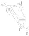
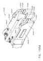
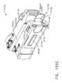
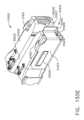
本発明は、外科用器具に関し、また、様々な状況において組織をステープル留めし、切断するために設計された、外科用ステープル留め及び切断器具並びにそれらと共に使用するためのステープルカートリッジに関する。 The present invention relates to surgical instruments and to surgical stapling and severing instruments and staple cartridges for use therewith designed for stapling and severing tissue in a variety of situations.
本明細書に記載する実施形態の様々な特徴は、それらの利点と共に、以下の添付図面と併せて以下の説明によって理解することができる。
複数の図面を通して、対応する参照符号は対応する部分を示す。本明細書に記載される例示は、本発明の様々な実施形態を1つの形態で例示するものであり、かかる例示は、いかなる方法によっても本発明の範囲を限定するものとして解釈されるべきではない。 Corresponding reference characters indicate corresponding parts throughout the drawings. The exemplifications set forth herein are illustrative of various embodiments of the invention in one form and such exemplifications should not be construed as limiting the scope of the invention in any way. do not have.
本願の出願人は、本願と同日に出願された以下の米国特許出願を所有しており、これらは各々、それらの全体が参照により本明細書に組み込まれる。
-米国特許出願、発明の名称「METHODS FOR CONTROLLING A POWERED SURGICAL STAPLER THAT HAS SEPARATE ROTARY CLOSURE AND FIRING SYSTEMS」、代理人整理番号END9020USNP1/180504-1M、
-米国特許出願、発明の名称「STAPLE CARTRIDGE COMPRISING A LOCKOUT KEY CONFIGURED TO LIFT A FIRING MEMBER」、代理人整理番号END9021USNP1/180505-1、
-米国特許出願、発明の名称「SURGICAL STAPLERS WITH ARRANGEMENTS FOR MAINTAINING A FIRING MEMBER THEREOF IN A LOCKED CONFIGURATION UNLESS A COMPATIBLE CARTRIDGE HAS BEEN INSTALLED THEREIN」、代理人整理番号END9021USNP2/180505-2、
-米国特許出願、発明の名称「SURGICAL INSTRUMENT COMPRISING CO-OPERATING LOCKOUT FEATURES」、代理人整理番号第END9021USNP3/180505-3号、
-米国特許出願、発明の名称「SURGICAL STAPLING DEVICES WITH FEATURES FOR BLOCKING ADVANCEMENT OF A CAMMING ASSEMBLY OF AN INCOMPATIBLE CARTRIDGE INSTALLED THEREIN」、代理人整理番号END9021USNP5/180505-5、
-米国特許出願、発明の名称「STAPLING INSTRUMENT COMPRISING A DEACTIVATABLE LOCKOUT」、代理人整理番号END9021USNP6/18505-6、
-米国特許出願、発明の名称「SURGICAL INSTRUMENT COMPRISING A JAW CLOSURE LOCKOUT」、代理人整理番号END9021USNP7/180505-7、
-米国特許出願、発明の名称「SURGICAL STAPLING DEVICES WITH CARTRIDGE COMPATIBLE CLOSURE AND FIRING LOCKOUT ARRANGEMENTS」、代理人整理番号END9021USNP8/180505-8、
-米国特許出願、発明の名称「SURGICAL STAPLE CARTRIDGE WITH FIRING MEMBER DRIVEN CAMMING ASSEMBLY THAT HAS AN ONBOARD TISSUE CUTTING FEATURE」、代理人整理番号END9022USNP1/180508-1、
-米国特許出願、発明の名称「SURGICAL STAPLING DEVICES WITH IMPROVED ROTARY DRIVEN CLOSURE SYSTEMS」、代理人整理番号END9022USNP2/180508-2、
-米国特許出願、発明の名称「SURGICAL STAPLING DEVICES WITH ASYMMETRIC CLOSURE FEATURES」、代理人整理番号END9022USNP3/180508-3、
-米国特許出願、発明の名称「ROTARY DRIVEN FIRING MEMBERS WITH DIFFERENT ANVIL AND CHANNEL ENGAGEMENT FEATURES」、代理人整理番号END9022USNP4/180508-4、及び
-米国特許出願、発明の名称「SURGICAL STAPLING DEVICE WITH SEPARATE ROTARY DRIVEN CLOSURE AND FIRING SYSTEMS AND FIRING MEMBER THAT ENGAGES BOTH JAWS WHILE FIRING」、代理人整理番号END9022USNP5/180508-5。The applicant of this application owns the following US patent applications filed on even date herewith, each of which is hereby incorporated by reference in their entirety.
- U.S. Patent Application entitled "METHODS FOR CONTROLLING A POWERED SURGICAL STAPLER THAT HAS SEPARATE ROTARY CLOSURE AND FIRRING SYSTEMS", Attorney Docket No. END9020USNP1/180504-1M,
- U.S. Patent Application entitled "STAPLE CARTRIDGE COMPRISING A LOCKOUT KEY CONFIGURED TO LIFT A FIRING MEMBER", Attorney Docket No. END9021USNP1/180505-1,
- US patent application entitled "SURGICAL STAPLERS WITH ARRANGEMENTS FOR MAINTAINING A FIRING MEMBER THEREOF IN A LOCKED CONFIGURATION UNLESS A COMPATIBLE CARTRIDGE HAS BEEN INSTAL LED THEREIN", agent reference number END9021USNP2/180505-2,
- US patent application entitled "SURGICAL INSTRUMENT COMPRISING CO-OPERATING LOCKOUT FEATURES", Attorney Docket No. END9021USNP3/180505-3;
- US patent application entitled "SURGICAL STAPLING DEVICES WITH FEATURES FOR BLOCKING ADVANCEMENT OF A CAMTING ASSEMBLY OF AN INCOMPATIBLE CARTRIDGE INSTALLED THEREIN", Attorney Docket No. END9021US NP5/180505-5,
- US patent application entitled "STAPLING INSTRUMENT COMPRISING A DEACTIVATABLE LOCKOUT", Attorney Docket No. END9021USNP6/18505-6,
- US patent application entitled "SURGICAL INSTRUMENT COMPRISING A JAW CLOSURE LOCKOUT", Attorney Docket No. END9021USNP7/180505-7,
- US patent application entitled "SURGICAL STAPLING DEVICES WITH CARTRIDGE COMPATIBLE CLOSURE AND FIRRING LOCKOUT ARRANGEMENTS", Attorney Docket No. END9021USNP8/180505-8,
- U.S. Patent Application entitled "SURGICAL STAPLE CARTRIDGE WITH FIRING MEMBER DRIVEN CAMMING ASSEMBLY THAT HAS AN ONBOARD TISSUE CUTTING FEATURE", Attorney Docket No. END9022USNP1/180508-1,
- US patent application entitled "SURGICAL STAPLING DEVICES WITH IMPROVED ROTARY DRIVEN CLOURE SYSTEMS", Attorney Docket No. END9022USNP2/180508-2,
- US patent application entitled "SURGICAL STAPLING DEVICES WITH ASYMMETRIC CLOSURE FEATURES", Attorney Docket No. END9022USNP3/180508-3,
- U.S. Patent Application entitled "ROTARY DRIVEN FIRRING MEMBERS WITH DIFFERENT ANVIL AND CHANNEL ENGAGEMENT FEATURES", Attorney Docket No. END9022USNP4/180508-4; ICE WITH SEPARATE ROTARY DRIVEN CLOSURE AND FIRING SYSTEMS AND FIRING MEMBER THAT ENGAGES BOTH JAWS WHILE FIRING", Attorney Docket No. END9022USNP5/180508-5.
本願の出願人は、2019年2月19日に出願された以下の米国特許出願を所有しており、これらは各々、それらの全体が参照により本明細書に組み込まれる。
-米国仮特許出願第62/807,310号、発明の名称「METHODS FOR CONTROLLING A POWERED SURGICAL STAPLER THAT HAS SEPARATE ROTARY CLOSURE AND FIRING SYSTEMS」、
-米国仮特許出願第62/807,319号、発明の名称「SURGICAL STAPLING DEVICES WITH IMPROVED LOCKOUT SYSTEMS」、及び
-米国仮特許出願第62/807,309号、発明の名称「SURGICAL STAPLING DEVICES WITH IMPROVED ROTARY DRIVEN CLOSURE SYSTEMS」。The applicant of this application owns the following US patent applications filed on February 19, 2019, each of which is incorporated herein by reference in its entirety.
- U.S. Provisional Patent Application No. 62/807,310, entitled "METHODS FOR CONTROLLING A POWERED SURGICAL STAPLER THAT HAS SEPARATE ROTARY CLOSURE AND FIRRING SYSTEMS",
- U.S. Provisional Patent Application No. 62/807,319, entitled "SURGICAL STAPLING DEVICES WITH IMPROVED LOCKOUT SYSTEMS"; ROTARY DRIVEN CLOSURE SYSTEMS".
本願の出願人は、2018年3月28日に出願された以下の米国仮特許出願を所有しており、これらの各々の全内容は、参照により本明細書に組み込まれる。
-米国仮特許出願第62/649,302号、発明の名称「INTERACTIVE SURGICAL SYSTEMS WITH ENCRYPTED COMMUNICATION CAPABILITIES」、
-米国仮特許出願第62/649,294号、発明の名称「DATA STRIPPING METHOD TO INTERROGATE PATIENT RECORDS AND CREATE ANONYMIZED RECORD」、
-米国仮特許出願第62/649,300号、発明の名称「SURGICAL HUB SITUATIONAL AWARENESS」、
-米国仮特許出願第62/649,309号、発明の名称「SURGICAL HUB SPATIAL AWARENESS TO DETERMINE DEVICES IN OPERATING THEATER」、
-米国仮特許出願第62/649,310号、発明の名称「COMPUTER IMPLEMENTED INTERACTIVE SURGICAL SYSTEMS」、
-米国仮特許出願第62/649,291号、発明の名称「USE OF LASER LIGHT AND RED-GREEN-BLUE COLORATION TO DETERMINE PROPERTIES OF BACK SCATTERED LIGHT」、
-米国仮特許出願第62/649,296号、発明の名称「ADAPTIVE CONTROL PROGRAM UPDATES FOR SURGICAL DEVICES」、
-米国仮特許出願第62/649,333号、発明の名称「CLOUD-BASED MEDICAL ANALYTICS FOR CUSTOMIZATION AND RECOMMENDATIONS TO A USER」、
-米国仮特許出願第62/649,327号、発明の名称「CLOUD-BASED MEDICAL ANALYTICS FOR SECURITY AND AUTHENTICATION TRENDS AND REACTIVE MEASURES」、
-米国仮特許出願第62/649,315号、発明の名称「DATA HANDLING AND PRIORITIZATION IN A CLOUD ANALYTICS NETWORK」、
-米国仮特許出願第62/649,313号、発明の名称「CLOUD INTERFACE FOR COUPLED SURGICAL DEVICES」、
-米国仮特許出願第62/649,320号、発明の名称「DRIVE ARRANGEMENTS FOR ROBOT-ASSISTED SURGICAL PLATFORMS」、
-米国仮特許出願第62/649,307号、発明の名称「AUTOMATIC TOOL ADJUSTMENTS FOR ROBOT-ASSISTED SURGICAL PLATFORMS」、及び
-米国仮特許出願第62/649,323号、発明の名称「SENSING ARRANGEMENTS FOR ROBOT-ASSISTED SURGICAL PLATFORMS」。The applicant of this application owns the following US provisional patent applications filed March 28, 2018, the entire contents of each of which are incorporated herein by reference:
- US Provisional Patent Application No. 62/649,302, entitled "INTERACTIVE SURGICAL SYSTEMS WITH ENCRYPTED COMMUNICATION CAPABILITIES",
- US Provisional Patent Application No. 62/649,294, entitled "DATA STRIPING METHOD TO INTERROGATE PATIENT RECORDS AND CREATE ANONYMIZED RECORD",
- U.S. Provisional Patent Application No. 62/649,300, entitled "SURGICAL HUB SITUATIONAL AWARENESS";
- US Provisional Patent Application No. 62/649,309, entitled "SURGICAL HUB SPATIAL AWARENESS TO DETERMINE DEVICES IN OPERATING THEATER",
- US Provisional Patent Application No. 62/649,310, entitled "COMPUTER IMPLEMENTED INTERACTIVE SURGICAL SYSTEMS",
- U.S. Provisional Patent Application No. 62/649,291 entitled "USE OF LASER LIGHT AND RED-GREEN-BLUE COLORATION TO DETERMINE PROPERTIES OF BACK SCATTERED LIGHT",
- US Provisional Patent Application No. 62/649,296, entitled "ADAPTIVE CONTROL PROGRAM UPDATES FOR SURGICAL DEVICES",
- US Provisional Patent Application No. 62/649,333, entitled "CLOUD-BASED MEDICAL ANALYTICS FOR CUSTOMIZATION AND RECOMMENDATIONS TO A USER",
- US Provisional Patent Application No. 62/649,327, entitled "CLOUD-BASED MEDICAL ANALYTICS FOR SECURITY AND AUTHENTICATION TRENDS AND REACTIVE MEASURES";
- US Provisional Patent Application No. 62/649,315, entitled "DATA HANDLING AND PRIORITIZATION IN A CLOUD ANALYTICS NETWORK",
- US Provisional Patent Application No. 62/649,313, entitled "CLOUD INTERFACE FOR COUPLED SURGICAL DEVICES",
- US Provisional Patent Application No. 62/649,320, entitled "DRIVE ARRANGEMENTS FOR ROBOT-ASSISTED SURGICAL PLATFORMS",
- U.S. Provisional Patent Application No. 62/649,307, entitled "AUTOMATIC TOOL ADJUSTMENTS FOR ROBOT-ASSISTED SURGICAL PLATFORMS," and - U.S. Provisional Patent Application No. 62/649,323, entitled "SENSING ARRANGEMENTS FOR ROB." OT -Assisted Surgical Platforms".
本願の出願人は、2018年3月30日に出願された以下の米国仮特許出願を所有しており、その全体が参照により本明細書に組み込まれる。
-米国仮特許出願第62/650,887号、発明の名称「SURGICAL SYSTEMS WITH OPTIMIZED SENSING CAPABILITIES」。The applicant of this application owns the following US provisional patent application filed March 30, 2018, which is hereby incorporated by reference in its entirety:
- US Provisional Patent Application No. 62/650,887, entitled "SURGICAL SYSTEMS WITH OPTIMIZED SENSING CAPABILITIES".
本願の出願人は、2018年12月4日に出願された以下の米国仮特許出願を所有しており、その全体が参照により本明細書に組み込まれる。
-米国特許出願第16/209,423号、発明の名称「METHOD OF COMPRESSING TISSUE WITHIN A STAPLING DEVICE AND SIMULTANEOUSLY DISPLAYING THE LOCATION OF THE TISSUE WITHIN THE JAWS」。The applicant of this application owns the following US provisional patent application filed December 4, 2018, which is hereby incorporated by reference in its entirety:
- U.S. patent application Ser. .
本願の出願人は、2018年8月20日に出願された以下の米国特許出願を所有しており、これらは各々、それらの全体が参照により本明細書に組み込まれる。
-米国特許出願第16/105,101号、発明の名称「METHOD FOR FABRICATING SURGICAL STAPLER ANVILS」、
-米国特許出願第16/105,183号、発明の名称「REINFORCED DEFORMABLE ANVIL TIP FOR SURGICAL STAPLER ANVIL」、
-米国特許出願第16/105,150号、発明の名称「SURGICAL STAPLER ANVILS WITH STAPLE DIRECTING PROTRUSIONS AND TISSUE STABILITY FEATURES」、
-米国特許出願第16/105,098号、発明の名称「FABRICATING TECHNIQUES FOR SURGICAL STAPLER ANVILS」、
-米国特許出願第16/105,140号、発明の名称「SURGICAL STAPLER ANVILS WITH TISSUE STOP FEATURES CONFIGURED TO AVOID TISSUE PINCH」、
-米国特許出願第16/105,081号、発明の名称「METHOD FOR OPERATING A POWERED ARTICULATABLE SURGICAL INSTRUMENT」、
-米国特許出願第16/105,094号、発明の名称「SURGICAL INSTRUMENTS WITH PROGRESSIVE JAW CLOSURE ARRANGEMENTS」、
-米国特許出願第16/105,097号、発明の名称「POWERED SURGICAL INSTRUMENTS WITH CLUTCHING ARRANGEMENTS TO CONVERT LINEAR DRIVE MOTIONS TO ROTARY DRIVE MOTIONS」、
-米国特許出願第16/105,104号、発明の名称「POWERED ARTICULATABLE SURGICAL INSTRUMENTS WITH CLUTCHING AND LOCKING ARRANGEMENTS FOR LINKING AN ARTICULATION DRIVE SYSTEM TO A FIRING DRIVE SYSTEM」、
-米国特許出願第16/105,119号、発明の名称「ARTICULATABLE MOTOR POWERED SURGICAL INSTRUMENTS WITH DEDICATED ARTICULATION MOTOR ARRANGEMENTS」、
-米国特許出願第16/105160号、発明の名称「SWITCHING ARRANGEMENTS FOR MOTOR POWERED ARTICULATABLE SURGICAL INSTRUMENTS」、及び
-米国意匠特許出願第29/660,252号、発明の名称「SURGICAL STAPLER ANVILS」。The applicant of the present application owns the following US patent applications filed Aug. 20, 2018, each of which is incorporated herein by reference in its entirety.
- US patent application Ser. No. 16/105,101 entitled "METHOD FOR FABRICATING SURGICAL STAPLER ANVILS",
- US patent application Ser. No. 16/105,183, entitled "REINFORCED DEFORMABLE ANVIL TIP FOR SURGICAL STAPLER ANVIL"
- U.S. patent application Ser.
- U.S. patent application Ser.
- U.S. patent application Ser.
- U.S. patent application Ser.
- U.S. patent application Ser.
- U.S. patent application Ser.
- U.S. patent application Ser. G DRIVE SYSTEM",
- U.S. patent application Ser.
- US Patent Application No. 16/105160, entitled "SWITCHING ARRANGEMENTS FOR MOTOR POWERED ARTICULATABLE SURGICAL INSTRUMENTS";
本願の出願人は、以下の米国特許出願及び米国特許を所有しており、これらは各々、それらの全体が参照により本明細書に組み込まれる。
-米国特許出願第15/386,185号、発明の名称「SURGICAL STAPLING INSTRUMENTS AND REPLACEABLE TOOL ASSEMBLIES THEREOF」、現在は米国特許出願公開第2018/0168642号、
-米国特許出願第15/386,230号、発明の名称「ARTICULATABLE SURGICAL STAPLING INSTRUMENTS」、現在は米国特許出願公開第2018/0168649号、
-米国特許出願第15/386,221号、発明の名称「LOCKOUT ARRANGEMENTS FOR SURGICAL END EFFECTORS」、現在は米国特許出願公開第2018/0168646号、
-米国特許出願第15/386,209号、発明の名称「SURGICAL END EFFECTORS AND FIRING MEMBERS THEREOF」、現在は米国特許出願公開第2018/0168645号、
-米国特許出願第15/386,198号、発明の名称「LOCKOUT ARRANGEMENTS FOR SURGICAL END EFFECTORS AND REPLACEABLE TOOL ASSEMBLIES」、現在は米国特許出願公開第2018/0168644号、
-米国特許出願第15/386,240号、発明の名称「SURGICAL END EFFECTORS AND ADAPTABLE FIRING MEMBERS THEREFOR」、現在は米国特許出願公開第2018/0168651号、
-米国特許出願第15/385,939号、発明の名称「STAPLE CARTRIDGES AND ARRANGEMENTS OF STAPLES AND STAPLE CAVITIES THEREIN」、現在は米国特許出願公開第2018/0168629号、
-米国特許出願第15/385,941号、発明の名称「SURGICAL TOOL ASSEMBLIES WITH CLUTCHING ARRANGEMENTS FOR SHIFTING BETWEEN CLOSURE SYSTEMS WITH CLOSURE STROKE REDUCTION FEATURES AND ARTICULATION AND FIRING SYSTEMS」現在は米国特許出願公開第2018/0168630号、
-米国特許出願第15/385,943号、発明の名称「SURGICAL STAPLING INSTRUMENTS AND STAPLE-FORMING ANVILS」、現在は米国特許出願公開第2018/0168631号、
-米国特許出願第15/385,950号、発明の名称「SURGICAL TOOL ASSEMBLIES WITH CLOSURE STROKE REDUCTION FEATURES」、現在は米国特許出願公開第2018/0168635号、
-米国特許出願第15/385,945号、発明の名称「STAPLE CARTRIDGES AND ARRANGEMENTS OF STAPLES AND STAPLE CAVITIES THEREIN」、現在は米国特許出願公開第2018/0168632号、
-米国特許出願第15/385,946号、発明の名称「SURGICAL STAPLING INSTRUMENTS AND STAPLE-FORMING ANVILS」、現在は米国特許出願公開第2018/0168633号、
-米国特許出願第15/385,951号、発明の名称「SURGICAL INSTRUMENTS WITH JAW OPENING FEATURES FOR INCREASING A JAW OPENING DISTANCE」、現在は米国特許出願公開第2018/0168636号、
-米国特許出願第15/385,953号、発明の名称「METHODS FOR STAPLING TISSUE」、現在は米国特許出願公開第2018/0168637号、
-米国特許出願第15/385,954号、発明の名称「FIRING MEMBERS WITH NON-PARALLEL JAW ENGAGEMENT FEATURES FOR SURGICAL END EFFECTORS」、現在は米国特許出願公開第2018/0168638号、
-米国特許出願第15/385,955号、発明の名称「SURGICAL END EFFECTORS WITH EXPANDABLE TISSUE STOP ARRANGEMENTS」、現在は米国特許出願公開第2018/0168639号、
-米国特許出願第15/385,948号、発明の名称「SURGICAL STAPLING INSTRUMENTS AND STAPLE-FORMING ANVILS」、現在は米国特許出願公開第2018/0168584号、
-米国特許出願第15/385,956号、発明の名称「SURGICAL INSTRUMENTS WITH POSITIVE JAW OPENING FEATURES」、現在は米国特許出願公開第2018/0168640号、
-米国特許出願第15/385,958号、発明の名称「SURGICAL INSTRUMENTS WITH LOCKOUT ARRANGEMENTS FOR PREVENTING FIRING SYSTEM ACTUATION UNLESS AN UNSPENT STAPLE CARTRIDGE IS PRESENT」、現在は米国特許出願第2018/0168641号、
-米国特許出願第15/385,947号、発明の名称「STAPLE CARTRIDGES AND ARRANGEMENTS OF STAPLES AND STAPLE CAVITIES THEREIN」、現在は米国特許出願公開第2018/0168634号、
-米国特許出願第15/385,896号、発明の名称「METHOD FOR RESETTING A FUSE OF A SURGICAL INSTRUMENT SHAFT」、現在は米国特許出願公開第2018/0168597号、
-米国特許出願第15/385,898号、発明の名称「STAPLE-FORMING POCKET ARRANGEMENT TO ACCOMMODATE DIFFERENT TYPES OF STAPLES」、現在は米国特許出願公開第2018/0168599号、
-米国特許出願第15/385,899号、発明の名称「SURGICAL INSTRUMENT COMPRISING IMPROVED JAW CONTROL」、現在は米国特許出願公開第2018/0168600号、
-米国特許出願第15/385,901号、発明の名称「STAPLE CARTRIDGE AND STAPLE CARTRIDGE CHANNEL COMPRISING WINDOWS DEFINED THEREIN」、現在は米国特許出願公開第2018/0168602号、
-米国特許出願第15/385,902号、発明の名称「SURGICAL INSTRUMENT COMPRISING A CUTTING MEMBER」、現在は米国特許出願公開第2018/0168603号、
-米国特許出願第15/385,904号、発明の名称「STAPLE FIRING MEMBER COMPRISING A MISSING CARTRIDGE AND/OR SPENT CARTRIDGE LOCKOUT」、現在は米国特許出願公開第2018/0168605号、
-米国特許出願第15/385,905号、発明の名称「FIRING ASSEMBLY COMPRISING A LOCKOUT」、現在は米国特許出願公開第2018/0168606号、
-米国特許出願第15/385,907号、発明の名称「SURGICAL INSTRUMENT SYSTEM COMPRISING AN END EFFECTOR LOCKOUT AND A FIRING ASSEMBLY LOCKOUT」、現在は米国特許出願公開第2018/0168608号、
-米国特許出願第15/385,908号、発明の名称「FIRING ASSEMBLY COMPRISING A FUSE」、現在は米国特許出願公開第2018/0168609号、
-米国特許出願第15/385,909号、発明の名称「FIRING ASSEMBLY COMPRISING A MULTIPLE FAILED-STATE FUSE」、現在は米国特許出願公開第2018/0168610号、
-米国特許出願第15/385,920号、発明の名称「STAPLE-FORMING POCKET ARRANGEMENTS」、現在は米国特許出願公開第2018/0168620号、
-米国特許出願第15/385,913号、発明の名称「ANVIL ARRANGEMENTS FOR SURGICAL STAPLERS」、現在は米国特許出願公開第2018/0168614号、
-米国特許出願第15/385,914号、発明の名称「METHOD OF DEFORMING STAPLES FROM TWO DIFFERENT TYPES OF STAPLE CARTRIDGES WITH THE SAME SURGICAL STAPLING INSTRUMENT」、現在は米国特許出願公開第2018/0168615号、
-米国特許出願第15/385,893号、発明の名称「BILATERALLY ASYMMETRIC STAPLE-FORMING POCKET PAIRS」、現在は米国特許出願公開第2018/0168594号、
-米国特許出願第15/385,929号、発明の名称「CLOSURE MEMBERS WITH CAM SURFACE ARRANGEMENTS FOR SURGICAL INSTRUMENTS WITH SEPARATE AND DISTINCT CLOSURE AND FIRING SYSTEMS」、現在は米国特許出願公開第2018/0168626号、
-米国特許出願第15/385,911号、発明の名称「SURGICAL STAPLERS WITH INDEPENDENTLY ACTUATABLE CLOSING AND FIRING SYSTEMS」、現在は米国特許出願公開第2018/0168612号、
-米国特許出願第15/385,927号、発明の名称「SURGICAL STAPLING INSTRUMENTS WITH SMART STAPLE CARTRIDGES」、現在は米国特許出願公開第2018/0168625号、
-米国特許出願第15/385,917号、名称「STAPLE CARTRIDGE COMPRISING STAPLES WITH DIFFERENT CLAMPING BREADTHS」、現在は米国特許出願公開第2018/0168617号、
-米国特許出願第15/385,900号、発明の名称「STAPLE-FORMING POCKET ARRANGEMENTS COMPRISING PRIMARY SIDEWALLS AND POCKET SIDEWALLS」、現在は米国特許出願公開第2018/0168601号、
-米国特許出願第15/385,931号、発明の名称「NO-CARTRIDGE AND SPENT CARTRIDGE LOCKOUT ARRANGEMENTS FOR SURGICAL STAPLERS」、現在は米国特許出願公開第2018/0168627号、
-米国特許出願第15/385,915号、発明の名称「FIRING MEMBER PIN ANGLE」、現在は米国特許出願公開第2018/0168616号、
-米国特許出願第15/385,897号、発明の名称「STAPLE-FORMING POCKET ARRANGEMENTS COMPRISING ZONED FORMING SURFACE GROOVES」、現在は米国特許出願公開第2018/0168598号、
-米国特許出願第15/385,922号、発明の名称「SURGICAL INSTRUMENT WITH MULTIPLE FAILURE RESPONSE MODES」、現在は米国特許出願公開第2018/0168622号、
-米国特許出願第15/385,924号、発明の名称「SURGICAL INSTRUMENT WITH PRIMARY AND SAFETY PROCESSORS」、現在は米国特許出願公開第2018/0168624号、
-米国特許出願第15/385,910号、発明の名称「ANVIL HAVING A KNIFE SLOT WIDTH」、現在は米国特許出願公開第2018/0168611号、
-米国特許出願第15/385,903号、発明の名称「CLOSURE MEMBER ARRANGEMENTS FOR SURGICAL INSTRUMENTS」、現在は米国特許出願公開第2018/0168604号、
-米国特許出願第15/385,906号、発明の名称「FIRING MEMBER PIN CONFIGURATIONS」、現在は米国特許出願公開第2018/0168607号、
-米国特許出願第15/386,188号、発明の名称「STEPPED STAPLE CARTRIDGE WITH ASYMMETRICAL STAPLES」、現在は米国特許出願公開第2018/0168585号、
-米国特許出願第15/386,192号、発明の名称「STEPPED STAPLE CARTRIDGE WITH TISSUE RETENTION AND GAP SETTING FEATURES」、現在は米国特許出願公開第2018/0168643号、
-米国特許出願第15/386,206号、発明の名称「STAPLE CARTRIDGE WITH DEFORMABLE DRIVER RETENTION FEATURES」、現在は米国特許出願公開第2018/0168586号、
-米国特許出願第15/386,226号、発明の名称「DURABILITY FEATURES FOR END EFFECTORS AND FIRING ASSEMBLIES OF SURGICAL STAPLING INSTRUMENTS」、現在は米国特許出願公開第2018/0168648号、
-米国特許出願第15/386,222号、発明の名称「SURGICAL STAPLING INSTRUMENTS HAVING END EFFECTORS WITH POSITIVE OPENING FEATURES」、現在は米国特許出願公開第2018/0168647号、
-米国特許出願第15/386,236号、発明の名称「CONNECTION PORTIONS FOR DEPOSABLE LOADING UNITS FOR SURGICAL STAPLING INSTRUMENTS」、現在は米国特許出願公開第2018/0168650号、
-米国特許出願第15/385,887号、発明の名称「METHOD FOR ATTACHING A SHAFT ASSEMBLY TO A SURGICAL INSTRUMENT AND,ALTERNATIVELY,TO A SURGICAL ROBOT」、現在は米国特許出願公開第2018/0168589号、
-米国特許出願第15/385,889号、発明の名称「SHAFT ASSEMBLY COMPRISING A MANUALLY-OPERABLE RETRACTION SYSTEM FOR USE WITH A MOTORIZED SURGICAL INSTRUMENT SYSTEM」、現在は米国特許出願公開第2018/0168590号、
-米国特許出願第15/385,890号、発明の名称「SHAFT ASSEMBLY COMPRISING SEPARATELY ACTUATABLE AND RETRACTABLE SYSTEMS」、現在は米国特許出願公開第2018/0168591号、
-米国特許出願第15/385,891号、発明の名称「SHAFT ASSEMBLY COMPRISING A CLUTCH CONFIGURED TO ADAPT THE OUTPUT OF A ROTARY FIRING MEMBER TO TWO DIFFERENT SYSTEMS」、現在は米国特許出願公開第2018/0168592号、
-米国特許出願第15/385,892号、発明の名称「SURGICAL SYSTEM COMPRISING A FIRING MEMBER ROTATABLE INTO AN ARTICULATION STATE TO ARTICULATE AN END EFFECTOR OF THE SURGICAL SYSTEM」、現在は米国特許出願公開第2018/0168593号、
-米国特許出願第15/385,894号、発明の名称「SHAFT ASSEMBLY COMPRISING A LOCKOUT」、現在は米国特許出願公開第2018/0168595号、
-米国特許出願第15/385,895号、名称「SHAFT ASSEMBLY COMPRISING FIRST AND SECOND ARTICULATION LOCKOUTS」、現在は米国特許出願公開第2018/0168596号、
-米国特許出願第15/385,916号、発明の名称「SURGICAL STAPLING SYSTEMS」、現在は米国特許出願公開第2018/0168575号、
-米国特許出願第15/385,918号、発明の名称「SURGICAL STAPLING SYSTEMS」、現在は米国特許出願公開第2018/0168618号、
-米国特許出願第15/385,919号、発明の名称「SURGICAL STAPLING SYSTEMS」、現在は米国特許出願公開第2018/0168619号、
-米国特許出願第15/385,921号、発明の名称「SURGICAL STAPLE CARTRIDGE WITH MOVABLE CAMMING MEMBER CONFIGURED TO DISENGAGE FIRING MEMBER LOCKOUT FEATURES」、現在は米国特許出願公開第2018/0168621号、
-米国特許出願第15/385,923号、発明の名称「SURGICAL STAPLING SYSTEMS」、現在は米国特許出願公開第2018/0168623号、
-米国特許出願第15/385,925号、発明の名称「JAW ACTUATED LOCK ARRANGEMENTS FOR PREVENTING ADVANCEMENT OF A FIRING MEMBER IN A SURGICAL END EFFECTOR UNLESS AN UNFIRED CARTRIDGE IS INSTALLED IN THE END EFFECTOR」、現在は米国特許出願公開第2018/0168576号、
-米国特許出願第15/385,926号、発明の名称「AXIALLY MOVABLE CLOSURE SYSTEM ARRANGEMENTS FOR APPLYING CLOSURE MOTIONS TO JAWS OF SURGICAL INSTRUMENTS」、現在は米国特許出願公開第2018/0168577号、
-米国特許出願第15/385,928号、発明の名称「PROTECTIVE COVER ARRANGEMENTS FOR A JOINT INTERFACE BETWEEN A MOVABLE JAW AND ACTUATOR SHAFT OF A SURGICAL INSTRUMENT」、現在は米国特許出願公開第2018/0168578号、
-米国特許出願第15/385,930号、発明の名称「SURGICAL END EFFECTOR WITH TWO SEPARATE COOPERATING OPENING FEATURES FOR OPENING AND CLOSING END EFFECTOR JAWS」、現在は米国特許出願公開第2018/0168579号、
-米国特許出願第15/385,932号、発明の名称「ARTICULATABLE SURGICAL END EFFECTOR WITH ASYMMETRIC SHAFT ARRANGEMENT」、現在は米国特許出願公開第2018/0168628号、
-米国特許出願第15/385,933号、発明の名称「ARTICULATABLE SURGICAL INSTRUMENT WITH INDEPENDENT PIVOTABLE LINKAGE DISTAL OF AN ARTICULATION LOCK」、現在は米国特許出願公開第2018/0168580号、
-米国特許出願第15/385,934号、発明の名称「ARTICULATION LOCK ARRANGEMENTS FOR LOCKING AN END EFFECTOR IN AN ARTICULATED POSITION IN RESPONSE TO ACTUATION OF A JAW CLOSURE SYSTEM」、現在は米国特許出願公開第2018/0168581号、
-米国特許出願第15/385,935号、発明の名称「LATERALLY ACTUATABLE ARTICULATION LOCK ARRANGEMENTS FOR LOCKING AN END EFFECTOR OF A SURGICAL INSTRUMENT IN AN ARTICULATED CONFIGURATION」、現在は米国特許出願公開第2018/0168582号、
-米国特許出願第15/385,936号、発明の名称「ARTICULATABLE SURGICAL INSTRUMENTS WITH ARTICULATION STROKE AMPLIFICATION FEATURES」、現在は米国特許出願公開第2018/0168583号、
-米国特許出願第14/318,996号、発明の名称「FASTENER CARTRIDGES INCLUDING EXTENSIONS HAVING DIFFERENT CONFIGURATIONS」、現在は米国特許出願公開第2015/0297228号、
-米国特許出願第14/319,006号、発明の名称「FASTENER CARTRIDGE COMPRISING FASTENER CAVITIES INCLUDING FASTENER CONTROL FEATURES」、現在は米国特許第10,010,324号、
-米国特許出願第14/318,991号、発明の名称「SURGICAL FASTENER CARTRIDGES WITH DRIVER STABILIZING ARRANGEMENTS」、現在は米国特許第9,833,241号、
-米国特許出願第14/319,004号、発明の名称「SURGICAL END EFFECTORS WITH FIRING ELEMENT MONITORING ARRANGEMENTS」、現在は米国特許第9,844,369号、
-米国特許出願第14/319,008号、発明の名称「FASTENER CARTRIDGE COMPRISING NON-UNIFORM FASTENERS」、現在は米国特許出願公開第2015/0297232号、
-米国特許出願第14/318,997号、発明の名称「FASTENER CARTRIDGE COMPRISING DEPLOYABLE TISSUE ENGAGING MEMBERS」、現在は米国特許出願公開第2015/0297229号、
-米国特許出願第14/319,002号、発明の名称「FASTENER CARTRIDGE COMPRISING TISSUE CONTROL FEATURES」、現在は米国特許第9,877,721号、
-米国特許出願第14/319,013号、発明の名称「FASTENER CARTRIDGE ASSEMBLIES AND STAPLE RETAINER COVER ARRANGEMENTS」、現在は米国特許出願公開第2015/0297233号、及び
-米国特許出願第14/319,016号、発明の名称「FASTENER CARTRIDGE INCLUDING A LAYER ATTACHED THERETO」、現在は米国特許出願公開第2015/0297235号。The applicant of the present application owns the following US patent applications and US patents, each of which is incorporated herein by reference in its entirety.
- U.S. patent application Ser.
- U.S. patent application Ser.
- U.S. patent application Ser.
- U.S. patent application Ser.
- U.S. patent application Ser.
- U.S. patent application Ser.
- U.S. patent application Ser.
- U.S. patent application Ser. AND ARTICULATION AND FIRING SYSTEMS, now U.S. Patent Application Publication No. 2018/0168630;
- U.S. patent application Ser.
- U.S. patent application Ser.
- U.S. patent application Ser.
- U.S. patent application Ser.
- U.S. patent application Ser.
- U.S. patent application Ser.
- U.S. patent application Ser.
- U.S. patent application Ser.
- U.S. patent application Ser.
- U.S. patent application Ser.
- U.S. patent application Ser. is U.S. Patent Application No. 2018/0168641;
- U.S. patent application Ser.
- U.S. patent application Ser.
- U.S. patent application Ser.
- U.S. patent application Ser.
- U.S. patent application Ser.
- U.S. patent application Ser.
- U.S. patent application Ser.
- U.S. patent application Ser.
- U.S. patent application Ser.
- U.S. patent application Ser.
- U.S. patent application Ser.
- U.S. patent application Ser.
- U.S. patent application Ser.
- U.S. patent application Ser. /0168615,
- U.S. patent application Ser.
- U.S. patent application Ser. 018/0168626,
- U.S. patent application Ser.
- U.S. patent application Ser.
- U.S. patent application Ser.
- U.S. patent application Ser.
- U.S. patent application Ser.
- US patent application Ser.
- U.S. patent application Ser.
- U.S. patent application Ser.
- U.S. patent application Ser.
- U.S. patent application Ser.
- U.S. patent application Ser.
- U.S. patent application Ser.
- U.S. patent application Ser.
- U.S. patent application Ser.
- U.S. patent application Ser.
- U.S. patent application Ser.
- U.S. patent application Ser.
- U.S. patent application Ser.
- U.S. patent application Ser. No. 9,
- U.S. patent application Ser. /0168590,
- U.S. patent application Ser.
- U.S. patent application Ser. 2018/0168592,
- U.S. patent application Ser. EM, now U.S. Patent Application Publication No. 2018/0168593;
- U.S. patent application Ser.
- U.S. patent application Ser.
- U.S. patent application Ser.
- U.S. patent application Ser.
- U.S. patent application Ser.
- U.S. patent application Ser. 8621,
- US patent application Ser.
- U.S. patent application Ser. TRIDGE IS INSTALLED IN THE END EFFECTOR, now a published US patent application 2018/0168576,
- U.S. patent application Ser. No. 77,
- U.S. patent application Ser. 018/0168578,
- U.S. patent application Ser. 8/0168579,
- U.S. patent application Ser.
- U.S. patent application Ser.
- U.S. patent application Ser. YSTEM”, now U.S. Patent Application Publication No. 2018/0168581 ,
- U.S. patent application Ser. URATION, now U.S. Patent Application Publication No. 2018/0168582;
- U.S. patent application Ser.
- U.S. patent application Ser.
- U.S. patent application Ser.
- U.S. patent application Ser.
- U.S. patent application Ser.
- U.S. patent application Ser.
- U.S. patent application Ser.
- U.S. patent application Ser.
- US Patent Application No. 14/319,013, entitled "FASTENER CARTRIDGE ASSEMBLIES AND STAPLE RETAINER COVER ARRANGEMENTS", now US Patent Application Publication No. 2015/0297233, and - US Patent Application No. 14/319,016. , entitled "FASTENER CARTRIDGE INCLUDING A LAYER ATTACHED THERETO", now U.S. Patent Application Publication No. 2015/0297235.
本願の出願人は、2016年6月24日に出願された以下の米国特許出願を所有しており、これらはそれぞれの内容全体が参照により本明細書に組み込まれる。
-米国特許出願第15/191,775号、発明の名称「STAPLE CARTRIDGE COMPRISING WIRE STAPLES AND STAMPED STAPLES」、現在は米国特許出願公開第2017/0367695号、
-米国特許出願第15/191,807号、発明の名称「STAPLING SYSTEM FOR USE WITH WIRE STAPLES AND STAMPED STAPLES」、現在は米国特許出願公開第2017/0367696号、
-米国特許出願第15/191,834号、発明の名称「STAMPED STAPLES AND STAPLE CARTRIDGES USING THE SAME」、現在は米国特許出願公開第2017/0367699号、
-米国特許出願第15/191,788号、発明の名称「STAPLE CARTRIDGE COMPRISING OVERDRIVEN STAPLES」、現在は米国特許出願公開第2017/0367698号、及び
-米国特許出願第15/191,818号、発明の名称「STAPLE CARTRIDGE COMPRISING OFFSET LONGITUDINAL STAPLE ROWS」、現在は米国特許出願公開第2017/0367697号。The applicant of the present application owns the following US patent applications filed June 24, 2016, each of which is hereby incorporated by reference in its entirety:
- U.S. patent application Ser.
- U.S. patent application Ser.
- U.S. patent application Ser.
- U.S. patent application Ser. Named "STAPLE CARTRIDGE COMPRISING OFFSET LONGITUDINAL STAPLE ROWS", now U.S. Patent Application Publication No. 2017/0367697.
本願の出願人は、2016年6月24日に出願された以下の米国特許出願を所有しており、これらはそれぞれの内容全体が参照により本明細書に組み込まれる。
-米国意匠特許出願第29/569,218号、発明の名称「SURGICAL FASTENER」、現在は米国意匠特許第D826,405号、
-米国意匠特許出願第29/569,227号、発明の名称「SURGICAL FASTENER」、現在は米国意匠特許第D822,206号、
-米国意匠特許出願第29/569,259号、発明の名称「SURGICAL FASTENER CARTRIDGE」、及び
-米国意匠特許出願第29/569,264号、発明の名称「SURGICAL FASTENER CARTRIDGE」。The applicant of the present application owns the following US patent applications filed June 24, 2016, each of which is hereby incorporated by reference in its entirety:
- US Design Patent Application No. 29/569,218, entitled "SURGICAL FASTENER", now US Design Patent No. D826,405;
- US Design Patent Application No. 29/569,227, entitled "SURGICAL FASTENER", now US Design Patent No. D822,206;
- US Design Patent Application No. 29/569,259, entitled "SURGICAL FASTENER CARTRIDGE," and - US Design Patent Application No. 29/569,264, entitled "SURGICAL FASTENER CARTRIDGE."
本願の出願人は、2016年4月1日に出願された以下の特許出願を所有しており、これらはそれぞれの内容全体が参照により本明細書に組み込まれる。
-米国特許出願第15/089,325号、発明の名称「METHOD FOR OPERATING A SURGICAL STAPLING SYSTEM」、現在は米国特許出願公開第2017/0281171号、
-米国特許出願第15/089,321号、発明の名称「MODULAR SURGICAL STAPLING SYSTEM COMPRISING A DISPLAY」、現在は米国特許出願公開第2017/0281163号、
-米国特許出願第15/089,326号、発明の名称「SURGICAL STAPLING SYSTEM COMPRISING A DISPLAY INCLUDING A RE-ORIENTABLE DISPLAY FIELD」、現在は米国特許出願公開第2017/0281172号、
-米国特許出願第15/089,263号、名称「SURGICAL INSTRUMENT HANDLE ASSEMBLY WITH RECONFIGURABLE GRIP PORTION」、現在は米国特許出願公開第2017/0281165号、
-米国特許出願第15/089,262号、発明の名称「ROTARY POWERED SURGICAL INSTRUMENT WITH MANUALLY ACTUATABLE BAILOUT SYSTEM」、現在は米国特許出願公開第2017/0281161号、
-米国特許出願第15/089,277号、発明の名称「SURGICAL CUTTING AND STAPLING END EFFECTOR WITH ANVIL CONCENTRIC DRIVE MEMBER」、現在は米国特許出願公開第2017/0281166号、
-米国特許出願第15/089,296号、発明の名称「INTERCHANGEABLE SURGICAL TOOL ASSEMBLY WITH A SURGICAL END EFFECTOR THAT IS SELECTIVELY ROTATABLE ABOUT A SHAFT AXIS」、現在は米国特許出願公開第2017/0281168号、
-米国特許出願第15/089,258号、発明の名称「SURGICAL STAPLING SYSTEM COMPRISING A SHIFTABLE TRANSMISSION」、現在は米国特許出願公開第2017/0281178号、
-米国特許出願第15/089,278号、発明の名称「SURGICAL STAPLING SYSTEM CONFIGURED TO PROVIDE SELECTIVE CUTTING OF TISSUE」、現在は米国特許出願公開第2017/0281162号、
-米国特許出願第15/089,284号、発明の名称「SURGICAL STAPLING SYSTEM COMPRISING A CONTOURABLE SHAFT」、現在は米国特許出願公開第2017/0281186号、
-米国特許出願第15/089,295号、発明の名称「SURGICAL STAPLING SYSTEM COMPRISING A TISSUE COMPRESSION LOCKOUT」、現在は米国特許出願公開第2017/0281187号、
-米国特許出願第15/089,300号、発明の名称「SURGICAL STAPLING SYSTEM COMPRISING AN UNCLAMPING LOCKOUT」、現在は米国特許出願公開第2017/0281179号、
-米国特許出願第15/089,196号、発明の名称「SURGICAL STAPLING SYSTEM COMPRISING A JAW CLOSURE LOCKOUT」、現在は米国特許出願公開第2017/0281183号、
-米国特許出願第15/089,203号、発明の名称「SURGICAL STAPLING SYSTEM COMPRISING A JAW ATTACHMENT LOCKOUT」、現在は米国特許出願公開第2017/0281184号、
-米国特許出願第15/089,210号、発明の名称「SURGICAL STAPLING SYSTEM COMPRISING A SPENT CARTRIDGE LOCKOUT」、現在は米国特許出願公開第2017/0281185号、
-米国特許出願第15/089,324号、発明の名称「SURGICAL INSTRUMENT COMPRISING A SHIFTING MECHANISM」、現在は、米国特許出願公開第2017/0281170号、
-米国特許出願第15/089,335号、発明の名称「SURGICAL STAPLING INSTRUMENT COMPRISING MULTIPLE LOCKOUTS」、現在は米国特許出願公開第2017/0281155号、
-米国特許出願第15/089,339号、発明の名称「SURGICAL STAPLING INSTRUMENT」、現在は米国特許出願公開第2017/0281173号、
-米国特許出願第15/089,253号、発明の名称「SURGICAL STAPLING SYSTEM CONFIGURED TO APPLY ANNULAR ROWS OF STAPLES HAVING DIFFERENT HEIGHTS」、現在は米国特許出願公開第2017/0281177号、
-米国特許出願第15/089,304号、発明の名称「SURGICAL STAPLING SYSTEM COMPRISING A GROOVED FORMING POCKET」、現在は米国特許出願公開第2017/0281188号、
-米国特許出願第15/089,331号、発明の名称「ANVIL MODIFICATION MEMBERS FOR SURGICAL STAPLERS」、現在は米国特許出願公開第2017/0281180号、
-米国特許出願第15/089,336号、発明の名称「STAPLE CARTRIDGES WITH ATRAUMATIC FEATURES」、現在は米国特許出願公開第2017/0281164号、
-米国特許出願第15/089,312号、名称「CIRCULAR STAPLING SYSTEM COMPRISING AN INCISABLE TISSUE SUPPORT」、現在は米国特許出願公開第2017/0281189号、
-米国特許出願第15/089,309号、発明の名称「CIRCULAR STAPLING SYSTEM COMPRISING ROTARY FIRING SYSTEM」、現在は米国特許出願公開第2017/0281169号、及び
-米国特許出願第15/089,349号、発明の名称「CIRCULAR STAPLING SYSTEM COMPRISING LOAD CONTROL」、現在は米国特許出願公開第2017/0281174号。The applicant of the present application owns the following patent applications filed on April 1, 2016, the entire contents of each of which are incorporated herein by reference:
- U.S. patent application Ser.
- U.S. Patent Application No. 15/089,321, entitled "MODULAR SURGICAL STAPLING SYSTEM COMPRISING A DISPLAY", now U.S. Patent Application Publication No. 2017/0281163,
- U.S. patent application Ser.
- US patent application Ser.
- U.S. patent application Ser.
- U.S. patent application Ser.
- U.S. patent application Ser. Application Publication No. 2017/0281168,
- U.S. patent application Ser.
- U.S. patent application Ser.
- U.S. patent application Ser.
- U.S. patent application Ser.
- U.S. patent application Ser.
- U.S. patent application Ser.
- U.S. patent application Ser.
- U.S. patent application Ser.
- U.S. patent application Ser.
- U.S. patent application Ser.
- U.S. patent application Ser.
- U.S. patent application Ser.
- U.S. patent application Ser.
- U.S. patent application Ser.
- U.S. patent application Ser.
- U.S. Patent Application No. 15/089,312 entitled "CIRCULAR STAPLING SYSTEM COMPRISING AN INCISABLE TISSUE SUPPORT", now U.S. Patent Application Publication No. 2017/0281189;
- US Patent Application No. 15/089,309, entitled "CIRCULAR STAPLING SYSTEM COMPRISING ROTARY FIRING SYSTEM", now US Patent Application Publication No. 2017/0281169, and - US Patent Application No. 15/089,349, Title of Invention "CIRCULAR STAPLING SYSTEM COMPRISING LOAD CONTROL", now U.S. Patent Application Publication No. 2017/0281174.
本願の出願人はまた、2015年12月31日に出願された以下に特定する米国特許出願を所有しており、これらはそれぞれの内容全体が参照により本明細書に組み込まれる。
-米国特許出願第14/984,488号、発明の名称「MECHANISMS FOR COMPENSATING FOR BATTERY PACK FAILURE IN POWERED SURGICAL INSTRUMENTS」、現在は米国特許出願公開第2017/0189018号、
-米国特許出願第14/984,525号、発明の名称「MECHANISMS FOR COMPENSATING FOR DRIVETRAIN FAILURE IN POWERED SURGICAL INSTRUMENTS」、現在は米国特許出願公開第2017/0189019号、及び
-米国特許出願第14/984,552号、発明の名称「SURGICAL INSTRUMENTS WITH SEPARABLE MOTORS AND MOTOR CONTROL CIRCUITS」、現在は米国特許出願公開第2017/0189020号。The applicant of the present application also owns the following identified US patent applications filed December 31, 2015, each of which is hereby incorporated by reference in its entirety.
- U.S. patent application Ser.
- U.S. patent application Ser. 552, entitled "SURGICAL INSTRUMENTS WITH SEPARABLE MOTORS AND MOTOR CONTROL CIRCUITS," now U.S. Patent Application Publication No. 2017/0189020.
本願の出願人はまた、2016年2月9日に出願された以下に特定する米国特許出願を所有しており、これらはそれぞれの内容全体が参照により本明細書に組み込まれる。
-米国特許出願第15/019,220号、発明の名称「SURGICAL INSTRUMENT WITH ARTICULATING AND AXIALLY TRANSLATABLE END EFFECTOR」、現在は米国特許出願公開第2017/0224333号、
-米国特許出願第15/019,228号、発明の名称「SURGICAL INSTRUMENTS WITH MULTIPLE LINK ARTICULATION ARRANGEMENTS」、現在は、米国特許出願公開第2017/0224342号、
-米国特許出願第15/019,196号、名称「SURGICAL INSTRUMENT ARTICULATION MECHANISM WITH SLOTTED SECONDARY CONSTRAINT」、現在は米国特許出願公開第2017/0224330号、
-米国特許出願第15/019,206号、発明の名称「SURGICAL INSTRUMENTS WITH AN END EFFECTOR THAT IS HIGHLY ARTICULATABLE RELATIVE TO AN ELONGATE SHAFT ASSEMBLY」、現在は米国特許出願公開第2017/0224331号、
-米国特許出願第15/019,215号、発明の名称「SURGICAL INSTRUMENTS WITH NON-SYMMETRICAL ARTICULATION ARRANGEMENTS」、現在は、米国特許出願公開第2017/0224332号、
-米国特許出願第15/019,227号、名称「ARTICULATABLE SURGICAL INSTRUMENTS WITH SINGLE ARTICULATION LINK ARRANGEMENTS」、現在は米国特許出願公開第2017/0224334号、
-米国特許出願第15/019,235号、発明の名称「SURGICAL INSTRUMENTS WITH TENSIONING ARRANGEMENTS FOR CABLE DRIVEN ARTICULATION SYSTEMS」、現在は米国特許出願公開第2017/0224336号、
-米国特許出願第15/019,230号、発明の名称「ARTICULATABLE SURGICAL INSTRUMENTS WITH OFF-AXIS FIRING BEAM ARRANGEMENTS」、現在は米国特許出願公開第2017/0224335号、及び
-米国特許出願第15/019,245号、発明の名称「SURGICAL INSTRUMENTS WITH CLOSURE STROKE REDUCTION ARRANGEMENTS」、現在は米国特許出願公開第2017/0224343号。The applicant of the present application also owns the following identified US patent applications filed February 9, 2016, each of which is hereby incorporated by reference in its entirety.
- U.S. patent application Ser.
- U.S. patent application Ser.
- US patent application Ser.
- U.S. patent application Ser. 4331,
- U.S. patent application Ser.
- US patent application Ser.
- U.S. patent application Ser.
- U.S. Patent Application No. 15/019,230, entitled "ARTICULATABLE SURGICAL INSTRUMENTS WITH OFF-AXIS FIRING BEAM ARRANGEMENTS," now U.S. Patent Application Publication No. 2017/0224335; 245, entitled "SURGICAL INSTRUMENTS WITH CLOSURE STROKE REDUCTION ARRANGEMENTS," now U.S. Patent Application Publication No. 2017/0224343.
本願の出願人はまた、2016年2月12日に出願された以下に特定する米国特許出願を所有しており、これらはそれぞれの内容全体が参照により本明細書に組み込まれる。
-米国特許出願第15/043,254号、発明の名称「MECHANISMS FOR COMPENSATING FOR DRIVETRAIN FAILURE IN POWERED SURGICAL INSTRUMENTS」、現在は米国特許出願公開第2017/0231623号、
-米国特許出願第15/043,259号、発明の名称「MECHANISMS FOR COMPENSATING FOR DRIVETRAIN FAILURE IN POWERED SURGICAL INSTRUMENTS」、現在は米国特許出願公開第2017/0231626号、
-米国特許出願第15/043,275号、発明の名称「MECHANISMS FOR COMPENSATING FOR DRIVETRAIN FAILURE IN POWERED SURGICAL INSTRUMENTS」、現在は米国特許出願公開第2017/0231627号、及び
-米国特許出願第15/043,289号、発明の名称「MECHANISMS FOR COMPENSATING FOR DRIVETRAIN FAILURE IN POWERED SURGICAL INSTRUMENTS」、現在は米国特許出願公開第2017/0231628号。The applicant of the present application also owns the following identified US patent applications filed February 12, 2016, each of which is hereby incorporated by reference in its entirety.
- U.S. patent application Ser.
- U.S. patent application Ser.
- U.S. patent application Ser. 289, entitled "MECHANISMS FOR COMPENSATING FOR DRIVE TRAIN FAILURE IN POWERED SURGICAL INSTRUMENTS," now U.S. Patent Application Publication No. 2017/0231628.
本願の出願人は、2015年6月18日に出願された以下の特許出願を所有しており、これらはそれぞれの内容全体が参照により本明細書に組み込まれる。
-米国特許出願第14/742,925号、発明の名称「SURGICAL END EFFECTORS WITH POSITIVE JAW OPENING ARRANGEMENTS」、現在は、米国特許出願公開第2016/0367256号、
-米国特許出願第14/742,941号、発明の名称「SURGICAL END EFFECTORS WITH DUAL CAM ACTUATED JAW CLOSING FEATURES」、現在は米国特許第10,052,102号、
-米国特許出願第14/742,914号、発明の名称「MOVABLE FIRING BEAM SUPPORT ARRANGEMENTS FOR ARTICULATABLE SURGICAL INSTRUMENTS」、現在は米国特許出願公開第2016/0367255号、
-米国特許出願第14/742,900号、発明の名称「ARTICULATABLE SURGICAL INSTRUMENTS WITH COMPOSITE FIRING BEAM STRUCTURES WITH CENTER FIRING SUPPORT MEMBER FOR ARTICULATION SUPPORT」、現在は米国特許出願公開第2016/0367254号、
-米国特許出願第14/742,885号、発明の名称「DUAL ARTICULATION DRIVE SYSTEM ARRANGEMENTS FOR ARTICULATABLE SURGICAL INSTRUMENTS」、現在は米国特許出願公開第2016/0367246号、及び
-米国特許出願第14/742,876号、発明の名称「PUSH/PULL ARTICULATION DRIVE SYSTEMS FOR ARTICULATABLE SURGICAL INSTRUMENTS」、現在は米国特許第10,178,992号。The applicant of the present application owns the following patent applications filed Jun. 18, 2015, each of which is hereby incorporated by reference in its entirety.
- U.S. patent application Ser.
- U.S. patent application Ser.
- U.S. patent application Ser.
- U.S. patent application Ser. U.S. Patent Application Publication No. 2016/0367254,
- U.S. patent application Ser. No., entitled "PUSH/PULL ARTICULATION DRIVE SYSTEMS FOR ARTICULATABLE SURGICAL INSTRUMENTS", now U.S. Pat. No. 10,178,992.
本願の出願人は、2015年3月6日に出願された以下の特許出願を所有しており、これらはそれぞれの内容全体が参照により本明細書に組み込まれる。
-米国特許出願第14/640,746号、発明の名称「POWERED SURGICAL INSTRUMENT」、現在は米国特許第9,808,246号、
-米国特許出願第14/640,795号、発明の名称「MULTIPLE LEVEL THRESHOLDS TO MODIFY OPERATION OF POWERED SURGICAL INSTRUMENTS」、現在は米国特許出願公開第2016/02561185号、
-米国特許出願第14/640,832号、発明の名称「ADAPTIVE TISSUE COMPRESSION TECHNIQUES TO ADJUST CLOSURE RATES FOR MULTIPLE TISSUE TYPES」、現在は米国特許出願公開第2016/0256154号、
-米国特許出願第14/640,935号、発明の名称「OVERLAID MULTI SENSOR RADIO FREQUENCY (RF) ELECTRODE SYSTEM TO MEASURE TISSUE COMPRESSION」、現在は米国特許出願公開第2016/0256071号、
-米国特許出願第14/640,831号、発明の名称「MONITORING SPEED CONTROL AND PRECISION INCREMENTING OF MOTOR FOR POWERED SURGICAL INSTRUMENTS」、現在は米国特許第9,895,148号、
-米国特許出願第14/640,859号、発明の名称「TIME DEPENDENT EVALUATION OF SENSOR DATA TO DETERMINE STABILITY,CREEP,AND VISCOELASTIC ELEMENTS OF MEASURES」、現在は米国特許第10,052,044号、
-米国特許出願第14/640,817号、発明の名称「INTERACTIVE FEEDBACK SYSTEM FOR POWERED SURGICAL INSTRUMENTS」、現在は米国特許第9,924,961号、
-米国特許出願第14/640,844号、発明の名称「CONTROL TECHNIQUES AND SUB-PROCESSOR CONTAINED WITHIN MODULAR SHAFT WITH SELECT CONTROL PROCESSING FROM HANDLE」、現在は米国特許第10,045,776号、
-米国特許出願第14/640,837号、発明の名称「SMART SENSORS WITH LOCAL SIGNAL PROCESSING」、現在は米国特許第9,993,248号、
-米国特許出願第14/640,765号、発明の名称「SYSTEM FOR DETECTING THE MIS-INSERTION OF A STAPLE CARTRIDGE INTO A SURGICAL STAPLER」、現在は米国特許出願公開第2016/0256160号、
-米国特許出願第14/640,799号、発明の名称「SIGNAL AND POWER COMMUNICATION SYSTEM POSITIONED ON A ROTATABLE SHAFT」、現在は米国特許第9,901,342号、及び
-米国特許出願第14/640,780号、発明の名称「SURGICAL INSTRUMENT COMPRISING A LOCKABLE BATTERY HOUSING」、現在は米国特許出願公開第2016/0256161号。The applicant of the present application owns the following patent applications filed March 6, 2015, the entire contents of each of which are incorporated herein by reference:
- US patent application Ser. No. 14/640,746, entitled "POWERED SURGICAL INSTRUMENT", now US Pat.
- U.S. patent application Ser.
- U.S. patent application Ser.
- U.S. patent application Ser.
- U.S. patent application Ser.
- U.S. patent application Ser.
- U.S. patent application Ser.
- U.S. patent application Ser. ,
- US patent application Ser. No. 14/640,837, entitled "SMART SENSORS WITH LOCAL SIGNAL PROCESSING", now US Pat.
- U.S. patent application Ser.
- US Patent Application No. 14/640,799, entitled "SIGNAL AND POWER COMMUNICATION SYSTEM POSITIONED ON A ROTATABLE SHAFT", now US Patent No. 9,901,342, and - US Patent Application No. 14/640, 780, entitled "SURGICAL INSTRUMENT COMPRISING A LOCKABLE BATTERY HOUSING," now U.S. Patent Application Publication No. 2016/0256161.
本願の出願人は、2015年2月27日に出願された以下の特許出願を所有しており、これらはそれぞれの内容全体が参照により本明細書に組み込まれる。
-米国特許出願第14/633,576号、発明の名称「SURGICAL INSTRUMENT SYSTEM COMPRISING AN INSPECTION STATION」、現在は米国特許第10,045,779号、
-米国特許出願第14/633,546号、発明の名称「SURGICAL APPARATUS CONFIGURED TO ASSESS WHETHER A PERFORMANCE PARAMETER OF THE SURGICAL APPARATUS IS WITHIN AN ACCEPTABLE PERFORMANCE BAND」、現在は米国特許第10,180,463号、
-米国特許出願第14/633,560号、発明の名称「SURGICAL CHARGING SYSTEM THAT CHARGES AND/OR CONDITIONS ONE OR MORE BATTERIES」、現在は米国特許出願公開第2016/0249910号、
-米国特許出願第14/633,566号、発明の名称「CHARGING SYSTEM THAT ENABLES EMERGENCY RESOLUTIONS FOR CHARGING A BATTERY」、現在は米国特許出願公開第2016/0249918号、
-米国特許出願第14/633,555号、発明の名称「SYSTEM FOR MONITORING WHETHER A SURGICAL INSTRUMENT NEEDS TO BE SERVICED」、現在は米国特許出願公開第2016/0249916号、
-米国特許出願第14/633,542号、発明の名称「REINFORCED BATTERY FOR A SURGICAL INSTRUMENT」、現在は米国特許第9,931,118号、
-米国特許出願第14/633,548号、発明の名称「POWER ADAPTER FOR A SURGICAL INSTRUMENT」、現在は米国特許出願公開第2016/0249909号、
-米国特許出願第14/633,526号、発明の名称「ADAPTABLE SURGICAL INSTRUMENT HANDLE」、現在は米国特許出願公開第2016/0249945号、
-米国特許出願第14/633,541号、発明の名称「MODULAR STAPLING ASSEMBLY」、現在は米国特許第9,993,258号、及び
-米国特許出願第14/633,562号、発明の名称「SURGICAL APPARATUS CONFIGURED TO TRACK AN END-OF-LIFE PARAMETER」、現在は米国特許第10,159,483号。The applicant of this application owns the following patent applications filed on February 27, 2015, the entire contents of each of which are incorporated herein by reference:
- U.S. patent application Ser.
- U.S. patent application Ser. D", now U.S. Pat. No. 10,180,463,
- U.S. patent application Ser.
- U.S. patent application Ser.
- U.S. patent application Ser.
- U.S. patent application Ser.
- U.S. patent application Ser.
- U.S. patent application Ser.
- US patent application Ser. No. 14/633,541, entitled "MODULAR STAPLING ASSEMBLY," now US Pat. SURGICAL APPARATUS CONFIGURED TO TRACK AN END-OF-LIFE PARAMETER, now US Pat. No. 10,159,483.
本願の出願人は、2014年12月18日に出願された以下の特許出願を所有しており、これらはそれぞれの内容全体が参照により本明細書に組み込まれる。
-米国特許出願第14/574,478号、発明の名称「SURGICAL INSTRUMENT SYSTEMS COMPRISING AN ARTICULATABLE END EFFECTOR AND MEANS FOR ADJUSTING THE FIRING STROKE OF A FIRING MEMBER」、現在は米国特許第9,844,374号、
-米国特許出願第14/574,483号、発明の名称「SURGICAL INSTRUMENT ASSEMBLY COMPRISING LOCKABLE SYSTEMS」、現在は米国特許出願公開第2016/0174969号、
-米国特許出願第14/575,139号、発明の名称「DRIVE ARRANGEMENTS FOR ARTICULATABLE SURGICAL INSTRUMENTS」、現在は米国特許第9,844,375号、
-米国特許出願第14/575,148号、発明の名称「LOCKING ARRANGEMENTS FOR DETACHABLE SHAFT ASSEMBLIES WITH ARTICULATABLE SURGICAL END EFFECTORS」、現在は米国特許第10,085,748号、
-米国特許出願第14/575,130号、発明の名称「SURGICAL INSTRUMENT WITH AN ANVIL THAT IS SELECTIVELY MOVABLE ABOUT A DISCRETE NON-MOVABLE AXIS RELATIVE TO A STAPLE CARTRIDGE」、現在は米国特許出願公開第2016/0174972号、
-米国特許出願第14/575,143号、発明の名称「SURGICAL INSTRUMENTS WITH IMPROVED CLOSURE ARRANGEMENTS」、現在は米国特許第10,004,501号、
-米国特許出願第14/575,117号、発明の名称「SURGICAL INSTRUMENTS WITH ARTICULATABLE END EFFECTORS AND MOVABLE FIRING BEAM SUPPORT ARRANGEMENTS」、現在は米国特許第9,943,309号、
-米国特許出願第14/575,154号、発明の名称「SURGICAL INSTRUMENTS WITH ARTICULATABLE END EFFECTORS AND IMPROVED FIRING BEAM SUPPORT ARRANGEMENTS」、現在は米国特許第9,968,355号、
-米国特許出願第14/574,493号、発明の名称「SURGICAL INSTRUMENT ASSEMBLY COMPRISING A FLEXIBLE ARTICULATION SYSTEM」、現在は米国特許第9,987,000号、及び
-米国特許出願第14/574,500号、発明の名称「SURGICAL INSTRUMENT ASSEMBLY COMPRISING A LOCKABLE ARTICULATION SYSTEM」、現在は米国特許第10,117,649号。The applicant of the present application owns the following patent applications filed December 18, 2014, the entire contents of each of which are incorporated herein by reference:
- U.S. patent application Ser. Currently US Pat. No. 9,844,374,
- U.S. patent application Ser.
- U.S. patent application Ser.
- U.S. patent application Ser.
- U.S. patent application Ser. No. 2016/0174972 ,
- U.S. patent application Ser.
- U.S. patent application Ser.
- U.S. patent application Ser.
- US Patent Application No. 14/574,493, entitled "SURGICAL INSTRUMENT ASSEMBLY COMPRISING A FLEXIBLE ARTICULATION SYSTEM", now US Patent No. 9,987,000, and - US Patent Application No. 14/574,500 , entitled "SURGICAL INSTRUMENT ASSEMBLY COMPRISING A LOCKABLE ARTICULATION SYSTEM", now U.S. Patent No. 10,117,649.
本願の出願人は、2013年3月1日に出願された以下の特許出願を所有しており、これらはそれぞれの内容全体が参照により本明細書に組み込まれる。
-米国特許出願第13/782,295号、発明の名称「ARTICULATABLE SURGICAL INSTRUMENTS WITH CONDUCTIVE PATHWAYS FOR SIGNAL COMMUNICATION」、現在は米国特許出願公開第2014/0246471号、
-米国特許出願第13/782,323号、発明の名称「ROTARY POWERED ARTICULATION JOINTS FOR SURGICAL INSTRUMENTS」、現在は米国特許出願公開第2014/0246472号、
-米国特許出願第13/782,338号、発明の名称「THUMBWHEEL SWITCH ARRANGEMENTS FOR SURGICAL INSTRUMENTS」、現在は米国特許出願公開第2014/0249557号、
-米国特許出願第13/782,499号、発明の名称「ELECTROMECHANICAL SURGICAL DEVICE WITH SIGNAL RELAY ARRANGEMENT」、現在は米国特許第9,358,003号、
-米国特許出願第13/782,460号、発明の名称「MULTIPLE PROCESSOR MOTOR CONTROL FOR MODULAR SURGICAL INSTRUMENTS」、現在は米国特許出願公開第2014/0246478号、
-米国特許出願第13/782,358号、発明の名称「JOYSTICK SWITCH ASSEMBLIES FOR SURGICAL INSTRUMENTS」、現在は米国特許第9,326,767号、
-米国特許出願第13/782,481号、発明の名称「SENSOR STRAIGHTENED END EFFECTOR DURING REMOVAL THROUGH TROCAR」、現在は米国特許第9,468,438号、
-米国特許出願第13/782,518号、発明の名称「CONTROL METHODS FOR SURGICAL INSTRUMENTS WITH REMOVABLE IMPLEMENT PORTIONS」、現在は米国特許出願公開第2014/0246475号、
-米国特許出願第13/782,375号、発明の名称「ROTARY POWERED SURGICAL INSTRUMENTS WITH MULTIPLE DEGREES OF FREEDOM」、現在は米国特許第9,398,911号、及び
-米国特許出願第13/782,536号、発明の名称「SURGICAL INSTRUMENT SOFT STOP」、現在は米国特許第9,307,986号。The applicant of the present application owns the following patent applications filed March 1, 2013, the entire contents of each of which are incorporated herein by reference:
- U.S. patent application Ser.
- U.S. patent application Ser.
- U.S. patent application Ser.
- U.S. patent application Ser.
- U.S. patent application Ser.
- U.S. patent application Ser.
- U.S. patent application Ser.
- U.S. patent application Ser.
- US Patent Application No. 13/782,375, entitled "ROTARY POWERED SURGICAL INSTRUMENTS WITH MULTIPLE DEGREES OF FREEDOM", now US Patent No. 9,398,911, and - US Patent Application No. 13/782,536. No., entitled "SURGICAL INSTRUMENT SOFT STOP", now U.S. Pat. No. 9,307,986.
本願の出願人はまた、2013年3月14日に出願された以下の特許出願を所有しており、これらはそれぞれの内容全体が参照により本明細書に組み込まれる。
-米国特許出願第13/803,097号、発明の名称「ARTICULATABLE SURGICAL INSTRUMENT COMPRISING A FIRING DRIVE」、現在は、米国特許第9,687,230号、
-米国特許出願第13/803,193号、発明の名称「CONTROL ARRANGEMENTS FOR A DRIVE MEMBER OF A SURGICAL INSTRUMENT」、現在は米国特許第9,332,987号、
-米国特許出願第13/803,053号、発明の名称「INTERCHANGEABLE SHAFT ASSEMBLIES FOR USE WITH A SURGICAL INSTRUMENT」、現在は米国特許第9,883,860号、
-米国特許出願第13/803,086号、発明の名称「ARTICULATABLE SURGICAL INSTRUMENT COMPRISING AN ARTICULATION LOCK」、現在は米国特許出願公開第2014/0263541号、
-米国特許出願第13/803,210号、発明の名称「SENSOR ARRANGEMENTS FOR ABSOLUTE POSITIONING SYSTEM FOR SURGICAL INSTRUMENTS」、現在は米国特許第9,808,244号、
-米国特許出願第13/803,148号、発明の名称「MULTI-FUNCTION MOTOR FOR A SURGICAL INSTRUMENT」、現在は米国特許出願公開第2014/0263554号、
-米国特許出願第13/803,066号、発明の名称「DRIVE SYSTEM LOCKOUT ARRANGEMENTS FOR MODULAR SURGICAL INSTRUMENTS」、現在は米国特許第9,629,623号、
-米国特許出願第13/803,117号、発明の名称「ARTICULATION CONTROL SYSTEM FOR ARTICULATABLE SURGICAL INSTRUMENTS」、現在は米国特許第9,351,726号、
-米国特許出願第13/803,130号、発明の名称「DRIVE TRAIN CONTROL ARRANGEMENTS FOR MODULAR SURGICAL INSTRUMENTS」、現在は米国特許第9,351,727号、及び
-米国特許出願第13/803,159号、名称「METHOD AND SYSTEM FOR OPERATING A SURGICAL INSTRUMENT」、現在は米国特許第9,888,919号。The applicant of the present application also owns the following patent applications filed March 14, 2013, the entire contents of each of which are incorporated herein by reference:
- U.S. patent application Ser.
- U.S. patent application Ser.
- U.S. patent application Ser.
- U.S. patent application Ser.
- U.S. patent application Ser.
- U.S. patent application Ser.
- U.S. patent application Ser.
- U.S. patent application Ser.
- US Patent Application No. 13/803,130, entitled "DRIVE TRAIN CONTROL ARRANGEMENTS FOR MODULAR SURGICAL INSTRUMENTS", now US Patent No. 9,351,727, and - US Patent Application No. 13/803,159. , entitled "METHOD AND SYSTEM FOR OPERATING A SURGICAL INSTRUMENT", now U.S. Patent No. 9,888,919.
本願の出願人はまた、2014年3月7日に出願された以下の特許出願を所有しており、その全体内容が参照により本明細書に組み込まれる。
-米国特許出願第14/200,111号、発明の名称「CONTROL SYSTEMS FOR SURGICAL INSTRUMENTS」、現在は米国特許第9,629,629号。The applicant of this application also owns the following patent applications filed on March 7, 2014, the entire contents of which are incorporated herein by reference:
- US patent application Ser. No. 14/200,111, entitled "CONTROL SYSTEMS FOR SURGICAL INSTRUMENTS," now US Pat.
本願の出願人はまた、2014年3月26日に出願された以下の特許出願を所有しており、これらはそれぞれの内容全体が参照により本明細書に組み込まれる。
-米国特許出願第14/226,106号、発明の名称「POWER MANAGEMENT CONTROL SYSTEMS FOR SURGICAL INSTRUMENTS」、現在は米国特許出願公開第2015/0272582号、
-米国特許出願第14/226,099号、発明の名称「STERILIZATION VERIFICATION CIRCUIT」、現在は米国特許第9,826,977号、
-米国特許出願第14/226,094号、発明の名称「VERIFICATION OF NUMBER OF BATTERY EXCHANGES/PROCEDURE COUNT」、現在は米国特許出願公開第2015/0272580号、
-米国特許出願第14/226,117号、発明の名称「POWER MANAGEMENT THROUGH SLEEP OPTIONS OF SEGMENTED CIRCUIT AND WAKE UP CONTROL」、現在は米国特許第10,013,049号、
-米国特許出願第14/226,075号、発明の名称「MODULAR POWERED SURGICAL INSTRUMENT WITH DETACHABLE SHAFT ASSEMBLIES」、現在は米国特許第9,743,929号、
-米国特許出願第14/226,093号、発明の名称「FEEDBACK ALGORITHMS FOR MANUAL BAILOUT SYSTEMS FOR SURGICAL INSTRUMENTS」、現在は米国特許第10,028,761号、
-米国特許出願第14/226,116号、発明の名称「SURGICAL INSTRUMENT UTILIZING SENSOR ADAPTATION」、現在は米国特許出願公開第2015/0272571号、
-米国特許出願第14/226,071号、発明の名称「SURGICAL INSTRUMENT CONTROL CIRCUIT HAVING A SAFETY PROCESSOR」、現在は米国特許第9,690,362号、
-米国特許出願第14/226,097号、発明の名称「SURGICAL INSTRUMENT COMPRISING INTERACTIVE SYSTEMS」、現在は米国特許第9,820,738号、
-米国特許出願第14/226,126号、発明の名称「INTERFACE SYSTEMS FOR USE WITH SURGICAL INSTRUMENTS」、現在は米国特許第10,004,497号、
-米国特許出願第14/226,133号、発明の名称「MODULAR SURGICAL INSTRUMENT SYSTEM」、現在は米国特許出願公開第2015/0272557号、
-米国特許出願第14/226,081号、発明の名称「SYSTEMS AND METHODS FOR CONTROLLING A SEGMENTED CIRCUIT」、現在は米国特許第9,804,618号、
-米国特許出願第14/226,076号、発明の名称「POWER MANAGEMENT THROUGH SEGMENTED CIRCUIT AND VARIABLE VOLTAGE PROTECTION」、現在は米国特許第9,733,663号、
-米国特許出願第14/226,111号、発明の名称「SURGICAL STAPLING INSTRUMENT SYSTEM」、現在は米国第9,750,499号、及び
-米国特許出願第14/226,125号、発明の名称「SURGICAL INSTRUMENT COMPRISING A ROTATABLE SHAFT」、現在は、米国特許出願公開第2015/0280384号。The applicant of the present application also owns the following patent applications filed on Mar. 26, 2014, the entire contents of each of which are incorporated herein by reference:
- U.S. patent application Ser.
- U.S. Patent Application No. 14/226,099 entitled "STERILIZATION VERIFICATION CIRCUIT", now U.S. Pat.
- U.S. patent application Ser.
- U.S. patent application Ser.
- U.S. patent application Ser.
- U.S. patent application Ser.
- U.S. patent application Ser.
- U.S. patent application Ser.
- U.S. patent application Ser.
- U.S. patent application Ser.
- US patent application Ser. No. 14/226,133, entitled "MODULAR SURGICAL INSTRUMENT SYSTEM", now US patent application publication no.
- U.S. patent application Ser.
- U.S. patent application Ser.
- U.S. patent application Ser. SURGICAL INSTRUMENT COMPRISING A ROTATABLE SHAFT, now U.S. Patent Application Publication No. 2015/0280384.
本願の出願人はまた、2014年9月5日に出願された以下の特許出願を所有しており、これらはそれぞれの内容全体が参照により本明細書に組み込まれる。
-米国特許出願第14/479,103号、発明の名称「CIRCUITRY AND SENSORS FOR POWERED MEDICAL DEVICE」、現在は米国特許第10,111,679号、
-米国特許出願第14/479,119号、発明の名称「ADJUNCT WITH INTEGRATED SENSORS TO QUANTIFY TISSUE COMPRESSION」、現在は米国特許第9,724,094号、
-米国特許出願第14/478,908号、発明の名称「MONITORING DEVICE DEGRADATION BASED ON COMPONENT EVALUATION」、現在は米国特許第9,737,301号、
-米国特許出願第14/478,895号、発明の名称「MULTIPLE SENSORS WITH ONE SENSOR AFFECTING A SECOND SENSOR’S OUTPUT OR INTERPRETATION」、現在は米国特許第9,757,128号、
-米国特許出願第14/479,110号、発明の名称「POLARITY OF HALL MAGNET TO IDENTIFY CARTRIDGE TYPE」、現在は米国特許第10,016,199号、
-米国特許出願第14/479,098号、発明の名称「SMART CARTRIDGE WAKE UP OPERATION AND DATA RETENTION」、現在は米国特許第10,135,242号、
-米国特許出願第14/479,115号、発明の名称「MULTIPLE MOTOR CONTROL FOR POWERED MEDICAL DEVICE」、現在は米国特許第9,788,836号、及び
-米国特許出願第14/479,108号、発明の名称「LOCAL DISPLAY OF TISSUE PARAMETER STABILIZATION」、現在は米国特許出願公開第2016/0066913号。The applicant of this application also owns the following patent applications filed on September 5, 2014, the entire contents of each of which are incorporated herein by reference:
- U.S. patent application Ser.
- U.S. patent application Ser.
- U.S. patent application Ser.
- U.S. patent application Ser.
- U.S. patent application Ser.
- U.S. patent application Ser.
- US Patent Application No. 14/479,115, entitled "MULTIPLE MOTOR CONTROL FOR POWERED MEDICAL DEVICE", now US Patent No. 9,788,836, and - US Patent Application No. 14/479,108, Title of Invention "LOCAL DISPLAY OF TISSUE PARAMETER STABILIZATION", now US Patent Application Publication No. 2016/0066913.
本願の出願人はまた、2014年4月9日に出願された以下の特許出願を所有しており、これらはそれぞれの内容全体が参照により本明細書に組み込まれる。
-米国特許出願第14/248,590号、発明の名称「MOTOR DRIVEN SURGICAL INSTRUMENTS WITH LOCKABLE DUAL DRIVE SHAFTS」、現在は米国特許第9,826,976号、
-米国特許出願第14/248,581号、発明の名称「SURGICAL INSTRUMENT COMPRISING A CLOSING DRIVE AND A FIRING DRIVE OPERATED FROM THE SAME ROTATABLE OUTPUT」、現在は米国特許第9,649,110号、
-米国特許出願第14/248,595号、発明の名称「SURGICAL SYSTEM COMPRISING FIRST AND SECOND DRIVE SYSTEMS」、現在は米国特許第9,844,368号、
-米国特許出願第14/248,588号、発明の名称「POWERED LINEAR SURGICAL STAPLER」、現在は米国特許出願公開第2014/0309666号、
-米国特許出願第14/248,591号、発明の名称「SURGICAL INSTRUMENT COMPRISING A GAP SETTING SYSTEM」、現在は米国特許第10,149,680号、
-米国特許出願第14/248,584号、発明の名称「MODULAR MOTOR DRIVEN SURGICAL INSTRUMENTS WITH ALIGNMENT FEATURES FOR ALIGNING ROTARY DRIVE SHAFTS WITH SURGICAL END EFFECTOR SHAFTS」、現在は米国特許第9,801,626号、
-米国特許出願第14/248,587号、発明の名称「POWERED SURGICAL STAPLER」、現在は米国特許第9867612号、
-米国特許出願第14/248,586号、発明の名称「DRIVE SYSTEM DECOUPLING ARRANGEMENT FOR A SURGICAL INSTRUMENT」、現在は米国特許第10,136,887号、及び
-米国特許出願第14/248,607号、発明の名称「MODULAR MOTOR DRIVEN SURGICAL INSTRUMENTS WITH STATUS INDICATION ARRANGEMENTS」、現在は米国特許第9,814,460号。The applicant of this application also owns the following patent applications filed on April 9, 2014, the entire contents of each of which are incorporated herein by reference:
- U.S. patent application Ser.
- U.S. patent application Ser.
- U.S. patent application Ser.
- U.S. patent application Ser.
- U.S. patent application Ser.
- U.S. patent application Ser. SHAFTS, now U.S. Pat. No. 9,801,626;
- US patent application Ser. No. 14/248,587, entitled "POWERED SURGICAL STAPLER", now US Pat.
- US Patent Application No. 14/248,586, entitled "DRIVE SYSTEM DECOUPLING ARRANGEMENT FOR A SURGICAL INSTRUMENT", now US Patent No. 10,136,887, and - US Patent Application No. 14/248,607. , entitled "MODULAR MOTOR DRIVEN SURGICAL INSTRUMENTS WITH STATUS INDICATION ARRANGEMENTS", now U.S. Patent No. 9,814,460.
本願の出願人はまた、2013年4月16日に出願された以下の特許出願を所有しており、これらはそれぞれの内容全体が参照により本明細書に組み込まれる。
-米国特許仮出願第61/812,365号、発明の名称「SURGICAL INSTRUMENT WITH MULTIPLE FUNCTIONS PERFORMED BY A SINGLE MOTOR」、
-米国特許仮出願第61/812,376号、発明の名称「LINEAR CUTTER WITH POWER」、
-米国特許仮出願第61/812,382号、発明の名称「LINEAR CUTTER WITH MOTOR AND PISTOL GRIP」、
-米国特許仮出願第61/812,385号、発明の名称「SURGICAL INSTRUMENT HANDLE WITH MULTIPLE ACTUATION MOTORS AND MOTOR CONTROL」、及び
-米国特許仮出願第61/812,372号、発明の名称「SURGICAL INSTRUMENT WITH MULTIPLE FUNCTIONS PERFORMED BY A SINGLE MOTOR」。The applicant of this application also owns the following patent applications filed on April 16, 2013, the entire contents of each of which are incorporated herein by reference:
- US Provisional Patent Application No. 61/812,365, entitled "SURGICAL INSTRUMENT WITH MULTIPLE FUNCTIONS PERFORMED BY A SINGLE MOTOR";
- US Provisional Patent Application No. 61/812,376, entitled "LINEAR CUTTER WITH POWER";
- US Provisional Patent Application No. 61/812,382, entitled "LINEAR CUTTER WITH MOTOR AND PISTOL GRIP",
- U.S. Provisional Application No. 61/812,385, entitled "SURGICAL INSTRUMENT HANDLE WITH MULTIPLE ACTUATION MOTORS AND MOTOR CONTROL," and - U.S. Provisional Application No. 61/812,372, entitled "SURGICAL INSTRUMENT WIT." H. MULTIPLE FUNCTIONS PERFORMED BY A SINGLE MOTOR".
明細書に記載され、添付の図面に示されるように、実施形態の全体的な構造、機能、製造、及び使用の完全な理解を提供するために、多数の具体的な詳細が説明される。周知の動作、構成要素、及び要素は、本明細書に記載される実施形態を不明瞭にしないようにするため、詳細に記載されていない。読者は、本明細書に記載され図示された実施形態は、非限定的な例であり、したがって本明細書に開示された特定の構造的及び機能的詳細は、代表的及び例示的であり得ることを、理解するであろう。特許請求の範囲の範囲から逸脱することなく、それに対する変形及び変更を行うことができる。 Numerous specific details are set forth in the specification to provide a thorough understanding of the overall structure, function, manufacture, and use of the embodiments as described in the specification and illustrated in the accompanying drawings. Well-known operations, components and elements have not been described in detail so as not to obscure the embodiments described herein. The reader is advised that the embodiments described and illustrated herein are non-limiting examples, and thus specific structural and functional details disclosed herein may be representative and exemplary. you will understand. Variations and changes may be made thereto without departing from the scope of the claims.
用語「含む(comprise)」(「comprises」及び「comprising」など、compriseの任意の語形)、「有する(have)」(「has」及び「having」など、haveの任意の語形)、「含む(include)」(「includes」及び「including」など、includeの任意の語形)、及び「含有する(contain)」(「contains」及び「containing」など、containの任意の語形)は、オープンエンドの連結動詞である。結果として、1つ以上の要素を「含む(comprise)」、「有する」、「含む(include)」、若しくは「含有する」外科用システム、デバイス、又は装置は、それらの1つ以上の要素を有するが、それらの1つ以上のみを有することに限定されない。同様に、1つ以上の特徴を「含む(comprise)」、「有する」、「含む(include)」、若しくは「含有する」、システム、デバイス、又は装置の要素は、それら1つ以上の特徴を有するが、それら1つ以上の特徴のみを有することに限定されない。 The terms "comprise" (any form of comprise, such as "comprises" and "comprising"), "have" (any form of have, such as "has" and "having"), "comprise ( "include" (any form of include, such as "includes" and "including") and "contain" (any form of contain, such as "contains" and "containing") refer to open-ended linkages. is a verb. As a result, a surgical system, device, or apparatus that “comprises,” “has,” “includes,” or “contains” one or more elements may have, but are not limited to having only one or more of them. Similarly, an element of a system, device, or apparatus that “comprises,” “has,” “includes,” or “contains” one or more features may refer to those one or more features. have, but are not limited to having only one or more of those features.
「近位」及び「遠位」という用語は、本明細書では、外科用器具のハンドル部分を操作する臨床医を基準として使用される。「近位」という用語は、臨床医に最も近い部分を指し、「遠位」という用語は、臨床医から離れた位置にある部分を指す。便宜上及び明確性のために、「垂直」、「水平」、「上」、及び「下」などの空間的用語が、本明細書において図面に対して使用され得ることが更に理解されよう。しかしながら、外科用器具は、多くの配向及び位置で使用されるものであり、これらの用語は限定的及び/又は絶対的であることを意図したものではない。 The terms "proximal" and "distal" are used herein with reference to the clinician manipulating the handle portion of the surgical instrument. The term "proximal" refers to the portion closest to the clinician and the term "distal" refers to the portion located farther from the clinician. It will further be appreciated that for convenience and clarity, spatial terms such as "vertical," "horizontal," "above," and "below" may be used herein with respect to the drawings. However, surgical instruments are used in many orientations and positions, and these terms are not intended to be limiting and/or absolute.
腹腔鏡下及び低侵襲性の外科手技を行うための、様々な例示的なデバイス及び方法が提供される。しかしながら、本明細書に開示される様々な方法及びデバイスが、例えば切開外科手技と関連するものを含む、多くの外科手技及び用途で使用され得ることが、読者には容易に理解されよう。本明細書の「発明を実施するための形態」を読み進めることで、読者は、本明細書に開示される様々な器具が、例えば、もとからある開口部を通じて、組織に形成された切開部又は穿刺孔を通じてなど、任意の方法で体内に挿入され得ることを更に理解するであろう。これらの器具の作用部分すなわちエンドエフェクタ部分は、患者の体内に直接挿入することもでき、又は、外科用器具のエンドエフェクタ及び細長いシャフトを進めることが可能な作用通路を有するアクセスデバイスを通じて挿入することもできる。 Various exemplary devices and methods are provided for performing laparoscopic and minimally invasive surgical procedures. However, the reader will readily appreciate that the various methods and devices disclosed herein can be used in many surgical procedures and applications, including, for example, those associated with open surgical procedures. By reading through the Detailed Description of the Invention herein, the reader will understand that the various instruments disclosed herein can be used to cut an incision made in tissue, for example, through a pre-existing opening. It will further be appreciated that it may be inserted into the body in any manner, such as through an opening or puncture. The working or end effector portion of these instruments can be inserted directly into the patient's body or through an access device having a working channel through which the end effector and elongated shaft of the surgical instrument can be advanced. can also
外科用ステープル留めシステムは、シャフトと、シャフトから延在するエンドエフェクタと、を含むことができる。エンドエフェクタは第1の顎部及び第2の顎部を含む。第1の顎部は、ステープルカートリッジを含む。ステープルカートリッジは、第1の顎部へと挿入可能であり、かつ第1の顎部から取り外し可能であるが、ステープルカートリッジが第1の顎部から取り外し可能でない、又は第1の顎部から少なくとも容易に交換可能ではない、その他の実施形態が想到される。第2の顎部は、ステープルカートリッジから排出されたステープルを変形させるように構成されたアンビルを含む。第2の顎部は、閉鎖軸の周囲にて、第1の顎部に対して枢動可能であるが、第1の顎部が第2の顎部に対して枢動可能である、その他の実施形態が想定される。外科用ステープル留めシステムは、エンドエフェクタをシャフトに対して回転させる、すなわち関節運動させることができるように構成された関節運動接合部を更に含む。エンドエフェクタは、関節運動接合部を通って延在する関節運動軸を中心にして回転可能である。関節運動接合部を含まない他の実施形態も想到される。 A surgical stapling system can include a shaft and an end effector extending from the shaft. The end effector includes a first jaw and a second jaw. The first jaw includes a staple cartridge. The staple cartridge is insertable into and removable from the first jaw, but the staple cartridge is not removable from the first jaw, or at least Other embodiments are envisioned that are not readily replaceable. The second jaw includes an anvil configured to deform staples ejected from the staple cartridge. The second jaw is pivotable with respect to the first jaw about the closing axis, but the first jaw is pivotable with respect to the second jaw, etc. Embodiments are envisaged. The surgical stapling system further includes an articulation joint configured to rotate or articulate the end effector with respect to the shaft. The end effector is rotatable about an articulation axis that extends through the articulation joint. Other embodiments are also envisioned that do not include articulation joints.
ステープルカートリッジは、カートリッジ本体を含む。カートリッジ本体は、近位端と、遠位端と、近位端と遠位端との間に延在するデッキ部と、を含む。使用中、ステープルカートリッジは、ステープル留めされる組織の第1の側に位置付けられ、アンビルは、組織の第2の側に位置付けられる。アンビルは、ステープルカートリッジに向かって移動させられて、デッキ部に対して組織を圧縮及びクランプする。続いて、カートリッジ本体内に取り外し可能に格納されたステープルを、組織内に配備することができる。カートリッジ本体は、内部に画定されたステープルキャビティを含み、ステープルは、ステープルキャビティ内に取り外し可能に格納される。ステープルキャビティは、6つの長手方向列に配置されている。3列のステープルキャビティが長手方向スロットの第1の側に位置付けられ、3列のステープルキャビティが長手方向スロットの第2の側に位置付けられている。ステープルキャビティ及びステープルの他の配置も可能であり得る。 The staple cartridge includes a cartridge body. The cartridge body includes a proximal end, a distal end, and a deck portion extending between the proximal and distal ends. In use, the staple cartridge is positioned on a first side of the tissue to be stapled and the anvil is positioned on a second side of the tissue. The anvil is moved toward the staple cartridge to compress and clamp tissue against the deck. Staples removably stored within the cartridge body can then be deployed into tissue. The cartridge body includes a staple cavity defined therein, and the staples are removably stored within the staple cavity. The staple cavities are arranged in six longitudinal rows. Three rows of staple cavities are positioned on the first side of the longitudinal slot and three rows of staple cavities are positioned on the second side of the longitudinal slot. Other arrangements of staple cavities and staples may also be possible.
ステープルは、カートリッジ本体内のステープル駆動部によって支持されている。駆動部は、第1の、すなわち未発射位置と、ステープルキャビティからステープルを排出する、第2の、すなわち発射済み位置と、の間で移動可能である。駆動部は、カートリッジ本体の底部周辺に延在する保持具によってカートリッジ本体内に保持され、また、カートリッジ本体を把持し、保持具をカートリッジ本体に対して保持するように構成された、弾性部材を含む。駆動部は、スレッドによってそれらの未発射位置とそれらの発射済み位置との間で移動可能である。スレッドは、近位端に隣接した近位位置と、遠位端に隣接した遠位位置と、の間で移動可能である。スレッドは、駆動部の下を摺動し、駆動部を持ち上げるように構成された複数の傾斜面を含み、ステープルがその上に支持され、アンビルに向かう。 The staples are supported by a staple driver within the cartridge body. The drive is movable between a first or unfired position and a second or fired position that ejects staples from the staple cavities. The drive portion is retained within the cartridge body by a retainer extending around the bottom of the cartridge body and includes a resilient member configured to grip the cartridge body and hold the retainer to the cartridge body. include. The drives are movable between their unfired and their fired positions by a sled. The sled is movable between a proximal position adjacent to the proximal end and a distal position adjacent to the distal end. The sled slides under and includes a plurality of ramps configured to lift the drive, with the staples supported thereon, toward the anvil.
上記に加えて、スレッドは発射部材によって遠位に移動される。発射部材は、スレッドに接触し、スレッドを遠位端部に向かって押し出すように構成されている。カートリッジ本体内に画定された長手方向スロットは、発射部材を受け入れるように構成されている。アンビルは、発射部材を受け入れるように構成されたスロットも含む。発射部材は、第1の顎部に係合する第1のカムと、第2の顎部に係合する第2のカムと、を更に含む。発射部材を遠位に前進させる際、第1のカム及び第2のカムは、ステープルカートリッジのデッキ部とアンビルとの間の距離、すなわち組織隙間を制御することができる。発射部材はまた、ステープルカートリッジとアンビルとの中間に捕捉された組織を切除するように構成されたナイフも含む。ステープルがナイフよりも前方に排出されるように、ナイフが傾斜面に対して少なくとも部分的に近位側に位置付けられることが望ましい。 In addition to the above, the sled is moved distally by the firing member. A firing member is configured to contact the sled and push the sled toward the distal end. A longitudinal slot defined within the cartridge body is configured to receive the firing member. The anvil also includes a slot configured to receive the firing member. The firing member further includes a first cam that engages the first jaw and a second cam that engages the second jaw. In advancing the firing member distally, the first cam and the second cam can control the distance between the deck portion of the staple cartridge and the anvil, ie, the tissue gap. The firing member also includes a knife configured to cut tissue captured intermediate the staple cartridge and the anvil. Desirably, the knife is positioned at least partially proximal to the ramp so that the staples are ejected forward of the knife.
図1は、ハウジング1012に動作可能に連結された交換式シャフトアセンブリ1200を含む外科用器具1010を示している。図2は、ハウジング1012又はハンドル1014から取り外された交換式シャフトアセンブリ1200を示している。図3に示すように、ハンドル1014は、ねじ、スナップ機構、接着剤などで相互連結され得る一対の相互連結可能なハンドルハウジングセグメント1016及び1018を備え得る。図示の構成では、ハンドルハウジングセグメント1016、1018は、ピストルグリップ部分1019を形成するように協働する。図1及び図3は、再使用されてもされなくてもよい、モータ駆動式の外科用切断及び締結器具1010を示している。図示の実施形態では、器具1010は、臨床医が把持し、操作し、作動させるように構成されたハンドル1014を備える上述のハウジング1012を含む。ハウジング1012は、1つ以上の外科的タスク又は処置を行うように構成された外科用エンドエフェクタ1300が動作可能に連結された交換式シャフトアセンブリ1200に動作可能に取り付けられるように構成されている。本発明を実施するための形態を読み進めるに従って、本明細書に開示される様々な形態の交換式シャフトアセンブリはまた、ロボット制御式の外科用システムと関連させて効果的に用いられ得ることが理解されよう。したがって、「ハウジング」という用語はまた、本明細書に開示する交換式シャフトアセンブリ及びそれらそれぞれの等価物を作動させるのに使用することができる、少なくとも1つの制御運動を生成し適用するように構成された、少なくとも1つの駆動システムを収容するか又は別の方法で動作可能に支持する、ロボットシステムのハウジング又は類似の部分を包含してもよい。加えて、様々な構成要素は、ハウジング内に「収容」されるか又は含まれてもよく、あるいは様々な構成要素は、ハウジングに「関連付け」られていてもよい。このような例では、構成要素は、ハウジング内に含まれていなくてもよく、又はハウジングによって直接支持されていなくてもよい。「フレーム」という用語は、手持ち式外科用器具の一部分を指してもよい。「フレーム」という用語はまた、ロボット制御式の外科用器具の一部分、及び/又は外科用器具を動作可能に制御するのに使用されてもよいロボットシステムの一部分を表してもよい。例えば、本明細書に開示される交換式シャフトアセンブリは、全体が参照により本明細書に組み込まれる、米国特許第9,072,535号、発明の名称「SURGICAL STAPLING INSTRUMENTS WITH ROTATABLE STAPLE DEPLOYMENT ARRANGEMENTS」に開示されている様々なロボットシステム、器具、構成要素、及び方法と共に用いられてもよい。 FIG. 1 shows
図1に描かれる上述のハウジング1012は、外科用ステープルカートリッジ4000をその中で動作可能に支持するように構成された外科用切断及び締結装置を備えるエンドエフェクタ1300を含む交換式シャフトアセンブリ1200(図2、図4及び図5)と接続されて示されている。ハウジング1012は、種々のサイズ及びタイプのステープルカートリッジを支持するように適合されたエンドエフェクタを含み、種々のシャフトの長さ、サイズ、及びタイプなどを有する交換式シャフトアセンブリと接続されて使用するように構成されてもよい。加えて、ハウジング1012はまた、例えば、運動、並びに高周波(RF)エネルギー、超音波エネルギー及び/又は運動などの他の形態のエネルギーを、様々な外科用途及び処置に関連して用いられるように適合されたエンドエフェクタ構成に印加するように構成されたアセンブリを含む様々な他の交換式シャフトアセンブリと接続されて効果的に用いられてもよい。更に、エンドエフェクタ、シャフトアセンブリ、ハンドル、外科用器具、及び/又は外科用器具システムは、臨床医によって把持及び操作可能な任意の好適な締結具を利用することができる。以下で更に詳しく説明するように、ハンドル1014は、中に複数の駆動システムを動作可能に支持しており、これらの駆動システムは、ハンドルに動作可能に取り付けられた交換式シャフトアセンブリの対応する部分に対して、様々な制御モーションを生成し適用するように構成されている。 The above-described
ここで図3を参照すると、ハンドル1014は、複数の駆動システムを動作可能に支持するフレーム1020を更に含んでもよい。例えば、フレーム1020は、全体として1030で示される「第1の」すなわち閉鎖駆動システムを動作可能に支持することができ、この閉鎖駆動システムは、動作可能に取り付けられた又は結合された交換式シャフトアセンブリ1200に対して開閉運動を適用するために用いられてもよい。少なくとも1つの形態では、閉鎖駆動システム1030は、フレーム1020によって枢動可能に支持されている閉鎖トリガ1032の形態のアクチュエータを含んでもよい。より具体的には、図3に示されるように、閉鎖トリガ1032は、ピン1033によってハンドル1014に枢動可能に結合されている。かかる構成によって、閉鎖トリガ1032を臨床医が操作することが可能になり、それによって、臨床医がハンドル1014のピストルグリップ部分1019を把持すると、閉鎖トリガ1032を、始点位置又は「非作動」位置から「作動」位置へと、より詳細には完全圧縮位置又は完全作動位置へと容易に枢動させることができる。閉鎖トリガ1032は、ばね又は他の付勢装置(図示せず)によって、非作動位置へと付勢されてもよい。様々な形態では、閉鎖駆動システム1030は、閉鎖トリガ1032に枢動可能に連結された閉鎖リンケージアセンブリ1034を更に含む。図3に示すように、閉鎖リンケージアセンブリ1034は、ピン1035によって閉鎖トリガ1032に枢動可能に結合された第1の閉鎖リンク1036及び第2の閉鎖リンク1038を含んでもよい。第2の閉鎖リンク1038は、本明細書では「取付け部材」と呼ばれることもあり、横向き取付けピン1037を含む。 Referring now to FIG. 3, the
図3を引き続き参照すると、第1の閉鎖リンク1036はその上に、フレーム1020に枢動可能に結合された閉鎖解除アセンブリ1060と協働するように構成された、ロック壁又は端部1039を有してもよいことを観察することができる。少なくとも1つの形態では、閉鎖解除アセンブリ1060は、遠位側に突出するロック爪1064がその上に形成された解除ボタンアセンブリ1062を備えてもよい。解除ボタンアセンブリ1062は、解除ばね(図示せず)によって反時計方向に枢動させられてもよい。臨床医が閉鎖トリガ1032をその非作動位置からハンドル1014のピストルグリップ部分1019に向かって押下すると、ロック爪1064が第1の閉鎖リンク1036上のロック壁1039との保持係合に至る地点に向かって第1の閉鎖リンク1036が上向きに枢動し、それによって閉鎖トリガ1032が非作動位置に復帰することが防止される。したがって、閉鎖解除アセンブリ1060は、閉鎖トリガ1032を完全作動位置にロックするように働く。臨床医が、閉鎖トリガ1032をロック解除して、それを非作動位置へ付勢することができるようにしたい場合、臨床医は単純に、解除ボタンアセンブリ1062を枢動させ、それによってロック爪1064を移動させて、第1の閉鎖リンク1036上のロック壁1039との係合から外す。ロック爪1064が移動させられて第1の閉鎖リンク1036との係合から外れると、閉鎖トリガ1032は枢動して非作動位置に戻ってもよい。他の閉鎖トリガロック及び解放構成が用いられてもよい。 With continued reference to FIG. 3 ,
アーム1061が、解除ボタンアセンブリ1062から延在してもよい。例えば永久磁石などの磁気要素1063をアーム1061に取り付けてもよい。解除ボタンアセンブリ1062をその第1の位置からその第2の位置へと回転させると、磁気要素1063は、回路基板1100に向かって移動することができる。回路基板1100は、磁気要素1063の移動を検出するように構成された、少なくとも1つのセンサを含むことができる。少なくとも1つの実施形態では、例えば「ホール効果」センサ(図示せず)を、回路基板1100の底面に取り付けることができる。ホール効果センサは、磁気要素1063の移動によって生じるホール効果センサを取り巻く磁場における変化を検出するように構成され得る。ホール効果センサは、例えば、マイクロコントローラとの信号通信が可能であり、それによって、解除ボタンアセンブリ1062が、閉鎖トリガ1032の非作動位置とエンドエフェクタの開放構成とに関連付けられたその第1の位置にあるか、閉鎖トリガ1032の作動位置とエンドエフェクタの閉鎖構成とに関連付けられたその第2の位置にあるか、かつ/又は第1の位置と第2の位置との間の任意の位置にあるかを判断することができる。 An
少なくとも1つの形態では、ハンドル1014及びフレーム1020は、取り付けられた交換式シャフトアセンブリの対応部分に対して発射運動を適用するように構成されている、本明細書では発射駆動システム1080と呼ばれる別の駆動システムを動作可能に支持してもよい。発射駆動システム1080はまた、本明細書において「第2の駆動システム」と呼ばれることもある。発射駆動システム1080は、ハンドル1014のピストルグリップ部分1019内に位置する電気モータ1082を用いてもよい。様々な形態において、モータ1082は、例えば、約25,000RPMの最大回転数を有するブラシ付きDC駆動モータであってもよい。その他の構成では、モータとしては、ブラシレスモータ、コードレスモータ、同期モータ、ステッパモータ、又はその他の任意の好適な電気モータを挙げてもよい。モータ1082は、電源1090によって給電されてもよく、一形態においては、取り外し可能なパワーパック1092を備えてもよい。例えば、図3で分かるように、パワーパック1092は、遠位ハウジング部分1096に取り付けるように構成された、近位ハウジング部分1094を備えてもよい。近位ハウジング部分1094及び遠位ハウジング部分1096は、その中で複数の電池1098を動作可能に支持するように構成される。電池1098はそれぞれ、例えば、リチウムイオン(LI)又は他の好適な電池を含んでもよい。遠位ハウジング部分1096は、モータ1082にやはり動作可能に結合されている回路基板1100に取り外し可能かつ動作可能に取り付けられるように構成されている。直列に接続されてもよい多数の電池1098が、外科用器具1010の電源として使用されてもよい。加えて、電源1090は、交換可能及び/又は再充電可能であってもよい。 In at least one form, the
他の様々な形態に関連して上に概説したように、電気モータ1082は、長手方向に移動可能な駆動部材1120上にある駆動歯1122の組又はラックと噛合係合して取り付けられたギヤ減速機アセンブリ1084と動作可能に連係する回転式シャフト(図示せず)を含むことができる。使用の際、電源1090によって提供される電圧極性によって電気モータ1082を時計方向に動作させることができるが、電池によって電気モータに印加される電圧極性は、電気モータ1082を反時計方向に動作させるために反転させることができる。電気モータ1082が1つの方向に回転されると、駆動部材1120は、遠位方向「DD」に軸方向駆動されることになる。モータ82が反対の回転方向に駆動されると、駆動部材1120は、近位方向「PD」に軸方向駆動されることになる。ハンドル1014は、電源1090によって電気モータ1082に印加される極性を反転させるように構成することができるスイッチを含むことができる。本明細書に記載される他の形態と同様に、ハンドル1014はまた、駆動部材1120の位置、及び/又は駆動部材1120が移動させられている方向を検出するように構成されたセンサを含むことができる。
モータ1082の作動は、ハンドル1014上で枢動可能に支持される発射トリガ1130によって制御され得る。発射トリガ1130は、非作動位置と作動位置との間を枢動してもよい。発射トリガ1130は、ばね1132又は他の付勢装置によって非作動位置へと付勢されてもよく、それにより、臨床医が発射トリガ1130を解放すると、それがばね1132又は付勢装置によって非作動位置へと枢動されるか、又は別の方法で復帰させられてもよい。少なくとも1つの形態では、発射トリガ1130は、上述したように、閉鎖トリガ1032の「外側」に配置することができる。少なくとも1つの形態では、発射トリガ安全ボタン1134が、ピン1035によって閉鎖トリガ1032に枢着されてもよい。安全ボタン1134は、発射トリガ1130と閉鎖トリガ1032との間に位置付けられ、そこから突出する枢動アーム1136を有してもよい。図3を参照されたい。閉鎖トリガ1032が非作動位置にあるとき、安全ボタン1134は、ハンドル1014に収容され、臨床医が容易にアクセスすることができず、発射トリガ1130の作動を防止する安全位置と、発射トリガ1130が発射されてもよい発射位置との間で移動させることもできない。臨床医が閉鎖トリガ1032を押下すると、安全ボタン1134及び発射トリガ1130が下に枢動して、次いで、臨床医がそれらを操作することが可能になる。 Actuation of
上に示されるように、少なくとも一形態において、長手方向に移動可能な駆動部材1120は、ギヤ減速機アセンブリ1084の対応する駆動ギヤ1086と噛合係合するために、その上に形成された歯1122のラックを有する。少なくとも1つの形態はまた、モータ1082が無効化された場合に、臨床医が長手方向に移動可能な駆動部材1120を手動で後退させることができるように構成された、手動作動式の「緊急離脱」アセンブリ1140を含む。緊急離脱アセンブリ1140は、手動で枢動させて、駆動部材1120にやはり設けられた歯1124とラチェット係合するように構成された、レバー又は緊急離脱ハンドルアセンブリ1142を含んでもよい。したがって、臨床医は、緊急離脱ハンドルアセンブリ1142を使用して駆動部材1120を近位方向「PD」にラチェットさせることによって、駆動部材1120を手動により後退させることができる。米国特許第8,608,045号、発明の名称「POWERED SURGICAL CUTTING AND STAPLING APPARATUS WITH MANUALLY RETRACTABLE FIRING SYSTEM」は、緊急離脱装置、並びにやはり本明細書に開示の様々な器具と共に用いられてもよい他の構成要素、装置、及びシステムを開示している。米国特許第8,608,045号は、その全体が参照により本明細書に組み込まれる。 As shown above, in at least one form the longitudinally movable drive member 1120 has
ここで図2及び図5を参照すると、交換式シャフトアセンブリ1200は、ステープルカートリッジ4000を内部に動作可能に支持するように構成された細長チャネル1310を含む外科用エンドエフェクタ1300を含む。エンドエフェクタ1300は、細長チャネル1310に対して枢動可能に支持されたアンビル2000を更に含んでもよい。交換式シャフトアセンブリ1200は、シャフト軸線SAに対して所望の位置でエンドエフェクタ1300を解除可能に保持するように構成することができる、関節継手3020及び関節ロック2140を更に含んでもよい。エンドエフェクタ1300、関節継手3020、及び関節ロックのうちの少なくとも1つの形態の様々な特徴例は、2013年3月14日出願の米国特許出願第13/803,086号、発明の名称「ARTICULATABLE SURGICAL INSTRUMENT COMPRISING AN ARTICULATION LOCK」、現在の米国特許出願公開第2014/0263541号に見出すことができる。2013年3月14日出願の米国特許出願第13/803,086号、発明の名称「ARTICULATABLE SURGICAL INSTRUMENT COMPRISING AN ARTICULATION LOCK」、現在の米国特許出願公開第2014/0263541号の開示全体が参照により本明細書に組み込まれる。図4で分かるように、交換式シャフトアセンブリ1200は、ノズル部分1202及び1203から構成される近位ハウジング又はノズル1201を更に含むことができる。 2 and 5,
交換式シャフトアセンブリ1200は、エンドエフェクタ1300のアンビル2000を開閉するために利用することができる、閉鎖管3000を更に含むことができる。シャフトアセンブリ1200は、スパイン1210を含んでもよく、スパイン1210は、(1)内部に発射部材を摺動可能に支持し、(2)スパイン1210の周囲に延在する閉鎖部材アセンブリ3000を摺動可能に支持するように構成されている。図5に示すように、スパイン1210の遠位端1212は、上部ラグ取り付け機構1270及び下部ラグ取り付け機構1280で終端する。上部ラグ取り付け機構1270の内部には、上部取り付けリンク1274を内部に固定支持可能なラグスロット1272が形成されている。同様に、下部ラグ取り付け機構1280の内部には、下部取り付けリンク1284を内部に固定支持可能なラグスロット1282が形成されている。上部取り付けリンク1274は、細長チャネル1310の近位端部分1312に取り付けられたチャネルキャップ又はアンビルリテーナ1290上に形成された枢動ピン1292を内部に回転可能に受容可能な枢動ソケット1276を内部に含む。下部取り付けリンク1284は、細長チャネル1310の近位端部分1312内に形成された枢動穴1314内に受容可能な下部枢動ピン1286を含む。図5を参照されたい。下部枢動ピン1286は枢動ソケット1276と垂直に位置合わせされて関節運動軸AAを画定し、これを中心として外科用エンドエフェクタ1300がシャフト軸線SAに対して関節運動し得る。図2を参照されたい。
図示した例において、外科用エンドエフェクタ1300は関節運動システム2100により、関節運動軸AAを中心として選択的に関節運動可能である。一形態において、関節運動システム2100は、関節運動リンク2120に枢動可能に連結された近位関節駆動部2102を含む。図5に最も具体的に確認できるように、オフセット取り付けラグ2114が、近位関節駆動部2102の遠位端2110に形成されている。枢動穴2116がオフセット取り付けラグ2114に形成され、関節運動リンク2120の近位端2122に形成された近位リンクピン2124を、中に枢動可能に受容するように構成されている。関節運動リンク2120の遠位端2126は、細長チャネル1310の近位端部分1312に形成されたチャネルピン1317を、中に枢動可能に受容するように構成された枢動穴2128を含む。したがって、近位関節駆動部2102の軸移動により、関節運動が細長チャネル1310に加えられ、これによって、外科用エンドエフェクタ1300がスパインアセンブリ1210に対して、関節運動軸AAを中心に関節移動する。関節運動システム2100の構成及び操作に関する詳細は、全体の開示内容が参照により本明細書に組み込まれる、2017年6月28日出願の米国特許出願第15/635,631号、発明の名称「SURGICAL INSTRUMENT WITH AXIALLY MOVABLE CLOSURE MEMBER」、現在は米国特許出願公開第2019/0000464号に見出すことができる。様々な状況において、近位関節駆動部2102が近位方向又は遠位方向に移動していない場合、近位関節駆動部2102は関節ロック2140によって適所に維持されてもよい。関節ロック2140の例に関する更なる詳細は、米国特許出願第15/635,631号、現在の米国特許出願公開第2019/0000464号、並びに本明細書に参照により組み込まれる他の参考文献に見出すことができる。 In the illustrated example,
様々な状況において、スパイン1210は、シャーシ1240内で回転可能に支持される近位端部1211を備えることができる。一構成では、例えば、スパイン1210の近位端部1211には、シャーシ1240内で支持されるように構成されたスパイン軸受1216にねじ込みによって取り付けられるように、ねじ山1214が形成されている。図4を参照されたい。このような構成により、シャーシ1240に対するスパイン1210の回転可能な取り付けが容易になり、スパイン1210を、シャーシ1240に対してシャフト軸線SAを中心として選択可能に回転させることができる。 In various situations,
主に図4を参照すると、交換式シャフトアセンブリ1200は、シャーシ1240に対して軸方向に移動され得るようにその中で摺動可能に支持される、閉鎖シャトル1250を含む。閉鎖シャトル1250は、一対の近位側に突出するフック1252を含み、それらは、更に詳細に後述するように、第2の閉鎖リンク1038に取り付けられた取付けピン1037(図3)に取り付けるように構成されている。少なくとも1つの例では、閉鎖部材アセンブリ3000は、閉鎖シャトル1250に対して回転するように閉鎖シャトル1250に連結された近位端3012を有する近位閉鎖部材セグメント3010を備える。例えば、U字型コネクタ1263が、近位閉鎖部材セグメント3010の近位端3012にある環状スロット3014に挿入され、閉鎖シャトル1250の垂直スロット1253内に保持される。このような構成により、近位閉鎖部材セグメント3010と閉鎖シャトル1250とが、一緒に軸方向移動するように取り付けられる一方で、近位閉鎖部材セグメント3010がシャフト軸線SAを中心として閉鎖シャトル1250に対して回転することが可能となる。閉鎖ばね1268が近位閉鎖部材3010上で軸止され、近位閉鎖部材3010を近位方向「PD」に付勢する役割を果たし、それによって、シャフトアセンブリがハンドル1014に動作可能に結合されると、閉鎖トリガ1032を非作動位置へと枢動する役割を果たすことができる。 Referring primarily to FIG. 4,
少なくとも1つの形態では、交換式シャフトアセンブリ1200は、関節継手3020を更に含んでもよい。しかしながら、他の交換式シャフトアセンブリが、関節屈曲可能でなくてもよい。図5に示すように、例えば、遠位閉鎖部材又は遠位側閉鎖管セグメント3030が、近位側閉鎖部材セグメント3010の遠位端に連結されている。関節継手3020は、二重枢動閉鎖スリーブアセンブリ3022を含む。様々な形態によれば、二重枢動閉鎖スリーブアセンブリ3022は、上部遠位突出タング3052及び下部遠位突出タング3054を有する、エンドエフェクタ閉鎖管3050を含む。上側二重枢動リンク3056は、遠位側閉鎖管セグメント3030上にある上部近位突出タング3052の上部遠位ピンホール、及び上部遠位突出タング3032の上部近位ピンホールにそれぞれ係合する、上向きに突出する遠位及び近位枢動ピンを含む。下部二重枢動リンク3058は、下部近位突出タング3054の下部遠位ピンホール、及び下部遠位突出タング3034の下部近位ピンホールにそれぞれ係合する、上向きに突出する遠位及び近位枢動ピンを含む。図4及び図5を参照されたい。以下により詳細に説明するように、閉鎖部材アセンブリ3000は、例えば閉鎖トリガ1032の作動に応答して、アンビル2000を閉鎖するように遠位(方向DD)に並進される。アンビル2000は、閉鎖部材アセンブリ3000を近位方向に並進させることによって開放され、これによってエンドエフェクタ閉鎖管3050がアンビル2000と相互作用し、アンビル2000を開放位置に枢動させる。 In at least one form,
やはり上述したように、交換式シャフトアセンブリ1200は、シャフトスパイン1210内で軸方向移動するように支持される発射部材1900を更に含む。発射部材1900は、遠位側切断部分又はナイフバー1910に取り付けられるように構成された中間発射シャフト部分1222を含む。中間発射シャフト部分1222は、その遠位端に、遠位側ナイフバー1910の近位端にあるタブ1912を受容するように構成され得る長手方向スロット1223を含んでもよい。長手方向スロット1223及び近位端タブ1912は、それらの間の相対運動を可能にするような大きさ及び構成とすることができ、スリップ継手1914を備えることができる。スリップ継手1914は、ナイフバー1910を移動させずに、又は少なくとも実質的に移動させずに、発射部材1900の中間発射シャフト部分1222を移動させて、エンドエフェクタ1300を関節運動させることを可能にし得る。一度エンドエフェクタ1300が適切に配向されると、長手方向スロット1223の近位側の側壁がタブ1912に接触するまで中間発射シャフト部分1222を遠位方向に前進させて、ナイフバー1910を前進させ、チャネル1310内に位置するステープルカートリッジ4000を発射することができる。ナイフバー1910は、ブレード又は組織切断縁部1922を含むナイフ部分1920を含み、上部アンビル係合タブ1924及び下部チャネル係合タブ1926を含む。様々な発射部材の構成及び動作は、参照により本明細書に組み込まれる様々な他の参考文献に開示されている。 As also mentioned above,
図4で分かるように、シャフトアセンブリ1200は、近位閉鎖部材セグメント3010上に回転可能に受け入れられるスイッチドラム1500を更に含む。スイッチドラム1500は、外側に突出する作動ピンを受容するためのシャフトボスが内部に形成された中空のシャフトセグメント1502を備える。様々な状況下で、作動ピンは、スロットを通ってロックスリーブ内に設けられた長手方向スロット内へ延在することで、ロックスリーブが関節駆動器と係合されている場合にその軸運動を助ける。回転ねじりばね1420は、スイッチドラム1500上のボス及びノズルハウジング1203の一部分に係合して、付勢力をスイッチドラム1500に加えるように構成されている。スイッチドラム1500は、内部に画定された少なくとも部分的に円周方向の開口部1506を更に備えることができ、その開口部は、ノズル部分1202、1203から延在する円周方向のマウントを受容し、スイッチドラム1500とノズル1201との間の相対回転は許容するが並進は許容しないように構成することができる。マウントはまた、近位閉鎖部材セグメント3010の開口部3011を通って延在して、スパイン1210の陥凹部1219に収まる。スイッチドラム1500がシャフト軸線SAを中心として回転すると、最終的に、作動ピン及びロックスリーブが、その係合位置と係合解除位置との間で回転する。一構成では、スイッチドラム1500の回転は、閉鎖管又は閉鎖部材の軸方向の前進に連結されてもよい。したがって、本質的に、閉鎖システムの作動は、それぞれの開示全体が本明細書に参照により組み込まれる米国特許出願第13/803,086号、発明の名称「ARTICULATABLE SURGICAL INSTRUMENT COMPRISING AN ARTICULATION LOCK」、現在は米国特許出願公開第2014/0263541号、及び米国特許第9,913,642号、発明の名称「SURGICAL INSTRUMENT COMPRISING A SENSOR SYSTEM」に更に詳細に記載される様々な方法で、発射駆動システムと関節駆動システムを動作可能に係合及び解除し得る。例えば、閉鎖部材セグメント3010が「顎部開放」位置に対応するその最も近位の位置にある場合は、閉鎖部材セグメント3010は、関節運動システムを発射駆動システムと連結させるように、スイッチドラム1500を配置している。閉鎖管が、「顎閉鎖」位置に対応するその遠位位置に移動されている場合は、閉鎖管は、スイッチドラム1500を、関節運動システムが発射駆動システムから解放される位置まで回転させている。 As seen in FIG. 4,
図4にも示されるように、シャフトアセンブリ1200は、例えば、エンドエフェクタ1300との間で電力を伝導し、かつ/又はエンドエフェクタ1300との間で信号を通信するように構成することができる、スリップリングアセンブリ1600を備えることができる。スリップリングアセンブリ1600は、シャーシ1240から延在するシャーシフランジ1242に装着される近位コネクタフランジ1604と、シャフトハウジング内に画定されたスロット内に位置付けられる遠位コネクタフランジとを備えることができる。近位コネクタフランジ1604は第1の面を備えることができ、遠位コネクタフランジは、第1の面に隣接して位置付けられ、かつ第1の面に対して移動可能である第2の面を備えることができる。遠位コネクタフランジは、シャフト軸線SAを中心として、近位コネクタフランジ1604に対して回転することができる。近位コネクタフランジ1604は、その第1の面に画定される、複数の同心の、又は少なくとも実質的に同心の導体を備えることができる。コネクタは、コネクタフランジの近位面に装着することができ、複数の接点を有してもよく、それぞれの接点は、導体の1つに対応し、それと電気的に接触する。かかる構成により、近位コネクタフランジ1604と遠位側コネクタフランジとが、それらの間の電気的接触を維持したまま相対回転することが可能になる。近位コネクタフランジ1604は、例えば、シャフトシャーシ1240に装着されたシャフト回路基板1610と信号連通するように導体を配置可能な電気コネクタ1606を含むことができる。少なくとも1つの例では、複数の導体を備える配線ハーネスが、電気コネクタ1606とシャフト回路基板1610との間に延在することができる。電気コネクタ1606は、シャーシフランジ1242に画定されたコネクタ開口部1243を通って近位側に延在してもよい。図4を参照されたい。スリップリングアセンブリ1600に関する更なる詳細は、例えば、米国特許出願第13/803,086号、発明の名称「ARTICULATABLE SURGICAL INSTRUMENT COMPRISING AN ARTICULATION LOCK」、現在は米国特許出願公開第2014/0263541号、2013年3月13日出願の米国特許出願第13/800,067号、発明の名称「STAPLE CARTRIDGE TISSUE THICKNESS SENSOR SYSTEM」、現在は米国特許出願公開第2014/0263552号、及び米国特許第9,345,481号、発明の名称「STAPLE CARTRIDGE TISSUE THICKNESS SENSOR SYSTEM」に見出すことができる。米国特許出願第13/803,086号、現在は米国特許出願公開第2014/0263541号、米国特許出願第13/800,067号、現在は米国特許出願公開第2014/0263552号、及び米国特許第9,345,481号は、それぞれの全体が参照により本明細書に組み込まれる。 As also shown in FIG. 4, the
上述したように、シャフトアセンブリ1200は、ハンドル1014に固定可能に装着される近位部分と、長手方向軸を中心にして回転可能な遠位部分とを含むことができる。回転可能な遠位シャフト部分は、上述したように、スリップリングアセンブリ1600を中心にして近位部分に対して回転させることができる。スリップリングアセンブリ1600の遠位コネクタフランジは、回転可能な遠位シャフト部分内に位置付けることができる。また、上記に加えて、スイッチドラム1500も、回転可能な遠位シャフト部分内に位置付けることができる。回転可能な遠位シャフト部分を回転させると、遠位コネクタフランジ及びスイッチドラム1500を互いに同期して回転させることができる。加えて、スイッチドラム1500を、遠位コネクタフランジに対して第1の位置と第2の位置との間で回転させることができる。スイッチドラム1500がその第1の位置にあると、関節駆動システムが発射駆動システムから動作可能に係合解除されてもよく、したがって、発射駆動システムの動作によって、シャフトアセンブリ1200のエンドエフェクタ1300を関節運動させることができない。スイッチドラム1500がその第2の位置にあると、関節駆動システムが発射駆動システムと動作可能に係合されてもよく、したがって、発射駆動システムの動作によってシャフトアセンブリ1200のエンドエフェクタ1300を関節運動させることができる。スイッチドラム1500をその第1の位置とその第2の位置との間で移動させると、スイッチドラム1500は、遠位コネクタフランジに対して移動させられる。様々な例において、シャフトアセンブリ1200は、スイッチドラム1500の位置を検出するように構成された少なくとも1つのセンサを備えることができる。 As mentioned above,
再び図4を参照すると、シャーシ1240は、フレーム1020の遠位側取り付けフランジ部分1700内に形成された対応するダブテールスロット1702に受容可能なシャーシ上に形成された、少なくとも1つ、好ましくは2つの先細の取り付け部分1244を含む。図3を参照されたい。各ダブテールスロット1702は、取り付け部分1244を中に収めて受け入れるように、先細であってもよく、又は言い換えればある程度V字形であってもよい。図4に更に示すように、シャフト取り付けラグ1226が、中間発射シャフト部分1222の近位端に形成されている。更に詳細に後述するように、交換式シャフトアセンブリ1200がハンドル1014に結合されると、シャフト取り付けラグ1226は、長手方向駆動部材1120の遠位端1125に形成された発射シャフト取り付けクレードル1126に受け入れられる。図3を参照されたい。 Referring again to FIG. 4 ,
様々なシャフトアセンブリの実施形態は、シャフトアセンブリ1200をハウジング1012に、より具体的にはフレーム1020に取り外し可能に結合するためのラッチシステム1710を用いる。図4に示すように、例えば、少なくとも1つの形態では、ラッチシステム1710は、シャーシ1240に対して移動可能に連結されているロック部材又はロックヨーク1712を含む。図示される実施形態では、例えば、ロックヨーク1712は、2つの離間した下方に延びる脚部1714を有するU字形状を有している。脚部1714にはそれぞれ、シャーシ1240に形成された対応する穴1245内に受容可能な枢動ラグ1715が形成されている。かかる配置により、ロックヨーク1712をシャーシ1240に枢動可能に取り付けやすくなる。ロックヨーク1712は、フレーム1020の遠位側取り付けフランジ1700の対応するロック戻り止め又は溝1704と解除可能に係合するように構成された、2つの近位側に突出するロックラグ1716を含んでもよい。図3を参照されたい。様々な形態において、ロックヨーク1712は、ばね又は付勢部材(図示せず)によって近位方向に付勢される。ロックヨーク1712の作動は、シャーシ1240に装着されたラッチアクチュエータアセンブリ1720上に摺動可能に装着されたラッチボタン1722によって遂行されてもよい。ラッチボタン1722を、ロックヨーク1712に対して近位方向に付勢することができる。更に詳細に後述するように、ラッチボタンを遠位方向に付勢することによってロックヨーク1712をロック解除位置へと移動させてもよく、これはまた、ロックヨーク1712を枢動させて、フレーム1020の遠位側取り付けフランジ1700との保定係合から外す。ロックヨーク1712がフレーム1020の遠位側取り付けフランジ1700と「保定係合」しているとき、ロックラグ1716は、遠位側取り付けフランジ1700の対応するロック戻り止め又は溝1704内に保定されるように収まっている。 Various shaft assembly embodiments employ a
組織を切断し締結するように適合された本明細書に記載されるタイプのエンドエフェクタ、並びに他のタイプのエンドエフェクタを含む、交換式シャフトアセンブリを用いる場合、エンドエフェクタの作動中に交換式シャフト組立体がハウジングから不用意に分離されることを防止することが望ましいことがある。例えば、使用の際に、臨床医が閉鎖トリガ1032を作動させて標的組織を把持し、所望の位置へと操作することがある。標的組織がエンドエフェクタ1300内に所望の向きで位置付けられると、臨床医は、次に、閉鎖トリガ1032を完全に作動させてアンビル2000を閉鎖し、標的組織を切断及びステープル留めのために適所にクランプしてもよい。その場合、第1の駆動システム1030は、完全に作動している。標的組織がエンドエフェクタ1300にクランプされた後、シャフトアセンブリ1200がハウジング1012から不用意に分離されることを防止することが望ましいことがある。ラッチシステム1710の1つの形態は、かかる不用意な分離を防止するように構成されている。 When using an interchangeable shaft assembly, including end effectors of the types described herein, as well as other types of end effectors adapted to cut and fasten tissue, the interchangeable shaft is operated during actuation of the end effector. It may be desirable to prevent the assembly from being inadvertently separated from the housing. For example, in use, a clinician may actuate the
図4で最も具体的に分かるように、ロックヨーク1712は、閉鎖シャトル1250上に形成された対応するロック突起部分1256に接触するように適合された、少なくとも1つの、好ましくは2つのロックフック1718を含む。閉鎖シャトル1250が非作動位置にある(すなわち、第1の駆動システム1030が非作動で、アンビル2000が開放されている)とき、ロックヨーク1712を遠位方向に枢動させて、交換式シャフトアセンブリ1200をハウジング1012からロック解除してもよい。その位置では、ロックフック1718は、閉鎖シャトル1250のロック突起部分1256と接触していない。しかしながら、閉鎖シャトル1250を作動位置へと移動させる(すなわち、第1の駆動システム1030が作動され、アンビル2000が閉鎖位置にある)と、ロックヨーク1712がロック解除位置へと枢動することが防止される。別の言い方をすると、臨床医がロックヨーク1712をロック解除位置に枢動させようとした場合、又は例えばロックヨーク1712が、遠位方向に枢動するような形で不用意に押し出されるか又は接触された場合、ロックヨーク1712のロックフック1718が閉鎖シャトル1250のロック突起部分1256と接触して、ロックヨーク1712がロック解除位置に動くことを防止する。 As seen most particularly in FIG. 4, the
以下に、ハンドル1014に対する交換式シャフトアセンブリ1200の取り付けについて記載する。連結プロセスを開始するために、臨床医は、シャーシ1240上に形成された先細の取り付け部分1244がフレーム1020のダブテールスロット1702と位置合わせされるように、交換式シャフトアセンブリ1200のシャーシ1240をフレーム1020の遠位側取り付けフランジ部分1700の上方に、又はそれに隣接して配置してもよい。臨床医は次いで、シャフトアセンブリ1200を、シャフト軸線SAに垂直な取り付け軸線に沿って移動させて、取り付け部分1244を対応するダブテール受け入れスロット1702と「動作可能に係合」させて収めてもよい。そうすることで、中間発射シャフト部分1222上のシャフト取り付けラグ1226もまた、長手方向に移動可能な駆動部材1120のクレードル1126内に装着され、第2の閉鎖リンク1038上にあるピン1037の各部分が、閉鎖シャトル1250の対応するフック1252内に収められる。本明細書で使用するとき、2つの構成要素の文脈における「動作可能な係合」という用語は、それら2つの構成要素が互いに十分に係合され、それにより、作動運動をそれらに適用すると、構成要素が意図される行為、機能、及び/又は手順を実施し得ることを意味する。 The attachment of
上述のように、交換式シャフトアセンブリ1200の少なくとも5つのシステムを、ハンドル1014の少なくとも5つの対応するシステムと動作可能に結合することができる。第1のシステムは、シャフトアセンブリ1200のフレーム又はスパインをハンドル1014のフレーム1020と結合及び/又は位置合わせするフレームシステムを備えることができる。別のシステムは、ハンドル1014の閉鎖トリガ1032と、閉鎖管1260と、シャフトアセンブリ1200のアンビル2000とを動作可能に接続することができる、閉鎖駆動システム1030を備えることができる。上で概説したように、シャフトアセンブリ1200の閉鎖シャトル1250を、第2の閉鎖リンク1038のピン1037と係合させることができる。別のシステムは、ハンドル1014の発射トリガ1130をシャフトアセンブリ1200の中間発射シャフト部分1222と動作可能に接続することができる、発射駆動システム1080を備えることができる。上で概説したように、シャフト取り付けラグ1226は、長手方向駆動部材1120のクレードル1126と動作可能に接続することができる。別のシステムは、例えばシャフトアセンブリ1200などのシャフトアセンブリがハンドル1014と動作可能に係合されていることを、例えばマイクロコントローラなどのハンドル1014内のコントローラに信号伝達可能であり、並びに/又は第2に、電力及び/若しくは通信信号をシャフトアセンブリ1200とハンドル1014との間で伝導可能である電気システムを含むことができる。一例として、シャフトアセンブリ1200は、シャフト回路基板1610に動作可能に装着される電気コネクタ1810を含むことができる。電気コネクタ1810は、ハンドル制御基板1100上の対応する電気コネクタ1800と噛合係合するように構成されている。回路類及び制御システムに関する更なる詳細は、米国特許出願第13/803,086号、現在は米国特許出願公開第2014/0263541号、及び米国特許出願第14/226,142号、現在は米国特許第9,913,642号に見出すことができ、それぞれの開示内容全体は、参照により本明細書に既に組み込まれている。第5のシステムは、シャフトアセンブリ1200をハンドル1014に解除可能にロックするラッチングシステムからなっていてもよい。 As described above, at least five systems of
図示される例におけるアンビル2000は、アンビル取り付け部分2010で終端するアンビル本体2002を含んでいる。アンビル取り付け部分2010は、シャフト軸線SAを横断する、固定されたアンビル枢動軸線PAを中心にしたアンビル取り付け部分2010に対する選択的な枢動移動のために、細長チャネル1310上に移動可能又は枢動可能に支持される。図示される構成では、枢動部材又はアンビルトラニオン2012は、アンビル取り付け部分2010の各横側面から横方向に延びて、細長チャネル1310の近位端部分1312の直立壁1315に形成された対応するトラニオンクレードル1316内に受容される。アンビルトラニオン2012は、通路キャップ又はアンビルリテーナ1290により、対応するトラニオンクレードル1316内で枢動可能に保持される。チャネルキャップ又はアンビルリテーナ1290は、細長チャネル1310の近位端部分1312の直立壁1315に形成された対応する突起溝又はノッチ内に保持されるようにして受容されるように構成された一対の取り付けラグを有している。図5を参照されたい。
引き続き図5を参照すると、少なくとも一構成では、遠位閉鎖部材又はエンドエフェクタ閉鎖管3050は、2つの軸方向にオフセットされた近位側及び遠位側の正の顎部開放機構3060及び3062を使用する。正の顎部開放機構3060及び3062は、その開示全体が参照により本明細書に組み込まれている米国特許出願第15/635,631号、発明の名称「SURGICAL INSTRUMENT WITH AXIALLY MOVABLE CLOSURE MEMBER」、現在は米国特許出願公開第2019/0000464号で更に詳細に説明されるように、対応する解放領域及びアンビル取り付け部分2010上に形成された段差部分と相互作用するように構成されている。他の顎部開放構成を使用してもよい。 With continued reference to FIG. 5, in at least one configuration, the distal closure member or end
図6~図8は、外科用エンドエフェクタ5012を動作させるための回転駆動運動を生成するように構成された、従来の外科用切断及び締結器具5010を示す。外科用器具5010は、ハンドル5006と、シャフト5008と、関節運動枢動点5014においてシャフト5008に枢動可能に連結された関節運動式外科用エンドエフェクタ5012を含む。関節運動制御部5016がハンドル5006に隣接して設けられ、関節運動枢動点5014を中心としてエンドエフェクタ5012を回転させてもよい。様々な実施形態は、非枢動エンドエフェクタを含んでもよく、したがって関節運動枢動点5014又は関節運動制御部5016を含まない場合があることが理解されるであろう。 6-8 illustrate a conventional surgical cutting and
器具5010のハンドル5006は、エンドエフェクタ5012を作動させるための閉鎖トリガ5018及び発射トリガ5020を含んでもよい。異なる外科的手技を目的とするエンドエフェクタを含む器具が、エンドエフェクタ5012を操作するために異なる数又は種類のトリガ若しくは他の適切な制御部を有してもよいことが理解されるであろう。一実施形態では、臨床医又は器具5010の操作者は、本明細書においてその全開示が参照として組み込まれる同時係属中の米国特許7,670,334号、発明の名称「SURGICAL INSTRUMENT HAVING AN ARTICULATING END EFFECTOR」により詳細に記載されるように、関節運動制御部5016を利用することによって、シャフト5008に対してエンドエフェクタ5012を関節運動させることができる。この例では、エンドエフェクタ5012は、特にステープルチャネル5022と、アンビル5024などの枢動可能に平行移動可能なクランピング部材とを含み、これらはエンドエフェクタ5012によりクランプされた組織の効果的なステープル留め及び切断を確保するような一定の間隔に保持されている。ハンドル5006はピストルグリップ5026を有し、臨床医がピストルグリップ5026の方向に閉鎖トリガ5018を枢動させて引き寄せて、アンビル5024をエンドエフェクタ5012のステープルチャネル5022の方向にクランピング又は閉鎖することによって、アンビル5024とチャネル5022との間に位置する組織を挟み込むことができる。 Handle 5006 of
図7の実施形態に示されるように、エンドエフェクタ5012は、上記に述べたチャネル5022及びアンビル5024に加えて、切開器具5032、スレッド5033、チャネル5022内に取り外し可能に収められたステープルカートリッジ5034、及び螺旋状ねじシャフト5036を有し得る。切開器具5032は、例えば、ナイフであってもよい。アンビル5024は、チャネル5022内の対応するスロット内に移動可能に支持された枢動ピン5025を含む。一構成では、アンビル5024は、アンビル5024を開閉するために機械的閉鎖システム(下記に詳述する)の要素に挿入されるタブ5027をその近位端に含む。 As shown in the embodiment of FIG. 7, the
引き続き図7を参照すると、シャフト5008は、枢動連結部5044によって枢動可能に連結される近位側閉鎖管5040及び遠位側閉鎖管5042を含んでもよい。遠位側閉鎖管5042は開口部5045を有しており、下記に詳述するように、開口部5045内にアンビル5024のタブ5027が挿入されることで、アンビル5024が開閉される。閉鎖管5040、5042の内部に近位側スパイン管5046が配置され得る。近位側スパイン管5046の内側に、ベベルギヤアセンブリ5052a~cを介して二次(又は遠位)駆動シャフト5050と連通する主回転(又は近位)駆動シャフト5048が配置されてもよい。二次駆動シャフト5050は、螺旋状ねじシャフト5036の近位側駆動ギヤ5056と係合する駆動ギヤ5054に接続されている。垂直なベベルギヤ5052bは、近位側スパイン管5046の遠位端の開口部5057内に位置し、開口部5057内で旋回し得る。遠位側スパイン管5058は、二次駆動シャフト5050及び駆動ギヤ5054、5056を収容するために用いられてもよい。主駆動シャフト5048、二次駆動シャフト5050及び関節アセンブリ(例えば、ベベルギヤアセンブリ5052a~c)は、本明細書ではまとめて「主駆動シャフトアセンブリ」と呼ぶ場合がある。 With continued reference to FIG. 7 ,
ステープルチャネル5022の遠位端に位置付けられた軸受5038が螺旋状ねじシャフト5036を受容することにより、螺旋状ねじシャフト5036はチャネル5022に対して自由に回転することが可能である。螺旋状ねじシャフト5036がナイフ5032のねじ付き開口部(図示されない)と干渉することにより、螺旋状ねじシャフト5036の回転によってナイフ5032がステープルチャネル5022内で遠位方向又は近位方向に(回転方向に応じて)並進運動することができる。 A
次に図8を参照すると、ハンドル5006は、互いに嵌合してハンドル5006の外面を概ね形成する外部下側側面部品5059、5060及び外部上側側面部品5061、5062を有する。リチウムイオン電池などの電池5064をハンドル5006のピストルグリップ5026に設けることができる。電池5064は、ハンドル5006のピストルグリップ部分5026の上側部分に配置されたモータ5065に電力を供給する。モータ5065は、第1のベベルギヤ5068と第2のベベルギヤ5070とを含む90°ベベルギヤアセンブリ5066を駆動することができる。ベベルギヤアセンブリ5066は、遊星ギヤアセンブリ5072を駆動することができる。遊星ギヤアセンブリ5072は、駆動シャフト5076に連結されたピニオンギヤ5074を含んでもよい。ピニオンギヤ5074は、駆動シャフトを介して螺旋状ギヤドラム5080を駆動する、嵌合するリングギヤ5078を駆動することができる。リング5084を螺旋状ギヤドラム5080上に螺着してもよい。このため、モータ5065が回転すると、リング5084が、介在するベベルギヤアセンブリ5066、遊星ギヤアセンブリ5072及びリングギヤ5078によって、螺旋状ギヤドラム5080に沿って移動する。 Referring now to FIG. 8 , the
ハンドル5006は、発射トリガ5020の上方部分に隣接する中央ハンドル部品5104を含んでもよい。ハンドル5006はまた、中央ハンドル部品5104及び発射トリガ5020の支柱間に連結された付勢ばね5112を含んでもよい。付勢ばね5112は、発射トリガ5020をその完全な開放位置に付勢することができる。これにより、操作者が発射トリガ5020を解放すると、付勢ばね5112が発射トリガ5020をその開放位置へと引っ張る。螺旋状ギヤドラム5080の遠位端は、ピニオンギヤ5124と嵌合するリングギヤ5122を駆動する遠位駆動シャフト5120を含む。ピニオンギヤ5124は主駆動シャフトアセンブリの主駆動シャフト5048に連結されている。これにより、モータ5065の回転が主駆動シャフトアセンブリを回転させることでエンドエフェクタ5012が作動する。螺旋状ギヤドラム5080に螺着されたリング5084は、スロット付きアーム5090のスロット5088内に位置する支柱5086を有してもよい。スロット付きアーム5090は、ハンドルの外部側面部品5059、5060の間に連結されている枢動ピン5096を受容する開口部5092をその反対側の端部5094に有する。枢動ピン5096はまた、発射トリガ5020の開口部5100及び中央ハンドル部品5104の開口部5102を通して配置されている。
中央ハンドル部品5104は、スロット付きアーム5090と係合する後方肩部5106を含む。中央ハンドル部品5104は、発射トリガ5020と係合する前方運動停止部5107を更に含む。スロット付きアーム5090の動きは、上で説明したようにモータ5065の回転によって制御される。リング5084が螺旋状ギヤドラム5080の近位端から遠位端まで移動する際にスロット付きアーム5090が反時計方向に回転すると、中央ハンドル部品5104は、自由に反時計方向に回転することができる。これにより、ユーザが発射トリガ5020を引くと、発射トリガ5020は中央ハンドル部品5104の前方運動停止部5107と係合して、中央ハンドル部品5104を反時計方向に回転させる。しかしながら、後方肩部5106がスロット付きアーム5090と係合するために、中央ハンドル部品5104は、スロット付きアーム5090によって許容される範囲内でのみ、反時計方向に回転できる。これにより、何らかの理由によってモータ5065の回転が停止した場合、スロット付きアーム5090は回転を停止し、中央ハンドル部品5104がスロット付きアーム5090のために反時計方向に自由に回転できなくなるため、ユーザは発射トリガ5020を更に引くことができなくなる。
閉鎖トリガ5018を後退させることによってエンドエフェクタ5012のアンビル5024を閉鎖する(又はクランピングする)ための例示的な閉鎖システムの構成要素も、図8に示される。図示の実施形態では、閉鎖システムは、閉鎖トリガ5018に接続されたヨーク5250を含む。枢動ピン5252が、閉鎖トリガ5018及びヨーク5250の双方の位置合わせされた開口部を通して、双方が同じ点を中心として回転するように挿入されている。ヨーク5250の遠位端は、ピン5254を介して第1の閉鎖ブラケット5256に連結されている。第1の閉鎖ブラケット5256は、第2の閉鎖ブラケット5258に連結されている。閉鎖ブラケット5256、5258は、閉鎖ブラケット5256、5258の長手方向の運動が近位側閉鎖管5040(図7を参照)による長手方向の運動を生じるように、近位側閉鎖管5040の近位端部が内部に装着及び保持される開口部を共に画定する。器具5010は、近位側閉鎖管5040の内部に配置された閉鎖駆動シャフト5260を更に含む。閉鎖駆動シャフト5260は、図示された実施形態の外部下側側面部品5059のようなハンドル外部部品の1つの支柱5263が内部に配置されることにより、閉鎖駆動シャフト5260をハンドル5006に固定的に連結する窓5261を含んでもよい。これにより、近位側閉鎖管5040は閉鎖駆動シャフト5260に対して長手方向に動くことが可能になる。閉鎖駆動シャフト5260は、近位側スパイン管5046内のキャビティに嵌合してキャップによりキャビティ内に保持される遠位側カラー5267を更に含んでもよい。 Exemplary closure system components for closing (or clamping) the
動作時には、閉鎖トリガ5018を引くことによってヨーク5250を回転させると、閉鎖ブラケット5256、5258が近位側閉鎖管5040を遠位方向(すなわち、器具5010のハンドル側の端部から離れる方向)に動かし、これにより遠位側閉鎖管5042が遠位方向に動くと、アンビル5024が枢動ピン5025を中心としてクランプ位置、すなわち閉鎖位置へと回転する。閉鎖トリガ5018がロック位置から解除されると、近位側閉鎖管5040が近位方向に摺動し、これにより遠位側閉鎖管5042が近位方向に摺動し、遠位側閉鎖管5042の窓5045にタブ5027が挿入されていることによって、アンビル5024が枢動ピン5025を中心として開放位置、すなわち非クランプ位置へと枢動する。このようにして、操作者は閉鎖トリガ5018を引いてロックすることによってアンビル5024とチャネル5022との間で組織をクランプし、切開/ステープル留め動作後にはロック位置から閉鎖トリガ5018を解除することによって組織のクランプを緩めることができる。既存の外科用器具5010の構成及び動作に関する更なる詳細は、その開示全体が参照により本明細書に組み込まれる、「SURGICAL INSTRUMENT HAVING RECORDING CAPABILITIES」と題する米国特許出願第7,845,537号に見出すことができる。様々な形態のロボットシステムと共に使用するように構成された他の回転駆動装置は、その開示全体が参照により本明細書に組み込まれる米国特許出願第2016/0287251号、発明の名称「STAPLING END EFFECTOR CONFIGURED TO COMPENSATE FOR AN UNEVEN GAP BETWEEN A FIRST JAW AND A SECOND JAW」に開示されている。 In operation, rotation of
図9~図16は、例えば上述の電動外科用器具5010と接続されて使用可能な外科用エンドエフェクタ20012を示す。外科用エンドエフェクタ20012はまた、参照により本明細書に組み込まれる様々な参考文献に開示されている様々な他の回転駆動式又はロボット駆動式の外科用システムと共に効果的に使用され得る。図9~図16に示すこれらの構成要素は、同様の参照番号が付されている電動外科用器具5010の構成要素と同一である。図示の例では、外科用エンドエフェクタ20012は、外科用ステープルカートリッジ20040をその中に動作可能に支持するように構成された細長チャネル20020を備えている。細長チャネル20020は、言及された相違点以外は上述のチャネル5022と同様である。図10を参照すると、細長チャネル20020は、一対の離間した直立壁20022及び底部20024を含む。螺旋状ねじシャフト5036は、螺旋状ねじシャフト5036がチャネル20020に対して自由に回転できるようにする軸受5038によってチャネル20020内に支持されている。外科用エンドエフェクタ20012は、直立チャネル壁20022に設けられた対応するスロット20026内に受容された枢動ピン又はトラニオン5025を有するアンビル5024を更に備える。 9-16 illustrate a
ステープルカートリッジ20040は、細長チャネル20020内に動作可能に装着される大きさのカートリッジ本体20042を含む。カートリッジ本体20042は、カートリッジ本体20042の近位端部分20046から遠位端部分20044まで延在するカートリッジスロット20050を含む。カートリッジ本体20042は、カートリッジ20040がチャネル20020内に装着されており、かつアンビル5024が閉鎖位置へと枢動される場合に、アンビル5024のステープル形成下面5029と向かい合うカートリッジデッキ表面20043を更に含む。また、図示の例では、三列の外科用ステープルポケット20052がカートリッジスロット20050のそれぞれの側に形成され、カートリッジデッキ表面20043を通って開いている。各ステープルポケット20052は、その上に外科用ステープル又は締結具(図示せず)を支持する、各ステープルポケット20052と関連付けられたステープル駆動部(図示せず)を有してもよい。
引き続き図10を参照すると、ステープルカートリッジ20040は、その回転に影響を与えることなく螺旋状ねじシャフト5036にまたがるように構成された通路20064を貫通するカムアセンブリ本体20062を含むカムアセンブリ20060を更に含む。他の実施形態では、カムアセンブリ20060は、カムアセンブリ20060によって駆動される螺旋状ねじシャフト5036にねじ式に係合するように構成された一連の雌ねじ(図示せず)を有してもよい。このような構成では、例えば、螺旋状ねじシャフト5036に、カムアセンブリ20060の始点位置に対応するねじ切りされていない部分が設けられていてもよい。このようなカムアセンブリ構成は、参照により本明細書に組み込まれる様々な参考文献に更に記載されている。図示の例では、カムアセンブリ20060は、発射部材20120によってカートリッジ本体20042を通って遠位方向に駆動される。 With continued reference to FIG. 10, the
図10に更に示すように、カムアセンブリ本体20062は、ステープルカートリッジ本体20042内で列状に支持された対応するステープル駆動部と位置合わせされた、一連のカム部材20066を含む。図示の例では、カムアセンブリ20060は、内蔵された組織切断部材又はブレード20068を含む。組織切断部材20068は、カムアセンブリ20060が遠位方向に駆動された時に、アンビル5024とステープルカートリッジ20040との間にクランプされた組織を組織切断部材20068が切断するように、デッキ表面20043の上方に延在する。ステープルカートリッジが「未使用」であるか又は新しい(すなわち、カートリッジは一度も発射されておらず、発射の準備ができているステープル又は締結具をその中に収容している)場合、カムアセンブリ20060は、カートリッジ20040内の始点位置にある。カムアセンブリ20060が始点位置にある場合には、組織切断部材20068は、カートリッジ本体20042の近位端部分20046上に形成されたガレージ部分20048内に位置して、新しいカートリッジ20040を取り扱う際の損傷を防止する。一態様では、カム部材20066は、組織切断部材20068が組織を切断する前に、ステープル又は締結具が組織を通して配備されるように、組織切断部材20068を越えて遠位に延在する。したがって、クランプされた組織はステープル留めされ、その後、発射部材20120及びカムアセンブリ20060が遠位方向に駆動されると切断される。一度発射部材20120及びカムアセンブリ20060がそれらの最遠位の終点位置に駆動されると、発射部材20120は、カムアセンブリ20060がその終点位置に留まっている間に螺旋状ねじシャフト5036を逆回転方向に回転させることによって、その始点位置まで引き戻されてもよい。少なくとも一構成では、組織切断部材20068は、展開された切断位置から、組織切断部材20068が発射済みの又は使用済みのカートリッジ20040を取り扱う際の損傷を防ぐためにカートリッジデッキ表面20043の下に保管される保管位置へと移動可能である。例えば、引き込み部材(図示せず)を、組織切断部材20068の一部分が引き込み部材と接触した時に、組織切断部材20068と接触して、これを展開位置から格納位置に移動させるように、カートリッジ本体20042の遠位端20044内に戦略的に配置してもよい。 As further shown in FIG. 10,
図11は、発射部材20120の一形態を示している。図11に示すように、発射部材20120は、本体部分20122をねじ付き駆動ナット20130をそれらの間に受容するための2つの下向きに延在する中空取り付け部分20124を含み、これらの中空取り付け部分20124はねじ切りされておらず、互いから離間している。ねじ付き駆動ナット20130は、螺旋状ねじシャフト5036にねじ式に係合するように構成されている。駆動ナット20130は、細長チャネル20020の底部20024内の軸方向スロット20025(図10)を通って延在するような大きさである垂直タブ部分20131を含む。2つの横方向に延在する保持フランジ20134がねじ付き駆動ナット20130上に形成され、細長チャネル20020の底部20024に係合するように構成されている。加えて、2つの横方向に延在するアンビル係合タブ20126が、発射部材本体20122の上部に形成され、発射部材20120が外科用エンドエフェクタ20012内で軸方向に移動する際に、アンビル5024内に形成された対応するレッジ20102に係合するように構成されている。 11 illustrates one form of firing
図11に示すように、発射部材20120は、発射部材本体20122に枢動可能に連結されたロックアウト部材20142を含む、内蔵された発射部材ロックアウトアセンブリ20140を更に含んでもよい。ロックアウト部材20142は、カムアセンブリ20060が未発射位置にある場合にカムアセンブリ20060によって係合されるように構成されたスレッドラッチ20148を含む。図12及び図13に示すように、カムアセンブリ20060は、ロックアウト部材20142上のスレッドラッチ20148に係合するように構成された発射部材レッジ20061を含む。ロックアウトばね20150は、細長チャネル20020内に取り付けられており、カムアセンブリ20060がその未発射の始点位置にない場合に、ロックアウト部材20142を下方に付勢して、細長チャネル20020の各直立側壁20022の内面の各部分上に形成されたロックアウトラグ20028にロックアウト部材20142を接触させるように構成されている。図15を参照されたい。その位置では、ユーザが誤って発射部材20120を遠位方向に前進させようとすると、ロックアウト部材20142はチャネル20020上のロックアウトラグ20028と接触して、発射部材20120の遠位前進を防止する。 As shown in FIG. 11 , firing
図12は、チャネル20020への新しい未発射の外科用ステープルカートリッジ20040の最初の挿入を示す。図12に示すように、カムアセンブリ20060は始点位置にあり、外科用ステープルカートリッジ20040の近位端部分20046は、チャネル20020に対してある角度で挿入され、次いで、カムアセンブリ20060上の発射部材レッジ20061がロックアウト部材20142のスレッドラッチ部分20148と非係止係合するまで、近位方向PDに押される。図13及び図14は、適切に取り付けられた位置にある外科用ステープルカートリッジ20040を示す。図13に示すように、発射部材ロックアウトアセンブリ20140はロック解除位置にある。螺旋状ねじシャフト5036が第1の回転方向に回転すると、発射部材20120が遠位方向DDに遠位移動する。発射部材20120が遠位移動することによって、カムアセンブリ20060も遠位方向に駆動される。カム部材20066は、カートリッジ20040内に格納された駆動部を、カートリッジ本体20042内で上方にカム動作させる。駆動部が上方にカム動作すると、その上に支持されたステープル又は締結具は、アンビル5024とカートリッジ20040との間にクランプされた組織を通して駆動され、アンビル5024上のステープル形成下面5029と接触する。ステープル留めされた組織は、次いで、組織切断部材20068によって切断される。発射部材20120がカートリッジ20040内でその最遠位の位置まで駆動されると、螺旋状ねじシャフト5036は、第2の反対の回転方向に回転して、発射部材20120をその始点位置へと後退させることができる。カムアセンブリ20060は、カートリッジ本体20042の遠位端部分20044内に留まる。次に、使用済みのカートリッジ20040がチャネル20020から取り外されてもよい。 12 shows initial insertion of a new, unfired surgical
図14は、使用済みのカートリッジがチャネル20020から取り外された後のエンドエフェクタ20012を示す。図14に示すように、ばね20150は、発射部材ロックアウトアセンブリ20140のロックアウト部材20142を付勢して、チャネル20020内のロックアウトラグ20028とロック係合させる。ユーザが外科用エンドエフェクタ20012を発射しようとする(発射部材20120を遠位方向に前進させようとする)と、ロックアウト部材20142は、発射部材20120が遠位方向に移動することを防止する。同様に、ユーザが使用済みのカートリッジを再使用しようとすると、カムアセンブリ20060が始点位置にないために、発射部材ロックアウトアセンブリ20140は発射部材20120の遠位前進を防止する。 FIG. 14 shows the
図示の構成では、ロックアウト部材20142は、発射部材本体20122を通って延在する穴20123内に受容された枢動ピン20143によって、発射部材本体20122に枢動可能に連結される。図14及び図16を参照されたい。少なくとも一構成では、発射部材本体20122の穴20123に対する枢動ピン20143の大きさは、ロックアウト部材20142の自由な枢動移動を容易にし、かつ構成要素の許容差を考慮するように定められている。図14に示すように、発射部材20120は、発射部材ロックアウトアセンブリ20140がロック解除位置にある場合に、発射部材本体20122上の遠位に面する軸受表面20125に当接するように構成された、近位に面する発射表面20145を含む。したがって、発射部材20120が遠位前進すると、その遠位移動中にカムアセンブリ20060が受ける抵抗力は、発射部材本体20122上の遠位に面する軸受表面20125に直接加えられる。このような構成は、これらの抵抗力が枢動ピン20143に戻り、そのような負荷によって枢動ピン20143が破損することを防止することができる。同様に、図16に示すように、発射部材20120の近位に面する傾斜した軸受表面20145は、発射部材ロックアウトアセンブリ20140がロック位置にある場合に、発射部材本体20122上の遠位に面する軸受表面20125に当接するように構成されている。このような構成は、ロックアウト部材20142がロックラグ20028とロック係合することによって生じる抵抗性のロック力が枢動ピン20143に戻り、そのような負荷によって枢動ピン20143が破損することを防止することができる。発射部材本体20122内のピン20143と穴20123との間の緩い嵌合は、負荷がかかった場合にロックアウト部材20142がある程度並進して、ピン20143自体ではなく発射部材本体20122に負荷が伝達されることを容易にする。 In the illustrated configuration,
別の構成では、又は前述のロックアウト部材20142の構成に加えて、螺旋状ねじシャフト5036に回転運動を加えるために使用されるモータによって引き出される電流の量が監視される。電流が所定の閾値を超えて増加すると、外科用器具又はロボットシステムなどの制御回路は、上述の構成要素への損傷を防止するために、モータを停止させ、螺旋状ねじシャフト5036の更なる回転及び発射部材20120の移動を防止することができる。 In another configuration, or in addition to the
新しい未発射のステープルカートリッジが外科用エンドエフェクタ内に適切に装着されていない場合にエンドエフェクタの発射部材の前進を防止するように構成されたいくつかの従来の発射部材ロックアウト構成は、アンビルが開放可能とされる前に、ユーザが発射部材をその最も近位の始点位置に能動的に後退させることを必要とする。ユーザは、発射部材がその最も近位の位置に戻る前にアンビルを開放しようとすると、アンビルがなぜ開かないのかを理解できない場合がある。上記の構成は、このような混乱を防止することができる。 Some conventional firing member lockout configurations configured to prevent advancement of the end effector's firing member when a new, unfired staple cartridge is not properly seated within the surgical end effector have been provided by the anvil. Requires the user to actively retract the firing member to its most proximal starting position before it can be opened. If the user attempts to open the anvil before the firing member has returned to its most proximal position, the user may not understand why the anvil does not open. The above configuration can prevent such confusion.
図17~図21は、例えば上述の電動外科用器具1010と接続されて使用可能な外科用エンドエフェクタ20300を示す。外科用エンドエフェクタ20300はまた、参照により本明細書に組み込まれる様々な参考文献に開示されている様々な他のロボット駆動式外科用システムと共に効果的に使用され得る。図17~図21に示すこれらの構成要素は、同様の参照番号が付されている外科用器具1010の構成要素と同一である。外科用エンドエフェクタ20300の動作を理解する必要がない外科用器具1010のこれらの構成要素の構造及び機能は、簡略化のために本明細書では繰り返されない。 17-21 illustrate a
図17~図21に示すように、外科用エンドエフェクタ20300は、外科用ステープルカートリッジ20600をその中に動作可能に支持するように構成された細長チャネル20310を備える。図示の例では、細長チャネル20310は、チャネル底部20312と、一対の直立側壁20314とを含む。チャネル20310は、関節継手3020(図5)を中心としたその関節運動を容易することができるチャネル取り付け機構20340によって、細長シャフトアセンブリ1200(図5)に連結されている。図19に示すように、例えば一構成では、チャネル取り付け機構20340は、直立支持体20344からなる本体部分20342を備え、発射部材ビーム1900(図5)を内部に受容するスロット20346が、直立支持体20344を貫通して延在している。チャネル取り付け機構20340は、チャネル取り付け機構又はチャネルピン20320によって、チャネル20310の近位端20316に移動可能に又は枢動可能に取り付けられてもよい。具体的には、チャネル取り付け機構20320は、チャネルピン20320をその中に受容するためにチャネル20310の側壁20314内の穴20318と同軸状に位置合わせされるように構成された横断ピン開口部20348を更に含む。 As shown in FIGS. 17-21,
上述のように、シャフトアセンブリ1200は、上部ラグ取り付け機構1270内及び下部ラグ取り付け機構1280内で終端するスパイン1210を含む。図5を参照されたい。上部ラグ取り付け機構1270の内部には、上部取り付けリンク1274を内部に固定支持可能なラグスロット1272が形成されている。同様に、下部ラグ取り付け機構1280の内部には、下部取り付けリンク1284を内部に固定支持可能なラグスロット1282が形成されている。上部取り付けリンク1274は、細長チャネル20310の近位端部分20316に取り付けられたチャネルキャップ又はアンビルリテーナ1290上に形成された枢動ピン1292を内部に回転可能に受容可能な枢動ソケット1276を内部に含む。図19に示すように、チャネル取り付け機構20340は、そこから近位方向に延在するシャフト取り付けフランジ20350を更に含む。例えば、一構成では、シャフト取り付けフランジ20350は、下部ラグ取り付け機構1280(図5)の下部取り付けリンク1284上の下部枢動ピン1286を枢動可能に受容することができる、中央に配設された枢動孔20352を有する。下部枢動ピン1286は枢動ソケット1276と垂直に位置合わせされて関節運動軸AAを画定し、これを中心として外科用エンドエフェクタ20300がスパイン1210に対して関節運動し得る。一構成では、近位関節駆動部2102(図5)は、シャフト取り付けフランジ20350上に形成された関節ラグ20354に直接結合されてもよい。他の構成では、近位関節駆動部2102は、シャフト取り付けフランジ20350に取り付けられた1つ以上の関節リンクに取り付けられてもよい。いずれの場合も、上述の方法での近位関節駆動部2102の軸方向の動きにより、チャネル取り付け機構がスパイン1210(図5)に対して関節運動軸を中心として枢動し、エンドエフェクタ20300を関節運動軸AAを中心として関節運動させる。 As mentioned above,
外科用エンドエフェクタ20300は、以下に説明する相違点を除いて、上記のアンビル2000と非常に類似したアンビル20400を更に備える。アンビル20400は、ステープル形成下面20404を有する細長アンビル本体部分20402と、上記の方法でエンドエフェクタ閉鎖管3050(図5)と相互作用するように構成されたアンビル取り付け部分20410とを含む。アンビル20400は、直立チャネル壁20314に形成された対応する細長トラニオンスロット20322内に受容された一対の横方向に延在するアンビルピン又はトラニオン20412によって、細長チャネル20310上に枢着されている。エンドエフェクタ閉鎖管3050の遠位方向への軸方向移動は、アンビル20400をアンビルトラニオン20412によって画定される枢動軸線を中心として閉鎖位置へと枢動させ、エンドエフェクタ閉鎖管3050の近位方向への移動は、アンビルを細長チャネル20310に対して開放位置へと枢動させる。
図22は、外科用エンドエフェクタ20300と接続されて使用可能なステープルカートリッジ20600の一形態を示す。少なくとも一構成では、外科用ステープルカートリッジ20600は、細長チャネル20310内に取り外し可能に装着される大きさの細長カートリッジ本体20602を備える。カートリッジ本体20602は、カートリッジ本体20602の近位端部分20604から遠位端部分20606(図17)まで延在するカートリッジスロット20608を含む。カートリッジ本体20602は、カートリッジ20600がチャネル20310内に装着されており、かつアンビル20400が閉鎖位置へと枢動される場合に、アンビル20400のステープル形成下面20404と向かい合うカートリッジデッキ表面20610を更に含む。また、図示の例では、三列の外科用ステープルポケット20612がカートリッジスロット20608のそれぞれの側に形成され、カートリッジデッキ表面20610を通って開いている。各ステープルポケット20612は、その上に外科用ステープル又は締結具(図示せず)を支持する、各ステープルポケット20612と関連付けられたステープル駆動部(図示せず)を有してもよい。少なくとも1つの例では、カートリッジ本体20602は、その中に成形又は機械加工されたステープルポケット20612を有するポリマー材料から成形される。一構成では、ステープルポケット20612はまた、カートリッジ本体20602の底部を通って開き、駆動部及び締結具のそれぞれのポケット20612への取り付けを容易にする。駆動部及び締結具がそれぞれのステープルポケット20612に挿入されると、カートリッジパン20620がカートリッジ本体20602の底部に取り付けられる。一形態では、カートリッジパン20620は、金属材料から製作され、カートリッジ本体20602の底部にまたがる底部20622と、カートリッジ本体20602のそれぞれの側に対応する2つの直立側壁20624とを含む。カートリッジパン20620は、側壁20624上に形成され、カートリッジ本体20602の対応する部分にフック式に係合するように構成された一連のフック20626によって、カートリッジ本体20602に取り外し可能に取り付けられてもよい。図22を参照されたい。カートリッジパン20620は特に、取り付けられると、カートリッジ20600の取り扱い及び細長チャネル20310への取り付けの際に、駆動部及び締結具がカートリッジ本体20602の底部から脱落するのを防止することができる。 FIG. 22 shows one form of
カートリッジ20040に関連して上述したように、カートリッジ20600は、内部にカムアセンブリを動作可能に支持する。カムアセンブリは、カートリッジ本体20602内のカートリッジスロット20608の両側に形成された対応するカムスロット20609内で軸方向に移動するように構成された一連の離間したカム部材を備える。カムスロット20609は、カムアセンブリがカートリッジ本体20602の近位端部分20604内の始点位置から遠位端部分20606内の終点位置までステープルカートリッジ20600を通って駆動される際に、カートリッジ本体20602内の駆動部の対応する列と位置合わせされて、対応するカム部材とのカム接触を容易にする。 As described above with respect to
図20及び図21に示す例は、発射部材ビーム1900の遠位端に取り付けられ、ステープルカートリッジ20600内のカムアセンブリと動作可能にインターフェースして、カムアセンブリをカートリッジ20600内のその始点位置からその終点位置へと駆動するように構成された発射部材20500も採用する。少なくとも一構成では、発射部材20500は、細長チャネル20310内に適切に取り付けられたステープルカートリッジ20600内のカムアセンブリ(図示せず)と相互作用するように構成されている。例えば、発射部材20500は、組織切断表面又はブレード20504がその上に形成されるか又はそこに取り付けられている発射部材本体20502を含む。発射部材本体20502は、アンビル20400の軸方向アンビルスロット(図示せず)内、カートリッジ本体20602のカートリッジスロット20608内及び細長チャネル20310のチャネルスロット(図示せず)内で軸方向に移動するような大きさとされている。一対の横方向に延在する下部フランジ20508を備える下部フットアセンブリ20506は、発射部材本体20502の下端から延在して、チャネルスロットの両側に形成された対応するチャネルレッジ(図示せず)に摺動可能に係合する。2つの横方向に延在するアンビルタブを備える上部フット(図示せず)は、発射部材本体20502の上端に形成されてもよく、アンビルスロットの両側に形成されたアンビルレッジ(図示せず)に摺動可能に係合するように構成されている。少なくとも一構成では、発射部材20500は、発射部材本体20502の両側から横方向に延在する一対の中央タブ20510を更に含む。 The example shown in FIGS. 20 and 21 is attached to the distal end of firing
引き続き図20及び図21を参照すると、一構成では、発射部材本体20502は、細長チャネル20310内に取り付けられ、発射部材20500を細長チャネル20310内でロック位置へと下向き(矢印DN)に付勢するように構成された発射部材ロックアウトばね20520と動作可能にインターフェースするように構成可能な、近位方向に延在するばねテール20512を含んで構成されている。ロック位置では、発射部材フット20506及び/又は中央タブ20510は、チャネル20310内の対応する通路からずれており、したがって、ロックアウト状態の発射部材20500をユーザが遠位に前進させようとしても、発射部材20500は、そのような位置ずれのために遠位移動しない。すなわち、フット20506及び/又は中央タブ20510は、細長チャネルの部分と接触することで発射部材20500の遠位前進を防止する。一構成では、スレッドラッチ20514が発射部材本体20502上に形成され、外科用ステープルカートリッジ20600内に動作可能に支持されるカムアセンブリ上に形成された対応する部分によって係合されるように構成されている。そのカムアセンブリがその始点位置にある新しい未発射のステープルカートリッジ20600が細長チャネル20310内に動作可能に取り付けられると、カムアセンブリの一部分が発射部材本体20502上のスレッドラッチ20514と係合し、発射部材20500を、下部フットアセンブリ20506及び/又は中央タブ20510がチャネル20310内のそれぞれの通路と位置合わせされて、発射部材20500がその中で軸方向に前進することを可能にするロック解除位置へと上方に移動させる(図20の矢印UP)。ユーザが発射部材20500をカートリッジ20600内に遠位前進させると、発射部材20500はまた、その中のカムアセンブリを駆動し、駆動部を上方にカム動作させて、その上に支持されたステープル又は締結具をアンビルの下側と接触させる。次に、発射部材20500上の組織切断部材20504は、ステープル留めされた組織を切断する。発射部材20500がカムアセンブリの終点位置に対応するその最も遠位の位置まで駆動されると、発射部材20500は、その最も近位の位置まで後退し、カムアセンブリをカートリッジ20600の遠位端20606に残す。発射部材20500がその最も近位の始点位置に戻ると、発射部材ロックアウトばね20520は、発射部材20500を再び付勢してそのロック位置へと戻す。したがって、ユーザが使用済みカートリッジ20600を再使用しようとしても、カムアセンブリは、発射部材20500をロック解除するために必要なその始点位置にはない。 With continued reference to FIGS. 20 and 21, in one configuration, firing
外科用エンドエフェクタ20300はまた、対応する適合する外科用ステープルカートリッジ20600が細長チャネル20310内に動作可能に取り付けられていない場合にアンビル20400が開放位置から閉鎖(クランプ)位置に移動することを防止するための閉鎖ロックアウトシステム20700を採用してもよい。図示の例では、閉鎖ロックアウトシステム20700は、その中へのステープルカートリッジ20600の取り付けに応答してアンビルロック位置とアンビルロック解除位置との間で移動するように構成されたアンビルロック20702を備える。図19は、アンビルロック20702の一形態を示している。アンビルロック20702は、ばね鋼又は他の好適な金属から製作されてもよく、チャネル取り付け機構20340の本体部分20342内に設けられた横断ばね取り付けスロット20343内に装着されるように構成可能な近位付勢アーム20704を含む。アンビルロック20702は、下向きに延びる取り付けタブ20708及び上向きに延びるアンビルロックアウトタブ20710が突出している、遠位方向に延びる本体部分20706を更に含む。図17、図18及び図20に示すように、取り付けタブ20708は、細長チャネル20310内に形成されたクリアランス窓20319内に延びる。
図19は、外科用ステープルカートリッジが内部に取り付けられていない外科用エンドエフェクタ20300を示す。図19に示すように、近位付勢アーム20704は、アンビルロック20702を遠位の「アンビルロック」位置に付勢している。この位置では、アンビルロックアウトタブ20710は、アンビル20400のアンビル取り付け部分20410上に形成されたアンビルロックラグ20414の一部分と位置合わせされている。ユーザがアンビル20400を閉じようとすると、アンビルロックラグ20414がアンビルロックアウトタブ20710と接触して、アンビル20400の閉鎖方向への更なる移動を防止する。 FIG. 19 shows
図21に戻ると、少なくとも一構成では、ステープルカートリッジ20600は、カートリッジ20600が細長チャネル20310内に動作可能に取り付けられると、アンビルロック20702の遠位端上に形成された作動タブ20712と非係止係合するように位置合わせされる、カートリッジ本体20602から近位に突出するアンビルロック解除機構又はタブ20630を含む。図20は、細長チャネル20310内に動作可能に取り付けられた外科用ステープルカートリッジ20600を示す。図21に示すように、ステープルカートリッジ本体20602上のアンビルロック解除タブ20630は、アンビルロックアウト20702の作動タブ20712と接触し、アンビルロックアウト20702を、アンビルロックアウトタブ20710がアンビル20400上のアンビルロックラグ20414と位置合わせされなくなるロック解除位置へと近位方向PDに付勢する。その位置では、ユーザはアンビル20400を閉鎖位置に枢動させることができる。アンビルロック解除タブ20630又はアンビルロックアウト20702をロック解除するように設計された同様の機構を有さない不適切なカートリッジをユーザが取り付けようとしても、ユーザはアンビル20400を閉じて外科用ステープル留め手順を完了することができない。 Returning to FIG. 21, in at least one configuration,
図23は、対応する適切な外科用ステープルカートリッジ20600’が対応する細長チャネル(図示せず)内に動作可能に取り付けられていない場合に外科用エンドエフェクタ20300’のアンビル20400’が開放位置から閉鎖(クランプ)位置に移動するのを防止するための代替的な閉鎖ロックアウトシステム20700’を示す。外科用エンドエフェクタ20300’は、以下で説明する相違点を除いて、上記の外科用エンドエフェクタ20300と実質的に同一である。閉鎖ロックアウトシステム20700’は、以下の相違点を除いて上記のアンビルロックアウト20702と実質的に同一であるアンビルロックアウト20702’を備える。例えば、アンビルロックアウト20702は、ばね鋼又は他の好適な金属から製作されてもよく、ばね部分20707’が内部に形成された遠位方向に延在する本体部分20706’を含んでもよい。アンビルロックアウト20702’の近位端上には、アンビルロックアウト20702’をチャネル取り付け機構20340(図19)に連結する役割を果たすアンカータブ20703’が形成されている。加えて、本体部分20706’から、下向きに延びる取り付けタブ20708’及び上向きに延びるアンビルロックアウトタブ20710’が突出している。作動タブ20712’が本体部分20706’の遠位端上に形成されている。 FIG. 23 illustrates an anvil 20400' of a surgical end effector 20300' closed from an open position when no corresponding suitable surgical staple cartridge 20600' is operably mounted within a corresponding elongated channel (not shown). 20700' shows an alternative closure lockout system 20700' for preventing movement to the (clamped) position. Surgical end effector 20300' is substantially identical to
外科用ステープルカートリッジ20600’は、上述の外科用ステープルカートリッジ20600と同様であり、細長チャネル20310内に取り外し可能に装着される大きさのカートリッジ本体20602’を含む。カートリッジ本体20602’は、カートリッジ本体20602’の近位端部分20604’から遠位端部分まで延在するカートリッジスロット20608’を含む。カートリッジ本体20602’は、カートリッジデッキ表面20610’と、カートリッジスロット20608’の両側に配置された三列の外科用ステープルポケット20612’とを更に含む。図23に示すように、ステープルポケット20612’及びその中のステープル又は締結具(図示せず)は、カートリッジスロット20608’に平行なポケット軸線PA’上で位置合わせされている。したがって、ステープル/締結具は、カートリッジスロット20608’及び組織切断線にほぼ平行な列をなして適用される。外科用ステープルカートリッジ20600と同様に、外科用ステープルカートリッジ20600’は、カートリッジパン20624’と、カートリッジ本体20602’から近位側に突出するアンビルロック解除機構又はタブ20630’とを含む。 Surgical
引き続き図23を参照すると、アンビル20400’は、以下で説明する相違点を除いてアンビル20400と同様である。アンビル20400’は、細長アンビル本体部分20402’と、上記の方法でエンドエフェクタ閉鎖管3050(図5)と相互作用するように構成されたアンビル取り付け部分20410’とを含む。アンビル本体部分20402’は、発射部材20500をその中に通過させるように構成されたアンビルスロット20405’によって二分されるステープル形成下面20404’を含む。図23に示すように、ステープル形成下面20404’は、アンビルスロット20405’と平行な形成ポケット軸線FPA上に配置された三列のステープル形成ポケット20407’を含む。アンビル20400’が閉鎖位置に移動すると、アンビルスロット20405’は、カートリッジスロット20608’と垂直に位置合わせされて、発射部材20500の通過を可能にする。ステープル形成ポケット20407’の列は、ステープルがカートリッジ20600’から駆動されると、ステープル形成ポケット20407’の対応する対と接触して圧着されるように、ステープルポケット20612’と位置合わせされている。したがって、アンビル20400’内のステープル形成ポケットの配列は、ステープルが適切に形成されるようにするために、カートリッジ20600’内のステープルポケット20612’の配列に対応していなければならない。図23に更に示すように、この構成では、アンビル20400’は、アンビル取り付け部分20410’から遠位に形成された、下向きに延在するアンビルロックラグ20414’を含み、アンビルロックラグ20414’は、アンビルロックアウト20702’がロック位置にある(例えば、チャネル20310内にカートリッジが挿入されていないか、又は不適切なカートリッジがチャネル20310内に装着された)場合は、アンビルロックアウトタブ20710’と接触するように構成されている。カートリッジ20600’が細長チャネル20310内に適切に装着されると、その上のアンビルロック解除機構20630’は、アンビルロックアウト20702’上の作動タブ20712’と接触して、ロックアウト20702’を、アンビルロックアウトタブ20710’がアンビルロックラグ20414’とのロック位置合わせから外れてアンビル20400’が閉鎖位置へと枢動することを可能にするロック解除位置へと近位方向に付勢する。 With continued reference to FIG. 23, anvil 20400' is similar to
図24は、適合する外科用ステープルカートリッジ20600”が細長チャネル20310内に動作可能に装着されていない場合に別の外科用エンドエフェクタ20300”のアンビル20400”が開放位置から閉鎖(クランプ)位置に移動することを防止するための代替的な閉鎖ロックアウトシステム20700”を示す。外科用エンドエフェクタ20300”は、以下で説明する相違点を除いて、上記の外科用エンドエフェクタ20300と実質的に同一である。閉鎖ロックアウトシステム20700”は、以下の相違点を除いて、上記のアンビルロックアウト20702と実質的に同一であるアンビルロックアウト20702”を備える。例えば、アンビルロックアウト20702”は、ばね鋼又は他の好適な金属から製作されてもよく、その中に形成されたばね部分20707”を有する遠位方向に延在する本体部分20706”を含み得る。アンビルロックアウト20702”の近位端は、アンビルロックアウト20702”をチャネル取り付け機構20340(図19)に連結する役割を果たすアンカータブ20703”をその上に形成している。加えて、本体部分20706”から、下向きに延びる取り付けタブ20708”及び上向きに延びるアンビルロックアウトタブ20710”が突出している。作動タブ20712”が本体部分20706”の遠位端上に形成されている。 FIG. 24 illustrates the
外科用ステープルカートリッジ20600”は、上述の外科用ステープルカートリッジ20600と同様であり、細長チャネル20310内に取り外し可能に装着される大きさのカートリッジ本体20602”を含む。カートリッジ本体20602”は、カートリッジ本体20602”の近位端部分20604”から遠位端部分まで延在するカートリッジスロット20608”を含む。カートリッジ本体20602”は、カートリッジデッキ表面20610”と、カートリッジスロット20608”の両側に配置された二列の外科用ステープルポケット20612”とを更に含む。図24に示すように、ステープルポケット20612”、並びにその中のステープル又は締結具(図示せず)は、カートリッジスロット20608”を横断するポケット軸線PA”上で位置合わせされている。したがって、ステープル/締結具は、カートリッジスロット20608”及び組織切断線に対してほぼ横断する列をなして適用される。このような締結具の配置は、「可撓性」又は「伸縮性」のステープルラインを作り出す。可撓性又は伸縮性のステープルラインを開発するためのカートリッジに関する更なる詳細は、その開示全体が参照によって本明細書に組み込まれる、米国特許出願公開第14/498,121号、発明の名称「FASTENER CARTRIDGE FOR CREATING A FLEXIBLE STAPLE LINE」、現在の米国特許第9,801,627号で見出すことができる。外科用ステープルカートリッジ20600と同様に、外科用ステープルカートリッジ20600”は、カートリッジパン20624”と、カートリッジ本体20602’から近位側に突出するアンビルロック解除機構又はタブ20630”とを含む。 Surgical
引き続き図24を参照すると、アンビル20400”は、以下で説明する相違点を除いてアンビル20400と同様である。アンビル20400”は、細長アンビル本体部分20402”と、上記の方法でエンドエフェクタ閉鎖管3050(図5)と相互作用するように構成されたアンビル取り付け部分20410”とを含む。アンビル本体部分20402”は、発射部材20500をその中に通過させるように構成されたアンビルスロット20405”によって二分されるステープル形成下面20404”を含む。図24に示すように、ステープル形成下面20404”は、アンビルスロット20405”を横断する形成ポケット軸線FPA上に配置されたステープル形成ポケット20407”の列を含む。アンビル20400”が閉鎖位置に移動すると、アンビルスロット20405”は、カートリッジスロット20608”と垂直に位置合わせされて、発射部材20500の通過を可能にする。ステープル形成ポケット20407”の列は、ステープルが外科用ステープルカートリッジ20600”から駆動されると、形成ポケット20407”の対応する対と接触して圧着されるように、ステープルポケット20612”と位置合わせされている。したがって、アンビル20400”内のステープル形成ポケット20407”の配列は、ステープルが適切に形成されるようにするために、カートリッジ20600”内のステープルポケット20612”の配列に対応していなければならない。図24に更に示すように、この構成では、アンビル20400”は、アンビル取り付け部分20410”から遠位に形成された、又はこれに取り付けられた下向きに延在するアンビルロックラグ20414”を含み、アンビルロックラグ20414”は、アンビルロックアウト20702”がロック位置にある(例えば、チャネル20310内にカートリッジが挿入されていないか、又は不適切なカートリッジがチャネル20310内に装着された)場合は、アンビルロックアウトタブ20710”と接触するように構成されている。カートリッジ20600”が細長チャネル20310内に適切に装着されると、その上のアンビルロック解除機構20630”は、アンビルロックアウト20702”上の作動タブ20712”と接触して、アンビルロックアウト20702”を、アンビルロックアウトタブ20710”がアンビルロックラグ20414”とのロック位置合わせから外れてアンビル20400”が閉鎖枢動することを可能にするロック解除位置へと近位方向に付勢する。 With continued reference to FIG. 24, the anvil 20400'' is similar to the
上述したように、様々な外科用ステープルカートリッジは、その中にステープル/締結具の異なる配列及び/又は配向を有し得る。ステープル又は締結具の大きさ並びに締結具の数は、特定の外科的処置又は用途に応じたカートリッジの種類によって異なり得る。ステープルが適切に圧着又は形成されるようにするために、外科用ステープルカートリッジは、その中にステープル形成ポケットの適切な配列を有する対応するアンビルと接続されて使用されなければならない。「不適合な」カートリッジが、カートリッジと一致しないアンビルを有するエンドエフェクタ内に装填されると、発射プロセス中にステープルが適切に形成されず、破局的な結果を招く可能性がある。例えば、図23に示す外科用ステープルカートリッジ20600’は、図23に示すアンビル20400’と一致しているか、又は「適合している」。図24に示す外科用ステープルカートリッジ20600”は、図24に示すアンビル20400”と一致しているか、又は「適合している」。しかしながら、図24の外科用ステープルカートリッジ20600”は、例えば、図23に示すアンビル20400’と不適合である。 As noted above, various surgical staple cartridges may have different arrangements and/or orientations of staples/fasteners therein. The size of the staples or fasteners as well as the number of fasteners may vary depending on the type of cartridge depending on the particular surgical procedure or application. In order for the staples to be properly crimped or formed, a surgical staple cartridge must be used in conjunction with a corresponding anvil having the proper arrangement of staple forming pockets therein. If a "misfitting" cartridge is loaded into an end effector having an anvil that does not match the cartridge, the staples will not form properly during the firing process, with potentially catastrophic results. For example, the surgical staple cartridge 20600' shown in FIG. 23 matches or "matches" the anvil 20400' shown in FIG. The surgical staple cartridge 20600'' shown in FIG. 24 matches or "matches" the anvil 20400'' shown in FIG. However, the surgical staple cartridge 20600'' of FIG. 24 is incompatible with the anvil 20400' shown in FIG. 23, for example.
上述の例で使用される閉鎖ロックアウトシステムは、エンドエフェクタ内に装填された不一致のカートリッジの起動を回避することができる。例えば、ステープルカートリッジ20600’上のアンビルロック解除機構又はタブ20630’は、カートリッジスロット20608’の左側に位置し、カートリッジ20600’がエンドエフェクタ20300’のチャネル20310内に適切に装填されている場合に、アンビルロックアウトばね20707’上のアクチュエータタブ20712’と接触するように配置されている。これとは逆に、カートリッジ20600”上のアンビルロック解除機構又はタブ20630”は、カートリッジスロット20608”の右側に位置し、カートリッジ20600”がチャネル20310内に適切に装填されている場合に、アンビルロックアウト20702”上のアクチュエータタブ20712”と接触するように位置合わせされている。ユーザがエンドエフェクタ20300’のチャネル20310内にカートリッジ20600”を装填すると、ステープルカートリッジ20600”上のアンビルロック解除機構又はタブ20630”は、アンビルロックアウト20702’上のアクチュエータタブ20712’と接触してこれをロック解除位置へと移動させず、ユーザはアンビル20400’を枢動させて閉じることができない。同様に、ユーザがエンドエフェクタ20300”のチャネル内にカートリッジ20600’を装填すると、ステープルカートリッジ20600’上のアンビルロック解除機構又はタブ20630’は、アンビルロックアウト20702”上のアクチュエータタブ20712”と接触してこれをロック解除位置へと移動させず、ユーザはアンビル20400”を枢動させて閉じることができない。ユーザが、エンドエフェクタ内のアンビルロックアウトに対応する適切なアンビルロック解除機構又はタブを有さない別のカートリッジをうっかり装填してしまうと、ユーザはアンビルを閉じることができなくなる。外科用ステープルカートリッジのアンビルロック解除機構又はタブの位置、形状、長さなどは、カートリッジの種類によって異なってもよく、また、対応する外科用エンドエフェクタ内に位置する対応するアンビルロックアウト上のアクチュエータ部材(大きさ、位置、形状、数など)と相関していてもよい。例えば、アンビルロック解除機構又はタブは、カートリッジ本体上に一体的に形成されてもよく、カートリッジ本体内に機械加工又は成形されてもよく、カートリッジ本体に取り付けられてもよく、カートリッジのカムアセンブリに取り付けられるか、カートリッジのカムアセンブリ上に一体的に形成されてもよく、又はカートリッジパンの一部分を含んでもよい。このような変形は全て本明細書で企図され、添付の特許請求の範囲によって包含されることが意図されている。 The closure lockout system used in the above example can avoid activation of mismatched cartridges loaded into the end effector. For example, anvil unlocking mechanism or tab 20630' on staple cartridge 20600' is located to the left of cartridge slot 20608' and when cartridge 20600' is properly loaded within
図25~図29は、以下に説明する相違点を除いて、上記の外科用エンドエフェクタ20300、20300’、20300”と非常に類似した外科用エンドエフェクタ21300を示している。この形態では、例えば、エンドエフェクタ21300は、外科用ステープルカートリッジ21600をその中に動作可能に支持するように構成された細長チャネル21310を備えている。図示の例では、細長チャネル21310は、チャネル底部21312と、一対の直立側壁21314とを含む。図示されていないが、チャネル21310は、関節継手3020(図5)を中心としたその関節運動を容易にすることができるチャネル取り付け機構20340(上述)によって、細長シャフトアセンブリ1200(図5)に連結され得る。外科用エンドエフェクタ21300は、以下で説明する相違点を除いて、上記のアンビル20400と非常に類似し得るアンビル21400を更に備える。アンビル21400は、ステープル形成下面を有する細長アンビル本体部分21402と、上記の方法でエンドエフェクタ閉鎖管3050(図5)と相互作用するように構成されたアンビル取り付け部分21410とを含む。アンビル21400は、直立チャネル壁21314内に形成された対応する細長トラニオンスロット21320内に受容された一対の横方向に延在するアンビルピン又はトラニオン21412によって、細長チャネル21310上に枢着されている。エンドエフェクタ閉鎖管3050の遠位方向への軸方向の動きは、トラニオン21412がそれぞれのトラニオンスロット21320の遠位端に接触して閉鎖位置に枢動するまで、アンビル21400を遠位方向に並進させる。逆に、エンドエフェクタ閉鎖管3050が近位方向に移動すると、アンビル21400は細長チャネル21310に対して開放位置へと枢動する。 Figures 25-29 show a
エンドエフェクタ21300は、アンビルロック解除機構又はタブ21630がカートリッジパン21620の一部分を含むことを除いて外科用ステープルカートリッジ20600と実質的に同一であってもよい外科用ステープルカートリッジ21600を動作可能に支持するように構成されている。アンビルロック解除機構21630は、チャネル21310によって支持される軸方向に移動可能なアンビルロック21702と動作可能に相互作用するように構成されている。図27を参照すると、アンビルロック21702は、チャネル21310の一部分に取り付けられたガイドブロック21720によって、遠位ロック位置と近位ロック位置との間で軸方向に移動するように支持されている。一実施例では、アンビルロック21702は金属から形成されてもよく、ガイドブロック21720は、40%炭素充填ナイロン6/6から作製され、適切な接着剤又は他の締結手段によってチャネル21310の側壁21314に取り付けられてもよい。ガイドブロック21720は、アンビルロック21702のロックタブ部分21710を支持するように構成されたガイドチャネル21722を画定してもよい。アンビルロック21702は、その遠位端に形成された作動タブ21712を有する垂直な本体部分21706を更に含む。アンビルロック21702は、アンビルロック21702及びチャネル側壁21314に取り付けられた引張ばね21730によって遠位ロック位置に付勢される。カートリッジが存在しない場合に、引張ばね21730は、アンビルロック21702を、ロックタブ部分21710がアンビル21400の一部分と接触してアンビル21400が閉鎖位置に枢動するのを防止する遠位ロック位置へと付勢する。適切な又は適合するカートリッジ21600が細長チャネル21310内に装填されると、カートリッジパン21620のロック解除機構又はタブ21630は、アンビルロック21702上の作動タブ21712と接触して、アンビルロック21702を、アンビルロック21702のロックタブ部分21710がアンビル21400の枢動運動を妨げなくなるロック解除位置へと近位方向に移動させる。図25に示すように、外科用ステープルカートリッジ21600のアンビルロック解除機構21630は、「非対称」に設計されている。すなわち、アンビルロック解除機構21630は、カートリッジ21600の近位端の片側にのみ配置されている。図25は、以前のチャネル構成内に存在する古い緩和領域21315と、チャネル21310内に設けられて内部にカートリッジ21600を収容する新しい緩和領域21317、21319とを示す。
図30は、エンドエフェクタ21300’が図31及び図32に示すアンビルロック21702’を使用する点を除いてはエンドエフェクタ21300と同一である外科用エンドエフェクタ21300’の部分を示す。一実施例では、アンビルロック21702’は、40%炭素充填ナイロン6/6から作製されてもよく、その上端にロック部分21710’が形成された垂直な本体部分21706’を含んでもよい。作動タブ21712’が遠位端上に形成され、ガセット21714’も、作動タブ21712’を更に支持するために採用されている。上述したように、適切な又は適合する外科用ステープルカートリッジ21600が細長チャネル21310内に装填されると、カートリッジパン21620のロック解除機構又はタブ21630は、アンビルロック21702’上の作動タブ21712’と接触し、アンビルロック21702’をアンビルロック21702’のロック部分21710’がアンビル21400の枢動運動を防止しなくなるロック解除位置へと、アンビルロック21702’を近位方向に移動させる。 FIG. 30 shows a portion of a surgical end effector 21300' which is identical to end
図33は、アンビルロックアウトシステム22700を用いる別の外科用エンドエフェクタ22300を示す。エンドエフェクタ22300は、記載された相違点を除いては、エンドエフェクタ20300と同様である。この形態では、エンドエフェクタ22300は、外科用ステープルカートリッジ22600をその中に動作可能に支持するように構成された細長チャネル22310を備えている。図示の例では、細長チャネル22310は、チャネル底部22312と、一対の直立側壁22314とを含む。図示されていないが、チャネル22310は、関節継手3020(図5)を中心としたその関節運動を容易にすることができるチャネル取り付け機構20340(上述)によって、細長シャフトアセンブリ1200(図5)に連結され得る。外科用エンドエフェクタ22300は、以下に説明する相違点を除いて、上記のアンビル20400と非常に類似したアンビル22400を更に備える。アンビル22400は、細長アンビル本体部分22402と、上記の方法でエンドエフェクタ閉鎖管3050(図5)と相互作用するように構成されたアンビル取り付け部分22410とを含む。アンビル22400は、直立チャネル側壁22314に形成された対応する細長トラニオンスロット22320内に受容された一対の横方向に延在するアンビルピン又はトラニオン22412によって、細長チャネル22310上に枢着されている。エンドエフェクタ閉鎖管3050が遠位方向に軸方向に移動すると、アンビルトラニオン22412がトラニオンスロット22320内を遠位方向に並進して、アンビル22400を閉鎖位置に枢動させる。逆に、エンドエフェクタ閉鎖管3050が近位方向に移動すると、アンビル22400は細長チャネル22310に対して開放位置へと枢動する。 FIG. 33 shows another
エンドエフェクタ22300は、アンビルロック解除機構又はタブ22630がカートリッジ本体22602の近位端部分22604の右側に形成された曲線形状の近位端面22632を有する点を除いて、外科用ステープルカートリッジ20600と実質的に同一であってもよい外科用ステープルカートリッジ22600を動作可能に支持するように構成されている。図示の例では、曲線形状の近位端面22632は、弓形の形状を有する。アンビルロック解除機構22630は、チャネル22310によって支持されるアンビルロックアウトシステム22700の軸方向に移動可能なアンビルロック22702と動作可能に相互作用するように構成されている。図示の例では、アンビルロック22702は、細長チャネル22310の近位端部分22316内の遠位ロック位置と近位ロック解除位置との間で軸方向に移動するように支持されている。図示の例では、アンビルロック22702は、その近位端に形成され、アンビル22400のアンビル取り付け部分22410上に形成されたロックラグ22413と係止相互作用するように構成されたアンビルロックタブ22710を有する細長本体部分22706を含む。図33を参照されたい。作動タブ22712が本体部分22706の遠位端上に形成されている。作動タブ22712の中に、アンビルロック解除機構22630上の曲線形状の近位端面22632と実質的に一致又は嵌合するように構成された曲線形状の作動表面22714が形成されている。図34を参照されたい。
少なくとも一構成では、ばね又は付勢部材22730(板ばね、コイルばねなど)をチャネル22310内に取り付けるか又は固定して、アンビルロック22702を、その上のアンビルロックタブ22710がアンビル取り付け部分22410上のロックラグ22413と阻止位置合わせされてアンビル22400の閉鎖を防止するロック位置へと遠位方向DDに付勢するように構成することができる。適切な又は適合する外科用ステープルカートリッジ22600がチャネル22310内に動作可能に装填されると、アンビルロック解除機構又はタブ22630がアンビルロック22702の作動タブ22712上の曲線形状の表面22714と係合する。次いで、外科用ステープルカートリッジ22600は、カートリッジ22600をチャネル22310内に装着するために近位方向に移動される。外科用ステープルカートリッジ22600が近位側に移動すると、アンビルロック解除機構22630は、アンビルロック22702の作動タブ22712に接触して、アンビルロック22702を、アンビルロックタブ22710がアンビル取り付け部分22410上のロックラグ22413との阻止位置合わせから外れて、アンビル22400が枢動して閉じることを可能にするロック解除位置へと近位方向に付勢する。外科用ステープルカートリッジ22600がチャネル22310から取り外されると、ばね22730はアンビルロック22702を遠位側に付勢してロック位置へと戻す。図35は、カートリッジ本体22602の近位端部分22604の右側に形成されたアンビルロック解除機構22630の曲線形状の近位端22632と、これに一致する曲線形状のアンビルロック22702の作動タブ22712上の表面22714とによって、カートリッジがエンドエフェクタ22300の中心軸EAに対して取り付け角度IAで取り付けられている場合であっても、カートリッジ22600がロック解除機構22630と作動タブ22712との間のロック解除相互作用を容易にし得ることを示している。図35を参照されたい。 In at least one configuration, a spring or biasing member 22730 (leaf spring, coil spring, etc.) is mounted or secured within the
図36は、アンビルロック22702をロック位置からロック解除位置に移動させるロック解除機構を有さない不適合なカートリッジ22600Xの使用を試みることを図示している。図36に示すように、ロックアウトタブ22710は、アンビル22400上のロックラグ22413と阻止位置合わせされていることによって、カートリッジ22600Xがチャネル22310内に装着された後でもアンビル22400の閉鎖を防止する。 FIG. 36 illustrates attempting to use a
図37は、以下に記載する相違を除いて上記の外科用エンドエフェクタ22300と実質的に同一であってもよい別の外科用エンドエフェクタ22300’を示している。エンドエフェクタ22300’は、カートリッジ20600と実質的に同一のステープルカートリッジ22600’を動作可能に支持するように構成されており、曲線形状の近位端面22632’を有するアンビルロック解除機構又はタブ22630’を含む。図示の例では、アンビルロック22702’は、その近位端22711’上に形成され、アンビル22400のアンビル取り付け部分22410上に形成されたロックラグ22413’と係止相互作用するように構成されたアンビルロックタブ22710’を有する細長本体部分22706’を含む。アンビルロック22702’の遠位端22712’の中に、上記の方法でアンビルロック解除機構22630’上の曲線形状の近位端面22632’と実質的に一致又は嵌合するように構成された、曲線形状の作動表面22714’が形成されている。ばね又は付勢部材22730’(板ばね、コイルばねなど)をチャネル22310’内に取り付けるか又は固定して、アンビルロック22702’を、その上のアンビルロックタブ22710’がアンビル取り付け部分22410上のロックラグ22413’と阻止位置合わせされてアンビル22400の閉鎖を防止するロック位置へと遠位方向DDに付勢するように構成することができる。 FIG. 37 shows another surgical end effector 22300' which may be substantially identical to the
適切な又は適合する外科用ステープルカートリッジ22600’がチャネル22310’内に動作可能に装填されると、アンビルロック解除機構又はタブ22630’がアンビルロック22702’の輪郭表面22714’と係合する。次いで、カートリッジ22600’は、カートリッジ22600’をチャネル22310’内に装着するために近位方向PDに移動される。カートリッジ22600’が近位側に移動すると、アンビルロック解除機構22630’は、アンビルロック22702’の遠位端に接触して、アンビルロック22702’を、アンビルロックタブ22710’がアンビル取り付け部分22410上のロックラグ22413’との阻止位置合わせから外れて、アンビル22400が枢動して閉じることを可能にするロック解除位置へと近位方向に付勢する。カートリッジ22600’がチャネル22310’から取り外されると、ばね22730’はアンビルロック22702’を遠位方向に付勢してロック位置へと戻す。図37に示すように、上記のアンビルロック22702と比較すると、アンビルロック22702’は、より堅牢な本体部分22706’を有する。少なくとも1つの例では、アンビル22400が閉鎖位置に枢動される際に、ロックラグ22413’に十分なクリアランスを提供するために、クリアランスノッチ22709’が本体部分22706’に設けられている。加えて、チャネル停止部22313’が、チャネル22310’の底部22312’上に形成され、アンビルロック22702’がロック解除位置にある時にアンビルロック22702’の近位端22711’と接触して、アンビルロック22702’が更に近位方向に移動することを防止し、アンビル22400の閉鎖中はロックラグ22413’をアンビルロック22702’内のクリアランスノッチ22709’と位置合わせされたままとするように構成されている。 When a suitable or matching surgical staple cartridge 22600' is operably loaded into channel 22310', anvil lock release mechanism or tab 22630' engages contoured surface 22714' of anvil lock 22702'. Cartridge 22600' is then moved proximally PD to load cartridge 22600' into channel 22310'. As cartridge 22600' moves proximally, anvil lock release mechanism 22630' contacts the distal end of anvil lock 22702', releasing anvil lock 22702' and anvil lock tab 22710' on
図38は、以下に記載する相違点を除いて上記の外科用エンドエフェクタ22300’と実質的に同一であってもよい別の外科用エンドエフェクタ22300”を示している。エンドエフェクタ22300”は、アンビル22400”がその上に枢動可能に支持された細長チャネル22310”を備える。チャネル22310”は、アンビル22400”のステープル形成下面と適合する外科用ステープルカートリッジ22600を動作可能に支持するように構成されており、外科用ステープルカートリッジ22600がエンドエフェクタ22300”内に動作可能に取り付けられていない場合にアンビル22400”の閉鎖を防止するように構成されたアンビルロックシステム22700”を採用している。図示の例では、アンビルロックシステム22700”は、本体22706”の近位部分よりも高い遠位端部分22712”を有する本体部分22706”を含むアンビルロック22702”を含む。アンビルロック22702”がその最も遠位のロック位置にある場合、アンビル22400”の一部分は、より高い遠位端部分22712”と接触して、アンビル22400”の閉鎖を防止する。アンビルロック22702”の遠位端部分22712”の中に、上記の方法でカートリッジ22600上に形成されたアンビルロック解除機構22630上の曲線形状の近位端面22632と実質的に一致又は嵌合するように構成された、曲線形状の作動表面22714”が形成されている。ばね又は付勢部材22730”(板ばね、コイルばねなど)をチャネル22310”内に取り付けるか又は固定して、アンビルロック22702”を、遠位端部分22712”がアンビル22400”の対応する部分と阻止位置合わせされてアンビル22400”の閉鎖を防止するロック位置へと遠位方向DDに付勢するように構成することができる。 FIG. 38 shows another
適切な又は適合する外科用ステープルカートリッジ22600がチャネル22310”内に動作可能に装填されると、カートリッジ22600上のアンビルロック解除機構22630は、アンビルロック22702”の遠位端22712”上の曲線形状の表面22714”と係合する。次いで、カートリッジ22600は、カートリッジ22600をチャネル22310”内に装着するために近位方向に移動される。カートリッジ22600が近位側に移動すると、アンビルロック解除機構22630は、アンビルロック22702”の遠位端22712”に接触し、アンビルロック22702”を、遠位端部分22712”がアンビル22400”の対応する部分との阻止位置合わせから外れてアンビル22400”が閉鎖位置へと枢動することを可能にするロック解除位置へと近位方向に付勢する。カートリッジ22600がチャネル22310”から取り外されると、ばね22730”はアンビルロック22702”を遠位方向に付勢してロック位置へと戻す。図38に更に示すように、チャネル停止部22313”がチャネル22310”の底部22312”上に形成されており、アンビルロック22702”の近位端22711”と接触して、カートリッジ22600が近位方向にエンドエフェクタ22300”内へと過度に挿入されることを防止するように構成されている。 When a suitable or matching surgical
図39及び図40は、以下に記載する様々な相違点を除いて、本明細書に記載する他の外科用エンドエフェクタと同様である別の外科用エンドエフェクタ23300を示す。エンドエフェクタ23300は、アンビル23400がその上に枢動可能に支持された細長チャネル23310を備える。チャネル23310は、アンビル23400のステープル形成下面に適合する外科用ステープルカートリッジ22600を動作可能に支持するように構成されており、カートリッジ22600がエンドエフェクタ23300内に動作可能に取り付けられていない場合にアンビル23400の閉鎖を防止するように構成されたアンビルロックシステム23700を採用している。図示の例では、アンビルロックシステム23700は、遠位端部分23712を有する本体部分23706を含むアンビルロック23702を含む。アンビルロック23702の遠位端部分23712の中に、上記の方法でカートリッジ22600上に形成されたアンビルロック解除機構22630上の曲線形状の近位端面22632と実質的に一致又は嵌合するように構成された、曲線形状の作動表面23714が形成されている。ばね又は付勢部材23730がチャネル23310内に固定され、アンビルロック23702を遠位方向DDに「ロック」位置へと付勢するように構成されている。 39 and 40 show another
図示の例では、アンビル23400は、細長アンビル本体23402と、上記の方法でエンドエフェクタ閉鎖管3050(図5)と相互作用するように構成されたアンビル取り付け部分23410とを含む。アンビル23400は、チャネル23310の直立側壁に形成された対応するトラニオンスロット23320内に受容された一対の横方向に延在するトラニオン構成体23412によって、細長チャネル22310上に枢着されている。少なくとも1つのトラニオン構成体23412は、アクチュエータレッジ23416を画定する横方向に突出するアクチュエータローブ23414を含む。トラニオンピン23418がアクチュエータローブ23414から外向きに突出し、対応するトラニオンスロット23320内で並進及び枢動する大きさとされている。 In the illustrated example, the
図39に示すように、少なくとも1つのトラニオンスロット23320が、弓形作動部分23322と、トラニオンスロット23320の近位端23321に形成されたロックオフセット部分23324とを含む。図39は、細長チャネル23310内へのカートリッジ22600の挿入を示す。カートリッジ22600を細長チャネル23310内に取り付けるために、アンビル23400は最初に開放位置に動かされる。このことが、閉鎖システムを作動させて、エンドエフェクタ閉鎖管3050(図5)を近位方向PDに移動させることによって達成されてもよい。閉鎖管3050が近位方向に移動すると、閉鎖管3050は、アンビル取り付け部分23410上に形成された開口タブ23411と相互作用する。閉鎖管3050がアンビル取り付け部分23410と相互作用すると、アンビル23400は近位方向に並進し、枢動して開き始め、その結果、アンビル23400がその完全に開いた位置に到達すると、トラニオン構成体23412は、対応するトラニオンスロット23320の弓形作動部分23322を下方に並進して、トラニオンスロット23320の近位端23321内に入る。 At least one
適切な又は適合する外科用ステープルカートリッジ22600をチャネル23310内に装填する間、アンビルロック解除機構又はタブ22630は、アンビルロック23702の遠位端23712上の曲線形状の表面23714と嵌合する。次いで、カートリッジ22600は、カートリッジ22600をチャネル22310内に装着するために近位方向に移動される。カートリッジ22600が近位方向に移動すると、アンビルロック解除機構22630は、アンビルロック23702の遠位端23712に接触し、アンビルロック23702をロック解除距離UDだけ近位方向に付勢して、アンビルロック本体23706の近位端23710をトラニオン構成体23412上の少なくとも1つのアクチュエータローブ23414と係合させ、トラニオン構成体23412を、アンビル取り付け部分23410に閉鎖運動が加えられた場合にトラニオン構成体23412が対応するトラニオンスロット23320の弓形作動部分23322を上方に並進移動することの可能な位置へと移動させる。換言すれば、アンビルロック23702の近位端23710は、トラニオン構成体23412がトラニオンスロット23320の近位端23321に形成されたロックオフセット部分23324に進入することを防止して、トラニオン構成体23412がトラニオンスロット23320の弓形作動部分23322内に進むことを可能にする。 During loading of a suitable or matching surgical
図40は、アンビルロック23702を遠位ロック位置から移動させるために必要なロック解除機構又はタブ22630を有さない不適合なカートリッジ22600Xの挿入を試みることを示している。ユーザがチャネル23310内に不適合なカートリッジ22600Xを装着してからアンビル23400を閉じようとしても、アンビルロックシステム23700がアンビル23400の閉鎖を防止する。例えば、アンビル23400を閉じるために、閉鎖システムが起動されて、閉鎖管(又は他の閉鎖部材)を遠位方向に移動させ、アンビル23400のアンビル取り付け部分23410と動作可能に接触して、そこに閉鎖運動を加える。アンビル取り付け部分23410に閉鎖運動を最初に加えることで、アンビル取り付け部分23410が下向きに移動し(図40の矢印DL)、アンビルトラニオン構成体23412がトラニオンスロット23320内に形成されたロックオフセット部分23324に入る。したがって、アンビル23400及びアンビル23400に閉鎖運動を加えている間は、アンビルトラニオン構成体23412が対応するトラニオンスロット23320の弓形作動部分23322内に並進することができないため、アンビル23400が閉鎖することが防止される。 FIG. 40 illustrates attempting to insert a
図41は、トラニオン構成体23412’がその上に形成されたアンビル取り付け部分23410’を含む代替的なアンビル23400’の一部分を示す。各トラニオン構成体23412’は、上記の方法でアンビルロックシステム23700と相互作用するように構成されたアクチュエータレッジ23416’を画定する、横方向に突出するアクチュエータローブ23414’を備える。図41に示すように、アクチュエータレッジ23416’は、アンビル取り付け部分23410’の底面23415’から垂直に(距離ODだけ)オフセットされている。トラニオンピン23418’がアクチュエータローブ23414’から外向きに突出しており、対応するトラニオンスロット23320内で並進及び枢動する大きさとされている。この例では、トラニオンピン23418’は、アクチュエータローブ23414’の幅LWにほぼ等しいトラニオンピン直径TRDを有する。 FIG. 41 shows a portion of an alternative anvil 23400' including an anvil mounting portion 23410' having a trunnion formation 23412' formed thereon. Each trunnion formation 23412' includes a laterally projecting actuator lobe 23414' that defines an actuator ledge 23416' configured to interact with the
図42は、トラニオン構成体23412”がその上に形成されたアンビル取り付け部分23410”を含む代替的なアンビル23400”の一部分を示す。各トラニオン構成体23412”は、上記の方法でアンビルロックシステム23700と相互作用するように構成されたアクチュエータレッジ23416”を画定する、横方向に突出するアクチュエータローブ23414”を備える。図42に示すように、アクチュエータレッジ23416”は、アンビル取り付け部分23410”の底縁部23415”と(例えば、オフセットされていないなど)同一領域を占める。トラニオンピン23418”がアクチュエータローブ23414”から外向きに突出しており、対応するトラニオンスロット23320内で並進及び枢動する大きさとされている。この例では、トラニオンピン23418”は、アクチュエータローブ23414’の幅LW’にほぼ等しいトラニオンピン直径TRD’を有する。 FIG. 42 shows a portion of an
図43は、細長チャネル24310上に枢動可能に支持されたアンビル24400を備える外科用エンドエフェクタ24100の部分断面端面図である。アンビル24400は、トラニオン構成体24412がその上に形成されたアンビル取り付け部分24410を含む。各トラニオン構成体24412は、上記の方法でアンビルロックシステム24700と相互作用するように構成された底部ローブ表面24416を画定する、横方向に突出するアクチュエータローブ24414を備える。図44に示すように、底部ローブ表面24416は、アンビル取り付け部分24410の底面24415から垂直に(距離OD1だけ)オフセットされている。トラニオンピン24418がアクチュエータローブ24414から外向きに突出しており、細長チャネル24310内に形成された対応するトラニオンスロット24320内で並進及び枢動する大きさとされている。この例では、トラニオンピン24418は、アクチュエータローブ24414の幅LW1にほぼ等しいトラニオンピン直径TRD1を有する。43 is a partial cross-sectional end view of
チャネル20310は、チャネル底部24312と、一対の直立側壁24314とを含む。チャネル24310は、関節継手3020(図5)を中心としたその関節運動を容易することができるチャネル取り付け機構20340によって、細長シャフトアセンブリ1200(図5)に連結されてもよい。図45は、チャネル24310の近位端24316の一部分を示す。一例では、各チャネル壁24314にトラニオンスロット24320が形成されている。図示の構成では、ローブレッジ24340は、ローブレッジ24340の上面24342が対応するトラニオンスロット24320の底面24321と同一領域を占めるように、各チャネル壁24314に形成されている。各トラニオン24418は、対応するトラニオンスロット24320内に受容され、その中で自由に回転及び並進する。
図45を更に参照すると、アンビルロックシステム24700のアンビルロック24702の一部分が示されている。アンビルロック24702は、上記のアンビルロック20702と同様に動作し、その遠位端上にアクチュエータタブ(図示せず)が形成されたロックアウト本体24706を含み、このアクチュエータタブは、適合するカートリッジから近位方向に突出するロック解除機構と接触するように構成されている。アンビルロック24702は、ばね鋼又は他の好適な金属から製作されてもよく、チャネル取り付け機構(図示せず)の本体部分に設けられた横断ばね取り付けスロット(図示せず)内に装着されるように構成可能な近位付勢アーム24704を含む。アンビルロック24702は、以下に説明するように、そこから突出し、対応するローブレッジ24340の上方に延びて、対応するローブ24414と接触するように構成された、上方に延在するアンビルロックアウトタブ24710を更に含む。 45, a portion of
図45及び図46は、アンビル24400が開放位置に枢動されるロック位置にあるアンビルロック24702を示す。このことは、カートリッジがチャネル24310内に挿入されていない場合、又は不適合なカートリッジ(例えば、とりわけ、アンビルロックばねを近位方向に付勢するために必要な適切なアンビルロック解除機構を有さないカートリッジ)がチャネル24310内に挿入された場合に起こり得る。アンビルロック24702が図45及び図46に示す遠位ロック位置にある場合に、ユーザがアンビル24400をうっかり閉じようとすると、対応するローブ24414がアンビルロックアウトタブ24710と接触し、アンビル24400が閉鎖位置に枢動することを防止する。図47及び図48は、アンビルロックアウトタブ24710がローブ24414の近位に配置されて、ローブ24414が閉鎖位置に枢動することを可能にする、近位ロック解除位置にあるアンビルロック24702の位置を示す。 45 and 46
図49は、細長チャネル24310’上に枢動可能に支持されたアンビル24400’を備える外科用エンドエフェクタ24100’の部分断面端面図である。アンビル24400’は、トラニオン構成体24412’がその上に形成されたアンビル取り付け部分24410’を含む。各トラニオン構成体24412’は、上記の方法でアンビルロックシステム24700’と相互作用するように構成された底部ローブ表面24416’を画定する、横方向に突出するアクチュエータローブ24414’を備える。図50に示すように、底部ローブ表面24416’は、アンビル取り付け部分24410’の底面24415’と同一領域を占める。トラニオンピン24418’がアクチュエータローブ24414’から外向きに突出しており、細長チャネル24310’内に形成された対応するトラニオンスロット24320’内で並進及び枢動する大きさとされている。この例では、トラニオンピン24418’は、アクチュエータローブ24414’の幅LW2よりも小さいトラニオンピン直径TRD2を有する。FIG. 49 is a partial cross-sectional end view of surgical end effector 24100' with anvil 24400' pivotally supported on elongated channel 24310'. Anvil 24400' includes an anvil mounting portion 24410' having a trunnion formation 24412' formed thereon. Each trunnion formation 24412' includes a laterally projecting actuator lobe 24414' defining a bottom lobe surface 24416' configured to interact with the anvil locking system 24700' in the manner described above. As shown in FIG. 50, the bottom lobe surface 24416' occupies the same area as the bottom surface 24415' of the anvil mounting portion 24410'. Trunnion pins 24418' project outwardly from actuator lobes 24414' and are sized to translate and pivot within corresponding trunnion slots 24320' formed in elongate channel 24310'. In this example, the trunnion pin 24418' has a trunnion pin diameterTRD2 less than the widthLW2 of the actuator lobe 24414'.
チャネル20310’は、チャネル底部24312’と、一対の直立側壁24314’とを含む。チャネル24310’は、関節継手3020(図5)を中心としたその関節運動を容易にすることができるチャネル取り付け機構20340によって、細長シャフトアセンブリ1200(図5)に連結されてもよい。図51は、チャネル24310’の近位端24316’の一部分を示す。一例では、各チャネル壁24314’にトラニオンスロット24320’が形成されている。図示の構成では、ローブレッジ24340’は、ローブレッジ24340’の上面24342’が対応するトラニオンスロット24320’の底面24321’からオフセット距離OSDだけ垂直にオフセットされるように、各チャネル壁24314’に形成されている。オフセット距離OSDは、トラニオンピン24418’と底部ローブ表面24416’との間の距離TSDとほぼ等しくてもよい。図50を参照されたい。各トラニオンピン24418’は、対応するトラニオンスロット24320’内に受容され、その中で自由に回転及び並進する。 Channel 20310' includes a channel bottom 24312' and a pair of upstanding sidewalls 24314'. Channel 24310' may be coupled to elongated shaft assembly 1200 (Fig. 5) by a
図51を更に参照すると、アンビルロックシステム24700’のアンビルロック24702’の一部分が示されている。アンビルロック24702’は、上記のアンビルロック20702と同様に動作し、その遠位端上に形成されたアクチュエータタブ(図示せず)を有するロックアウト本体24706’を含み、このアクチュエータタブは、適合するカートリッジから近位方向に突出するロック解除機構と接触するように構成されている。アンビルロック24702’は、ばね鋼又は他の好適な金属から製作されてもよく、チャネル取り付け機構(図示せず)の本体部分に設けられた横断ばね取り付けスロット(図示せず)内に装着されるように構成可能な近位付勢アーム24704’を含む。アンビルロック24702’は、上述のように、そこから突出し、対応するローブレッジ24340’の上方に延びて、対応するローブ24414’と接触するように構成された、上方に延在するアンビルロックアウトタブ24710’を更に含む。 51, a portion of anvil lock 24702' of anvil lock system 24700' is shown. The anvil lock 24702' operates similarly to the
図51は、アンビル24400が開放位置に枢動されるロック位置にあるアンビルロック24702’を示す。このことは、カートリッジがチャネル内に挿入されていない場合、又は不適合なカートリッジ(例えば、とりわけ、アンビルロックばねを近位方向に付勢するために必要な適切なアンビルロック解除機構を有さないカートリッジ)がチャネル24310’内に挿入された場合に起こり得る。アンビルロック24702’が図45に示す遠位ロック位置にある場合に、ユーザがアンビル24400’をうっかり閉じようとすると、対応するローブ24414’がアンビルロックアウトタブ24710’と接触し、アンビル24400’が閉鎖位置に枢動することを防止する。適合する外科用ステープルカートリッジがエンドエフェクタ24100’内に装填されると、アンビルロック24702’はロック解除位置に付勢され(例えば、図47を参照)、アンビル24400’は、閉鎖位置へと自由に枢動する。 FIG. 51 shows anvil lock 24702' in a locked position with
図52は、細長チャネル24310”上に枢動可能に支持されたアンビル24400”を備える外科用エンドエフェクタ24100”の一部分を示す。アンビル24400”は、トラニオン構成体24412”がその上に形成されたアンビル取り付け部分24410”を含む。図53及び図54に示すように、各トラニオン構成体24412”は、上記の方法でアンビルロックシステム24700”と相互作用するように構成された底部ローブ表面24416”を画定する、横方向に突出するアクチュエータローブ24414”を備える。図53に示すように、アクチュエータローブ24414”、並びにアクチュエータローブ24414”の底部ローブ表面24416”は、エンドエフェクタ軸線EA並びにアンビル取り付け部分24410”の底縁部24419”及び/又はチャネル24310”の底部24312”に対してある角度をなして配置されている。図53に更に示すように、底部ローブ表面24416”は、エンドエフェクタ軸線EAに対してローブ角度LAをなして配置されたローブ軸LBAに平行である。トラニオンピン24418”がアクチュエータローブ24414”から外向きに突出しており、細長チャネル24310”内に形成された対応するトラニオンスロット24320”内で並進及び枢動する大きさとされている。図55を参照されたい。この例では、トラニオンピン24418”は、アクチュエータローブ24414”の幅LW3に等しいトラニオンピン直径TRD3を有する。FIG. 52 shows a portion of a
図55を参照すると、チャネル24310”は、チャネル底部24312”と、一対の直立側壁24314”とを含む。チャネル24310”は、本明細書に記載される様々な方法で、関節継手3020(図5)の中心としたその関節運動を容易にすることができるチャネル取り付け機構20340によって、細長シャフトアセンブリ1200(図5)に連結されてもよい。図55は、チャネル24310”の近位端24316”の一部分を示す。一例では、各チャネル壁24314”内にトラニオンスロット24320”が形成されている。図示の構成では、ローブレッジ24340”は、ローブレッジ24340”の上面24342”の近位表面部分24344”が対応するトラニオンスロット24320”の底面24321”と同一領域を占めるように、各チャネル壁24314”に形成されている。図示の構成では、トラニオンスロット24320”の底面24321”は、エンドエフェクタ軸線EA及び/又はチャネル24310”の底部24312”に対してほぼ平行である。図56に示すように、上面24342”の傾斜部分24346”は、近位表面部分24344”から角度TSAをなして遠位方向に延在し、水平な遠位表面部分24348”で終端する。一構成では、例えば、遠位表面部分24348”は、エンドエフェクタ軸線EA及び/又はチャネル24310”の底部24312”とほぼ平行であり、角度TSA=角度LAである。しかしながら、他の実施形態では、角度TSAは角度LAと異なっていてもよい。各トラニオン24418”は、対応するトラニオンスロット24320”内に受容され、その中で自由に回転及び並進する。 Referring to FIG. 55, the channel 24310'' includes a channel bottom 24312'' and a pair of upstanding sidewalls 24314''. ) to the elongated shaft assembly 1200 (FIG. 5) by a
図55及び図56を参照すると、アンビルロックシステム24700”のアンビルロック24702”の一部が示されている。アンビルロック24702”は、上記のアンビルロック20702と同様に動作し、その遠位端上に形成されたアクチュエータタブ(図示せず)を有するロックアウト本体24706”を含み、このアクチュエータタブは、適合する外科用ステープルカートリッジから近位方向に突出するロック解除機構と接触するように構成されている。アンビルロック24702”は、ばね鋼又は他の好適な金属から製作されてもよく、チャネル取り付け機構(図示せず)の本体部分に設けられた横断ばね取り付けスロット(図示せず)内に装着されるように構成可能な近位付勢アーム24704”を含む。アンビルロック24702”は、そこから突出し、対応するローブレッジ24340”の遠位表面部分24348”の上方に延びるように構成され、ローブレッジ24340”の近位表面部分24344”と同じ又は均等な高さとなるように構成された、上方に延在するアンビルロックアウトタブ24710”を更に含む。 55 and 56, a portion of anvil lock 24702'' of anvil lock system 24700'' is shown. The anvil lock 24702'' operates similarly to the
図55は、アンビル24400”が開放位置に枢動される遠位ロック位置にあるアンビルロック24702’’’を示す。このことは、外科用ステープルカートリッジがチャネル24310”内に挿入されていない場合、又は不適合な外科用ステープルカートリッジ(例えば、とりわけ、アンビルロック24702”を近位方向に付勢するために必要な適切なアンビルロック解除機構を有さない外科用ステープルカートリッジ)がチャネル24310”内に挿入された場合に起こり得る。アンビルロック24702”がその位置にある場合、アンビルトラニオン24418”は、それぞれのトラニオンスロット24320”の近位端に位置し、少なくとも1つのローブ24414”の底部ローブ表面24416”は、対応するローブレッジ24340”の近位表面部分24344”上に、かつアンビルロックアウトタブ24710”上に位置する。アンビルロック24702”が図52及び図55に示す遠位ロック位置にある場合に、ユーザがアンビル24400”をうっかり閉じようとすると、アンビルロックアウトタブ24710”が、ローブ24414”がローブレッジ24340”の傾斜面部分24346”上へと下向きに枢動することを防止し、これによってアンビル24400”が閉鎖位置に枢動することを防止する。図52を参照されたい。適合する外科用ステープルカートリッジがエンドエフェクタ24100”内に装填されると、その上のアンビルロックアウト機構は、アンビルロック24702”を近位方向にロック解除位置へと付勢する。図56及び図57を参照されたい。アンビルロック24702”が近位ロック解除位置にある場合、アンビルロックアウトタブ24710”は、ローブレッジ24340”上の傾斜面24346”の近位にロックされ、それによってローブ24414”が下向きに枢動してアンビル24400”を閉鎖させることを可能にする。 FIG. 55 shows anvil lock 24702''' in a distal locked position with anvil 24400'' pivoted to an open position. or an incompatible surgical staple cartridge (e.g., among others, a surgical staple cartridge that does not have the appropriate anvil unlocking mechanism necessary to bias the
図58は、後述する相違点を除いてチャネル24310”と同様の細長チャネル24310’’’内で枢動可能に支持されるように構成された別のアンビル24400’’’の近位部分を示す。アンビル24400’’’は、トラニオン構成体24412”がその上に形成されたアンビル取り付け部分24410’’’を含む。各トラニオン構成体24412’’’は、上記の方法でアンビルロックシステム24700”と相互作用するように構成された底部ローブ表面24416’’’を画定する、横方向に突出するアクチュエータローブ24414’’’を備える。アクチュエータローブ24414’’’並びにアクチュエータローブ24414’’’の底部ローブ表面24416’’’は、アクチュエータローブ24414”に関して上述した角度LAと同じ角度で配置される。トラニオンピン24418’’’がアクチュエータローブ24414’’’から外向きに突出しており、細長チャネル24310’’’内に形成された対応するトラニオンスロット24320’’’内で並進及び枢動する大きさとされている。図59を参照されたい。この例では、トラニオンピン24418’’’は、アクチュエータローブ24414’’’の幅LW4に等しいトラニオンピン直径TRD4を有する。FIG. 58 shows a proximal portion of another anvil 24400''' configured to be pivotally supported within an elongated channel 24310''' similar to channel 24310'' except for the differences described below. The anvil 24400''' includes an anvil mounting portion 24410''' having a trunnion formation 24412'' formed thereon. Each trunnion formation 24412''' has a laterally projecting actuator lobe 24414''' defining a bottom lobe surface 24416''' configured to interact with the anvil locking system 24700'' in the manner described above. The actuator lobe 24414''' as well as the bottom lobe surface 24416''' of the actuator lobe 24414''' are arranged at the same angle LA as described above for the actuator lobe 24414''. A trunnion pin 24418''' projects outwardly from the actuator lobe 24414''' and is sized to translate and pivot within a corresponding trunnion slot 24320''' formed in the elongated channel 24310'''. ing. See FIG. In this example, the trunnion pin 24418''' has a trunnion pin diameter TRD4 equal to the width LW4 of the actuator lobe 24414'''.
図59に示すように、チャネル24310’’’は、チャネル底部24312’’’と、一対の直立側壁24314’’’とを含む。チャネル24310’’’は、関節継手3020(図5)を中心としたその関節運動を容易にすることができるチャネル取り付け機構20340によって、細長シャフトアセンブリ1200(図5)に連結されてもよい。図59は、チャネル24310’’’の近位端24316’’’の一部分を示す。一実施例では、各チャネル壁24314’’’内にトラニオンスロット24320’’’が形成されている。図示の構成では、ローブレッジ24340’’’は、ローブレッジ24340’’’の上面24342’’’が対応するトラニオンスロット24320’’’の底面24321’’’からオフセット距離OSD1だけ垂直にオフセットされるように、各チャネル壁24314’’’に形成されている。オフセット距離OSD1は、トラニオン24418’’’と底部ローブ表面24416’’’との間の距離とほぼ等しくてもよい。図示の構成では、ローブレッジ24340’’’の上面24342’’’は、ローブレッジ24340”の上面24342”と同一であり、トラニオンスロット24320’’’の底面24321’’’に平行な近位部分24344’’’、並びに傾斜面24346’’’及び遠位表面24348’’’を含む。As shown in FIG. 59, the channel 24310''' includes a channel bottom 24312''' and a pair of upstanding sidewalls 24314'''. Channel 24310''' may be coupled to elongated shaft assembly 1200 (FIG. 5) by a
アンビルロックシステム24700”は、アンビル24400’’’が閉鎖することを防止するために同じように動作する。カートリッジがチャネル24310’’’内に存在しない場合、又は不適合なカートリッジ(例えば、アンビルロックばねを近位方向に付勢するための適切なアンビルロック解除機構を有さないカートリッジ)がチャネル24310’’’内に挿入された場合、アンビルロックタブ24710”は、その最も遠位のロック位置にあり、対応するアクチュエータローブ24414’’’が傾斜面24346’’’上へと下方に枢動することを防止することによって、アンビル24400’’’を開放位置に保持する。適合する外科用ステープルカートリッジがエンドエフェクタ24100’’’内に装填されると、その上のアンビルロックアウト機構は、アンビルロック24702”を近位方向にロック解除位置へと付勢する。アンビルロック24702”が近位ロック解除位置にある場合、アンビルロックアウトタブ24710”は、ローブレッジ24340’’’上の傾斜面24346’’’の近位にロックされ、それによってローブ24414’’’が下向きに枢動してアンビル24400’’’を閉鎖させることを可能にする。 The anvil lock system 24700'' operates in a similar manner to prevent the anvil 24400''' from closing. If a cartridge is not present within the channel 24310''' or an incompatible cartridge (e.g., anvil lock spring cartridge) is inserted into channel 24310''', the anvil lock tab 24710'' will be in its most distal locked position. , holding anvil 24400''' in the open position by preventing corresponding actuator lobe 24414''' from pivoting downward onto ramp 24346'''. When a matching surgical staple cartridge is loaded into the end effector 24100''', the anvil lockout mechanism thereon biases the anvil lock 24702'' proximally to the unlocked position. Anvil lock 24702 '' is in the proximal unlocked position, the anvil lockout tab 24710'' is locked proximal to the ramp 24346''' on the lobe ledge 24340''', thereby pivoting the lobe 24414''' downward. movement to allow anvil 24400''' to close.
図60及び図61は、トラニオン構成体24412Aがアンビル24400Aのアンビル取り付け部分24410Aの底縁部24415Aから垂直にオフセットされていることを除いて、上記のアンビル24400と構造及び動作が同一である別のアンビル24400Aを示す。図62は、トラニオン構成体24412Bがアンビル24400Bのアンビル取り付け部分24410Bの底縁部24415Bから垂直にオフセットされていることを除いて、上記のアンビル24400’と構造及び動作が同一である別のアンビル24400Bを示す。60 and 61 are identical inconstruction and operation to
図41~図62に示す例は、アンビルロック機構と対応するローブ構造との間の相互作用がアンビルトラニオンのそれぞれのトラニオンスロット内への位置決めを容易にするようにアンビルロック機構と相互作用する、様々な形状及び構成のローブ構造体を備えるトラニオン構成体を採用している。ローブ構造体のこの配置により、適合する外科用ステープルカートリッジがエンドエフェクタ内に装填されると、アンビルに閉鎖運動を加えてアンビルを閉じることができる。不適合な外科用ステープルカートリッジがエンドエフェクタ内に装填されると、アンビルロック機構は、対応するトラニオン構成体を、アンビルに閉鎖運動を加えてもアンビルを閉じることができない位置に保持する。したがって、トラニオン構成体の初期位置は閉鎖を防止するが、適切な又は適合する外科用ステープルカートリッジのチャネルへの装填は、トラニオン構成体の位置を変えて、閉鎖を生じさせる。本明細書に記載する様々なローブ機構はまた、アンビルの信頼性の改善をもたらし得る従来のトラニオン構成よりも、一般的に堅牢である。 The examples shown in FIGS. 41-62 interact with the anvil locking mechanism such that the interaction between the anvil locking mechanism and the corresponding lobe structure facilitates positioning of the anvil trunnions within their respective trunnion slots. A trunnion arrangement is employed with lobed structures of various shapes and configurations. This placement of the lobe structure allows a closing motion to be applied to the anvil to close it when a matching surgical staple cartridge is loaded into the end effector. When a non-conforming surgical staple cartridge is loaded into the end effector, the anvil locking mechanism holds the corresponding trunnion structure in a position that prevents the anvil from closing upon application of a closing motion to the anvil. Thus, although the initial position of the trunnion component prevents closure, loading of the appropriate or matching surgical staple cartridge into the channel will reposition the trunnion component to cause closure. The various lobe mechanisms described herein are also generally more robust than conventional trunnion configurations, which can provide improved anvil reliability.
図63~図69は、例えば、上述の電動外科用器具1010と接続されて使用され得る外科用エンドエフェクタ25300を示す。外科用エンドエフェクタ25300は、外科用ステープルカートリッジ25600を動作可能に支持するように構成された細長チャネル25310上で枢動可能に支持されるアンビル25400を備える。アンビル25400は、本明細書に開示される様々な方法で、軸方向に移動可能な閉鎖部材と相互作用することによって、開放位置と閉鎖位置との間で移動可能である。図示の例では、アンビル25400は、アンビル本体25402及びアンビル取り付け部分25410を含む。アンビル取り付け部分25410は、本明細書に開示される様々な方法で、チャネル25310の直立側壁25314内に設けられた対応するトラニオンスロット内に動作可能に受容された、一対の横方向に延在するトラニオン25412を含む。エンドエフェクタ1300に関して上述したように、アンビル25400は、本明細書に記載される様々な方法で、エンドエフェクタ閉鎖管3050との相互作用によって、開放位置と閉鎖位置との間で枢動されてもよい。例えば、エンドエフェクタ閉鎖管3050は、外科用器具1010の閉鎖トリガ1032の作動によって軸方向に移動されてもよい。他の構成では、エンドエフェクタ25300及びそれが取り付けられるシャフトアセンブリは、参照により本明細書に組み込まれている多くの参考文献に詳細に記載されるように、ロボットシステムと動作可能にインターフェースしてもよい。このような用途では、エンドエフェクタ閉鎖管3050は、ロボットシステムの閉鎖制御システムの作動を通じて軸方向に前進及び後退されてもよい。 63-69 illustrate a
図示の構成では、エンドエフェクタ閉鎖管3050の遠位移動により、エンドエフェクタ閉鎖管3050の遠位端3051は、アンビル取り付け部分25410上に形成されたカム面25411と動作可能に相互作用して、アンビル25400を閉鎖位置にカム動作させる。エンドエフェクタ閉鎖管3050は、エンドエフェクタ閉鎖管3050が近位方向に軸方向に後退すると、様々な構成体、レッジ又はタブと相互作用して、アンビル25400に開放運動を加えるように構成することができる。更なる詳細は、参照により本明細書に組み込まれる様々な他の参考文献に見出すことができる。 In the illustrated configuration, distal movement of the end
細長チャネル25310は、本明細書に記載される様々な方法で、関節継手3020(図5)を中心としたその関節運動を容易にすることができるチャネル取り付け機構20340によって、細長シャフトアセンブリ1200(図5)に連結されてもよい。図示の例は、発射部材ビーム1900(図5)の遠位端に取り付けられており、チャネル25310内に装填された外科用ステープルカートリッジ25600内のカムアセンブリと動作可能にインターフェースするように構成された発射部材20500(図20)を更に含む。アンビル25400を閉じる前に、適合する外科用ステープルカートリッジ25600がエンドエフェクタ25300内に確実に装填されているようにするために、エンドエフェクタは閉鎖ロックアウトシステム25700を使用する。図示の例では、閉鎖ロックアウトシステム25700は、適合するカートリッジ25600がチャネル25310内に適切に装着されていない場合にはエンドエフェクタ閉鎖管3050の遠位移動を防止するように構成されている。一実施例では、閉鎖ロックアウトシステム25700は、適合する外科用ステープルカートリッジ25600の取り付けに応答してロック位置とロック解除位置との間で移動するように構成された閉鎖ロック25702を備える。図65~図69は、ばね鋼又は他の好適な金属から製作されてもよく、本体部分25706を含む閉鎖ロック25702の一形態を図示し、本体部分25706は、本体部分25706内の枢動孔25707を通って延在する枢動ピン25709によってチャネル取り付け機構20340の本体部分20342に枢動可能にピン留めされている。閉鎖ロック25702は、チャネル取り付け機構20340の本体部分20342に設けられたスロット(図示せず)内に装着されるように構成可能な近位付勢アーム25704を更に含む。このような構成は、チャネル25310内で閉鎖ロック25702を下方に付勢する役割を果たす。 The
特に図65及び図66に示すように、図示の例では、閉鎖ロック25702は、本体部分25706の底部から突出し、横方向に外向きに延在する阻止機構25710を更に含む。閉鎖ロック25702が図65に示すロック位置にある場合、阻止機構25710は、エンドエフェクタ閉鎖管3050の遠位前進を阻止するように配置されている。閉鎖ロック25702が図66に示すロック解除位置にある場合、阻止機構25710は、阻止位置から離れるように動かされ、エンドエフェクタ閉鎖管3050の遠位前進を可能にする。 65 and 66, in the illustrated example, the
図67を参照すると、閉鎖ロック25702は、適合する外科用ステープルカートリッジ25600の近位端25604上に形成された閉鎖ロック解除機構25630によって係合されるように近位方向に延在するアクチュエータ部分25712を更に含む。少なくとも一構成では、外科用ステープルカートリッジ25600は、細長チャネル25310内に取り外し可能に装着される大きさの細長カートリッジ本体25602を備える。カートリッジ本体25602は、カートリッジ本体25602の近位端部分25604から遠位端部分25606(図64)まで延在するカートリッジスロット25608を含む。カートリッジ本体25602は、カートリッジ25600がチャネル25310内に装着されており、かつアンビル25400が閉鎖位置に枢動される場合に、アンビル25400のステープル形成下面25404と向かい合うカートリッジデッキ表面25610を更に含む。図67には示されていないが、外科用ステープルカートリッジ25600は、カートリッジデッキ表面25610を通って開いているカートリッジスロット25608の両側に複数列(通常は三列)の外科用ステープルポケットを有してもよい。各ステープルポケットは、その上に外科用ステープル又は締結具(図示せず)を支持する、各ステープルポケットと関連付けられたステープル駆動部(図示せず)を有してもよい。少なくとも1つの例では、カートリッジ本体25602は、その中に成形又は機械加工されたステープルポケットを有するポリマー材料から成形される。一構成では、ステープルポケットはまた、カートリッジ本体25602の底部を通って開き、駆動部及び締結具のそれぞれのポケットへの取り付けを容易にする。駆動部及び締結具がそれぞれのステープルポケットに挿入されると、カートリッジパン25620がカートリッジ本体25602の底部に取り付けられる。カートリッジパン25620は特に、取り付けられると、カートリッジ25600の取り扱い及び細長チャネル25310への取り付けの際に、駆動部及び締結具がカートリッジ本体25602の底部から脱落するのを防止することができる。カートリッジ20040に関連して上述したように、カートリッジ25600は、内部にカムアセンブリを動作可能に支持する。カムアセンブリは、カートリッジ本体25602内のカートリッジスロット25608の両側に形成された対応するカムスロット25609内で軸方向に移動するように構成された一連の離間したカム部材を備える。カムスロット25609は、カムアセンブリがカートリッジ本体25602の近位端部分25604内の始点位置から遠位端部分25606内の終点位置までステープルカートリッジ25600を通って駆動される際に、カートリッジ本体25602内の駆動部の対応する列と位置合わせされて、対応するカム部材とのカム接触を容易にする。 67, the
図63及び図68は、外科用ステープルカートリッジが内部に取り付けられていない外科用エンドエフェクタ25300を示す。図68に示すように、近位付勢アーム25704は、チャネル25310内で閉鎖ロック25702を下方に付勢しており、その結果、阻止機構25710がエンドエフェクタ閉鎖管3050の遠位端3051との阻止位置合わせ(ロック位置)へと移動する。ユーザが閉鎖システムを起動してエンドエフェクタ閉鎖管3050を遠位移動させると、阻止機構25710は、エンドエフェクタ閉鎖管3050の遠位前進を阻止することによって、アンビル25400に閉鎖運動が加えられることを防止する。図67に戻ると、少なくとも一構成では、ステープルカートリッジ25600は、カートリッジ25600が細長チャネル25310内に動作可能に取り付けられると、閉鎖ロック25702の遠位端上に形成された作動タブ25712と非係止係合するように位置合わせされる、カートリッジ本体25602から近位方向に突出するアンビルロック解除機構又はタブ25630を含む。一例では、ロック解除機構25630は、作動タブ25712上の傾斜面25713と動作可能に相互作用するように構成された、わずかに傾斜した面25632を有し、傾斜面25632と傾斜面25713とが係合すると、閉鎖ロック25702が上向きに枢動される。閉鎖ロック25702がロック解除位置へと上方に枢動されると、阻止機構25710は、エンドエフェクタ閉鎖管3050との阻止位置合わせから外れる。図66を参照されたい。 FIGS. 63 and 68 show a
図64及び図69は、細長チャネル25310内に動作可能に取り付けられた適合する外科用ステープルカートリッジ25600を有する外科用エンドエフェクタ25300を示す。図69に示すように、ステープルカートリッジ本体25602上のロック解除機構25630上の傾斜面25632は、閉鎖ロック25702上の作動タブ25712上の傾斜面25713(図68に示す)と接触して、閉鎖ロック25702をロック解除位置に付勢する。その位置では、ユーザは、エンドエフェクタ閉鎖管3050を遠位前進させて、閉鎖運動をアンビル25400に加えることができる。ロック解除機構25630又は閉鎖ロック25702と係合解除するように設計された同様の機構を有さない不適切なカートリッジをユーザが適切な位置に取り付けようとすると、ユーザはエンドエフェクタ閉鎖管3050を遠位前進させてアンビル25400を閉じることができない。 64 and 69 show a
図70及び71は、閉鎖ロックシステム25700’が外科用ステープルカートリッジ25600’内のカムアセンブリ25650’上に設けられた係止解除機構と相互作用するように構成された異なる閉鎖ロック25702’を採用している点以外は上記のエンドエフェクタ25300と実質的に同一である、チャネル25310’上に枢動可能に支持されたアンビル25400’を備える外科用エンドエフェクタ25300’を示す。図70及び図71に示すように、閉鎖ロック25702’は、その遠位端にテーパ状のアクチュエータタブ部分25712’を有する細長い本体25706’を備える。本体25706’は、チャネル取り付け機構20340に枢動可能に取り付けられており、近位付勢アーム25704’は、チャネル25310’内で閉鎖ロック25702’を付勢する。 70 and 71 employ different closure locks 25702' configured to interact with the unlocking mechanism provided on the cam assembly 25650' within the surgical
図72は、細長チャネル25310’内に取り外し可能に装着される大きさの細長カートリッジ本体25602’を備える外科用ステープルカートリッジ25600’を示す。カートリッジ本体25602’は、カートリッジ本体25602’の近位端部分25604’から遠位端部分まで延在するカートリッジスロット25608’を含む。カートリッジ本体25602’は、カートリッジ25600’がチャネル25310’内に装着されており、かつアンビル25400’が閉鎖位置に枢動される場合に、アンビル25400’のステープル形成下面25404’と向かい合うカートリッジデッキ表面25610’を更に含む。図72には示されていないが、外科用ステープルカートリッジ25600’は、カートリッジデッキ表面25610’を通って開いているカートリッジスロット25608’の両側に複数列(通常は三列)の外科用ステープルポケットを有してもよい。各ステープルポケットは、その上に外科用ステープル又は締結具(図示せず)を支持する、各ステープルポケットと関連付けられたステープル駆動部(図示せず)を有してもよい。少なくとも1つの例では、カートリッジ本体25602’は、その中に成形又は機械加工されたステープルポケットを有するポリマー材料から成形される。一構成では、ステープルポケットはまた、カートリッジ本体25602’の底部を通って開き、駆動部及び締結具のそれぞれのポケットへの取り付けを容易にする。駆動部及び締結具がそれぞれのステープルポケットに挿入されると、カートリッジパン25620’がカートリッジ本体25602’の底部に取り付けられる。カートリッジパン25620’は特に、取り付けられると、カートリッジ25600’の取り扱い及び細長チャネル25310’への取り付けの際に、駆動部及び締結具がカートリッジ本体25602’の底部から脱落するのを防止することができる。カムアセンブリ25650’がカートリッジ本体25602’内に動作可能に支持されている。少なくとも一構成では、カムアセンブリ25650’は、カートリッジ本体25602’内のカートリッジスロット25608’の両側に形成された対応するカムスロット25609’内で軸方向に移動するように構成された一連の離間したカム部材25652’を備える。カムスロット25609’は、カムアセンブリ25650’がカートリッジ本体25602’の近位端部分25604’内の始点位置から遠位端部分内の終点位置までステープルカートリッジ25600’を通って駆動される際に、カートリッジ本体25602’内の駆動部の対応する列と位置合わせされて、対応するカム部材25652’とのカム接触を容易にする。少なくとも1つの例では、カムアセンブリ25650’は、カートリッジ25600’が細長チャネル25310’内に動作可能に取り付けられており、かつカムアセンブリ25650’がカートリッジ25600’内のその未発射の始点位置にある場合に、閉鎖ロック25702’の遠位端に形成された作動タブ25712’と非係止係合するように位置合わせされる、カムアセンブリ25650’から近位方向に突出する閉鎖係止解除機構又はタブ25660’を含む。 FIG. 72 shows a surgical staple cartridge 25600' comprising an elongated cartridge body 25602' sized to be removably mounted within an elongated channel 25310'. The cartridge body 25602' includes a cartridge slot 25608' that extends from a proximal end portion 25604' to a distal end portion of the cartridge body 25602'. Cartridge body 25602' faces cartridge deck surface 25610' when cartridge 25600' is installed within channel 25310' and anvil 25400' is pivoted to the closed position. ' further includes. Although not shown in FIG. 72, the surgical staple cartridge 25600' has multiple (usually three) rows of surgical staple pockets on either side of the cartridge slot 25608' that opens through the
図71に戻ると、一例では、ロック解除機構25660’は、作動タブ25712’と動作可能に相互作用するように構成されたテーパ状ノーズ部分25662’を有し、テーパ状ノーズ部分25662’が作動タブ25712’と係合すると、閉鎖ロック25702’が上向きに枢動される。閉鎖ロック25702’がロック解除位置へと上方に枢動されると、閉鎖ロック25702’上の阻止機構25710’は、エンドエフェクタ閉鎖管3050との阻止位置合わせから外れる。 Returning to FIG. 71, in one example, the unlocking mechanism 25660' has a tapered nose portion 25662' configured to operatively interact with the actuation tab 25712' such that the tapered nose portion 25662' is actuated. Upon engagement with tab 25712', closure lock 25702' is pivoted upward. When the closure lock 25702' is pivoted upward to the unlocked position, the blocking mechanism 25710' on the closure lock 25702' is out of blocking alignment with the end
図72に示すように、カートリッジ本体25602’は、カートリッジ本体25602’の近位端から近位側に、テーパ状ノーズ部分25662’に隣接して突出するロック安全装置25670’を更に含んでもよい。ロック安全装置25670’の上面25672’は、テーパ状ノーズ部分25662’と一致するように傾斜しているが、カムアセンブリ25650’がその最も近位の始点位置にある場合には、テーパ状ノーズ部分25662’は、ロック安全装置25670’の端部を越えて近位側に突出している。 As shown in FIG. 72, the cartridge body 25602' may further include a locking safety device 25670' projecting proximally from the proximal end of the cartridge body 25602' and adjacent the tapered nose portion 25662'. The top surface 25672' of the lock safety device 25670' is angled to match the tapered nose portion 25662', but when the cam assembly 25650' is in its most proximal starting position, the tapered nose portion tapers off. 25662' projects proximally beyond the end of lock safety 25670'.
図70は、チャネル25310’への未発射の適合する外科用ステープルカートリッジ25600’の最初の挿入を示す。図70に示すように、テーパ状ノーズ部分25662’は、閉鎖ロック25702’上のアクチュエータタブ部分25712’と最初に接触している。閉鎖ロック25702’は、閉鎖ロック25702’の阻止機構25710’がエンドエフェクタ閉鎖管3050の遠位端3051と阻止位置合わせされるロック位置へと下方に付勢されたままである。カートリッジ25600’がチャネル25310’内を装着位置へと更に近位前進すると、カムアセンブリ25650’上のテーパ状ノーズ部分25662’は、作動タブ25712’をロック安全装置25670’の傾斜した上面25672’の上方へと上向きに持ち上げて、阻止機構25710’がエンドエフェクタ閉鎖管3050の遠位端3051との阻止位置合わせから外れるロック解除位置へと閉鎖ロック25702’が枢動することを可能にする。その位置では、ユーザは、エンドエフェクタ閉鎖管3050を遠位前進させて、閉鎖運動をアンビル25400’に加えることができる。したがって、この実施形態では、閉鎖ロックシステム25700’は、カムアセンブリ25650’が未発射の始点位置にある場合にのみ、カムアセンブリ25650’によって作動される。 FIG. 70 shows initial insertion of an unfired conforming surgical staple cartridge 25600' into channel 25310'. As shown in FIG. 70, tapered nose portion 25662' first contacts actuator tab portion 25712' on closure lock 25702'. The
図73は、そのカムアセンブリが最も近位の未発射位置にないステープルカートリッジ25600Xの挿入を示す。このことは、例えば、以前に使用されたステープルカートリッジ25600Xをユーザが使用しようとした場合に起こり得る。カムアセンブリがその未発射の始点位置にないため、閉鎖ロック25702’を閉鎖安全装置25670’の上方の上方位置へと付勢し始めるための先細のノーズ部分がない。カートリッジ25600Xがチャネル25310’内に完全に装着されると、閉鎖ロック25702’の動作タブ25712’は、下側ロック面25674’の下に配置される。閉鎖ロック25702’は、その阻止機構25710’がエンドエフェクタ閉鎖管3050の遠位端3051と阻止位置合わせされるロック位置に留まる。ユーザがうっかりエンドエフェクタ閉鎖管3050を遠位前進させてアンビル25400’を閉鎖しようとすると、遠位端3051が阻止機構25710’に接触し、閉鎖安全装置25670’が、閉鎖ロック25702’が閉鎖負荷によってロック解除位置へと上方に枢動することを更に防止する。 FIG. 73 shows insertion of
図74及び図75は、チャネル25310”上で枢動可能に支持された、上述のエンドエフェクタ25300’と実質的に同一のアンビル25400”を備える外科用エンドエフェクタ25300”を示している。エンドエフェクタ25300”は、閉鎖ロック25702”を備える閉鎖ロックシステム25700”を採用している。図76に示すように、閉鎖ロック25702”は、その遠位端にアクチュエータタブ部分25712”を有する細長い本体25706”を備える。本体25706”は、チャネル25310”内に取り付けられた下部ばねアーム25720”を含む。下部ばねアーム25720”は、以下に説明する閉鎖ロック25702”に下向きの付勢力を加えるように取り付けられている。更に詳細に後述するように、閉鎖ロック25702”は、アンビル25400”のアンビル取り付け部分25410”上に形成されたロックラグ25414”と係止的に相互作用するように構成された、垂直に延在するアンビルロックタブ25710”を更に含む。加えて、閉鎖ロック25702”は、閉鎖ロック25702”を遠位方向DD(図76)に付勢する役割を果たす近位付勢ばね25704”を含む。図74に示すように、細長チャネル25310”は、本明細書に記載される様々な方法で、関節継手3020(図5)を中心としたその関節運動を容易にすることができるチャネル取り付け機構20340によって、細長シャフトアセンブリ1200(図5)に連結されてもよい。図76に示すように、近位付勢ばね25704”は、チャネル取り付け機構20340の本体部分20342の横断スロット20343内に装着されるように構成されている。 Figures 74 and 75 show a
上述のアンビル25400’の閉鎖と同様に、エンドエフェクタ閉鎖管の遠位移動により、エンドエフェクタ閉鎖管の遠位端は、アンビル25400”のアンビル取り付け部分25410”上に形成されたカム面25411”と動作可能に相互作用して、アンビル25400”を閉鎖位置にカム動作させる。エンドエフェクタ閉鎖管は、エンドエフェクタ閉鎖管が近位方向に軸方向に後退すると、様々な構成、レッジ、又はタブと相互作用して、アンビル25400”に開放運動を加えるように構成することができる。更なる詳細は、参照により本明細書に組み込まれる様々な他の参考文献に見出すことができる。 Similar to the closure of the anvil 25400' described above, distal movement of the end effector obturator tube causes the distal end of the end effector obturator tube to engage a
図77は、細長チャネル25310”内に取り外し可能に装着される大きさの細長カートリッジ本体25602”を備える外科用ステープルカートリッジ25600”を示す。カートリッジ本体25602”は、カートリッジ本体25602”の近位端部分25604”から遠位端部分まで延在するカートリッジスロット25608”を含む。カートリッジ本体25602”は、カートリッジ25600”がチャネル25310”内に装着されており、かつアンビル25400”が閉鎖位置に枢動される場合に、アンビル25400”のステープル形成下面25404”と向かい合うカートリッジデッキ表面25610’を更に含む。図77には示されていないが、外科用ステープルカートリッジ25600”は、カートリッジデッキ表面25610”を通って開いているカートリッジスロット25608”の両側に複数列(通常は三列)の外科用ステープルポケットを有してもよい。各ステープルポケットは、その上に外科用ステープル又は締結具(図示せず)を支持する、各ステープルポケットと関連付けられたステープル駆動部(図示せず)を有してもよい。少なくとも1つの例では、カートリッジ本体25602’は、その中に成形又は機械加工されたステープルポケットを有するポリマー材料から成形される。一構成では、ステープルポケットはまた、カートリッジ本体25602”の底部を通って開き、駆動部及び締結具のそれぞれのポケットへの取り付けを容易にする。カムアセンブリ25650”がカートリッジ本体25602”内に動作可能に支持されている。少なくとも一構成では、カムアセンブリ25650”は、カートリッジ本体25602”内のカートリッジスロット25608”の両側に形成された対応するカムスロット25609”内で軸方向に移動するように構成された一連の離間したカム部材25652”を備える。カムスロット25609”は、カムアセンブリ25650”がカートリッジ本体25602”の近位端部分25604”内の始点位置から遠位端部分内の終点位置までステープルカートリッジ25600”を通って駆動される際に、カートリッジ本体25602”内の駆動部の対応する列と位置合わせされて、対応するカム部材25652”とのカム接触を容易にする。少なくとも1つの例では、カムアセンブリ25650’は、外科用ステープルカートリッジ25600”が細長チャネル25310”内に動作可能に取り付けられており、かつカムアセンブリ25650”がカートリッジ25600”内のその未発射の始点位置にある場合に、閉鎖ロック25702”の遠位端に形成された作動タブ25712”と非係止係合するように位置合わせされる、カムアセンブリ25650”から近位方向に突出する閉鎖係止解除機構又はタブ25660”を含む。 FIG. 77 shows a surgical
図77に戻ると、一例では、係止解除機構25660”は、作動タブ25712”と動作可能に相互作用するように構成されたテーパ状ノーズ部分25662”を有し、テーパ状ノーズ部分25662”が作動タブ25712”と係合すると、閉鎖ロック25702”は、下部ばね25720”によって加えられた下向きの付勢力に抗して上向きに動かされる。閉鎖ロック25702”がロック解除位置へと上方に枢動されると、閉鎖ロック25702”上のアンビルロックタブ25710”は、アンビル取り付け部分24410”上のロックラグ25414”との阻止位置合わせから外れる。 Returning to FIG. 77, in one example, the unlocking mechanism 25660'' has a tapered nose portion 25662'' configured to operatively interact with the actuation tab 25712'', the tapered nose portion 25662'' Upon engagement with the
図74は、チャネル25310”への未発射の適合する外科用ステープルカートリッジ25600”の最初の挿入を示す。図74に示すように、カムアセンブリ25650”のテーパ状ノーズ部分25662”は、閉鎖ロック25702”上のアクチュエータタブ部分25712”と未だ相互作用していない。閉鎖ロック25702”は、閉鎖ロック25702”のアンビルロックタブ25710”がアンビル25400”のアンビル取り付け部分25410”上のロックラグ25414”と阻止位置合わせされるロック位置へと下方に付勢されたままである。外科用ステープルカートリッジ25600”がチャネル25310”内の装着位置へと更に近位前進すると、カムアセンブリ25650”上のテーパ状ノーズ部分25662”は作動タブ25712”と接触し、閉鎖ロック25702”を、アンビルロックタブ25710”がアンビルロックラグ25414”と位置合わせされなくなるロック解除位置へと上方に付勢する。その位置では、ユーザは、エンドエフェクタ閉鎖管を遠位前進させてアンビル25400”に閉鎖運動を加えることによって、アンビル25400”を閉じることができる。したがって、この実施形態では、閉鎖ロックシステム25700”は、カムアセンブリ25650”が未発射の始点位置にある場合にのみ、カムアセンブリ25650”によって作動される。外科用ステープルカートリッジ25600”がチャネル25310”から取り外されると、閉鎖ロック25702”上の下部ばね25720”は、閉鎖ロック25702”を、アンビルロックタブ25710”がアンビル25400”上のロックラグ25414”と阻止位置合わせされるそのロック位置へと下向きに付勢する。 FIG. 74 shows the initial insertion of an unfired conforming surgical staple cartridge 25600'' into the channel 25310''. As shown in FIG. 74, the tapered nose portion 25662'' of the cam assembly 25650'' has not yet interacted with the actuator tab portion 25712'' on the closure lock 25702''. The
図78は、最も近位の未発射位置にないカムアセンブリを内部に有するステープルカートリッジ25600X”の挿入を示す。カムアセンブリがその未発射の始点位置にないため、閉鎖ロック25702”をロック解除位置へと上方に付勢するための先細のノーズ部分がない。閉鎖ロック25702’は、そのアンビルロックタブ25710”がアンビル25400”上のアンビルロックラグ25414”と阻止位置合わせされるロック位置に留まる。ユーザがうっかりアンビル25400”を閉じようとすると、アンビルロックラグ25414”が閉鎖ロック25702”上のアンビルロックタブ25710”と接触し、アンビル25400”が閉鎖位置に枢動することを防止する。 FIG. 78 shows insertion of a
図79~図83は、エンドエフェクタと適合する外科用ステープルカートリッジがエンドエフェクタチャネル内に挿入されるようにすると共に、カートリッジが発射されたことを知らせる別の視覚的表示をユーザに提供する別の機構を提供するための、本明細書に開示されるカートリッジ及びチャネル構成のいずれかと共に使用され得る代替的なカートリッジノーズアセンブリ25800を示す。例えば、カートリッジノーズアセンブリ25800は、エンドエフェクタ25300のカートリッジ25600及びチャネル25310(図64)と共に使用されてもよい。図示の構成では、カートリッジノーズアセンブリ25800は、カートリッジ本体25602の遠位端25606に移動可能に連結されたノーズアセンブリ本体25802を含む。図81及び図82に示すように、カートリッジ本体25602の遠位端部分25606は、ノーズアセンブリ本体25802内の相補形状のノーズノッチ25804内に受容可能な、遠位方向に延在するテーパ状部分25605を含む。加えて、ノーズアセンブリ本体25802は、カートリッジ本体25602の遠位端部分25606に設けられた軸方向溝25607内に摺動可能に支持され得る軸方向位置合わせ機構(図示せず)を含んで構成されている。 FIGS. 79-83 show another cartridge that allows a surgical staple cartridge compatible with the end effector to be inserted into the end effector channel while providing another visual indication to the user that the cartridge has been fired. 25800 shows an alternative
図83及び図84に示すように、ノーズリテーナラッチアーム25810が、ノーズアセンブリ本体25802の上部からカートリッジ本体25602に形成されたラッチキャビティ25680内へと近位方向に延在する。ノーズアセンブリ本体25802は、図81及び図83に示すロック位置から図82及び図84に示すロック解除位置へと軸方向に移動可能である。ノーズアセンブリ本体25802がロック解除位置にある場合、リテーナラッチアーム25810の近位端に形成された保持ラッチ25812は、カートリッジ本体25602の遠位端部分25606に形成された保持ラグ25682と係合して、カートリッジノーズアセンブリ25800をカートリッジ本体25602の遠位端25606に保持する。 A nose
ここで図81及び図82を参照すると、ノーズアセンブリ本体25802は、チャネル25310の遠位端25315に形成された対応する遠位方向に延在するチャネルレッジ25317と摩擦係合して、ノーズアセンブリ25800を近位前方の「ロック位置」に保持する大きさの、近位方向に延在するノーズタブ部分25820を更に含む。図83及び図84に示すように、ノーズアセンブリ本体25802は、カートリッジ本体25602の遠位方向に延在するテーパ状部分25605上に形成されたばねラグ25684と相互作用するように構成された、一体のばねアーム25830を更に含んでもよい。ばねアーム25830は、カートリッジノーズアセンブリ25800に遠位方向の付勢力BFを加えて、ノーズタブ部分25820とチャネルレッジ25317との間の摩擦力を増加させ、カートリッジノーズアセンブリ25800をロック位置に保持する。 81 and 82, the
動作の際には、カートリッジ25600がその未発射状態にあり、かつ取り付けられる準備が整っている場合には、カートリッジノーズアセンブリ25800はチャネル25310内にある。未発射のカートリッジ25600をエンドエフェクタ25300内に取り付けるためには、図81及び図82に示すように、カートリッジ本体25602をチャネル25310内に配置し、次いで、近位前進させてチャネルレッジ25317をノーズタブ部分25820と係合させる。上述したように、カートリッジ25600が未発射の場合、カムアセンブリ25650は最も近位の始点位置にある。発射プロセスの間に、カムアセンブリ25650は、カートリッジ本体25602内でその最も遠位の位置へと駆動される。カムアセンブリ25650がその最も遠位の位置に到達すると、カムアセンブリ25650の中央本体部分25651は、カートリッジノーズアセンブリ25800をロック位置に保持する摩擦力FFを克服する十分な量の力でカートリッジノーズアセンブリ25800に接触して、カートリッジノーズアセンブリ25800をロック解除位置へと軸方向に動かす。あるいは、ユーザは、カートリッジノーズアセンブリ25800を遠位方向にロック解除位置まで引っ張ることによって、カートリッジノーズアセンブリ25800を係合解除してもよい。カートリッジノーズアセンブリ25800がロック解除位置に移動すると、カートリッジ25600を細長チャネル25310から取り外すことができる。加えて、遠位方向に延在するカートリッジノーズアセンブリ25800は、カートリッジが発射された(使用済みである)ことを示す視覚的表示をユーザに提供してもよい。 In operation,
図85及び図86は、回転式発射システム又は軸方向駆動式(非回転式)発射システムによって遠位前進するように構成可能な発射部材26120を使用する外科用エンドエフェクタ26300の一部分を示している。具体的には、発射部材26120は、本明細書に開示される様々なエンドエフェクタ構成及び発射駆動システム構成のいずれかと組み合わせて、並びに本明細書に参照により組み込まれる様々な参考文献に記載されているエンドエフェクタ構成及び発射駆動システム構成と接続されて用いられてもよい。 85 and 86 show a portion of a
図85及び図86に示すように、発射部材26120は発射部材本体26122を備え、発射部材本体26122は、発射部材本体26122に枢動可能に取り付けられた発射部材ロックアウト26142を含む発射部材ロックアウトシステム26140を含む。発射部材ロックアウト26142は、発射部材本体26122にまたがり、発射部材本体26122に枢動可能に取り付けられた一対の脚部26146を含むロックアウト本体26144を含む。ロックアウト本体26144は、ステープルカートリッジ(図示せず)内に動作可能に支持されたカムスレッド又はカムアセンブリ26650と接触するように構成されたスレッドラッチ26148を更に含む。図85は、最も近位の始点位置にある発射部材26120を示す。図85及び図86に示すように、発射ロックアウト孔26315が、エンドエフェクタ26300の細長チャネル26310の底部26312を貫通して設けられている。ロックアウトばね26150が細長チャネル26310内に取り付けられており、新しい未発射のステープルカートリッジが細長チャネル26310内に適切に装填されていない場合に、ロックアウト本体26144の遠位縁部26149が発射ロックアウト孔26315の傾斜した遠位縁部26317と係合するように、発射部材ロックアウト26142を下方に付勢するように構成されている。その位置では、ユーザが誤って発射部材26120を遠位前進させようとすると、発射部材ロックアウト26142は、図86に示されるように発射部材26120の遠位前進を防止する。 85 and 86, the firing
新しい未発射の外科用ステープルカートリッジは、カートリッジ本体内に支持されたステープル駆動部の列に対して近位の始点位置又は未発射位置に位置するカムアセンブリ26650を含む。本明細書で使用される用語「新しい未発射の」は、ステープルカートリッジの意図されたステープル又は締結具の全てがそれぞれの未発射位置にあり、かつカムアセンブリが近位の未発射の始点位置にあることを意味する。新しい未発射の外科用ステープルカートリッジが細長チャネル26310内に適切に装着されると、カムアセンブリ26650上の近位方向に延在するロック解除部分26653は、発射部材ロックアウト26142上のスレッドラッチ26148と係合して、発射部材ロックアウト26142を、発射部材ロックアウト26142が細長チャネル26310の発射ロックアウト孔26315内へと延在しないロック解除位置へと枢動させる。図85は、カムアセンブリ26650が始点位置にあり、発射部材26120が、発射駆動システムを作動させることによって遠位方向に自由に前進されることを示している。 The new unfired surgical staple cartridge includes a
発射プロセスの完了時に、カムアセンブリ26650がステープルカートリッジの遠位端(すなわち、「発射済み位置」に留まる一方で、発射部材26120は、アンビルを開いて使用済みカートリッジをチャネル26310から取り出すことのできるその始点位置まで引き戻されてもよい。したがって、いったん外科用ステープルカートリッジが使用される(例えば、完全に発射される)と、カムアセンブリ26650はその始点位置に戻されない。したがって、使用済みカートリッジを誤ってエンドエフェクタ26300内に再度取り付けようとしても、カムアセンブリ26650は、カムアセンブリ26650が発射部材ロックアウト26142をロック解除できる始点位置にない。したがって、発射部材ロックアウトシステム26140は、本明細書において「使用済みカートリッジロックアウトシステム」と称されてもよい。 Upon completion of the firing process, the
図87~図90は、チャネル26310又は本明細書に開示される様々な種類の同様のチャネル上で枢動可能に支持されるように構成されたアンビル26400を示す。図87~図89では、カートリッジ本体は明瞭化のために省略されている。図示の構成では、アンビル26400は、カートリッジ内に装着された不適合なカートリッジの発射を防止するように構成可能なカートリッジ検証システム26440を含む。アンビル26400及びカートリッジ検証システム26440は、外科用ステープルカートリッジ内に位置する対応するカムアセンブリとの相互作用を通じて発射部材ロックアウト26142がロック解除位置に移動されていない場合に発射部材26120の遠位前進を防止するように構成された搭載発射部材ロックアウトシステム26140を装備した発射部材26120を使用する外科用エンドエフェクタ26300と接続されて使用されてもよい。カートリッジ検証システム26440はまた、その他の点では発射部材ロックアウトシステム26140と同様の発射部材ロックアウトシステムを備える、軸方向前進(非回転)発射部材を採用した外科用エンドエフェクタと接続されて使用されてもよい。 Figures 87-90 show an
図90は、外科用エンドエフェクタ26300と適合する外科用ステープルカートリッジ26600の一部分を示す。少なくとも一構成では、外科用ステープルカートリッジ26600は、エンドエフェクタ26300の細長チャネル内に取り外し可能に装着される大きさの細長カートリッジ本体26602を備える。カートリッジ本体26602は、カートリッジ本体26602の近位端部分26604から遠位端部分まで延在するカートリッジスロット26608を含む。カートリッジ本体26602は、カートリッジ26600がチャネル内に装着されており、かつアンビル26400が閉鎖位置に枢動される場合に、アンビル26400のステープル形成下面26404と向かい合うカートリッジデッキ表面26610を更に含む。図90には示されていないが、外科用ステープルカートリッジ26600は、カートリッジデッキ表面26610を通って開いているカートリッジスロット26608の両側に複数列(通常は三列)の外科用ステープルポケットを有してもよい。各ステープルポケットは、その上に外科用ステープル又は締結具(図示せず)を支持する、各ステープルポケットと関連付けられたステープル駆動部(図示せず)を有してもよい。少なくとも1つの例では、カートリッジ本体26602は、その中に成形又は機械加工されたステープルポケットを有するポリマー材料から成形される。一構成では、ステープルポケットはまた、カートリッジ本体26602の底部を通って開き、駆動部及び締結具のそれぞれのポケットへの取り付けを容易にする。駆動部及び締結具がそれぞれのステープルポケットに挿入されると、カートリッジパン26620がカートリッジ本体26602の底部に取り付けられる。カートリッジパン26620は特に、装着されると、カートリッジ26600の取り扱い及び細長チャネル26310への取り付けの際に、駆動部及び締結具がカートリッジ本体26602の底部から脱落するのを防止することができる。 FIG. 90 shows a portion of surgical
図示の構成では、カートリッジ26600は、内部にカムアセンブリ26650を動作可能に支持する。カムアセンブリ26650は、中央本体部分26652と、カートリッジ本体26602内のカートリッジスロット26608の両側に形成された対応するカムスロット26609内で軸方向に移動するように構成された一連の離間したカム部材26654と、を備える。カムスロット26609は、カムアセンブリ26650がカートリッジ本体26602の近位端部分26604内の始点位置からカートリッジ本体26602の遠位端部分内の終点位置までステープルカートリッジ26600を通って駆動される際に、カートリッジ本体26602内の駆動部の対応する列と位置合わせされて、対応するカム部材26654とのカム接触を容易にする。中央本体部分26652は、カートリッジ26600がチャネル26310内に適切に装填されると発射部材ロック26142上のスレッドラッチ26148と係合するように構成された、近位方向に延在するロック解除部分26653を含む。図90に示すように、カムアセンブリ26650が、ロック解除部分26653が発射部材ロックアウト26142をロック解除位置に移動させることができるその最も近位の始点位置にある場合、各カム部材26654は、それらの対応するカムスロット26609から近位側に突出してもよい。 In the illustrated configuration,
ここで図87及び図91を参照すると、図示の構成では、カートリッジ検証システム26440は、アンビル26400のアンビル取り付け部分26410の下面に取り付けられたカートリッジ検証部材又はシャトル部材26442を含む。カートリッジ検証部材26442は、一体構造であってもよく、発射部材スロット26447(図91)によって二股に分かれ、それらの間の発射部材26120の通過を容易にする、一対の下向きに延在するシャトル脚部26444を含んでもよい。他の構成では、カートリッジ検証部材26442は、それらの間に発射部材26122を通過させるように構成された空間26448によって互いから隔てられた2つの別個の下向きに延在するシャトル脚部26444からなる2ピース構造であってもよい。いずれの場合においても、シャトル部材26442は、コンプライアントなポリマー又はゴム材料から製作されてもよく、締結具構成の適切な接着剤によってアンビル取り付け部分26410の下面に取り付けられてもよい。 87 and 91, in the illustrated configuration, the
図示の例では、各シャトル脚部26444は、遠位方向に突出するスレッドアクチュエータアーム26446を含む。図90に戻ると、カートリッジ本体26602は、カートリッジ26600がチャネル26310内に動作可能に装着されると、対応するシャトル脚部26444上のスレッドアクチュエータアーム26446と非係止係合するように構成された2つの近位方向に突出する検証機構又はカートリッジキー部分26630を含む。以下で更に説明するように、検証機構26630が対応するスレッドアクチュエータアーム26446に接触するように存在しない場合、スレッドアクチュエータアーム26446は、突出しているカム部材26654に接触し、カムアセンブリ26650を、カムアセンブリ26650上のロック解除部分26653が発射部材ロック26142上のスレッドラッチ26148と係合解除されなくなる位置へと遠位方向に押し出すか又は付勢する。 In the illustrated example, each
カートリッジ検証システム26440とカートリッジ26600との間の相互作用は、図87~図92を参照することで理解することができる。図87は、外科用エンドエフェクタ26300への適合する外科用ステープルカートリッジ26600の最初の取り付けを示す。チャネルは図面から省略されているが、アンビル26400は完全に開いた位置で示されている。図示の例では、アンビル26400は、本明細書に記載される様々な閉鎖システムの多くの閉鎖部材機構からアンビル26400に最初の閉鎖運動が加えられると、アンビル26400が図88に示す部分的に閉じた位置又は中間位置に枢動するように、チャネル上で移動可能に軸支されている。その位置では、各スレッドアクチュエータアーム26446は、カートリッジ本体26602上の対応する検証機構26630と対面して位置合わせされている。アンビル26400に閉鎖運動を更に加えることで、アンビル26400を閉鎖位置へと遠位方向に並進させることができる。アンビル26400が遠位移動すると、検証機構26630は、対応するコンプライアントなスレッドアクチュエータアーム26446の遠位移動を阻止して、スレッドアクチュエータアーム26446が近位方向に突出しているカム部材26654と接触することを防止する。したがって、カムアセンブリ26650は、カムアセンブリ26650上のロック解除部分26653が発射部材ロック26142上のスレッドラッチ26148とのロック解除係合を維持するその始点位置に留まる。したがって、発射部材26120は、発射駆動システムの作動時にカートリッジ26600を通って遠位方向に自由に移動する。 The interaction between
図92は、外科用エンドエフェクタ26300と「不適合」である点を除いてはカートリッジ26600と非常に類似していてもよいカートリッジ26600Xを示す。例えば、カートリッジ26600Xは、カートリッジ26600の検証機構又はキー部分26630を有さない。カートリッジ26600Xが検証機構又はキー26630を有さないことに加えて、カートリッジ26600X内に収容されている締結具の数、大きさ、位置なども、カートリッジ26600Xがカートリッジ26600で使用されるカムアセンブリ26650と同じ構造及び使用方法のカムアセンブリ26650を有し得るという事実にもかかわらず、カートリッジ26600とは異なってもよい。 FIG. 92 shows a
図93~図95は、外科用エンドエフェクタ26300への不適合なカートリッジ26600Xの挿入を示す。図93は、エンドエフェクタ26300への不適合な外科用ステープルカートリッジ26600Xの取り付けを示す。チャネルは図面から省略されているが、アンビル26400は完全に開いた位置で示されている。図94は、アンビル26400に最初の閉鎖運動が加えられた時の中間位置にあるアンビル26400を示す。その位置では、各スレッドアクチュエータアーム26446は、それぞれのカムスロット26609から近位側に突出する対応するカム部材26654と対面して位置合わせされている。アンビル26400に閉鎖運動を更に加えることで、アンビル26400を最終的な閉鎖位置へと遠位方向に並進させることができる。アンビル26400が遠位方向に移動すると、スレッドアクチュエータアーム26446は、近位方向に突出しているカム部材26654に接触し、カムアセンブリ26650を、その上の係止解除部分26653が発射部材ロック26142上のスレッドラッチ26148と係合しなくなる位置まで遠位側に移動させる。したがって、発射部材ロックアウト26142はエンドエフェクタ26300の細長チャネル26310と係止係合したままであり、発射駆動システムの作動時の発射部材26120の遠位前進を防止する。 93-95 illustrate the insertion of a
図96~図98は、本明細書で説明する様々な方法で、発射部材ビーム1900によって軸方向に前進される発射部材20500を使用するエンドエフェクタ26300’と共に使用可能な別のカートリッジ検証システム26440’を示す。上述したように、発射部材20500は、アンビル(図示せず)内の垂直に位置合わせされたスロットと、ステープルカートリッジ26600’と、細長チャネル26310’とを軸方向に通過するように構成された発射部材本体20502を備える。一対の横方向に延在する下部フランジを備える下部フットアセンブリ20506は、発射部材本体20502の下端から延在して、チャネルスロットの両側に形成された対応するチャネルレッジに摺動可能に係合する。2つの横方向に延在するアンビルタブ20507を備える上部フットは、発射部材本体20502の上端に形成されてもよく、アンビルスロットの両側に形成されたアンビルレッジ(図示せず)に摺動可能に係合するように構成されている。少なくとも一構成では、発射部材20500は、発射部材本体20502の両側から横方向に延在する一対の中央タブ(図示せず)を更に含む。 96-98 illustrate another cartridge verification system 26440' that can be used with an end effector 26300' that employs a firing
発射部材本体20502はまた、細長チャネル26310’内に取り付けられ、発射部材20500を細長チャネル26310’内でロック位置へと下向きに付勢するように構成された発射部材ロックアウトばね(図示せず)と動作可能にインターフェースするように構成可能な、近位方向に延在するばねテール20512を含んで構成されている。ロック位置では、発射部材フット20506及び/又は中央タブは、チャネル20310’内の対応する通路からずれており、したがって、ロックアウト状態の発射部材20500をユーザが遠位に前進させようとしても、発射部材20500は、そのような位置ずれのために遠位移動しない。すなわち、フット20506及び/又は中央タブは、細長チャネル20310’の部分と接触することで発射部材20500の遠位前進を防止する。一構成では、スレッドラッチ20514が、発射部材本体20502上に形成され、チャネル26310’内に動作可能に装着された適合するカートリッジ26600’内の最も近位の未発射位置又は始点位置で動作可能に支持されたカムアセンブリ26650’上の近位方向に延在するロック解除部分26653’によって係合されるように構成されている。そのカムアセンブリ26650’がその未発射位置にある新しい未発射のステープルカートリッジ26600’が細長チャネル26310’内に動作可能に取り付けられると、カムアセンブリ26650’上のロック解除部分26653’は、発射部材本体20502上のスレッドラッチ20514と係合し、発射部材20500を、下部フットアセンブリ20506及び/又は中央タブがチャネル26310’内のそれぞれの通路と位置合わせされて、発射部材20500がその中で軸方向に前進することを可能にするロック解除位置へと上方に移動させる。ユーザが発射部材20500をカートリッジ26600’内に遠位前進させると、発射部材20500はまた、その中のカムアセンブリ20650’を駆動し、駆動部を上方にカム動作させて、その上に支持されたステープル又は締結具をアンビルの下側と接触させる。次に、発射部材20500上の組織切断部材20504は、ステープル留めされた組織を切断する。発射部材20500がカムアセンブリ26650’の終点位置に対応するその最も遠位の位置まで駆動されると、発射部材20500は、その最も近位の位置まで後退し、カムアセンブリ26650’をカートリッジ26600’の遠位端に残す。発射部材20500がその最も近位の始点位置に戻ると、ロックばねは、発射部材20500を再び付勢してそのロック位置へと戻す。したがって、ユーザが使用済みカートリッジを再使用しようとしても、カムアセンブリ26650’は、発射部材20500をロック解除するために必要なその始点位置にはない。したがって、この発射部材ロックアウト構成も、本明細書において「使用済みカートリッジロックアウト構成」と称されてもよい。 Firing
図96及び図97に示す構成では、カートリッジ検証システム26440’は、チャネル26310’内の最も遠位のカートリッジ係合位置から近位の検証位置へと軸方向に移動するようにチャネル26310’内で支持される、軸方向に移動可能なカートリッジ検証部材又は装着シャトル26442’を備える。シャトルばね26449’がチャネル26310’内に取り付けられており、カートリッジ検証部材又は装着シャトル26442’を最も遠位のカートリッジ係合位置へと付勢する役割を果たす。図96及び図97に示すように、カートリッジ検証部材又はシャトル26442’は、一対の遠位方向に突出するスレッドアクチュエータアーム26446’を更に含む。スレッドアクチュエータアーム26446’は、以下で説明するように、不適合なカートリッジのカムアセンブリ上の対応するカム部材に接触するように配置されている。 96 and 97, the cartridge verification system 26440' moves axially within the channel 26310' from a distal-most cartridge engagement position to a proximal verification position within the channel 26310'. A supported, axially movable cartridge verification member or loading shuttle 26442' is provided. A shuttle spring 26449' is mounted within the channel 26310' and serves to bias the cartridge verification member or mounting shuttle 26442' to the most distal cartridge engaging position. 96 and 97, cartridge verification member or shuttle 26442' further includes a pair of distally projecting sled actuator arms 26446'. The sled actuator arm 26446' is positioned to contact a corresponding cam member on the cam assembly of the non-conforming cartridge, as described below.
図98は、外科用エンドエフェクタ26300’と適合する外科用ステープルカートリッジ26600’の近位端部分26604’を示す。少なくとも一構成では、外科用ステープルカートリッジ26600’は、細長チャネル26310’内に取り外し可能に装着される大きさの細長カートリッジ本体26602’を備える。カートリッジ本体26602’は、カートリッジ本体26602’の近位端部分26604’から遠位端部分まで延在するカートリッジスロット26608’を含む。カートリッジ本体26602’は、カートリッジ26600’がチャネル26310’内に装着されており、かつアンビルが閉鎖位置に枢動される場合に、アンビルのステープル形成下面と向かい合うカートリッジデッキ表面26610’を更に含む。図98には示されていないが、外科用ステープルカートリッジ26600’は、カートリッジデッキ表面26610’を通って開いているカートリッジスロット26608’の両側に複数列(通常は三列)の外科用ステープルポケットを有してもよい。各ステープルポケットは、その上に外科用ステープル又は締結具(図示せず)を支持する、各ステープルポケットと関連付けられたステープル駆動部(図示せず)を有してもよい。少なくとも1つの例では、カートリッジ本体26602’は、その中に成形又は機械加工されたステープルポケットを有するポリマー材料から成形される。一構成では、ステープルポケットはまた、カートリッジ本体26602’の底部を通って開き、駆動部及び締結具のそれぞれのポケットへの取り付けを容易にする。駆動部及び締結具がそれぞれのステープルポケットに挿入されると、カートリッジパン26620’がカートリッジ本体26602’の底部に取り付けられる。カートリッジパン26620’は特に、装着されると、カートリッジ26600’の取り扱い及び細長チャネル26310’への取り付けの際に、駆動部及び締結具がカートリッジ本体26602’の底部から脱落するのを防止することができる。 FIG. 98 shows a proximal end portion 26604' of a surgical staple cartridge 26600' compatible with a surgical end effector 26300'. In at least one configuration, surgical staple cartridge 26600' comprises an elongated cartridge body 26602' sized to be removably mounted within elongated channel 26310'. The cartridge body 26602' includes a cartridge slot 26608' that extends from a proximal end portion 26604' to a distal end portion of the cartridge body 26602'. Cartridge body 26602' further includes a cartridge deck surface 26610' that faces the staple-forming lower surface of the anvil when cartridge 26600' is mounted within channel 26310' and the anvil is pivoted to a closed position. Although not shown in FIG. 98, the surgical staple cartridge 26600' has multiple (usually three) rows of surgical staple pockets on either side of the cartridge slot 26608' that opens through the
図示の構成では、カートリッジ26600’は、内部にカムアセンブリ26650’を動作可能に支持する。カムアセンブリ26650’は、中央本体部分26652’と、カートリッジ本体26602’内のカートリッジスロット26608’の両側に形成された対応するカムスロット26609’内で軸方向に移動するように構成された一連の離間したカム部材26654’と、を備える。カムスロット26609’は、カムアセンブリ26650’がカートリッジ本体26602’の近位端部分26604’内の始点位置からカートリッジ本体26602’の遠位端部分内の終点位置までステープルカートリッジ26600’を通って駆動される際に、カートリッジ本体26602’内の駆動部の対応する列と位置合わせされて、対応するカム部材26654’とのカム接触を容易にする。中央本体部分26652’は、カートリッジ26600’がチャネル26310’内に適切に装填されると発射部材20500上のスレッドラッチ20514と係合するように構成された、近位方向に延在するロック解除部分26653’を含む。 In the illustrated configuration, cartridge 26600' operably supports cam assembly 26650' therein. The cam assembly 26650' includes a series of spacings configured to move axially within a central body portion 26652' and corresponding cam slots 26609' formed on opposite sides of the cartridge slot 26608' in the
適合するカートリッジ26600’は、カートリッジ26600’がチャネル26310’内に動作可能に装着されるとスレッドアクチュエータアーム26446’と係合するように構成された、近位方向に突出する検証機構又はキー構成体26630’を更に含む。図示の構成では、カートリッジ本体26602’は、カートリッジ検証部材又はシャトル26442’と係合するように構成された2つの側部検証機構又はカートリッジキー構成体26632’を更に有する。以下で更に説明するように、検証構成体26630’、26632’が、対応するスレッドアクチュエータアーム26446’及びカートリッジ検証部材又はシャトル26442’と接触するように存在しない場合、スレッドアクチュエータアーム26446’は、突出しているカム部材26654’に接触し、カムアセンブリ26650’を、カムアセンブリ26650’上のロック解除部分26653’が発射部材20500上のスレッドラッチ20514と係合解除されなくなる位置へと遠位方向に押し出すか又は付勢する。 A conforming cartridge 26600' includes a proximally projecting verification feature or key formation configured to engage a sled actuator arm 26446' when the cartridge 26600' is operably mounted within the
ここで図99~図101を参照すると、図示の構成では、検証機構又はキー構成体26630’、26632’はそれぞれ、カートリッジ26600’をチャネル26310’内に第1の位置角度FPAで最初に挿入することを容易にする傾斜した下部位置合わせ表面26634’をその上に有し、傾斜した下部位置合わせ表面26634’は、スレッドアクチュエータアーム26446’との当接接触を回避する。表面26634’は、本明細書では二次表面と称されてもよい。ユーザが外科用ステープルカートリッジ26600’を第1の取り付け位置に配置すると、カートリッジ26600’は次いで、チャネル26310’内へと下方に枢動し、位置2で検証機構又はカートリッジキー構成体26630’、26632’上の垂直当接面26636’(二次表面)がカートリッジ検証部材又はシャトル26442’上の対応する垂直当接面26641’及び26647’(一次表面)に当接する。次いで、使用者は、カートリッジ26600’を細長チャネル26310’内の位置3に近位前進させてもよい。 99-101, in the illustrated configuration, verification features or
図102は、外科用エンドエフェクタ26300’への不適合なステープルカートリッジ26600X”の挿入を示す。この例では、不適合なカートリッジ26600X’は、適合するカートリッジ26600’上に設けられてカートリッジ検証部材又はシャトル26442’と係合する検証機構又はカートリッジキー構成体26630’、26632’を有さない。したがって、カートリッジ26600X’がチャネル26310’内に装着されると、スレッドアクチュエータアーム26446’は、突出しているカム部材26654’に接触し、カムアセンブリ26650’を、カムアセンブリ26650’上のロック解除部分26653’が発射部材20500上のスレッドラッチ20514と係合解除されない位置へと遠位方向に押し出すか又は付勢する。したがって、発射部材20500は適所にロックされたままであり、ユーザは、発射部材20500を不適合なカートリッジ26600X’内へ遠位前進させることができなくなる。 FIG. 102 shows the insertion of a
図103及び図104は、エンドエフェクタ26300’内への不適合なカートリッジ26600X’の挿入を示し、不適合なカートリッジ26600X’は、最初に、チャネル26310’内に近位方向に深く挿入され、発射部材20500の遠位端がカムアセンブリ26650’又は「スレッド」に接触して、これをカートリッジ26600X’内で遠位方向に深く押し出すことにより、カートリッジ26600X’が最終的にチャネル26310’内の適切な位置に装着された後に、発射部材20500のスレッドラッチ20514部分と非係止係合する適切な位置へとカートリッジ26600X’内で遠位方向に移動しないようにする。同様に、不適合なカートリッジ26600X’が、上述のように最初に斜めの位置1に挿入され、次いで位置2及び位置3へと動かされると、発射部材20500は、カムアセンブリ26650’を適切に装着しても発射部材20500をロック解除できないように、カムアセンブリ26650’又はスレッドを発射部材ロック解除位置よりも遠位側へと押し出してもよい。図105及び図106を参照されたい。 103 and 104 show the insertion of a
図107~図109は、本明細書で説明する様々な方法で、発射部材ビーム1900によって軸方向に前進される発射部材20500を使用するエンドエフェクタ26300”と共に使用可能な別のカートリッジ検証システム26440”を示す。上述したように、発射部材20500は、アンビル(図示せず)内の垂直に位置合わせされたスロットと、ステープルカートリッジと、細長チャネル26310”とを軸方向に通過するように構成された発射部材本体20502を備える。一対の横方向に延在する下部フランジを備える下部フットアセンブリ(図示せず)は、発射部材本体20502の下端から延在して、チャネルスロットの両側に形成された対応するチャネルレッジに摺動可能に係合する。2つの横方向に延在するアンビルタブ20509を備える上部フット20507は、発射部材本体20502の上端上に形成されてもよく、アンビルスロットの両側に形成されたアンビルレッジ(図示せず)に摺動可能に係合するように構成されている。少なくとも一構成では、発射部材20500は、発射部材本体20502の両側から横方向に延在する一対の中央タブ20510を更に含む。 FIGS. 107-109 illustrate another cartridge verification system 26440'' usable with an end effector 26300'' using a firing
発射部材本体20502はまた、細長チャネル26310”内に取り付けられ、発射部材20500を細長チャネル26310’内でロック位置へと下向きに付勢するように構成された発射部材ロックアウトばね(図示せず)と動作可能にインターフェースするように構成可能な、近位方向に延在するばねテール(図示せず)を含んで構成されている。ロック位置では、発射部材フット及び/又は中央タブ20510は、チャネル20310”内の対応する通路からずれており、したがって、ロックアウト状態の発射部材20500をユーザが遠位に前進させようとしても、発射部材20500は、そのような位置ずれのために遠位移動しない。すなわち、フット及び/又は中央タブ20510は、細長チャネル26310”の部分に接触し、それによって発射部材20500の遠位前進を防止する。一構成では、スレッドラッチ20514が、発射部材本体20502上に形成され、チャネル26310”内に動作可能に装着された適合するカートリッジ内の最も近位の始点位置で動作可能に支持されたカムアセンブリ上の近位方向に延在するロック解除部分によって係合されるように構成されている。 Firing
そのカムアセンブリがその(未発射の)始点位置にある新しい未発射の適合するステープルカートリッジが細長チャネル26310”内に動作可能に取り付けられると、カムアセンブリのロック解除部分が発射部材本体20502上のスレッドラッチ20514と係合し、発射部材20500を、下部フットアセンブリ及び/又は中央タブ20510がチャネル26310”のそれぞれの通路と位置合わせされて、発射部材20500がその中で軸方向に前進することを可能にするロック解除位置へと上方に移動させる。ユーザが発射部材20500をカートリッジ内に遠位前進させると、発射部材20500はまた、その中のカムアセンブリを駆動し、駆動部を上方にカム動作させて、その上に支持されたステープル又は締結具アンビルの下面と接触させる。次に、発射部材20500上の組織切断部材20504が、ステープル留めされた組織を切断する。発射部材20500がカムアセンブリの終点位置に対応するその最も遠位の位置まで駆動されると、発射部材20500は、その最も近位の位置まで後退し、カムアセンブリをカートリッジの遠位端(発射済み位置)に残す。発射部材20500がその最も近位の始点位置に戻ると、ロックばねは、発射部材20500を再び付勢してそのロック位置へと戻す。したがって、ユーザが使用済みカートリッジを再使用しようとしても、カムアセンブリは、発射部材20500をロック解除するために必要なその始点位置にはない。そのような発射部材ロックシステムも、本明細書において「使用済みカートリッジロックアウトシステム」と称されてもよい。 When a new, unfired, conforming staple cartridge with its cam assembly in its (unfired) starting position is operably installed within
図107及び図109に示す構成では、カートリッジ検証システム26440”は、チャネル26310”内の最も遠位のカートリッジ係合位置から近位の検証位置へと軸方向に移動するようにチャネル26310”内で支持される、軸方向に移動可能なカートリッジ検証シャトル26442”を備える。シャトルばね26449”がチャネル26310”内に取り付けられており、カートリッジ検証シャトル26442”を最も遠位のカートリッジ係合位置へと付勢する役割を果たす。図107及び図108に示すように、カートリッジ検証シャトル26442”は、遠位方向に延在するシャトル基部部材26644”及び一対の横方向に移動可能なシャトル駆動アーム26450”を更に含む。各シャトル駆動アーム26450”は、点26548”を形成するように共に収束する傾斜した近位駆動面26454”及び傾斜した遠位駆動表面26456”を有する駆動ラッチ機構26452”をその上に有する。シャトル駆動アーム26450”は、シャトルばね26449”によって横方向内側に駆動位置へと付勢される。シャトル駆動アーム26450”が駆動位置にある場合は、傾斜した近位駆動表面26454”は、図107及び図108に示すように、発射部材20500上の中央タブ20510と駆動係合している。シャトル駆動アーム26450”がその位置にある場合は、発射部材20500の遠位前進は、装着シャトル26442”をそれと共に遠位移動させる。 In the configuration shown in FIGS. 107 and 109, the cartridge verification system 26440'' moves axially within the channel 26310'' from a distal-most cartridge engagement position to a proximal verification position within the channel 26310''. A supported, axially movable cartridge verification shuttle 26442'' is provided. A
図109は、外科用エンドエフェクタ26300”と適合する、チャネル26310”内に装着された外科用ステープルカートリッジ26600”の近位端部分26604”を示す。少なくとも一構成では、外科用ステープルカートリッジ26600”は、細長チャネル26310”内に取り外し可能に装着される大きさの細長カートリッジ本体26602”を備える。カートリッジ本体26602”は、カートリッジ本体26602”の近位端部分26604”から遠位端部分まで延在するカートリッジスロット26608”を含む。カートリッジ26600”は、内部にカムアセンブリ26650”を動作可能に支持する。カムアセンブリ26650”は、中央本体部分26652”と、カートリッジ本体26602”内のカートリッジスロット26608”の両側に形成された対応するカムスロット26609”内で軸方向に移動するように構成された一連の離間したカム部材26654”と、を備える。カムスロット26609”は、カムアセンブリ26650”がカートリッジ本体26602’’’近位端部分26604”内の始点位置からカートリッジ本体26602”の遠位端部分内の終点位置までステープルカートリッジ26600”を通って駆動される際に、カートリッジ本体26602”内の駆動部の対応する列と位置合わせされて、対応するカム部材26654”とのカム接触を容易にする。中央本体部分26652”は、カートリッジ26600”がチャネル26310”内に適切に装填されると発射部材20500上のスレッドラッチ20514と係合するように構成された、近位方向に延在するロック解除部分26653”を含む。 FIG. 109 shows a proximal end portion 26604'' of a surgical staple cartridge 26600'' mounted within a channel 26310'' mated with a surgical end effector 26300''. In at least one configuration, the surgical
適合するカートリッジ26600”は、カートリッジ26600”がチャネル26310”内に動作可能に装着されるとシャトル駆動アーム26450”と係合するように構成された、近位方向に突出するロック解除機構又はカートリッジキー構成体26630”を更に含む。図109に示すように、発射部材20500の遠位前進中に、検証シャトル26442”は、各シャトル駆動アーム26450”が対応するカートリッジキー構成体26630”に接触し、これによってシャトル駆動アーム26450”が横方向外側に付勢されるまで、遠位方向に駆動される。発射部材20500が遠位移動し続けると、シャトル駆動アーム26450”上の駆動ラッチ機構26452”は、発射部材本体20502上の対応する中央タブ20510から係合解除され、発射部材20500が検証シャトル26442”を遠位方向に駆動することなく遠位移動することを可能にする。したがって、そのような場合、検証シャトル26442”は、カムアセンブリ26650”を発射部材20500上のスレッドラッチ20514とのロック解除係合から外すほどに十分には遠位移動していない。したがって、発射部材20500は、適合するカートリッジ26600”を通って遠位駆動されて、そこから締結具を駆動し、エンドエフェクタ26300”内にクランプされた組織を切断することができる。発射部材20500がその始点位置に引き戻されると、各中央タブ20510上のテーパ状表面20511は、対応する駆動ラッチ機構26452”上の傾斜した遠位駆動面26456”に接触して、シャトルアーム26450”を横方向に付勢し、中央タブ20510を傾斜した近位駆動表面26454”と再び係合させて、検証シャトル26442”を発射部材20500によって再び遠位駆動できるようにする。 The
図107及び図108は、外科用エンドエフェクタ26300”への不適合なカートリッジ26600X”の装填を示す。これらの図に示すように、不適合なカートリッジ26600X”は、適合するカートリッジ26600”上に設けられている、近位方向に突出するロック解除機構又はカートリッジキー構成体26630”を有さない。したがって、発射部材20500が遠位前進すると、カートリッジ検証シャトル26442”もまた、発射部材20500と共に遠位移動する。カートリッジ検証シャトル26442”が遠位移動すると、遠位側に延在するシャトル基部部材26644”の遠位端26645”は、カムアセンブリ26650”に接触し、カムアセンブリ26650”を発射部材20500上のスレッドラッチ20514とのロック解除係合から外す。カムアセンブリ26650”のロック解除部分26653”がスレッドラッチ20514を係合解除すると、発射部材本体20502が落下して細長チャネル26310”とロック係合することにより、発射部材20500の更なる遠位前進を防止する。 Figures 107 and 108 illustrate loading of a
図108及び図109に更に示すように、図示の構成では、横方向の補強材部材26470”が各シャトルアーム26450”から横方向外側に突出している。発射部材20500及び検証シャトル26442”がそれぞれの最も近位の始点位置に配置されると、各横方向補強材部材26470”は、各チャネル側壁26314”内に設けられた対応するチャネルノッチ26472”と横方向に位置合わせされて、適合するカートリッジ26600”がエンドエフェクタ26300”内に適切に装填された時にシャトルアーム26450”が横方向に移動するための空間を提供する。しかしながら、不適合なカートリッジ26600X”がエンドエフェクタ26300”内に装填され、ユーザが発射部材20500と検証シャトル26442”とを遠位前進させ始めると、横方向補強材部材26470”は、図108に示すようにチャネル側壁26314”内のチャネルノッチ26472”と位置合わせされなくなる。そのような場合、横方向補強材部材26470”は、シャトルアーム26450”が横方向外側に付勢されて、発射部材本体20502の両側から横方向に延在する中央タブ20510との係合から外れることを防止する。 As further shown in Figures 108 and 109, in the illustrated configuration,
本明細書に記載されるカートリッジ検証システムは、エンドエフェクタと特に適合しないカートリッジを含めた様々なカートリッジを最初に受容可能なエンドエフェクタを使用する際に時折生じ得る様々な問題に対処することができる。例えば、あるカートリッジがエンドエフェクタのチャネルに動作可能に嵌合するが、エンドエフェクタのアンビル上の形成ポケットに適合する適切な締結具構成を有さない場合がある。不適合なカートリッジは、ステープルの数や形態などが適切でない場合がある。カートリッジが、エンドエフェクタによって用いられる発射部材ロックアウト構成と適合するカムアセンブリを有さない場合がある。一部のカートリッジは、適切なカムアセンブリを有するものの、カムアセンブリが、発射部材ロックアウト構成と非係止係合したりしなかったりする限界ロック解除位置へとある時点で移動している場合がある。カートリッジ検証システムの少なくとも一部は、この問題に対処し得る。本明細書に開示されるカートリッジ検証システムはまた、旧式のカートリッジと、例えば、エンドエフェクタ構成要素とより良好に対になる機構を有するより新しい適切なカートリッジとを区別する能力を提供し得る。カートリッジ検証システムはまた、カートリッジがエンドエフェクタチャネル内に適切に装着されるようにし、カートリッジの近位端が、発射部材に対して、発射部材上の中央タブが所望のようにカートリッジパンの上部ではなくカートリッジパンの下に入ってしまうおそれのある望ましくない位置に配置されるようなチャネル内のカートリッジの位置ずれを最小限にしてもよい。そのような位置ずれは、カートリッジパンの損傷や曲がりを引き起こし、発射部材の時期尚早なロックをもたらす可能性がある。 The cartridge validation system described herein can address various problems that can sometimes arise when using an end effector that initially accepts a variety of cartridges, including cartridges that are not specifically compatible with the end effector. . For example, a cartridge may operably fit into the channel of the end effector, but not have the proper fastener configuration to fit the formed pocket on the anvil of the end effector. A non-conforming cartridge may not have the proper number or shape of staples. A cartridge may not have a cam assembly compatible with the firing member lockout configuration used by the end effector. Some cartridges have a suitable cam assembly, but at some point the cam assembly may have moved to a limit unlocked position that may or may not be in unlocking engagement with the firing member lockout arrangement. be. At least part of the cartridge verification system may address this issue. The cartridge verification system disclosed herein may also provide the ability to distinguish between obsolete cartridges and newer suitable cartridges that have features that mate better with end effector components, for example. The cartridge verification system also ensures that the cartridge is properly seated within the end effector channel such that the proximal end of the cartridge is positioned against the firing member with the center tab on the firing member at the top of the cartridge pan as desired. Misalignment of the cartridge within the channel may be minimized such that it is placed in an undesired position where it could otherwise slip under the cartridge pan. Such misalignment can cause damage or bending of the cartridge pan, resulting in premature locking of the firing member.
図110~図115は、本明細書で説明する様々な方法で、発射部材ビーム1900によって軸方向に前進される発射部材20500(上述)を使用するエンドエフェクタ27300と共に使用可能な別のカートリッジ検証システム27440を示す。図示の構成では、カートリッジ検証システム27440は、チャネル27310内の最も遠位のカートリッジ係合位置から近位の検証位置へと軸方向移動するようにエンドエフェクタ27300のチャネル27310内に支持される、軸方向に移動可能なカートリッジ検証部材又はシャトル27442を備える。カートリッジ検証部材又はシャトル27442は、ばね鋼から製作されてもよく、細長い本体27444の遠位端27445上に形成された阻止フック27446を含む細長い本体27444を含んでもよい。図111を参照されたい。カートリッジ検証部材又はシャトル27442は、細長い本体27444の近位端27447上に形成されたアクチュエータ部分27448を更に含む。 110-115 illustrate another cartridge verification system usable with an
引き続き図111を参照すると、カートリッジ検証部材又はシャトル27442は、チャネル27310のチャネル底部27312内に形成されたシャトルトラック27360内で軸方向に移動するように構成されている。図111に示すように、シャトルトラック27360は、チャネル底部27312内に中央に配設されて発射部材20500を軸方向に通過させるチャネルスロット27313に対して横断方向に延在する、湾曲した横断部分27362を含む。シャトルトラック27360の湾曲した横断部分27362は、チャネルスロット27313の別の側に位置する傾斜したトラック部分27364で終端する。図111に示すように、傾斜したトラック部分27364は、傾斜した底面27366を有する。シャトルトラック27360の近位端27370は、カートリッジ検証部材又はシャトル27442のアクチュエータ部分27448から近位方向に突出するばねリテーナピン27449上に軸支されたシャトルばね27382を支持するように構成された軸ばねキャビティ27380に当接する。シャトルばね27382は、検証シャトル27442を、カートリッジ検証部材又はシャトル27442がカムアセンブリ27650及び発射部材20500の遠位前進を阻止する最も遠位のロック位置へと付勢する役割を果たす。 With continued reference to FIG. 111, cartridge verification member or
図110は、外科用エンドエフェクタ27300と適合する外科用ステープルカートリッジ27600の近位端部分27604を示す。少なくとも一構成では、外科用ステープルカートリッジ27600は、細長チャネル27310内に取り外し可能に装着される大きさの細長カートリッジ本体27602を備える。カートリッジ本体27602は、カートリッジ本体27602の近位端部分27604から遠位端部分まで延在するカートリッジスロット27608を含む。カートリッジ本体27602は、カートリッジ27600がチャネル27310内に装着されており、かつアンビルが閉鎖位置に枢動される場合に、アンビルのステープル形成下面と向かい合うカートリッジデッキ表面27610を更に含む。図110には示されていないが、外科用ステープルカートリッジ27600は、カートリッジデッキ表面27610を通って開いているカートリッジスロット27608の両側に複数列(通常は三列)の外科用ステープルポケットを有してもよい。各ステープルポケットは、その上に外科用ステープル又は締結具(図示せず)を支持する、各ステープルポケットと関連付けられたステープル駆動部(図示せず)を有してもよい。少なくとも1つの例では、カートリッジ本体27602は、その中に成形又は機械加工されたステープルポケットを有するポリマー材料から成形される。一構成では、ステープルポケットはまた、カートリッジ本体27602の底部を通って開き、駆動部及び締結具のそれぞれのポケットへの取り付けを容易にする。駆動部及び締結具がそれぞれのステープルポケットに挿入されると、カートリッジパン27620がカートリッジ本体27602の底部に取り付けられる。カートリッジパン27620は特に、装着されると、カートリッジ27600の取り扱い及び細長チャネル27310への取り付けの際に、駆動部及び締結具がカートリッジ本体27602の底部から脱落するのを防止することができる。 FIG. 110 shows a
図示の構成では、カートリッジ27600は、内部にカムアセンブリ27650を動作可能に支持する。カムアセンブリ27650は、中央本体部分27652と、カートリッジ本体27602内のカートリッジスロット27608の両側に形成された対応するカムスロット27609内で軸方向に移動するように構成された一連の離間したカム部材27654と、を備える。カムスロット27609は、カムアセンブリ27650がカートリッジ本体27602の近位端部分27604内の始点位置からカートリッジ本体27602の遠位端部分内の終点位置までステープルカートリッジ27600を通って駆動される際に、カートリッジ本体27602内の駆動部の対応する列と位置合わせされて、対応するカム部材27654とのカム接触を容易にする。中央本体部分27652は、カートリッジ27600がチャネル27310内に適切に装填されると発射部材20500上のスレッドラッチ20514と係合するように構成された、近位方向に延在するロック解除部分27653を含む。 In the illustrated configuration,
適合するカートリッジ27600は、カートリッジ27600がチャネル27310内に動作可能に装着されるとスレッドアクチュエータ27448と係合するように構成された、近位方向に突出する検証機構又はカートリッジキー構成体27630を更に含む。検証機構27630は、カートリッジ検証部材又はシャトル27442を、カムアセンブリ27650及び発射部材20500がカートリッジ27600を通って遠位方向に変位され得る最も近位のロック解除位置へと付勢する。カートリッジ検証部材又はシャトル27442がロック解除位置にある場合は、カートリッジ検証部材又はシャトル27442の細長い本体27444の遠位端27445上に形成された阻止フック27446は、シャトルトラック27360の湾曲した横断部分27362内に引き込まれ、チャネル底部27312内のチャネルスロット27313を横断して延在しない。阻止フック27446がチャネルスロット27313を横断して延在しない場合は、発射部材20500及びカムアセンブリ27650は、カートリッジ27310”内に前進することができる。 The
図114及び図115は、不適合なカートリッジ27600Xが内部に取り付けられた外科用エンドエフェクタ27300を示す。この例では、不適合なカートリッジ27600Xは、適合するカートリッジ27600上に設けられてカートリッジ検証部材又はシャトル27442のアクチュエータ部分27448と係合する検証機構又はカートリッジキー構成体27630を有さない。したがって、シャトルばね27382は、カートリッジ検証部材又はシャトル27442を、カートリッジ検証部材又はシャトル27442の細長い本体27444の遠位端27445に形成された阻止フック27446がチャネルスロット27313を横断し、傾斜したトラック部分27364内へと横断方向に延在するロック位置へと遠位方向に付勢している。阻止フック27446が傾斜したトラック部分27364に進入すると、傾斜した底面27366は、阻止フック27446を、阻止フック27446がカムアセンブリ27650及び発射部材20500の遠位前進を阻止する位置へと上方に移動させる。したがって、その位置では、ユーザが誤って発射部材20500を遠位側に前進させようとすると、阻止フック27446がカムアセンブリ27650及び発射部材20500の遠位前進を阻止する。 FIGS. 114 and 115 show a
図115に示す少なくとも一構成では、チャネルスロット27313を横断する阻止フック27446の部分は、そこに取り付けられた追加の補強阻止部分27450で補強されてもよい。すなわち、補強された阻止フック27446の部分の断面厚さは、カートリッジ検証部材又はシャトル26442の残りの本体部分の断面厚さよりも大きい。例えばエンドエフェクタ閉鎖管などの、閉鎖位置にアンビルを移動させるための軸方向に移動可能な閉鎖部材を用いた、本明細書に開示されるエンドエフェクタと共に使用するための代替的な構成が企図される。このようなエンドエフェクタ構成では、例えば、エンドエフェクタ閉鎖管は、閉鎖部材がアンビルを閉鎖するように作動された時に、ロックされた阻止位置に検証シャトルを付勢するように構成されてもよい。カートリッジ検証システム27440はまた、本明細書に開示される種類の発射部材ロックアウトシステムを有する回転式発射部材構成を含む外科用エンドエフェクタと共に効果的に使用され得る。 In at least one configuration shown in FIG. 115, the portion of blocking
図116~図119は、本明細書に開示される様々なエンドエフェクタ構成と接続されて使用可能な別の外科用ステープルカートリッジ28600を示す。図示の構成では、外科用ステープルカートリッジ28600は、エンドエフェクタの細長チャネル内に取り外し可能に装着される大きさの細長カートリッジ本体28602を備える。図117に示すように、カートリッジ本体28602は、カートリッジ本体28602の近位端部分28604からカートリッジ本体28602の遠位端部分まで延在するカートリッジスロット28608を含む。カートリッジ本体28602は、カートリッジ28600がチャネル内に装着されており、かつアンビルが閉鎖位置に枢動される場合に、アンビルのステープル形成下面と向かい合うカートリッジデッキ表面28610を更に含む。図117には示されていないが、外科用ステープルカートリッジ28600は、カートリッジデッキ表面28610を通って開いているカートリッジスロット28608の両側に複数列(通常は三列)の外科用ステープルポケットを有してもよい。各ステープルポケットは、その上に外科用ステープル又は締結具(図示せず)を支持する、各ステープルポケットと関連付けられたステープル駆動部(図示せず)を有してもよい。少なくとも1つの例では、カートリッジ本体28602は、その中に成形又は機械加工されたステープルポケットを有するポリマー材料から成形される。一構成では、ステープルポケットはまた、カートリッジ本体28602の底部を通って開き、駆動部及び締結具のそれぞれのポケットへの取り付けを容易にする。駆動部及び締結具がそれぞれのステープルポケットに挿入されると、カートリッジパン28620がカートリッジ本体28602の底部に取り付けられる。カートリッジパン28620は特に、装着されると、カートリッジ28600の取り扱い及び細長チャネルへの取り付けの際に、駆動部及び締結具がカートリッジ本体28602の底部から脱落するのを防止することができる。 FIGS. 116-119 illustrate another surgical
図示の構成では、カートリッジ28600は、内部にカムアセンブリ28650を動作可能に支持する。カムアセンブリ28650は、中央本体部分28652と、カートリッジ本体28602内のカートリッジスロット28608の両側に形成された対応するカムスロット28609内で軸方向に移動するように構成された一連の離間したカム部材28654 28654’と、を備える。カムスロット28609は、カムアセンブリ28650がカートリッジ本体28602の近位端部分28604内の始点位置からカートリッジ本体28602の遠位端部分内の終点位置までステープルカートリッジ28600を通って駆動される際に、カートリッジ本体28602内の駆動部の対応する列と位置合わせされて、対応するカム部材28654、28654’とのカム接触を容易にする。 In the illustrated configuration,
更に図117を参照すると、カートリッジ28600は、カートリッジ28600が適合するエンドエフェクタに装填されていない場合は、カムアセンブリ28650をその始点位置に保持するように構成されたカムアセンブリロックシステム28440を備えている。図示の構成では、例えば、カムアセンブリロックシステム28440は、アクチュエータ部分28444とロックタブ28446とを備える横方向に変位可能なロック機構28442を備える。図117に示すように、ロックタブ28446は、カムアセンブリ28650がロック位置にある場合に、対応するカム部材28654’内に設けられたロックキャビティ28655内に受容されるように構成されている。図116及び図117を参照されたい。アクチュエータ部分28444は、アンビルが閉鎖位置に移動すると、エンドエフェクタアンビルのアクチュエータラグ又は他の部分と接触するように構成されている。例えば、アクチュエータラグ28411を本明細書に開示される様々なアンビルのうちのいずれかのアンビル取り付け部分上に形成し、アンビルが閉鎖位置に移動すると、アクチュエータ部分28444をロック解除位置へと横方向に付勢するように構成してもよい。アクチュエータ部分28444がロック解除位置にある場合に、発射駆動システムが本明細書に記載のように作動されると、ロックタブ28446がカム部材28654’内のロックキャビティ28655から横方向に移動し、次いで、カムアセンブリ28650がカートリッジ28600を通って遠位前進してもよい。図118及び図119を参照されたい。 Still referring to FIG. 117, the
様々な場合において、外科用ステープル留め器具は、交換可能なステープルカートリッジを受容するように構成されたカートリッジ顎部を備える。ステープル留め器具は、ステープルカートリッジからステープルを排出又は発射するように構成されたステープル発射システムと、ステープルを変形させるように構成された成形表面又はポケットを含むアンビルとを更に備える。ステープル発射システムは、ステープル発射ストローク中にステープルカートリッジの近位端から遠位端に向かって移動する組織切断ナイフを備える。組織切断ナイフは、ステープル発射ストローク中にステープルカートリッジ内のスレッドに当接してこれを押し出すことで、ステープルをアンビルに向かって、かつアンビルに対して駆動する。ステープルがアンビルに対して変形すると、ステープルは長手方向の列をなして組織内に埋め込まれ、組織切断ナイフは、2つの長手方向ステープル列の間で組織を切開する。ステープル発射ストロークが完了した後、及び/又は十分な長さのステープル発射ストロークが完了した後に、組織切断ナイフは近位方向に引き込まれる。しかしながら、カートリッジスレッドは、組織切断ナイフと共に近位方向に引き込まれない。その代わりに、カートリッジスレッドは、組織切断ナイフによって押し出された最も遠位の位置に残される。ステープルカートリッジは、発射された後、又は少なくとも部分的に発射された後にカートリッジ顎部から取り外され、次いで、必要に応じて別の交換可能なステープルカートリッジと交換される。このような時点で、ステープル留め器具を再び使用して、患者の組織のステープル留め及び切開を続けることができる。しかしながら、場合によっては、発射済みのステープルカートリッジが誤ってカートリッジ顎部内に装填されてしまう可能性がある。組織切断ナイフを、そのような発射済みのステープルカートリッジ内で遠位方向に前進させると、ステープル留め器具は、ステープル留めを行わずに患者組織を切断してしまう。カートリッジ顎部内にステープルカートリッジが配置されていない状態で、組織切断ナイフをステープル発射ストロークにわたって遠位方向に前進させると、ステープル留め器具は同様に、ステープル留めを行わずに患者組織を切断してしまう。このため、ステープル留め器具は、上記の発生を以下により詳細に記載されるように防止する1つ以上のロックアウトを備える。 In various instances, surgical stapling instruments include cartridge jaws configured to receive replaceable staple cartridges. The stapling instrument further comprises a staple firing system configured to eject or fire the staples from the staple cartridge and an anvil including a shaped surface or pocket configured to deform the staples. The staple firing system includes a tissue cutting knife that moves from the proximal end toward the distal end of the staple cartridge during the staple firing stroke. The tissue cutting knife drives the staples toward and against the anvil by abutting and pushing the threads in the staple cartridge during the staple firing stroke. As the staples are deformed against the anvil, the staples are embedded in the tissue in longitudinal rows and the tissue cutting knife cuts the tissue between the two longitudinal staple rows. After the staple firing stroke is completed and/or after a staple firing stroke of sufficient length is completed, the tissue cutting knife is retracted proximally. However, the cartridge sled is not retracted proximally with the tissue cutting knife. Instead, the cartridge sled is left in the most distal position pushed out by the tissue cutting knife. After the staple cartridge has been fired, or at least partially fired, it is removed from the cartridge jaws and then replaced with another replaceable staple cartridge as needed. At such point, the stapling instrument can be used again to continue stapling and dissecting the patient's tissue. However, in some cases, a fired staple cartridge may be accidentally loaded into the cartridge jaws. When the tissue cutting knife is advanced distally within such a fired staple cartridge, the stapling instrument cuts patient tissue without stapling. When the tissue cutting knife is advanced distally through the staple firing stroke without a staple cartridge positioned within the cartridge jaws, the stapling instrument similarly cuts patient tissue without stapling. . For this reason, stapling instruments are provided with one or more lockouts that prevent such occurrences as described in more detail below.
2003年5月20日出願の米国特許出願公開第2004/0232200号、発明の名称「SURGICAL STAPLING INSTRUMENT HAVING A SPENT CARTRIDGE LOCKOUT」、米国特許出願公開第2004/0232199号、発明の名称「SURGICAL STAPLING INSTRUMENT HAVING A FIRING LOCKOUT FOR AN UNCLOSED ANVIL」、2003年5月20日出願の米国特許出願公開第2004/0232197号、発明の名称「SURGICAL STAPLING INSTRUMENT INCORPORATING AN E-BEAM FIRING MECHANISM」、2003年5月20日出願の米国特許出願公開第2004/0232196号、発明の名称「SURGICAL STAPLING INSTRUMENT HAVING SEPARATE DISTINCT CLOSING AND FIRING SYSTEMS」、3003年5月20日出願の米国特許出願公開第2004/0232195号、発明の名称「SURGICAL STAPLING INSTRUMENT HAVING A SINGLE LOCKOUT MECHANISM FOR PREVENTION OF FIRING」及び2017年8月17日出願の米国特許出願公開第2018/0085123号、発明の名称「ARTICULATING SURGICAL STAPLING INSTRUMENT INCORPORATING A TWO-PIECE E-BEAM FIRING MECHANISM」は、その全体が参照により組み込まれる。 U.S. Patent Application Publication No. 2004/0232200, filed May 20, 2003, entitled "SURGICAL STAPLING INSTRUMENT HAVING A SPENT CARTRIDGE LOCKOUT," U.S. Patent Application Publication No. 2004/0232199, entitled "SURGICAL STAPLING" INSTRUMENT HAVING A FIRING LOCKOUT FOR AN UNCLOSED ANVIL", U.S. Patent Application Publication No. 2004/0232197, filed May 20, 2003, entitled "SURGICAL STAPLING INSTRUMENT INCORPORATION A E-BEAM FIRING MECHANISM", 2 Filed May 20, 003 U.S. Patent Application Publication No. 2004/0232196, entitled "SURGICAL STAPLING INSTRUMENT HAVING SEPARATE DISTINCT CLOSING AND FIRRING SYSTEMS," U.S. Patent Application Publication No. 2004/0232195, filed May 20, 3003, entitled "SUR GICAL STAPLING INSTRUMENT HAVING A SINGLE LOCKOUT MECHANISM FOR PREVENTION OF FIRING” and U.S. Patent Application Publication No. 2018/0085123, filed Aug. 17, 2017, entitled “ARTICULATING SURGICAL STAPLING IN”. STRUMENT INCORPORATION A TWO-PIECE E-BEAM FIRING MECHANISM" is incorporated by reference in its entirety.
図120を参照すると、外科用ステープル留め器具30000は、カートリッジ顎部又はチャネル30010と、カートリッジ顎部30010内に装着されたステープルカートリッジ30020と、を備える。ステープルカートリッジ30020は、カートリッジ本体30022と、カートリッジ本体30022内に画定された複数のステープルキャビティと、ステープルキャビティ内に取り外し可能に格納されたステープルとを含む。ステープルカートリッジ30020は、スレッド30030と、スレッド30030がステープル発射ストローク中に遠位前進する際にステープルをステープルキャビティから排出するようにスレッド30030によって駆動されるステープル駆動部とを更に備える。ステープル留め器具30000は、以下でより詳細に説明するように、スレッド30030に係合し、スレッド30030を遠位方向に押し出すように構成された発射部材30040を更に備える。 Referring to FIG. 120, a
上記に加えて、発射部材30040は、組織ナイフ30044を含む切断部分30042を含む。切断部分30042は、スレッド30030がステープルカートリッジ30020内のその未発射位置にあり、かつ発射部材30040が図120に示すその未発射位置から遠位方向に移動する場合に、スレッド30030上に画定された肩部30033上に配置されるように構成された遠位ノーズ30043を更に含む。遠位ノーズ30043がスレッド肩部30033上に配置されると、発射部材30040を遠位側に前進させて、ステープル発射ストロークを実施することができる。なお、切断部分30042は、協働してアンビル及びステープルカートリッジ30020を互いに対して位置決めするように協働する、チャネル30010のカム面と係合するように構成された第1のカム部材30046と、ステープル留め器具30000のアンビル上のカム表面と係合するように構成された第2のカム部材30048とを更に備える。しかしながら、カム部材30046及びカム部材30048の一方しか有さないか、又は双方とも有さない実施形態も想定される。 Further to the above, firing
図121を参照すると、発射部材30040は、ばねによってチャネル30010に向かって付勢されており、ステープル発射ストロークを開始するために発射部材30040が遠位方向に前進した時にスレッド30030がその未発射位置にない場合、切断部分30042の遠位ノーズ30043は肩部30033を逃すか又はその上に着地し損ね、その代わりに、切断部分30042が下方にチャネル30010へと向かうことになる。切断部分30042は、そこから横方向に延在するロックアウトピン30045を含み、ロックアウトピン30045は、遠位ノーズ30043がスレッド30030の肩部30033上に着地していない場合、チャネル30010内に画定された凹部30012に入る。そのような場合、発射部材30040は、ロックアウト窓30012内で遠位方向に移動できるようになる。しかしながら、ロックアウト窓30012の遠位端は、発射部材30040の遠位前進を停止するためにロックアウトピン30045と接触するロックアウト肩部30015を含む。そのような場合には、結果として、発射部材30040はロックアウトされ、そのステープル発射ストロークを実行することが防止される。しかしながら、スレッド30030がその未発射位置にあれば、切断部分30042の遠位ノーズ30043とスレッド30030の肩部30033との間の相互作用によって、発射部材30040がロックアウト窓30012内に進入することが防止され、ステープル発射ストロークが実行されることになる。 121, firing
上記に加えて、カートリッジチャネル30010内にステープルカートリッジが配置されていない状態及び/又はステープルカートリッジが適切に装着されていない状態で発射部材30040を遠位方向に前進させると、発射部材30040はロックアウト窓30012内に進入することになる。上記を考慮して、外科用器具30000は、外科用器具30000内のステープルカートリッジがない場合、不適切に装着されている場合、かつ/又は少なくとも部分的に使用済みである場合に、ステープル発射ストロークを防止するロックアウトを備える。しかしながら、ステープルカートリッジが発射されていない、すなわち、そのステープルの全てがそれらのステープルキャビティ内に配置されたままの状態であっても、切断部分30042の遠位ノーズ30043が、例えば様々な製造公差のために、スレッド30030の肩部30033を逃す場合があり得る。そのような場合、発射部材30040を不必要にロックアウトさせ、臨床医がステープルカートリッジを別のステープルカートリッジと交換する必要がある。そのようなことは頻繁には発生しないかもしれないが、発生した場合には、臨床医にとって不便である。 In addition to the above, when the firing
外科用器具30100が図122に示されており、切断部分30042の遠位ノーズ30043がスレッド30030の肩部30033を逃してしまう可能性を低減することができる改善を含む。外科用器具30100は、ステープルカートリッジ30020の代わりにステープルカートリッジ30120を含むことを除いては、多くの点で外科用器具30000と同様である。ステープルカートリッジ30120は、カートリッジ本体30122と、カートリッジ本体30122内に画定された複数のステープルキャビティと、ステープルキャビティ内に取り外し可能に格納されたステープルとを含む。図123を参照すると、ステープルカートリッジ30120はスレッド30030を更に備え、スレッド30030は、上記と同様に、切断部分30042の遠位ノーズ30043がスレッド30030の肩部30033を捕捉した場合に、ステープル発射ストローク中に未発射位置から遠位方向に移動可能である。そうでない場合、図124に示すように、発射部材30040が遠位前進した時に、切断部分30042は、カートリッジチャネル30010内に画定されたロックアウト窓30012内に押し込まれる。
図125及び図126を参照すると、カートリッジ本体30122は、発射部材30040が遠位前進すると発射部材30040を上方に持ち上げるように構成された近位傾斜部30126を含む。より具体的には、発射部材30040から横方向に延在するロックアウトピン30045は、発射部材30040が遠位方向に前進すると、切断部分30042をロックアウト窓30012から離れるように案内する近位傾斜部30126上に画定された傾斜面30127に接触する。ロックアウトピン30045は、このことを、上記に加えて、発射部材30040をカートリッジチャネル30010に向かって押し出すばねの付勢力に対抗して行う。このように発射部材30040を持ち上げることにより、スレッド30030が偶然にその未発射位置からわずかに遠位方向に押し込まれたとしても、発射部材30040のノーズ30043がスレッド30030の肩部30033上に着地する可能性が高くなる。したがって、未発射のステープルカートリッジが意図せずにロックアウトされる可能性が低減される。しかしながら、ステープルカートリッジ30120が少なくとも部分的に発射されている場合、ノーズ30043は肩部30033を逃し、ロックアウトピン30045は、近位傾斜部30126とロックアウト窓30012との間に形成された窓30125を通って落下する。したがって、上記のように、少なくとも部分的に使用済みのステープルカートリッジ30120がカートリッジチャネル30010内に装着された場合、外科用器具30100はロックアウトされる。更に、上記のように、ステープルカートリッジがカートリッジチャネル30010内にない場合、外科用器具30100はロックアウトされ、近位傾斜部30126がないことにより、発射部材30040が直ちにロックアウト窓30012に入り、ステープル発射ストロークが開始される。 125 and 126, the
なお、上記に加えて、傾斜部30126は、スレッド30030の肩部30033に対して近位に配置されている。したがって、発射部材30040は、ステープル発射ストロークを実行するために発射部材30040が遠位方向に移動する際に、傾斜部30126によって提供される欠落カートリッジ/不適切カートリッジロックアウト及び、スレッド30030によって提供される使用済みカートリッジロックアウトを連続的に通過しなければならない。更に、傾斜部30126は、発射部材30040をスレッド30030によって支持される適切な高さまで持ち上げる。最終的に、カートリッジ本体30122の傾斜部30126とスレッド30030の肩部30033とが協働して、ステープル留め器具30100のロックアウトを無効にする。 Note that in addition to the above,
少なくとも1つの代替的な実施形態によるステープルカートリッジ30220が、図127に示されている。同様に、ステープルカートリッジ30220は、多くの点でカートリッジ本体30122と類似しているカートリッジ本体30222を含む。ただし、カートリッジ本体30222は、近位傾斜部30126よりも更に近位方向に延在する近位傾斜部30226を含む。したがって、発射部材30040は、ステープルカートリッジ30220が使用される際に、そのステープル発射ストロークのより早い段階で持ち上げられる。様々な例において、ステープルカートリッジ30220は、落下ウィンドウ30125よりも大きな落下窓30225を含み得る。更に、近位傾斜部30226は、傾斜面30127よりも短い傾斜面30227を含む。そのような例では、ステープルカートリッジ30220が使用される場合には、発射部材30040は、ステープルカートリッジ30120が使用される場合ほどには高く持ち上げられない。いずれにしても、このようなパラメータを使用して、発射部材30040の適切な持ち上げ動作を完全にすることができる。 A
上述したように、発射部材30040のロックアウトピン30045は、ステープルカートリッジ30220内にスレッド30030が適切に配置されている場合に発射部材30040がスレッド30030の肩部30033上に着地することができるように、発射部材30040を持ち上げる傾斜部30226に接触するように構成されている。しかしながら、傾斜部がステープル発射部材の任意の適切な部分をスレッド30030の肩部30033上へと持ち上げることができる代替的な実施形態も想定される。例えば、発射部材30040は、ステープル発射ストロークが開始されると傾斜部30226に接触して発射部材30040を上方に持ち上げる、切断部分30042に取り付けられた薄板状の棒を含んでもよい。 As described above, the
再び図127を参照すると、ステープルカートリッジ30220は、カートリッジ本体30222の下に少なくとも部分的に延在するパン30024を備える。パン30024は、カートリッジ本体30222内のステープル駆動部及び/又はステープルがカートリッジ本体30222の底部から脱落するのを防止するように構成されている。パン30024は、カートリッジ本体30222に画定されたスロットと係合するラッチ30021を含む。パン30024の中には、カートリッジ本体30222から延びる突起と協働して、パン30024をカートリッジ本体30222と位置合わせする窓30029が更に画定されている。上記に加えて、又は上記の代わりに、例えばリフト傾斜部30226がパン30024から延在してもよい。 Referring again to FIG. 127,
図128に、外科用ステープル留め器具30300が示されている。ステープル留め器具30300は、多くの点でステープル留め器具30200と類似している。ただし、ステープル留め器具30300は、ステープルカートリッジ30220の代わりにステープルカートリッジ30320を備える。ステープルカートリッジ30320は、カートリッジ本体30322と、カートリッジ本体30322内に画定された複数のステープルキャビティと、ステープルキャビティ内に取り外し可能に格納されたステープルとを含む。カートリッジ本体30322の中には、発射部材30040を受け入れるように構成された長手方向スロット30023と、更に、長手方向スロット30023の前に延び、スレッド30030が、図129に示されるようにその未発射位置にあるか、又は少なくともほぼその位置にある場合に、発射部材30040をスレッド30030上へと持ち上げる近位傾斜部30327とが画定されている。スレッド30030がそのステープル発射ストロークにわたって少なくとも部分的に前進すると、肩部30033は発射部材30040のノーズ30043を捕捉せず、切断部分30042は、傾斜部支持体30326間に画定された窓を通ってロックアウト窓30012内へと落下する。 A
図130及び図132を参照すると、傾斜部30327は、発射部材30040に十分な押圧力が加えられた時に、発射部材30040の邪魔にならないように枢動するように構成されたゲートも備える。傾斜部30327は、傾斜部支持体30326の一方に回転可能に取り付けられた第1の端部と、他方の傾斜部支持体30326に解放可能に取り付けられた第2の端部とを備える。図131及び図133を参照すると、傾斜部30327の第2の端部は、スレッド30030がその未発射位置にあるか、又は少なくともほぼその未発射位置にある場合に、発射部材30040のノーズ30043が傾斜部30327から外れるとスレッド30030の肩部30033上に落下するように、発射部材30040が上向きに持ち上げられた後にその傾斜部支持体30326から解放されるように構成されている。そのような時点で、傾斜部30327は、発射部材30040の遠位移動を妨げなくなり、発射部材30040は、長手方向スロット30023にわたって遠位方向に前進することができる。傾斜部30327は、ステープル発射ストローク全体にわたって、かつ発射部材30040がその未発射位置へと後退した後、側方に変位したままである。したがって、変位した傾斜部30327は、発射部材30040が再び遠位前進する場合に発射部材30040を持ち上げることができない。そのような例では、使用済みステープルカートリッジ30320が交換される前に発射部材30040が遠位前進すると、切断部分30042のロックアウトピン30045は、発射部材30040に対して作用するばねによってロックアウト窓30012内に押し込まれる。したがって、傾斜部30327は、使用済みカートリッジロックアウトとして機能する。少なくとも1つの代替的な実施形態では、傾斜部30327は、発射部材30040を解放するためにカートリッジ本体30322から離れるように構成されている。 130 and 132,
更に、上記に加えて、ステープル留め器具30300のロックアウト構成は、不適切/不適合カートリッジロックアウトとしても機能する。傾斜部30327又は別の好適に構成された傾斜部を有さない不適切な、又は不適合なステープルカートリッジをカートリッジチャネル30010内に装着しようとすると、発射部材30040は、不適切なステープルカートリッジのスレッド上に持ち上げられず、代わりにロックアウトピン30045はロックアウト窓30012内に押し込まれ、それによってステープル発射システムをロックアウトする。そのような例では、発射部材30040をその未発射位置に後退させることができ、不適切な/不適合なステープルカートリッジを適切な/適合するステープルカートリッジと交換することができる。特定のステープルカートリッジが特定のステープル留め器具と共に使用されることを意図した手術室などで、適切なステープルカートリッジを不適切なステープルカートリッジに誤って交換することが起こり得る。 Further, in addition to the above, the lockout configuration of stapling
上述のように、傾斜部30327はスレッド30030の後方に延在する。結果として、傾斜部30327は、スレッド30030が誤って遠位方向に押し出されることを防ぐことができる。様々な例において、ステープルカートリッジ30320は、ステープルカートリッジ30320の近位端をカートリッジチャネル30010内に最初に挿入し、次いで、ステープルカートリッジ30320をカートリッジチャネル30010内に装着することによって、ステープル留め器具30300内に装填される。したがって、スレッド30030が、例えばカートリッジチャネル30010と接触し、ステープルカートリッジ30320内で、その近位の未発射位置から遠位方向に押し出される可能性がある。そのような例では、スレッド30030は、ステープル発射ストロークが開始された時にステープル留め器具30300のステープル発射ロックアウトを無効にするように配置されていなくてもよく、したがって、ステープル留め発射ロックアウトは、このステープルカートリッジ30320を使用済みとして扱い、ステープル留め器具30300を使用する場合は、これを交換しなければならない。傾斜部30327は、スレッド30030の後方に近位方向に延在するために、これを防止することができ、ステープルカートリッジ30320が装着されている場合に、スレッド30030がステープルカートリッジ30320内で遠位方向に押し出されることを防止することができる。 As noted above,
上述のように、スレッド30030は、ステープルカートリッジ内に適切に配置されている場合は、ステープル発射ストロークを完了させることができるように、ステープル留め器具のステープル発射ロックアウトを無効にする。使用の際に、発射部材30040は、スレッド30030が適切に位置付けられているか否か、及びステープル発射ロックアウトが無効にされているか否かを評価するために、少なくとも部分的に遠位方向に前進される。より具体的には、発射部材30040は、スレッド30030がステープルカートリッジ30320内に適切に配置されている場合に、発射部材30040がスレッド30030によって支持されてステープル発射ストロークを実行するまで遠位側に前進されるか、あるいは、スレッド30030がステープルカートリッジ30320内に適切に位置付けられていない場合、又はステープルカートリッジ30320がカートリッジチャネル30010内に存在しない場合に、ロックアウト肩部30015と接触する。発射部材30040は、発射部材30040がロックアウト肩部30015に接触した時に、未使用のステープルカートリッジ30320をカートリッジチャネル30010内に挿入するため、及び/又は別のステープル発射ストロークを開始するために後退させる必要があり得る。これを念頭に置くと、図134及び図135の外科用器具30400は、以下でより詳細に説明するように、ステープルカートリッジがカートリッジチャネル内に存在しない場合、発射部材がロックアウト肩部30015に到達する前に発射部材が停止できるように、発射部材の移動を制限するように構成されている。 As described above, the
上記に加えて、外科用器具30400の発射部材30440は、多くの点で発射部材30040と同様であるが、そこから横方向に延在する二次ロックアウトピン30449を含む切断部材30442を備える点では異なる。ステープルカートリッジ30320がステープル留め器具30400のカートリッジチャネル30410内に配置されていない場合、切断部材30442は、発射部材30440が遠位方向に前進すると直ちにロックアウト窓30012内に進入し、二次ロックアウトピン30449がロックアウト窓30012内の二次ロックアウト肩部30419に迅速に接触する。したがって、ステープルカートリッジ30320がカートリッジチャネル30410内に存在しない場合は、発射部材30440は、ロックアウト肩部30015と接触するまで遠位方向に移動する必要がない。そのような例では、発射部材30440を後退させる必要がある距離は、少なくとも低減される。いくつかの例では、二次ロックアウト肩部30419は、切断部材30442が全く後退する必要がないように配置されている。そのような例では、結果として、未使用のステープルカートリッジ30320をチャネル30410内に挿入することができ、発射部材30440を後退させる必要なくステープル発射ストロークを完了することができる。 In addition to the above, firing
上記に加えて、ロックアウトピン30449とロックアウト肩部30419との間の相互作用は、欠落カートリッジロックアウトとして機能する。ステープルカートリッジ30320がカートリッジチャネル30410内に装着されると、切断部材30442は、ロックアウトピン30449をロックアウト肩部30419の上に持ち上げるステープルカートリッジ30320の傾斜部30327と係合する。換言すれば、カートリッジチャネル30010内にステープルカートリッジ30320があると、二次ステープル発射ロックアウトが無効になる。しかしながら、上述のようにロックアウトピン30045をロックアウト肩部30015の上に持ち上げるためには、切断部材30442のノーズ30043がスレッド30030の肩部30033上に着地しなければならないため、ステープル発射ストロークを完了するためには、ステープルカートリッジ30320のスレッド30030は、ステープルカートリッジ30320内に適切に配置されていなければならない。換言すれば、ステープルカートリッジ30320内のスレッド30030がその未発射位置にあると、一次発射ロックアウトが無効になり、カートリッジチャネル30410内にステープルカートリッジ30320があると、二次発射ロックアウトが無効になる。したがって、ステープル留め器具30400は、一次欠落カートリッジロックアウトと、二次欠落カートリッジロックアウトとを備え、一次欠落カートリッジロックアウトは、使用済みカートリッジロックアウトとしても機能する。 In addition to the above, the interaction between
図136に、外科用ステープル留めアセンブリ30500が示されている。ステープル留め器具30500は、多くの点でステープル留め器具30000と類似している。とりわけ、ステープル留め器具30500は、カートリッジチャネル30510と、カートリッジチャネル30510内に取り外し可能に配置可能なステープルカートリッジ30520と、発射部材30040と、ステープル発射ロックアウト30514と、を備える。ステープル発射ロックアウト30514は、例えば、カートリッジチャネル30510内に取り付けられた弾性金属ばねを含む。しかしながら、本明細書に開示されるステープル発射ロックアウト30514は、いかなる好適な材料で構成されてもよい。ステープル発射ロックアウト30514は、カートリッジチャネル30510に取り付けられた基部と、基部から延在する可撓性ロックアーム30516とを含む。各可撓性ロックアーム30516は互いに独立して移動し、その中にロック窓30515が画定されており、ロック窓30515は、発射部材30040から延在するロックアウトピン30045を受容して解放可能に捕捉するように構成されている。可撓性ロックアーム30516は、発射部材30040の側面に向かって、及び/又は発射部材30040の側面に対して内側に延在し、したがって、ロックアウトピン30045を捕捉するように付勢されるように構成されている。ロックアウトピン30045の一方又は両方がロック窓30515内に捕捉されると、ステープル発射部材30040は、ステープル発射ストロークにわたって遠位側に前進することが防止される。 A
上記に加えて、ステープルカートリッジ30520は、カートリッジ本体30522と、カートリッジ本体30522内に画定された複数のステープルキャビティと、ステープルキャビティ内に取り外し可能に格納されたステープルとを含む。ステープルカートリッジ30520は、カートリッジ本体30522に取り付けられたパン30024と、ステープルカートリッジ30520内で遠位方向に移動して、ステープル発射ストローク中にステープルをステープルカートリッジから排出するように構成されたスレッドと、を更に備える。上記と同様に、発射部材30040は、発射部材30040がロック解除されると、スレッドを遠位側に押してステープル発射ストロークを実行するように構成されている。この目的のために、図136及び図139を参照すると、カートリッジ本体30522は、ステープルカートリッジ30520がカートリッジチャネル30510内に装着されるとロックアーム30516と係合するように構成された、カートリッジ本体30522から近位方向に延在する突起又はキー30526を含む。なお、ロックアーム30516の端部は、突起30526がロックアーム30516と接触した時に、ロックアーム30516が突起30526と発射部材30040との間に捕捉されないように、外側に広がっている。その結果、突起30526は、ステープルカートリッジ30520がカートリッジチャネル30510内に装着されると、ロックアーム30516を横方向外向きに屈曲させて、発射部材30040から延在するロックアウトピン30045が発射ロックアウト30514のロックアウト窓30515内に配置されないようにする。したがって、カートリッジチャネル30510内にステープルカートリッジ30520を装着すると、ステープル留め器具30500がロック解除される。 In addition to the above, the
ステープルカートリッジ30520が上述のようにカートリッジチャネル30510内に装着されていない場合は、発射部材30040は発射ロックアウト30514によってロックされたままであり、ステープル留め器具30500を患者の組織のステープル留めに使用することはできない。ステープルカートリッジは、例えばステープルカートリッジ30020などのように、突起部又はキー30526を有さないカートリッジチャネル30510内に装着されている場合には、図137及び図138に示すように、発射ロックアウト30514をロック解除せず、結果として、ステープル留め器具30500患者の組織のステープル留めに使用することはできない。図137及び図138に示すように、カートリッジ本体30022の近位端は、ロックアーム30516と係合せず、かつ/又はロックアーム30516を十分に変位させない。したがって、この例では、ステープルカートリッジ30020は、ステープル留め器具30500のステープル発射駆動部をロック解除しないため、不適切なステープルカートリッジであり、これに対して、ステープルカートリッジ30520は、ステープル留め器具30500のステープル発射駆動部をロック解除できるため、適切なステープルカートリッジである。したがって、発射ロックアウト30514は、欠落カートリッジロックアウトであると共に不適切カートリッジロックアウトである。ステープル留め器具30500は、使用済みカートリッジロックアウトを更に備えてもよい。不適切なステープルカートリッジがステープル留め器具30500内に装着されており、ステープル留め器具30500を発射することができない場合には、不適切なステープルカートリッジを取り外すことができ、適切なステープルカートリッジ、すなわち、ステープルカートリッジ30520をステープル留め器具30500内に装着して、ステープル発射駆動部をロック解除することができる。 When
再び図121を参照すると、ステープル留め器具30000と関連して上述したように、スレッド30030がステープルカートリッジ30020内のその適切な位置にない場合、発射部材30040のロックアウトピン30045はロック肩部30015と係合する。また、上述したように、ステープル留め器具30000の発射部材30040は、ロック肩部30015と係合する前に遠位方向に前進し、したがって、ロック肩部30015に接触する前に加速する時間がある。そのため、ステープル留め器具30000の発射部材30040は、ロック肩部30015にかなりの速度及びエネルギーで衝撃を与える場合がある。したがって、ロック肩部30015は、この衝撃を吸収するように頑丈に設計されている。しかしながら、発射部材30040がロック肩部30015を破壊し、それによってステープル留め器具30000のステープル発射ロックアウトを意図せずに無効にしてしまう可能性がある。図136及び図137のロックアウト30514は、これらの潜在的な問題を排除することはできないが、低減することは可能である。例えば、発射ロックアウト30514のロック窓30515は、ロックアーム30516がロックアウトピン30045と係合している間、ステープル発射部材30040の近位方向及び遠位方向への移動をほぼ防止する大きさ及び構成とされており、したがって、ステープル発射部材30040がロック窓30515の遠位端によって停止される前に加速する時間はほとんどない。更に、ロックアウトピン30045がロック窓30515の遠位端と係合すると、ロックアーム30516に張力が加えられ、その結果、ロックアーム30516が完全に破損してしまうことがあっても、破損する前にかなりの負荷を処理することができる。 Referring again to FIG. 121, when
上述のように、いずれのロックアーム30516も、ステープルカートリッジ30520がステープル留め器具30500内に装着されると、カートリッジ本体30522によって発射部材30040から係合解除される。しかしながら、ステープルカートリッジがステープル留め器具30500内に装着された時に、ステープルカートリッジの第1の構成要素が第1のロックアーム30516をロック解除し、ステープルカートリッジの第2の構成要素が第2のロックアーム30516をロック解除する代替的な実施形態も想定される。例えば、ステープルカートリッジのカートリッジ本体が第1のロックアーム30516をロック解除し、ステープルカートリッジのスレッドが第2のロックアーム30516をロック解除してもよい。 As described above, any
外科用ステープル留め器具30600が図140に示され、外科用ステープル留め器具30700が図141に示されている。ステープル留め器具30600及びステープル留め器具30700は、多くの点でステープル留め器具30500と類似している。図140を参照すると、ステープル留め器具30600は、カートリッジチャネル30610と、カートリッジチャネル30610内に取り外し可能に配置可能なステープルカートリッジ30620と、カートリッジチャネル30610に取り付けられたステープル発射ロックアウト30614であって、ステープルカートリッジ30620がカートリッジチャネル30610内に装着されていない場合は、発射部材30040がステープル発射ストロークにわたって前進することを防止するステープル発射ロックアウト30614と、を備える。同様に、図141を参照すると、ステープル留め器具30700は、カートリッジチャネル30710と、カートリッジチャネル30710内に取り外し可能に配置可能なステープルカートリッジ30720と、カートリッジチャネル30710に取り付けられたステープル発射ロックアウト30714であって、ステープルカートリッジ30720がカートリッジチャネル30710内に装着されていない場合は、発射部材30040がステープル発射ストロークにわたって前進することを防止するステープル発射ロックアウト30714と、を備える。しかしながら、ステープル留め器具30600内にステープルカートリッジ30720を装着しても、ステープル留め器具30600のステープル発射システムはロック解除されず、同様に、ステープル留め器具30700内にステープルカートリッジ30620を装着しても、ステープル留め器具30700のステープル発射システムはロック解除されない。したがって、ステープル留め器具30600及びステープル留め器具30700は、ステープルカートリッジ30620とステープルカートリッジ30720が紛らわしく類似している可能性があるいう事実にもかかわらず、誤ったステープルカートリッジと共に使用されるおそれなく、同時に同じ手術室で使用することができる。
図142を参照すると、上記に加えて、ステープルカートリッジ30620は、カートリッジ本体30622の中心、すなわち長手方向スロット30023に最も近い部分がカートリッジ本体30622の側面よりも更に近位方向に延在するように傾斜した近位端30626を含むカートリッジ本体30622を更に備える。ステープルカートリッジ30620は、多くの点でスレッド30030と類似しているスレッド30630を更に備え、スレッド30630は、カートリッジ本体30622の近位端30626の形状と一致するか又は少なくとも実質的に一致する形状を有する近位端30636を備える。再び図140を参照すると、発射ロックアウト30614は発射ロックアウト30514と同様である。発射ロックアウト30614は特に、ロックアーム30616を備え、ロックアーム30616は、ロックアーム30616がカートリッジ本体30622の近位端及び/又はスレッド30630の近位端によって横方向に変位され、ロックアウトピン30045をロックアーム30616に画定されたロック窓から解放するまで、発射部材30040をその未発射位置に解放可能に保持する。ステープルカートリッジ30620がカートリッジチャネル30610から取り外されると、ロックアーム30616は、そのロック位置に弾性的に戻る。 142, in addition to the above, the
図143を参照すると、上記に加えて、ステープルカートリッジ30700は、カートリッジ本体30722の側面、すなわち長手方向スロット30023から最も遠い部分がカートリッジ本体30722の中心よりも更に近位方向に延在するように傾斜した近位端30726を含むカートリッジ本体30722を更に備える。ステープルカートリッジ30720は、多くの点でスレッド30030と類似しているスレッド30730を更に備え、スレッド30730は、カートリッジ本体30722の近位端30726の形状と一致するか又は少なくとも実質的に一致する形状を有する近位端30736を備える。再び図141を参照すると、発射ロックアウト30714は発射ロックアウト30514と同様である。発射ロックアウト30714は特に、ロックアーム30716を備え、ロックアーム30716は、ロックアーム30716がカートリッジ本体30722の近位端及び/又はスレッド30730の近位端によって横方向に変位され、ロックアウトピン30045をロックアーム30716に画定されたロック窓から解放するまで、発射部材30040をその未発射位置に解放可能に保持する。ステープルカートリッジ30720がカートリッジチャネル30710から取り外されると、ロックアーム30716は、そのロック位置に弾性的に戻る。 143, in addition to the above, the
なお、上記に加えて、ステープルカートリッジ30620をステープル留め器具30700内に装着しようとしても、ステープルカートリッジ30620の近位端は、発射ロックアウト30714のロックアーム30716を、発射ロックアウト30714を発射部材30040から係合解除するために変位させないか、又は少なくとも十分に変位させない。更に、ステープルカートリッジ30720をステープル留め器具30600内に装着しようとしても、ステープルカートリッジ30720の近位端は、発射ロックアウト30614のロックアーム30616を、発射ロックアウト30614を発射部材30040から係合解除するために変位させないか、又は少なくとも十分に変位させない。したがって、ステープルカートリッジ30620及びステープルカートリッジ30720はそれぞれ、それらの対応する、又は適切なステープル留め器具をロック解除する独自のキーイング機構を備える。 Note that in addition to the above, if an attempt is made to load
様々な例では、上記に加えて、あるステープルカートリッジ又はある種類のステープルカートリッジのカートリッジ本体及び/又はスレッドは、そのそれぞれのステープル留め器具のみをロック解除できる1つ以上の固有のキーイング機構を含んでもよい。いくつかの例では、カートリッジ本体の下に延在するパンは、そのステープル留め器具のステープル発射駆動部をロック解除するように構成された近位機構又はキーを含んでもよい。図144を参照すると、多くの点でパン30024と同様のカートリッジパン30824は、ステープル留め器具のステープル発射駆動部をロック解除するように構成された近位突起又はキー30826を含む。突起30826は、例えば管状構造体を形成するために、折り畳まれたシート金属から構成されている。管状構造体は、タブ30827及びスロット30828を含む入れ子状の相互接続によって強化されている。 In various examples, further to the above, the cartridge body and/or sled of a staple cartridge or type of staple cartridge may include one or more unique keying mechanisms that can only unlock its respective stapling instrument. good. In some examples, a pan that extends below the cartridge body may include a proximal mechanism or key configured to unlock the staple firing drive of that stapling instrument. Referring to FIG. 144,
外科用ステープル留め器具30900が図145及び図147に示され、外科用ステープル留め器具31000が図148に示されている。ステープル留め器具30900及び31000は、多くの点でステープル留め器具30500と類似している。図145を参照すると、ステープル留め器具30900は、カートリッジチャネル30910と、カートリッジチャネル30910内に取り外し可能に配置可能なステープルカートリッジ30920と、カートリッジチャネル30910に取り付けられたステープル発射ロックアウト30914であって、ステープルカートリッジ30920がカートリッジチャネル30910内に装着されていない場合は、発射部材30040がステープル発射ストロークにわたって前進することを防止するステープル発射ロックアウト30914と、を備える。同様に、図148を参照すると、ステープル留め器具31000は、カートリッジチャネルと、カートリッジチャネル内に取り外し可能に配置可能なステープルカートリッジ31020と、カートリッジチャネルに取り付けられたステープル発射ロックアウト31014であって、ステープルカートリッジ31020がカートリッジチャネル内に装着されていない場合は、発射部材30040がステープル発射ストロークにわたって前進することを防止するステープル発射ロックアウト31014と、を備える。
なお、ステープル発射ロックアウト30914は、発射部材30040の右側に沿って延在する1つのみのロックアーム30916を備える。しかしながら、1つのロックアーム30916の内部には、図145に示すようにステープルカートリッジ30920がカートリッジチャネル30910内に装着されるまで、図147に示すように発射部材30040のロックアウトピン30045を捕捉して好適に保持し、発射部材30040をその未発射位置に保持するように構成されたロック窓が画定されている。より具体的には、ステープルカートリッジ30920のカートリッジ本体30922は、ステープルカートリッジ30920がカートリッジチャネル30910内に装着されるとロックアーム30916と係合し、ロックアーム30916を横方向外側に屈曲させる、カートリッジ本体30922の右側から延在する近位突起又はキー30926を備える。なお、カートリッジ本体30922は、カートリッジ本体30922の左側から延在する突起又はキー30926を含まない。 Note that
また、ステープル発射ロックアウト31014は、発射部材30040の左側に沿って延在する1つのみのロックアーム31016を備える。しかしながら、1つのロックアーム31016の内部には、ステープルカートリッジ31020がステープル留め器具31000のカートリッジチャネル内に装着されるまで、図148に示すように発射部材30040のロックアウトピン30045を捕捉して好適に保持し、発射部材30040をその未発射位置に保持するように構成されたロック窓が画定されている。より具体的には、ステープルカートリッジ31020のカートリッジ本体31022は、ステープルカートリッジ31020がステープル留め器具31000内に装着されるとロックアーム31016と係合し、ロックアーム31016を横方向外側に屈曲させる、カートリッジ本体31022の左側から延在する近位突起又はキー31026を備える。なお、カートリッジ本体31022は、カートリッジ本体31022の右側から延在する突起又はキー31026を含まない。
カートリッジ本体30922及び31022の非対称及びステープル発射ロックアウト30914及び31014の対応する非対称性により、ステープル留め器具30900内にステープルカートリッジ31020を装着しても、ステープル留め器具30900のステープル発射システムはロック解除されず、同様に、ステープル留め器具31000内にステープルカートリッジ30920を装着しても、ステープル留め器具31000のステープル発射システムはロック解除されない。したがって、ステープル留め器具30900及び31000は、ステープルカートリッジ30920及び31020が紛らわしく類似している可能性があるという事実にもかかわらず、誤ったステープルカートリッジと共に使用されるおそれなく、同時に同じ手術室で使用することができる。いくつかの例では、ステープルカートリッジ30920によって生成されるステープルパターンは、ステープルカートリッジ30120によって生成されるステープルパターンとは異なり、その結果、ステープル留め器具30900のアンビルは、ステープル留め器具31000のアンビルとは異なる成形ポケット構成を有する。そのような例では、本明細書に開示される非対称なキー/発射ロックアウト構成は、ステープルキャビティの構成とステープル成形ポケットの構成との間の不一致を防止することができる。 Due to the asymmetry of the
図149及び図150を参照すると、ステープルカートリッジ31120は、ステープルキャビティの平行な長手方向の列を含むカートリッジ本体31122を備え、一方、ステープルカートリッジ31220は、横断方向に配向されたステープルキャビティの列を含むカートリッジ本体31222を備える。上記と同様に、図149を参照すると、カートリッジ本体31122の近位端は、カートリッジ本体31122の左側から延在するが、カートリッジ本体31122の右側又は反対側からは延在しないキー31126を備え、図150を参照すると、カートリッジ本体31222の近位端は、カートリッジ本体31222の右側から延在するがカートリッジ本体31222の左側からは延在しないキー31226を備える。ステープルカートリッジ31120(図149)は、例えば、アンビルステープル成形ポケットの平行な長手方向の列と、発射ロックアウト31014(図148)などの左側ステープル発射ロックアウトとを有する第1のステープル留め器具と共に使用される。ステープルカートリッジ31220(図150)は、例えば、横方向ステープル成形ポケットの長手方向の列と、発射ロックアウト30914(図147)などの右側ステープル発射ロックアウトとを有する第2のステープル留め器具と共に使用される。ステープルカートリッジ31220は、第1のステープル留め器具をロック解除せず、同様に、ステープルカートリッジ31120は、第2のステープル留め器具をロック解除しない。したがって、ステープルカートリッジ31120のキー31126は、横断方向に延在するステープル成形ポケットを含むステープル留め器具をロック解除することができず、これに対して、ステープルカートリッジ31220のキー31226は、平行な長手方向の列をなして延在するステープル成形ポケットを含むステープル留め器具をロック解除することができない。 149 and 150,
なお、ステープルカートリッジ31120及びステープルカートリッジ31220は、実質的に同じ長さであり、実質的に同じ形状を有する。更に、ステープルカートリッジ31120及び31220は両方とも、患者組織内に長さ約60mmのステープルラインを形成するように構成されている。しかしながら、ステープルカートリッジ31120及び31220は両方とも、例えば、長さ約30mm又は長さ45mmのステープルラインを形成するように構成されていてもよい。更に、カートリッジ本体31122及びカートリッジ本体31222が同じ色を有することがあり得る。様々な例において、商業的供給業者は、それらが販売するステープルカートリッジのカートリッジ本体を色分けして、その中に保管されているステープルのサイズを示してもよい。例えば、未形成高さが約4mmである未形成のステープルを収容するカートリッジ本体は、例えば緑色である。未形成高さが約2.5mm未形成のステープルを含むカートリッジ本体は、例えば白色であってもよい。したがって、ステープルカートリッジ31120及び31220が同じ色を有することがあり得る。したがって、臨床医は、あるステープルカートリッジを、別のステープルカートリッジを掴むつもりであった場合に掴み、このステープルカートリッジを誤ったステープル留め器具内に取り付けてしまう可能性がある。本明細書に開示される改善は、そのような可能性を考慮し、そのような場合にステープル留め器具をロックアウトする。 Note that the
外科用器具30800が図151~図155に示されている。主に図153及び図154を参照すると、外科用器具30800は、カートリッジチャネル30810と、カートリッジチャネル30810内に取り外し可能に配置されたステープルカートリッジ30820と、発射部材30040と、カートリッジチャネル30810に取り付けられたロックアウト30814と、を備える。ロックアウト30814は、カートリッジチャネル30810内に画定された開口部内に固定された近位端と、固定された近位端に対して移動可能な遠位端とを含む板ばね30816を含む。主に図153及び図155を参照すると、ロックアウト30814は、ステープルカートリッジ30820がカートリッジチャネル30810内に装着されていない場合に、発射部材30040の切断部分30042から延在するロックアウトピン30045のうちの1つを捕捉し、発射部材30040を未発射位置に保持するように構成されたロックアウトボックス30815を更に含む。ロックアウトボックス30815は、発射部材30040が遠位方向に前進することを防止するように構成された遠位壁と、発射部材30040が近位方向に後退するのを防止するように構成された近位壁と、近位壁とロックアウトボックス30815の遠位壁とを接続する底壁と、を含む。ロックアウトボックス30815の上部は開いているが、閉じることもできる。
ステープルカートリッジ30820は、カートリッジ本体30822と、スレッドと、カートリッジ本体30822に取り付けられ、カートリッジ本体30822の下に延在するパン30824と、を含む。上記に加えて、パン30824は、図152及び図154に示すように、ステープルカートリッジ30820がカートリッジチャネル30810内に装着されると、ロックアウト30814の板ばね30816と係合するように構成された近位突起30826を含む。突起30826が板ばね30816と接触すると、板ばね30816は横方向に撓み、ロックアウトピン30045がロックアウト30814のロックアウトボックス30815内に捕捉されないようにする。このような時点で、発射部材30040はロック解除されており、発射部材30040は、遠位前進してステープル発射ストロークを実行することができる。主に図154を参照すると、板ばね30816の遠位端又は自由端は、カートリッジチャネル30810内に画定された窓30819内に延在している。窓30819は、板ばね30816がステープルカートリッジ30820によって曲げられる時に、板ばね30816に隙間を提供する。また、窓30819の底部側壁は、遠位端が少なくとも単純支持されるように、板ばね30816の遠位端を支持する。いずれの場合においても、ロックアウト30814は、ステープル留め器具30800のロックを解除するための適切なキーを有さないステープルカートリッジ30020などのステープルカートリッジの欠落カートリッジロックアウト及び不適切カートリッジロックアウトを提供する。
上述のように、ロックアウト30814は、ステープルカートリッジ30820がステープル留め器具30800のカートリッジチャネル30810内に装着されると、ロック位置(図152及び図153)からロック解除位置(図154)に動かされる。この撓みは、ロックアウト30814を、そのロック位置では実線で、そのロック解除位置では破線で示す図155で示されている。不適切な又は不適合なステープルカートリッジ、すなわち、好適なキーを有さないステープルカートリッジがカートリッジチャネル30810内に装着されている場合は、板ばね30816は、発射部材30040をロック解除するために撓まないか、又は少なくとも好適に撓まない。なお、ロックアウト30814は、板ばね30816から延在するタブ30817を更に備え、ロックアウト30814が撓むと、タブ30817が板ばね30816と共に横方向に移動する。図153に示すように、ロックアウト30814がそのロック位置にある場合、タブ30817は、以下により詳細に記載するように、外科用器具30800のアンビル、すなわちアンビル30050が閉鎖位置又は完全クランプ位置へと動くことを防止する。 As described above, the
アンビル30050は、カートリッジチャネル30810内に画定された開口部内に取り付けられた枢動ピン30051を中心として、カートリッジチャネル30810に回転可能に連結されている。アンビル30050が外科用器具30800の閉鎖システムによってカートリッジチャネル30810に向かって回転され、かつステープルカートリッジ30820がカートリッジチャネル30810内に装着されていない場合、アンビル30050の底面30057がタブ30817に接触し、アンビル30050がその閉鎖位置又は完全クランプ位置へと動くことが阻止される。しかしながら、ステープルカートリッジ30820がカートリッジチャネル30810内に装着されると、タブ30817は、アンビル30050が閉じた時に、アンビル30050がタブ30817に接触せず、アンビル30050がその閉鎖位置又は完全クランプ位置に動かされ得るように、横方向に変位する。したがって、ステープルカートリッジ30820がカートリッジチャネル30810内に装着されていない場合にアンビル30050が閉鎖されることをロックアウト30814が防止するので、ロックアウト30814はアンビル閉鎖ロックアウトも含む。そのような例では、臨床医は、アンビル30050を閉じることができないため、不適切なステープルカートリッジがカートリッジチャネル30810内に配置されていること、及び/又は、ステープルカートリッジが完全に欠落していることに直ちに気付くであろう。そのような例では、アンビル30050を組織上で閉じることができないため、ステープル留め器具30800のステープル発射ストロークも防止されるであろう。アンビルではなくステープルカートリッジ顎部が回転可能である代替的な実施形態では、不適切なステープルカートリッジがステープルカートリッジ顎部内に配置されているか、又はステープルカートリッジがカートリッジ顎部から完全に欠落している場合に、そのようなロックアウトを使用して、ステープルカートリッジ顎部が閉鎖位置又は完全クランプ位置へと回転するのを防止することができる。
上述のように、ロックアウト30814は、アンビル30050の閉鎖に抵抗するように構成されている。このために、上記に加えて、ロックアウト30814の近位端はカートリッジチャネル30810内に固定支持され、ロックアウト30814の遠位端は、窓30819の側壁によって単純支持される。これは、ロックアウト30814がそのロック構成(図153)にある場合及びロック解除構成(図154)にある場合の双方に当てはまる。したがって、ロックアウト30814は、両端部で支持される梁として機能することができ、アンビル30050によって加えられるクランプ負荷に十分に耐え得る。同様に、ロックアウト30814から延在するタブ30817もまた、カートリッジチャネル30810によって支持される。より具体的には、タブ30817は、ロックアウト30814がそのロック構成(図153)にある場合及びロック解除構成(図154)にある場合の双方において、カートリッジチャネル30810内に画定されたスロット30818内で摺動可能に支持される。したがって、ロックアウト30814は、両端部及び中間位置で支持される梁として機能することができ、アンビル30050によって加えられるクランプ負荷に十分に耐え得る。しかしながら、いかなる好適なセンサ構成を使用してもよい。 As described above,
上述のように、ロックアウト30814は、ステープルカートリッジ30820がカートリッジチャネル30810内に装着されていない場合に、ステープル留め器具30800のアンビル30050が閉鎖位置又は完全クランプ位置に動かされることを防止するように構成されている。しかしながら、ロックアウト30814は、ステープルカートリッジ30820がカートリッジチャネル30810内に装着されていない場合に、アンビル30050が実質的に完全に閉鎖されることを防止するように構成されている。そのような例では、アンビル30050は、カートリッジチャネル30810に向かってわずかに移動することができる。しかしながら、アンビル30050は、アンビル30050がロックアウト30814のタブ30817と接触すると、顕著に開放される。様々な代替的な実施形態では、アンビル30050は、ステープルカートリッジ30820がカートリッジチャネル30810内に装着されるまで、一切の移動を防止される。いずれの場合も、ステープル留め器具30800は、アンビル30050がロックアウトされている時には、トロカールを通して患者に挿入することができない。より具体的には、トロカールは、内部に外科用器具を密接に受容するような大きさ及び構成とされた内部通路又はカニューレを備え、アンビル30050が上記のようにロックアウトされている場合、アンビル30050とカートリッジチャネル30810との間の距離は、ステープル留め器具30800が内部通路を通って嵌合するには大きすぎる。その結果、そのような例では、ステープル留め器具30800を使用する臨床医は、ステープル留め器具30800が患者に挿入される前に、不適切なステープルカートリッジがステープル留め器具30800内に配置されていることに気付くであろう。 As described above,
ステープルカートリッジ31520が図155Aに示されている。ステープルカートリッジ31520は、カートリッジ本体31522と、カートリッジ本体31522に取り付けられたパン31524とを備える。パン31524は、パン31524をカートリッジ本体31522に保持する、カートリッジ本体31522内に画定された横方向チャネルに係合されたロックアーム31521を含む。パン31524は、例えばステンレス鋼などのスタンピング加工された金属から構成されている。パン31524は、長手方向スロット30023の各側に1つずつ、2つの側面を含む。パン31524の各側面は、カートリッジ本体31522の側面に沿って、かつカートリッジ本体31522の一部分の下に延在する。パン31524の各側面は、カートリッジ本体31522の近位端を包囲する近位端31527を更に含む。近位端31527は、パン31524の側面に直交するか、又は少なくとも実質的に直交して延在する。各近位端31527は、近位方向に延在するキー31526を形成するように折り畳まれたタブを含む。上記と同様に、キー31526は、ステープルカートリッジ31520がステープル留め器具内に装着されると、ステープル留め器具のステープル発射システムをロック解除するように構成されている。 A
上記に加えて、各キー31526は、タブの端部が引き戻されて近位端31527と接触するようにタブを外側に折り畳むことによって形成された、丸みを帯びた近位端を含む。その結果、キー31526は頑丈であり、キー31526の撓みが防止されるか、又は少なくとも実質的に低減される。したがって、キー31526は、ステープルカートリッジ31520がステープル留め器具内に装着されると、発射システムロックを確実に撓ませて、発射システムをロック解除させる。各近位端31527は、近位端31527に画定されたスロット31528内に延在する1つ以上の保持歯31529を更に含む。スロット31528は、近位端31527の折り畳みを容易にし、キー31526内の移動及び/又は撓みを防止するか、又は少なくとも制限する。歯31529は、近位端31527に食い込み、キー31526をその折り畳まれた構成に保持する。 In addition to the above, each key 31526 includes a rounded proximal end formed by outwardly folding a tab such that the end of the tab is pulled back to contact
ステープルカートリッジ31620が図155Bに示されている。ステープルカートリッジ31620は、カートリッジ本体31522と、カートリッジ本体31522に取り付けられたパン31624とを備える。パン31624は、パン31624をカートリッジ本体31522に保持する、カートリッジ本体31522内に画定された横方向チャネルに係合されたロックアーム31621を含む。パン31624は、例えばステンレス鋼などのスタンピング加工された金属から構成されている。パン31624は、長手方向スロット30023の各側に1つずつ、2つの側面を含む。パン31624の各側面は、カートリッジ本体31522の側面に沿って、かつカートリッジ本体31522の一部分の下に延在する。パン31624の各側面は、カートリッジ本体31522の近位端を下方に包囲する近位端を更に含む。近位端は、パン31624の側面に直交するか、又は少なくとも実質的に直交して延在する。各近位端は、近位方向に延在するキー31626を形成するように折り畳まれたタブを含む。上記と同様に、キー31626は、ステープルカートリッジ31620がステープル留め器具内に装着されると、ステープル留め器具のステープル発射システムをロック解除するように構成されている。 A
上記に加えて、各キー31626は、横向きのU字形チャネルを含む。より具体的には、各キー31626は、内側基部31627と、内側基部31627から横方向に延在する上面31628と、内側基部31627の反対側から横方向に延在する底面31629とを含む。キー31626のU字形構成は、キー31626が長手方向の負荷によって座屈すること、及び/又は横方向のトルクによって撓むことを防止する。なお、キー31626は、パン31624から延びるタブから、キー31626の下に隙間31625を形成するように折り畳まれる。隙間31625は、発射部材のステープル発射ストローク中に発射部材のロックピンがキー31626の下を通過することを可能にするような大きさ及び構成とされている。 In addition to the above, each key 31626 includes a lateral U-shaped channel. More specifically, each key 31626 includes an
ステープルカートリッジ31720が図155Cに示されている。ステープルカートリッジ31720は、カートリッジ本体31522と、カートリッジ本体31522に取り付けられたパン31724とを備える。パン31724は、パン31724をカートリッジ本体31522に保持するカートリッジ本体31522内に画定された横方向チャネルと係合されたロックアーム31721及び31721’を含む。パン31724は、例えばステンレス鋼などのスタンピング加工された金属から構成されている。パン31724は、長手方向スロット30023の各側に1つずつ、2つの側面を含む。パン31724の各側面は、カートリッジ本体31522の側面に沿って、かつカートリッジ本体31522の一部分の下に延在する。パン31724の一側面は、カートリッジ本体31522の近位端を下方に包囲する近位端31727を更に含む。近位端31727は、パン31724の側面に直交するか、又は少なくとも実質的に直交して延在する。近位端31727は、近位方向に延在するキー31726を形成するように折り畳まれたタブを含む。上記と同様に、キー31726は、ステープルカートリッジ31720がステープル留め器具内に装着されると、ステープル留め器具のステープル発射システムをロック解除するように構成されている。 A
上記に加えて、パン31724の側面は、弓形又は円形の切り欠きを含み、近位端31727は、カートリッジ本体31522の側面の周りで円形の切り欠きの中へと折り曲げられる弓形又は円形の突起31723を含む。突起31723は、パン31724の近位端31727がこの配置によって大幅に硬化又は強化されるように、切り欠きの中に密接に受容される。キー31726は、パン31724から近位方向に曲げられたL字形のタブを含む。キー31726は、近位端31727から上方に曲げられてこのL字形の構成を形成する肩部31728を含む。肩部31728は、キー31726の屈曲を容易にするように構成された少なくとも1つのノッチ又は歪み緩和部31729を含む。キー31726のL字形構成は、キー31726が長手方向の負荷によって座屈すること、及び/又は横方向のトルクによって撓むことを防止する。なお、キー31726は、パン31724から延びるタブから、キー31726の下に隙間31725を形成するように折り畳まれる。隙間31725は、発射部材のステープル発射ストローク中に発射部材のロックピンがキー31726の下を通過することを可能にするような大きさ及び構成とされている。 In addition to the above, the sides of the
ステープルカートリッジ31920が図155Eに示されている。ステープルカートリッジ31920は、カートリッジ本体31522と、カートリッジ本体31522に取り付けられたパン31924とを備える。パン31924は、パン31924をカートリッジ本体31522に保持する、カートリッジ本体31522内に画定された横方向チャネルに係合されたロックアーム31921を含む。パン31924は、例えばステンレス鋼などのスタンピング加工された金属から構成されている。パン31924は、長手方向スロット30023の各側に1つずつ、2つの側面を含む。パン31924の各側面は、カートリッジ本体31522の側面に沿って、かつカートリッジ本体31522の一部分の下に延在する。パン31924の一側面は、カートリッジ本体31522の近位端を包囲する近位端31927を更に含む。近位端31927は、パン31924の側面に直交するか、又は少なくとも実質的に直交して延在する。近位端31927は、近位方向に延在するキー31926を形成するように折り畳まれたタブを含む。上記と同様に、キー31926は、ステープルカートリッジ31920がステープル留め器具内に装着されると、ステープル留め器具のステープル発射システムをロック解除するように構成されている。 A
上記に加えて、キー31926は、パン31924から近位方向に曲げられたL字形のタブを含む。キー31926は、近位端31927から上方に曲げられてこのL字形の構成を形成する肩部31928を含む。キー31926のL字形構成は、キー31926が長手方向の負荷によって座屈すること、及び/又は横方向のトルクによって撓むことを防止する。更に、肩部31928の自由縁は、キー31926を強化するために、近位端31927に溶接、はんだ付け、及び/又はろう付けされている。しかしながら、いかなる好適な数の溶接部31929を使用して、キー31926を固定又は強化してもよい。なお、キー31926は、パン31924から延びるタブから、キー31926の下に隙間31925を形成するように折り畳まれる。隙間31925は、発射部材のステープル発射ストローク中に発射部材のロックピンがキー31926の下を通過することを可能にするような大きさ及び構成とされている。 In addition to the above,
ステープルカートリッジ31820が図155Dに示されている。ステープルカートリッジ31820は、カートリッジ本体31522と、カートリッジ本体31522に取り付けられたパン31824とを備える。パン31824は、パン31824をカートリッジ本体31522に保持する、カートリッジ本体31522内に画定された横方向チャネルに係合されたロックアーム31821を含む。パン31824は、例えばステンレス鋼などのスタンピング加工された金属から構成されている。パン31824は、長手方向スロット30023の各側に1つずつ、2つの側面を含む。パン31824の各側面は、カートリッジ本体31522の側面に沿って、かつカートリッジ本体31522の一部分の下に延在する。パン31824の一側面は、カートリッジ本体31522の近位端を包囲する近位端31827を更に含む。近位端31827は、パン31824の側面に直交するか、又は少なくとも実質的に直交して延在する。近位端31827は、近位方向に延在するキー31826を形成するように折り畳まれたタブを含む。上記と同様に、キー31826は、ステープルカートリッジ31820がステープル留め器具内に装着されると、ステープル留め器具のステープル発射システムをロック解除するように構成されている。 A
上記に加えて、キー31826は、タブの端部が引き戻されて近位端31827と接触するようにタブを外側に折り畳むことによって形成された、丸みを帯びた近位端を含む。その結果、キー31826は頑丈であり、キー31826の撓みが防止されるか、又は少なくとも実質的に低減される。したがって、キー31826は、ステープルカートリッジ31820がステープル留め器具内に装着されると、発射システムを確実に撓ませて、発射システムをロック解除する。近位端31827は、近位端31827に画定されたスロット31828内に延在する1つ以上の保持歯31829を更に含む。スロット31828は、近位端31827の折り畳みを容易にし、キー31826内の移動及び/又は撓みを防止するか、又は少なくとも制限する。歯31829は、近位端31827に食い込み、キー31826をその折り畳まれた構成に保持する。なお、キー31826は、パン31824から延在するタブから、キー31826の下に隙間31825を形成するように折り畳まれる。隙間31825は、発射部材のステープル発射ストローク中に発射部材のロックピンがキー31826の下を通過することを可能にするような大きさ及び構成とされている。 In addition to the above, the key 31826 includes a rounded proximal end formed by outwardly folding the tab such that the end of the tab is pulled back to contact the
本明細書に開示されるロックアウトの多くは、適合する、又は適切なステープルカートリッジがステープル留め器具内に装着されると、無効とされる。装着されると、ステープルカートリッジは、ステープル留め器具内の適所にロックされる。そのような例では、ステープルカートリッジがステープル留め器具から取り外されるまで、ステープルカートリッジとステープル留め器具との間で可能な相対移動は、たとえあったとしてもほとんどない。 Many of the lockouts disclosed herein are overridden when a matching or appropriate staple cartridge is installed within the stapling instrument. Once installed, the staple cartridge is locked in place within the stapling instrument. In such instances, little, if any, relative movement is possible between the staple cartridge and the stapling instrument until the staple cartridge is removed from the stapling instrument.
様々な例において、外科用ステープル留めアセンブリは、シャフトと、シャフトから遠位方向に延在するエンドエフェクタと、を備え、エンドエフェクタは、第1の顎部と、第1の顎部に対して回転可能な第2の顎部と、を含む。外科用ステープル留めアセンブリは、ロックアウト部材がロックアウト部材をロック解除するまで、外科用ステープル留めアセンブリの偶発的な発射及び/又は外科用ステープル留めアセンブリのクランプを防止するように構成されたロックアウト部材を備えてもよい。ロックアウトキーは、例えば、第1の顎部及び第2の顎部のうちの1つに取り付けられるように構成されたステープルカートリッジの一部分であってもよい。特に、ロックアウトキーは、ステープルカートリッジが外科用ステープル留めアセンブリ内に取り付けられた時に、ステープルカートリッジが未使用であることを示すその未発射位置にスレッドがある場合に、ステープルカートリッジがロックアウト部材をロック解除できるように、ステープルカートリッジのスレッドの一部分であってもよい。少なくとも1つの例では、ロックアウトをロックアウトキーでロック解除するために更なる動作が必要とされてもよい。例えば、エンドエフェクタは、ロックアウトキーがロックアウト部材をロック解除できるようになる前に、完全クランプ構成を達成することが必要とされてもよい。ロックアウトの一例は、その開示内容の全体が参照によって本明細書に組み込まれる、米国特許出願公報第2016/0249921号、現在は米国特許10,085,749号、発明の名称「SURGICAL APPARATUS WITH CONDUCTOR STRAIN RELIEF」に見出すことができる。 In various examples, a surgical stapling assembly includes a shaft and an end effector extending distally from the shaft, the end effector having a first jaw and a and a rotatable second jaw. The surgical stapling assembly has a lockout configured to prevent accidental firing of the surgical stapling assembly and/or clamping of the surgical stapling assembly until the lockout member unlocks the lockout member. You may provide a member. The lockout key, for example, can be part of a staple cartridge configured to be attached to one of the first jaw and the second jaw. In particular, the lockout key ensures that when the staple cartridge is installed within the surgical stapling assembly, the staple cartridge engages the lockout member when the staple cartridge has threads in its unfired position indicating that the staple cartridge is not in use. It may be part of the threads of the staple cartridge so that it can be unlocked. In at least one example, further action may be required to unlock the lockout with the lockout key. For example, the end effector may be required to achieve a full clamping configuration before the lockout key can unlock the lockout member. An example of a lockout is US Patent Application Publication No. 2016/0249921, now US Patent 10,085,749, entitled "SURGICAL APPARATUS WITH CONDUCTOR", the entire disclosure of which is incorporated herein by reference. STRAIN RELIEF".
少なくとも1つの例では、例えば上記のものなどの外科用ステープル留めアセンブリは、外科用ロボットと共に使用されてもよい。外科用ステープル留めアセンブリは、ロボットシステムに取り付けられ、ロボットシステムのロボットアームによって操作されるように構成することができる。これらのロボットシステムにより、外科医は患者が存在する滅菌野の外側に留まることが可能となる。少なくとも1つの例では、技師及び/又は別の外科医は、例えば、ツールと患者との間のインターフェースを監視するために、滅菌野の境界内に配置されてもよい。この技師及び/又は外科医は、外科手術中に器具をロボットアームに取り付けたり取り外したりすることができる。いくつかの例では、外科用ステープル留めアセンブリのロックアウト部材を能動的に回避できることが有利であり得る。この機能を設けることにより、ロックアウト手段が何らかの理由で自動的に無効にできない場合に、外科医又は技師がステープルカートリッジのロックアウト手段を手動で無効にすることができる。この機能を設けることにより、外科医は、外科用ステープル留めアセンブリを使用する前にロックアウト部材の操作性を試験して、ロックアウト部材が機能することを確認することができる。外科医がロックアウト部材を手動で無効にしてステープルカートリッジを発射することを望む場合、外科医又は臨床医は、取り付けられているステープルカートリッジが適切な未発射のステープルカートリッジであることを知っており、ロックアウト部材が実際には無効にされていないという事実に関わらず、ステープルカートリッジを発射することを望む場合がある。少なくとも1つの例では、臨床医は、そのロックアウト部材を発射シーケンスから除外し、これが発射ストロークの一部となることを防止することを望む場合がある。更に、手動ロック解除のためにエンドエフェクタ自体の中のロックアウト部材に直接にアクセスできるようにすることは、ロックアウト部材を自動的に無効にするシステムの有無にかかわらず、利点を提供することができる。エンドエフェクタ内のロックアウト部材への直接アクセスは、ロックアウト部材の更に上流にあるロックアウト部材をロック解除するためのロック解除機構を利用したシステム内に存在し得る追加の構成要素を排除することができる。例えば、外科用器具のシャフト内のロックアウト部材の更に上流のロック解除機構を使用することで導入され得る追加の構成要素は、ロック解除動作の適用中に詰まったり故障したりする可能性がある。 In at least one example, a surgical stapling assembly, such as those described above, may be used with a surgical robot. The surgical stapling assembly can be mounted on a robotic system and configured to be manipulated by a robotic arm of the robotic system. These robotic systems allow the surgeon to remain outside the sterile field in which the patient resides. In at least one example, a technician and/or another surgeon may be positioned within the confines of the sterile field, for example, to monitor the interface between the tool and the patient. The technician and/or surgeon can attach and detach instruments from the robotic arm during a surgical procedure. In some instances, it may be advantageous to be able to actively bypass lockout members of surgical stapling assemblies. By providing this feature, the lockout means of the staple cartridge can be manually disabled by the surgeon or technician if the lockout means cannot be automatically disabled for some reason. By providing this feature, the surgeon can test the operability of the lockout member prior to using the surgical stapling assembly to confirm that the lockout member is functional. If the surgeon wishes to manually override the lockout member and fire the staple cartridge, the surgeon or clinician will know that the installed staple cartridge is the proper unfired staple cartridge and will It may be desired to fire the staple cartridge despite the fact that the out member is not actually disabled. In at least one example, the clinician may wish to exclude the lockout member from the firing sequence and prevent it from becoming part of the firing stroke. Additionally, having direct access to the lockout member within the end effector itself for manual unlocking provides advantages with or without a system for automatically disabling the lockout member. can be done. Direct access to the lockout member within the end effector eliminates additional components that may be present in systems utilizing an unlocking mechanism to unlock the lockout member further upstream of the lockout member. can. For example, additional components that may be introduced by using the unlocking mechanism further upstream of the lockout member within the shaft of the surgical instrument can jam or fail during application of the unlocking action. .
図156~図160は、患者の組織をクランプし、ステープル留めし、切断するように構成された外科用ステープル留めアセンブリ41000を示す。外科用ステープル留めアセンブリ41000は、外科用ロボット及び/又は外科用器具ハンドルに取り付けられ、外科用ロボット及び/又は外科用器具ハンドルから取り外され、外科用ロボット及び/又は外科用器具ハンドルによって操作されるように構成されている。外科用ステープル留めアセンブリ41000は、シャフト41100と、シャフト41100内に枢動可能に支持された第1の顎部41200と、シャフト41100に取り付けられた第2の顎部41300と、を備える。第1の顎部41200は、第1の顎部41200と第2の顎部41300との間に配置された組織をクランプ及びクランプ解除するために、非クランプ構成とクランプ構成との間で可動である。外科用ステープル留めアセンブリ41000は、内部に取り外し可能に格納された複数のステープルを含むステープルカートリッジ41230を更に備える。ステープルカートリッジ41230は、第1の顎部41200内に取り付けられ、他のステープルカートリッジと交換されるように構成されている。外科用ステープル留めアセンブリ41000は、シャフト41100を通って延在する発射部材41400を更に備え、発射部材41400は、第1の顎部41200を非クランプ構成とクランプ構成との間で第2の顎部41300に対して動かし、ステープルカートリッジ41230からステープルを配備し、発射ストローク中にナイフ又はブレード41422を使用して組織を切断するように構成されている。発射部材41400は、外科用ロボットの駆動システム及び/又は外科用器具ハンドルによって作動されるように構成されている。発射部材41400が回転駆動シャフトによって駆動される実施形態が想定される。ステープルカートリッジを受容するように構成された顎部がシャフトに固定され、アンビルを含む顎部がクランプ構成と非クランプ構成との間で可動である実施形態も想定される。 FIGS. 156-160 show a
外科用ステープル留めアセンブリ41000は、適切な未使用のステープルカートリッジが第1の顎部41200内に取り付けられており、かつ第1の顎部41200が完全なクランプ構成である場合以外は、発射部材41400が特定の位置を越えて遠位方向に移動することを防止するように構成されたロックアウト41500(図160)を更に備える。少なくとも1つの例では、発射部材41400は、以下により詳細に記載されるように、ロックアウト41500の状態にかかわらず、ホーム位置と特定の位置との間の第1の距離を移動して組織のクランプ及びクランプ解除を可能にすることができる。ロックアウト41500は、発射部材41400が特定の位置を越えて遠位方向に移動することが防止されるロック構成に向かって付勢される。ロックアウト41500は、発射部材41400が特定の位置を越えて遠位方向に移動して、ステープルカートリッジ41230からステープルを配備することができるロック解除構成に移動可能である。以下でより詳細に説明されるように、外科用ステープル留めアセンブリ41000は、臨床医が手動で、又は人為的にロックアウト41500をロック解除する、すなわち、ロックアウト41500をロック解除構成に移動させることを可能にするように構成された、内部に画定された直接アクセスオリフィスが更に備える。
第1の顎部41200は、ステープルカートリッジ41230を内部に受容するように構成されたチャネル41210を含む。ステープルカートリッジ41230は、チャネル41210内に取り付けられ、別のステープルカートリッジと容易に交換されるように構成されている。ステープルカートリッジ41230は、スレッド41235が発射部材41400によってステープルカートリッジ41230のカートリッジ本体41232にわたって遠位方向に押された時にステープルカートリッジ41230からステープルを排出するために、未発射位置と発射済み位置との間で移動可能なスレッド41235を更に含む。第2の顎部41300は、ステープルカートリッジ41230から排出されたステープルを形成するように構成されたステープル形成面41310を含むアンビル41320を含む。 First jaw 41200 includes
第1の顎部41200は、発射部材41400によって、第2の顎部41300に対して非クランプ構成とクランプ構成との間で移動可能である。第1の顎部41300が第2の顎部41200に対して移動可能である別の実施例も想定される。組織をクランプするために、発射部材41400は、ホーム位置から第1の距離だけ遠位方向に移動して、第1の顎部41200をクランプ構成へとカム動作させる。図159を参照すると、発射部材41400は、第2の顎部41300内に画定されたアンビルチャネル41330の傾斜部41332と係合するように構成されたアンビルカム部分41423と、第1の顎部41200の底面41220の傾斜部41222と係合するように構成されたチャネルカム部分41424とを含む。アンビルカム部分41423及びチャネルカム部分41424は、発射部材41400の遠位部分41420から横方向に延在し、発射部材の遠位部分41420がその発射ストロークにわたって移動する際に、第1の顎部41200と第2の顎部41300との間の距離を制御するように構成されている。上述の第1の距離の間、アンビルカム部分41423及びチャネルカム部分41424は、第1及び第2の顎部41200、41300と係合し、第1の顎部41200をクランプ構成へとカム動作させる。発射部材41400の遠位部分41420の更なる遠位方向への移動は、発射ストロークの間、第1及び第2の顎部41200、41300を互いに対して保持させ、スレッド41235を遠位方向に押して、ステープルカートリッジ41230内に格納されたステープルを排出させる。 First jaw 41200 is movable between an unclamped configuration and a clamped configuration relative to
外科用ステープル留めアセンブリ41000は、適切な未使用のステープルカートリッジが第1の顎部41200内に取り付けられており、かつ第1の顎部41200が完全にクランプされている場合以外は、発射部材が第1の距離を越えて遠位方向に前進するのを防止するように構成されたロックアウト41500を更に備える。ロックアウト41500は、シャフト41100内で枢動可能に支持され、発射部材41400が第1の距離を越えて移動して発射ストロークを完了させることの可能なロック解除構成(図157)と、発射部材41400が第1の距離を越えて移動することが防止されるロック構成(図158)との間で移動可能なロックアウト部材41510を含む。ロックアウト部材41510は、ばね41520によってロック構成に付勢される。チャネル41210内に取り付けられた適切な未使用のステープルカートリッジは、第1の顎部41200がクランプ構成に移動される時に、ばね41520によって加えられる付勢を克服することができる。
ロックアウト41500をロック解除するためには、第1の顎部41200をそのクランプ構成に移動させ、スレッド41235をロックアウト部材41510と係合させて、ロックアウト部材41510をロック解除しなければならない。スレッド41235は、第1の顎部41200がそのクランプ構成にない場合には、ロックアウト41500を無効にすることができない。カートリッジ顎部が枢動可能ではないが、アンビル顎部が枢動可能である実施形態が想定される。このような実施形態では、ステープルカートリッジを挿入するだけで、スレッド41235がロックアウト41500を無効にすることができる。このような実施形態では、アンビル顎部に何らかのクランプ運動を加える前に、ロックアウト41500を無効にすることができる。 In order to unlock the
上述のようにロックアウト41500をロック解除するためには、適切な未使用のステープルカートリッジを外科用ステープル留めアセンブリ41000の第1の顎部41200内に取り付けなければならない。ステープルカートリッジ41230は、そこから近位方向に延在するロックアウトキー41237を含むスレッド41235を含む。ロックアウトキー41237は、スレッド41235が未発射位置にあり、かつ第1の顎部41200がクランプ構成に移動された時に、ロックアウト部材41510をロック解除構成に移動させるように構成されている。ロックアウトをロック解除するために、ロックアウトキー41237は、ロックアウト部材41510のロックアウトレッジ又は脚部41511を、発射部材41400の発射シャフト又はバー41410内に画定され、第1の顎部41200がクランプ構成に移動されるときに、クランプに使用される初期距離を越えて発射部材41400が遠位に移動することを防止するロックアウトノッチ41412から離れるように移動させることによって、ロックアウト部材41510をロック解除構成に枢動させる。ロックアウト部材41510は、発射部材41400がその発射ストロークにわたって移動する際に発射部材41400をまたぐように構成された、ロックアウトレッジ41511から遠位方向に延在する一対のアーム41512を含む。 In order to unlock
図157は、ロックアウト部材41510の遠位端41515上のアーム41512の遠位端41516と係合するロックアウトキー41237を示す。図157に示すように、ロックアウト部材41510は、シャフト41100に対して、ロックアウト部材41510のナブ41513(図160)を中心として枢動して、ロック解除構成になっている。ロックアウト部材41510がロック解除構成にある場合、発射シャフト41410のロックアウトノッチ41412は、ロックアウト部材41510のロックアウトレッジ41511から離間しており、それによって発射部材41400がステープルカートリッジ41230を通って遠位方向に移動することを可能にする。図158を参照すると、第1の顎部41200をクランプ構成へとクランプした時にロックアウトキー41237が存在しないと、ロックアウト部材41510は、ロックアウト部材41510のタブ41514(図160)を押圧するばね41520(図159)によって、ロックアウトレッジ41511が発射シャフト41410のノッチ41412と係合し、クランプに使用される初期距離を越えて発射部材41400が遠位方向へ移動することを阻止するロック構成に付勢されたままである。 FIG. 157 shows
上述のように、外科用ステープル留めアセンブリ41000は、臨床医がロックアウト部材41510をロック解除構成に人為的に移動させることを可能にするように構成された、内部に画定された直接アクセスオリフィス41425を更に備える。開口部41425は、工具41590がオリフィス41425を通ってロックアウト部材41510にアクセスして、ロックアウト部材41510をロック解除構成に移動させることができるように、任意の好適な構成要素内に配置され得る。オリフィス41425は、発射部材41400の遠位部分41420のチャネルカム部分41424内に画定されている。オリフィス41425は、例えば、チャネルカム部分41424内に画定されたアクセススリットを含んでもよい。少なくとも1つの例では、オリフィス41425は、シャフト41100及び/又はその構成要素内に画定されている。それでもなお、ロックアウト部材41510は、オリフィス41425を通じて直接アクセス可能である。工具41590は、オリフィス41425と、ロックアウト部材41510のアーム41512間に画定された開口部41517とを通して挿入されるように構成されたフック部分41591を備え、フック部分41591は、レッジ41511の上側に引っ掛かるか又はラッチしてレッジ41511を引っ張り、ロックアウト部材41510をロック構成へと付勢するばね付勢を克服して、ロックアウト部材41510をロック解除構成へと枢動させる。オリフィス41425は、例えば、ねじ回しなどの一般的に回避可能な工具が、オリフィス内又は外部アクセス開口部41425内に嵌合しないように構成することができる。ロックアウト部材41510の部分が破線のロック解除構成で示されており、工具41590がロックアウト部材41510をロック解除構成に配置している。アーム41512’及びレッジ41511’は、ロックアウト部材41510のアーム41512及びレッジ41511を破線のロック解除構成で示したものである。 As described above, the
ロックアウト部材41510が手動で又は人為的に無効にされて、ロックアウト41500をロック解除構成に移動させると、発射部材41400は、未発射位置を越えてステープルカートリッジ41230内へと遠位方向に移動することが可能になる。未発射位置は、クランプ後であるが発射前の位置として定義される。発射部材41400がその未発射位置を越えて遠位方向に前進すると、工具41590は、ロックアウト部材41510から係合解除され、オリフィス41425から取り外されて、ロックアウト41500が通常動作を再開することを可能にする。例えば、ロックアウト部材41510は、発射部材41400がステープルカートリッジを少なくとも部分的に発射した後に未発射位置に戻る際に、ロック構成へと枢動する。発射ストローク中、ロックアウト部材41510は、チャネル41210の近位端とシャフト41100の遠位端との間に画定された二次アクセス開口部41160を通じて工具41590によってアクセス可能である。しかしながら、ロックアウト部材41510は、ステープル発射ストロークの間、無効にされたままである。少なくとも1つの例では、直接アクセスオリフィスは、例えばシャフト41100内に配置され、発射部材41400の発射ストローク中にロックアウト部材41510へのアクセスを提供することができる。少なくとも1つの例では、二次アクセス開口部41160は、一次ロックアウトアクセス開口部を含む。 When the
ロックアウト41500を、いかなる好適な場所に配置してもよい。少なくとも1つの例では、ロックアウト41500は、発射部材41400がその最も近位の位置(図159に示す位置など)にある場合、発射部材41400の遠位部分41420の近位に配置されてもよい。そのような例では、アクセス開口部は、外科用ステープル留めアセンブリ41000のシャフトハウジング又はフレーム内に画定されてもよい。少なくとも1つの例では、アクセス開口部は、チャネル41210内に画定されている。
少なくとも1つの例では、工具41590は、直接アクセス開口部41425を通して挿入されて、ステープルカートリッジ41230をチャネル41210内に挿入する前にロックアウト41500をロック解除することができる。ステープルカートリッジの挿入前にロックアウト41500をそのロック解除構成に移動させて、ロックアウト41500が取り付け中にステープルカートリッジと係合することを防止することで、ステープルカートリッジの取り付けを補助することができる。一部のロックアウトは、ステープルカートリッジのスレッドをその未発射の発射可能な位置から未発射の発射不可能な位置まで押し出すことによって、ステープルカートリッジを直ちに使用済み状態とし、不適切なステープルカートリッジを使用できないようにする。更に、このようなロックアウトは、適切なステープルカートリッジの取り付け中に、適切なステープルカートリッジのスレッドを押し出すことができる。ステープルカートリッジの取り付け前にロックアウト41500をロック解除することにより、適切なステープルカートリッジが取り付け中に誤って使用不可能とされないようにすることができる。 In at least one example,
図161及び図162は、患者の組織のクランプ、ステープル留め及び切断に使用するための外科用ステープル留めアセンブリ42000を示す。外科用ステープル留めアセンブリ42000は、本明細書に記載される他のステープル留めアセンブリと多くの点で類似している。外科用ステープル留めアセンブリ42000は、発射アセンブリ42100と、ステープルカートリッジを内部に受容するように構成されたカートリッジチャネル42200とを備える。発射アセンブリ42100は、カートリッジチャネル42200内に取り付けられた適切な未使用のステープルカートリッジのスレッドを押し出して、ステープルカートリッジのステープルを配備し、ステープル留めされた組織を切断するように構成されている。外科用ステープル留めアセンブリ42000は、発射アセンブリ42100が不適切なステープルカートリッジにわたって前進することを防止するように構成されたロックアウト42300を更に備える。ロックアウト42300は、ロックアウト42300をロック構成に向けて付勢するばね42310を含む。ロックアウト42300は、適切な未使用のステープルカートリッジによって近位方向に押し出されて、発射アセンブリ42100をロック解除するように構成されている。なお、ロックアウト42300は、ロックアウト42300が適切なステープルカートリッジのスレッドを、発射アセンブリ42100をロックアウト状態にする位置へと誤って押し出さないように構成されている。ロックアウト42300は、いかなる好適なロックアウト方法を採用してもよい。発射アセンブリ42100は、本明細書に記載の他の発射アセンブリと類似している。 FIGS. 161 and 162 show a
外科用ステープル留めアセンブリ42000は、カートリッジチャネル42200内に画定された長手方向スロット42230の近位端でカートリッジチャネル42200の底部に画定された、直接アクセス切欠部又は開口部42210を更に備える。発射アセンブリ42100は、ステープル発射ストローク中にカートリッジチャネル42200のスロット42230を通って移動可能である。直接アクセス切欠部42210は、工具を外科用ステープル留めアセンブリ42000内に挿入して、ロックアウト42300に直接アクセスすることを可能にする。工具は、直接アクセス切欠部42210を通して挿入されて、ロックアウト42300をロック解除構成(図162)に移動させることができる。ロックアウト42300をこのようにロック解除することは、未使用のステープルカートリッジが何らかの理由のためにロックアウト42300を自動的にロック解除していないため、ロックアウト42300の人為的なロック解除と称され得る。直接アクセス切欠部42210は、近位端42211と、近位端42211よりも切欠き部分の広い遠位端42213とを含む。遠位端42213の切欠き部分がより広いことで、チャネル42200への工具の適切な挿入を補助することができる。例えば、工具は、遠位端42213に嵌合するが近位端42211には適合しないロック係合部分を含むことによって、工具を近位端42211に誤って挿入してしまう可能性を排除してもよい。更に、ロックアウト42300は、外科用ステープル留めアセンブリ42000の他の構成要素に対するその位置と共に、直接アクセス切欠部42210を通して直接に見ることができる。それでもなお、工具は、切欠部42210を通して挿入され、ロックアウト42300を近位方向に引っ張り、及び/又は押し出して、ばね付勢を克服し、ロックアウト42300をロック解除構成に移動させることができる。工具はまた、ロックアウト42300が通常の動作を再開できるように、ロックアウト42300から取り外されて係合解除され得る。更に、ロックアウト42300を手動で移動させる機能を設けることで、カートリッジチャネル42200内に時期尚早に取り付けられているステープルカートリッジのスレッドをロックアウト42300が移動させないように、臨床医がカートリッジチャネル42200内へのステープルカートリッジの取り付け前にロックアウト42300をそのロック位置から移動させることが可能となる。
図163及び図164は、発射アセンブリ43100と、発射アセンブリ43100を内部に支持するフレーム43400と、フレーム43400に枢動可能に取り付けられたカートリッジチャネル43300と、外科用ステープル留めアセンブリ43000のロックアウトを無効にするように構成されたロックアウトキー機構43500と、を備える外科用ステープル留めアセンブリ43000を示す。外科用ステープル留めアセンブリ43000は、任意の好適なロックアウトを含み得る。しかしながら、適切な未使用のステープルカートリッジがカートリッジチャネル43300内に配置されていない場合に、発射アセンブリ43100がロック凹部に落下するダイビングナイフロックアウトを、以下に記載する。 163 and 164
発射アセンブリ43100は、発射シャフト43110と、発射シャフト43110の遠位端に取り付けられた発射部材43120と、を含む。線形の発射シャフトが図示されているが、発射アセンブリ43100は、回転駆動シャフトを用いて構成されてもよい。発射シャフト43110は、例えば、外科用器具ハンドル及び/又は外科用ロボットの発射駆動器によって作動されるように構成されている。任意の好適な駆動機構を使用することができる。発射部材43120は、アンビルカムピン43122と、そこから横方向に延在するチャネルカムピン43123とを含む。ピン43122、43123は、発射ストローク中に外科用ステープル留めアセンブリ43000内に捕捉された組織に加えられるクランプ圧を制御するように構成されている。発射部材43120は、クランプされた組織を切断するように構成された切断縁部43121を更に含む。発射部材43120は、発射部材43120がロックアウト凹部内に落下しないように、未発射の適切なステープルカートリッジのスレッドに係合する、及び/又はその上に載置されるように構成されたレッジ又は遠位ノーズ43124を更に含む。
発射アセンブリ43100は、フレーム43400内に取り付けられたばね部材によってチャネル43300に向かって下方に付勢されるように構成された延長部43111を更に含む。以下でより詳細に説明するように、延長部43111の下方への付勢は、発射アセンブリ43100をそのロックアウト状態へと付勢する。未使用の適切なステープルカートリッジがカートリッジチャネル43300内に取り付けられると、下方への付勢は克服される。
ロックアウトキー機構43500は、ばね43530と、フレーム43400内に摺動可能に支持されたウェッジ43520と、フレーム43400に取り付けられた近位端43511を含むリフタばね43510と、を含む。ウェッジ43520は、リフタばね43510の遠位端43512がその上に載置される傾斜部43521を含む。ステープルカートリッジがカートリッジチャネル43300内に挿入されると、ステープルカートリッジ43200はウェッジ43520を近位方向に押し出す。ウェッジ43520の近位方向への移動により、リフタばね43510が発射部材43120を持ち上げて、ロックアウトの第1段階を無効にする。リフタばね43510は、リフタばね43510がステープルカートリッジ43200のウェッジ43520によって持ち上げられたときに、発射部材43120から横方向に延在するリフタピン43125と係合するように構成された遠位端43512上に画定されたノッチ43513を含む。 Lockout
ロックアウトの第1段階が克服されると、発射アセンブリ43100は遠位方向に前進して、ロックアウトの第2段階を評価する。このロックアウトの第2段階は、ステープルカートリッジ43200のスレッドがその近位の未発射位置にある場合に無効にされる。上記と同様に、発射シャフト43110は、発射シャフト43110が遠位に前進する際に、ステープルカートリッジ43200によってスレッド上に持ち上げられてもよい。 Once the first stage of lockout is overcome, the firing
発射部材43120のノーズ43124をステープルカートリッジ43200の未発射のスレッド上に着地させて、ロックアウトの第2段階を無効にし、発射部材43120がロックアウト凹部内へと落下するのを防止するために、カートリッジ本体キー43211がカートリッジ本体43210の近位端43201上に設けられている。ここで図164を参照すると、ステープルカートリッジ43200がカートリッジチャネル43300内に取り付けられると、カートリッジ本体キー43211はウェッジ43520を近位方向に押し出し、ばね43530によって提供されるばね付勢を克服する。ウェッジ43520が近位方向に押し出されると、ウェッジ43520は、リフタばね43510を持ち上げる。この時点で、ノッチ43513は、リフタピン43125を掴み、発射アセンブリ43100を持ち上げることができる。このように発射アセンブリ43100を持ち上げることを、ロックアウトの第1段階を無効にすると称してもよい。なお、適切なカートリッジロックアウトキーを有さないステープルカートリッジは、カートリッジチャネル43300内に取り付けることは可能であり得るが、発射アセンブリ43100を持ち上げることはできない。ステープルカートリッジ43200がカートリッジチャネル43300に取り付けられ、発射アセンブリ43100が持ち上げられると、ノーズ43124がステープルカートリッジ43200内の未発射のスレッド上に着地することによってロックアウト凹部を回避できるように、ノッチ43513が発射アセンブリ43100を適切な高さ及び適切な距離に保持し、発射アセンブリ43100を遠位に前進させることができる。ノーズ43124を未発射のスレッド上に着地させることを、ロックアウトの第2段階を無効にすると称してもよい。ステープルカートリッジ43200内のスレッドがその未発射位置にない場合、発射アセンブリ43100はロックアウト凹部内へと落下し、そのロック構成を越えて遠位方向に前進することができない。少なくとも1つの例では、カートリッジ本体キー43211は、ステープルカートリッジ43200のカートリッジ本体パン43220から近位方向に延在する。 To land the
図165は、近位端43611と、近位端43611から延在するロックアウトキー43613とを含む第1のステープルカートリッジ43610を示す。ロックアウトキー43613は、第1の形状を有する。図165は、近位端43621と、近位端43621から延在するロックアウトキー43623とを含む第2のステープルカートリッジ43620を示す。ロックアウトキー43623は、ロックアウトキー43613の第1の形状とは異なる第2の形状を有する。第1のステープルカートリッジ43610は、それが適合するステープル留め器具のみをロック解除するように構成され、第2のステープルカートリッジ43620は、それが適合するステープル留め器具のみをロック解除するように構成されている。 FIG. 165 shows a first
図163及び図164のロックアウトキー機構43500を再び参照すると、異なるキー形状を使用したカートリッジを使用して、発射部材が適切な位置及び適切な高さで持ち上げられるようにすることができる。図165を参照すると、発射部材を異なる位置で持ち上げることは、発射部材の異なるリフトタイミングを引き起こす。このことを、不適切なステープルカートリッジが不適合な器具をロック解除しないようにするために使用することができる。図166及び図167は、カートリッジ43610、43620によって提供される異なるリフトタイミング43610’、43620’及び変位43610”、43620”を示すグラフを含む。ステープルカートリッジ43610は、発射部材をステープルカートリッジ43620よりも早く持ち上げるように構成されている。適合する外科用器具では、第1のステープルカートリッジ43610は、発射部材が第1のステープルカートリッジ43610の未発射のスレッド上に着地してロックアウトを無効にし、発射部材を遠位側に前進させてステープル発射ストロークを実行できるようにするために、例えば、本明細書に記載されるウェッジなどのウェッジに適切な時間及び位置で発射部材を持ち上げさせる。不適合な外科用器具では、第1のステープルカートリッジ43610は、例えばウェッジに、発射部材を誤った時間及び位置で持ち上げさせることにより、発射部材がスレッドに到達する前に落下するか、又は発射部材がスレッド上に持ち上げられる前に発射部材を遠位方向に押し出す。不適合なカートリッジ及び器具を取り付けることで生じるこれら双方の状況では、発射部材を発射ストロークにわたって移動させようとすると、発射部材がロックアウト状態とになる。第2のステープルカートリッジ43620は、類似の方法で動作する。ただし、第2のステープルカートリッジ43620は、第1のステープルカートリッジ43610と適合する器具をロック解除することはできず、逆もまた同様である。 Referring again to the lockout
図168及び図169は、第1のカートリッジ44100(図168)及び第2のカートリッジ44200(図169)を備えるシステム44000を示す。第1のステープルカートリッジ44100は、近位端44111と、遠位端44112と、近位端44111と遠位端44112との間に延びる列をなして配置された複数のステープルキャビティ44114と、を含むカートリッジ本体44110を含む。第1のステープルカートリッジ44100は、カートリッジ本体44110内にステープルを保持するように構成されたカートリッジパン44130と、カートリッジ本体44110からステープルを配備するように構成されたスレッド44120と、を更に含む。カートリッジ本体44110の内部には、外科用ステープル留めアセンブリの発射部材を受容するように構成された長手方向スロット44113が更に画定されている。長手方向スロット44113は、それぞれ「A」及び「B」と参照符号を付された第1の側及び第2の側を画定する。カートリッジ本体44110は、カートリッジ本体44110の第1の側「A」の近位面44115から延在するロックアウトキー44116を更に含む。 Figures 168 and 169 show a
第2のステープルカートリッジ44200は、近位端44211と、遠位端44212と、近位端44211と遠位端44212との間に延びる列をなして配置された複数のステープルキャビティ44214と、を含むカートリッジ本体44210を含む。第2のステープルカートリッジ44200は、カートリッジ本体44210内にステープルを保持するように構成されたカートリッジパン44230と、カートリッジ本体44210からステープルを配備するように構成されたスレッド44220と、を更に含む。カートリッジ本体44210の内部には、外科用ステープル留めアセンブリの発射部材を受容するように構成された長手方向スロット44213が更に画定されている。長手方向スロット44213は、それぞれ「A」及び「B」と参照符号を付された第1の側及び第2の側を画定する。カートリッジ本体44210は、カートリッジ本体44210の第2の側「B」の近位面44215から延在するロックアウトキー44216を更に含む。 The second
ステープルキャビティ44114は、長手方向スロット44113の両側に3つの列を含む。各列は、その列内の各ステープルキャビティが位置合わせされる列軸を規定する。換言すれば、1つの列内の各キャビティの近位端及び遠位端は、その列の列軸と位置合わせされている。ステープルキャビティ44214は、長手方向スロット44213の両側に3つの列を含む。各列は、その列内の各ステープルキャビティが横方向に位置合わせされる列軸を規定する。ステープルカートリッジ44200の各側は、ステープルカートリッジ44214の外側列と、ステープルキャビティ44214の内側列と、ステープルカートリッジ44214の外側列とステープルカートリッジの内側列44214との間に配置されたステープルキャビティ44214の中央列とを含む。中央列のステープルキャビティ44214は、内側列のステープルキャビティ44214及び外側列のステープルキャビティ44214によって画定されるキャビティ軸を横断するキャビティ軸を画定する。
システム44000は、ステープルカートリッジの異なる側に各カートリッジのロックアウトキーを設けることによって、不適切なステープルカートリッジが外科用ステープル留めアセンブリと共に使用されることを防止する方法を提供する。ステープルカートリッジの異なる側にロックアウトキーを設けることで、第1のステープルカートリッジ44100のための対応するステープル形成ポケットを含むステープル留めアセンブリを第2のステープルカートリッジ44200と共に使用すること、及び第2のステープルカートリッジ44200のための対応するステープル形成ポケットを含むステープル留めアセンブリを第1のステープルカートリッジ44100と共に使用することが防止される。したがって、第1のステープルカートリッジ44100は、第2のステープルカートリッジ44200用の外科用ステープル留めアセンブリの発射ロックアウトをロック解除することができず、また第2のステープルカートリッジ44200は、第1のステープルカートリッジ44100用の外科用ステープル留めアセンブリの発射ロックアウトをロック解除することができない。このことは、非対応のステープル形成ポケットを有するアンビルに対してステープルを配備する結果となる可能性のある不適切なカートリッジの取り付けを防止する。
図170~図179は、患者の組織をクランプし、ステープル留めし、切断するように構成された外科用ステープル留めアセンブリ45000を示す。外科用ステープル留めアセンブリ45000は、外科用ロボット及び/又は外科用器具ハンドルと共に使用することができる。外科用ステープル留めアセンブリ45000は、第1の顎部45200と、第1の顎部45200に対して非クランプ構成とクランプ構成との間で移動可能な第2の顎部45400と、発射アセンブリ45500と、を備える。外科用ステープル留めアセンブリ45000は、発射アセンブリ45500によって配備されるように構成された、内部に取り外し可能に格納された複数のステープルを備える交換可能なステープルカートリッジ45300を更に備える。第1の顎部45200は、交換可能なステープルカートリッジ45300を受容するように構成されたチャネル45210を含む。第2の顎部45400は、ステープルカートリッジ45300から配備されたステープルを形成するように構成されたステープル形成面45415を含むアンビル45410を含む。第1の顎部45200はピン開口部45212(図171)を更に含み、第2の顎部45400の枢動ピン45413がその中に受容されて、第2の顎部45400が第1の顎部45200に対して枢動することを可能にする。固定顎部がアンビルを含み、可動顎部がチャネル及びステープルカートリッジを含む実施形態が想定される。 FIGS. 170-179 show a
外科用ステープル留めアセンブリ45000を用いて組織をクランプするために、第2の顎部45400は、その近位端45411上に形成されたカム面45412を含み、カム面45412は、閉鎖部材によって係合されるように構成されている。閉鎖部材は、例えば閉鎖管を含むが、任意の他の好適な構成を含むことができる。閉鎖部材は、カム面45412に沿って係合及び摺動することによって、非クランプ構成からクランプ構成へとチャネル45210に向かって第2の顎部45400をカム動作させるように構成されている。外科用ステープル留めアセンブリ45000をクランプ解除するために、閉鎖部材は近位方向に引き込まれる。閉鎖部材がカム面45412を係合解除する際に第2の顎部45400をクランプ解除構成に付勢するためのばねが設けられてもよい。 To clamp tissue using the
外科用ステープル留めアセンブリ45000を用いて組織をステープル留め及び切断するためには、適切な未使用のステープルカートリッジを外科用ステープル留めアセンブリ45000内に取り付ければならない。適切な未使用のステープルカートリッジがチャネル45210内に取り付けられると、発射アセンブリ45500がステープルカートリッジ45300にわたって作動され、ステープルカートリッジ45300のスレッド45340を未発射位置から発射済み位置へと遠位方向に押し出すことによって、ステープルカートリッジ45300内に格納されたステープルを配備することができる。発射アセンブリ45500がステープル発射ストロークにわたって動かされると、発射アセンブリの切断縁部45523は、第1の顎部45200と第2の顎部45400との間にクランプされた組織を切断する。少なくとも1つの例では、切断縁部45523は、組織がステープル留めされる前に組織が切断されるのを防ぐために、ステープル配備の後ろに追従する。 In order to staple and cut tissue using
主に図172~図175を参照すると、発射アセンブリ45500は、切断縁部45523を含む発射部材45520と、ステープル発射ストローク中に第1の顎部45200と第2の顎部45400との間の距離を制御するように構成されたアンビルカム部分45521及びチャネルカム部分45522と、以下でより詳細に説明するように、アンビルカム部分45521とチャネルカム部分45522との間に配置され、ロックアウト内に落下するように構成された、横方向に延在する部分45525と、を備える。発射部材45520は、そこから近位方向に延在する尾部45526を更に備え、尾部45526は、以下でより詳細に説明するように、シャフト内に取り付けられたばね45240とインターフェースするように構成されている。 172-175, the firing
発射アセンブリ45500が不適切な及び/又は使用済みのステープルカートリッジにわたって前進することを防止するために、外科用ステープル留めアセンブリ45000はロックアウトシステムを更に備える。外科用ステープル留めアセンブリ45000は、適切な未使用のステープルカートリッジが外科用ステープル留めアセンブリ45000内に取り付けられていない場合に、発射アセンブリ45500がロックアウトポケット内に落下する、本明細書に開示されるようなダイビングナイフロックアウトを備える。ステープルカートリッジ45300などの適切な未使用のステープルカートリッジは、ステープルカートリッジ45300が未使用である場合に発射アセンブリ45500を持ち上げることによって、発射アセンブリ45500がロックアウトポケット内に落下するのを防止するように構成されている。そのような例では、発射アセンブリの遠位端は、ステープルカートリッジ45300の未発射スレッド上に着地する。発射アセンブリ45500は次に、ステープルカートリッジ45300にわたって前進することができる。 To prevent the
ステープルカートリッジ45300は、発射アセンブリ45500を適切な高さ及び適切な距離まで持ち上げて、発射アセンブリ45500を未発射のスレッド上に着地させ、外科用ステープル留めアセンブリ45000のロックアウトを無効にするためのロックアウトキー45330を含む。ステープルカートリッジ45300は、近位面45313を含む近位端45301と、ステープル発射ストローク中に発射アセンブリ45500を受容するように構成された長手方向スロット45311と、を含むカートリッジ本体45310を更に含む。ロックアウトキー45330は、カートリッジ本体45310の近位面45313から近位方向に延在しており、長手方向スロット45311の近位長手方向スロット部分45333を画定する一対の突出部を含む。近位長手方向スロット部分45333は、ステープルカートリッジ45300をチャネル45210内に取り付ける際に発射部材45520をまたぐように構成されている。ロックアウトキー45330の各突出部は、傾斜した表面又は部分45331と、傾斜していない部分又は表面45332とを含む。ステープルカートリッジ45300は、カートリッジ本体45310内にステープルを保持するように構成されたパン45320を更に含む。パン45320は、カートリッジ本体45310のデッキ45312上にクリップ留めされるように構成されている。パン45320は、カートリッジパン45320の側壁上に形成され、カートリッジ本体45310の対応する部分をフック式に係合するように構成された一連のフック45321によって、カートリッジ本体45310に取り外し可能に取り付けられてもよい。少なくとも1つの例では、パンがロックアウトキーを含んでもよい。 The
発射アセンブリ45500は、発射部材45520に発射運動を伝達するように構成された発射シャフト45510を含む。発射部材45520は、発射シャフト45510の遠位端45513に取り付けられている。発射部材45520は、シャフト内に取り付けられたばね45420によって下向きに付勢される。より具体的には、ばね45420は、発射部材45520が発射ロックアウトから上向きに持ち上げられていない場合に、発射部材45520の尾部45526を下方に押し出して発射部材45520を付勢する。発射アセンブリ45500を持ち上げるために、外科用ステープル留めアセンブリ45000は、発射アセンブリ45500の発射部材45520の後方に配置された浮動ピン45600を備える。浮動ピン45600は、ステープルカートリッジチャネル45210の側面に画定されたスロット又はチャネル45213内に支持されている。浮動ピン45600は、傾斜面45331によってスロット45213内で垂直に動くように構成されている。より具体的には、浮動ピン45600は、ロックアウトキー45330によってステープルカートリッジチャネル45210内に押し上げられ、これが次に発射部材45520の底縁部に接触し、発射部材45520を押し上げる。したがって、浮動ピン45600は、ステープルカートリッジ45300をステープルカートリッジチャネル45210内に取り付ける際に、発射部材45520が発射ロックアウト内に進入することを防ぐ。そのため、ロックアウトキー45330は、ばね45240によって発射部材45520に印加される下方ばね付勢を克服する。
ステープルカートリッジ45300が完全に取り付けられ、発射アセンブリ45500が図174に示す位置まで持ち上げられると、発射アセンブリ45500は次に、ステープルカートリッジ45300のスレッド45340に向かって遠位前進することができる。このように、ロックアウトの第1段階が適切なロックアウトキーを使用して無効にされる。スレッド45340がその未発射位置にある場合、発射部材45520の遠位ノーズ又は棚45524は、スレッド45340の対応するプラットフォーム45341上に着地して、上述のようにロックアウトを回避する。スレッド45340がその未発射位置にある場合に、発射部材45520の遠位ノーズ45524をスレッド45340のプラットフォーム45341上に着地させると、ロックアウトの第2段階が無効にされる。発射アセンブリ45500が遠位側に前進すると、底面45511は浮動ピン45600を乗り越え、発射アセンブリ45500の高さは、浮動ピン45600と、発射シャフト45510の底面45511と、ロックアウトキー45600との間の係合によって調整される。 With
発射アセンブリ45500の高さは、浮動ピン45600と、発射シャフト45510の底面45511と、ロックアウトキー45600との間の係合によって調整されるため、発射シャフト45510は、ステープルカートリッジ45300のスレッド45340がその未発射位置にない場合には、発射アセンブリ45500が依然としてロックアウト内に落下し得るように構成されている。図176及び図177を参照すると、底面45511は、発射シャフト45510の遠位端45513の近位に画定されたノッチ45515を備える。ノッチ45515は、スレッド45340がその未発射位置に存在しない場合、発射シャフト45510がロックアウト内に落下するように構成されている。図176は、チャネル45210内に取り付けられたステープルカートリッジ45300を示す。しかしながら、スレッド45340は、その未発射位置にはない。したがって、図177を参照すると、発射シャフト45510は、発射シャフト45510をロックアウトから持ち上げるほどに十分には浮動ピン45600によって上方に持ち上げらない。代わりに、発射シャフト45510は、ノッチ45515に嵌合している浮動ピン45600によって発射アセンブリ45500が遠位前進する際に、ばね45240によって引き下げられる。ステープル発射ストロークを実行するためには、不適切なカートリッジを取り外し、適切な未発射のステープルカートリッジと交換しなければならない。 The height of the firing
適切なロックアウトキーを有さない外科用ステープル留めアセンブリ内にステープルカートリッジが取り付けられている場合には、浮動ピン45600は、図172に示すその最も低い位置に留まる。発射アセンブリ45500を遠位側に前進させようとしても、発射アセンブリ45500は、ロックアウトの第1段階を克服することができない。 If the staple cartridge is installed in a surgical stapling assembly that does not have a suitable lockout key, the floating
図180は、上述のステープルカートリッジ45300を示す。図181は、カートリッジ本体45910と、ステープルカートリッジ45900内に複数のステープルを保持するように構成されたパン45920と、を備える第2のステープルカートリッジ45900を示す。カートリッジ本体45910は、カートリッジ本体45910の近位面45913から近位方向に延在するロックアウトキー45930を更に含む。図180及び図181から分かるように、ステープルカートリッジ45300及び第2のステープルカートリッジ45900は、類似の特徴を含む。しかしながら、それらは、異なる構成を有するロックアウトキーを含む。ステープルカートリッジ45300のロックアウトキー45330は、第1の長さ45338及び第1の高さ45339を有し、一方、第2のステープルカートリッジ45900のロックアウトキー45930は、第1の長さ45338及び第1の高さ45339とはそれぞれ異なる第2の長さ45938及び第2の高さ45939を有する。ステープルカートリッジ45300、45900は、ステープルカートリッジ45300が第1の器具のみをロック解除することができ、第2の器具はロック解除できず、第2のステープルカートリッジ45900が第2の器具のみをロック解除することができ、第1の器具はロック解除できないシステムの一部である。ロックアウトキー45930は、ロックアウトキー45330の表面45331、45332とは異なる寸法を有する傾斜した表面45931及び平坦な表面45932を含む。ステープルカートリッジ45300のロックアウトキー45330は、比較のために図181に破線で示されている。 FIG. 180 shows the
例えば、外見の似たカートリッジ間でロックアウトキーの構成が異なると、臨床医が不適合なカートリッジを第2の器具に挿入して使用することを防止できる。この例では、ロックアウトキー45330、45930は、器具の発射アセンブリを、発射アセンブリの発射ストローク中に、異なる時点で異なる高さまで持ち上げさせる。浮動ピン45600に戻って参照すると、第2のステープルカートリッジ45900が外科用ステープル留めアセンブリ45000内に取り付けられている場合には、発射アセンブリ45500は、ステープルカートリッジ45300が取り付けられている場合に発射アセンブリ45500が浮動ピン45600によって持ち上げられる高さよりも低い高さまで、浮動ピン45600によって持ち上げられる。これにより、発射アセンブリ45500は、第2のステープルカートリッジのスレッドプラットフォーム上に着地することができなくなり、代わりにロックアウトされる。これにより、ステープル留め器具内での不適切なステープルカートリッジの使用が防止される。 For example, different lockout key configurations between similar-looking cartridges can prevent a clinician from inserting and using an incompatible cartridge in a second instrument. In this example, the
第2のステープルカートリッジ45900と共に使用可能な器具は、上述と類似の浮動ピンシステムを備えることができる。しかしながら、この浮動ピンは、ロックアウトキー45930が、この器具の発射部材を適切な時点で適切な高さまで持ち上げ、第2のステープルカートリッジ45900のスレッド上に着地して器具のロックアウトを回避することができるように、第2のステープルカートリッジ45900に対して異なる位置に配置されてもよい。少なくとも1つの例では、本明細書に記載のロックアウトキーは、例えば、カートリッジ本体フィンを含む。 An instrument usable with the second
本明細書で記載される主題の様々な態様を、以下の実施例において説明する。 Various aspects of the subject matter described herein are illustrated in the following examples.
実施例1-発射部材と、第1の顎部と、第1の顎部に対して移動可能な第2の顎部と、ステープルカートリッジと、ステープルカートリッジを内部に受容するように構成されたカートリッジチャネルと、ロック解除構成とロック構成との間で移動可能なロックアウトと、を備える外科用ステープル留めアセンブリ。ロックアウトは、未使用のステープルカートリッジがカートリッジチャネル内に配置されていない場合に、発射部材が未発射位置から遠位に前進することを防止するように構成されている。外科用ステープル留めアセンブリは、カートリッジチャネル内に画定された外部アクセス開口部を更に備える。ロックアウトは、ロックアウトを手動で無効にしてロックアウトをロック解除構成に移動させることができるように、外部アクセス開口部を通じてアクセス可能である。 Example 1 - A firing member, a first jaw, a second jaw movable relative to the first jaw, a staple cartridge, and a cartridge configured to receive the staple cartridge therein A surgical stapling assembly comprising a channel and a lockout movable between an unlocked configuration and a locked configuration. The lockout is configured to prevent distal advancement of the firing member from the unfired position when an unused staple cartridge is not disposed within the cartridge channel. The surgical stapling assembly further comprises an external access opening defined within the cartridge channel. The lockout is accessible through an external access opening so that the lockout can be manually overridden and moved to the unlocked configuration.
実施例2-ロックアウトをロック解除するために外部アクセス開口内に挿入されるように構成されたフック部分を含むキーを更に備える、実施例1に記載の外科用ステープル留めアセンブリ。 [0033] Example 2 - The surgical stapling assembly of Example 1, further comprising a key including a hook portion configured to be inserted within the exterior access opening to unlock the lockout.
実施例3-ロックアウトは、外科用ステープル留めアセンブリ内に枢動可能に支持されたロックアウト部材を含み、ロックアウト部材は、発射部材が未発射位置を越えて遠位に前進することが可能なロック解除構成と、発射部材が未発射位置を越えて遠位方向に移動することが防止されるロック構成との間で枢動可能である、実施例1又は2に記載の外科用ステープル留めアセンブリ。 Example 3 - A lockout includes a lockout member pivotally supported within a surgical stapling assembly, the lockout member permitting distal advancement of the firing member beyond an unfired position and a locked configuration in which the firing member is prevented from moving distally beyond the unfired position. assembly.
実施例4-発射部材は、ノッチが内部に画定された発射バーを含み、ロックアウト部材は、ノッチと係合するように構成された近位脚部を含む、実施例3に記載の外科用ステープル留めアセンブリ。 Example 4 - The surgical application of Example 3, wherein the firing member includes a firing bar with a notch defined therein, and the lockout member includes a proximal leg configured to engage the notch. Stapling assembly.
実施例5-発射部材は、ナイフを含む遠位端を含み、ノッチはナイフの近位にある、実施例4に記載の外科用ステープル留めアセンブリ。 Example 5 - The surgical stapling assembly of Example 4, wherein the firing member includes a distal end including a knife, and the notch is proximal to the knife.
実施例6-ロックアウトは、ロック構成に向かってばね付勢されたロックアウト部材を含む、実施例1、2、3、4又は5に記載の外科用ステープル留めアセンブリ。 Example 6 - The surgical stapling assembly of Example 1, 2, 3, 4 or 5, wherein the lockout includes a lockout member spring-biased toward the locked configuration.
実施例7-ステープルカートリッジは、複数のステープルと、複数のステープルを配備するように構成されたスレッドとを含み、スレッドは、未発射位置と発射済み位置との間で移動可能であり、スレッドは、スレッドが未発射位置にある場合に、ロックアウト部材をロック解除構成に保持するように構成されている、実施例6に記載の外科用ステープル留めアセンブリ。 Example 7 - A staple cartridge including a plurality of staples and a sled configured to deploy the plurality of staples, the sled being movable between an unfired position and a fired position, the sled comprising 7. The surgical stapling assembly of example 6, configured to retain the lockout member in the unlocked configuration when the sled is in the unfired position.
実施例8-ロックアウト部材は、発射部材が未発射位置に戻る時にロック構成へと枢動するように構成されている、実施例6又は7に記載の外科用ステープル留めアセンブリ。 [00103] Example 8 - The surgical stapling assembly of Example 6 or 7, wherein the lockout member is configured to pivot to the locked configuration when the firing member returns to the unfired position.
実施例9-手動ロックアウトキーを更に備え、手動ロックアウトキーは、ロックアウトを人為的にロック解除するために外部アクセス開口部を通じて挿入されるように構成されており、ロックアウト部材は、発射部材が未発射位置にない場合に、外部アクセス開口部を通じて手動ロックアウトキーによって係合可能である、実施例6、7又は8に記載の外科用ステープル留めアセンブリ。 Embodiment 9—Further comprising a manual lockout key, the manual lockout key configured to be inserted through the external access opening to manually unlock the lockout, the lockout member A surgical stapling assembly according to example 6, 7 or 8, wherein the member is engageable by the manual lockout key through the external access opening when the member is not in the unfired position.
実施例10-未発射位置と発射済み位置との間で移動可能な発射部材と、第1の顎部と、第1の顎部に対して移動可能な第2の顎部と、ステープルカートリッジと、ステープルカートリッジを内部に受容するように構成されたカートリッジチャネルと、ロック解除構成とロック構成との間で移動可能な内部ロックアウトと、を備える外科用ステープル留めアセンブリ。内部ロックアウトは、未使用のステープルカートリッジがカートリッジチャネル内に配置されていない場合に、発射部材が未発射位置から遠位に前進するのを防止するように構成されている。外科用ステープル留めアセンブリは、カートリッジチャネル内に画定された外部アクセスオリフィスを更に備える。内部ロックアウトは、外部アクセスオリフィスを通じてアクセス可能である。外科用ステープル留めアセンブリは、外部アクセスオリフィスを通じて挿入可能なロックアウトキー部材を更に備える。ロックアウトキー部材は、内部ロックアウトを人為的に無効にして内部ロックアウトをロック解除構成に移動させるように構成されている。 Example 10 - A firing member movable between an unfired position and a fired position, a first jaw, a second jaw movable relative to the first jaw, and a staple cartridge A surgical stapling assembly comprising: a cartridge channel configured to receive a staple cartridge therein; and an internal lockout movable between an unlocked configuration and a locked configuration. The internal lockout is configured to prevent distal advancement of the firing member from the unfired position when an unused staple cartridge is not disposed within the cartridge channel. The surgical stapling assembly further comprises an external access orifice defined within the cartridge channel. Internal lockouts are accessible through external access orifices. The surgical stapling assembly further includes a lockout key member insertable through the external access orifice. The lockout key member is configured to artificially override the internal lockout to move the internal lockout to the unlocked configuration.
実施例11-ロックアウトキー部材が、外部アクセスオリフィス内に挿入されて内部ロックアウトにラッチするように構成されたフック部分を含む、実施例10に記載の外科用ステープル留めアセンブリ。 [00113] Example 11 - The surgical stapling assembly of Example 10, wherein the lockout key member includes a hook portion configured to be inserted into the external access orifice and latched to the internal lockout.
実施例12-内部ロックアウトは、外科用ステープル留めアセンブリ内に枢動可能に支持されたロックアウト部材を含み、ロックアウト部材は、発射部材が未発射位置を越えて遠位に前進することが可能なロック解除構成と、発射部材が未発射位置を越えて遠位方向に移動することが防止されるロック構成との間で枢動可能である、実施例10又は11に記載の外科用ステープル留めアセンブリ。 Example 12 - An internal lockout includes a lockout member pivotally supported within a surgical stapling assembly, the lockout member capable of distal advancement of the firing member beyond an unfired position. A surgical staple according to example 10 or 11, wherein the surgical staple is pivotable between a possible unlocked configuration and a locked configuration in which the firing member is prevented from moving distally beyond the unfired position. clasp assembly.
実施例13-発射部材は、ノッチが内部に画定された発射バーを含み、ロックアウト部材は、ノッチと係合するように構成された近位脚部を含む、実施例12に記載の外科用ステープル留めアセンブリ。 Example 13 - The surgical application of Example 12, wherein the firing member includes a firing bar with a notch defined therein, and the lockout member includes a proximal leg configured to engage the notch. Stapling assembly.
実施例14-発射部材は、ナイフを含む遠位端を含み、ノッチはナイフの近位にある、実施例13に記載の外科用ステープル留めアセンブリ。 Example 14 - The surgical stapling assembly of Example 13, wherein the firing member includes a distal end including a knife, and the notch is proximal to the knife.
実施例15-内部ロックアウトは、ロック構成に向かってばね付勢されたロックアウト部材を含む、実施例10、11、12、13又は14に記載の外科用ステープル留めアセンブリ。 Example 15 - The surgical stapling assembly of example 10, 11, 12, 13 or 14, wherein the internal lockout includes a lockout member spring-biased toward the locked configuration.
実施例16-ステープルカートリッジは、複数のステープルと、複数のステープルを配備するように構成されたスレッドとを含み、スレッドは、未発射位置と発射済み位置との間で移動可能であり、スレッドは、スレッドが未発射位置にある場合に、ロックアウト部材をロック解除構成に保持するように構成されている、実施例15に記載の外科用ステープル留めアセンブリ。 Example 16 - A staple cartridge comprising a plurality of staples and a sled configured to deploy the plurality of staples, the sled being movable between an unfired position and a fired position, the sled comprising 16. The surgical stapling assembly of embodiment 15, configured to retain the lockout member in the unlocked configuration when the sled is in the unfired position.
実施例17-ロックアウト部材は、発射ストロークの完了後に発射部材が未発射位置に戻る時にロック構成へと枢動するように構成されている、実施例15又は16に記載の外科用ステープル留めアセンブリ。 Example 17 - A surgical stapling assembly according to example 15 or 16, wherein the lockout member is configured to pivot to the locked configuration when the firing member returns to the unfired position after completion of the firing stroke .
実施例18-ロックアウト部材は、発射部材が未発射位置にない場合に、外部アクセスオリフィスを通じてロックアウトキー部材によって係合可能である、実施例15、16又は17に記載の外科用ステープル留めアセンブリ。 Example 18 - A surgical stapling assembly according to Example 15, 16 or 17, wherein the lockout member is engageable by the lockout key member through the external access orifice when the firing member is not in the unfired position .
実施例19-ステープル留めアセンブリの内部ロックアウトを手動でロック解除構成に移動させる方法。ステープル留めアセンブリは、発射部材と、第1の顎部と、第1の顎部に対して移動可能な第2の顎部と、ステープルカートリッジと、ステープルカートリッジを内部に受容するように構成されたカートリッジチャネルと、未使用のステープルカートリッジがカートリッジチャネル内に配置されていない場合に、発射部材が未発射位置から遠位に前進するのを防止するように構成された内部ロックアウトと、を備える。ステープル留めアセンブリは、カートリッジチャネル内に画定された外部アクセスオリフィスを更に備える。内部ロックアウトは、外部アクセスオリフィスを通じてアクセス可能である。ステープル留めアセンブリは、外部アクセスオリフィスを通じて挿入可能なロックアウトキー部材を更に備える。ロックアウトキー部材は、内部ロックアウトを人為的に無効にして内部ロックアウトをロック解除構成に移動させるように構成されている。この方法は、外部アクセスオリフィスを通じてロックアウトキー部材を挿入することと、ロックアウトキー部材を内部ロックアウトにラッチすることと、ロックアウトキー部材を用いて、内部ロックアウトを人為的にロック解除された構成に引き込むことと、を含む。 Example 19 - A method of manually moving an internal lockout of a stapling assembly to an unlocked configuration. The stapling assembly was configured to receive therein a firing member, a first jaw, a second jaw movable relative to the first jaw, a staple cartridge, and a staple cartridge. A cartridge channel and an internal lockout configured to prevent distal advancement of the firing member from the unfired position when an unused staple cartridge is not disposed within the cartridge channel. The stapling assembly further comprises an external access orifice defined within the cartridge channel. Internal lockouts are accessible through external access orifices. The stapling assembly further includes a lockout key member insertable through the external access orifice. The lockout key member is configured to artificially override the internal lockout to move the internal lockout to the unlocked configuration. The method includes inserting a lockout key member through an external access orifice, latching the lockout key member to the internal lockout, and manually unlocking the internal lockout using the lockout key member. and pulling into a configuration.
実施例20-ロックアウトキー部材を内部ロックアウトから外して、内部ロックアウトの通常の動作を再開させることを更に含む、実施例19に記載の方法。 Example 20 - The method of Example 19, further comprising disengaging the lockout key member from the internal lockout to resume normal operation of the internal lockout.
本明細書で説明する外科用器具システムの多くは、電動モータによって駆動されている。本明細書に記載された外科用器具システムは、任意の好適な様態で動作することができる。様々な事例において、本明細書で説明した外科用器具システムは、例えば、手動操作トリガにより動作することができる。特定の例では、本明細書に開示されるモータは、ロボット制御式システムの1つ又は複数の部分を備えることができる。更に、本明細書に開示されるエンドエフェクタ及び/又は工具アセンブリのいずれもロボット手術器具システムと共に利用することができる。例えば、米国特許出願第13/118,241号、発明の名称「SURGICAL STAPLING INSTRUMENTS WITH ROTATABLE STAPLE DEPLOYMENT ARRANGEMENTS」、現在は米国特許第9,072,535号は、ロボット外科用器具システムのいくつかの例をより詳細に開示している。 Many of the surgical instrument systems described herein are powered by electric motors. The surgical instrument systems described herein can operate in any suitable manner. In various instances, the surgical instrument systems described herein can be operated by, for example, manually operated triggers. In certain examples, the motors disclosed herein can comprise one or more portions of a robotic controlled system. Additionally, any of the end effectors and/or tool assemblies disclosed herein can be utilized with robotic surgical instrument systems. For example, U.S. patent application Ser. No. 13/118,241, entitled "SURGICAL STAPLING INSTRUMENTS WITH ROTATABLE STABLE DEPLOYMENT ARRANGEMENTS," now U.S. Pat. No. 9,072,535, provides several examples of robotic surgical instrument systems. disclosed in more detail.
本明細書に記載される外科用器具システムは、ステープルの展開及び変形に関連して説明されてきた。しかしながら、本明細書に記載された実施形態は、これに限定されない。例えば、クランプ又はタックなど、ステープル以外の締結要素を展開する様々な実施形態が想定される。更に、組織を封止するための任意の好適な手段を利用する、様々な実施形態も想到される。例えば、様々な実施形態によるエンドエフェクタは、組織を加熱して封止するように構成された電極を備え得る。また例えば、特定の実施形態によるエンドエフェクタは、組織を封止するために振動エネルギーを加えることができる。 The surgical instrument systems described herein have been described in relation to staple deployment and deformation. However, the embodiments described herein are not so limited. Various embodiments are envisioned that deploy fastening elements other than staples, such as, for example, clamps or tacks. Further, various embodiments are envisioned utilizing any suitable means for sealing tissue. For example, an end effector according to various embodiments may include electrodes configured to heat and seal tissue. Also for example, an end effector according to certain embodiments can apply vibrational energy to seal tissue.
以下の開示の内容全体が参照により本明細書に組み込まれる。
-米国特許第5,403,312号、発明の名称「ELECTROSURGICAL HEMOSTATIC DEVICE」、1995年4月4日に発行、
-米国特許第7,000,818号、発明の名称「SURGICAL STAPLING INSTRUMENT HAVING SEPARATE DISTINCT CLOSING AND FIRING SYSTEMS」、2006年2月21日に発行、
-米国特許第7,422,139号、発明の名称「MOTOR-DRIVEN SURGICAL CUTTING AND FASTENING INSTRUMENT WITH TACTILE POSITION FEEDBACK」、2008年9月9日に発行、
-米国特許第7,464,849号、発明の名称「ELECTRO-MECHANICAL SURGICAL INSTRUMENT WITH CLOSURE SYSTEM AND ANVIL ALIGNMENT COMPONENTS」、2008年12月16日に発行、
-米国特許第7,670,334号、発明の名称「SURGICAL INSTRUMENT HAVING AN ARTICULATING END EFFECTOR」、2010年3月2日に発行、
-米国特許第7,753,245号、発明の名称「SURGICAL STAPLING INSTRUMENTS」、2010年7月13日に発行、
-米国特許第8,393,514号、発明の名称「SELECTIVELY ORIENTABLE IMPLANTABLE FASTENER CARTRIDGE」、2013年3月12日に発行、
-米国特許出願第11/343,803号、発明の名称「SURGICAL INSTRUMENT HAVING RECORDING CAPABILITIES」、現在は米国特許第7,845,537号、
-米国特許出願第12/031,573号、発明の名称「SURGICAL CUTTING AND FASTENING INSTRUMENT HAVING RF ELECTRODES」、2008年2月14日に出願、
-米国特許出願第12/031,873号、発明の名称「END EFFECTORS FOR A SURGICAL CUTTING AND STAPLING INSTRUMENT」、2008年2月15日に出願、現在は米国特許第7,980,443号、
-米国特許出願第12/235,782号、発明の名称「MOTOR-DRIVEN SURGICAL CUTTING INSTRUMENT」、現在は米国特許第8,210,411号、
-米国特許出願第12/235,972号、発明の名称「MOTORIZED SURGICAL INSTRUMENT」、現在は米国特許第9,050,083号、
-米国特許出願第12/249,117号、発明の名称「POWERED SURGICAL CUTTING AND STAPLING APPARATUS WITH MANUALLY RETRACTABLE FIRING SYSTEM」、現在は米国特許第8,608,045号、
-2009年12月24日に出願された米国特許出願第12/647,100号、発明の名称「MOTOR-DRIVEN SURGICAL CUTTING INSTRUMENT WITH ELECTRIC ACTUATOR DIRECTIONAL CONTROL ASSEMBLY」、現在は米国特許第8,220,688号、
-米国特許出願第12/893,461号、発明の名称「STAPLE CARTRIDGE」、2012年9月29日に出願、現在は米国特許第8,733,613号、
-米国特許出願第13/036,647号、発明の名称「SURGICAL STAPLING INSTRUMENT」、2011年2月28日に出願、現在は米国特許第8,561,870号、
-米国特許出願第13/118,241号、発明の名称「SURGICAL STAPLING INSTRUMENTS WITH ROTATABLE STAPLE DEPLOYMENT ARRANGEMENTS」、現在は米国特許第9,072,535号、
-2012年6月15日に出願された、米国特許出願第13/524,049号、発明の名称「ARTICULATABLE SURGICAL INSTRUMENT COMPRISING A FIRING DRIVE」、現在は、米国特許第9,101,358号、
-2013年3月13日付けで出願された米国特許出願第13/800,025号、発明の名称「STAPLE CARTRIDGE TISSUE THICKNESS SENSOR SYSTEM」、現在は、米国特許第9,345,481号、
2013年3月13日に出願された米国特許出願第13/800,067号、発明の名称「STAPLE CARTRIDGE TISSUE THICKNESS SENSOR SYSTEM」、現在は米国特許出願公開第2014/0263552号、
-米国特許出願公開第2007/0175955号、発明の名称「SURGICAL CUTTING AND FASTENING INSTRUMENT WITH CLOSURE TRIGGER LOCKING MECHANISM」、2006年1月31日に出願、及び
-米国特許出願公開第2010/0264194号、発明の名称「SURGICAL STAPLING INSTRUMENT WITH AN ARTICULATABLE END EFFECTOR」、2010年4月22日に出願、現在は米国特許第8,308,040号。The entire contents of the following disclosures are incorporated herein by reference.
- U.S. Patent No. 5,403,312, entitled "ELECTROSURGICAL HEMOSTATIC DEVICE", issued Apr. 4, 1995;
- U.S. Patent No. 7,000,818, entitled "SURGICAL STAPLING INSTRUMENT HAVING SEPARATE DISTINCT CLOSING AND FIRRING SYSTEMS", issued February 21, 2006;
- U.S. Patent No. 7,422,139, entitled "MOTOR-DRIVEN SURGICAL CUTTING AND FASTENING INSTRUMENT WITH TACTILE POSITION FEEDBACK", issued September 9, 2008;
- U.S. Patent No. 7,464,849, entitled "ELECTRO-MECHANICAL SURGICAL INSTRUMENTS WITH CLOSURE SYSTEM AND ANVIL ALIGNMENT COMPONENTS", issued Dec. 16, 2008;
- U.S. Patent No. 7,670,334, entitled "SURGICAL INSTRUMENT HAVING AN ARTICULATING END EFFECTOR", issued March 2, 2010;
- U.S. Patent No. 7,753,245, entitled "SURGICAL STAPLING INSTRUMENTS", issued July 13, 2010;
- U.S. Patent No. 8,393,514, entitled "SELECTIVELY ORIENTABLE IMPLANTABLE FASTENER CARTRIDGE", issued March 12, 2013,
- U.S. patent application Ser.
- U.S. patent application Ser.
- U.S. patent application Ser.
- US patent application Ser. No. 12/235,782 entitled "MOTOR-DRIVEN SURGICAL CUTTING INSTRUMENT" now US Pat.
- US patent application Ser. No. 12/235,972, entitled "MOTORIZED SURGICAL INSTRUMENT", now US Pat.
- U.S. patent application Ser.
- US patent application Ser. issue,
- U.S. patent application Ser.
- U.S. patent application Ser.
- U.S. patent application Ser.
- U.S. patent application Ser.
- U.S. Patent Application No. 13/800,025, filed March 13, 2013, entitled "STAPLE CARTRIDGE TISSUE THICKNESS SENSOR SYSTEM", now U.S. Patent No. 9,345,481;
U.S. patent application Ser.
- US Patent Application Publication No. 2007/0175955, entitled "SURGICAL CUTTING AND FASTENING INSTRUMENT WITH CLOSURE TRIGGER LOCKING MECHANISM", filed on January 31, 2006; Title: "SURGICAL STAPLING INSTRUMENT WITH AN ARTICULATABLE END EFFECTOR", filed on April 22, 2010, now U.S. Patent No. 8,308,040.
特定の実施形態と共に本明細書で様々なデバイスについて説明したが、それらの実施形態に対して修正及び変更が実施されてもよい。特定の特徴、構造又は特性を、1つ又は2つ以上の実施形態で、任意の好適な様態で組み合わせてもよい。したがって、一実施形態に関して図示又は説明される特定の特徴、構造、又は特性は、無制限に、1つ以上の他の実施形態の特徴、構造、又は特性と全て、あるいは、部分的に組み合わされてよい。また、材料が特定の構成要素に関して開示されているが、他の材料が使用されてもよい。更に、様々な実施形態に従って、所与の機能(複数可)を実行するために、単一の構成要素を複数の構成要素に置き換えてもよく、また複数の構成要素を単一の構成要素に置き換えてもよい。以上の説明及び以下の特許請求の範囲は、そのような修正及び変形形態を全て包含することが意図される。 Although various devices have been described herein in conjunction with specific embodiments, modifications and changes may be made to those embodiments. Certain features, structures or characteristics may be combined in any suitable manner in one or more embodiments. Thus, any particular feature, structure, or characteristic illustrated or described with respect to one embodiment may be combined, without limitation, in whole or in part, with features, structures, or characteristics of one or more other embodiments. good. Also, although materials are disclosed for particular components, other materials may be used. Further, according to various embodiments, single components may be replaced with multiple components, and multiple components may be replaced with a single component to perform a given function(s). may be replaced. The foregoing description and the following claims are intended to cover all such modifications and variations.
本明細書に開示されるデバイスは、1回の使用後に廃棄されるように設計することができ、又は複数回使用されるように設計することができる。しかしながら、いずれの場合も、デバイスは少なくとも1回の使用後に再利用のために再調整され得る。再調整には、デバイスの分解工程、それに続くデバイスの特定の部品の洗浄工程又は交換工程、及びその後のデバイスの再組み立て工程の任意の組み合わせを含むことができるが、これらに限定されない。具体的には、再調整の施設及び/又は外科チームは、デバイスを分解することができ、デバイスの特定の部品を洗浄及び/又は交換した後、デバイスをその後の使用のために再組み立てすることができる。当業者であれば、デバイスの再調整が、分解、洗浄/交換、及び再組み立てのための様々な技術を利用できることを理解するであろう。このような技術の使用、及び結果として得られる再調整されたデバイスは、全て本出願の範囲内にある。 The devices disclosed herein can be designed to be discarded after a single use, or can be designed to be used multiple times. In either case, however, the device can be reconditioned for reuse after at least one use. Reconditioning can include, but is not limited to, any combination of disassembly of the device, followed by cleaning or replacement of particular parts of the device, and subsequent reassembly of the device. Specifically, a reconditioning facility and/or surgical team can disassemble the device, clean and/or replace certain parts of the device, and then reassemble the device for subsequent use. can be done. Those skilled in the art will appreciate that reconditioning of the device can utilize a variety of techniques for disassembly, cleaning/replacement, and reassembly. Use of such techniques, and the resulting reconditioned device, are all within the scope of the present application.
本明細書に開示のデバイスは、手術前に処理され得る。最初に、新品又は使用済みの器具が入手され、必要に応じて洗浄されてもよい。次いで器具を滅菌することができる。1つの滅菌技術では、器具は、プラスチックバッグ又はTYVEKバッグなど、閉鎖され密封された容器に入れられる。次いで、容器及び器具を、γ線、X線、及び/又は高エネルギー電子などの、容器を透過し得る放射線野に置くことができる。放射線は、器具上及び容器内の細菌を死滅させることができる。この後、滅菌済みの器具を滅菌容器内で保管することができる。密封容器は、医療施設で開けられるまで、器具を滅菌状態に保つことができる。デバイスはまた、β線、γ線、エチレンオキシド、過酸化水素プラズマ、及び/又は水蒸気が挙げられるが、これらに限定されない、当該技術分野で既知の任意の他の技術を用いて滅菌され得る。 The devices disclosed herein can be processed pre-operatively. Initially, a new or used instrument may be obtained and cleaned as necessary. The instruments can then be sterilized. In one sterilization technique, the instrument is placed in a closed and sealed container, such as a plastic bag or TYVEK bag. The container and instrument can then be placed in a radiation field that can penetrate the container, such as gamma rays, X-rays, and/or high-energy electrons. Radiation can kill bacteria on the device and in the container. After this, the sterilized instrument can be stored in the sterile container. The sealed container can keep the instrument sterile until it is opened in the medical facility. The device may also be sterilized using any other technique known in the art including, but not limited to, beta radiation, gamma radiation, ethylene oxide, hydrogen peroxide plasma, and/or water vapor.
代表的な設計を有するものとして本発明について記載してきたが、本発明は、本開示の趣旨及び範囲内で更に修正されてもよい。したがって、本出願は、その一般的原理を使用する本発明のあらゆる変形、使用、又は適合を包含するものとする。 While this invention has been described as having an exemplary design, the present invention may be further modified within the spirit and scope of this disclosure. This application is therefore intended to cover any variations, uses, or adaptations of the invention using its general principles.
〔実施の態様〕
(1) 外科用ステープル留めアセンブリであって、
発射部材と、
第1の顎部と、
前記第1の顎部に対して移動可能な第2の顎部と、
ステープルカートリッジと、
前記ステープルカートリッジを内部に受容するように構成されたカートリッジチャネルと、
ロック解除構成とロック構成との間で移動可能なロックアウトであって、未使用のステープルカートリッジが前記カートリッジチャネル内に配置されていない場合に、前記発射部材が未発射位置から遠位に前進することを防止するように構成されている、ロックアウトと、
前記カートリッジチャネル内に画定された外部アクセス開口部であって、前記ロックアウトは、前記ロックアウトを手動で無効にして、前記ロックアウトを前記ロック解除構成に移動させることができるように、前記外部アクセス開口部を通じてアクセス可能である、外部アクセス開口部と、
を備える、外科用ステープル留めアセンブリ。
(2) 前記ロックアウトをロック解除するために前記外部アクセス開口部内に挿入されるように構成されたフック部分を含むキーを更に備える、実施態様1に記載の外科用ステープル留めアセンブリ。
(3) 前記ロックアウトは、前記外科用ステープル留めアセンブリ内に枢動可能に支持されたロックアウト部材を含み、前記ロックアウト部材は、前記発射部材が前記未発射位置を越えて遠位に前進することが可能なロック解除構成と、前記発射部材が前記未発射位置を越えて遠位方向に移動することが防止されるロック構成との間で枢動可能である、実施態様1に記載の外科用ステープル留めアセンブリ。
(4) 前記発射部材は、ノッチが内部に画定された発射バーを含み、前記ロックアウト部材は、前記ノッチと係合するように構成された近位脚部を含む、実施態様3に記載の外科用ステープル留めアセンブリ。
(5) 前記発射部材は、ナイフを含む遠位端を含み、前記ノッチは前記ナイフの近位にある、実施態様4に記載の外科用ステープル留めアセンブリ。[Mode of implementation]
(1) A surgical stapling assembly comprising:
a projectile member;
a first jaw;
a second jaw movable relative to the first jaw;
a staple cartridge;
a cartridge channel configured to receive the staple cartridge therein;
A lockout movable between an unlocked configuration and a locked configuration, wherein the firing member advances distally from an unfired position when an unused staple cartridge is not disposed within the cartridge channel. a lockout configured to prevent
an external access opening defined within the cartridge channel, the lockout configured to allow the lockout to be manually overridden to move the lockout to the unlocked configuration; an exterior access opening accessible through the access opening;
a surgical stapling assembly.
(3) the lockout includes a lockout member pivotally supported within the surgical stapling assembly, the lockout member configured to allow the firing member to advance distally beyond the unfired position; and a locked configuration in which the firing member is prevented from moving distally beyond the unfired position. Surgical stapling assembly.
Clause 5. The surgical stapling assembly of
(6) 前記ロックアウトは、前記ロック構成に向かってばね付勢されたロックアウト部材を含む、実施態様1に記載の外科用ステープル留めアセンブリ。
(7) 前記ステープルカートリッジは、複数のステープルと、前記複数のステープルを配備するように構成されたスレッドとを含み、前記スレッドは、未発射位置と発射済み位置との間で移動可能であり、前記スレッドは、前記スレッドが前記未発射位置にある場合に、前記ロックアウト部材を前記ロック解除構成に保持するように構成されている、実施態様6に記載の外科用ステープル留めアセンブリ。
(8) 前記ロックアウト部材は、前記発射部材が前記未発射位置に戻る時に前記ロック構成へと枢動するように構成されている、実施態様7に記載の外科用ステープル留めアセンブリ。
(9) 手動ロックアウトキーを更に備え、前記手動ロックアウトキーは、前記ロックアウトを人為的にロック解除するために前記外部アクセス開口部を通じて挿入されるように構成されており、前記ロックアウト部材は、前記発射部材が前記未発射位置にない場合に、前記外部アクセス開口部を通じて前記手動ロックアウトキーによって係合可能である、実施態様8に記載の外科用ステープル留めアセンブリ。
(10) 外科用ステープル留めアセンブリであって、
未発射位置と発射済み位置との間で移動可能な発射部材と、
第1の顎部と、
前記第1の顎部に対して移動可能な第2の顎部と、
ステープルカートリッジと、
前記ステープルカートリッジを内部に受容するように構成されたカートリッジチャネルと、
ロック解除構成とロック構成との間で移動可能な内部ロックアウトであって、未使用のステープルカートリッジが前記カートリッジチャネル内に配置されていない場合に、前記発射部材が前記未発射位置から遠位に前進することを防止するように構成されている、内部ロックアウトと、
前記カートリッジチャネル内に画定された外部アクセスオリフィスであって、前記内部ロックアウトは前記外部アクセスオリフィスを通じてアクセス可能である、外部アクセスオリフィスと、
前記外部アクセスオリフィスを通じて挿入可能なロックアウトキー部材であって、前記内部ロックアウトを人為的に無効にして前記内部ロックアウトを前記ロック解除構成に移動させるように構成されている、ロックアウトキー部材と、
を備える、外科用ステープル留めアセンブリ。Clause 6. The surgical stapling assembly of
(7) the staple cartridge includes a plurality of staples and a sled configured to deploy the plurality of staples, the sled being movable between an unfired position and a fired position; Clause 7. The surgical stapling assembly according to clause 6, wherein the sled is configured to retain the lockout member in the unlocked configuration when the sled is in the unfired position.
Clause 8. The surgical stapling assembly of clause 7, wherein the lockout member is configured to pivot to the locked configuration when the firing member returns to the unfired position.
(9) further comprising a manual lockout key, said manual lockout key configured to be inserted through said external access opening to manually unlock said lockout; is engageable by the manual lockout key through the external access opening when the firing member is not in the unfired position.
(10) A surgical stapling assembly comprising:
a firing member movable between an unfired position and a fired position;
a first jaw;
a second jaw movable relative to the first jaw;
a staple cartridge;
a cartridge channel configured to receive the staple cartridge therein;
an internal lockout movable between an unlocked configuration and a locked configuration, wherein the firing member moves distally from the unfired position when an unused staple cartridge is not disposed within the cartridge channel; an internal lockout configured to prevent advancement;
an external access orifice defined within said cartridge channel, said internal lockout being accessible through said external access orifice;
A lockout key member insertable through the external access orifice and configured to artificially override the internal lockout to move the internal lockout to the unlocked configuration. and,
a surgical stapling assembly.
(11) 前記ロックアウトキー部材が、前記外部アクセスオリフィス内に挿入されて前記内部ロックアウトにラッチするように構成されたフック部分を含む、実施態様10に記載の外科用ステープル留めアセンブリ。
(12) 前記内部ロックアウトは、前記外科用ステープル留めアセンブリ内に枢動可能に支持されたロックアウト部材を含み、前記ロックアウト部材は、前記発射部材が前記未発射位置を越えて遠位に前進することが可能なロック解除構成と、前記発射部材が前記未発射位置を越えて遠位方向に移動することが防止されるロック構成との間で枢動可能である、実施態様10に記載の外科用ステープル留めアセンブリ。
(13) 前記発射部材は、ノッチが内部に画定された発射バーを含み、前記ロックアウト部材は、前記ノッチと係合するように構成された近位脚部を含む、実施態様12に記載の外科用ステープル留めアセンブリ。
(14) 前記発射部材は、ナイフを含む遠位端を含み、前記ノッチは前記ナイフの近位にある、実施態様13に記載の外科用ステープル留めアセンブリ。
(15) 前記内部ロックアウトは、前記ロック構成に向かってばね付勢されたロックアウト部材を含む、実施態様10に記載の外科用ステープル留めアセンブリ。Clause 11. The surgical stapling assembly of clause 10, wherein the lockout key member includes a hook portion configured to be inserted into the outer access orifice and latched to the inner lockout.
(12) said internal lockout includes a lockout member pivotally supported within said surgical stapling assembly, said lockout member extending said firing member distally beyond said unfired position; 11. Claim 11, wherein the firing member is pivotable between an unlocked configuration that allows advancement and a locked configuration that prevents distal movement of the firing member beyond the unfired position. surgical stapling assembly.
Clause 13. The clause 12, wherein the firing member includes a firing bar having a notch defined therein, and the lockout member includes a proximal leg configured to engage the notch. Surgical stapling assembly.
Clause 14. The surgical stapling assembly of clause 13, wherein the firing member includes a distal end including a knife, and the notch is proximal to the knife.
Clause 15. The surgical stapling assembly of clause 10, wherein the internal lockout includes a lockout member spring-biased toward the locking configuration.
(16) 前記ステープルカートリッジは、複数のステープルと、前記複数のステープルを配備するように構成されたスレッドとを含み、前記スレッドは、未発射位置と発射済み位置との間で移動可能であり、前記スレッドは、前記スレッドが前記未発射位置にある場合に、前記ロックアウト部材を前記ロック解除構成に保持するように構成されている、実施態様15に記載の外科用ステープル留めアセンブリ。
(17) 前記ロックアウト部材は、発射ストロークの完了後に前記発射部材が前記未発射位置に戻る時に前記ロック構成へと枢動するように構成されている、実施態様16に記載の外科用ステープル留めアセンブリ。
(18) 前記ロックアウト部材は、前記発射部材が前記未発射位置にない場合に、前記外部アクセスオリフィスを通じて前記ロックアウトキー部材によって係合可能である、実施態様17に記載の外科用ステープル留めアセンブリ。
(19) ステープル留めアセンブリの内部ロックアウトを手動でロック解除構成に移動させる方法であって、前記ステープル留めアセンブリは、
発射部材と、
第1の顎部と、
前記第1の顎部に対して移動可能な第2の顎部と、
ステープルカートリッジと、
前記ステープルカートリッジを内部に受容するように構成されたカートリッジチャネルと、
未使用のステープルカートリッジが前記カートリッジチャネル内に配置されていない場合に、前記発射部材が未発射位置から遠位に前進することを防止するように構成されている、内部ロックアウトと、
前記カートリッジチャネル内に画定された外部アクセスオリフィスであって、前記内部ロックアウトは前記外部アクセスオリフィスを通じてアクセス可能である、外部アクセスオリフィスと、
前記外部アクセスオリフィスを通じて挿入可能なロックアウトキー部材であって、前記内部ロックアウトを人為的に無効にして前記内部ロックアウトをロック解除構成に移動させるように構成されている、ロックアウトキー部材と、
を備え、前記方法は、
前記外部アクセスオリフィスを通じて前記ロックアウトキー部材を挿入することと、
前記ロックアウトキー部材を前記内部ロックアウトにラッチすることと、
前記ロックアウトキー部材を用いて、前記内部ロックアウトを人為的にロック解除された構成に引き込むことと、
を含む、方法。
(20) 前記ロックアウトキー部材を前記内部ロックアウトから外して、前記内部ロックアウトの通常の動作を再開させることを更に含む、実施態様19に記載の方法。(16) the staple cartridge includes a plurality of staples and a sled configured to deploy the plurality of staples, the sled being movable between an unfired position and a fired position; Clause 16. The surgical stapling assembly according to clause 15, wherein the sled is configured to retain the lockout member in the unlocked configuration when the sled is in the unfired position.
Clause 17. The surgical stapling of clause 16, wherein the lockout member is configured to pivot to the locked configuration when the firing member returns to the unfired position after completion of a firing stroke. assembly.
Clause 18. The surgical stapling assembly of clause 17, wherein the lockout member is engageable by the lockout key member through the external access orifice when the firing member is not in the unfired position. .
(19) A method of manually moving an internal lockout of a stapling assembly to an unlocked configuration, said stapling assembly comprising:
a projectile member;
a first jaw;
a second jaw movable relative to the first jaw;
a staple cartridge;
a cartridge channel configured to receive the staple cartridge therein;
an internal lockout configured to prevent distal advancement of the firing member from an unfired position when an unused staple cartridge is not disposed within the cartridge channel;
an external access orifice defined within said cartridge channel, said internal lockout being accessible through said external access orifice;
a lockout key member insertable through the external access orifice, the lockout key member configured to artificially override the internal lockout to move the internal lockout to an unlocked configuration; ,
wherein the method comprises:
inserting the lockout key member through the external access orifice;
latching the lockout key member to the internal lockout;
manually retracting the internal lockout to an unlocked configuration using the lockout key member;
A method, including
20. The method of claim 19, further comprising disengaging the lockout key member from the internal lockout to resume normal operation of the internal lockout.
Claims (17)
Translated fromJapanese発射部材と、
第1の顎部と、
前記第1の顎部に対して移動可能な第2の顎部と、
ステープルカートリッジと、
前記ステープルカートリッジを内部に受容するように構成されたカートリッジチャネルと、
ロック解除構成とロック構成との間で移動可能なロックアウトであって、未使用のステープルカートリッジが前記カートリッジチャネル内に配置されていない場合に、前記発射部材が未発射位置から遠位に前進することを防止するように構成されている、ロックアウトと、
前記カートリッジチャネル内に画定された外部アクセス開口部であって、前記ロックアウトは、前記ロックアウトを手動で無効にして、前記ロックアウトを前記ロック解除構成に移動させることができるように、前記外部アクセス開口部を通じてアクセス可能である、外部アクセス開口部と、
を備え、
前記ロックアウトをロック解除するために前記外部アクセス開口部内に挿入されるように構成されたフック部分を含むキーを更に備える、外科用ステープル留めアセンブリ。A surgical stapling assembly comprising:
a projectile member;
a first jaw;
a second jaw movable relative to the first jaw;
a staple cartridge;
a cartridge channel configured to receive the staple cartridge therein;
A lockout movable between an unlocked configuration and a locked configuration, wherein the firing member advances distally from an unfired position when an unused staple cartridge is not disposed within the cartridge channel. a lockout configured to prevent
an external access opening defined within the cartridge channel, the lockout configured to allow the lockout to be manually overridden to move the lockout to the unlocked configuration; an exterior access opening accessible through the access opening;
with
The surgical stapling assembly further comprising a key including a hook portion configured to be inserted into the external access opening to unlock the lockout.
発射部材と、
第1の顎部と、
前記第1の顎部に対して移動可能な第2の顎部と、
ステープルカートリッジと、
前記ステープルカートリッジを内部に受容するように構成されたカートリッジチャネルと、
ロック解除構成とロック構成との間で移動可能なロックアウトであって、未使用のステープルカートリッジが前記カートリッジチャネル内に配置されていない場合に、前記発射部材が未発射位置から遠位に前進することを防止するように構成されている、ロックアウトと、
前記カートリッジチャネル内に画定された外部アクセス開口部であって、前記ロックアウトは、前記ロックアウトを手動で無効にして、前記ロックアウトを前記ロック解除構成に移動させることができるように、前記外部アクセス開口部を通じてアクセス可能である、外部アクセス開口部と、
を備え、
前記ロックアウトは、前記ロック構成に向かってばね付勢されたロックアウト部材を含み、
前記ロックアウト部材は、前記発射部材が前記未発射位置に戻る時に前記ロック構成へと枢動するように構成されており、
手動ロックアウトキーを更に備え、前記手動ロックアウトキーは、前記ロックアウトを人為的にロック解除するために前記外部アクセス開口部を通じて挿入されるように構成されており、前記ロックアウト部材は、前記発射部材が前記未発射位置にない場合に、前記外部アクセス開口部を通じて前記手動ロックアウトキーによって係合可能である、外科用ステープル留めアセンブリ。A surgical stapling assembly comprising:
a projectile member;
a first jaw;
a second jaw movable relative to the first jaw;
a staple cartridge;
a cartridge channel configured to receive the staple cartridge therein;
A lockout movable between an unlocked configuration and a locked configuration, wherein the firing member advances distally from an unfired position when an unused staple cartridge is not disposed within the cartridge channel. a lockout configured to prevent
an external access opening defined within the cartridge channel, the lockout configured to allow the lockout to be manually overridden to move the lockout to the unlocked configuration; an exterior access opening accessible through the access opening;
with
the lockout includes a lockout member spring-biased toward the lock configuration;
the lockout member is configured to pivot to the locked configuration when the firing member returns to the unfired position;
further comprising a manual lockout key, said manual lockout key configured to be inserted through said exterior access opening to manually unlock said lockout, said lockout member A surgical stapling assemblyengageable by said manual lockout key through said external access opening when a firing member is not in said unfired position.
未発射位置と発射済み位置との間で移動可能な発射部材と、
第1の顎部と、
前記第1の顎部に対して移動可能な第2の顎部と、
ステープルカートリッジと、
前記ステープルカートリッジを内部に受容するように構成されたカートリッジチャネルと、
ロック解除構成とロック構成との間で移動可能な内部ロックアウトであって、未使用のステープルカートリッジが前記カートリッジチャネル内に配置されていない場合に、前記発射部材が前記未発射位置から遠位に前進することを防止するように構成されている、内部ロックアウトと、
前記カートリッジチャネル内に画定された外部アクセスオリフィスであって、前記内部ロックアウトは前記外部アクセスオリフィスを通じてアクセス可能である、外部アクセスオリフィスと、
前記外部アクセスオリフィスを通じて挿入可能なロックアウトキー部材であって、前記内部ロックアウトを人為的に無効にして前記内部ロックアウトを前記ロック解除構成に移動させるように構成されている、ロックアウトキー部材と、
を備える、外科用ステープル留めアセンブリ。A surgical stapling assembly comprising:
a firing member movable between an unfired position and a fired position;
a first jaw;
a second jaw movable relative to the first jaw;
a staple cartridge;
a cartridge channel configured to receive the staple cartridge therein;
an internal lockout movable between an unlocked configuration and a locked configuration, wherein the firing member moves distally from the unfired position when an unused staple cartridge is not disposed within the cartridge channel; an internal lockout configured to prevent advancement;
an external access orifice defined within said cartridge channel, said internal lockout being accessible through said external access orifice;
A lockout key member insertable through the external access orifice and configured to artificially override the internal lockout to move the internal lockout to the unlocked configuration. and,
a surgical stapling assembly.
Applications Claiming Priority (46)
| Application Number | Priority Date | Filing Date | Title |
|---|---|---|---|
| US201862649296P | 2018-03-28 | 2018-03-28 | |
| US201862649323P | 2018-03-28 | 2018-03-28 | |
| US201862649333P | 2018-03-28 | 2018-03-28 | |
| US201862649320P | 2018-03-28 | 2018-03-28 | |
| US201862649291P | 2018-03-28 | 2018-03-28 | |
| US201862649315P | 2018-03-28 | 2018-03-28 | |
| US201862649310P | 2018-03-28 | 2018-03-28 | |
| US201862649327P | 2018-03-28 | 2018-03-28 | |
| US201862649300P | 2018-03-28 | 2018-03-28 | |
| US201862649313P | 2018-03-28 | 2018-03-28 | |
| US201862649302P | 2018-03-28 | 2018-03-28 | |
| US201862649307P | 2018-03-28 | 2018-03-28 | |
| US201862649294P | 2018-03-28 | 2018-03-28 | |
| US201862649309P | 2018-03-28 | 2018-03-28 | |
| US62/649,333 | 2018-03-28 | ||
| US62/649,309 | 2018-03-28 | ||
| US62/649,307 | 2018-03-28 | ||
| US62/649,320 | 2018-03-28 | ||
| US62/649,296 | 2018-03-28 | ||
| US62/649,291 | 2018-03-28 | ||
| US62/649,294 | 2018-03-28 | ||
| US62/649,310 | 2018-03-28 | ||
| US62/649,300 | 2018-03-28 | ||
| US62/649,315 | 2018-03-28 | ||
| US62/649,313 | 2018-03-28 | ||
| US62/649,302 | 2018-03-28 | ||
| US62/649,327 | 2018-03-28 | ||
| US62/649,323 | 2018-03-28 | ||
| US201862650887P | 2018-03-30 | 2018-03-30 | |
| US62/650,887 | 2018-03-30 | ||
| US201962807309P | 2019-02-19 | 2019-02-19 | |
| US201962807319P | 2019-02-19 | 2019-02-19 | |
| US201962807310P | 2019-02-19 | 2019-02-19 | |
| US62/807,309 | 2019-02-19 | ||
| US62/807,310 | 2019-02-19 | ||
| US62/807,319 | 2019-02-19 | ||
| US16/281,675US11129611B2 (en) | 2018-03-28 | 2019-02-21 | Surgical staplers with arrangements for maintaining a firing member thereof in a locked configuration unless a compatible cartridge has been installed therein |
| US16/281,693 | 2019-02-21 | ||
| US16/281,704US11259806B2 (en) | 2018-03-28 | 2019-02-21 | Surgical stapling devices with features for blocking advancement of a camming assembly of an incompatible cartridge installed therein |
| US16/281,707US11166716B2 (en) | 2018-03-28 | 2019-02-21 | Stapling instrument comprising a deactivatable lockout |
| US16/281,693US11197668B2 (en) | 2018-03-28 | 2019-02-21 | Surgical stapling assembly comprising a lockout and an exterior access orifice to permit artificial unlocking of the lockout |
| US16/281,741US11278280B2 (en) | 2018-03-28 | 2019-02-21 | Surgical instrument comprising a jaw closure lockout |
| US16/281,685US11213294B2 (en) | 2018-03-28 | 2019-02-21 | Surgical instrument comprising co-operating lockout features |
| US16/281,762US11219453B2 (en) | 2018-03-28 | 2019-02-21 | Surgical stapling devices with cartridge compatible closure and firing lockout arrangements |
| US16/281,670US11406382B2 (en) | 2018-03-28 | 2019-02-21 | Staple cartridge comprising a lockout key configured to lift a firing member |
| PCT/IB2019/052512WO2019186434A1 (en) | 2018-03-28 | 2019-03-27 | Surgical stapling assembly comprising a lockout and an exterior access orifice to permit artificial unlocking of the lockout |
Publications (2)
| Publication Number | Publication Date |
|---|---|
| JP2021519137A JP2021519137A (en) | 2021-08-10 |
| JP7317853B2true JP7317853B2 (en) | 2023-07-31 |
Family
ID=81291993
Family Applications (3)
| Application Number | Title | Priority Date | Filing Date |
|---|---|---|---|
| JP2020551900AActiveJP7326315B2 (en) | 2018-03-28 | 2019-03-27 | A surgical stapler having a configuration for maintaining the firing member in a locked configuration when no compatible cartridge is installed therein |
| JP2020551814AActiveJP7317853B2 (en) | 2018-03-28 | 2019-03-27 | Surgical stapling assembly with external access orifice for lockout and manual unlocking of the lockout |
| JP2020551938APendingJP2021519155A (en) | 2018-03-28 | 2019-03-27 | Surgical instruments with collaborative lockout mechanism |
Family Applications Before (1)
| Application Number | Title | Priority Date | Filing Date |
|---|---|---|---|
| JP2020551900AActiveJP7326315B2 (en) | 2018-03-28 | 2019-03-27 | A surgical stapler having a configuration for maintaining the firing member in a locked configuration when no compatible cartridge is installed therein |
Family Applications After (1)
| Application Number | Title | Priority Date | Filing Date |
|---|---|---|---|
| JP2020551938APendingJP2021519155A (en) | 2018-03-28 | 2019-03-27 | Surgical instruments with collaborative lockout mechanism |
Country Status (6)
| Country | Link |
|---|---|
| US (8) | US11213294B2 (en) |
| EP (10) | EP3545858A1 (en) |
| JP (3) | JP7326315B2 (en) |
| CN (3) | CN112165908A (en) |
| BR (3) | BR112020019493A2 (en) |
| WO (7) | WO2019186437A2 (en) |
Families Citing this family (576)
| Publication number | Priority date | Publication date | Assignee | Title |
|---|---|---|---|---|
| US9060770B2 (en) | 2003-05-20 | 2015-06-23 | Ethicon Endo-Surgery, Inc. | Robotically-driven surgical instrument with E-beam driver |
| US20070084897A1 (en) | 2003-05-20 | 2007-04-19 | Shelton Frederick E Iv | Articulating surgical stapling instrument incorporating a two-piece e-beam firing mechanism |
| US8215531B2 (en) | 2004-07-28 | 2012-07-10 | Ethicon Endo-Surgery, Inc. | Surgical stapling instrument having a medical substance dispenser |
| US11890012B2 (en) | 2004-07-28 | 2024-02-06 | Cilag Gmbh International | Staple cartridge comprising cartridge body and attached support |
| US9072535B2 (en) | 2011-05-27 | 2015-07-07 | Ethicon Endo-Surgery, Inc. | Surgical stapling instruments with rotatable staple deployment arrangements |
| US11998198B2 (en) | 2004-07-28 | 2024-06-04 | Cilag Gmbh International | Surgical stapling instrument incorporating a two-piece E-beam firing mechanism |
| US7669746B2 (en) | 2005-08-31 | 2010-03-02 | Ethicon Endo-Surgery, Inc. | Staple cartridges for forming staples having differing formed staple heights |
| US9237891B2 (en) | 2005-08-31 | 2016-01-19 | Ethicon Endo-Surgery, Inc. | Robotically-controlled surgical stapling devices that produce formed staples having different lengths |
| US11246590B2 (en) | 2005-08-31 | 2022-02-15 | Cilag Gmbh International | Staple cartridge including staple drivers having different unfired heights |
| US11484312B2 (en) | 2005-08-31 | 2022-11-01 | Cilag Gmbh International | Staple cartridge comprising a staple driver arrangement |
| US7934630B2 (en) | 2005-08-31 | 2011-05-03 | Ethicon Endo-Surgery, Inc. | Staple cartridges for forming staples having differing formed staple heights |
| US10159482B2 (en) | 2005-08-31 | 2018-12-25 | Ethicon Llc | Fastener cartridge assembly comprising a fixed anvil and different staple heights |
| US20070106317A1 (en) | 2005-11-09 | 2007-05-10 | Shelton Frederick E Iv | Hydraulically and electrically actuated articulation joints for surgical instruments |
| US7845537B2 (en) | 2006-01-31 | 2010-12-07 | Ethicon Endo-Surgery, Inc. | Surgical instrument having recording capabilities |
| US11224427B2 (en) | 2006-01-31 | 2022-01-18 | Cilag Gmbh International | Surgical stapling system including a console and retraction assembly |
| US11278279B2 (en) | 2006-01-31 | 2022-03-22 | Cilag Gmbh International | Surgical instrument assembly |
| US8820603B2 (en) | 2006-01-31 | 2014-09-02 | Ethicon Endo-Surgery, Inc. | Accessing data stored in a memory of a surgical instrument |
| US20120292367A1 (en) | 2006-01-31 | 2012-11-22 | Ethicon Endo-Surgery, Inc. | Robotically-controlled end effector |
| US8708213B2 (en) | 2006-01-31 | 2014-04-29 | Ethicon Endo-Surgery, Inc. | Surgical instrument having a feedback system |
| US8186555B2 (en) | 2006-01-31 | 2012-05-29 | Ethicon Endo-Surgery, Inc. | Motor-driven surgical cutting and fastening instrument with mechanical closure system |
| US20110295295A1 (en) | 2006-01-31 | 2011-12-01 | Ethicon Endo-Surgery, Inc. | Robotically-controlled surgical instrument having recording capabilities |
| US11793518B2 (en) | 2006-01-31 | 2023-10-24 | Cilag Gmbh International | Powered surgical instruments with firing system lockout arrangements |
| US7753904B2 (en) | 2006-01-31 | 2010-07-13 | Ethicon Endo-Surgery, Inc. | Endoscopic surgical instrument with a handle that can articulate with respect to the shaft |
| US20110024477A1 (en) | 2009-02-06 | 2011-02-03 | Hall Steven G | Driven Surgical Stapler Improvements |
| US8992422B2 (en) | 2006-03-23 | 2015-03-31 | Ethicon Endo-Surgery, Inc. | Robotically-controlled endoscopic accessory channel |
| US8322455B2 (en) | 2006-06-27 | 2012-12-04 | Ethicon Endo-Surgery, Inc. | Manually driven surgical cutting and fastening instrument |
| US10568652B2 (en) | 2006-09-29 | 2020-02-25 | Ethicon Llc | Surgical staples having attached drivers of different heights and stapling instruments for deploying the same |
| US11980366B2 (en) | 2006-10-03 | 2024-05-14 | Cilag Gmbh International | Surgical instrument |
| US11291441B2 (en) | 2007-01-10 | 2022-04-05 | Cilag Gmbh International | Surgical instrument with wireless communication between control unit and remote sensor |
| US8684253B2 (en) | 2007-01-10 | 2014-04-01 | Ethicon Endo-Surgery, Inc. | Surgical instrument with wireless communication between a control unit of a robotic system and remote sensor |
| US8632535B2 (en) | 2007-01-10 | 2014-01-21 | Ethicon Endo-Surgery, Inc. | Interlock and surgical instrument including same |
| US20080169333A1 (en) | 2007-01-11 | 2008-07-17 | Shelton Frederick E | Surgical stapler end effector with tapered distal end |
| US11039836B2 (en) | 2007-01-11 | 2021-06-22 | Cilag Gmbh International | Staple cartridge for use with a surgical stapling instrument |
| US7673782B2 (en) | 2007-03-15 | 2010-03-09 | Ethicon Endo-Surgery, Inc. | Surgical stapling instrument having a releasable buttress material |
| US11564682B2 (en) | 2007-06-04 | 2023-01-31 | Cilag Gmbh International | Surgical stapler device |
| US8931682B2 (en) | 2007-06-04 | 2015-01-13 | Ethicon Endo-Surgery, Inc. | Robotically-controlled shaft based rotary drive systems for surgical instruments |
| US7753245B2 (en) | 2007-06-22 | 2010-07-13 | Ethicon Endo-Surgery, Inc. | Surgical stapling instruments |
| US11849941B2 (en) | 2007-06-29 | 2023-12-26 | Cilag Gmbh International | Staple cartridge having staple cavities extending at a transverse angle relative to a longitudinal cartridge axis |
| US8573465B2 (en) | 2008-02-14 | 2013-11-05 | Ethicon Endo-Surgery, Inc. | Robotically-controlled surgical end effector system with rotary actuated closure systems |
| US8636736B2 (en) | 2008-02-14 | 2014-01-28 | Ethicon Endo-Surgery, Inc. | Motorized surgical cutting and fastening instrument |
| US9179912B2 (en) | 2008-02-14 | 2015-11-10 | Ethicon Endo-Surgery, Inc. | Robotically-controlled motorized surgical cutting and fastening instrument |
| US11986183B2 (en) | 2008-02-14 | 2024-05-21 | Cilag Gmbh International | Surgical cutting and fastening instrument comprising a plurality of sensors to measure an electrical parameter |
| US7866527B2 (en) | 2008-02-14 | 2011-01-11 | Ethicon Endo-Surgery, Inc. | Surgical stapling apparatus with interlockable firing system |
| US7819298B2 (en) | 2008-02-14 | 2010-10-26 | Ethicon Endo-Surgery, Inc. | Surgical stapling apparatus with control features operable with one hand |
| JP5410110B2 (en) | 2008-02-14 | 2014-02-05 | エシコン・エンド−サージェリィ・インコーポレイテッド | Surgical cutting / fixing instrument with RF electrode |
| US9585657B2 (en) | 2008-02-15 | 2017-03-07 | Ethicon Endo-Surgery, Llc | Actuator for releasing a layer of material from a surgical end effector |
| US8210411B2 (en) | 2008-09-23 | 2012-07-03 | Ethicon Endo-Surgery, Inc. | Motor-driven surgical cutting instrument |
| US9386983B2 (en) | 2008-09-23 | 2016-07-12 | Ethicon Endo-Surgery, Llc | Robotically-controlled motorized surgical instrument |
| US9005230B2 (en) | 2008-09-23 | 2015-04-14 | Ethicon Endo-Surgery, Inc. | Motorized surgical instrument |
| US11648005B2 (en) | 2008-09-23 | 2023-05-16 | Cilag Gmbh International | Robotically-controlled motorized surgical instrument with an end effector |
| US8608045B2 (en) | 2008-10-10 | 2013-12-17 | Ethicon Endo-Sugery, Inc. | Powered surgical cutting and stapling apparatus with manually retractable firing system |
| US8517239B2 (en) | 2009-02-05 | 2013-08-27 | Ethicon Endo-Surgery, Inc. | Surgical stapling instrument comprising a magnetic element driver |
| RU2525225C2 (en) | 2009-02-06 | 2014-08-10 | Этикон Эндо-Серджери, Инк. | Improvement of drive surgical suturing instrument |
| US8663220B2 (en) | 2009-07-15 | 2014-03-04 | Ethicon Endo-Surgery, Inc. | Ultrasonic surgical instruments |
| US11090104B2 (en) | 2009-10-09 | 2021-08-17 | Cilag Gmbh International | Surgical generator for ultrasonic and electrosurgical devices |
| US8851354B2 (en) | 2009-12-24 | 2014-10-07 | Ethicon Endo-Surgery, Inc. | Surgical cutting instrument that analyzes tissue thickness |
| US8220688B2 (en) | 2009-12-24 | 2012-07-17 | Ethicon Endo-Surgery, Inc. | Motor-driven surgical cutting instrument with electric actuator directional control assembly |
| US8783543B2 (en) | 2010-07-30 | 2014-07-22 | Ethicon Endo-Surgery, Inc. | Tissue acquisition arrangements and methods for surgical stapling devices |
| US9386988B2 (en) | 2010-09-30 | 2016-07-12 | Ethicon End-Surgery, LLC | Retainer assembly including a tissue thickness compensator |
| US9788834B2 (en) | 2010-09-30 | 2017-10-17 | Ethicon Llc | Layer comprising deployable attachment members |
| US9351730B2 (en) | 2011-04-29 | 2016-05-31 | Ethicon Endo-Surgery, Llc | Tissue thickness compensator comprising channels |
| US9016542B2 (en) | 2010-09-30 | 2015-04-28 | Ethicon Endo-Surgery, Inc. | Staple cartridge comprising compressible distortion resistant components |
| US12213666B2 (en) | 2010-09-30 | 2025-02-04 | Cilag Gmbh International | Tissue thickness compensator comprising layers |
| US11298125B2 (en) | 2010-09-30 | 2022-04-12 | Cilag Gmbh International | Tissue stapler having a thickness compensator |
| US11812965B2 (en) | 2010-09-30 | 2023-11-14 | Cilag Gmbh International | Layer of material for a surgical end effector |
| US11925354B2 (en) | 2010-09-30 | 2024-03-12 | Cilag Gmbh International | Staple cartridge comprising staples positioned within a compressible portion thereof |
| US10945731B2 (en) | 2010-09-30 | 2021-03-16 | Ethicon Llc | Tissue thickness compensator comprising controlled release and expansion |
| US9629814B2 (en) | 2010-09-30 | 2017-04-25 | Ethicon Endo-Surgery, Llc | Tissue thickness compensator configured to redistribute compressive forces |
| US8695866B2 (en) | 2010-10-01 | 2014-04-15 | Ethicon Endo-Surgery, Inc. | Surgical instrument having a power control circuit |
| AU2012250197B2 (en) | 2011-04-29 | 2017-08-10 | Ethicon Endo-Surgery, Inc. | Staple cartridge comprising staples positioned within a compressible portion thereof |
| US11207064B2 (en) | 2011-05-27 | 2021-12-28 | Cilag Gmbh International | Automated end effector component reloading system for use with a robotic system |
| MX358135B (en) | 2012-03-28 | 2018-08-06 | Ethicon Endo Surgery Inc | Tissue thickness compensator comprising a plurality of layers. |
| JP6224070B2 (en) | 2012-03-28 | 2017-11-01 | エシコン・エンド−サージェリィ・インコーポレイテッドEthicon Endo−Surgery,Inc. | Retainer assembly including tissue thickness compensator |
| BR112014024098B1 (en) | 2012-03-28 | 2021-05-25 | Ethicon Endo-Surgery, Inc. | staple cartridge |
| US9439668B2 (en) | 2012-04-09 | 2016-09-13 | Ethicon Endo-Surgery, Llc | Switch arrangements for ultrasonic surgical instruments |
| US11871901B2 (en) | 2012-05-20 | 2024-01-16 | Cilag Gmbh International | Method for situational awareness for surgical network or surgical network connected device capable of adjusting function based on a sensed situation or usage |
| US9101358B2 (en) | 2012-06-15 | 2015-08-11 | Ethicon Endo-Surgery, Inc. | Articulatable surgical instrument comprising a firing drive |
| US9282974B2 (en) | 2012-06-28 | 2016-03-15 | Ethicon Endo-Surgery, Llc | Empty clip cartridge lockout |
| US9408606B2 (en) | 2012-06-28 | 2016-08-09 | Ethicon Endo-Surgery, Llc | Robotically powered surgical device with manually-actuatable reversing system |
| US20140001231A1 (en) | 2012-06-28 | 2014-01-02 | Ethicon Endo-Surgery, Inc. | Firing system lockout arrangements for surgical instruments |
| BR112014032776B1 (en) | 2012-06-28 | 2021-09-08 | Ethicon Endo-Surgery, Inc | SURGICAL INSTRUMENT SYSTEM AND SURGICAL KIT FOR USE WITH A SURGICAL INSTRUMENT SYSTEM |
| US20140005705A1 (en) | 2012-06-29 | 2014-01-02 | Ethicon Endo-Surgery, Inc. | Surgical instruments with articulating shafts |
| US12383267B2 (en) | 2012-06-28 | 2025-08-12 | Cilag Gmbh International | Robotically powered surgical device with manually-actuatable reversing system |
| US9289256B2 (en) | 2012-06-28 | 2016-03-22 | Ethicon Endo-Surgery, Llc | Surgical end effectors having angled tissue-contacting surfaces |
| JP6290201B2 (en) | 2012-06-28 | 2018-03-07 | エシコン・エンド−サージェリィ・インコーポレイテッドEthicon Endo−Surgery,Inc. | Lockout for empty clip cartridge |
| US11278284B2 (en) | 2012-06-28 | 2022-03-22 | Cilag Gmbh International | Rotary drive arrangements for surgical instruments |
| US9393037B2 (en) | 2012-06-29 | 2016-07-19 | Ethicon Endo-Surgery, Llc | Surgical instruments with articulating shafts |
| US9408622B2 (en) | 2012-06-29 | 2016-08-09 | Ethicon Endo-Surgery, Llc | Surgical instruments with articulating shafts |
| BR112015021082B1 (en) | 2013-03-01 | 2022-05-10 | Ethicon Endo-Surgery, Inc | surgical instrument |
| RU2672520C2 (en) | 2013-03-01 | 2018-11-15 | Этикон Эндо-Серджери, Инк. | Hingedly turnable surgical instruments with conducting ways for signal transfer |
| US9629629B2 (en) | 2013-03-14 | 2017-04-25 | Ethicon Endo-Surgey, LLC | Control systems for surgical instruments |
| US9826976B2 (en) | 2013-04-16 | 2017-11-28 | Ethicon Llc | Motor driven surgical instruments with lockable dual drive shafts |
| BR112015026109B1 (en) | 2013-04-16 | 2022-02-22 | Ethicon Endo-Surgery, Inc | surgical instrument |
| US9775609B2 (en) | 2013-08-23 | 2017-10-03 | Ethicon Llc | Tamper proof circuit for surgical instrument battery pack |
| MX369362B (en) | 2013-08-23 | 2019-11-06 | Ethicon Endo Surgery Llc | Firing member retraction devices for powered surgical instruments. |
| US20150272580A1 (en) | 2014-03-26 | 2015-10-01 | Ethicon Endo-Surgery, Inc. | Verification of number of battery exchanges/procedure count |
| US10013049B2 (en) | 2014-03-26 | 2018-07-03 | Ethicon Llc | Power management through sleep options of segmented circuit and wake up control |
| BR112016021943B1 (en) | 2014-03-26 | 2022-06-14 | Ethicon Endo-Surgery, Llc | SURGICAL INSTRUMENT FOR USE BY AN OPERATOR IN A SURGICAL PROCEDURE |
| US12232723B2 (en) | 2014-03-26 | 2025-02-25 | Cilag Gmbh International | Systems and methods for controlling a segmented circuit |
| US9737355B2 (en) | 2014-03-31 | 2017-08-22 | Ethicon Llc | Controlling impedance rise in electrosurgical medical devices |
| US20150297225A1 (en) | 2014-04-16 | 2015-10-22 | Ethicon Endo-Surgery, Inc. | Fastener cartridges including extensions having different configurations |
| BR112016023825B1 (en) | 2014-04-16 | 2022-08-02 | Ethicon Endo-Surgery, Llc | STAPLE CARTRIDGE FOR USE WITH A SURGICAL STAPLER AND STAPLE CARTRIDGE FOR USE WITH A SURGICAL INSTRUMENT |
| CN106456176B (en) | 2014-04-16 | 2019-06-28 | 伊西康内外科有限责任公司 | Fastener Cartridge Including Extensions With Different Configurations |
| CN106456159B (en) | 2014-04-16 | 2019-03-08 | 伊西康内外科有限责任公司 | Fastener Cartridge Assembly and Nail Retainer Cover Arrangement |
| US10327764B2 (en) | 2014-09-26 | 2019-06-25 | Ethicon Llc | Method for creating a flexible staple line |
| BR112017004361B1 (en) | 2014-09-05 | 2023-04-11 | Ethicon Llc | ELECTRONIC SYSTEM FOR A SURGICAL INSTRUMENT |
| US11311294B2 (en) | 2014-09-05 | 2022-04-26 | Cilag Gmbh International | Powered medical device including measurement of closure state of jaws |
| US10135242B2 (en) | 2014-09-05 | 2018-11-20 | Ethicon Llc | Smart cartridge wake up operation and data retention |
| US10105142B2 (en) | 2014-09-18 | 2018-10-23 | Ethicon Llc | Surgical stapler with plurality of cutting elements |
| CN107427300B (en) | 2014-09-26 | 2020-12-04 | 伊西康有限责任公司 | Surgical suture buttresses and auxiliary materials |
| US11523821B2 (en) | 2014-09-26 | 2022-12-13 | Cilag Gmbh International | Method for creating a flexible staple line |
| US9924944B2 (en) | 2014-10-16 | 2018-03-27 | Ethicon Llc | Staple cartridge comprising an adjunct material |
| US11141153B2 (en) | 2014-10-29 | 2021-10-12 | Cilag Gmbh International | Staple cartridges comprising driver arrangements |
| US10517594B2 (en) | 2014-10-29 | 2019-12-31 | Ethicon Llc | Cartridge assemblies for surgical staplers |
| US11504192B2 (en) | 2014-10-30 | 2022-11-22 | Cilag Gmbh International | Method of hub communication with surgical instrument systems |
| US9844376B2 (en) | 2014-11-06 | 2017-12-19 | Ethicon Llc | Staple cartridge comprising a releasable adjunct material |
| US10736636B2 (en) | 2014-12-10 | 2020-08-11 | Ethicon Llc | Articulatable surgical instrument system |
| US9943309B2 (en) | 2014-12-18 | 2018-04-17 | Ethicon Llc | Surgical instruments with articulatable end effectors and movable firing beam support arrangements |
| US9844375B2 (en) | 2014-12-18 | 2017-12-19 | Ethicon Llc | Drive arrangements for articulatable surgical instruments |
| US9987000B2 (en) | 2014-12-18 | 2018-06-05 | Ethicon Llc | Surgical instrument assembly comprising a flexible articulation system |
| MX389118B (en) | 2014-12-18 | 2025-03-20 | Ethicon Llc | SURGICAL INSTRUMENT WITH AN ANVIL THAT CAN BE SELECTIVELY MOVED ON A DISCRETE, NON-MOBILE AXIS RELATIVE TO A STAPLE CARTRIDGE. |
| US10085748B2 (en) | 2014-12-18 | 2018-10-02 | Ethicon Llc | Locking arrangements for detachable shaft assemblies with articulatable surgical end effectors |
| US9844374B2 (en) | 2014-12-18 | 2017-12-19 | Ethicon Llc | Surgical instrument systems comprising an articulatable end effector and means for adjusting the firing stroke of a firing member |
| US11154301B2 (en) | 2015-02-27 | 2021-10-26 | Cilag Gmbh International | Modular stapling assembly |
| JP2020121162A (en) | 2015-03-06 | 2020-08-13 | エシコン エルエルシーEthicon LLC | Time dependent evaluation of sensor data to determine stability element, creep element and viscoelastic element of measurement |
| US10245033B2 (en) | 2015-03-06 | 2019-04-02 | Ethicon Llc | Surgical instrument comprising a lockable battery housing |
| US9993248B2 (en) | 2015-03-06 | 2018-06-12 | Ethicon Endo-Surgery, Llc | Smart sensors with local signal processing |
| US10441279B2 (en) | 2015-03-06 | 2019-10-15 | Ethicon Llc | Multiple level thresholds to modify operation of powered surgical instruments |
| US10548504B2 (en) | 2015-03-06 | 2020-02-04 | Ethicon Llc | Overlaid multi sensor radio frequency (RF) electrode system to measure tissue compression |
| US10433844B2 (en) | 2015-03-31 | 2019-10-08 | Ethicon Llc | Surgical instrument with selectively disengageable threaded drive systems |
| US10105139B2 (en) | 2015-09-23 | 2018-10-23 | Ethicon Llc | Surgical stapler having downstream current-based motor control |
| US10238386B2 (en) | 2015-09-23 | 2019-03-26 | Ethicon Llc | Surgical stapler having motor control based on an electrical parameter related to a motor current |
| US10299878B2 (en) | 2015-09-25 | 2019-05-28 | Ethicon Llc | Implantable adjunct systems for determining adjunct skew |
| US10980539B2 (en) | 2015-09-30 | 2021-04-20 | Ethicon Llc | Implantable adjunct comprising bonded layers |
| US10433846B2 (en) | 2015-09-30 | 2019-10-08 | Ethicon Llc | Compressible adjunct with crossing spacer fibers |
| US10194973B2 (en) | 2015-09-30 | 2019-02-05 | Ethicon Llc | Generator for digitally generating electrical signal waveforms for electrosurgical and ultrasonic surgical instruments |
| US10478188B2 (en) | 2015-09-30 | 2019-11-19 | Ethicon Llc | Implantable layer comprising a constricted configuration |
| US11890015B2 (en) | 2015-09-30 | 2024-02-06 | Cilag Gmbh International | Compressible adjunct with crossing spacer fibers |
| US10595930B2 (en) | 2015-10-16 | 2020-03-24 | Ethicon Llc | Electrode wiping surgical device |
| US10973517B2 (en) | 2015-11-13 | 2021-04-13 | Intuitive Surgical Operations, Inc. | Stapler with composite cardan and screw drive |
| US10368865B2 (en) | 2015-12-30 | 2019-08-06 | Ethicon Llc | Mechanisms for compensating for drivetrain failure in powered surgical instruments |
| US10292704B2 (en) | 2015-12-30 | 2019-05-21 | Ethicon Llc | Mechanisms for compensating for battery pack failure in powered surgical instruments |
| US10265068B2 (en) | 2015-12-30 | 2019-04-23 | Ethicon Llc | Surgical instruments with separable motors and motor control circuits |
| US11229471B2 (en) | 2016-01-15 | 2022-01-25 | Cilag Gmbh International | Modular battery powered handheld surgical instrument with selective application of energy based on tissue characterization |
| US12193698B2 (en) | 2016-01-15 | 2025-01-14 | Cilag Gmbh International | Method for self-diagnosing operation of a control switch in a surgical instrument system |
| US11051840B2 (en) | 2016-01-15 | 2021-07-06 | Ethicon Llc | Modular battery powered handheld surgical instrument with reusable asymmetric handle housing |
| US11129670B2 (en) | 2016-01-15 | 2021-09-28 | Cilag Gmbh International | Modular battery powered handheld surgical instrument with selective application of energy based on button displacement, intensity, or local tissue characterization |
| BR112018016098B1 (en) | 2016-02-09 | 2023-02-23 | Ethicon Llc | SURGICAL INSTRUMENT |
| US11213293B2 (en) | 2016-02-09 | 2022-01-04 | Cilag Gmbh International | Articulatable surgical instruments with single articulation link arrangements |
| US11224426B2 (en) | 2016-02-12 | 2022-01-18 | Cilag Gmbh International | Mechanisms for compensating for drivetrain failure in powered surgical instruments |
| US10448948B2 (en) | 2016-02-12 | 2019-10-22 | Ethicon Llc | Mechanisms for compensating for drivetrain failure in powered surgical instruments |
| US10357247B2 (en) | 2016-04-15 | 2019-07-23 | Ethicon Llc | Surgical instrument with multiple program responses during a firing motion |
| US10492783B2 (en) | 2016-04-15 | 2019-12-03 | Ethicon, Llc | Surgical instrument with improved stop/start control during a firing motion |
| US11179150B2 (en) | 2016-04-15 | 2021-11-23 | Cilag Gmbh International | Systems and methods for controlling a surgical stapling and cutting instrument |
| US10828028B2 (en) | 2016-04-15 | 2020-11-10 | Ethicon Llc | Surgical instrument with multiple program responses during a firing motion |
| US10426467B2 (en) | 2016-04-15 | 2019-10-01 | Ethicon Llc | Surgical instrument with detection sensors |
| US10456137B2 (en) | 2016-04-15 | 2019-10-29 | Ethicon Llc | Staple formation detection mechanisms |
| US10335145B2 (en) | 2016-04-15 | 2019-07-02 | Ethicon Llc | Modular surgical instrument with configurable operating mode |
| US11607239B2 (en) | 2016-04-15 | 2023-03-21 | Cilag Gmbh International | Systems and methods for controlling a surgical stapling and cutting instrument |
| US11317917B2 (en) | 2016-04-18 | 2022-05-03 | Cilag Gmbh International | Surgical stapling system comprising a lockable firing assembly |
| US10363037B2 (en) | 2016-04-18 | 2019-07-30 | Ethicon Llc | Surgical instrument system comprising a magnetic lockout |
| US20170296173A1 (en) | 2016-04-18 | 2017-10-19 | Ethicon Endo-Surgery, Llc | Method for operating a surgical instrument |
| US10456193B2 (en) | 2016-05-03 | 2019-10-29 | Ethicon Llc | Medical device with a bilateral jaw configuration for nerve stimulation |
| US10376305B2 (en) | 2016-08-05 | 2019-08-13 | Ethicon Llc | Methods and systems for advanced harmonic energy |
| US10500000B2 (en) | 2016-08-16 | 2019-12-10 | Ethicon Llc | Surgical tool with manual control of end effector jaws |
| US11266430B2 (en) | 2016-11-29 | 2022-03-08 | Cilag Gmbh International | End effector control and calibration |
| JP6983893B2 (en) | 2016-12-21 | 2021-12-17 | エシコン エルエルシーEthicon LLC | Lockout configuration for surgical end effectors and replaceable tool assemblies |
| US10582928B2 (en) | 2016-12-21 | 2020-03-10 | Ethicon Llc | Articulation lock arrangements for locking an end effector in an articulated position in response to actuation of a jaw closure system |
| US20180168625A1 (en) | 2016-12-21 | 2018-06-21 | Ethicon Endo-Surgery, Llc | Surgical stapling instruments with smart staple cartridges |
| US20180168615A1 (en) | 2016-12-21 | 2018-06-21 | Ethicon Endo-Surgery, Llc | Method of deforming staples from two different types of staple cartridges with the same surgical stapling instrument |
| JP2020501815A (en) | 2016-12-21 | 2020-01-23 | エシコン エルエルシーEthicon LLC | Surgical stapling system |
| US10813638B2 (en) | 2016-12-21 | 2020-10-27 | Ethicon Llc | Surgical end effectors with expandable tissue stop arrangements |
| US11134942B2 (en) | 2016-12-21 | 2021-10-05 | Cilag Gmbh International | Surgical stapling instruments and staple-forming anvils |
| US10973516B2 (en) | 2016-12-21 | 2021-04-13 | Ethicon Llc | Surgical end effectors and adaptable firing members therefor |
| US11419606B2 (en) | 2016-12-21 | 2022-08-23 | Cilag Gmbh International | Shaft assembly comprising a clutch configured to adapt the output of a rotary firing member to two different systems |
| MX2019007295A (en) | 2016-12-21 | 2019-10-15 | Ethicon Llc | Surgical instrument system comprising an end effector lockout and a firing assembly lockout. |
| JP7010957B2 (en) | 2016-12-21 | 2022-01-26 | エシコン エルエルシー | Shaft assembly with lockout |
| US10542982B2 (en) | 2016-12-21 | 2020-01-28 | Ethicon Llc | Shaft assembly comprising first and second articulation lockouts |
| US11090048B2 (en) | 2016-12-21 | 2021-08-17 | Cilag Gmbh International | Method for resetting a fuse of a surgical instrument shaft |
| US10980536B2 (en) | 2016-12-21 | 2021-04-20 | Ethicon Llc | No-cartridge and spent cartridge lockout arrangements for surgical staplers |
| JP7010956B2 (en) | 2016-12-21 | 2022-01-26 | エシコン エルエルシー | How to staple tissue |
| CN110087565A (en) | 2016-12-21 | 2019-08-02 | 爱惜康有限责任公司 | Surgical stapling system |
| US11382638B2 (en) | 2017-06-20 | 2022-07-12 | Cilag Gmbh International | Closed loop feedback control of motor velocity of a surgical stapling and cutting instrument based on measured time over a specified displacement distance |
| US11653914B2 (en) | 2017-06-20 | 2023-05-23 | Cilag Gmbh International | Systems and methods for controlling motor velocity of a surgical stapling and cutting instrument according to articulation angle of end effector |
| US11071554B2 (en) | 2017-06-20 | 2021-07-27 | Cilag Gmbh International | Closed loop feedback control of motor velocity of a surgical stapling and cutting instrument based on magnitude of velocity error measurements |
| US10307170B2 (en) | 2017-06-20 | 2019-06-04 | Ethicon Llc | Method for closed loop control of motor velocity of a surgical stapling and cutting instrument |
| US10779820B2 (en) | 2017-06-20 | 2020-09-22 | Ethicon Llc | Systems and methods for controlling motor speed according to user input for a surgical instrument |
| US11090046B2 (en) | 2017-06-20 | 2021-08-17 | Cilag Gmbh International | Systems and methods for controlling displacement member motion of a surgical stapling and cutting instrument |
| US11517325B2 (en) | 2017-06-20 | 2022-12-06 | Cilag Gmbh International | Closed loop feedback control of motor velocity of a surgical stapling and cutting instrument based on measured displacement distance traveled over a specified time interval |
| US10881399B2 (en) | 2017-06-20 | 2021-01-05 | Ethicon Llc | Techniques for adaptive control of motor velocity of a surgical stapling and cutting instrument |
| US11266405B2 (en) | 2017-06-27 | 2022-03-08 | Cilag Gmbh International | Surgical anvil manufacturing methods |
| US10993716B2 (en) | 2017-06-27 | 2021-05-04 | Ethicon Llc | Surgical anvil arrangements |
| US11324503B2 (en) | 2017-06-27 | 2022-05-10 | Cilag Gmbh International | Surgical firing member arrangements |
| US11090049B2 (en) | 2017-06-27 | 2021-08-17 | Cilag Gmbh International | Staple forming pocket arrangements |
| US11246592B2 (en) | 2017-06-28 | 2022-02-15 | Cilag Gmbh International | Surgical instrument comprising an articulation system lockable to a frame |
| US10765427B2 (en) | 2017-06-28 | 2020-09-08 | Ethicon Llc | Method for articulating a surgical instrument |
| US11564686B2 (en) | 2017-06-28 | 2023-01-31 | Cilag Gmbh International | Surgical shaft assemblies with flexible interfaces |
| EP3420947B1 (en) | 2017-06-28 | 2022-05-25 | Cilag GmbH International | Surgical instrument comprising selectively actuatable rotatable couplers |
| USD906355S1 (en) | 2017-06-28 | 2020-12-29 | Ethicon Llc | Display screen or portion thereof with a graphical user interface for a surgical instrument |
| US11484310B2 (en) | 2017-06-28 | 2022-11-01 | Cilag Gmbh International | Surgical instrument comprising a shaft including a closure tube profile |
| US11259805B2 (en) | 2017-06-28 | 2022-03-01 | Cilag Gmbh International | Surgical instrument comprising firing member supports |
| US10758232B2 (en) | 2017-06-28 | 2020-09-01 | Ethicon Llc | Surgical instrument with positive jaw opening features |
| US11298128B2 (en) | 2017-06-28 | 2022-04-12 | Cilag Gmbh International | Surgical system couplable with staple cartridge and radio frequency cartridge, and method of using same |
| US10932772B2 (en) | 2017-06-29 | 2021-03-02 | Ethicon Llc | Methods for closed loop velocity control for robotic surgical instrument |
| US11974742B2 (en) | 2017-08-03 | 2024-05-07 | Cilag Gmbh International | Surgical system comprising an articulation bailout |
| US11944300B2 (en) | 2017-08-03 | 2024-04-02 | Cilag Gmbh International | Method for operating a surgical system bailout |
| US11471155B2 (en) | 2017-08-03 | 2022-10-18 | Cilag Gmbh International | Surgical system bailout |
| US11304695B2 (en) | 2017-08-03 | 2022-04-19 | Cilag Gmbh International | Surgical system shaft interconnection |
| US10966720B2 (en) | 2017-09-01 | 2021-04-06 | RevMedica, Inc. | Surgical stapler with removable power pack |
| US11331099B2 (en) | 2017-09-01 | 2022-05-17 | Rev Medica, Inc. | Surgical stapler with removable power pack and interchangeable battery pack |
| US10743872B2 (en) | 2017-09-29 | 2020-08-18 | Ethicon Llc | System and methods for controlling a display of a surgical instrument |
| US11399829B2 (en) | 2017-09-29 | 2022-08-02 | Cilag Gmbh International | Systems and methods of initiating a power shutdown mode for a surgical instrument |
| US11564756B2 (en) | 2017-10-30 | 2023-01-31 | Cilag Gmbh International | Method of hub communication with surgical instrument systems |
| US11510741B2 (en) | 2017-10-30 | 2022-11-29 | Cilag Gmbh International | Method for producing a surgical instrument comprising a smart electrical system |
| US11134944B2 (en) | 2017-10-30 | 2021-10-05 | Cilag Gmbh International | Surgical stapler knife motion controls |
| US11801098B2 (en) | 2017-10-30 | 2023-10-31 | Cilag Gmbh International | Method of hub communication with surgical instrument systems |
| US11026687B2 (en) | 2017-10-30 | 2021-06-08 | Cilag Gmbh International | Clip applier comprising clip advancing systems |
| US11090075B2 (en) | 2017-10-30 | 2021-08-17 | Cilag Gmbh International | Articulation features for surgical end effector |
| US11317919B2 (en) | 2017-10-30 | 2022-05-03 | Cilag Gmbh International | Clip applier comprising a clip crimping system |
| US11311342B2 (en) | 2017-10-30 | 2022-04-26 | Cilag Gmbh International | Method for communicating with surgical instrument systems |
| US11229436B2 (en) | 2017-10-30 | 2022-01-25 | Cilag Gmbh International | Surgical system comprising a surgical tool and a surgical hub |
| US11291510B2 (en) | 2017-10-30 | 2022-04-05 | Cilag Gmbh International | Method of hub communication with surgical instrument systems |
| US11911045B2 (en) | 2017-10-30 | 2024-02-27 | Cllag GmbH International | Method for operating a powered articulating multi-clip applier |
| US11925373B2 (en) | 2017-10-30 | 2024-03-12 | Cilag Gmbh International | Surgical suturing instrument comprising a non-circular needle |
| US10842490B2 (en) | 2017-10-31 | 2020-11-24 | Ethicon Llc | Cartridge body design with force reduction based on firing completion |
| US10863988B2 (en) | 2017-11-29 | 2020-12-15 | Intuitive Surgical Operations, Inc. | Surgical instrument with lockout mechanism |
| US11071543B2 (en) | 2017-12-15 | 2021-07-27 | Cilag Gmbh International | Surgical end effectors with clamping assemblies configured to increase jaw aperture ranges |
| US10779826B2 (en) | 2017-12-15 | 2020-09-22 | Ethicon Llc | Methods of operating surgical end effectors |
| US11197670B2 (en) | 2017-12-15 | 2021-12-14 | Cilag Gmbh International | Surgical end effectors with pivotal jaws configured to touch at their respective distal ends when fully closed |
| US10835330B2 (en) | 2017-12-19 | 2020-11-17 | Ethicon Llc | Method for determining the position of a rotatable jaw of a surgical instrument attachment assembly |
| US11179151B2 (en) | 2017-12-21 | 2021-11-23 | Cilag Gmbh International | Surgical instrument comprising a display |
| US12336705B2 (en) | 2017-12-21 | 2025-06-24 | Cilag Gmbh International | Continuous use self-propelled stapling instrument |
| US11311290B2 (en) | 2017-12-21 | 2022-04-26 | Cilag Gmbh International | Surgical instrument comprising an end effector dampener |
| US11076853B2 (en) | 2017-12-21 | 2021-08-03 | Cilag Gmbh International | Systems and methods of displaying a knife position during transection for a surgical instrument |
| US11659023B2 (en) | 2017-12-28 | 2023-05-23 | Cilag Gmbh International | Method of hub communication |
| US11266468B2 (en) | 2017-12-28 | 2022-03-08 | Cilag Gmbh International | Cooperative utilization of data derived from secondary sources by intelligent surgical hubs |
| US11589888B2 (en) | 2017-12-28 | 2023-02-28 | Cilag Gmbh International | Method for controlling smart energy devices |
| US20190206569A1 (en) | 2017-12-28 | 2019-07-04 | Ethicon Llc | Method of cloud based data analytics for use with the hub |
| US11529187B2 (en) | 2017-12-28 | 2022-12-20 | Cilag Gmbh International | Surgical evacuation sensor arrangements |
| US11464559B2 (en) | 2017-12-28 | 2022-10-11 | Cilag Gmbh International | Estimating state of ultrasonic end effector and control system therefor |
| US11051876B2 (en) | 2017-12-28 | 2021-07-06 | Cilag Gmbh International | Surgical evacuation flow paths |
| US11423007B2 (en) | 2017-12-28 | 2022-08-23 | Cilag Gmbh International | Adjustment of device control programs based on stratified contextual data in addition to the data |
| US11864728B2 (en) | 2017-12-28 | 2024-01-09 | Cilag Gmbh International | Characterization of tissue irregularities through the use of mono-chromatic light refractivity |
| US11896443B2 (en) | 2017-12-28 | 2024-02-13 | Cilag Gmbh International | Control of a surgical system through a surgical barrier |
| US11100631B2 (en) | 2017-12-28 | 2021-08-24 | Cilag Gmbh International | Use of laser light and red-green-blue coloration to determine properties of back scattered light |
| US11602393B2 (en) | 2017-12-28 | 2023-03-14 | Cilag Gmbh International | Surgical evacuation sensing and generator control |
| US12127729B2 (en) | 2017-12-28 | 2024-10-29 | Cilag Gmbh International | Method for smoke evacuation for surgical hub |
| US11786251B2 (en) | 2017-12-28 | 2023-10-17 | Cilag Gmbh International | Method for adaptive control schemes for surgical network control and interaction |
| US11069012B2 (en) | 2017-12-28 | 2021-07-20 | Cilag Gmbh International | Interactive surgical systems with condition handling of devices and data capabilities |
| US11832899B2 (en) | 2017-12-28 | 2023-12-05 | Cilag Gmbh International | Surgical systems with autonomously adjustable control programs |
| US11304763B2 (en) | 2017-12-28 | 2022-04-19 | Cilag Gmbh International | Image capturing of the areas outside the abdomen to improve placement and control of a surgical device in use |
| US11291495B2 (en) | 2017-12-28 | 2022-04-05 | Cilag Gmbh International | Interruption of energy due to inadvertent capacitive coupling |
| US11179208B2 (en) | 2017-12-28 | 2021-11-23 | Cilag Gmbh International | Cloud-based medical analytics for security and authentication trends and reactive measures |
| US11540855B2 (en) | 2017-12-28 | 2023-01-03 | Cilag Gmbh International | Controlling activation of an ultrasonic surgical instrument according to the presence of tissue |
| US10758310B2 (en) | 2017-12-28 | 2020-09-01 | Ethicon Llc | Wireless pairing of a surgical device with another device within a sterile surgical field based on the usage and situational awareness of devices |
| US11284936B2 (en) | 2017-12-28 | 2022-03-29 | Cilag Gmbh International | Surgical instrument having a flexible electrode |
| US11410259B2 (en) | 2017-12-28 | 2022-08-09 | Cilag Gmbh International | Adaptive control program updates for surgical devices |
| US11096693B2 (en) | 2017-12-28 | 2021-08-24 | Cilag Gmbh International | Adjustment of staple height of at least one row of staples based on the sensed tissue thickness or force in closing |
| US11571234B2 (en) | 2017-12-28 | 2023-02-07 | Cilag Gmbh International | Temperature control of ultrasonic end effector and control system therefor |
| US11576677B2 (en) | 2017-12-28 | 2023-02-14 | Cilag Gmbh International | Method of hub communication, processing, display, and cloud analytics |
| US10932872B2 (en) | 2017-12-28 | 2021-03-02 | Ethicon Llc | Cloud-based medical analytics for linking of local usage trends with the resource acquisition behaviors of larger data set |
| US10755813B2 (en) | 2017-12-28 | 2020-08-25 | Ethicon Llc | Communication of smoke evacuation system parameters to hub or cloud in smoke evacuation module for interactive surgical platform |
| US11678881B2 (en) | 2017-12-28 | 2023-06-20 | Cilag Gmbh International | Spatial awareness of surgical hubs in operating rooms |
| US11419667B2 (en) | 2017-12-28 | 2022-08-23 | Cilag Gmbh International | Ultrasonic energy device which varies pressure applied by clamp arm to provide threshold control pressure at a cut progression location |
| US11786245B2 (en) | 2017-12-28 | 2023-10-17 | Cilag Gmbh International | Surgical systems with prioritized data transmission capabilities |
| US10966791B2 (en) | 2017-12-28 | 2021-04-06 | Ethicon Llc | Cloud-based medical analytics for medical facility segmented individualization of instrument function |
| US11076921B2 (en) | 2017-12-28 | 2021-08-03 | Cilag Gmbh International | Adaptive control program updates for surgical hubs |
| US12396806B2 (en) | 2017-12-28 | 2025-08-26 | Cilag Gmbh International | Adjustment of a surgical device function based on situational awareness |
| US11857152B2 (en) | 2017-12-28 | 2024-01-02 | Cilag Gmbh International | Surgical hub spatial awareness to determine devices in operating theater |
| US11056244B2 (en) | 2017-12-28 | 2021-07-06 | Cilag Gmbh International | Automated data scaling, alignment, and organizing based on predefined parameters within surgical networks |
| US11376002B2 (en) | 2017-12-28 | 2022-07-05 | Cilag Gmbh International | Surgical instrument cartridge sensor assemblies |
| US11832840B2 (en) | 2017-12-28 | 2023-12-05 | Cilag Gmbh International | Surgical instrument having a flexible circuit |
| US10849697B2 (en) | 2017-12-28 | 2020-12-01 | Ethicon Llc | Cloud interface for coupled surgical devices |
| US11317937B2 (en) | 2018-03-08 | 2022-05-03 | Cilag Gmbh International | Determining the state of an ultrasonic end effector |
| US20190201039A1 (en) | 2017-12-28 | 2019-07-04 | Ethicon Llc | Situational awareness of electrosurgical systems |
| US11202570B2 (en) | 2017-12-28 | 2021-12-21 | Cilag Gmbh International | Communication hub and storage device for storing parameters and status of a surgical device to be shared with cloud based analytics systems |
| US11234756B2 (en) | 2017-12-28 | 2022-02-01 | Cilag Gmbh International | Powered surgical tool with predefined adjustable control algorithm for controlling end effector parameter |
| US11311306B2 (en) | 2017-12-28 | 2022-04-26 | Cilag Gmbh International | Surgical systems for detecting end effector tissue distribution irregularities |
| US11432885B2 (en) | 2017-12-28 | 2022-09-06 | Cilag Gmbh International | Sensing arrangements for robot-assisted surgical platforms |
| US20190201142A1 (en) | 2017-12-28 | 2019-07-04 | Ethicon Llc | Automatic tool adjustments for robot-assisted surgical platforms |
| US10943454B2 (en) | 2017-12-28 | 2021-03-09 | Ethicon Llc | Detection and escalation of security responses of surgical instruments to increasing severity threats |
| US10892995B2 (en) | 2017-12-28 | 2021-01-12 | Ethicon Llc | Surgical network determination of prioritization of communication, interaction, or processing based on system or device needs |
| US11166772B2 (en) | 2017-12-28 | 2021-11-09 | Cilag Gmbh International | Surgical hub coordination of control and communication of operating room devices |
| US11666331B2 (en) | 2017-12-28 | 2023-06-06 | Cilag Gmbh International | Systems for detecting proximity of surgical end effector to cancerous tissue |
| US10944728B2 (en) | 2017-12-28 | 2021-03-09 | Ethicon Llc | Interactive surgical systems with encrypted communication capabilities |
| US11253315B2 (en) | 2017-12-28 | 2022-02-22 | Cilag Gmbh International | Increasing radio frequency to create pad-less monopolar loop |
| US12376855B2 (en) | 2017-12-28 | 2025-08-05 | Cilag Gmbh International | Safety systems for smart powered surgical stapling |
| US11464535B2 (en) | 2017-12-28 | 2022-10-11 | Cilag Gmbh International | Detection of end effector emersion in liquid |
| US11160605B2 (en) | 2017-12-28 | 2021-11-02 | Cilag Gmbh International | Surgical evacuation sensing and motor control |
| US11969142B2 (en) | 2017-12-28 | 2024-04-30 | Cilag Gmbh International | Method of compressing tissue within a stapling device and simultaneously displaying the location of the tissue within the jaws |
| US11304745B2 (en) | 2017-12-28 | 2022-04-19 | Cilag Gmbh International | Surgical evacuation sensing and display |
| US11969216B2 (en) | 2017-12-28 | 2024-04-30 | Cilag Gmbh International | Surgical network recommendations from real time analysis of procedure variables against a baseline highlighting differences from the optimal solution |
| US11147607B2 (en) | 2017-12-28 | 2021-10-19 | Cilag Gmbh International | Bipolar combination device that automatically adjusts pressure based on energy modality |
| US11896322B2 (en) | 2017-12-28 | 2024-02-13 | Cilag Gmbh International | Sensing the patient position and contact utilizing the mono-polar return pad electrode to provide situational awareness to the hub |
| WO2019133144A1 (en) | 2017-12-28 | 2019-07-04 | Ethicon Llc | Detection and escalation of security responses of surgical instruments to increasing severity threats |
| US11132462B2 (en) | 2017-12-28 | 2021-09-28 | Cilag Gmbh International | Data stripping method to interrogate patient records and create anonymized record |
| US10695081B2 (en) | 2017-12-28 | 2020-06-30 | Ethicon Llc | Controlling a surgical instrument according to sensed closure parameters |
| US12062442B2 (en) | 2017-12-28 | 2024-08-13 | Cilag Gmbh International | Method for operating surgical instrument systems |
| US11109866B2 (en) | 2017-12-28 | 2021-09-07 | Cilag Gmbh International | Method for circular stapler control algorithm adjustment based on situational awareness |
| US10892899B2 (en) | 2017-12-28 | 2021-01-12 | Ethicon Llc | Self describing data packets generated at an issuing instrument |
| US11696760B2 (en) | 2017-12-28 | 2023-07-11 | Cilag Gmbh International | Safety systems for smart powered surgical stapling |
| US11179175B2 (en) | 2017-12-28 | 2021-11-23 | Cilag Gmbh International | Controlling an ultrasonic surgical instrument according to tissue location |
| US11559307B2 (en) | 2017-12-28 | 2023-01-24 | Cilag Gmbh International | Method of robotic hub communication, detection, and control |
| US11419630B2 (en) | 2017-12-28 | 2022-08-23 | Cilag Gmbh International | Surgical system distributed processing |
| US11818052B2 (en) | 2017-12-28 | 2023-11-14 | Cilag Gmbh International | Surgical network determination of prioritization of communication, interaction, or processing based on system or device needs |
| US11278281B2 (en) | 2017-12-28 | 2022-03-22 | Cilag Gmbh International | Interactive surgical system |
| US11998193B2 (en) | 2017-12-28 | 2024-06-04 | Cilag Gmbh International | Method for usage of the shroud as an aspect of sensing or controlling a powered surgical device, and a control algorithm to adjust its default operation |
| US11304720B2 (en) | 2017-12-28 | 2022-04-19 | Cilag Gmbh International | Activation of energy devices |
| US11903601B2 (en) | 2017-12-28 | 2024-02-20 | Cilag Gmbh International | Surgical instrument comprising a plurality of drive systems |
| US11273001B2 (en) | 2017-12-28 | 2022-03-15 | Cilag Gmbh International | Surgical hub and modular device response adjustment based on situational awareness |
| US11257589B2 (en) | 2017-12-28 | 2022-02-22 | Cilag Gmbh International | Real-time analysis of comprehensive cost of all instrumentation used in surgery utilizing data fluidity to track instruments through stocking and in-house processes |
| US11612444B2 (en) | 2017-12-28 | 2023-03-28 | Cilag Gmbh International | Adjustment of a surgical device function based on situational awareness |
| US11446052B2 (en) | 2017-12-28 | 2022-09-20 | Cilag Gmbh International | Variation of radio frequency and ultrasonic power level in cooperation with varying clamp arm pressure to achieve predefined heat flux or power applied to tissue |
| US11308075B2 (en) | 2017-12-28 | 2022-04-19 | Cilag Gmbh International | Surgical network, instrument, and cloud responses based on validation of received dataset and authentication of its source and integrity |
| US11364075B2 (en) | 2017-12-28 | 2022-06-21 | Cilag Gmbh International | Radio frequency energy device for delivering combined electrical signals |
| US11013563B2 (en) | 2017-12-28 | 2021-05-25 | Ethicon Llc | Drive arrangements for robot-assisted surgical platforms |
| US11026751B2 (en) | 2017-12-28 | 2021-06-08 | Cilag Gmbh International | Display of alignment of staple cartridge to prior linear staple line |
| US11324557B2 (en) | 2017-12-28 | 2022-05-10 | Cilag Gmbh International | Surgical instrument with a sensing array |
| US11559308B2 (en) | 2017-12-28 | 2023-01-24 | Cilag Gmbh International | Method for smart energy device infrastructure |
| US11389164B2 (en) | 2017-12-28 | 2022-07-19 | Cilag Gmbh International | Method of using reinforced flexible circuits with multiple sensors to optimize performance of radio frequency devices |
| US11744604B2 (en) | 2017-12-28 | 2023-09-05 | Cilag Gmbh International | Surgical instrument with a hardware-only control circuit |
| US12096916B2 (en) | 2017-12-28 | 2024-09-24 | Cilag Gmbh International | Method of sensing particulate from smoke evacuated from a patient, adjusting the pump speed based on the sensed information, and communicating the functional parameters of the system to the hub |
| US11424027B2 (en) | 2017-12-28 | 2022-08-23 | Cilag Gmbh International | Method for operating surgical instrument systems |
| US10987178B2 (en) | 2017-12-28 | 2021-04-27 | Ethicon Llc | Surgical hub control arrangements |
| US11937769B2 (en) | 2017-12-28 | 2024-03-26 | Cilag Gmbh International | Method of hub communication, processing, storage and display |
| US10898622B2 (en) | 2017-12-28 | 2021-01-26 | Ethicon Llc | Surgical evacuation system with a communication circuit for communication between a filter and a smoke evacuation device |
| US20190201090A1 (en) | 2017-12-28 | 2019-07-04 | Ethicon Llc | Capacitive coupled return path pad with separable array elements |
| US20190201112A1 (en) | 2017-12-28 | 2019-07-04 | Ethicon Llc | Computer implemented interactive surgical systems |
| US10918310B2 (en) | 2018-01-03 | 2021-02-16 | Biosense Webster (Israel) Ltd. | Fast anatomical mapping (FAM) using volume filling |
| US11633237B2 (en) | 2017-12-28 | 2023-04-25 | Cilag Gmbh International | Usage and technique analysis of surgeon / staff performance against a baseline to optimize device utilization and performance for both current and future procedures |
| US11304699B2 (en) | 2017-12-28 | 2022-04-19 | Cilag Gmbh International | Method for adaptive control schemes for surgical network control and interaction |
| US11439390B2 (en) | 2018-02-26 | 2022-09-13 | Intuitive Surgical Operations, Inc. | Surgical instrument with lockout mechanism |
| US12303159B2 (en) | 2018-03-08 | 2025-05-20 | Cilag Gmbh International | Methods for estimating and controlling state of ultrasonic end effector |
| US11259830B2 (en) | 2018-03-08 | 2022-03-01 | Cilag Gmbh International | Methods for controlling temperature in ultrasonic device |
| US11986233B2 (en) | 2018-03-08 | 2024-05-21 | Cilag Gmbh International | Adjustment of complex impedance to compensate for lost power in an articulating ultrasonic device |
| US11534196B2 (en) | 2018-03-08 | 2022-12-27 | Cilag Gmbh International | Using spectroscopy to determine device use state in combo instrument |
| US11090047B2 (en) | 2018-03-28 | 2021-08-17 | Cilag Gmbh International | Surgical instrument comprising an adaptive control system |
| US11219453B2 (en) | 2018-03-28 | 2022-01-11 | Cilag Gmbh International | Surgical stapling devices with cartridge compatible closure and firing lockout arrangements |
| US11471156B2 (en) | 2018-03-28 | 2022-10-18 | Cilag Gmbh International | Surgical stapling devices with improved rotary driven closure systems |
| US11589865B2 (en) | 2018-03-28 | 2023-02-28 | Cilag Gmbh International | Methods for controlling a powered surgical stapler that has separate rotary closure and firing systems |
| US11213294B2 (en) | 2018-03-28 | 2022-01-04 | Cilag Gmbh International | Surgical instrument comprising co-operating lockout features |
| US11096688B2 (en) | 2018-03-28 | 2021-08-24 | Cilag Gmbh International | Rotary driven firing members with different anvil and channel engagement features |
| US10973520B2 (en) | 2018-03-28 | 2021-04-13 | Ethicon Llc | Surgical staple cartridge with firing member driven camming assembly that has an onboard tissue cutting feature |
| US11278280B2 (en) | 2018-03-28 | 2022-03-22 | Cilag Gmbh International | Surgical instrument comprising a jaw closure lockout |
| US11207067B2 (en) | 2018-03-28 | 2021-12-28 | Cilag Gmbh International | Surgical stapling device with separate rotary driven closure and firing systems and firing member that engages both jaws while firing |
| US12029473B2 (en) | 2018-05-31 | 2024-07-09 | Intuitive Surgical Operations, Inc. | Surgical instruments having a jaw locking mechanism |
| US11291440B2 (en) | 2018-08-20 | 2022-04-05 | Cilag Gmbh International | Method for operating a powered articulatable surgical instrument |
| US11039834B2 (en) | 2018-08-20 | 2021-06-22 | Cilag Gmbh International | Surgical stapler anvils with staple directing protrusions and tissue stability features |
| US11045192B2 (en) | 2018-08-20 | 2021-06-29 | Cilag Gmbh International | Fabricating techniques for surgical stapler anvils |
| US11324501B2 (en) | 2018-08-20 | 2022-05-10 | Cilag Gmbh International | Surgical stapling devices with improved closure members |
| USD914878S1 (en) | 2018-08-20 | 2021-03-30 | Ethicon Llc | Surgical instrument anvil |
| US11207065B2 (en) | 2018-08-20 | 2021-12-28 | Cilag Gmbh International | Method for fabricating surgical stapler anvils |
| US11083458B2 (en) | 2018-08-20 | 2021-08-10 | Cilag Gmbh International | Powered surgical instruments with clutching arrangements to convert linear drive motions to rotary drive motions |
| US20200054321A1 (en) | 2018-08-20 | 2020-02-20 | Ethicon Llc | Surgical instruments with progressive jaw closure arrangements |
| US11253256B2 (en) | 2018-08-20 | 2022-02-22 | Cilag Gmbh International | Articulatable motor powered surgical instruments with dedicated articulation motor arrangements |
| CN118750062A (en) | 2018-10-19 | 2024-10-11 | 直观外科手术操作公司 | Endoscopic purse-line suture surgical device |
| JP7241178B2 (en) | 2018-12-21 | 2023-03-16 | インテュイティブ サージカル オペレーションズ, インコーポレイテッド | Surgical instrument with reinforced staple cartridge |
| WO2020131692A1 (en) | 2018-12-21 | 2020-06-25 | Intuitive Surgical Operations, Inc. | Surgical instruments having mechanisms for identifying and/or deactivating stapler cartridges |
| US11317915B2 (en) | 2019-02-19 | 2022-05-03 | Cilag Gmbh International | Universal cartridge based key feature that unlocks multiple lockout arrangements in different surgical staplers |
| US11357503B2 (en) | 2019-02-19 | 2022-06-14 | Cilag Gmbh International | Staple cartridge retainers with frangible retention features and methods of using same |
| US11369377B2 (en) | 2019-02-19 | 2022-06-28 | Cilag Gmbh International | Surgical stapling assembly with cartridge based retainer configured to unlock a firing lockout |
| US11331100B2 (en) | 2019-02-19 | 2022-05-17 | Cilag Gmbh International | Staple cartridge retainer system with authentication keys |
| US11464511B2 (en)* | 2019-02-19 | 2022-10-11 | Cilag Gmbh International | Surgical staple cartridges with movable authentication key arrangements |
| US11172929B2 (en) | 2019-03-25 | 2021-11-16 | Cilag Gmbh International | Articulation drive arrangements for surgical systems |
| US11147551B2 (en) | 2019-03-25 | 2021-10-19 | Cilag Gmbh International | Firing drive arrangements for surgical systems |
| US11147553B2 (en) | 2019-03-25 | 2021-10-19 | Cilag Gmbh International | Firing drive arrangements for surgical systems |
| US11696761B2 (en) | 2019-03-25 | 2023-07-11 | Cilag Gmbh International | Firing drive arrangements for surgical systems |
| US11944302B2 (en) | 2019-04-15 | 2024-04-02 | Intuitive Surgical Operations, Inc. | Staple cartridge for a surgical instrument |
| WO2020214397A1 (en) | 2019-04-17 | 2020-10-22 | Intuitive Surgical Operations, Inc. | Surgical stapling instrument |
| US11253254B2 (en) | 2019-04-30 | 2022-02-22 | Cilag Gmbh International | Shaft rotation actuator on a surgical instrument |
| US11648009B2 (en) | 2019-04-30 | 2023-05-16 | Cilag Gmbh International | Rotatable jaw tip for a surgical instrument |
| US11432816B2 (en) | 2019-04-30 | 2022-09-06 | Cilag Gmbh International | Articulation pin for a surgical instrument |
| US11471157B2 (en) | 2019-04-30 | 2022-10-18 | Cilag Gmbh International | Articulation control mapping for a surgical instrument |
| US11903581B2 (en) | 2019-04-30 | 2024-02-20 | Cilag Gmbh International | Methods for stapling tissue using a surgical instrument |
| US11426251B2 (en) | 2019-04-30 | 2022-08-30 | Cilag Gmbh International | Articulation directional lights on a surgical instrument |
| US11452528B2 (en) | 2019-04-30 | 2022-09-27 | Cilag Gmbh International | Articulation actuators for a surgical instrument |
| CN113905675B (en) | 2019-05-31 | 2025-01-14 | 直观外科手术操作公司 | Staple cartridge for surgical instruments |
| USD964564S1 (en) | 2019-06-25 | 2022-09-20 | Cilag Gmbh International | Surgical staple cartridge retainer with a closure system authentication key |
| USD950728S1 (en) | 2019-06-25 | 2022-05-03 | Cilag Gmbh International | Surgical staple cartridge |
| USD952144S1 (en) | 2019-06-25 | 2022-05-17 | Cilag Gmbh International | Surgical staple cartridge retainer with firing system authentication key |
| US12004740B2 (en) | 2019-06-28 | 2024-06-11 | Cilag Gmbh International | Surgical stapling system having an information decryption protocol |
| US11853835B2 (en) | 2019-06-28 | 2023-12-26 | Cilag Gmbh International | RFID identification systems for surgical instruments |
| US11298132B2 (en) | 2019-06-28 | 2022-04-12 | Cilag GmbH Inlernational | Staple cartridge including a honeycomb extension |
| US11627959B2 (en) | 2019-06-28 | 2023-04-18 | Cilag Gmbh International | Surgical instruments including manual and powered system lockouts |
| US11426167B2 (en) | 2019-06-28 | 2022-08-30 | Cilag Gmbh International | Mechanisms for proper anvil attachment surgical stapling head assembly |
| US11684434B2 (en) | 2019-06-28 | 2023-06-27 | Cilag Gmbh International | Surgical RFID assemblies for instrument operational setting control |
| US11246678B2 (en) | 2019-06-28 | 2022-02-15 | Cilag Gmbh International | Surgical stapling system having a frangible RFID tag |
| US11259803B2 (en) | 2019-06-28 | 2022-03-01 | Cilag Gmbh International | Surgical stapling system having an information encryption protocol |
| US11478241B2 (en) | 2019-06-28 | 2022-10-25 | Cilag Gmbh International | Staple cartridge including projections |
| US11660163B2 (en) | 2019-06-28 | 2023-05-30 | Cilag Gmbh International | Surgical system with RFID tags for updating motor assembly parameters |
| US11464601B2 (en) | 2019-06-28 | 2022-10-11 | Cilag Gmbh International | Surgical instrument comprising an RFID system for tracking a movable component |
| US11291451B2 (en) | 2019-06-28 | 2022-04-05 | Cilag Gmbh International | Surgical instrument with battery compatibility verification functionality |
| US11376098B2 (en) | 2019-06-28 | 2022-07-05 | Cilag Gmbh International | Surgical instrument system comprising an RFID system |
| US11298127B2 (en) | 2019-06-28 | 2022-04-12 | Cilag GmbH Interational | Surgical stapling system having a lockout mechanism for an incompatible cartridge |
| US11051807B2 (en) | 2019-06-28 | 2021-07-06 | Cilag Gmbh International | Packaging assembly including a particulate trap |
| US11771419B2 (en) | 2019-06-28 | 2023-10-03 | Cilag Gmbh International | Packaging for a replaceable component of a surgical stapling system |
| US11361176B2 (en) | 2019-06-28 | 2022-06-14 | Cilag Gmbh International | Surgical RFID assemblies for compatibility detection |
| US11523822B2 (en) | 2019-06-28 | 2022-12-13 | Cilag Gmbh International | Battery pack including a circuit interrupter |
| US11399837B2 (en) | 2019-06-28 | 2022-08-02 | Cilag Gmbh International | Mechanisms for motor control adjustments of a motorized surgical instrument |
| US11497492B2 (en) | 2019-06-28 | 2022-11-15 | Cilag Gmbh International | Surgical instrument including an articulation lock |
| US11638587B2 (en) | 2019-06-28 | 2023-05-02 | Cilag Gmbh International | RFID identification systems for surgical instruments |
| US11224497B2 (en) | 2019-06-28 | 2022-01-18 | Cilag Gmbh International | Surgical systems with multiple RFID tags |
| US11219455B2 (en) | 2019-06-28 | 2022-01-11 | Cilag Gmbh International | Surgical instrument including a lockout key |
| US11241235B2 (en) | 2019-06-28 | 2022-02-08 | Cilag Gmbh International | Method of using multiple RFID chips with a surgical assembly |
| US11553971B2 (en) | 2019-06-28 | 2023-01-17 | Cilag Gmbh International | Surgical RFID assemblies for display and communication |
| US12357307B2 (en) | 2022-05-13 | 2025-07-15 | RevMedica, Inc. | Power pack for activating surgical instruments and providing user feedback |
| US11717301B2 (en)* | 2019-09-25 | 2023-08-08 | Lsi Solutions, Inc. | Minimally invasive occlusion device and methods thereof |
| CN114502083A (en) | 2019-10-18 | 2022-05-13 | 直观外科手术操作公司 | Surgical instrument with adjustable jaws |
| US12035913B2 (en)* | 2019-12-19 | 2024-07-16 | Cilag Gmbh International | Staple cartridge comprising a deployable knife |
| US11576672B2 (en) | 2019-12-19 | 2023-02-14 | Cilag Gmbh International | Surgical instrument comprising a closure system including a closure member and an opening member driven by a drive screw |
| US11931033B2 (en) | 2019-12-19 | 2024-03-19 | Cilag Gmbh International | Staple cartridge comprising a latch lockout |
| US11304696B2 (en) | 2019-12-19 | 2022-04-19 | Cilag Gmbh International | Surgical instrument comprising a powered articulation system |
| US11911032B2 (en) | 2019-12-19 | 2024-02-27 | Cilag Gmbh International | Staple cartridge comprising a seating cam |
| US11844520B2 (en) | 2019-12-19 | 2023-12-19 | Cilag Gmbh International | Staple cartridge comprising driver retention members |
| US11607219B2 (en) | 2019-12-19 | 2023-03-21 | Cilag Gmbh International | Staple cartridge comprising a detachable tissue cutting knife |
| US11701111B2 (en) | 2019-12-19 | 2023-07-18 | Cilag Gmbh International | Method for operating a surgical stapling instrument |
| US11529139B2 (en) | 2019-12-19 | 2022-12-20 | Cilag Gmbh International | Motor driven surgical instrument |
| US11464512B2 (en) | 2019-12-19 | 2022-10-11 | Cilag Gmbh International | Staple cartridge comprising a curved deck surface |
| US11291447B2 (en) | 2019-12-19 | 2022-04-05 | Cilag Gmbh International | Stapling instrument comprising independent jaw closing and staple firing systems |
| US11559304B2 (en) | 2019-12-19 | 2023-01-24 | Cilag Gmbh International | Surgical instrument comprising a rapid closure mechanism |
| US11529137B2 (en) | 2019-12-19 | 2022-12-20 | Cilag Gmbh International | Staple cartridge comprising driver retention members |
| US11504122B2 (en) | 2019-12-19 | 2022-11-22 | Cilag Gmbh International | Surgical instrument comprising a nested firing member |
| US11234698B2 (en) | 2019-12-19 | 2022-02-01 | Cilag Gmbh International | Stapling system comprising a clamp lockout and a firing lockout |
| US11446029B2 (en) | 2019-12-19 | 2022-09-20 | Cilag Gmbh International | Staple cartridge comprising projections extending from a curved deck surface |
| US12023086B2 (en) | 2019-12-30 | 2024-07-02 | Cilag Gmbh International | Electrosurgical instrument for delivering blended energy modalities to tissue |
| US11660089B2 (en) | 2019-12-30 | 2023-05-30 | Cilag Gmbh International | Surgical instrument comprising a sensing system |
| US11786294B2 (en) | 2019-12-30 | 2023-10-17 | Cilag Gmbh International | Control program for modular combination energy device |
| US12076006B2 (en) | 2019-12-30 | 2024-09-03 | Cilag Gmbh International | Surgical instrument comprising an orientation detection system |
| US11986201B2 (en) | 2019-12-30 | 2024-05-21 | Cilag Gmbh International | Method for operating a surgical instrument |
| US11684412B2 (en) | 2019-12-30 | 2023-06-27 | Cilag Gmbh International | Surgical instrument with rotatable and articulatable surgical end effector |
| US11786291B2 (en) | 2019-12-30 | 2023-10-17 | Cilag Gmbh International | Deflectable support of RF energy electrode with respect to opposing ultrasonic blade |
| US11937863B2 (en) | 2019-12-30 | 2024-03-26 | Cilag Gmbh International | Deflectable electrode with variable compression bias along the length of the deflectable electrode |
| US11779387B2 (en) | 2019-12-30 | 2023-10-10 | Cilag Gmbh International | Clamp arm jaw to minimize tissue sticking and improve tissue control |
| US11812957B2 (en) | 2019-12-30 | 2023-11-14 | Cilag Gmbh International | Surgical instrument comprising a signal interference resolution system |
| US20210196357A1 (en) | 2019-12-30 | 2021-07-01 | Ethicon Llc | Electrosurgical instrument with asynchronous energizing electrodes |
| US12082808B2 (en) | 2019-12-30 | 2024-09-10 | Cilag Gmbh International | Surgical instrument comprising a control system responsive to software configurations |
| US12262937B2 (en) | 2019-12-30 | 2025-04-01 | Cilag Gmbh International | User interface for surgical instrument with combination energy modality end-effector |
| US12343063B2 (en) | 2019-12-30 | 2025-07-01 | Cilag Gmbh International | Multi-layer clamp arm pad for enhanced versatility and performance of a surgical device |
| US12053224B2 (en) | 2019-12-30 | 2024-08-06 | Cilag Gmbh International | Variation in electrode parameters and deflectable electrode to modify energy density and tissue interaction |
| US12114912B2 (en) | 2019-12-30 | 2024-10-15 | Cilag Gmbh International | Non-biased deflectable electrode to minimize contact between ultrasonic blade and electrode |
| US11911063B2 (en) | 2019-12-30 | 2024-02-27 | Cilag Gmbh International | Techniques for detecting ultrasonic blade to electrode contact and reducing power to ultrasonic blade |
| US20210196362A1 (en) | 2019-12-30 | 2021-07-01 | Ethicon Llc | Electrosurgical end effectors with thermally insulative and thermally conductive portions |
| US11937866B2 (en) | 2019-12-30 | 2024-03-26 | Cilag Gmbh International | Method for an electrosurgical procedure |
| US11696776B2 (en) | 2019-12-30 | 2023-07-11 | Cilag Gmbh International | Articulatable surgical instrument |
| US12064109B2 (en) | 2019-12-30 | 2024-08-20 | Cilag Gmbh International | Surgical instrument comprising a feedback control circuit |
| US12336747B2 (en) | 2019-12-30 | 2025-06-24 | Cilag Gmbh International | Method of operating a combination ultrasonic / bipolar RF surgical device with a combination energy modality end-effector |
| US11950797B2 (en) | 2019-12-30 | 2024-04-09 | Cilag Gmbh International | Deflectable electrode with higher distal bias relative to proximal bias |
| US11944366B2 (en) | 2019-12-30 | 2024-04-02 | Cilag Gmbh International | Asymmetric segmented ultrasonic support pad for cooperative engagement with a movable RF electrode |
| US11779329B2 (en) | 2019-12-30 | 2023-10-10 | Cilag Gmbh International | Surgical instrument comprising a flex circuit including a sensor system |
| US11452525B2 (en) | 2019-12-30 | 2022-09-27 | Cilag Gmbh International | Surgical instrument comprising an adjustment system |
| WO2021141971A1 (en) | 2020-01-07 | 2021-07-15 | Intuitive Surgical Operations, Inc. | Surgical instruments for applying multiple clips |
| US11642129B2 (en) | 2020-01-15 | 2023-05-09 | Intuitive Surgical Operations, Inc. | Staple cartridge and drive member for surgical instrument |
| US12156651B2 (en) | 2020-02-03 | 2024-12-03 | Covidien Lp | Surgical stapling device |
| JP2023523507A (en) | 2020-02-14 | 2023-06-06 | コヴィディエン リミテッド パートナーシップ | A cartridge holder for surgical staples and having ridges on the peripheral wall for gripping tissue |
| CN115103642A (en) | 2020-02-14 | 2022-09-23 | 柯惠有限合伙公司 | surgical stapler |
| US12108953B2 (en) | 2020-03-24 | 2024-10-08 | Covidien Lp | Surgical stapling device with replaceable staple cartridge |
| USD966512S1 (en) | 2020-06-02 | 2022-10-11 | Cilag Gmbh International | Staple cartridge |
| USD974560S1 (en) | 2020-06-02 | 2023-01-03 | Cilag Gmbh International | Staple cartridge |
| USD967421S1 (en) | 2020-06-02 | 2022-10-18 | Cilag Gmbh International | Staple cartridge |
| USD975278S1 (en) | 2020-06-02 | 2023-01-10 | Cilag Gmbh International | Staple cartridge |
| USD975851S1 (en) | 2020-06-02 | 2023-01-17 | Cilag Gmbh International | Staple cartridge |
| USD975850S1 (en) | 2020-06-02 | 2023-01-17 | Cilag Gmbh International | Staple cartridge |
| USD976401S1 (en) | 2020-06-02 | 2023-01-24 | Cilag Gmbh International | Staple cartridge |
| CN111588429B (en)* | 2020-06-11 | 2020-12-22 | 苏州贝诺医疗器械有限公司 | Protection mechanism for preventing anastomat from being fired for two times, anastomat and nail bin |
| US11672559B2 (en)* | 2020-06-17 | 2023-06-13 | Cilag Gmbh International | Surgical stapler with cartridge pan retention features |
| US12349902B2 (en) | 2020-07-09 | 2025-07-08 | Covidien Lp | Powered handle assembly for surgical devices |
| EP4185215A4 (en) | 2020-07-21 | 2024-04-03 | Covidien LP | Shipping cover for staple cartridge |
| US11871925B2 (en) | 2020-07-28 | 2024-01-16 | Cilag Gmbh International | Surgical instruments with dual spherical articulation joint arrangements |
| US20220031312A1 (en)* | 2020-08-03 | 2022-02-03 | Covidien Lp | Surgical stapling device with staple cartridge having dummy portion |
| US20220047261A1 (en)* | 2020-08-17 | 2022-02-17 | Covidien Lp | Surgical stapling device with reload assembly having a lockout |
| USD980425S1 (en) | 2020-10-29 | 2023-03-07 | Cilag Gmbh International | Surgical instrument assembly |
| US11517390B2 (en) | 2020-10-29 | 2022-12-06 | Cilag Gmbh International | Surgical instrument comprising a limited travel switch |
| US11717289B2 (en) | 2020-10-29 | 2023-08-08 | Cilag Gmbh International | Surgical instrument comprising an indicator which indicates that an articulation drive is actuatable |
| US11896217B2 (en) | 2020-10-29 | 2024-02-13 | Cilag Gmbh International | Surgical instrument comprising an articulation lock |
| US12053175B2 (en) | 2020-10-29 | 2024-08-06 | Cilag Gmbh International | Surgical instrument comprising a stowed closure actuator stop |
| US11779330B2 (en) | 2020-10-29 | 2023-10-10 | Cilag Gmbh International | Surgical instrument comprising a jaw alignment system |
| USD1013170S1 (en) | 2020-10-29 | 2024-01-30 | Cilag Gmbh International | Surgical instrument assembly |
| US11844518B2 (en) | 2020-10-29 | 2023-12-19 | Cilag Gmbh International | Method for operating a surgical instrument |
| US11617577B2 (en) | 2020-10-29 | 2023-04-04 | Cilag Gmbh International | Surgical instrument comprising a sensor configured to sense whether an articulation drive of the surgical instrument is actuatable |
| US11534259B2 (en) | 2020-10-29 | 2022-12-27 | Cilag Gmbh International | Surgical instrument comprising an articulation indicator |
| US11931025B2 (en) | 2020-10-29 | 2024-03-19 | Cilag Gmbh International | Surgical instrument comprising a releasable closure drive lock |
| US11452526B2 (en) | 2020-10-29 | 2022-09-27 | Cilag Gmbh International | Surgical instrument comprising a staged voltage regulation start-up system |
| US11653915B2 (en) | 2020-12-02 | 2023-05-23 | Cilag Gmbh International | Surgical instruments with sled location detection and adjustment features |
| US11678882B2 (en) | 2020-12-02 | 2023-06-20 | Cilag Gmbh International | Surgical instruments with interactive features to remedy incidental sled movements |
| US11744581B2 (en) | 2020-12-02 | 2023-09-05 | Cilag Gmbh International | Powered surgical instruments with multi-phase tissue treatment |
| US11849943B2 (en) | 2020-12-02 | 2023-12-26 | Cilag Gmbh International | Surgical instrument with cartridge release mechanisms |
| US11653920B2 (en) | 2020-12-02 | 2023-05-23 | Cilag Gmbh International | Powered surgical instruments with communication interfaces through sterile barrier |
| US11890010B2 (en) | 2020-12-02 | 2024-02-06 | Cllag GmbH International | Dual-sided reinforced reload for surgical instruments |
| US11627960B2 (en) | 2020-12-02 | 2023-04-18 | Cilag Gmbh International | Powered surgical instruments with smart reload with separately attachable exteriorly mounted wiring connections |
| US11944296B2 (en) | 2020-12-02 | 2024-04-02 | Cilag Gmbh International | Powered surgical instruments with external connectors |
| US11737751B2 (en) | 2020-12-02 | 2023-08-29 | Cilag Gmbh International | Devices and methods of managing energy dissipated within sterile barriers of surgical instrument housings |
| WO2022140080A1 (en) | 2020-12-23 | 2022-06-30 | Covidien Lp | Surgical instrument including a decoupling mechanism |
| CN116669636A (en)* | 2021-01-08 | 2023-08-29 | 直观外科手术操作公司 | Surgical stapling instrument |
| US12402883B2 (en) | 2021-01-08 | 2025-09-02 | Intuitive Surgical Operations, Inc. | Surgical instrument with linear and purse string suture staples |
| US12108951B2 (en) | 2021-02-26 | 2024-10-08 | Cilag Gmbh International | Staple cartridge comprising a sensing array and a temperature control system |
| US11812964B2 (en) | 2021-02-26 | 2023-11-14 | Cilag Gmbh International | Staple cartridge comprising a power management circuit |
| US11925349B2 (en) | 2021-02-26 | 2024-03-12 | Cilag Gmbh International | Adjustment to transfer parameters to improve available power |
| US11793514B2 (en) | 2021-02-26 | 2023-10-24 | Cilag Gmbh International | Staple cartridge comprising sensor array which may be embedded in cartridge body |
| US11950777B2 (en) | 2021-02-26 | 2024-04-09 | Cilag Gmbh International | Staple cartridge comprising an information access control system |
| US12324580B2 (en) | 2021-02-26 | 2025-06-10 | Cilag Gmbh International | Method of powering and communicating with a staple cartridge |
| US11749877B2 (en) | 2021-02-26 | 2023-09-05 | Cilag Gmbh International | Stapling instrument comprising a signal antenna |
| US11751869B2 (en) | 2021-02-26 | 2023-09-12 | Cilag Gmbh International | Monitoring of multiple sensors over time to detect moving characteristics of tissue |
| US11980362B2 (en) | 2021-02-26 | 2024-05-14 | Cilag Gmbh International | Surgical instrument system comprising a power transfer coil |
| US11744583B2 (en) | 2021-02-26 | 2023-09-05 | Cilag Gmbh International | Distal communication array to tune frequency of RF systems |
| US11696757B2 (en) | 2021-02-26 | 2023-07-11 | Cilag Gmbh International | Monitoring of internal systems to detect and track cartridge motion status |
| US11701113B2 (en) | 2021-02-26 | 2023-07-18 | Cilag Gmbh International | Stapling instrument comprising a separate power antenna and a data transfer antenna |
| US11723657B2 (en) | 2021-02-26 | 2023-08-15 | Cilag Gmbh International | Adjustable communication based on available bandwidth and power capacity |
| US11950779B2 (en) | 2021-02-26 | 2024-04-09 | Cilag Gmbh International | Method of powering and communicating with a staple cartridge |
| US11730473B2 (en) | 2021-02-26 | 2023-08-22 | Cilag Gmbh International | Monitoring of manufacturing life-cycle |
| US11826012B2 (en) | 2021-03-22 | 2023-11-28 | Cilag Gmbh International | Stapling instrument comprising a pulsed motor-driven firing rack |
| US11826042B2 (en) | 2021-03-22 | 2023-11-28 | Cilag Gmbh International | Surgical instrument comprising a firing drive including a selectable leverage mechanism |
| US11717291B2 (en) | 2021-03-22 | 2023-08-08 | Cilag Gmbh International | Staple cartridge comprising staples configured to apply different tissue compression |
| US11806011B2 (en) | 2021-03-22 | 2023-11-07 | Cilag Gmbh International | Stapling instrument comprising tissue compression systems |
| US11759202B2 (en) | 2021-03-22 | 2023-09-19 | Cilag Gmbh International | Staple cartridge comprising an implantable layer |
| US11737749B2 (en) | 2021-03-22 | 2023-08-29 | Cilag Gmbh International | Surgical stapling instrument comprising a retraction system |
| US11723658B2 (en) | 2021-03-22 | 2023-08-15 | Cilag Gmbh International | Staple cartridge comprising a firing lockout |
| US11744603B2 (en) | 2021-03-24 | 2023-09-05 | Cilag Gmbh International | Multi-axis pivot joints for surgical instruments and methods for manufacturing same |
| US11832816B2 (en) | 2021-03-24 | 2023-12-05 | Cilag Gmbh International | Surgical stapling assembly comprising nonplanar staples and planar staples |
| US11944336B2 (en) | 2021-03-24 | 2024-04-02 | Cilag Gmbh International | Joint arrangements for multi-planar alignment and support of operational drive shafts in articulatable surgical instruments |
| US11896218B2 (en) | 2021-03-24 | 2024-02-13 | Cilag Gmbh International | Method of using a powered stapling device |
| US11903582B2 (en) | 2021-03-24 | 2024-02-20 | Cilag Gmbh International | Leveraging surfaces for cartridge installation |
| US12102323B2 (en) | 2021-03-24 | 2024-10-01 | Cilag Gmbh International | Rotary-driven surgical stapling assembly comprising a floatable component |
| US11857183B2 (en) | 2021-03-24 | 2024-01-02 | Cilag Gmbh International | Stapling assembly components having metal substrates and plastic bodies |
| US11896219B2 (en) | 2021-03-24 | 2024-02-13 | Cilag Gmbh International | Mating features between drivers and underside of a cartridge deck |
| US11849945B2 (en) | 2021-03-24 | 2023-12-26 | Cilag Gmbh International | Rotary-driven surgical stapling assembly comprising eccentrically driven firing member |
| US11786239B2 (en) | 2021-03-24 | 2023-10-17 | Cilag Gmbh International | Surgical instrument articulation joint arrangements comprising multiple moving linkage features |
| US11793516B2 (en) | 2021-03-24 | 2023-10-24 | Cilag Gmbh International | Surgical staple cartridge comprising longitudinal support beam |
| US11786243B2 (en) | 2021-03-24 | 2023-10-17 | Cilag Gmbh International | Firing members having flexible portions for adapting to a load during a surgical firing stroke |
| US11849944B2 (en) | 2021-03-24 | 2023-12-26 | Cilag Gmbh International | Drivers for fastener cartridge assemblies having rotary drive screws |
| US20220346859A1 (en) | 2021-04-30 | 2022-11-03 | Cilag Gmbh International | Surgical instrument comprising independently activatable segmented electrodes |
| US20220346785A1 (en) | 2021-04-30 | 2022-11-03 | Cilag Gmbh International | Surgical instrument comprising end effector with energy sensitive resistance elements |
| US20220346786A1 (en) | 2021-04-30 | 2022-11-03 | Cilag Gmbh International | Shaft system for surgical instrument |
| US20220346773A1 (en) | 2021-04-30 | 2022-11-03 | Cilag Gmbh International | Surgical staple for use with combination electrosurgical instruments |
| US20220346787A1 (en) | 2021-04-30 | 2022-11-03 | Cilag Gmbh International | Interchangeable end effector reloads |
| US12232796B2 (en) | 2021-04-30 | 2025-02-25 | Cilag Gmbh International | Electrosurgical techniques for sealing, short circuit detection, and system determination of power level |
| US11944295B2 (en) | 2021-04-30 | 2024-04-02 | Cilag Gmbh International | Surgical instrument comprising end effector with longitudinal sealing step |
| US11857184B2 (en) | 2021-04-30 | 2024-01-02 | Cilag Gmbh International | Surgical instrument comprising a rotation-driven and translation-driven tissue cutting knife |
| US20220346781A1 (en) | 2021-04-30 | 2022-11-03 | Cilag Gmbh International | Staple cartridge comprising staple drivers and stability supports |
| US20220346860A1 (en) | 2021-04-30 | 2022-11-03 | Cilag Gmbh International | Surgical systems configured to control therapeutic energy application to tissue based on cartridge and tissue parameters |
| US11931035B2 (en) | 2021-04-30 | 2024-03-19 | Cilag Gmbh International | Articulation system for surgical instrument |
| US11918275B2 (en) | 2021-04-30 | 2024-03-05 | Cilag Gmbh International | Electrosurgical adaptation techniques of energy modality for combination electrosurgical instruments based on shorting or tissue impedance irregularity |
| US20220346861A1 (en) | 2021-04-30 | 2022-11-03 | Cilag Gmbh International | Surgical systems configured to cooperatively control end effector function and application of therapeutic energy |
| US11826043B2 (en) | 2021-04-30 | 2023-11-28 | Cilag Gmbh International | Staple cartridge comprising formation support features |
| US20220346784A1 (en) | 2021-04-30 | 2022-11-03 | Cilag Gmbh International | Surgical instrument comprising a closure bar and a firing bar |
| EP4178458A1 (en) | 2021-05-10 | 2023-05-17 | Cilag GmbH International | System of surgical staple cartridges comprising absorbable staples |
| BR112023023389A2 (en) | 2021-05-10 | 2024-01-23 | Cilag Gmbh Int | ABSORBABLE SURGICAL CLIP COMPRISING A COATING |
| US20220370065A1 (en) | 2021-05-10 | 2022-11-24 | Cilag Gmbh International | Dissimilar staple cartridges with different bioabsorbable components |
| WO2022238841A2 (en) | 2021-05-10 | 2022-11-17 | Cilag Gmbh International | Packaging assemblies for surgical staple cartridges containing bioabsorbable staples |
| EP4188238A1 (en) | 2021-05-10 | 2023-06-07 | Cilag GmbH International | Bioabsorbable staple comprising mechanisms for slowing the absorption of the staple |
| US20220354487A1 (en) | 2021-05-10 | 2022-11-10 | Cilag Gmbh International | Method for implementing a staple system |
| CN117337154A (en) | 2021-05-21 | 2024-01-02 | 柯惠有限合伙公司 | Articulated assemblies for surgical devices |
| BR112023022500A2 (en)* | 2021-05-28 | 2024-01-16 | Cilag Gmbh Int | CLIPPING INSTRUMENT COMPRISING A SHOT LOCK |
| WO2022249088A1 (en)* | 2021-05-28 | 2022-12-01 | Cilag Gmbh International | Stapling instrument comprising a staple cartridge insertion stop |
| US11826047B2 (en) | 2021-05-28 | 2023-11-28 | Cilag Gmbh International | Stapling instrument comprising jaw mounts |
| US11864761B2 (en) | 2021-09-14 | 2024-01-09 | Covidien Lp | Surgical instrument with illumination mechanism |
| US12279845B2 (en) | 2021-10-18 | 2025-04-22 | Cilag Gmbh International | Cable-driven actuation system for robotic surgical tool attachment |
| US11980363B2 (en) | 2021-10-18 | 2024-05-14 | Cilag Gmbh International | Row-to-row staple array variations |
| US11957337B2 (en) | 2021-10-18 | 2024-04-16 | Cilag Gmbh International | Surgical stapling assembly with offset ramped drive surfaces |
| US12239317B2 (en) | 2021-10-18 | 2025-03-04 | Cilag Gmbh International | Anvil comprising an arrangement of forming pockets proximal to tissue stop |
| US11877745B2 (en) | 2021-10-18 | 2024-01-23 | Cilag Gmbh International | Surgical stapling assembly having longitudinally-repeating staple leg clusters |
| US12251105B2 (en) | 2021-10-20 | 2025-03-18 | Cilag Gmbh International | Lockout arrangements for surgical instruments |
| US12432790B2 (en) | 2021-10-28 | 2025-09-30 | Cilag Gmbh International | Method and device for transmitting UART communications over a security short range wireless communication |
| US12089841B2 (en) | 2021-10-28 | 2024-09-17 | Cilag CmbH International | Staple cartridge identification systems |
| US11937816B2 (en) | 2021-10-28 | 2024-03-26 | Cilag Gmbh International | Electrical lead arrangements for surgical instruments |
| US12268389B2 (en) | 2021-11-12 | 2025-04-08 | Covidien Lp | Surgical stapling device with firing lockout |
| CN116269575A (en)* | 2021-12-21 | 2023-06-23 | 天臣国际医疗科技股份有限公司 | Nail head and medical anastomat |
| EP4249428A1 (en) | 2022-03-21 | 2023-09-27 | Linde GmbH | Method and installation for producing a product gas containing at least hydrogen by steam reforming |
| US12137905B2 (en) | 2022-05-16 | 2024-11-12 | Covidien Lp | Gas-powered continuous feed surgical fastening device |
| US12193666B2 (en) | 2022-05-27 | 2025-01-14 | Covidien Lp | Replaceable staple cartridge with retractable knife |
| US12254977B2 (en)* | 2022-12-30 | 2025-03-18 | Cilag Gmbh International | Detection of knock-off or counterfeit surgical devices |
| WO2024194752A1 (en)* | 2023-03-21 | 2024-09-26 | Covidien Lp | Stapling device with firing lockout assembly |
| EP4558056A1 (en)* | 2023-05-19 | 2025-05-28 | Cilag GmbH International | Incompatible staple cartridge use prevention features for surgical stapler |
| US12324583B2 (en) | 2023-05-19 | 2025-06-10 | Cilag Gmbh International | Incompatible staple cartridge use prevention features for surgical stapler |
| US12226110B1 (en)* | 2023-08-11 | 2025-02-18 | Joel Edionwe | Neuromonitoring surgical device for bone and tissue removal |
| US20250120706A1 (en)* | 2023-10-13 | 2025-04-17 | Cilag Gmbh International | Surgical instruments with jaw and firing actuator lockout arrangements located proximal to a jaw pivot location |
| US20250120714A1 (en)* | 2023-10-13 | 2025-04-17 | Cilag Gmbh International | Dual independent keyed locking members acting on the same drive member |
Citations (1)
| Publication number | Priority date | Publication date | Assignee | Title |
|---|---|---|---|---|
| JP2011510865A (en) | 2008-01-31 | 2011-04-07 | ハートウエル コーポレイション | Groove latch operated by tool |
Family Cites Families (1936)
| Publication number | Priority date | Publication date | Assignee | Title |
|---|---|---|---|---|
| US1853416A (en) | 1931-01-24 | 1932-04-12 | Ada P Hall | Tattoo marker |
| US2222125A (en) | 1940-03-19 | 1940-11-19 | Rudolph J Stehlik | Nail driver |
| US3082426A (en) | 1960-06-17 | 1963-03-26 | George Oliver Halsted | Surgical stapling device |
| US3187308A (en) | 1961-07-03 | 1965-06-01 | Gen Electric | Information storage system for microwave computer |
| US3157308A (en) | 1961-09-05 | 1964-11-17 | Clark Mfg Co J L | Canister type container and method of making the same |
| US3157305A (en) | 1961-10-05 | 1964-11-17 | Huck Mfg Co | Nose assembly |
| US3503396A (en) | 1967-09-21 | 1970-03-31 | American Hospital Supply Corp | Atraumatic surgical clamp |
| US3584628A (en) | 1968-10-11 | 1971-06-15 | United States Surgical Corp | Wire suture wrapping instrument |
| US3633584A (en) | 1969-06-10 | 1972-01-11 | Research Corp | Method and means for marking animals for identification |
| US4041362A (en) | 1970-01-23 | 1977-08-09 | Canon Kabushiki Kaisha | Motor control system |
| US3626457A (en) | 1970-03-05 | 1971-12-07 | Koppers Co Inc | Sentinel control for cutoff apparatus |
| DE2037167A1 (en) | 1970-07-27 | 1972-02-03 | Kretschmer H | |
| US3759017A (en) | 1971-10-22 | 1973-09-18 | American Air Filter Co | Latch for a filter apparatus |
| US3863118A (en) | 1973-01-26 | 1975-01-28 | Warner Electric Brake & Clutch | Closed-loop speed control for step motors |
| US3898545A (en) | 1973-05-25 | 1975-08-05 | Mohawk Data Sciences Corp | Motor control circuit |
| US3932812A (en) | 1974-03-20 | 1976-01-13 | Peripheral Equipment Corporation | Motor speed indicator |
| US3912121A (en) | 1974-08-14 | 1975-10-14 | Dickey John Corp | Controlled population monitor |
| US3915271A (en) | 1974-09-25 | 1975-10-28 | Koppers Co Inc | Method and apparatus for electronically controlling the engagement of coacting propulsion systems |
| US4052649A (en) | 1975-06-18 | 1977-10-04 | Lear Motors Corporation | Hand held variable speed drill motor and control system therefor |
| AT340039B (en) | 1975-09-18 | 1977-11-25 | Viennatone Gmbh | MYOELECTRIC CONTROL CIRCUIT |
| US4096006A (en) | 1976-09-22 | 1978-06-20 | Spectra-Strip Corporation | Method and apparatus for making twisted pair multi-conductor ribbon cable with intermittent straight sections |
| US4412539A (en) | 1976-10-08 | 1983-11-01 | United States Surgical Corporation | Repeating hemostatic clip applying instruments and multi-clip cartridges therefor |
| US4171700A (en) | 1976-10-13 | 1979-10-23 | Erbe Elektromedizin Gmbh & Co. Kg | High-frequency surgical apparatus |
| JPS6056394B2 (en) | 1976-12-10 | 1985-12-10 | ソニー株式会社 | Motor control device |
| US4157859A (en) | 1977-05-26 | 1979-06-12 | Clifford Terry | Surgical microscope system |
| CA1124605A (en) | 1977-08-05 | 1982-06-01 | Charles H. Klieman | Surgical stapler |
| DE2944730A1 (en) | 1978-11-16 | 1980-05-29 | Corning Glass Works | SURGICAL INSTRUMENT |
| DE3016131A1 (en) | 1980-04-23 | 1981-10-29 | Siemens AG, 1000 Berlin und 8000 München | Telecommunications cable with humidity detector - comprising one bare conductor and one conductor insulated with water-soluble material |
| DE3204522A1 (en) | 1982-02-10 | 1983-08-25 | B. Braun Melsungen Ag, 3508 Melsungen | SURGICAL SKIN CLIP DEVICE |
| US4448193A (en) | 1982-02-26 | 1984-05-15 | Ethicon, Inc. | Surgical clip applier with circular clip magazine |
| US4614366A (en) | 1983-11-18 | 1986-09-30 | Exactident, Inc. | Nail identification wafer |
| US4633874A (en) | 1984-10-19 | 1987-01-06 | Senmed, Inc. | Surgical stapling instrument with jaw latching mechanism and disposable staple cartridge |
| US4608160A (en) | 1984-11-05 | 1986-08-26 | Nelson Industries, Inc. | System for separating liquids |
| DE3523871C3 (en) | 1985-07-04 | 1994-07-28 | Erbe Elektromedizin | High frequency surgical device |
| US4701193A (en) | 1985-09-11 | 1987-10-20 | Xanar, Inc. | Smoke evacuator system for use in laser surgery |
| GB2180972A (en) | 1985-09-27 | 1987-04-08 | Philips Electronic Associated | Generating addresses for circuit units |
| US5047043A (en) | 1986-03-11 | 1991-09-10 | Olympus Optical Co., Ltd. | Resecting device for living organism tissue utilizing ultrasonic vibrations |
| US4735603A (en) | 1986-09-10 | 1988-04-05 | James H. Goodson | Laser smoke evacuation system and method |
| USD303787S (en) | 1986-10-31 | 1989-10-03 | Messenger Ronald L | Connector strain relieving back shell |
| US5084057A (en) | 1989-07-18 | 1992-01-28 | United States Surgical Corporation | Apparatus and method for applying surgical clips in laparoscopic or endoscopic procedures |
| US5158585A (en) | 1988-04-13 | 1992-10-27 | Hitachi, Ltd. | Compressor unit and separator therefor |
| DE3824913A1 (en) | 1988-07-22 | 1990-02-01 | Thomas Hill | Device for monitoring high-frequency (radio-frequency) electric leakage currents |
| JPH071130Y2 (en) | 1988-10-25 | 1995-01-18 | オリンパス光学工業株式会社 | Ultrasonic treatment device |
| US4892244A (en)* | 1988-11-07 | 1990-01-09 | Ethicon, Inc. | Surgical stapler cartridge lockout device |
| US4955959A (en) | 1989-05-26 | 1990-09-11 | United States Surgical Corporation | Locking mechanism for a surgical fastening apparatus |
| FR2647683B1 (en) | 1989-05-31 | 1993-02-12 | Kyocera Corp | BLOOD WATERPROOFING / COAGULATION DEVICE OUTSIDE BLOOD VESSELS |
| JPH0341943A (en) | 1989-07-10 | 1991-02-22 | Topcon Corp | Laser surgical operation device |
| US5010341A (en) | 1989-10-04 | 1991-04-23 | The United States Of America As Represented By The Secretary Of The Navy | High pulse repetition frequency radar early warning receiver |
| DE4002843C1 (en) | 1990-02-01 | 1991-04-18 | Gesellschaft Fuer Geraetebau Mbh, 4600 Dortmund, De | Protective breathing mask with filter - having gas sensors in-front and behind with difference in their signals providing signal for change of filter |
| US5035692A (en) | 1990-02-13 | 1991-07-30 | Nicholas Herbert | Hemostasis clip applicator |
| US5026387A (en) | 1990-03-12 | 1991-06-25 | Ultracision Inc. | Method and apparatus for ultrasonic surgical cutting and hemostatis |
| US5318516A (en) | 1990-05-23 | 1994-06-07 | Ioan Cosmescu | Radio frequency sensor for automatic smoke evacuator system for a surgical laser and/or electrical apparatus and method therefor |
| DE4026452C2 (en) | 1990-08-21 | 1993-12-02 | Schott Glaswerke | Device for recognizing and distinguishing medical disposable applicators that can be connected to a laser under a plug connection |
| US5204669A (en) | 1990-08-30 | 1993-04-20 | Datacard Corporation | Automatic station identification where function modules automatically initialize |
| US5156315A (en) | 1990-09-17 | 1992-10-20 | United States Surgical Corporation | Arcuate apparatus for applying two-part surgical fasteners |
| US5253793A (en) | 1990-09-17 | 1993-10-19 | United States Surgical Corporation | Apparatus for applying two-part surgical fasteners |
| US5100402A (en) | 1990-10-05 | 1992-03-31 | Megadyne Medical Products, Inc. | Electrosurgical laparoscopic cauterization electrode |
| US5129570A (en) | 1990-11-30 | 1992-07-14 | Ethicon, Inc. | Surgical stapler |
| BR9107241A (en) | 1990-12-18 | 1994-02-16 | Minnesota Mining & Mfg | CLAMP CARTRIDGE SET ADAPTED FOR USE IN A SURGICAL STAPLER |
| USD399561S (en) | 1991-01-24 | 1998-10-13 | Megadyne Medical Products, Inc. | Electrical surgical forceps handle |
| US5423192A (en) | 1993-08-18 | 1995-06-13 | General Electric Company | Electronically commutated motor for driving a compressor |
| US5396900A (en) | 1991-04-04 | 1995-03-14 | Symbiosis Corporation | Endoscopic end effectors constructed from a combination of conductive and non-conductive materials and useful for selective endoscopic cautery |
| US5171247A (en) | 1991-04-04 | 1992-12-15 | Ethicon, Inc. | Endoscopic multiple ligating clip applier with rotating shaft |
| US5189277A (en) | 1991-04-08 | 1993-02-23 | Thermal Dynamics Corporation | Modular, stackable plasma cutting apparatus |
| US5413267A (en)* | 1991-05-14 | 1995-05-09 | United States Surgical Corporation | Surgical stapler with spent cartridge sensing and lockout means |
| EP0596543B1 (en)* | 1991-05-14 | 1999-08-11 | United States Surgical Corporation | Surgical stapler with spent cartridge sensing and lockout means |
| US5197962A (en) | 1991-06-05 | 1993-03-30 | Megadyne Medical Products, Inc. | Composite electrosurgical medical instrument |
| US5417210A (en) | 1992-05-27 | 1995-05-23 | International Business Machines Corporation | System and method for augmentation of endoscopic surgery |
| USD327061S (en) | 1991-07-29 | 1992-06-16 | Motorola, Inc. | Radio telephone controller or similar article |
| US5397046A (en) | 1991-10-18 | 1995-03-14 | United States Surgical Corporation | Lockout mechanism for surgical apparatus |
| US6250532B1 (en) | 1991-10-18 | 2001-06-26 | United States Surgical Corporation | Surgical stapling apparatus |
| US5307976A (en) | 1991-10-18 | 1994-05-03 | Ethicon, Inc. | Linear stapling mechanism with cutting means |
| EP0642376A4 (en) | 1991-11-01 | 1995-04-12 | Sorenson Laboratories, Inc. | Dual mode laser smoke evacuation system with sequential filter monitor and vacuum compensation. |
| US5383880A (en) | 1992-01-17 | 1995-01-24 | Ethicon, Inc. | Endoscopic surgical system with sensing means |
| US5271543A (en) | 1992-02-07 | 1993-12-21 | Ethicon, Inc. | Surgical anastomosis stapling instrument with flexible support shaft and anvil adjusting mechanism |
| US5318563A (en) | 1992-06-04 | 1994-06-07 | Valley Forge Scientific Corporation | Bipolar RF generator |
| US5906625A (en) | 1992-06-04 | 1999-05-25 | Olympus Optical Co., Ltd. | Tissue-fixing surgical instrument, tissue-fixing device, and method of fixing tissue |
| US5762458A (en) | 1996-02-20 | 1998-06-09 | Computer Motion, Inc. | Method and apparatus for performing minimally invasive cardiac procedures |
| US5772597A (en) | 1992-09-14 | 1998-06-30 | Sextant Medical Corporation | Surgical tool end effector |
| FR2696089B1 (en) | 1992-09-25 | 1994-11-25 | Gen Electric Cgr | Device for handling a radiology device. |
| US5626587A (en) | 1992-10-09 | 1997-05-06 | Ethicon Endo-Surgery, Inc. | Method for operating a surgical instrument |
| DE4304353A1 (en) | 1992-10-24 | 1994-04-28 | Helmut Dipl Ing Wurster | Suturing device used in endoscopic surgical operations - has helical needle with fixed non-traumatic thread held and rotated by rollers attached to instrument head extended into patients body. |
| US5610811A (en) | 1992-11-09 | 1997-03-11 | Niti-On Medical Supply Co., Ltd. | Surgical instrument file system |
| US5417699A (en) | 1992-12-10 | 1995-05-23 | Perclose Incorporated | Device and method for the percutaneous suturing of a vascular puncture site |
| US5697926A (en) | 1992-12-17 | 1997-12-16 | Megadyne Medical Products, Inc. | Cautery medical instrument |
| US5403312A (en) | 1993-07-22 | 1995-04-04 | Ethicon, Inc. | Electrosurgical hemostatic device |
| US5403327A (en) | 1992-12-31 | 1995-04-04 | Pilling Weck Incorporated | Surgical clip applier |
| US5322055B1 (en) | 1993-01-27 | 1997-10-14 | Ultracision Inc | Clamp coagulator/cutting system for ultrasonic surgical instruments |
| US5987346A (en) | 1993-02-26 | 1999-11-16 | Benaron; David A. | Device and method for classification of tissue |
| US5467911A (en) | 1993-04-27 | 1995-11-21 | Olympus Optical Co., Ltd. | Surgical device for stapling and fastening body tissues |
| ES2122282T3 (en) | 1993-04-30 | 1998-12-16 | United States Surgical Corp | SURGICAL INSTRUMENT THAT HAS AN ARTICULATED JAW STRUCTURE. |
| US5364003A (en) | 1993-05-05 | 1994-11-15 | Ethicon Endo-Surgery | Staple cartridge for a surgical stapler |
| US5439468A (en) | 1993-05-07 | 1995-08-08 | Ethicon Endo-Surgery | Surgical clip applier |
| US5817093A (en) | 1993-07-22 | 1998-10-06 | Ethicon Endo-Surgery, Inc. | Impedance feedback monitor with query electrode for electrosurgical instrument |
| GR940100335A (en) | 1993-07-22 | 1996-05-22 | Ethicon Inc. | Electrosurgical device for placing staples. |
| US5342349A (en) | 1993-08-18 | 1994-08-30 | Sorenson Laboratories, Inc. | Apparatus and system for coordinating a surgical plume evacuator and power generator |
| US5503320A (en) | 1993-08-19 | 1996-04-02 | United States Surgical Corporation | Surgical apparatus with indicator |
| ZA948393B (en) | 1993-11-01 | 1995-06-26 | Polartechnics Ltd | Method and apparatus for tissue type recognition |
| US5462545A (en) | 1994-01-31 | 1995-10-31 | New England Medical Center Hospitals, Inc. | Catheter electrodes |
| US5560372A (en) | 1994-02-02 | 1996-10-01 | Cory; Philip C. | Non-invasive, peripheral nerve mapping device and method of use |
| US5465895A (en) | 1994-02-03 | 1995-11-14 | Ethicon Endo-Surgery, Inc. | Surgical stapler instrument |
| US5415335A (en) | 1994-04-07 | 1995-05-16 | Ethicon Endo-Surgery | Surgical stapler cartridge containing lockout mechanism |
| US5529235A (en) | 1994-04-28 | 1996-06-25 | Ethicon Endo-Surgery, Inc. | Identification device for surgical instrument |
| US5474566A (en) | 1994-05-05 | 1995-12-12 | United States Surgical Corporation | Self-contained powered surgical apparatus |
| DE69530642T2 (en) | 1994-07-29 | 2004-04-01 | Olympus Optical Co., Ltd. | Medical instrument for use in combination with endoscopes |
| US5496315A (en) | 1994-08-26 | 1996-03-05 | Megadyne Medical Products, Inc. | Medical electrode insulating system |
| US6646541B1 (en) | 1996-06-24 | 2003-11-11 | Computer Motion, Inc. | General purpose distributed operating room control system |
| US7053752B2 (en) | 1996-08-06 | 2006-05-30 | Intuitive Surgical | General purpose distributed operating room control system |
| DE4434864C2 (en) | 1994-09-29 | 1997-06-19 | United States Surgical Corp | Surgical staple applicator with interchangeable staple magazine |
| US6678552B2 (en) | 1994-10-24 | 2004-01-13 | Transscan Medical Ltd. | Tissue characterization based on impedance images and on impedance measurements |
| US5846237A (en) | 1994-11-18 | 1998-12-08 | Megadyne Medical Products, Inc. | Insulated implement |
| US5531743A (en) | 1994-11-18 | 1996-07-02 | Megadyne Medical Products, Inc. | Resposable electrode |
| JPH08164148A (en) | 1994-12-13 | 1996-06-25 | Olympus Optical Co Ltd | Surgical operation device under endoscope |
| US5836869A (en) | 1994-12-13 | 1998-11-17 | Olympus Optical Co., Ltd. | Image tracking endoscope system |
| US5988479A (en)* | 1994-12-13 | 1999-11-23 | United States Surgical Corporation | Apparatus for applying surgical fasteners |
| US5632432A (en) | 1994-12-19 | 1997-05-27 | Ethicon Endo-Surgery, Inc. | Surgical instrument |
| US5613966A (en) | 1994-12-21 | 1997-03-25 | Valleylab Inc | System and method for accessory rate control |
| DE19503702B4 (en) | 1995-02-04 | 2005-10-27 | Nicolay Verwaltungs-Gmbh | Liquid and gas-tight encapsulated switch, in particular for electrosurgical instruments |
| US5654750A (en) | 1995-02-23 | 1997-08-05 | Videorec Technologies, Inc. | Automatic recording system |
| US5735445A (en) | 1995-03-07 | 1998-04-07 | United States Surgical Corporation | Surgical stapler |
| US5695505A (en) | 1995-03-09 | 1997-12-09 | Yoon; Inbae | Multifunctional spring clips and cartridges and applicators therefor |
| US5942333A (en) | 1995-03-27 | 1999-08-24 | Texas Research Institute | Non-conductive coatings for underwater connector backshells |
| US5624452A (en) | 1995-04-07 | 1997-04-29 | Ethicon Endo-Surgery, Inc. | Hemostatic surgical cutting or stapling instrument |
| US5775331A (en) | 1995-06-07 | 1998-07-07 | Uromed Corporation | Apparatus and method for locating a nerve |
| US5752644A (en) | 1995-07-11 | 1998-05-19 | United States Surgical Corporation | Disposable loading unit for surgical stapler |
| US5706998A (en)* | 1995-07-17 | 1998-01-13 | United States Surgical Corporation | Surgical stapler with alignment pin locking mechanism |
| US5718359A (en) | 1995-08-14 | 1998-02-17 | United States Of America Surgical Corporation | Surgical stapler with lockout mechanism |
| US5693052A (en) | 1995-09-01 | 1997-12-02 | Megadyne Medical Products, Inc. | Coated bipolar electrocautery |
| USD379346S (en) | 1995-09-05 | 1997-05-20 | International Business Machines Corporation | Battery charger |
| GB9521772D0 (en) | 1995-10-24 | 1996-01-03 | Gyrus Medical Ltd | An electrosurgical instrument |
| DE19546707A1 (en) | 1995-12-14 | 1997-06-19 | Bayerische Motoren Werke Ag | Drive device for a motor vehicle |
| US5746209A (en) | 1996-01-26 | 1998-05-05 | The United States Of America As Represented By The Administrator Of The National Aeronautics And Space Administration | Method of and apparatus for histological human tissue characterizationusing ultrasound |
| US5820009A (en) | 1996-02-20 | 1998-10-13 | Richard-Allan Medical Industries, Inc. | Articulated surgical instrument with improved jaw closure mechanism |
| US5762255A (en) | 1996-02-20 | 1998-06-09 | Richard-Allan Medical Industries, Inc. | Surgical instrument with improvement safety lockout mechanisms |
| US5797537A (en) | 1996-02-20 | 1998-08-25 | Richard-Allan Medical Industries, Inc. | Articulated surgical instrument with improved firing mechanism |
| US5725536A (en) | 1996-02-20 | 1998-03-10 | Richard-Allen Medical Industries, Inc. | Articulated surgical instrument with improved articulation control mechanism |
| US6010054A (en) | 1996-02-20 | 2000-01-04 | Imagyn Medical Technologies | Linear stapling instrument with improved staple cartridge |
| US6099537A (en) | 1996-02-26 | 2000-08-08 | Olympus Optical Co., Ltd. | Medical treatment instrument |
| US5673842A (en) | 1996-03-05 | 1997-10-07 | Ethicon Endo-Surgery | Surgical stapler with locking mechanism |
| IL117607A0 (en) | 1996-03-21 | 1996-07-23 | Dev Of Advanced Medical Produc | Surgical stapler and method of surgical fastening |
| WO1997038634A1 (en) | 1996-04-18 | 1997-10-23 | Applied Medical Resources Corporation | Malleable clip applier and method |
| US6911916B1 (en) | 1996-06-24 | 2005-06-28 | The Cleveland Clinic Foundation | Method and apparatus for accessing medical data over a network |
| US6017354A (en) | 1996-08-15 | 2000-01-25 | Stryker Corporation | Integrated system for powered surgical tools |
| US5997528A (en) | 1996-08-29 | 1999-12-07 | Bausch & Lomb Surgical, Inc. | Surgical system providing automatic reconfiguration |
| DE69728793T2 (en) | 1996-08-29 | 2004-09-23 | Bausch & Lomb Surgical, Inc. | FREQUENCY AND POWER CONTROL ARRANGEMENT WITH DOUBLE CIRCLE |
| US5724468A (en) | 1996-09-09 | 1998-03-03 | Lucent Technologies Inc. | Electronic backplane device for a fiber distribution shelf in an optical fiber administration system |
| US7030146B2 (en) | 1996-09-10 | 2006-04-18 | University Of South Carolina | Methods for treating diabetic neuropathy |
| US5836909A (en) | 1996-09-13 | 1998-11-17 | Cosmescu; Ioan | Automatic fluid control system for use in open and laparoscopic laser surgery and electrosurgery and method therefor |
| US6109500A (en) | 1996-10-04 | 2000-08-29 | United States Surgical Corporation | Lockout mechanism for a surgical stapler |
| US5843080A (en) | 1996-10-16 | 1998-12-01 | Megadyne Medical Products, Inc. | Bipolar instrument with multi-coated electrodes |
| US6053910A (en) | 1996-10-30 | 2000-04-25 | Megadyne Medical Products, Inc. | Capacitive reusable electrosurgical return electrode |
| US6582424B2 (en) | 1996-10-30 | 2003-06-24 | Megadyne Medical Products, Inc. | Capacitive reusable electrosurgical return electrode |
| US5766186A (en) | 1996-12-03 | 1998-06-16 | Simon Fraser University | Suturing device |
| US6331181B1 (en) | 1998-12-08 | 2001-12-18 | Intuitive Surgical, Inc. | Surgical robotic tools, data architecture, and use |
| US9050119B2 (en) | 2005-12-20 | 2015-06-09 | Intuitive Surgical Operations, Inc. | Cable tensioning in a robotic surgical system |
| US8183998B2 (en) | 1996-12-16 | 2012-05-22 | Ip Holdings, Inc. | System for seamless and secure networking of implantable medical devices, electronic patch devices and wearable devices |
| EP0864348A1 (en) | 1997-03-11 | 1998-09-16 | Philips Electronics N.V. | Gas purifier |
| US6699187B2 (en) | 1997-03-27 | 2004-03-02 | Medtronic, Inc. | System and method for providing remote expert communications and video capabilities for use during a medical procedure |
| US7041941B2 (en) | 1997-04-07 | 2006-05-09 | Patented Medical Solutions, Llc | Medical item thermal treatment systems and method of monitoring medical items for compliance with prescribed requirements |
| US5947996A (en) | 1997-06-23 | 1999-09-07 | Medicor Corporation | Yoke for surgical instrument |
| DE19731894C1 (en) | 1997-07-24 | 1999-05-12 | Storz Karl Gmbh & Co | Endoscopic instrument for performing endoscopic interventions or examinations and endoscopic instruments containing such an endoscopic instrument |
| US5878938A (en) | 1997-08-11 | 1999-03-09 | Ethicon Endo-Surgery, Inc. | Surgical stapler with improved locking mechanism |
| US6102907A (en) | 1997-08-15 | 2000-08-15 | Somnus Medical Technologies, Inc. | Apparatus and device for use therein and method for ablation of tissue |
| US5865361A (en) | 1997-09-23 | 1999-02-02 | United States Surgical Corporation | Surgical stapling apparatus |
| US6039735A (en) | 1997-10-03 | 2000-03-21 | Megadyne Medical Products, Inc. | Electric field concentrated electrosurgical electrode |
| US5873873A (en) | 1997-10-10 | 1999-02-23 | Ethicon Endo-Surgery, Inc. | Ultrasonic clamp coagulator apparatus having improved clamp mechanism |
| US5980510A (en) | 1997-10-10 | 1999-11-09 | Ethicon Endo-Surgery, Inc. | Ultrasonic clamp coagulator apparatus having improved clamp arm pivot mount |
| US6068627A (en) | 1997-12-10 | 2000-05-30 | Valleylab, Inc. | Smart recognition apparatus and method |
| US6273887B1 (en) | 1998-01-23 | 2001-08-14 | Olympus Optical Co., Ltd. | High-frequency treatment tool |
| US6457625B1 (en) | 1998-02-17 | 2002-10-01 | Bionx Implants, Oy | Device for installing a tissue fastener |
| AU2769399A (en) | 1998-02-17 | 1999-08-30 | James A. Baker Jr. | Radiofrequency medical instrument for vessel welding |
| US6126658A (en) | 1998-02-19 | 2000-10-03 | Baker; James A. | Radiofrequency medical instrument and methods for vessel welding |
| JPH11267133A (en) | 1998-03-25 | 1999-10-05 | Olympus Optical Co Ltd | Therapeutic apparatus |
| US5968032A (en) | 1998-03-30 | 1999-10-19 | Sleister; Dennis R. | Smoke evacuator for a surgical laser or cautery plume |
| US8688188B2 (en) | 1998-04-30 | 2014-04-01 | Abbott Diabetes Care Inc. | Analyte monitoring device and methods of use |
| US6059799A (en) | 1998-06-25 | 2000-05-09 | United States Surgical Corporation | Apparatus for applying surgical clips |
| US6341164B1 (en) | 1998-07-22 | 2002-01-22 | Entrust Technologies Limited | Method and apparatus for correcting improper encryption and/or for reducing memory storage |
| US6126592A (en) | 1998-09-12 | 2000-10-03 | Smith & Nephew, Inc. | Endoscope cleaning and irrigation sheath |
| US6090107A (en) | 1998-10-20 | 2000-07-18 | Megadyne Medical Products, Inc. | Resposable electrosurgical instrument |
| US20100042093A9 (en) | 1998-10-23 | 2010-02-18 | Wham Robert H | System and method for terminating treatment in impedance feedback algorithm |
| US7901400B2 (en) | 1998-10-23 | 2011-03-08 | Covidien Ag | Method and system for controlling output of RF medical generator |
| WO2000024322A1 (en) | 1998-10-23 | 2000-05-04 | Applied Medical Resources Corporation | Surgical grasper with inserts and method of using same |
| US7137980B2 (en) | 1998-10-23 | 2006-11-21 | Sherwood Services Ag | Method and system for controlling output of RF medical generator |
| JP4101951B2 (en) | 1998-11-10 | 2008-06-18 | オリンパス株式会社 | Surgical microscope |
| US6451015B1 (en) | 1998-11-18 | 2002-09-17 | Sherwood Services Ag | Method and system for menu-driven two-dimensional display lesion generator |
| US6659939B2 (en) | 1998-11-20 | 2003-12-09 | Intuitive Surgical, Inc. | Cooperative minimally invasive telesurgical system |
| US6325808B1 (en) | 1998-12-08 | 2001-12-04 | Advanced Realtime Control Systems, Inc. | Robotic system, docking station, and surgical tool for collaborative control in minimally invasive surgery |
| DE19860689C2 (en) | 1998-12-29 | 2001-07-05 | Erbe Elektromedizin | Method for controlling a device for removing smoke and device for carrying out the method |
| CA2358387C (en) | 1998-12-31 | 2007-11-13 | Jeffrey E. Yeung | Tissue fastening devices and delivery means |
| GB2351884B (en) | 1999-04-10 | 2002-07-31 | Peter Strong | Data transmission method |
| US6308089B1 (en) | 1999-04-14 | 2001-10-23 | O.B. Scientific, Inc. | Limited use medical probe |
| US6301495B1 (en) | 1999-04-27 | 2001-10-09 | International Business Machines Corporation | System and method for intra-operative, image-based, interactive verification of a pre-operative surgical plan |
| US6461352B2 (en) | 1999-05-11 | 2002-10-08 | Stryker Corporation | Surgical handpiece with self-sealing switch assembly |
| US6454781B1 (en) | 1999-05-26 | 2002-09-24 | Ethicon Endo-Surgery, Inc. | Feedback control in an ultrasonic surgical instrument for improved tissue effects |
| US7032798B2 (en) | 1999-06-02 | 2006-04-25 | Power Medical Interventions, Inc. | Electro-mechanical surgical device |
| US6264087B1 (en) | 1999-07-12 | 2001-07-24 | Powermed, Inc. | Expanding parallel jaw device for use with an electromechanical driver device |
| US6793652B1 (en) | 1999-06-02 | 2004-09-21 | Power Medical Interventions, Inc. | Electro-mechanical surgical device |
| US8025199B2 (en) | 2004-02-23 | 2011-09-27 | Tyco Healthcare Group Lp | Surgical cutting and stapling device |
| US6716233B1 (en) | 1999-06-02 | 2004-04-06 | Power Medical Interventions, Inc. | Electromechanical driver and remote surgical instrument attachment having computer assisted control capabilities |
| US8241322B2 (en) | 2005-07-27 | 2012-08-14 | Tyco Healthcare Group Lp | Surgical device |
| US6443973B1 (en) | 1999-06-02 | 2002-09-03 | Power Medical Interventions, Inc. | Electromechanical driver device for use with anastomosing, stapling, and resecting instruments |
| US8229549B2 (en) | 2004-07-09 | 2012-07-24 | Tyco Healthcare Group Lp | Surgical imaging device |
| US6619406B1 (en) | 1999-07-14 | 2003-09-16 | Cyra Technologies, Inc. | Advanced applications for 3-D autoscanning LIDAR system |
| JP2001029353A (en) | 1999-07-21 | 2001-02-06 | Olympus Optical Co Ltd | Ultrasonic treating device |
| WO2001008578A1 (en) | 1999-07-30 | 2001-02-08 | Vivant Medical, Inc. | Device and method for safe location and marking of a cavity and sentinel lymph nodes |
| DE19935904C1 (en) | 1999-07-30 | 2001-07-12 | Karlsruhe Forschzent | Applicator tip of a surgical applicator for placing clips / clips for the connection of tissue |
| AU7880600A (en) | 1999-08-12 | 2001-03-13 | Somnus Medical Technologies, Inc. | Nerve stimulation and tissue ablation apparatus and method |
| US6269411B1 (en) | 1999-08-12 | 2001-07-31 | Hewlett-Packard Company | System for enabling stacking of autochanger modules |
| US6611793B1 (en) | 1999-09-07 | 2003-08-26 | Scimed Life Systems, Inc. | Systems and methods to identify and disable re-use single use devices based on detecting environmental changes |
| WO2001020892A2 (en) | 1999-09-13 | 2001-03-22 | Fernway Limited | A method for transmitting data between respective first and second modems in a telecommunications system, and a telecommunications system |
| US8004229B2 (en) | 2005-05-19 | 2011-08-23 | Intuitive Surgical Operations, Inc. | Software center and highly configurable robotic systems for surgery and other uses |
| US6325811B1 (en) | 1999-10-05 | 2001-12-04 | Ethicon Endo-Surgery, Inc. | Blades with functional balance asymmetries for use with ultrasonic surgical instruments |
| US20040078236A1 (en) | 1999-10-30 | 2004-04-22 | Medtamic Holdings | Storage and access of aggregate patient data for analysis |
| US6466817B1 (en) | 1999-11-24 | 2002-10-15 | Nuvasive, Inc. | Nerve proximity and status detection system and method |
| DK1246665T3 (en) | 2000-01-07 | 2006-01-09 | Biowave Corp | Electromagnetic Therapy Device |
| US6569109B2 (en) | 2000-02-04 | 2003-05-27 | Olympus Optical Co., Ltd. | Ultrasonic operation apparatus for performing follow-up control of resonance frequency drive of ultrasonic oscillator by digital PLL system using DDS (direct digital synthesizer) |
| US6911033B2 (en) | 2001-08-21 | 2005-06-28 | Microline Pentax Inc. | Medical clip applying device |
| US7770773B2 (en) | 2005-07-27 | 2010-08-10 | Power Medical Interventions, Llc | Surgical device |
| US8016855B2 (en) | 2002-01-08 | 2011-09-13 | Tyco Healthcare Group Lp | Surgical device |
| AUPQ600100A0 (en) | 2000-03-03 | 2000-03-23 | Macropace Products Pty. Ltd. | Animation technology |
| US6689131B2 (en) | 2001-03-08 | 2004-02-10 | Tissuelink Medical, Inc. | Electrosurgical device having a tissue reduction sensor |
| US6391102B1 (en) | 2000-03-21 | 2002-05-21 | Stackhouse, Inc. | Air filtration system with filter efficiency management |
| US6778846B1 (en) | 2000-03-30 | 2004-08-17 | Medtronic, Inc. | Method of guiding a medical device and system regarding same |
| JP4723156B2 (en) | 2000-03-31 | 2011-07-13 | アンジオ ダイナミクス インコーポレイテッド | Tissue biopsy and treatment equipment |
| US6905498B2 (en) | 2000-04-27 | 2005-06-14 | Atricure Inc. | Transmural ablation device with EKG sensor and pacing electrode |
| US7252664B2 (en) | 2000-05-12 | 2007-08-07 | Cardima, Inc. | System and method for multi-channel RF energy delivery with coagulum reduction |
| EP1289415A4 (en) | 2000-05-18 | 2008-12-03 | Nuvasive Inc | Tissue discrimination and applications in medical procedures |
| US6742895B2 (en) | 2000-07-06 | 2004-06-01 | Alan L. Robin | Internet-based glaucoma diagnostic system |
| JP2004520865A (en) | 2000-07-25 | 2004-07-15 | リタ メディカル システムズ インコーポレイテッド | Apparatus for tumor detection and treatment using localized impedance measurements |
| ATE369800T1 (en) | 2000-09-24 | 2007-09-15 | Medtronic Inc | MOTOR CONTROL SYSTEM FOR A SURGICAL HANDPIECE |
| US7334717B2 (en) | 2001-10-05 | 2008-02-26 | Tyco Healthcare Group Lp | Surgical fastener applying apparatus |
| WO2003079909A2 (en) | 2002-03-19 | 2003-10-02 | Tyco Healthcare Group, Lp | Surgical fastener applying apparatus |
| US7055730B2 (en) | 2000-10-13 | 2006-06-06 | Tyco Healthcare Group Lp | Surgical fastener applying apparatus |
| US6480796B2 (en) | 2000-10-20 | 2002-11-12 | Ethicon Endo-Surgery, Inc. | Method for improving the start up of an ultrasonic system under zero load conditions |
| US20020049551A1 (en) | 2000-10-20 | 2002-04-25 | Ethicon Endo-Surgery, Inc. | Method for differentiating between burdened and cracked ultrasonically tuned blades |
| CA2702198C (en) | 2000-10-20 | 2013-12-17 | Ethicon Endo-Surgery, Inc. | Detection circuitry for surgical handpiece system |
| US6633234B2 (en) | 2000-10-20 | 2003-10-14 | Ethicon Endo-Surgery, Inc. | Method for detecting blade breakage using rate and/or impedance information |
| US6679899B2 (en) | 2000-10-20 | 2004-01-20 | Ethicon Endo-Surgery, Inc. | Method for detecting transverse vibrations in an ultrasonic hand piece |
| US6945981B2 (en) | 2000-10-20 | 2005-09-20 | Ethicon-Endo Surgery, Inc. | Finger operated switch for controlling a surgical handpiece |
| US7077853B2 (en) | 2000-10-20 | 2006-07-18 | Ethicon Endo-Surgery, Inc. | Method for calculating transducer capacitance to determine transducer temperature |
| ATE326802T1 (en) | 2000-11-28 | 2006-06-15 | Flash Networks Ltd | SYSTEM AND METHOD FOR TRANSMISSION RATE CONTROL |
| US7232445B2 (en) | 2000-12-06 | 2007-06-19 | Id, Llc | Apparatus for the endoluminal treatment of gastroesophageal reflux disease (GERD) |
| US6558380B2 (en) | 2000-12-08 | 2003-05-06 | Gfd Gesellschaft Fur Diamantprodukte Mbh | Instrument for surgical purposes and method of cleaning same |
| EP1216651A1 (en) | 2000-12-21 | 2002-06-26 | BrainLAB AG | Wireless medical acquisition and treatment system |
| US20050004559A1 (en) | 2003-06-03 | 2005-01-06 | Senorx, Inc. | Universal medical device control console |
| US6618626B2 (en) | 2001-01-16 | 2003-09-09 | Hs West Investments, Llc | Apparatus and methods for protecting the axillary nerve during thermal capsullorhaphy |
| US6551243B2 (en) | 2001-01-24 | 2003-04-22 | Siemens Medical Solutions Health Services Corporation | System and user interface for use in providing medical information and health care delivery support |
| WO2002067798A1 (en) | 2001-02-26 | 2002-09-06 | Ntero Surgical, Inc. | System and method for reducing post-surgical complications |
| DE60232315D1 (en) | 2001-02-27 | 2009-06-25 | Smith & Nephew Inc | SURGICAL NAVIGATION SYSTEM FOR PARTIAL KNEE JOINT CONSTRUCTION |
| EP1235471A1 (en) | 2001-02-27 | 2002-08-28 | STMicroelectronics Limited | A stackable module |
| JP2002288105A (en) | 2001-03-26 | 2002-10-04 | Hitachi Ltd | Storage area network system, operation method thereof, storage, data transfer amount monitoring device |
| US6783524B2 (en) | 2001-04-19 | 2004-08-31 | Intuitive Surgical, Inc. | Robotic surgical tool with ultrasound cauterizing and cutting instrument |
| ATE551955T1 (en) | 2001-04-20 | 2012-04-15 | Tyco Healthcare | SURGICAL DEVICE HAVING BIPOLAR OR ULTRASONIC FEATURES |
| JP4617059B2 (en) | 2001-04-20 | 2011-01-19 | パワー メディカル インターベンションズ, エルエルシー | Imaging device |
| US11229472B2 (en) | 2001-06-12 | 2022-01-25 | Cilag Gmbh International | Modular battery powered handheld surgical instrument with multiple magnetic position sensors |
| WO2002100247A2 (en) | 2001-06-13 | 2002-12-19 | Ckm Diagnostics, Inc. | Non-invasive method and apparatus for tissue detection |
| US7044911B2 (en) | 2001-06-29 | 2006-05-16 | Philometron, Inc. | Gateway platform for biological monitoring and delivery of therapeutic compounds |
| WO2003013374A1 (en) | 2001-08-06 | 2003-02-20 | Penn State Research Foundation | Multifunctional tool and method for minimally invasive surgery |
| EP2314233B1 (en) | 2001-08-08 | 2013-06-12 | Stryker Corporation | A surgical tool system with an intermediate attachment located between the handpiece and an accessory or an implant, the attachment able to transmit energy from the handpiece to the accessory or the implant and the transmission of data signals from the accessory or implant to the handpiece |
| US7344532B2 (en) | 2001-08-27 | 2008-03-18 | Gyrus Medical Limited | Electrosurgical generator and system |
| US7104949B2 (en) | 2001-08-31 | 2006-09-12 | Ams Research Corporation | Surgical articles for placing an implant about a tubular tissue structure and methods |
| US20030093503A1 (en) | 2001-09-05 | 2003-05-15 | Olympus Optical Co., Ltd. | System for controling medical instruments |
| CN1561244A (en) | 2001-09-28 | 2005-01-05 | 密根医药公司 | Method and apparatus for securing and/or identifying a link to a percutaneous probe |
| JP4450622B2 (en) | 2001-09-28 | 2010-04-14 | アンジオ ダイナミクス インコーポレイテッド | Impedance-controlled tissue peeling device and method |
| US6524307B1 (en) | 2001-10-05 | 2003-02-25 | Medtek Devices, Inc. | Smoke evacuation apparatus |
| US6635056B2 (en) | 2001-10-09 | 2003-10-21 | Cardiac Pacemakers, Inc. | RF ablation apparatus and method using amplitude control |
| DE10151269B4 (en) | 2001-10-17 | 2005-08-25 | Sartorius Ag | Method for monitoring the integrity of filtration plants |
| US7464847B2 (en) | 2005-06-03 | 2008-12-16 | Tyco Healthcare Group Lp | Surgical stapler with timer and feedback display |
| US10285694B2 (en) | 2001-10-20 | 2019-05-14 | Covidien Lp | Surgical stapler with timer and feedback display |
| US6770072B1 (en) | 2001-10-22 | 2004-08-03 | Surgrx, Inc. | Electrosurgical jaw structure for controlled energy delivery |
| WO2003038566A2 (en) | 2001-11-01 | 2003-05-08 | Scott Laboratories, Inc. | User interface for sedation and analgesia delivery systems and methods |
| US7383088B2 (en) | 2001-11-07 | 2008-06-03 | Cardiac Pacemakers, Inc. | Centralized management system for programmable medical devices |
| US7409354B2 (en) | 2001-11-29 | 2008-08-05 | Medison Online Inc. | Method and apparatus for operative event documentation and related data management |
| EP1453432B1 (en) | 2001-12-04 | 2012-08-01 | Tyco Healthcare Group LP | System and method for calibrating a surgical instrument |
| US6783525B2 (en) | 2001-12-12 | 2004-08-31 | Megadyne Medical Products, Inc. | Application and utilization of a water-soluble polymer on a surface |
| US20030114851A1 (en) | 2001-12-13 | 2003-06-19 | Csaba Truckai | Electrosurgical jaws for controlled application of clamping pressure |
| US6869435B2 (en) | 2002-01-17 | 2005-03-22 | Blake, Iii John W | Repeating multi-clip applier |
| US6585791B1 (en) | 2002-01-29 | 2003-07-01 | Jon C. Garito | Smoke plume evacuation filtration system |
| US8775196B2 (en) | 2002-01-29 | 2014-07-08 | Baxter International Inc. | System and method for notification and escalation of medical data |
| EP1334699A1 (en) | 2002-02-11 | 2003-08-13 | Led S.p.A. | Apparatus for electrosurgery |
| US20030210812A1 (en) | 2002-02-26 | 2003-11-13 | Ali Khamene | Apparatus and method for surgical navigation |
| US6685704B2 (en) | 2002-02-26 | 2004-02-03 | Megadyne Medical Products, Inc. | Utilization of an active catalyst in a surface coating of an electrosurgical instrument |
| US8010180B2 (en) | 2002-03-06 | 2011-08-30 | Mako Surgical Corp. | Haptic guidance system and method |
| US7527590B2 (en) | 2002-03-19 | 2009-05-05 | Olympus Corporation | Anastomosis system |
| US7343565B2 (en) | 2002-03-20 | 2008-03-11 | Mercurymd, Inc. | Handheld device graphical user interfaces for displaying patient medical records |
| US6641039B2 (en) | 2002-03-21 | 2003-11-04 | Alcon, Inc. | Surgical procedure identification system |
| FR2838234A1 (en) | 2002-04-03 | 2003-10-10 | Sylea | Flat electric cable, uses two layers with alternating wave layout for flattened conductors to provide electromagnetic cancellation |
| US7258688B1 (en) | 2002-04-16 | 2007-08-21 | Baylis Medical Company Inc. | Computerized electrical signal generator |
| WO2003090630A2 (en) | 2002-04-25 | 2003-11-06 | Tyco Healthcare Group, Lp | Surgical instruments including micro-electromechanical systems (mems) |
| EP2292151B1 (en) | 2002-05-10 | 2014-08-27 | Covidien LP | Surgical stapling apparatus having a wound closure material applicator assembly |
| US7457804B2 (en) | 2002-05-10 | 2008-11-25 | Medrad, Inc. | System and method for automated benchmarking for the recognition of best medical practices and products and for establishing standards for medical procedures |
| US20030223877A1 (en) | 2002-06-04 | 2003-12-04 | Ametek, Inc. | Blower assembly with closed-loop feedback |
| US7442198B2 (en) | 2002-06-12 | 2008-10-28 | Boston Scientific Scimed, Inc. | Suturing instrument with multi-load cartridge |
| CA2489727C (en) | 2002-06-14 | 2011-04-26 | Power Medical Interventions, Inc. | Surgical device |
| US6849074B2 (en) | 2002-06-17 | 2005-02-01 | Medconx, Inc. | Disposable surgical devices |
| US6951559B1 (en) | 2002-06-21 | 2005-10-04 | Megadyne Medical Products, Inc. | Utilization of a hybrid material in a surface coating of an electrosurgical instrument |
| WO2004001569A2 (en) | 2002-06-21 | 2003-12-31 | Cedara Software Corp. | Computer assisted system and method for minimal invasive hip, uni knee and total knee replacement |
| US7121460B1 (en) | 2002-07-16 | 2006-10-17 | Diebold Self-Service Systems Division Of Diebold, Incorporated | Automated banking machine component authentication system and method |
| US6852219B2 (en) | 2002-07-22 | 2005-02-08 | John M. Hammond | Fluid separation and delivery apparatus and method |
| US20060116908A1 (en) | 2002-07-30 | 2006-06-01 | Dew Douglas K | Web-based data entry system and method for generating medical records |
| US6824539B2 (en) | 2002-08-02 | 2004-11-30 | Storz Endoskop Produktions Gmbh | Touchscreen controlling medical equipment from multiple manufacturers |
| US9271753B2 (en) | 2002-08-08 | 2016-03-01 | Atropos Limited | Surgical device |
| AU2003257309A1 (en) | 2002-08-13 | 2004-02-25 | Microbotics Corporation | Microsurgical robot system |
| JP4217215B2 (en) | 2002-10-02 | 2009-01-28 | オリンパス株式会社 | Surgery system |
| ES2730694T3 (en) | 2002-10-04 | 2019-11-12 | Covidien Lp | Surgical stapler with universal joint and prior tissue support |
| EP1561299B1 (en) | 2002-10-28 | 2009-09-16 | Nokia Corporation | Device keys |
| US6913471B2 (en) | 2002-11-12 | 2005-07-05 | Gateway Inc. | Offset stackable pass-through signal connector |
| US7073765B2 (en) | 2002-11-13 | 2006-07-11 | Hill-Rom Services, Inc. | Apparatus for carrying medical equipment |
| US7009511B2 (en) | 2002-12-17 | 2006-03-07 | Cardiac Pacemakers, Inc. | Repeater device for communications with an implantable medical device |
| JP3769752B2 (en) | 2002-12-24 | 2006-04-26 | ソニー株式会社 | Information processing apparatus and information processing method, data communication system, and program |
| US7081096B2 (en) | 2003-01-24 | 2006-07-25 | Medtronic Vascular, Inc. | Temperature mapping balloon |
| US7230529B2 (en) | 2003-02-07 | 2007-06-12 | Theradoc, Inc. | System, method, and computer program for interfacing an expert system to a clinical information system |
| US7182775B2 (en) | 2003-02-27 | 2007-02-27 | Microline Pentax, Inc. | Super atraumatic grasper apparatus |
| US20080114212A1 (en) | 2006-10-10 | 2008-05-15 | General Electric Company | Detecting surgical phases and/or interventions |
| US8882657B2 (en) | 2003-03-07 | 2014-11-11 | Intuitive Surgical Operations, Inc. | Instrument having radio frequency identification systems and methods for use |
| US9149322B2 (en) | 2003-03-31 | 2015-10-06 | Edward Wells Knowlton | Method for treatment of tissue |
| US20040206365A1 (en) | 2003-03-31 | 2004-10-21 | Knowlton Edward Wells | Method for treatment of tissue |
| US20040199180A1 (en) | 2003-04-02 | 2004-10-07 | Knodel Bryan D. | Method of using surgical device for anastomosis |
| WO2004091419A2 (en) | 2003-04-08 | 2004-10-28 | Wasielewski Ray C | Use of micro-and miniature position sensing devices for use in tka and tha |
| CA2523675C (en) | 2003-05-01 | 2016-04-26 | Sherwood Services Ag | Electrosurgical instrument which reduces thermal damage to adjacent tissue |
| US20070010838A1 (en) | 2003-05-20 | 2007-01-11 | Shelton Frederick E Iv | Surgical stapling instrument having a firing lockout for an unclosed anvil |
| US20070084897A1 (en) | 2003-05-20 | 2007-04-19 | Shelton Frederick E Iv | Articulating surgical stapling instrument incorporating a two-piece e-beam firing mechanism |
| US7140528B2 (en) | 2003-05-20 | 2006-11-28 | Ethicon Endo-Surgery, Inc. | Surgical stapling instrument having an electroactive polymer actuated single lockout mechanism for prevention of firing |
| US7380695B2 (en) | 2003-05-20 | 2008-06-03 | Ethicon Endo-Surgery, Inc. | Surgical stapling instrument having a single lockout mechanism for prevention of firing |
| US6988649B2 (en)* | 2003-05-20 | 2006-01-24 | Ethicon Endo-Surgery, Inc. | Surgical stapling instrument having a spent cartridge lockout |
| US6978921B2 (en) | 2003-05-20 | 2005-12-27 | Ethicon Endo-Surgery, Inc. | Surgical stapling instrument incorporating an E-beam firing mechanism |
| US7143923B2 (en) | 2003-05-20 | 2006-12-05 | Ethicon Endo-Surgery, Inc. | Surgical stapling instrument having a firing lockout for an unclosed anvil |
| US9060770B2 (en) | 2003-05-20 | 2015-06-23 | Ethicon Endo-Surgery, Inc. | Robotically-driven surgical instrument with E-beam driver |
| US7044352B2 (en) | 2003-05-20 | 2006-05-16 | Ethicon Endo-Surgery, Inc. | Surgical stapling instrument having a single lockout mechanism for prevention of firing |
| US20040243435A1 (en) | 2003-05-29 | 2004-12-02 | Med-Sched, Inc. | Medical information management system |
| US9035741B2 (en) | 2003-06-27 | 2015-05-19 | Stryker Corporation | Foot-operated control console for wirelessly controlling medical devices |
| US9002518B2 (en) | 2003-06-30 | 2015-04-07 | Intuitive Surgical Operations, Inc. | Maximum torque driving of robotic surgical tools in robotic surgical systems |
| US20050020909A1 (en) | 2003-07-10 | 2005-01-27 | Moctezuma De La Barrera Jose Luis | Display device for surgery and method for using the same |
| US8200775B2 (en) | 2005-02-01 | 2012-06-12 | Newsilike Media Group, Inc | Enhanced syndication |
| JP2005058616A (en) | 2003-08-19 | 2005-03-10 | Olympus Corp | Control device for medical system and method of control for medical system |
| KR100724837B1 (en) | 2003-08-25 | 2007-06-04 | 엘지전자 주식회사 | How to manage audio level information recording and adjust audio output level in digital audio equipment |
| US20050065438A1 (en) | 2003-09-08 | 2005-03-24 | Miller Landon C.G. | System and method of capturing and managing information during a medical diagnostic imaging procedure |
| AU2004273890A1 (en) | 2003-09-15 | 2005-03-31 | Robert O. Dean | Operating room smoke evacuator with integrated vacuum motor and filter |
| EP1517117A1 (en) | 2003-09-22 | 2005-03-23 | Leica Geosystems AG | Method and system for the determination of the actual position of a positioning apparatus |
| US20050063575A1 (en) | 2003-09-22 | 2005-03-24 | Ge Medical Systems Global Technology, Llc | System and method for enabling a software developer to introduce informational attributes for selective inclusion within image headers for medical imaging apparatus applications |
| US8147486B2 (en) | 2003-09-22 | 2012-04-03 | St. Jude Medical, Atrial Fibrillation Division, Inc. | Medical device with flexible printed circuit |
| JP2005111085A (en) | 2003-10-09 | 2005-04-28 | Olympus Corp | Operation supporting system |
| US9113880B2 (en) | 2007-10-05 | 2015-08-25 | Covidien Lp | Internal backbone structural chassis for a surgical device |
| US10041822B2 (en) | 2007-10-05 | 2018-08-07 | Covidien Lp | Methods to shorten calibration times for powered devices |
| US20090090763A1 (en) | 2007-10-05 | 2009-04-09 | Tyco Healthcare Group Lp | Powered surgical stapling device |
| US9055943B2 (en) | 2007-09-21 | 2015-06-16 | Covidien Lp | Hand held surgical handle assembly, surgical adapters for use between surgical handle assembly and surgical end effectors, and methods of use |
| US8968276B2 (en) | 2007-09-21 | 2015-03-03 | Covidien Lp | Hand held surgical handle assembly, surgical adapters for use between surgical handle assembly and surgical end effectors, and methods of use |
| US10105140B2 (en) | 2009-11-20 | 2018-10-23 | Covidien Lp | Surgical console and hand-held surgical device |
| US10588629B2 (en) | 2009-11-20 | 2020-03-17 | Covidien Lp | Surgical console and hand-held surgical device |
| CA2543613A1 (en) | 2003-10-28 | 2005-05-12 | Uab Research Foundation | Electrosurgical control system |
| US7169145B2 (en) | 2003-11-21 | 2007-01-30 | Megadyne Medical Products, Inc. | Tuned return electrode with matching inductor |
| US7118564B2 (en) | 2003-11-26 | 2006-10-10 | Ethicon Endo-Surgery, Inc. | Medical treatment system with energy delivery device for limiting reuse |
| US7317955B2 (en) | 2003-12-12 | 2008-01-08 | Conmed Corporation | Virtual operating room integration |
| US7766207B2 (en) | 2003-12-30 | 2010-08-03 | Ethicon Endo-Surgery, Inc. | Articulating curved cutter stapler |
| US20050143759A1 (en)* | 2003-12-30 | 2005-06-30 | Kelly William D. | Curved cutter stapler shaped for male pelvis |
| US7207472B2 (en) | 2003-12-30 | 2007-04-24 | Ethicon Endo-Surgery, Inc. | Cartridge with locking knife for a curved cutter stapler |
| US7147139B2 (en) | 2003-12-30 | 2006-12-12 | Ethicon Endo-Surgery, Inc | Closure plate lockout for a curved cutter stapler |
| US20050149356A1 (en) | 2004-01-02 | 2005-07-07 | Cyr Keneth K. | System and method for management of clinical supply operations |
| CN100490750C (en) | 2004-01-23 | 2009-05-27 | Ams研究公司 | Tissue Binding and Cutting Tools |
| US7766905B2 (en) | 2004-02-12 | 2010-08-03 | Covidien Ag | Method and system for continuity testing of medical electrodes |
| ES2285586T3 (en) | 2004-02-17 | 2007-11-16 | Tyco Healthcare Group Lp | SURGICAL ENGRAVING DEVICE WITH LOCKING MECHANISM. |
| US20050192610A1 (en) | 2004-02-27 | 2005-09-01 | Houser Kevin L. | Ultrasonic surgical shears and tissue pad for same |
| US7625388B2 (en) | 2004-03-22 | 2009-12-01 | Alcon, Inc. | Method of controlling a surgical system based on a load on the cutting tip of a handpiece |
| JP2007531124A (en) | 2004-03-26 | 2007-11-01 | コンヴァージェンス シーティー | System and method for controlling access and use of patient medical data records |
| US20050222631A1 (en) | 2004-04-06 | 2005-10-06 | Nirav Dalal | Hierarchical data storage and analysis system for implantable medical devices |
| US7379790B2 (en) | 2004-05-04 | 2008-05-27 | Intuitive Surgical, Inc. | Tool memory-based software upgrades for robotic surgery |
| US7945065B2 (en) | 2004-05-07 | 2011-05-17 | Phonak Ag | Method for deploying hearing instrument fitting software, and hearing instrument adapted therefor |
| US20070179482A1 (en) | 2004-05-07 | 2007-08-02 | Anderson Robert S | Apparatuses and methods to treat biological external tissue |
| US20050251233A1 (en) | 2004-05-07 | 2005-11-10 | John Kanzius | System and method for RF-induced hyperthermia |
| EP1753357B1 (en) | 2004-05-11 | 2014-11-26 | Wisconsin Alumni Research Foundation | Radiofrequency ablation with independently controllable ground pad conductors |
| US20050277913A1 (en) | 2004-06-09 | 2005-12-15 | Mccary Brian D | Heads-up display for displaying surgical parameters in a surgical microscope |
| US20050283148A1 (en) | 2004-06-17 | 2005-12-22 | Janssen William M | Ablation apparatus and system to limit nerve conduction |
| KR20070039065A (en) | 2004-06-24 | 2007-04-11 | 필립 엘. 길덴버그 | Anti-robot sealing device |
| US7818041B2 (en) | 2004-07-07 | 2010-10-19 | Young Kim | System and method for efficient diagnostic analysis of ophthalmic examinations |
| CA2513202C (en) | 2004-07-23 | 2015-03-31 | Mehran Anvari | Multi-purpose robotic operating system and method |
| US7147138B2 (en) | 2004-07-28 | 2006-12-12 | Ethicon Endo-Surgery, Inc. | Surgical stapling instrument having an electroactive polymer actuated buttress deployment mechanism |
| US7407074B2 (en) | 2004-07-28 | 2008-08-05 | Ethicon Endo-Surgery, Inc. | Electroactive polymer-based actuation mechanism for multi-fire surgical fastening instrument |
| US8905977B2 (en) | 2004-07-28 | 2014-12-09 | Ethicon Endo-Surgery, Inc. | Surgical stapling instrument having an electroactive polymer actuated medical substance dispenser |
| US9072535B2 (en) | 2011-05-27 | 2015-07-07 | Ethicon Endo-Surgery, Inc. | Surgical stapling instruments with rotatable staple deployment arrangements |
| US7879070B2 (en) | 2004-07-28 | 2011-02-01 | Ethicon Endo-Surgery, Inc. | Electroactive polymer-based actuation mechanism for grasper |
| US7143925B2 (en) | 2004-07-28 | 2006-12-05 | Ethicon Endo-Surgery, Inc. | Surgical instrument incorporating EAP blocking lockout mechanism |
| JP4873384B2 (en) | 2004-09-16 | 2012-02-08 | オリンパス株式会社 | Medical practice management method, management server and medical practice management system using the same |
| WO2008147555A2 (en) | 2007-05-24 | 2008-12-04 | Suturtek Incorporated | Apparatus and method for minimally invasive suturing |
| US8123764B2 (en) | 2004-09-20 | 2012-02-28 | Endoevolution, Llc | Apparatus and method for minimally invasive suturing |
| US7782789B2 (en) | 2004-09-23 | 2010-08-24 | Harris Corporation | Adaptive bandwidth utilization for telemetered data |
| US20080015664A1 (en) | 2004-10-06 | 2008-01-17 | Podhajsky Ronald J | Systems and methods for thermally profiling radiofrequency electrodes |
| US20060079879A1 (en) | 2004-10-08 | 2006-04-13 | Faller Craig N | Actuation mechanism for use with an ultrasonic surgical instrument |
| US7865236B2 (en) | 2004-10-20 | 2011-01-04 | Nervonix, Inc. | Active electrode, bio-impedance based, tissue discrimination system and methods of use |
| US8641738B1 (en) | 2004-10-28 | 2014-02-04 | James W. Ogilvie | Method of treating scoliosis using a biological implant |
| JP2006158525A (en) | 2004-12-03 | 2006-06-22 | Olympus Medical Systems Corp | Ultrasonic surgical apparatus and driving method of ultrasonic treatment instrument |
| US7371227B2 (en) | 2004-12-17 | 2008-05-13 | Ethicon Endo-Surgery, Inc. | Trocar seal assembly |
| US20060136622A1 (en) | 2004-12-21 | 2006-06-22 | Spx Corporation | Modular controller apparatus and method |
| US7294116B1 (en) | 2005-01-03 | 2007-11-13 | Ellman Alan G | Surgical smoke plume evacuation system |
| USD521936S1 (en) | 2005-01-07 | 2006-05-30 | Apple Computer, Inc. | Connector system |
| US8027710B1 (en) | 2005-01-28 | 2011-09-27 | Patrick Dannan | Imaging system for endoscopic surgery |
| US20070168461A1 (en) | 2005-02-01 | 2007-07-19 | Moore James F | Syndicating surgical data in a healthcare environment |
| US20080040151A1 (en) | 2005-02-01 | 2008-02-14 | Moore James F | Uses of managed health care data |
| EP1848332A4 (en) | 2005-02-03 | 2011-11-02 | Christopher Sakezles | Models and methods of using same for testing medical devices |
| US20060241399A1 (en) | 2005-02-10 | 2006-10-26 | Fabian Carl E | Multiplex system for the detection of surgical implements within the wound cavity |
| US7884735B2 (en) | 2005-02-11 | 2011-02-08 | Hill-Rom Services, Inc. | Transferable patient care equipment support |
| JP4681908B2 (en) | 2005-02-14 | 2011-05-11 | オリンパス株式会社 | Surgical device controller and surgical system using the same |
| JP2006223375A (en) | 2005-02-15 | 2006-08-31 | Olympus Corp | Surgery data recorder, surgery data display device and surgery data recording and displaying method |
| WO2006093807A2 (en) | 2005-02-28 | 2006-09-08 | Michael Rothman | A system and method for improving hospital patient care by providing a continual measurement of health |
| US8206345B2 (en) | 2005-03-07 | 2012-06-26 | Medtronic Cryocath Lp | Fluid control system for a medical device |
| US7784663B2 (en) | 2005-03-17 | 2010-08-31 | Ethicon Endo-Surgery, Inc. | Surgical stapling instrument having load sensing control circuitry |
| US8945095B2 (en) | 2005-03-30 | 2015-02-03 | Intuitive Surgical Operations, Inc. | Force and torque sensing for surgical instruments |
| US7699860B2 (en) | 2005-04-14 | 2010-04-20 | Ethicon Endo-Surgery, Inc. | Surgical clip |
| US8038686B2 (en) | 2005-04-14 | 2011-10-18 | Ethicon Endo-Surgery, Inc. | Clip applier configured to prevent clip fallout |
| US7297149B2 (en) | 2005-04-14 | 2007-11-20 | Ethicon Endo-Surgery, Inc. | Surgical clip applier methods |
| US9204830B2 (en) | 2005-04-15 | 2015-12-08 | Surgisense Corporation | Surgical instruments with sensors for detecting tissue properties, and system using such instruments |
| US7362228B2 (en) | 2005-04-28 | 2008-04-22 | Warsaw Orthepedic, Inc. | Smart instrument tray RFID reader |
| US7515961B2 (en) | 2005-04-29 | 2009-04-07 | Medtronic, Inc. | Method and apparatus for dynamically monitoring, detecting and diagnosing lead conditions |
| US9526587B2 (en) | 2008-12-31 | 2016-12-27 | Intuitive Surgical Operations, Inc. | Fiducial marker design and detection for locating surgical instrument in images |
| US7717312B2 (en) | 2005-06-03 | 2010-05-18 | Tyco Healthcare Group Lp | Surgical instruments employing sensors |
| US8398541B2 (en) | 2006-06-06 | 2013-03-19 | Intuitive Surgical Operations, Inc. | Interactive user interfaces for robotic minimally invasive surgical systems |
| US20060282097A1 (en) | 2005-06-13 | 2006-12-14 | Ortiz Mark S | Surgical suturing apparatus with a non-visible spectrum sensing member |
| US8468030B2 (en) | 2005-06-27 | 2013-06-18 | Children's Mercy Hospital | System and method for collecting, organizing, and presenting date-oriented medical information |
| US8603083B2 (en) | 2005-07-15 | 2013-12-10 | Atricure, Inc. | Matrix router for surgical ablation |
| US20160374747A9 (en) | 2005-07-15 | 2016-12-29 | Atricure, Inc. | Ablation Device with Sensor |
| US8627995B2 (en) | 2006-05-19 | 2014-01-14 | Ethicon Endo-Sugery, Inc. | Electrically self-powered surgical instrument with cryptographic identification of interchangeable part |
| US8573462B2 (en) | 2006-05-19 | 2013-11-05 | Ethicon Endo-Surgery, Inc. | Electrical surgical instrument with optimized power supply and drive |
| US9662116B2 (en) | 2006-05-19 | 2017-05-30 | Ethicon, Llc | Electrically self-powered surgical instrument with cryptographic identification of interchangeable part |
| US8627993B2 (en) | 2007-02-12 | 2014-01-14 | Ethicon Endo-Surgery, Inc. | Active braking electrical surgical instrument and method for braking such an instrument |
| CN101495046B (en) | 2005-07-27 | 2012-12-12 | Tyco医疗健康集团 | e.g. shafts for electromechanical surgical equipment |
| US7621192B2 (en) | 2005-07-29 | 2009-11-24 | Dynatek Laboratories, Inc. | Medical device durability test apparatus having an integrated particle counter and method of use |
| KR20080045165A (en) | 2005-07-29 | 2008-05-22 | 알콘, 인코퍼레이티드 | Method and system for configuring a surgical device and entering data |
| US7641092B2 (en) | 2005-08-05 | 2010-01-05 | Ethicon Endo - Surgery, Inc. | Swing gate for device lockout in a curved cutter stapler |
| US7407075B2 (en) | 2005-08-15 | 2008-08-05 | Tyco Healthcare Group Lp | Staple cartridge having multiple staple sizes for a surgical stapling instrument |
| US20070049947A1 (en) | 2005-08-25 | 2007-03-01 | Microline Pentax Inc. | Cinch control device |
| US7720306B2 (en) | 2005-08-29 | 2010-05-18 | Photomed Technologies, Inc. | Systems and methods for displaying changes in biological responses to therapy |
| US9237891B2 (en) | 2005-08-31 | 2016-01-19 | Ethicon Endo-Surgery, Inc. | Robotically-controlled surgical stapling devices that produce formed staples having different lengths |
| US8800838B2 (en) | 2005-08-31 | 2014-08-12 | Ethicon Endo-Surgery, Inc. | Robotically-controlled cable-based surgical end effectors |
| US20070078678A1 (en) | 2005-09-30 | 2007-04-05 | Disilvestro Mark R | System and method for performing a computer assisted orthopaedic surgical procedure |
| US8096459B2 (en) | 2005-10-11 | 2012-01-17 | Ethicon Endo-Surgery, Inc. | Surgical stapler with an end effector support |
| CA2625359A1 (en) | 2005-10-11 | 2007-04-19 | Blake Podaima | Smart medical compliance method and system |
| US20070191713A1 (en) | 2005-10-14 | 2007-08-16 | Eichmann Stephen E | Ultrasonic device for cutting and coagulating |
| US7966269B2 (en) | 2005-10-20 | 2011-06-21 | Bauer James D | Intelligent human-machine interface |
| DE202005021068U1 (en) | 2005-10-25 | 2007-02-15 | Olympus Winter & Ibe Gmbh | Surgical gripping or cutting tool, comprises gripping or cutting elements and joint area separately made of different material |
| JP4676864B2 (en) | 2005-10-26 | 2011-04-27 | 株式会社フジクラ | Circuit structure using flexible wiring board |
| US7328828B2 (en) | 2005-11-04 | 2008-02-12 | Ethicon Endo-Surgery, Inc, | Lockout mechanisms and surgical instruments including same |
| CN1964187B (en) | 2005-11-11 | 2011-09-28 | 鸿富锦精密工业(深圳)有限公司 | A system, device and method to manage sound volume |
| US8411034B2 (en) | 2009-03-12 | 2013-04-02 | Marc Boillot | Sterile networked interface for medical systems |
| US7761164B2 (en) | 2005-11-30 | 2010-07-20 | Medtronic, Inc. | Communication system for medical devices |
| US7246734B2 (en) | 2005-12-05 | 2007-07-24 | Ethicon Endo-Surgery, Inc. | Rotary hydraulic pump actuated multi-stroke surgical instrument |
| CA2867838C (en) | 2005-12-14 | 2016-08-02 | Stryker Corporation | Medical surgical waste collection and disposal system including a rover and a docker, the docker having features facilitating the alignment of the docker with the rover |
| US8054752B2 (en) | 2005-12-22 | 2011-11-08 | Intuitive Surgical Operations, Inc. | Synchronous data communication |
| US7757028B2 (en) | 2005-12-22 | 2010-07-13 | Intuitive Surgical Operations, Inc. | Multi-priority messaging |
| JP2007175231A (en) | 2005-12-27 | 2007-07-12 | Olympus Medical Systems Corp | Medical system |
| WO2007075091A2 (en) | 2005-12-29 | 2007-07-05 | Rikshospitalet - Radiumhospitalet Hf | Method and apparatus for determining local tissue impedance for positioning of a needle |
| US7907166B2 (en) | 2005-12-30 | 2011-03-15 | Intuitive Surgical Operations, Inc. | Stereo telestration for robotic surgery |
| US20070167702A1 (en) | 2005-12-30 | 2007-07-19 | Intuitive Surgical Inc. | Medical robotic system providing three-dimensional telestration |
| US8628518B2 (en) | 2005-12-30 | 2014-01-14 | Intuitive Surgical Operations, Inc. | Wireless force sensor on a distal portion of a surgical instrument and method |
| US7670334B2 (en) | 2006-01-10 | 2010-03-02 | Ethicon Endo-Surgery, Inc. | Surgical instrument having an articulating end effector |
| CA2574935A1 (en) | 2006-01-24 | 2007-07-24 | Sherwood Services Ag | A method and system for controlling an output of a radio-frequency medical generator having an impedance based control algorithm |
| CA2854625C (en) | 2006-01-27 | 2017-01-24 | Suturtek Incorporated | Apparatus and method for tissue closure |
| US20070175955A1 (en) | 2006-01-31 | 2007-08-02 | Shelton Frederick E Iv | Surgical cutting and fastening instrument with closure trigger locking mechanism |
| US8161977B2 (en) | 2006-01-31 | 2012-04-24 | Ethicon Endo-Surgery, Inc. | Accessing data stored in a memory of a surgical instrument |
| US8763879B2 (en) | 2006-01-31 | 2014-07-01 | Ethicon Endo-Surgery, Inc. | Accessing data stored in a memory of surgical instrument |
| US7464849B2 (en) | 2006-01-31 | 2008-12-16 | Ethicon Endo-Surgery, Inc. | Electro-mechanical surgical instrument with closure system and anvil alignment components |
| US7845537B2 (en) | 2006-01-31 | 2010-12-07 | Ethicon Endo-Surgery, Inc. | Surgical instrument having recording capabilities |
| US7644848B2 (en) | 2006-01-31 | 2010-01-12 | Ethicon Endo-Surgery, Inc. | Electronic lockouts and surgical instrument including same |
| US8820603B2 (en) | 2006-01-31 | 2014-09-02 | Ethicon Endo-Surgery, Inc. | Accessing data stored in a memory of a surgical instrument |
| US7422139B2 (en) | 2006-01-31 | 2008-09-09 | Ethicon Endo-Surgery, Inc. | Motor-driven surgical cutting fastening instrument with tactile position feedback |
| US7568603B2 (en) | 2006-01-31 | 2009-08-04 | Ethicon Endo-Surgery, Inc. | Motor-driven surgical cutting and fastening instrument with articulatable end effector |
| US7575144B2 (en) | 2006-01-31 | 2009-08-18 | Ethicon Endo-Surgery, Inc. | Surgical fastener and cutter with single cable actuator |
| US20120292367A1 (en) | 2006-01-31 | 2012-11-22 | Ethicon Endo-Surgery, Inc. | Robotically-controlled end effector |
| US10357184B2 (en) | 2012-06-21 | 2019-07-23 | Globus Medical, Inc. | Surgical tool systems and method |
| US20070203744A1 (en) | 2006-02-28 | 2007-08-30 | Stefan Scholl | Clinical workflow simulation tool and method |
| CA2644983C (en) | 2006-03-16 | 2015-09-29 | Boston Scientific Limited | System and method for treating tissue wall prolapse |
| US20070225556A1 (en) | 2006-03-23 | 2007-09-27 | Ethicon Endo-Surgery, Inc. | Disposable endoscope devices |
| US8992422B2 (en) | 2006-03-23 | 2015-03-31 | Ethicon Endo-Surgery, Inc. | Robotically-controlled endoscopic accessory channel |
| US9636188B2 (en) | 2006-03-24 | 2017-05-02 | Stryker Corporation | System and method for 3-D tracking of surgical instrument in relation to patient body |
| US20070270660A1 (en) | 2006-03-29 | 2007-11-22 | Caylor Edward J Iii | System and method for determining a location of an orthopaedic medical device |
| US9675375B2 (en) | 2006-03-29 | 2017-06-13 | Ethicon Llc | Ultrasonic surgical system and method |
| US20080015912A1 (en) | 2006-03-30 | 2008-01-17 | Meryl Rosenthal | Systems and methods for workforce management |
| US7667839B2 (en) | 2006-03-30 | 2010-02-23 | Particle Measuring Systems, Inc. | Aerosol particle sensor with axial fan |
| FR2899932A1 (en) | 2006-04-14 | 2007-10-19 | Renault Sas | METHOD AND DEVICE FOR CONTROLLING THE REGENERATION OF A DEPOLLUTION SYSTEM |
| US20070244478A1 (en) | 2006-04-18 | 2007-10-18 | Sherwood Services Ag | System and method for reducing patient return electrode current concentrations |
| US20070249990A1 (en) | 2006-04-20 | 2007-10-25 | Ioan Cosmescu | Automatic smoke evacuator and insufflation system for surgical procedures |
| CN101060315B (en) | 2006-04-21 | 2010-09-29 | 鸿富锦精密工业(深圳)有限公司 | Volume management system and method |
| US7278563B1 (en) | 2006-04-25 | 2007-10-09 | Green David T | Surgical instrument for progressively stapling and incising tissue |
| US8007494B1 (en) | 2006-04-27 | 2011-08-30 | Encision, Inc. | Device and method to prevent surgical burns |
| US8574229B2 (en) | 2006-05-02 | 2013-11-05 | Aesculap Ag | Surgical tool |
| US7841980B2 (en) | 2006-05-11 | 2010-11-30 | Olympus Medical Systems Corp. | Treatment system, trocar, treatment method and calibration method |
| US7920162B2 (en) | 2006-05-16 | 2011-04-05 | Stryker Leibinger Gmbh & Co. Kg | Display method and system for surgical procedures |
| EP2486862B1 (en) | 2006-05-19 | 2019-03-27 | Ethicon Endo-Surgery, Inc. | Electrical surgical instrument |
| WO2007136769A2 (en) | 2006-05-19 | 2007-11-29 | Mako Surgical Corp. | Method and apparatus for controlling a haptic device |
| US20070293218A1 (en) | 2006-05-22 | 2007-12-20 | Qualcomm Incorporated | Collision avoidance for traffic in a wireless network |
| US8366727B2 (en) | 2006-06-01 | 2013-02-05 | Ethicon Endo-Surgery, Inc. | Tissue pad ultrasonic surgical instrument |
| JP4504332B2 (en) | 2006-06-12 | 2010-07-14 | オリンパスメディカルシステムズ株式会社 | Surgical system and system operation information notification method |
| US9561045B2 (en) | 2006-06-13 | 2017-02-07 | Intuitive Surgical Operations, Inc. | Tool with rotation lock |
| US8560047B2 (en) | 2006-06-16 | 2013-10-15 | Board Of Regents Of The University Of Nebraska | Method and apparatus for computer aided surgery |
| WO2007149559A2 (en) | 2006-06-22 | 2007-12-27 | Board Of Regents Of The University Of Nebraska | Magnetically coupleable robotic devices and related methods |
| CN103222894B (en) | 2006-06-28 | 2015-07-01 | 美敦力Af卢森堡公司 | Methods and systems for thermally-induced renal neuromodulation |
| US20080059658A1 (en) | 2006-06-29 | 2008-03-06 | Nokia Corporation | Controlling the feeding of data from a feed buffer |
| US10258425B2 (en) | 2008-06-27 | 2019-04-16 | Intuitive Surgical Operations, Inc. | Medical robotic system providing an auxiliary view of articulatable instruments extending out of a distal end of an entry guide |
| JP2009543299A (en) | 2006-06-30 | 2009-12-03 | モレックス インコーポレイテド | Compliant pin control module and manufacturing method thereof |
| US7391173B2 (en) | 2006-06-30 | 2008-06-24 | Intuitive Surgical, Inc | Mechanically decoupled capstan drive |
| CA2692368C (en) | 2006-07-03 | 2016-09-20 | Beth Israel Deaconess Medical Center | Multi-channel medical imaging systems |
| US7776037B2 (en) | 2006-07-07 | 2010-08-17 | Covidien Ag | System and method for controlling electrode gap during tissue sealing |
| US20080013460A1 (en) | 2006-07-17 | 2008-01-17 | Geoffrey Benjamin Allen | Coordinated upload of content from multimedia capture devices based on a transmission rule |
| JP2008026051A (en) | 2006-07-19 | 2008-02-07 | Furuno Electric Co Ltd | Biochemical autoanalyzer |
| US7740159B2 (en) | 2006-08-02 | 2010-06-22 | Ethicon Endo-Surgery, Inc. | Pneumatically powered surgical cutting and fastening instrument with a variable control of the actuating rate of firing with mechanical power assist |
| US20080033404A1 (en) | 2006-08-03 | 2008-02-07 | Romoda Laszlo O | Surgical machine with removable display |
| US9757142B2 (en) | 2006-08-09 | 2017-09-12 | Olympus Corporation | Relay device and ultrasonic-surgical and electrosurgical system |
| US7771429B2 (en) | 2006-08-25 | 2010-08-10 | Warsaw Orthopedic, Inc. | Surgical tool for holding and inserting fasteners |
| US8652086B2 (en) | 2006-09-08 | 2014-02-18 | Abbott Medical Optics Inc. | Systems and methods for power and flow rate control |
| US7637907B2 (en) | 2006-09-19 | 2009-12-29 | Covidien Ag | System and method for return electrode monitoring |
| USD584688S1 (en) | 2006-09-26 | 2009-01-13 | Hosiden Corporation | Photoelectric-transfer connector for optical fiber |
| US10130359B2 (en) | 2006-09-29 | 2018-11-20 | Ethicon Llc | Method for forming a staple |
| US7506791B2 (en) | 2006-09-29 | 2009-03-24 | Ethicon Endo-Surgery, Inc. | Surgical stapling instrument with mechanical mechanism for limiting maximum tissue compression |
| US8733614B2 (en) | 2006-10-06 | 2014-05-27 | Covidien Lp | End effector identification by mechanical features |
| US8584921B2 (en) | 2006-10-06 | 2013-11-19 | Covidien Lp | Surgical instrument with articulating tool assembly |
| CA2605135C (en) | 2006-10-17 | 2014-12-30 | Tyco Healthcare Group Lp | Apparatus for applying surgical clips |
| EP2455036B1 (en) | 2006-10-18 | 2015-07-15 | Vessix Vascular, Inc. | Tuned RF energy and electrical tissue characterization for selective treatment of target tissues |
| US8229767B2 (en) | 2006-10-18 | 2012-07-24 | Hartford Fire Insurance Company | System and method for salvage calculation, fraud prevention and insurance adjustment |
| US8126728B2 (en) | 2006-10-24 | 2012-02-28 | Medapps, Inc. | Systems and methods for processing and transmittal of medical data through an intermediary device |
| JP5085996B2 (en) | 2006-10-25 | 2012-11-28 | テルモ株式会社 | Manipulator system |
| US8214007B2 (en) | 2006-11-01 | 2012-07-03 | Welch Allyn, Inc. | Body worn physiological sensor device having a disposable electrode module |
| IL179051A0 (en) | 2006-11-05 | 2007-03-08 | Gyrus Group Plc | Modular surgical workstation |
| WO2008056618A2 (en) | 2006-11-06 | 2008-05-15 | Johnson & Johnson Kabushiki Kaisha | Stapling instrument |
| WO2008069816A1 (en) | 2006-12-06 | 2008-06-12 | Ryan Timothy J | Apparatus and methods for delivering sutures |
| US8062306B2 (en) | 2006-12-14 | 2011-11-22 | Ethicon Endo-Surgery, Inc. | Manually articulating devices |
| WO2008097407A2 (en) | 2006-12-18 | 2008-08-14 | Trillium Precision Surgical, Inc. | Intraoperative tissue mapping and dissection systems, devices, methods, and kits |
| US8571598B2 (en) | 2006-12-18 | 2013-10-29 | Intel Corporation | Method and apparatus for location-based wireless connection and pairing |
| US7617137B2 (en) | 2006-12-19 | 2009-11-10 | At&T Intellectual Property I, L.P. | Surgical suite radio frequency identification methods and systems |
| US7721936B2 (en) | 2007-01-10 | 2010-05-25 | Ethicon Endo-Surgery, Inc. | Interlock and surgical instrument including same |
| US11291441B2 (en) | 2007-01-10 | 2022-04-05 | Cilag Gmbh International | Surgical instrument with wireless communication between control unit and remote sensor |
| US8684253B2 (en) | 2007-01-10 | 2014-04-01 | Ethicon Endo-Surgery, Inc. | Surgical instrument with wireless communication between a control unit of a robotic system and remote sensor |
| US7954682B2 (en) | 2007-01-10 | 2011-06-07 | Ethicon Endo-Surgery, Inc. | Surgical instrument with elements to communicate between control unit and end effector |
| JP5165696B2 (en) | 2007-01-16 | 2013-03-21 | エシコン・エンド−サージェリィ・インコーポレイテッド | Ultrasonic device for cutting and coagulation |
| US20080177362A1 (en) | 2007-01-18 | 2008-07-24 | Medtronic, Inc. | Screening device and lead delivery system |
| US20080177258A1 (en) | 2007-01-18 | 2008-07-24 | Assaf Govari | Catheter with microphone |
| US7836085B2 (en) | 2007-02-05 | 2010-11-16 | Google Inc. | Searching structured geographical data |
| US20110125149A1 (en) | 2007-02-06 | 2011-05-26 | Rizk El-Galley | Universal surgical function control system |
| US20080306759A1 (en) | 2007-02-09 | 2008-12-11 | Hakan Mehmel Ilkin | Patient workflow process messaging notification apparatus, system, and method |
| US8930203B2 (en) | 2007-02-18 | 2015-01-06 | Abbott Diabetes Care Inc. | Multi-function analyte test device and methods therefor |
| DK2117621T3 (en) | 2007-03-01 | 2013-12-09 | Buffalo Filter Llc | Weights and relief valve for laparoscopic disposable smoke evacuation system |
| EP3087929B1 (en) | 2007-03-06 | 2020-04-29 | Covidien LP | Surgical stapling apparatus |
| US8690864B2 (en) | 2007-03-09 | 2014-04-08 | Covidien Lp | System and method for controlling tissue treatment |
| US7422136B1 (en) | 2007-03-15 | 2008-09-09 | Tyco Healthcare Group Lp | Powered surgical stapling device |
| US7673782B2 (en) | 2007-03-15 | 2010-03-09 | Ethicon Endo-Surgery, Inc. | Surgical stapling instrument having a releasable buttress material |
| US8057498B2 (en) | 2007-11-30 | 2011-11-15 | Ethicon Endo-Surgery, Inc. | Ultrasonic surgical instrument blades |
| US7862560B2 (en) | 2007-03-23 | 2011-01-04 | Arthrocare Corporation | Ablation apparatus having reduced nerve stimulation and related methods |
| EP2156718B1 (en) | 2007-04-03 | 2015-06-03 | Optis Wireless Technology, LLC | Backplane to mate boards with different widths |
| WO2008124079A1 (en) | 2007-04-03 | 2008-10-16 | Nuvasive, Inc. | Neurophysiologic monitoring system |
| CN102327136B (en) | 2007-04-11 | 2014-04-23 | 柯惠Lp公司 | Surgical clip applier |
| US7950560B2 (en) | 2007-04-13 | 2011-05-31 | Tyco Healthcare Group Lp | Powered surgical instrument |
| US7995045B2 (en) | 2007-04-13 | 2011-08-09 | Ethicon Endo-Surgery, Inc. | Combined SBI and conventional image processor |
| US20080255413A1 (en) | 2007-04-13 | 2008-10-16 | Michael Zemlok | Powered surgical instrument |
| US8170396B2 (en) | 2007-04-16 | 2012-05-01 | Adobe Systems Incorporated | Changing video playback rate |
| WO2009040677A2 (en) | 2007-04-16 | 2009-04-02 | The Governors Of The University Of Calgary | Methods, devices, and systems useful in registration |
| US20080281301A1 (en) | 2007-04-20 | 2008-11-13 | Deboer Charles | Personal Surgical Center |
| US7823760B2 (en) | 2007-05-01 | 2010-11-02 | Tyco Healthcare Group Lp | Powered surgical stapling device platform |
| DE102007021185B4 (en) | 2007-05-05 | 2012-09-20 | Ziehm Imaging Gmbh | X-ray diagnostic device with a plurality of coded marks and a method for determining the position of device parts of the X-ray diagnostic device |
| US8083685B2 (en) | 2007-05-08 | 2011-12-27 | Propep, Llc | System and method for laparoscopic nerve detection |
| US20080281678A1 (en) | 2007-05-09 | 2008-11-13 | Mclagan Partners, Inc. | Practice management analysis tool for financial advisors |
| US9042978B2 (en) | 2007-05-11 | 2015-05-26 | Neurometrix, Inc. | Method and apparatus for quantitative nerve localization |
| US8768251B2 (en) | 2007-05-17 | 2014-07-01 | Abbott Medical Optics Inc. | Exclusive pairing technique for Bluetooth compliant medical devices |
| US7518502B2 (en) | 2007-05-24 | 2009-04-14 | Smith & Nephew, Inc. | System and method for tracking surgical assets |
| WO2008147567A1 (en) | 2007-05-25 | 2008-12-04 | The Charles Stark Draper Laboratory, Inc. | Integration and control of medical devices in a clinical environment |
| US8157145B2 (en) | 2007-05-31 | 2012-04-17 | Ethicon Endo-Surgery, Inc. | Pneumatically powered surgical cutting and fastening instrument with electrical feedback |
| US20080296346A1 (en) | 2007-05-31 | 2008-12-04 | Shelton Iv Frederick E | Pneumatically powered surgical cutting and fastening instrument with electrical control and recording mechanisms |
| US8931682B2 (en) | 2007-06-04 | 2015-01-13 | Ethicon Endo-Surgery, Inc. | Robotically-controlled shaft based rotary drive systems for surgical instruments |
| US8620473B2 (en) | 2007-06-13 | 2013-12-31 | Intuitive Surgical Operations, Inc. | Medical robotic system with coupled control modes |
| US9138129B2 (en) | 2007-06-13 | 2015-09-22 | Intuitive Surgical Operations, Inc. | Method and system for moving a plurality of articulated instruments in tandem back towards an entry guide |
| US8160690B2 (en) | 2007-06-14 | 2012-04-17 | Hansen Medical, Inc. | System and method for determining electrode-tissue contact based on amplitude modulation of sensed signal |
| US20080312953A1 (en) | 2007-06-14 | 2008-12-18 | Advanced Medical Optics, Inc. | Database design for collection of medical instrument parameters |
| US8408439B2 (en) | 2007-06-22 | 2013-04-02 | Ethicon Endo-Surgery, Inc. | Surgical stapling instrument with an articulatable end effector |
| US7753245B2 (en) | 2007-06-22 | 2010-07-13 | Ethicon Endo-Surgery, Inc. | Surgical stapling instruments |
| US8062330B2 (en) | 2007-06-27 | 2011-11-22 | Tyco Healthcare Group Lp | Buttress and surgical stapling apparatus |
| GB0715211D0 (en) | 2007-08-06 | 2007-09-12 | Smith & Nephew | Apparatus |
| US9861354B2 (en) | 2011-05-06 | 2018-01-09 | Ceterix Orthopaedics, Inc. | Meniscus repair |
| US20160184054A1 (en) | 2007-07-05 | 2016-06-30 | Orthoaccel Technologies, Inc. | Pulsatile orthodontic device and methods |
| US7982776B2 (en) | 2007-07-13 | 2011-07-19 | Ethicon Endo-Surgery, Inc. | SBI motion artifact removal apparatus and method |
| US8808319B2 (en) | 2007-07-27 | 2014-08-19 | Ethicon Endo-Surgery, Inc. | Surgical instruments |
| US8035685B2 (en) | 2007-07-30 | 2011-10-11 | General Electric Company | Systems and methods for communicating video data between a mobile imaging system and a fixed monitor system |
| US8604709B2 (en) | 2007-07-31 | 2013-12-10 | Lsi Industries, Inc. | Methods and systems for controlling electrical power to DC loads |
| US8512365B2 (en) | 2007-07-31 | 2013-08-20 | Ethicon Endo-Surgery, Inc. | Surgical instruments |
| US9044261B2 (en) | 2007-07-31 | 2015-06-02 | Ethicon Endo-Surgery, Inc. | Temperature controlled ultrasonic surgical instruments |
| US8801703B2 (en) | 2007-08-01 | 2014-08-12 | Covidien Lp | System and method for return electrode monitoring |
| US9020240B2 (en) | 2007-08-10 | 2015-04-28 | Leica Geosystems Ag | Method and surveying system for noncontact coordinate measurement on an object surface |
| WO2009023634A2 (en) | 2007-08-10 | 2009-02-19 | Smiths Medical Md, Inc. | System for controlling medical devices |
| US20090046146A1 (en) | 2007-08-13 | 2009-02-19 | Jonathan Hoyt | Surgical communication and control system |
| US20090048589A1 (en) | 2007-08-14 | 2009-02-19 | Tomoyuki Takashino | Treatment device and treatment method for living tissue |
| FR2920086A1 (en) | 2007-08-24 | 2009-02-27 | Univ Grenoble 1 | ANALYSIS SYSTEM AND METHOD FOR ENDOSCOPY SURGICAL OPERATION |
| US9848058B2 (en) | 2007-08-31 | 2017-12-19 | Cardiac Pacemakers, Inc. | Medical data transport over wireless life critical network employing dynamic communication link mapping |
| GB0718291D0 (en) | 2007-09-19 | 2007-10-31 | King S College London | Imaging apparatus and method |
| CN102793571B (en) | 2007-09-21 | 2014-12-17 | 柯惠Lp公司 | Surgical device |
| AU2008302043B2 (en) | 2007-09-21 | 2013-06-27 | Covidien Lp | Surgical device |
| US9050120B2 (en) | 2007-09-30 | 2015-06-09 | Intuitive Surgical Operations, Inc. | Apparatus and method of user interface with alternate tool mode for robotic surgical tools |
| US20090112618A1 (en) | 2007-10-01 | 2009-04-30 | Johnson Christopher D | Systems and methods for viewing biometrical information and dynamically adapting schedule and process interdependencies with clinical process decisioning |
| US8960520B2 (en) | 2007-10-05 | 2015-02-24 | Covidien Lp | Method and apparatus for determining parameters of linear motion in a surgical instrument |
| US10498269B2 (en) | 2007-10-05 | 2019-12-03 | Covidien Lp | Powered surgical stapling device |
| US10271844B2 (en) | 2009-04-27 | 2019-04-30 | Covidien Lp | Surgical stapling apparatus employing a predictive stapling algorithm |
| US8012170B2 (en) | 2009-04-27 | 2011-09-06 | Tyco Healthcare Group Lp | Device and method for controlling compression of tissue |
| US20130214025A1 (en) | 2007-10-05 | 2013-08-22 | Covidien Lp | Powered surgical stapling device |
| US10779818B2 (en) | 2007-10-05 | 2020-09-22 | Covidien Lp | Powered surgical stapling device |
| US20110022032A1 (en) | 2007-10-05 | 2011-01-27 | Tyco Healthcare Group Lp | Battery ejection design for a surgical device |
| US8967443B2 (en) | 2007-10-05 | 2015-03-03 | Covidien Lp | Method and apparatus for determining parameters of linear motion in a surgical instrument |
| EP2217157A2 (en) | 2007-10-05 | 2010-08-18 | Ethicon Endo-Surgery, Inc. | Ergonomic surgical instruments |
| US8343065B2 (en) | 2007-10-18 | 2013-01-01 | Innovative Surgical Solutions, Llc | Neural event detection |
| US8321581B2 (en) | 2007-10-19 | 2012-11-27 | Voxer Ip Llc | Telecommunication and multimedia management method and apparatus |
| DE102007050232B4 (en) | 2007-10-20 | 2024-05-02 | Deutsches Zentrum für Luft- und Raumfahrt e.V. | Handling robot and method for controlling a handling robot |
| EP2053353A1 (en) | 2007-10-26 | 2009-04-29 | Leica Geosystems AG | Distance measuring method and corresponding device |
| EP2060986B1 (en) | 2007-11-13 | 2019-01-02 | Karl Storz SE & Co. KG | System and method for management of processes in a hospital and/or in an operating room |
| JP5278854B2 (en) | 2007-12-10 | 2013-09-04 | 富士フイルム株式会社 | Image processing system and program |
| DE102008061418A1 (en) | 2007-12-12 | 2009-06-18 | Erbe Elektromedizin Gmbh | Apparatus for contactless communication and use of a memory device |
| FR2924917B1 (en) | 2007-12-13 | 2011-02-11 | Microval | APPARATUS FOR INSTALLING SUTURE SPIERS RESULTING FROM A SHAPE MEMORY METAL WIRE. |
| EP2075096A1 (en) | 2007-12-27 | 2009-07-01 | Leica Geosystems AG | Method and system for extremely precise positioning of at least one object in the end position of a space |
| US20110264000A1 (en) | 2007-12-28 | 2011-10-27 | Saurav Paul | System and method for determining tissue type and mapping tissue morphology |
| US20090182577A1 (en) | 2008-01-15 | 2009-07-16 | Carestream Health, Inc. | Automated information management process |
| US8740840B2 (en) | 2008-01-16 | 2014-06-03 | Catheter Robotics Inc. | Remotely controlled catheter insertion system |
| JP5154961B2 (en) | 2008-01-29 | 2013-02-27 | テルモ株式会社 | Surgery system |
| US9336385B1 (en) | 2008-02-11 | 2016-05-10 | Adaptive Cyber Security Instruments, Inc. | System for real-time threat detection and management |
| US8561870B2 (en) | 2008-02-13 | 2013-10-22 | Ethicon Endo-Surgery, Inc. | Surgical stapling instrument |
| US7857185B2 (en) | 2008-02-14 | 2010-12-28 | Ethicon Endo-Surgery, Inc. | Disposable loading unit for surgical stapling apparatus |
| US7819298B2 (en) | 2008-02-14 | 2010-10-26 | Ethicon Endo-Surgery, Inc. | Surgical stapling apparatus with control features operable with one hand |
| US9179912B2 (en) | 2008-02-14 | 2015-11-10 | Ethicon Endo-Surgery, Inc. | Robotically-controlled motorized surgical cutting and fastening instrument |
| US7810692B2 (en) | 2008-02-14 | 2010-10-12 | Ethicon Endo-Surgery, Inc. | Disposable loading unit with firing indicator |
| US8752749B2 (en) | 2008-02-14 | 2014-06-17 | Ethicon Endo-Surgery, Inc. | Robotically-controlled disposable motor-driven loading unit |
| US7913891B2 (en) | 2008-02-14 | 2011-03-29 | Ethicon Endo-Surgery, Inc. | Disposable loading unit with user feedback features and surgical instrument for use therewith |
| US8573465B2 (en) | 2008-02-14 | 2013-11-05 | Ethicon Endo-Surgery, Inc. | Robotically-controlled surgical end effector system with rotary actuated closure systems |
| US8636736B2 (en) | 2008-02-14 | 2014-01-28 | Ethicon Endo-Surgery, Inc. | Motorized surgical cutting and fastening instrument |
| US8608044B2 (en) | 2008-02-15 | 2013-12-17 | Ethicon Endo-Surgery, Inc. | Feedback and lockout mechanism for surgical instrument |
| US7980443B2 (en) | 2008-02-15 | 2011-07-19 | Ethicon Endo-Surgery, Inc. | End effectors for a surgical cutting and stapling instrument |
| US9585657B2 (en) | 2008-02-15 | 2017-03-07 | Ethicon Endo-Surgery, Llc | Actuator for releasing a layer of material from a surgical end effector |
| US20090206131A1 (en) | 2008-02-15 | 2009-08-20 | Ethicon Endo-Surgery, Inc. | End effector coupling arrangements for a surgical cutting and stapling instrument |
| US20090217932A1 (en) | 2008-03-03 | 2009-09-03 | Ethicon Endo-Surgery, Inc. | Intraluminal tissue markers |
| US8118206B2 (en) | 2008-03-15 | 2012-02-21 | Surgisense Corporation | Sensing adjunct for surgical staplers |
| US9987072B2 (en) | 2008-03-17 | 2018-06-05 | Covidien Lp | System and method for detecting a fault in a capacitive return electrode for use in electrosurgery |
| US20090234352A1 (en) | 2008-03-17 | 2009-09-17 | Tyco Healthcare Group Lp | Variable Capacitive Electrode Pad |
| US8343096B2 (en) | 2008-03-27 | 2013-01-01 | St. Jude Medical, Atrial Fibrillation Division, Inc. | Robotic catheter system |
| US8155479B2 (en) | 2008-03-28 | 2012-04-10 | Intuitive Surgical Operations Inc. | Automated panning and digital zooming for robotic surgical systems |
| ES2442241T3 (en) | 2008-03-31 | 2014-02-10 | Applied Medical Resources Corporation | Electrosurgical system with a switching mechanism |
| USD583328S1 (en) | 2008-04-01 | 2008-12-23 | Cheng Uei Precision Industry Co., Ltd. | Receptacle connector |
| WO2009126553A2 (en) | 2008-04-08 | 2009-10-15 | The Quantum Group, Inc. | Dynamic integration of disparate health-related processes and data |
| US20090259221A1 (en) | 2008-04-15 | 2009-10-15 | Naoko Tahara | Power supply apparatus for operation |
| US20090259149A1 (en) | 2008-04-15 | 2009-10-15 | Naoko Tahara | Power supply apparatus for operation |
| US9526407B2 (en) | 2008-04-25 | 2016-12-27 | Karl Storz Imaging, Inc. | Wirelessly powered medical devices and instruments |
| WO2009140092A1 (en) | 2008-05-13 | 2009-11-19 | The Medicines Company | Maintenance of platelet inhibition during antiplatelet therapy |
| EP2793154B1 (en) | 2008-05-27 | 2021-03-31 | Stryker Corporation | Wireless medical room control arrangement for control of a plurality of medical devices |
| DE602009001103D1 (en) | 2008-06-04 | 2011-06-01 | Fujifilm Corp | Lighting device for use in endoscopes |
| EP2304555A2 (en) | 2008-06-05 | 2011-04-06 | Alcon Research, Ltd. | Wireless network and methods of wireless communication for ophthalmic surgical consoles |
| US7789283B2 (en) | 2008-06-06 | 2010-09-07 | Tyco Healthcare Group Lp | Knife/firing rod connection for surgical instrument |
| US7942303B2 (en) | 2008-06-06 | 2011-05-17 | Tyco Healthcare Group Lp | Knife lockout mechanisms for surgical instrument |
| US7932826B2 (en) | 2008-06-12 | 2011-04-26 | Abbott Laboratories Inc. | System for tracking the location of components, assemblies, and subassemblies in an automated diagnostic analyzer |
| US8007513B2 (en) | 2008-06-12 | 2011-08-30 | Ethicon Endo-Surgery, Inc. | Partially reusable surgical stapler |
| US8628545B2 (en) | 2008-06-13 | 2014-01-14 | Covidien Lp | Endoscopic stitching devices |
| JP5216429B2 (en) | 2008-06-13 | 2013-06-19 | 富士フイルム株式会社 | Light source device and endoscope device |
| US20090326321A1 (en) | 2008-06-18 | 2009-12-31 | Jacobsen Stephen C | Miniaturized Imaging Device Including Multiple GRIN Lenses Optically Coupled to Multiple SSIDs |
| US9168104B2 (en) | 2008-06-23 | 2015-10-27 | John Richard Dein | Intra-operative system for identifying and tracking surgical sharp objects, instruments, and sponges |
| US20090326336A1 (en) | 2008-06-25 | 2009-12-31 | Heinz Ulrich Lemke | Process for comprehensive surgical assist system by means of a therapy imaging and model management system (TIMMS) |
| CN101617950A (en) | 2008-07-01 | 2010-01-06 | 王爱娣 | Repeating titanium clamp pincers |
| US8771270B2 (en) | 2008-07-16 | 2014-07-08 | Intuitive Surgical Operations, Inc. | Bipolar cautery instrument |
| US8054184B2 (en) | 2008-07-31 | 2011-11-08 | Intuitive Surgical Operations, Inc. | Identification of surgical instrument attached to surgical robot |
| US8058771B2 (en) | 2008-08-06 | 2011-11-15 | Ethicon Endo-Surgery, Inc. | Ultrasonic device for cutting and coagulating with stepped output |
| US9089360B2 (en) | 2008-08-06 | 2015-07-28 | Ethicon Endo-Surgery, Inc. | Devices and techniques for cutting and coagulating tissue |
| US8406859B2 (en) | 2008-08-10 | 2013-03-26 | Board Of Regents, The University Of Texas System | Digital light processing hyperspectral imaging apparatus |
| US8172836B2 (en) | 2008-08-11 | 2012-05-08 | Tyco Healthcare Group Lp | Electrosurgical system having a sensor for monitoring smoke or aerosols |
| US20100217991A1 (en) | 2008-08-14 | 2010-08-26 | Seung Wook Choi | Surgery robot system of server and client type |
| US8257387B2 (en) | 2008-08-15 | 2012-09-04 | Tyco Healthcare Group Lp | Method of transferring pressure in an articulating surgical instrument |
| US8500728B2 (en) | 2008-08-18 | 2013-08-06 | Encision, Inc. | Enhanced control systems including flexible shielding and support systems for electrosurgical applications |
| US8409223B2 (en) | 2008-08-29 | 2013-04-02 | Covidien Lp | Endoscopic surgical clip applier with clip retention |
| US8208707B2 (en) | 2008-09-02 | 2012-06-26 | General Electric Company | Tissue classification in medical images |
| WO2010030850A2 (en) | 2008-09-12 | 2010-03-18 | Ethicon Endo-Surgery, Inc. | Ultrasonic device for fingertip control |
| CN101672648A (en) | 2008-09-12 | 2010-03-17 | 富士通天株式会社 | Information processing device and image processing device |
| US20100070417A1 (en) | 2008-09-12 | 2010-03-18 | At&T Mobility Ii Llc | Network registration for content transactions |
| US9107688B2 (en) | 2008-09-12 | 2015-08-18 | Ethicon Endo-Surgery, Inc. | Activation feature for surgical instrument with pencil grip |
| US20100069939A1 (en) | 2008-09-15 | 2010-03-18 | Olympus Medical Systems Corp. | Operation system |
| EP2163209A1 (en) | 2008-09-15 | 2010-03-17 | Zhiqiang Weng | Lockout mechanism for a surgical stapler |
| US20100069942A1 (en) | 2008-09-18 | 2010-03-18 | Ethicon Endo-Surgery, Inc. | Surgical instrument with apparatus for measuring elapsed time between actions |
| US7954686B2 (en) | 2008-09-19 | 2011-06-07 | Ethicon Endo-Surgery, Inc. | Surgical stapler with apparatus for adjusting staple height |
| US8005947B2 (en) | 2008-09-22 | 2011-08-23 | Abbott Medical Optics Inc. | Systems and methods for providing remote diagnostics and support for surgical systems |
| US9386983B2 (en) | 2008-09-23 | 2016-07-12 | Ethicon Endo-Surgery, Llc | Robotically-controlled motorized surgical instrument |
| US7988028B2 (en) | 2008-09-23 | 2011-08-02 | Tyco Healthcare Group Lp | Surgical instrument having an asymmetric dynamic clamping member |
| US9050083B2 (en) | 2008-09-23 | 2015-06-09 | Ethicon Endo-Surgery, Inc. | Motorized surgical instrument |
| US8210411B2 (en) | 2008-09-23 | 2012-07-03 | Ethicon Endo-Surgery, Inc. | Motor-driven surgical cutting instrument |
| CN102216430B (en) | 2008-10-01 | 2014-07-09 | 雪佛龙美国公司 | A process to manufacture a base stock and a base oil manufacturing plant |
| US8608045B2 (en) | 2008-10-10 | 2013-12-17 | Ethicon Endo-Sugery, Inc. | Powered surgical cutting and stapling apparatus with manually retractable firing system |
| US7918377B2 (en) | 2008-10-16 | 2011-04-05 | Ethicon Endo-Surgery, Inc. | Surgical stapling instrument with apparatus for providing anvil position feedback |
| US8239066B2 (en) | 2008-10-27 | 2012-08-07 | Lennox Industries Inc. | System and method of use for a user interface dashboard of a heating, ventilation and air conditioning network |
| US8021890B2 (en) | 2008-11-03 | 2011-09-20 | Petty Jon A | Colorimetric test for brake system corrosion |
| US8231042B2 (en) | 2008-11-06 | 2012-07-31 | Tyco Healthcare Group Lp | Surgical stapler |
| US8295902B2 (en) | 2008-11-11 | 2012-10-23 | Shifamed Holdings, Llc | Low profile electrode assembly |
| US20100137845A1 (en) | 2008-12-03 | 2010-06-03 | Immersion Corporation | Tool Having Multiple Feedback Devices |
| US8515520B2 (en) | 2008-12-08 | 2013-08-20 | Medtronic Xomed, Inc. | Nerve electrode |
| US10080578B2 (en) | 2008-12-16 | 2018-09-25 | Nico Corporation | Tissue removal device with adjustable delivery sleeve for neurosurgical and spinal surgery applications |
| US8627483B2 (en) | 2008-12-18 | 2014-01-07 | Accenture Global Services Limited | Data anonymization based on guessing anonymity |
| US8335590B2 (en) | 2008-12-23 | 2012-12-18 | Intuitive Surgical Operations, Inc. | System and method for adjusting an image capturing device attribute using an unused degree-of-freedom of a master control device |
| US8160098B1 (en) | 2009-01-14 | 2012-04-17 | Cisco Technology, Inc. | Dynamically allocating channel bandwidth between interfaces |
| US11075754B2 (en) | 2009-01-15 | 2021-07-27 | International Business Machines Corporation | Universal personal medical database access control |
| US20100191100A1 (en) | 2009-01-23 | 2010-07-29 | Warsaw Orthopedic, Inc. | Methods and systems for diagnosing, treating, or tracking spinal disorders |
| US20110278343A1 (en) | 2009-01-29 | 2011-11-17 | Cardica, Inc. | Clamping of Hybrid Surgical Instrument |
| BRPI1007522A2 (en) | 2009-01-30 | 2016-02-16 | Univ Columbia | controllable magnetic source for intracorporeal device fixation |
| US20100198200A1 (en) | 2009-01-30 | 2010-08-05 | Christopher Horvath | Smart Illumination for Surgical Devices |
| CN102300516B (en) | 2009-01-30 | 2014-07-23 | 皇家飞利浦电子股份有限公司 | Check device |
| US8799009B2 (en) | 2009-02-02 | 2014-08-05 | Mckesson Financial Holdings | Systems, methods and apparatuses for predicting capacity of resources in an institution |
| US20100198248A1 (en) | 2009-02-02 | 2010-08-05 | Ethicon Endo-Surgery, Inc. | Surgical dissector |
| EP2215980B1 (en) | 2009-02-04 | 2012-12-19 | Stryker Leibinger GmbH & Co. KG | Surgical electric tool and actuation components for same |
| US8517239B2 (en) | 2009-02-05 | 2013-08-27 | Ethicon Endo-Surgery, Inc. | Surgical stapling instrument comprising a magnetic element driver |
| US8641621B2 (en) | 2009-02-17 | 2014-02-04 | Inneroptic Technology, Inc. | Systems, methods, apparatuses, and computer-readable media for image management in image-guided medical procedures |
| US8858547B2 (en) | 2009-03-05 | 2014-10-14 | Intuitive Surgical Operations, Inc. | Cut and seal instrument |
| TW201129129A (en) | 2009-03-06 | 2011-08-16 | Interdigital Patent Holdings | Platform validation and management of wireless devices |
| US9848904B2 (en) | 2009-03-06 | 2017-12-26 | Procept Biorobotics Corporation | Tissue resection and treatment with shedding pulses |
| US8892191B2 (en) | 2009-03-08 | 2014-11-18 | Oprobe, Llc | Methods of determining motion and distance during medical and veterinary procedures |
| US8120301B2 (en) | 2009-03-09 | 2012-02-21 | Intuitive Surgical Operations, Inc. | Ergonomic surgeon control console in robotic surgical systems |
| US8918207B2 (en) | 2009-03-09 | 2014-12-23 | Intuitive Surgical Operations, Inc. | Operator input device for a robotic surgical system |
| US8423182B2 (en) | 2009-03-09 | 2013-04-16 | Intuitive Surgical Operations, Inc. | Adaptable integrated energy control system for electrosurgical tools in robotic surgical systems |
| US8418073B2 (en) | 2009-03-09 | 2013-04-09 | Intuitive Surgical Operations, Inc. | User interfaces for electrosurgical tools in robotic surgical systems |
| US9226689B2 (en) | 2009-03-10 | 2016-01-05 | Medtronic Xomed, Inc. | Flexible circuit sheet |
| US20100235689A1 (en) | 2009-03-16 | 2010-09-16 | Qualcomm Incorporated | Apparatus and method for employing codes for telecommunications |
| US20100250276A1 (en) | 2009-03-26 | 2010-09-30 | Jay Pierce | System and method for an orthopedic dynamic data repository and registry for clinical |
| US8945163B2 (en) | 2009-04-01 | 2015-02-03 | Ethicon Endo-Surgery, Inc. | Methods and devices for cutting and fastening tissue |
| US9277969B2 (en) | 2009-04-01 | 2016-03-08 | Covidien Lp | Microwave ablation system with user-controlled ablation size and method of use |
| US8277446B2 (en) | 2009-04-24 | 2012-10-02 | Tyco Healthcare Group Lp | Electrosurgical tissue sealer and cutter |
| US8365975B1 (en) | 2009-05-05 | 2013-02-05 | Cardica, Inc. | Cam-controlled knife for surgical instrument |
| AU2010245667B2 (en) | 2009-05-08 | 2015-03-12 | Johnson & Johnson Surgical Vision, Inc. | Self-learning engine for the refinement and optimization of surgical settings |
| GB2470189B (en) | 2009-05-11 | 2013-10-16 | Gyrus Medical Ltd | Electrosurgical generator |
| US9656092B2 (en) | 2009-05-12 | 2017-05-23 | Chronicmobile, Inc. | Methods and systems for managing, controlling and monitoring medical devices via one or more software applications functioning in a secure environment |
| GB0908368D0 (en) | 2009-05-15 | 2009-06-24 | Univ Leuven Kath | Adjustable remote center of motion positioner |
| US20100292684A1 (en) | 2009-05-15 | 2010-11-18 | Cybulski James S | Tissue modification devices and methods of the same |
| US20100292535A1 (en) | 2009-05-18 | 2010-11-18 | Larry Paskar | Endoscope with multiple fields of view |
| WO2010141922A1 (en) | 2009-06-04 | 2010-12-09 | Abbott Diabetes Care Inc. | Method and system for updating a medical device |
| US9226791B2 (en) | 2012-03-12 | 2016-01-05 | Advanced Cardiac Therapeutics, Inc. | Systems for temperature-controlled ablation using radiometric feedback |
| US9277961B2 (en) | 2009-06-12 | 2016-03-08 | Advanced Cardiac Therapeutics, Inc. | Systems and methods of radiometrically determining a hot-spot temperature of tissue being treated |
| US20110077512A1 (en) | 2009-06-16 | 2011-03-31 | Dept. Of Veterans Affairs | Biopsy marker composition and method of use |
| US9532827B2 (en) | 2009-06-17 | 2017-01-03 | Nuortho Surgical Inc. | Connection of a bipolar electrosurgical hand piece to a monopolar output of an electrosurgical generator |
| US9872609B2 (en) | 2009-06-18 | 2018-01-23 | Endochoice Innovation Center Ltd. | Multi-camera endoscope |
| WO2010146587A1 (en) | 2009-06-18 | 2010-12-23 | Peer Medical Ltd. | Multi-camera endoscope |
| US8827134B2 (en) | 2009-06-19 | 2014-09-09 | Covidien Lp | Flexible surgical stapler with motor in the head |
| US8663220B2 (en) | 2009-07-15 | 2014-03-04 | Ethicon Endo-Surgery, Inc. | Ultrasonic surgical instruments |
| US8461744B2 (en) | 2009-07-15 | 2013-06-11 | Ethicon Endo-Surgery, Inc. | Rotating transducer mount for ultrasonic surgical instruments |
| US9017326B2 (en) | 2009-07-15 | 2015-04-28 | Ethicon Endo-Surgery, Inc. | Impedance monitoring apparatus, system, and method for ultrasonic surgical instruments |
| WO2011007271A1 (en) | 2009-07-15 | 2011-01-20 | Koninklijke Philips Electronics N.V. | Method for automatic setting time varying parameter alert and alarm limits |
| US9439736B2 (en) | 2009-07-22 | 2016-09-13 | St. Jude Medical, Atrial Fibrillation Division, Inc. | System and method for controlling a remote medical device guidance system in three-dimensions using gestures |
| FR2948594B1 (en) | 2009-07-31 | 2012-07-20 | Dexterite Surgical | ERGONOMIC AND SEMI-AUTOMATIC MANIPULATOR AND INSTRUMENT APPLICATIONS FOR MINI-INVASIVE SURGERY |
| US8968358B2 (en) | 2009-08-05 | 2015-03-03 | Covidien Lp | Blunt tissue dissection surgical instrument jaw designs |
| GB0913930D0 (en) | 2009-08-07 | 2009-09-16 | Ucl Business Plc | Apparatus and method for registering two medical images |
| US8360299B2 (en) | 2009-08-11 | 2013-01-29 | Covidien Lp | Surgical stapling apparatus |
| US8955732B2 (en) | 2009-08-11 | 2015-02-17 | Covidien Lp | Surgical stapling apparatus |
| US7956620B2 (en) | 2009-08-12 | 2011-06-07 | Tyco Healthcare Group Lp | System and method for augmented impedance sensing |
| US20140148729A1 (en) | 2012-11-29 | 2014-05-29 | Gregory P. Schmitz | Micro-mechanical devices and methods for brain tumor removal |
| US8886790B2 (en) | 2009-08-19 | 2014-11-11 | Opanga Networks, Inc. | Systems and methods for optimizing channel resources by coordinating data transfers based on data type and traffic |
| US9636239B2 (en) | 2009-08-20 | 2017-05-02 | Case Western Reserve University | System and method for mapping activity in peripheral nerves |
| US20110166883A1 (en) | 2009-09-01 | 2011-07-07 | Palmer Robert D | Systems and Methods for Modeling Healthcare Costs, Predicting Same, and Targeting Improved Healthcare Quality and Profitability |
| SE0901166A1 (en) | 2009-09-10 | 2011-03-11 | Cathprint Ab | Flexible catheter lead carrier provided with such lead carrier |
| US9265429B2 (en) | 2009-09-18 | 2016-02-23 | Welch Allyn, Inc. | Physiological parameter measuring platform device supporting multiple workflows |
| US9750563B2 (en) | 2009-09-22 | 2017-09-05 | Mederi Therapeutics, Inc. | Systems and methods for treating tissue with radiofrequency energy |
| US9474565B2 (en) | 2009-09-22 | 2016-10-25 | Mederi Therapeutics, Inc. | Systems and methods for treating tissue with radiofrequency energy |
| US10386990B2 (en) | 2009-09-22 | 2019-08-20 | Mederi Rf, Llc | Systems and methods for treating tissue with radiofrequency energy |
| WO2011035817A1 (en) | 2009-09-28 | 2011-03-31 | Johnson & Johnson Medical S.P.A. | Method and system for monitoring the flow and usage of medical devices |
| WO2011035816A1 (en) | 2009-09-28 | 2011-03-31 | Johnson & Johnson Medical S.P.A. | Method and system for monitoring the flow and usage of medical devices |
| EP2329786A2 (en) | 2009-10-01 | 2011-06-08 | Navotek Medical Ltd. | Guided surgery |
| US20110125519A1 (en) | 2009-10-02 | 2011-05-26 | Rabin Chandra Kemp Dhoble | Apparatuses, methods and systems for a mobile healthcare manager-based patient feedback driven prescription optimizer |
| US10441345B2 (en) | 2009-10-09 | 2019-10-15 | Ethicon Llc | Surgical generator for ultrasonic and electrosurgical devices |
| US9168054B2 (en) | 2009-10-09 | 2015-10-27 | Ethicon Endo-Surgery, Inc. | Surgical generator for ultrasonic and electrosurgical devices |
| US9050093B2 (en) | 2009-10-09 | 2015-06-09 | Ethicon Endo-Surgery, Inc. | Surgical generator for ultrasonic and electrosurgical devices |
| US20140074076A1 (en) | 2009-10-12 | 2014-03-13 | Kona Medical, Inc. | Non-invasive autonomic nervous system modulation |
| US8157151B2 (en) | 2009-10-15 | 2012-04-17 | Tyco Healthcare Group Lp | Staple line reinforcement for anvil and cartridge |
| AU2010306622A1 (en) | 2009-10-16 | 2012-05-24 | Nanomedapps Llc | Item and user tracking |
| US8038693B2 (en) | 2009-10-21 | 2011-10-18 | Tyco Healthcare Group Ip | Methods for ultrasonic tissue sensing and feedback |
| US8322590B2 (en) | 2009-10-28 | 2012-12-04 | Covidien Lp | Surgical stapling instrument |
| WO2011052390A1 (en) | 2009-10-28 | 2011-05-05 | オリンパスメディカルシステムズ株式会社 | Medical device |
| US8225979B2 (en) | 2009-10-30 | 2012-07-24 | Tyco Healthcare Group Lp | Locking shipping wedge |
| US8398633B2 (en) | 2009-10-30 | 2013-03-19 | Covidien Lp | Jaw roll joint |
| DK2320621T3 (en) | 2009-11-06 | 2016-12-19 | Hoffmann La Roche | A method of establishing a cryptographic communication between a remote device and a medical device and system for carrying out this method |
| US8682489B2 (en) | 2009-11-13 | 2014-03-25 | Intuitive Sugical Operations, Inc. | Method and system for hand control of a teleoperated minimally invasive slave surgical instrument |
| US20110118708A1 (en) | 2009-11-13 | 2011-05-19 | Intuitive Surgical Operations, Inc. | Double universal joint |
| EP2467065B1 (en) | 2009-11-13 | 2020-01-08 | Intuitive Surgical Operations, Inc. | End effector with redundant closing mechanisms |
| US8521331B2 (en) | 2009-11-13 | 2013-08-27 | Intuitive Surgical Operations, Inc. | Patient-side surgeon interface for a minimally invasive, teleoperated surgical instrument |
| KR102152042B1 (en) | 2009-11-13 | 2020-09-04 | 인튜어티브 서지컬 오퍼레이션즈 인코포레이티드 | Surgical tool with a compact wrist |
| US9241730B2 (en) | 2009-11-25 | 2016-01-26 | Eliaz Babaev | Ultrasound surgical saw |
| US8540709B2 (en) | 2009-12-07 | 2013-09-24 | Covidien Lp | Removable ink for surgical instrument |
| US8136712B2 (en) | 2009-12-10 | 2012-03-20 | Ethicon Endo-Surgery, Inc. | Surgical stapler with discrete staple height adjustment and tactile feedback |
| US20110152712A1 (en) | 2009-12-21 | 2011-06-23 | Hong Cao | Impedance Measurement Tissue Identification in Blood Vessels |
| US8220688B2 (en) | 2009-12-24 | 2012-07-17 | Ethicon Endo-Surgery, Inc. | Motor-driven surgical cutting instrument with electric actuator directional control assembly |
| US8851354B2 (en) | 2009-12-24 | 2014-10-07 | Ethicon Endo-Surgery, Inc. | Surgical cutting instrument that analyzes tissue thickness |
| USD657368S1 (en) | 2009-12-31 | 2012-04-10 | Welch Allyn, Inc. | Patient monitoring device with graphical user interface |
| US20110162048A1 (en) | 2009-12-31 | 2011-06-30 | Apple Inc. | Local device awareness |
| US8608046B2 (en) | 2010-01-07 | 2013-12-17 | Ethicon Endo-Surgery, Inc. | Test device for a surgical tool |
| WO2011089606A1 (en) | 2010-01-20 | 2011-07-28 | Creative Team Instruments Ltd. | Orientation dector for use with a hand-held surgical or dental tool |
| US11881307B2 (en) | 2012-05-24 | 2024-01-23 | Deka Products Limited Partnership | System, method, and apparatus for electronic patient care |
| US8439910B2 (en) | 2010-01-22 | 2013-05-14 | Megadyne Medical Products Inc. | Electrosurgical electrode with electric field concentrating flash edge |
| US8476227B2 (en) | 2010-01-22 | 2013-07-02 | Ethicon Endo-Surgery, Inc. | Methods of activating a melanocortin-4 receptor pathway in obese subjects |
| GB2477515B (en) | 2010-02-03 | 2012-09-26 | Orbital Multi Media Holdings Corp | Data flow control method and apparatus |
| ES2436516T3 (en) | 2010-02-04 | 2014-01-02 | Aesculap Ag | Laparoscopic radiofrequency surgical device |
| US8951272B2 (en) | 2010-02-11 | 2015-02-10 | Ethicon Endo-Surgery, Inc. | Seal arrangements for ultrasonically powered surgical instruments |
| US8486096B2 (en) | 2010-02-11 | 2013-07-16 | Ethicon Endo-Surgery, Inc. | Dual purpose surgical instrument for cutting and coagulating tissue |
| US8403945B2 (en) | 2010-02-25 | 2013-03-26 | Covidien Lp | Articulating endoscopic surgical clip applier |
| US8512325B2 (en) | 2010-02-26 | 2013-08-20 | Covidien Lp | Frequency shifting multi mode ultrasonic dissector |
| US9107684B2 (en) | 2010-03-05 | 2015-08-18 | Covidien Lp | System and method for transferring power to intrabody instruments |
| USD673117S1 (en) | 2010-03-09 | 2012-12-25 | Wago Verwaltungsgesellschaft Mbh | Electrical connectors |
| US9888864B2 (en) | 2010-03-12 | 2018-02-13 | Inspire Medical Systems, Inc. | Method and system for identifying a location for nerve stimulation |
| WO2011112931A1 (en) | 2010-03-12 | 2011-09-15 | The Board Of Trustees Of The University Of Illinois | Waterproof stretchable optoelectronics |
| US9023032B2 (en) | 2010-03-25 | 2015-05-05 | Covidien Lp | Shaped circuit boards suitable for use in electrosurgical devices and rotatable assemblies including same |
| WO2011119840A1 (en) | 2010-03-25 | 2011-09-29 | The Research Foundation Of State University Of New York | Method and system for guided, efficient treatment |
| JP5405373B2 (en) | 2010-03-26 | 2014-02-05 | 富士フイルム株式会社 | Electronic endoscope system |
| JP5606120B2 (en) | 2010-03-29 | 2014-10-15 | 富士フイルム株式会社 | Endoscope device |
| USD678304S1 (en) | 2010-03-31 | 2013-03-19 | Spintso International Ab | Display screen or portion thereof with graphical user interface |
| WO2011128766A2 (en) | 2010-04-13 | 2011-10-20 | Picard Frederic | Methods and systems for object tracking |
| WO2011128796A1 (en) | 2010-04-13 | 2011-10-20 | Koninklijke Philips Electronics N.V. | Medical body area network (mban) with key-based control of spectrum usage |
| US10631912B2 (en) | 2010-04-30 | 2020-04-28 | Medtronic Xomed, Inc. | Interface module for use with nerve monitoring and electrosurgery |
| US9052809B2 (en) | 2010-05-26 | 2015-06-09 | General Electric Company | Systems and methods for situational application development and deployment with patient event monitoring |
| USD631252S1 (en) | 2010-05-26 | 2011-01-25 | Leslie Henry E | Glove holder for engaging a garment |
| US9091588B2 (en) | 2010-05-28 | 2015-07-28 | Prognost Systems Gmbh | System and method of mechanical fault detection based on signature detection |
| AU2015201140B2 (en) | 2010-06-11 | 2017-02-09 | Ethicon, Llc | Suture delivery tools for endoscopic and robot-assisted surgery and methods |
| US20120130217A1 (en) | 2010-11-23 | 2012-05-24 | Kauphusman James V | Medical devices having electrodes mounted thereon and methods of manufacturing therefor |
| US8596515B2 (en) | 2010-06-18 | 2013-12-03 | Covidien Lp | Staple position sensor system |
| RU2579737C2 (en) | 2010-06-24 | 2016-04-10 | Конинклейке Филипс Электроникс Н.В. | Real-time hifu therapy monitoring and control in set of measurements |
| US8429153B2 (en) | 2010-06-25 | 2013-04-23 | The United States Of America As Represented By The Secretary Of The Army | Method and apparatus for classifying known specimens and media using spectral properties and identifying unknown specimens and media |
| US20120022519A1 (en) | 2010-07-22 | 2012-01-26 | Ethicon Endo-Surgery, Inc. | Surgical cutting and sealing instrument with controlled energy delivery |
| US8403946B2 (en) | 2010-07-28 | 2013-03-26 | Covidien Lp | Articulating clip applier cartridge |
| US8968337B2 (en) | 2010-07-28 | 2015-03-03 | Covidien Lp | Articulating clip applier |
| US10137245B2 (en) | 2010-08-17 | 2018-11-27 | University Of Florida Research Foundation, Inc. | Central site photoplethysmography, medication administration, and safety |
| US8814864B2 (en) | 2010-08-23 | 2014-08-26 | Covidien Lp | Method of manufacturing tissue sealing electrodes |
| US20120059684A1 (en) | 2010-09-02 | 2012-03-08 | International Business Machines Corporation | Spatial-Temporal Optimization of Physical Asset Maintenance |
| US8360296B2 (en)* | 2010-09-09 | 2013-01-29 | Ethicon Endo-Surgery, Inc. | Surgical stapling head assembly with firing lockout for a surgical stapler |
| US8632525B2 (en) | 2010-09-17 | 2014-01-21 | Ethicon Endo-Surgery, Inc. | Power control arrangements for surgical instruments and batteries |
| US9289212B2 (en) | 2010-09-17 | 2016-03-22 | Ethicon Endo-Surgery, Inc. | Surgical instruments and batteries for surgical instruments |
| WO2012044410A2 (en) | 2010-09-20 | 2012-04-05 | Surgiquest, Inc. | Multi-flow filtration system |
| US9220559B2 (en) | 2010-09-24 | 2015-12-29 | Ethicon Endo-Surgery, Inc. | Articulation joint features for articulating surgical device |
| US8733613B2 (en) | 2010-09-29 | 2014-05-27 | Ethicon Endo-Surgery, Inc. | Staple cartridge |
| US9016542B2 (en) | 2010-09-30 | 2015-04-28 | Ethicon Endo-Surgery, Inc. | Staple cartridge comprising compressible distortion resistant components |
| US9351730B2 (en) | 2011-04-29 | 2016-05-31 | Ethicon Endo-Surgery, Llc | Tissue thickness compensator comprising channels |
| US9788834B2 (en) | 2010-09-30 | 2017-10-17 | Ethicon Llc | Layer comprising deployable attachment members |
| US9301753B2 (en) | 2010-09-30 | 2016-04-05 | Ethicon Endo-Surgery, Llc | Expandable tissue thickness compensator |
| US8893949B2 (en) | 2010-09-30 | 2014-11-25 | Ethicon Endo-Surgery, Inc. | Surgical stapler with floating anvil |
| US9314246B2 (en) | 2010-09-30 | 2016-04-19 | Ethicon Endo-Surgery, Llc | Tissue stapler having a thickness compensator incorporating an anti-inflammatory agent |
| US9113862B2 (en) | 2010-09-30 | 2015-08-25 | Ethicon Endo-Surgery, Inc. | Surgical stapling instrument with a variable staple forming system |
| RU2013119928A (en) | 2010-09-30 | 2014-11-10 | Этикон Эндо-Серджери, Инк. | A STAPLING SYSTEM CONTAINING A RETAINING MATRIX AND A LEVELING MATRIX |
| US9386988B2 (en) | 2010-09-30 | 2016-07-12 | Ethicon End-Surgery, LLC | Retainer assembly including a tissue thickness compensator |
| EP3120781B1 (en) | 2010-09-30 | 2018-03-21 | Ethicon LLC | Surgical stapling instrument with interchangeable staple cartridge arrangements |
| US8979890B2 (en) | 2010-10-01 | 2015-03-17 | Ethicon Endo-Surgery, Inc. | Surgical instrument with jaw member |
| AU2011308509B8 (en) | 2010-10-01 | 2015-04-02 | Applied Medical Resources Corporation | Electrosurgical instrument |
| US9655672B2 (en) | 2010-10-04 | 2017-05-23 | Covidien Lp | Vessel sealing instrument |
| BR112013008763B1 (en) | 2010-10-11 | 2021-02-17 | Cook Medical Technologies LLC. | medical device for engaging a tissue |
| US9155503B2 (en) | 2010-10-27 | 2015-10-13 | Cadwell Labs | Apparatus, system, and method for mapping the location of a nerve |
| US20120116265A1 (en) | 2010-11-05 | 2012-05-10 | Houser Kevin L | Surgical instrument with charging devices |
| US9161803B2 (en) | 2010-11-05 | 2015-10-20 | Ethicon Endo-Surgery, Inc. | Motor driven electrosurgical device with mechanical and electrical feedback |
| US10959769B2 (en) | 2010-11-05 | 2021-03-30 | Ethicon Llc | Surgical instrument with slip ring assembly to power ultrasonic transducer |
| US9072523B2 (en) | 2010-11-05 | 2015-07-07 | Ethicon Endo-Surgery, Inc. | Medical device with feature for sterile acceptance of non-sterile reusable component |
| US9011471B2 (en) | 2010-11-05 | 2015-04-21 | Ethicon Endo-Surgery, Inc. | Surgical instrument with pivoting coupling to modular shaft and end effector |
| US9381058B2 (en) | 2010-11-05 | 2016-07-05 | Ethicon Endo-Surgery, Llc | Recharge system for medical devices |
| US9782214B2 (en) | 2010-11-05 | 2017-10-10 | Ethicon Llc | Surgical instrument with sensor and powered control |
| US20120116381A1 (en) | 2010-11-05 | 2012-05-10 | Houser Kevin L | Surgical instrument with charging station and wireless communication |
| CA140107S (en) | 2010-11-11 | 2011-11-30 | Hosiden Corp | Electrical connector |
| EP2640301B1 (en) | 2010-11-15 | 2016-03-30 | Intuitive Surgical Operations, Inc. | Decoupling instrument shaft roll and end effector actuation in a surgical instrument |
| EP2458328B1 (en) | 2010-11-24 | 2016-01-27 | Leica Geosystems AG | Construction measuring device with an automatic plumbing point finding function |
| US8814996B2 (en) | 2010-12-01 | 2014-08-26 | University Of South Carolina | Methods and sensors for the detection of active carbon filters degradation with EMIS-ECIS PWAS |
| US8523043B2 (en) | 2010-12-07 | 2013-09-03 | Immersion Corporation | Surgical stapler having haptic feedback |
| CN101991452B (en)* | 2010-12-10 | 2012-07-04 | 苏州天臣国际医疗科技有限公司 | Linear type surgical stapling apparatus |
| US8714352B2 (en) | 2010-12-10 | 2014-05-06 | Covidien Lp | Cartridge shipping aid |
| US9044244B2 (en) | 2010-12-10 | 2015-06-02 | Biosense Webster (Israel), Ltd. | System and method for detection of metal disturbance based on mutual inductance measurement |
| US9364171B2 (en) | 2010-12-22 | 2016-06-14 | Veebot Systems, Inc. | Systems and methods for autonomous intravenous needle insertion |
| DE112011104539T5 (en) | 2010-12-22 | 2013-09-26 | Cooper Technologies Company | Pre-filtering and maintenance detection for explosion-proof enclosures |
| US9119655B2 (en) | 2012-08-03 | 2015-09-01 | Stryker Corporation | Surgical manipulator capable of controlling a surgical instrument in multiple modes |
| US8936614B2 (en) | 2010-12-30 | 2015-01-20 | Covidien Lp | Combined unilateral/bilateral jaws on a surgical instrument |
| USD678196S1 (en) | 2011-01-07 | 2013-03-19 | Seiko Epson Corporation | Input signal selector for projector |
| EP3113692B1 (en) | 2011-01-11 | 2025-09-10 | Amsel Medical Corporation | Apparatus for occluding a blood vessel and/or other tubular structures |
| US8818556B2 (en) | 2011-01-13 | 2014-08-26 | Microsoft Corporation | Multi-state model for robot and user interaction |
| US8798527B2 (en) | 2011-01-14 | 2014-08-05 | Covidien Lp | Wireless relay module for remote monitoring systems |
| US20120191162A1 (en) | 2011-01-20 | 2012-07-26 | Cristiano Villa | System of Remote Controlling a Medical Laser Generator Unit with a Portable Computing Device |
| US20120191091A1 (en) | 2011-01-24 | 2012-07-26 | Tyco Healthcare Group Lp | Reusable Medical Device with Advanced Counting Capability |
| US9875339B2 (en) | 2011-01-27 | 2018-01-23 | Simbionix Ltd. | System and method for generating a patient-specific digital image-based model of an anatomical structure |
| US9990856B2 (en) | 2011-02-08 | 2018-06-05 | The Trustees Of The University Of Pennsylvania | Systems and methods for providing vibration feedback in robotic systems |
| CA2827044A1 (en) | 2011-02-10 | 2012-08-16 | Actuated Medical, Inc. | Medical tool with electromechanical control and feedback |
| KR102359695B1 (en) | 2011-02-15 | 2022-02-09 | 인튜어티브 서지컬 오퍼레이션즈 인코포레이티드 | Systems for detecting clamping or firing failure |
| US9393017B2 (en) | 2011-02-15 | 2016-07-19 | Intuitive Surgical Operations, Inc. | Methods and systems for detecting staple cartridge misfire or failure |
| US9216062B2 (en) | 2011-02-15 | 2015-12-22 | Intuitive Surgical Operations, Inc. | Seals and sealing methods for a surgical instrument having an articulated end effector actuated by a drive shaft |
| WO2012112251A1 (en) | 2011-02-15 | 2012-08-23 | Intuitive Surgical Operations, Inc. | Systems for indicating a clamping prediction |
| US20120211542A1 (en) | 2011-02-23 | 2012-08-23 | Tyco Healthcare Group I.P | Controlled tissue compression systems and methods |
| USD687146S1 (en) | 2011-03-02 | 2013-07-30 | Baylis Medical Company Inc. | Electrosurgical generator |
| AU2012225668A1 (en) | 2011-03-07 | 2013-10-10 | Passer Stitch, Llc | Suture passing devices and methods |
| US8397972B2 (en) | 2011-03-18 | 2013-03-19 | Covidien Lp | Shipping wedge with lockout |
| US20120245958A1 (en) | 2011-03-25 | 2012-09-27 | Surgichart, Llc | Case-Centric Medical Records System with Social Networking |
| US10729458B2 (en) | 2011-03-30 | 2020-08-04 | Covidien Lp | Ultrasonic surgical instruments |
| EP2509276B1 (en) | 2011-04-05 | 2013-11-20 | F. Hoffmann-La Roche AG | Method for secure transmission of electronic data over a data communication connection between one device and another |
| BR112013026603A8 (en) | 2011-04-15 | 2018-03-06 | Infobionic Inc | multi-layer analysis remote data collection and monitoring system |
| US20150051452A1 (en) | 2011-04-26 | 2015-02-19 | The Trustees Of Columbia University In The City Of New York | Apparatus, method and computer-accessible medium for transform analysis of biomedical data |
| US9649113B2 (en) | 2011-04-27 | 2017-05-16 | Covidien Lp | Device for monitoring physiological parameters in vivo |
| AU2012250197B2 (en)* | 2011-04-29 | 2017-08-10 | Ethicon Endo-Surgery, Inc. | Staple cartridge comprising staples positioned within a compressible portion thereof |
| US9561316B2 (en) | 2011-04-29 | 2017-02-07 | Medtronic, Inc. | Intersession monitoring for blood fluid removal therapy |
| JP5816457B2 (en) | 2011-05-12 | 2015-11-18 | オリンパス株式会社 | Surgical device |
| US9820741B2 (en) | 2011-05-12 | 2017-11-21 | Covidien Lp | Replaceable staple cartridge |
| JP5865606B2 (en) | 2011-05-27 | 2016-02-17 | オリンパス株式会社 | Endoscope apparatus and method for operating endoscope apparatus |
| US10542978B2 (en) | 2011-05-27 | 2020-01-28 | Covidien Lp | Method of internally potting or sealing a handheld medical device |
| US9202078B2 (en) | 2011-05-27 | 2015-12-01 | International Business Machines Corporation | Data perturbation and anonymization using one way hash |
| KR102109615B1 (en) | 2011-05-31 | 2020-05-12 | 인튜어티브 서지컬 오퍼레이션즈 인코포레이티드 | Positive control of robotic surgical instrument end effector |
| WO2012174539A1 (en) | 2011-06-17 | 2012-12-20 | Parallax Enterprises | Consolidated healthcare and resource management system |
| US9498231B2 (en) | 2011-06-27 | 2016-11-22 | Board Of Regents Of The University Of Nebraska | On-board tool tracking system and methods of computer assisted surgery |
| US9652655B2 (en) | 2011-07-09 | 2017-05-16 | Gauss Surgical, Inc. | System and method for estimating extracorporeal blood volume in a physical sample |
| JP6021353B2 (en) | 2011-08-04 | 2016-11-09 | オリンパス株式会社 | Surgery support device |
| JP5936914B2 (en) | 2011-08-04 | 2016-06-22 | オリンパス株式会社 | Operation input device and manipulator system including the same |
| US9539007B2 (en) | 2011-08-08 | 2017-01-10 | Covidien Lp | Surgical fastener applying aparatus |
| US9312618B2 (en) | 2011-08-08 | 2016-04-12 | Molex, Llc | Connector with tuned channel |
| US9724095B2 (en) | 2011-08-08 | 2017-08-08 | Covidien Lp | Surgical fastener applying apparatus |
| US20130112618A1 (en) | 2011-08-08 | 2013-05-09 | Mamadou S. Diallo | Filtration membranes, related nano and/or micro fibers, composites methods and systems |
| US9123155B2 (en) | 2011-08-09 | 2015-09-01 | Covidien Lp | Apparatus and method for using augmented reality vision system in surgical procedures |
| US9125644B2 (en) | 2011-08-14 | 2015-09-08 | SafePath Medical, Inc. | Apparatus and method for suturing tissue |
| US20130046182A1 (en) | 2011-08-16 | 2013-02-21 | Elwha LLC, a limited liability company of the State of Delaware | Devices and Methods for Recording Information on a Subject's Body |
| US20130046279A1 (en) | 2011-08-16 | 2013-02-21 | Paul J. Niklewski | User interface feature for drug delivery system |
| US8685056B2 (en) | 2011-08-18 | 2014-04-01 | Covidien Lp | Surgical forceps |
| WO2013036496A1 (en) | 2011-09-09 | 2013-03-14 | Depuy Spine, Inc. | Systems and methods for surgical support and management |
| US9099863B2 (en) | 2011-09-09 | 2015-08-04 | Covidien Lp | Surgical generator and related method for mitigating overcurrent conditions |
| US9101359B2 (en) | 2011-09-13 | 2015-08-11 | Ethicon Endo-Surgery, Inc. | Surgical staple cartridge with self-dispensing staple buttress |
| US9414940B2 (en) | 2011-09-23 | 2016-08-16 | Orthosensor Inc. | Sensored head for a measurement tool for the muscular-skeletal system |
| WO2013049386A1 (en) | 2011-09-27 | 2013-04-04 | Allied Minds Devices Llc | Instruct-or |
| US11154559B2 (en) | 2011-09-29 | 2021-10-26 | Ethicon Endo-Surgery, Inc. | Methods and compositions of bile acids |
| US9579503B2 (en) | 2011-10-05 | 2017-02-28 | Medtronic Xomed, Inc. | Interface module allowing delivery of tissue stimulation and electrosurgery through a common surgical instrument |
| US9463646B2 (en) | 2011-10-07 | 2016-10-11 | Transact Technologies Incorporated | Tilting touch screen for printer and printer with tilting touch screen |
| US8856936B2 (en) | 2011-10-14 | 2014-10-07 | Albeado Inc. | Pervasive, domain and situational-aware, adaptive, automated, and coordinated analysis and control of enterprise-wide computers, networks, and applications for mitigation of business and operational risks and enhancement of cyber security |
| US8931679B2 (en) | 2011-10-17 | 2015-01-13 | Covidien Lp | Surgical stapling apparatus |
| EP2768418B1 (en) | 2011-10-19 | 2017-07-19 | Ethicon Endo-Surgery, Inc. | Clip applier adapted for use with a surgical robot |
| US8657177B2 (en) | 2011-10-25 | 2014-02-25 | Covidien Lp | Surgical apparatus and method for endoscopic surgery |
| US9492146B2 (en) | 2011-10-25 | 2016-11-15 | Covidien Lp | Apparatus for endoscopic procedures |
| US9480492B2 (en) | 2011-10-25 | 2016-11-01 | Covidien Lp | Apparatus for endoscopic procedures |
| US9016539B2 (en)* | 2011-10-25 | 2015-04-28 | Covidien Lp | Multi-use loading unit |
| KR102019754B1 (en) | 2011-10-26 | 2019-09-10 | 인튜어티브 서지컬 오퍼레이션즈 인코포레이티드 | Surgical instrument with integral knife blade |
| EP2770937B1 (en) | 2011-10-26 | 2016-10-05 | Intuitive Surgical Operations, Inc. | Cartridge status and presence detection |
| US8912746B2 (en) | 2011-10-26 | 2014-12-16 | Intuitive Surgical Operations, Inc. | Surgical instrument motor pack latch |
| US9364231B2 (en) | 2011-10-27 | 2016-06-14 | Covidien Lp | System and method of using simulation reload to optimize staple formation |
| US10404801B2 (en) | 2011-11-08 | 2019-09-03 | DISH Technologies L.L.C. | Reconfiguring remote controls for different devices in a network |
| US9277956B2 (en) | 2011-11-09 | 2016-03-08 | Siemens Medical Solutions Usa, Inc. | System for automatic medical ablation control |
| US8968309B2 (en) | 2011-11-10 | 2015-03-03 | Covidien Lp | Surgical forceps |
| CN111281457B (en) | 2011-11-15 | 2023-10-20 | 直观外科手术操作公司 | Surgical instrument with retracting blade |
| EP2781195B1 (en) | 2011-11-16 | 2016-10-26 | Olympus Corporation | Medical instrument |
| US8968312B2 (en) | 2011-11-16 | 2015-03-03 | Covidien Lp | Surgical device with powered articulation wrist rotation |
| WO2013076714A1 (en) | 2011-11-24 | 2013-05-30 | Synerom Medical Ltd | A safe skin treatment apparatus for personal use and method for its use |
| WO2013086036A1 (en) | 2011-12-05 | 2013-06-13 | Qualcomm Incorporated | Telehealth wireless communication hub device and service platform system |
| US9259268B2 (en) | 2011-12-06 | 2016-02-16 | Covidien Lp | Vessel sealing using microwave energy |
| US8968336B2 (en) | 2011-12-07 | 2015-03-03 | Edwards Lifesciences Corporation | Self-cinching surgical clips and delivery system |
| US20130165776A1 (en) | 2011-12-22 | 2013-06-27 | Andreas Blomqvist | Contraction status assessment |
| US9220502B2 (en) | 2011-12-28 | 2015-12-29 | Covidien Lp | Staple formation recognition for a surgical device |
| JP5859849B2 (en) | 2011-12-28 | 2016-02-16 | タイコエレクトロニクスジャパン合同会社 | Electrical connector |
| US20130178853A1 (en) | 2012-01-05 | 2013-07-11 | International Business Machines Corporation | Surgical tool management |
| US8962062B2 (en) | 2012-01-10 | 2015-02-24 | Covidien Lp | Methods of manufacturing end effectors for energy-based surgical instruments |
| US9867914B2 (en) | 2012-01-10 | 2018-01-16 | Buffalo Filter Llc | Fluid filtration device and system |
| CN103841910B (en) | 2012-01-19 | 2017-02-15 | 奥林巴斯株式会社 | Medical system |
| US20130191154A1 (en) | 2012-01-22 | 2013-07-25 | Dobkin William R. | Medical data system generating automated surgical reports |
| JP5815426B2 (en) | 2012-01-25 | 2015-11-17 | 富士フイルム株式会社 | Endoscope system, processor device for endoscope system, and image processing method |
| WO2013111244A1 (en) | 2012-01-25 | 2013-08-01 | パナソニック株式会社 | Consumer electronic appliance information management device, consumer electronic appliance information sharing method and consumer electronic appliance information sharing system |
| US9649064B2 (en) | 2012-01-26 | 2017-05-16 | Autonomix Medical, Inc. | Controlled sympathectomy and micro-ablation systems and methods |
| US9183723B2 (en) | 2012-01-31 | 2015-11-10 | Cleanalert, Llc | Filter clog detection and notification system |
| US9710644B2 (en) | 2012-02-01 | 2017-07-18 | Servicenow, Inc. | Techniques for sharing network security event information |
| US9038882B2 (en) | 2012-02-03 | 2015-05-26 | Covidien Lp | Circular stapling instrument |
| US20140066700A1 (en) | 2012-02-06 | 2014-03-06 | Vantage Surgical Systems Inc. | Stereoscopic System for Minimally Invasive Surgery Visualization |
| US20130206813A1 (en) | 2012-02-14 | 2013-08-15 | Ethicon Endo-Surgery, Inc. | Linear stapler |
| US8682049B2 (en) | 2012-02-14 | 2014-03-25 | Terarecon, Inc. | Cloud-based medical image processing system with access control |
| US9192375B2 (en) | 2012-02-29 | 2015-11-24 | Marker Medical, Llc | Surgical apparatus and method |
| US9486271B2 (en) | 2012-03-05 | 2016-11-08 | Covidien Lp | Method and apparatus for identification using capacitive elements |
| US11399898B2 (en) | 2012-03-06 | 2022-08-02 | Briteseed, Llc | User interface for a system used to determine tissue or artifact characteristics |
| US20150066000A1 (en) | 2012-03-06 | 2015-03-05 | Briteseed Llc | Surgical Tool With Integrated Sensor |
| US9864839B2 (en) | 2012-03-14 | 2018-01-09 | El Wha Llc. | Systems, devices, and method for determining treatment compliance including tracking, registering, etc. of medical staff, patients, instrumentation, events, etc. according to a treatment staging plan |
| US9119617B2 (en) | 2012-03-16 | 2015-09-01 | Ethicon, Inc. | Clamping devices for dispensing surgical fasteners into soft media |
| US20130253480A1 (en) | 2012-03-22 | 2013-09-26 | Cory G. Kimball | Surgical instrument usage data management |
| US9198711B2 (en) | 2012-03-22 | 2015-12-01 | Covidien Lp | Electrosurgical system for communicating information embedded in an audio tone |
| US9364249B2 (en) | 2012-03-22 | 2016-06-14 | Ethicon Endo-Surgery, Llc | Method and apparatus for programming modular surgical instrument |
| US9381003B2 (en) | 2012-03-23 | 2016-07-05 | Integrated Medical Systems International, Inc. | Digital controller for surgical handpiece |
| US9078653B2 (en) | 2012-03-26 | 2015-07-14 | Ethicon Endo-Surgery, Inc. | Surgical stapling device with lockout system for preventing actuation in the absence of an installed staple cartridge |
| WO2013143573A1 (en) | 2012-03-26 | 2013-10-03 | Brainlab Ag | Pairing medical devices within a working environment |
| US9375282B2 (en) | 2012-03-26 | 2016-06-28 | Covidien Lp | Light energy sealing, cutting and sensing surgical device |
| MX358135B (en) | 2012-03-28 | 2018-08-06 | Ethicon Endo Surgery Inc | Tissue thickness compensator comprising a plurality of layers. |
| US20130256373A1 (en) | 2012-03-28 | 2013-10-03 | Ethicon Endo-Surgery, Inc. | Devices and methods for attaching tissue thickness compensating materials to surgical stapling instruments |
| JP2013202313A (en) | 2012-03-29 | 2013-10-07 | Panasonic Corp | Surgery support device and surgery support program |
| US9050063B2 (en) | 2012-03-30 | 2015-06-09 | Sandance Technology Llc | Systems and methods for determining suitability of a mechanical implant for a medical procedure |
| KR101365357B1 (en) | 2012-04-02 | 2014-02-20 | 주식회사 모바수 | Instrument for Minimally Invasive Surgery Having Articulation Fixing Structure |
| US20130268283A1 (en) | 2012-04-05 | 2013-10-10 | Welch Allyn, Inc. | Process to Streamline Workflow for Continuous Monitoring of a Patient |
| USD772252S1 (en) | 2012-04-05 | 2016-11-22 | Welch Allyn, Inc. | Patient monitoring device with a graphical user interface |
| US9055870B2 (en) | 2012-04-05 | 2015-06-16 | Welch Allyn, Inc. | Physiological parameter measuring platform device supporting multiple workflows |
| US20130267874A1 (en) | 2012-04-09 | 2013-10-10 | Amy L. Marcotte | Surgical instrument with nerve detection feature |
| US9241731B2 (en) | 2012-04-09 | 2016-01-26 | Ethicon Endo-Surgery, Inc. | Rotatable electrical connection for ultrasonic surgical instruments |
| US9237921B2 (en) | 2012-04-09 | 2016-01-19 | Ethicon Endo-Surgery, Inc. | Devices and techniques for cutting and coagulating tissue |
| US9724118B2 (en) | 2012-04-09 | 2017-08-08 | Ethicon Endo-Surgery, Llc | Techniques for cutting and coagulating tissue for ultrasonic surgical instruments |
| US9439668B2 (en) | 2012-04-09 | 2016-09-13 | Ethicon Endo-Surgery, Llc | Switch arrangements for ultrasonic surgical instruments |
| US9226766B2 (en) | 2012-04-09 | 2016-01-05 | Ethicon Endo-Surgery, Inc. | Serial communication protocol for medical device |
| US9814457B2 (en) | 2012-04-10 | 2017-11-14 | Ethicon Llc | Control interface for laparoscopic suturing instrument |
| JP5940864B2 (en) | 2012-04-12 | 2016-06-29 | カール シュトルツ ゲゼルシャフト ミット ベシュレンクテル ハフツング ウント コンパニー コマンディートゲゼルシャフト | Medical manipulator |
| US9186141B2 (en) | 2012-04-12 | 2015-11-17 | Covidien Lp | Circular anastomosis stapling apparatus utilizing a two stroke firing sequence |
| US9788851B2 (en) | 2012-04-18 | 2017-10-17 | Ethicon Llc | Surgical instrument with tissue density sensing |
| JP5997365B2 (en) | 2012-04-18 | 2016-09-28 | カーディカ インコーポレイテッド | Safety lockout for surgical staplers |
| US20150133945A1 (en) | 2012-05-02 | 2015-05-14 | Stryker Global Technology Center | Handheld tracking system and devices for aligning implant systems during surgery |
| US11871901B2 (en) | 2012-05-20 | 2024-01-16 | Cilag Gmbh International | Method for situational awareness for surgical network or surgical network connected device capable of adjusting function based on a sensed situation or usage |
| US9439622B2 (en) | 2012-05-22 | 2016-09-13 | Covidien Lp | Surgical navigation system |
| US9498182B2 (en) | 2012-05-22 | 2016-11-22 | Covidien Lp | Systems and methods for planning and navigation |
| US9493807B2 (en) | 2012-05-25 | 2016-11-15 | Medtronic Minimed, Inc. | Foldover sensors and methods for making and using them |
| US9572592B2 (en) | 2012-05-31 | 2017-02-21 | Ethicon Endo-Surgery, Llc | Surgical instrument with orientation sensing |
| US9084606B2 (en) | 2012-06-01 | 2015-07-21 | Megadyne Medical Products, Inc. | Electrosurgical scissors |
| KR20130136184A (en) | 2012-06-04 | 2013-12-12 | 삼성전자주식회사 | Method for contents backup and an electronic device thereof |
| US10453573B2 (en) | 2012-06-05 | 2019-10-22 | Dexcom, Inc. | Dynamic report building |
| US10677764B2 (en) | 2012-06-11 | 2020-06-09 | Covidien Lp | Temperature estimation and tissue detection of an ultrasonic dissector from frequency response monitoring |
| US11076880B2 (en) | 2012-06-11 | 2021-08-03 | Covidien Lp | Temperature estimation and tissue detection of an ultrasonic dissector from frequency response monitoring |
| US20130331875A1 (en) | 2012-06-11 | 2013-12-12 | Covidien Lp | Temperature estimation and tissue detection of an ultrasonic dissector from frequency response monitoring |
| US9101358B2 (en) | 2012-06-15 | 2015-08-11 | Ethicon Endo-Surgery, Inc. | Articulatable surgical instrument comprising a firing drive |
| US10799298B2 (en) | 2012-06-21 | 2020-10-13 | Globus Medical Inc. | Robotic fluoroscopic navigation |
| US20190000569A1 (en) | 2012-06-21 | 2019-01-03 | Globus Medical, Inc. | Controlling a surgical robot to avoid robotic arm collision |
| US10136954B2 (en) | 2012-06-21 | 2018-11-27 | Globus Medical, Inc. | Surgical tool systems and method |
| US20140107697A1 (en) | 2012-06-25 | 2014-04-17 | Castle Surgical, Inc. | Clamping Forceps and Associated Methods |
| US8968296B2 (en) | 2012-06-26 | 2015-03-03 | Covidien Lp | Energy-harvesting system, apparatus and methods |
| US9615728B2 (en) | 2012-06-27 | 2017-04-11 | Camplex, Inc. | Surgical visualization system with camera tracking |
| US9642606B2 (en) | 2012-06-27 | 2017-05-09 | Camplex, Inc. | Surgical visualization system |
| US20140006132A1 (en) | 2012-06-28 | 2014-01-02 | Jason W. Barker | Systems and methods for managing promotional offers |
| US9119657B2 (en) | 2012-06-28 | 2015-09-01 | Ethicon Endo-Surgery, Inc. | Rotary actuatable closure arrangement for surgical end effector |
| US9561038B2 (en) | 2012-06-28 | 2017-02-07 | Ethicon Endo-Surgery, Llc | Interchangeable clip applier |
| US8747238B2 (en) | 2012-06-28 | 2014-06-10 | Ethicon Endo-Surgery, Inc. | Rotary drive shaft assemblies for surgical instruments with articulatable end effectors |
| JP6290201B2 (en) | 2012-06-28 | 2018-03-07 | エシコン・エンド−サージェリィ・インコーポレイテッドEthicon Endo−Surgery,Inc. | Lockout for empty clip cartridge |
| US20140005640A1 (en) | 2012-06-28 | 2014-01-02 | Ethicon Endo-Surgery, Inc. | Surgical end effector jaw and electrode configurations |
| US20140001231A1 (en) | 2012-06-28 | 2014-01-02 | Ethicon Endo-Surgery, Inc. | Firing system lockout arrangements for surgical instruments |
| US9028494B2 (en) | 2012-06-28 | 2015-05-12 | Ethicon Endo-Surgery, Inc. | Interchangeable end effector coupling arrangement |
| BR112014032776B1 (en) | 2012-06-28 | 2021-09-08 | Ethicon Endo-Surgery, Inc | SURGICAL INSTRUMENT SYSTEM AND SURGICAL KIT FOR USE WITH A SURGICAL INSTRUMENT SYSTEM |
| US9408606B2 (en) | 2012-06-28 | 2016-08-09 | Ethicon Endo-Surgery, Llc | Robotically powered surgical device with manually-actuatable reversing system |
| US20140005718A1 (en) | 2012-06-28 | 2014-01-02 | Ethicon Endo-Surgery, Inc. | Multi-functional powered surgical device with external dissection features |
| US9282974B2 (en) | 2012-06-28 | 2016-03-15 | Ethicon Endo-Surgery, Llc | Empty clip cartridge lockout |
| US10930400B2 (en) | 2012-06-28 | 2021-02-23 | LiveData, Inc. | Operating room checklist system |
| US9072536B2 (en) | 2012-06-28 | 2015-07-07 | Ethicon Endo-Surgery, Inc. | Differential locking arrangements for rotary powered surgical instruments |
| US9226767B2 (en) | 2012-06-29 | 2016-01-05 | Ethicon Endo-Surgery, Inc. | Closed feedback control for electrosurgical device |
| US9283045B2 (en) | 2012-06-29 | 2016-03-15 | Ethicon Endo-Surgery, Llc | Surgical instruments with fluid management system |
| US9393037B2 (en) | 2012-06-29 | 2016-07-19 | Ethicon Endo-Surgery, Llc | Surgical instruments with articulating shafts |
| TWM444669U (en) | 2012-07-03 | 2013-01-01 | Sercomm Corp | Multi-module combination communication device |
| US20140013565A1 (en) | 2012-07-10 | 2014-01-16 | Eileen B. MacDonald | Customized process for facilitating successful total knee arthroplasty with outcomes analysis |
| US10194907B2 (en) | 2012-07-18 | 2019-02-05 | Covidien Lp | Multi-fire stapler with electronic counter, lockout, and visual indicator |
| MX346174B (en) | 2012-07-26 | 2017-03-10 | Depuy Synthes Products Inc | YCBCR PULSED LIGHTING SCHEME IN A DEFICIENT LIGHT ENVIRONMENT. |
| US20140029411A1 (en) | 2012-07-27 | 2014-01-30 | Samsung Electronics Co., Ltd. | Method and system to provide seamless data transmission |
| US8917513B1 (en) | 2012-07-30 | 2014-12-23 | Methode Electronics, Inc. | Data center equipment cabinet information center and updateable asset tracking system |
| CA2880277A1 (en) | 2012-08-03 | 2014-02-06 | Applied Medical Resources Corporation | Simulated stapling and energy based ligation for surgical training |
| US20140033926A1 (en) | 2012-08-03 | 2014-02-06 | Robert Scott Fassel | Filtration System |
| JP6257930B2 (en) | 2012-08-07 | 2018-01-10 | 東芝メディカルシステムズ株式会社 | Ultrasonic diagnostic apparatus and ultrasonic probe |
| US8761717B1 (en) | 2012-08-07 | 2014-06-24 | Brian K. Buchheit | Safety feature to disable an electronic device when a wireless implantable medical device (IMD) is proximate |
| EP2883510B1 (en) | 2012-08-07 | 2017-09-27 | Olympus Corporation | Medical control system |
| US9101374B1 (en) | 2012-08-07 | 2015-08-11 | David Harris Hoch | Method for guiding an ablation catheter based on real time intracardiac electrical signals and apparatus for performing the method |
| EP4218647A1 (en) | 2012-08-08 | 2023-08-02 | Ortoma AB | System for computer assisted surgery |
| US8795001B1 (en) | 2012-08-10 | 2014-08-05 | Cisco Technology, Inc. | Connector for providing pass-through power |
| EP2698602A1 (en) | 2012-08-16 | 2014-02-19 | Leica Geosystems AG | Hand-held distance measuring device with angle calculation unit |
| WO2014031800A1 (en) | 2012-08-22 | 2014-02-27 | Energize Medical Llc | Therapeutic energy systems |
| AU2012388657B2 (en) | 2012-08-28 | 2017-09-07 | Covidien Lp | Adjustable electrosurgical pencil |
| USD729267S1 (en) | 2012-08-28 | 2015-05-12 | Samsung Electronics Co., Ltd. | Oven display screen with a graphical user interface |
| US20140073893A1 (en) | 2012-09-12 | 2014-03-13 | Boston Scientific Scimed Inc. | Open irrigated-mapping linear ablation catheter |
| US10496788B2 (en) | 2012-09-13 | 2019-12-03 | Parkland Center For Clinical Innovation | Holistic hospital patient care and management system and method for automated patient monitoring |
| CN202875416U (en) | 2012-09-14 | 2013-04-17 | 苏州天臣国际医疗科技有限公司 | Staple chamber of linear stitching and cutting device |
| US20140081659A1 (en) | 2012-09-17 | 2014-03-20 | Depuy Orthopaedics, Inc. | Systems and methods for surgical and interventional planning, support, post-operative follow-up, and functional recovery tracking |
| US9250172B2 (en) | 2012-09-21 | 2016-02-02 | Ethicon Endo-Surgery, Inc. | Systems and methods for predicting metabolic and bariatric surgery outcomes |
| US20140087999A1 (en) | 2012-09-21 | 2014-03-27 | The General Hospital Corporation D/B/A Massachusetts General Hospital | Clinical predictors of weight loss |
| US20140084949A1 (en) | 2012-09-24 | 2014-03-27 | Access Business Group International Llc | Surface impedance systems and methods |
| JP5719819B2 (en) | 2012-09-28 | 2015-05-20 | 日本光電工業株式会社 | Surgery support system |
| US9106270B2 (en) | 2012-10-02 | 2015-08-11 | Covidien Lp | Transmitting data across a patient isolation barrier using an electric-field capacitive coupler module |
| DE102012109459A1 (en) | 2012-10-04 | 2014-04-10 | Aesculap Ag | Adjustable blade for transapical aortic valve resection |
| US20140108035A1 (en) | 2012-10-11 | 2014-04-17 | Kunter Seref Akbay | System and method to automatically assign resources in a network of healthcare enterprises |
| US9107573B2 (en) | 2012-10-17 | 2015-08-18 | Karl Storz Endovision, Inc. | Detachable shaft flexible endoscope |
| US9421014B2 (en) | 2012-10-18 | 2016-08-23 | Covidien Lp | Loading unit velocity and position feedback |
| US9095367B2 (en) | 2012-10-22 | 2015-08-04 | Ethicon Endo-Surgery, Inc. | Flexible harmonic waveguides/blades for surgical instruments |
| US10201365B2 (en) | 2012-10-22 | 2019-02-12 | Ethicon Llc | Surgeon feedback sensing and display methods |
| US9265585B2 (en) | 2012-10-23 | 2016-02-23 | Covidien Lp | Surgical instrument with rapid post event detection |
| EP4257159A3 (en) | 2012-10-24 | 2023-10-25 | Stryker Corporation | Mobile cart of a waste collection system |
| US9918788B2 (en) | 2012-10-31 | 2018-03-20 | St. Jude Medical, Atrial Fibrillation Division, Inc. | Electrogram-based ablation control |
| US9572529B2 (en) | 2012-10-31 | 2017-02-21 | Covidien Lp | Surgical devices and methods utilizing optical coherence tomography (OCT) to monitor and control tissue sealing |
| KR102359702B1 (en) | 2012-11-02 | 2022-02-09 | 인튜어티브 서지컬 오퍼레이션즈 인코포레이티드 | Flux transmission connectors and systems, flux disambiguation, and systems and methods for mapping flux supply paths |
| US9686306B2 (en) | 2012-11-02 | 2017-06-20 | University Of Washington Through Its Center For Commercialization | Using supplemental encrypted signals to mitigate man-in-the-middle attacks on teleoperated systems |
| US10631939B2 (en) | 2012-11-02 | 2020-04-28 | Intuitive Surgical Operations, Inc. | Systems and methods for mapping flux supply paths |
| CN104902836B (en) | 2012-11-05 | 2017-08-08 | 毕达哥拉斯医疗有限公司 | controlled tissue ablation |
| CA2795323C (en) | 2012-11-09 | 2019-09-24 | Covidien Lp | Multi-use loading unit |
| ES2736004T3 (en)* | 2012-11-14 | 2019-12-23 | Covidien Lp | Multipurpose Charging Unit |
| WO2014081783A1 (en) | 2012-11-20 | 2014-05-30 | Surgiquest, Inc. | Systems and methods for conducting smoke evacuation during laparoscopic surgical procedures |
| US9546662B2 (en) | 2012-11-20 | 2017-01-17 | Smith & Nephew, Inc. | Medical pump |
| US9724100B2 (en) | 2012-12-04 | 2017-08-08 | Ethicon Llc | Circular anvil introduction system with alignment feature |
| US9743016B2 (en) | 2012-12-10 | 2017-08-22 | Intel Corporation | Techniques for improved focusing of camera arrays |
| FR2999757A1 (en) | 2012-12-13 | 2014-06-20 | Patrick Coudert | METHOD FOR SECURE ACCESS TO CONFIDENTIAL MEDICAL DATA, AND STORAGE MEDIUM FOR SAID METHOD |
| US9398905B2 (en) | 2012-12-13 | 2016-07-26 | Ethicon Endo-Surgery, Llc | Circular needle applier with offset needle and carrier tracks |
| US9320534B2 (en) | 2012-12-13 | 2016-04-26 | Alcon Research, Ltd. | Fine membrane forceps with integral scraping feature |
| CN202953237U (en) | 2012-12-14 | 2013-05-29 | 纬创资通股份有限公司 | carton structure |
| US10722222B2 (en) | 2012-12-14 | 2020-07-28 | Covidien Lp | Surgical system including a plurality of handle assemblies |
| US9463022B2 (en) | 2012-12-17 | 2016-10-11 | Ethicon Endo-Surgery, Llc | Motor driven rotary input circular stapler with lockable flexible shaft |
| US9597081B2 (en) | 2012-12-17 | 2017-03-21 | Ethicon Endo-Surgery, Llc | Motor driven rotary input circular stapler with modular end effector |
| DE102012025102A1 (en) | 2012-12-20 | 2014-06-26 | avateramedical GmBH | Endoscope with a multi-camera system for minimally invasive surgery |
| MX365363B (en) | 2012-12-21 | 2019-05-30 | Deka Products Lp | System, method, and apparatus for communicating data. |
| US10028788B2 (en) | 2012-12-31 | 2018-07-24 | Mako Surgical Corp. | System for image-based robotic surgery |
| US20140187856A1 (en) | 2012-12-31 | 2014-07-03 | Lee D. Holoien | Control System For Modular Imaging Device |
| US10588597B2 (en) | 2012-12-31 | 2020-03-17 | Intuitive Surgical Operations, Inc. | Systems and methods for interventional procedure planning |
| JP6297060B2 (en) | 2012-12-31 | 2018-03-20 | インテュイティブ サージカル オペレーションズ, インコーポレイテッド | Surgical staple cartridge with enhanced knife clearance |
| US9717141B1 (en) | 2013-01-03 | 2017-07-25 | St. Jude Medical, Atrial Fibrillation Division, Inc. | Flexible printed circuit with removable testing portion |
| GB2509523A (en) | 2013-01-07 | 2014-07-09 | Anish Kumar Mampetta | Surgical instrument with flexible members and a motor |
| US9675354B2 (en) | 2013-01-14 | 2017-06-13 | Intuitive Surgical Operations, Inc. | Torque compensation |
| US9522003B2 (en) | 2013-01-14 | 2016-12-20 | Intuitive Surgical Operations, Inc. | Clamping instrument |
| US10265090B2 (en) | 2013-01-16 | 2019-04-23 | Covidien Lp | Hand held electromechanical surgical system including battery compartment diagnostic display |
| US9750500B2 (en) | 2013-01-18 | 2017-09-05 | Covidien Lp | Surgical clip applier |
| USD716333S1 (en) | 2013-01-24 | 2014-10-28 | Broadbandtv, Corp. | Display screen or portion thereof with a graphical user interface |
| US9610114B2 (en) | 2013-01-29 | 2017-04-04 | Ethicon Endo-Surgery, Llc | Bipolar electrosurgical hand shears |
| US9370248B2 (en) | 2013-01-31 | 2016-06-21 | Enrique Ramirez Magaña | Theater seating system with reclining seats and comfort divider |
| CN105358070B (en) | 2013-02-08 | 2018-03-23 | 阿库图森医疗有限公司 | Expandable catheter assembly with flexible printed circuit board |
| US9386984B2 (en) | 2013-02-08 | 2016-07-12 | Ethicon Endo-Surgery, Llc | Staple cartridge comprising a releasable cover |
| US20140226572A1 (en) | 2013-02-13 | 2014-08-14 | Qualcomm Incorporated | Smart WiFi Access Point That Selects The Best Channel For WiFi Clients Having Multi-Radio Co-Existence Problems |
| KR101451970B1 (en) | 2013-02-19 | 2014-10-23 | 주식회사 루트로닉 | An ophthalmic surgical apparatus and an method for controlling that |
| US20140243809A1 (en) | 2013-02-22 | 2014-08-28 | Mark Gelfand | Endovascular catheters for trans-superficial temporal artery transmural carotid body modulation |
| WO2014134196A1 (en) | 2013-02-26 | 2014-09-04 | Eastern Virginia Medical School | Augmented shared situational awareness system |
| US20140243799A1 (en) | 2013-02-27 | 2014-08-28 | Ethicon Endo-Surgery, Inc. | Percutaneous Instrument with Tapered Shaft |
| US10098527B2 (en) | 2013-02-27 | 2018-10-16 | Ethidcon Endo-Surgery, Inc. | System for performing a minimally invasive surgical procedure |
| US9808248B2 (en) | 2013-02-28 | 2017-11-07 | Ethicon Llc | Installation features for surgical instrument end effector cartridge |
| US9717497B2 (en) | 2013-02-28 | 2017-08-01 | Ethicon Llc | Lockout feature for movable cutting member of surgical instrument |
| BR112015021082B1 (en) | 2013-03-01 | 2022-05-10 | Ethicon Endo-Surgery, Inc | surgical instrument |
| RU2672520C2 (en) | 2013-03-01 | 2018-11-15 | Этикон Эндо-Серджери, Инк. | Hingedly turnable surgical instruments with conducting ways for signal transfer |
| US9468438B2 (en) | 2013-03-01 | 2016-10-18 | Eticon Endo-Surgery, LLC | Sensor straightened end effector during removal through trocar |
| US20140252064A1 (en) | 2013-03-05 | 2014-09-11 | Covidien Lp | Surgical stapling device including adjustable fastener crimping |
| US9414776B2 (en) | 2013-03-06 | 2016-08-16 | Navigated Technologies, LLC | Patient permission-based mobile health-linked information collection and exchange systems and methods |
| KR102117270B1 (en) | 2013-03-06 | 2020-06-01 | 삼성전자주식회사 | Surgical robot system and method for controlling the same |
| US9706993B2 (en) | 2013-03-08 | 2017-07-18 | Covidien Lp | Staple cartridge with shipping wedge |
| US9204995B2 (en) | 2013-03-12 | 2015-12-08 | Katalyst Surgical, Llc | Membrane removing forceps |
| US9629628B2 (en) | 2013-03-13 | 2017-04-25 | Covidien Lp | Surgical stapling apparatus |
| US9814463B2 (en) | 2013-03-13 | 2017-11-14 | Covidien Lp | Surgical stapling apparatus |
| EP3135225B1 (en) | 2013-03-13 | 2019-08-14 | Covidien LP | Surgical stapling apparatus |
| US9717498B2 (en) | 2013-03-13 | 2017-08-01 | Covidien Lp | Surgical stapling apparatus |
| US9314308B2 (en) | 2013-03-13 | 2016-04-19 | Ethicon Endo-Surgery, Llc | Robotic ultrasonic surgical device with articulating end effector |
| US9668729B2 (en)* | 2013-03-13 | 2017-06-06 | Covidien Lp | Surgical stapling apparatus |
| US9345481B2 (en) | 2013-03-13 | 2016-05-24 | Ethicon Endo-Surgery, Llc | Staple cartridge tissue thickness sensor system |
| US9629629B2 (en) | 2013-03-14 | 2017-04-25 | Ethicon Endo-Surgey, LLC | Control systems for surgical instruments |
| WO2014142925A1 (en) | 2013-03-14 | 2014-09-18 | Empire Technology Development Llc | Identification of surgical smoke |
| US9114494B1 (en) | 2013-03-14 | 2015-08-25 | Kenneth Jack Mah | Electronic drill guide |
| EP2967564B1 (en) | 2013-03-14 | 2018-09-12 | Applied Medical Resources Corporation | Surgical stapler with partial pockets |
| US9808244B2 (en) | 2013-03-14 | 2017-11-07 | Ethicon Llc | Sensor arrangements for absolute positioning system for surgical instruments |
| WO2014142926A1 (en) | 2013-03-14 | 2014-09-18 | Empire Technology Development Llc | Identification of surgical smoke |
| WO2014144946A2 (en) | 2013-03-15 | 2014-09-18 | John Alberti | Force responsive power tool |
| CN105050527B (en) | 2013-03-15 | 2018-03-27 | 圣纳普医疗(巴巴多斯)公司 | Intelligent positioning system and method therefor |
| WO2014145695A1 (en) | 2013-03-15 | 2014-09-18 | Peerbridge Health, Inc. | System and method for monitoring and diagnosing patient condition based on wireless sensor monitoring data |
| EP2967347B1 (en) | 2013-03-15 | 2023-09-06 | Synaptive Medical Inc. | Intramodal synchronization of surgical data |
| WO2014145249A1 (en) | 2013-03-15 | 2014-09-18 | Olive Medical Corporation | Controlling the integral light energy of a laser pulse |
| US9600138B2 (en) | 2013-03-15 | 2017-03-21 | Synaptive Medical (Barbados) Inc. | Planning, navigation and simulation systems and methods for minimally invasive therapy |
| KR102526549B1 (en) | 2013-03-15 | 2023-04-27 | 어플라이드 메디컬 리소시스 코포레이션 | Surgical stapler having actuation mechanism with rotatable shaft |
| WO2014145661A1 (en) | 2013-03-15 | 2014-09-18 | Pentair Water Pool And Spa, Inc. | Dissolved oxygen control system for aquaculture |
| US20160038253A1 (en) | 2013-03-15 | 2016-02-11 | Cameron Anthony Piron | Method, system and apparatus for controlling a surgical navigation system |
| US9116597B1 (en) | 2013-03-15 | 2015-08-25 | Ca, Inc. | Information management software |
| US9283028B2 (en) | 2013-03-15 | 2016-03-15 | Covidien Lp | Crest-factor control of phase-shifted inverter |
| WO2014144947A1 (en) | 2013-03-15 | 2014-09-18 | Olive Medical Corporation | Super resolution and color motion artifact correction in a pulsed color imaging system |
| MY177299A (en) | 2013-03-15 | 2020-09-11 | Synaptive Medical Inc | Surgical imaging systems |
| US9241728B2 (en) | 2013-03-15 | 2016-01-26 | Ethicon Endo-Surgery, Inc. | Surgical instrument with multiple clamping mechanisms |
| US11278353B2 (en) | 2016-03-16 | 2022-03-22 | Synaptive Medical Inc. | Trajectory alignment system and methods |
| JP6396987B2 (en) | 2013-03-15 | 2018-09-26 | エスアールアイ インターナショナルSRI International | Super elaborate surgical system |
| US9485475B2 (en) | 2013-03-15 | 2016-11-01 | Arthrex, Inc. | Surgical imaging system and method for processing surgical images |
| US9668765B2 (en) | 2013-03-15 | 2017-06-06 | The Spectranetics Corporation | Retractable blade for lead removal device |
| US9788906B2 (en) | 2013-03-15 | 2017-10-17 | Synaptive Medical (Barbados) Inc. | Context aware surgical systems for intraoperatively configuring imaging devices |
| US9420967B2 (en) | 2013-03-19 | 2016-08-23 | Surgisense Corporation | Apparatus, systems and methods for determining tissue oxygenation |
| US20140364691A1 (en) | 2013-03-28 | 2014-12-11 | Endochoice, Inc. | Circuit Board Assembly of A Multiple Viewing Elements Endoscope |
| US20140303660A1 (en) | 2013-04-04 | 2014-10-09 | Elwha Llc | Active tremor control in surgical instruments |
| US20140303990A1 (en) | 2013-04-05 | 2014-10-09 | Biomet Manufacturing Corp. | Integrated orthopedic planning and management process |
| US10349824B2 (en) | 2013-04-08 | 2019-07-16 | Apama Medical, Inc. | Tissue mapping and visualization systems |
| US9826976B2 (en) | 2013-04-16 | 2017-11-28 | Ethicon Llc | Motor driven surgical instruments with lockable dual drive shafts |
| US9561982B2 (en) | 2013-04-30 | 2017-02-07 | Corning Incorporated | Method of cleaning glass substrates |
| US9592095B2 (en) | 2013-05-16 | 2017-03-14 | Intuitive Surgical Operations, Inc. | Systems and methods for robotic medical system integration with external imaging |
| US9111548B2 (en) | 2013-05-23 | 2015-08-18 | Knowles Electronics, Llc | Synchronization of buffered data in multiple microphones |
| US10722292B2 (en) | 2013-05-31 | 2020-07-28 | Covidien Lp | Surgical device with an end-effector assembly and system for monitoring of tissue during a surgical procedure |
| JP6599317B2 (en) | 2013-06-05 | 2019-10-30 | ザ アリゾナ ボード オブ リージェンツ オン ビハーフ オブ ザ ユニバーシティー オブ アリゾナ | Imaging probe |
| AU2014288938B2 (en) | 2013-06-17 | 2019-03-14 | Nyxoah SA | Dynamic modification of modulation throughout a therapy period |
| US9820699B2 (en) | 2013-06-18 | 2017-11-21 | Koninklijke Philips N.V. | Processing status information of a medical device |
| US9797486B2 (en) | 2013-06-20 | 2017-10-24 | Covidien Lp | Adapter direct drive with manual retraction, lockout and connection mechanisms |
| EP2639580B1 (en) | 2013-06-20 | 2017-08-16 | Siemens Schweiz AG | Monitoring the function of an electrolytic gas sensor with three electrodes and a hazard warning device and gas measuring device |
| WO2014205254A2 (en) | 2013-06-21 | 2014-12-24 | Virtual Radiologic Corporation | Radiology data processing and standardization techniques |
| US11195598B2 (en) | 2013-06-28 | 2021-12-07 | Carefusion 303, Inc. | System for providing aggregated patient data |
| EP2827099A1 (en) | 2013-07-16 | 2015-01-21 | Leica Geosystems AG | Laser tracker with target searching functionality |
| US10097578B2 (en) | 2013-07-23 | 2018-10-09 | Oasis Technology, Inc. | Anti-cyber hacking defense system |
| CN105431093B (en) | 2013-08-06 | 2019-03-29 | 奥林巴斯株式会社 | Pneumoperitoneum device |
| WO2015021333A1 (en) | 2013-08-07 | 2015-02-12 | Cornell Universty | Semiconductor tweezers and instrumentation for tissue detection and characterization |
| US9750522B2 (en) | 2013-08-15 | 2017-09-05 | Ethicon Llc | Surgical instrument with clips having transecting blades |
| US9636112B2 (en) | 2013-08-16 | 2017-05-02 | Covidien Lp | Chip assembly for reusable surgical instruments |
| KR102299245B1 (en) | 2013-08-16 | 2021-09-08 | 인튜어티브 서지컬 오퍼레이션즈 인코포레이티드 | System and method for coordinated motion among heterogeneous devices |
| GB201314774D0 (en) | 2013-08-19 | 2013-10-02 | Fish Engineering Ltd | Distributor apparatus |
| US9675419B2 (en) | 2013-08-21 | 2017-06-13 | Brachium, Inc. | System and method for automating medical procedures |
| US9775609B2 (en) | 2013-08-23 | 2017-10-03 | Ethicon Llc | Tamper proof circuit for surgical instrument battery pack |
| US9539006B2 (en) | 2013-08-27 | 2017-01-10 | Covidien Lp | Hand held electromechanical surgical handle assembly for use with surgical end effectors, and methods of use |
| US9295514B2 (en) | 2013-08-30 | 2016-03-29 | Ethicon Endo-Surgery, Llc | Surgical devices with close quarter articulation features |
| EP3041427B1 (en) | 2013-09-06 | 2024-11-06 | Brigham and Women's Hospital, Inc. | System for a tissue resection margin measurement device |
| US9916942B2 (en) | 2013-09-10 | 2018-03-13 | Apple Inc. | Sealed button for an electronic device |
| US9861428B2 (en) | 2013-09-16 | 2018-01-09 | Ethicon Llc | Integrated systems for electrosurgical steam or smoke control |
| US9962157B2 (en) | 2013-09-18 | 2018-05-08 | Covidien Lp | Apparatus and method for differentiating between tissue and mechanical obstruction in a surgical instrument |
| US9830424B2 (en) | 2013-09-18 | 2017-11-28 | Hill-Rom Services, Inc. | Bed/room/patient association systems and methods |
| US9622684B2 (en) | 2013-09-20 | 2017-04-18 | Innovative Surgical Solutions, Llc | Neural locating system |
| US10478189B2 (en) | 2015-06-26 | 2019-11-19 | Ethicon Llc | Method of applying an annular array of staples to tissue |
| US9717548B2 (en) | 2013-09-24 | 2017-08-01 | Covidien Lp | Electrode for use in a bipolar electrosurgical instrument |
| US9513861B2 (en) | 2013-09-24 | 2016-12-06 | Intel Corporation | Systems and methods for discovering wireless display devices using inaudible audio signals |
| US9936942B2 (en) | 2013-09-26 | 2018-04-10 | Surgimatix, Inc. | Laparoscopic suture device with release mechanism |
| US9867651B2 (en) | 2013-09-26 | 2018-01-16 | Covidien Lp | Systems and methods for estimating tissue parameters using surgical devices |
| DE102013016063A1 (en) | 2013-09-27 | 2015-04-02 | W. O. M. World of Medicine GmbH | Pressure-retaining smoke evacuation in an insufflator |
| US20140035762A1 (en) | 2013-10-01 | 2014-02-06 | Ethicon Endo-Surgery, Inc. | Providing Near Real Time Feedback To A User Of A Surgical Instrument |
| US20160235303A1 (en) | 2013-10-11 | 2016-08-18 | The Trustees Of Columbia University In The City Of New York | System, method and computer-accessible medium for characterization of tissue |
| US10037715B2 (en) | 2013-10-16 | 2018-07-31 | Simulab Corporation | Detecting insertion of needle into simulated vessel using a conductive fluid |
| US20150108198A1 (en) | 2013-10-17 | 2015-04-23 | Covidien Lp | Surgical instrument, loading unit and fasteners for use therewith |
| US10463365B2 (en) | 2013-10-17 | 2019-11-05 | Covidien Lp | Chip assembly for surgical instruments |
| US10022090B2 (en) | 2013-10-18 | 2018-07-17 | Atlantic Health System, Inc. | Nerve protecting dissection device |
| EP3060157B1 (en) | 2013-10-24 | 2019-12-11 | Auris Health, Inc. | System for robotic-assisted endolumenal surgery |
| EP3065824A4 (en) | 2013-11-04 | 2017-07-05 | Guided Interventions, Inc. | Method and apparatus for performance of thermal bronchiplasty with unfocused ultrasound |
| US9922304B2 (en) | 2013-11-05 | 2018-03-20 | Deroyal Industries, Inc. | System for sensing and recording consumption of medical items during medical procedure |
| US9544744B2 (en) | 2013-11-15 | 2017-01-10 | Richard Postrel | Method and system for pre and post processing of beacon ID signals |
| USD783675S1 (en) | 2013-11-18 | 2017-04-11 | Mitsubishi Electric Corporation | Information display for an automotive vehicle with a computer generated icon |
| US9949785B2 (en) | 2013-11-21 | 2018-04-24 | Ethicon Llc | Ultrasonic surgical instrument with electrosurgical feature |
| EP2876885A1 (en) | 2013-11-21 | 2015-05-27 | Axis AB | Method and apparatus in a motion video capturing system |
| US10368892B2 (en) | 2013-11-22 | 2019-08-06 | Ethicon Llc | Features for coupling surgical instrument shaft assembly with instrument body |
| US10552574B2 (en) | 2013-11-22 | 2020-02-04 | Spinal Generations, Llc | System and method for identifying a medical device |
| US9105174B2 (en) | 2013-11-25 | 2015-08-11 | Mark Matthew Harris | System and methods for nonverbally communicating patient comfort data |
| US9943325B2 (en) | 2013-11-26 | 2018-04-17 | Ethicon Llc | Handpiece and blade configurations for ultrasonic surgical instrument |
| WO2015081038A1 (en) | 2013-11-26 | 2015-06-04 | Ethicon Endo-Surgery, Inc. | Features to apply fluid to an ultrasonic blade of a surgical instrument |
| WO2015081086A1 (en) | 2013-11-27 | 2015-06-04 | The Johns Hopkins University | System and method for medical data analysis and sharing |
| US9713503B2 (en) | 2013-12-04 | 2017-07-25 | Novartis Ag | Surgical utility connector |
| FR3014636A1 (en) | 2013-12-05 | 2015-06-12 | Sagemcom Broadband Sas | ELECTRIC MODULE |
| US10159044B2 (en) | 2013-12-09 | 2018-12-18 | GM Global Technology Operations LLC | Method and apparatus for controlling operating states of bluetooth interfaces of a bluetooth module |
| KR101527176B1 (en) | 2013-12-09 | 2015-06-09 | (주)미래컴퍼니 | Surgical Robot Apparatus and Method for Controlling Surgical Robot Apparatus |
| CN105813582B (en) | 2013-12-11 | 2019-05-28 | 柯惠Lp公司 | Wrist and jaw assemblies for robotic surgical systems |
| CN110448377A (en) | 2013-12-12 | 2019-11-15 | 柯惠Lp公司 | Gear train for robotic surgical system |
| US9808245B2 (en) | 2013-12-13 | 2017-11-07 | Covidien Lp | Coupling assembly for interconnecting an adapter assembly and a surgical device, and surgical systems thereof |
| GB2521228A (en) | 2013-12-16 | 2015-06-17 | Ethicon Endo Surgery Inc | Medical device |
| US9743946B2 (en) | 2013-12-17 | 2017-08-29 | Ethicon Llc | Rotation features for ultrasonic surgical instrument |
| US20150173756A1 (en)* | 2013-12-23 | 2015-06-25 | Ethicon Endo-Surgery, Inc. | Surgical cutting and stapling methods |
| US20150297311A1 (en) | 2013-12-23 | 2015-10-22 | Camplex, Inc. | Surgical visualization systems |
| US10039546B2 (en) | 2013-12-23 | 2018-08-07 | Covidien Lp | Loading unit including shipping member |
| US9839428B2 (en) | 2013-12-23 | 2017-12-12 | Ethicon Llc | Surgical cutting and stapling instruments with independent jaw control features |
| US9642620B2 (en)* | 2013-12-23 | 2017-05-09 | Ethicon Endo-Surgery, Llc | Surgical cutting and stapling instruments with articulatable end effectors |
| US9681870B2 (en)* | 2013-12-23 | 2017-06-20 | Ethicon Llc | Articulatable surgical instruments with separate and distinct closing and firing systems |
| US9539020B2 (en) | 2013-12-27 | 2017-01-10 | Ethicon Endo-Surgery, Llc | Coupling features for ultrasonic surgical instrument |
| US9795436B2 (en) | 2014-01-07 | 2017-10-24 | Ethicon Llc | Harvesting energy from a surgical generator |
| KR20150085251A (en) | 2014-01-15 | 2015-07-23 | 엘지전자 주식회사 | Display device and method for controlling the same |
| US9839424B2 (en) | 2014-01-17 | 2017-12-12 | Covidien Lp | Electromechanical surgical assembly |
| US9655616B2 (en) | 2014-01-22 | 2017-05-23 | Covidien Lp | Apparatus for endoscopic procedures |
| US20150208934A1 (en) | 2014-01-24 | 2015-07-30 | Genevieve Sztrubel | Method And Apparatus For The Detection Of Neural Tissue |
| US9907550B2 (en) | 2014-01-27 | 2018-03-06 | Covidien Lp | Stitching device with long needle delivery |
| US9468454B2 (en) | 2014-01-28 | 2016-10-18 | Ethicon Endo-Surgery, Inc. | Motor control and feedback in powered surgical devices |
| US9801679B2 (en) | 2014-01-28 | 2017-10-31 | Ethicon Llc | Methods and devices for controlling motorized surgical devices |
| US9700312B2 (en) | 2014-01-28 | 2017-07-11 | Covidien Lp | Surgical apparatus |
| US9802033B2 (en) | 2014-01-28 | 2017-10-31 | Ethicon Llc | Surgical devices having controlled tissue cutting and sealing |
| WO2015116687A1 (en) | 2014-01-28 | 2015-08-06 | St. Jude Medical, Cardiology Division, Inc. | Elongate medical devices incorporating a flexible substrate, a sensor, and electrically-conductive traces |
| US9358685B2 (en) | 2014-02-03 | 2016-06-07 | Brain Corporation | Apparatus and methods for control of robot actions based on corrective user inputs |
| US9706674B2 (en) | 2014-02-04 | 2017-07-11 | Covidien Lp | Authentication system for reusable surgical instruments |
| US10213266B2 (en) | 2014-02-07 | 2019-02-26 | Covidien Lp | Robotic surgical assemblies and adapter assemblies thereof |
| US9974541B2 (en)* | 2014-02-14 | 2018-05-22 | Covidien Lp | End stop detection |
| JP5942045B2 (en) | 2014-02-17 | 2016-06-29 | オリンパス株式会社 | Ultrasonic treatment device |
| US9301691B2 (en) | 2014-02-21 | 2016-04-05 | Covidien Lp | Instrument for optically detecting tissue attributes |
| JP6462004B2 (en) | 2014-02-24 | 2019-01-30 | エシコン エルエルシー | Fastening system with launcher lockout |
| US10973682B2 (en) | 2014-02-24 | 2021-04-13 | Alcon Inc. | Surgical instrument with adhesion optimized edge condition |
| US20140166724A1 (en)* | 2014-02-24 | 2014-06-19 | Ethicon Endo-Surgery, Inc. | Staple cartridge including a barbed staple |
| US10499994B2 (en) | 2014-02-27 | 2019-12-10 | University Surgical Associates, Inc. | Interactive display for surgery with mother and daughter video feeds |
| JP2015163172A (en) | 2014-02-28 | 2015-09-10 | オリンパス株式会社 | Exclusion device and robot system |
| WO2015134749A2 (en) | 2014-03-06 | 2015-09-11 | Stryker Corporation | Medical/surgical waste collection unit with a light assembly separate from the primary display, the light assembly presenting informatin about the operation of the system by selectively outputting light |
| US9603277B2 (en) | 2014-03-06 | 2017-03-21 | Adtran, Inc. | Field-reconfigurable backplane system |
| GB2523831B (en) | 2014-03-07 | 2020-09-30 | Cmr Surgical Ltd | Surgical arm |
| US10342623B2 (en) | 2014-03-12 | 2019-07-09 | Proximed, Llc | Surgical guidance systems, devices, and methods |
| KR20170035831A (en) | 2014-03-14 | 2017-03-31 | 시냅티브 메디컬 (바베이도스) 아이엔씨. | Intelligent positioning system and methods therefore |
| KR102553082B1 (en) | 2014-03-17 | 2023-07-10 | 인튜어티브 서지컬 오퍼레이션즈 인코포레이티드 | Surgical cannula mounts and related systems and methods |
| KR102395425B1 (en) | 2014-03-17 | 2022-05-09 | 인튜어티브 서지컬 오퍼레이션즈 인코포레이티드 | Alignment and engagement for teleoperated actuated surgical instruments |
| KR102536576B1 (en) | 2014-03-17 | 2023-05-26 | 인튜어티브 서지컬 오퍼레이션즈 인코포레이티드 | Surgical cannulas and related systems and methods of identifying surgical cannulas |
| US10166061B2 (en) | 2014-03-17 | 2019-01-01 | Intuitive Surgical Operations, Inc. | Teleoperated surgical system equipment with user interface |
| WO2015142953A1 (en) | 2014-03-17 | 2015-09-24 | Intuitive Surgical Operations, Inc. | System and method for recentering imaging devices and input controls |
| KR102360482B1 (en) | 2014-03-17 | 2022-02-10 | 인튜어티브 서지컬 오퍼레이션즈 인코포레이티드 | Methods and devices for tele-surgical table registration |
| US9554854B2 (en) | 2014-03-18 | 2017-01-31 | Ethicon Endo-Surgery, Llc | Detecting short circuits in electrosurgical medical devices |
| US10013049B2 (en) | 2014-03-26 | 2018-07-03 | Ethicon Llc | Power management through sleep options of segmented circuit and wake up control |
| US9913642B2 (en) | 2014-03-26 | 2018-03-13 | Ethicon Llc | Surgical instrument comprising a sensor system |
| US10004497B2 (en) | 2014-03-26 | 2018-06-26 | Ethicon Llc | Interface systems for use with surgical instruments |
| US20150272580A1 (en) | 2014-03-26 | 2015-10-01 | Ethicon Endo-Surgery, Inc. | Verification of number of battery exchanges/procedure count |
| US10159140B2 (en) | 2014-03-27 | 2018-12-18 | Fagerhults Belysning Ab | Lighting system for providing light in a room |
| US10197803B2 (en) | 2014-03-28 | 2019-02-05 | Alma Mater Studiorum—Universita' di Bologna | Augmented reality glasses for medical applications and corresponding augmented reality system |
| US9737355B2 (en) | 2014-03-31 | 2017-08-22 | Ethicon Llc | Controlling impedance rise in electrosurgical medical devices |
| CN106163445B (en) | 2014-03-31 | 2019-11-29 | 直观外科手术操作公司 | Surgical instruments with switchable drives |
| US9757126B2 (en) | 2014-03-31 | 2017-09-12 | Covidien Lp | Surgical stapling apparatus with firing lockout mechanism |
| CN106163444B (en) | 2014-04-01 | 2019-06-28 | 直观外科手术操作公司 | Control Input Accuracy of Teleoperated Surgical Instruments |
| US9974595B2 (en) | 2014-04-04 | 2018-05-22 | Covidien Lp | Systems and methods for optimizing emissions from simultaneous activation of electrosurgery generators |
| US9987068B2 (en) | 2014-04-04 | 2018-06-05 | Covidien Lp | Systems and methods for optimizing emissions from simultaneous activation of electrosurgery generators |
| US9980769B2 (en) | 2014-04-08 | 2018-05-29 | Ethicon Llc | Methods and devices for controlling motorized surgical devices |
| US9918730B2 (en) | 2014-04-08 | 2018-03-20 | Ethicon Llc | Methods and devices for controlling motorized surgical devices |
| US20170027603A1 (en) | 2014-04-08 | 2017-02-02 | Ams Research Corporation | Flexible devices for blunt dissection and related methods |
| US10765376B2 (en) | 2014-04-09 | 2020-09-08 | University Of Rochester | Method and apparatus to diagnose the metastatic or progressive potential of cancer, fibrosis and other diseases |
| EP3128941B1 (en) | 2014-04-09 | 2020-11-18 | Gyrus ACMI, Inc. (D.B.A. Olympus Surgical Technologies America) | Enforcement device for limited usage product |
| US10583232B2 (en)* | 2014-04-15 | 2020-03-10 | Tc1 Llc | Catheter pump with off-set motor position |
| BR112016023825B1 (en) | 2014-04-16 | 2022-08-02 | Ethicon Endo-Surgery, Llc | STAPLE CARTRIDGE FOR USE WITH A SURGICAL STAPLER AND STAPLE CARTRIDGE FOR USE WITH A SURGICAL INSTRUMENT |
| US10327764B2 (en) | 2014-09-26 | 2019-06-25 | Ethicon Llc | Method for creating a flexible staple line |
| US10470768B2 (en) | 2014-04-16 | 2019-11-12 | Ethicon Llc | Fastener cartridge including a layer attached thereto |
| US20150297225A1 (en) | 2014-04-16 | 2015-10-22 | Ethicon Endo-Surgery, Inc. | Fastener cartridges including extensions having different configurations |
| US20150297200A1 (en) | 2014-04-17 | 2015-10-22 | Covidien Lp | End of life transmission system for surgical instruments |
| US20150302157A1 (en) | 2014-04-17 | 2015-10-22 | Ryan Mitchell Collar | Apparatus, Method, and System for Counting Packaged, Consumable, Medical Items Such as Surgical Suture Cartridges |
| US10164466B2 (en) | 2014-04-17 | 2018-12-25 | Covidien Lp | Non-contact surgical adapter electrical interface |
| US10258363B2 (en) | 2014-04-22 | 2019-04-16 | Ethicon Llc | Method of operating an articulating ultrasonic surgical instrument |
| AU2015249277B2 (en) | 2014-04-25 | 2020-01-30 | Sharp Fluidics Inc. | Systems and methods for increased operating room efficiency |
| EP3134038A4 (en) | 2014-04-25 | 2017-11-29 | The Trustees of Columbia University in the City of New York | Spinal treatment devices, methods, and systems |
| US10133248B2 (en) | 2014-04-28 | 2018-11-20 | Covidien Lp | Systems and methods for determining an end of life state for surgical devices |
| US20150317899A1 (en) | 2014-05-01 | 2015-11-05 | Covidien Lp | System and method for using rfid tags to determine sterilization of devices |
| US10175127B2 (en) | 2014-05-05 | 2019-01-08 | Covidien Lp | End-effector force measurement drive circuit |
| US20150324114A1 (en) | 2014-05-06 | 2015-11-12 | Conceptualiz Inc. | System and method for interactive 3d surgical planning and modelling of surgical implants |
| US10342606B2 (en) | 2014-05-06 | 2019-07-09 | Cosman Instruments, Llc | Electrosurgical generator |
| WO2015175570A1 (en) | 2014-05-12 | 2015-11-19 | Virginia Tech Intellectual Properties, Inc. | Selective modulation of intracellular effects of cells using pulsed electric fields |
| CN106456257B (en) | 2014-05-13 | 2019-11-05 | 柯惠Lp公司 | Robot arm for operation support system and application method |
| EP3142569B1 (en) | 2014-05-15 | 2023-12-27 | Covidien LP | Surgical fastener applying apparatus |
| US11977998B2 (en) | 2014-05-15 | 2024-05-07 | Storz Endoskop Produktions Gmbh | Surgical workflow support system |
| US9753568B2 (en) | 2014-05-15 | 2017-09-05 | Bebop Sensors, Inc. | Flexible sensors and applications |
| US9770541B2 (en) | 2014-05-15 | 2017-09-26 | Thermedx, Llc | Fluid management system with pass-through fluid volume measurement |
| US9943918B2 (en) | 2014-05-16 | 2018-04-17 | Powdermet, Inc. | Heterogeneous composite bodies with isolated cermet regions formed by high temperature, rapid consolidation |
| US20150332003A1 (en) | 2014-05-19 | 2015-11-19 | Unitedhealth Group Incorporated | Computer readable storage media for utilizing derived medical records and methods and systems for same |
| WO2015184146A1 (en) | 2014-05-30 | 2015-12-03 | Sameh Mesallum | Systems for automated biomechanical computerized surgery |
| JP6735272B2 (en) | 2014-05-30 | 2020-08-05 | アプライド メディカル リソーシーズ コーポレイション | Electrosurgical sealing and incision system |
| SG10201912585TA (en) | 2014-05-30 | 2020-02-27 | Semiconductor Energy Lab | Semiconductor device and method for manufacturing the same |
| US9549781B2 (en) | 2014-05-30 | 2017-01-24 | The Johns Hopkins University | Multi-force sensing surgical instrument and method of use for robotic surgical systems |
| US9325732B1 (en) | 2014-06-02 | 2016-04-26 | Amazon Technologies, Inc. | Computer security threat sharing |
| US9331422B2 (en) | 2014-06-09 | 2016-05-03 | Apple Inc. | Electronic device with hidden connector |
| WO2015191562A1 (en) | 2014-06-09 | 2015-12-17 | Revon Systems, Llc | Systems and methods for health tracking and management |
| US10251725B2 (en) | 2014-06-09 | 2019-04-09 | Covidien Lp | Authentication and information system for reusable surgical instruments |
| ES2861258T3 (en) | 2014-06-11 | 2021-10-06 | Applied Med Resources | Circumferential Shot Surgical Stapler |
| US10045781B2 (en)* | 2014-06-13 | 2018-08-14 | Ethicon Llc | Closure lockout systems for surgical instruments |
| KR101587721B1 (en) | 2014-06-17 | 2016-01-22 | 에스엔유 프리시젼 주식회사 | Apparatus and method for controlling surgical burr cutter |
| BR112016030332B1 (en)* | 2014-06-25 | 2022-11-01 | Ethicon Endo-Surgery, Llc | LOCKING DEVICE FOR SURGICAL STAPLER |
| US10335147B2 (en) | 2014-06-25 | 2019-07-02 | Ethicon Llc | Method of using lockout features for surgical stapler cartridge |
| US10314577B2 (en) | 2014-06-25 | 2019-06-11 | Ethicon Llc | Lockout engagement features for surgical stapler |
| US9636825B2 (en) | 2014-06-26 | 2017-05-02 | Robotex Inc. | Robotic logistics system |
| CN112862775A (en) | 2014-07-25 | 2021-05-28 | 柯惠Lp公司 | Augmenting surgical reality environment |
| US20160034648A1 (en) | 2014-07-30 | 2016-02-04 | Verras Healthcare International, LLC | System and method for reducing clinical variation |
| US10748115B2 (en) | 2014-08-01 | 2020-08-18 | Smith & Nephew, Inc. | Providing implants for surgical procedures |
| US10422727B2 (en) | 2014-08-10 | 2019-09-24 | Harry Leon Pliskin | Contaminant monitoring and air filtration system |
| EP3179952B1 (en) | 2014-08-13 | 2019-03-20 | Covidien LP | Robotically controlled mechanical advantage gripper |
| US10194972B2 (en) | 2014-08-26 | 2019-02-05 | Ethicon Llc | Managing tissue treatment |
| CN105449719B (en) | 2014-08-26 | 2019-01-04 | 珠海格力电器股份有限公司 | distributed energy power supply control method, device and system |
| US9700320B2 (en) | 2014-09-02 | 2017-07-11 | Ethicon Llc | Devices and methods for removably coupling a cartridge to an end effector of a surgical device |
| US9943312B2 (en)* | 2014-09-02 | 2018-04-17 | Ethicon Llc | Methods and devices for locking a surgical device based on loading of a fastener cartridge in the surgical device |
| US10004500B2 (en) | 2014-09-02 | 2018-06-26 | Ethicon Llc | Devices and methods for manually retracting a drive shaft, drive beam, and associated components of a surgical fastening device |
| US9848877B2 (en) | 2014-09-02 | 2017-12-26 | Ethicon Llc | Methods and devices for adjusting a tissue gap of an end effector of a surgical device |
| US9788835B2 (en) | 2014-09-02 | 2017-10-17 | Ethicon Llc | Devices and methods for facilitating ejection of surgical fasteners from cartridges |
| US9280884B1 (en) | 2014-09-03 | 2016-03-08 | Oberon, Inc. | Environmental sensor device with alarms |
| US10135242B2 (en) | 2014-09-05 | 2018-11-20 | Ethicon Llc | Smart cartridge wake up operation and data retention |
| KR102773368B1 (en) | 2014-09-15 | 2025-02-27 | 어플라이드 메디컬 리소시스 코포레이션 | Surgical stapler with self-adjusting staple height |
| EP3193767B1 (en) | 2014-09-15 | 2022-04-20 | Covidien LP | Robotically controlling surgical assemblies |
| CA2957091C (en) | 2014-09-15 | 2021-08-10 | Synaptive Medical (Barbados) Inc. | System and method for collection, storage and management of medical data |
| US10105142B2 (en) | 2014-09-18 | 2018-10-23 | Ethicon Llc | Surgical stapler with plurality of cutting elements |
| WO2016044920A1 (en) | 2014-09-23 | 2016-03-31 | Surgical Safety Technologies Inc. | Operating room black-box device, system, method and computer readable medium |
| WO2016149794A1 (en) | 2015-03-26 | 2016-09-29 | Surgical Safety Technologies Inc. | Operating room black-box device, system, method and computer readable medium |
| EP3626279A1 (en) | 2014-09-25 | 2020-03-25 | NxStage Medical Inc. | Medicament preparation and treatment devices, methods, and systems |
| US9936961B2 (en) | 2014-09-26 | 2018-04-10 | DePuy Synthes Products, Inc. | Surgical tool with feedback |
| CN106714722A (en) | 2014-09-29 | 2017-05-24 | 柯惠Lp公司 | Dynamic Input Scaling for Controlling Robotic Surgical Systems |
| US10039564B2 (en) | 2014-09-30 | 2018-08-07 | Ethicon Llc | Surgical devices having power-assisted jaw closure and methods for compressing and sensing tissue |
| US9901406B2 (en) | 2014-10-02 | 2018-02-27 | Inneroptic Technology, Inc. | Affected region display associated with a medical device |
| US9630318B2 (en) | 2014-10-02 | 2017-04-25 | Brain Corporation | Feature detection apparatus and methods for training of robotic navigation |
| US9833254B1 (en) | 2014-10-03 | 2017-12-05 | Verily Life Sciences Llc | Controlled dissection of biological tissue |
| US10603128B2 (en) | 2014-10-07 | 2020-03-31 | Covidien Lp | Handheld electromechanical surgical system |
| GB201417963D0 (en) | 2014-10-10 | 2014-11-26 | Univ Oslo Hf | Measurement of impedance of body tissue |
| US10292758B2 (en) | 2014-10-10 | 2019-05-21 | Ethicon Llc | Methods and devices for articulating laparoscopic energy device |
| US10102926B1 (en) | 2014-10-14 | 2018-10-16 | Sentry Data Systems, Inc. | Detecting, analyzing and impacting improvement opportunities related to total cost of care, clinical quality and revenue integrity |
| US9924944B2 (en) | 2014-10-16 | 2018-03-27 | Ethicon Llc | Staple cartridge comprising an adjunct material |
| US11504192B2 (en) | 2014-10-30 | 2022-11-22 | Cilag Gmbh International | Method of hub communication with surgical instrument systems |
| DE112014006992T5 (en) | 2014-10-31 | 2017-06-14 | Olympus Corporation | Medical treatment device |
| CN104436911A (en) | 2014-11-03 | 2015-03-25 | 佛山市顺德区阿波罗环保器材有限公司 | Air purifier capable of preventing faking based on filter element recognition |
| US9844376B2 (en) | 2014-11-06 | 2017-12-19 | Ethicon Llc | Staple cartridge comprising a releasable adjunct material |
| US10792422B2 (en) | 2014-11-10 | 2020-10-06 | White Bear Medical LLC | Dynamically controlled treatment protocols for autonomous treatment systems |
| JP6614456B2 (en) | 2014-11-19 | 2019-12-04 | 国立大学法人九州大学 | High frequency forceps |
| US10092355B1 (en) | 2014-11-21 | 2018-10-09 | Verily Life Sciences Llc | Biophotonic surgical probe |
| US9782212B2 (en) | 2014-12-02 | 2017-10-10 | Covidien Lp | High level algorithms |
| CA2969129A1 (en) | 2014-12-03 | 2016-06-09 | Metavention, Inc. | Systems and methods for modulating nerves or other tissue |
| US9247996B1 (en) | 2014-12-10 | 2016-02-02 | F21, Llc | System, method, and apparatus for refurbishment of robotic surgical arms |
| US10736636B2 (en) | 2014-12-10 | 2020-08-11 | Ethicon Llc | Articulatable surgical instrument system |
| US10095942B2 (en) | 2014-12-15 | 2018-10-09 | Reflex Robotics, Inc | Vision based real-time object tracking system for robotic gimbal control |
| WO2016100214A1 (en) | 2014-12-16 | 2016-06-23 | Intuitive Surgical Operations, Inc. | Ureter detection using waveband-selective imaging |
| CN104490448B (en) | 2014-12-17 | 2017-03-15 | 徐保利 | Surgical ligation clip applier |
| US9160853B1 (en) | 2014-12-17 | 2015-10-13 | Noble Systems Corporation | Dynamic display of real time speech analytics agent alert indications in a contact center |
| WO2016100719A1 (en) | 2014-12-17 | 2016-06-23 | Maquet Cardiovascular Llc | Surgical device |
| US10188385B2 (en) | 2014-12-18 | 2019-01-29 | Ethicon Llc | Surgical instrument system comprising lockable systems |
| US9844374B2 (en) | 2014-12-18 | 2017-12-19 | Ethicon Llc | Surgical instrument systems comprising an articulatable end effector and means for adjusting the firing stroke of a firing member |
| US10085748B2 (en) | 2014-12-18 | 2018-10-02 | Ethicon Llc | Locking arrangements for detachable shaft assemblies with articulatable surgical end effectors |
| US10117649B2 (en) | 2014-12-18 | 2018-11-06 | Ethicon Llc | Surgical instrument assembly comprising a lockable articulation system |
| US9844375B2 (en) | 2014-12-18 | 2017-12-19 | Ethicon Llc | Drive arrangements for articulatable surgical instruments |
| US9943309B2 (en) | 2014-12-18 | 2018-04-17 | Ethicon Llc | Surgical instruments with articulatable end effectors and movable firing beam support arrangements |
| US9987000B2 (en) | 2014-12-18 | 2018-06-05 | Ethicon Llc | Surgical instrument assembly comprising a flexible articulation system |
| US20160180045A1 (en) | 2014-12-19 | 2016-06-23 | Ebay Inc. | Wireless beacon devices used to track medical information at a hospital |
| US20160224760A1 (en) | 2014-12-24 | 2016-08-04 | Oncompass Gmbh | System and method for adaptive medical decision support |
| ES2971142T3 (en) | 2014-12-30 | 2024-06-03 | Touchstone International Medical Science Co Ltd | Stapling head and suturing and cutting apparatus set for endoscopic surgery |
| EP3241166A4 (en) | 2014-12-31 | 2018-10-03 | Vector Medical, LLC | Process and apparatus for managing medical device selection and implantation |
| US9775611B2 (en) | 2015-01-06 | 2017-10-03 | Covidien Lp | Clam shell surgical stapling loading unit |
| US9931124B2 (en) | 2015-01-07 | 2018-04-03 | Covidien Lp | Reposable clip applier |
| US10362179B2 (en) | 2015-01-09 | 2019-07-23 | Tracfone Wireless, Inc. | Peel and stick activation code for activating service for a wireless device |
| US9931040B2 (en) | 2015-01-14 | 2018-04-03 | Verily Life Sciences Llc | Applications of hyperspectral laser speckle imaging |
| GB2535627B (en) | 2015-01-14 | 2017-06-28 | Gyrus Medical Ltd | Electrosurgical system |
| WO2016115409A1 (en) | 2015-01-14 | 2016-07-21 | Datto, Inc. | Remotely configurable routers with failover features, and methods and apparatus for reliable web-based administration of same |
| CN107205747B (en) | 2015-01-15 | 2020-09-08 | 柯惠有限合伙公司 | Reusable endoscopic surgical clip applier |
| US10656720B1 (en) | 2015-01-16 | 2020-05-19 | Ultrahaptics IP Two Limited | Mode switching for integrated gestural interaction and multi-user collaboration in immersive virtual reality environments |
| AU2016200084B2 (en) | 2015-01-16 | 2020-01-16 | Covidien Lp | Powered surgical stapling device |
| GB2534558B (en) | 2015-01-21 | 2020-12-30 | Cmr Surgical Ltd | Robot tool retraction |
| US9387295B1 (en) | 2015-01-30 | 2016-07-12 | SurgiQues, Inc. | Filter cartridge with internal gaseous seal for multimodal surgical gas delivery system having a smoke evacuation mode |
| US10159809B2 (en) | 2015-01-30 | 2018-12-25 | Surgiquest, Inc. | Multipath filter assembly with integrated gaseous seal for multimodal surgical gas delivery system |
| CN107209805A (en) | 2015-02-02 | 2017-09-26 | 思想外科有限公司 | Method and system for managed care data |
| EP3254640A4 (en) | 2015-02-05 | 2018-08-08 | Olympus Corporation | Manipulator |
| US9713424B2 (en) | 2015-02-06 | 2017-07-25 | Richard F. Spaide | Volume analysis and display of information in optical coherence tomography angiography |
| JP6389774B2 (en) | 2015-02-10 | 2018-09-12 | 東芝テック株式会社 | Product sales data processing device |
| US10111658B2 (en) | 2015-02-12 | 2018-10-30 | Covidien Lp | Display screens for medical devices |
| EP3872525A1 (en) | 2015-02-13 | 2021-09-01 | Zoller & Fröhlich GmbH | Scanning assembly and method for scanning an object |
| US9805472B2 (en) | 2015-02-18 | 2017-10-31 | Sony Corporation | System and method for smoke detection during anatomical surgery |
| US9905000B2 (en) | 2015-02-19 | 2018-02-27 | Sony Corporation | Method and system for surgical tool localization during anatomical surgery |
| US10111665B2 (en) | 2015-02-19 | 2018-10-30 | Covidien Lp | Electromechanical surgical systems |
| US10085749B2 (en) | 2015-02-26 | 2018-10-02 | Covidien Lp | Surgical apparatus with conductor strain relief |
| US10285698B2 (en)* | 2015-02-26 | 2019-05-14 | Covidien Lp | Surgical apparatus |
| JP6440816B2 (en) | 2015-02-27 | 2018-12-19 | オリンパス株式会社 | MEDICAL TREATMENT DEVICE AND METHOD OF OPERATING MEDICAL TREATMENT DEVICE |
| US10180463B2 (en) | 2015-02-27 | 2019-01-15 | Ethicon Llc | Surgical apparatus configured to assess whether a performance parameter of the surgical apparatus is within an acceptable performance band |
| US10159483B2 (en) | 2015-02-27 | 2018-12-25 | Ethicon Llc | Surgical apparatus configured to track an end-of-life parameter |
| US9993258B2 (en) | 2015-02-27 | 2018-06-12 | Ethicon Llc | Adaptable surgical instrument handle |
| US10733267B2 (en) | 2015-02-27 | 2020-08-04 | Surgical Black Box Llc | Surgical data control system |
| US9924961B2 (en) | 2015-03-06 | 2018-03-27 | Ethicon Endo-Surgery, Llc | Interactive feedback system for powered surgical instruments |
| US10441279B2 (en) | 2015-03-06 | 2019-10-15 | Ethicon Llc | Multiple level thresholds to modify operation of powered surgical instruments |
| US10045776B2 (en) | 2015-03-06 | 2018-08-14 | Ethicon Llc | Control techniques and sub-processor contained within modular shaft with select control processing from handle |
| US10245033B2 (en) | 2015-03-06 | 2019-04-02 | Ethicon Llc | Surgical instrument comprising a lockable battery housing |
| US10617412B2 (en) | 2015-03-06 | 2020-04-14 | Ethicon Llc | System for detecting the mis-insertion of a staple cartridge into a surgical stapler |
| US10548504B2 (en) | 2015-03-06 | 2020-02-04 | Ethicon Llc | Overlaid multi sensor radio frequency (RF) electrode system to measure tissue compression |
| US9895148B2 (en) | 2015-03-06 | 2018-02-20 | Ethicon Endo-Surgery, Llc | Monitoring speed control and precision incrementing of motor for powered surgical instruments |
| US9901342B2 (en) | 2015-03-06 | 2018-02-27 | Ethicon Endo-Surgery, Llc | Signal and power communication system positioned on a rotatable shaft |
| US10687806B2 (en) | 2015-03-06 | 2020-06-23 | Ethicon Llc | Adaptive tissue compression techniques to adjust closure rates for multiple tissue types |
| US9993248B2 (en) | 2015-03-06 | 2018-06-12 | Ethicon Endo-Surgery, Llc | Smart sensors with local signal processing |
| US9808246B2 (en)* | 2015-03-06 | 2017-11-07 | Ethicon Endo-Surgery, Llc | Method of operating a powered surgical instrument |
| WO2016144937A1 (en) | 2015-03-10 | 2016-09-15 | Covidien Lp | Measuring health of a connector member of a robotic surgical system |
| JP6360803B2 (en) | 2015-03-10 | 2018-07-18 | 富士フイルム株式会社 | Medical data management apparatus, its operating method and operating program |
| ES2779523T3 (en) | 2015-03-10 | 2020-08-18 | Covidien Lp | Robotic Surgical Systems, Instrument Drive Units, and Drive Assemblies |
| US10190888B2 (en) | 2015-03-11 | 2019-01-29 | Covidien Lp | Surgical stapling instruments with linear position assembly |
| US10653476B2 (en) | 2015-03-12 | 2020-05-19 | Covidien Lp | Mapping vessels for resecting body tissue |
| US10342602B2 (en) | 2015-03-17 | 2019-07-09 | Ethicon Llc | Managing tissue treatment |
| US9717525B2 (en) | 2015-03-17 | 2017-08-01 | Prabhat Kumar Ahluwalia | Uterine manipulator |
| US10390718B2 (en) | 2015-03-20 | 2019-08-27 | East Carolina University | Multi-spectral physiologic visualization (MSPV) using laser imaging methods and systems for blood flow and perfusion imaging and quantification in an endoscopic design |
| US10172618B2 (en) | 2015-03-25 | 2019-01-08 | Ethicon Llc | Low glass transition temperature bioabsorbable polymer adhesive for releasably attaching a staple buttress to a surgical stapler |
| US10136891B2 (en) | 2015-03-25 | 2018-11-27 | Ethicon Llc | Naturally derived bioabsorbable polymer gel adhesive for releasably attaching a staple buttress to a surgical stapler |
| US9636164B2 (en) | 2015-03-25 | 2017-05-02 | Advanced Cardiac Therapeutics, Inc. | Contact sensing systems and methods |
| US10863984B2 (en) | 2015-03-25 | 2020-12-15 | Ethicon Llc | Low inherent viscosity bioabsorbable polymer adhesive for releasably attaching a staple buttress to a surgical stapler |
| US10568621B2 (en) | 2015-03-25 | 2020-02-25 | Ethicon Llc | Surgical staple buttress with integral adhesive for releasably attaching to a surgical stapler |
| US10349939B2 (en) | 2015-03-25 | 2019-07-16 | Ethicon Llc | Method of applying a buttress to a surgical stapler |
| EP3278256A4 (en) | 2015-03-30 | 2018-11-21 | Zoll Medical Corporation | Clinical data handoff in device management and data sharing |
| US10383518B2 (en) | 2015-03-31 | 2019-08-20 | Midmark Corporation | Electronic ecosystem for medical examination room |
| EP3777745B1 (en) | 2015-03-31 | 2024-06-05 | St. Jude Medical, Cardiology Division, Inc. | Device for delivering pulsed rf energy during catheter ablation |
| US10433844B2 (en) | 2015-03-31 | 2019-10-08 | Ethicon Llc | Surgical instrument with selectively disengageable threaded drive systems |
| EP3280315B1 (en) | 2015-04-06 | 2020-11-18 | Thomas Jefferson University | Implantable vital sign sensor |
| US20160299213A1 (en) | 2015-04-10 | 2016-10-13 | Enovate Medical, Llc | Asset tags |
| US10117702B2 (en) | 2015-04-10 | 2018-11-06 | Ethicon Llc | Surgical generator systems and related methods |
| EP3280345B1 (en) | 2015-04-10 | 2024-08-07 | MAKO Surgical Corp. | System of controlling a surgical tool during autonomous movement of the surgical tool |
| US20160296246A1 (en) | 2015-04-13 | 2016-10-13 | Novartis Ag | Forceps with metal and polymeric arms |
| JP2018512967A (en) | 2015-04-20 | 2018-05-24 | メドロボティクス コーポレイション | Articulated robotic probe, system and method for incorporating a probe, and method for performing a surgical procedure |
| US10806506B2 (en) | 2015-04-21 | 2020-10-20 | Smith & Nephew, Inc. | Vessel sealing algorithm and modes |
| EP3741309A1 (en) | 2015-04-22 | 2020-11-25 | Covidien LP | Handheld electromechanical surgical system |
| CN107708595B (en) | 2015-04-23 | 2020-08-04 | Sri国际公司 | Ultra-dexterous surgical system user interface device |
| US20160342753A1 (en) | 2015-04-24 | 2016-11-24 | Starslide | Method and apparatus for healthcare predictive decision technology platform |
| US20160314712A1 (en) | 2015-04-27 | 2016-10-27 | KindHeart, Inc. | Telerobotic surgery system for remote surgeon training using robotic surgery station and remote surgeon station and associated methods |
| US20160314717A1 (en) | 2015-04-27 | 2016-10-27 | KindHeart, Inc. | Telerobotic surgery system for remote surgeon training using robotic surgery station coupled to remote surgeon trainee and instructor stations and associated methods |
| US20160323283A1 (en) | 2015-04-30 | 2016-11-03 | Samsung Electronics Co., Ltd. | Semiconductor device for controlling access right to resource based on pairing technique and method thereof |
| JP6501915B2 (en) | 2015-05-07 | 2019-04-17 | ノバダック テクノロジーズ ユーエルシー | Method and system for laser speckle imaging of tissue using color image sensor |
| CN107735044B (en) | 2015-05-11 | 2021-02-05 | 柯惠Lp公司 | Coupling instrument drive unit and robotic surgical instrument |
| US10235737B2 (en) | 2015-05-11 | 2019-03-19 | Elwha Llc | Interactive surgical drape, system, and related methods |
| JP6930062B2 (en) | 2015-05-12 | 2021-09-01 | レビー、エイブラハム | Dynamic field endoscope |
| US9566708B2 (en) | 2015-05-14 | 2017-02-14 | Daniel Kurnianto | Control mechanism for end-effector maneuver |
| GB2538497B (en) | 2015-05-14 | 2020-10-28 | Cmr Surgical Ltd | Torque sensing in a surgical robotic wrist |
| EP4434690A3 (en) | 2015-05-15 | 2024-12-18 | Mako Surgical Corp. | Systems for providing guidance for a robotic medical procedure |
| US10555675B2 (en) | 2015-05-15 | 2020-02-11 | Gauss Surgical, Inc. | Method for projecting blood loss of a patient during a surgery |
| US20160342916A1 (en) | 2015-05-20 | 2016-11-24 | Schlumberger Technology Corporation | Downhole tool management system |
| CA3029355A1 (en) | 2015-05-22 | 2016-11-22 | Covidien Lp | Surgical instruments and methods for performing tonsillectomy, adenoidectomy, and other surgical procedures |
| US9519753B1 (en) | 2015-05-26 | 2016-12-13 | Virtual Radiologic Corporation | Radiology workflow coordination techniques |
| US10022120B2 (en) | 2015-05-26 | 2018-07-17 | Ethicon Llc | Surgical needle with recessed features |
| US10349941B2 (en) | 2015-05-27 | 2019-07-16 | Covidien Lp | Multi-fire lead screw stapling device |
| US10959788B2 (en) | 2015-06-03 | 2021-03-30 | Covidien Lp | Offset instrument drive unit |
| EP4179997A3 (en) | 2015-06-08 | 2023-08-30 | Covidien LP | Mounting device for surgical systems and method of use |
| US10118119B2 (en) | 2015-06-08 | 2018-11-06 | Cts Corporation | Radio frequency process sensing, control, and diagnostics network and system |
| CN114376733B (en) | 2015-06-09 | 2025-01-10 | 直观外科手术操作公司 | Configuring surgical systems using surgical procedure atlases |
| US20160361070A1 (en) | 2015-06-10 | 2016-12-15 | OrthoDrill Medical Ltd. | Sensor technologies with alignment to body movements |
| EP3307197B1 (en) | 2015-06-10 | 2024-06-26 | Intuitive Surgical Operations, Inc. | System for patient-side instrument control |
| US10004491B2 (en) | 2015-06-15 | 2018-06-26 | Ethicon Llc | Suturing instrument with needle motion indicator |
| CN107921618B (en) | 2015-06-15 | 2022-10-28 | 米沃奇电动工具公司 | Electric tool communication system |
| CA2987637C (en) | 2015-06-16 | 2023-10-03 | Covidien Lp | Robotic surgical system torque transduction sensing |
| US9839419B2 (en) | 2015-06-16 | 2017-12-12 | Ethicon Endo-Surgery, Llc | Suturing instrument with jaw having integral cartridge component |
| US9782164B2 (en) | 2015-06-16 | 2017-10-10 | Ethicon Endo-Surgery, Llc | Suturing instrument with multi-mode cartridges |
| US9888914B2 (en) | 2015-06-16 | 2018-02-13 | Ethicon Endo-Surgery, Llc | Suturing instrument with motorized needle drive |
| US9861422B2 (en) | 2015-06-17 | 2018-01-09 | Medtronic, Inc. | Catheter breach loop feedback fault detection with active and inactive driver system |
| US10154841B2 (en) | 2015-06-18 | 2018-12-18 | Ethicon Llc | Surgical stapling instruments with lockout arrangements for preventing firing system actuation when a cartridge is spent or missing |
| JP6771494B2 (en) | 2015-06-19 | 2020-10-21 | コヴィディエン リミテッド パートナーシップ | Control method for robotic surgical instruments with bidirectional connections |
| JP6697487B2 (en) | 2015-06-19 | 2020-05-20 | コヴィディエン リミテッド パートナーシップ | Robotic surgery assembly |
| US10512499B2 (en) | 2015-06-19 | 2019-12-24 | Covidien Lp | Systems and methods for detecting opening of the jaws of a vessel sealer mid-seal |
| US10792118B2 (en) | 2015-06-23 | 2020-10-06 | Matrix It Medical Tracking Systems, Inc. | Sterile implant tracking device, system and method of use |
| EP3313315B1 (en) | 2015-06-23 | 2024-04-10 | Covidien LP | Robotic surgical assemblies |
| US10528840B2 (en) | 2015-06-24 | 2020-01-07 | Stryker Corporation | Method and system for surgical instrumentation setup and user preferences |
| WO2016206015A1 (en) | 2015-06-24 | 2016-12-29 | Covidien Lp | Surgical clip applier with multiple clip feeding mechanism |
| US10905415B2 (en) | 2015-06-26 | 2021-02-02 | Ethicon Llc | Surgical stapler with electromechanical lockout |
| US11051873B2 (en) | 2015-06-30 | 2021-07-06 | Cilag Gmbh International | Surgical system with user adaptable techniques employing multiple energy modalities based on tissue parameters |
| US11141213B2 (en) | 2015-06-30 | 2021-10-12 | Cilag Gmbh International | Surgical instrument with user adaptable techniques |
| US9839470B2 (en) | 2015-06-30 | 2017-12-12 | Covidien Lp | Electrosurgical generator for minimizing neuromuscular stimulation |
| US10898256B2 (en) | 2015-06-30 | 2021-01-26 | Ethicon Llc | Surgical system with user adaptable techniques based on tissue impedance |
| US10034704B2 (en) | 2015-06-30 | 2018-07-31 | Ethicon Llc | Surgical instrument with user adaptable algorithms |
| US11129669B2 (en) | 2015-06-30 | 2021-09-28 | Cilag Gmbh International | Surgical system with user adaptable techniques based on tissue type |
| KR101726054B1 (en) | 2015-07-08 | 2017-04-12 | 성균관대학교산학협력단 | Apparatus and method for discriminating biological tissue, surgical apparatus using the apparatus |
| WO2017011382A1 (en) | 2015-07-13 | 2017-01-19 | Surgimatix, Inc. | Laparoscopic suture device with release mechanism |
| WO2017011576A2 (en) | 2015-07-13 | 2017-01-19 | Mako Surgical Corp. | Lower extremities leg length calculation method |
| WO2017011646A1 (en) | 2015-07-14 | 2017-01-19 | Smith & Nephew, Inc. | Instrumentation identification and re-ordering system |
| GB2541369B (en) | 2015-07-22 | 2021-03-31 | Cmr Surgical Ltd | Drive mechanisms for robot arms |
| GB2540756B (en) | 2015-07-22 | 2021-03-31 | Cmr Surgical Ltd | Gear packaging for robot arms |
| US10194913B2 (en) | 2015-07-30 | 2019-02-05 | Ethicon Llc | Surgical instrument comprising systems for assuring the proper sequential operation of the surgical instrument |
| US10045782B2 (en) | 2015-07-30 | 2018-08-14 | Covidien Lp | Surgical stapling loading unit with stroke counter and lockout |
| US10679758B2 (en) | 2015-08-07 | 2020-06-09 | Abbott Cardiovascular Systems Inc. | System and method for supporting decisions during a catheterization procedure |
| US9532845B1 (en) | 2015-08-11 | 2017-01-03 | ITKR Software LLC | Methods for facilitating individualized kinematically aligned total knee replacements and devices thereof |
| EP3334510B1 (en) | 2015-08-14 | 2020-02-12 | 3M Innovative Properties Company | Identification of filter media within a filtration system |
| US10136949B2 (en) | 2015-08-17 | 2018-11-27 | Ethicon Llc | Gathering and analyzing data for robotic surgical systems |
| US11351001B2 (en) | 2015-08-17 | 2022-06-07 | Intuitive Surgical Operations, Inc. | Ungrounded master control devices and methods of use |
| US10205708B1 (en) | 2015-08-21 | 2019-02-12 | Teletracking Technologies, Inc. | Systems and methods for digital content protection and security in multi-computer networks |
| US10639039B2 (en) | 2015-08-24 | 2020-05-05 | Ethicon Llc | Surgical stapler buttress applicator with multi-zone platform for pressure focused release |
| US10980538B2 (en) | 2015-08-26 | 2021-04-20 | Ethicon Llc | Surgical stapling configurations for curved and circular stapling instruments |
| WO2017037705A1 (en) | 2015-08-30 | 2017-03-09 | M.S.T. Medical Surgery Technologies Ltd | An intelligent surgical tool control system for laparoscopic surgeries |
| JP6894431B2 (en) | 2015-08-31 | 2021-06-30 | ケービー メディカル エスアー | Robotic surgical system and method |
| US20170068792A1 (en) | 2015-09-03 | 2017-03-09 | Bruce Reiner | System and method for medical device security, data tracking and outcomes analysis |
| EP3141181B1 (en) | 2015-09-11 | 2018-06-20 | Bernard Boon Chye Lim | Ablation catheter apparatus with a basket comprising electrodes, an optical emitting element and an optical receiving element |
| EP3346940B1 (en) | 2015-09-11 | 2021-08-18 | Covidien LP | Robotic surgical system control scheme for manipulating robotic end effctors |
| DE102015115559A1 (en) | 2015-09-15 | 2017-03-16 | Karl Storz Gmbh & Co. Kg | Manipulation system and handling device for surgical instruments |
| US10076326B2 (en) | 2015-09-23 | 2018-09-18 | Ethicon Llc | Surgical stapler having current mirror-based motor control |
| US11076909B2 (en) | 2015-09-25 | 2021-08-03 | Gyrus Acmi, Inc. | Multifunctional medical device |
| AU2016326371B2 (en) | 2015-09-25 | 2020-07-23 | Covidien Lp | Robotic surgical assemblies and instrument drive connectors thereof |
| US10639111B2 (en) | 2015-09-25 | 2020-05-05 | Covidien Lp | Surgical robotic assemblies and instrument adapters thereof |
| CN108289713B (en) | 2015-09-25 | 2021-07-27 | 柯惠Lp公司 | Robotic surgical components and their electromechanical instruments |
| CN108024834A (en) | 2015-09-25 | 2018-05-11 | 柯惠Lp公司 | Elastic Surgical Interfaces for Robotic Surgical Systems |
| EP3355816B1 (en) | 2015-09-30 | 2022-06-15 | Ethicon LLC | Generator for digitally generating combined electrical signal waveforms for ultrasonic surgical instruments |
| US10194973B2 (en) | 2015-09-30 | 2019-02-05 | Ethicon Llc | Generator for digitally generating electrical signal waveforms for electrosurgical and ultrasonic surgical instruments |
| US9900787B2 (en) | 2015-09-30 | 2018-02-20 | George Ou | Multicomputer data transferring system with a base station |
| US10433846B2 (en) | 2015-09-30 | 2019-10-08 | Ethicon Llc | Compressible adjunct with crossing spacer fibers |
| JP7123791B2 (en) | 2015-09-30 | 2022-08-23 | エシコン エルエルシー | Circuit topology for compound generator |
| CN107613897B (en) | 2015-10-14 | 2021-12-17 | 外科手术室公司 | Augmented reality surgical navigation |
| US10595930B2 (en) | 2015-10-16 | 2020-03-24 | Ethicon Llc | Electrode wiping surgical device |
| US11020200B2 (en) | 2015-10-19 | 2021-06-01 | Ethicon Llc | Surgical instrument with dual mode end effector and compound lever with detents |
| US10058393B2 (en) | 2015-10-21 | 2018-08-28 | P Tech, Llc | Systems and methods for navigation and visualization |
| EP3364904A4 (en) | 2015-10-22 | 2019-06-19 | Covidien LP | VARIABLE SCAN FOR INPUT DEVICES |
| US20170116873A1 (en) | 2015-10-26 | 2017-04-27 | C-SATS, Inc. | Crowd-sourced assessment of performance of an activity |
| US10639027B2 (en) | 2015-10-27 | 2020-05-05 | Ethicon Llc | Suturing instrument cartridge with torque limiting features |
| WO2017075541A1 (en) | 2015-10-29 | 2017-05-04 | Sharp Fluidics Llc | Systems and methods for data capture in an operating room |
| WO2017075176A1 (en) | 2015-10-30 | 2017-05-04 | Cedars-Sinai Medical Center | Methods and systems for performing tissue classification using multi-channel tr-lifs and multivariate analysis |
| CN108348303B (en) | 2015-10-30 | 2021-03-05 | 柯惠Lp公司 | Input handle for robotic surgical system with visual feedback |
| US10818383B2 (en) | 2015-10-30 | 2020-10-27 | Koninklijke Philips N.V. | Hospital matching of de-identified healthcare databases without obvious quasi-identifiers |
| EP3367948B1 (en) | 2015-10-30 | 2024-04-24 | Covidien LP | Haptic fedback controls for a robotic surgical system interface |
| US10084833B2 (en) | 2015-11-09 | 2018-09-25 | Cisco Technology, Inc. | Initiating a collaboration session between devices using an audible message |
| US20170132785A1 (en) | 2015-11-09 | 2017-05-11 | Xerox Corporation | Method and system for evaluating the quality of a surgical procedure from in-vivo video |
| US10390831B2 (en) | 2015-11-10 | 2019-08-27 | Covidien Lp | Endoscopic reposable surgical clip applier |
| EP3373811A4 (en) | 2015-11-10 | 2019-09-04 | Novanta Inc. | Cordless and wireless surgical display system |
| US20170132374A1 (en) | 2015-11-11 | 2017-05-11 | Zyno Medical, Llc | System for Collecting Medical Data Using Proxy Inputs |
| EP3373834A4 (en) | 2015-11-12 | 2019-07-31 | Intuitive Surgical Operations Inc. | Surgical system with training or assist functions |
| EP3373831B1 (en) | 2015-11-13 | 2024-01-03 | Intuitive Surgical Operations, Inc. | Push-pull stapler with two degree of freedom wrist |
| US10772630B2 (en) | 2015-11-13 | 2020-09-15 | Intuitive Surgical Operations, Inc. | Staple pusher with lost motion between ramps |
| US10973517B2 (en) | 2015-11-13 | 2021-04-13 | Intuitive Surgical Operations, Inc. | Stapler with composite cardan and screw drive |
| US20170143284A1 (en) | 2015-11-25 | 2017-05-25 | Carestream Health, Inc. | Method to detect a retained surgical object |
| WO2017091704A1 (en) | 2015-11-25 | 2017-06-01 | Camplex, Inc. | Surgical visualization systems and displays |
| KR102374677B1 (en) | 2015-11-27 | 2022-03-15 | 삼성전자 주식회사 | Method and apparatus for managing terminal using wireless communication |
| US10143526B2 (en) | 2015-11-30 | 2018-12-04 | Auris Health, Inc. | Robot-assisted driving systems and methods |
| US9888975B2 (en) | 2015-12-04 | 2018-02-13 | Ethicon Endo-Surgery, Llc | Methods, systems, and devices for control of surgical tools in a robotic surgical system |
| US10311036B1 (en) | 2015-12-09 | 2019-06-04 | Universal Research Solutions, Llc | Database management for a logical registry |
| KR102535081B1 (en) | 2015-12-09 | 2023-05-22 | 삼성전자주식회사 | Watch-type wearable device |
| GB201521804D0 (en) | 2015-12-10 | 2016-01-27 | Cambridge Medical Robotics Ltd | Pulley arrangement for articulating a surgical instrument |
| US20170164997A1 (en) | 2015-12-10 | 2017-06-15 | Ethicon Endo-Surgery, Llc | Method of treating tissue using end effector with ultrasonic and electrosurgical features |
| GB201521805D0 (en) | 2015-12-10 | 2016-01-27 | Cambridge Medical Robotics Ltd | Guiding engagement of a robot arm and surgical instrument |
| US11045223B2 (en) | 2015-12-11 | 2021-06-29 | Reach Surgical, Inc. | Modular signal interface system and powered trocar |
| US10265130B2 (en) | 2015-12-11 | 2019-04-23 | Ethicon Llc | Systems, devices, and methods for coupling end effectors to surgical devices and loading devices |
| AU2016367922B2 (en) | 2015-12-11 | 2019-08-08 | Servicenow, Inc. | Computer network threat assessment |
| CA3005094C (en) | 2015-12-14 | 2021-05-25 | Buffalo Filter Llc | Method and apparatus for attachment and evacuation |
| US10238413B2 (en) | 2015-12-16 | 2019-03-26 | Ethicon Llc | Surgical instrument with multi-function button |
| US20170172614A1 (en) | 2015-12-17 | 2017-06-22 | Ethicon Endo-Surgery, Llc | Surgical instrument with multi-functioning trigger |
| WO2017111890A1 (en) | 2015-12-21 | 2017-06-29 | GYRUS ACMI, INC. (d/b/a OLYMPUS SURGICAL TECHNOLOGIES AMERICA) | High surface energy portion on a medical instrument |
| US20170177806A1 (en) | 2015-12-21 | 2017-06-22 | Gavin Fabian | System and method for optimizing surgical team composition and surgical team procedure resource management |
| US10368894B2 (en) | 2015-12-21 | 2019-08-06 | Ethicon Llc | Surgical instrument with variable clamping force |
| JP6657933B2 (en) | 2015-12-25 | 2020-03-04 | ソニー株式会社 | Medical imaging device and surgical navigation system |
| US10779900B2 (en) | 2015-12-29 | 2020-09-22 | Covidien Lp | Robotic surgical systems and instrument drive assemblies |
| US10292704B2 (en) | 2015-12-30 | 2019-05-21 | Ethicon Llc | Mechanisms for compensating for battery pack failure in powered surgical instruments |
| US10368865B2 (en) | 2015-12-30 | 2019-08-06 | Ethicon Llc | Mechanisms for compensating for drivetrain failure in powered surgical instruments |
| US10265068B2 (en) | 2015-12-30 | 2019-04-23 | Ethicon Llc | Surgical instruments with separable motors and motor control circuits |
| US10470791B2 (en) | 2015-12-30 | 2019-11-12 | Ethicon Llc | Surgical instrument with staged application of electrosurgical and ultrasonic energy |
| US20170202595A1 (en) | 2016-01-15 | 2017-07-20 | Ethicon Endo-Surgery, Llc | Modular battery powered handheld surgical instrument with a plurality of control programs |
| US11051840B2 (en) | 2016-01-15 | 2021-07-06 | Ethicon Llc | Modular battery powered handheld surgical instrument with reusable asymmetric handle housing |
| US11129670B2 (en) | 2016-01-15 | 2021-09-28 | Cilag Gmbh International | Modular battery powered handheld surgical instrument with selective application of energy based on button displacement, intensity, or local tissue characterization |
| US10716615B2 (en) | 2016-01-15 | 2020-07-21 | Ethicon Llc | Modular battery powered handheld surgical instrument with curved end effectors having asymmetric engagement between jaw and blade |
| US11229471B2 (en) | 2016-01-15 | 2022-01-25 | Cilag Gmbh International | Modular battery powered handheld surgical instrument with selective application of energy based on tissue characterization |
| US11022421B2 (en) | 2016-01-20 | 2021-06-01 | Lucent Medical Systems, Inc. | Low-frequency electromagnetic tracking |
| KR102760033B1 (en) | 2016-01-29 | 2025-02-03 | 인튜어티브 서지컬 오퍼레이션즈 인코포레이티드 | Systems and methods for variable speed surgical devices |
| CN108601623B (en) | 2016-01-29 | 2021-11-02 | 波士顿科学医学有限公司 | Medical User Interface |
| US11273006B2 (en) | 2016-01-29 | 2022-03-15 | Millennium Healthcare Technologies, Inc. | Laser-assisted periodontics |
| JP6864011B2 (en) | 2016-02-02 | 2021-04-21 | インテュイティブ サージカル オペレーションズ, インコーポレイテッド | Instrument force sensor using strain gauge on Faraday cage |
| USD784270S1 (en) | 2016-02-08 | 2017-04-18 | Vivint, Inc. | Control panel |
| US10413291B2 (en) | 2016-02-09 | 2019-09-17 | Ethicon Llc | Surgical instrument articulation mechanism with slotted secondary constraint |
| US11213293B2 (en) | 2016-02-09 | 2022-01-04 | Cilag Gmbh International | Articulatable surgical instruments with single articulation link arrangements |
| US9980140B1 (en) | 2016-02-11 | 2018-05-22 | Bigfoot Biomedical, Inc. | Secure communication architecture for medical devices |
| US10420559B2 (en) | 2016-02-11 | 2019-09-24 | Covidien Lp | Surgical stapler with small diameter endoscopic portion |
| US10258331B2 (en) | 2016-02-12 | 2019-04-16 | Ethicon Llc | Mechanisms for compensating for drivetrain failure in powered surgical instruments |
| US10448948B2 (en) | 2016-02-12 | 2019-10-22 | Ethicon Llc | Mechanisms for compensating for drivetrain failure in powered surgical instruments |
| US20170231628A1 (en) | 2016-02-12 | 2017-08-17 | Ethicon Endo-Surgery, Llc | Mechanisms for compensating for drivetrain failure in powered surgical instruments |
| US11224426B2 (en) | 2016-02-12 | 2022-01-18 | Cilag Gmbh International | Mechanisms for compensating for drivetrain failure in powered surgical instruments |
| US10555769B2 (en) | 2016-02-22 | 2020-02-11 | Ethicon Llc | Flexible circuits for electrosurgical instrument |
| CA2958160A1 (en) | 2016-02-24 | 2017-08-24 | Covidien Lp | Endoscopic reposable surgical clip applier |
| AU2017224228B2 (en) | 2016-02-26 | 2022-03-24 | Think Surgical, Inc. | Method and system for guiding user positioning of a robot |
| CN108697468B (en) | 2016-02-26 | 2021-06-08 | 柯惠Lp公司 | Robotic surgical system and its robotic arm |
| US10717194B2 (en) | 2016-02-26 | 2020-07-21 | Intuitive Surgical Operations, Inc. | System and method for collision avoidance using virtual boundaries |
| US10786298B2 (en) | 2016-03-01 | 2020-09-29 | Covidien Lp | Surgical instruments and systems incorporating machine learning based tissue identification and methods thereof |
| US10561753B2 (en) | 2016-03-02 | 2020-02-18 | Asp Global Manufacturing Gmbh | Method of sterilizing medical devices, analyzing biological indicators, and linking medical device sterilization equipment |
| AU2017225996B2 (en) | 2016-03-04 | 2021-05-20 | Covidien Lp | Electromechanical surgical systems and robotic surgical instruments thereof |
| EP3422990A4 (en) | 2016-03-04 | 2019-11-13 | Covidien LP | REVERSE KINEMATIC CONTROL SYSTEMS FOR SURGICAL ROBOTIC SYSTEM |
| EP3422983B1 (en) | 2016-03-04 | 2021-09-22 | Covidien LP | Ultrasonic instruments for robotic surgical systems |
| WO2017155999A1 (en) | 2016-03-07 | 2017-09-14 | Hansa Medical Products, Inc. | Apparatus and method for forming an opening in patient's tissue |
| JP6488249B2 (en) | 2016-03-08 | 2019-03-20 | 富士フイルム株式会社 | Blood vessel information acquisition apparatus, endoscope system, and blood vessel information acquisition method |
| CA2960535C (en) | 2016-03-11 | 2019-08-20 | The Toronto-Dominion Bank | Application platform security enforcement in cross device and ownership structures |
| WO2017160808A1 (en) | 2016-03-15 | 2017-09-21 | Advanced Cardiac Therapeutics, Inc. | Improved devices, systems and methods for irrigated ablation |
| US10631858B2 (en) | 2016-03-17 | 2020-04-28 | Intuitive Surgical Operations, Inc. | Stapler with cable-driven advanceable clamping element and distal pulley |
| US10350016B2 (en) | 2016-03-17 | 2019-07-16 | Intuitive Surgical Operations, Inc. | Stapler with cable-driven advanceable clamping element and dual distal pulleys |
| CN108601670B (en) | 2016-03-30 | 2021-03-23 | 索尼公司 | Image processing device and method, surgical system, and surgical member |
| US10413297B2 (en) | 2016-04-01 | 2019-09-17 | Ethicon Llc | Surgical stapling system configured to apply annular rows of staples having different heights |
| US11284890B2 (en)* | 2016-04-01 | 2022-03-29 | Cilag Gmbh International | Circular stapling system comprising an incisable tissue support |
| US10420552B2 (en) | 2016-04-01 | 2019-09-24 | Ethicon Llc | Surgical stapling system configured to provide selective cutting of tissue |
| US10531874B2 (en) | 2016-04-01 | 2020-01-14 | Ethicon Llc | Surgical cutting and stapling end effector with anvil concentric drive member |
| US10175096B2 (en) | 2016-04-01 | 2019-01-08 | Ethicon Llc | System and method to enable re-use of surgical instrument |
| US10722233B2 (en) | 2016-04-07 | 2020-07-28 | Intuitive Surgical Operations, Inc. | Stapling cartridge |
| KR102388183B1 (en) | 2016-04-12 | 2022-04-19 | 어플라이드 메디컬 리소시스 코포레이션 | Reload Shaft Assembly for Surgical Stapler |
| US10492783B2 (en) | 2016-04-15 | 2019-12-03 | Ethicon, Llc | Surgical instrument with improved stop/start control during a firing motion |
| US10828028B2 (en) | 2016-04-15 | 2020-11-10 | Ethicon Llc | Surgical instrument with multiple program responses during a firing motion |
| US10426467B2 (en) | 2016-04-15 | 2019-10-01 | Ethicon Llc | Surgical instrument with detection sensors |
| US10456137B2 (en) | 2016-04-15 | 2019-10-29 | Ethicon Llc | Staple formation detection mechanisms |
| US10357247B2 (en) | 2016-04-15 | 2019-07-23 | Ethicon Llc | Surgical instrument with multiple program responses during a firing motion |
| US11607239B2 (en) | 2016-04-15 | 2023-03-21 | Cilag Gmbh International | Systems and methods for controlling a surgical stapling and cutting instrument |
| US11179150B2 (en) | 2016-04-15 | 2021-11-23 | Cilag Gmbh International | Systems and methods for controlling a surgical stapling and cutting instrument |
| US20170296173A1 (en) | 2016-04-18 | 2017-10-19 | Ethicon Endo-Surgery, Llc | Method for operating a surgical instrument |
| US10363037B2 (en) | 2016-04-18 | 2019-07-30 | Ethicon Llc | Surgical instrument system comprising a magnetic lockout |
| EP3445978B1 (en) | 2016-04-19 | 2021-03-10 | Clearmotion, Inc. | Active hydraulec ripple cancellation methods and systems |
| US10285700B2 (en) | 2016-04-20 | 2019-05-14 | Ethicon Llc | Surgical staple cartridge with hydraulic staple deployment |
| US10363032B2 (en) | 2016-04-20 | 2019-07-30 | Ethicon Llc | Surgical stapler with hydraulic deck control |
| US20170304020A1 (en) | 2016-04-20 | 2017-10-26 | Samson Ng | Navigation arm system and methods |
| WO2017189317A1 (en) | 2016-04-26 | 2017-11-02 | KindHeart, Inc. | Telerobotic surgery system for remote surgeon training using robotic surgery station and remote surgeon station and an animating device |
| US20170312456A1 (en) | 2016-04-27 | 2017-11-02 | David Bruce PHILLIPS | Skin Desensitizing Device |
| US10772673B2 (en) | 2016-05-02 | 2020-09-15 | Covidien Lp | Surgical energy system with universal connection features |
| DE102016207666B4 (en) | 2016-05-03 | 2023-03-02 | Olympus Winter & Ibe Gmbh | Medical smoke evacuation apparatus and method of operating the same |
| US10456193B2 (en) | 2016-05-03 | 2019-10-29 | Ethicon Llc | Medical device with a bilateral jaw configuration for nerve stimulation |
| CN105785611A (en) | 2016-05-04 | 2016-07-20 | 深圳市华星光电技术有限公司 | Backboard and mould used for manufacturing backboard brackets |
| US20170325878A1 (en) | 2016-05-11 | 2017-11-16 | Ethicon Llc | Suction and irrigation sealing grasper |
| CA3024623A1 (en) | 2016-05-18 | 2017-11-23 | Virtual Incision Corporation | Robotic surgical devices, systems and related methods |
| US10624667B2 (en) | 2016-05-20 | 2020-04-21 | Ethicon Llc | System and method to track usage of surgical instrument |
| US10555748B2 (en) | 2016-05-25 | 2020-02-11 | Ethicon Llc | Features and methods to control delivery of cooling fluid to end effector of ultrasonic surgical instrument |
| WO2017205481A1 (en) | 2016-05-26 | 2017-11-30 | Covidien Lp | Robotic surgical assemblies and instrument drive units thereof |
| EP3463158B1 (en) | 2016-05-26 | 2023-08-30 | Covidien LP | Cannula assemblies for use with robotic surgical systems |
| EP3463159B1 (en) | 2016-05-26 | 2024-01-03 | Covidien LP | Instrument drive units |
| EP3463143A4 (en) | 2016-05-26 | 2020-01-22 | Covidien LP | ROBOTIC SURGICAL ARRANGEMENTS |
| GB201609467D0 (en) | 2016-05-30 | 2016-07-13 | Givaudan Sa | Improvements in or relating to organic compounds |
| DE102016209576B4 (en) | 2016-06-01 | 2024-06-13 | Siemens Healthineers Ag | Motion control for a mobile medical device |
| CN107735040B (en) | 2016-06-03 | 2021-06-18 | 柯惠Lp公司 | Control Arms for Robotic Surgical Systems |
| CA3023266A1 (en) | 2016-06-03 | 2017-12-07 | Covidien Lp | Systems, methods, and computer-readable storage media for controlling aspects of a robotic surgical device and viewer adaptive stereoscopic display |
| US11272992B2 (en) | 2016-06-03 | 2022-03-15 | Covidien Lp | Robotic surgical assemblies and instrument drive units thereof |
| CN107708594B (en) | 2016-06-03 | 2021-03-05 | 柯惠Lp公司 | Control arm assembly for robotic surgical system |
| US11090125B2 (en) | 2016-06-03 | 2021-08-17 | Covidien Lp | Passive axis system for robotic surgical systems |
| US11617611B2 (en) | 2016-06-17 | 2023-04-04 | Megadayne Medical Products, Inc. | Hand-held instrument with dual zone fluid removal |
| US11515030B2 (en) | 2016-06-23 | 2022-11-29 | Siemens Healthcare Gmbh | System and method for artificial agent based cognitive operating rooms |
| US10893863B2 (en) | 2016-06-24 | 2021-01-19 | Ethicon Llc | Staple cartridge comprising offset longitudinal staple rows |
| USD826405S1 (en) | 2016-06-24 | 2018-08-21 | Ethicon Llc | Surgical fastener |
| USD822206S1 (en) | 2016-06-24 | 2018-07-03 | Ethicon Llc | Surgical fastener |
| US11125553B2 (en) | 2016-06-24 | 2021-09-21 | Syracuse University | Motion sensor assisted room shape reconstruction and self-localization using first-order acoustic echoes |
| USD847989S1 (en) | 2016-06-24 | 2019-05-07 | Ethicon Llc | Surgical fastener cartridge |
| USD850617S1 (en) | 2016-06-24 | 2019-06-04 | Ethicon Llc | Surgical fastener cartridge |
| CN113425344A (en) | 2016-06-30 | 2021-09-24 | 直观外科手术操作公司 | System and method for fault reaction mechanism for medical robotic system |
| US10313137B2 (en) | 2016-07-05 | 2019-06-04 | General Electric Company | Method for authenticating devices in a medical network |
| CN206097107U (en) | 2016-07-08 | 2017-04-12 | 山东威瑞外科医用制品有限公司 | Ultrasonic knife frequency tracking device |
| US10258362B2 (en) | 2016-07-12 | 2019-04-16 | Ethicon Llc | Ultrasonic surgical instrument with AD HOC formed blade |
| US10842522B2 (en) | 2016-07-15 | 2020-11-24 | Ethicon Llc | Ultrasonic surgical instruments having offset blades |
| WO2018020553A1 (en) | 2016-07-25 | 2018-02-01 | オリンパス株式会社 | Energy control device and treatment system |
| JP6665299B2 (en) | 2016-07-26 | 2020-03-13 | オリンパス株式会社 | Energy control device, treatment system, and method of operating energy control device |
| US10378893B2 (en) | 2016-07-29 | 2019-08-13 | Ca, Inc. | Location detection sensors for physical devices |
| US9844321B1 (en) | 2016-08-04 | 2017-12-19 | Novartis Ag | Enhanced ophthalmic surgical experience using a virtual reality head-mounted display |
| US10376305B2 (en) | 2016-08-05 | 2019-08-13 | Ethicon Llc | Methods and systems for advanced harmonic energy |
| US11006997B2 (en) | 2016-08-09 | 2021-05-18 | Covidien Lp | Ultrasonic and radiofrequency energy production and control from a single power converter |
| US10037641B2 (en) | 2016-08-10 | 2018-07-31 | Elwha Llc | Systems and methods for individual identification and authorization utilizing conformable electronics |
| EP3497544B1 (en) | 2016-08-12 | 2021-09-22 | Boston Scientific Scimed, Inc. | Distributed interactive medical visualization system with primary/secondary interaction features |
| US10500000B2 (en) | 2016-08-16 | 2019-12-10 | Ethicon Llc | Surgical tool with manual control of end effector jaws |
| US10531929B2 (en) | 2016-08-16 | 2020-01-14 | Ethicon Llc | Control of robotic arm motion based on sensed load on cutting tool |
| US10231775B2 (en) | 2016-08-16 | 2019-03-19 | Ethicon Llc | Robotic surgical system with tool lift control |
| US9943377B2 (en) | 2016-08-16 | 2018-04-17 | Ethicon Endo-Surgery, Llc | Methods, systems, and devices for causing end effector motion with a robotic surgical system |
| US10813703B2 (en) | 2016-08-16 | 2020-10-27 | Ethicon Llc | Robotic surgical system with energy application controls |
| US10398517B2 (en) | 2016-08-16 | 2019-09-03 | Ethicon Llc | Surgical tool positioning based on sensed parameters |
| US10390895B2 (en) | 2016-08-16 | 2019-08-27 | Ethicon Llc | Control of advancement rate and application force based on measured forces |
| US11285314B2 (en) | 2016-08-19 | 2022-03-29 | Cochlear Limited | Advanced electrode array insertion |
| US10736649B2 (en) | 2016-08-25 | 2020-08-11 | Ethicon Llc | Electrical and thermal connections for ultrasonic transducer |
| US10695134B2 (en) | 2016-08-25 | 2020-06-30 | Verily Life Sciences Llc | Motion execution of a robotic system |
| US10555750B2 (en) | 2016-08-25 | 2020-02-11 | Ethicon Llc | Ultrasonic surgical instrument with replaceable blade having identification feature |
| KR102299132B1 (en) | 2016-08-30 | 2021-09-08 | 마코 서지컬 코포레이션 | Intraoperative pelvic registration systems and methods |
| US11370113B2 (en) | 2016-09-06 | 2022-06-28 | Verily Life Sciences Llc | Systems and methods for prevention of surgical mistakes |
| US10568703B2 (en) | 2016-09-21 | 2020-02-25 | Verb Surgical Inc. | User arm support for use in a robotic surgical system |
| US10069633B2 (en) | 2016-09-30 | 2018-09-04 | Data I/O Corporation | Unified programming environment for programmable devices |
| KR102265060B1 (en) | 2016-10-03 | 2021-06-16 | 버브 서지컬 인크. | Immersive 3D display for robotic surgery |
| US20180098816A1 (en) | 2016-10-06 | 2018-04-12 | Biosense Webster (Israel) Ltd. | Pre-Operative Registration of Anatomical Images with a Position-Tracking System Using Ultrasound |
| US10278778B2 (en) | 2016-10-27 | 2019-05-07 | Inneroptic Technology, Inc. | Medical device navigation using a virtual 3D space |
| EP3534817A4 (en) | 2016-11-04 | 2020-07-29 | Intuitive Surgical Operations Inc. | RECONFIGURABLE DISPLAY IN COMPUTER-BASED REMOTE-CONTROLLED SURGERY |
| US10492784B2 (en) | 2016-11-08 | 2019-12-03 | Covidien Lp | Surgical tool assembly with compact firing assembly |
| WO2018089812A1 (en) | 2016-11-11 | 2018-05-17 | Intuitive Surgical Operations, Inc. | Teleoperated surgical system with patient health records based instrument control |
| US11147935B2 (en) | 2016-11-14 | 2021-10-19 | Conmed Corporation | Smoke evacuation system for continuously removing gas from a body cavity |
| WO2018089986A2 (en) | 2016-11-14 | 2018-05-17 | Conmed Corporation | Multimodal surgical gas delivery system having continuous pressure monitoring of a continuous flow of gas to a body cavity |
| US11003988B2 (en) | 2016-11-23 | 2021-05-11 | General Electric Company | Hardware system design improvement using deep learning algorithms |
| US10463371B2 (en)* | 2016-11-29 | 2019-11-05 | Covidien Lp | Reload assembly with spent reload indicator |
| DE112017006128T5 (en) | 2016-12-01 | 2019-08-14 | Kinze Manufacturing, Inc. | A system, method and / or apparatus for providing a display unit and an interface for use with an agricultural implement |
| WO2018106809A2 (en) | 2016-12-06 | 2018-06-14 | Fellowes, Inc. | Air purifier with intelligent sensors and airflow |
| US10881446B2 (en) | 2016-12-19 | 2021-01-05 | Ethicon Llc | Visual displays of electrical pathways |
| BR112019010623B1 (en) | 2016-12-20 | 2023-01-24 | Verb Surgical Inc | SYSTEM FOR USE IN A ROBOTIC SURGICAL SYSTEM AND METHOD OF OPERATING A ROBOTIC SURGICAL SYSTEM |
| US10318763B2 (en) | 2016-12-20 | 2019-06-11 | Privacy Analytics Inc. | Smart de-identification using date jittering |
| US11134942B2 (en) | 2016-12-21 | 2021-10-05 | Cilag Gmbh International | Surgical stapling instruments and staple-forming anvils |
| US10898186B2 (en) | 2016-12-21 | 2021-01-26 | Ethicon Llc | Staple forming pocket arrangements comprising primary sidewalls and pocket sidewalls |
| US10695055B2 (en) | 2016-12-21 | 2020-06-30 | Ethicon Llc | Firing assembly comprising a lockout |
| US10993715B2 (en) | 2016-12-21 | 2021-05-04 | Ethicon Llc | Staple cartridge comprising staples with different clamping breadths |
| US20180168625A1 (en) | 2016-12-21 | 2018-06-21 | Ethicon Endo-Surgery, Llc | Surgical stapling instruments with smart staple cartridges |
| US10973516B2 (en) | 2016-12-21 | 2021-04-13 | Ethicon Llc | Surgical end effectors and adaptable firing members therefor |
| US10426471B2 (en) | 2016-12-21 | 2019-10-01 | Ethicon Llc | Surgical instrument with multiple failure response modes |
| US20180168648A1 (en) | 2016-12-21 | 2018-06-21 | Ethicon Endo-Surgery, Llc | Durability features for end effectors and firing assemblies of surgical stapling instruments |
| US10687810B2 (en) | 2016-12-21 | 2020-06-23 | Ethicon Llc | Stepped staple cartridge with tissue retention and gap setting features |
| US10542982B2 (en) | 2016-12-21 | 2020-01-28 | Ethicon Llc | Shaft assembly comprising first and second articulation lockouts |
| US10813638B2 (en) | 2016-12-21 | 2020-10-27 | Ethicon Llc | Surgical end effectors with expandable tissue stop arrangements |
| US10485543B2 (en) | 2016-12-21 | 2019-11-26 | Ethicon Llc | Anvil having a knife slot width |
| US11419606B2 (en) | 2016-12-21 | 2022-08-23 | Cilag Gmbh International | Shaft assembly comprising a clutch configured to adapt the output of a rotary firing member to two different systems |
| US10945727B2 (en) | 2016-12-21 | 2021-03-16 | Ethicon Llc | Staple cartridge with deformable driver retention features |
| US10582928B2 (en) | 2016-12-21 | 2020-03-10 | Ethicon Llc | Articulation lock arrangements for locking an end effector in an articulated position in response to actuation of a jaw closure system |
| US10568625B2 (en) | 2016-12-21 | 2020-02-25 | Ethicon Llc | Staple cartridges and arrangements of staples and staple cavities therein |
| US11090048B2 (en) | 2016-12-21 | 2021-08-17 | Cilag Gmbh International | Method for resetting a fuse of a surgical instrument shaft |
| US10980536B2 (en) | 2016-12-21 | 2021-04-20 | Ethicon Llc | No-cartridge and spent cartridge lockout arrangements for surgical staplers |
| US20180168615A1 (en) | 2016-12-21 | 2018-06-21 | Ethicon Endo-Surgery, Llc | Method of deforming staples from two different types of staple cartridges with the same surgical stapling instrument |
| US10758229B2 (en) | 2016-12-21 | 2020-09-01 | Ethicon Llc | Surgical instrument comprising improved jaw control |
| US11523857B2 (en) | 2016-12-22 | 2022-12-13 | Medtronic, Inc. | Multiplexing algorithm with power allocation |
| US10244926B2 (en) | 2016-12-28 | 2019-04-02 | Auris Health, Inc. | Detecting endolumenal buckling of flexible instruments |
| US10842897B2 (en) | 2017-01-20 | 2020-11-24 | Éclair Medical Systems, Inc. | Disinfecting articles with ozone |
| CN110139619A (en) | 2017-02-15 | 2019-08-16 | 柯惠Lp公司 | Anti-Crush Systems and Devices for Medical Robotics Applications |
| US11158415B2 (en) | 2017-02-16 | 2021-10-26 | Mako Surgical Corporation | Surgical procedure planning system with multiple feedback loops |
| KR102471422B1 (en) | 2017-02-17 | 2022-11-30 | 엔제트 테크놀러지스 인크. | Method and system for non-contact control in surgical environment |
| US20180242967A1 (en) | 2017-02-26 | 2018-08-30 | Endoevolution, Llc | Apparatus and method for minimally invasive suturing |
| US9922172B1 (en) | 2017-02-28 | 2018-03-20 | Digital Surgery Limited | Surgical guidance system based on a pre-coded surgical procedural map |
| US10675100B2 (en) | 2017-03-06 | 2020-06-09 | Covidien Lp | Systems and methods for improving medical instruments and devices |
| US10497472B1 (en) | 2017-03-08 | 2019-12-03 | Deborah T. Bullington | Directional signal fencing for medical appointment progress tracking |
| WO2018167878A1 (en) | 2017-03-15 | 2018-09-20 | オリンパス株式会社 | Energy source device |
| CN110402111A (en) | 2017-03-17 | 2019-11-01 | 柯惠有限合伙公司 | Cutting boards for surgical stapling instruments |
| US11017906B2 (en) | 2017-03-20 | 2021-05-25 | Amino, Inc. | Machine learning models in location based episode prediction |
| US10028402B1 (en) | 2017-03-22 | 2018-07-17 | Seagate Technology Llc | Planar expansion card assembly |
| CN108652695B (en) | 2017-03-31 | 2020-02-14 | 江苏风和医疗器材股份有限公司 | Surgical instrument |
| WO2018176414A1 (en) | 2017-03-31 | 2018-10-04 | Fengh Medical Co., Ltd. | Staple cartridge assembly and surgical instrument with the same |
| EP3609424A1 (en) | 2017-04-14 | 2020-02-19 | Stryker Corporation | Surgical systems and methods for facilitating ad-hoc intraoperative planning of surgical procedures |
| JP2018176387A (en) | 2017-04-19 | 2018-11-15 | 富士ゼロックス株式会社 | Robot device and program |
| EP3612122B1 (en) | 2017-04-21 | 2023-12-20 | Medicrea International | A system for developing one or more patient-specific spinal implants |
| US20180315492A1 (en) | 2017-04-26 | 2018-11-01 | Darroch Medical Solutions, Inc. | Communication devices and systems and methods of analyzing, authenticating, and transmitting medical information |
| CN117373636A (en) | 2017-05-08 | 2024-01-09 | 梅西莫股份有限公司 | System for pairing a medical system with a network controller using an adapter |
| USD834541S1 (en) | 2017-05-19 | 2018-11-27 | Universal Remote Control, Inc. | Remote control |
| CN110650675B (en) | 2017-05-22 | 2022-12-06 | 贝克顿·迪金森公司 | System, apparatus and method for secure wireless pairing between two devices using embedded out-of-band key generation |
| US10806532B2 (en) | 2017-05-24 | 2020-10-20 | KindHeart, Inc. | Surgical simulation system using force sensing and optical tracking and robotic surgery system |
| US10478185B2 (en) | 2017-06-02 | 2019-11-19 | Covidien Lp | Tool assembly with minimal dead space |
| US10992698B2 (en) | 2017-06-05 | 2021-04-27 | Meditechsafe, Inc. | Device vulnerability management |
| US10932784B2 (en) | 2017-06-09 | 2021-03-02 | Covidien Lp | Handheld electromechanical surgical system |
| US20180360456A1 (en) | 2017-06-20 | 2018-12-20 | Ethicon Llc | Surgical instrument having controllable articulation velocity |
| US10980537B2 (en) | 2017-06-20 | 2021-04-20 | Ethicon Llc | Closed loop feedback control of motor velocity of a surgical stapling and cutting instrument based on measured time over a specified number of shaft rotations |
| US10888321B2 (en) | 2017-06-20 | 2021-01-12 | Ethicon Llc | Systems and methods for controlling velocity of a displacement member of a surgical stapling and cutting instrument |
| US10881399B2 (en) | 2017-06-20 | 2021-01-05 | Ethicon Llc | Techniques for adaptive control of motor velocity of a surgical stapling and cutting instrument |
| US10307170B2 (en) | 2017-06-20 | 2019-06-04 | Ethicon Llc | Method for closed loop control of motor velocity of a surgical stapling and cutting instrument |
| US11229496B2 (en) | 2017-06-22 | 2022-01-25 | Navlab Holdings Ii, Llc | Systems and methods of providing assistance to a surgeon for minimizing errors during a surgical procedure |
| US10903685B2 (en) | 2017-06-28 | 2021-01-26 | Ethicon Llc | Surgical shaft assemblies with slip ring assemblies forming capacitive channels |
| USD893717S1 (en) | 2017-06-28 | 2020-08-18 | Ethicon Llc | Staple cartridge for surgical instrument |
| US10758232B2 (en) | 2017-06-28 | 2020-09-01 | Ethicon Llc | Surgical instrument with positive jaw opening features |
| US11298128B2 (en) | 2017-06-28 | 2022-04-12 | Cilag Gmbh International | Surgical system couplable with staple cartridge and radio frequency cartridge, and method of using same |
| US10765427B2 (en) | 2017-06-28 | 2020-09-08 | Ethicon Llc | Method for articulating a surgical instrument |
| US10299870B2 (en) | 2017-06-28 | 2019-05-28 | Auris Health, Inc. | Instrument insertion compensation |
| US10258418B2 (en) | 2017-06-29 | 2019-04-16 | Ethicon Llc | System for controlling articulation forces |
| US10898183B2 (en) | 2017-06-29 | 2021-01-26 | Ethicon Llc | Robotic surgical instrument with closed loop feedback techniques for advancement of closure member during firing |
| US11007022B2 (en) | 2017-06-29 | 2021-05-18 | Ethicon Llc | Closed loop velocity control techniques based on sensed tissue parameters for robotic surgical instrument |
| US10398434B2 (en) | 2017-06-29 | 2019-09-03 | Ethicon Llc | Closed loop velocity control of closure member for robotic surgical instrument |
| US10932772B2 (en) | 2017-06-29 | 2021-03-02 | Ethicon Llc | Methods for closed loop velocity control for robotic surgical instrument |
| US11153076B2 (en) | 2017-07-17 | 2021-10-19 | Thirdwayv, Inc. | Secure communication for medical devices |
| JP6901342B2 (en) | 2017-07-21 | 2021-07-14 | 東芝テック株式会社 | Information processing device |
| US10751052B2 (en) | 2017-08-10 | 2020-08-25 | Ethicon Llc | Surgical device with overload mechanism |
| US10959732B2 (en) | 2017-08-10 | 2021-03-30 | Ethicon Llc | Jaw for clip applier |
| EP3662810A4 (en) | 2017-08-31 | 2020-07-08 | Sony Corporation | DEVICE FOR PROCESSING MEDICAL IMAGES, SYSTEM FOR PROCESSING MEDICAL IMAGES AND CONTROL METHOD OF A DEVICE FOR PROCESSING MEDICAL IMAGES |
| US11027432B2 (en) | 2017-09-06 | 2021-06-08 | Stryker Corporation | Techniques for controlling position of an end effector of a robotic device relative to a virtual constraint |
| USD831209S1 (en) | 2017-09-14 | 2018-10-16 | Ethicon Llc | Surgical stapler cartridge |
| US10624707B2 (en) | 2017-09-18 | 2020-04-21 | Verb Surgical Inc. | Robotic surgical system and method for communicating synchronous and asynchronous information to and from nodes of a robotic arm |
| US20190087544A1 (en) | 2017-09-21 | 2019-03-21 | General Electric Company | Surgery Digital Twin |
| US10743872B2 (en) | 2017-09-29 | 2020-08-18 | Ethicon Llc | System and methods for controlling a display of a surgical instrument |
| WO2019079179A1 (en) | 2017-10-16 | 2019-04-25 | Cryterion Medical, Inc. | Fluid detection assembly for a medical device |
| EP3697356B1 (en) | 2017-10-17 | 2023-02-15 | Alcon Inc. | Customized ophthalmic surgical profiles |
| WO2019079126A1 (en) | 2017-10-17 | 2019-04-25 | Verily Life Sciences Llc | Display of preoperative and intraoperative images |
| US10398348B2 (en) | 2017-10-19 | 2019-09-03 | Biosense Webster (Israel) Ltd. | Baseline impedance maps for tissue proximity indications |
| US11801098B2 (en) | 2017-10-30 | 2023-10-31 | Cilag Gmbh International | Method of hub communication with surgical instrument systems |
| US10736616B2 (en) | 2017-10-30 | 2020-08-11 | Ethicon Llc | Surgical instrument with remote release |
| US11129634B2 (en) | 2017-10-30 | 2021-09-28 | Cilag Gmbh International | Surgical instrument with rotary drive selectively actuating multiple end effector functions |
| US11090075B2 (en) | 2017-10-30 | 2021-08-17 | Cilag Gmbh International | Articulation features for surgical end effector |
| US11317919B2 (en) | 2017-10-30 | 2022-05-03 | Cilag Gmbh International | Clip applier comprising a clip crimping system |
| US11911045B2 (en) | 2017-10-30 | 2024-02-27 | Cllag GmbH International | Method for operating a powered articulating multi-clip applier |
| US11925373B2 (en) | 2017-10-30 | 2024-03-12 | Cilag Gmbh International | Surgical suturing instrument comprising a non-circular needle |
| US10932804B2 (en) | 2017-10-30 | 2021-03-02 | Ethicon Llc | Surgical instrument with sensor and/or control systems |
| US11026687B2 (en) | 2017-10-30 | 2021-06-08 | Cilag Gmbh International | Clip applier comprising clip advancing systems |
| US11229436B2 (en) | 2017-10-30 | 2022-01-25 | Cilag Gmbh International | Surgical system comprising a surgical tool and a surgical hub |
| US11564756B2 (en) | 2017-10-30 | 2023-01-31 | Cilag Gmbh International | Method of hub communication with surgical instrument systems |
| US11311342B2 (en) | 2017-10-30 | 2022-04-26 | Cilag Gmbh International | Method for communicating with surgical instrument systems |
| US11510741B2 (en) | 2017-10-30 | 2022-11-29 | Cilag Gmbh International | Method for producing a surgical instrument comprising a smart electrical system |
| US11291510B2 (en) | 2017-10-30 | 2022-04-05 | Cilag Gmbh International | Method of hub communication with surgical instrument systems |
| US10842490B2 (en)* | 2017-10-31 | 2020-11-24 | Ethicon Llc | Cartridge body design with force reduction based on firing completion |
| US10783634B2 (en) | 2017-11-22 | 2020-09-22 | General Electric Company | Systems and methods to deliver point of care alerts for radiological findings |
| US10631916B2 (en) | 2017-11-29 | 2020-04-28 | Megadyne Medical Products, Inc. | Filter connection for a smoke evacuation device |
| US10786317B2 (en) | 2017-12-11 | 2020-09-29 | Verb Surgical Inc. | Active backdriving for a robotic arm |
| US10729509B2 (en) | 2017-12-19 | 2020-08-04 | Ethicon Llc | Surgical instrument comprising closure and firing locking mechanism |
| US11179151B2 (en) | 2017-12-21 | 2021-11-23 | Cilag Gmbh International | Surgical instrument comprising a display |
| US20190201112A1 (en) | 2017-12-28 | 2019-07-04 | Ethicon Llc | Computer implemented interactive surgical systems |
| US20190206561A1 (en) | 2017-12-28 | 2019-07-04 | Ethicon Llc | Data handling and prioritization in a cloud analytics network |
| US11317937B2 (en) | 2018-03-08 | 2022-05-03 | Cilag Gmbh International | Determining the state of an ultrasonic end effector |
| US10849697B2 (en) | 2017-12-28 | 2020-12-01 | Ethicon Llc | Cloud interface for coupled surgical devices |
| US11179175B2 (en) | 2017-12-28 | 2021-11-23 | Cilag Gmbh International | Controlling an ultrasonic surgical instrument according to tissue location |
| US11559307B2 (en) | 2017-12-28 | 2023-01-24 | Cilag Gmbh International | Method of robotic hub communication, detection, and control |
| US10943454B2 (en) | 2017-12-28 | 2021-03-09 | Ethicon Llc | Detection and escalation of security responses of surgical instruments to increasing severity threats |
| US20190205567A1 (en) | 2017-12-28 | 2019-07-04 | Ethicon Llc | Data pairing to interconnect a device measured parameter with an outcome |
| US11529187B2 (en) | 2017-12-28 | 2022-12-20 | Cilag Gmbh International | Surgical evacuation sensor arrangements |
| US20190201027A1 (en) | 2017-12-28 | 2019-07-04 | Ethicon Llc | Surgical instrument with acoustic-based motor control |
| US20190200906A1 (en) | 2017-12-28 | 2019-07-04 | Ethicon Llc | Dual cmos array imaging |
| US11969216B2 (en) | 2017-12-28 | 2024-04-30 | Cilag Gmbh International | Surgical network recommendations from real time analysis of procedure variables against a baseline highlighting differences from the optimal solution |
| US11659023B2 (en) | 2017-12-28 | 2023-05-23 | Cilag Gmbh International | Method of hub communication |
| US20190200987A1 (en) | 2017-12-28 | 2019-07-04 | Ethicon Llc | Variable output cartridge sensor assembly |
| US11696760B2 (en) | 2017-12-28 | 2023-07-11 | Cilag Gmbh International | Safety systems for smart powered surgical stapling |
| US11389164B2 (en) | 2017-12-28 | 2022-07-19 | Cilag Gmbh International | Method of using reinforced flexible circuits with multiple sensors to optimize performance of radio frequency devices |
| US11832840B2 (en) | 2017-12-28 | 2023-12-05 | Cilag Gmbh International | Surgical instrument having a flexible circuit |
| US11324557B2 (en) | 2017-12-28 | 2022-05-10 | Cilag Gmbh International | Surgical instrument with a sensing array |
| US11559308B2 (en) | 2017-12-28 | 2023-01-24 | Cilag Gmbh International | Method for smart energy device infrastructure |
| US11896322B2 (en) | 2017-12-28 | 2024-02-13 | Cilag Gmbh International | Sensing the patient position and contact utilizing the mono-polar return pad electrode to provide situational awareness to the hub |
| US11304699B2 (en) | 2017-12-28 | 2022-04-19 | Cilag Gmbh International | Method for adaptive control schemes for surgical network control and interaction |
| US11633237B2 (en) | 2017-12-28 | 2023-04-25 | Cilag Gmbh International | Usage and technique analysis of surgeon / staff performance against a baseline to optimize device utilization and performance for both current and future procedures |
| US12096916B2 (en) | 2017-12-28 | 2024-09-24 | Cilag Gmbh International | Method of sensing particulate from smoke evacuated from a patient, adjusting the pump speed based on the sensed information, and communicating the functional parameters of the system to the hub |
| US11291495B2 (en) | 2017-12-28 | 2022-04-05 | Cilag Gmbh International | Interruption of energy due to inadvertent capacitive coupling |
| US10898622B2 (en) | 2017-12-28 | 2021-01-26 | Ethicon Llc | Surgical evacuation system with a communication circuit for communication between a filter and a smoke evacuation device |
| US11540855B2 (en) | 2017-12-28 | 2023-01-03 | Cilag Gmbh International | Controlling activation of an ultrasonic surgical instrument according to the presence of tissue |
| US20190201039A1 (en) | 2017-12-28 | 2019-07-04 | Ethicon Llc | Situational awareness of electrosurgical systems |
| US11857152B2 (en) | 2017-12-28 | 2024-01-02 | Cilag Gmbh International | Surgical hub spatial awareness to determine devices in operating theater |
| US10695081B2 (en) | 2017-12-28 | 2020-06-30 | Ethicon Llc | Controlling a surgical instrument according to sensed closure parameters |
| US20190206555A1 (en) | 2017-12-28 | 2019-07-04 | Ethicon Llc | Cloud-based medical analytics for customization and recommendations to a user |
| US11132462B2 (en) | 2017-12-28 | 2021-09-28 | Cilag Gmbh International | Data stripping method to interrogate patient records and create anonymized record |
| US10755813B2 (en) | 2017-12-28 | 2020-08-25 | Ethicon Llc | Communication of smoke evacuation system parameters to hub or cloud in smoke evacuation module for interactive surgical platform |
| US11589888B2 (en) | 2017-12-28 | 2023-02-28 | Cilag Gmbh International | Method for controlling smart energy devices |
| US11446052B2 (en) | 2017-12-28 | 2022-09-20 | Cilag Gmbh International | Variation of radio frequency and ultrasonic power level in cooperation with varying clamp arm pressure to achieve predefined heat flux or power applied to tissue |
| US20190201130A1 (en) | 2017-12-28 | 2019-07-04 | Ethicon Llc | Communication of data where a surgical network is using context of the data and requirements of a receiving system / user to influence inclusion or linkage of data and metadata to establish continuity |
| US11304763B2 (en) | 2017-12-28 | 2022-04-19 | Cilag Gmbh International | Image capturing of the areas outside the abdomen to improve placement and control of a surgical device in use |
| US11096693B2 (en) | 2017-12-28 | 2021-08-24 | Cilag Gmbh International | Adjustment of staple height of at least one row of staples based on the sensed tissue thickness or force in closing |
| US10892899B2 (en) | 2017-12-28 | 2021-01-12 | Ethicon Llc | Self describing data packets generated at an issuing instrument |
| US11786245B2 (en) | 2017-12-28 | 2023-10-17 | Cilag Gmbh International | Surgical systems with prioritized data transmission capabilities |
| US11257589B2 (en) | 2017-12-28 | 2022-02-22 | Cilag Gmbh International | Real-time analysis of comprehensive cost of all instrumentation used in surgery utilizing data fluidity to track instruments through stocking and in-house processes |
| US20190201142A1 (en) | 2017-12-28 | 2019-07-04 | Ethicon Llc | Automatic tool adjustments for robot-assisted surgical platforms |
| US20190200997A1 (en) | 2017-12-28 | 2019-07-04 | Ethicon Llc | Stapling device with both compulsory and discretionary lockouts based on sensed parameters |
| US11410259B2 (en) | 2017-12-28 | 2022-08-09 | Cilag Gmbh International | Adaptive control program updates for surgical devices |
| US11166772B2 (en) | 2017-12-28 | 2021-11-09 | Cilag Gmbh International | Surgical hub coordination of control and communication of operating room devices |
| US11903601B2 (en) | 2017-12-28 | 2024-02-20 | Cilag Gmbh International | Surgical instrument comprising a plurality of drive systems |
| US11304720B2 (en) | 2017-12-28 | 2022-04-19 | Cilag Gmbh International | Activation of energy devices |
| US11576677B2 (en) | 2017-12-28 | 2023-02-14 | Cilag Gmbh International | Method of hub communication, processing, display, and cloud analytics |
| US11179208B2 (en) | 2017-12-28 | 2021-11-23 | Cilag Gmbh International | Cloud-based medical analytics for security and authentication trends and reactive measures |
| US11147607B2 (en) | 2017-12-28 | 2021-10-19 | Cilag Gmbh International | Bipolar combination device that automatically adjusts pressure based on energy modality |
| US11266468B2 (en) | 2017-12-28 | 2022-03-08 | Cilag Gmbh International | Cooperative utilization of data derived from secondary sources by intelligent surgical hubs |
| US20190206564A1 (en) | 2017-12-28 | 2019-07-04 | Ethicon Llc | Method for facility data collection and interpretation |
| US11100631B2 (en) | 2017-12-28 | 2021-08-24 | Cilag Gmbh International | Use of laser light and red-green-blue coloration to determine properties of back scattered light |
| US11234756B2 (en) | 2017-12-28 | 2022-02-01 | Cilag Gmbh International | Powered surgical tool with predefined adjustable control algorithm for controlling end effector parameter |
| US20190201115A1 (en) | 2017-12-28 | 2019-07-04 | Ethicon Llc | Aggregation and reporting of surgical hub data |
| US11864728B2 (en) | 2017-12-28 | 2024-01-09 | Cilag Gmbh International | Characterization of tissue irregularities through the use of mono-chromatic light refractivity |
| US20190201140A1 (en) | 2017-12-28 | 2019-07-04 | Ethicon Llc | Surgical hub situational awareness |
| US11571234B2 (en) | 2017-12-28 | 2023-02-07 | Cilag Gmbh International | Temperature control of ultrasonic end effector and control system therefor |
| US11602393B2 (en) | 2017-12-28 | 2023-03-14 | Cilag Gmbh International | Surgical evacuation sensing and generator control |
| US10966791B2 (en) | 2017-12-28 | 2021-04-06 | Ethicon Llc | Cloud-based medical analytics for medical facility segmented individualization of instrument function |
| US20190200980A1 (en) | 2017-12-28 | 2019-07-04 | Ethicon Llc | Surgical system for presenting information interpreted from external data |
| US11311306B2 (en) | 2017-12-28 | 2022-04-26 | Cilag Gmbh International | Surgical systems for detecting end effector tissue distribution irregularities |
| US12127729B2 (en) | 2017-12-28 | 2024-10-29 | Cilag Gmbh International | Method for smoke evacuation for surgical hub |
| US11026751B2 (en) | 2017-12-28 | 2021-06-08 | Cilag Gmbh International | Display of alignment of staple cartridge to prior linear staple line |
| US11160605B2 (en) | 2017-12-28 | 2021-11-02 | Cilag Gmbh International | Surgical evacuation sensing and motor control |
| US20190201090A1 (en) | 2017-12-28 | 2019-07-04 | Ethicon Llc | Capacitive coupled return path pad with separable array elements |
| US11423007B2 (en) | 2017-12-28 | 2022-08-23 | Cilag Gmbh International | Adjustment of device control programs based on stratified contextual data in addition to the data |
| US10944728B2 (en) | 2017-12-28 | 2021-03-09 | Ethicon Llc | Interactive surgical systems with encrypted communication capabilities |
| US11109866B2 (en) | 2017-12-28 | 2021-09-07 | Cilag Gmbh International | Method for circular stapler control algorithm adjustment based on situational awareness |
| WO2019133144A1 (en) | 2017-12-28 | 2019-07-04 | Ethicon Llc | Detection and escalation of security responses of surgical instruments to increasing severity threats |
| US11253315B2 (en) | 2017-12-28 | 2022-02-22 | Cilag Gmbh International | Increasing radio frequency to create pad-less monopolar loop |
| US11051876B2 (en) | 2017-12-28 | 2021-07-06 | Cilag Gmbh International | Surgical evacuation flow paths |
| US20190206569A1 (en) | 2017-12-28 | 2019-07-04 | Ethicon Llc | Method of cloud based data analytics for use with the hub |
| US11464559B2 (en) | 2017-12-28 | 2022-10-11 | Cilag Gmbh International | Estimating state of ultrasonic end effector and control system therefor |
| US11069012B2 (en) | 2017-12-28 | 2021-07-20 | Cilag Gmbh International | Interactive surgical systems with condition handling of devices and data capabilities |
| US11364075B2 (en) | 2017-12-28 | 2022-06-21 | Cilag Gmbh International | Radio frequency energy device for delivering combined electrical signals |
| US11419630B2 (en) | 2017-12-28 | 2022-08-23 | Cilag Gmbh International | Surgical system distributed processing |
| US11076921B2 (en) | 2017-12-28 | 2021-08-03 | Cilag Gmbh International | Adaptive control program updates for surgical hubs |
| US20190201034A1 (en) | 2017-12-28 | 2019-07-04 | Ethicon Llc | Powered stapling device configured to adjust force, advancement speed, and overall stroke of cutting member based on sensed parameter of firing or clamping |
| US11424027B2 (en) | 2017-12-28 | 2022-08-23 | Cilag Gmbh International | Method for operating surgical instrument systems |
| US11744604B2 (en) | 2017-12-28 | 2023-09-05 | Cilag Gmbh International | Surgical instrument with a hardware-only control circuit |
| US10987178B2 (en) | 2017-12-28 | 2021-04-27 | Ethicon Llc | Surgical hub control arrangements |
| US11419667B2 (en) | 2017-12-28 | 2022-08-23 | Cilag Gmbh International | Ultrasonic energy device which varies pressure applied by clamp arm to provide threshold control pressure at a cut progression location |
| US11056244B2 (en) | 2017-12-28 | 2021-07-06 | Cilag Gmbh International | Automated data scaling, alignment, and organizing based on predefined parameters within surgical networks |
| US11969142B2 (en) | 2017-12-28 | 2024-04-30 | Cilag Gmbh International | Method of compressing tissue within a stapling device and simultaneously displaying the location of the tissue within the jaws |
| US11013563B2 (en) | 2017-12-28 | 2021-05-25 | Ethicon Llc | Drive arrangements for robot-assisted surgical platforms |
| US11202570B2 (en) | 2017-12-28 | 2021-12-21 | Cilag Gmbh International | Communication hub and storage device for storing parameters and status of a surgical device to be shared with cloud based analytics systems |
| US11308075B2 (en) | 2017-12-28 | 2022-04-19 | Cilag Gmbh International | Surgical network, instrument, and cloud responses based on validation of received dataset and authentication of its source and integrity |
| US11937769B2 (en) | 2017-12-28 | 2024-03-26 | Cilag Gmbh International | Method of hub communication, processing, storage and display |
| US10932872B2 (en) | 2017-12-28 | 2021-03-02 | Ethicon Llc | Cloud-based medical analytics for linking of local usage trends with the resource acquisition behaviors of larger data set |
| US11832899B2 (en) | 2017-12-28 | 2023-12-05 | Cilag Gmbh International | Surgical systems with autonomously adjustable control programs |
| US11896443B2 (en) | 2017-12-28 | 2024-02-13 | Cilag Gmbh International | Control of a surgical system through a surgical barrier |
| US10892995B2 (en) | 2017-12-28 | 2021-01-12 | Ethicon Llc | Surgical network determination of prioritization of communication, interaction, or processing based on system or device needs |
| US11612444B2 (en) | 2017-12-28 | 2023-03-28 | Cilag Gmbh International | Adjustment of a surgical device function based on situational awareness |
| US11998193B2 (en) | 2017-12-28 | 2024-06-04 | Cilag Gmbh International | Method for usage of the shroud as an aspect of sensing or controlling a powered surgical device, and a control algorithm to adjust its default operation |
| US11666331B2 (en) | 2017-12-28 | 2023-06-06 | Cilag Gmbh International | Systems for detecting proximity of surgical end effector to cancerous tissue |
| US11678881B2 (en) | 2017-12-28 | 2023-06-20 | Cilag Gmbh International | Spatial awareness of surgical hubs in operating rooms |
| US11284936B2 (en) | 2017-12-28 | 2022-03-29 | Cilag Gmbh International | Surgical instrument having a flexible electrode |
| US11304745B2 (en) | 2017-12-28 | 2022-04-19 | Cilag Gmbh International | Surgical evacuation sensing and display |
| US11273001B2 (en) | 2017-12-28 | 2022-03-15 | Cilag Gmbh International | Surgical hub and modular device response adjustment based on situational awareness |
| US11376002B2 (en) | 2017-12-28 | 2022-07-05 | Cilag Gmbh International | Surgical instrument cartridge sensor assemblies |
| US11278281B2 (en) | 2017-12-28 | 2022-03-22 | Cilag Gmbh International | Interactive surgical system |
| US11464535B2 (en) | 2017-12-28 | 2022-10-11 | Cilag Gmbh International | Detection of end effector emersion in liquid |
| US10758310B2 (en) | 2017-12-28 | 2020-09-01 | Ethicon Llc | Wireless pairing of a surgical device with another device within a sterile surgical field based on the usage and situational awareness of devices |
| US11432885B2 (en) | 2017-12-28 | 2022-09-06 | Cilag Gmbh International | Sensing arrangements for robot-assisted surgical platforms |
| WO2019143856A2 (en) | 2018-01-17 | 2019-07-25 | Zoll Medical Corporation | Systems and methods for assisting patient airway management |
| US10856768B2 (en) | 2018-01-25 | 2020-12-08 | Biosense Webster (Israel) Ltd. | Intra-cardiac scar tissue identification using impedance sensing and contact measurement |
| WO2019152898A1 (en) | 2018-02-03 | 2019-08-08 | Caze Technologies | Surgical systems with sensing and machine learning capabilities and methods thereof |
| US10682139B2 (en) | 2018-02-11 | 2020-06-16 | Chul Hi Park | Device and method for assisting selection of surgical staple height |
| KR20250038836A (en) | 2018-02-27 | 2025-03-19 | 어플라이드 메디컬 리소시스 코포레이션 | Surgical stapler having a powered handle |
| US11967422B2 (en) | 2018-03-05 | 2024-04-23 | Medtech S.A. | Robotically-assisted surgical procedure feedback techniques |
| US11986233B2 (en) | 2018-03-08 | 2024-05-21 | Cilag Gmbh International | Adjustment of complex impedance to compensate for lost power in an articulating ultrasonic device |
| US11259830B2 (en) | 2018-03-08 | 2022-03-01 | Cilag Gmbh International | Methods for controlling temperature in ultrasonic device |
| US11534196B2 (en) | 2018-03-08 | 2022-12-27 | Cilag Gmbh International | Using spectroscopy to determine device use state in combo instrument |
| US11471156B2 (en) | 2018-03-28 | 2022-10-18 | Cilag Gmbh International | Surgical stapling devices with improved rotary driven closure systems |
| US11278280B2 (en) | 2018-03-28 | 2022-03-22 | Cilag Gmbh International | Surgical instrument comprising a jaw closure lockout |
| US11213294B2 (en) | 2018-03-28 | 2022-01-04 | Cilag Gmbh International | Surgical instrument comprising co-operating lockout features |
| US11207067B2 (en) | 2018-03-28 | 2021-12-28 | Cilag Gmbh International | Surgical stapling device with separate rotary driven closure and firing systems and firing member that engages both jaws while firing |
| US20190298353A1 (en) | 2018-03-28 | 2019-10-03 | Ethicon Llc | Surgical stapling devices with asymmetric closure features |
| US11096688B2 (en) | 2018-03-28 | 2021-08-24 | Cilag Gmbh International | Rotary driven firing members with different anvil and channel engagement features |
| US11219453B2 (en)* | 2018-03-28 | 2022-01-11 | Cilag Gmbh International | Surgical stapling devices with cartridge compatible closure and firing lockout arrangements |
| US11090047B2 (en) | 2018-03-28 | 2021-08-17 | Cilag Gmbh International | Surgical instrument comprising an adaptive control system |
| US10973520B2 (en) | 2018-03-28 | 2021-04-13 | Ethicon Llc | Surgical staple cartridge with firing member driven camming assembly that has an onboard tissue cutting feature |
| US11589865B2 (en) | 2018-03-28 | 2023-02-28 | Cilag Gmbh International | Methods for controlling a powered surgical stapler that has separate rotary closure and firing systems |
| USD876466S1 (en) | 2018-03-29 | 2020-02-25 | Mitsubishi Electric Corporation | Display screen with graphical user interface |
| US11141232B2 (en) | 2018-03-29 | 2021-10-12 | Intuitive Surgical Operations, Inc. | Teleoperated surgical instruments |
| JP7108449B2 (en) | 2018-04-10 | 2022-07-28 | Dgshape株式会社 | Surgical instrument management system |
| US11278274B2 (en) | 2018-05-04 | 2022-03-22 | Arch Day Design, Llc | Suture passing device |
| WO2019236847A1 (en) | 2018-06-08 | 2019-12-12 | East Carolina University | Determining peripheral oxygen saturation (spo2) and hemoglobin concentration using multi-spectral laser imaging (msli) methods and systems |
| US11278285B2 (en) | 2018-08-13 | 2022-03-22 | Cilag GbmH International | Clamping assembly for linear surgical stapler |
| USD904612S1 (en) | 2018-08-13 | 2020-12-08 | Ethicon Llc | Cartridge for linear surgical stapler |
| US11039834B2 (en) | 2018-08-20 | 2021-06-22 | Cilag Gmbh International | Surgical stapler anvils with staple directing protrusions and tissue stability features |
| US10842492B2 (en) | 2018-08-20 | 2020-11-24 | Ethicon Llc | Powered articulatable surgical instruments with clutching and locking arrangements for linking an articulation drive system to a firing drive system |
| US20200054321A1 (en) | 2018-08-20 | 2020-02-20 | Ethicon Llc | Surgical instruments with progressive jaw closure arrangements |
| US10856870B2 (en) | 2018-08-20 | 2020-12-08 | Ethicon Llc | Switching arrangements for motor powered articulatable surgical instruments |
| US11207065B2 (en) | 2018-08-20 | 2021-12-28 | Cilag Gmbh International | Method for fabricating surgical stapler anvils |
| US11253256B2 (en) | 2018-08-20 | 2022-02-22 | Cilag Gmbh International | Articulatable motor powered surgical instruments with dedicated articulation motor arrangements |
| US11045192B2 (en) | 2018-08-20 | 2021-06-29 | Cilag Gmbh International | Fabricating techniques for surgical stapler anvils |
| US10779821B2 (en) | 2018-08-20 | 2020-09-22 | Ethicon Llc | Surgical stapler anvils with tissue stop features configured to avoid tissue pinch |
| US11083458B2 (en) | 2018-08-20 | 2021-08-10 | Cilag Gmbh International | Powered surgical instruments with clutching arrangements to convert linear drive motions to rotary drive motions |
| US11291440B2 (en) | 2018-08-20 | 2022-04-05 | Cilag Gmbh International | Method for operating a powered articulatable surgical instrument |
| USD914878S1 (en) | 2018-08-20 | 2021-03-30 | Ethicon Llc | Surgical instrument anvil |
| US10912559B2 (en) | 2018-08-20 | 2021-02-09 | Ethicon Llc | Reinforced deformable anvil tip for surgical stapler anvil |
| US11923084B2 (en) | 2018-09-07 | 2024-03-05 | Cilag Gmbh International | First and second communication protocol arrangement for driving primary and secondary devices through a single port |
| US11510720B2 (en) | 2018-09-07 | 2022-11-29 | Cilag Gmbh International | Managing simultaneous monopolar outputs using duty cycle and synchronization |
| US20200078113A1 (en) | 2018-09-07 | 2020-03-12 | Ethicon Llc | Port presence detection system for modular energy system |
| US11804679B2 (en) | 2018-09-07 | 2023-10-31 | Cilag Gmbh International | Flexible hand-switch circuit |
| US12144136B2 (en) | 2018-09-07 | 2024-11-12 | Cilag Gmbh International | Modular surgical energy system with module positional awareness with digital logic |
| US11357503B2 (en) | 2019-02-19 | 2022-06-14 | Cilag Gmbh International | Staple cartridge retainers with frangible retention features and methods of using same |
| US11369377B2 (en) | 2019-02-19 | 2022-06-28 | Cilag Gmbh International | Surgical stapling assembly with cartridge based retainer configured to unlock a firing lockout |
| US11331100B2 (en) | 2019-02-19 | 2022-05-17 | Cilag Gmbh International | Staple cartridge retainer system with authentication keys |
| US11464511B2 (en) | 2019-02-19 | 2022-10-11 | Cilag Gmbh International | Surgical staple cartridges with movable authentication key arrangements |
| US11317915B2 (en) | 2019-02-19 | 2022-05-03 | Cilag Gmbh International | Universal cartridge based key feature that unlocks multiple lockout arrangements in different surgical staplers |
| US11218822B2 (en) | 2019-03-29 | 2022-01-04 | Cilag Gmbh International | Audio tone construction for an energy module of a modular energy system |
| US20200305924A1 (en) | 2019-03-29 | 2020-10-01 | Ethicon Llc | Automatic ultrasonic energy activation circuit design for modular surgical systems |
| US11547468B2 (en) | 2019-06-27 | 2023-01-10 | Cilag Gmbh International | Robotic surgical system with safety and cooperative sensing control |
| US11253255B2 (en) | 2019-07-26 | 2022-02-22 | Covidien Lp | Knife lockout wedge |
| US20210128149A1 (en) | 2019-11-01 | 2021-05-06 | Covidien Lp | Surgical staple cartridge |
| US10902944B1 (en) | 2020-01-06 | 2021-01-26 | Carlsmed, Inc. | Patient-specific medical procedures and devices, and associated systems and methods |
- 2019
- 2019-02-21USUS16/281,685patent/US11213294B2/enactiveActive
- 2019-02-21USUS16/281,675patent/US11129611B2/enactiveActive
- 2019-02-21USUS16/281,670patent/US11406382B2/enactiveActive
- 2019-02-21USUS16/281,707patent/US11166716B2/enactiveActive
- 2019-02-21USUS16/281,693patent/US11197668B2/enactiveActive
- 2019-03-27WOPCT/IB2019/052515patent/WO2019186437A2/ennot_activeCeased
- 2019-03-27WOPCT/IB2019/052514patent/WO2019186436A2/ennot_activeCeased
- 2019-03-27BRBR112020019493-0Apatent/BR112020019493A2/ennot_activeIP Right Cessation
- 2019-03-27JPJP2020551900Apatent/JP7326315B2/enactiveActive
- 2019-03-27BRBR112020019573-1Apatent/BR112020019573A2/ennot_activeIP Right Cessation
- 2019-03-27WOPCT/IB2019/052511patent/WO2019186433A2/ennot_activeCeased
- 2019-03-27WOPCT/IB2019/052508patent/WO2019186431A1/ennot_activeCeased
- 2019-03-27CNCN201980035274.5Apatent/CN112165908A/enactivePending
- 2019-03-27CNCN201980035583.2Apatent/CN112165907A/enactivePending
- 2019-03-27WOPCT/IB2019/052509patent/WO2019186432A1/ennot_activeCeased
- 2019-03-27BRBR112020019546-4Apatent/BR112020019546A2/ennot_activeIP Right Cessation
- 2019-03-27JPJP2020551814Apatent/JP7317853B2/enactiveActive
- 2019-03-27CNCN201980035437.XApatent/CN112165909A/enactivePending
- 2019-03-27WOPCT/IB2019/052516patent/WO2019186438A1/ennot_activeCeased
- 2019-03-27WOPCT/IB2019/052512patent/WO2019186434A1/ennot_activeCeased
- 2019-03-27JPJP2020551938Apatent/JP2021519155A/enactivePending
- 2019-03-28EPEP19165933.3Apatent/EP3545858A1/ennot_activeWithdrawn
- 2019-03-28EPEP19165988.7Apatent/EP3545865A3/ennot_activeWithdrawn
- 2019-03-28EPEP19166008.3Apatent/EP3545868B1/enactiveActive
- 2019-03-28EPEP21172299.6Apatent/EP3895627A1/ennot_activeWithdrawn
- 2019-03-28EPEP19165974.7Apatent/EP3545863B1/enactiveActive
- 2019-03-28EPEP21171644.4Apatent/EP3912565A1/ennot_activeWithdrawn
- 2019-03-28EPEP19165978.8Apatent/EP3547328B1/enactiveActive
- 2019-03-28EPEP19165997.8Apatent/EP3545867A1/ennot_activeWithdrawn
- 2019-03-28EPEP19165994.5Apatent/EP3545866A1/ennot_activeWithdrawn
- 2019-03-28EPEP19165979.6Apatent/EP3547325B1/enactiveActive
- 2021
- 2021-06-29USUS17/362,314patent/US20210353288A1/ennot_activeAbandoned
- 2021-06-29USUS17/362,302patent/US20210353287A1/ennot_activeAbandoned
- 2021-06-29USUS17/362,326patent/US20210361284A1/ennot_activeAbandoned
Patent Citations (1)
| Publication number | Priority date | Publication date | Assignee | Title |
|---|---|---|---|---|
| JP2011510865A (en) | 2008-01-31 | 2011-04-07 | ハートウエル コーポレイション | Groove latch operated by tool |
Also Published As
Similar Documents
| Publication | Publication Date | Title |
|---|---|---|
| JP7317853B2 (en) | Surgical stapling assembly with external access orifice for lockout and manual unlocking of the lockout | |
| JP7317854B2 (en) | Surgical stapling apparatus having a mechanism for blocking advancement of cam assemblies of internally mounted non-conforming cartridges | |
| JP7362643B2 (en) | Surgical stapling device with cartridge compatible closure and firing lockout configuration | |
| US11278280B2 (en) | Surgical instrument comprising a jaw closure lockout | |
| JP2023116637A (en) | Surgical instrument with jaw closure lockout | |
| JP2023159301A (en) | Staple cartridge with lock-out key configured to lift discharge member | |
| JP2023120423A (en) | Stapling instrument comprising deactivatable lockout | |
| JP2023159304A (en) | Surgical instrument having lockout mechanism working harmoniously |
Legal Events
| Date | Code | Title | Description |
|---|---|---|---|
| A621 | Written request for application examination | Free format text:JAPANESE INTERMEDIATE CODE: A621 Effective date:20220325 | |
| A977 | Report on retrieval | Free format text:JAPANESE INTERMEDIATE CODE: A971007 Effective date:20230222 | |
| A131 | Notification of reasons for refusal | Free format text:JAPANESE INTERMEDIATE CODE: A131 Effective date:20230314 | |
| A521 | Request for written amendment filed | Free format text:JAPANESE INTERMEDIATE CODE: A523 Effective date:20230602 | |
| TRDD | Decision of grant or rejection written | ||
| A01 | Written decision to grant a patent or to grant a registration (utility model) | Free format text:JAPANESE INTERMEDIATE CODE: A01 Effective date:20230620 | |
| A61 | First payment of annual fees (during grant procedure) | Free format text:JAPANESE INTERMEDIATE CODE: A61 Effective date:20230719 | |
| R150 | Certificate of patent or registration of utility model | Ref document number:7317853 Country of ref document:JP Free format text:JAPANESE INTERMEDIATE CODE: R150 |