JP7317132B2 - Improved RFID device for tires - Google Patents
Improved RFID device for tiresDownload PDFInfo
- Publication number
- JP7317132B2 JP7317132B2JP2021548157AJP2021548157AJP7317132B2JP 7317132 B2JP7317132 B2JP 7317132B2JP 2021548157 AJP2021548157 AJP 2021548157AJP 2021548157 AJP2021548157 AJP 2021548157AJP 7317132 B2JP7317132 B2JP 7317132B2
- Authority
- JP
- Japan
- Prior art keywords
- antenna
- radio frequency
- frequency identification
- patch
- identification device
- Prior art date
- Legal status (The legal status is an assumption and is not a legal conclusion. Google has not performed a legal analysis and makes no representation as to the accuracy of the status listed.)
- Active
Links
Images


Classifications
- B—PERFORMING OPERATIONS; TRANSPORTING
- B60—VEHICLES IN GENERAL
- B60C—VEHICLE TYRES; TYRE INFLATION; TYRE CHANGING; CONNECTING VALVES TO INFLATABLE ELASTIC BODIES IN GENERAL; DEVICES OR ARRANGEMENTS RELATED TO TYRES
- B60C23/00—Devices for measuring, signalling, controlling, or distributing tyre pressure or temperature, specially adapted for mounting on vehicles; Arrangement of tyre inflating devices on vehicles, e.g. of pumps or of tanks; Tyre cooling arrangements
- B60C23/02—Signalling devices actuated by tyre pressure
- B60C23/04—Signalling devices actuated by tyre pressure mounted on the wheel or tyre
- G—PHYSICS
- G06—COMPUTING OR CALCULATING; COUNTING
- G06K—GRAPHICAL DATA READING; PRESENTATION OF DATA; RECORD CARRIERS; HANDLING RECORD CARRIERS
- G06K19/00—Record carriers for use with machines and with at least a part designed to carry digital markings
- G06K19/06—Record carriers for use with machines and with at least a part designed to carry digital markings characterised by the kind of the digital marking, e.g. shape, nature, code
- G06K19/067—Record carriers with conductive marks, printed circuits or semiconductor circuit elements, e.g. credit or identity cards also with resonating or responding marks without active components
- G06K19/07—Record carriers with conductive marks, printed circuits or semiconductor circuit elements, e.g. credit or identity cards also with resonating or responding marks without active components with integrated circuit chips
- G06K19/077—Constructional details, e.g. mounting of circuits in the carrier
- G06K19/07749—Constructional details, e.g. mounting of circuits in the carrier the record carrier being capable of non-contact communication, e.g. constructional details of the antenna of a non-contact smart card
- G06K19/07758—Constructional details, e.g. mounting of circuits in the carrier the record carrier being capable of non-contact communication, e.g. constructional details of the antenna of a non-contact smart card arrangements for adhering the record carrier to further objects or living beings, functioning as an identification tag
- G06K19/07764—Constructional details, e.g. mounting of circuits in the carrier the record carrier being capable of non-contact communication, e.g. constructional details of the antenna of a non-contact smart card arrangements for adhering the record carrier to further objects or living beings, functioning as an identification tag the adhering arrangement making the record carrier attachable to a tyre
- B—PERFORMING OPERATIONS; TRANSPORTING
- B60—VEHICLES IN GENERAL
- B60C—VEHICLE TYRES; TYRE INFLATION; TYRE CHANGING; CONNECTING VALVES TO INFLATABLE ELASTIC BODIES IN GENERAL; DEVICES OR ARRANGEMENTS RELATED TO TYRES
- B60C11/00—Tyre tread bands; Tread patterns; Anti-skid inserts
- B60C11/24—Wear-indicating arrangements
- B60C11/243—Tread wear sensors, e.g. electronic sensors
- B—PERFORMING OPERATIONS; TRANSPORTING
- B60—VEHICLES IN GENERAL
- B60C—VEHICLE TYRES; TYRE INFLATION; TYRE CHANGING; CONNECTING VALVES TO INFLATABLE ELASTIC BODIES IN GENERAL; DEVICES OR ARRANGEMENTS RELATED TO TYRES
- B60C11/00—Tyre tread bands; Tread patterns; Anti-skid inserts
- B60C11/24—Wear-indicating arrangements
- B60C11/246—Tread wear monitoring systems
- B—PERFORMING OPERATIONS; TRANSPORTING
- B60—VEHICLES IN GENERAL
- B60C—VEHICLE TYRES; TYRE INFLATION; TYRE CHANGING; CONNECTING VALVES TO INFLATABLE ELASTIC BODIES IN GENERAL; DEVICES OR ARRANGEMENTS RELATED TO TYRES
- B60C23/00—Devices for measuring, signalling, controlling, or distributing tyre pressure or temperature, specially adapted for mounting on vehicles; Arrangement of tyre inflating devices on vehicles, e.g. of pumps or of tanks; Tyre cooling arrangements
- B60C23/06—Signalling devices actuated by deformation of the tyre, e.g. tyre mounted deformation sensors or indirect determination of tyre deformation based on wheel speed, wheel-centre to ground distance or inclination of wheel axle
- G—PHYSICS
- G06—COMPUTING OR CALCULATING; COUNTING
- G06K—GRAPHICAL DATA READING; PRESENTATION OF DATA; RECORD CARRIERS; HANDLING RECORD CARRIERS
- G06K19/00—Record carriers for use with machines and with at least a part designed to carry digital markings
- G06K19/06—Record carriers for use with machines and with at least a part designed to carry digital markings characterised by the kind of the digital marking, e.g. shape, nature, code
- G06K19/067—Record carriers with conductive marks, printed circuits or semiconductor circuit elements, e.g. credit or identity cards also with resonating or responding marks without active components
- G06K19/07—Record carriers with conductive marks, printed circuits or semiconductor circuit elements, e.g. credit or identity cards also with resonating or responding marks without active components with integrated circuit chips
- G06K19/0723—Record carriers with conductive marks, printed circuits or semiconductor circuit elements, e.g. credit or identity cards also with resonating or responding marks without active components with integrated circuit chips the record carrier comprising an arrangement for non-contact communication, e.g. wireless communication circuits on transponder cards, non-contact smart cards or RFIDs
- G—PHYSICS
- G06—COMPUTING OR CALCULATING; COUNTING
- G06K—GRAPHICAL DATA READING; PRESENTATION OF DATA; RECORD CARRIERS; HANDLING RECORD CARRIERS
- G06K19/00—Record carriers for use with machines and with at least a part designed to carry digital markings
- G06K19/06—Record carriers for use with machines and with at least a part designed to carry digital markings characterised by the kind of the digital marking, e.g. shape, nature, code
- G06K19/067—Record carriers with conductive marks, printed circuits or semiconductor circuit elements, e.g. credit or identity cards also with resonating or responding marks without active components
- G06K19/07—Record carriers with conductive marks, printed circuits or semiconductor circuit elements, e.g. credit or identity cards also with resonating or responding marks without active components with integrated circuit chips
- G06K19/077—Constructional details, e.g. mounting of circuits in the carrier
- G06K19/0772—Physical layout of the record carrier
- G06K19/07722—Physical layout of the record carrier the record carrier being multilayered, e.g. laminated sheets
- G—PHYSICS
- G06—COMPUTING OR CALCULATING; COUNTING
- G06K—GRAPHICAL DATA READING; PRESENTATION OF DATA; RECORD CARRIERS; HANDLING RECORD CARRIERS
- G06K19/00—Record carriers for use with machines and with at least a part designed to carry digital markings
- G06K19/06—Record carriers for use with machines and with at least a part designed to carry digital markings characterised by the kind of the digital marking, e.g. shape, nature, code
- G06K19/067—Record carriers with conductive marks, printed circuits or semiconductor circuit elements, e.g. credit or identity cards also with resonating or responding marks without active components
- G06K19/07—Record carriers with conductive marks, printed circuits or semiconductor circuit elements, e.g. credit or identity cards also with resonating or responding marks without active components with integrated circuit chips
- G06K19/077—Constructional details, e.g. mounting of circuits in the carrier
- G06K19/07749—Constructional details, e.g. mounting of circuits in the carrier the record carrier being capable of non-contact communication, e.g. constructional details of the antenna of a non-contact smart card
- G06K19/07773—Antenna details
- G06K19/0779—Antenna details the antenna being foldable or folded
- H—ELECTRICITY
- H01—ELECTRIC ELEMENTS
- H01Q—ANTENNAS, i.e. RADIO AERIALS
- H01Q1/00—Details of, or arrangements associated with, antennas
- H01Q1/12—Supports; Mounting means
- H01Q1/22—Supports; Mounting means by structural association with other equipment or articles
- H01Q1/2208—Supports; Mounting means by structural association with other equipment or articles associated with components used in interrogation type services, i.e. in systems for information exchange between an interrogator/reader and a tag/transponder, e.g. in Radio Frequency Identification [RFID] systems
- H01Q1/2241—Supports; Mounting means by structural association with other equipment or articles associated with components used in interrogation type services, i.e. in systems for information exchange between an interrogator/reader and a tag/transponder, e.g. in Radio Frequency Identification [RFID] systems used in or for vehicle tyres
- H—ELECTRICITY
- H01—ELECTRIC ELEMENTS
- H01Q—ANTENNAS, i.e. RADIO AERIALS
- H01Q1/00—Details of, or arrangements associated with, antennas
- H01Q1/36—Structural form of radiating elements, e.g. cone, spiral, umbrella; Particular materials used therewith
- H01Q1/38—Structural form of radiating elements, e.g. cone, spiral, umbrella; Particular materials used therewith formed by a conductive layer on an insulating support
- H—ELECTRICITY
- H01—ELECTRIC ELEMENTS
- H01Q—ANTENNAS, i.e. RADIO AERIALS
- H01Q9/00—Electrically-short antennas having dimensions not more than twice the operating wavelength and consisting of conductive active radiating elements
- H01Q9/04—Resonant antennas
- H01Q9/0407—Substantially flat resonant element parallel to ground plane, e.g. patch antenna
- H01Q9/0414—Substantially flat resonant element parallel to ground plane, e.g. patch antenna in a stacked or folded configuration
- B—PERFORMING OPERATIONS; TRANSPORTING
- B60—VEHICLES IN GENERAL
- B60C—VEHICLE TYRES; TYRE INFLATION; TYRE CHANGING; CONNECTING VALVES TO INFLATABLE ELASTIC BODIES IN GENERAL; DEVICES OR ARRANGEMENTS RELATED TO TYRES
- B60C19/00—Tyre parts or constructions not otherwise provided for
- B60C2019/004—Tyre sensors other than for detecting tyre pressure
- B—PERFORMING OPERATIONS; TRANSPORTING
- B60—VEHICLES IN GENERAL
- B60C—VEHICLE TYRES; TYRE INFLATION; TYRE CHANGING; CONNECTING VALVES TO INFLATABLE ELASTIC BODIES IN GENERAL; DEVICES OR ARRANGEMENTS RELATED TO TYRES
- B60C23/00—Devices for measuring, signalling, controlling, or distributing tyre pressure or temperature, specially adapted for mounting on vehicles; Arrangement of tyre inflating devices on vehicles, e.g. of pumps or of tanks; Tyre cooling arrangements
- B60C23/02—Signalling devices actuated by tyre pressure
- B60C23/04—Signalling devices actuated by tyre pressure mounted on the wheel or tyre
- B60C23/0408—Signalling devices actuated by tyre pressure mounted on the wheel or tyre transmitting the signals by non-mechanical means from the wheel or tyre to a vehicle body mounted receiver
- B60C23/0422—Signalling devices actuated by tyre pressure mounted on the wheel or tyre transmitting the signals by non-mechanical means from the wheel or tyre to a vehicle body mounted receiver characterised by the type of signal transmission means
- B60C23/0433—Radio signals
- B60C23/0447—Wheel or tyre mounted circuits
- B60C23/0452—Antenna structure, control or arrangement
- B—PERFORMING OPERATIONS; TRANSPORTING
- B60—VEHICLES IN GENERAL
- B60C—VEHICLE TYRES; TYRE INFLATION; TYRE CHANGING; CONNECTING VALVES TO INFLATABLE ELASTIC BODIES IN GENERAL; DEVICES OR ARRANGEMENTS RELATED TO TYRES
- B60C23/00—Devices for measuring, signalling, controlling, or distributing tyre pressure or temperature, specially adapted for mounting on vehicles; Arrangement of tyre inflating devices on vehicles, e.g. of pumps or of tanks; Tyre cooling arrangements
- B60C23/02—Signalling devices actuated by tyre pressure
- B60C23/04—Signalling devices actuated by tyre pressure mounted on the wheel or tyre
- B60C23/0491—Constructional details of means for attaching the control device
- B60C23/0493—Constructional details of means for attaching the control device for attachment on the tyre
- G—PHYSICS
- G06—COMPUTING OR CALCULATING; COUNTING
- G06K—GRAPHICAL DATA READING; PRESENTATION OF DATA; RECORD CARRIERS; HANDLING RECORD CARRIERS
- G06K19/00—Record carriers for use with machines and with at least a part designed to carry digital markings
- G06K19/06—Record carriers for use with machines and with at least a part designed to carry digital markings characterised by the kind of the digital marking, e.g. shape, nature, code
- G06K19/067—Record carriers with conductive marks, printed circuits or semiconductor circuit elements, e.g. credit or identity cards also with resonating or responding marks without active components
- G06K19/07—Record carriers with conductive marks, printed circuits or semiconductor circuit elements, e.g. credit or identity cards also with resonating or responding marks without active components with integrated circuit chips
- G06K19/0716—Record carriers with conductive marks, printed circuits or semiconductor circuit elements, e.g. credit or identity cards also with resonating or responding marks without active components with integrated circuit chips at least one of the integrated circuit chips comprising a sensor or an interface to a sensor
- G06K19/0717—Record carriers with conductive marks, printed circuits or semiconductor circuit elements, e.g. credit or identity cards also with resonating or responding marks without active components with integrated circuit chips at least one of the integrated circuit chips comprising a sensor or an interface to a sensor the sensor being capable of sensing environmental conditions such as temperature history or pressure
Landscapes
- Engineering & Computer Science (AREA)
- Computer Hardware Design (AREA)
- Microelectronics & Electronic Packaging (AREA)
- Physics & Mathematics (AREA)
- General Physics & Mathematics (AREA)
- Theoretical Computer Science (AREA)
- Mechanical Engineering (AREA)
- Computer Networks & Wireless Communication (AREA)
- Details Of Aerials (AREA)
- Tires In General (AREA)
- Support Of Aerials (AREA)
- Discharge Heating (AREA)
- Physical Or Chemical Processes And Apparatus (AREA)
- Wire Bonding (AREA)
Description
Translated fromJapanese本発明はタイヤに使用するための改善した無線周波数識別(RFID)デバイスに関する。 The present invention relates to improved radio frequency identification (RFID) devices for use in tires.
タイヤの分野において、製造、使用及び廃棄中におけるタイヤの自動化したかつ一義的な識別を可能にする解決策に対しての必要性が感じられる。 In the field of tires, a need is felt for a solution that allows automated and unambiguous identification of tires during manufacture, use and disposal.
例えば、とくに、タイヤ製造に言及すると、タイヤの自動化したかつ一義的な識別は、製造プロセス及びロジスティクス作業を最適化し、自動制御システムの使用を促進し、効率的なタイヤ追跡/探知を実施し、またそれ故に、洗練されたスマートタイヤ工場を実現することを可能にする。 For example, with particular reference to tire manufacturing, automated and unique identification of tires optimizes manufacturing processes and logistical operations, facilitates the use of automated control systems, implements efficient tire tracking/detection, It also therefore makes it possible to realize a sophisticated smart tire factory.
この文脈において、タイヤ生産及び個別タイヤの生産履歴を管理するようタイヤに適用したバーコードの使用は知られている。しかし、この解決法はその限界があり、これはすなわち、印刷したバーコードには、タイヤの製造及び/又は通常作業中に消滅又は破損し、したがって判読不能、又はいずれにせよ読取り困難になるリスクがあるからである。 In this context, the use of barcodes applied to tires to control tire production and the production history of individual tires is known. However, this solution has its limitations, i.e. the printed bar code has the risk of disappearing or being damaged during tire manufacturing and/or normal operation and thus becoming illegible or in any case difficult to read. because there is
このような限界を克服するため、特許文献1(米国公開特許公報第2016/0092814号)は、無線周波数識別子(RFID)タグに基づくタイヤ識別システムを用いることを提案している。とくに、特許文献1は、RFIDタグを用いるタイヤ生産管理システムを開示し、運用にあたり、タイヤ製造プロセスで完成タイヤを生産する前にRFIDタグをタイヤに取り付けるステップと、各製造プロセスにおいてタイヤに取り付けたタイヤタグを認識するステップと、個別タイヤにおける製造プロセスによる管理情報を管理するステップと、を備える。特許文献1によるタイヤ生産管理システムは、RFIDタグ取付け部分と、複数のRFIDリーダーと、それぞれに対応するプロセスのための複数の管理端末と、ロット管理サーバーと、タイヤ生産管理サーバーと、を備える。 To overcome such limitations, US2016/0092814 proposes to use a tire identification system based on radio frequency identifier (RFID) tags. In particular, Patent Document 1 discloses a tire production control system using RFID tags. A step of recognizing a tire tag and a step of managing management information according to a manufacturing process in an individual tire. The tire production management system according to Patent Document 1 includes an RFID tag attachment portion, multiple RFID readers, multiple management terminals for corresponding processes, a lot management server, and a tire production management server.
さらに、特許文献2(伊国特許公開第102016000009727号)は、設定可能かつ調整可能な無線周波数無線センサデバイスを開示しており、このデバイスは、有利には、タイヤ製造中、ロジスティクス作業中、及び通常運用中に、タイヤを自動識別するようタイヤに一体化/内蔵、又は適用することができる。さらに、特許文献2によるこの設定可能かつ調整可能な無線周波数無線センサデバイスは、都合よくは、温度データ又は圧力データのような診断データをも提供するよう構成することができる。 Furthermore, Patent Document 2 (Italian Patent Publication No. 102016000009727) discloses a configurable and tunable radio frequency wireless sensor device, which is advantageously used during tire manufacturing, logistical operations and It can be integrated/embedded or applied to the tire to automatically identify the tire during normal operation. Furthermore, this configurable and adjustable radio frequency wireless sensor device according to US Pat.
特許文献3(国際公開第2018/104621号)は、無線周波数トランスポンダーを有するゴムパッチ、及びこのようなゴムパッチであって、第1レイヤ及び第2レイヤがある、該ゴムパッチを有するタイヤを製造する方法を開示し、この方法は、第1レイヤを成形及び加硫処理するステップであって、第1レイヤの外表面は無線周波数トランスポンダーを収容するに適した窪みを有する、該ステップと、前記窪みにトランスポンダーを配置するステップと、次に第2レイヤを位置決め及び加硫処理して前記トランスポンダーを2つのレイヤ間に埋設するステップと、を備える。 WO 2018/104621 discloses a rubber patch with a radio frequency transponder and a method of manufacturing a tire having such a rubber patch, wherein there is a first layer and a second layer. Disclosed, the method comprises the steps of molding and vulcanizing a first layer, wherein the outer surface of the first layer has a recess suitable for receiving a radio frequency transponder; and then positioning and vulcanizing a second layer to embed the transponder between the two layers.
これに関連して、RFIDタグ(一般的には剛性金属体)をタイヤ(それに反して弾性かつ極めて可撓性が高い本体)内に埋設することは、タイヤ製造(例えば、タイヤ加硫処理/硬化)中、及び通常動作中にタイヤ又はそのコードに対してダメージを与える(例えば、タイヤレイヤ分離/層間剥離、コード断裂、等々を生ずる)おそれがあり、その後に安全性リスクを伴うことは注目に値する。 In this context, the embedding of RFID tags (generally rigid metal bodies) into tires (which, on the contrary, are elastic and highly flexible bodies) can be useful in tire manufacturing (e.g., tire vulcanization/ (e.g. causing tire layer separation/delamination, cord tearing, etc.) during curing) and during normal operation, with subsequent safety risks. worthy of
特許文献4(米国公開特許公報第2012/152028号)は、無線センサネットワーク及び同ネットワークを使用するセンサノードのための可撓性PCBを使用するスリムな自己給電式電力供給体、並びにその作製方法を開示している。 US Patent Publication No. 2012/152028 describes a slim self-powered power supply using flexible PCB for wireless sensor networks and sensor nodes using same, and method of making same is disclosed.
特許文献5(中国特許公開第201489565号)は、基板、アンテナ及びチップを備える可撓性UHF周波数レンジRFIDラベルを開示しており、このRFIDラベルにおいて、基板は柔軟な合成樹脂体であり、アンテナはプリント回路であり、また第1アンテナ及び第2アンテナを有する。 Patent Document 5 (China Patent Publication No. 201489565) discloses a flexible UHF frequency range RFID label comprising a substrate, an antenna and a chip, in which the substrate is a flexible synthetic resin body, the antenna is a printed circuit and has a first antenna and a second antenna.
特許文献6(国際公開第2016/193457号)は、放射アンテナ及び電子部分との電気機械的接続なしにアセンブリに対応する無線周波数トランスポンダーを開示しており、この放射アンテナは、ダイポールアンテナを形成する単一ストランドのコイルばねである。 WO 2016/193457 discloses a radio frequency transponder corresponding to an assembly without a radiating antenna and an electromechanical connection with the electronic part, which radiating antenna forms a dipole antenna. It is a single strand coil spring.
特許文献7(欧州特許第1459911号)は、タグをタイヤの内面に取り付ける方法を開示しており、この方法は、タグ又はプレマスクフィルムを感圧式接着剤により側面にコーティングするステップと、タグ又はプレマスクのその側面をタイヤの内面に付着させるステップと、を備える。 EP 1 459 911 discloses a method of attaching a tag to the inner surface of a tire comprising the steps of coating a tag or premask film on the side surface with a pressure sensitive adhesive; attaching that side of the premask to the inner surface of the tire.
本出願人は、タイヤに使用する改善したRFIDデバイスを開発するために綿密な研究を行ってきており、この結果として、本発明に想到した。 The Applicant has conducted extensive research to develop an improved RFID device for use in tires, resulting in the present invention.
したがって、本発明の全体的な目的は、現行既知の解決法よりも向上した性能及び特徴を有する、タイヤのためのRFIDデバイスを提供することにある。 SUMMARY OF THE INVENTION It is therefore a general object of the present invention to provide an RFID device for tires with improved performance and characteristics over the currently known solutions.
さらに、本発明の特別な目的は、タイヤ又はそのコードにダメージを与えるのを回避するRFIDデバイスを提供することにある。 Furthermore, it is a particular object of the present invention to provide an RFID device that avoids damaging the tire or its cords.
これら及び他の目的は本発明によって達成され、本発明は、特許請求の範囲で定義されるように、タイヤ用のパッチ無線周波数識別(RFID)デバイスに関する。 These and other objects are achieved by the present invention, which relates to a patch radio frequency identification (RFID) device for tires, as defined in the claims.
より具体的には、本発明は、タイヤ加硫処理/硬化前又は後にタイヤの内側ライナーに適用するよう設計され、また可撓性多層構造の平面状構体を備えるパッチRFIDデバイスに関し、前記平面状構体は、
・基板と、
・前記基板の第1部分をカバーし、これにより前記第1部分周りに延在する第2部分を露出させたままにする第1絶縁層と、
・前記第1絶縁層上で互いに接続かつ配設されたRFIDチップ及び第1アンテナと、
・前記第1アンテナに電磁的に結合され、また前記第1絶縁層上で少なくとも部分的に延在する第2アンテナであって、前記RFIDチップ、前記第1アンテナ及び前記第2アンテナが1つの同一平面上に存在する、該第2アンテナと、
・前記第1絶縁層、前記RFIDチップ、前記第1アンテナをカバーし、また少なくとも部分的に前記第2アンテナをカバーする第2絶縁層と、
を有するものとする。More specifically, the present invention relates to a patch RFID device designed for application to the inner liner of a tire, either before or after tire vulcanization/cure, and comprising a flexible multi-layer planar structure, said planar The structure is
- a substrate;
- a first insulating layer covering a first portion of said substrate thereby leaving exposed a second portion extending around said first portion;
- an RFID chip and a first antenna connected to each other and disposed on the first insulating layer;
- a second antenna electromagnetically coupled to said first antenna and extending at least partially over said first insulating layer, said RFID chip, said first antenna and said second antenna being one; the second antenna co-planar;
- a second insulating layer covering said first insulating layer, said RFID chip, said first antenna and at least partially covering said second antenna;
shall have
都合よくは、前記第2アンテナは、
・前記第1絶縁層上で少なくとも部分的に延在し、また前記基板の第2部分上で少なくとも部分的に延在し、また前記第2絶縁層によって部分的にカバーされる、又は
・前記第1絶縁層上で完全に延在し、また前記第2絶縁層によって完全にカバーされる、のいずれかとする。Conveniently, said second antenna is
at least partially extending over said first insulating layer and at least partially extending over a second portion of said substrate and partially covered by said second insulating layer, or It either extends completely over the first insulating layer and is completely covered by the second insulating layer.
より都合よくは、前記第2アンテナは、
・前記第1絶縁層上で延在し、また前記第2絶縁層によってカバーされる第1部分と、
・第2部分であって、
- 前記第1絶縁層上で前記第1部分から延在し、また前記第2絶縁層によってカバーされる、又は
- 前記基板の前記第2部分における前記第1部分から延在し、また前記第2絶縁層によってカバーされない、該第2部分と
を有するものとする。More conveniently, said second antenna is
- a first portion extending over said first insulating layer and covered by said second insulating layer;
a second part,
- extends from the first portion over the first insulating layer and is also covered by the second insulating layer, or
- a second portion of said second portion of said substrate extending from said first portion and not covered by said second insulating layer;
都合よくは、前記多層平面状構体は、さらに、前記第2絶縁層及び前記基板の前記第2部分を(またさらに、基板の第2部分上に延在する場合には、第2アンテナの第2部分も)カバーする頂部ゴム層を有し、前記頂部ゴム層は、タイヤの内側ライナーに適用するよう設計されるものとする。 Advantageously, said multi-layer planar structure further extends over said second insulating layer and said second portion of said substrate (and furthermore, if extending over said second portion of said substrate, said second antenna's second portion). 2) has a covering top rubber layer, said top rubber layer being designed to be applied to the inner liner of a tire.
代案として、前記多層平面状構体は、タイヤの内側ライナーに適用するよう設計され、前記内側ライナーが前記第2絶縁層及び前記基板の前記第2部分(またさらに、基板の第2部分上に延在する場合には、第2アンテナの第2部分)をカバーするものとする。 Alternatively, said multi-layer planar structure is designed for application to an inner liner of a tire, said inner liner extending over said second insulating layer and said second portion of said substrate (or even a second portion of said substrate). If present, it shall cover the second part of the second antenna).
それとは別に、パッチRFIDデバイスは、都合よくは、2つまたはそれ以上の層によって形成されるパッチを備え、前記パッチは、前記多層平面状構体をカプセル封入化し、またタイヤの内側ライナーに適用するよう設計されるものとする。 Alternatively, the patch RFID device conveniently comprises a patch formed by two or more layers, said patch encapsulating said multi-layer planar structure and applied to the inner liner of the tire. shall be designed to
都合よくは、前記第1アンテナは、近接場カプラーとして動作するよう設計され、また前記第2アンテナは、遠距離場放射アンテナとして動作するよう設計されるものとする。 Advantageously, said first antenna is designed to operate as a near-field coupler and said second antenna is designed to operate as a far-field radiating antenna.
好適には、前記第2アンテナは、都合よくは、
・蛇行ライン形状の導電性ワイヤ、又は
・真直ぐな導電性ワイヤ、又は
・撚った導電性ワイヤのアセンブリ、又は
・撚った導電性ワイヤ及び非導電性ワイヤのアセンブリ
によって形成することができる無給電放射体とする。Preferably, said second antenna is conveniently
a conductive wire in the form of a serpentine line, or a straight conductive wire, or an assembly of stranded conductive wires, or an assembly of stranded conductive and non-conductive wires. be a feed radiator.
好適には、前記第1アンテナは2次元(2D)折り曲げ構体(例えば、ループ状又は円形又は長方形若しくは方形又は蛇行ライン状又はスパイラル状を有する)とする。 Preferably, said first antenna is a two-dimensional (2D) folded structure (eg having a loop or circular or rectangular or square or serpentine line or spiral shape).
都合よくは、前記第2アンテナは、撚った導電性ワイヤのアセンブリ、又は撚った導電性ワイヤ及び非導電性ワイヤのアセンブリによって形成され、
・前記第1アンテナ及び前記第2アンテナの第1部分の相対部分が前記2つのアンテナ間に電磁的結合を生ずるようにし、
・前記第2アンテナの第1部分が前記第1アンテナの両側サイドに位置付けられる2つの端部を有し、また
・前記第2アンテナの第2部分が前記第1アンテナから反対方向に延在する2つの真直ぐなアームを有し、各アームは、前記第2アンテナの第1部分の対応する端部から延在するものである。Conveniently, said second antenna is formed by an assembly of twisted conductive wires or an assembly of twisted conductive and non-conductive wires,
- the relative portions of the first portion of the first antenna and the second antenna create an electromagnetic coupling between the two antennas;
- a first portion of said second antenna has two ends positioned on opposite sides of said first antenna; and - a second portion of said second antenna extends in opposite directions from said first antenna. It has two straight arms, each extending from a corresponding end of the first portion of said second antenna.
より都合よくは、前記第2アンテナは、撚った導電性ワイヤ及び非導電性ワイヤのアセンブリによって形成され、前記多層平面状構体は、さらに、前記RFIDチップ、前記第1アンテナ、前記第1絶縁層、及び少なくとも部分的に基板の第2部分に取り付けられた補強メッシュを有し、また前記撚った導電性ワイヤ及び非導電性ワイヤのアセンブリは前記補強メッシュと織り合わされて、前記補強メッシュは、前記撚った導電性ワイヤ及び非導電性ワイヤのアセンブリに対して前記第2アンテナの第1部分及び第2部分の形状を維持させるものである。 More conveniently, said second antenna is formed by an assembly of twisted conductive and non-conductive wires, said multi-layer planar structure further comprising said RFID chip, said first antenna, said first insulation. a layer and a reinforcing mesh attached at least partially to a second portion of the substrate, and the assembly of twisted conductive and non-conductive wires is interwoven with the reinforcing mesh, the reinforcing mesh comprising: , causing the twisted conductive and non-conductive wire assembly to maintain the shape of the first and second portions of the second antenna.
そうでない場合、前記第2アンテナは、都合よくは、撚った導電性ワイヤの真直ぐなアセンブリ、又は撚った導電性ワイヤ及び非導電性ワイヤの真直ぐなアセンブリによって形成することができる。 Otherwise, said second antenna may conveniently be formed by a straight assembly of twisted conductive wires or a straight assembly of twisted conductive and non-conductive wires.
都合よくは、前記RFIDチップは、
・パッチRFIDデバイスが埋設されている前記タイヤに割り当てられる一義的な識別子を記憶し、
・前記第2アンテナ及び前記第1アンテナを介してRFIDリーダーからの呼掛け(インタロゲーション)信号を受信し、また
・前記第1アンテナ及び前記第2アンテナを介して後方散乱した前記一義的な識別子を搬送している呼掛け(インタロゲーション)信号を送信する
よう構成される。Conveniently, said RFID chip comprises:
- store a unique identifier assigned to the tire in which the patch RFID device is embedded;
receiving an interrogation signal from an RFID reader via said second antenna and said first antenna; and It is configured to transmit an interrogation signal carrying an identifier.
好適には、前記RFIDチップは、チップそれぞれに対応する入力インピーダンス及び/又は前記第1アンテナ及び前記第2アンテナの入力インピーダンスのセルフチューニングを実施し、変動する周囲の誘導的/電磁的な条件に対して補償するよう構成される。 Preferably, the RFID chip performs self-tuning of the input impedance corresponding to each chip and/or the input impedance of the first antenna and the second antenna to adapt to varying ambient inductive/electromagnetic conditions. configured to compensate for
好適には、温度値を測定する温度センサを前記RFIDチップに組み込み、また前記RFIDチップは、前記第1アンテナ及び前記第2アンテナを介して、前記温度センサが測定した前記温度値を搬送する後方散乱した呼掛け信号を送信するよう構成される。 Preferably, a temperature sensor for measuring a temperature value is incorporated in said RFID chip, and said RFID chip carries said temperature value measured by said temperature sensor via said first antenna and said second antenna. configured to transmit scattered interrogation signals;
都合よくは、前記第1絶縁層は、第1接着材料/層によって前記基板に取り付け、また前記頂部ゴム層又は前記内側ライナーは、第2接着材料/層によって前記第2絶縁層に取り付ける。 Conveniently, said first insulating layer is attached to said substrate by a first adhesive material/layer and said top rubber layer or said inner liner is attached to said second insulating layer by a second adhesive material/layer.
都合よくは、保護樹脂を、
・前記RFIDチップ及び前記第1アンテナと、
・前記第2絶縁層と
の間に介在させる。Conveniently, the protective resin is
- the RFID chip and the first antenna;
- It is interposed between the second insulating layer and the second insulating layer.
都合よくは、前記基板は、ゴム、又は1つ若しくはそれ以上のポリマー材料、又は紙、又は布地/織物で作成される。 Conveniently, said substrate is made of rubber, or one or more polymeric materials, or paper, or fabric/fabric.
本発明をよりよく理解するため、純粋に非限定的実施例であることを意図する好適な実施形態を以下に添付図面につき説明する。
以下の説明は、当業者が本発明を作成しまた使用できるよう提示する。図示及び記載した実施形態に対する様々な変更も、特許請求の範囲で請求する本発明の範囲から逸脱することなく当業者には容易に理解されるであろう。したがって、本発明は、図示及び記載の実施形態に限定することを意図せず、本明細書に記載した、また特許請求の範囲で定義した原理及び特徴に一致する最も幅広い保護範囲に従うものである。 The following description is presented to enable any person skilled in the art to make or use the invention. Various modifications to the illustrated and described embodiments will be readily apparent to those skilled in the art without departing from the scope of the invention as claimed. Accordingly, the present invention is not intended to be limited to the illustrated and described embodiments, but is subject to the broadest scope of protection consistent with the principles and features described herein and defined in the claims. .
本発明は、可撓性多層構造の平面状構体を備えるパッチ無線周波数識別(RFID)デバイスに関し、前記平面状構体は、
・所定材料で作成される(好適には、例えば、内側ライナータイプのゴムで作成される、しかし、ポリマー材料、紙、布地/織物、等々のような他の材料でさえも都合よく使用することができる)基板(平面状かつ可撓性)と、
・前記基板の第1部分をカバーし、これにより前記基板の第1部分周りに延在する基板の第2部分を露出させたままにする第1(平面状かつ可撓性)絶縁層と、
・前記第1絶縁層上で互いに接続かつ配設されたRFIDチップ及び第1(可撓性)アンテナと、
・前記第1アンテナに電磁的に結合(好適には、誘導的に結合)され、また前記第1絶縁層上で少なくとも部分的に延在する第2(可撓性)アンテナ(この場合、第1アンテナは、都合よくは、近接場カプラーとして動作するよう設計され、また前記第2アンテナは、遠距離場放射アンテナとして動作するよう設計される)と、
・前記第1絶縁層、前記RFIDチップ、前記第1アンテナをカバーし、また少なくとも部分的に前記第2アンテナをカバーする第2(平面状かつ可撓性)絶縁層と
を有する。The present invention relates to a patch radio frequency identification (RFID) device comprising a flexible multilayer planar structure, said planar structure comprising:
- Made of a given material (preferably made of e.g. inner liner type rubber, but even other materials such as polymer materials, paper, fabric/fabric, etc. can be used to advantage) a substrate (planar and flexible),
- a first (planar and flexible) insulating layer covering a first portion of the substrate thereby leaving exposed a second portion of the substrate extending around the first portion of the substrate;
- an RFID chip and a first (flexible) antenna connected to and disposed on said first insulating layer;
a second (flexible) antenna (in this case a second one antenna is conveniently designed to operate as a near-field coupler and said second antenna is designed to operate as a far-field radiating antenna);
• a second (planar and flexible) insulating layer covering the first insulating layer, the RFID chip, the first antenna and at least partially covering the second antenna;
とくに、前記RFIDチップ、前記第1アンテナ及び前記第2アンテナは、ほぼ1つの同一平面上に位置する。 In particular, the RFID chip, the first antenna and the second antenna are substantially coplanar.
都合よくは、前記第2アンテナは、
・前記第1絶縁層上で少なくとも部分的に延在し、また前記基板の第2部分上で少なくとも部分的に延在し、また前記第2絶縁層によって部分的にカバーされる、又は
・前記第1絶縁層上で完全に延在し、また前記第2絶縁層によって完全にカバーされるの、いずれかとする。Conveniently, said second antenna is
at least partially extending over said first insulating layer and at least partially extending over a second portion of said substrate and partially covered by said second insulating layer, or It either extends completely over the first insulating layer and is completely covered by said second insulating layer.
より具体的には、前記第2アンテナは、
・前記第1絶縁層上で延在し、また前記第2絶縁層によってカバーされる第1部分と、
・第2部分であって、
- 前記第1絶縁層上で前記第1部分から延在し、また前記第2絶縁層によってカバーされる、又は
- 前記基板の前記第2部分における前記第1部分から延在し、また前記第2絶縁層によってカバーされない、
のいずれかとする該第2部分と、
を有する。More specifically, the second antenna is
- a first portion extending over said first insulating layer and covered by said second insulating layer;
a second part,
- extends from the first portion over the first insulating layer and is also covered by the second insulating layer, or
- extends from the first portion of the second portion of the substrate and is not covered by the second insulating layer;
and the second portion being any of
have
好適には、前記多層平面状構体は、さらに、前記第2絶縁層及び前記基板の前記第2部分を(並びに前記基板の前記第2部分上に延在する場合には、前記第2アンテナの第2部分も)カバーする頂部(平面状かつ可撓性)ゴム層を有し、前記頂部ゴム層は、タイヤの内側ライナーに適用するよう設計される。 Preferably, said multi-layer planar structure further extends over said second insulating layer and said second portion of said substrate (and, if extending over said second portion of said substrate, of said second antenna). The second part also) has a covering top (planar and flexible) rubber layer, said top rubber layer being designed to be applied to the inner liner of a tire.
代案として、前記多層平面状構体は、前記頂部ゴム層を有することはなく、またタイヤの内側ライナーに適用するよう設計され、これにより内側ライナーは、前記第2絶縁層及び前記基板の前記第2部分を(並びに前記基板の前記第2部分上に延在する場合には、前記第2アンテナの第2部分も)カバーし、したがって、前記頂部ゴム層として作用する。 Alternatively, said multi-layer planar structure does not have said top rubber layer and is designed for application to an inner liner of a tire whereby said inner liner comprises said second insulating layer and said second rubber layer of said substrate. portion (and also the second portion of the second antenna if it extends over the second portion of the substrate), thus acting as the top rubber layer.
それとは別に、パッチRFIDデバイスは、都合よくは、2つまたはそれ以上の層によって形成されるパッチを備えることができ、前記パッチは前記多層平面状構体をカプセル封入化し、またタイヤの内側ライナーに適用するよう設計される。この場合、前記多層平面状構体は、都合よくは、さらに、1つ又はそれ以上の追加層すなわち、
・タイヤ転動中の機械的応力を吸収する柔軟材料で作成され、及び/又は
・ゴムに対して付着することができる、及び/又は
・混入した空気を逃がすことができるとともに、ゴム流動を防止し、及び/又は
・電磁的特性を有し、これによりRFID通信性能(例えば、インピーダンス整合及び損失の観点で)を最適化する
ような、1つ又はそれ以上の追加層を有することができる。Alternatively, the patch RFID device may conveniently comprise a patch formed by two or more layers, said patch encapsulating said multi-layer planar structure and also being attached to the inner liner of the tire. Designed to apply. In this case, said multi-layer planar structure advantageously further comprises one or more additional layers, i.e.
- made of a flexible material that absorbs mechanical stresses during tire rolling, and/or - can adhere to rubber, and/or - can escape entrained air and prevent rubber flow and/or have one or more additional layers that have electromagnetic properties, thereby optimizing RFID communication performance (eg, in terms of impedance matching and loss).
上述したように、本発明によるパッチRFIDデバイスは、好適には、タイヤ加硫処理/硬化前にタイヤの内側ライナーに適用するよう設計される(しかし、パッチRFIDデバイスは、都合よくは、タイヤ加硫処理/硬化後にタイヤの内側ライナーに適用できることも注目に値する)。可撓性多層構造の平面状構体は、タイヤの通常動作/使用中にも、パッチRFIDデバイスの内側ライナーに対して極めて強力な一体付着をもたらす。 As noted above, the patch RFID device according to the present invention is preferably designed for application to the inner liner of a tire prior to tire vulcanization/curing (although the patch RFID device is conveniently It is also worth noting that it can be applied to tire inner liners after sulfur treatment/curing). The flexible multilayer planar structure provides a very strong integral attachment to the inner liner of the patch RFID device, even during normal operation/use of the tire.
このことに関連して、上述したように、従来型の剛性RFIDタグは、タイヤ内に埋設されるとき、タイヤ製造中(例えば、タイヤ加硫/硬化中)に及び通常動作中にも、タイヤ又はタイヤのコードに対してダメージを与え、これに関連する安全性リスクがあることも注目に値する。これに代わり、本発明によるパッチRFIDデバイスの可撓性多層構造の平面状構体は、(とくに、極めて減少した標準寸法/厚さ及びその可撓性に起因して)タイヤ又はタイヤのコードに対するダメージを回避する。 In this regard, as noted above, conventional rigid RFID tags, when embedded within a tire, are used during tire manufacturing (e.g., during tire vulcanization/curing) and also during normal operation. or damage the tire cords, and there are safety risks associated with this. Instead, the flexible multi-layer planar structure of the patch RFID device according to the present invention is less susceptible to damage to tires or tire cords (particularly due to the greatly reduced standard dimensions/thickness and its flexibility). avoid.
さらに、RFIDチップ、第1アンテナ、及び(少なくとも)第2アンテナの第1部分は、第1絶縁層に固着的/一体的に取り付け/形成しているため、タイヤの加硫処理/硬化中に、及びその後の通常動作/使用中に第1アンテナ及び第2アンテナの第1部分の相対位置は固定された状態に維持され(すなわち、第1アンテナと第2アンテナの第1部分との間の結合ジオメトリは固定された状態に維持され)、これにより2つのアンテナの相対変位に起因するRFID通信性能の低下を防止する。 Furthermore, since the RFID chip, the first antenna and (at least) the first portion of the second antenna are fixedly/integrally attached/formed to the first insulating layer, during vulcanizing/curing of the tire , and thereafter during normal operation/use the relative positions of the first antenna and the first portion of the second antenna remain fixed (i.e., between the first antenna and the first portion of the second antenna). The coupling geometry remains fixed), which prevents degradation of RFID communication performance due to relative displacement of the two antennas.
さらに、ゴム基板の使用、及び存在する場合、可撓性多層構造の平面状構体における頂部ゴム層の使用によれば、タイヤの加硫処理/硬化後に、パッチRFIDデバイスを内側ライナーに強固に取り付けることを可能にし、2つのゴム層(すなわち、ゴム基板及び頂部ゴム層)内に空気が存在することなく、RFIDチップ及び第1及び第2のアンテナをカプセル封入化する。 Further, the use of a rubber substrate and, if present, a top rubber layer in the flexible multi-layer planar structure provides a strong attachment of the patch RFID device to the inner liner after vulcanization/curing of the tire. encapsulating the RFID chip and the first and second antennas without the presence of air within the two rubber layers (ie, the rubber substrate and the top rubber layer).
さらに、パッチRFIDデバイスにおけるゴム基板の使用は、現行のタイヤ製造プロセス/機械加工に合致し、またタイヤ組立生産効率を向上させることができる(とりわけ、内側ライナーが頂部ゴム層として作用するときに)。 Additionally, the use of rubber substrates in patch RFID devices can match current tire manufacturing processes/machining and improve tire building production efficiency (especially when the inner liner acts as the top rubber layer). .
都合よくは、第1絶縁層は第1接着材料/層によって基板に取り付け、また内側ライナーの頂部ゴム層は第2接着材料/層によって第2絶縁層に取り付ける。 Conveniently, the first insulating layer is attached to the substrate by a first adhesive material/layer and the top rubber layer of the inner liner is attached to the second insulating layer by a second adhesive material/layer.
好適には、付着を一層補強するため、保護樹脂を、
・RFIDチップ及び第1アンテナ(並びに、都合よくは、さらに(少なくとも)第2アンテナの第1部分)と、
・第2絶縁層と
の間に介在させる。Preferably, to further reinforce the adhesion, the protective resin is
an RFID chip and a first antenna (and advantageously also (at least) the first part of the second antenna);
- Interposed between the second insulating layer.
都合よくは、第1及び第2の絶縁層は、可塑性ポリマー(例えば、ポリエチレン・)テレフタレート(PET)、ポリエチレン(PE)、ポリ塩化ビニル(PVC)、二軸延伸ポリエチレン・テレフタレート(BoPET、例えば、マイラー)、カプトン、等々)のような絶縁材料で作成するが、しかし、紙及び天然又は合成繊維のような他の絶縁材料さえも都合よく使用することができる。 Conveniently, the first and second insulating layers are made of a plastic polymer (e.g. polyethylene) terephthalate (PET), polyethylene (PE), polyvinyl chloride (PVC), biaxially oriented polyethylene terephthalate (BoPET, e.g. Mylar), Kapton, etc.), but other insulating materials such as paper and even natural or synthetic fibers can be used to advantage.
好適には、第2アンテナは無給電放射体とする。
本発明の第1の好適な実施形態によれば、第2アンテナは、都合よくは、蛇行ライン形状の金属又は金属化ワイヤ(例えば、銅、スチール、銀、アルミニウム、等々で作成される-この蛇行ライン形状の金属又は金属化ワイヤは、都合よくは、ポリウレタンのような絶縁性ポリマー材料でエナメル加工することができる)のような蛇行ライン形状の導電性ワイヤによって形成される蛇行ラインアンテナ(МLA)とすることができる。このことは、低ゲージ/厚さのパッチRFIDデバイスにすることができ、これによりタイヤ組み立てを容易にし、混入空気を回避し、またスクラップを減らすことができるとともに、タイヤの耐久性がパッチRFIDデバイスの低ゲージ/厚さによって影響を受けない。この第1の好適な実施形態は、長い読取り距離をもたらす。さらに、第2アンテナの直径を増加させる(しかし、そのワイヤアンテナ形態を常に維持する)ことによって、主に平面内における第2アンテナの疲労抵抗(例えば、タイヤ構築/硬化ステップにおける牽引に対する)も増大させることができるのは注目に値する。Preferably, the second antenna is a parasitic radiator.
According to a first preferred embodiment of the present invention, the second antenna is conveniently made of metal or metallized wire (e.g. copper, steel, silver, aluminum, etc.) in the form of a serpentine line - this A serpentine line antenna (МLA ). This allows for low gauge/thickness patch RFID devices, which facilitates tire building, avoids entrapped air and reduces scrap, while increasing tire durability to patch RFID devices. not affected by the low gauge/thickness of This first preferred embodiment provides a long read distance. Furthermore, increasing the diameter of the secondary antenna (but always maintaining its wire antenna configuration) also increases the fatigue resistance of the secondary antenna, primarily in the plane (e.g., against traction during tire building/curing steps). It is worth noting that you can
その代わり、本発明の第2の好適な実施形態によれば、前記第2アンテナは、
a) 真直ぐな金属又は金属化したワイヤ(例えば、銅、スチール、銀、アルミニウム、等々で作成される-この金属又は金属化ワイヤは、都合よくは、ポリウレタンのような絶縁性ポリマー材料でエナメル加工することができる)のような真直ぐな導電性ワイヤ、又は
b) 撚った金属又は金属化したワイヤ(随意的に、ポリウレタンのような絶縁性ポリマー材料でエナメル加工される)アセンブリのような撚った導電性ワイヤのアセンブリ、又は
c) 撚った繊維及び金属/金属化ワイヤ(随意的に、ポリウレタンのような絶縁性ポリマー材料でエナメル加工される)のアセンブリのような撚った導電性ワイヤ及び非導電性ワイヤのアセンブリ
によって形成できるものとする。Instead, according to a second preferred embodiment of the present invention, said second antenna comprises:
a) straight metal or metallized wire (e.g. made of copper, steel, silver, aluminum, etc.) - this metal or metallized wire is conveniently enameled with an insulating polymeric material such as polyurethane; straight conductive wire, such as
b) assemblies of stranded conductive wires, such as stranded metal or metallized wire (optionally enameled with an insulating polymeric material such as polyurethane) assemblies, or
c) by assemblies of stranded conductive and non-conductive wires, such as assemblies of stranded fibers and metal/metallized wires (optionally enameled with an insulating polymeric material such as polyurethane); can be formed.
とくに上述した選択肢b)及びc)につき説明すると、第2アンテナは、都合よくは、
b1) 撚った導電性ワイヤの真直ぐなアセンブリ、又は
c1) 撚った導電性ワイヤ及び非導電性ワイヤの真直ぐなアセンブリ
を有することができる、又は
b2) 撚った導電性ワイヤのアセンブリであり、
- 電磁的(好適には、誘導的)に結合を生ずるよう第1アンテナを部分的に包囲し(例えば、U字状を形成することによって)、また第1アンテナの両側サイドに位置付けられる2つの端部を有する、第2アンテナの第1部分と、
- 第1アンテナから反対方向に延在する2つの真直ぐなアームを有する第2アンテナの第2部分であって、各アームが第2アンテナの第1部分の対応する端部から延在する、該第2アンテナの第2部分と
を形成する、該撚った導電性ワイヤのアセンブリ、又は
c2) 撚った導電性ワイヤ及び非導電性ワイヤのアセンブリであり、
- 電磁的(好適には、誘導的)に結合を生ずるよう第1アンテナを部分的に包囲し(例えば、U字状を形成することによって)、また第1アンテナの両側サイドに位置付けられる2つの端部を有する、第2アンテナの第1部分と、
- 第1アンテナから反対方向に延在する2つの真直ぐなアームを有する第2アンテナの第2部分であって、各アームが第2アンテナの第1部分の対応する端部から延在する、該第2アンテナの第2部分と
を形成する、該撚った導電性ワイヤ及び非導電性ワイヤのアセンブリ、
を有するものとすることができる。With particular reference to options b) and c) above, the second antenna is advantageously:
b1) Straight assemblies of twisted conductive wires, or
c1) can have a straight assembly of stranded conductive and non-conductive wires, or
b2) is an assembly of stranded conductive wires,
- two antennas partially enclosing the first antenna (e.g. by forming a U-shape) for electromagnetic (preferably inductive) coupling and positioned on opposite sides of the first antenna; a first portion of a second antenna having an end;
- a second portion of the second antenna having two straight arms extending in opposite directions from the first antenna, each arm extending from a corresponding end of the first portion of the second antenna; an assembly of said twisted conductive wires forming a second portion of a second antenna; or
c2) an assembly of stranded conductive and non-conductive wires,
- two antennas partially enclosing the first antenna (e.g. by forming a U-shape) for electromagnetic (preferably inductive) coupling and positioned on opposite sides of the first antenna; a first portion of a second antenna having an end;
- a second portion of the second antenna having two straight arms extending in opposite directions from the first antenna, each arm extending from a corresponding end of the first portion of the second antenna; an assembly of the twisted conductive and non-conductive wires forming a second portion of the second antenna;
can have
とくに、第2アンテナに対して選択肢c1) 又はc2) を採用する場合、撚った導電性ワイヤ及び非導電性ワイヤのアセンブリに上述した形状(すなわち、選択肢c1の真直ぐな形状)又は選択肢c2のU字プラス2つの真直ぐなアームを持たせるよう、補強メッシュ(織物メッシュのような)を使用すると都合がよい。より詳細には、補強メッシュは、RFIDチップ、第1アンテナ、第1絶縁層、及び少なくとも部分的に基板の第2部分に都合よく取り付けられ、また第2アンテナを形成する撚った導電性ワイヤ及び非導電性ワイヤのアセンブリは、都合よくは、補強メッシュに折り合わせ、該補強メッシュが撚った導電性ワイヤ及び非導電性ワイヤのアセンブリを以下のようにさせる、すなわち、
c1) 真直ぐな形状を持たせる、又は
c2) -第1アンテナを部分的に包囲し、また第1アンテナの両側サイドに位置付けられる2つの端部を有する第1部分と、
-第1アンテナから反対方向に延在する2つの真直ぐなアームを有する第2部分であって、各アームが第1部分の対応する端部から延在する、該第2部分と
を形成させる。In particular, when using option c1) or c2) for the second antenna, the assembly of twisted conductive and non-conductive wires has the shape described above (i.e. the straight shape of option c1) or the shape of option c2. It is convenient to use a reinforcing mesh (such as a woven mesh) to have a U plus two straight arms. More particularly, the reinforcing mesh is conveniently attached to the RFID chip, the first antenna, the first insulating layer, and at least partially the second portion of the substrate, and twisted conductive wires forming the second antenna. and the assembly of non-conductive wires is conveniently folded over the reinforcing mesh, which causes the assembly of twisted conductive and non-conductive wires to:
c1) have a straight shape, or
c2) - a first part partially enclosing the first antenna and having two ends positioned on opposite sides of the first antenna;
- forming a second part having two straight arms extending in opposite directions from the first antenna, each arm extending from a corresponding end of the first part;
本発明の第2の好適な実施形態は、第2アンテナの直径が小さくても第2アンテナのすべての方向における疲労抵抗を増大させることができる(このことは、タイヤ構築/硬化ステップにおいて特に有利である)。さらに、この第2の好適な実施形態は、タイヤの通常動作/使用中におけるアセンブリの疲労抵抗を増大させることができる。 A second preferred embodiment of the present invention is able to increase the fatigue resistance in all directions of the second antenna even though the diameter of the second antenna is small (which is particularly advantageous in tire building/curing steps). is). Additionally, this second preferred embodiment can increase the fatigue resistance of the assembly during normal operation/use of the tire.
より全体的には、第2の好適な実施形態の使用は、以下のこと、すなわち、
・第1実施形態によるMLAに比べると、小さい曲率半径での脆弱ポイントを回避し、これにより第2アンテナの疲労抵抗を増大する(タイヤ構築/硬化ステップ中及びタイヤの通常動作/使用中の双方において)、
・RFIDタグの生産性(すなわち、より迅速な生産)を向上する、及び
・読取り距離に関してより安定したジオメトリ、及びひいてはより安定した性能を得る
ことを可能にする。More generally, the use of the second preferred embodiment is to:
Avoiding weak points at small radii of curvature compared to the MLA according to the first embodiment, thereby increasing the fatigue resistance of the second antenna (both during the tire building/curing step and during normal operation/use of the tire). in),
• Improves the productivity (ie, faster production) of RFID tags, and • Allows for a more stable geometry in terms of read distance and thus more stable performance.
好適には、前記第1アンテナは2次元(2D)折り曲げ構体とする。 Preferably, said first antenna is a two-dimensional (2D) folded structure.
上述したことから、2つのアンテナの相対位置(とくに、第1アンテナの位置及び第2アンテナの第1部分の位置)が相互電磁的結合を達成できる場合には、第1アンテナ及び第2アンテナ(第1アンテナに交差すらできる)として、異なる形状(例えば、ループ状、円形、長方形、方形、蛇行ライン状、スパイラル状、等々)が有利に活用できることは当業者には即座に分かるであろう。 From the above, if the relative positions of the two antennas (especially the position of the first antenna and the position of the first part of the second antenna) can achieve mutual electromagnetic coupling, then the first antenna and the second antenna ( Those skilled in the art will readily recognize that different shapes (eg, looped, circular, rectangular, square, meandering line, spiral, etc.) can be used to advantage.
都合よくは、第1アンテナは、エッチング技術を第1絶縁層に適用することによって作成し、またフリップチップ結合によりRFIDチップに接続する。 Conveniently, the first antenna is made by applying an etching technique to the first insulating layer and is connected to the RFID chip by flip-chip bonding.
都合よくは、前記RFIDチップは、
・パッチRFIDデバイスが埋設されている前記タイヤに割り当てられる一義的な識別子を記憶し、
・前記第2アンテナ及び前記第1アンテナを介してRFIDリーダーからの呼掛け信号を受信し、また
・前記第1アンテナ及び前記第2アンテナを介して後方散乱した前記一義的な識別子(及び都合よくは、さらなる追加データ)を搬送している呼掛け信号を送信する
よう構成される。Conveniently, said RFID chip comprises:
- store a unique identifier assigned to the tire in which the patch RFID device is embedded;
receiving an interrogation signal from an RFID reader via said second antenna and said first antenna; and - said unique identifier backscattered via said first antenna and said second antenna (and advantageously is configured to transmit an interrogation signal carrying further additional data).
好適には、前記RFIDチップは、入力インピーダンス及び/又は前記第1アンテナ及び前記第2アンテナの入力インピーダンスのセルフチューニングを実施し、変動する周囲の誘導的/電磁的な条件に対して補償するよう構成される。このようにして、パッチRFIDデバイスは、それ自体を周囲の誘導的/電磁的条件に適応させる(例えば、それ自体を埋設した特定タイヤに適応させる)ことができ、これによりそのRFID通信性能(例えば、読取り距離の観点から)を最大化することができる。RFIDチップのセルフチューニング能力により、チップ自体を異なるタイプのタイヤに適応させることができる単一モデルのパッチRFIDデバイスを設計及び作成することを可能にする。換言すれば、RFIDチップのセルフチューニング能力は、異なるモデル/タイプのタイヤに依存して異なる形状及び長さを有するアンテナを設計及び作成することを回避することができる。 Preferably, said RFID chip performs self-tuning of input impedance and/or input impedance of said first and second antennas to compensate for varying ambient inductive/electromagnetic conditions. Configured. In this way, the patch RFID device can adapt itself to the inductive/electromagnetic conditions of its surroundings (e.g. adapt itself to the particular tire in which it is embedded), thereby improving its RFID communication performance (e.g. , in terms of reading distance) can be maximized. The RFID chip's self-tuning ability allows the design and creation of a single model patch RFID device that can adapt the chip itself to different types of tires. In other words, the RFID chip's self-tuning ability can avoid designing and making antennas with different shapes and lengths depending on different models/types of tires.
さらに、RFIDチップは、好適には、それに内蔵した温度センサを有するものとする。このようにして、使用にあたり、RFIDリーダーによる読取りを受けるとき、パッチRFIDデバイスは、埋設されているタイヤの一義的識別子に加え、さらにRFIDチップに内蔵された温度センサが測定した温度値も供給することができる。 Additionally, the RFID chip preferably has a temperature sensor built into it. Thus, in use, when read by an RFID reader, the patch RFID device supplies, in addition to the unique identifier of the tire in which it is embedded, also the temperature value measured by the temperature sensor integrated in the RFID chip. be able to.
パッチRFIDデバイスの寸法に関しては、
・基板は、都合よくは、0.1~1.0mmの間、好適には、0.4~0.6mmの間より成る厚さを有することができる、
・第1及び第2の絶縁層それぞれは、0.001~0.01mmの間、好適には、0.002~0.005mmの間より成る厚さを有することができる、
・随意的な頂部ゴム層は、都合よくは、0.1~1.0mmの間、好適には、0.5~1mmの間より成る厚さを有することができる。Regarding the dimensions of the patch RFID device,
- the substrate may conveniently have a thickness comprised between 0.1 and 1.0 mm, preferably between 0.4 and 0.6 mm;
- each of the first and second insulating layers may have a thickness comprised between 0.001 and 0.01 mm, preferably between 0.002 and 0.005 mm;
• The optional top rubber layer may conveniently have a thickness comprised between 0.1 and 1.0 mm, preferably between 0.5 and 1 mm.
都合よくは、第1及び第2の絶縁層は、ゴムを第1及び第2の絶縁層に貫入させる(ゴム基板から頂部ゴム層又はタイヤの内部ライナーに向かって、及びその逆向きに)1つ又はそれ以上の孔を装備することができ、これによりパッチRFIDデバイスをより安定したものにすることができる。 Advantageously, the first and second insulating layers allow the rubber to penetrate the first and second insulating layers (from the rubber substrate towards the top rubber layer or inner liner of the tire and vice versa)1. It can be equipped with one or more holes, which can make the patch RFID device more stable.
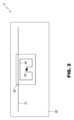
本発明をより良く理解するため、図1A及び1Bは、本発明の2つの代替的実施形態による2つのパッチRFIDデバイスを概略的に示す。とくに、図1A及び1Bそれぞれは、
・第1パッチRFIDデバイス(図1Aで全体として参照符号1Aにより示す)であって、第2アンテナとして第1MLA(図1Aで参照符号11Aにより示す)を装備し、この第1MLA11Aは、第1絶縁層(図1Aで参照符号13Aにより示す)上において部分的に延在し、また基板(図1Aで参照符号12Aにより示す)上において部分的に延在する、該第1パッチRFIDデバイス、及び
・第2パッチRFIDデバイス(図1Bで全体として参照符号1Bにより示す)であって、第2アンテナとして第2MLA(図1Bで参照符号11Bにより示す)を装備し、この第2MLA11Bは、第1絶縁層(図1Aで参照符号13Bにより示す)上において全体的に延在する、該第2パッチRFIDデバイス
それぞれの頂面図を示す。For a better understanding of the invention, FIGS. 1A and 1B schematically show two patch RFID devices according to two alternative embodiments of the invention. In particular, FIGS. 1A and 1B each show:
a first patch RFID device (indicated generally by
このことに関連して、説明を分かり易くするため、図1A及び1Bには第2絶縁層及び頂部ゴム層は示さず、基板(図1Aでは参照符号12A、及び図1Bでは参照符号12Bにより示す)、第1絶縁層13A、13B、RFIDチップ(図1A及び1Bにおいてそれぞれ14A及び14Bによって示す)、及び第1アンテナ(図1A及び1Bにおいてそれぞれ15A及び15Bによって示す)がはっきりと見えるようにしていることに留意するのは重要である。 In this regard, for clarity of illustration, FIGS. 1A and 1B do not show the second insulating layer and the top rubber layer, and the substrate (indicated by
さらに、図2及び3は、本発明の教示に基づくパッチRFIDデバイスにおける2つの他の非限定的実施例を概略的に示す。とくに、図2及び3は、
・第3パッチRFIDデバイス(図2で全体として参照符号2により示す)であって、第2アンテナとして真直ぐな無給電放射体(図2で参照符号21により示す)を装備した、該第3パッチRFIDデバイス、及び
・第4パッチRFIDデバイス(図3で全体として参照符号3により示す)であって、撚った導電性ワイヤ及び非導電性ワイヤのアセンブリによって形成した第2アンテナを装備した、該第4パッチRFIDデバイス
それぞれの頂面図を示す。Further, Figures 2 and 3 schematically show two other non-limiting examples of patch RFID devices according to the teachings of the present invention. In particular, Figures 2 and 3 show
- a third patch RFID device (indicated generally by
さらに、図2及び3に関連して、説明を分かり易くするため、第2絶縁層及び頂部ゴム層は示さず、基板(図2及び3ではそれぞれ参照符号22、32により示す)、第1絶縁層(図2及び3ではそれぞれ参照符号23、33により示す)、RFIDチップ(図2及び3においてそれぞれ24及び34によって示す)、及び第1アンテナ(図2及び3においてそれぞれ25及び35によって示す)がはっきりと見えるようにしていることに留意するのは重要である。 Further, with respect to FIGS. 2 and 3, for clarity of illustration, the second insulating layer and the top rubber layer are not shown, and the substrate (indicated by
とくに図3につき説明すると、第4パッチRFIDデバイス3における第2アンテナは、
・第1アンテナ35の周りを部分的に包囲して、これと電磁的(好適には、誘導的)結合を生ずるようにしたU字状部分31Aであって、第1アンテナ35の両側サイドに位置付けられる2つの端部を有する、該U字状部分31Aと、
・第1アンテナ35から互いに反対方向に延在する2つの真直ぐなアーム31Bであって、各々はU字状部分31Aの対応する端部から延在する、該アーム31Bと
を備え、
U字状部分31A及び2つの真直ぐなアーム31Bは、撚った導電性ワイヤ及び非導電性ワイヤの1つの同一アセンブリによって形成され、撚った導電性ワイヤ及び非導電性ワイヤのアセンブリは、補強メッシュ36と織り合わされて、この補強メッシュは、
・U字状部分がそのU字形状を有しかつ維持し、また
・2つの真直ぐなアーム31Bがその真直ぐな形状を有しかつ維持する
ようにさせるものである。With particular reference to Figure 3, the second antenna in the fourth patch RFID device 3 comprises:
A
two
The
- the U-shaped portion has and maintains its U-shape; and - the two
第3及び第4のパッチRFIDデバイス2及び3の代替的バージョンによれば、第2アンテナ(真直ぐな無給電放射体によって又は撚った導電性ワイヤ及び非導電性ワイヤのアセンブリによってそれぞれ形成される)は、都合よくは、この場合、より大きな平面状サイズを有する第1絶縁層上において全体的に延在することができ(さらに、第2アンテナは、やはりより大きな平面状サイズを有する第2絶縁層によって完全にカバーされる)。 According to alternative versions of the third and fourth
より全体的には、第1絶縁層と第2絶縁層(対応するより大きい又はより小さい平面状サイズを有する)との間に完全に又は部分的に挟持される第2アンテナの使用には賛否両論がある。すなわち、より大きい平面状サイズを有し、また両絶縁層間に完全に挟持される第2アンテナを有する第1及び第2の絶縁層の使用は、この利点が多層平面状構体の可撓性を僅かに低下させる犠牲を払うことになるにしても、第2アンテナをより効果的に保護すること可能にする。他方、第1及び第2の絶縁層に対してより小さい平面状サイズを使用し、この場合、第2アンテナが第1及び第2の絶縁層間に部分的に挟持され、また基板と頂部ゴム層/タイヤ内側ライナーとの間に部分的に挟持されることは、多層平面状構体の可撓性を増大させることができる(ただし残念なことに、第1及び第2の絶縁層で形成されるサンドイッチと、基板及び頂部ゴム層/タイヤ内側ライナーによって形成されるサンドイッチとの間の端縁における第2アンテナの脆弱性をより高める犠牲を払うことになり得る)。 More generally, the use of a second antenna that is wholly or partially sandwiched between a first insulating layer and a second insulating layer (having a corresponding larger or smaller planar size) is for or against the use of There are two arguments. That is, the use of first and second insulating layers having a larger planar size and having the second antenna fully sandwiched between the insulating layers, this advantage enhances the flexibility of the multi-layer planar structure. It allows more effective protection of the secondary antenna, albeit at the expense of slightly lowering it. On the other hand, a smaller planar size is used for the first and second insulation layers, in which case the second antenna is partially sandwiched between the first and second insulation layers, and the substrate and top rubber layer / Being partially sandwiched between the tire inner liner can increase the flexibility of the multi-layer planar structure (unfortunately, the at the expense of making the second antenna more vulnerable at the edge between the sandwich and the sandwich formed by the substrate and top rubber layer/tire innerliner).
上述したことから、本発明の技術的利点及び革新的特徴は当業者であれば即座に分かるであろう。 From the foregoing, those skilled in the art will readily appreciate the technical advantages and innovative features of the present invention.
とくに、本発明は、概して、現在既知の解決法と比べると向上した性能及び特徴を有する、またとくに、タイヤ又はタイヤコードに損傷を引き起こすことを回避するタイヤのためのパッチRFIDデバイスを提供することを指摘するのは重要である。 In particular, the present invention generally provides a patch RFID device for tires that has improved performance and characteristics compared to currently known solutions, and in particular avoids causing damage to tires or tire cords. It is important to point out
さらにまた、本発明、及び本発明の特別な随意的特徴における多くのさらなる技術的利点を詳細に説明してきた。 Furthermore, many additional technical advantages of the present invention and certain optional features of the present invention have been described in detail.
結論として、多くの変更及び改変を本発明に加えることができるのは明らかであり、これら変更及び改変のすべては、特許請求の範囲で定義される本発明の範囲内にある。
In conclusion, it is evident that many variations and modifications can be made to the present invention, all of which are within the scope of the invention as defined in the claims.
Claims (20)
Translated fromJapanese・基板(12A、12B、22、32)と、
・前記基板(12A、12B、22、32)の第1部分をカバーし、これにより前記第1部分周りに延在する第2部分を露出させたままにする第1絶縁層(13A、13B、23、33)と、
・前記第1絶縁層(13A、13B、23、33)上で互いに接続かつ配設された無線周波数識別チップ(14A、14B、24、34)及び第1アンテナ(15A、15B、25、35)と、
・前記第1アンテナ(15A、15B、25、35)に電磁的に結合され、また前記第1絶縁層(13A、13B、23、33)上で少なくとも部分的に延在する第2アンテナ(11A、11B、21、31A~31B)であって、前記無線周波数識別チップ(14A、14B、24、34)、前記第1アンテナ(15A、15B、25、35)及び前記第2アンテナ(11A、11B、21、31A~31B)が1つの同一平面上に存在し、前記第2アンテナ(11A、11B、21、31A~31B)が無給電放射体である、該第2アンテナ(11A、11B、21、31A~31B)と、
・前記第1絶縁層(13A、13B、23、33)、前記無線周波数識別チップ(14A、14B、24、34)、前記第1アンテナ(15A、15B、25、35)をカバーし、また少なくとも部分的に前記第2アンテナ(11A、11B、21、31A~31B)をカバーする第2絶縁層と
を有し、
前記第2アンテナ(11A、11B、21、31A~31B)は、少なくとも部分的に前記第1絶縁層(13A、13B、23、33)と前記第2絶縁層との間に挟持されている、パッチ無線周波数識別デバイス。A patch radio frequency identification device (1A, 1B, 2, 3) designed for application to a tire inner liner before or after tire vulcanization/curing and comprising a flexible multi-layer planar structure, said The planar structure is
- substrates (12A, 12B, 22, 32);
- a first insulating layer (13A, 13B, 13A, 13B, 13A, 13B, 13A, 13B, 13A, 13B, 13A, 13B, 13A, 13B, 13A, 13B, 13A, 13B, 13A, 13B, 13A, 13B, 13A, 13B, 13A, 13B, 13A, 13B, 13A, 13B, 13A, 13B, 13A, 13B, 23, 33) and
- a radio frequency identification chip (14A, 14B, 24, 34) and a first antenna (15A, 15B, 25, 35) connected to each other and arranged on said first insulating layer (13A, 13B, 23, 33); and,
a second antenna (11A) electromagnetically coupled to said first antenna (15A, 15B, 25, 35) and extending at least partially over said first insulating layer (13A, 13B, 23, 33); , 11B, 21, 31A-31B), wherein said radio frequency identification chip (14A, 14B, 24, 34), said first antenna (15A, 15B, 25, 35) and said second antenna (11A, 11B , 21, 31A-31B) are present on one same plane, and the second antennas (11A, 11B, 21, 31A-31B) are parasitic radiators (11A, 11B, 21 , 31A-31B) and
- covering said first insulating layer (13A, 13B, 23, 33), said radio frequency identification chip (14A, 14B, 24, 34), said first antenna (15A, 15B, 25, 35), and at least a second insulating layer partially covering the second antenna (11A, 11B, 21, 31A-31B);
said second antenna (11A, 11B, 21, 31A-31B) is at least partially sandwiched between said first insulating layer (13A, 13B, 23, 33) and said second insulating layer; Patch radio frequency identification device.
・前記第1絶縁層(13A、23、33)上で少なくとも部分的に延在し、また前記基板(12A、22、32)の第2部分上で少なくとも部分的に延在し、また前記第2絶縁層によって部分的にカバーされる、又は
・前記第1絶縁層(13A、23、33)上で完全に延在し、また前記第2絶縁層によって完全にカバーされる、パッチ無線周波数識別デバイス。The patch radio frequency identification device of claim 1, wherein said second antenna (11A, 11B, 21, 31A-31B) comprises:
extending at least partially over said first insulating layer (13A, 23, 33) and at least partially over a second portion of said substrate (12A, 22, 32); a patch radio frequency identification partially covered by two insulating layers, or extending completely over said first insulating layer (13A, 23, 33) and completely covered by said second insulating layer device.
・前記第1絶縁層(13A、13B、23、33)上で延在し、また前記第2絶縁層によってカバーされる第1部分(31A)と、
・第2部分(31B)であって、
- 前記第1絶縁層(13B、23、33)上で前記第1部分(31A)から延在し、また前記第2絶縁層によってカバーされる、又は
- 前記基板(12A、22、32)の前記第2部分における前記第1部分(31A)から延在し、また前記第2絶縁層によってカバーされない、該第2部分(31B)と
を有する、パッチ無線周波数識別デバイス。The patch radio frequency identification device of claim 2, wherein said second antenna (11A, 11B, 21, 31A-31B) comprises:
a first portion (31A) extending over said first insulating layer (13A, 13B, 23, 33) and covered by said second insulating layer;
a second portion (31B),
- extends from said first portion (31A) over said first insulating layer (13B, 23, 33) and is also covered by said second insulating layer, or
- a patch having a second portion (31B) extending from said first portion (31A) in said second portion of said substrate (12A, 22, 32) and not covered by said second insulating layer; Radio frequency identification device.
・真直ぐな導電性ワイヤ、又は
・撚った導電性ワイヤのアセンブリ、又は
・撚った導電性ワイヤ及び非導電性ワイヤのアセンブリ
によって形成される、パッチ無線周波数識別デバイス。The patch radio frequency identification device according to any one of claims 1-7, wherein said second antenna (21, 31A-31B) comprises:
A patch radio frequency identification device formed by: a straight conductive wire, or an assembly of stranded conductive wires, or an assembly of stranded conductive and non-conductive wires.
・前記第1アンテナ(35)及び前記第2アンテナの第1部分(31A)の相対部分が前記2つのアンテナ間に電磁的結合を生ずるようにし、
・前記第2アンテナの第1部分(31A)が前記第1アンテナ(35)の両側サイドに位置付けられる2つの端部を有し、また
・前記第2アンテナの第2部分(31B)が前記第1アンテナ(35)から反対方向に延在する2つの真直ぐなアームを有し、各アームは、前記第2アンテナの第1部分(31A)の対応する端部から延在する
ものである、パッチ無線周波数識別デバイス。The patch radio frequency identification device of claim 3, wherein said first antenna (35) is a two-dimensional folded structure and said second antenna (31A-31B) is an assembly of twisted conductive wires or a twisted formed by an assembly of conductive and non-conductive wires,
- the relative parts of said first antenna (35) and said first part (31A) of said second antenna create an electromagnetic coupling between said two antennas;
- the first part (31A) of the second antenna has two ends positioned on opposite sides of the first antenna (35); and - the second part (31B) of the second antenna A patch having two straight arms extending in opposite directions from one antenna (35), each arm extending from a corresponding end of a first portion (31A) of said second antenna Radio frequency identification device.
前記多層平面状構体は、さらに、前記無線周波数識別チップ(34)、前記第1アンテナ(35)、前記第1絶縁層(33)、及び少なくとも部分的に基板(32)の第2部分に取り付けられた補強メッシュ(36)を有し、また
前記撚った導電性ワイヤ及び非導電性ワイヤのアセンブリは前記補強メッシュ(36)と織り合わされて、前記補強メッシュ(36)は、前記撚った導電性ワイヤ及び非導電性ワイヤのアセンブリに対して前記第2アンテナの第1部分(31A)及び第2部分(31B)の形状を維持させるものである、パッチ無線周波数識別デバイス。A patch radio frequency identification device according to claim 11, wherein said second antenna (31A-31B) is formed by an assembly of twisted conductive and non-conductive wires,
Said multi-layer planar structure is further attached to said radio frequency identification chip (34), said first antenna (35), said first insulating layer (33) and at least partially to a second portion of a substrate (32). and the assembly of twisted conductive and non-conductive wires is interwoven with the reinforcing mesh (36), and the reinforcing mesh (36) comprises the twisted A patch radio frequency identification device which causes the first part (31A) and the second part (31B) of said second antenna to maintain shape with respect to an assembly of conducting and non-conducting wires.
・パッチ無線周波数識別デバイス(1A、1B、2、3)が埋設されている前記タイヤに割り当てられる一義的な識別子を記憶し、
・前記第2アンテナ(11A、11B、21、31A~31B)及び前記第1アンテナ(15A、15B、25、35)を介して無線周波数識別リーダーからの呼掛け信号を受信し、また
・前記第1アンテナ(15A、15B、25、35)及び前記第2アンテナ(11A、11B、21、31A~31B)を介して後方散乱した前記一義的な識別子を搬送している呼掛け信号を送信する
よう構成される、パッチ無線周波数識別デバイス。The patch radio frequency identification device of any one of claims 1-13, wherein the radio frequency identification chip (14A, 14B, 24, 34) comprises:
- store a unique identifier assigned to said tire in which a patch radio frequency identification device (1A, 1B, 2, 3) is embedded;
- receives an interrogation signal from a radio frequency identification reader via said second antenna (11A, 11B, 21, 31A-31B) and said first antenna (15A, 15B, 25, 35); to transmit an interrogation signal carrying said unique identifier backscattered via one antenna (15A, 15B, 25, 35) and said second antenna (11A, 11B, 21, 31A-31B); A patch radio frequency identification device, comprising:
・前記無線周波数識別チップ(14A、14B、24、34)及び前記第1アンテナ(15A、15B、25、35)と、
・前記第2絶縁層と
の間に介在させる、パッチ無線周波数識別デバイス。The patch radio frequency identification device of any one of claims 1-17, wherein the protective resin comprises:
- said radio frequency identification chip (14A, 14B, 24, 34) and said first antenna (15A, 15B, 25, 35);
- A patch radio frequency identification device interposed between said second insulating layer.
Applications Claiming Priority (3)
| Application Number | Priority Date | Filing Date | Title |
|---|---|---|---|
| IT102019000002337AIT201900002337A1 (en) | 2019-02-18 | 2019-02-18 | PERFECTED RFID DEVICE FOR TIRES |
| IT102019000002337 | 2019-02-18 | ||
| PCT/IB2020/050829WO2020170057A1 (en) | 2019-02-18 | 2020-02-03 | Improved rfid device for tires |
Publications (2)
| Publication Number | Publication Date |
|---|---|
| JP2022519907A JP2022519907A (en) | 2022-03-25 |
| JP7317132B2true JP7317132B2 (en) | 2023-07-28 |
Family
ID=66476756
Family Applications (1)
| Application Number | Title | Priority Date | Filing Date |
|---|---|---|---|
| JP2021548157AActiveJP7317132B2 (en) | 2019-02-18 | 2020-02-03 | Improved RFID device for tires |
Country Status (6)
| Country | Link |
|---|---|
| US (2) | US12106170B2 (en) |
| EP (1) | EP3927562B1 (en) |
| JP (1) | JP7317132B2 (en) |
| CN (1) | CN113439033A (en) |
| IT (1) | IT201900002337A1 (en) |
| WO (1) | WO2020170057A1 (en) |
Families Citing this family (22)
| Publication number | Priority date | Publication date | Assignee | Title |
|---|---|---|---|---|
| KR20220073735A (en)* | 2019-08-22 | 2022-06-03 | 파인라인 테크놀로지스 | Chemically-treated RFID-equipped mesh tire labels for identification and tracking purposes during and after tire manufacturing and methods of making and using the same |
| JP7457519B2 (en)* | 2020-02-18 | 2024-03-28 | 株式会社ブリヂストン | aircraft tires |
| IT202000012595A1 (en) | 2020-05-27 | 2021-11-27 | Bridgestone Europe Nv Sa | IMPROVED RFID SENSOR DEVICE WITH PATCH TYPE ANTENNA FOR TIRES |
| US11824373B2 (en) | 2021-11-03 | 2023-11-21 | Nucurrent, Inc. | Wireless power transmission antenna with parallel coil molecule configuration |
| US12027880B2 (en) | 2021-11-03 | 2024-07-02 | Nucurrent, Inc. | Wireless power transfer from mouse pad to mouse |
| US11831175B2 (en) | 2021-11-03 | 2023-11-28 | Nucurrent, Inc. | Wireless power transmission antenna with antenna molecules |
| US11831176B2 (en) | 2021-11-03 | 2023-11-28 | Nucurrent, Inc. | Wireless power transfer systems with substantial uniformity over a large area |
| US20230145030A1 (en)* | 2021-11-03 | 2023-05-11 | Nucurrent, Inc. | Wireless Power Transmitter with Metal Mesh for Resiliency |
| US11824372B2 (en) | 2021-11-03 | 2023-11-21 | Nucurrent, Inc. | Wireless power transmission antenna with puzzled antenna molecules |
| US11831177B2 (en) | 2021-11-03 | 2023-11-28 | Nucurrent, Inc. | Wireless power transmitter with internal repeater and enhanced uniformity |
| US11848566B2 (en) | 2021-11-03 | 2023-12-19 | Nucurrent, Inc. | Dual communications demodulation of a wireless power transmission system having an internal repeater |
| US11824371B2 (en) | 2021-11-03 | 2023-11-21 | Nucurrent, Inc. | Wireless power transmission antenna with internal repeater and repeater filter |
| US11862991B2 (en) | 2021-11-03 | 2024-01-02 | Nucurrent, Inc. | Wireless power transmission antenna with internal repeater and in-coil tuning |
| US11831173B2 (en) | 2021-11-03 | 2023-11-28 | Nucurrent, Inc. | Wireless power transmission antenna with series coil molecule configuration |
| US11962337B2 (en) | 2021-11-03 | 2024-04-16 | Nucurrent, Inc. | Communications demodulation in wireless power transmission system having an internal repeater |
| US11862984B2 (en) | 2021-11-03 | 2024-01-02 | Nucurrent, Inc. | Wireless power receiver with repeater for enhanced power harvesting |
| IT202100032225A1 (en)* | 2021-12-22 | 2023-06-22 | Bridgestone Europe Nv Sa | METHOD OF PRODUCTION OF A TIRE EQUIPPED WITH AN ELECTRONIC DEVICE |
| US20250307590A1 (en)* | 2022-07-07 | 2025-10-02 | Kordsa Teknik Tekstil Anonim Sirketi | Contactlessly activated rfid tag for tire |
| US12431632B2 (en)* | 2023-03-03 | 2025-09-30 | Meta Platforms Technologies, Llc | Systems and methods for integrating antennas into textile bands |
| KR102636494B1 (en)* | 2023-06-28 | 2024-02-14 | 주식회사 윌켐코리아 | RFID tag for tire burial with improved transmission and reception sensitivity |
| WO2025027996A1 (en)* | 2023-07-28 | 2025-02-06 | 株式会社村田製作所 | Rfid tag and tire |
| KR102734497B1 (en)* | 2024-02-07 | 2024-11-26 | 주식회사 윌켐코리아 | Manufacturing method of a wireless recognition tag for tire attachment that suppresses air bubbles and improves durability |
Citations (8)
| Publication number | Priority date | Publication date | Assignee | Title |
|---|---|---|---|---|
| US20040182494A1 (en) | 2003-03-19 | 2004-09-23 | Dominak Stephen L. | Tag attachment for tires and method of attaching tags to tires |
| US20100122757A1 (en) | 2008-11-18 | 2010-05-20 | Robert Edward Lionetti | Tire and electronic device assembly |
| CN201489565U (en) | 2009-09-01 | 2010-05-26 | 上海韩硕信息科技有限公司 | Flexible UHF frequency range RFID label |
| US20120152028A1 (en) | 2010-12-16 | 2012-06-21 | Electronics And Telecommunications Research Institute | Power supplier using flexible pcb based on self-powering and sensor node using the same |
| JP2014147097A (en) | 2009-04-14 | 2014-08-14 | Murata Mfg Co Ltd | Wireless IC device |
| WO2017130956A1 (en) | 2016-01-25 | 2017-08-03 | トッパン・フォームズ株式会社 | Tire with embedded rfid tag |
| CN206584389U (en) | 2016-11-15 | 2017-10-24 | 刘台华 | Inductive coupling type RFID antenna device |
| US20180174015A1 (en) | 2015-06-03 | 2018-06-21 | Compagnie Generale Des Etablissements Michelin | Radiofrequency transponder for a tire |
Family Cites Families (18)
| Publication number | Priority date | Publication date | Assignee | Title |
|---|---|---|---|---|
| US5479171A (en)* | 1993-04-27 | 1995-12-26 | Texas Instruments Deutschland Gmbh | Extended range RF-ID transponder |
| JPH0730104U (en)* | 1993-11-12 | 1995-06-06 | 株式会社ブリヂストン | Pneumatic tire with built-in transponder |
| US20040159383A1 (en)* | 2002-06-11 | 2004-08-19 | Adamson John David | Method for embedding a radio frequency antenna in a tire, and an antenna for embedding in a tire |
| US6854324B2 (en)* | 2002-12-20 | 2005-02-15 | The Goodyear Tire & Rubber Company | Tire monitoring apparatus |
| US7091841B2 (en)* | 2003-02-19 | 2006-08-15 | Michelin Recherche Et Technique, S.A. | Tire electronics assembly having a multi-frequency antenna |
| EP1880444A1 (en)* | 2005-05-13 | 2008-01-23 | Fractus, S.A. | Antenna diversity system and slot antenna component |
| US7825868B2 (en)* | 2007-06-15 | 2010-11-02 | Emag Technologies, Inc. | Hand held reader antenna for RFID and tire pressure monitoring system |
| FR2937284B1 (en)* | 2008-10-20 | 2010-11-19 | Michelin Soc Tech | INSTRUMENT PNEUMATIC AND PNEUMATIC BODY |
| IT1401990B1 (en)* | 2010-09-30 | 2013-08-28 | Pirelli | METHOD AND SYSTEM TO DETERMINE POTENTIAL FRICTION BETWEEN A TIRE FOR VEHICLES AND A ROLLING SURFACE |
| JP2012240603A (en)* | 2011-05-23 | 2012-12-10 | Yokohama Rubber Co Ltd:The | Pneumatic tire |
| KR101545385B1 (en) | 2013-05-15 | 2015-08-18 | 아시아나아이디티 주식회사 | An management system for manufacturing tires using rfid tag |
| CN103546188A (en) | 2013-10-30 | 2014-01-29 | 西安乾易企业管理咨询有限公司 | Wireless mobile terminal of self-tuning antenna and adjusting method of self-tuning antenna |
| US20150248569A1 (en)* | 2014-03-03 | 2015-09-03 | Berntsen International, Inc. | Advanced System for Navigating Between, Locating and Monitoring Underground Assets |
| ES2670649T3 (en)* | 2015-03-02 | 2018-05-31 | Gemalto Sa | Manufacturing procedure of a radio frequency device with passive wired antenna |
| TWI626790B (en)* | 2016-08-18 | 2018-06-11 | Read Tag Tech Corp | Long-distance radio frequency electronic identification tire structure |
| US20180151949A1 (en)* | 2016-11-30 | 2018-05-31 | Trw Automotive Us Llc | Antenna with parasitic element |
| FR3059592A1 (en) | 2016-12-05 | 2018-06-08 | Compagnie Generale Des Etablissements Michelin | METHOD FOR MANUFACTURING A PATCH EQUIPPED WITH A RADIOFREQUENCY AND PNEUMATIC TRANSPONDER COMPRISING SUCH A PATCH |
| CN107116977B (en)* | 2017-05-23 | 2023-07-14 | 山东玲珑轮胎股份有限公司 | a smart tire |
- 2019
- 2019-02-18ITIT102019000002337Apatent/IT201900002337A1/enunknown
- 2020
- 2020-02-03CNCN202080014893.9Apatent/CN113439033A/enactivePending
- 2020-02-03JPJP2021548157Apatent/JP7317132B2/enactiveActive
- 2020-02-03WOPCT/IB2020/050829patent/WO2020170057A1/ennot_activeCeased
- 2020-02-03USUS17/424,303patent/US12106170B2/enactiveActive
- 2020-02-03EPEP20703301.0Apatent/EP3927562B1/enactiveActive
- 2024
- 2024-08-30USUS18/821,440patent/US20240419935A1/enactivePending
Patent Citations (8)
| Publication number | Priority date | Publication date | Assignee | Title |
|---|---|---|---|---|
| US20040182494A1 (en) | 2003-03-19 | 2004-09-23 | Dominak Stephen L. | Tag attachment for tires and method of attaching tags to tires |
| US20100122757A1 (en) | 2008-11-18 | 2010-05-20 | Robert Edward Lionetti | Tire and electronic device assembly |
| JP2014147097A (en) | 2009-04-14 | 2014-08-14 | Murata Mfg Co Ltd | Wireless IC device |
| CN201489565U (en) | 2009-09-01 | 2010-05-26 | 上海韩硕信息科技有限公司 | Flexible UHF frequency range RFID label |
| US20120152028A1 (en) | 2010-12-16 | 2012-06-21 | Electronics And Telecommunications Research Institute | Power supplier using flexible pcb based on self-powering and sensor node using the same |
| US20180174015A1 (en) | 2015-06-03 | 2018-06-21 | Compagnie Generale Des Etablissements Michelin | Radiofrequency transponder for a tire |
| WO2017130956A1 (en) | 2016-01-25 | 2017-08-03 | トッパン・フォームズ株式会社 | Tire with embedded rfid tag |
| CN206584389U (en) | 2016-11-15 | 2017-10-24 | 刘台华 | Inductive coupling type RFID antenna device |
Also Published As
| Publication number | Publication date |
|---|---|
| CN113439033A (en) | 2021-09-24 |
| IT201900002337A1 (en) | 2020-08-18 |
| EP3927562B1 (en) | 2024-03-27 |
| JP2022519907A (en) | 2022-03-25 |
| US20220134814A1 (en) | 2022-05-05 |
| EP3927562A1 (en) | 2021-12-29 |
| US20240419935A1 (en) | 2024-12-19 |
| US12106170B2 (en) | 2024-10-01 |
| WO2020170057A1 (en) | 2020-08-27 |
Similar Documents
| Publication | Publication Date | Title |
|---|---|---|
| JP7317132B2 (en) | Improved RFID device for tires | |
| KR100845474B1 (en) | LF ID tag for tire laying | |
| US7345643B2 (en) | Wave antenna wireless communication device and method | |
| EP3532995B1 (en) | Rfid tags designed to work on difficult substrates | |
| US7394438B2 (en) | Wave antenna wireless communication device and method | |
| EP2920010B1 (en) | Rfid tag with rubber, elastomer, or polymer antenna | |
| US10878306B2 (en) | RFID transponder antenna | |
| US10268940B2 (en) | Stretchable broad impedance bandwidth RFID devices | |
| CN116529735B (en) | RFID tag for rubber product and method for manufacturing RFID tag for rubber product | |
| KR20130108797A (en) | Rfid tag for tire | |
| JP7410488B2 (en) | RF tag labels and rubber products with RF tag labels | |
| WO2020075469A1 (en) | Rf tag label and rubber product equipped with rf tag label | |
| EP3549067B1 (en) | Improving performance of rfid tags | |
| RU2796701C2 (en) | Improved tire rfid | |
| KR100898603B1 (en) | Integrated RFID ID tag and manufacturing method | |
| EP3688668B1 (en) | Strap mounting techniques for wire format antennas | |
| KR101113851B1 (en) | RFID tag | |
| CN221261664U (en) | High-reliability RFID tag | |
| EP4303761B1 (en) | A contactlessly activated rfid tag for a tire | |
| US20250307590A1 (en) | Contactlessly activated rfid tag for tire | |
| CN117744692A (en) | High-reliability RFID tag | |
| WO2022091440A1 (en) | Rubber product rfid tag and method for manufacturing rubber product rfid tag | |
| JPWO2020075732A1 (en) | RF tags embedded in tires and tires with built-in RF tags | |
| KR20090002353U (en) | Radio Frequency Identification Label for Tire |
Legal Events
| Date | Code | Title | Description |
|---|---|---|---|
| A621 | Written request for application examination | Free format text:JAPANESE INTERMEDIATE CODE: A621 Effective date:20211012 | |
| A131 | Notification of reasons for refusal | Free format text:JAPANESE INTERMEDIATE CODE: A131 Effective date:20221220 | |
| A521 | Request for written amendment filed | Free format text:JAPANESE INTERMEDIATE CODE: A523 Effective date:20230308 | |
| TRDD | Decision of grant or rejection written | ||
| A01 | Written decision to grant a patent or to grant a registration (utility model) | Free format text:JAPANESE INTERMEDIATE CODE: A01 Effective date:20230711 | |
| A61 | First payment of annual fees (during grant procedure) | Free format text:JAPANESE INTERMEDIATE CODE: A61 Effective date:20230718 | |
| R150 | Certificate of patent or registration of utility model | Ref document number:7317132 Country of ref document:JP Free format text:JAPANESE INTERMEDIATE CODE: R150 |