JP7317024B2 - Image generation device and image generation method - Google Patents
Image generation device and image generation methodDownload PDFInfo
- Publication number
- JP7317024B2 JP7317024B2JP2020537981AJP2020537981AJP7317024B2JP 7317024 B2JP7317024 B2JP 7317024B2JP 2020537981 AJP2020537981 AJP 2020537981AJP 2020537981 AJP2020537981 AJP 2020537981AJP 7317024 B2JP7317024 B2JP 7317024B2
- Authority
- JP
- Japan
- Prior art keywords
- augmented reality
- image
- user
- body part
- area
- Prior art date
- Legal status (The legal status is an assumption and is not a legal conclusion. Google has not performed a legal analysis and makes no representation as to the accuracy of the status listed.)
- Active
Links
Images


Classifications
- G—PHYSICS
- G06—COMPUTING OR CALCULATING; COUNTING
- G06T—IMAGE DATA PROCESSING OR GENERATION, IN GENERAL
- G06T19/00—Manipulating 3D models or images for computer graphics
- G06T19/006—Mixed reality
- G—PHYSICS
- G06—COMPUTING OR CALCULATING; COUNTING
- G06F—ELECTRIC DIGITAL DATA PROCESSING
- G06F3/00—Input arrangements for transferring data to be processed into a form capable of being handled by the computer; Output arrangements for transferring data from processing unit to output unit, e.g. interface arrangements
- G06F3/01—Input arrangements or combined input and output arrangements for interaction between user and computer
- G06F3/011—Arrangements for interaction with the human body, e.g. for user immersion in virtual reality
- G06F3/014—Hand-worn input/output arrangements, e.g. data gloves
- G—PHYSICS
- G06—COMPUTING OR CALCULATING; COUNTING
- G06F—ELECTRIC DIGITAL DATA PROCESSING
- G06F3/00—Input arrangements for transferring data to be processed into a form capable of being handled by the computer; Output arrangements for transferring data from processing unit to output unit, e.g. interface arrangements
- G06F3/01—Input arrangements or combined input and output arrangements for interaction between user and computer
- G06F3/048—Interaction techniques based on graphical user interfaces [GUI]
- G06F3/0481—Interaction techniques based on graphical user interfaces [GUI] based on specific properties of the displayed interaction object or a metaphor-based environment, e.g. interaction with desktop elements like windows or icons, or assisted by a cursor's changing behaviour or appearance
- G—PHYSICS
- G06—COMPUTING OR CALCULATING; COUNTING
- G06T—IMAGE DATA PROCESSING OR GENERATION, IN GENERAL
- G06T7/00—Image analysis
- G06T7/70—Determining position or orientation of objects or cameras
- H—ELECTRICITY
- H04—ELECTRIC COMMUNICATION TECHNIQUE
- H04N—PICTORIAL COMMUNICATION, e.g. TELEVISION
- H04N13/00—Stereoscopic video systems; Multi-view video systems; Details thereof
- H04N13/20—Image signal generators
- H04N13/275—Image signal generators from 3D object models, e.g. computer-generated stereoscopic image signals
- H04N13/279—Image signal generators from 3D object models, e.g. computer-generated stereoscopic image signals the virtual viewpoint locations being selected by the viewers or determined by tracking
- G—PHYSICS
- G06—COMPUTING OR CALCULATING; COUNTING
- G06T—IMAGE DATA PROCESSING OR GENERATION, IN GENERAL
- G06T2215/00—Indexing scheme for image rendering
- G06T2215/16—Using real world measurements to influence rendering
Landscapes
- Engineering & Computer Science (AREA)
- Theoretical Computer Science (AREA)
- General Engineering & Computer Science (AREA)
- Physics & Mathematics (AREA)
- General Physics & Mathematics (AREA)
- Human Computer Interaction (AREA)
- Multimedia (AREA)
- Signal Processing (AREA)
- Computer Graphics (AREA)
- Computer Hardware Design (AREA)
- Software Systems (AREA)
- Computer Vision & Pattern Recognition (AREA)
- User Interface Of Digital Computer (AREA)
- Processing Or Creating Images (AREA)
Description
Translated fromJapaneseこの発明は、画像を生成する装置および方法に関する。 The present invention relates to apparatus and methods for generating images.
ゲーム機に接続されたヘッドマウントディスプレイを頭部に装着して、ヘッドマウントディスプレイに表示された画面を見ながら、コントローラなどを操作してゲームプレイすることが行われている。ヘッドマウントディスプレイを装着すると、ヘッドマウントディスプレイに表示される映像以外はユーザは見ないため、映像世界への没入感が高まり、ゲームのエンタテインメント性を一層高める効果がある。また、ヘッドマウントディスプレイに仮想現実(VR(Virtual Reality))の映像を表示させ、ヘッドマウントディスプレイを装着したユーザが頭部を回転させると、360度見渡せる全周囲の仮想空間が表示されるようにすると、さらに映像への没入感が高まり、ゲームなどのアプリケーションの操作性も向上する。 A head-mounted display connected to a game machine is worn on the head, and a game is played by operating a controller or the like while viewing a screen displayed on the head-mounted display. When the user wears the head-mounted display, the user does not see anything other than the image displayed on the head-mounted display, so that the sense of immersion in the image world is enhanced, which has the effect of further enhancing the entertainment of the game. In addition, a virtual reality (VR) image is displayed on a head-mounted display, and when the user wearing the head-mounted display rotates his or her head, a 360-degree panoramic view of the virtual space is displayed. As a result, the feeling of being immersed in the video is further enhanced, and the operability of applications such as games is also improved.
また、非透過型ヘッドマウントディスプレイを装着したユーザは外界を直接見ることができなくなるが、ヘッドマウントディスプレイに搭載されたカメラによって外界の映像を撮影してディスプレイパネルに表示することのできるビデオ透過(ビデオシースルー)型ヘッドマウントディスプレイもある。ビデオ透過型ヘッドマウントディスプレイでは、カメラで撮影される外界の映像にコンピュータグラフィックス(CG(Computer Graphics))によって生成された仮想世界のオブジェクトを重畳させることで拡張現実(AR(Augmented Reality))の映像を生成して表示することもできる。拡張現実の映像は、現実世界から切り離された仮想現実とは違って、現実世界が仮想オブジェクトで拡張されたものであり、ユーザは現実世界とのつながりを意識しつつ、仮想世界を体験することができる。 In addition, although the user wearing the non-transmissive head-mounted display cannot directly see the outside world, the camera mounted on the head-mounted display can capture images of the outside world and display them on the display panel. There is also a video see-through) type head-mounted display. In a video transmissive head-mounted display, augmented reality (AR) is realized by superimposing virtual world objects generated by computer graphics (CG) on images of the outside world captured by a camera. You can also generate and display images. Unlike virtual reality, which is separated from the real world, augmented reality video is an extension of the real world with virtual objects, allowing users to experience the virtual world while being aware of the connection with the real world. can be done.
拡張現実の映像をヘッドマウントディスプレイに表示する際、ヘッドマウントディスプレイに搭載されたカメラで撮影される外界の映像に対して、CGによって生成された仮想世界のオブジェクトをいきなり重畳させると、実世界と仮想世界が非連続に結合するため、ユーザは違和感を感じることがある。 When an augmented reality image is displayed on a head-mounted display, if a virtual world object generated by CG is suddenly superimposed on the image of the outside world captured by the camera mounted on the head-mounted display, the real world will appear. Since the virtual world is discontinuously connected, the user may feel a sense of incongruity.
本発明はこうした課題に鑑みてなされたものであり、その目的は、拡張現実の映像の違和感を軽減することのできる画像生成装置および画像生成方法を提供することにある。 The present invention has been made in view of these problems, and its object is to provide an image generation device and an image generation method that can reduce the discomfort of augmented reality video.
上記課題を解決するために、本発明のある態様の画像生成装置は、ユーザの身体部位と現実世界の物体の接触の有無を判定する接触判定部と、前記身体部位が接触した前記現実世界の物体の箇所を含む部分空間を前記ユーザの視点から見た場合の領域を拡張現実領域として判定する拡張現実領域判定部と、前記現実世界の撮影画像の内、前記拡張現実領域に拡張現実画像を生成する拡張現実生成部とを含む。 In order to solve the above problems, an image generating apparatus according to one aspect of the present invention includes a contact determination unit that determines whether or not a body part of a user is in contact with an object in the real world; an augmented reality area determination unit that determines an area when a partial space including an object location is viewed from the user's point of view as an augmented reality area; and an augmented reality generator that generates.
本発明の別の態様は、画像生成方法である。この方法は、ユーザの身体部位と現実世界の物体の接触の有無を判定する接触判定ステップと、前記身体部位が接触した前記現実世界の物体の箇所を含む部分空間を前記ユーザの視点から見た場合の領域を拡張現実領域として判定する拡張現実領域判定ステップと、前記現実世界の撮影画像の内、前記拡張現実領域に拡張現実画像を生成する拡張現実生成ステップとを含む。 Another aspect of the invention is an image generation method. This method includes a contact determination step of determining whether or not a body part of a user is in contact with an object in the real world; and an augmented reality generation step of generating an augmented reality image in the augmented reality area in the captured image of the real world.
なお、以上の構成要素の任意の組合せ、本発明の表現を方法、装置、システム、コンピュータプログラム、データ構造、記録媒体などの間で変換したものもまた、本発明の態様として有効である。 Any combination of the above constituent elements, and expressions of the present invention converted between methods, devices, systems, computer programs, data structures, recording media, etc. are also effective as aspects of the present invention.
本発明によれば、拡張現実の映像の違和感を軽減することができる。 ADVANTAGE OF THE INVENTION According to this invention, the discomfort of the image|video of augmented reality can be reduced.
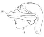
図1は、ヘッドマウントディスプレイ100の外観図である。ヘッドマウントディスプレイ100は、ユーザの頭部に装着してディスプレイに表示される静止画や動画などを鑑賞し、ヘッドホンから出力される音声や音楽などを聴くための表示装置である。 FIG. 1 is an external view of the head mounted
ヘッドマウントディスプレイ100に内蔵または外付けされたジャイロセンサや加速度センサなどによりヘッドマウントディスプレイ100を装着したユーザの頭部の位置情報と頭部の回転角や傾きなどの姿勢(orientation)情報を計測することができる。 A gyro sensor or an acceleration sensor built in or external to the head mounted
ヘッドマウントディスプレイ100にはカメラユニットが搭載されており、ユーザがヘッドマウントディスプレイ100を装着している間、外界を撮影することができる。 A camera unit is mounted on the head mounted
ヘッドマウントディスプレイ100は、「ウェアラブルディスプレイ」の一例である。ここでは、ヘッドマウントディスプレイ100に表示される画像の生成方法を説明するが、本実施の形態の画像生成方法は、狭義のヘッドマウントディスプレイ100に限らず、めがね、めがね型ディスプレイ、めがね型カメラ、ヘッドフォン、ヘッドセット(マイクつきヘッドフォン)、イヤホン、イヤリング、耳かけカメラ、帽子、カメラつき帽子、ヘアバンドなどを装着した場合にも適用することができる。 Head-mounted
図2は、本実施の形態に係る画像生成システムの構成図である。ヘッドマウントディスプレイ100は、一例として、映像・音声をデジタル信号で伝送する通信インタフェースの標準規格であるHDMI(登録商標)(High-Definition Multimedia Interface)などのインタフェース300で画像生成装置200に接続される。 FIG. 2 is a configuration diagram of an image generation system according to this embodiment. The head mounted
画像生成装置200は、ヘッドマウントディスプレイ100の現在の位置・姿勢情報から、映像の生成から表示までの遅延を考慮してヘッドマウントディスプレイ100の位置・姿勢情報を予測し、ヘッドマウントディスプレイ100の予測位置・姿勢情報を前提としてヘッドマウントディスプレイ100に表示されるべき画像を描画し、ヘッドマウントディスプレイ100に伝送する。 The
画像生成装置200の一例はゲーム機である。画像生成装置200は、さらにネットワークを介してサーバに接続されてもよい。その場合、サーバは、複数のユーザがネットワークを介して参加できるゲームなどのオンラインアプリケーションを画像生成装置200に提供してもよい。ヘッドマウントディスプレイ100は、画像生成装置200の代わりに、コンピュータや携帯端末に接続されてもよい。 An example of the
ユーザの身体部位が現実世界の物体と接触した箇所を少なくとも含む部分空間をユーザの視点から見た場合の領域に拡張現実領域が生成されて表示される。この拡張現実画像が表示される領域を「AR領域」と呼ぶ。たとえばユーザの手が現実世界のテーブルの上面の一部に接触した場合、テーブルの表面全体を部分空間とし、テーブルの表面をユーザの視点から見た場合の領域をAR領域とする。AR領域には、カメラによる撮影画像に所定のエフェクトや仮想オブジェクトの画像を重畳することで拡張現実画像を生成して表示してもよく、あるいは、カメラによる撮影画像の代わりにそれとは別のCG画像を生成して表示してもよい。 An augmented reality area is generated and displayed in a partial space including at least a portion where the user's body part comes into contact with an object in the real world, viewed from the user's viewpoint. A region in which the augmented reality image is displayed is called an “AR region”. For example, when a user's hand touches part of the top surface of a table in the real world, the entire surface of the table is defined as a partial space, and the area of the surface of the table viewed from the user's viewpoint is defined as the AR area. In the AR area, an augmented reality image may be generated and displayed by superimposing a predetermined effect or an image of a virtual object on the image taken by the camera, or alternatively, instead of the image taken by the camera, another CG may be displayed. An image may be generated and displayed.
ある実施例では、ユーザの身体部位にはトラッカ500が付けられる。トラッカ500は、慣性センサ、地磁気センサ、加速度センサ、モーションセンサなどのセンサを備え、ユーザの身体部位の位置や姿勢を検出することができる。ここでは、ユーザの手にトラッカ500を装着した例を説明するが、胴体や足など他の身体部位にトラッカ500を装着してもよい。ユーザの身体部位の位置および姿勢にもとづいて、ユーザの身体部位と現実世界の物体の接触の有無と、身体部位が接触した物体の箇所が決定される。トラッカ500は、ユーザの身体部位の位置および姿勢を画像生成装置200に送信する。 In one embodiment, a
別の実施例では、画像生成装置200は、カメラ画像においてユーザの身体部位を画像認識することによってユーザの身体部位の位置や姿勢を検出し、ユーザの身体部位と現実世界の物体の接触の有無と、身体部位が接触した物体の箇所を決定する。 In another embodiment, the
図3は、ヘッドマウントディスプレイ100の機能構成図である。 FIG. 3 is a functional configuration diagram of the head mounted
制御部10は、画像信号、センサ信号などの信号や、命令やデータを処理して出力するメインプロセッサである。入力インタフェース20は、ユーザからの操作信号や設定信号を受け付け、制御部10に供給する。出力インタフェース30は、制御部10から画像信号を受け取り、ディスプレイパネル32に表示する。 The
通信制御部40は、ネットワークアダプタ42またはアンテナ44を介して、有線または無線通信により、制御部10から入力されるデータを外部に送信する。通信制御部40は、また、ネットワークアダプタ42またはアンテナ44を介して、有線または無線通信により、外部からデータを受信し、制御部10に出力する。 The
記憶部50は、制御部10が処理するデータやパラメータ、操作信号などを一時的に記憶する。 The
姿勢センサ64は、ヘッドマウントディスプレイ100の位置情報と、ヘッドマウントディスプレイ100の回転角や傾きなどの姿勢情報を検出する。姿勢センサ64は、ジャイロセンサ、加速度センサ、角加速度センサなどを適宜組み合わせて実現される。3軸地磁気センサ、3軸加速度センサおよび3軸ジャイロ(角速度)センサの少なくとも1つ以上を組み合わせたモーションセンサを用いて、ユーザの頭部の前後、左右、上下の動きを検出してもよい。 The
外部入出力端子インタフェース70は、USB(Universal Serial Bus)コントローラなどの周辺機器を接続するためのインタフェースである。外部メモリ72は、フラッシュメモリなどの外部メモリである。 The external input/
カメラユニット80は、レンズ、イメージセンサ、測距センサなど撮影に必要な構成を含み、撮影された外界の映像と奥行き情報を制御部10に供給する。制御部10は、カメラユニット80のフォーカスやズームなどを制御する。 The
HDMI送受信部90は、HDMIにしたがって映像・音声のデジタル信号を画像生成装置200との間で送受信する。HDMI送受信部90は、カメラユニット80により撮影された外界の映像と奥行き情報を制御部10から受け取り、HDMI伝送路で画像生成装置200に送信する。HDMI送受信部90は、画像生成装置200により生成された画像をHDMI伝送路で画像生成装置200から受信し、制御部10に供給する。 The HDMI transmitting/receiving
制御部10は、画像やテキストデータを出力インタフェース30に供給してディスプレイパネル32に表示させたり、通信制御部40に供給して外部に送信させることができる。 The
姿勢センサ64が検出したヘッドマウントディスプレイ100の現在の位置・姿勢情報は、通信制御部40または外部入出力端子インタフェース70を介して画像生成装置200に通知される。あるいは、HDMI送受信部90がヘッドマウントディスプレイ100の現在の位置・姿勢情報を画像生成装置200に送信してもよい。 The current position/orientation information of the head mounted
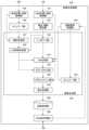
図4は、本実施の形態に係る画像生成装置200の機能構成図である。同図は機能に着目したブロック図を描いており、これらの機能ブロックはハードウエアのみ、ソフトウエアのみ、またはそれらの組合せによっていろいろな形で実現することができる。 FIG. 4 is a functional configuration diagram of the
画像生成装置200の少なくとも一部の機能をヘッドマウントディスプレイ100に実装してもよい。あるいは、画像生成装置200の少なくとも一部の機能を、ネットワークを介して画像生成装置200に接続されたサーバに実装してもよい。 At least part of the functions of the
HMD位置・姿勢取得部210は、ヘッドマウントディスプレイ100の現在の位置・姿勢情報をヘッドマウントディスプレイ100から取得する。HMD位置・姿勢取得部210は、ヘッドマウントディスプレイ100の姿勢センサ64などの慣性計測ユニット(IMU(Inertial Measurement Unit))から、ヘッドマウントディスプレイ100の現在の姿勢情報を示すIMUデータを取得し、カメラ画像およびIMUデータを用いて、自己位置推定と環境地図作成を同時に行うSLAM(Simultaneous Localization and Mapping)処理を実行し、ヘッドマウントディスプレイ100を装着したユーザの姿勢を推定してもよい。 The HMD position/
視点・視線設定部220は、HMD位置・姿勢取得部210により取得されたヘッドマウントディスプレイ100の位置・姿勢情報を用いて、ユーザの視点位置および視線方向を設定する。 The viewpoint/line-of-
身体位置・姿勢取得部244は、ユーザの身体部位の位置・姿勢を取得し、タイムワープ部246と接触判定部247に供給する。ある実施例では、身体位置・姿勢取得部244は、トラッカ500が検出する身体部位の位置・姿勢を取得する。別の実施例では、身体位置・姿勢取得部244は、撮影画像において身体部位を画像認識することによって、身体部位の位置・姿勢を取得する。 The body position/
タイムワープ部246は、トラッカ500の位置・姿勢取得時点のタイムスタンプと、ヘッドマウントディスプレイ100の位置・姿勢推定時点のタイムスタンプの差分にもとづいて、身体部位の位置・姿勢を、ヘッドマウントディスプレイ100の位置・姿勢推定時点のタイムスタンプに合うように変換する。 The
HDMI送受信部280は、ヘッドマウントディスプレイ100からカメラユニット80により撮影された現実空間の映像を受信し、画像信号処理部250に供給する。 The HDMI transmitting/receiving
画像信号処理部250は、ヘッドマウントディスプレイ100のカメラユニット80により撮影されたRaw画像に対してRGB変換(デモザイク処理)、ホワイトバランス、色補正、ノイズリダクションなどの画像信号処理(ISP(Image Signal Processing))を施し、さらにカメラユニット80の光学系による歪みなどを取り除く歪み補正処理を施す。画像信号処理部250は画像信号処理および歪み補正処理が施されたRGB画像を画像生成部230に供給する。 The image
画像生成部230は、画像記憶部260からコンピュータグラフィックスの生成に必要なデータを読み出し、仮想空間のオブジェクトをレンダリングしてCG画像を生成し、画像信号処理部250から提供される現実空間のカメラ画像に重畳するまたはカメラ画像に代えて描画することで拡張現実画像を生成し、画像記憶部260に出力する。 The
画像生成部230は、接触判定部247と、AR領域判定部248と、レンダリング部232と、AR生成部234と、ポストプロセス部236と、タイムワープ部238と、リプロジェクション部240と、歪み処理部242とを含む。 The
接触判定部247は、ユーザの身体部位と現実世界の物体の接触の有無を判定する。身体部位の位置・姿勢と現実世界の物体の形状情報・奥行き情報を比較することにより、接触判定を行うことができる。接触条件を満たした場合、接触判定部247は、身体部位が接触した現実世界の物体の箇所をAR領域判定部248に通知する。 The
現実世界の物体の形状情報や奥行き情報は、現実世界の空間を3Dスキャンすることで得られる。たとえば、赤外線パターン、Structured Light、TOF(Time Of Flight)などの方式のデプスセンサを用いて現実空間の奥行き情報を取得したり、ステレオカメラの視差情報から現実空間の奥行き情報を取得することができる。 Shape information and depth information of objects in the real world can be obtained by 3D scanning the space in the real world. For example, the depth information of the real space can be obtained using depth sensors such as infrared pattern, structured light, and TOF (Time Of Flight), or the depth information of the real space can be obtained from the parallax information of a stereo camera.
AR領域判定部248は、視点・視線設定部220からユーザの視点位置および視線方向を取得し、接触判定部247から身体部位が接触した現実世界の物体の箇所を示す情報を取得する。AR領域判定部248は、身体部位が接触した現実世界の物体の箇所を少なくとも含む部分空間をユーザの視点位置および視線方向から見た場合の領域をAR領域として判定し、AR領域を示す情報をAR生成部234とポストプロセス部236に供給する。 The AR
AR領域判定部248は、身体部位が接触した現実世界の物体の箇所を含む一定の部分空間をユーザの視点位置および視線方向から見た場合の領域をAR領域として判定する。接触箇所を含む部分空間として、接触箇所から所定の距離範囲の部分空間を選択してもよく、接触した物体の面全体を部分空間としてもよい。この部分空間に対するユーザの視点位置および視線方向によって、AR領域の位置や大きさが変化する。 The AR
レンダリング部232は、視点・視線設定部220によって設定されたユーザの視点位置および視線方向にしたがって、ヘッドマウントディスプレイ100を装着したユーザの視点位置から視線方向に見える仮想空間のオブジェクトをレンダリングし、AR生成部234に与える。 The
また、レンダリング部232は、カメラ映像に写り込んだユーザの手などの身体部位にエフェクトを施したり、当該身体部位を仮想モデルに置き換えてもよい。 In addition, the
AR生成部234は、画像信号処理部250から供給されるカメラ画像の内、AR領域判定部248によって指定されたAR領域にレンダリング部232により生成されたCG画像をカメラ画像に重畳するまたはカメラ画像に代えて描画することで拡張現実画像を生成し、ポストプロセス部236に与える。 The
ポストプロセス部236は、拡張現実画像に対して、被写界深度調整、トーンマッピング、アンチエイリアシングなどのポストプロセスを施し、現実空間の画像に仮想オブジェクトが重畳された拡張現実画像が自然で滑らかに見えるように後処理する。また、ポストプロセス部236は、AR領域判定部248によって指定されたAR領域に各種のエフェクトを施してもよい。AR生成部234がAR領域内にCG画像を重畳または置き換え描画することなく、ポストプロセス部236がAR領域内のカメラ画像に単にエフェクトを施すだけでもよい。 The
リプロジェクション部240は、HMD位置・姿勢取得部210からヘッドマウントディスプレイ100の最新の位置・姿勢情報を受け取り、ポストプロセスが施された拡張現実画像に対してリプロジェクション処理を施し、ヘッドマウントディスプレイ100の最新の視点位置・視線方向から見える画像に変換する。 The
ここで、リプロジェクションについて説明する。ヘッドマウントディスプレイ100にヘッドトラッキング機能をもたせて、ユーザの頭部の動きと連動して視点や視線方向を変えて仮想現実の映像を生成した場合、仮想現実の映像の生成から表示までに遅延があるため、映像生成時に前提としたユーザの頭部の向きと、映像をヘッドマウントディスプレイ100に表示した時点でのユーザの頭部の向きとの間でずれが発生し、ユーザは酔ったような感覚(「VR酔い(Virtual Reality Sickness)」などと呼ばれる)に陥ることがある。 Here, reprojection will be described. When the head-mounted
このように、ヘッドマウントディスプレイ100の動きを検知し、CPUが描画コマンドを発行し、GPU(Graphics Processing Unit)がレンダリングを実行し、描画された画像がヘッドマウントディスプレイ100に出力されるまでには時間がかかる。描画がたとえば60fps(フレーム/秒)のフレームレートで行われており、ヘッドマウントディスプレイ100の動きを検知してから画像を出力するまでに1フレーム分の遅れが生じるとする。これはフレームレート60fpsのもとでは、16.67ミリ秒ほどであり、人間がずれを感知するには十分な時間である。 In this way, the movement of the head mounted
そこで、「タイムワープ」または「リプロジェクション」と呼ばれる処理を行い、レンダリングした画像をヘッドマウントディスプレイ100の最新の位置と姿勢に合わせて補正することで人間がずれを感知しにくいようにする。 Therefore, a process called "time warp" or "reprojection" is performed to correct the rendered image according to the latest position and orientation of the head mounted
歪み処理部242は、リプロジェクション処理が施された拡張現実画像に対してヘッドマウントディスプレイ100の光学系で生じる歪みに合わせて画像を変形(distortion)させて歪ませる処理を施し、画像記憶部260に記憶する。 The
HDMI送受信部280は、画像記憶部260から画像生成部230により生成された拡張現実画像のフレームデータを読み出し、HDMIにしたがってヘッドマウントディスプレイ100に伝送する。 The HDMI transmission/
タイムワープ部238は、カメラの撮影時点のタイムスタンプと、ヘッドマウントディスプレイ100の位置・姿勢取得時点のタイムスタンプの差分にもとづいて、画像信号処理部250から供給されるカメラ画像をヘッドマウントディスプレイ100の位置・姿勢取得時点のタイムスタンプに合うように変換し、AR生成部234に与える。このタイムワープ処理は画像認識によって身体部位の位置および姿勢を検出する場合に特に有効である。AR生成部234は、タイムワープ処理されたカメラ画像にレンダリング部232により生成されたCG画像を重畳または置き換え描画することで拡張現実画像を生成し、ポストプロセス部236に与える。 The
図5Aおよび図5Bは、本実施の形態の画像生成装置200による拡張現実画像生成の例を説明する図である。 5A and 5B are diagrams for explaining an example of augmented reality image generation by the
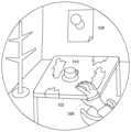
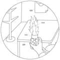
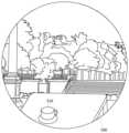
図5Aは、ヘッドマウントディスプレイ100のディスプレイパネル32に表示される画面を説明する図である。ここでヘッドマウントディスプレイ100はビデオ透過型であり、ヘッドマウントディスプレイ100に搭載されたカメラにより撮影された外界の映像が表示されている。 FIG. 5A is a diagram illustrating a screen displayed on the
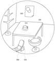
外界の映像からわかるように、ユーザは部屋の中におり、自分の前にテーブル530と椅子があり、テーブル530の上にはコーヒーカップ510が置かれている。壁際には洋服スタンドがある。また正面の壁にポスター520が貼られている。 As can be seen from the image of the outside world, the user is in a room with a table 530 and a chair in front of him and a
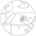
図5Bは、ユーザの手が図5Aのテーブル530に触れたときにディスプレイパネル32に表示される画面である。ユーザの手が図5Aのテーブル530の上面に接触すると、その接触箇所を含むテーブル530の表面全体が部分空間として指定され、その部分空間をユーザの視点から見た領域がAR領域となる。ここではAR領域であるテーブル530の表面にCGのテクスチャが貼り付けられ、画面では図5Bに示すようなARテーブル532に変化する。画面のそれ以外の領域はカメラ画像のままである。 FIG. 5B is a screen displayed on
このように、ユーザの身体部位が接触した現実空間の箇所を含む部分空間だけが画面上で拡張現実画像となることから、カメラ画像から拡張現実画像へ移行する際の非連続感や違和感が軽減され、また、ユーザは身体的臨場感をもつことができる。 In this way, only the partial space that includes the part of the real space where the user's body part is in contact becomes an augmented reality image on the screen, reducing the sense of discontinuity and discomfort when transitioning from the camera image to the augmented reality image. Also, the user can have a sense of physical presence.
現実空間の物体と接触するのはユーザの身体部位そのものには限定されない。ゲームで利用する銃、剣、杖、盾などの仮想オブジェクトをユーザが手にして、仮想オブジェクトが接触する現実空間の物体の箇所を含む部分空間を視点から見た場合のAR領域を決定してもよい。 It is not limited to the user's body part itself that comes into contact with an object in the real space. A user holds a virtual object such as a gun, a sword, a cane, or a shield used in a game, and determines an AR area when the subspace including the part of the object in the real space with which the virtual object comes into contact is viewed from the viewpoint. good too.
図6A~図6Cは、本実施の形態の画像生成装置200による拡張現実画像生成の別の例を説明する図である。 6A to 6C are diagrams for explaining another example of augmented reality image generation by the
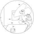
図6Aは、テーブル530上のコーヒーカップ510にユーザが手を伸ばしてコーヒーカップ510を取ろうとしている様子を示す。ユーザの手はまだコーヒーカップ510には触れていないため、画面には現実世界のコーヒーカップ510がそのまま見えている。 FIG. 6A shows a user reaching for a
図6Bは、ユーザの手が図6Aのコーヒーカップ510に触れたときの画面例を示す。ユーザの手がコーヒーカップ510に接触したことにより、コーヒーカップ510全体が部分空間として指定され、コーヒーカップ510をユーザの視点から見た領域がAR領域となる。AR生成部234は、コーヒーカップ510を仮想オブジェクト512に置き換えて描画する。 FIG. 6B shows an example screen when the user's hand touches the
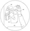
図6Cは、ユーザが仮想オブジェクト512を持ち上げたときの画面例を示す。ユーザは現実にはコーヒーカップ510を持ち上げているが、画面上では仮想オブジェクト512を持ち上げているように見える。また、仮想オブジェクト512にはエフェクトが加わり、この例では仮想オブジェクト512から炎514が飛び出している。 FIG. 6C shows an example screen when the user lifts the
上記の例では、AR領域をCG画像にすることでAR効果を与えたが、AR領域内は、視覚エフェクトのフィルタを適用したビデオシースルー画像を表示してもよい。あるいは、AR領域内は、完全なVR画像または実世界の構造を活かしたVR画像を表示してもよい。 In the above example, the AR area is a CG image to give an AR effect, but a video see-through image to which a visual effect filter is applied may be displayed within the AR area. Alternatively, the AR area may display a complete VR image or a VR image that takes advantage of real-world structures.
エフェクトについてもいろいろなバリエーションが考えられる。パーティクルの生成、視覚効果フィルタの適用、輝度や色の変更、レンズ効果、拡大・縮小表示、効果音の生成、バックグラウンドミュージックや効果音の音量の変化などがある。 Various variations of the effect are also conceivable. These include generating particles, applying visual effect filters, changing brightness and colors, lens effects, zooming in and out, generating sound effects, and changing the volume of background music and sound effects.
また、ボディトラッキングの技術を用いてユーザの身体の位置・姿勢を推定し、カメラ画像に写り込んだユーザの身体を別の仮想モデルに置き換えたり、カメラ画像に写り込んだユーザの身体からたとえば光が出ているようなエフェクトを加えてもよい。 In addition, body tracking technology is used to estimate the position and posture of the user's body, and the user's body captured in the camera image can be replaced with another virtual model. You can also add an effect that looks like a .
図7A~図7Cは、本実施の形態の画像生成装置200による拡張現実画像生成のさらに別の例を説明する図である。 7A to 7C are diagrams explaining still another example of augmented reality image generation by the
ユーザは図5Aで説明した部屋の中にいるが、部屋の外には図7Aに示すような仮想空間が存在する。ここでは仮想空間において一匹の恐竜が二本の木に側に立っている。 The user is in the room described in FIG. 5A, but outside the room there is a virtual space as shown in FIG. 7A. Here, in virtual space, one dinosaur is standing next to two trees.
図7Bに示すように、ユーザの手が部屋の正面の壁に触れると、手が触れた壁の箇所540がAR領域となり、手が触れた箇所540に穴が空いたように見え、部屋の外の仮想空間が描画される。ここでは、壁の穴に図7Aの仮想空間の恐竜の姿が見えている。 As shown in FIG. 7B, when the user's hand touches the front wall of the room, the
図7Cに示すように、ユーザの手が壁の別の箇所542を触れると、手が触れた壁の別の箇所542がAR領域となり、穴が空き、そこから仮想空間を覗き見ることができる。ここでは、壁の穴に図7Aの仮想空間の木の一部が見えている。 As shown in FIG. 7C, when the user's hand touches another
このように、ユーザの身体部位が接触した箇所以外では現実空間のシースルー映像が見えているが、身体部位が接触した箇所では現実世界の向こう側にある外部の仮想世界が見える。 In this way, a see-through image of the real space can be seen at locations other than where the user's body part is in contact, but the external virtual world beyond the real world can be seen at the location where the user's body part is in contact.
ユーザが手で触れた箇所を鏡面にしてユーザの現実の姿やユーザの身体を仮想的に表すキャラクタを鏡面に描画してもよい。これにより、ユーザが手で触れた箇所だけを仮想的な鏡にすることができる。 A part touched by the user's hand may be mirrored, and a character representing the user's actual appearance or the user's body may be drawn on the mirrored surface. As a result, only the portion touched by the user's hand can be made into a virtual mirror.
図8Aおよび図8Bは、本実施の形態の画像生成装置200による拡張現実画像生成のさらに別の例を説明する図である。 8A and 8B are diagrams illustrating still another example of augmented reality image generation by the
図8Aは、ユーザが両手を叩いたときの画面例を示す。ユーザは両手にトラッカ500を装着しており、右手のトラッカ500が検出する右手の位置と左手のトラッカ500が検出する左手の位置が所定の距離以下まで近づいたときに、接触判定部247は、両手が接触したと判定し、両手が接触した位置にエフェクト550が加わり、両手が接触した位置から仮想オブジェクト552が飛び出す。このようにAR領域判定部248は、ユーザの身体部位同士が接触した領域をAR領域に決定し、AR生成部234がAR領域に仮想現実画像を生成してもよい。 FIG. 8A shows an example screen when the user clapped both hands. The user wears the
図8Bは、ユーザが足で床を叩いたときの画面例を示す。ユーザは足首にトラッカ500を装着しており、接触判定部247は、トラッカ500が検出する足の位置と床の位置の間の距離によって足が床に接触しているかどうかを判定し、足が床を叩いたことを検出する。足が床を叩いたとき、足が叩いた床の箇所がAR領域となり、エフェクト554が加わる。 FIG. 8B shows an example of the screen when the user hits the floor with his/her foot. The user wears the
図8Aおよび図8Bにおいて、映像によるエフェクトと同時に、あるいは映像によるエフェクトに代えて、サウンドによるエフェクトを加えてもよい。 In FIGS. 8A and 8B, a sound effect may be added simultaneously with the video effect or instead of the video effect.
図9は、本実施の形態の画像生成装置200による拡張現実画像生成のさらに別の例を説明する図である。 FIG. 9 is a diagram illustrating still another example of augmented reality image generation by the
図9は、ユーザが手にした仮想オブジェクトである剣560が図5Aのコーヒーカップ510に接触したときの画面例を示す。ユーザの手に装着されたトラッカ500が検出するユーザの手の位置情報をオフセットすることでユーザが手にした仮想的な剣560の位置を計算することできる。接触判定部247は、剣560の位置とコーヒーカップ510の位置が所定の距離以内まで近づいたとき、剣560がコーヒーカップ510に接触したと判定し、AR領域判定部248は、剣が接触したコーヒーカップ510をAR領域と判定する。AR生成部234は、コーヒーカップ510の領域に二つに割れた仮想的なコーヒーカップ514の画像を重畳する。 FIG. 9 shows an example screen when a
図10Aおよび図10Bは、本実施の形態の画像生成装置200による拡張現実画像生成のさらに別の例を説明する図である。 10A and 10B are diagrams illustrating still another example of augmented reality image generation by the
図10Aに示すように、ユーザが手で部屋の壁を叩くと、壁全体がAR領域となり、現実世界の壁の形状に合わせて生成された仮想的なブロック塀がCGで部屋の壁全体に描画される。また、ユーザの手が触れた壁の箇所にはブロック塀が壊れて穴が空いたような画像が描画される。 As shown in FIG. 10A, when the user hits the wall of the room with his/her hand, the entire wall becomes an AR area, and a virtual block wall generated according to the shape of the wall in the real world is created by CG on the entire wall of the room. drawn. Also, an image that looks like a broken block wall and a hole is drawn on the part of the wall touched by the user's hand.
ユーザが壁をさらに押したり叩いたりすると、図10Bに示すように、仮想的なブロック塀が部屋の壁の向こう側に倒れて、壁の向こう側にある仮想世界が表示されるような仮想的な演出を加えることもできる。 If the user pushes or hits the wall further, the virtual block wall collapses over the wall of the room to display the virtual world beyond the wall, as shown in FIG. 10B. You can also add special effects.
以上述べたように、本実施の形態の画像生成装置200によれば、ユーザの身体部位が接触した現実空間の箇所を拡張現実画像が生成されるAR領域として指定することができる。ユーザは身体部位を自由に動かして現実空間に触れることにより、AR領域を自由に指定することができる。これにより、カメラ画像に突如としてAR効果が加わるのではなく、ユーザの身体部位が接触した領域にAR効果が加わるので、現実映像から拡張現実映像へ移行する際の違和感が軽減するとともに、身体的な臨場感をもつことができる。 As described above, according to the
以上、本発明を実施の形態をもとに説明した。実施の形態は例示であり、それらの各構成要素や各処理プロセスの組合せにいろいろな変形例が可能なこと、またそうした変形例も本発明の範囲にあることは当業者に理解されるところである。 The present invention has been described above based on the embodiments. It should be understood by those skilled in the art that the embodiments are examples, and that various modifications can be made to combinations of each component and each treatment process, and that such modifications are within the scope of the present invention. .
10 制御部、 20 入力インタフェース、 30 出力インタフェース、 32 ディスプレイパネル、 40 通信制御部、 42 ネットワークアダプタ、 44 アンテナ、 50 記憶部、 64 姿勢センサ、 70 外部入出力端子インタフェース、 72 外部メモリ、 80 カメラユニット、 100 ヘッドマウントディスプレイ、 200 画像生成装置、 210 HMD位置・姿勢取得部、 220 視点・視線設定部、 230 画像生成部、 232 レンダリング部、 234 AR生成部、 236 ポストプロセス部、 238 タイムワープ部、 240 リプロジェクション部、 242 歪み処理部、 244 身体位置・姿勢取得部、 246 タイムワープ部、 247 接触判定部、 248 AR領域判定部、 250 画像信号処理部、 260 画像記憶部、 280 HDMI送受信部、 300 インタフェース、 500 トラッカ。 10
この発明は、画像生成技術に利用できる。 INDUSTRIAL APPLICABILITY The present invention can be used in image generation technology.
Claims (9)
Translated fromJapanese前記身体部位の位置をオフセットすることにより計算される前記身体部位が有する仮想オブジェクトの位置および前記身体部位の姿勢にもとづいて、前記身体部位が有する前記仮想オブジェクトと現実世界の物体の接触の有無を判定する接触判定部と、
前記身体部位が有する前記仮想オブジェクトが接触した前記現実世界の物体の箇所を含む部分空間を前記ユーザの視点から見た場合の領域を拡張現実領域として判定する拡張現実領域判定部と、
前記現実世界の撮影画像の内、前記拡張現実領域に拡張現実画像を生成する拡張現実生成部とを含み、
前記拡張現実生成部は、前記拡張現実領域に前記ユーザの現実の姿または前記ユーザの身体を仮想的に表すキャラクタを描画することにより、前記拡張現実領域に拡張現実画像を生成することを特徴とする画像生成装置。an acquisition unit that acquires the position and posture of a user's body part;
Presence or absence of contact between the virtual object of the body part and an object in the real world is determined based on the positionof the virtual objectof the body part and the orientation of the body part calculated by offsetting the position of the body part. a contact determination unit that determines;
an augmentedreality area determination unit that determines, as an augmented reality area, a partial space including a portion of the real-world object that the virtual object of the body part is in contact with, viewed from the viewpoint of the user;
an augmented reality generation unit that generates an augmented reality image in the augmented reality area from the captured image of the real world,
The augmented reality generation unit generates an augmented reality image in the augmented reality area by drawing a character that virtually represents the user's actual appearance or the user's body in the augmented reality area. image generation device.
前記身体部位の位置をオフセットすることにより計算される前記身体部位が有する仮想オブジェクトの位置および前記身体部位の姿勢にもとづいて、前記身体部位が有する前記仮想オブジェクトと現実世界の物体の接触の有無を判定する接触判定ステップと、
前記身体部位が有する前記仮想オブジェクトが接触した前記現実世界の物体の箇所を含む部分空間を前記ユーザの視点から見た場合の領域を拡張現実領域として判定する拡張現実領域判定ステップと、
前記現実世界の撮影画像の内、前記拡張現実領域に拡張現実画像を生成する拡張現実生成ステップとを含み、
前記拡張現実生成ステップは、前記拡張現実領域に前記ユーザの現実の姿または前記ユーザの身体を仮想的に表すキャラクタを描画することにより、前記拡張現実領域に拡張現実画像を生成することを特徴とする画像生成方法。an obtaining step of obtaining positions and poses of body parts of a user;
Presence or absence of contact between the virtual object of the body part and an object in the real world is determined based on the positionof the virtual objectof the body part and the orientation of the body part calculated by offsetting the position of the body part. a contact determination step for determining;
an augmentedreality area determination step of determining, as an augmented reality area, a partial space including a portion of the real-world object that the virtual object of the body part is in contact with, viewed from the viewpoint of the user;
an augmented reality generation step of generating an augmented reality image in the augmented reality area from among the captured images of the real world;
The augmented reality generation step generates an augmented reality image in the augmented reality area by drawing a character that virtually represents the user's actual appearance or the user's body in the augmented reality area. image generation method.
前記身体部位の位置をオフセットすることにより計算される前記身体部位が有する仮想オブジェクトの位置および前記身体部位の姿勢にもとづいて、前記身体部位が有する前記仮想オブジェクトと現実世界の物体の接触の有無を判定する接触判定機能と、
前記身体部位が有する前記仮想オブジェクトが接触した前記現実世界の物体の箇所を含む部分空間を前記ユーザの視点から見た場合の領域を拡張現実領域として判定する拡張現実領域判定機能と、
前記現実世界の撮影画像の内、前記拡張現実領域に拡張現実画像を生成する拡張現実生成機能とをコンピュータに実現させ、
前記拡張現実生成機能は、前記拡張現実領域に前記ユーザの現実の姿または前記ユーザの身体を仮想的に表すキャラクタを描画することにより、前記拡張現実領域に拡張現実画像を生成することを特徴とするプログラム。an acquisition function for acquiring the position and posture of a user's body part;
Presence or absence of contact between the virtual object of the body part and an object in the real world is determined based on the positionof the virtual objectof the body part and the orientation of the body part calculated by offsetting the position of the body part. a contact determination function to determine,
an augmentedreality area determination function for determining, as an augmented reality area, a partial space including the location of the real-world object that the virtual object of the body part is in contact with, viewed from the viewpoint of the user;
causing a computer to implement an augmented reality generation function that generates an augmented reality image in the augmented reality area from among the captured images of the real world;
The augmented reality generation function is characterized in that an augmented reality image is generated in the augmented reality area by drawing a character that virtually represents the user's actual appearance or the user's body in the augmented reality area. program to do.
Priority Applications (1)
| Application Number | Priority Date | Filing Date | Title |
|---|---|---|---|
| JP2023116831AJP7496460B2 (en) | 2018-08-23 | 2023-07-18 | Image generating device and image generating method |
Applications Claiming Priority (1)
| Application Number | Priority Date | Filing Date | Title |
|---|---|---|---|
| PCT/JP2018/031252WO2020039568A1 (en) | 2018-08-23 | 2018-08-23 | Image generation device and image generation method |
Related Child Applications (1)
| Application Number | Title | Priority Date | Filing Date |
|---|---|---|---|
| JP2023116831ADivisionJP7496460B2 (en) | 2018-08-23 | 2023-07-18 | Image generating device and image generating method |
Publications (2)
| Publication Number | Publication Date |
|---|---|
| JPWO2020039568A1 JPWO2020039568A1 (en) | 2021-08-12 |
| JP7317024B2true JP7317024B2 (en) | 2023-07-28 |
Family
ID=69591999
Family Applications (2)
| Application Number | Title | Priority Date | Filing Date |
|---|---|---|---|
| JP2020537981AActiveJP7317024B2 (en) | 2018-08-23 | 2018-08-23 | Image generation device and image generation method |
| JP2023116831AActiveJP7496460B2 (en) | 2018-08-23 | 2023-07-18 | Image generating device and image generating method |
Family Applications After (1)
| Application Number | Title | Priority Date | Filing Date |
|---|---|---|---|
| JP2023116831AActiveJP7496460B2 (en) | 2018-08-23 | 2023-07-18 | Image generating device and image generating method |
Country Status (3)
| Country | Link |
|---|---|
| US (1) | US11373379B2 (en) |
| JP (2) | JP7317024B2 (en) |
| WO (1) | WO2020039568A1 (en) |
Families Citing this family (10)
| Publication number | Priority date | Publication date | Assignee | Title |
|---|---|---|---|---|
| CN112639686B (en) | 2018-09-07 | 2024-10-11 | 苹果公司 | Transition between the images and sounds of a virtual environment and those of a real environment |
| CN113287304A (en)* | 2019-01-22 | 2021-08-20 | 索尼集团公司 | Information processing apparatus and method |
| US12147607B1 (en)* | 2019-07-11 | 2024-11-19 | Apple Inc. | Transitioning between environments |
| US11096006B1 (en)* | 2019-11-04 | 2021-08-17 | Facebook Technologies, Llc | Dynamic speech directivity reproduction |
| CN114820835A (en) | 2021-01-28 | 2022-07-29 | 索尼半导体解决方案公司 | Information processing method, information processing apparatus, and non-volatile storage medium |
| CN114827434A (en)* | 2021-01-28 | 2022-07-29 | 索尼半导体解决方案公司 | Information processing method, information processing apparatus, and non-volatile storage medium |
| US12229977B2 (en)* | 2021-05-18 | 2025-02-18 | Snap Inc. | Augmented reality guided depth estimation |
| TWI800163B (en) | 2021-12-16 | 2023-04-21 | 許紓琬 | Smart interactive augmented reality hand fine motor rehabilitation system |
| JP2023125554A (en)* | 2022-02-28 | 2023-09-07 | 株式会社Jvcケンウッド | Virtual-space image display device, virtual-space image display method, and virtual-space image display program |
| JP2023156940A (en)* | 2022-04-13 | 2023-10-25 | キヤノン株式会社 | Image processing device, image processing method and program |
Citations (11)
| Publication number | Priority date | Publication date | Assignee | Title |
|---|---|---|---|---|
| JP2011008350A (en) | 2009-06-23 | 2011-01-13 | Canon Inc | Image processing method and image processing apparatus |
| JP2012088776A (en) | 2010-10-15 | 2012-05-10 | Nintendo Co Ltd | Image processing program, apparatus, system, and method |
| JP2013520729A (en) | 2010-02-22 | 2013-06-06 | ナイキ インターナショナル リミテッド | Augmented reality design system |
| JP2015203889A (en) | 2014-04-10 | 2015-11-16 | キヤノン株式会社 | Information processing terminal, information processing method, and computer program |
| JP2015228256A (en) | 2011-03-29 | 2015-12-17 | クアルコム,インコーポレイテッド | System for rendering of shared digital interfaces relative to each user's point of view |
| JP2016045815A (en) | 2014-08-26 | 2016-04-04 | 泰章 岩井 | Virtual reality presentation system, virtual reality presentation device, and virtual reality presentation method |
| JP2016192137A (en) | 2015-03-31 | 2016-11-10 | ソニー株式会社 | Information processing device, information processing method and program |
| US20180095616A1 (en) | 2016-10-04 | 2018-04-05 | Facebook, Inc. | Controls and Interfaces for User Interactions in Virtual Spaces |
| US20180108179A1 (en) | 2016-10-17 | 2018-04-19 | Microsoft Technology Licensing, Llc | Generating and Displaying a Computer Generated Image on a Future Pose of a Real World Object |
| JP2018109835A (en) | 2016-12-28 | 2018-07-12 | 株式会社バンダイナムコエンターテインメント | Simulation system and its program |
| JP2019536131A (en) | 2016-10-04 | 2019-12-12 | フェイスブック,インク. | Controls and interfaces for user interaction in virtual space |
Family Cites Families (10)
| Publication number | Priority date | Publication date | Assignee | Title |
|---|---|---|---|---|
| US9505497B2 (en)* | 2011-08-10 | 2016-11-29 | Honeywell International Inc. | Systems and methods for a virtual terrain display |
| US9417692B2 (en)* | 2012-06-29 | 2016-08-16 | Microsoft Technology Licensing, Llc | Deep augmented reality tags for mixed reality |
| US9761045B1 (en)* | 2013-03-15 | 2017-09-12 | Bentley Systems, Incorporated | Dynamic and selective model clipping for enhanced augmented hypermodel visualization |
| JP6618681B2 (en)* | 2013-12-25 | 2019-12-11 | キヤノンマーケティングジャパン株式会社 | Information processing apparatus, control method and program therefor, and information processing system |
| GB2534580B (en)* | 2015-01-28 | 2020-06-17 | Sony Interactive Entertainment Europe Ltd | Image processing |
| CN105988578B (en)* | 2015-03-04 | 2019-06-21 | 华为技术有限公司 | A method, device and system for interactive video display |
| GB2548154A (en)* | 2016-03-11 | 2017-09-13 | Sony Computer Entertainment Europe Ltd | Virtual reality |
| JP6058855B1 (en)* | 2016-07-07 | 2017-01-11 | 株式会社コロプラ | Information processing method and program for causing computer to execute information processing method |
| CA3034384A1 (en)* | 2016-08-22 | 2018-03-01 | Magic Leap, Inc. | Virtual, augmented, and mixed reality systems and methods |
| US10255729B1 (en)* | 2018-05-29 | 2019-04-09 | Exploring, Inc. | System and method for haptic mapping of a configurable virtual reality environment |
- 2018
- 2018-08-23JPJP2020537981Apatent/JP7317024B2/enactiveActive
- 2018-08-23WOPCT/JP2018/031252patent/WO2020039568A1/ennot_activeCeased
- 2018-08-23USUS17/268,857patent/US11373379B2/enactiveActive
- 2023
- 2023-07-18JPJP2023116831Apatent/JP7496460B2/enactiveActive
Patent Citations (11)
| Publication number | Priority date | Publication date | Assignee | Title |
|---|---|---|---|---|
| JP2011008350A (en) | 2009-06-23 | 2011-01-13 | Canon Inc | Image processing method and image processing apparatus |
| JP2013520729A (en) | 2010-02-22 | 2013-06-06 | ナイキ インターナショナル リミテッド | Augmented reality design system |
| JP2012088776A (en) | 2010-10-15 | 2012-05-10 | Nintendo Co Ltd | Image processing program, apparatus, system, and method |
| JP2015228256A (en) | 2011-03-29 | 2015-12-17 | クアルコム,インコーポレイテッド | System for rendering of shared digital interfaces relative to each user's point of view |
| JP2015203889A (en) | 2014-04-10 | 2015-11-16 | キヤノン株式会社 | Information processing terminal, information processing method, and computer program |
| JP2016045815A (en) | 2014-08-26 | 2016-04-04 | 泰章 岩井 | Virtual reality presentation system, virtual reality presentation device, and virtual reality presentation method |
| JP2016192137A (en) | 2015-03-31 | 2016-11-10 | ソニー株式会社 | Information processing device, information processing method and program |
| US20180095616A1 (en) | 2016-10-04 | 2018-04-05 | Facebook, Inc. | Controls and Interfaces for User Interactions in Virtual Spaces |
| JP2019536131A (en) | 2016-10-04 | 2019-12-12 | フェイスブック,インク. | Controls and interfaces for user interaction in virtual space |
| US20180108179A1 (en) | 2016-10-17 | 2018-04-19 | Microsoft Technology Licensing, Llc | Generating and Displaying a Computer Generated Image on a Future Pose of a Real World Object |
| JP2018109835A (en) | 2016-12-28 | 2018-07-12 | 株式会社バンダイナムコエンターテインメント | Simulation system and its program |
Also Published As
| Publication number | Publication date |
|---|---|
| JPWO2020039568A1 (en) | 2021-08-12 |
| US11373379B2 (en) | 2022-06-28 |
| WO2020039568A1 (en) | 2020-02-27 |
| JP7496460B2 (en) | 2024-06-06 |
| JP2023139098A (en) | 2023-10-03 |
| US20210174601A1 (en) | 2021-06-10 |
Similar Documents
| Publication | Publication Date | Title |
|---|---|---|
| JP7317024B2 (en) | Image generation device and image generation method | |
| US10559110B2 (en) | Virtual reality | |
| JP6732716B2 (en) | Image generation apparatus, image generation system, image generation method, and program | |
| CN110413105A (en) | The tangible visualization of virtual objects in virtual environment | |
| JPWO2020026419A1 (en) | Image generator and image generation method | |
| JP6978289B2 (en) | Image generator, head-mounted display, image generation system, image generation method, and program | |
| JP6711803B2 (en) | Image generating apparatus and image generating method | |
| JP2011258159A (en) | Program, information storage medium and image generation system | |
| US11003408B2 (en) | Image generating apparatus and image generating method | |
| JP7349256B2 (en) | Image generation device and information presentation method | |
| JP2020064592A (en) | Image generator, image generation system, image generation method, and program | |
| WO2022107688A1 (en) | Image generating device, image generating method, and program | |
| JP2024031113A (en) | Information processing device and image generation method | |
| WO2022255058A1 (en) | Information processing device and image generation method | |
| WO2024042929A1 (en) | Information processing device and image generation method |
Legal Events
| Date | Code | Title | Description |
|---|---|---|---|
| A524 | Written submission of copy of amendment under article 19 pct | Free format text:JAPANESE INTERMEDIATE CODE: A527 Effective date:20201022 | |
| A621 | Written request for application examination | Free format text:JAPANESE INTERMEDIATE CODE: A621 Effective date:20210811 | |
| A131 | Notification of reasons for refusal | Free format text:JAPANESE INTERMEDIATE CODE: A131 Effective date:20220726 | |
| A521 | Request for written amendment filed | Free format text:JAPANESE INTERMEDIATE CODE: A523 Effective date:20220920 | |
| A131 | Notification of reasons for refusal | Free format text:JAPANESE INTERMEDIATE CODE: A131 Effective date:20230117 | |
| A521 | Request for written amendment filed | Free format text:JAPANESE INTERMEDIATE CODE: A523 Effective date:20230308 | |
| TRDD | Decision of grant or rejection written | ||
| A01 | Written decision to grant a patent or to grant a registration (utility model) | Free format text:JAPANESE INTERMEDIATE CODE: A01 Effective date:20230627 | |
| A61 | First payment of annual fees (during grant procedure) | Free format text:JAPANESE INTERMEDIATE CODE: A61 Effective date:20230718 | |
| R150 | Certificate of patent or registration of utility model | Ref document number:7317024 Country of ref document:JP Free format text:JAPANESE INTERMEDIATE CODE: R150 |