JP7316791B2 - Monolithic visible wavelength fiber laser - Google Patents
Monolithic visible wavelength fiber laserDownload PDFInfo
- Publication number
- JP7316791B2 JP7316791B2JP2018556805AJP2018556805AJP7316791B2JP 7316791 B2JP7316791 B2JP 7316791B2JP 2018556805 AJP2018556805 AJP 2018556805AJP 2018556805 AJP2018556805 AJP 2018556805AJP 7316791 B2JP7316791 B2JP 7316791B2
- Authority
- JP
- Japan
- Prior art keywords
- fiber
- bragg grating
- laser
- core
- optical fiber
- Prior art date
- Legal status (The legal status is an assumption and is not a legal conclusion. Google has not performed a legal analysis and makes no representation as to the accuracy of the status listed.)
- Active
Links
- 239000000835fiberSubstances0.000titleclaimsdescription228
- 238000001069Raman spectroscopyMethods0.000claimsdescription130
- 239000013307optical fiberSubstances0.000claimsdescription112
- 238000005253claddingMethods0.000claimsdescription59
- 230000008713feedback mechanismEffects0.000claimsdescription28
- 238000001228spectrumMethods0.000claimsdescription19
- 239000002019doping agentSubstances0.000claimsdescription13
- 230000001902propagating effectEffects0.000claimsdescription7
- BHEPBYXIRTUNPN-UHFFFAOYSA-Nhydridophosphorus(.) (triplet)Chemical compound[PH]BHEPBYXIRTUNPN-UHFFFAOYSA-N0.000claims1
- 238000000576coating methodMethods0.000description35
- 238000000034methodMethods0.000description29
- 239000011248coating agentSubstances0.000description25
- 239000011521glassSubstances0.000description22
- 230000003287optical effectEffects0.000description15
- 238000010586diagramMethods0.000description6
- 239000000463materialSubstances0.000description6
- 230000000737periodic effectEffects0.000description6
- VYPSYNLAJGMNEJ-UHFFFAOYSA-NSilicium dioxideChemical groupO=[Si]=OVYPSYNLAJGMNEJ-UHFFFAOYSA-N0.000description5
- 230000000694effectsEffects0.000description4
- 230000003595spectral effectEffects0.000description4
- 230000005670electromagnetic radiationEffects0.000description3
- 238000004519manufacturing processMethods0.000description3
- 230000001629suppressionEffects0.000description3
- 230000009471actionEffects0.000description2
- 230000008901benefitEffects0.000description2
- 230000008859changeEffects0.000description2
- 238000006243chemical reactionMethods0.000description2
- 238000001816coolingMethods0.000description2
- 230000008878couplingEffects0.000description2
- 238000010168coupling processMethods0.000description2
- 238000005859coupling reactionMethods0.000description2
- 230000001419dependent effectEffects0.000description2
- 229910052732germaniumInorganic materials0.000description2
- GNPVGFCGXDBREM-UHFFFAOYSA-Ngermanium atomChemical compound[Ge]GNPVGFCGXDBREM-UHFFFAOYSA-N0.000description2
- 230000008569processEffects0.000description2
- 230000005855radiationEffects0.000description2
- 238000002310reflectometryMethods0.000description2
- OAICVXFJPJFONN-UHFFFAOYSA-NPhosphorusChemical group[P]OAICVXFJPJFONN-UHFFFAOYSA-N0.000description1
- 230000009286beneficial effectEffects0.000description1
- 239000013043chemical agentSubstances0.000description1
- 238000004891communicationMethods0.000description1
- 230000003750conditioning effectEffects0.000description1
- 230000003247decreasing effectEffects0.000description1
- 238000005516engineering processMethods0.000description1
- 238000010438heat treatmentMethods0.000description1
- 230000007246mechanismEffects0.000description1
- 230000004048modificationEffects0.000description1
- 238000012986modificationMethods0.000description1
- 229910052698phosphorusInorganic materials0.000description1
- 239000011574phosphorusSubstances0.000description1
- 238000001782photodegradationMethods0.000description1
- 239000004065semiconductorSubstances0.000description1
- 238000002211ultraviolet spectrumMethods0.000description1
- 238000001429visible spectrumMethods0.000description1
Images


Classifications
- G—PHYSICS
- G02—OPTICS
- G02B—OPTICAL ELEMENTS, SYSTEMS OR APPARATUS
- G02B6/00—Light guides; Structural details of arrangements comprising light guides and other optical elements, e.g. couplings
- G02B6/02—Optical fibres with cladding with or without a coating
- G02B6/02057—Optical fibres with cladding with or without a coating comprising gratings
- G02B6/02076—Refractive index modulation gratings, e.g. Bragg gratings
- G02B6/02123—Refractive index modulation gratings, e.g. Bragg gratings characterised by the method of manufacture of the grating
- G02B6/02128—Internal inscription, i.e. grating written by light propagating within the fibre, e.g. "self-induced"
- H—ELECTRICITY
- H01—ELECTRIC ELEMENTS
- H01S—DEVICES USING THE PROCESS OF LIGHT AMPLIFICATION BY STIMULATED EMISSION OF RADIATION [LASER] TO AMPLIFY OR GENERATE LIGHT; DEVICES USING STIMULATED EMISSION OF ELECTROMAGNETIC RADIATION IN WAVE RANGES OTHER THAN OPTICAL
- H01S3/00—Lasers, i.e. devices using stimulated emission of electromagnetic radiation in the infrared, visible or ultraviolet wave range
- H01S3/05—Construction or shape of optical resonators; Accommodation of active medium therein; Shape of active medium
- H01S3/06—Construction or shape of active medium
- H01S3/063—Waveguide lasers, i.e. whereby the dimensions of the waveguide are of the order of the light wavelength
- H01S3/067—Fibre lasers
- H01S3/0675—Resonators including a grating structure, e.g. distributed Bragg reflectors [DBR] or distributed feedback [DFB] fibre lasers
- G—PHYSICS
- G02—OPTICS
- G02B—OPTICAL ELEMENTS, SYSTEMS OR APPARATUS
- G02B6/00—Light guides; Structural details of arrangements comprising light guides and other optical elements, e.g. couplings
- G—PHYSICS
- G02—OPTICS
- G02B—OPTICAL ELEMENTS, SYSTEMS OR APPARATUS
- G02B6/00—Light guides; Structural details of arrangements comprising light guides and other optical elements, e.g. couplings
- G02B6/10—Light guides; Structural details of arrangements comprising light guides and other optical elements, e.g. couplings of the optical waveguide type
- G02B6/12—Light guides; Structural details of arrangements comprising light guides and other optical elements, e.g. couplings of the optical waveguide type of the integrated circuit kind
- G—PHYSICS
- G02—OPTICS
- G02B—OPTICAL ELEMENTS, SYSTEMS OR APPARATUS
- G02B6/00—Light guides; Structural details of arrangements comprising light guides and other optical elements, e.g. couplings
- G02B6/24—Coupling light guides
- G02B6/255—Splicing of light guides, e.g. by fusion or bonding
- G02B6/2551—Splicing of light guides, e.g. by fusion or bonding using thermal methods, e.g. fusion welding by arc discharge, laser beam, plasma torch
- G—PHYSICS
- G02—OPTICS
- G02B—OPTICAL ELEMENTS, SYSTEMS OR APPARATUS
- G02B6/00—Light guides; Structural details of arrangements comprising light guides and other optical elements, e.g. couplings
- G02B6/10—Light guides; Structural details of arrangements comprising light guides and other optical elements, e.g. couplings of the optical waveguide type
- G02B6/12—Light guides; Structural details of arrangements comprising light guides and other optical elements, e.g. couplings of the optical waveguide type of the integrated circuit kind
- G02B2006/12166—Manufacturing methods
- G02B2006/12169—Annealing
- G02B2006/12171—Annealing using a laser beam
- H—ELECTRICITY
- H01—ELECTRIC ELEMENTS
- H01S—DEVICES USING THE PROCESS OF LIGHT AMPLIFICATION BY STIMULATED EMISSION OF RADIATION [LASER] TO AMPLIFY OR GENERATE LIGHT; DEVICES USING STIMULATED EMISSION OF ELECTROMAGNETIC RADIATION IN WAVE RANGES OTHER THAN OPTICAL
- H01S3/00—Lasers, i.e. devices using stimulated emission of electromagnetic radiation in the infrared, visible or ultraviolet wave range
- H01S3/05—Construction or shape of optical resonators; Accommodation of active medium therein; Shape of active medium
- H01S3/06—Construction or shape of active medium
- H01S3/063—Waveguide lasers, i.e. whereby the dimensions of the waveguide are of the order of the light wavelength
- H01S3/067—Fibre lasers
- H01S3/06708—Constructional details of the fibre, e.g. compositions, cross-section, shape or tapering
- H—ELECTRICITY
- H01—ELECTRIC ELEMENTS
- H01S—DEVICES USING THE PROCESS OF LIGHT AMPLIFICATION BY STIMULATED EMISSION OF RADIATION [LASER] TO AMPLIFY OR GENERATE LIGHT; DEVICES USING STIMULATED EMISSION OF ELECTROMAGNETIC RADIATION IN WAVE RANGES OTHER THAN OPTICAL
- H01S3/00—Lasers, i.e. devices using stimulated emission of electromagnetic radiation in the infrared, visible or ultraviolet wave range
- H01S3/05—Construction or shape of optical resonators; Accommodation of active medium therein; Shape of active medium
- H01S3/08—Construction or shape of optical resonators or components thereof
- H01S3/08059—Constructional details of the reflector, e.g. shape
- H01S3/08063—Graded reflectivity, e.g. variable reflectivity mirror
- H—ELECTRICITY
- H01—ELECTRIC ELEMENTS
- H01S—DEVICES USING THE PROCESS OF LIGHT AMPLIFICATION BY STIMULATED EMISSION OF RADIATION [LASER] TO AMPLIFY OR GENERATE LIGHT; DEVICES USING STIMULATED EMISSION OF ELECTROMAGNETIC RADIATION IN WAVE RANGES OTHER THAN OPTICAL
- H01S3/00—Lasers, i.e. devices using stimulated emission of electromagnetic radiation in the infrared, visible or ultraviolet wave range
- H01S3/09—Processes or apparatus for excitation, e.g. pumping
- H01S3/091—Processes or apparatus for excitation, e.g. pumping using optical pumping
- H01S3/094—Processes or apparatus for excitation, e.g. pumping using optical pumping by coherent light
- H01S3/094003—Processes or apparatus for excitation, e.g. pumping using optical pumping by coherent light the pumped medium being a fibre
- H—ELECTRICITY
- H01—ELECTRIC ELEMENTS
- H01S—DEVICES USING THE PROCESS OF LIGHT AMPLIFICATION BY STIMULATED EMISSION OF RADIATION [LASER] TO AMPLIFY OR GENERATE LIGHT; DEVICES USING STIMULATED EMISSION OF ELECTROMAGNETIC RADIATION IN WAVE RANGES OTHER THAN OPTICAL
- H01S3/00—Lasers, i.e. devices using stimulated emission of electromagnetic radiation in the infrared, visible or ultraviolet wave range
- H01S3/09—Processes or apparatus for excitation, e.g. pumping
- H01S3/091—Processes or apparatus for excitation, e.g. pumping using optical pumping
- H01S3/094—Processes or apparatus for excitation, e.g. pumping using optical pumping by coherent light
- H01S3/0941—Processes or apparatus for excitation, e.g. pumping using optical pumping by coherent light of a laser diode
- H01S3/09415—Processes or apparatus for excitation, e.g. pumping using optical pumping by coherent light of a laser diode the pumping beam being parallel to the lasing mode of the pumped medium, e.g. end-pumping
- H—ELECTRICITY
- H01—ELECTRIC ELEMENTS
- H01S—DEVICES USING THE PROCESS OF LIGHT AMPLIFICATION BY STIMULATED EMISSION OF RADIATION [LASER] TO AMPLIFY OR GENERATE LIGHT; DEVICES USING STIMULATED EMISSION OF ELECTROMAGNETIC RADIATION IN WAVE RANGES OTHER THAN OPTICAL
- H01S3/00—Lasers, i.e. devices using stimulated emission of electromagnetic radiation in the infrared, visible or ultraviolet wave range
- H01S3/30—Lasers, i.e. devices using stimulated emission of electromagnetic radiation in the infrared, visible or ultraviolet wave range using scattering effects, e.g. stimulated Brillouin or Raman effects
- H01S3/302—Lasers, i.e. devices using stimulated emission of electromagnetic radiation in the infrared, visible or ultraviolet wave range using scattering effects, e.g. stimulated Brillouin or Raman effects in an optical fibre
- H—ELECTRICITY
- H01—ELECTRIC ELEMENTS
- H01S—DEVICES USING THE PROCESS OF LIGHT AMPLIFICATION BY STIMULATED EMISSION OF RADIATION [LASER] TO AMPLIFY OR GENERATE LIGHT; DEVICES USING STIMULATED EMISSION OF ELECTROMAGNETIC RADIATION IN WAVE RANGES OTHER THAN OPTICAL
- H01S5/00—Semiconductor lasers
- H01S5/30—Structure or shape of the active region; Materials used for the active region
- H01S5/32—Structure or shape of the active region; Materials used for the active region comprising PN junctions, e.g. hetero- or double- heterostructures
- H01S5/323—Structure or shape of the active region; Materials used for the active region comprising PN junctions, e.g. hetero- or double- heterostructures in AIIIBV compounds, e.g. AlGaAs-laser, InP-based laser
- H01S5/32308—Structure or shape of the active region; Materials used for the active region comprising PN junctions, e.g. hetero- or double- heterostructures in AIIIBV compounds, e.g. AlGaAs-laser, InP-based laser emitting light at a wavelength less than 900 nm
- H01S5/32341—Structure or shape of the active region; Materials used for the active region comprising PN junctions, e.g. hetero- or double- heterostructures in AIIIBV compounds, e.g. AlGaAs-laser, InP-based laser emitting light at a wavelength less than 900 nm blue laser based on GaN or GaP
Landscapes
- Physics & Mathematics (AREA)
- Engineering & Computer Science (AREA)
- Optics & Photonics (AREA)
- General Physics & Mathematics (AREA)
- Plasma & Fusion (AREA)
- Electromagnetism (AREA)
- Microelectronics & Electronic Packaging (AREA)
- Manufacturing & Machinery (AREA)
- Lasers (AREA)
- Optical Modulation, Optical Deflection, Nonlinear Optics, Optical Demodulation, Optical Logic Elements (AREA)
- Optical Filters (AREA)
- Diffracting Gratings Or Hologram Optical Elements (AREA)
Description
Translated fromJapanese本願は、2016年4月29日出願の米国仮特許出願第62/329,660号の出願日の恩典を主張するものであり、その開示全体をここに参考文献として援用する。 This application claims the benefit of the filing date of US Provisional Patent Application No. 62/329,660, filed April 29, 2016, the entire disclosure of which is hereby incorporated by reference.
本発明は、可視波長範囲、例えば400nmから700nmの波長範囲のレーザービームを生成するためのファイバーレーザー及びこれらのレーザーを作る方法に関する。具体的には、本発明は、フェムト秒レーザー形成型ファイバーブラッググレーティング(FBG)を含むレーザー形成型FBGの設置を介してファイバー中のレーザー処理を提供する構成及び方法に関する。 The present invention relates to fiber lasers and methods of making these lasers for producing laser beams in the visible wavelength range, for example in the wavelength range from 400 nm to 700 nm. Specifically, the present invention relates to configurations and methods for providing in-fiber laser processing through the placement of laser-formed FBGs, including femtosecond laser-formed fiber Bragg gratings (FBGs).
概して、FBGは、スペクトル及び空間スペクトル波長特異的フィードバックを提供するためのファイバーベースの装置の典型的な形態である。これらの装置は、1μm(ミクロン)より上の波長を有するレーザービームを生成するファイバーレーザーで採用されてきた。ファイバーレーザー用途では、FBGは、典型的には、特殊感光性光ファイバーへ位相マスクを適用することによって作られている。この光ファイバーのコアは概してGeドープされている。ファイバーのコアがマスクを通してUV光に曝されると、UV光がコア中のGe原子と相互作用するところで局所屈折率が変化する。マスクのパターンに基づき、コアの屈折率は、ファイバーの長さに沿って周期的な(即ち既定の)パターンで変化する。ファイバーのコアの長さに沿った屈折率のこの周期的改変は、スペクトル依存性のフィードバック機構を確立する。よって、FBGを光ファイバーの両端に適用して定在波キャビティを形成させ、キャビティの往復利得がキャビティ損失を超えるときにレーザー処理を開始させるようにすることができる。かくして、光ファイバーを用いて、光ファイバーの自己案内性及びファイバーの材料品質に因る堅牢性と高信頼性の利点を有するモノリシックレーザーキャビティを作り出すことができる。 In general, FBGs are a typical form of fiber-based device for providing spectral and spatio-spectral wavelength-specific feedback. These devices have been employed in fiber lasers to produce laser beams with wavelengths above 1 μm (microns). For fiber laser applications, FBGs are typically made by applying a phase mask to a special photosensitive optical fiber. The core of this optical fiber is generally Ge-doped. When the core of the fiber is exposed to UV light through a mask, the local refractive index changes where the UV light interacts with the Ge atoms in the core. Based on the mask pattern, the refractive index of the core varies in a periodic (ie, predetermined) pattern along the length of the fiber. This periodic modification of the refractive index along the length of the fiber core establishes a spectrally dependent feedback mechanism. Thus, FBGs can be applied to both ends of an optical fiber to form a standing-wave cavity such that laser processing is initiated when the round-trip gain of the cavity exceeds the cavity loss. Thus, optical fibers can be used to create monolithic laser cavities that have the advantages of robustness and reliability due to the self-guiding nature of optical fibers and the material quality of the fibers.
ここでの使用に際し、別途明示的に表明されていない限り、「UV」、「紫外線」、「UVスペクトル」、及び「スペクトルのUV部分」、及び同様の用語は、それらの最も広範な意味を与えられるべきであり、約10nmから約400nm、及び約10nmから約400nmの波長の光を含むものとする。 As used herein, unless expressly stated otherwise, "UV," "ultraviolet," "UV spectrum," and "UV portion of the spectrum," and like terms, shall have their broadest meanings. and shall include light of wavelengths from about 10 nm to about 400 nm, and from about 10 nm to about 400 nm.
ここでの使用に際し、別途明示的に表明されていない限り、「可視」、「可視スペクトル」、及び「スペクトルの可視部分」、及び同様の用語は、それらの最も広範な意味を与えられるべきであり、約380nmから約750nm及び約400nmから約700nmの波長の光を含むものとする。 As used herein, unless expressly stated otherwise, the terms "visible," "visible spectrum," and "visible portion of the spectrum," and like terms should be given their broadest meanings. and includes light at wavelengths from about 380 nm to about 750 nm and from about 400 nm to about 700 nm.
ここでの使用に際し、別途明示的に表明されていない限り、「青色レーザービーム」、「青色レーザー」、及び「青色」という用語は、それらの最も広範な意味を与えられるべきであり、概して、レーザービームを提供するシステム、レーザービーム、レーザー源、例えばレーザー及びダイオードレーザーであって、約400nmから約500nmの波長を有するレーザービーム又は光を提供するもの、例えば伝播させるもの、をいう。 As used herein, unless expressly stated otherwise, the terms "blue laser beam", "blue laser", and "blue" should be given their broadest meanings and generally include: Systems that provide laser beams, laser beams, laser sources, such as lasers and diode lasers, that provide, eg propagate, laser beams or light having wavelengths from about 400 nm to about 500 nm.
ここでの使用に際し、別途明示的に表明されていない限り、「緑色レーザービーム」、「緑色レーザー」、及び「緑色」という用語は、それらの最も広範な意味を与えられるべきであり、概して、レーザービームを提供するシステム、レーザービーム、レーザー源、例えばレーザー及びダイオードレーザーであって、約500nmから約575nmの波長を有するレーザービーム又は光を提供するもの、例えば伝播させるもの、をいう。 As used herein, unless expressly stated otherwise, the terms "green laser beam", "green laser", and "green" should be given their broadest meanings and generally include: Systems that provide laser beams, laser beams, laser sources, such as lasers and diode lasers, that provide, eg propagate, laser beams or light having wavelengths from about 500 nm to about 575 nm.
概して、ここでの使用に際し「約」という用語は、別途指定されていない限り、±10%の分散又は範囲、表明されている値を得ることに関連付けられる実験誤差又は計器誤差、及び望ましくはこれらのうちのより大きい方、を網羅するものとする。 In general, the term "about" as used herein, unless otherwise specified, includes ±10% variance or range, experimental or instrumental error associated with obtaining the stated value, and preferably shall cover the greater of
発明の背景技術の項は、本発明の実施形態と関連付けられ得る当技術の様々な態様を紹介することを意図している。従って、本項での上記論考は、本発明をより深く理解するための枠組みを提供しており、先行技術の是認と見なされてはならない。 The Background of the Invention section is intended to introduce various aspects of the art that may be associated with embodiments of the present invention. Accordingly, the above discussion in this section provides a framework for a better understanding of the invention and should not be construed as an admission of prior art.
300-700nmの範囲の高出力高出力高輝度レーザー源は、典型的には、近赤外線に始まるパルスレーザー源の周波数倍化によって達成される。光ファイバーを伴うモノリシックキャビティの使用は、これらの波長範囲では、スペクトル及び空間スペクトル依存性のフィードバック及び選択を提供するために光ファイバーの加工時に典型的にゲルマニウム(Ge1)を感光性ドーパントとして使用しているファイバーベースの構成要素の光劣化のせいで妨げられてきた。 High power high power high brightness laser sources in the 300-700 nm range are typically achieved by frequency doubling of pulsed laser sources starting in the near infrared. The use of monolithic cavities with optical fibers, in these wavelength ranges, typically uses germanium (Ge) as a photosensitive dopant during processing of optical fibers to provide spectrally and spatiospectrally dependent feedback and selection. It has been hampered by photodegradation of fiber-based components.
故に、300nmから800nmの波長範囲、特に可視波長範囲例えば400nmから700nmの波長範囲のモノリシックファイバー高輝度レーザーの堅牢性に対する必要性が長年存在しており、未だ成就されていない。本発明は、他にもあるが中でも特に、ここに教示され開示されている製造物品、装置、及びプロセスを提供することによって、これらの必要性を解決する。 Thus, there is a long-standing and unfulfilled need for robustness of monolithic fiber high-brightness lasers in the wavelength range of 300 nm to 800 nm, especially in the visible wavelength range, such as the wavelength range of 400 nm to 700 nm. The present invention addresses these needs, among other things, by providing the articles of manufacture, apparatus, and processes taught and disclosed herein.
かくして、約400nmから約700nmの波長領域のレーザービームを生成するためのレーザー共振器が提供されており、当該レーザー共振器は、コアとクラッディングとを有し全ファイバーフィードバック機構を有する光ファイバーを備える。フィードバック機構は第1反射部材及び第2反射部材を有し;第1反射部材と第2反射部材は光ファイバーの長さ方向に沿って配置されていて間に或る距離を画定しており;第2反射部材はファイバーブラッググレーティングであり、ファイバーブラッググレーティングは第1のラマン次数へのフィードバックを提供することができ;ファイバーブラッググレーティングは第2のラマン次数へのフィードバックを提供することができない。 Thus, there is provided a laser cavity for generating a laser beam in the wavelength range of about 400 nm to about 700 nm, the laser cavity comprising an optical fiber having a core and cladding and having an all-fiber feedback mechanism. . The feedback mechanism has a first reflective member and a second reflective member; the first reflective member and the second reflective member are disposed along the length of the optical fiber and define a distance therebetween; The two reflecting members are fiber Bragg gratings, which can provide feedback to the first Raman order; fiber Bragg gratings cannot provide feedback to the second Raman order.
更に、これらのレーザー共振器を自らのレーザー処理構成要素として有するレーザーシステム及びレーザー、並びにレーザーシステム内に1、2、3、4、5、又はそれ以上、10又はそれ以上、及び50又はそれ以上のレーザー共振器があるその様なシステムが提供されている。これらの多構成要素システムは、独立型とすることもでき、同じファイバー上及び異なるファイバー上で結合させることもでき、またこれらの組合せ及び変形型とすることもできる。 Additionally, laser systems and lasers having these laser cavities as their laser processing components, and 1, 2, 3, 4, 5 or more, 10 or more, and 50 or more within laser systems. There is provided such a system with a laser cavity of . These multi-component systems can be stand-alone, combined on the same fiber and on different fibers, and combinations and variations thereof.
更に、次の特徴のうちの1つ又はそれ以上を有するこれらの共振器、システム、レーザー、及び方法、即ち、ファイバーブラッググレーティングは、400nm-700nmの波長領域で動作するためにフェムト秒パルスを使用して光ファイバー中に作成されている;波長は光の波長範囲内にあり、800nm未満である;コアは純粋溶融石英コアであり、ファイバーブラッググレーティングはコア中に配置されている;コアはリンドープされたコアであり、ファイバーブラッググレーティングはコア中に配置されている;コアは感光性ドーパントでドープされておらず、それによりコアは感光性ドーパント不含であり;レーザー共振器は約500nmより下の波長でレーザービームを作り出すことができる;及び、ファイバーブラッググレーティングは光ファイバー中に光波方向に対する垂直入射で刻まれていて;それにより光ファイバーのコア内にフィードバックを提供する;という特徴うちの1つ又はそれ以上を有している共振器、システム、レーザー、及び方法が提供されている。 Additionally, these resonators, systems, lasers, and methods having one or more of the following characteristics: fiber Bragg gratings use femtosecond pulses for operation in the 400 nm-700 nm wavelength region the wavelength is in the wavelength range of light and is less than 800 nm; the core is a pure fused silica core and a fiber Bragg grating is disposed in the core; the core is phosphorus doped a fiber Bragg grating disposed in the core; the core is not doped with a photosensitive dopant so that the core is free of photosensitive dopants; one or more of the following features: capable of producing a laser beam at a wavelength; and a fiber Bragg grating engraved into the optical fiber at normal incidence to the direction of the light wave; thereby providing feedback within the core of the optical fiber. Resonators, systems, lasers and methods are provided having the above.
更にまた、ラマン利得スペクトル内の特定の波長のフィードバックを提供するファイバーブラッググレーティングが提供されている。 Furthermore, fiber Bragg gratings are provided that provide feedback of specific wavelengths within the Raman gain spectrum.
また、ファイバーブラッググレーティングが提供されており、当該ファイバーブラッググレーティングはファイバー結合型体積ブラッググレーティングである。 Also provided is a fiber Bragg grating, the fiber Bragg grating being a fiber-coupled volume Bragg grating.
また、約400nmから約700nmの波長領域のレーザービームを生成するためのレーザー共振器が提供されており、当該レーザー共振器は、コアとクラッディングとを有し全ファイバーフィードバック機構を有する光ファーバーを備える。フィードバック機構は第1反射部材及び第2反射部材を有し;第1反射部材と第2反射部材は光ファイバーの長さ方向に沿って配置されていて間に或る距離を画定しており;第2反射部材はファイバーブラッググレーティングであり、ファイバーブラッググレーティングはラマン利得スペクトルの次数全体に亘るフィードバックを提供することができる。 Also provided is a laser cavity for producing a laser beam in the wavelength region of about 400 nm to about 700 nm, the laser cavity comprising an optical fiber having a core and a cladding and having an all-fiber feedback mechanism. Prepare. The feedback mechanism has a first reflective member and a second reflective member; the first reflective member and the second reflective member are disposed along the length of the optical fiber and define a distance therebetween; The two reflecting members are fiber Bragg gratings, which can provide feedback over the entire order of the Raman gain spectrum.
更に、次の特徴のうちの1つ又はそれ以上を有するこれらの共振器、システム、レーザー、及び方法、即ち、ファイバーブラッググレーティングはファイバー結合型体積ブラッググレーティングである;ファイバーブラッググレーティングはファイバー結合型体積ブラッググレーティングであり;ファイバーブラッググレーティングは光ファイバー中に光波方向の法線に対し角度を付けて刻まれていて;それによりファイバーブラッググレーティングは伝播モードをファイバーのコアから外へ向け直すことができる;ファイバーブラッググレーティングは光ファイバー中の光波方向の法線に対して湾曲した形状で刻まれていて;それによりファイバーブラッググレーティングはnのモードのみをファイバーのコアの中へ戻すように向け直すことができ、ここにnは1から<4まで変わり得る;ファイバーブラッググレーティングは純粋溶融石英コアファイバー中に刻まれている;ファイバーブラッググレーティングは純粋溶融石英コアファイバー中に刻まれていて;ここではファイバーブラッググレーティングはファイバーのリンドープされたコア中に刻まれている;ファイバーブラッググレーティングはドープされたコアに刻まれている;コアは感光性ドーパントでドープされておらず、それによりコアは感光性ドーパント不含であり;レーザー共振器は約500nmより下の波長でレーザービームを作り出すことができる;ファイバーブラッググレーティングはnのラマン次数に亘る損失を提供することができ、ここにnは2から>10まで変わり得る;ファイバーブラッググレーティングはファイバー結合型体積ブラッググレーティングであり;ファイバー結合型体積ブラッググレーティングはフェムト秒レーザーパルスを使用して作られている;ファイバーブラッググレーティングは、ファイバー結合型体積ブラッググレーティングであり、ガラス中に作られる;ファイバーブラッググレーティングはファイバー結合型体積ブラッググレーティングであり;ファイバー結合型体積ブラッググレーティングはガラス中に光波方向に対する垂直入射で刻まれていて;それによりファイバー結合型体積ブラッググレーティングは光ファイバーのコア内にフィードバックを提供することができる;ファイバーブラッググレーティングはファイバー結合型体積ブラッググレーティングであり;ファイバー結合型体積ブラッググレーティングは光ファイバー中に光波方向の法線に対して角度を付けて刻まれていて;それによりファイバー結合型ブラッググレーティングは伝播モードをファイバーのコアから外へ向け直すことができる;及び、ファイバーブラッググレーティングはファイバー結合型体積ブラッググレーティングであり;ファイバー結合型体積ブラッググレーティングは光ファイバー中に光波方向の法線に対して湾曲した形状で刻まれていて;それによりファイバー結合型ブラッググレーティングはnのモードのみをファイバーのコアの中へ戻すように向け直すことができ、ここにnは1から<4まで変わり得る;という特徴のうちの1つ又はそれ以上を有する共振器、システム、レーザー、及び方法が提供されている。 Further, those resonators, systems, lasers, and methods having one or more of the following characteristics: fiber Bragg gratings are fiber-coupled volume Bragg gratings; fiber Bragg gratings are fiber-coupled volume A Bragg grating; a fiber Bragg grating is carved into an optical fiber at an angle to the normal to the direction of a light wave; it allows a fiber Bragg grating to redirect propagating modes out of the core of the fiber; The Bragg grating is carved with a curved shape with respect to the normal to the direction of the light wave in the optical fiber; so that the fiber Bragg grating can redirect only the n modes back into the core of the fiber, where n can vary from 1 to <4; a fiber Bragg grating is cut into a pure fused silica core fiber; a fiber Bragg grating is cut into a pure fused silica core fiber; the fiber Bragg grating is inscribed in the doped core; the core is not doped with a photosensitive dopant, whereby the core is free of photosensitive dopants; Laser cavities can produce laser beams at wavelengths below about 500 nm; fiber Bragg gratings can provide loss over n Raman orders, where n can vary from 2 to >10; Bragg gratings are fiber-coupled volume Bragg gratings; fiber-coupled volume Bragg gratings are made using femtosecond laser pulses; fiber Bragg gratings are fiber-coupled volume Bragg gratings fabricated in glass; a fiber-coupled volume Bragg grating is a fiber-coupled volume Bragg grating; a fiber-coupled volume Bragg grating is inscribed in glass at normal incidence to the direction of the light wave; feedback can be provided; a fiber Bragg grating is a fiber-coupled volume Bragg grating; a fiber-coupled volume Bragg grating is sculpted into an optical fiber at an angle to the normal to the light wave direction; A fiber-coupled Bragg grating can redirect propagating modes out of the core of the fiber; and a fiber-coupled volume Bragg grating is a fiber-coupled volume Bragg grating; Sculpted with a curved shape to the line; this allows the fiber-coupled Bragg grating to redirect only n modes back into the core of the fiber, where n is from 1 to <4. Cavities, systems, lasers, and methods are provided having one or more of the features of:
加えて、約400nmから約700nmの波長領域のレーザービームを生成するためのレーザー共振器が提供されており、当該レーザー共振器は、コアとクラッディングとを有し全ファイバーフィードバック機構を有する光ファイバーを備える。フィードバック機構は第1反射部材及び第2反射部材を有し;第1反射部材と第2反射部材は光ファイバーの長さ方向に沿って配置されていて間に或る距離を画定しており;第2反射部材はファイバーブラッググレーティングであり、ファイバーブラッググレーティングは第2のラマン次数への損失を提供することができる、光ファイバー、を有している。 Additionally provided is a laser cavity for producing a laser beam in the wavelength region from about 400 nm to about 700 nm, the laser cavity comprising an optical fiber having a core and a cladding and having an all-fiber feedback mechanism. Prepare. The feedback mechanism has a first reflective member and a second reflective member; the first reflective member and the second reflective member are disposed along the length of the optical fiber and define a distance therebetween; The two reflecting members are fiber Bragg gratings, which have optical fibers capable of providing loss to the second Raman order.
更に追加的に、約400nmから約700nmの波長領域のレーザービームを生成するためのレーザー共振器が提供されており、当該レーザー共振器は、コア及びエンドキャップとクラッディングとを有し全ファイバーフィードバック機構を有する光ファイバーを備える。フィードバック機構はファイバー中に配置されている第1反射部材及びエンドキャップ中に配置されている第2反射部材を有し;第1反射部材と第2反射部材は光ファイバーの長さ方向に沿って配置されていて間に或る距離を画定しており;第2反射部材はブラッググレーティングであり、ブラッググレーティングは或るラマン次数へのフィードバックを提供することができる、光ファイバー、を有している。 Still additionally provided is a laser cavity for producing a laser beam in the wavelength region of about 400 nm to about 700 nm, the laser cavity having a core and end caps and a cladding and an all-fiber feedback. An optical fiber having a mechanism is provided. The feedback mechanism has a first reflective member located in the fiber and a second reflective member located in the endcap; the first reflective member and the second reflective member are located along the length of the optical fiber. and defining a distance between them; the second reflecting member is a Bragg grating, which comprises an optical fiber capable of providing feedback to a certain Raman order.
更に、次の特徴、即ち、第1反射部材はファイバーブラッググレーティングである、第1反射部材は体積ブラッググレーティングである;及び、第1反射部材は空間グレーティングである、という特徴のうちの1つ又はそれ以上を有するこれらの共振器、システム、レーザー、及び方法が提供されている。 Further, one of the following features: the first reflecting member is a fiber Bragg grating; the first reflecting member is a volume Bragg grating; and the first reflecting member is a spatial grating; or These cavities, systems, lasers and methods with more are provided.
更に、次の特徴のうちの1つ又はそれ以上を有するこれらの共振器、システム、レーザー、及び方法、即ち、ブラッググレーティングは第1のラマン次数へのフィードバックを提供することができ;ブラッググレーティングは第2のラマン次数へのフィードバックを提供することができない;ブラッググレーティングは第2のラマン次数へのフィードバックを提供することができない;ブラッググレーティングは、ファイバー光学器エンドキャップの中に光波方向に対する垂直入射で書き込まれていて、当該ブラッググレーティングは光ファイバーのNAに整合するように湾曲しており、それによりブラッググレーティングは光ファイバーのコア内にフィードバックを提供する;及び、ブラッググレーティングはラマン利得スペクトル内の特定の波長のフィードバックを提供する;ブラッググレーティングはラマン利得スペクトル全体に亘るフィードバックを提供する、という特徴の1つ又はそれ以上を有する共振器、システム、レーザー、及び方法が提供されている。 Additionally, these resonators, systems, lasers, and methods having one or more of the following features, namely Bragg gratings, can provide feedback to the first Raman order; Cannot provide feedback to the second Raman order; Bragg gratings cannot provide feedback to the second Raman order; and the Bragg grating is curved to match the NA of the optical fiber so that the Bragg grating provides feedback within the core of the optical fiber; Provided are resonators, systems, lasers, and methods having one or more of the following characteristics: providing wavelength feedback; Bragg gratings providing feedback across the Raman gain spectrum.
加えて、光ファイバーに接続されているファイバー光学器エンドキャップの中に書き込まれている体積ブラッググレーティングが提供されており、当該体積ブラッググレーティングは或るラマン次数への損失を提供する。光ファイバーに接続されている光学器エンドキャップの面への誘電体被覆が、n=1のラマン次数のフィードバックを提供するがn=2又はそれより高いラマン次数についてはフィードバックを提供しないように十分に狭い帯域とされていてもよい。共振器は、一方の反射器としての誘電体被覆と他方の反射器としての体積ブラッググレーティングとの組合せとすることができる。 In addition, a volume Bragg grating written into a fiber optic endcap connected to an optical fiber is provided, the volume Bragg grating providing loss to certain Raman orders. The dielectric coating on the face of the optic end cap that is connected to the optical fiber is sufficient to provide feedback for Raman orders of n=1 but not for Raman orders of n=2 or higher. A narrow band may be used. The resonator can be a combination of dielectric coatings as reflectors on the one hand and volume Bragg gratings as the other reflector.
更に、次の特徴のうちの1つ又はそれ以上を有するこれらの共振器、システム、レーザー、及び方法、即ち、体積ブラッググレーティングは、伝播モードをファイバーのコアから外へ向け直すように光ファイバー中に光波方向の法線に対して角度を付けて刻まれている;ファイバー光学器エンドキャップはガラスである;ファイバー光学器エンドキャップは、感光性ドーパントでドープされていないガラスであり、それにより感光性ドーパント不含であり、約500nmより下の波長のレーザービームを生成することができる、という特徴のうちの1つ又はそれ以上を有する共振器、システム、レーザー、及び方法が提供されている。 Additionally, these resonators, systems, lasers, and methods having one or more of the following features, volume Bragg gratings, are incorporated into an optical fiber to redirect propagating modes out of the core of the fiber. The fiber optic end cap is glass; the fiber optic end cap is glass that is not doped with a photosensitive dopant, thereby making it photosensitive. Cavities, systems, lasers, and methods are provided having one or more of the following characteristics: dopant-free and capable of producing laser beams at wavelengths below about 500 nm.
また、約400nmから約700nmの波長領域のレーザービームを生成するためのレーザー共振器が提供されており、当該レーザー共振器は、コアとクラッディングとを有し全ファイバーフィードバック機構を有する光ファイバーを備える。フィードバック機構は光ファイバー中に配置されている第1反射部材及び光ファイバー中に配置されている第2反射部材を有し;第1反射部材と第2反射部材は光ファイバーの長さに沿って配置されていて間に或る距離を画定しており;第2反射部材はナノ構造モスアイグレーティングである。 Also provided is a laser cavity for producing a laser beam in the wavelength region of about 400 nm to about 700 nm, the laser cavity comprising an optical fiber having a core and cladding and an all-fiber feedback mechanism. . The feedback mechanism has a first reflective member disposed within the optical fiber and a second reflective member disposed within the optical fiber; the first reflective member and the second reflective member disposed along the length of the optical fiber. defining a distance between them; the second reflective member is a nanostructured moth-eye grating.
更に、次の特徴のうちの1つ又はそれ以上を有するこれらの共振器、システム、レーザー、及び方法、即ち、ナノ構造モスアイグレーティングは或るラマン次数へのフィードバック提供することができる;ナノ構造モスアイグレーティングは第1のラマン次数へのフィードバックを提供することができ;ナノ構造モスアイグレーティングは第2のラマン次数へのフィードバックを提供することができない;ナノ構造モスアイグレーティングは、第2のラマン次数へのフィードバックを提供することができない;ナノ構造モスアイグレーティングは光ファイバーの端部のガラス中に作られている;ナノ構造モスアイグレーティングはファイバー中に光波方向に対する垂直入射で位置決めされていて、それにより光ファイバーのコア内にフィードバックを提供することができる;ナノ構造モスアイグレーティングはラマン利得スペクトル内の特定の波長のフィードバックを提供することができる;ナノ構造モスアイグレーティングはラマン利得スペクトル全体に亘るフィードバックを提供することができる;ナノ構造モスアイグレーティングは第2のラマン次数への損失を提供することができる;ナノ構造モスアイグレーティングは、光ファイバー中に光波方向の法線に対して角度を付けて位置決めされていて、それにより伝播モードをファイバーのコアから外へ向け直すことができる;ナノ構造モスアイグレーティングのための波長は400nmから500nmである;ナノ構造モスアイグレーティングは、nのラマン次数に亘る損失を提供することができ、ここにnは2から>10まで変わり得る、という特徴のうちの1つ又はそれ以上を有する共振器、システム、レーザー、及び方法が提供されている。 Additionally, these resonators, systems, lasers, and methods having one or more of the following features: nanostructured moth-eye gratings can provide feedback to certain Raman orders; Gratings can provide feedback to the first Raman order; nanostructured moth-eye gratings cannot provide feedback to the second Raman order; nanostructured moth-eye gratings can provide feedback to the second Raman order. No feedback can be provided; a nanostructured moth-eye grating is fabricated in the glass at the end of an optical fiber; nanostructured moth-eye gratings can provide feedback for specific wavelengths within the Raman gain spectrum; nanostructured moth-eye gratings can provide feedback across the entire Raman gain spectrum the nanostructured moth-eye grating can provide loss to the second Raman order; the nanostructured moth-eye grating is positioned in the optical fiber at an angle to the normal to the direction of the light wave, thereby reducing the propagation Modes can be redirected out of the core of the fiber; wavelengths for nanostructured moth-eye gratings are 400 nm to 500 nm; nanostructured moth-eye gratings can provide loss over n Raman orders, where Cavities, systems, lasers and methods are provided having one or more of the characteristics that n can vary from 2 to >10.
また更に、800nm未満の波長を有するレーザービームを提供するためのファイバーレーザーが提供されており、当該レーザーは、第1に光ファイバーと、ポンプレーザー入力端と、レーザービーム出力端と、を有するレーザー共振器を有しており;光ファイバーはコアとクラッディングとを有し;レーザービーム出力端は、コアの屈折率とは異なる屈折率を有するレーザー変質領域(laser affected zone)を有し、レーザー変質領域は、既定波長を有するレーザービームを透過させ既定範囲の波長を反射するためのブラッググレーティングを画定しており、当該既定範囲は透過したレーザービームの波長を含んでいない。 Still further provided is a fiber laser for providing a laser beam having a wavelength of less than 800 nm, the laser first having an optical fiber, a pump laser input end, and a laser beam output end of a laser resonator. the optical fiber has a core and a cladding; the laser beam output end has a laser affected zone having a refractive index different from that of the core; defines a Bragg grating for transmitting a laser beam having a predetermined wavelength and reflecting a predetermined range of wavelengths, the predetermined range not including the wavelengths of the transmitted laser beam.
加えて、次の特徴のうちの1つ又はそれ以上を有するこれらの共振器、システム、レーザー、及び方法、即ち、レーザー共振器はモノリシックファイバーレーザー共振器である;レーザービーム出力端は体積ブラッググレーティングである;出力端はファイバーブラッググレーティングである;透過したレーザービームの波長は約400nmから約600nmである;透過したレーザービームの波長は約400nmから約500nmである;透過したレーザービームの波長は約425nmから約475nmである;透過したレーザービームの波長は457nmである;透過したレーザービームの波長は466nmである、という特徴のうちの1つ又はそれ以上を有する共振器、システム、レーザー、及び方法が提供されている。 Additionally, these resonators, systems, lasers, and methods having one or more of the following features: the laser resonator is a monolithic fiber laser resonator; the laser beam output end is a volume Bragg grating; the output end is a fiber Bragg grating; the wavelength of the transmitted laser beam is about 400 nm to about 600 nm; the wavelength of the transmitted laser beam is about 400 nm to about 500 nm; the wavelength of the transmitted laser beam is about 425 nm to about 475 nm; transmitted laser beam wavelength is 457 nm; transmitted laser beam wavelength is 466 nm. is provided.
また、ファイバーレーザー共振器を作る方法が提供されており、この方法は、光ファイバーを提供する段階と;光ファイバーの或る区域を、10ピコ秒未満のパルス幅を有するパルスレーザービームで処理し、それにより変更された屈折率を有するレーザー変質領域を光ファイバー中に形成させ;それによりファイバーブラッググレーティングを画定する、処理する段階であって;ファイバーブラッググレーティングは約400nmから約700nmの範囲の波長を透過させるように波長選択的である、処理する段階と、を有している。 Also provided is a method of making a fiber laser resonator comprising the steps of providing an optical fiber; treating a section of the optical fiber with a pulsed laser beam having a pulse width of less than 10 picoseconds; forming a laser-altered region in the optical fiber having a refractive index altered by: thereby defining a fiber Bragg grating; the fiber Bragg grating is transparent to wavelengths in the range of about 400 nm to about 700 nm; and a processing step that is wavelength selective.
更に、次の特徴、即ち、パルス幅は1ピコ秒未満である;及び、レーザー変質領域は本質的に感光性ドーパント不含である、という特徴のうちの1つ又はそれ以上を有するこれらの共振器、システム、レーザー、及び方法が提供されている。 Further, these resonances having one or more of the following characteristics: the pulse width is less than 1 picosecond; and the laser-altered region is essentially free of photosensitive dopants. Devices, systems, lasers, and methods are provided.
更に、ファイバーレーザー共振器を作る方法が提供されており、この方法は、光ファイバーを提供する段階と;光ファイバーの或る区域を、屈折率改変手段で処理し、それにより変更された屈折率を有するレーザー変質領域を光ファイバー中に形成させ;それによりファイバーブラッググレーティングを画定する、処理する段階であって;ファイバーブラッググレーティングは約400nmから約700nmの範囲の波長を透過させるように波長選択的である、処理する段階と、を有している。 Further provided is a method of making a fiber laser cavity, the method comprising the steps of providing an optical fiber; forming a laser-altered region in an optical fiber; thereby defining a fiber Bragg grating; treating the fiber Bragg grating, wherein the fiber Bragg grating is wavelength selective to transmit wavelengths in the range of about 400 nm to about 700 nm and processing.
加えて、次の特徴のうちの1つ又はそれ以上を有するこれらの共振器、システム、レーザー、及び方法、即ち、屈折率改変手段は化学剤である;屈折率改変手段は熱処理である;屈折率改変手段は電磁放射ビームである;電磁放射ビームはエキシマレーザービームであり、ファイバーブラッググレーティングはエキシマレーザーによって提供される深部UV放射によって誘導される;及び、電磁放射ビームはX線ビームであり、ファイバーブラッググレーティングは光ファイバーのX線への暴露によって誘導される、という特徴のうちの1つ又はそれ以上を有する共振器、システム、レーザー、及び方法が提供されている。 Additionally, these resonators, systems, lasers, and methods having one or more of the following characteristics: the refractive index-modifying means is a chemical agent; the refractive index-modifying means is a heat treatment; the index-altering means is an electromagnetic radiation beam; the electromagnetic radiation beam is an excimer laser beam, the fiber Bragg grating is induced by deep UV radiation provided by the excimer laser; and the electromagnetic radiation beam is an X-ray beam; Cavities, systems, lasers, and methods are provided having one or more of the characteristics that the fiber Bragg grating is induced by exposure of the optical fiber to X-rays.
更には、約400nmから約700nmの波長領域のレーザービームを生成するためのレーザー共振器が提供されており、当該レーザー共振器は、コア及びエンドキャプとクラッディングとを有し一体型フィードバック機構を有する光ファイバーを備える。フィードバック機構はファイバー中に配置されている第1反射部材及びエンドキャップの表面に配置されている第2反射部材を有し;第1反射部材は光ファイバーの或る長さに沿って配置されていて間に或る距離を画定しており;第2反射部材は誘電体被覆であり、誘電体被覆は第1のラマン次数へのフィードバックを提供することができ;第2反射部材は誘電体被覆であり、誘電体被覆はn=2のラマン次数へのフィードバックを提供しない、光ファイバー、を有している。 Further provided is a laser cavity for producing a laser beam in the wavelength region of about 400 nm to about 700 nm, the laser cavity having a core and an end cap and a cladding and an integral feedback mechanism. an optical fiber having a The feedback mechanism has a first reflective member disposed in the fiber and a second reflective member disposed on the surface of the end cap; the first reflective member disposed along a length of the optical fiber. defining a distance between; the second reflecting member is a dielectric coating, the dielectric coating being capable of providing feedback to the first Raman order; the second reflecting member being a dielectric coating; Yes, the dielectric coating provides no feedback to the n=2 Raman order, the optical fiber.
また更に、約400nmから約700nmの波長領域のレーザービームを生成するためのレーザー共振器が提供されており、当該レーザー共振器は、コア及びエンドキャップとクラッディングとを有し一体型フィードバック機構を有する光ファイバーを備える。フィードバック機構はエンドキャップの面に配置されている第1反射部材及びファイバー中に配置されている第2反射部材を有し;第2反射部材は光ファイバーの長さ方向に沿って配置されていて第1反射部材との間に或る距離を画定しており;第2反射部材はブラッググレーティングであり、ブラッググレーティングは第1のラマン次数へのフィードバックを提供することができる、光ファイバー、を有している。 Still further provided is a laser cavity for producing a laser beam in the wavelength region of about 400 nm to about 700 nm, the laser cavity having a core and end caps and a cladding and an integrated feedback mechanism. an optical fiber having a The feedback mechanism has a first reflective member located on the face of the end cap and a second reflective member located in the fiber; an optical fiber defining a distance between one reflecting member; the second reflecting member being a Bragg grating, the Bragg grating being capable of providing feedback to the first Raman order; there is
加えて、約400nmから約700nmの波長領域のレーザービームを生成するためのレーザー共振器が提供されており、当該レーザー共振器は、コア及びエンドキャップとクラッディングとを有し一体型フィードバック機構を有する光ファイバーを備える。フィードバック機構は一方のエンドキャップの面に配置されている第1反射部材及び他方のエンドキャップの面に配置されている第2反射部材を有し;第1反射部材と第2反射部材は光ファイバーの或る長さに沿って配置されていて間に或る距離を画定しており;第2反射部材は狭帯域誘電体被覆であり、誘電体被覆は第1のラマン次数へのフィードバックを提供することができる。 Additionally provided is a laser cavity for producing a laser beam in the wavelength region of about 400 nm to about 700 nm, the laser cavity having a core and end caps and a cladding and an integral feedback mechanism. an optical fiber having a The feedback mechanism has a first reflective member located on one endcap face and a second reflective member located on the other endcap face; Disposed along a length defining a distance therebetween; the second reflective member is a narrow band dielectric coating, the dielectric coating providing feedback to the first Raman order. be able to.
更に、次の特徴のうちの1つ又はそれ以上を有するこれらの共振器、システム、及び方法、即ち、第2反射部材は狭帯域誘電体被覆であり、誘電体被覆は第2のラマン次数又はn>1からxxまでの何れかの他のラマン次数へのフィードバックを提供しない;第1反射部材は、第1のラマン次数へのフィードバックを提供する狭帯域誘電体被覆であり、ポンプ波長における低反射被覆である;第1反射部材及び第2反射部材は、第1のラマン次数へのフィードバックを提供する誘電体被覆であり、どちらもポンプ波長における低反射被覆である;第1反射部材及び第2反射部材は、nのラマン次数へのフィードバックを提供する誘電体被覆であり、ここにn>1からxxxまでである;第1反射部材及び第2反射部材は、nのラマン次数へのフィードバックを提供する誘電体被覆であり、ここにn>1からn=10である;第1反射部材及び第2反射部材は、第1のラマン次数へのフィードバックを提供する誘電体被覆であり、第1誘電体被覆はポンプ波長に対して低反射性であり、第2誘電体被覆はポンプ波長に対して高反射性であり、レーザーの変換効率を改善するために共振器を通るポンプ波長のための第2のパスを提供する、という特徴のうちの1つ又はそれ以上を有する共振器、システム、及び方法が提供されている。 Further, these resonators, systems, and methods have one or more of the following features: the second reflector member is a narrowband dielectric coating, the dielectric coating is of the second Raman order or provides no feedback to any other Raman orders from n>1 to xx; are reflective coatings; the first reflector member and the second reflector member are dielectric coatings that provide feedback to the first Raman order, both of which are low reflectance coatings at the pump wavelength; 2 reflector members are dielectric coatings that provide feedback to the n Raman orders, where n>1 to xxx; the first reflector member and the second reflector member provide feedback to the n Raman orders where n>1 to n=10; the first reflector member and the second reflector member are dielectric coatings that provide feedback to the first Raman order; One dielectric coating is low reflective to the pump wavelength and the second dielectric coating is highly reflective to the pump wavelength for the pump wavelength through the cavity to improve the conversion efficiency of the laser. Provided are resonators, systems and methods having one or more of the features of providing a second pass of .
概して、本発明の実施形態は、光ファイバー中のモノリシックレーザー共振器に関する。モノリシックレーザー共振器は、レーザー処理共振器の端部を作るためにファイバーから形成される1つの、望ましくは2つの、一体型FBGを有している。 Generally, embodiments of the present invention relate to monolithic laser cavities in optical fibers. A monolithic laser cavity has one, preferably two, integral FBGs formed from fiber to make the ends of the laser processing cavity.
概して、本発明の実施形態では、反射部材が光ファイバーの或る長さに沿った区域に形成されている。反射部材は波長特異的であって広域(例えば、数百ナノメートルの反射波長範囲)からの特定の波長範囲を反射するようになっていてもよいし、反射部材は波長制限型(例えば、xnmより大きい波長を反射する、ynmより低い波長を反射する)であってもよいし、又は反射部材は狭域型(例えば、数十ナノメートル以下の波長を反射する)であってもよい。 Generally, in embodiments of the invention, the reflective member is formed in a section along a length of the optical fiber. The reflective member may be wavelength-specific to reflect a particular wavelength range from a broad spectrum (e.g., a reflected wavelength range of hundreds of nanometers), or the reflective member may be wavelength-limited (e.g., x nm (reflecting wavelengths greater than y nm), or the reflective member may be of the narrow band type (eg, reflecting wavelengths of tens of nanometers or less).
好適には、モノリシックファイバーレーザー処理共振器の実施形態では、レーザー処理共振器は、ファイバーから一体形成されている少なくとも一端の、望ましくは両端の、反射部材を有している。最も好適な実施形態では、反射部材のうちの一方は又は望ましくは両方は、レーザー共振器の端部を作るためにフェムト秒レーザーの使用によってファイバー中に形成されている。フェムト秒レーザーは、レーザー処理共振器の端部にファイバー反射部材から例えばFBGを作るために、ファイバー中の材料の光学特性を改変するべく、例えば屈折率を変更するべく、レーザーショットのパターンをファイバーへ提供する。 Preferably, in the monolithic fiber lasing resonator embodiment, the lasing resonator has at least one, preferably both, reflective members integrally formed from the fiber. In a most preferred embodiment, one or preferably both of the reflective members are formed in fiber by use of a femtosecond laser to create the ends of the laser cavity. A femtosecond laser directs a pattern of laser shots into a fiber to modify the optical properties of the material in the fiber, for example to change the refractive index, to create, for example, an FBG from fiber reflectors at the end of a laser-treated cavity. provide to
概して、モノリシックレーザー処理共振器で使用するためのファイバーは、コアと、コアの周りの第1、第2、又はそれ以上のクラッディング層と、を有するものとすることができる。コアは、光学的に透明な媒質から作られ、約0.1μmから約1000μmの直径を有するものとすることができる。或る好適な実施形態では、コアは、ガラスで作られていて、約50μmの直径を有している。クラッディング層は、ガラスから作られ、約15μmから500μmの厚さ(層の内側の面から層の外側の面までの距離、例えば断面)を有するものとすることができる。或る好適な実施形態では、クラッディング層(多重クラッディング層の実施形態では最も内側の層)は、ガラスから作られていて25μmの厚さを有している。 In general, fibers for use in monolithic laser processing resonators may have a core and first, second, or more cladding layers around the core. The core is made from an optically transparent medium and can have a diameter of about 0.1 μm to about 1000 μm. In one preferred embodiment, the core is made of glass and has a diameter of about 50 μm. The cladding layer may be made of glass and have a thickness (distance from the inner surface of the layer to the outer surface of the layer, eg cross section) of about 15 μm to 500 μm. In a preferred embodiment, the cladding layer (the innermost layer in multiple cladding layer embodiments) is made of glass and has a thickness of 25 μm.
或る好適な実施形態では、好適なコア及び好適なクラッディング層が利用されている。 In some preferred embodiments, a suitable core and suitable cladding layers are utilized.
モノリシックファイバーレーザー共振器の実施形態は、長さが約0.1cmから約100cm、数メートルということもあれば、1000メートル又はそれ以上ということもある。モノリシックファイバーレーザー共振器は約50メートル未満であるのが望ましい。但し、それより長いレーザー共振器及びそれより短いレーザー共振器も構想される。 Embodiments of monolithic fiber laser resonators are about 0.1 cm to about 100 cm in length, sometimes several meters, sometimes 1000 meters or more. Desirably, the monolithic fiber laser cavity is less than about 50 meters. However, longer and shorter laser cavities are also envisioned.
フェムト秒レーザー形成型FBGは、長さ約0.1mmから長さ約500mmとすることができる。レーザー共振器の実施形態では、次表が、異なるレーザーを提供する共振器の実施形態の実施例を提供している。 A femtosecond laser-formed FBG can be from about 0.1 mm in length to about 500 mm in length. In laser cavity embodiments, the following table provides examples of cavity embodiments that provide different lasers.
表1は、本レーザーシステムの実施形態の幾つかの実施例を提供している。 Table 1 provides some examples of embodiments of the present laser system.

レーザー処理共振器の端部を提供するためにファイバー中に形成されるFBGは、既定パターン及び既定エネルギーレベルでのフェムト秒レーザーの送達で以てファイバーを処理して作られるのが望ましい。送達パターン別に送達されるレーザーエネルギーがファイバーの光学特性に変化をもたらす。これは、レーザー共振器の何れかの端部にカスタム仕様の様々に異なるFGBを持てる能力を提供する。例えば、レーザーショットパターンは、ファイバーの長さに伴って変化するショット密度を有するものであってもよく、そうすればFGBの長さに亘って漸進的に変化する光学特性を提供することができる。これらの変化する特性は、均等変化、互い違い、可変、基本的に非周期的、周期的、及び他の組合せ及び変形型とすることができる。 The FBG formed in the fiber to provide the end of the laser treated cavity is preferably made by treating the fiber with femtosecond laser delivery in a predetermined pattern and at a predetermined energy level. Laser energy delivered according to the delivery pattern produces changes in the optical properties of the fiber. This provides the ability to have a variety of custom FGBs at either end of the laser cavity. For example, the laser shot pattern may have a shot density that varies with the length of the fiber, thus providing a gradual change in optical properties over the length of the FGB. . These varying characteristics can be evenly varying, staggered, variable, essentially aperiodic, periodic, and other combinations and variations.
図8Aから図8Dを見ると、レーザー送達パターン及びレーザー変質区域の実施形態を有するファイバーの断面の画が示されている。図8Aには、コア802とクラッディング801とを有するファイバーが示されている。レーザー送達パターンは、ショットパターン線805から、805a、805b、805c、805dの方向に見て、線ごとのレーザーショットの密度減少を有している。可変ショット密度を有する他のパターンも構想される。加えて、密度は、ファイバーの軸の長さ方向に沿って変えられてもよいし、ファイバーの中心から半径方向に変えられてもよいし、これの組合せ及び変形型であってもよい。図8Bを見ると、コア820とクラッディング821を有するファイバーであって、ファイバーの長手方向軸に対し角度800を付けて設置されているレーザーショット850の線を有するファイバーが示されている。この角度は、0度から179度までとすることができる。 Looking at FIGS. 8A-8D, cross-sectional pictures of fibers with embodiments of laser delivery patterns and laser-altered zones are shown. A fiber having a
図8Cを見ると、コア822とクラッディング812とを有するファイバーの断面が示されている。ファイバーは、送達されたレーザーショットパターンが材料の光学特性を変化させたレーザー変質領域855を有している。図8Cでは、レーザー変質領域、例えば区域855は、全体がコア823内にある。図8Dの実施形態では、レーザー変質領域856は、コア823中にありクラッディング813の中まで延びている。特にフェムト秒レーザーを使用した場合、レーザー作用領域は、レーザーショットパターンが方向決めされている区域と本質的に同じであり、一致しているものと理解されたい。但し、ショット密度、エネルギー、及び送達時間に依り、レーザー変質領域はショットパターンが送達される区域より広いこともあれば狭いこともあり得る。 Looking at FIG. 8C, a cross-section of a fiber with
或る実施形態では、共振器を改変することを介して又は共振器のどこかに別のファイバー構成要素1を挿入することを介して、2次ストークス抑制を実現することができる。 In some embodiments, second order Stokes suppression can be achieved via modifying the resonator or via inserting another
レーザー共振器の或る実施形態では、レーザー共振器は、300nmから800nmの波長範囲、特に400nm-700nmの波長範囲で使用するための光ファイバー中の全ファイバーフィードバック機構からなる。FBGを作るために、フェムト秒高強度レーザーを使用して光ファイバーのコア中に周期的構造が誘導される。周期的構造は、高強度レーザー光でガラスの屈折率を改変することによって得られる。周期的屈折率変化は、n次ラマンファイバーレーザーでの使用向けの400-700nm波長範囲にある特定の波長帯域のスペクトル選択を可能にさせる。スペクトル選択は、フィードバック又は関心波長の成長を提供するように400-700nmスペクトルウインドーのどこかに設置される。 In one embodiment of the laser cavity, the laser cavity consists of an all-fiber feedback mechanism in an optical fiber for use in the wavelength range of 300nm to 800nm, particularly in the wavelength range of 400nm-700nm. To make FBGs, a periodic structure is induced in the core of an optical fiber using a femtosecond high intensity laser. Periodic structures are obtained by modifying the refractive index of glass with high intensity laser light. Periodic refractive index variations allow spectral selection of specific wavelength bands in the 400-700 nm wavelength range for use in n-order Raman fiber lasers. A spectral selection is placed anywhere in the 400-700 nm spectral window to provide feedback or growth of wavelengths of interest.
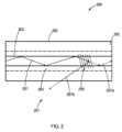
FBGによって提供されるフィードバックは、レーザー発振が図1に示されている様にn次ファイバーラマンレーザーを作り出すことができるようにする。図1は、ラマンレーザー101のレーザー共振器100の或る実施形態の断面概略図である。共振器100は、コア103と、クラッディング104と、外側クラッディング105と、を有する光ファイバー102を有している。共振器100は、この実施形態ではFBG106である反射部材、を有している。共振器100は、図に示されていないが光ファイバー102の長さに沿って左の方向に、FBGから距離を置いて配置されている第2の反射部材を有している。レーザーの伝播は、点線107aによって示されており、順方向光と反射光の経路は矢印107と107bによってそれぞれ示されている。 The feedback provided by the FBG enables lasing to produce an nth order fiber Raman laser as shown in FIG. FIG. 1 is a cross-sectional schematic diagram of an embodiment of a
加えて、レーザー共振器の或る実施形態では、「n+1」次ラマンモードの成長は、図2に示されている様に、「n+1」次ラマンモードでのエネルギーがファイバーコアから射出されるようにFBGを傾けることによって抑制できる。この抑制は、n次ラマンモードがエネルギー的に従来のパワー限界を超えて増大することを可能にさせる。この実施形態では、レーザーパターンはクラッディングの中まで延びていることに注目されたい。 Additionally, in certain embodiments of the laser cavity, the growth of the 'n+1' order Raman mode is such that the energy in the 'n+1' order Raman mode is ejected from the fiber core, as shown in FIG. can be suppressed by tilting the FBG to This suppression allows the n-th order Raman mode to grow energetically beyond the conventional power limit. Note that in this embodiment the laser pattern extends into the cladding.
図2を見ると、ラマンレーザー201のレーザー共振器200の或る実施形態の断面概略図が提供されている。共振器200は、コア203と、クラッディング204と、外側クラッディング205と、を有する光ファイバー202を有している。共振器200は、この実施形態では角度の付けられたFBG206である反射部材、を有している。共振器200は、図に示されていないが光ファイバー202の長さに沿って左の方向に、FBG206から距離を置いて配置されている第2の反射部材を有している。レーザーの伝播は、点線207aによって示されており、順方向光と反射光の経路は矢印207と207bによってそれぞれ示されている。FBGが刻まれるやり方、例えばコア及びクラッディング中に位置決めされ、光ファイバーの軸に対して位置決めされることが、コアを出てゆく反射光706bをもたらすことに注目されたい。共振器は、図に示されていないが光ファイバーの長さに沿って左の方向に、FBGから距離を置いて配置されている第2の反射部材を有している。 Turning to FIG. 2, a cross-sectional schematic diagram of an embodiment of
加えて、レーザーパターンは、図には断面で単数又は複数の線として示されているが、典型的には円盤形状であり、即ち、パターンが送達されるコア区域の外側をなぞるように又は意図されるならコア区域を充填するようにロッドラインファイバーの線に沿っているものと理解される。パターンの形状は、必ずしも円盤形状でなくてもよく、半円盤、垂直線、平面、三角形、円錐形、及び他の形状、並びにこれらの組合せ及び変形型が使用されてもよい。更に、ファイバー及びファイバーコアが円でない、例えば方形であるなら、その場合、レーザービーム送達パターンは、ファイバーの形状をなぞることが意図される場合にはそうするように当該ファイバーと同じ形状、例えば方形とすることができる。 Additionally, the laser pattern, although shown in the figures as a line or lines in cross-section, is typically disc-shaped, i. It is understood that along the lines of the rod line fibers to fill the core area, if any. The shape of the pattern need not be disk-shaped, and half-disks, vertical lines, planes, triangles, cones, and other shapes and combinations and variations thereof may be used. Furthermore, if the fiber and fiber core are non-circular, e.g., square, then the laser beam delivery pattern should be the same shape as the fiber, e.g., square, so as to follow the shape of the fiber if it is intended to do so. can be
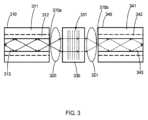
或る実施形態では、図3に示されている様に、光ファイバーの、ファイバーブラッググレーティングが光ファイバー中に直接書き込まれている区分の場所に、更に体積ブラッググレーティング(VBG)が使用されている。かくして、この実施形態は、外側クラッディング311と、内側クラッディング312と、コア313と、を有する第1の光ファイバー区分310を有している。レンズ、即ちレンズ320の組立体が、光路内でファイバー310とVGB331が刻まれた光学部材330との間に配置されている。レンズ321が、VGB331と、外側クラッディング341、内側クラッディング342、及びコア343を有する第2の光ファイバー区分340との間に配置されている。光(矢印によって図示)は、適切なレンズ320でVBG331に入射結合され(矢印370aの順方向及び反射)、適切なレンズ321でVBD331に出射結合される(矢印370b、レーザー伝播)。入射光及び出射光は、ファイバー結合装置を構成している光ファイバーの中へ案内される。ファイバー結合型VBGは、ラマン活性ファイバーの入力及び出力へ継ぎ合わされていて、ファイバーブラッググレーティングを使用するのと同じ成果を実現する。共振器は、図に示されていないが光ファイバー310の長さに沿って左の方向に、VBGから距離を置いて配置されている第2の反射部材を有している。 In one embodiment, as shown in FIG. 3, a volume Bragg grating (VBG) is also used in the section of the optical fiber where the fiber Bragg grating is written directly into the optical fiber. Thus, this embodiment has a first
或る実施形態では、体積ブラッググレーティングが、以上に論じられているやり方でフィードバックを提供するために、図4に示されている様に一片のガラスエンドキャップの中に書き込まれている(例えば、コア、クラッディング、又はそれら両方のレーザー変質区域を作り出すことによって形成されている)。かくして、この実施形態は、外側クラッディング411と、内側クラッディング412と、コア413と、を有する光ファイバー区分410を有している。光ファイバーの面414は、光学部材430、例えばガラスエンドキャップ、に機械的及び光学的に接触しており、例えば光学部材430へ融合されている。VGB431が部材430中に刻まれている。光(矢印によって図示)は、VBG431に入射及び出射結合され(矢印470)、そこから伝播される(矢印470a)。かくして、図4の構成はファイバーレーザー共振器の一端又は両端を形成することができる。 In one embodiment, a volume Bragg grating is written into a piece of glass endcap as shown in FIG. 4 to provide feedback in the manner discussed above (e.g., (formed by creating a laser-altered zone in the core, the cladding, or both). Thus, this embodiment has an
FBG又はVBGは、図5の実施形態に示されている様に、低次モードを反射するために光伝播方向の法線に対して湾曲した面で以て書き込まれていてもよい。図5を見ると、レーザーのレーザー共振器のための反射部材500の或る実施形態の断面概略図が提供されている。反射部材500は、コア503と、内側クラッディング504と、外側クラッディング505と、を有する光ファイバー502を有している。反射部材500は、湾曲した形状に刻まれた又は書き込まれたVGB531を有する光学部材530、例えばガラスエンドキャップ、を有している。レーザーの伝播は点線507aによって示されており、反射光でコア内に留まっている順方向光と反射光の経路は矢印507によって示され、コアから外へ方向決めされ例えばコアには二度と進入しない反射光の経路は矢印507bによって示されている。 FBGs or VBGs may be written with surfaces curved to the normal to the direction of light propagation to reflect lower order modes, as shown in the embodiment of FIG. Turning to FIG. 5, a cross-sectional schematic diagram of an embodiment of a
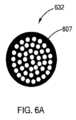
図6及び図6Aに示されている実施形態は、「モスアイ」レーザービーム送達パターンの様な互い違い又は分散パターンであり、光ファイバー端部へ直接に送達されて、モスアイパターンレーザー変質領域を作り出すことができ、また以上に論じられているやり方でのフィードバック例えば反射を提供すること、更には実施形態ではレーザービームの伝播を提供することができる。かくして、図6を見ると、レーザーのレーザー共振器のための反射部材600の或る実施形態の断面概略図が示されている。反射部材600は、コア603と、内側クラッディング604と、外側クラッディング605と、を有する光ファイバー602を有している。レーザー作用帯630は、ファイバー602の端部に設置されている。また、この実施形態では、ファイバー面607に。実施形態では、ファイバー602内部の他の点に配置されることもあり得るものと理解しておきたい。図6Aを見ると、モスアイパターン631を示すファイバー面607の平面概略図が示されている。 The embodiments shown in FIGS. 6 and 6A are staggered or divergent patterns, such as the "moth-eye" laser beam delivery pattern, which can be delivered directly to the end of an optical fiber to create a moth-eye pattern laser-altered region. It can also provide feedback, such as reflection, in the manner discussed above and, in embodiments, laser beam propagation. Thus, turning to FIG. 6, there is shown a cross-sectional schematic diagram of an embodiment of a
図1から図6には、光ファイバーの一区分のみが示されており、これらの図面は略図でしかなく、ファイバーの実際の長さはより長く、実施形態ではなおいっそう長く、例えば何桁も長く、図に描かれているよりも数桁長いものと理解しておきたい。 Only one section of the optical fiber is shown in FIGS. 1 to 6, these drawings are only schematic and the actual length of the fiber is longer, even longer in embodiments, e.g. orders of magnitude longer. , to be several orders of magnitude longer than depicted in the figure.
全ファイバーフィードバック機構は、全ファイバーn次ラマンファイバーレーザー、望ましくは全ファイバーn次モノリシックラマンファイバーレーザーが構築されることを可能にする。 An all-fiber feedback mechanism allows an all-fiber nth-order Raman fiber laser, preferably an all-fiber nth-order monolithic Raman fiber laser, to be constructed.
図7Aから図7F。これらの図には、ラマン定在波及び出力光パワーの或る実施形態について示されるレーザー共振器のモデル化された内部パワー及び他の因子を描く一連のグラフが示されている。 Figures 7A to 7F. These figures show a series of graphs depicting the modeled internal power of a laser cavity and other factors shown for certain embodiments of Raman standing waves and output optical power.
図7Aには、メートル単位のファイバー長さに対するワット(W)単位の信号パワーがグラフ化されており、1次ラマンについては追加損失有り(2次ラマン損失0dB)とされている。1次ラマン出力パワーは56Wである。曲線701は457nm順方向信号であり、曲線702は457nm逆方向信号である。 FIG. 7A plots signal power in Watts (W) against fiber length in meters, with additional loss for the 1st order Raman (0 dB 2nd order Raman loss). The primary Raman output power is 56W.
図7Bには、2次ラマン(2次ラマン損失0dB)について、メートル単位のファイバー長さに対するワット(W)単位の信号パワーがグラフ化されている。2次ラマン出力パワーは55Wである。曲線711は466nm順方向信号であり、曲線712は466nm逆方向信号である。 FIG. 7B plots signal power in Watts (W) versus fiber length in meters for 2nd order Raman (0 dB 2nd order Raman loss). The secondary Raman output power is 55W.
図7Cには、1次ラマン(2次ラマン損失6dB)について、メートル単位のファイバー長さに対するワット(W)単位の信号パワーがグラフ化されている。1次ラマン出力パワーは120Wである。曲線721は457nm順方向信号であり、曲線722は457nm逆方向信号である。 FIG. 7C plots the signal power in Watts (W) against fiber length in meters for 1st order Raman (6 dB 2nd order Raman loss). The primary Raman output power is 120W.
図7Dには、2次ラマン(2次ラマン損失6dB)について、メートル単位のファイバー長さに対するワット(W)単位の信号パワーがグラフ化されている。2次ラマン出力パワーは15Wである。曲線731は466nm順方向信号であり、曲線732は466nm逆方向信号である。 FIG. 7D plots signal power in Watts (W) against fiber length in meters for 2nd order Raman (6 dB 2nd order Raman loss). The secondary Raman output power is 15W.
図7Eには、1次ラマン(2次ラマン損失13dB)について、メートル単位のファイバー長さに対するワット(W)単位の信号パワーがグラフ化されている。1次ラマン出力パワーは193Wである。曲線741は457nm順方向信号であり、曲線742は457nm逆方向信号である。 FIG. 7E plots signal power in Watts (W) against fiber length in meters for first-order Raman (second-
図7Fには、2次ラマン(2次ラマン損失13dB)について、メートル単位のファイバー長さに対するワット(W)単位の信号パワーがグラフ化されている。2次ラマン出力パワーは0Wである。曲線751は466nm順方向信号であり、曲線752は466nm逆方向信号である。 FIG. 7F plots signal power in Watts (W) against fiber length in meters for 2nd order Raman (13 dB 2nd order Raman loss). The secondary Raman output power is 0W.
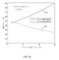
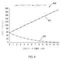
図9を見ると、レーザーキャビティ中の2次ラマンストークスでの追加損失(単位dB)の関数としての1次ラマンストークス線901及び2次ラマンストークス線902それぞれのワット単位の出力パワーのグラフ900が提供されている。かくして、このグラフは、2次ラマンストークス線におけるレーザー共振器内の損失を増加させることによる、2次ラマンレーザー処理の抑制を示している。ファイバーラマンレーザー内の定在波パワーが示されている。 Looking at FIG. 9, a
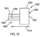
図10を見ると、約400nmから約700nmの波長領域のレーザービームを生成するためのレーザー共振器1000の或る実施形態の断面図が示されている。レーザー共振器は、コア1002及びエンドキャップ1003とクラッディング1004とを備え一体型フィードバック機構1005を有する光ファイバー1001を有しており、フィードバック機構1005は、ファイバー中に配置されている第1反射部材1006及びエンドキャップ1003の表面1008に配置されている第2反射部材1007を有し、第1反射部材は、光ファイバーの或る長さに沿って配置されていて、部材間に或る距離1010を画定している。第2反射部材1007は、或るラマン次数へのフィードバック望ましくは第1のラマン次数へのフィードバックを提供し且つn=2のラマン次数へのフィードバックを提供しない誘電体被覆である。 Turning to FIG. 10, there is shown a cross-sectional view of an embodiment of a
図11を見ると、約400nmから約700nmの波長領域のレーザービームを生成するためのレーザー共振器の或る実施形態の断面図が示されている。レーザー共振器は、第1のラマン次数の、ポンプ波長にARである誘電体被覆を有するエンドキャップ1104と、第1のラマン次数の、ポンプ波長にR<95%HRである誘電体被覆1102を有する第2エンドキャップ1105と、それらエンドキャップへ接続しエンドキャップを光通信に置くファイバー1103と、を有している。 Turning to FIG. 11, there is shown a cross-sectional view of an embodiment of a laser cavity for producing laser beams in the wavelength region of approximately 400 nm to approximately 700 nm. The laser cavity has an
或る実施形態では、第2反射部材は、第1のラマン次数へのフィードバックを提供することができるブラッググレーティングであり、第1のラマン次数へのフィードバックを提供する。 In some embodiments, the second reflective member is a Bragg grating capable of providing feedback to the first Raman order and provides feedback to the first Raman order.
別の実施形態では、2つのエンドキャップがファイバーのどちらかの端部に利用されている。この実施形態では、図10の実施形態の様に、エンドキャップの面は、反射部材を形成する誘電体被覆を有している。第2エンドキャップの面も第2反射部材を形成する誘電体被覆を有している。エンドキャップの面上の誘電体被覆は、第2のラマン次数への又はn>1からxxまでの何れかの他のラマン次数へのフィードバックを提供しない狭帯域誘電体被覆とすることができる。それは、第1のラマン次数へのフィードバックを提供し且つポンプ波長における低反射被覆である狭帯域誘電体被覆とすることができる。両方の反射部材を誘電体被覆とし第1のラマン次数へのフィードバックを提供させるようにすることもでき、その場合、どちらもがポンプ波長における低反射被覆であるのが望ましい。両方の反射被覆を誘電体被覆とし、第1の誘電体被覆はポンプ波長について低反射性を有するものとし、第2の誘電体被覆はポンプ波長について高反射性を有するものとし、レーザーの変換効率を改善するために共振器を通るポンプ波長のための第2のパスを提供させるようにすることもできる。 In another embodiment, two end caps are utilized on either end of the fiber. In this embodiment, like the embodiment of FIG. 10, the face of the end cap has a dielectric coating forming a reflective member. The face of the second endcap also has a dielectric coating that forms a second reflective member. The dielectric coating on the face of the endcap can be a narrowband dielectric coating that provides no feedback to the second Raman order or any other Raman order from n>1 to xx. It can be a narrowband dielectric coating that provides feedback to the first Raman order and is a low reflection coating at the pump wavelength. Both reflective members may be dielectric coatings to provide feedback to the first Raman order, in which case both are preferably low reflection coatings at the pump wavelength. Both reflective coatings are dielectric coatings, the first dielectric coating has low reflectivity for the pump wavelength, the second dielectric coating has high reflectivity for the pump wavelength, and the conversion efficiency of the laser is It is also possible to provide a second pass for the pump wavelength through the resonator to improve .
本発明の或る実施形態では、ファイバーレーザーの第1のラマン次数へのフィードバックを提供するが第2のラマン次数へのフィードバックを提供しないブラッググレーティングを使用するファイバーレーザーが提供されている。 In some embodiments of the present invention, a fiber laser is provided that uses a Bragg grating that provides feedback to the first Raman order of the fiber laser but not to the second Raman order.
本発明の或る実施形態では、ファイバーレーザーの第1のラマン次数へのフィードバックを提供するが第2のラマン次数へのフィードバックは提供しないブラッググレーティングであって、400-700nmの波長領域で動作するためにフェムト秒パルスを使用して光ファイバー中に作られているブラッググレーティング、を使用するファイバーレーザーが提供されている。 In one embodiment of the invention, a Bragg grating that provides feedback to the first Raman order of a fiber laser but not to the second Raman order and operates in the 400-700 nm wavelength region. A fiber laser has been provided that uses a Bragg grating, which is fabricated in an optical fiber using femtosecond pulses for the purpose.
本発明の或る実施形態では、ファイバーレーザーの第1のラマン次数へのフィードバックを提供するが第2のラマン次数へのフィードバックは提供しないブラッググレーティングであって、純粋溶融石英コアファイバー中に作られているブラッググレーティング、を使用するファイバーレーザーが提供されている。 In one embodiment of the invention, a Bragg grating that provides feedback to the first Raman order of a fiber laser but not to the second Raman order and is fabricated in a pure fused silica core fiber. Fiber lasers have been provided that use Bragg gratings.
本発明の或る実施形態では、ファイバーレーザーの第1のラマン次数へのフィードバックを提供するが第2のラマン次数へのフィードバックは提供しないブラッググレーティングであって、リンドープされたコアファイバー中に作られているブラッググレーティング、を使用するファイバーレーザーが提供されている。 In one embodiment of the invention, a Bragg grating that provides feedback to the first Raman order of a fiber laser but not to the second Raman order is fabricated in a phosphorus-doped core fiber. Fiber lasers have been provided that use Bragg gratings.
本発明の或る実施形態では、ファイバーレーザーの第1のラマン次数へのフィードバックを提供するが第2のラマン次数へのフィードバックは提供しないブラッググレーティングであって、ドープされたコア中に作られているブラッググレーティング、を使用するファイバーレーザーが提供されている。 In one embodiment of the invention, a Bragg grating that provides feedback to the first Raman order of a fiber laser but not to the second Raman order and is fabricated in a doped core A fiber laser using a Bragg grating is provided.
本発明の或る実施形態では、ファイバーレーザーの第1のラマン次数へのフィードバックを提供するが第2のラマン次数へのフィードバックは提供しないブラッググレーティングを使用するファイバーレーザーが提供されており、コアは、500nmより下の波長で使用される場合は感光性ドーパント例えばゲルマニウムでドープされていない。 In one embodiment of the present invention, a fiber laser is provided using a Bragg grating that provides feedback to the first Raman order of the fiber laser but not to the second Raman order, the core comprising: , is not doped with a photosensitive dopant such as germanium when used at wavelengths below 500 nm.
本発明の或る実施形態では、ファイバーレーザーの第1のラマン次数へのフィードバックを提供するが第2のラマン次数へのフィードバックは提供しないブラッググレーティングを使用するファイバーレーザーが提供されており、グレーティングは、光ファイバーのコア内にフィードバックを提供するために、光ファイバー中の光波方向に対して垂直入射に刻まれている。 In one embodiment of the present invention, a fiber laser is provided using a Bragg grating that provides feedback to the first Raman order of the fiber laser but not to the second Raman order, the grating being , is scribed at normal incidence to the light wave direction in the optical fiber to provide feedback within the core of the optical fiber.
本発明の或る実施形態では、ラマン利得スペクトル内の特定の波長のフィードバックを提供するファイバーブラッググレーティングが提供されている。 In some embodiments of the present invention, fiber Bragg gratings are provided that provide feedback of specific wavelengths within the Raman gain spectrum.
本発明の或る実施形態では、第1のラマン次数のラマン利得スペクトル全体に亘るフィードバックを提供するファイバーブラッググレーティングが提供されている。 In some embodiments of the present invention, a fiber Bragg grating is provided that provides feedback across the first Raman order Raman gain spectrum.
本発明の或る実施形態では、第2のラマン次数への損失を提供するファイバーブラッググレーティングが提供されている。 In some embodiments of the present invention, fiber Bragg gratings are provided that provide loss to the second Raman order.
本発明の或る実施形態では、伝播モードをファイバーのコアから外へ向け直すために、光ファイバー中の光波方向の法線に対して角度を付けて刻まれているファイバーブラッググレーティングが提供されている。 An embodiment of the present invention provides a fiber Bragg grating that is scribed at an angle to the normal of the light wave direction in the optical fiber to redirect propagating modes out of the core of the fiber. .
本発明の或る実施形態では、nのモードのみを折り返しファイバーのコアの中へ向け直すために、光ファイバー中の光波方向の法線に対して湾曲した形状、例えば凸状、に刻まれているファイバーブラッググレーティングが提供されており、ここにnは1から<4まで変わり得る。 In some embodiments of the present invention, it is sculpted into a curved shape, e.g. convex, with respect to the normal to the light wave direction in the optical fiber to redirect only the n modes into the core of the folded fiber. Fiber Bragg gratings are provided, where n can vary from 1 to <4.
本発明の或る実施形態では純粋溶融石英コアファイバー中に作られているファイバーブラッググレーティングが提供されている。 One embodiment of the present invention provides a fiber Bragg grating fabricated in a pure fused silica core fiber.
本発明の或る実施形態では、ファイバーのリンドープされたコア中に作られているファイバーブラッググレーティングが提供されている。 An embodiment of the present invention provides a fiber Bragg grating fabricated in a phosphorous-doped core of a fiber.
本発明の或る実施形態では、ドープされたコア中に作られているファイバーブラッググレーティングが提供されている。 An embodiment of the present invention provides a fiber Bragg grating fabricated in a doped core.
本発明の或る実施形態では、ファイバーブラッググレーティングが提供されており、ここにコアは500nmより下の波長で使用される場合は感光性ドーパントでドープされていない。 In one embodiment of the invention, a fiber Bragg grating is provided wherein the core is undoped with a photosensitive dopant for use at wavelengths below 500 nm.
本発明の或る実施形態では、nのラマン次数に亘る損失を提供するファイバーブラッググレーティングが提供されており、ここにnは2から>10まで変わり得る。 In some embodiments of the present invention, fiber Bragg gratings are provided that provide loss over n Raman orders, where n can vary from 2 to >10.
本発明の或る実施形態では、400-700nmの波長領域で動作するためにフェムト秒パルスを使用して作られているファイバー結合型体積ブラッググレーティングが提供されている。 An embodiment of the present invention provides a fiber-coupled volume Bragg grating fabricated using femtosecond pulses for operation in the 400-700 nm wavelength region.
本発明の或る実施形態では、ガラス中に作られているファイバー結合型体積ブラッググレーティングが提供されている。 In some embodiments of the present invention, fiber-coupled volume Bragg gratings fabricated in glass are provided.
本発明の或る実施形態では、光ファイバーのコア内にフィードバックを提供するために、ガラス中に光波方向に対する垂直入射で刻まれているファイバー結合型体積ブラッググレーティングが提供されている。 In one embodiment of the present invention, a fiber-coupled volume Bragg grating is provided that is inscribed in glass at normal incidence to the light wave direction to provide feedback within the core of the optical fiber.
本発明の或る実施形態では、ラマン利得スペクトル内の特定の波長のフィードバックを提供するファイバー結合型体積ブラッググレーティングが提供されている。 In some embodiments of the present invention, fiber-coupled volume Bragg gratings are provided that provide feedback of specific wavelengths within the Raman gain spectrum.
本発明の或る実施形態では、ラマン利得スペクトル全体に亘るフィードバックを提供するファイバー結合型体積ブラッググレーティングが提供されている。 In some embodiments of the present invention, fiber-coupled volume Bragg gratings are provided that provide feedback across the Raman gain spectrum.
本発明の或る実施形態では、第2のラマン次数への損失を提供するファイバー結合型体積ブラッググレーティングが提供されている。 An embodiment of the present invention provides a fiber-coupled volume Bragg grating that provides loss to the second Raman order.
本発明の或る実施形態では、伝播モードをファイバーのコアから外へ向け直すために、光ファイバー中に光波方向の法線に対して角度を付けて刻まれているファイバー結合型体積ブラッググレーティングが提供されている。 An embodiment of the present invention provides a fiber-coupled volume Bragg grating sculpted into the optical fiber at an angle to the normal to the light wave direction to redirect propagating modes out of the core of the fiber. It is
本発明の或る実施形態では、nのモードのみを折り返しファイバーのコアの中へ向け直すために、光ファイバー中に光波方向の法線に対して湾曲した形状に刻まれているファイバー結合型体積ブラッググレーティングが提供されており、ここに、nは1から<4まで変わり得る。 In some embodiments of the present invention, a fiber-coupled volume Bragg carved into the optical fiber in a shape curved with respect to the normal to the wave direction to redirect only the n modes into the core of the folded fiber. Gratings are provided where n can vary from 1 to <4.
本発明の或る実施形態では、ガラス中に作られているファイバー結合型体積ブラッググレーティングが提供されている。 In some embodiments of the present invention, fiber-coupled volume Bragg gratings fabricated in glass are provided.
本発明の或る実施形態では、ファイバー結合型体積ブラッググレーティングが提供されており、ここにガラスは500nmより下の波長で使用される場合は感光性ドーパントでドープされていない。 In some embodiments of the present invention, fiber-coupled volume Bragg gratings are provided wherein the glass is not doped with photosensitive dopants for use at wavelengths below 500 nm.
本発明の或る実施形態では、nのラマン次数に亘る損失を提供するファイバー結合型体積ブラッググレーティングが提供されており、ここにnは1から>10まで変わり得る。 In some embodiments of the present invention, fiber-coupled volume Bragg gratings are provided that provide loss over n Raman orders, where n can vary from 1 to >10.
本発明の或る実施形態では、400-700nmの波長領域で動作するためにフェムト秒パルスを使用して作られている体積ブラッググレーティングが提供されている。 An embodiment of the present invention provides a volume Bragg grating fabricated using femtosecond pulses for operation in the 400-700 nm wavelength region.
本発明の或る実施形態では、ガラス中に作られているファイバー光学器エンドキャップの中に書き込まれている体積ブラッググレーティングが提供されている。 An embodiment of the present invention provides a volume Bragg grating written into a fiber optic endcap that is fabricated in glass.
本発明の或る実施形態では、ファイバー光学器エンドキャップの中に書き込まれている体積ブラッググレーティングであって、光ファイバーのコア内にフィードバックを提供するために、ガラス中に光波方向に対する垂直入射で刻まれていて光ファイバーのNAに整合するように湾曲している体積ブラッググレーティングが提供されている。 In one embodiment of the invention, a volume Bragg grating written into a fiber optic end cap is engraved into the glass at normal incidence to the light wave direction to provide feedback within the core of the optical fiber. A volume Bragg grating is provided which is rare and curved to match the NA of the optical fiber.
本発明の或る実施形態では、ファイバー光学器エンドキャップの中に書き込まれている体積ブラッググレーティングであって、ラマン利得スペクトル内の特定の波長のフィードバックを提供する体積ブラッググレーティングが提供されている。 An embodiment of the present invention provides a volume Bragg grating written into a fiber optic endcap that provides feedback of specific wavelengths within the Raman gain spectrum.
本発明の或る実施形態では、ファイバー光学器エンドキャップの中に書き込まれている体積ブラッググレーティングであって、ラマン利得スペクトル全体に亘るフィードバックを提供する体積ブラッググレーティングが提供されている。 An embodiment of the present invention provides a volume Bragg grating written into a fiber optic endcap that provides feedback over the Raman gain spectrum.
本発明の或る実施形態では、第2のラマン次数への損失を提供するために、ファイバー光学器エンドキャップの中に書き込まれている体積ブラッググレーティングが提供されている。 Some embodiments of the present invention provide a volume Bragg grating written into the fiber optic endcap to provide loss to the second Raman order.
本発明の或る実施形態では、ファイバー光学器エンドキャップの中に書き込まれている体積ブラッググレーティングであって、伝播モードをファイバーのコアから外へ向け直すために光ファイバー中に光波方向の法線に対して角度を付けて刻まれている体積ブラッググレーティングが提供されている。 In one embodiment of the present invention, a volume Bragg grating written into a fiber optic end cap is oriented normal to the light wave direction into the optical fiber to redirect propagating modes out of the core of the fiber. A volume Bragg grating is provided which is sculpted at an angle to it.
本発明の実施形態では、ファイバーブラッググレーティング、体積ブラッググレーティング、空間グレーティング(例えばモスアイグレーティング)、及びブラッググレーティングを有するエンドキャップであって、次の特徴、即ち、ガラス内に作られていて;ここにガラスは500nmより下の波長で使用される場合には感光性ドーパントでドープされていない;nのラマン次数に亘る損失を提供し、ここにnは2から>10まで変わり得る;400-700nmの波長領域で動作するためにフェムト秒パルスを使用して作られている;光ファイバーのコア内にフィードバックを提供するためにガラス中に光波方向に対する垂直入射で作られている;ラマン利得スペクトル内の特定の波長のフィードバックを提供する;ラマン利得スペクトル全体に亘るフィードバックを提供する;第2のラマン次数への損失を提供する;及び、伝播モードをファイバーのコアから外へ向け直すために光ファイバー中に光波方向の法線に対して角度を付けて刻まれている、という特徴のうちの1つ又はそれ以上を有しているファイバーブラッググレーティング、体積ブラッググレーティング、空間グレーティング、及びブラッググレーティングを有するエンドキャップが提供されている。 Embodiments of the present invention are endcaps having fiber Bragg gratings, volume Bragg gratings, spatial gratings (e.g., moth-eye gratings), and Bragg gratings having the following features: made in glass; The glass is not doped with photosensitive dopants when used at wavelengths below 500 nm; it provides loss over n Raman orders, where n can vary from 2 to >10; made using femtosecond pulses to operate in the wavelength domain; made at normal incidence to the light wave direction in glass to provide feedback in the core of an optical fiber; specific within the Raman gain spectrum provide feedback over the entire Raman gain spectrum; provide loss to the second Raman order; an end cap having a fiber Bragg grating, a volume Bragg grating, a spatial grating, and a Bragg grating having one or more of the characteristics of being sculpted at an angle to a directional normal; provided.
FBGを作るためのフェムト秒レーザーの使用は、モノリシックファイバーレーザー共振器を形成するためにファイバー中に波長特異的屈折率変化を生じさせる好適な方法であるが、他の方法が採用され得る又は後日開発され得るものと認識される。例えば、FBGは、エキシマレーザーによって提供される深部UV放射、又は光ファイバーのX線への暴露、又はスペクトルの可視部分で動作するためにFBGを作るべく光ファイバーの屈折率を改変する他の方法、によって誘導されてもよい。 The use of femtosecond lasers to make FBGs is the preferred method of producing wavelength-specific refractive index changes in the fiber to form monolithic fiber laser cavities, although other methods could be adopted or at a later date. It is recognized that it can be developed. For example, FBGs can be formed by deep UV radiation provided by excimer lasers, or by exposing optical fibers to X-rays, or other methods of modifying the refractive index of optical fibers to make them to operate in the visible portion of the spectrum. may be induced.
光ファイバー中にレーザー変質領域を作り出すために、及びVBG、FBG、及び光ファイバー材料の屈折率の変化した他の区域を形成するために、使用することのできるフェムト秒レーザーは、商業的に入手可能なものが幾つかある。レーザー変質領域を作り出すには、約10ピコ秒未満、約5ピコ秒未満、約1ピコ秒未満、約500フェムト秒未満、及び約100フェムト秒未満のパルス幅を有するレーザービームが使用され得るものと考えられる。 Femtosecond lasers that can be used to create laser-altered regions in optical fibers and to create VBGs, FBGs, and other regions of altered refractive index in optical fiber materials are commercially available. There are some things. A laser beam having a pulse width of less than about 10 picoseconds, less than about 5 picoseconds, less than about 1 picosecond, less than about 500 femtoseconds, and less than about 100 femtoseconds can be used to create the laser-altered region. it is conceivable that.
次の実施例は、本発明のLAMシステム、LAM方法、及びラマン発振器レーザーの様々な実施形態を例示するために提供されている。これらの実施例は、例示目的であり、本発明の範囲を限定するものと見なされてはならず、またそれ以外のやり方で本発明の範囲を限定するものでもない。 The following examples are provided to illustrate various embodiments of the LAM systems, LAM methods, and Raman oscillator lasers of the present invention. These examples are for illustrative purposes and should not be construed as limiting the scope of the invention, nor are they intended to otherwise limit the scope of the invention.
実施例1 Example 1
レーザーキャビネットが、パワー調整源と、ポンプレーザーと、10のモノリシックファイバーレーザーと、ビームコンバイナ及び関連の制御システムと、安全インターロック及びモニターと、冷却システム(例えば、ファン、ヒートシンク、又は深冷器の様な別体の冷却システム)と、を有している。パワー調整源は、445nmの波長及び400ワットのパワーを有する半導体レーザーポンプ源にパワー供給し、レーザーポンプ源は、FBGをレーザー共振器の末端として有している10のモノリシックファイバーレーザー共振器へポンプレーザービームを提供する。各モノリシックファイバーレーザー共振器は、453nmの波長と200ワットのパワーを有する初期レーザービームを作り出す。各初期レーザービームはガラスビームコンバイナによって組み合わされて、高度多重モードビーム品質に至るまでの限定された回折で2000ワットを有する出力レーザービームを作り出す。 A laser cabinet contains power conditioning sources, pump lasers, ten monolithic fiber lasers, beam combiners and associated control systems, safety interlocks and monitors, and cooling systems (e.g., fans, heat sinks, or chillers). a separate cooling system). A power adjustment source powers a semiconductor laser pump source with a wavelength of 445 nm and a power of 400 watts, which pumps into ten monolithic fiber laser cavities with FBGs as the ends of the laser cavity. Provides a laser beam. Each monolithic fiber laser cavity produces an initial laser beam with a wavelength of 453 nm and a power of 200 watts. Each initial laser beam is combined by a glass beam combiner to produce an output laser beam with 2000 Watts with limited diffraction to advanced multimode beam quality.
本発明の実施形態の主題である又は本発明の実施形態と関連付けられる新規で画期的なプロセス、材料、性能、又は他の有益な特徴及び特性の根底にある理論を提供する又は当該理論に取り組むうえで必要条件はないことを指摘しておく。それでもなお、本明細書にはこの領域の技術を更に進展させるための様々な理論が提供されている。本明細書に提言されている理論は、別途明示的に表明されていない限り、断じて、保護を与えられるべき特許請求の範囲に記載の発明の範囲を限定、制限、又は狭小化するものではない。本発明を利用するうえでこれらの理論は必要とならないかもしれないし又は実践されないかもしれない。更に理解しておきたいこととして、本発明は、本発明の方法、物品、材料、装置、及びシステムの実施形態の機能、特徴を解説するための新しい理論及びこれまで知られていない理論へとつながる可能性があり、その様な後発理論は保護を与えられるべき本発明の範囲を限定するものではない。 To provide or support the theory underlying any new and innovative processes, materials, performance, or other beneficial features and properties that are the subject of embodiments of the invention or that are associated with embodiments of the invention; Note that there are no prerequisites for working. Nonetheless, various theories are provided herein for further advancement of technology in this area. The theories put forth herein are in no way intended to limit, limit, or narrow the scope of the claimed inventions to which protection is entitled, unless expressly stated otherwise. . These theories may not be required or practiced to utilize the present invention. It should also be understood that the present invention contemplates new and hitherto unknown theories to explain the function and characteristics of embodiments of the methods, articles, materials, devices and systems of the present invention. Such late-comer theories are not intended to limit the scope of the inventions to which protection is entitled.
本明細書に示されているシステム、機器、技法、方法、活動、及び動作の様々な実施形態は、様々な他の活動のために使用されてもよいし、ここに示されている分野に加え他の分野で使用されてもよい。加えて、これらの実施形態は、例えば、将来開発され得る他の機器又は活動と共に;及び、本明細書の教示に基づき一部が改変され得る既存の機器又は活動と共に、使用されてもよい。更に、本明細書に示されている様々な実施形態は互いと一体に異なる様々な組合せで使用されてもよい。而して、例えば、本明細書の様々な実施形態に提供されている構成は互いと共に使用されてもよく、保護を与えられるべき本発明の範囲は、特定の実施形態、特定の実施例、又は特定の図にある実施形態に示されている特定の具現化、構成、又は配列に限定されてはならない。 Various embodiments of the systems, devices, techniques, methods, activities, and operations described herein may be used for various other activities and/or applications in the fields illustrated herein. In addition, it may be used in other fields. In addition, these embodiments may be used, for example, with other equipment or activities that may be developed in the future; and with existing equipment or activities that may be modified in part based on the teachings herein. Moreover, the various embodiments presented herein may be used in various different combinations integrally with each other. Thus, for example, the configurations provided in the various embodiments herein may be used in conjunction with each other and the scope of the invention to which protection is to be accorded may vary depending on the specific embodiment, specific example, or to the specific implementations, configurations, or arrangements shown in the embodiments in certain figures.
発明は、その精神又は本質的な特性から逸脱することなく、ここに具体的に開示されている以外の他の形態に具現化されてもよい。説明されている実施形態は、あらゆる点で、例示にすぎず制限を課すものではないと考えられるべきである。 The invention may be embodied in other forms than those specifically disclosed herein without departing from the spirit or essential characteristics thereof. The described embodiments are to be considered in all respects only as illustrative and not restrictive.
100 レーザー共振器
101 ラマンレーザー
102 光ファイバー
103 コア
104 クラッディング
105 外側クラッディング
106 ファイバーブラッググレーティング、FBG
107 順方向光
107a レーザーの伝播
107b 反射光
200 レーザー共振器
201 ラマンレーザー
202 光ファイバー
203 コア
204 クラッディング
205 外側クラッディング
206 ファイバーブラッググレーティング、FBG
207 順方向光
207a レーザーの伝播
207b 反射光
310 第1の光ファイバー区分
311 外側クラッディング
312 内側クラッディング
313 コア
320、321 レンズ
330 光学部材
331 体積ブラッググレーティング、VBG
340 第2の光ファイバー区分
341 外側クラッディング
342 内側クラッディング
343 コア
370a 順方向光及び反射光
370b レーザー伝播
410 光ファイバー区分
411 外側クラッディング
412 内側クラッディング
413 コア
414 光ファイバーの面
430 光学部材
431 体積ブラッググレーティング、VBG
470 光の入射及び出射結合
470a 光の伝播
500 反射部材
502 光ファイバー
503 コア
504 内側クラッディング
505 外側クラッディング
507 順方向及びコア内に留まる反射光
507a レーザーの伝播
507b コアから外へ方向決めされる反射光
530 光学部材
531 体積ブラッググレーティング、VBG
600 反射部材
602 光ファイバー
603 コア
604 内側クラッディング
605 外側クラッディング
607 ファイバー面
630 レーザー作用帯
631 モスアイパターン
701 457nmの順方向信号を表す曲線
702 457nmの逆方向信号を表す曲線
711 466nmの順方向信号を表す曲線
712 466nmの逆方向信号を表す曲線
721 457nmの順方向信号を表す曲線
722 457nmの逆方向信号を表す曲線
731 466nmの順方向信号を表す曲線
732 466nmの逆方向信号を表す曲線
741 457nmの順方向信号を表す曲線
742 457nmの逆方向信号を表す曲線
751 466nmの順方向信号を表す曲線、
752 466nmの逆方向信号を表す曲線
800 クラッディングのファイバー長手方向に対する角度
801 クラッディング
802 コア
805、805a、805b、805c、805d ショットパターン線
812、813 クラッディング
820 コア
821 クラッディング
822、823 コア
850 レーザーショット
855、856 レーザー変質領域
900 出力パワーのグラフ
901 1次ラマンストークス線
902 2次ラマンストークス線
1000 レーザー共振器
1001 光ファイバー
1002 コア
1003 エンドキャップ
1004 クラッディング
1005 フィードバック機構
1006 第1反射部材
1007 第2反射部材
1008 エンドキャップの面
1010 反射部材間の距離
1102 第1のラマン次数の誘電体被覆
1103 ファイバー
1104、1105 エンドキャップ
100
107
207
340 second
470 Light input and
600
Curve representing reverse signal at 752 466
Claims (17)
Translated fromJapanesea.コアとクラッディングとを有し全ファイバーフィードバック機構を有する光ファイバーを備え、前記フィードバック機構は第1反射部材及び第2反射部材を備え、前記第1反射部材と前記第2反射部材は、前記光ファイバーの長さ方向に沿って配置されていて間に或る距離を画定しており;
b.前記第2反射部材はファイバーブラッググレーティングであり、前記ファイバーブラッググレーティングは1次ラマン光へのフィードバックを提供することができ、前記ファイバーブラッググレーティングは2次ラマン光へのフィードバックを提供することができないようにされた、レーザー共振器。A laser cavity for generating a laser beam in the wavelength range from about 400 nm to about 700 nm,
a. An optical fiber having a core and a cladding and having an all-fiber feedback mechanism, said feedback mechanism comprising a first reflective member and a second reflective member, said first reflective member and said second reflective member being a portion of said optical fiber. arranged along the length and defining a distance therebetween;
b. The second reflecting member is a fiber Bragg grating, wherein the fiber Bragg grating can provide feedback to the primary Raman light and the fiber Bragg grating cannot provide feedback to the secondary Raman light. laser cavity.
a.コアとクラッディングとを有し全ファイバーフィードバック機構を有する光ファイバーを備え、前記フィードバック機構は第1反射部材及び第2反射部材を備え;前記第1反射部材と前記第2反射部材は光ファイバーの長さ方向に沿って配置されていて間に或る距離を画定しており;
b.前記第2反射部材はファイバーブラッググレーティングであり、前記ファイバーブラッググレーティングは或る次数のラマン光の利得スペクトルの全体に亘るフィードバックを提供することができ、他の全ての次数のラマン光へのフィードバックは提供しないようにされた、レーザー共振器。A laser cavity for generating a laser beam in the wavelength range from about 400 nm to about 700 nm,
a. An optical fiber having a core and a cladding and having an all-fiber feedback mechanism, said feedback mechanism comprising a first reflective member and a second reflective member; said first reflective member and said second reflective member being a length of optical fiber. arranged along a direction and defining a distance therebetween;
b. The second reflecting member is a fiber Bragg grating, and the fiber Bragg grating can provide feedback across the gain spectrum of Raman light of one order, and feedback to Raman light of all other orders is A laser cavity that is no longer provided.
a.コアとクラッディングとを有し全ファイバーフィードバック機構を有する光ファイバーを備え、前記フィードバック機構は第1反射部材及び第2反射部材を有し;前記第1反射部材と前記第2反射部材は前記光ファイバーの長さ方向に沿って配置されていて間に或る距離を画定しており;
b.前記第2反射部材はファイバーブラッググレーティングであり、前記ファイバーブラッググレーティングは2次ラマン光への損失を提供することができ、他の全ての次数のラマン光へのフィードバックは提供しないようにされた、レーザー共振器。A laser cavity for generating a laser beam in the wavelength range from about 400 nm to about 700 nm,
a. An optical fiber having a core and a cladding and having an all-fiber feedback mechanism, said feedback mechanism having a first reflective member and a second reflective member; arranged along the length and defining a distance therebetween;
b. wherein said second reflecting member is a fiber Bragg grating, said fiber Bragg grating capable of providing loss to secondary Raman light and not providing feedback to Raman light of all other orders; laser resonator.
a.コア及びエンドキャップとクラッディングとを備え全ファイバーフィードバック機構を有する光ファイバーを備え、前記フィードバック機構は、前記ファイバー中に配置されている第1反射部材及び前記エンドキャップ中に配置されている第2反射部材を備え;前記第1反射部材と前記第2反射部材は前記光ファイバーの長さ方向に沿って配置されていて間に或る距離を画定しており、
b.前記第2反射部材はブラッググレーティングであり、前記ブラッググレーティングは或る次数のラマン光へのフィードバックを提供することができる、光ファイバーを備えている、レーザー共振器。A laser cavity for generating a laser beam in the wavelength range from about 400 nm to about 700 nm,
a. An optical fiber comprising a core and an endcap and a cladding and having an all-fiber feedback mechanism, the feedback mechanism comprising a first reflector member positioned in the fiber and a second reflector positioned in the endcap. a member; said first reflecting member and said second reflecting member are disposed along the length of said optical fiber defining a distance therebetween;
b. A laser cavity comprising an optical fiber, wherein said second reflecting member is a Bragg grating, said Bragg grating capable of providing feedback to Raman light of a certain order.
12. The laser cavity of claim11 , wherein the Bragg grating provides feedback over the entire Raman gain spectrum.
Priority Applications (1)
| Application Number | Priority Date | Filing Date | Title |
|---|---|---|---|
| JP2023099805AJP2023123600A (en) | 2016-04-29 | 2023-06-19 | Monolithic visible wavelength fiber laser |
Applications Claiming Priority (3)
| Application Number | Priority Date | Filing Date | Title |
|---|---|---|---|
| US201662329660P | 2016-04-29 | 2016-04-29 | |
| US62/329,660 | 2016-04-29 | ||
| PCT/US2017/030059WO2017189962A1 (en) | 2016-04-29 | 2017-04-28 | Monolithic visible wavelength fiber laser |
Related Child Applications (1)
| Application Number | Title | Priority Date | Filing Date |
|---|---|---|---|
| JP2023099805ADivisionJP2023123600A (en) | 2016-04-29 | 2023-06-19 | Monolithic visible wavelength fiber laser |
Publications (3)
| Publication Number | Publication Date |
|---|---|
| JP2019517134A JP2019517134A (en) | 2019-06-20 |
| JP2019517134A5 JP2019517134A5 (en) | 2020-02-27 |
| JP7316791B2true JP7316791B2 (en) | 2023-07-28 |
Family
ID=60160141
Family Applications (2)
| Application Number | Title | Priority Date | Filing Date |
|---|---|---|---|
| JP2018556805AActiveJP7316791B2 (en) | 2016-04-29 | 2017-04-28 | Monolithic visible wavelength fiber laser |
| JP2023099805APendingJP2023123600A (en) | 2016-04-29 | 2023-06-19 | Monolithic visible wavelength fiber laser |
Family Applications After (1)
| Application Number | Title | Priority Date | Filing Date |
|---|---|---|---|
| JP2023099805APendingJP2023123600A (en) | 2016-04-29 | 2023-06-19 | Monolithic visible wavelength fiber laser |
Country Status (5)
| Country | Link |
|---|---|
| US (2) | US10656328B2 (en) |
| EP (1) | EP3449537A4 (en) |
| JP (2) | JP7316791B2 (en) |
| CN (1) | CN109792129B (en) |
| WO (1) | WO2017189962A1 (en) |
Families Citing this family (19)
| Publication number | Priority date | Publication date | Assignee | Title |
|---|---|---|---|---|
| US10562132B2 (en) | 2013-04-29 | 2020-02-18 | Nuburu, Inc. | Applications, methods and systems for materials processing with visible raman laser |
| US11612957B2 (en) | 2016-04-29 | 2023-03-28 | Nuburu, Inc. | Methods and systems for welding copper and other metals using blue lasers |
| US10971896B2 (en) | 2013-04-29 | 2021-04-06 | Nuburu, Inc. | Applications, methods and systems for a laser deliver addressable array |
| US11646549B2 (en) | 2014-08-27 | 2023-05-09 | Nuburu, Inc. | Multi kW class blue laser system |
| US10612371B2 (en)* | 2015-04-21 | 2020-04-07 | Halliburton Energy Services, Inc. | Partially reflective materials and coatings for optical communication in a wellbore |
| WO2017189982A1 (en) | 2016-04-29 | 2017-11-02 | Nuburu, Inc. | Visible laser additive manufacturing |
| US12172377B2 (en) | 2016-04-29 | 2024-12-24 | Nuburu, Inc. | Blue laser metal additive manufacturing system |
| JP6911153B2 (en) | 2017-01-31 | 2021-07-28 | ヌブル インク | Methods and systems for welding copper using a blue laser |
| EP4220252A3 (en) | 2017-04-21 | 2023-08-09 | Nuburu, Inc. | Multi-clad optical fiber |
| KR102416499B1 (en) | 2017-06-13 | 2022-07-01 | 누부루 인크. | Ultra-Dense Wavelength Beam Combination Laser System |
| CN117031615A (en) | 2018-05-04 | 2023-11-10 | 努布鲁有限公司 | Three-clad optical fiber |
| JP2019198431A (en)* | 2018-05-15 | 2019-11-21 | 株式会社三洋物産 | Game machine |
| WO2020107030A1 (en)* | 2018-11-23 | 2020-05-28 | Nuburu, Inc | Multi-wavelength visible laser source |
| CA3127651A1 (en) | 2019-02-02 | 2020-08-06 | Nuburu, Inc. | High reliability, high power, high brightness blue laser diode systems and methods of making the same |
| DE102020212817A1 (en)* | 2020-10-09 | 2022-04-14 | Trumpf Laser Gmbh | Optical fiber unit, laser system with such an optical fiber unit and method for evaluating a coupling quality of the coupling of useful light into such an optical fiber unit |
| JP7540549B2 (en)* | 2022-08-17 | 2024-08-27 | 株式会社三洋物産 | Gaming Machines |
| JP7540550B2 (en)* | 2022-08-17 | 2024-08-27 | 株式会社三洋物産 | Gaming Machines |
| JP7540551B2 (en)* | 2022-08-17 | 2024-08-27 | 株式会社三洋物産 | Gaming Machines |
| JP7540548B2 (en)* | 2022-08-17 | 2024-08-27 | 株式会社三洋物産 | Gaming Machines |
Citations (11)
| Publication number | Priority date | Publication date | Assignee | Title |
|---|---|---|---|---|
| JP2001042141A (en) | 1999-08-04 | 2001-02-16 | Mitsubishi Cable Ind Ltd | Method for manufacturing fiber grating |
| JP2001330754A (en) | 2000-05-22 | 2001-11-30 | Nec Corp | Fiber type optical coupler, method of manufacturing the same, and optical parts, transmitter and receiver, and device using this coupler |
| JP2004020926A (en) | 2002-06-17 | 2004-01-22 | Fujikura Ltd | Manufacturing method of optical waveguide component with grating |
| JP2006527494A (en) | 2003-06-12 | 2006-11-30 | エスピーアイ レーザーズ ユーケー リミテッド | Optical device for providing light radiation having a luminance converter |
| US20090225793A1 (en) | 2008-03-10 | 2009-09-10 | Redwood Photonics | Method and apparatus for generating high power visible and near-visible laser light |
| JP2011102919A (en) | 2009-11-11 | 2011-05-26 | Hitachi Ltd | Optical transmitter module and method of manufacturing the same |
| JP2013509313A (en) | 2009-10-30 | 2013-03-14 | ドゥ ラ リュ インターナショナル リミティド | Security device and security device manufacturing method |
| JP2014194538A (en) | 2013-02-21 | 2014-10-09 | Ofs Fitel Llc | Refraction index-matched grating inscription |
| WO2014179345A1 (en) | 2013-04-29 | 2014-11-06 | Zediker Mark S | Devices, systems, and methods for three-dimensional printing |
| WO2016033343A1 (en) | 2014-08-27 | 2016-03-03 | Nuburu, Inc. | Applications, methods and systems for materials processing with visible raman laser |
| JP2018538569A (en) | 2015-11-18 | 2018-12-27 | マッコーリー ユニバーシティー | High power Raman laser system and method |
Family Cites Families (60)
| Publication number | Priority date | Publication date | Assignee | Title |
|---|---|---|---|---|
| IT1119679B (en) | 1979-03-05 | 1986-03-10 | Fiat Auto Spa | EQUIPMENT FOR CARRYING OUT TREATMENTS ON METAL PIECES BY MEANS |
| US4679198A (en) | 1986-04-04 | 1987-07-07 | North American Philips Corporation | Solid-state tunable laser |
| US4879449A (en) | 1987-01-30 | 1989-11-07 | Duley Walter W | Means of enhancing laser processing efficiency of metals |
| US5393482A (en) | 1993-10-20 | 1995-02-28 | United Technologies Corporation | Method for performing multiple beam laser sintering employing focussed and defocussed laser beams |
| US5502292A (en) | 1994-08-04 | 1996-03-26 | Midwest Research Institute | Method for laser welding ultra-thin metal foils |
| AU710448B2 (en)* | 1995-07-28 | 1999-09-23 | Nauchny Tsentr Volokonnoi Optiki Pri Institute Obschei Fiziki Rossyskoi Akademii Nauk | Raman fibre-optical laser, bragg fibre-optical grating and method of altering the refractive index in germano-silicate glass |
| RU2141881C1 (en) | 1995-08-31 | 1999-11-27 | Рязанское акционерное общество открытого типа "Тяжпрессмаш" | Forging mechanism of four-striker radial forging machine and method for controlling operation of such mechanism |
| JPH0973008A (en)* | 1995-09-06 | 1997-03-18 | Furukawa Electric Co Ltd:The | Fiber grating forming method |
| US5932119A (en) | 1996-01-05 | 1999-08-03 | Lazare Kaplan International, Inc. | Laser marking system |
| US6124973A (en) | 1996-02-23 | 2000-09-26 | Fraunhofer Gesellschaft Zur Foerderung Der Angewandten Forschung E.V. | Device for providing the cross-section of the radiation emitted by several solid-state and/or semiconductor diode lasers with a specific geometry |
| JPH1082919A (en)* | 1996-07-15 | 1998-03-31 | Sumitomo Electric Ind Ltd | Method of making fiber grating and optical fiber |
| US5578227A (en) | 1996-11-22 | 1996-11-26 | Rabinovich; Joshua E. | Rapid prototyping system |
| US6085122A (en) | 1997-05-30 | 2000-07-04 | Dtm Corporation | End-of-vector laser power control in a selective laser sintering system |
| US5987043A (en) | 1997-11-12 | 1999-11-16 | Opto Power Corp. | Laser diode arrays with offset components |
| US7045015B2 (en) | 1998-09-30 | 2006-05-16 | Optomec Design Company | Apparatuses and method for maskless mesoscale material deposition |
| US6597711B2 (en)* | 1998-12-04 | 2003-07-22 | Cidra Corporation | Bragg grating-based laser |
| US6129884A (en) | 1999-02-08 | 2000-10-10 | 3D Systems, Inc. | Stereolithographic method and apparatus with enhanced control of prescribed stimulation production and application |
| US7014885B1 (en) | 1999-07-19 | 2006-03-21 | The United States Of America As Represented By The Secretary Of The Navy | Direct-write laser transfer and processing |
| US6717963B1 (en)* | 2000-07-14 | 2004-04-06 | Tyco Telecommunications (Us) Inc. | Raman fiber amplifier using a wide bandwidth continuous wave pump |
| AU2001287401A1 (en) | 2000-08-21 | 2002-03-04 | National Research Council Of Canada | Methods for creating optical structures in dielectrics using controlled energy deposition from a femtosecond laser |
| EP1241746A1 (en)* | 2001-03-14 | 2002-09-18 | Europäische Organisation für astronomische Forschung in der südlichen Hemisphäre | Narrow band high power fibre lasers |
| US20020149137A1 (en) | 2001-04-12 | 2002-10-17 | Bor Zeng Jang | Layer manufacturing method and apparatus using full-area curing |
| US7616986B2 (en) | 2001-05-07 | 2009-11-10 | University Of Washington | Optical fiber scanner for performing multimodal optical imaging |
| WO2002093704A1 (en)* | 2001-05-15 | 2002-11-21 | Ocg Technology Licensing, Llc | Optical fiber and system containing same |
| US6714581B2 (en) | 2001-10-01 | 2004-03-30 | Christopher J. Corcoran | Compact phase locked laser array and related techniques |
| US7358157B2 (en) | 2002-03-27 | 2008-04-15 | Gsi Group Corporation | Method and system for high-speed precise laser trimming, scan lens system for use therein and electrical device produced thereby |
| CN1199751C (en) | 2002-06-13 | 2005-05-04 | 北京工业大学 | Excimer laser method and system for quickly generating superfine powder material |
| EP1437882B1 (en) | 2002-12-11 | 2011-03-23 | Agfa Graphics N.V. | Method for creating 3-D prints |
| US6906281B2 (en) | 2003-03-03 | 2005-06-14 | Dana Corporation | Method for laser welding of metal |
| EP2034570A1 (en)* | 2003-07-03 | 2009-03-11 | PD-LD, Inc. | Use of volume bragg gratings for the conditioning of laser emission characteristics |
| US6940037B1 (en) | 2003-08-25 | 2005-09-06 | Southern Methodist University | System and method for controlling welding parameters in welding-based deposition processes |
| US7034992B2 (en) | 2003-10-08 | 2006-04-25 | Northrop Grumman Corporation | Brightness enhancement of diode light sources |
| FR2893872B1 (en) | 2005-11-25 | 2008-10-17 | Air Liquide | CUTTING PROCESS WITH FIBER STEEL LASER C-MN |
| US7515346B2 (en) | 2006-07-18 | 2009-04-07 | Coherent, Inc. | High power and high brightness diode-laser array for material processing applications |
| CN101398496A (en)* | 2007-09-24 | 2009-04-01 | 鸿富锦精密工业(深圳)有限公司 | filter |
| US7746914B2 (en)* | 2008-01-16 | 2010-06-29 | Jds Uniphase Corporation | Waveguide retroreflector and method of fabricating the same |
| WO2009137182A2 (en) | 2008-03-31 | 2009-11-12 | Electro Scientific Industries, Inc. | Combining multiple laser beams to form high repetition rate, high average power polarized laser beam |
| CN101359067A (en)* | 2008-08-08 | 2009-02-04 | 西安交通大学 | A method and device for fabricating fiber Bragg gratings using femtosecond laser |
| US8571368B2 (en) | 2010-07-21 | 2013-10-29 | Foro Energy, Inc. | Optical fiber configurations for transmission of laser energy over great distances |
| GB0816308D0 (en) | 2008-09-05 | 2008-10-15 | Mtt Technologies Ltd | Optical module |
| WO2010065788A1 (en)* | 2008-12-04 | 2010-06-10 | Imra America, Inc. | Highly rare-earth-doped optical fibers for fiber lasers and amplifiers |
| US9450373B2 (en)* | 2009-03-05 | 2016-09-20 | Lawrence Livermore National Security, Llc | Apparatus and method for enabling quantum-defect-limited conversion efficiency in cladding-pumped Raman fiber lasers |
| KR101747153B1 (en)* | 2009-05-11 | 2017-06-14 | 오에프에스 피텔 엘엘씨 | Filter fiber for use in raman lasing applications and techniques for manufacturing same |
| WO2010149163A1 (en)* | 2009-06-21 | 2010-12-29 | Nkt Photonics A/S | Optical coupler device |
| US8737780B2 (en)* | 2009-07-29 | 2014-05-27 | UNIVERSITé LAVAL | Method for writing high power resistant Bragg gratings using short wavelength ultrafast pulses |
| US8441718B2 (en) | 2009-11-23 | 2013-05-14 | Lockheed Martin Corporation | Spectrally beam combined laser system and method at eye-safer wavelengths |
| CN101771142B (en) | 2010-02-10 | 2012-09-19 | 力佳电源科技(深圳)有限公司 | Tab material of flexible-packaging lithium battery as well as electroplating method and application method thereof |
| DE112011100812T5 (en) | 2010-03-05 | 2013-03-07 | TeraDiode, Inc. | System and method for wavelength beam combination |
| US9175568B2 (en) | 2010-06-22 | 2015-11-03 | Honeywell International Inc. | Methods for manufacturing turbine components |
| US20130162952A1 (en) | 2010-12-07 | 2013-06-27 | Laser Light Engines, Inc. | Multiple Laser Projection System |
| US9025635B2 (en) | 2011-01-24 | 2015-05-05 | Soraa Laser Diode, Inc. | Laser package having multiple emitters configured on a support member |
| GB2487437A (en) | 2011-01-24 | 2012-07-25 | Univ Southampton | A first resonant optical fiber cavity and an second resonant enhancement cavity arranged in the first cavity. |
| EP2702652A4 (en)* | 2011-04-25 | 2015-12-23 | Ofs Fitel Llc | Raman distributed feedback fiber laser and high power laser system using the same |
| JP5252026B2 (en) | 2011-05-10 | 2013-07-31 | パナソニック株式会社 | Laser welding apparatus and laser welding method |
| WO2012173839A1 (en) | 2011-06-14 | 2012-12-20 | Bae Systems Information And Electronic Systems Integration Inc. | Method for beam combination by seeding stimulated brillouin scattering in optical fiber |
| EP2839502B1 (en) | 2012-04-17 | 2017-01-04 | Global Solar Energy, Inc. | Integrated thin film solar cell interconnection |
| CN102761048B (en)* | 2012-05-16 | 2014-04-09 | 中国科学院上海光学精密机械研究所 | Tunable Raman fiber laser |
| US10971896B2 (en) | 2013-04-29 | 2021-04-06 | Nuburu, Inc. | Applications, methods and systems for a laser deliver addressable array |
| US10562132B2 (en) | 2013-04-29 | 2020-02-18 | Nuburu, Inc. | Applications, methods and systems for materials processing with visible raman laser |
| EP3058628B1 (en)* | 2013-10-14 | 2021-09-29 | Ram Photonics, LLC | Method and apparatus for generating high power laser light |
- 2017
- 2017-04-28JPJP2018556805Apatent/JP7316791B2/enactiveActive
- 2017-04-28WOPCT/US2017/030059patent/WO2017189962A1/ennot_activeCeased
- 2017-04-28EPEP17790507.2Apatent/EP3449537A4/enactivePending
- 2017-04-28CNCN201780040905.3Apatent/CN109792129B/ennot_activeExpired - Fee Related
- 2017-04-28USUS15/581,263patent/US10656328B2/enactiveActive
- 2019
- 2019-10-29USUS16/667,697patent/US20200271859A1/ennot_activeAbandoned
- 2023
- 2023-06-19JPJP2023099805Apatent/JP2023123600A/enactivePending
Patent Citations (11)
| Publication number | Priority date | Publication date | Assignee | Title |
|---|---|---|---|---|
| JP2001042141A (en) | 1999-08-04 | 2001-02-16 | Mitsubishi Cable Ind Ltd | Method for manufacturing fiber grating |
| JP2001330754A (en) | 2000-05-22 | 2001-11-30 | Nec Corp | Fiber type optical coupler, method of manufacturing the same, and optical parts, transmitter and receiver, and device using this coupler |
| JP2004020926A (en) | 2002-06-17 | 2004-01-22 | Fujikura Ltd | Manufacturing method of optical waveguide component with grating |
| JP2006527494A (en) | 2003-06-12 | 2006-11-30 | エスピーアイ レーザーズ ユーケー リミテッド | Optical device for providing light radiation having a luminance converter |
| US20090225793A1 (en) | 2008-03-10 | 2009-09-10 | Redwood Photonics | Method and apparatus for generating high power visible and near-visible laser light |
| JP2013509313A (en) | 2009-10-30 | 2013-03-14 | ドゥ ラ リュ インターナショナル リミティド | Security device and security device manufacturing method |
| JP2011102919A (en) | 2009-11-11 | 2011-05-26 | Hitachi Ltd | Optical transmitter module and method of manufacturing the same |
| JP2014194538A (en) | 2013-02-21 | 2014-10-09 | Ofs Fitel Llc | Refraction index-matched grating inscription |
| WO2014179345A1 (en) | 2013-04-29 | 2014-11-06 | Zediker Mark S | Devices, systems, and methods for three-dimensional printing |
| WO2016033343A1 (en) | 2014-08-27 | 2016-03-03 | Nuburu, Inc. | Applications, methods and systems for materials processing with visible raman laser |
| JP2018538569A (en) | 2015-11-18 | 2018-12-27 | マッコーリー ユニバーシティー | High power Raman laser system and method |
Also Published As
| Publication number | Publication date |
|---|---|
| WO2017189962A1 (en) | 2017-11-02 |
| US20170343729A1 (en) | 2017-11-30 |
| EP3449537A1 (en) | 2019-03-06 |
| US10656328B2 (en) | 2020-05-19 |
| EP3449537A4 (en) | 2020-07-08 |
| CN109792129B (en) | 2023-10-20 |
| US20200271859A1 (en) | 2020-08-27 |
| JP2023123600A (en) | 2023-09-05 |
| CN109792129A (en) | 2019-05-21 |
| JP2019517134A (en) | 2019-06-20 |
Similar Documents
| Publication | Publication Date | Title |
|---|---|---|
| JP7316791B2 (en) | Monolithic visible wavelength fiber laser | |
| USRE48899E1 (en) | Slanted FBG for SRS suppression | |
| EP3903388B1 (en) | Optical fiber devices and methods for reducing stimulated raman scattering (srs) light emissions from a resonant cavity | |
| JP2019517134A5 (en) | ||
| JPWO2011118293A1 (en) | Optical fiber type optical element, laser diode module, and fiber laser | |
| WO2007132182A4 (en) | Apparatus for providing optical radiation | |
| CN109690885B (en) | Fiber laser system with induced stray light loss mechanism | |
| US20090147807A1 (en) | Fiber grating laser | |
| Zhan et al. | Influence of transform-lens focal length on spectral beam combining in an external cavity with a microlens array | |
| JP4937948B2 (en) | Increased continuum generation in nonlinear bulk optical materials | |
| US10693273B2 (en) | Reflector, fiber cavity, and fiber laser | |
| WO2011122633A1 (en) | Method for manufacturing optical fiber grating, optical fiber grating, and fiber laser | |
| JP2007122068A (en) | Method for changing refractive index of bragg fiber grating | |
| Anastasopoulou et al. | Q-switched Er: YAG radiation transmission through fluoride glass fibers and dielectric-coated metallic hollow waveguides | |
| JP2017181777A (en) | Modification method of transparent optical material, optical device, method for manufacturing optical device, and apparatus for manufacturing optical device | |
| CN109642982B (en) | Chirped fiber grating element and fiber laser | |
| JPH07261038A (en) | Optical waveguide and optical transmission system | |
| Bufetov et al. | Hollow-core revolver fibers (properties, design and fabrication, applications) | |
| RU2654987C1 (en) | Method of selection of transverse modes of multimode fiber laser | |
| KR100550819B1 (en) | Concentric fiber laser | |
| Mokhov et al. | Beam Reflection by Transversely Chirped Volume Bragg Grating | |
| JP3860038B2 (en) | Manufacturing method of optical fiber grating | |
| Drachenberg et al. | Phase Locking and Spectral Combining of Fiber Lasers by Volume Bragg Gratings | |
| Shin et al. | All fiber wavelength tunable bandpass filter for optical inter-connections | |
| JP2015179763A (en) | Fiber laser equipment |
Legal Events
| Date | Code | Title | Description |
|---|---|---|---|
| A521 | Request for written amendment filed | Free format text:JAPANESE INTERMEDIATE CODE: A523 Effective date:20200120 | |
| A621 | Written request for application examination | Free format text:JAPANESE INTERMEDIATE CODE: A621 Effective date:20200120 | |
| A521 | Request for written amendment filed | Free format text:JAPANESE INTERMEDIATE CODE: A523 Effective date:20200225 | |
| A521 | Request for written amendment filed | Free format text:JAPANESE INTERMEDIATE CODE: A821 Effective date:20200225 | |
| A977 | Report on retrieval | Free format text:JAPANESE INTERMEDIATE CODE: A971007 Effective date:20201111 | |
| A131 | Notification of reasons for refusal | Free format text:JAPANESE INTERMEDIATE CODE: A131 Effective date:20201116 | |
| A601 | Written request for extension of time | Free format text:JAPANESE INTERMEDIATE CODE: A601 Effective date:20210212 | |
| A601 | Written request for extension of time | Free format text:JAPANESE INTERMEDIATE CODE: A601 Effective date:20210416 | |
| A521 | Request for written amendment filed | Free format text:JAPANESE INTERMEDIATE CODE: A523 Effective date:20210517 | |
| A131 | Notification of reasons for refusal | Free format text:JAPANESE INTERMEDIATE CODE: A131 Effective date:20211012 | |
| A601 | Written request for extension of time | Free format text:JAPANESE INTERMEDIATE CODE: A601 Effective date:20220111 | |
| A601 | Written request for extension of time | Free format text:JAPANESE INTERMEDIATE CODE: A601 Effective date:20220314 | |
| A521 | Request for written amendment filed | Free format text:JAPANESE INTERMEDIATE CODE: A523 Effective date:20220412 | |
| A131 | Notification of reasons for refusal | Free format text:JAPANESE INTERMEDIATE CODE: A131 Effective date:20220816 | |
| A601 | Written request for extension of time | Free format text:JAPANESE INTERMEDIATE CODE: A601 Effective date:20221115 | |
| A601 | Written request for extension of time | Free format text:JAPANESE INTERMEDIATE CODE: A601 Effective date:20230113 | |
| A521 | Request for written amendment filed | Free format text:JAPANESE INTERMEDIATE CODE: A523 Effective date:20230216 | |
| A02 | Decision of refusal | Free format text:JAPANESE INTERMEDIATE CODE: A02 Effective date:20230221 | |
| A521 | Request for written amendment filed | Free format text:JAPANESE INTERMEDIATE CODE: A523 Effective date:20230619 | |
| A911 | Transfer to examiner for re-examination before appeal (zenchi) | Free format text:JAPANESE INTERMEDIATE CODE: A911 Effective date:20230704 | |
| TRDD | Decision of grant or rejection written | ||
| A01 | Written decision to grant a patent or to grant a registration (utility model) | Free format text:JAPANESE INTERMEDIATE CODE: A01 Effective date:20230711 | |
| A61 | First payment of annual fees (during grant procedure) | Free format text:JAPANESE INTERMEDIATE CODE: A61 Effective date:20230718 | |
| R150 | Certificate of patent or registration of utility model | Ref document number:7316791 Country of ref document:JP Free format text:JAPANESE INTERMEDIATE CODE: R150 |