JP7316762B2 - Surgical system and method of controlling surgical system - Google Patents
Surgical system and method of controlling surgical systemDownload PDFInfo
- Publication number
- JP7316762B2 JP7316762B2JP2018087501AJP2018087501AJP7316762B2JP 7316762 B2JP7316762 B2JP 7316762B2JP 2018087501 AJP2018087501 AJP 2018087501AJP 2018087501 AJP2018087501 AJP 2018087501AJP 7316762 B2JP7316762 B2JP 7316762B2
- Authority
- JP
- Japan
- Prior art keywords
- instrument
- surgical
- endoscope
- manipulator
- camera
- Prior art date
- Legal status (The legal status is an assumption and is not a legal conclusion. Google has not performed a legal analysis and makes no representation as to the accuracy of the status listed.)
- Active
Links
Images


Classifications
- A—HUMAN NECESSITIES
- A61—MEDICAL OR VETERINARY SCIENCE; HYGIENE
- A61B—DIAGNOSIS; SURGERY; IDENTIFICATION
- A61B34/00—Computer-aided surgery; Manipulators or robots specially adapted for use in surgery
- A61B34/30—Surgical robots
- A61B34/37—Leader-follower robots
- A—HUMAN NECESSITIES
- A61—MEDICAL OR VETERINARY SCIENCE; HYGIENE
- A61B—DIAGNOSIS; SURGERY; IDENTIFICATION
- A61B34/00—Computer-aided surgery; Manipulators or robots specially adapted for use in surgery
- A61B34/30—Surgical robots
- A61B34/35—Surgical robots for telesurgery
- A—HUMAN NECESSITIES
- A61—MEDICAL OR VETERINARY SCIENCE; HYGIENE
- A61B—DIAGNOSIS; SURGERY; IDENTIFICATION
- A61B34/00—Computer-aided surgery; Manipulators or robots specially adapted for use in surgery
- A61B34/25—User interfaces for surgical systems
- A—HUMAN NECESSITIES
- A61—MEDICAL OR VETERINARY SCIENCE; HYGIENE
- A61B—DIAGNOSIS; SURGERY; IDENTIFICATION
- A61B34/00—Computer-aided surgery; Manipulators or robots specially adapted for use in surgery
- A61B34/70—Manipulators specially adapted for use in surgery
- A—HUMAN NECESSITIES
- A61—MEDICAL OR VETERINARY SCIENCE; HYGIENE
- A61B—DIAGNOSIS; SURGERY; IDENTIFICATION
- A61B34/00—Computer-aided surgery; Manipulators or robots specially adapted for use in surgery
- A61B34/70—Manipulators specially adapted for use in surgery
- A61B34/77—Manipulators with motion or force scaling
- A—HUMAN NECESSITIES
- A61—MEDICAL OR VETERINARY SCIENCE; HYGIENE
- A61B—DIAGNOSIS; SURGERY; IDENTIFICATION
- A61B90/00—Instruments, implements or accessories specially adapted for surgery or diagnosis and not covered by any of the groups A61B1/00 - A61B50/00, e.g. for luxation treatment or for protecting wound edges
- A61B90/36—Image-producing devices or illumination devices not otherwise provided for
- A61B90/37—Surgical systems with images on a monitor during operation
- A—HUMAN NECESSITIES
- A61—MEDICAL OR VETERINARY SCIENCE; HYGIENE
- A61B—DIAGNOSIS; SURGERY; IDENTIFICATION
- A61B17/00—Surgical instruments, devices or methods
- A61B2017/00017—Electrical control of surgical instruments
- A61B2017/00199—Electrical control of surgical instruments with a console, e.g. a control panel with a display
- A—HUMAN NECESSITIES
- A61—MEDICAL OR VETERINARY SCIENCE; HYGIENE
- A61B—DIAGNOSIS; SURGERY; IDENTIFICATION
- A61B17/00—Surgical instruments, devices or methods
- A61B2017/00017—Electrical control of surgical instruments
- A61B2017/00207—Electrical control of surgical instruments with hand gesture control or hand gesture recognition
- A—HUMAN NECESSITIES
- A61—MEDICAL OR VETERINARY SCIENCE; HYGIENE
- A61B—DIAGNOSIS; SURGERY; IDENTIFICATION
- A61B17/00—Surgical instruments, devices or methods
- A61B2017/00477—Coupling
- A—HUMAN NECESSITIES
- A61—MEDICAL OR VETERINARY SCIENCE; HYGIENE
- A61B—DIAGNOSIS; SURGERY; IDENTIFICATION
- A61B34/00—Computer-aided surgery; Manipulators or robots specially adapted for use in surgery
- A61B34/30—Surgical robots
- A61B2034/302—Surgical robots specifically adapted for manipulations within body cavities, e.g. within abdominal or thoracic cavities
- A—HUMAN NECESSITIES
- A61—MEDICAL OR VETERINARY SCIENCE; HYGIENE
- A61B—DIAGNOSIS; SURGERY; IDENTIFICATION
- A61B34/00—Computer-aided surgery; Manipulators or robots specially adapted for use in surgery
- A61B34/30—Surgical robots
- A61B2034/305—Details of wrist mechanisms at distal ends of robotic arms
- A—HUMAN NECESSITIES
- A61—MEDICAL OR VETERINARY SCIENCE; HYGIENE
- A61B—DIAGNOSIS; SURGERY; IDENTIFICATION
- A61B90/00—Instruments, implements or accessories specially adapted for surgery or diagnosis and not covered by any of the groups A61B1/00 - A61B50/00, e.g. for luxation treatment or for protecting wound edges
- A61B90/36—Image-producing devices or illumination devices not otherwise provided for
- A61B90/37—Surgical systems with images on a monitor during operation
- A61B2090/371—Surgical systems with images on a monitor during operation with simultaneous use of two cameras
- A—HUMAN NECESSITIES
- A61—MEDICAL OR VETERINARY SCIENCE; HYGIENE
- A61B—DIAGNOSIS; SURGERY; IDENTIFICATION
- A61B90/00—Instruments, implements or accessories specially adapted for surgery or diagnosis and not covered by any of the groups A61B1/00 - A61B50/00, e.g. for luxation treatment or for protecting wound edges
- A61B90/03—Automatic limiting or abutting means, e.g. for safety
- A—HUMAN NECESSITIES
- A61—MEDICAL OR VETERINARY SCIENCE; HYGIENE
- A61B—DIAGNOSIS; SURGERY; IDENTIFICATION
- A61B90/00—Instruments, implements or accessories specially adapted for surgery or diagnosis and not covered by any of the groups A61B1/00 - A61B50/00, e.g. for luxation treatment or for protecting wound edges
- A61B90/10—Instruments, implements or accessories specially adapted for surgery or diagnosis and not covered by any of the groups A61B1/00 - A61B50/00, e.g. for luxation treatment or for protecting wound edges for stereotaxic surgery, e.g. frame-based stereotaxis
- A61B90/11—Instruments, implements or accessories specially adapted for surgery or diagnosis and not covered by any of the groups A61B1/00 - A61B50/00, e.g. for luxation treatment or for protecting wound edges for stereotaxic surgery, e.g. frame-based stereotaxis with guides for needles or instruments, e.g. arcuate slides or ball joints
- A61B90/13—Instruments, implements or accessories specially adapted for surgery or diagnosis and not covered by any of the groups A61B1/00 - A61B50/00, e.g. for luxation treatment or for protecting wound edges for stereotaxic surgery, e.g. frame-based stereotaxis with guides for needles or instruments, e.g. arcuate slides or ball joints guided by light, e.g. laser pointers
Landscapes
- Health & Medical Sciences (AREA)
- Engineering & Computer Science (AREA)
- Life Sciences & Earth Sciences (AREA)
- Surgery (AREA)
- Nuclear Medicine, Radiotherapy & Molecular Imaging (AREA)
- Animal Behavior & Ethology (AREA)
- Public Health (AREA)
- Heart & Thoracic Surgery (AREA)
- Medical Informatics (AREA)
- Molecular Biology (AREA)
- Robotics (AREA)
- General Health & Medical Sciences (AREA)
- Biomedical Technology (AREA)
- Veterinary Medicine (AREA)
- Human Computer Interaction (AREA)
- Gynecology & Obstetrics (AREA)
- Radiology & Medical Imaging (AREA)
- Oral & Maxillofacial Surgery (AREA)
- Pathology (AREA)
- Manipulator (AREA)
Description
Translated fromJapanese本発明は、外科手術システム及び外科手術システムの制御方法に関する。 The present invention relates to surgical systems and methods of controlling surgical systems.
従来、マスタースレイブ型の手術支援ロボットを含む外科手術システムが知られている。外科手術システムを用いた手術では、術者がコンソールを用いて手術支援ロボットの動作を遠隔操作して、手術支援ロボットが患者の手術部位に施術する。例えば、特許文献1には、この種の外科手術システムが開示されている。 Conventionally, a surgical operation system including a master-slave type surgical assistance robot is known. In a surgery using a surgical operation system, an operator remotely controls the operation of a surgical assistance robot using a console, and the surgical assistance robot performs surgery on a patient's surgical site. For example, Japanese Patent Application Laid-Open No. 2002-200000 discloses a surgical system of this type.
特許文献1の遠隔操作手術システムは、単孔式腹腔鏡下手術を行うためのものである。この遠隔操作手術システムは、ペイシェントカート(手術支援ロボットに相当する)と、サージョンコンソールとを備える。ペイシェントカートは、マニピュレータに支持された複数の外科装置アセンブリを備える。外科装置アセンブリは、手術器具及び可動手首を含むインストルメント、インストルメントの駆動装置、及び、それらを連結する滅菌アダプタを含む。 The remote-controlled surgical system of
腹腔鏡下手術では、患者の腹腔に手術器具が挿入され手術が行われる。外科医による操作具の操作に基づく器具動作指令に従って手術器具が動くように構成されているが、さらなる操作性の向上が求められている。 In laparoscopic surgery, surgery is performed by inserting surgical instruments into the patient's abdominal cavity. Although the surgical instrument is configured to move according to the instrument operation command based on the operation of the operating instrument by the surgeon, there is a demand for further improvement in operability.
本発明は以上の事情に鑑みてされたものであり、その目的は、腹腔鏡下手術用の外科手術システムにおいて、手術器具を精密に移動させることができるとともに、手術器具の姿勢を速やかに変更することができるように、術者の術具操作性を向上させることにある。 SUMMARY OF THE INVENTION The present invention has been made in view of the circumstances described above. To improve the operability of a surgical instrument by an operator so as to be able to perform a surgical operation.
上記課題を解決するため、本発明のある態様に係る外科手術システムは、手術器具、遠位側に前記手術器具が接続される器具シャフトおよび前記器具シャフトの近位側が接続される器具ベースを有する器具マニピュレータと、前記器具ベースが着脱可能に接続され、前記器具マニピュレータを並進運動及び回転運動させるための器具駆動ユニットと、を備える器具マニピュレータアームと、カメラプローブを有するカメラユニット、遠位側に前記カメラユニットが接続される内視鏡シャフトおよび前記内視鏡シャフトの近位側が接続される内視鏡ベースを有する内視鏡マニピュレータと、前記内視鏡ベースが着脱可能に接続され、前記内視鏡マニピュレータを並進運動及び回転運動させるための内視鏡駆動ユニットと、を備える内視鏡マニピュレータアームと、前記内視鏡シャフトが挿通される内視鏡挿通孔および前記器具シャフトが挿通される器具挿通孔を有するエントリーガイドと、前記手術器具に対する前記手術器具の並進運動の並進量及び回転運動の回転量を含む外科医の器具動作指令を受け付ける操作具を有するコンソールと、前記器具マニピュレータアームを制御するコントローラと、を備え、前記コントローラは、前記操作具が受け付けた前記手術器具の前記並進量に所定の並進倍率値を乗算して実並進量を算出し、該実並進量に対応して前記手術器具を動作させるように前記器具マニピュレータアームを制御し、且つ前記操作具が受け付けた前記手術器具の前記回転量に所定の回転倍率値を乗算して実回転量を算出し、該実回転量に対応して前記手術器具を動作させるように前記器具マニピュレータアームを制御し、前記回転倍率値と前記並進倍率値は異なる値であり、前記カメラプローブは、予め設定された進入規制境界を含む境界によって囲まれる撮影領域を撮影するように構成されており、前記コンソールは、前記カメラプローブが撮影した画像を表示する表示領域を有するディスプレイモジュールを有し、前記ディスプレイモジュールは前記進入規制境界を前記表示領域の上側に位置させて前記カメラプローブが撮影した画像を表示し、前記コントローラは、前記器具動作指令に前記器具マニピュレータの遠位端側に設定された規制対象区間が前記進入規制境界に進入するように前記手術器具を動作させる指令が含まれると判定すると、前記規制対象区間が前記進入規制境界に進入するように前記手術器具を動作させる方向への前記手術器具の動作を規制する。In order to solve the above problems, a surgical system according to one aspect of the present invention has a surgical instrument, an instrument shaft to which the surgical instrument is connected on the distal side, and an instrument base to which the proximal side of the instrument shaft is connected.a camera unit having a camera probe; an endoscope manipulator having an endoscope shaft to which a camera unit is connected and an endoscope base to which the proximal side of the endoscope shaft is connected; an endoscope drive unit for translating and rotating an endoscope manipulator; an endoscope insertion hole through which the endoscope shaft is inserted; and an instrument through which the instrument shaft is inserted. An entry guide having an insertion hole, a console having an operation tool for receiving a surgeon's instrument operation command including the amount of translational movement and the amount of rotational movement of the surgical instrument relative to the surgical instrument, and controlling the instrument manipulator arm. a controller, wherein the controller calculates an actual translational amount by multiplying the translational amount of the surgical instrument received by the operating tool by a predetermined translational magnification value; The instrument manipulator arm is controlled to operate the instrument, and the amount of rotation of the surgical instrument received by the operating tool is multiplied by a predetermined rotation magnification value to calculate an actual amount of rotation, and the actual amount of rotation is calculated as controlling the instrument manipulator arm to correspondingly move the surgical instrument, wherein the rotational magnification valueand the translational magnification value aredifferent values, and wherein the camera probe is positioned on a boundary including a preset entry restriction boundary; The console has a display module having a display area for displaying the image captured by the camera probe, and the display module displays the entry restriction boundary. The image captured by the camera probe is displayed above the area, and the controller causes the restricted section set on the distal end side of the instrument manipulator in the instrument operation command to enter the entry restriction boundary. When it is determined that the command to operate the surgical instrument is included, the operation of the surgical instrument in the direction in which the surgical instrument is operated is restricted so that the restricted section enters the entry restriction boundary.
この構成によれば、手術器具の移動操作と姿勢変更操作という異なる操作毎に異なるスケールで手術器具を動作させることができる。よって、外科手術システムの操作性を向上させることができる。 According to this configuration, the surgical instrument can be operated on different scales for different operations such as the moving operation and the posture changing operation of the surgical instrument. Therefore, the operability of the surgical operation system can be improved.
また、術者は手術器具を容易に精密に移動させることができる。その一方で、術者は手術器具の姿勢を速やかに変更することができる。したがって、外科手術システムの操作性を向上させることができる。更に、ディスプレイモジュールに表示される画像の器具マニピュレータが延びる方向を術者の腕が延びる方向と同等に維持することができ、外科手術システムの操作性を向上させることができる。Also, the operator can easily and precisely move the surgical instrument. On the other hand, the operator can quickly change the posture of the surgical instrument. Therefore, the operability of the surgical system can be improved.Furthermore, the direction in which the instrument manipulator in the image displayed on the display module extends can be maintained to be the same as the direction in which the operator's arm extends, and the operability of the surgical operation system can be improved.
前記回転倍率値は1以上の値であり、前記並進倍率値は1未満の値であってもよい。The rotation magnification value may be a value of 1 or more, and the translation magnification value may be a value of less than one .
前記操作具は、前記カメラプローブに対する前記カメラプローブの並進運動の並進量及び回転運動の回転量を含む外科医の内視鏡マニピュレータアーム動作指令を受け付け、前記コントローラは、前記内視鏡マニピュレータアーム動作指令に前記規制対象区間が前記進入規制境界に進入するように前記カメラプローブを動作させる指令が含まれると判定すると、前記規制対象区間が前記進入規制境界に進入するように前記カメラプローブを動作させる方向への前記カメラプローブの動作を規制するように前記内視鏡マニピュレータアームを制御してもよい。 The operation tool receives a surgeon's endoscope manipulator arm operation command including a translation amount of translational movement and a rotational amount of rotational movement of the camera probe relative to the camera probe, and the controller receives the endoscope manipulator arm operation command. contains a command to operate the camera probe so that the restricted section enters the entry restricted boundary, the direction in which the camera probe is operated so that the restricted section enters the entry restricted boundary The endoscope manipulator arm may be controlled to constrain movement of the camera probe to.
この構成によれば、ディスプレイモジュールに表示される画像の器具マニピュレータが延びる方向を術者の腕が延びる方向と同等に維持することができ、外科手術システムの操作性を向上させることができる。 According to this configuration, the direction in which the instrument manipulator in the image displayed on the display module extends can be maintained to be the same as the direction in which the arm of the operator extends, and the operability of the surgical operation system can be improved.
前記コンソールは、前記カメラプローブが撮影した画像を所定の向きで表示する表示領域を有するディスプレイモジュールを有し、前記エントリーガイドは、前記内視鏡挿通孔の中心軸を中心とする円周方向への前記内視鏡マニピュレータアームの回動を規制する回動規制構造を有していてもよい。 The console has a display module having a display area for displaying an image captured by the camera probe in a predetermined orientation, and the entry guide extends in a circumferential direction around the central axis of the endoscope insertion hole. The endoscope manipulator arm may have a rotation restriction structure for restricting rotation of the endoscope manipulator arm.
この構成によれば、エントリーガイド及び器具マニピュレータに対する内視鏡の画像の向きを維持することができ、術者が手術器具の位置を容易に認識することができる。これによって、外科手術システムの操作性を向上させることができる。 With this configuration, the orientation of the endoscope image with respect to the entry guide and the instrument manipulator can be maintained, and the operator can easily recognize the position of the surgical instrument. This can improve the operability of the surgical system.
前記器具シャフトは、前記器具挿通孔の中心軸を中心とする円周方向に回動自在であってもよい。 The instrument shaft may be rotatable in a circumferential direction around the central axis of the instrument insertion hole.
この構成によれば、更に外科手術システムの操作性を向上させることができる。 This configuration can further improve the operability of the surgical operation system.
前記エントリーガイドの中心軸を中心とする円周方向に回動可能に前記エントリーガイドを支持するエントリーガイド支持構造を有していてもよい。 It may have an entry guide support structure that supports the entry guide so as to be rotatable in a circumferential direction about the central axis of the entry guide.
この構成によれば、エントリーガイド及び器具マニピュレータに対する内視鏡の画像の向きを維持したまま、手術支援ロボットの遠位端の姿勢を変更することができる。よって、外科手術システムの操作性を向上させることができる。 According to this configuration, it is possible to change the attitude of the distal end of the surgical assistance robot while maintaining the orientation of the endoscope image with respect to the entry guide and the instrument manipulator. Therefore, the operability of the surgical operation system can be improved.
前記コントローラは、前記器具シャフトを前記エントリーガイドに対して前記器具挿通孔が延びる方向に所定の第1移動範囲で移動させるように前記器具マニピュレータアームを制御し、且つ前記内視鏡シャフトを、前記エントリーガイドに対して前記内視鏡挿通孔が延びる方向に所定の第2移動範囲で移動させるように前記内視鏡マニピュレータアームを制御し、前記第2移動範囲の遠位端側の限界は、前記第1移動範囲の遠位端側の限界よりも近位端側に位置してもよい。 The controller controls the instrument manipulator arm so as to move the instrument shaft relative to the entry guide in a direction in which the instrument insertion hole extends within a predetermined first movement range, and moves the endoscope shaft to the controlling the endoscope manipulator arm so as to move it within a predetermined second movement range in the direction in which the endoscope insertion hole extends with respect to the entry guide, and the distal end side limit of the second movement range is It may be located on the proximal end side of the distal end side limit of the first movement range.
この構成によれば、カメラプローブの視界から手術器具が外れて、手術器具を見失うことを効果的に防止することができる。これによって、外科手術システムの操作性を向上させることができる。 According to this configuration, it is possible to effectively prevent the surgical instrument from being out of sight of the camera probe and losing sight of the surgical instrument. This can improve the operability of the surgical system.
前記器具マニピュレータは、前記前記手術器具の近位側で、且つ、前記器具シャフトの遠位側に設けられる手首構造と、前記器具駆動ユニットの駆動力を前記手首構造に伝達する器具伝動ユニットと、を有し、前記手首構造は、遠位側曲げ関節および近位側曲げ関節を含んでいてもよい。 The instrument manipulator comprises: a wrist structure provided proximal to the surgical instrument and distal to the instrument shaft; and an instrument transmission unit for transmitting driving force of the instrument drive unit to the wrist structure. and the wrist structure may include a distal flexion joint and a proximal flexion joint.
前記器具マニピュレータは、前記前記手術器具の近位側で、且つ、前記器具シャフトの遠位側に設けられ、前記手術器具の前記並進運動及び前記回転運動の少なくとも一部を行わせる手首構造を有し、前記器具マニピュレータは、作動により前記手首構造の動作を規制し且つ作動解除により前記手首構造の動作を許容するブレーキを有し、前記コントローラは、前記器具シャフトが延びる方向において前記手首構造が前記エントリーガイドの遠位端の近位端側及び前記エントリーガイドの遠位端上に位置するときは前記ブレーキを作動させてもよい。 The instrument manipulator includes a wrist structure proximal to the surgical instrument and distal to the instrument shaft for at least a portion of the translational and rotational movements of the surgical instrument. and the instrument manipulator has a brake that restricts movement of the wrist structure when actuated and permits movement of the wrist structure when deactuated, and the controller controls the movement of the wrist structure in the direction in which the instrument shaft extends. The brake may be actuated when positioned proximally of the distal end of the entry guide and on the distal end of the entry guide.
この構成によれば、器具マニピュレータを速やかに患者の体腔に送り込むことができ、外科手術システムの操作性を向上させることができる。 According to this configuration, the instrument manipulator can be quickly fed into the patient's body cavity, and the operability of the surgical operation system can be improved.
前記器具マニピュレータは、前記前記手術器具の近位側に設けられ、その動作によって前記手術器具の前記並進運動及び前記回転運動の少なくとも一部を行わせる手首構造を有し、前記コントローラは、前記器具シャフトが延びる方向において前記手首構造が前記エントリーガイドの遠位端の近位側及び前記エントリーガイドの遠位端上に位置するときは前記器具動作指令に含まれる前記手首構造の動作指令を無効化してもよい。 The instrument manipulator has a wrist structure provided on the proximal side of the surgical instrument, the operation of which causes at least part of the translational movement and the rotational movement of the surgical instrument, and the controller comprises: When the wrist structure is located on the proximal side of the distal end of the entry guide and on the distal end of the entry guide in the direction in which the shaft extends, the movement command of the wrist structure contained in the instrument movement command is invalidated. may
この構成によれば、器具マニピュレータを速やかに患者の体腔に送り込むことができ、外科手術システムの操作性を向上させることができる。 According to this configuration, the instrument manipulator can be quickly fed into the patient's body cavity, and the operability of the surgical operation system can be improved.
前記外科医に対する情報の報知を行う報知部を備え、前記内視鏡マニピュレータアームは、患者の体腔を形成する体壁の形状を検出するための情報を検知する体壁形状検知部を有し、前記コントローラは、前記体壁形状検知部が検知した情報に基づいて前記体壁の形状を算出し、算出した前記体壁の形状に基づいて進入禁止領域を設定し、前記進入禁止領域に前記器具マニピュレータが進入したか否かを繰り返し判定し、前記進入禁止領域に前記器具マニピュレータが進入したと判定すると、前記報知部を制御して前記外科医に前記進入禁止領域への前記器具マニピュレータの進入を報知してもよい。 The endoscope manipulator arm has a body wall shape detection part for detecting information for detecting the shape of the body wall forming the body cavity of the patient, The controller calculates the shape of the body wall based on the information detected by the body wall shape detection unit, sets a no-entry area based on the calculated shape of the body wall, and places the instrument manipulator in the no-entry area. has entered the restricted area, and when it is determined that the instrument manipulator has entered the restricted area, the notification unit is controlled to notify the surgeon of the entry of the instrument manipulator into the restricted area. may
この構成によれば、器具マニピュレータと体壁との干渉を防止することができ、外科手術システムの操作性を向上させることができる。 With this configuration, interference between the instrument manipulator and the body wall can be prevented, and the operability of the surgical operation system can be improved.
前記カメラプローブは、所定の間隔で並ぶ一対のカメラプローブであり、前記体壁形状検知部は、前記一対のカメラプローブであり、前記コントローラは、前記一対のカメラプローブが撮影した画像に記録された前記体壁に散点的に複数の注目点を設定し、各前記注目点について、前記一対のカメラプローブのうちの一方が撮影した画像である第1画像の前記注目点の位置と、前記一対のカメラプローブのうちの他方が前記第1画像と同時に撮影した画像である第2画像の前記注目点の位置との相対的な位置関係に基づいて所定の基準点に対する前記注目点の座標を算出し、算出した複数の前記注目点の3次元座標に基づいて、前記体壁の形状を算出してもよい。 The camera probes are a pair of camera probes arranged at a predetermined interval, the body wall shape detection unit is the pair of camera probes, and the controller is the image recorded by the pair of camera probes. A plurality of points of interest are scatteredly set on the body wall, and for each of the points of interest, the position of the point of interest in a first image that is an image captured by one of the pair of camera probes, and the position of the point of interest in the pair of camera probes. calculating the coordinates of the point of interest with respect to a predetermined reference point based on the relative positional relationship with the position of the point of interest in a second image, which is an image captured simultaneously with the first image by the other of the camera probes of Then, the shape of the body wall may be calculated based on the calculated three-dimensional coordinates of the plurality of points of interest.
この構成によれば、内視鏡を用いて体壁の形状を適切に算出することができる。 According to this configuration, it is possible to appropriately calculate the shape of the body wall using the endoscope.
前記カメラユニットは、レーザ光を照射するレーザポインタを備え、前記コントローラは、前記第1画像及び前記第2画像の前記注目点を前記第1画像及び前記第2画像に記録された前記レーザ光の照射部位をそれぞれ前記第1画像及び前記第2画像の前記注目点に設定してもよい。 The camera unit includes a laser pointer that irradiates laser light, and the controller detects the attention points of the first image and the second image using the laser light recorded in the first image and the second image. The irradiation site may be set as the attention point of the first image and the second image, respectively.
この構成によれば、体壁の形状を容易に算出することができる。 With this configuration, the shape of the body wall can be easily calculated.
前記コントローラは、前記第1画像に記録された前記体壁に前記注目点を設定し、前記第1画像と前記第2画像のパターンマッチングによって前記第2画像に記録された前記体壁における前記第1画像の前記注目点の場所と同じ場所を算出して前記第2画像の前記注目点に設定してもよい。 The controller sets the point of interest on the body wall recorded in the first image, and performs pattern matching on the body wall recorded in the second image by pattern matching the first image and the second image. The same location as the location of the attention point of the first image may be calculated and set as the attention point of the second image.
この構成によれば、簡易な構成で体壁の形状を容易に算出することができる。 According to this configuration, the shape of the body wall can be easily calculated with a simple configuration.
前記外科医に対する情報の報知を行う報知部を備え、前記カメラプローブは、所定の間隔で並ぶ一対のカメラプローブであり、前記コントローラは、前記一対のカメラプローブが撮影した画像に記録された患者の体腔を形成する体壁に注目点を設定し、前記一対のカメラプローブのうちの一方が撮影した画像である第1画像の前記注目点の位置と、前記一対のカメラプローブのうちの他方が撮影した画像である第2画像の前記注目点の位置との相対的な位置関係に基づいて前記注目点に対する前記一対のカメラプローブの位置である初期位置を算出し、前記第1画像の前記注目点の位置と、前記第2画像の前記注目点の位置との相対的な位置関係に基づいて前記注目点に対する前記一対のカメラプローブの位置である現在位置を繰り返し算出し、前記初期位置に対して前記現在位置が所定の閾値以上に変化したか否かを判定し、前記初期位置に対して前記現在位置が所定の閾値以上に変化したと判定すると、前記報知部を制御して前記現在位置の変化を報知してもよい。 a notification unit that notifies the surgeon of information; the camera probes are a pair of camera probes arranged at a predetermined interval; and the controller controls the body cavity of the patient recorded in the image captured by the pair of camera probes. and the position of the point of interest in the first image, which is an image taken by one of the pair of camera probes, and the position of the point of interest in the first image taken by the other of the pair of camera probes. An initial position, which is the position of the pair of camera probes with respect to the point of interest, is calculated based on a relative positional relationship with the position of the point of interest in a second image, and the position of the point of interest in the first image is calculated. A current position, which is the position of the pair of camera probes with respect to the point of interest, is repeatedly calculated based on the relative positional relationship between the position and the position of the point of interest in the second image, and the current position is calculated with respect to the initial position. It is determined whether or not the current position has changed by a predetermined threshold or more, and if it is determined that the current position has changed by a predetermined threshold or more from the initial position, the notification unit is controlled to change the current position. may be notified.
この構成によれば、エントリーガイドの位置が予期せず変化して、これによりカメラプローブの位置が変化したことを術者に認識させることができる。これによって、外科手術システムの操作性を向上させることができる。 According to this configuration, the operator can be made aware that the position of the entry guide has changed unexpectedly, thereby changing the position of the camera probe. This can improve the operability of the surgical system.
前記コントローラは、前記初期位置に対して前記現在位置が所定の閾値以上に変化したと判定すると、前記一対のカメラプローブを前記初期位置に向かって動作させるように前記内視鏡マニピュレータアームを制御してもよい。 When the controller determines that the current position has changed from the initial position by a predetermined threshold or more, the controller controls the endoscope manipulator arm to move the pair of camera probes toward the initial position. may
この構成によれば、エントリーガイドの位置が予期せず変化して、これによりカメラプローブの位置が変化した場合であっても、カメラプローブは、自動的に初期位置に復帰するので、術者の操作性への悪影響を緩和することができ、外科手術システムの操作性を向上させることができる。 According to this configuration, even if the position of the entry guide unexpectedly changes and the position of the camera probe changes as a result, the camera probe automatically returns to the initial position. Adverse effects on operability can be mitigated, and operability of the surgical system can be improved.
上記課題を解決するため、本発明のある態様に係る外科手術システムの制御方法は、手術器具、遠位側に前記手術器具が接続される器具シャフト、前記器具シャフトの近位側が接続される器具ベースおよび前記器具ベースに設けられる器具伝動ユニットを備える器具マニピュレータと、前記器具ベースが着脱可能に接続され、前記器具伝動ユニットを介して前記手術器具を駆動するための器具駆動ユニットと、を備える器具マニピュレータアームと、カメラプローブを有するカメラユニット、遠位側に前記カメラユニットが接続される内視鏡シャフトおよび前記内視鏡シャフトの近位側が接続される内視鏡ベースを有する内視鏡マニピュレータと、前記内視鏡ベースが着脱可能に接続され、前記内視鏡マニピュレータを並進運動及び回転運動させるための内視鏡駆動ユニットと、を備える内視鏡マニピュレータアームと、前記内視鏡シャフトが挿通される内視鏡挿通孔および前記器具シャフトが挿通される器具挿通孔を有するエントリーガイドと、前記手術器具に対する前記手術器具の並進運動の並進量及び回転運動の回転量を含む外科医の器具動作指令を受け付ける操作具を有するコンソールと、前記器具マニピュレータアームを制御するコントローラと、を備える外科手術システムの制御方法であって、前記コントローラが、前記操作具が受け付けた前記手術器具の前記並進量に並進倍率値を乗算して実並進量を算出するステップと、前記コントローラが該実並進量に対応して前記手術器具を動作させるように前記器具マニピュレータアームを制御するステップと、前記コントローラが、前記操作具が受け付けた前記手術器具の前記回転量に回転倍率値を乗算して実回転量を算出するステップと、前記コントローラが該実回転量に対応して前記手術器具を動作させるように前記器具マニピュレータアームを制御するステップと、を有し、前記回転倍率値と前記並進倍率値は異なる値であり、前記カメラプローブは、予め設定された進入規制境界を含む境界によって囲まれる撮影領域を撮影するように構成されており、前記コンソールは、前記カメラプローブが撮影した画像を表示する表示領域を有するディスプレイモジュールを有し、前記ディスプレイモジュールは前記進入規制境界を前記表示領域の上側に位置させて前記カメラプローブが撮影した画像を表示し、前記コントローラは、前記器具動作指令に前記器具マニピュレータの遠位端側に設定された規制対象区間が前記進入規制境界に進入するように前記手術器具を動作させる指令が含まれると判定すると、前記規制対象区間が前記進入規制境界に進入するように前記手術器具を動作させる方向への前記手術器具の動作を規制する。In order to solve the above problems, a method for controlling a surgical system according to an aspect of the present invention includes a surgical instrument, an instrument shaft to which the surgical instrument is connected distally, and an instrument to which the proximal side of the instrument shaft is connected. An instrument comprising: an instrument manipulator comprising a base and an instrument transmission unit provided on the instrument base; and an instrument drive unit detachably connected to the instrument base for driving the surgical instrument via the instrument transmission unit.an endoscope manipulator having a manipulator arm, a camera unit having a camera probe, an endoscope shaft to which the camera unit is connected on the distal side, and an endoscope base to which the proximal side of the endoscope shaft is connected an endoscope drive unit, to which the endoscope base is detachably connected, for translating and rotating the endoscope manipulator; and through which the endoscope shaft extends. an entry guide having an endoscope insertion hole and an instrument insertion hole through which the instrument shaft is inserted; and an instrument operation command from a surgeon including an amount of translational movement and an amount of rotational movement of the surgical instrument with respect to the surgical instrument. A method of controlling a surgical system, comprising: a console having a manipulator for receiving; calculating an actual translational amount by multiplying an advance magnification value; controlling the instrument manipulator arm to operate the surgical instrument in accordance with the actual translational amount by the controller; calculating an actual amount of rotation by multiplying the amount ofrotation of the surgical instrument received by the operating tool by a rotation magnification value;and controlling an instrument manipulator arm, wherein the rotational magnification value and the translational magnification value are different values, and the camera probe images an imaging area surrounded by boundaries including a preset entry restriction boundary. The console has a display module having a display area for displaying the image captured by the camera probe, and the display module positions the entry restriction boundary above the display area. The image captured by the camera probe is displayed, and the controller operates the surgical instrument so that the restriction target section set on the distal end side of the instrument manipulator in response to the instrument operation command enters the entry restriction boundary. When it is determined that a command to allow the surgical instrument to move is included, the operation of the surgical instrument in the direction in which the surgical instrument is operated is restricted so that the restricted section enters the entry restriction boundary.
この構成によれば、手術器具の移動操作と姿勢変更操作という異なる操作毎に異なるスケールで手術器具を動作させることができる。よって、外科手術システムの操作性を向上させることができる。 According to this configuration, the surgical instrument can be operated on different scales for different operations such as the moving operation and the posture changing operation of the surgical instrument. Therefore, the operability of the surgical operation system can be improved.
本発明は、外科手術システムの操作性を向上させることができるという効果を奏する。 ADVANTAGE OF THE INVENTION This invention is effective in the ability to improve the operability of a surgical operation system.
次に、図面を参照して本発明の実施の形態を説明する。なお、以下の実施の形態によって本発明が限定されるものではない。また、以下では、全ての図を通じて、同一又は相当する要素には同一の参照符号を付して、その重複する説明を省略する。 Next, embodiments of the present invention will be described with reference to the drawings. It should be noted that the present invention is not limited by the following embodiments. Also, hereinafter, the same or corresponding elements are denoted by the same reference numerals throughout all the drawings, and redundant descriptions thereof are omitted.
(実施の形態1)
図1は、本発明の実施の形態1に係る外科手術システム100の全体的な構成例を概略的に示す図であり、図2は、外科手術システム100の制御系統の構成例を概略的に示すブロック図である。図1及び図2に示す外科手術システム100は、単孔式腹腔鏡下手術を行うためのものであって、手術支援ロボット1と、コンソール7と、外科手術システム100を制御するコントローラ3と、を備える。以下、外科手術システム100の各構成要素について詳細に説明する。(Embodiment 1)
FIG. 1 is a diagram schematically showing an overall configuration example of a
〔手術支援ロボット1〕
手術支援ロボット1は、外科手術システム100と患者Xとのインターフェースを構成する。手術支援ロボット1は、滅菌野である手術室内において患者Xが横たわる手術台の傍らに配置される。[Surgery support robot 1]
The
手術支援ロボット1は、複数の手術アセンブリ20と、エントリーガイド30と、患者Xに対し手術アセンブリ20及びエントリーガイド30を位置決めするポジショナ10とを含む。ポジショナ10は、エントリーガイド30を患者Pの体腔(腹腔)内の手術対象部位に向かう方向に伸びる所定の中心軸Cと同軸に位置決めし、エントリーガイド30に挿入した複数の手術アセンブリ20を支持する。 The
エントリーガイド30は、剛性を有する管(図5参照)であり、患者の体表に留置されたカニューレ(図示略)に取り付けられ、各手術アセンブリ20が挿通される挿通孔、すなわち、2つの器具マニピュレータ挿通孔30A及び1つの内視鏡挿通孔30Bを有する。各挿通孔は、中心軸が中心軸Cと平行に延び、対応する挿通孔に挿通された手術アセンブリ20の中心軸を挿通孔の中心軸と同軸に保持し、且つ挿通孔の延在方向、すなわち中心軸Cが延びる方向に案内する。また、各挿通孔の内周面は横断面が円形に形成され、手術アセンブリ20を挿通孔の中心軸を中心とする円周方向に回動させることができる。更に、各挿通孔は、シャフト26、リスト27、及びリスト27に連なる手術器具28又は内視鏡カメラユニット33等のエンドエフェクタを挿通可能な径を有する。なお、器具マニピュレータ挿通孔30A及び内視鏡挿通孔30Bは、中心軸が中心軸Lと一致する1つの挿通孔であってもよい。 The
ポジショナ10は、手術アセンブリ20及びエントリーガイド30を支持、案内する支持装置としての機能を有する。ポジショナ10は、台車11に支持された水平多関節型マニピュレータ12と、水平多関節型マニピュレータ12の遠位端部に設けられた支持部材12bと、この支持部材12bを介して水平多関節型マニピュレータ12に支持された垂直多関節型マニピュレータ13と、垂直多関節型マニピュレータ13の遠位端部に設けられた支持フレーム14とを含む。支持フレーム14は、水平多関節型マニピュレータ12及び垂直多関節型マニピュレータ13の姿勢を変更することによって、中心軸Cを中心とする円周方向における姿勢を変更することが可能である。但し、ポジショナ10の構成は本実施形態に限定されず、エントリーガイド30を目標位置(姿勢を含む)へ良好な精度で位置決めできるものであればよい。ポジショナ10の水平多関節型マニピュレータ12及び垂直多関節型マニピュレータ13は、各関節について設けられたサーボモータ、及び、サーボモータの動力を関節へ伝達する動力伝達機構を含む駆動部を備える(いずれも図示略)。
支持フレーム14はチャンネル型を呈し、中心軸Cが延びる方向において、一方の端部と他方の端部とが間をおいて対峙している。支持フレーム14の一方の端部には、エントリーガイド30を支持するエントリーガイド支持部14bが設けられている。また、支持フレーム14の他方の端部には、手術装置支持部14aが設けられている。 The
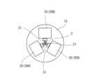
図3は、外科手術システム100の支持ブロック15への手術アセンブリ20の配置構成を示す図であり、中心軸Cの延在方向から支持ブロック15を見た図である。 FIG. 3 is a diagram showing the arrangement configuration of the
手術装置支持部14aには、複数の手術アセンブリ20を纏めて支持する支持ブロック15が設けられている。本実施の形態において、複数の手術アセンブリ20は、手術器具28を有する2つの手術アセンブリ20Aと、内視鏡カメラユニット33を有する1つの手術アセンブリ20Bとを含む。これら3つの手術アセンブリ20は、図3に示すように、中心軸Cを中心とする円周方向に並んで配置されている。 A
そして、支持フレーム14の中心軸Cを中心とする円周方向における姿勢が変更されると、エントリーガイド30及び手術装置支持部14aに支持された器具マニピュレータ21の中心軸Cを中心とする円周方向における姿勢も変更される。ポジショナ10がエントリーガイド30の中心軸を中心とする円周方向に回動可能にエントリーガイド30を支持するエントリーガイド支持構造である。 Then, when the attitude in the circumferential direction about the central axis C of the
なお、「近位」又は「近位に」という用語は、システム運動の運動連鎖に沿うポジショナ10により近い或いはシステム運動の運動連鎖に沿う運動の遠隔中心(又は手術部位)から更に離れる物体又は要素を一般的な方法において記載するために用いられる。同様に、「遠位」又は「遠位に」という用語は、システム運動の運動連鎖に沿うポジショナ10から更に離れる或いはシステム運動の運動連鎖に沿う運動の遠隔中心(又は手術部位)により近い物体又は要素を一般的な方法において記載するために用いられる。 It should be noted that the terms "proximal" or "proximal" refer to objects or elements closer to the
(手術アセンブリ20A)
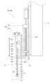
図4は、外科手術システム100の手術器具28を有する手術アセンブリ20Aの一例を示す側面図である。図5は、外科手術システム100の手術支援ロボット1の遠位端を示す斜視図である。(
FIG. 4 is a side view of an exemplary
図4に示す手術アセンブリ20Aは、遠位端に手術器具28が設けられた器具マニピュレータ21と、器具マニピュレータ21と連結され、器具マニピュレータ21を駆動する駆動ユニット22とを備える。 The
器具マニピュレータ21は、ベース23、細長い中空シャフト状のシャフト26、リスト27、及びエンドエフェクタとしての手術器具28が、近位から遠位に向かってこの順に連なっている。なお、「連なる」とは、2つのものが直接接続されている場合のみならず、2つのものの間に他のものが介在し、間接的に接続されている場合も含む。ベース23、シャフト26、リスト27、及び手術器具28は一体的に構成されている。 The
ベース23は、後述する第2サブ駆動ユニット22Bと脱着可能に接続されるコネクタであり、内部に後述する従動側プーリ25a、伝動ワイヤ25b等の伝動ユニットを収容する筐体である。 The
シャフト26は、剛性を有する管で構成され、近位端がベース23に取り付けられ、その中心軸Lが一直線に延びる。そして、図5に示すように、シャフト26は器具マニピュレータ挿通孔30Aに挿通され、シャフト26は、器具マニピュレータ挿通孔30Aに対して、この挿通孔が延びる方向に移動可能となっている。また、シャフト26の外周面は、横断面が円形に形成され、器具マニピュレータ挿通孔30Aに対して器具マニピュレータ挿通孔30Aの中心軸、すなわちシャフト26の中心軸Lを中心とする円周方向に回動可能となっている。なお、器具マニピュレータ挿通孔30Aの中心軸はエントリーガイド30の中心軸から偏心して位置しており、中心軸Cを中心とする円周方向にエントリーガイド30を回動させると、エントリーガイド30と共に手術アセンブリ20Aも中心軸Cを中心とする円周方向に回動する。シャフト26の内部空間は近位側においてベース23の内部空間と接続され、遠位側においてリスト27と接続され、ベース23からリスト27に向かって延びる後述する伝動ワイヤ25bがシャフト26の内部空間に位置している。 The
図4及び図5に示すように、リスト(手首構造)27は、近位端がシャフト26の遠位端に連なる。リスト27は、例えば中心軸Lを中心とする径方向への曲げ動作を行う関節である近位側曲げ関節61及び遠位側曲げ関節62と、中心軸Lを中心とする円周方向へのねじり動作を行う手首関節63を含み、後述する手術アセンブリ20Aの並進運動及び回転運動の少なくとも一部を担う。近位側曲げ関節61、遠位側曲げ関節62、手首関節63は、この順に近位から遠位に向かって連なっている。また、隣り合う関節は、連結セクション64によって連結されている。近位側曲げ関節61、遠位側曲げ関節62、及び手首関節63は後述する伝動ワイヤ25bの引力及び/又は張力によって作動する。 As shown in FIGS. 4 and 5, a wrist (wrist structure) 27 joins the distal end of
手術器具28は、手首関節63に連なる器具であり、例えば鉗子である。鉗子は、後述する伝動ワイヤ25bの引力及び/又は張力によって開閉する。なお、手術器具28はその動作によって中心軸Lを中心とする径方向への曲げ動作を行う。鉗子、把持器、鋏、ステープラ、針保持器、及び電気メスなどの外科器具であって良い。また、手術器具28は、電子外科電極、トランスデューサ、センサなどの電気的に駆動される機器であってもよい。また、手術器具28は、吸入、ガス注入、洗浄、処理流体、アクセサリ導入、生検摘出などのための流体を供給するノズルであってもよい。 The
そして、器具マニピュレータ21は、更に、駆動ユニット22の駆動力を伝達する伝動ユニットを有する。伝動ユニットは、ベース23に設けられた従動側プーリ25aを有する。従動側プーリ25aは、例えば、リスト27や手術器具28の作動部に対応して複数設けられている。従動側プーリ25aは、後述する対応する主動側プーリ44aと係脱可能に接続され、両プーリが係合することによって主動側プーリ44aの回動に従動し、主動側プーリ44aの駆動力が従動側プーリ25aに伝達される。このように、駆動ユニット22に対して器具マニピュレータ21は着脱可能に構成されているので、器具マニピュレータ21の滅菌、交換を容易に行うことができる。そして従動側プーリ25aには、伝動ワイヤ25bが取り付けられ、従動側プーリ25aを回動させることによって、伝動ワイヤ25bに引力及び/又は張力がかかるように構成されている。この伝動ワイヤ25bは、シャフト26の中を通ってリスト27の対応する関節及び手術器具28まで延び、従動側プーリ25aとこの従動側プーリ25aに対応する要素とを接続し、伝動ワイヤ25bの引力をこの対応する要素に伝達する。このような機構は、例えば、ここに参照として援用する、国際公開第2017/006376号に記載されている。但し、上記構成に限定されず、公知の機構を用いてもよい。 And the
駆動ユニット22は、手術器具28を移動させ且つ手術器具28の姿勢を変更させるユニットであり、第1サブ駆動ユニット22A及び第2サブ駆動ユニット22Bを含む。なお、以下では、手術器具28を移動させること及び手術器具28の姿勢を変更させることを、単に、手術器具28を動作させるということがある。 The
第1サブ駆動ユニット22Aは、シャフト26の中心軸Lを中心とする円周方向に器具マニピュレータ21を回動させ、且つ中心軸Lが延びる方向に器具マニピュレータ21を並進させる。第1サブ駆動ユニット22Aは、図2に示すように、回転ドライバアセンブリ41と、並進ドライバアセンブリ42とを有する。 The first
回転ドライバアセンブリ41は、器具マニピュレータ21及び第2サブ駆動ユニット22Bを一体的に中心軸Lを中心とする円周方向に回動可能に支持し且つ駆動する機構である。回転ドライバアセンブリ41は、サーボモータ等のアクチュエータ41aを有し、このアクチュエータ41aの出力軸にはギアトレインを介して第2サブ駆動ユニット22Bが中心軸L周りに回動可能に連なる。これにより、アクチュエータ41aの駆動力によって、器具マニピュレータ21及び第2サブ駆動ユニット22Bが駆動ユニット22に対して中心軸Lを中心とする円周方向に回動する。 The
並進ドライバアセンブリ42は、支持ブロック15に取り付けられ、器具マニピュレータ21、第2サブ駆動ユニット22B及び回転ドライバアセンブリ41を一体的に中心軸Lが延びる方向に並進可能に支持し且つ駆動する機構である。並進ドライバアセンブリ42は、サーボモータ等のアクチュエータを有するボールねじ機構42aと、中心軸Lが延びる方向に回転ドライバアセンブリ41を案内するリニアガイド42bを有する。そして、ボールねじ機構42aの駆動力によって、器具マニピュレータ21が駆動ユニット22に対して中心軸Lが延びる方向に移動する。並進ドライバアセンブリ42は回転ドライバアセンブリ41の近位側に連なっているが、これに限られるものではなく、これに代えて、並進ドライバアセンブリ42が回転ドライバアセンブリ41の遠位側に連なっていてもよい。 The
第2サブ駆動ユニット22Bは、第1サブ駆動ユニット22Aの遠位側に連なり、第1サブ駆動ユニット22Aと器具マニピュレータ21との間に介在する。第2サブ駆動ユニット22Bは、その駆動力によってリスト27及び手術器具28を動作させる。本実施の形態において、リスト27の各関節及び手術器具28の動作部位に対応して設けられたサーボモータ等のアクチュエータ44を有する。アクチュエータ44の出力軸は対応して設けられた主動側プーリ44aと連結されている。 The second
このように、手術アセンブリ20Aは、器具マニピュレータ21全体の並進運動及び回転運動、リスト27の関節の運動、並びに手術器具28の動作の組合せによって、予め定義された手術支援ロボット側3次元直交座標系におけるX軸、Y軸、Z軸の各軸方向への手術器具28の並進運動及びX軸、Y軸、Z軸の各軸を中心とする円周方向への手術器具28の回転運動が実現され、所定の基準点に対して手術器具28を並進運動及び回転運動させる。この並進運動及び回転運動を実現する構成が器具マニピュレータアームであり、本実施の形態においては、駆動ユニット22、ベース23、シャフト26、リスト27、手術器具28、及び伝動ユニットを含む。また、上述の通り、手術アセンブリ20Aは、器具マニピュレータ21の全体の並進、器具マニピュレータ21の全体の回転、リスト27の3つの関節、手術器具28の曲げ動作を行う機構の、互いに独立した6つの駆動関節を有し、6自由度で動作するマニピュレータであるが、これ以上の自由度で動作するマニピュレータであってもよい。なお、手術アセンブリ20Aの並進運動及び回転運動を実現する構成は上記の構成に限定されるものではない。 In this way, the
(手術アセンブリ20B)
図6は、内視鏡カメラユニット33を有する手術アセンブリ20Bの構成例を示す側面図である。図7は、カメラプローブ34(図5参照)と撮影領域Aとの関係を説明する図である。(
FIG. 6 is a side view showing a configuration example of a
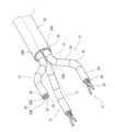
図5、図6に示すように、手術アセンブリ20Bは、内視鏡マニピュレータ31と、内視鏡マニピュレータ31と連結され内視鏡マニピュレータ31を駆動する駆動ユニット22とを備える。内視鏡マニピュレータ31はエントリーガイド30の内視鏡挿通孔30Bに挿通される。 As shown in FIGS. 5 and 6, the
内視鏡マニピュレータ31は、遠位端に内視鏡カメラユニット33が設けられている。内視鏡マニピュレータ31は、遠位端部に設けられた手術器具28を除いて、器具マニピュレータ21と実質的に同様の構成を有している。即ち、上記の器具マニピュレータ21の説明において、遠位端部に設けられた手術器具28を内視鏡カメラユニット33に読み替えることによって、内視鏡マニピュレータ31の構成を説明できる。また、駆動ユニットは、駆動ユニット22と実質的に同様の構成を有している。以上から、内視鏡カメラユニット33を除き、手術アセンブリ20Bの構成についての詳細な説明は、前述の手術アセンブリ20Aの説明を参照することによって省略する。なお、用語の混同を避けるため、手術アセンブリ20Bにおいて、器具マニピュレータアームは内視鏡マニピュレータアームという。 The
内視鏡カメラユニット33は、ステレオビデオカメラである一対のカメラプローブ34(34A、34B)、ライト35、及びレーザポインタ36を有する。レーザポインタ36は、前方の所定範囲内の任意の点にレーザ光を照射可能である。 The
図7に示すように、カメラプローブ34は、境界B1~B4によって囲まれる撮影領域Aを撮影し、画像データを取得する。この画像の左右方向に並ぶように一対のカメラプローブ34は配置されている。そして、一対のカメラプローブ34のうち、画像の左側に対応するカメラプローブ34Aは左方の後述する左表示部73Aに対応づけられ、画像の右側に対応するカメラプローブ34Bは後述する右表示部73Bに対応づけられている。 As shown in FIG. 7, the
〔コンソール7〕
図1に示すように、コンソール7は、外科手術システム100と術者(外科医)Yのインターフェースを構成し、手術支援ロボット1を操作するための装置である。コンソール7は、手術室内において手術台の傍らに又は手術台から離れて、或いは、手術室外に設置されている。[Console 7]
As shown in FIG. 1 , the
コンソール7は、術者Yからの動作指令の入力を受け付けるための操作用マニピュレータアーム71及び複数の操作用ペダル72を含む操作具と、内視鏡カメラユニット33で撮像された画像を表示するディスプレイモジュール73とを含む。操作用マニピュレータアーム71は、術者Yが動作指令を入力する際に把持する操作杆71aが先端に設けられ、基端がコンソール7に支持されている。そして、操作杆71aから基端に向かって複数の関節(図示略)が連なり、これら複数の関節の動作によって操作杆71aを3次元の動作領域内で移動させることができ、且つ操作杆71aの姿勢を変更することができるようになっている。すなわち、操作杆71aは、並進3自由度、回転3自由度を有する。そして、関節に操作杆71aの移動動作や姿勢変更動作によって生じる関節の動きを検知するセンサが設けられ、操作杆71aの位置及び姿勢は、コントローラ3によって、各関節のセンサが検知した関節の動きを組み合わせることによって、算出される。そして、操作杆71aに入力された動作指令が手術アセンブリ20Aに対する動作指令である器具動作指令であるのか、それとも手術アセンブリ20Bに対する動作指令である内視鏡動作指令であるのかは、操作用ペダル72に含まれる操作対象選択ペダル(図示略)によって選択、決定される。 The
図8は、ディスプレイモジュール73の構成例を示す図である。 FIG. 8 is a diagram showing a configuration example of the
図1及び図8に示すように、ディスプレイモジュール73は、術者Yの両目にそれぞれ対応する左右一対の表示部(表示領域)73A、73Bを有する。そして、左表示部73Aには一対のカメラプローブ34のうち一方のカメラプローブ34が撮影した画像が表示され、右表示部73Bには他方のカメラプローブ34が撮影した画像が表示される。表示部には画像の境界B1~B4(図7参照)がそれぞれ表示部の上下左右の境界上に位置するように表示される。これにより、術者Yは、患者Xの体腔の内部を立体視することができる。そして、術者Yは、ディスプレイモジュール73で患部を立体視しながら、操作具を操作することによって、手術器具28を動作させる器具動作指令、及び内視鏡カメラユニット33を動作させる内視鏡動作指令を入力する。 As shown in FIGS. 1 and 8, the
また、コンソール7は、コンソールコントローラ70を有し、このコンソールコントローラ70は、操作具によって入力された動作指令(器具動作指令、内視鏡動作指令)を受け付け、コントローラ3へ送信する。 The
また、ディスプレイモジュール73は、表示部において表示される画像に文字列、アイコンを重畳的に表示する。したがって、ディスプレイモジュール73は、術者Yに対する情報の報知を行う報知部としての機能も有している。 The
〔コントローラ3〕
図2に示すように、コントローラ3は、コンソールコントローラ70と通信可能に接続されている。コントローラ3は、コンソールコントローラ70を介して受け付けた動作指令に応答して手術アセンブリ20を動作させる。[Controller 3]
As shown in FIG. 2, the
コントローラ3は、いわゆるコンピュータであって、CPU等の演算処理部、ROM、RAM等の記憶部を有している(いずれも図示せず)。記憶部には、演算処理部が実行するプログラム、各種固定データ等が記憶されている。各種固定データには、後述する並進倍率値、回転倍率値、進入規制境界BP、第1規制対象区間P1、第2規制対象区間P2、第1進出限界位置L1を含む器具マニピュレータ21の動作可能範囲、第2進出限界位置L2を含む内視鏡マニピュレータ31の動作可能範囲が含まれる。演算処理部は、コンソール7を含む他の装置とのデータ送受信を行う。また、演算処理部は、各種センサからの検出信号の入力や各制御対象への制御信号の出力を行う。コントローラ3では、記憶部に記憶されたプログラム等のソフトウェアを演算処理部が読み出して実行することにより、後述するコントローラ3としての機能を実現するための処理が行われる。なお、コントローラ3は単一のコンピュータによる集中制御により各処理を実行してもよいし、複数のコンピュータの協働による分散制御により各処理を実行してもよい。また、コントローラ3は、マイクロコントローラ、プログラマブルロジックコントローラ(PLC)等から構成されていてもよい。コントローラ3は、ポジショナ制御部51、器具制御部52、内視鏡制御部53、及び表示制御部54を含む。ポジショナ制御部51、器具制御部52、内視鏡制御部53、及び表示制御部54は、記憶部に格納された所定の制御プログラムを演算処理部が実行することにより実現される機能ブロックである。 The
ポジショナ制御部51、器具制御部52、及び内視鏡制御部53は、増幅回路などを介してサーボモータと接続されたサーボ制御部(図示略)を含む。そして、ポジショナ制御部51は、エントリーガイド30を所定の位置及び姿勢に位置決めするように、各サーボモータに附帯する回転センサで検出された回転位置に基づいて、各関節の駆動部を動作させる。器具制御部52は、器具動作指令に従って手術アセンブリ20Aが動作するように、各サーボモータに附帯する回転センサで検出された回転位置に基づいて、駆動ユニット22の駆動部を制御する。また、手術器具28の動作を制御する。内視鏡制御部53は、内視鏡動作指令に従って手術アセンブリ20Bが動作するように、各サーボモータに附帯する回転センサで検出された回転位置に基づいて、駆動ユニット22の駆動部を制御する。また、内視鏡カメラユニット33の動作を制御する。表示制御部54は、カメラプローブ34が撮影した画像を処理してディスプレイモジュール73に表示する。 The
コントローラ3は、操作用マニピュレータアーム71の検知部が検知した操作杆71aの動作に基づき、コンソール側3次元直交座標系における操作杆71aの位置及び姿勢の変化、すなわち、コンソール側3次元直交座標系におけるX軸、Y軸、Z軸の各軸方向への操作杆71aの並進運動の並進量、及びX軸、Y軸、Z軸のうち1以上の軸を中心とする円周方向への操作杆71aの回転運動の回転量を算出する。そして、操作対象選択ペダルによって手術アセンブリ20Aが選択されているときは、コントローラ3は、これら並進量及び回転量を器具動作指令として取り扱い、一方で操作対象選択ペダルによって手術アセンブリ20Bが選択されているときは、これら並進量及び回転量を内視鏡動作指令として取り扱う。そして、コントローラ3は、コンソール側3次元直交座標系における操作杆71aの位置及び姿勢の変化を、手術支援ロボット側3次元直交座標系における操作対象(すなわち手術器具28及び内視鏡カメラユニット33)の位置及び姿勢の変化に変換し、操作対象に対応づける。そして、操作対象の位置及び姿勢が操作杆71aの位置及び姿勢の変化に対応して変化するように、器具制御部52及び内視鏡制御部53がそれぞれ手術アセンブリ20A及び手術アセンブリ20Bの動作を制御する。すなわち、コントローラ3は、操作対象が操作杆71aの並進運動の並進量に対応して動作するように操作対象を並進させ、且つ操作杆71aの回転運動の回転量に対応して操作対象を回転させる。 The
〔外科手術システム100の動作例〕
まず、コントローラ3は、コンソール7で受け付けたエントリーガイド30の位置決め指令に応答して、患者Xの体表に留置されたカニューレに対しエントリーガイド30が所定の位置及び姿勢に位置決めされるように、ポジショナ10を動作させる。エントリーガイド30が位置決めされると、複数の手術アセンブリ20も従動して位置決めされる。[Example of Operation of Surgical Operation System 100]
First, the
また、例えば、コントローラ3は、コンソール7で受け付けた動作指令に応答して、内視鏡カメラユニット33及び手術器具28が患者Xの体腔へ挿入されるように、駆動ユニット22の並進ドライバアセンブリ42を動作させる。 Also, for example, the
ここで、コントローラ3は、術者Yがコントローラ3に入力した器具動作指令及び内視鏡動作指令に種々の修正を加えて器具マニピュレータ21及び内視鏡マニピュレータ31を動作させる。これらの修正処理について以下詳述する。 Here, the
(スケール変更処理)
コントローラ3は、術者Yの器具動作指令の動作量を調整して器具マニピュレータ21及び内視鏡マニピュレータ31を動作させるスケール変更処理を行う。(Scale change processing)
The
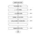
図9は、外科手術システム100の、スケール変更処理の一例を示すフローチャートである。 FIG. 9 is a flow chart illustrating an example of scale change processing of
図9に示すように、まず、コントローラ3は、操作対象選択ペダルによって手術アセンブリ20Aが選択されている状態において、操作用マニピュレータアーム71の検知部が検知したコンソール側3次元直交座標系におけるX軸、Y軸、Z軸の各軸方向への操作杆71aの並進量に所定の並進倍率値を乗算して手術器具28の実並進量を算出する(ステップS11)。並進倍率値は1未満の値であり、出力が入力よりも小さくなるようになっている。 As shown in FIG. 9, first, the
また、コントローラ3は、操作用マニピュレータアーム71の検知部が検知したコンソール側3次元直交座標系におけるX軸、Y軸、Z軸の各軸を中心とする円周方向への操作杆71aの回転量に所定の回転倍率値を乗算して手術器具28の実回転量を算出する(ステップS12)。回転倍率値は、1以上の値であり、入力と出力が同じか、又は出力が入力よりも大きくなるようになっている。このように、回転倍率値は、並進倍率値よりも大きい値に設定されている。 In addition, the
そして、コントローラ3は、コンソール側3次元直交座標系に対応する手術支援ロボット側3次元直交座標系において、手術器具28が、実並進量並進させた目標位置において、実回転量移動させた目標姿勢をとるように、駆動ユニット22の動作内容を決定し、この決定した動作内容に従って手術器具28を動作させる(ステップS13)。 Then, the
このように、コントローラ3は、術者Yが入力した並進量に1以下の倍率値を乗算して、実際の手術器具28の実並進量を算出しているので、操作用マニピュレータアーム71の動作が縮小されて、手術器具28が動作する。よって、術者Yは、手術器具28を精密に移動させることができる。一方で、コントローラ3は、術者Yが入力した回転量に1以上の倍率値を乗算して、実際の手術器具28の実回転量を算出しているので、操作用マニピュレータアーム71の動作が拡大されて手術器具28が動作する、よって、術者Yは、手術器具28を大きく旋回させる動作等において、大きく体全体を動かして操作用マニピュレータアーム71を操作する必要がなく、術者Yは手術器具28の姿勢を速やかに変更することができる。これによって、外科手術システム100の操作性を向上させることができる。 In this manner, the
(境界進入規制処理)
また、コントローラ3は、カメラプローブ34が撮影する画像の向きに対して、画像に映り込む器具マニピュレータ21の姿勢を一定範囲に規制する境界進入規制処理を行う。(Boundary entry control processing)
In addition, the
図10は、外科手術システム100の境界進入規制処理の一例を示すフローチャートである。図11A及び図11Bは、外科手術システム100の、境界進入規制処理の動作例を示す図であり、ディスプレイモジュール73に表示される画像を示す図である。 FIG. 10 is a flow chart showing an example of boundary entry regulation processing of the
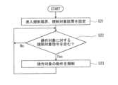
まず、図10に示すように、コントローラ3は、撮影領域Aの上側境界B1を進入規制境界BPに設定する。進入規制境界BPは、撮影領域Aの上側の境界であり、左右の表示部73A、73Bには進入規制境界BPが上側に位置するように表示される。なお、進入規制境界BPは、左側境界B3及び右側境界B4に及んでいてもよい。また、コントローラ3は、器具マニピュレータ21の遠位端側の部位にそれぞれ規制対象区間SP(図4参照)を設定する(ステップS21)。 First, as shown in FIG. 10, the
次に、コントローラ3は、操作対象を動作させている間、術者Yが入力した動作指令に、器具マニピュレータ21の規制対象区間SPが進入規制境界BPに進入するように操作対象を動作させる指令である規制対象指令が含まれるか否かを判定する(ステップS22)。 Next, while the operation target is being operated, the
すなわち、操作対象が器具マニピュレータ21である場合、図11Aに示すように、コントローラ3は、器具動作指令に、器具マニピュレータ21の規制対象区間SPが進入規制境界BPに進入するように手術器具28を動作させる指令である規制対象指令が含まれるか否かを判定する。また、操作対象が内視鏡マニピュレータ31である場合、図11Bに示すように、コントローラ3は、内視鏡動作指令に、規制対象区間SPが進入規制境界BPに進入して交差するようにカメラプローブ34を動作させる指令である第2規制対象指令が含まれるか否かを判定する。すなわち、内視鏡マニピュレータ31の回転によってカメラプローブ34の位置が移動して規制対象区間SPが移動し、その結果、器具マニピュレータ21の規制対象区間SPが進入規制境界BPに進入するように内視鏡マニピュレータ31を制御する指令が含まれるか否かを判定する。 That is, when the operation target is the
そして、コントローラ3は、規制対象指令が含まれると判定すると(ステップS22においてYes)、動作指令に含まれる動作量のうち、規制対象区間SPが進入規制境界BPに進入して交差するように操作対象を動作させる方向成分の動作量を0に設定し、この方向への操作対象の動作を規制する。一方、規制対象指令が含まれないと判定すると(ステップS22においてNo)、ステップS22の判定を再び行う。 Then, when the
これによって、カメラプローブ34が撮影した画像において、器具マニピュレータ21が延びる方向を術者Yの腕が延びる方向と同等に維持することができ、外科手術システム100の操作性を向上させることができる。 Accordingly, in the image captured by the
なお、器具マニピュレータ21が撮影領域Aの上側の境界に進入しないように器具マニピュレータ21及び内視鏡マニピュレータ31について可動範囲を設定し、コントローラ3が動作指令に可動範囲を逸脱する指令が含まれると判定すると、逸脱する方向への動作を規制してもよい。また、動作の規制は、メカニカルストッパ等によって機械的に行ってもよく、ソフトリミット等によってソフトウェア的に行ってもよい。 If the movable range of the
(進出規制処理)
図12は、外科手術システム100の、進出規制処理の一例を示すフローチャートである。図13は、外科手術システム100の進出規制処理における動作例を示す図である。(Exit restriction processing)
FIG. 12 is a flow chart showing an example of an entry restriction process of the
また、コントローラ3は、更に器具マニピュレータ21及び内視鏡マニピュレータ31の中心軸Cが延びる方向への並進を規制する進出規制処理を行う。 In addition, the
まず、コントローラ3は、器具マニピュレータ21及び内視鏡マニピュレータ31の動作可能範囲を設定する(ステップS31)。この動作可能範囲には、中心軸Cが延びる方向における器具マニピュレータ21及び内視鏡マニピュレータ31の移動可能範囲が含まれる。図13に示すように、内視鏡マニピュレータ31の移動可能範囲(第2移動可能範囲)の遠位端側の限界位置である第2進出限界位置L2は、中心軸Cが延びる方向において器具マニピュレータ21の移動可能範囲(第1移動可能範囲)の遠位側の限界位置である第1進出限界位置L1よりも近位端側に位置するように設定される。 First, the
次に、コントローラ3は、操作対象を動作させている間、術者Yが入力した動作指令に動作可能範囲を逸脱する方向へ操作対象を動作させる指令が含まれているか否かを判定する(ステップS32)。 Next, while the operation target is moving, the
そして、コントローラ3は、動作指令に動作可能範囲を逸脱する方向へ操作対象を動作させる指令が含まれていると判定すると(ステップS32においてYes)、動作指令に含まれる動作量のうち、動作可能範囲を逸脱する方向へ操作対象を動作させる方向成分の動作量を0に設定し、この方向への操作対象の動作を規制する(ステップS33)。この処理において、コントローラ3は、中心軸Cが延びる方向において、器具マニピュレータ21の移動可能範囲(第1移動可能範囲)の遠位側の限界位置である第1進出限界位置L1に達したと判定すると、更に遠位へ移動する動作を規制する。一方、動作指令に動作可能範囲を逸脱する方向へ操作対象を動作させる指令が含まれていないと判定すると(ステップS32においてNo)、ステップS32の判定を再び行う。 Then, when the
ここで、第2進出限界位置L2は、中心軸Cが延びる方向において、第1進出限界位置L1よりも近位端側に位置するよう設定されているので、これによって、手術器具28の動作をモニターするためのカメラプローブ34の視界から手術器具28が外れて、手術器具28を見失うことを効果的に防止することができる。これによって、外科手術システム100の操作性を向上させることができる。 Here, since the second advance limit position L2 is set to be located closer to the proximal end than the first advance limit position L1 in the direction in which the central axis C extends, the operation of the
(初期動作規制処理)
更に、コントローラ3は、器具マニピュレータ21及び内視鏡マニピュレータ31のリスト27がエントリーガイド30の遠位端を通過するまでは、リスト27の動作を規制する初期動作規制処理を行う。この処理は、手術器具28及びカメラプローブ34を患者Xの体腔に送り込む際に行われる。(Initial operation regulation processing)
Furthermore, the
まず、コントローラ3は、中心軸Cが延びる方向(器具マニピュレータ21が延びる方向)において操作対象のリスト27がエントリーガイド30の遠位端よりも遠位に位置するか否かを判定する。すなわち、コントローラ3は、中心軸Cが延びる方向において、リスト27がエントリーガイド30の遠位端の近位側又はエントリーガイド30の遠位端上に位置するか否かを判定する。 First, the
そして、中心軸Cが延びる方向における器具マニピュレータ21のリスト27の近位端がエントリーガイド30の遠位端よりも遠位に位置していないと判定すると、動作指令に含まれる動作量のうち、中心軸Cが延びる方向成分以外の方向成分の動作量を0に設定し、この方向以外への操作対象の動作を規制する。そして、コントローラ3は、中心軸Cが延びる方向において操作対象のリスト27がエントリーガイド30の遠位端よりも遠位に位置すると判定するまで、繰り返し当該判定を行い、中心軸Cが延びる方向において操作対象のリスト27がエントリーガイド30の遠位端よりも遠位に位置すると判定すると、処理を終了する。 Then, when it is determined that the proximal end of the
これによって、器具マニピュレータ21及び内視鏡マニピュレータ31を速やかに患者Xの体腔に送り込むことができ、外科手術システム100の操作性を向上させることができる。 As a result, the
(体壁干渉防止処理)
図14は、外科手術システム100の、体壁干渉防止処理の一例を示すフローチャートである。図15は、外科手術システム100の、体壁干渉防止処理における体壁形状算出処理の一例を示すフローチャートである。図16は、外科手術システム100の、体壁干渉防止処理における動作例を示す図である。図17は、外科手術システム100の、体壁干渉防止処理における体壁形状算出処理を説明する図である。(Body wall interference prevention treatment)
FIG. 14 is a flowchart showing an example of body wall interference prevention processing of
更に、コントローラ3は、器具マニピュレータ21及び内視鏡マニピュレータ31と患者Xの体腔を形成する体壁との干渉を防止する体壁干渉防止処理を所定の時間間隔で繰り返し行う。 Furthermore, the
まず、図14に示すように、コントローラ3は、カメラプローブ34が取得した画像に基づき、患者Xの体腔からみた、体壁の3次元形状を表す3次元マップを算出する(ステップS41)。 First, as shown in FIG. 14, the
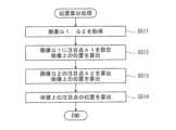
3次元マップは、例えば図15に示す、以下の処理によって算出される。コントローラ3は、まず、患者Xの体腔に位置させた内視鏡マニピュレータ31のレーザポインタ36からレーザ光を照射する(ステップS411)。レーザ光の照射方向はランダムに選択されてもよい。次に、コントローラ3は、一対のカメラプローブ34によって一対の画像G1,G2を取得する(ステップS412)。次に、この取得した一対の画像G1,G2に記録されたレーザ光の照射部位をそれぞれの画像の注目点A1,A2に設定する(ステップS413)。図16に示すように、カメラプローブ34A及びカメラプローブ34Bの位置の違いから、画像G1の注目点A1の位置と、画像G2の注目点A2の位置は、異なって記録される。なお、一対の画像の注目点はパターンマッチング(詳細は後述)によって設定してもよい。そして、図17に示すように、一方の画像の注目点A1と他方の画像の注目点A2との相対的な位置関係に基づいて手術支援ロボット側3次元直交座標系における体壁上の注目点ARの座標を算出(ステップS414)する。そして、上記ステップS411~S414を所定回数繰り返す。上述の通りレーザ光の照射方向はランダムに選択され、座標算出処理を繰り返し実行することによって設定される注目点は散点的なものとなる。次に、コントローラ3は、散点的な注目点の座標を通る面を算出し、患者Xの体腔を形成する体壁の形状を算出する(ステップS415)。このように、一対のカメラプローブ34は、患者Xの体腔を形成する体壁の形状を検出するための情報を検知する(体壁形状検知部)。 A three-dimensional map is calculated by the following process shown in FIG. 15, for example. The
次に、コントローラ3は、ステップS415において算出した体壁面S1から体腔側に所定距離オフセットした進入規制境界面S2を算出する(ステップS42)。進入規制境界面S2と体壁面S1との間の領域が進入禁止領域である。 Next, the
次に、コントローラ3は、操作対象が進入規制境界面S2よりも体壁面S1側に進入したか否か、すなわち器具マニピュレータ21が進入禁止領域RSに進入したか否かを判定する(ステップS43)。 Next, the
そして、コントローラ3は、進入禁止領域RSに進入したと判定すると(ステップS43においてYes)、動作指令に含まれる動作量のうち、操作対象を体壁面に向かって動作させる方向成分の動作量を0に設定し、この方向への操作対象の動作を規制する。また、コントローラ3は、ディスプレイモジュール73に器具マニピュレータ21が進入禁止領域RSに進入したことを報知するための情報を表示する。なお、コントローラ3は、進入禁止領域RSに進入していないと判定すると(ステップS43においてNo)、ステップS44をスキップする。 Then, when the
これによって、操作対象である器具マニピュレータ21及び内視鏡マニピュレータ31と体壁との干渉を防止することができる。 As a result, interference between the
(位置変化相殺処理)
図18は、外科手術システム100の、位置変化相殺処理の一例を示すフローチャートである。図19は、外科手術システム100の、位置変化相殺処理における位置算出処理の一例を示すフローチャートである。(Position change offset processing)
FIG. 18 is a flow chart showing an example of position change cancellation processing of
更に、コントローラ3は、例えば患者Xが姿勢を変えたことなどに起因してエントリーガイド30が予期せず動き、手術器具28及びカメラプローブ34が移動したときに、手術器具28及びカメラプローブ34の位置の変化を相殺する方向に手術器具28及びカメラプローブ34を動かす位置変化相殺処理を行う。 Furthermore, when the
まず、図18に示すように、コントローラ3は、所定時間、内視鏡動作指令が入力されていないと判定すると、患者Xの体腔を形成する体壁上に設定した注目点AR(図7参照)の位置を算出し、この注目点ARの位置に基づいて手術器具28及びカメラプローブ34の位置を算出する。そして、算出した手術器具28及びカメラプローブ34の位置を初期位置に設定する(ステップS51)。注目点ARは、カメラプローブ34が取得した画像に基づき設定される。 First, as shown in FIG. 18, when the
注目点ARの位置は、以下の通りパターンマッチングにより算出する。まず、コントローラ3は、一対のカメラプローブ34によって一対の画像G1,G2を取得する(ステップS511)。次に、この取得した一対の画像のうち、一方の画像G1に注目点A1を設定し、注目点A1の画像上の位置を算出する(ステップS512)。次に、他方の画像G2に記録された体壁上において注目点A1の場所と同じ場所を一対の画像G1,G2のパターンマッチングによって決定し、これを注目点A2に設定する。そして、注目点Bの画像G2上の位置を算出する(ステップS513)。そして、注目点A1と注目点A2との相対的な位置関係に基づいて、注目点A1及び注目点A2に対応する体壁上の注目点ARを算出する(ステップ514)。この座標の算出方法は、上記体壁干渉防止処理において説明した体壁形状算出処理における方法と同じ方法によって行うことができる。なお、これ以降の処理は、内視鏡動作指令が入力されると中止される。 The position of the attention point AR is calculated by pattern matching as follows. First, the
次に、コントローラ3は、所定のサンプリング周期経過後、注目点ARの位置を算出し、この注目点ARの位置に基づいて手術器具28及びカメラプローブ34の位置を算出する(ステップS53)。そして、算出した手術器具28及びカメラプローブ34の位置を現在位置に設定する(ステップS54)。 Next, the
次に、コントローラ3は、初期位置と現在位置とを比較し、初期位置に対して現在位置が所定の閾値以上に変化したか否かを判定する(ステップS55)。 Next, the
そして、コントローラ3は、初期位置に対して現在位置が所定の閾値以上に変化したと判定すると(ステップS55においてYes)、手術器具28及びカメラプローブ34を初期位置に向かって動作させる。また、コントローラ3は、表示部に現在位置が変化したことを報知するための情報を表示する。そして、内視鏡動作指令が入力されるまで、再びステップS53を行う。 When the
これによって、エントリーガイド30の位置が予期せず変化して、これにより手術器具28及びカメラプローブ34の位置が変化した場合であっても、手術器具28及びカメラプローブ34は、自動的に初期位置に復帰するので、術者の操作性への悪影響を緩和することができ、外科手術システム100の操作性を向上させることができる。また、エントリーガイド30の位置が変化したことを術者Yが認識することができる。 This ensures that even if the position of the
(実施の形態2)
以下では実施の形態2の構成、動作について、実施の形態1との相違点を中心に述べる。(Embodiment 2)
The configuration and operation of the second embodiment will be described below, focusing on the differences from the first embodiment.
図20は、実施の形態2に係る外科手術システムの手術支援ロボットの遠位端を示す斜視図である。 FIG. 20 is a perspective view showing the distal end of the surgical assistance robot of the surgical operation system according to
上記実施の形態1において、内視鏡マニピュレータ31は、エントリーガイド30の内視鏡挿通孔30Bの中心軸を中心とする円周方向に回動可能としている。 In
これに対し、本実施の形態において、内視鏡マニピュレータ231は、エントリーガイド230の内視鏡挿通孔230Bの中心軸を中心とする円周方向への内視鏡マニピュレータ231の回動を規制する回動規制構造を有する。 On the other hand, in the present embodiment, the
回動規制構造は、例えば、シャフト260の径方向に突出する鍔261と、内視鏡挿通孔230Bの内周面に形成された鍔261と係合する溝226とを含む。鍔261は、シャフト26に沿って延びる。また、内視鏡マニピュレータ31は手首関節63を有しない。更に、手術アセンブリ20Bの第1サブ駆動ユニット22Aは回転ドライバアセンブリ41を有さず、第2サブ駆動ユニット22Bは並進ドライバアセンブリ42に取り付けられている。 The rotation restricting structure includes, for example, a
このように、内視鏡マニピュレータ31は、エントリーガイド230に対して、エントリーガイド230の内視鏡挿通孔230Bの中心軸を中心とする円周方向への回動が規制されているので、エントリーガイド30及び器具マニピュレータ21に対する内視鏡の画像の向きを維持にすることができ、術者Yが手術器具28の位置を容易に認識することができる。これによって、外科手術システム100の操作性を向上させることができる。 As described above, the
また、実施の形態1において詳述した通り、器具マニピュレータ21は、エントリーガイド230に対して、エントリーガイド230の器具マニピュレータ挿通孔230Aの中心軸を中心とする円周方向へ回動可能となっているので、外科手術システム200の操作性を向上させることができる。 Further, as described in detail in
更に、実施の形態1において詳述した通り、支持フレーム14は、エントリーガイド30の中心軸(すなわち、中心軸C)を中心とする円周方向に回動可能であるので、エントリーガイド30及び器具マニピュレータ21に対する内視鏡の画像の向きを維持したまま、手術支援ロボット1の遠位端の姿勢を変更することができる。よって、外科手術システム200の操作性を向上させることができる。 Furthermore, as described in detail in
(実施の形態3)
以下では実施の形態3の構成、動作について、実施の形態1との相違点を中心に述べる。(Embodiment 3)
The configuration and operation of the third embodiment will be described below, focusing on differences from the first embodiment.
上記実施の形態において、外科手術システム100は、初期動作規制処理によって器具マニピュレータ21及び内視鏡マニピュレータ31のリスト27がエントリーガイド30の遠位端を通過するまでは、リスト27の動作を規制した。しかし、これに限られるものではなく、これに代えて、その作動によってリスト27に対応する従動側プーリ25a又は主動側プーリ44aの回動を規制し、その解除によって従動側プーリ25a又は主動側プーリ44aの回動を許容するブレーキを設けてもよい。 In the above embodiment,
上記説明から、当業者にとっては、本発明の多くの改良や他の実施形態が明らかである。従って、上記説明は、例示としてのみ解釈されるべきであり、本発明を実行する最良の態様を当業者に教示する目的で提供されたものである。本発明の精神を逸脱することなく、その構造及び/又は機能の詳細を実質的に変更できる。 From the above description many modifications and other embodiments of the invention will be apparent to those skilled in the art. Accordingly, the above description is to be construed as illustrative only and is provided for the purpose of teaching those skilled in the art the best mode of carrying out the invention. Substantial details of construction and/or function may be changed without departing from the spirit of the invention.
3 コントローラ
7 コンソール
20 手術アセンブリ
21 器具マニピュレータ
22 駆動ユニット
26 シャフト
27 リスト
28 手術器具
30 エントリーガイド
41 回転ドライバアセンブリ
42 並進ドライバアセンブリ
61 近位側曲げ関節
62 遠位側曲げ関節
63 手首関節
71 操作用マニピュレータアーム
100 外科手術システム3
Claims (17)
Translated fromJapaneseカメラプローブを有するカメラユニット、遠位側に前記カメラユニットが接続される内視鏡シャフトおよび前記内視鏡シャフトの近位側が接続される内視鏡ベースを有する内視鏡マニピュレータと、前記内視鏡ベースが着脱可能に接続され、前記内視鏡マニピュレータを並進運動及び回転運動させるための内視鏡駆動ユニットと、を備える内視鏡マニピュレータアームと、
前記内視鏡シャフトが挿通される内視鏡挿通孔および前記器具シャフトが挿通される器具挿通孔を有するエントリーガイドと、
前記手術器具に対する前記手術器具の並進運動の並進量及び回転運動の回転量を含む外科医の器具動作指令を受け付ける操作具を有するコンソールと、
前記器具マニピュレータアームを制御するコントローラと、を備え、
前記コントローラは、前記操作具が受け付けた前記手術器具の前記並進量に所定の並進倍率値を乗算して実並進量を算出し、該実並進量に対応して前記手術器具を動作させるように前記器具マニピュレータアームを制御し、且つ前記操作具が受け付けた前記手術器具の前記回転量に所定の回転倍率値を乗算して実回転量を算出し、該実回転量に対応して前記手術器具を動作させるように前記器具マニピュレータアームを制御し、
前記回転倍率値と前記並進倍率値は異なる値であり、
前記カメラプローブは、予め設定された進入規制境界を含む境界によって囲まれる撮影領域を撮影するように構成されており、
前記コンソールは、前記カメラプローブが撮影した画像を表示する表示領域を有するディスプレイモジュールを有し、前記ディスプレイモジュールは前記進入規制境界を前記表示領域の上側に位置させて前記カメラプローブが撮影した画像を表示し、
前記コントローラは、前記器具動作指令に前記器具マニピュレータの遠位端側に設定された規制対象区間が前記進入規制境界に進入するように前記手術器具を動作させる指令が含まれると判定すると、前記規制対象区間が前記進入規制境界に進入するように前記手術器具を動作させる方向への前記手術器具の動作を規制する、外科手術システム。an instrument manipulator having a surgical instrument, an instrument shaft to which the surgical instrument is connected on the distal side, and an instrument base to which the proximal side of the instrument shaft is connected; and the instrument base is detachably connected to translate the instrument manipulator. an instrument manipulator arm comprising: an instrument drive unit for moving and rotating;
an endoscope manipulator having a camera unit having a camera probe, an endoscope shaft to which the camera unit is connected on the distal side, and an endoscope base to which the proximal side of the endoscope shaft is connected; an endoscope manipulator arm detachably connected to a mirror base and comprising an endoscope drive unit for translating and rotating the endoscope manipulator;
an entry guide having an endoscope insertion hole through which the endoscope shaft is inserted and an instrument insertion hole through which the instrument shaft is inserted;
a console having an operation tool for receiving a surgeon's instrument operation command including a translational amount of translational movement and a rotational amount of rotational movement of the surgical instrument relative to the surgical instrument;
a controller that controls the instrument manipulator arm;
The controller calculates an actual translational amount by multiplying the translational amount of the surgical instrument received by the operating tool by a predetermined translational magnification value, and operates the surgical instrument in accordance with the actual translational amount. controlling the instrument manipulator arm, multiplying the amount of rotation of the surgical instrument received by the operating tool by a predetermined rotation magnification value to calculate an actual amount of rotation, and calculating the actual amount of rotation of the surgical instrument in accordance with the actual amount of rotation; controlling the instrument manipulator arm to operate
the rotation magnification valueand the translation magnification value aredifferent values;
The camera probe is configured to photograph an imaging area surrounded by a boundary including a preset entry restriction boundary,
The console has a display module having a display area for displaying an image captured by the camera probe, and the display module displays the image captured by the camera probe with the entry restriction boundary positioned above the display area. display and
When the controller determines that the instrument operation command includes a command to operate the surgical instrument so that the restricted section set on the distal end side of the instrument manipulator enters the entry restriction boundary, A surgical system that restricts movement of the surgical instrument in a direction that moves the surgical instrument such that a target section enters the entry restriction boundary.
前記コントローラは、前記内視鏡マニピュレータアーム動作指令に前記規制対象区間が前記進入規制境界に進入するように前記カメラプローブを動作させる指令が含まれると判定すると、前記規制対象区間が前記進入規制境界に進入するように前記カメラプローブを動作させる方向への前記カメラプローブの動作を規制するように前記内視鏡マニピュレータアームを制御する、請求項1または2に記載の外科手術システム。The operation tool receives a surgeon's endoscope manipulator arm operation command including a translation amount of translational movement and a rotational amount of rotational movement of the camera probe relative to the camera probe,
When the controller determines that the endoscope manipulator arm operation command includes a command to operate the camera probe so that the restricted section enters the entry restricted boundary, the controller determines that the restricted section enters the entry restricted boundary. 3. The surgical system of claim1 or 2 , wherein the endoscopic manipulator arm is controlled to constrain motion of the camera probe in a direction to move the camera probe to enter the endoscopic body.
前記エントリーガイドは、前記内視鏡挿通孔の中心軸を中心とする円周方向への前記内視鏡マニピュレータアームの回動を規制する回動規制構造を有する、請求項1~3の何れか1項に記載の外科手術システム。The console has a display module having a display area for displaying an image captured by the camera probe in a predetermined orientation,
4. The entry guide according to any one of claims1 to3 , wherein the entry guide has a rotation restricting structure that restricts rotation of the endoscope manipulator arm in a circumferential direction about the central axis of the endoscope insertion hole. 2. The surgical system of Claim 1.
前記第2移動範囲の遠位端側の限界は、前記第1移動範囲の遠位端側の限界よりも近位端側に位置する、請求項1~6の何れか1項に記載の外科手術システム。The controller controls the instrument manipulator arm so as to move the instrument shaft relative to the entry guide in a direction in which the instrument insertion hole extends within a predetermined first movement range, and moves the endoscope shaft to the controlling the endoscope manipulator arm so as to move the endoscope manipulator arm relative to the entry guide within a predetermined second movement range in the direction in which the endoscope insertion hole extends;
The surgical procedure according to any one of claims1 to6 , wherein the distal end side limit of the second range of motion is located closer to the proximal side than the distal end side limit of the first range of motion. surgical system.
前記手首構造は、遠位側曲げ関節および近位側曲げ関節を含む、請求項1~7の何れか1項に記載の外科手術システム。The instrument manipulator comprises: a wrist structure provided proximal to the surgical instrument and distal to the instrument shaft; and an instrument transmission unit for transmitting driving force of the instrument drive unit to the wrist structure. has
The surgical system of any one of claims1-7 , wherein the wrist structure includes a distal flexion joint and a proximal flexion joint.
前記器具マニピュレータは、作動により前記手首構造の動作を規制し且つ作動解除により前記手首構造の動作を許容するブレーキを有し、
前記コントローラは、前記器具シャフトが延びる方向において前記手首構造が前記エントリーガイドの遠位端の近位端側及び前記エントリーガイドの遠位端上に位置するときは前記ブレーキを作動させる、請求項1~7の何れか1項に記載の外科手術システム。The instrument manipulator includes a wrist structure proximal to the surgical instrument and distal to the instrument shaft for at least a portion of the translational and rotational movements of the surgical instrument. death,
the instrument manipulator has a brake that restricts movement of the wrist structure upon actuation and permits movement of the wrist structure upon deactuation;
2. The controller of claim1 , wherein the controller activates the brake when the wrist structure is proximal to and on the distal end of the entry guide in the direction of extension of the instrument shaft. 8. The surgical system according to any one of paragraphs 1 to7 .
前記コントローラは、前記器具シャフトが延びる方向において前記手首構造が前記エントリーガイドの遠位端の近位側及び前記エントリーガイドの遠位端上に位置するときは前記器具動作指令に含まれる前記手首構造の動作指令を無効化する、請求項1~7の何れか1項に記載の外科手術システム。The instrument manipulator has a wrist structure provided proximal to the surgical instrument, the movement of which causes at least part of the translational movement and the rotational movement of the surgical instrument,
The controller controls the wrist structure included in the instrument operation command when the wrist structure is located proximal to the distal end of the entry guide and on the distal end of the entry guide in the direction in which the instrument shaft extends. The surgical system according to any one of claims1 to7 , wherein the operation command of the is overridden.
前記内視鏡マニピュレータアームは、患者の体腔を形成する体壁の形状を検出するための情報を検知する体壁形状検知部を有し、
前記コントローラは、前記体壁形状検知部が検知した情報に基づいて前記体壁の形状を算出し、
算出した前記体壁の形状に基づいて進入禁止領域を設定し、
前記進入禁止領域に前記器具マニピュレータが進入したか否かを繰り返し判定し、前記進入禁止領域に前記器具マニピュレータが進入したと判定すると、前記報知部を制御して前記外科医に前記進入禁止領域への前記器具マニピュレータの進入を報知する、請求項1に記載の外科手術システム。A reporting unit for reporting information to the surgeon,
The endoscope manipulator arm has a body wall shape detection unit that detects information for detecting the shape of the body wall that forms the patient's body cavity,
The controller calculates the shape of the body wall based on the information detected by the body wall shape detection unit,
setting a no-entry area based on the calculated shape of the body wall;
It is repeatedly determined whether or not the instrument manipulator has entered the entry prohibition area, and when it is determined that the instrument manipulator has entered the entry prohibition area, the notification unit is controlled to notify the surgeon to the entry prohibition area. The surgical system of claim1 , wherein the surgical system signals entry of the instrument manipulator.
前記コントローラは、
前記一対のカメラプローブが撮影した画像に記録された前記体壁に散点的に複数の注目点を設定し、
各前記注目点について、前記一対のカメラプローブのうちの一方が撮影した画像である第1画像の前記注目点の位置と、前記一対のカメラプローブのうちの他方が前記第1画像と同時に撮影した画像である第2画像の前記注目点の位置との相対的な位置関係に基づいて所定の基準点に対する前記注目点の座標を算出し、
算出した複数の前記注目点の3次元座標に基づいて、前記体壁の形状を算出する、請求項11に記載の外科手術システム。The camera probes are a pair of camera probes arranged at a predetermined interval, the body wall shape detection unit is the pair of camera probes,
The controller is
setting a plurality of attention points in a scattered manner on the body wall recorded in the image captured by the pair of camera probes;
For each of the points of interest, the position of the points of interest in a first image taken by one of the pair of camera probes and the first image taken by the other of the pair of camera probes at the same time. calculating coordinates of the point of interest with respect to a predetermined reference point based on a relative positional relationship with the position of the point of interest in a second image, which is an image;
The surgical operation system according to claim11 , wherein the shape of the body wall is calculated based on the calculated three-dimensional coordinates of the plurality of points of interest.
前記コントローラは、前記第1画像及び前記第2画像の前記注目点を前記第1画像及び前記第2画像に記録された前記レーザ光の照射部位をそれぞれ前記第1画像及び前記第2画像の前記注目点に設定する、請求項12に記載の外科手術システム。The camera unit includes a laser pointer that emits laser light,
The controller converts the point of interest of the first image and the second image to the irradiated portion of the laser beam recorded in the first image and the second image, respectively. 13. The surgical system of claim12 , set to a point of interest.
前記カメラプローブは、所定の間隔で並ぶ一対のカメラプローブであり、
前記コントローラは、
前記一対のカメラプローブが撮影した画像に記録された患者の体腔を形成する体壁に注目点を設定し、
前記一対のカメラプローブのうちの一方が撮影した画像である第1画像の前記注目点の位置と、前記一対のカメラプローブのうちの他方が撮影した画像である第2画像の前記注目点の位置との相対的な位置関係に基づいて前記注目点に対する前記一対のカメラプローブの位置である初期位置を算出し、
前記第1画像の前記注目点の位置と、前記第2画像の前記注目点の位置との相対的な位置関係に基づいて前記注目点に対する前記一対のカメラプローブの位置である現在位置を繰り返し算出し、
前記初期位置に対して前記現在位置が所定の閾値以上に変化したか否かを判定し、
前記初期位置に対して前記現在位置が所定の閾値以上に変化したと判定すると、前記報知部を制御して前記現在位置の変化を報知する、請求項1に記載の外科手術システム。A reporting unit for reporting information to the surgeon,
The camera probes are a pair of camera probes arranged at a predetermined interval,
The controller is
setting a point of interest on a body wall forming a body cavity of the patient recorded in the image captured by the pair of camera probes;
A position of the point of interest in a first image taken by one of the pair of camera probes and a position of the point of interest in a second image taken by the other of the pair of camera probes. Calculate an initial position that is the position of the pair of camera probes with respect to the point of interest based on the relative positional relationship with
A current position, which is the position of the pair of camera probes with respect to the point of interest, is repeatedly calculated based on the relative positional relationship between the position of the point of interest in the first image and the position of the point of interest in the second image. death,
Determining whether the current position has changed from the initial position by a predetermined threshold or more,
The surgical operation system according to claim1 , wherein when it is determined that the current position has changed from the initial position by a predetermined threshold or more, the notification unit is controlled to notify the change of the current position.
カメラプローブを有するカメラユニット、遠位側に前記カメラユニットが接続される内視鏡シャフトおよび前記内視鏡シャフトの近位側が接続される内視鏡ベースを有する内視鏡マニピュレータと、前記内視鏡ベースが着脱可能に接続され、前記内視鏡マニピュレータを並進運動及び回転運動させるための内視鏡駆動ユニットと、を備える内視鏡マニピュレータアームと、
前記内視鏡シャフトが挿通される内視鏡挿通孔および前記器具シャフトが挿通される器具挿通孔を有するエントリーガイドと、
前記手術器具に対する前記手術器具の並進運動の並進量及び回転運動の回転量を含む外科医の器具動作指令を受け付ける操作具を有するコンソールと、
前記器具マニピュレータアームを制御するコントローラと、を備える外科手術システムの制御方法であって、
前記コントローラが、前記操作具が受け付けた前記手術器具の前記並進量に並進倍率値を乗算して実並進量を算出するステップと、
前記コントローラが該実並進量に対応して前記手術器具を動作させるように前記器具マニピュレータアームを制御するステップと、
前記コントローラが、前記操作具が受け付けた前記手術器具の前記回転量に回転倍率値を乗算して実回転量を算出するステップと、
前記コントローラが該実回転量に対応して前記手術器具を動作させるように前記器具マニピュレータアームを制御するステップと、を有し、
前記回転倍率値と前記並進倍率値は異なる値であり、
前記カメラプローブは、予め設定された進入規制境界を含む境界によって囲まれる撮影領域を撮影するように構成されており、
前記コンソールは、前記カメラプローブが撮影した画像を表示する表示領域を有するディスプレイモジュールを有し、前記ディスプレイモジュールは前記進入規制境界を前記表示領域の上側に位置させて前記カメラプローブが撮影した画像を表示し、
前記コントローラは、前記器具動作指令に前記器具マニピュレータの遠位端側に設定された規制対象区間が前記進入規制境界に進入するように前記手術器具を動作させる指令が含まれると判定すると、前記規制対象区間が前記進入規制境界に進入するように前記手術器具を動作させる方向への前記手術器具の動作を規制する、外科手術システムの制御方法。an instrument manipulator comprising a surgical instrument, an instrument shaft to which the surgical instrument is connected on the distal side, an instrument base to which the proximal side of the instrument shaft is connected, and an instrument transmission unit provided on the instrument base; and the instrument base is detachable. an instrument manipulator arm operably connected and comprising an instrument drive unit for driving the surgical instrument via the instrument transmission unit;
an endoscope manipulator having a camera unit having a camera probe, an endoscope shaft to which the camera unit is connected on the distal side, and an endoscope base to which the proximal side of the endoscope shaft is connected; an endoscope manipulator arm detachably connected to a mirror base and comprising an endoscope drive unit for translating and rotating the endoscope manipulator;
an entry guide having an endoscope insertion hole through which the endoscope shaft is inserted and an instrument insertion hole through which the instrument shaft is inserted;
a console having an operation tool for receiving a surgeon's instrument operation command including a translational amount of translational movement and a rotational amount of rotational movement of the surgical instrument relative to the surgical instrument;
a controller for controlling the instrument manipulator arm, comprising:
a step in which the controller calculates an actual translational amount by multiplyingthe translational amount of the surgical instrument received by the operating tool by a translational magnification value;
the controller controlling the instrument manipulator arm to move the surgical instrument responsive to the actual translation;
a step in which the controller calculates an actual amount of rotation by multiplying the amountof rotation of the surgical instrument received by the operating tool by a rotation magnification value;
the controller controlling the instrument manipulator arm to move the surgical instrument in accordance with the actual amount of rotation;
the rotation magnification value and the translation magnification value are different values;
The camera probe is configured to photograph an imaging area surrounded by a boundary including a preset entry restriction boundary,
The console has a display module having a display area for displaying an image captured by the camera probe, and the display module displays the image captured by the camera probe with the entry restriction boundary positioned above the display area. display and
When the controller determines that the instrument operation command includes a command to operate the surgical instrument so that the restricted section set on the distal end side of the instrument manipulator enters the entry restriction boundary, A control methodfor a surgical system, comprising restricting movement of the surgical instrument in a direction in which the surgical instrument is moved so that the target section enters the entry restriction boundary.
Priority Applications (2)
| Application Number | Priority Date | Filing Date | Title |
|---|---|---|---|
| JP2018087501AJP7316762B2 (en) | 2018-04-27 | 2018-04-27 | Surgical system and method of controlling surgical system |
| US16/396,953US11801103B2 (en) | 2018-04-27 | 2019-04-29 | Surgical system and method of controlling surgical system |
Applications Claiming Priority (1)
| Application Number | Priority Date | Filing Date | Title |
|---|---|---|---|
| JP2018087501AJP7316762B2 (en) | 2018-04-27 | 2018-04-27 | Surgical system and method of controlling surgical system |
Publications (2)
| Publication Number | Publication Date |
|---|---|
| JP2019188038A JP2019188038A (en) | 2019-10-31 |
| JP7316762B2true JP7316762B2 (en) | 2023-07-28 |
Family
ID=68291886
Family Applications (1)
| Application Number | Title | Priority Date | Filing Date |
|---|---|---|---|
| JP2018087501AActiveJP7316762B2 (en) | 2018-04-27 | 2018-04-27 | Surgical system and method of controlling surgical system |
Country Status (2)
| Country | Link |
|---|---|
| US (1) | US11801103B2 (en) |
| JP (1) | JP7316762B2 (en) |
Families Citing this family (16)
| Publication number | Priority date | Publication date | Assignee | Title |
|---|---|---|---|---|
| US10603135B2 (en)* | 2014-10-30 | 2020-03-31 | Intuitive Surgical Operations, Inc. | System and method for an articulated arm based tool guide |
| CN110559083B (en)* | 2019-09-10 | 2020-08-25 | 深圳市精锋医疗科技有限公司 | Surgical robot and control method and control device for tail end instrument of surgical robot |
| JP7432340B2 (en) | 2019-11-07 | 2024-02-16 | 川崎重工業株式会社 | Surgical system and control method |
| JP7729839B2 (en)* | 2020-05-11 | 2025-08-26 | ヴィカリアス・サージカル・インコーポレイテッド | Systems and methods for in vivo reversal of the orientation and field of view of selected components of a miniaturized surgical robotic unit - Patents.com |
| CN111772795A (en)* | 2020-07-13 | 2020-10-16 | 安徽航天生物科技股份有限公司 | A handle motion device of a flexible endoscopic surgical robot system |
| US20230310108A1 (en)* | 2020-07-27 | 2023-10-05 | Covidien Lp | Methods and applications for flipping an instrument in a teleoperated surgical robotic system |
| EP4228542A4 (en)* | 2020-10-28 | 2024-10-02 | Vicarious Surgical Inc. | LAPAROSCOPIC SURGICAL ROBOT SYSTEM WITH INTERNAL JOINT FREEDOM |
| WO2022230827A1 (en)* | 2021-04-26 | 2022-11-03 | 川崎重工業株式会社 | Robot system |
| JPWO2022230814A1 (en)* | 2021-04-27 | 2022-11-03 | ||
| WO2022269992A1 (en)* | 2021-06-21 | 2022-12-29 | ソニーグループ株式会社 | Medical observation system, information processing device, and information processing method |
| CN114010318B (en)* | 2021-09-15 | 2022-09-23 | 苏州中科华影健康科技有限公司 | Endoscopic surgical instrument conveying device, control method and robot system |
| CN118102999B (en)* | 2021-12-27 | 2025-07-25 | 瑞德医疗机器股份有限公司 | Surgical assist devices |
| CN115568805A (en)* | 2022-10-31 | 2023-01-06 | 杭州唯精医疗机器人有限公司 | Endoscope control method, minimally invasive surgery robot and readable storage medium |
| GB2625105B (en)* | 2022-12-06 | 2025-05-28 | Cmr Surgical Ltd | Control system for a surgical robotic system |
| CN115972208B (en)* | 2022-12-30 | 2025-05-20 | 杭州华匠医学机器人有限公司 | Target following control method, mirror-holding robot and computer-readable medium |
| CN116784984B (en)* | 2023-08-23 | 2023-12-08 | 深圳市精锋医疗科技股份有限公司 | surgical robot system |
Citations (9)
| Publication number | Priority date | Publication date | Assignee | Title |
|---|---|---|---|---|
| JP2000505328A (en) | 1996-02-20 | 2000-05-09 | コンピュータ・モーション・インコーポレーテッド | Method and apparatus for performing minimally invasive cardiac surgery |
| JP2001512241A (en) | 1997-07-31 | 2001-08-21 | トリコーダー テクノロジー ピーエルシー | Scanning apparatus and method |
| JP2003222804A (en) | 2001-10-31 | 2003-08-08 | Olympus Optical Co Ltd | Optical viewing apparatus and stereoscopic image input optical system used for the same |
| JP2009268592A (en) | 2008-05-01 | 2009-11-19 | Olympus Medical Systems Corp | Endoscope system |
| JP2010259582A (en) | 2009-05-01 | 2010-11-18 | Olympus Medical Systems Corp | Endoscope system |
| JP2015502198A (en) | 2011-11-11 | 2015-01-22 | インテュイティブ サージカル オペレーションズ, インコーポレイテッド | Method and system for retracting a plurality of articulated instruments linked to an entry guide |
| JP2015159955A (en) | 2014-02-27 | 2015-09-07 | オリンパス株式会社 | Surgery system and method of avoiding interference between medical instrument and organ |
| WO2017075085A1 (en) | 2015-10-28 | 2017-05-04 | Endochoice, Inc. | Device and method for tracking the position of an endoscope within a patient's body |
| JP2017514608A (en) | 2014-05-05 | 2017-06-08 | バイカリアス サージカル インク. | Virtual reality surgical device |
Family Cites Families (4)
| Publication number | Priority date | Publication date | Assignee | Title |
|---|---|---|---|---|
| US7101334B2 (en) | 2001-10-31 | 2006-09-05 | Olympus Corporation | Optical observation device and 3-D image input optical system therefor |
| KR101477133B1 (en) | 2006-06-13 | 2014-12-29 | 인튜어티브 서지컬 인코포레이티드 | Minimally invasive surgical system |
| JP6164964B2 (en)* | 2013-07-26 | 2017-07-19 | オリンパス株式会社 | Medical system and control method thereof |
| CN109602495B (en) | 2013-08-15 | 2021-05-11 | 直观外科手术操作公司 | Instrument sterile adapter drive features |
- 2018
- 2018-04-27JPJP2018087501Apatent/JP7316762B2/enactiveActive
- 2019
- 2019-04-29USUS16/396,953patent/US11801103B2/enactiveActive
Patent Citations (9)
| Publication number | Priority date | Publication date | Assignee | Title |
|---|---|---|---|---|
| JP2000505328A (en) | 1996-02-20 | 2000-05-09 | コンピュータ・モーション・インコーポレーテッド | Method and apparatus for performing minimally invasive cardiac surgery |
| JP2001512241A (en) | 1997-07-31 | 2001-08-21 | トリコーダー テクノロジー ピーエルシー | Scanning apparatus and method |
| JP2003222804A (en) | 2001-10-31 | 2003-08-08 | Olympus Optical Co Ltd | Optical viewing apparatus and stereoscopic image input optical system used for the same |
| JP2009268592A (en) | 2008-05-01 | 2009-11-19 | Olympus Medical Systems Corp | Endoscope system |
| JP2010259582A (en) | 2009-05-01 | 2010-11-18 | Olympus Medical Systems Corp | Endoscope system |
| JP2015502198A (en) | 2011-11-11 | 2015-01-22 | インテュイティブ サージカル オペレーションズ, インコーポレイテッド | Method and system for retracting a plurality of articulated instruments linked to an entry guide |
| JP2015159955A (en) | 2014-02-27 | 2015-09-07 | オリンパス株式会社 | Surgery system and method of avoiding interference between medical instrument and organ |
| JP2017514608A (en) | 2014-05-05 | 2017-06-08 | バイカリアス サージカル インク. | Virtual reality surgical device |
| WO2017075085A1 (en) | 2015-10-28 | 2017-05-04 | Endochoice, Inc. | Device and method for tracking the position of an endoscope within a patient's body |
Also Published As
| Publication number | Publication date |
|---|---|
| JP2019188038A (en) | 2019-10-31 |
| US20190328470A1 (en) | 2019-10-31 |
| US11801103B2 (en) | 2023-10-31 |
Similar Documents
| Publication | Publication Date | Title |
|---|---|---|
| JP7316762B2 (en) | Surgical system and method of controlling surgical system | |
| US20220296324A1 (en) | Systems and methods for haptic feedback in selection of menu items in a teleoperational system | |
| KR102735980B1 (en) | Computer-assist remote control surgical system and method | |
| EP3651677B1 (en) | Systems and methods for switching control between multiple instrument arms | |
| JP7015256B2 (en) | Auxiliary device control in computer-aided remote control system | |
| JP6293777B2 (en) | Collision avoidance during controlled movement of image capture device and operable device movable arm | |
| JP2023101524A (en) | System and method for on-screen menus in telemedicine systems | |
| JP2018508300A (en) | System and method for rendering on-screen identification of an instrument in a teleoperated medical system | |
| JP2019187995A (en) | Surgery system | |
| US12415284B2 (en) | Moveable display system | |
| US12029518B2 (en) | Method of controlling surgical system and surgical system | |
| US20220296323A1 (en) | Moveable display unit on track | |
| US20220175479A1 (en) | Surgical operation system and method of controlling surgical operation system | |
| JPH08215205A (en) | Medical manipulator | |
| US20230414307A1 (en) | Systems and methods for remote mentoring | |
| EP4483831A1 (en) | Robotic assembly for a surgical system | |
| EP3829826A1 (en) | Systems and methods for controlling a robotic manipulator or associated tool | |
| US20240122663A1 (en) | Surgical robot, robotic surgical system, and control method for surgical robot | |
| CN120051254A (en) | Increasing mobility of computer-aided systems while maintaining a partially constrained field of view | |
| WO2024148173A1 (en) | Translational locking of an out-of-view control point in a computer-assisted system | |
| WO2025206245A1 (en) | Surgery assistance system and surgery assistance method | |
| CN118891019A (en) | Setting and using software remote motion center for computer-aided systems | |
| WO2024226481A1 (en) | System and method for controlled ultrasonic sealing and cutting | |
| JP2025154560A (en) | Surgery support system and surgery support method |
Legal Events
| Date | Code | Title | Description |
|---|---|---|---|
| A621 | Written request for application examination | Free format text:JAPANESE INTERMEDIATE CODE: A621 Effective date:20210212 | |
| A131 | Notification of reasons for refusal | Free format text:JAPANESE INTERMEDIATE CODE: A131 Effective date:20211026 | |
| A977 | Report on retrieval | Free format text:JAPANESE INTERMEDIATE CODE: A971007 Effective date:20211028 | |
| A521 | Request for written amendment filed | Free format text:JAPANESE INTERMEDIATE CODE: A523 Effective date:20211223 | |
| A02 | Decision of refusal | Free format text:JAPANESE INTERMEDIATE CODE: A02 Effective date:20220517 | |
| A521 | Request for written amendment filed | Free format text:JAPANESE INTERMEDIATE CODE: A523 Effective date:20220809 | |
| C60 | Trial request (containing other claim documents, opposition documents) | Free format text:JAPANESE INTERMEDIATE CODE: C60 Effective date:20220809 | |
| A911 | Transfer to examiner for re-examination before appeal (zenchi) | Free format text:JAPANESE INTERMEDIATE CODE: A911 Effective date:20220816 | |
| C21 | Notice of transfer of a case for reconsideration by examiners before appeal proceedings | Free format text:JAPANESE INTERMEDIATE CODE: C21 Effective date:20220823 | |
| A521 | Request for written amendment filed | Free format text:JAPANESE INTERMEDIATE CODE: A821 Effective date:20220810 | |
| A912 | Re-examination (zenchi) completed and case transferred to appeal board | Free format text:JAPANESE INTERMEDIATE CODE: A912 Effective date:20220916 | |
| C211 | Notice of termination of reconsideration by examiners before appeal proceedings | Free format text:JAPANESE INTERMEDIATE CODE: C211 Effective date:20220927 | |
| C22 | Notice of designation (change) of administrative judge | Free format text:JAPANESE INTERMEDIATE CODE: C22 Effective date:20221122 | |
| C22 | Notice of designation (change) of administrative judge | Free format text:JAPANESE INTERMEDIATE CODE: C22 Effective date:20221220 | |
| C13 | Notice of reasons for refusal | Free format text:JAPANESE INTERMEDIATE CODE: C13 Effective date:20230124 | |
| A521 | Request for written amendment filed | Free format text:JAPANESE INTERMEDIATE CODE: A523 Effective date:20230323 | |
| A61 | First payment of annual fees (during grant procedure) | Free format text:JAPANESE INTERMEDIATE CODE: A61 Effective date:20230718 | |
| R150 | Certificate of patent or registration of utility model | Ref document number:7316762 Country of ref document:JP Free format text:JAPANESE INTERMEDIATE CODE: R150 |