Movatterモバイル変換


[0]ホーム

URL:


JP7315432B2 - absorbent article - Google Patents

absorbent article
Download PDF

Info

Publication number
JP7315432B2
JP7315432B2JP2019192504AJP2019192504AJP7315432B2JP 7315432 B2JP7315432 B2JP 7315432B2JP 2019192504 AJP2019192504 AJP 2019192504AJP 2019192504 AJP2019192504 AJP 2019192504AJP 7315432 B2JP7315432 B2JP 7315432B2
Authority
JP
Japan
Prior art keywords
tensile strength
elongation
intermediate portion
less
fastening portion
Prior art date
Legal status (The legal status is an assumption and is not a legal conclusion. Google has not performed a legal analysis and makes no representation as to the accuracy of the status listed.)
Active
Application number
JP2019192504A
Other languages
Japanese (ja)
Other versions
JP2021065398A (en
Inventor
俊明 一萬田
章之 植田
Current Assignee (The listed assignees may be inaccurate. Google has not performed a legal analysis and makes no representation or warranty as to the accuracy of the list.)
Kao Corp
Original Assignee
Kao Corp
Priority date (The priority date is an assumption and is not a legal conclusion. Google has not performed a legal analysis and makes no representation as to the accuracy of the date listed.)
Filing date
Publication date
Application filed by Kao CorpfiledCriticalKao Corp
Priority to JP2019192504ApriorityCriticalpatent/JP7315432B2/en
Publication of JP2021065398ApublicationCriticalpatent/JP2021065398A/en
Application grantedgrantedCritical
Publication of JP7315432B2publicationCriticalpatent/JP7315432B2/en
Activelegal-statusCriticalCurrent
Anticipated expirationlegal-statusCritical

Links

Images

Landscapes

Description

Translated fromJapanese

本発明は、廃棄用テープを備えた吸収性物品に関する。 The present invention relates to absorbent articles with disposal tapes.

使い捨ておむつの廃棄を容易に且つ衛生的に行う観点から、使い捨ておむつを丸めた状態に維持し得る廃棄用テープを備えたおむつが知られている。例えば、特許文献1には、前記廃棄用テープとして、締結部と、結合部と、これらの間に配置された伸長部とを有し、これら構成部分が折り畳まれたものが開示されている。 From the viewpoint of easy and hygienic disposal of disposable diapers, diapers equipped with disposal tapes capable of keeping the disposable diapers rolled up are known. For example,Patent Literature 1 discloses that the disposal tape has a fastening portion, a connecting portion, and an extension portion disposed therebetween, and these constituent portions are folded.

丸めたおむつを纏める作業性等を向上させる観点から、伸長可能な部分を有する廃棄用テープが提案されている。例えば、特許文献2には、伸長性の中間テープ部と、これの両端部それぞれから延出する先端テープ部とを備え、伸長方向へ引っ張ったときに裏面シート外面から実質的に剥離することがない状態で該外面に取り付けられたテープ片が開示されている。 From the viewpoint of improving the workability of collecting rolled diapers, a disposal tape having an extensible portion has been proposed. For example, Patent Literature 2 discloses a piece of tape that has a stretchable intermediate tape portion and tip tape portions that extend from both ends thereof, and that is attached to the outer surface of the back sheet in a state in which it is substantially not peeled off from the outer surface when pulled in the direction of elongation.

国際公開第2017/180702号パンフレットInternational Publication No. 2017/180702 pamphlet特開平11-28223号公報JP-A-11-28223

特許文献2のように、伸長可能な部分を有する廃棄用テープは、過度に伸長させると破断することがある。また、廃棄用テープを用いておむつを丸めて廃棄形態にする作業者は、該廃棄用テープが破断する不安から、廃棄用テープを十分に伸長させずに用いることがある。特許文献1及び2は、廃棄用テープを過度に伸長させることを防ぐ技術を開示するものではない。 Disposal tapes having extensible portions, such as U.S. Pat. In addition, workers who use the disposal tape to roll the diaper into a disposal form may use the disposal tape without stretching it sufficiently because they are worried that the disposal tape may break.Patent Documents 1 and 2 do not disclose a technique for preventing excessive stretching of the disposal tape.

本発明の課題は、前述した従来技術が有する欠点を解消し得る吸収性物品を提供することにある。 An object of the present invention is to provide an absorbent article that can overcome the drawbacks of the prior art described above.

本発明は、外面に、廃棄用テープが設けられた吸収性物品であって、
前記廃棄用テープは、前記外面に固定されている固定部と、中間部と、止着部とが、この順で該廃棄用テープの長手方向に沿って配置されており、
前記中間部及び前記止着部は、前記廃棄用テープの長手方向に伸長可能であり、
前記中間部及び前記止着部それぞれの引張強度と伸度との関係曲線は、
少なくとも前記止着部の前記関係曲線が、引張強度の増加に応じた伸度の変化をみたとき、伸度の変化量が少ない低伸長段階と、該低伸長段階から変曲点を経て、伸度が急激に増大する高伸長段階とを有し、
前記止着部の低伸長段階に対応する引張強度の範囲においては、前記中間部の伸度が前記止着部の伸度よりも大きく、
前記中間部が破断する引張強度は、前記止着部の変曲点における引張強度である第2変曲引張強度よりも大きく、
前記廃棄用テープを伸長させたとき二段階で伸長する、吸収性物品を提供するものである。
The present invention is an absorbent article provided with a disposal tape on its outer surface,
In the disposal tape, a fixing portion fixed to the outer surface, an intermediate portion, and a fixing portion are arranged in this order along the longitudinal direction of the disposal tape,
The intermediate portion and the fastening portion are extendable in the longitudinal direction of the disposal tape,
The relationship curve between the tensile strength and the elongation of each of the intermediate portion and the fastening portion is
At least the relationship curve of the fastening portion has a low elongation stage in which the amount of change in elongation is small when looking at the change in elongation according to an increase in tensile strength, and a high elongation stage in which the elongation increases rapidly from the low elongation stage through an inflection point,
In the tensile strength range corresponding to the low elongation stage of the fastening portion, the elongation of the intermediate portion is greater than the elongation of the fastening portion,
The tensile strength at which the intermediate portion breaks is greater than the second inflection tensile strength, which is the tensile strength at the inflection point of the fastening portion,
The present invention provides an absorbent article that elongates in two stages when the tape for disposal is elongated.

本発明によれば、廃棄用テープを過度に伸長させることを防ぐとともに、吸収性物品を廃棄形態にする作業性に優れる。 According to the present invention, it is possible to prevent the tape for disposal from being excessively stretched, and the workability of putting the absorbent article into the disposal form is excellent.

図1は、本発明の吸収性物品の一実施形態であるパンツ型使い捨ておむつを示す斜視図である。FIG. 1 is a perspective view showing an underpants-type disposable diaper that is one embodiment of the absorbent article of the present invention.図2は、図1に示すパンツ型使い捨ておむつの展開且つ伸長状態における肌対向面側を模式的に示す展開平面図である。FIG. 2 is a developed plan view schematically showing the skin-facing side of the underpants-type disposable diaper shown in FIG. 1 in a developed and stretched state.図3は、図1に示すパンツ型使い捨ておむつの廃棄形態を示す斜視図である。FIG. 3 is a perspective view showing a disposal form of the underpants-type disposable diaper shown in FIG.図4は、図1に示すパンツ型使い捨ておむつに設けられた廃棄用テープの構造を示す断面図である。4 is a cross-sectional view showing the structure of a disposal tape provided on the pants-type disposable diaper shown in FIG. 1. FIG.図5は、止着部及び中間部それぞれの引張強度と伸度との関係曲線を示すグラフである。FIG. 5 is a graph showing relationship curves between tensile strength and elongation of each of the fastening portion and the intermediate portion.図6は、廃棄用テープを引き伸ばしたときの引張強度と伸度との関係曲線を示すグラフである。FIG. 6 is a graph showing a relationship curve between tensile strength and elongation when the tape for disposal is stretched.図7(a)及び(b)は、図1に示すパンツ型使い捨ておむつの廃棄用テープを伸長させる様子を示す斜視図である。7(a) and 7(b) are perspective views showing how the disposal tape of the pants-type disposable diaper shown in FIG. 1 is stretched.図8は、本発明に係る廃棄用テープの配置例を示す斜視図である。FIG. 8 is a perspective view showing an arrangement example of the disposal tape according to the present invention.

以下本発明を、その好ましい実施形態に基づき図面を参照しながら説明する。図1には、本発明に係る吸収性物品の一実施形態である、パンツ型使い捨ておむつが示されている。同図に示すパンツ型使い捨ておむつ1(以下、単に「おむつ1」ともいう。)は、着用者の下腹部に装着されて使用される着用物品の一種である。 BEST MODE FOR CARRYING OUT THE INVENTION The present invention will be described below based on its preferred embodiments with reference to the drawings. FIG. 1 shows an underpants-type disposable diaper, which is one embodiment of the absorbent article according to the present invention. A pants-type disposable diaper 1 (hereinafter also simply referred to as "diaper 1") shown in the figure is a type of wearing article that is worn on the lower abdomen of a wearer.

おむつ1は、図1に示すように、着用者の胴が通されるウエスト開口部1W、及び着用者の下肢が通される一対のレッグ開口部1L,1Lを有するパンツ型使い捨ておむつとなっている。
おむつ1は、表面シート、裏面シート、及び吸収体40を有する吸収性本体4と、吸収性本体4の非肌対向面側に配された外装体5とを備えている。外装体5は、おむつ1の非肌対向面、即ちおむつ1の外面を形成している。
As shown in FIG. 1, thediaper 1 is a pants-type disposable diaper having a waist opening 1W through which the wearer's torso is passed and a pair ofleg openings 1L, 1L through which the wearer's lower legs are passed.
Thediaper 1 includes anabsorbent body 4 having a topsheet, a backsheet, and anabsorbent body 40, and anouter body 5 disposed on the non-skin facing side of theabsorbent body 4. As shown in FIG. Theouter body 5 forms the non-skin-facing surface of thediaper 1 , that is, the outer surface of thediaper 1 .

本明細書において、「肌対向面」は、吸収性物品であるおむつ1又はその構成部材(例えば表面シート2)における、着用時に着用者の肌側に向けられる面、即ち相対的に着用者の肌に近い側であり、「非肌対向面」は、おむつ1又はその構成部材における、着用時に肌側とは反対側(着衣側)に向けられる面、即ち相対的に着用者の肌から遠い側である。尚、ここでいう「着用時」は、通常の適正な着用位置、即ち当該おむつ1の正しい着用位置が維持された状態を意味する。 In this specification, the "skin-facing surface" is the surface of thediaper 1 or its constituent members (e.g., the topsheet 2) that is an absorbent article that faces the wearer's skin when worn, i.e., the side that is relatively close to the wearer's skin. It should be noted that the term "when worn" as used herein means a state in which thediaper 1 is maintained in a normal proper wearing position, that is, in a correct wearing position.

おむつ1は、着用状態において着用者の腹側に配される腹側部A、股間部に配される股下部C、及び着用者の背側に配される背側部Bを備えている。おむつ1は、腹側部A及び背側部Bそれぞれにおける外装体5の縦方向Xに沿う両側縁部どうしが、接着剤、ヒートシール、超音波シール等の公知の接合手段によって互いに接合されている。これにより、前述のウエスト開口部1W、及び一対のレッグ開口部1L,1Lを形成する。 Thediaper 1 includes an abdominal portion A arranged on the abdomen side of the wearer when worn, a crotch portion C arranged between the crotch portions, and a back portion B arranged on the back side of the wearer. In thediaper 1, both side edges along the longitudinal direction X of theexterior body 5 in each of the abdominal part A and the back part B are joined to each other by a known joining means such as an adhesive, heat sealing, or ultrasonic sealing. Thereby, the aforementioned waist opening 1W and the pair ofleg openings 1L, 1L are formed.

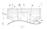
図2に、展開且つ伸長状態のおむつ1を示す。おむつ1の「展開且つ伸長状態」とは、腹側部A及び背側部Bそれぞれの外装体5の縦方向Xに沿う両側縁部を接合した状態から切り離して展開状態とし、その展開状態のおむつ1を各部の弾性部材を伸長させて設計寸法(弾性部材の影響を一切排除した状態で平面状に拡げたときの寸法と同じ)となるまで拡げた状態をいう。 FIG. 2 shows thediaper 1 in an unfolded and stretched state. The “unfolded and stretched state” of thediaper 1 refers to a state in which both side edges of theouter body 5 of the abdominal portion A and the back portion B along the longitudinal direction X are separated from the joined state to be in a developed state, and thediaper 1 in the spread state is expanded to the design dimensions (same as the dimensions when expanded in a plane state in which the influence of the elastic members is completely eliminated) by stretching the elastic members of each part.

おむつ1は、腹側部Aから股下部Cを介して背側部Bに延びる方向に対応する縦方向Xと、該おむつ1を図2に示すように平面状に拡げた状態において、該縦方向Xと直交する横方向Yとを有している。縦方向Xは、吸収性本体4の長手方向と一致している。おむつ1は、図2に示すように、縦方向Xに延びる、該おむつ1を横方向Yに2等分する縦方向中心線CLに対して左右対称に形成されている。
おむつ1における吸収性本体4は、肌対向面側に表面シート2と、非肌対向面側に裏面シート3とを有し、これら両シート2,3間に吸収体40を有している。吸収体40は、表面シート2、裏面シート3及び吸収体40は、少なくとも股下部Cの全域に位置するとともに、股下部Cから縦方向Xに沿って腹側部A及び背側部Bの少なくとも一部にまで亘って延在している。おむつ1において吸収体40は、液保持性の吸収性コア41と該吸収性コア41を被覆するコアラップシート42とを含んで構成されているが、吸収体40はコアラップシートを含んでいなくともよい。
Thediaper 1 has a longitudinal direction X corresponding to the direction extending from the abdominal part A to the dorsal part B via the crotch part C, and a lateral direction Y perpendicular to the longitudinal direction X when thediaper 1 is flattened as shown in FIG. The longitudinal direction X coincides with the longitudinal direction of the absorbentmain body 4 . As shown in FIG. 2, thediaper 1 is formed symmetrically with respect to a longitudinal center line CL extending in the longitudinal direction X and bisecting thediaper 1 in the lateral direction Y. As shown in FIG.
Theabsorbent body 4 of thediaper 1 has a topsheet 2 on the skin-facing side and a backsheet 3 on the non-skin-facing side, and anabsorbent body 40 between these sheets 2 and 3 . Theabsorbent body 40 includes the top sheet 2, the back sheet 3, and theabsorbent body 40. Theabsorbent body 40 is positioned over at least the entire crotch part C, and extends from the crotch part C along the longitudinal direction X to at least a part of the ventral part A and the dorsal part B. In thediaper 1, theabsorbent body 40 includes a liquid-retentiveabsorbent core 41 and acore wrap sheet 42 covering theabsorbent core 41, but theabsorbent body 40 may not include a core wrap sheet.

おむつ1は、図2に示すように、縦方向Xに沿う吸収性本体4の両側部それぞれに、該縦方向Xに沿って延びる防漏カフ6,6を備えている。防漏カフ6,6は、吸収性本体4の縦方向Xの全長に亘って連続する撥水性のカフ形成用シート61と、カフ形成用シート61の横方向Yの内方側に縦方向Xに伸長状態で固定された1本又は複数本のカフ弾性部材62とを含んで構成されている。防漏カフ6,6は、縦方向Xに延びるカフ固定部(不図示)を介して表面シートに固定されている。防漏カフ6,6は、カフ弾性部材62を有することで、肌対向面側に起立する。 As shown in FIG. 2, thediaper 1 has leak-proof cuffs 6, 6 extending in the longitudinal direction X on both sides of theabsorbent body 4 in the longitudinal direction X, respectively. The leak-proof cuffs 6, 6 include a water-repellent cuff-formingsheet 61 continuous over the entire length of theabsorbent body 4 in the longitudinal direction X, and one or more cuffelastic members 62 fixed to the inner side of the cuff-formingsheet 61 in the lateral direction Y in a state of being stretched in the longitudinal direction X. The leak-preventingcuffs 6, 6 are fixed to the top sheet via cuff fixing portions (not shown) extending in the longitudinal direction X. As shown in FIG. The leak-proof cuffs 6, 6 have the cuffelastic member 62 so that they stand up on the side facing the skin.

外装体5、吸収性本体4に含まれる表面シート2、裏面シート3及び吸収体40、並びに防漏カフ6,6等の構成部材に用いられる材料としては、当該技術分野においてこれまで用いられてきたものと同様のものを特に制限なく用いることができる。 As materials used for constituent members such as theexterior body 5, the top sheet 2, the back sheet 3, theabsorbent body 40, and theleakage prevention cuffs 6, 6 included in theabsorbent body 4, the same materials that have been used so far in the relevant technical field can be used without particular limitation.

本実施形態のおむつ1は、該おむつの外面である外装体5に廃棄用テープが設けられている。具体的には、図1に示すように、背側部Bにおける外装体5に廃棄用テープ10が設けられている。廃棄用テープ10は、おむつ1の廃棄形態を維持するために用いられるものである。廃棄用テープ10は、おむつ1の背側部Bにおける横方向Yの略中央部に位置している。また本実施形態の廃棄用テープ10は、その長手方向がおむつ1の縦方向Xに一致するように設けられている。 Thediaper 1 of this embodiment is provided with a disposal tape on theexterior body 5, which is the outer surface of the diaper. Specifically, as shown in FIG. 1, adisposal tape 10 is provided on theexterior body 5 in the dorsal portion B. As shown in FIG. Thedisposal tape 10 is used to maintain the disposal form of thediaper 1 . Thedisposal tape 10 is positioned substantially in the center in the lateral direction Y of the dorsal portion B of thediaper 1 . Further, thedisposal tape 10 of this embodiment is provided so that its longitudinal direction coincides with the longitudinal direction X of thediaper 1 .

図3には、廃棄するときのおむつ1の廃棄形態が示されている。おむつ1を廃棄するときには、図1に示すおむつ1において腹側部Aが内向きになるように、おむつ1を股下部Cからウエスト開口部1Wに向けて巻き上げていき、図3に示す巻き上げ形態を作る。巻き上げ形態のおむつ1では、背側部Bに設けられている廃棄用テープ10が、巻き上げたおむつ1の外側に露出している。廃棄用テープ10は、後述するように該テープ10の長手方向に伸長された後、巻き上げられて廃棄形態となったおむつ1の外周に巻き付けられ、おむつ1を廃棄形態に維持する。 FIG. 3 shows how thediaper 1 is discarded. When discarding thediaper 1, thediaper 1 shown in FIG. 1 is rolled up from the crotch part C toward the waist opening 1W so that the abdominal part A of thediaper 1 is directed inward, thereby forming the rolled-up form shown in FIG. In the rolled-updiaper 1 , thedisposal tape 10 provided on the back portion B is exposed to the outside of the rolled-updiaper 1 . As will be described later, thedisposal tape 10 is stretched in the longitudinal direction of thetape 10, and then wound around the outer periphery of thediaper 1 that has been rolled up and put into the disposal form, thereby maintaining thediaper 1 in the disposal form.

図4には、三つ折り状態になっている廃棄用テープ10の断面構造が示されている。廃棄用テープ10は、主として3つの部位から構成されている。具体的には、廃棄用テープ10は、固定部12と、中間部15と、止着部18とから構成されている。これら固定部12、中間部15、及び止着部18は、この順で廃棄用テープ10の長手方向X1に沿って配置されている。また本実施形態の廃棄用テープ10は、固定部12、中間部15、及び止着部18の順で積層された三つ折り状態になっている。固定部12と中間部15との間には他の部材は介在しておらず、両者は直接に連設されている。同様に、中間部15と止着部18との間にも他の部材は介在しておらず、両者は直接に連設されている。 FIG. 4 shows the cross-sectional structure of thedisposal tape 10 folded in three. Thedisposal tape 10 is mainly composed of three parts. Specifically, thedisposal tape 10 is composed of a fixingportion 12 , anintermediate portion 15 and a fixingportion 18 . The fixedportion 12, theintermediate portion 15, and thefastening portion 18 are arranged in this order along the longitudinal direction X1 of thedisposal tape 10. As shown in FIG. Further, thedisposal tape 10 of this embodiment is in a three-fold state in which the fixedportion 12, theintermediate portion 15, and thefastening portion 18 are laminated in this order. No other member is interposed between the fixedportion 12 and theintermediate portion 15, and the two are directly connected. Similarly, no other member is interposed between theintermediate portion 15 and thefastening portion 18, and both are directly connected.

廃棄用テープ10における固定部12は、固定部用シート片13を有している。固定部用シート片13は、第1面13a及び第2面13bを有している。三つ折り状態になっている廃棄用テープ10において固定部用シート片13は、後述する折り返し部13’を除いて、第1面13aが中間部15と対向し、第2面13bがおむつ1の外面と対向している。また固定部12は固定部用粘着部14を有している。固定部用粘着部14は、固定部用シート片13の第2面13bに設けられている。固定部12は、固定部用粘着部14によって、おむつ1における背側部Bの外面に固定されている。この固定部用粘着部14を介して、廃棄用テープ10は、おむつ1における背側部Bの外面に着脱不能に固定されている。廃棄用テープ10をおむつ1の外面に固定する方法としては、ホットメルト型接着剤等の接着剤、融着等の公知の方法を用いることができる。 The fixingportion 12 of thedisposal tape 10 has a fixingportion sheet piece 13 . The fixingportion sheet piece 13 has afirst surface 13a and asecond surface 13b. In thedisposal tape 10 folded in three, the fixingportion sheet piece 13 has afirst surface 13a facing theintermediate portion 15 and asecond surface 13b facing the outer surface of thediaper 1, except for a foldedportion 13' described later. The fixingportion 12 also has anadhesive portion 14 for fixing portion. The fixing portionadhesive portion 14 is provided on thesecond surface 13 b of the fixingportion sheet piece 13 . The fixingpart 12 is fixed to the outer surface of the dorsal part B of thediaper 1 by theadhesive part 14 for fixing part. Thedisposal tape 10 is non-detachably fixed to the outer surface of the dorsal portion B of thediaper 1 via the fixing portionadhesive portion 14 . As a method for fixing thedisposal tape 10 to the outer surface of thediaper 1, a known method such as an adhesive such as a hot-melt adhesive or fusion bonding can be used.

中間部15は中間部用シート片16を有している。中間部用シート片16は、先に述べた固定部用シート片13と同じ長さであってもよく、異なる長さであってもよい。また、中間部用シート片16は、固定部用シート片13と同じ幅であってもよく、異なる幅であってもよい。中間部用シート片16は、第1面16a及び第2面16bを有している。三つ折り状態になっている廃棄用テープ10において中間部用シート片16は、後述する折り返し部16’を除いて、第1面16aが止着部18と対向し、第2面16bが固定部12と対向している。また中間部15は中間部用粘着部17を有している。中間部用粘着部17は、中間部用シート片16の第2面16bに設けられている。中間部用粘着部17は、三つ折り状態になっている廃棄用テープ10における中間部15と固定部12との間を剥離可能に接合するものである。したがって中間部用粘着部17は、低粘着性の粘着剤から構成されていることが好ましい。 Theintermediate portion 15 has an intermediateportion sheet piece 16 . The intermediateportion sheet piece 16 may have the same length as the fixedportion sheet piece 13 described above, or may have a different length. Further, thesheet piece 16 for the intermediate portion may have the same width as thesheet piece 13 for the fixed portion, or may have a different width. Theintermediate sheet piece 16 has afirst surface 16a and asecond surface 16b. In thedisposal tape 10 folded in three, thefirst surface 16a of theintermediate sheet piece 16 faces thefastening portion 18, and thesecond surface 16b faces the fixedportion 12, except for the folded portion 16' described later. Further, theintermediate portion 15 has anadhesive portion 17 for intermediate portion. The intermediateadhesive portion 17 is provided on thesecond surface 16 b of theintermediate sheet piece 16 . The adhesive portion forintermediate portion 17 is for detachably joining between theintermediate portion 15 and the fixedportion 12 of thedisposal tape 10 folded in three. Therefore, it is preferable that theadhesive portion 17 for the intermediate portion is made of a low-adhesive adhesive.

先に述べた固定部12は、固定部用シート片13は、廃棄用テープ10の長手方向X1における一端が中間部15側に折り返された折り返し部13’を有している。そして折り返し部13’が、中間部15における中間部用シート片16の一端と第2面16bの側で接合されている。これによって、固定部12と中間部15とは直接に連設されている。固定部12と中間部15とを連設する方法としては、ホットメルト型接着剤等の接着剤、融着等の公知の方法を用いることができる。 In the fixingportion 12 described above, the fixingportion sheet piece 13 has a foldedportion 13 ′ in which one end of thedisposal tape 10 in the longitudinal direction X<b>1 is folded back toward theintermediate portion 15 . The foldedportion 13' is joined to one end of the intermediateportion sheet piece 16 in theintermediate portion 15 on thesecond surface 16b side. As a result, the fixedportion 12 and theintermediate portion 15 are directly connected. As a method for connecting the fixingportion 12 and theintermediate portion 15, a known method such as an adhesive such as a hot-melt adhesive or fusion bonding can be used.

廃棄用テープ10における止着部18は、おむつ1の外面における任意の位置に止着可能になっており、おむつ1の廃棄形態を廃棄用テープ10で維持するときに、おむつ1の外面に止着される部位である。止着部18は廃棄用テープ10の先端域を形成しており、止着部用シート片19を有している。止着部用シート片19は、固定部用シート片13又は中間部用シート片16と同じ長さであってもよく、異なる長さであってもよい。また、止着部用シート片19は、固定部用シート片13又は中間部用シート片16と同じ幅であってもよく、異なる幅であってもよい。止着部用シート片19は、第1面19a及び第2面19bを有している。本実施形態の三つ折り状態になっている廃棄用テープ10において止着部用シート片19は、第2面19bが中間部15と対向している。また止着部18は止着部用粘着部20を有している。止着部用粘着部20は、止着部用シート片19の第2面19bに設けられている。止着部用粘着部20は、三つ折り状態になっている廃棄用テープ10における止着部18と中間部15との間を剥離可能に接合し、且つ止着部18をおむつ1の外面における任意の位置に確実に止着するものである。この観点から止着部用粘着部20の粘着性の程度が決定されることが好ましい。 Thefastening portion 18 of thedisposal tape 10 can be attached at any position on the outer surface of thediaper 1, and is a portion attached to the outer surface of thediaper 1 when the disposal form of thediaper 1 is maintained by thedisposal tape 10. Thefastening portion 18 forms the tip region of thedisposal tape 10 and has a fasteningportion sheet piece 19 . The fasteningportion sheet piece 19 may have the same length as the fixedportion sheet piece 13 or the intermediateportion sheet piece 16, or may have a different length. Further, the fasteningportion sheet piece 19 may have the same width as the fixedportion sheet piece 13 or the intermediateportion sheet piece 16, or may have a different width. The fasteningportion sheet piece 19 has afirst surface 19a and asecond surface 19b. In thedisposal tape 10 folded in three according to the present embodiment, thesecond surface 19 b of the fasteningportion sheet piece 19 faces theintermediate portion 15 . Further, thefastening portion 18 has a fastening portionadhesive portion 20 . The fastening portionadhesive portion 20 is provided on thesecond surface 19 b of the fasteningportion sheet piece 19 . Theadhesive portion 20 for the fastening portion detachably joins thefastening portion 18 and theintermediate portion 15 of thedisposal tape 10 folded in three, and securely attaches thefastening portion 18 to an arbitrary position on the outer surface of thediaper 1. From this point of view, it is preferable to determine the degree of adhesiveness of theadhesive portion 20 for the fastening portion.

先に述べた中間部15における中間部用シート片16は、その長手方向X1における一端が止着部18側に折り返された折り返し部16’が形成されている。そして折り返し部16’が、止着部18における止着部用シート片19の一端と第2面19bの側で接合されている。これによって、中間部15と止着部18とは直接に連設されている。中間部15と止着部18とを連設する方法としては、ホットメルト型接着剤等の接着剤、融着等の公知の方法を用いることができる。
また、止着部18における止着部用シート片19の他端には、第2面19b側に摘まみ片21が接合されている。摘まみ片21は、止着部用シート片19とは別体のシート片である。
The intermediateportion sheet piece 16 in theintermediate portion 15 described above has a foldedportion 16 ′ formed by folding back one end in the longitudinal direction X1 toward thefastening portion 18 side. The folded portion 16' is joined to one end of the fasteningportion sheet piece 19 of thefastening portion 18 on thesecond surface 19b side. As a result, theintermediate portion 15 and thefastening portion 18 are directly connected. As a method for continuously providing theintermediate portion 15 and thefastening portion 18, a known method such as an adhesive such as a hot-melt adhesive or fusing can be used.
Aknob piece 21 is joined to the other end of the fasteningportion sheet piece 19 in thefastening portion 18 on thesecond surface 19b side. The grippingpiece 21 is a sheet piece separate from the fasteningportion sheet piece 19 .

本実施形態における固定部12、中間部15、及び止着部18の3つの部位から構成される廃棄用テープ10は、Z字状に三つ折りされている。この三つ折り状態になっている廃棄用テープ10における自由端、すなわち止着部18における摘まみ片21の取付け部位が、おむつ1におけるウエスト開口部1W側を向くように、廃棄用テープ10はおむつ1の背側部Bに取り付けられている。 Thedisposal tape 10, which is composed of three portions, the fixedportion 12, theintermediate portion 15, and thefastening portion 18, in this embodiment, is folded in three in a Z shape. Thedisposal tape 10 is attached to the back side portion B of thediaper 1 so that the free end of thedisposal tape 10 folded in three, i.e., the attachment portion of thegripping piece 21 in thefastening portion 18, faces thewaist opening 1W side of thediaper 1.

廃棄用テープ10における中間部15及び止着部18は、該廃棄用テープ10の長手方向X1に伸長可能である。例えば、廃棄用テープ10に引張力が加わったときに中間部15及び止着部18それぞれが伸長して、廃棄用テープ10の長さを増加させる。本実施形態において中間部15及び止着部18は、三つ折り状態を解除した展開状態において廃棄用テープ10の長手方向X1に伸長可能である。ここで、三つ折り状態を解除した展開状態とは、廃棄用テープ10の中間部15と固定部12との間を剥離し、且つ中間部15と止着部18との間を剥離して、三つ折り状態の廃棄用テープ10を直線状に展開した状態を意味する。前記展開状態において、廃棄用テープ10は、人の力によって引き伸ばすことができ、その際、中間部15及び止着部18を伸長させることができる。 Theintermediate portion 15 and thefastening portion 18 of thedisposal tape 10 can be extended in the longitudinal direction X1 of thedisposal tape 10 . For example, when a tensile force is applied to thedisposal tape 10 , each of theintermediate portion 15 and thefastening portion 18 expands to increase the length of thedisposal tape 10 . In the present embodiment, theintermediate portion 15 and thefastening portion 18 can extend in the longitudinal direction X1 of thedisposal tape 10 in the unfolded state after releasing the three-fold state. Here, the unfolded state in which the three-folded state is released means a state in which theintermediate portion 15 and the fixedportion 12 of thedisposal tape 10 are separated, and theintermediate portion 15 and the fixingportion 18 are separated, and the three-foldeddisposal tape 10 is unfolded linearly. In the unfolded state, thedisposal tape 10 can be stretched by human force, and at that time, theintermediate portion 15 and thefastening portion 18 can be stretched.

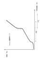
本実施形態の中間部15は、廃棄用テープ10に引張強度が加わったときに比較的弱い引張強度で容易に伸長し、止着部18は、比較的強い引張強度で伸長する。斯かる中間部15及び止着部18それぞれの伸長と引張強度との関係について詳述する。図5には、中間部15及び止着部18それぞれについて、引張強度に伴って変化する伸度を表す、引張強度と伸度との関係曲線のグラフが示されている。図5に示すグラフでは、引張強度をX軸とし、伸度をY軸としている。斯かる関係曲線を、「引張強度-伸度の関係曲線」ともいう。「伸度」は、伸長前の自然長に対する伸長後の長さの割合(%)である。例えば伸度100%は、自然長に対して2倍の長さに伸長したことを表す。 Theintermediate portion 15 of the present embodiment is easily stretched with relatively weak tensile strength when tensile strength is applied to thedisposal tape 10, and thefastening portion 18 is stretched with relatively strong tensile strength. The relationship between the elongation and tensile strength of each of theintermediate portion 15 and thefastening portion 18 will be described in detail. FIG. 5 shows a graph of a relationship curve between tensile strength and elongation, which represents elongation that changes with tensile strength, for each of theintermediate portion 15 and thefastening portion 18 . In the graph shown in FIG. 5, the tensile strength is on the X-axis and the elongation is on the Y-axis. Such a relationship curve is also referred to as a “tensile strength-elongation relationship curve”. "Elongation" is the ratio (%) of the length after stretching to the natural length before stretching. For example, an elongation of 100% means that the stretched length is double the natural length.

本実施形態の中間部15及び止着部18それぞれの引張強度-伸度の関係曲線は、引張強度の増加に応じた伸度の変化をみたとき、伸度の変化量が少ない低伸長段階と、該低伸長段階から変曲点を経て、伸度が急激に増大する高伸長段階とを有する。図5では、中間部15の引張強度-伸度の関係曲線における、低伸長段階をFb1、高伸長段階をFb2で示し、止着部18の引張強度-伸度の関係曲線における、低伸長段階をFc1、高伸長段階をFc2で示す。また、中間部15の引張強度-伸度の関係曲線の変曲点E1における引張強度を第1変曲引張強度P1、止着部18の引張強度-伸度の関係曲線の変曲点E2における引張強度を第2変曲引張強度P2という。更に、引張強度-伸度の関係曲線における引張強度の最大値を、中間部15又は止着部18が破断する引張強度(以下、破断強度という)とする。 The tensile strength-elongation relationship curve of each of theintermediate portion 15 and thefastening portion 18 of the present embodiment has a low elongation stage in which the amount of change in elongation is small when the change in elongation according to an increase in tensile strength is observed, and a high elongation stage in which the elongation rapidly increases from the low elongation stage through an inflection point. In FIG. 5, in the tensile strength-elongation relationship curve of theintermediate portion 15, the low elongation stage is indicated by Fb1 and the high elongation stage is indicated by Fb2, and the tensile strength-elongation relationship curve of thefastening portion 18 is indicated by Fc1 and Fc2. The tensile strength at the inflection point E1 of the tensile strength-elongation relationship curve of theintermediate portion 15 is referred to as the first inflection tensile strength P1, and the tensile strength at the inflection point E2 of the tensile strength-elongation relationship curve of thefastening portion 18 is referred to as the second inflection tensile strength P2. Further, the maximum value of the tensile strength in the tensile strength-elongation relationship curve is defined as the tensile strength at which theintermediate portion 15 or thefastening portion 18 breaks (hereinafter referred to as breaking strength).

中間部15及び止着部18それぞれの引張強度-伸度の関係曲線に関し、少なくとも止着部18の引張強度-伸度の関係曲線が、前記低伸長段階と、前記高伸長段階とを有していればよい。中間部15は、その引張強度-伸度の関係曲線において、変曲点E1が明確に現れなくてもよい。例えば、中間部15が、その引張強度-伸度の関係曲線における原点から破断強度に至るまで、引張強度の増加に応じて伸度が暫時増加する場合も本発明に含まれる。斯かる場合、中間部15の引張強度-伸度の関係曲線は、低伸長段階Fb1を有さず、当該関係曲線の原点から破断強度に至るまでの段階を高伸長段階Fb2として有するものとする。即ち、斯かる中間部15の引張強度-伸度の関係曲線は、高伸長段階Fb2のみを有する。 Regarding the tensile strength-elongation relationship curves of theintermediate portion 15 and thefastening portion 18, at least the tensile strength-elongation relationship curve of thefastening portion 18 should have the low elongation stage and the high elongation stage. In theintermediate portion 15, the inflection point E1 does not have to appear clearly in the tensile strength-elongation relationship curve. For example, the present invention also includes the case where theintermediate portion 15 gradually increases in elongation as the tensile strength increases from the origin of the tensile strength-elongation relationship curve to the breaking strength. In such a case, the tensile strength-elongation relationship curve of theintermediate portion 15 does not have a low elongation stage Fb1, and has a high elongation stage Fb2 from the origin of the relationship curve to the breaking strength. That is, the tensile strength-elongation relationship curve of theintermediate portion 15 has only the high elongation stage Fb2.

図5に示すように、中間部15の引張強度-伸度の関係曲線と、止着部18の引張強度-伸度の関係曲線とを比較したとき、止着部18の低伸長段階Fc1に対応する引張強度の範囲においては、中間部15の伸度が止着部18の伸度よりも大きい。即ち、中間部15及び止着部18の各引張強度-伸度の関係曲線を比較したとき、原点から第2変曲引張強度P2までの範囲においては、中間部15の伸度が止着部18の伸度よりも大きい。本実施形態における中間部15の引張強度-伸度の関係曲線では、第2変曲引張強度P2よりも低い引張強度で第1変曲点E1が現れており、中間部15の高伸長段階Fb2と、止着部18の低伸長段階Fc1とが部分的に重複している。本実施形態の第1変曲点E1は、止着部18の低伸長段階Fc1に対応する引張強度の範囲で現れ、第2変曲点E2は、中間部15の高伸長段階Fb2に対応する引張強度の範囲で現れる。また、図5に示すように、中間部15の破断強度Peは、第2変曲引張強度P2よりも大きい。中間部15の破断強度Peは、止着部18の高伸長段階Fc2に対応する引張強度の範囲で現れる。したがって、本実施形態における中間部15及び止着部18それぞれの引張強度-伸度の関係曲線は、以下の関係式(1)を満たす。
P1<P2<Pe ・・・(1)
P1は第1変曲引張強度であり、P2は第2変曲引張強度であり、Peは中間部15の破断強度である。
As shown in FIG. 5, when the tensile strength-elongation relationship curve of theintermediate portion 15 and the tensile strength-elongation relationship curve of thefastening portion 18 are compared, the tensile strength of thefastening portion 18 corresponds to the low extension stage Fc1. That is, when the tensile strength-elongation relationship curves of theintermediate portion 15 and thefastening portion 18 are compared, the elongation of theintermediate portion 15 is greater than the elongation of thefastening portion 18 in the range from the origin to the second inflection tensile strength P2. In the tensile strength-elongation relationship curve of theintermediate portion 15 in this embodiment, the first inflection point E1 appears at a tensile strength lower than the second inflection tensile strength P2, and the high elongation stage Fb2 of theintermediate portion 15 and the low elongation stage Fc1 of thefastening portion 18 partially overlap. The first inflection point E1 of the present embodiment appears in the tensile strength range corresponding to the low elongation stage Fc1 of thefastening portion 18, and the second inflection point E2 appears in the tensile strength range corresponding to the high elongation stage Fb2 of theintermediate portion 15. Moreover, as shown in FIG. 5, the breaking strength Pe of theintermediate portion 15 is greater than the second inflexion tensile strength P2. The breaking strength Pe of theintermediate portion 15 appears in a tensile strength range corresponding to the high elongation stage Fc2 of thefastening portion 18 . Therefore, the tensile strength-elongation relationship curves of theintermediate portion 15 and thefastening portion 18 in this embodiment satisfy the following relational expression (1).
P1<P2<Pe (1)
P1 is the first inflection tensile strength, P2 is the second inflection tensile strength, and Pe is the breaking strength of theintermediate portion 15 .

本実施形態の廃棄用テープ10は、止着部18を指等で把持して、廃棄用テープ10の長手方向X1に引き伸ばすことにより、中間部15及び止着部18それぞれを伸長させることができる。図6には、廃棄用テープ10を引き伸ばしたときの引張強度と伸度との関係曲線が、中間部15の高伸長段階Fb2及び止着部18の高伸長段階Fc2それぞれに対応する引張強度の範囲とともに示されている。廃棄用テープ10を引き伸ばす過程において、中間部15に加えられる引張強度が第1変曲引張強度P1(図6において不図示)に至ると、中間部15の高伸長段階Fb2となって、中間部15の伸度が急激に増加する。この廃棄用テープ10を引き伸ばし続けると、中間部15は伸長し続ける。そして止着部18に加えられる引張強度が第2変曲引張強度P2(図6において不図示)に至ると、止着部18の高伸長段階Fc2となって、止着部18の伸度が急激に増加する。第2変曲引張強度P2以降、中間部15は破断強度Peに達するまで伸長し続ける。即ち、廃棄用テープ10の伸長過程において、止着部18の低伸長段階Fc1に対応する引張強度の範囲では、中間部15が主に伸長する。そして、止着部18の高伸長段階Fc2に対応する引張強度の範囲では、止着部18が主に伸長する。換言すると、先ず中間部15が伸長し始め、中間部15がある程度伸長すると、止着部18が伸長し始め、中間部15とともに伸長し続ける(図6参照)。斯かる廃棄用テープ10は、その引張強度-伸度の関係曲線が、伸度が急激に増大する段階を二段階有しているので、該廃棄用テープ10を伸長させたとき二段階で伸長する。 Theintermediate portion 15 and thefastening portion 18 of thedisposal tape 10 of the present embodiment can be stretched by gripping thefastening portion 18 with fingers or the like and stretching thedisposal tape 10 in the longitudinal direction X1. FIG. 6 shows the relationship curve between the tensile strength and the elongation when thetape 10 for disposal is stretched, along with the range of tensile strength corresponding to the high elongation stage Fb2 of theintermediate portion 15 and the high elongation stage Fc2 of thefastening portion 18. In the process of stretching thedisposal tape 10, when the tensile strength applied to theintermediate portion 15 reaches the first inflection tensile strength P1 (not shown in FIG. 6), theintermediate portion 15 reaches a high elongation stage Fb2, and the elongation of theintermediate portion 15 sharply increases. As thedisposal tape 10 continues to be stretched, theintermediate portion 15 continues to stretch. When the tensile strength applied to thefastening portion 18 reaches the second inflectional tensile strength P2 (not shown in FIG. 6), thefastening portion 18 reaches a high elongation stage Fc2, and the elongation of thefastening portion 18 increases sharply. After the second inflection tensile strength P2, theintermediate portion 15 continues to elongate until it reaches the breaking strength Pe. That is, in the process of elongating thedisposal tape 10, theintermediate portion 15 is mainly elongated within the tensile strength range corresponding to the low elongation stage Fc1 of thefastening portion 18. As shown in FIG. In the tensile strength range corresponding to the high elongation stage Fc2 of thefastening portion 18, thefastening portion 18 mainly extends. In other words, theintermediate portion 15 begins to stretch first, and when theintermediate portion 15 stretches to some extent, thefastening portion 18 begins to stretch and continues to stretch together with the intermediate portion 15 (see FIG. 6). Thedisposal tape 10 has a tensile strength-elongation relationship curve having two stages in which the elongation increases sharply.

幼児の保護者や介護者等のおむつ1を廃棄形態にする作業者は、廃棄用テープ10を伸長させるとき、上述した中間部15及び止着部18の各伸度の変化によって、廃棄用テープ10が2段階で伸長することを感覚的に知覚し得る。これにより、例えば、止着部18が伸長を開始した場合、即ち廃棄用テープ10に二段階目の伸長が起きた場合にはそれ以上伸長させるべきではないことを情報として与えておくことで、作業者が中間部15を過度に伸長させることを防止でき、該中間部15が破断することを防止することができる。この「それ以上伸長させるべきではないことを情報として与えておく」ことについての「情報」とは、例えば「摘んでいる部分が伸び始めたらそれ以上伸ばさないでください」との文章であり、文章でも記号でもそれらの組み合わせ等であっても良く、そのような情報は、例えば、おむつの構成部材やおむつのパッケージ、おむつに関する広告やホームページに表示する。また作業者は、中間部15を過度に伸長させることなく、廃棄用テープ10を十分に引き伸ばすことができる。廃棄用テープ10を十分に伸長させると、巻き上げたおむつに該廃棄用テープを容易に巻き付けることができる。即ち、本実施形態の廃棄用テープは、破断を効果的に防止しつつ、十分に伸長させられるので、おむつ1を廃棄形態にする作業性に優れる。 A worker, such as a parent or caregiver of an infant, who disposes thediaper 1 in the form of disposal, when stretching thedisposal tape 10, can intuitively perceive that thedisposal tape 10 is stretched in two steps due to the change in the elongation of theintermediate portion 15 and thefastening portion 18 described above. As a result, for example, when thefastening portion 18 starts to stretch, i.e., when thetape 10 for disposal is stretched in the second stage, it is possible to prevent the operator from overstretching theintermediate portion 15 and to prevent theintermediate portion 15 from breaking by providing information that the tape should not be stretched any further. The ``information'' about this ``giving information that it should not be stretched any further'' is, for example, a sentence that ``do not stretch any more when the picked part begins to stretch'', and it may be a sentence, a symbol, or a combination of them. Also, the operator can sufficiently stretch thedisposal tape 10 without excessively stretching theintermediate portion 15 . When thedisposal tape 10 is stretched sufficiently, it can be easily wrapped around the rolled-up diaper. That is, the disposal tape of the present embodiment can be sufficiently stretched while effectively preventing breakage, so that it is excellent in workability to put thediaper 1 into the disposal form.

中間部15及び止着部18それぞれの引張強度-伸度の関係曲線は、以下の方法により得られる。
〔引張強度-伸度の関係曲線の取得方法〕
廃棄用テープの長手方向を引張方向に一致させ、中間部15又は止着部18の各部位を引張試験機(例えば株式会社 島津製作所社製、機種「AUTOGRAPH AG-X」)のチャックに取り付ける。廃棄用テープが、三つ折り状態等、折り畳まれた状態の場合は、その折り畳まれた状態を解除した展開状態にしてから、チャックに取り付ける。中間部15又は止着部18を取り付ける際、隣接する他の部位との接合箇所を避けて、前記チャックに取り付ける。例えば、中間部15をチャックに取り付ける場合、止着部18との接合箇所及び固定部12との接合箇所を避け、これら両接合箇所間をチャックに取り付ける。チャック間距離は10mmとする。このチャック間距離が伸長前の自然長となる。本方法において廃棄用テープの幅、即ち廃棄用テープの長手方向と直交する方向の長さは、吸収性物品に取り付けてある廃棄用テープのそのままの幅とする。次いで、取り付けた中間部15又は止着部18を300mm/minの速度で引っ張り、引張距離に伴って変化する引張強度を測定して、引張強度-伸度の関係曲線を得る。伸度は、測定を開始してからチャックが移動した距離を伸長前の自然長で除した値の百分率で求める。中間部15の引張強度-伸度の関係曲線において、引張強度0(原点)から第1変曲点E1までを低伸長段階Fb1とし、第1変曲点E1から最大引張強度までを高伸長段階Fb2とする。中間部15の引張強度-伸度の関係曲線において、第1変曲点E1が現れない場合は、引張強度0(原点)から最大引張強度までを高伸長段階Fb2とする。止着部18の引張強度-伸度の関係曲線において、引張強度0(原点)から第2変曲点E2までを低伸長段階Fc1とし、第2変曲点E2から最大引張強度までを高伸長段階Fc2とする。また、引張強度-伸度の関係曲線における引張強度の最大値を破断強度とする。得られた引張強度-伸度の関係曲線における第1変曲点E1及び第2変曲点E2それぞれは、以下の方法により求められる。
The tensile strength-elongation relationship curves of theintermediate portion 15 and thefastening portion 18 are obtained by the following method.
[Method for obtaining relationship curve of tensile strength - elongation]
The longitudinal direction of the disposal tape is aligned with the tensile direction, and each part of theintermediate portion 15 or the fixingportion 18 is attached to a chuck of a tensile tester (for example, model "AUTOGRAPH AG-X" manufactured by Shimadzu Corporation). When the disposal tape is in a folded state such as a three-fold state, it is attached to the chuck after the folded state is released and unfolded. When attaching theintermediate portion 15 or thefastening portion 18, it is attached to the chuck while avoiding joints with other adjacent portions. For example, when attaching theintermediate portion 15 to the chuck, avoid the joints with thefastening portion 18 and the joints with the fixingportion 12, and attach the chuck between these joints. The chuck-to-chuck distance is 10 mm. This chuck-to-chuck distance is the natural length before extension. In this method, the width of the disposal tape, that is, the length of the disposal tape in the direction orthogonal to the longitudinal direction is the width of the disposal tape attached to the absorbent article. Next, the attachedintermediate portion 15 orfastening portion 18 is pulled at a speed of 300 mm/min, and the tensile strength that changes with the pulling distance is measured to obtain a tensile strength-elongation relationship curve. The elongation is obtained as a percentage of a value obtained by dividing the distance traveled by the chuck after the start of measurement by the natural length before elongation. In the tensile strength-elongation relationship curve of theintermediate portion 15, the low elongation stage Fb1 is from the tensile strength 0 (origin) to the first inflection point E1, and the high elongation stage Fb2 is from the first inflection point E1 to the maximum tensile strength. If the first inflection point E1 does not appear in the tensile strength-elongation relationship curve of theintermediate portion 15, the high elongation stage Fb2 is from the tensile strength of 0 (origin) to the maximum tensile strength. In the tensile strength-elongation relationship curve of thefastening portion 18, the low elongation stage Fc1 is from the tensile strength 0 (origin) to the second inflection point E2, and the high elongation stage Fc2 is from the second inflection point E2 to the maximum tensile strength. The breaking strength is the maximum value of the tensile strength in the tensile strength-elongation relationship curve. Each of the first inflection point E1 and the second inflection point E2 in the resulting tensile strength-elongation relationship curve is obtained by the following method.

〔第1変曲点E1又は第2変曲点E2の特定方法〕
先ず、引張強度-伸度の関係曲線のX軸及びY軸の二軸を反転させる。即ち、引張強度をY軸に、伸度をX軸とする。これら二軸を反転させた反転引張強度-伸度の関係曲線において、最初に現れる引張強度の極大点である第一極大点を第1変曲点E1又は第2変曲点E2とする。また、反転引張強度-伸度の関係曲線において当該曲線が屈曲点を有するように屈曲している場合は、該屈曲点を第1変曲点E1又は第2変曲点E2とする。
[Method of specifying first inflection point E1 or second inflection point E2]
First, the X and Y axes of the tensile strength-elongation relationship curve are reversed. That is, the tensile strength is on the Y-axis and the elongation is on the X-axis. In the reversed tensile strength-elongation relationship curve in which these two axes are reversed, the first maximum point, which is the maximum point of the tensile strength that appears first, is defined as the first inflection point E1 or the second inflection point E2. In addition, when the relationship curve of reverse tensile strength-elongation is bent so as to have a bending point, the bending point is defined as the first inflection point E1 or the second inflection point E2.

廃棄用テープ10の破断をより効果的に防止する観点から、第1変曲引張強度P1は、第2変曲引張強度P2の好ましくは70%以下、より好ましくは50%以下である。廃棄用テープ10をより確実に二段階で伸長させる観点から、第1変曲引張強度P1は、第2変曲引張強度P2の好ましくは10%以上、より好ましくは20%以上である。更に、廃棄用テープ10の破断の防止、及び廃棄用テープ10を二段階で伸長させることをより両立させる観点から、第1変曲引張強度P1は、第2変曲引張強度P2の好ましくは10%以上70%以下、より好ましくは20%以上50%以下である。 From the viewpoint of more effectively preventing breakage of thedisposal tape 10, the first bending tensile strength P1 is preferably 70% or less, more preferably 50% or less of the second bending tensile strength P2. From the viewpoint of stretching thedisposal tape 10 more reliably in two stages, the first bending tensile strength P1 is preferably 10% or more, more preferably 20% or more of the second bending tensile strength P2. Furthermore, from the viewpoint of achieving both prevention of breakage of thedisposal tape 10 and elongation of thedisposal tape 10 in two stages, the first bending tensile strength P1 is preferably 10% or more and 70% or less, more preferably 20% or more and 50% or less of the second bending tensile strength P2.

廃棄用テープ10を伸長し易くし、且つ意図せず伸長することを防止する観点から、第1変曲引張強度P1は、好ましくは1N以上、より好ましくは3N以上であり、また好ましくは10N以下、より好ましくは7N以下であり、また好ましくは1N以上10N以下、より好ましくは3N以上7N以下である。
前記関係式(1)をより確実に満たす観点から、第2変曲引張強度P2は、好ましくは10N以上、より好ましくは12N以上であり、また好ましくは19.5N以下、より好ましくは15N以下であり、また好ましくは10N以上19.5N以下、より好ましくは12N以上15N以下である。
From the viewpoint of facilitating elongation of thedisposal tape 10 and preventing unintentional elongation, the first bending tensile strength P1 is preferably 1 N or more, more preferably 3 N or more, and preferably 10 N or more, more preferably 7 N or less, and preferably 1 N or more and 10 N or less, more preferably 3 N or more and 7 N or less.
From the viewpoint of more reliably satisfying the relational expression (1), the second inflection tensile strength P2 is preferably 10 N or more, more preferably 12 N or more, and preferably 19.5 N or more, more preferably 15 N or less, and preferably 10 N or more and 19.5 N or less, more preferably 12 N or more and 15 N or less.

廃棄用テープ10が二段階に伸長することを作業者により知覚させる観点から、中間部15は、第1変曲引張強度P1における伸度が、好ましくは0%以上、より好ましくは10%以上であり、また好ましくは100%以下、より好ましくは50%以下であり、また好ましくは0%以上100%以下、より好ましくは10%以上50%以下である。
上記と同様の観点から、止着部18は、第2変曲引張強度P2における伸度が、好ましくは2%以上、より好ましくは5%以上であり、また好ましくは30%以下、より好ましくは20%以下であり、また好ましくは2%以上30%以下、より好ましくは5%以上20%以下である。
From the viewpoint of allowing the operator to perceive that thedisposal tape 10 stretches in two stages, theintermediate portion 15 preferably has an elongation of 0% or more, more preferably 10% or more, more preferably 100% or less, more preferably 50% or less, and more preferably 0% or more and 100% or less, more preferably 10% or more and 50% or less.
From the same viewpoint as above, thefastening portion 18 has an elongation at the second inflection tensile strength P2 of preferably 2% or more, more preferably 5% or more, more preferably 30% or less, more preferably 20% or less, and preferably 2% or more and 30% or less, more preferably 5% or more and 20% or less.

廃棄用テープ10の破断をより効果的に防止する観点から、止着部18は、高伸長段階Fc2における伸度の変化量が、低伸長段階Fc1における伸度の変化量に比して大きいことが好ましい。斯かる構成により、中間部15の伸長に限界が近いことを作業者により容易に知覚させることができる。前記の構成をより確実に具備する観点から、第2変曲引張強度P2に対して90%の引張強度における止着部18の伸度をS90、及び第2変曲引張強度P2に対して110%の引張強度における止着部18の伸度をS110としたとき(図5参照)、S110及びS90それぞれは以下の範囲内であることが好ましい。
110に対するS90の比率(S90/S110)は、好ましくは1/100以上、より好ましくは1/75以上であり、また好ましくは1/10以下、より好ましくは1/20以下であり、また好ましくは1/100以上1/10以下、より好ましくは1/75以上1/20以下である。
110は、好ましくは100%以上、より好ましくは200%以上であり、また好ましくは1000%以下、より好ましくは750%以下であり、また好ましくは100%以上1000%以下、より好ましくは200%以上750%以下である。
90は、好ましくは2%以上、より好ましくは5%以上であり、また好ましくは25%以下、より好ましくは15%以下であり、また好ましくは2%以上25%以下、より好ましくは5%以上15%以下である。
尚、前述した止着部18の反転引張強度-伸度の関係曲線、即ち、引張強度をY軸に、伸度をX軸とした関係曲線において、引張強度の第一極大点(第2変曲点E2)以降の伸度で、第一極大点の90%よりも低い引張強度が現れた場合は、第2変曲引張強度P2に対して、90%の引張強度を示す点であって、最も伸度が低い点での伸度をS90とする。
From the viewpoint of more effectively preventing breakage of thedisposal tape 10, the amount of change in elongation of thefastening portion 18 in the high elongation stage Fc2 is preferably larger than that in the low elongation stage Fc1. With such a configuration, the operator can easily perceive that the extension of theintermediate portion 15 is nearing its limit. From the viewpoint of providing the above configuration more reliably, when the elongation of thefastening portion 18 at a tensile strength of 90% with respect to the second inflection tensile strength P2 is S90 and the elongation of thefastening portion 18 at a tensile strength of 110% with respect to the second inflection tensile strength P2 is S110 (see FIG. 5), S110 and S90 are each preferably within the following ranges.
The ratio of S90 to S110 (S90 /S110 ) is preferably 1/100 or more, more preferably 1/75 or more, more preferably 1/10 or less, more preferably 1/20 or less, more preferably 1/100 or more and 1/10 or less, more preferably 1/75 or more and 1/20 or less.
S110 is preferably 100% or more, more preferably 200% or more, preferably 1000% or less, more preferably 750% or less, further preferably 100% or more and 1000% or less, more preferably 200% or more and 750% or less.
TheS90 is preferably 2% or more, more preferably 5% or more, preferably 25% or less, more preferably 15% or less, further preferably 2% or more and 25% or less, more preferably 5% or more and 15% or less.
In addition, in the relationship curve between the reverse tensile strength and the elongation of thefastening portion 18 described above, that is, the relationship curve with the tensile strength on the Y axis and the elongation on the X axis, the first maximum point of the tensile strength (second inflection point E2) When the tensile strength is lower than 90% of the first maximum point, the elongation at the point where the tensile strength is 90% with respect to the second inflection tensile strength P2 and the elongation at the point with the lowest elongation isS90 .

廃棄用テープ10が二段階に伸長することを作業者により知覚させる観点から、第2変曲引張強度P2に対して90%の引張強度における中間部15の伸度をT90としたとき、T90に対するS90の比率(S90/T90)は、好ましくは1/100以上、より好ましくは1/75以上であり、また好ましくは1/10以下、より好ましくは1/20以下であり、また好ましくは1/100以上1/10以下、より好ましくは1/75以上1/20以下である。
90は、好ましくは100%以上、より好ましくは200%以上であり、また好ましくは1000%以下、より好ましくは750%以下であり、また好ましくは100%以上1000%以下、より好ましくは200%以上750%以下である。
From the viewpoint of letting the operator perceive that thetape 10 for disposal is stretched in two stages, the ratio ofS90 toT90 (S90 /T90 ) is preferably 1/100 or more, more preferably 1/75 or more, more preferably 1/10 or less, more preferably 1/20 or less, and more preferably, when T90 is the elongation of theintermediate portion 15 at a tensile strength of 90% with respect to the second inflectional tensile strength P2. It is1/100 or more and 1/10 or less, more preferably 1/75 or more and 1/20 or less.
T90 is preferably 100% or more, more preferably 200% or more, preferably 1000% or less, more preferably 750% or less, further preferably 100% or more and 1000% or less, more preferably 200% or more and 750% or less.

上記と同様の観点から、引張強度を、第2変曲引張強度P2から該第2変曲引張強度P2の110%まで増大させた、止着部18の伸度の変化量をΔS1、及び中間部15の伸度の変化量をΔT1としたとき(図5参照)、ΔS1及びΔT1それぞれは以下の範囲内であることが好ましい。これら伸度の変化量は、第2変曲引張強度P2の110%の引張強度における伸度から、第2変曲引張強度P2における伸度を減算した値(%)ある。
ΔS1はΔT1の好ましくは2倍以上、より好ましくは3倍以上であり、また好ましくは50倍以下、より好ましくは20倍以下であり、また好ましくは2倍以上50倍以下、より好ましくは3倍以上20倍以下である。
ΔS1は、好ましくは100%以上、より好ましくは200%以上であり、また好ましくは1000%以下、より好ましくは750%以下であり、また好ましくは100%以上1000%以下、より好ましくは200%以上750%以下である。
ΔT1は、好ましくは20%以上、より好ましくは50%以上であり、また好ましくは200%以下、より好ましくは100%以下であり、また好ましくは20%以上200%以下、より好ましくは50%以上100%以下である。
From the same viewpoint as above, when the tensile strength is increased from the second inflectional tensile strength P2 to 110% of the second inflectional tensile strength P2, the amount of change in the elongation of thefastening portion 18 is ΔS1, and the amount of change in the elongation of theintermediate portion 15 is ΔT1 (see FIG. 5), ΔS1 and ΔT1 are preferably within the following ranges. These changes in elongation are values (%) obtained by subtracting the elongation at the second inflection tensile strength P2 from the elongation at a tensile strength of 110% of the second inflection tensile strength P2.
ΔS1 is preferably 2 times or more, more preferably 3 times or more, more preferably 50 times or less, more preferably 20 times or less, more preferably 2 times or more and 50 times or less, more preferably 3 times or more and 20 times or less, ΔT1.
ΔS1 is preferably 100% or more, more preferably 200% or more, preferably 1000% or less, more preferably 750% or less, more preferably 100% or more and 1000% or less, more preferably 200% or more and 750% or less.
ΔT1 is preferably 20% or more, more preferably 50% or more, preferably 200% or less, more preferably 100% or less, more preferably 20% or more and 200% or less, more preferably 50% or more and 100% or less.

以下、引張強度を、第2変曲引張強度P2に対して90%から100%まで増大させたときの、止着部18の伸度の変化量をΔS2とし、中間部15の伸度の変化量をΔT2とし、これらの合計変化量をΔU2とする。即ち、ΔU2=ΔS2+ΔT2である。また、引張強度を、第2変曲引張強度P2に対して100%から110%まで増大させたときの、止着部18の伸度の変化量をΔS1とし、中間部15の伸度の変化量をΔT1とし、これらの合計変化量をΔU1とする。即ち、ΔU1=ΔS1+ΔT1である。第2変曲引張強度を境に止着部18をより急激に伸長させて、中間部15の伸長に限界が近いことを作業者により知覚させる観点から、以下の関係式(2)を満たすことが好ましい。
ΔU1>ΔU2 ・・・(2)
Hereinafter, when the tensile strength is increased from 90% to 100% with respect to the second inflection tensile strength P2, the amount of change in the elongation of thefastening portion 18 is ΔS2, the amount of change in the elongation of theintermediate portion 15 is ΔT2, and the total amount of change is ΔU2. That is, ΔU2=ΔS2+ΔT2. Also, when the tensile strength is increased from 100% to 110% with respect to the second inflection tensile strength P2, the amount of change in the elongation of thefastening portion 18 is ΔS1, the amount of change in the elongation of theintermediate portion 15 is ΔT1, and the total amount of change is ΔU1. That is, ΔU1=ΔS1+ΔT1. It is preferable to satisfy the following relational expression (2) from the viewpoint of allowing the worker to perceive that the extension of theintermediate portion 15 is nearing its limit by extending thefastening portion 18 more rapidly after reaching the second inflection tensile strength.
ΔU1>ΔU2 (2)

上記と同様の観点から、ΔU1及びΔU2それぞれは以下の範囲内であることが好ましい。
ΔU1はΔU2の好ましくは2倍以上、より好ましくは3倍以上であり、また好ましくは20倍以下、より好ましくは10倍以下であり、また好ましくは2倍以上20倍以下、より好ましくは3倍以上10倍以下である。
ΔU1は、好ましくは100%以上、より好ましくは200%以上であり、また好ましくは1000%以下、より好ましくは750%以下であり、また好ましくは100%以上1000%以下、より好ましくは200%以上750%以下である。
ΔU2は、好ましくは20%以上、より好ましくは40%以上であり、また好ましくは200%以下、より好ましくは150%以下であり、また好ましくは20%以上200%以下、より好ましくは40%以上150%以下である。
From the same point of view as above, ΔU1 and ΔU2 are preferably within the following ranges.
ΔU1 is preferably 2 times or more, more preferably 3 times or more, more preferably 20 times or less, more preferably 10 times or less, more preferably 2 to 20 times, more preferably 3 to 10 times, ΔU2.
ΔU1 is preferably 100% or more, more preferably 200% or more, preferably 1000% or less, more preferably 750% or less, more preferably 100% or more and 1000% or less, more preferably 200% or more and 750% or less.
ΔU2 is preferably 20% or more, more preferably 40% or more, preferably 200% or less, more preferably 150% or less, further preferably 20% or more and 200% or less, more preferably 40% or more and 150% or less.

廃棄用テープ10をより十分に伸長させる観点から、廃棄用テープ10の長手方向X1における中間部15の伸長可能な長さは、好ましくは20mm以上、より好ましくは30mm以上であり、また好ましくは70mm以下、より好ましくは60mm以下であり、また好ましくは20mm以上70mm以下、より好ましくは30mm以上60mm以下である。
上記と同様の観点から、廃棄用テープ10の長手方向X1における止着部18の伸長可能な長さは、好ましくは20mm以上、より好ましくは30mm以上であり、また好ましくは70mm以下、より好ましくは60mm以下であり、また好ましくは20mm以上70mm以下、より好ましくは30mm以上60mm以下である。
「廃棄用テープ10の長手方向X1における伸長可能な長さ」とは、同方向X1に伸長可能な部分の自然長の長さであって、中間部15又は止着部18に隣接する他の部位との接合箇所を除く部分である。例えば、廃棄用テープ10の長手方向X1における中間部15の伸長可能な長さは、止着部18との接合箇所及び固定部12との接合箇所を除いた部分の長さである。また、廃棄用テープ10の長手方向X1における止着部18の伸長可能な長さは、摘まみ片21との接合箇所及び中間部15との接合箇所を除いた部分の長さである。
From the viewpoint of sufficiently extending thedisposal tape 10, the extendable length of theintermediate portion 15 in the longitudinal direction X1 of thedisposal tape 10 is preferably 20 mm or more, more preferably 30 mm or more, more preferably 70 mm or more, more preferably 60 mm or less, and more preferably 20 mm or more and 70 mm or less, more preferably 30 mm or more and 60 mm or less.
From the same point of view as above, the extendable length of thefastening portion 18 in the longitudinal direction X1 of thedisposal tape 10 is preferably 20 mm or more, more preferably 30 mm or more, more preferably 70 mm or less, more preferably 60 mm or less, and more preferably 20 mm or more and 70 mm or less, more preferably 30 mm or more and 60 mm or less.
The “stretchable length in the longitudinal direction X1 of thedisposal tape 10” is the length of the natural length of the stretchable portion in the same direction X1, which is adjacent to theintermediate portion 15 or thefastening portion 18. It is a portion excluding the joint with another portion. For example, the stretchable length of theintermediate portion 15 in the longitudinal direction X<b>1 of thedisposal tape 10 is the length of the portion excluding the joint with the fixingportion 18 and the joint with the fixingportion 12 . Further, the extendable length of thefastening portion 18 in the longitudinal direction X1 of thedisposal tape 10 is the length of the portion excluding the joining portion with the grippingpiece 21 and the joining portion with theintermediate portion 15 .

廃棄用テープ10を引き伸ばす過程において中間部15の破断をより効果的に抑制する観点から、第2変曲引張強度P2に対する、中間部15の破断強度Peの比率(Pe/P2)は、好ましくは1.2以上、より好ましくは2以上、更に好ましくは3以上であり、また好ましくは6以下、より好ましくは5以下であり、また好ましくは2以上6以下、より好ましくは3以上4以下である。
上記と同様の観点から、中間部15の破断強度Peは、好ましくは10N以上、より好ましくは15N以上であり、また好ましくは30N以下、より好ましくは25N以下であり、また好ましくは10N以上30N以下、より好ましくは15N以上25N以下である。
From the viewpoint of more effectively suppressing breakage of theintermediate portion 15 in the process of stretching thedisposal tape 10, the ratio of the breaking strength Pe of theintermediate portion 15 to the second bending tensile strength P2 (Pe/P2) is preferably 1.2 or more, more preferably 2 or more, still more preferably 3 or more, more preferably 6 or less, more preferably 5 or less, more preferably 2 or more and 6 or less, more preferably 3 or more and 4 or less.
From the same viewpoint as above, the breaking strength Pe of theintermediate portion 15 is preferably 10 N or more, more preferably 15 N or more, more preferably 30 N or less, more preferably 25 N or less, more preferably 10 N or more and 30 N or less, more preferably 15 N or more and 25 N or less.

廃棄用テープ10を引き伸ばす過程において止着部18の破断を抑制する観点から、止着部18の破断強度Pfは、好ましくは20N以上、より好ましくは25N以上であり、また好ましくは50N以下、より好ましくは45N以下であり、また好ましくは20N以上50N以下、より好ましくは25N以上45N以下である。 From the viewpoint of suppressing breakage of thefastening portion 18 in the process of stretching thedisposal tape 10, the breaking strength Pf of thefastening portion 18 is preferably 20 N or more, more preferably 25 N or more, more preferably 50 N or more, more preferably 45 N or less, more preferably 20 N or more and 50 N or less, more preferably 25 N or more and 45 N or less.

廃棄用テープを引っ張る際に、おむつ1外面からの固定部12の剥離を抑制する観点から、第2変曲引張強度P2は、おむつ1の外面と固定部12との間の剥離強度Pgよりも低いことが好ましい。上記と同様の観点から、おむつ1の外面と固定部12との間の剥離強度Pgは、以下の範囲内であることが好ましい。
第2変曲引張強度P2に対する、おむつ1の外面と固定部12との間の剥離強度Pgの比率(Pg/P2)は、好ましくは3以上、より好ましくは4以上であり、また好ましくは8以下、より好ましくは7以下であり、また好ましくは3以上8以下、より好ましくは4以上7以下である。
おむつ1の外面と固定部12との間の剥離強度Pgは、好ましくは20N以上、より好ましくは30N以上であり、また好ましくは60N以下、より好ましくは50N以下であり、また好ましくは20N以上60N以下、より好ましくは30N以上60N以下である。
From the viewpoint of suppressing peeling of the fixingportion 12 from the outer surface of thediaper 1 when the disposal tape is pulled, the second bending tensile strength P2 is preferably lower than the peel strength Pg between the outer surface of thediaper 1 and the fixingportion 12. From the same viewpoint as above, the peel strength Pg between the outer surface of thediaper 1 and the fixingportion 12 is preferably within the following range.
The ratio (Pg/P2) of the peel strength Pg between the outer surface of thediaper 1 and the fixingportion 12 to the second bending tensile strength P2 is preferably 3 or more, more preferably 4 or more, more preferably 8 or less, more preferably 7 or less, and more preferably 3 or more and 8 or less, more preferably 4 or more and 7 or less.
The peel strength Pg between the outer surface of thediaper 1 and the fixingportion 12 is preferably 20 N or more, more preferably 30 N or more, more preferably 60 N or less, more preferably 50 N or less, more preferably 20 N or more and 60 N or less, more preferably 30 N or more and 60 N or less.

おむつ1と固定部12との間の剥離強度Pgは、以下の方法により測定される。
〔おむつと固定部との間の剥離強度の測定方法〕
おむつにおける廃棄用テープが、三つ折り状態等、折り畳まれた状態の場合は折り畳まれた状態を解除した展開状態にする。次いで、廃棄用テープの長手方向を引張方向に一致させて、固定部とおむつの外面を形成するシートを、引張試験機(例えば株式会社 島津製作所社製、機種「AUTOGRAPH AG-X」)のチャック間に取り付ける。この取り付けは、廃棄用テープ側は中間部の接合箇所以外の部分をチャックに取り付け、おむつ側は縦方向において固定部の股下部側の端部から股下部側へ10mm離間した位置をチャックに取り付ける。チャック間距離は50mmとする。また、廃棄用テープの幅、即ち廃棄用テープの長手方向と直交する方向の長さは、吸収性物品に取り付けてある廃棄用テープのそのままの幅とする。次いで、300mm/minの速度で伸長させ、おむつの外面から固定部を引き剥がし、その過程における引張強度の最大値を、おむつと固定部との間の剥離強度Pgとする。
The peel strength Pg between thediaper 1 and the fixingportion 12 is measured by the following method.
[Method for measuring peel strength between diaper and fixing part]
When the disposal tape of the diaper is in a folded state such as a tri-folded state, the folded state is released and unfolded. Next, with the longitudinal direction of the disposal tape aligned with the tensile direction, the sheet forming the fixed part and the outer surface of the diaper is attached between the chucks of a tensile tester (for example, model "AUTOGRAPH AG-X" manufactured by Shimadzu Corporation). For this attachment, the portion other than the joining portion of the intermediate portion is attached to the chuck on the disposal tape side, and the diaper side is attached to the chuck at aposition 10 mm apart from the crotch side end of the fixing portion toward the crotch side in the vertical direction. The distance between chucks is 50 mm. Further, the width of the disposal tape, that is, the length of the disposal tape in the direction orthogonal to the longitudinal direction is the width of the disposal tape attached to the absorbent article. Next, it is stretched at a speed of 300 mm/min to peel off the fixing part from the outer surface of the diaper, and the maximum value of the tensile strength in the process is defined as the peel strength Pg between the diaper and the fixing part.

廃棄用テープをおむつ1に容易に巻き付ける観点から、中間部15は伸縮性を有していることが好ましい。これにより、伸長途中で中間部15が弛み難くなって、丸めたおむつ1をより纏め易くなるとともに、使用感を向上させることができる。上記と同様の観点から、止着部18は非伸縮性を有していることが好ましい。これにより、止着部18が意図せずに収縮することを抑制し、止着部18を丸めたおむつ1に貼り付けて纏める作業をより円滑に行うことができる。「伸縮性を有する」とは、下記〔残留歪みの測定方法〕により測定した残留歪み(%)が50%未満であることを意味する。一方、「非伸縮性を有する」とは、前記残留歪み(%)が90%以上であることを意味する。 From the viewpoint of easily wrapping the disposal tape around thediaper 1, theintermediate portion 15 preferably has elasticity. As a result, theintermediate portion 15 is less likely to loosen during stretching, making it easier to put together the rolleddiaper 1 and improving the usability. From the same point of view as above, it is preferable that thefastening portion 18 has non-stretchability. As a result, unintentional contraction of thefastening portion 18 can be suppressed, and the task of attaching thefastening portion 18 to the rolled updiaper 1 to bundle thediaper 1 can be performed more smoothly. “Having elasticity” means that the residual strain (%) measured by the following [Method for measuring residual strain] is less than 50%. On the other hand, "having non-stretchability" means that the residual strain (%) is 90% or more.

〔残留歪みの測定方法〕
上述した〔引張強度-伸度の関係曲線の取得方法〕と同様の方法で、中間部15又は止着部18を100%の伸度まで伸長させた後、300mm/minの速度で引張強度が0Nになるまで戻す。この引張強度が0Nになるまで戻したときの中間部15又は止着部18の伸度(%)を、残留歪み(%)とする。残留歪み(%)が大きいほど収縮力が小さく、小さいほど収縮力が大きい。
[Method for measuring residual strain]
After extending theintermediate portion 15 or thefastening portion 18 to 100% elongation in the same manner as [Method for Acquiring Tensile Strength-Elongation Relationship Curve] described above, the tensile strength is returned to 0 N at a rate of 300 mm/min. The elongation (%) of theintermediate portion 15 or thefastening portion 18 when the tensile strength is returned to 0 N is defined as the residual strain (%). The larger the residual strain (%), the smaller the contractile force, and the smaller the residual strain (%), the larger the contractile force.

おむつ1を丸める作業性をより向上させる観点から、中間部15の残留歪み(%)は、好ましくは5%以上、より好ましくは10%以上であり、また好ましくは50%未満、より好ましくは40%以下であり、また好ましくは5%以上50%未満、より好ましくは10%以上40%以下である。 From the viewpoint of further improving the workability of rolling thediaper 1, the residual strain (%) of theintermediate portion 15 is preferably 5% or more, more preferably 10% or more, more preferably less than 50%, more preferably 40% or less, more preferably 5% or more and less than 50%, more preferably 10% or more and 40% or less.

廃棄用テープを伸長させると、該廃棄用テープの幅が縮む幅縮みが生じることがある。幅縮みによって廃棄用テープ10が切れそうな不安を払拭させる観点から、中間部15は、長手方向X1に沿って100%伸長させたときの幅縮み率が25%以下であることが好ましい。上記と同様の観点から、中間部15の幅縮み率(%)は、好ましくは25%以下、より好ましくは20%以下である。幅縮み率(%)は、その値が小さければ小さいほど好ましい。具体的には幅縮み率(%)の下限値は好ましくは5%、より好ましくは10%である。廃棄用テープを伸長させる際の幅縮みをより抑制する観点から、中間部15の幅縮み率(%)は、好ましくは5%以上25%以下、より好ましくは10%以上20%以下である。中間部15の幅縮み率は、例えば、中間部15等の各部位の構成材料を適宜選択することによって調整することができる。 When the disposal tape is stretched, width shrinkage may occur in which the width of the disposal tape is reduced. From the viewpoint of dispelling fear that thedisposal tape 10 may be cut due to width shrinkage, theintermediate portion 15 preferably has a width shrinkage rate of 25% or less when stretched 100% along the longitudinal direction X1. From the same viewpoint as above, the width shrinkage rate (%) of theintermediate portion 15 is preferably 25% or less, more preferably 20% or less. The smaller the width shrinkage ratio (%), the better. Specifically, the lower limit of width shrinkage (%) is preferably 5%, more preferably 10%. From the viewpoint of further suppressing width shrinkage when the disposal tape is stretched, the width shrinkage rate (%) of theintermediate portion 15 is preferably 5% or more and 25% or less, more preferably 10% or more and 20% or less. The width shrinkage rate of theintermediate portion 15 can be adjusted, for example, by appropriately selecting the constituent material of each portion such as theintermediate portion 15 .

前記幅縮み率は以下の方法により測定される。
〔幅縮み率の測定方法〕
おむつの外面から廃棄用テープを分離する。おむつにおける廃棄用テープが、三つ折り状態等、折り畳まれた状態の場合は折り畳まれた状態を解除した展開状態にする。本測定において廃棄用テープの幅、即ち廃棄用テープの長手方向と直交する方向の長さは、吸収性物品に取り付けてある廃棄用テープのそのままの幅とする。次いで、廃棄用テープの長手方向X1を引張方向に一致させ、市販されている引張試験機(例えば株式会社 島津製作所社製、機種「AUTOGRAPH AG-X」)を用いて、廃棄用テープの中間部15の一端と他端とをチャックで挟む。次いで、中間部15が伸長しないようにまっすぐに伸ばした状態(このときのチャック間距離をLaとする)から、300mm/minの速度で中間部15を長手方向X1に沿って伸度100%で伸長させる。即ち、伸長前のチャック間距離Laの2倍になるまで、中間部15を伸長させる。次いで、伸度100%の中間部15において最も幅が狭い部位である最小幅部での幅W1を測定する。そして、次式で定義される幅縮み率(%)を求める。W0は、伸長前の中間部15の幅である。
幅縮み率(%)=〔(W0-W1)/W0〕×100
伸長させる前の中間部15の幅が、その長手方向X1に沿って異なる場合には、最小幅部に対応する部位における伸長前の幅をW0とする。
The width shrinkage rate is measured by the following method.
[Method for measuring width shrinkage]
Separate the disposal tape from the outer surface of the diaper. When the disposal tape of the diaper is in a folded state such as a tri-folded state, the folded state is released and unfolded. In this measurement, the width of the disposal tape, that is, the length of the disposal tape in the direction orthogonal to the longitudinal direction, is the width of the disposal tape attached to the absorbent article. Next, the longitudinal direction X1 of the disposal tape is aligned with the tensile direction, and a commercially available tensile tester (for example, model "AUTOGRAPH AG-X" manufactured by Shimadzu Corporation) is used to pinch one end and the other end of theintermediate portion 15 of the disposal tape with a chuck. Next, from the state in which theintermediate portion 15 is straightened so as not to be stretched (at this time, the distance between the chucks is La), theintermediate portion 15 is stretched along the longitudinal direction X1 at a speed of 300 mm/min with an elongation of 100%. That is, theintermediate portion 15 is extended until it becomes twice the inter-chuck distance La before extension. Next, the width W1 at the minimum width portion, which is the narrowest portion of theintermediate portion 15 having an elongation of 100%, is measured. Then, the width shrinkage rate (%) defined by the following equation is obtained. W0 is the width of theintermediate portion 15 before stretching.
Width shrinkage rate (%) = [(W0-W1)/W0] x 100
When the width of theintermediate portion 15 before being stretched differs along its longitudinal direction X1, the width before being stretched at the portion corresponding to the minimum width portion is set to W0.

中間部15の伸長に限界が近いことを作業者により容易に知覚させる観点から、止着部18は伸長の前後で視覚的な変化を生じるようになされていることが好ましい。斯かる構成により、止着部18の伸長とともに、止着部18の視覚的な変化を知覚することで、作業者は、伸長中の中間部15に破断が起きないように、廃棄用テープを引き伸ばす力を容易に調整することができる。
止着部18の視覚的な変化としては、止着部18の色の変化、止着部18に施された図形若しくは記号の変形、又はそれらの組み合わせが挙げられる。具体的には、止着部18が、伸長の前後で濃い色から薄い色に又は薄い色から濃い色に変化することや、伸長の前後で図形若しくは記号が拡大すること等が挙げられる。例えば、止着部18が引き伸ばされることにより、止着部18における着色部分と非着色部分との面積率が変化することにより、色の変化を生じさせることができる。また、止着部18が引き伸ばされることに伴い、止着部18に施された図形等も引き伸ばされて、該図形等を変形させることができる。
From the viewpoint of allowing the operator to easily perceive that the extension of theintermediate portion 15 is nearing its limit, it is preferable that the fixingportion 18 be visually changed before and after extension. With such a configuration, by perceiving visual changes in thefastening portion 18 as thefastening portion 18 extends, the operator can easily adjust the force for stretching the disposal tape so that themiddle portion 15 is not broken during stretching.
The visual change of thefastening portion 18 includes a change in color of thefastening portion 18, a deformation of the graphic or symbol applied to thefastening portion 18, or a combination thereof. Specifically, thefastening portion 18 may change from a dark color to a light color or from a light color to a dark color before and after stretching, or the figure or symbol may expand before and after stretching. For example, when thefastening portion 18 is stretched, the area ratio of the colored portion and the non-colored portion of thefastening portion 18 changes, thereby causing a change in color. In addition, as thefastening portion 18 is stretched, the figure or the like applied to thefastening portion 18 is also stretched, and the figure or the like can be deformed.

おむつ1は、その厚み方向内側に吸収性コア41が存在する高剛性領域と、該高剛性領域に比して低剛性である低剛性領域とを有している。また、おむつ1は、該おむつ1の周縁域に、ウエストギャザーWGや、レッグギャザーLGが形成されている(図1参照)。周縁域とは、吸収体40のウエスト端部側の領域をいう。ウエストギャザーWGや、レッグギャザーLGは、その伸縮性を良好にする観点から、低剛性領域に形成されることが多い。
中間部15や止着部18に安定して引張力がかかるようにする観点から、固定部12は、少なくともその一部が、低剛性領域よりも内側に位置する高剛性領域に配されていることが好ましい。この場合、固定部12はその全体が高剛性領域に配されていてもよい。「低剛性領域よりも内側」とは、低剛性領域に比して縦方向Xにも横方向Yにも内方に位置することを意味する。廃棄用テープ10が高剛性領域に配される態様として、例えば、固定部12の長手方向内方側が部分的に吸収体40と重なっている態様が挙げられる。また、図8に示すように、固定部12はその全体が吸収体40と重なるように配されていてもよい。
Thediaper 1 has a high-rigidity region in which theabsorbent core 41 exists inside in the thickness direction, and a low-rigidity region having a lower rigidity than the high-rigidity region. Further, thediaper 1 has waist gathers WG and leg gathers LG formed in the peripheral area of the diaper 1 (see FIG. 1). The peripheral region refers to a region of theabsorbent body 40 on the waist end side. The waist gathers WG and the leg gathers LG are often formed in the low-rigidity region from the viewpoint of improving their stretchability.
From the viewpoint of stably applying a tensile force to theintermediate portion 15 and thefastening portion 18, it is preferable that at least a part of the fixingportion 12 is arranged in a high-rigidity region located inside the low-rigidity region. In this case, the fixingportion 12 may be entirely arranged in the high-rigidity region. “Inside the low-rigidity region” means positioned inward in both the longitudinal direction X and the lateral direction Y of the low-rigidity region. As a mode in which thedisposal tape 10 is arranged in the high-rigidity region, for example, there is a mode in which the longitudinally inner side of the fixingportion 12 partially overlaps theabsorber 40 . Moreover, as shown in FIG. 8 , the fixingportion 12 may be arranged so as to overlap theabsorber 40 in its entirety.

おむつ1には、横方向Yに沿って延びる1本又は複数本の弾性部材53,54が、ウエスト開口部1Wの近傍や、ウエスト開口部1Wとレッグ開口部1Lとの間の部位である胴回り部に配されている。また、レッグ開口部1Lには、該開口部1Lに沿って弾性部材52が配されており、該弾性部材52は縦方向Xに沿って延びる部分を有している。これら弾性部材の伸縮によって、おむつ1が着用者の身体にフィットし、おむつ1の装着感が良好になるとともに、排泄物の漏れが効果的に防止される。 In thediaper 1, one or a plurality ofelastic members 53, 54 extending along the lateral direction Y are arranged in the vicinity of thewaist opening 1W and in the waist area between thewaist opening 1W and theleg openings 1L. Anelastic member 52 is arranged along theleg opening 1L, and theelastic member 52 has a portion extending in the longitudinal direction X. As shown in FIG. Due to the expansion and contraction of these elastic members, thediaper 1 fits the body of the wearer, the feeling of wearing thediaper 1 is improved, and leakage of excrement is effectively prevented.

前述したように、おむつ1は、上述した弾性部材に加え、防漏カフ6において縦方向Xに伸縮する弾性部材62も有している。このような弾性部材等によって縦方向Xや横方向Y等の所定の方向に伸縮する部分を、以下、伸縮部ともいう。
おむつ1の外面には、伸縮部の伸縮性に起因する凹凸が形成されることがあり、このような凹凸が形成された部位に廃棄用テープを配すると、意図せず該廃棄用テープがおむつ1の外面から剥離してしまう虞がある。廃棄用テープ10をおむつ1の外面に確実に固定する観点から、固定部12は、おむつ1の平面視において、伸縮部と重ならない位置に廃棄用テープ10の固定部12が位置していることが好ましい。このような態様として、縦方向Xにおいて、固定部12の股下部C側の端部12aが、縦方向Xに伸縮する伸縮部よりウエスト開口部1Wの開口端50側に位置していることが挙げられる(図2参照)。この場合、固定部12の股下部C側の端部12aは、背側部Bにおいて、カフ弾性部材62の背側部B側の端部及びレッグ開口部に沿って配された弾性部材52の背側部B側の端部よりも、ウエスト開口部1Wの開口端50側に配されている。即ち、縦方向Xにおいて、固定部12の股下部C側の端部12aと背側部Bのウエスト開口端50との間の長さL10は、カフ弾性部材62と該ウエスト開口端50との間の長さL12、及びレッグ開口部に配された弾性部材52と該ウエスト開口端50との間の長さL14に比して短い(図2参照)。
As described above, thediaper 1 also haselastic members 62 that stretch in the longitudinal direction X in the leak-proof cuff 6 in addition to the elastic members described above. A portion that expands and contracts in a predetermined direction such as the vertical direction X or the horizontal direction Y by means of such an elastic member is hereinafter also referred to as an elastic portion.
On the outer surface of thediaper 1, irregularities may be formed due to the stretchability of the stretchable part, and if the disposal tape is placed on the part where such irregularities are formed, the disposal tape may unintentionally peel off from the outer surface of thediaper 1. From the viewpoint of securely fixing thedisposal tape 10 to the outer surface of thediaper 1, it is preferable that the fixingportion 12 of thedisposal tape 10 is positioned so as not to overlap the stretchable portion in a plan view of thediaper 1. As such a mode, in the vertical direction X, theend 12a of the fixedpart 12 on the crotch part C side is positioned closer to the openingend 50 of thewaist opening 1W than the elastic part that expands and contracts in the vertical direction X (see FIG. 2). In this case, theend portion 12a on the crotch portion C side of the fixingportion 12 is located closer to the openingend 50 of thewaist opening 1W than the end portion of the cuffelastic member 62 on the back side B side and the end portion on the back side B side of theelastic member 52 disposed along the leg opening. That is, in the longitudinal direction X, the length L10 between the crotch portionC side end 12a of the fixedportion 12 and thewaist opening end 50 of the back portion B is shorter than the length L12 between the cuffelastic member 62 and thewaist opening end 50, and the length L14 between theelastic member 52 arranged at the leg opening and the waist opening end 50 (see FIG. 2).

廃棄用テープ10とおむつ1の外面との接合をより確実にする観点から、固定部12の股下部C側の端部12aと背側部Bのウエスト開口端50との間の長さをL10(図2参照)とし、カフ弾性部材62と該ウエスト開口端50との間の長さをL12(図2参照)としたとき、L10に対するL12の比率(L12/L10)は、好ましくは1.05以上、より好ましくは1.1以上であり、また好ましくは2.0以下、より好ましくは1.75以下であり、また好ましくは1.05以上2.0以下、より好ましくは1.1以上1.75以下である。
上記と同様の観点から、レッグ開口部1Lに配された弾性部材52と該ウエスト開口端50との間の長さをL14(図2参照)としたとき、L10に対するL14の比率(L14/L10)は、好ましくは1.1以上、より好ましくは1.2以上であり、また好ましくは2.5以下、より好ましくは2.2以下であり、また好ましくは1.1以上2.5以下、より好ましくは1.2以上2.2以下である。
From the viewpoint of ensuring the bonding between thedisposal tape 10 and the outer surface of thediaper 1, the ratio of L12 to L10 (L12/L10) is preferably 1.05 or more, more preferably 1.05 or more, where L10 (see FIG. 2) is the length between the crotch portionC side end 12a of the fixingportion 12 and thewaist opening end 50 of the back side portion B, and L12 (see FIG. 2) is the length between the cuffelastic member 62 and thewaist opening end 50. is 1.1 or more, preferably 2.0 or less, more preferably 1.75 or less, more preferably 1.05 or more and 2.0 or less, more preferably 1.1 or more and 1.75 or less.
From the same viewpoint as above, when the length between theelastic member 52 arranged in theleg opening 1L and thewaist opening edge 50 is L14 (see FIG. 2), the ratio of L14 to L10 (L14/L10) is preferably 1.1 or more, more preferably 1.2 or more, and is preferably 2.5 or less, more preferably 2.2 or less, and more preferably 1.1 or more and 2.5 or less, more preferably 1.2 or more and 2.2 or less. There is.

廃棄用テープを引っ張る際に、おむつの外面を形成するシートが破断することを抑制する観点から、第2変曲引張強度P2は、前記外面を形成するシートの破断強度Phより低いことが好ましい。上記の効果をより確実に奏させる観点から、第2変曲引張強度P2に対するおむつ1の外面を形成するシートの破断強度Phの比率(Ph/P2)は、好ましくは1.2以上、より好ましくは1.5以上であり、また好ましくは3.0以下、より好ましくは2.5以下であり、また好ましくは1.2以上3.0以下、より好ましくは1.5以上2.5以下である。 From the viewpoint of suppressing breakage of the sheet forming the outer surface of the diaper when the disposal tape is pulled, the second bending tensile strength P2 is preferably lower than the breaking strength Ph of the sheet forming the outer surface. From the viewpoint of achieving the above effects more reliably, the ratio (Ph/P2) of the breaking strength Ph of the sheet forming the outer surface of thediaper 1 to the second inflectional tensile strength P2 is preferably 1.2 or more, more preferably 1.5 or more, more preferably 3.0 or less, more preferably 2.5 or less, and more preferably 1.2 or more and 3.0 or less, more preferably 1.5 or more and 2.5 or less.

おむつ1の外面を形成するシートの破断強度Phは、以下の方法により測定される。
おむつ1の外面を形成するシートから縦方向に150mm、横方向に三つ折り状態の廃棄用テープと同じ長さの大きさに切り出した測定片を用意する。次いで、測定片の長辺と引張方向を一致させ、前述の〔引張強度-伸度の関係曲線の取得方法〕と同様の方法で引張強度を測定する。前記シートの破断強度は、伸度に伴って変化する引張強度の最大値とする。
The breaking strength Ph of the sheet forming the outer surface of thediaper 1 is measured by the following method.
A measuring piece is prepared by cutting out from the sheet forming the outer surface of thediaper 1 to have a size of 150 mm in the vertical direction and the same length as the disposal tape folded in three in the horizontal direction. Next, the long side of the test piece is aligned with the tensile direction, and the tensile strength is measured in the same manner as in [Method for Acquisition of Tensile Strength-Elongation Relationship Curve]. The breaking strength of the sheet is the maximum value of the tensile strength that changes with elongation.

止着部18の低伸長段階に対応する引張強度の範囲においては、中間部15の伸度が止着部18の伸度よりも大きいことを前提として、中間部15及び止着部18が伸長可能であるためには、中間部15及び止着部18それぞれを構成するシート片16,19として、適切な材料を選択すればよい。具体的には、これらシート片16,19の構成材料として、例えば伸長可能なフィルムを用いることができる。そのようなフィルムとしては、例えば単一層フィルム、及び共押出しフィルムのような多層フィルムが挙げられる。また、伸長可能なフィルムを構成する材料としては、例えば線状低密度ポリエチレンなどのポリオレフィンが好ましい。また、ポリ塩化ビニル、ポリウレタン、エチレン-酢酸ビニル共重合体及びポリビニルアルコールからなる群から選択される少なくとも1種の材料も好ましい。更に、少なくとも50%、より好ましくは少なくとも70%の永久変形を有する材料を用いることも有利である。 In the range of tensile strength corresponding to the low elongation stage of thefastening portion 18, on the premise that the elongation of theintermediate portion 15 is greater than the elongation of thefastening portion 18, in order for theintermediate portion 15 and thefastening portion 18 to be stretchable, appropriate materials should be selected for thesheet pieces 16 and 19 constituting theintermediate portion 15 and thefastening portion 18, respectively. Specifically, for example, a stretchable film can be used as the constituent material of thesesheet pieces 16 and 19 . Such films include, for example, single layer films, and multilayer films such as coextruded films. Polyolefins such as linear low-density polyethylene are preferred as the material for forming the stretchable film. Also preferred is at least one material selected from the group consisting of polyvinyl chloride, polyurethane, ethylene-vinyl acetate copolymer and polyvinyl alcohol. Furthermore, it is also advantageous to use materials with a permanent deformation of at least 50%, more preferably at least 70%.

固定部12を構成するシート片13としては、上述したシート片の構成材料と同じものを用いても良く、伸長不可能、即ち塑性変形不可能な任意の材料を用いてもよい。例えば、樹脂性シート(プラスチックシート,フィルム等)、不織布、織布など、従来用いられていた公知のものを特に制限なく用いることができる。尚、固定部用シート片13の構成材料が、伸長可能であったとしても、おむつ1の外面に固定されている部分においては、その伸長性は発現しない状態となっている。 As thesheet piece 13 that constitutes the fixingportion 12, the same material as the constituent material of the sheet piece described above may be used, and any material that cannot be stretched, that is, cannot be plastically deformed may be used. For example, conventionally known materials such as resinous sheets (plastic sheets, films, etc.), nonwoven fabrics, and woven fabrics can be used without particular limitation. Even if the constituent material of the fixingportion sheet piece 13 is extensible, the extensibility is not exhibited in the portion fixed to the outer surface of thediaper 1 .

中間部15と固定部12とを剥離可能に接合する中間部用粘着部17や、止着部18と中間部15とを剥離可能に接合する止着部用粘着部20としては、例えばゴム系粘着剤及びアクリル系粘着剤が一般的に使用され、好ましくはゴム系粘着剤が使用される。ゴム系粘着剤としては、例えばスチレン-ブタジエンブロック共重合体や水添スチレン-ブタジエンブロック共重合体等の合成ゴム、又はこれら合成ゴムと樹脂とのブレンド等が挙げられる。また、ヒートシール、ホットメルト型粘着剤、メルトブロー状又は繊維状の粘着剤若しくは接着剤等からなる粘着剤を用いてもよい。 As the intermediateadhesive portion 17 that releasably joins theintermediate portion 15 and the fixedportion 12 and the fastening portionadhesive portion 20 that releasably joins thefastening portion 18 and theintermediate portion 15, for example, rubber-based adhesives and acrylic adhesives are generally used, and rubber-based adhesives are preferably used. Examples of rubber adhesives include synthetic rubbers such as styrene-butadiene block copolymers and hydrogenated styrene-butadiene block copolymers, and blends of these synthetic rubbers and resins. Alternatively, a heat-sealable, hot-melt adhesive, melt-blown or fibrous adhesive or adhesive may be used.

中間部用粘着部17及び止着部用粘着部20はそれぞれ、中間部用シート片16の第2面16bの全面に形成されていてもよい。また、これら粘着部17,20はそれぞれ間欠的に形成されていてもよい。この場合、上述した粘着剤を間欠的に塗布することにより、これら粘着部17,20を間欠的に形成することができる。 The adhesive portion forintermediate portion 17 and the adhesive portion for fasteningportion 20 may be respectively formed on the entiresecond surface 16b of thesheet piece 16 for intermediate portion. Also, theseadhesive portions 17 and 20 may be formed intermittently. In this case, theadhesive portions 17 and 20 can be intermittently formed by intermittently applying the adhesive described above.

おむつ1の外面に設けられる廃棄用テープ10は、中間部用シート片16の一方の端部に固定部用シート片13を、中間部用シート片16の他方の端部に止着部用シート片19を部分的に積層し、接着剤等の公知の方法を用いてその積層部分を接合して一体化することにより製造することができる。前記積層部分においては、前記の実施形態のように、シート片の一部を折り返した折り返し部を形成してもよい。 Thedisposal tape 10 provided on the outer surface of thediaper 1 can be manufactured by partially laminating the fixingportion sheet piece 13 on one end of the intermediateportion sheet piece 16 and the fasteningportion sheet piece 19 on the other end of the intermediateportion sheet piece 16, and joining and integrating the laminated portions using a known method such as an adhesive. In the laminated portion, as in the above-described embodiment, a folded portion may be formed by folding back a portion of the sheet pieces.

以上、本発明をその好ましい実施形態に基づき説明したが、本発明は前記実施形態に制限されない。例えば前記実施形態では、廃棄用テープ10がおむつ1の背側部Bに設けられていたが、廃棄用テープ10を設ける部位はこれに限られず、例えば腹側部Aや股下部Cであってもよい。
また、前記実施形態において廃棄用テープ10は、おむつ1の横方向Yにおける略中央部に設けられていたが、廃棄用テープ10を設ける部位はこれに限られず、例えばおむつ1の左右どちらかの側部域に設けられていてもよい。更に前記実施形態において廃棄用テープ10は、その長手方向X1がおむつ1の縦方向Xに一致するように設けられていたが、廃棄用テープ10の向きはこれに限られず、例えば廃棄用テープ10を、その長手方向X1が、おむつ1の横方向Yに一致するように設けてもよい。
また、前記実施形態では、止着部用シート片19の他端に摘まみ片21が接合されていたが、廃棄用テープ10は、摘まみ片21を具備しなくてもよい。
Although the present invention has been described above based on its preferred embodiments, the present invention is not limited to the above embodiments. For example, in the above-described embodiment, thedisposal tape 10 is provided on the dorsal portion B of thediaper 1, but the location on which thedisposal tape 10 is provided is not limited to this.
Further, in the above-described embodiment, thedisposal tape 10 is provided substantially in the central portion of thediaper 1 in the lateral direction Y, but the location where thedisposal tape 10 is provided is not limited to this. Furthermore, in the above-described embodiment, thedisposal tape 10 is provided so that its longitudinal direction X1 coincides with the longitudinal direction X of thediaper 1, but the orientation of thedisposal tape 10 is not limited to this.
Further, in the above-described embodiment, the grippingpiece 21 is joined to the other end of the fasteningportion sheet piece 19 , but thedisposal tape 10 does not have to be provided with the grippingpiece 21 .

また、前記実施形態において廃棄用テープ10は、固定部12と、中間部15と、止着部18とが、この順で積層された三つ折り状態になっていたが、廃棄用テープ10の折り畳み構造は三つ折りに限定されない。例えば、廃棄用テープ10は、固定部12と、中間部15と、止着部18とが、この順で廃棄用テープ10の長手方向X1に沿って配置されており、且つ該廃棄用テープの任意の1箇所で折り畳まれた二つ折り状態になっていてもよい。この場合、廃棄用テープ10は、これを二つ折りにするための折り目部分を中間部15に有していてもよく、止着部18に有していてもよい。
また、本発明の吸収性物品は、上述した実施形態のように幼児又は成人用のパンツ型使い捨ておむつであってもよいが、展開型使い捨ておむつ、尿取りパッド、生理用ナプキン等であってもよい。
In the above-described embodiment, thedisposal tape 10 is in a three-fold state in which the fixingportion 12, theintermediate portion 15, and thefastening portion 18 are laminated in this order, but the folding structure of thedisposal tape 10 is not limited to three-fold. For example, thedisposal tape 10 may have a fixedportion 12, anintermediate portion 15, and a fixingportion 18 arranged in this order along the longitudinal direction X1 of thedisposal tape 10, and may be in a double-folded state in which the disposal tape is folded at any one point. In this case, thedisposal tape 10 may have a crease portion for folding it in two at theintermediate portion 15 or at thefastening portion 18 .
Moreover, the absorbent article of the present invention may be a pants-type disposable diaper for infants or adults as in the above-described embodiments, but may also be an unfolded disposable diaper, an incontinence pad, a sanitary napkin, or the like.

上述した実施形態に関し、本発明は更に以下の吸収性物品を開示する。
<1>
外面に、廃棄用テープが設けられた吸収性物品であって、
前記廃棄用テープは、前記外面に固定されている固定部と、中間部と、止着部とが、この順で該廃棄用テープの長手方向に沿って配置されており、
前記中間部及び前記止着部は、前記廃棄用テープの長手方向に伸長可能であり、
前記中間部及び前記止着部それぞれの引張強度と伸度との関係曲線は、
少なくとも前記止着部の前記関係曲線が、引張強度の増加に応じた伸度の変化をみたとき、伸度の変化量が少ない低伸長段階と、該低伸長段階から変曲点を経て、伸度が急激に増大する高伸長段階とを有し、
前記止着部の前記低伸長段階に対応する引張強度の範囲においては、前記中間部の伸度が前記止着部の伸度よりも大きく、
前記中間部が破断する引張強度は、前記止着部の変曲点における引張強度である第2変曲引張強度よりも大きく、
前記廃棄用テープを伸長させたとき二段階で伸長する、吸収性物品。
The present invention further discloses the following absorbent articles regarding the above-described embodiments.
<1>
An absorbent article provided with a disposal tape on its outer surface,
In the disposal tape, a fixing portion fixed to the outer surface, an intermediate portion, and a fixing portion are arranged in this order along the longitudinal direction of the disposal tape,
The intermediate portion and the fastening portion are extendable in the longitudinal direction of the disposal tape,
The relationship curve between the tensile strength and the elongation of each of the intermediate portion and the fastening portion is
At least the relationship curve of the fastening portion has a low elongation stage in which the amount of change in elongation is small when looking at the change in elongation according to an increase in tensile strength, and a high elongation stage in which the elongation increases rapidly from the low elongation stage through an inflection point,
In the tensile strength range corresponding to the low elongation stage of the fastening portion, the elongation of the intermediate portion is greater than the elongation of the fastening portion,
The tensile strength at which the intermediate portion breaks is greater than the second inflection tensile strength, which is the tensile strength at the inflection point of the fastening portion,
An absorbent article that elongates in two stages when the disposal tape is elongated.

<2>
前記中間部の変曲点における引張強度である第1変曲引張強度が、前記第2変曲引張強度の10%以上70%以下、好ましくは20%以上50%以下である、前記<1>に記載の吸収性物品。
<3>
前記第1変曲引張強度が、1以上10N以下、好ましくは3N以上7N以下である、前記<2>に記載の吸収性物品。
<4>
前記第1変曲引張強度が、10N以上19.5N以下、好ましくは12N以上15N以下である、前記<2>~<3>の何れか1に記載の吸収性物品。
<5>
前記第1変曲引張強度における前記中間部の伸度が0%以上100%以下、好ましくは10%以上50%以下である、前記<2>~<4>の何れか1に記載の吸収性物品。
<6>
前記第2変曲引張強度における前記止着部の伸度が2%以上30%以下、好ましくは5%以上20%以下である、前記<1>~<5>の何れか1に記載の吸収性物品。
<7>
前記第2変曲引張強度に対して、90%の引張強度における前記止着部の伸度をS90、及び110%の引張強度における前記止着部の伸度をS110としたとき、S110に対するS90の比率(S90/S110)が1/10以下、好ましくは1/100以上1/10以下、より好ましくは1/75以上1/20以下である、前記<1>~<6>の何れか1に記載の吸収性物品。
<8>
前記S110が100%以上1000%以下、好ましくは200%以上750%以下である、前記<7>に記載の吸収性物品。
<9>
前記S90が2%以上25%以下、より好ましくは5%以上15%以下である、前記<7>又は<8>に記載の吸収性物品。
<10>
前記第2変曲引張強度に対して90%の引張強度における前記中間部の伸度をT90とし、前記第2変曲引張強度に対して90%の引張強度における前記止着部の伸度をS90としたとき、T90に対するS90の比率(S90/T90)が1/10以下、好ましくは1/100以上1/10以下、より好ましくは1/75以上1/20以下である、前記<1>~<9>の何れか1に記載の吸収性物品。
<2>
The absorbent article according to <1> above, wherein the first inflection tensile strength, which is the tensile strength at the inflection point of the intermediate portion, is 10% or more and 70% or less, preferably 20% or more and 50% or less, of the second inflection tensile strength.
<3>
The absorbent article according to <2> above, wherein the first bending tensile strength is 1 or more and 10 N or less, preferably 3 N or more and 7 N or less.
<4>
The absorbent article according to any one of <2> to <3> above, wherein the first bending tensile strength is 10 N or more and 19.5 N or less, preferably 12 N or more and 15 N or less.
<5>
The absorbent article according to any one of <2> to <4> above, wherein the elongation of the intermediate portion in the first bending tensile strength is 0% or more and 100% or less, preferably 10% or more and 50% or less.
<6>
The absorbent article according to any one of <1> to <5>, wherein the fastening portion has an elongation of 2% or more and 30% or less, preferably 5% or more and 20% or less, at the second bending tensile strength.
<7>
The ratio ofS90 toS110 (S90 /S110 ) is 1/10 or less, preferably 1/100 or more and 1/10or less, more preferably 1/75 or more and 1/20 or less.The absorbent article according to any one of <6>.
<8>
The absorbent article according to <7> above, wherein the S110 is 100% or more and 1000% or less, preferably 200% or more and 750% or less.
<9>
The absorbent article according to <7> or <8>, wherein theS90 is 2% or more and 25% or less, more preferably 5% or more and 15% or less.
<10>
The ratio ofS90 to T90 (S90 /T90 ) is1/10 or less, preferably 1/100 or more and 1/10 or less, more preferably 1/75 or more and 1/20 or less, whereT90 is the elongation of the intermediate portion at a tensile strength of 90% with respect to the second inflection tensile strength, andS90 is the elongation of the fastening portion at a tensile strength of 90% of the second inflexion tensile strength, and <1 The absorbent article according to any one of > to <9>.

<11>
前記T90が100%以上1000%以下、好ましくは200%以上750%以下である、前記<10>に記載の吸収性物品。
<12>
前記第2変曲引張強度に対する、前記中間部が破断する引張強度が1.2以上であり、好ましくは2以上6以下、より好ましくは3以上4以下である、前記<1>~<11>の何れか1に記載の吸収性物品。
<13>
前記中間部が破断する引張強度が10N以上30N以下、好ましくは15N以上25N以下である、前記<12>に記載の吸収性物品。
<14>
前記止着部が破断する引張強度が20N以上50N以下、より好ましくは25N以上45N以下である、前記<12>又は<13>に記載の吸収性物品。
<15>
引張強度を、前記第2変曲引張強度から該第2変曲引張強度の110%まで増大させた、前記止着部の伸度の変化量をΔS1、及び前記中間部の伸度の変化量をΔT1としたとき、ΔS1はΔT1の2倍以上、好ましくは2倍以上50倍以下、より好ましくは3倍以上20倍以下である、前記<1>~<14>の何れか1に記載の吸収性物品。
<16>
前記ΔS1が100%以上1000%以下、好ましくは200%以上750%以下である、前記<15>に記載の吸収性物品。
<17>
前記ΔT1が20%以上200%以下、好ましくは50%以上100%以下である、前記<15>又は<16>に記載の吸収性物品。
<18>
引張強度を、前記第2変曲引張強度に対して90%から100%まで増大させたときの前記中間部及び前記止着部の伸度の合計変化量をΔU2とし、
引張強度を、第2変曲引張強度に対して100%から110%まで増大させたときの前記中間部及び前記止着部の伸度の合計変化量をΔU1としたとき、ΔU1はΔU2の2倍以上、好ましくは2倍以上20倍以下、より好ましくは3倍以上10倍以下である、前記<1>~<17>の何れか1に記載の吸収性物品。
<19>
前記ΔU1が100%以上1000%以下、好ましくは200%以上750%以下である、前記<18>に記載の吸収性物品。
<20>
前記ΔU2が20%以上200%以下、好ましくは40%以上150%以下である、前記<18>又は<19>に記載の吸収性物品。
<11>
The absorbent article according to <10> above, wherein theT90 is 100% or more and 1000% or less, preferably 200% or more and 750% or less.
<12>
Any one of <1> to <11>, wherein the tensile strength at which the intermediate portion breaks relative to the second inflection tensile strength is 1.2 or more, preferably 2 or more and 6 or less, more preferably 3 or more and 4 or less.
<13>
The absorbent article according to <12> above, wherein the intermediate portion has a breaking tensile strength of 10 N or more and 30 N or less, preferably 15 N or more and 25 N or less.
<14>
The absorbent article according to <12> or <13> above, wherein the fastening portion has a breaking tensile strength of 20 N or more and 50 N or less, more preferably 25 N or more and 45 N or less.
<15>
The absorbent article according to any one of <1> to <14>, wherein the tensile strength is increased from the second inflexible tensile strength to 110% of the second inflexible tensile strength, the change in elongation of the fastening portion is ΔS1, and the change in elongation of the intermediate portion is ΔT1, ΔS1 is 2 times or more, preferably 2 times or more and 50 times or less, more preferably 3 times or more and 20 times or less of ΔT1.
<16>
The absorbent article according to <15> above, wherein the ΔS1 is 100% or more and 1000% or less, preferably 200% or more and 750% or less.
<17>
The absorbent article according to <15> or <16> above, wherein the ΔT1 is 20% or more and 200% or less, preferably 50% or more and 100% or less.
<18>
Let ΔU2 be the total amount of change in elongation of the intermediate portion and the fastening portion when the tensile strength is increased from 90% to 100% with respect to the second inflexible tensile strength,
When the tensile strength is increased from 100% to 110% with respect to the second inflection tensile strength and the total change in elongation of the intermediate portion and the fastening portion is ΔU1, ΔU1 is 2 times or more, preferably 2 times or more and 20 times or less, more preferably 3 times or more and 10 times or less, the absorbent article according to any one of <1> to <17>.
<19>
The absorbent article according to <18> above, wherein the ΔU1 is 100% or more and 1000% or less, preferably 200% or more and 750% or less.
<20>
The absorbent article according to <18> or <19> above, wherein the ΔU2 is 20% or more and 200% or less, preferably 40% or more and 150% or less.

<21>
前記長手方向における前記中間部の伸長可能な長さが、20mm以上70mm以下、好ましくは30mm以上60mm以下である、前記<1>~<20>の何れか1に記載の吸収性物品。
<22>
前記長手方向における前記止着部の伸長可能な長さが、20mm以上70mm以下、好ましくは30mm以上60mm以下である、前記<1>~<21>の何れか1に記載の吸収性物品。
<23>
前記第2変曲引張強度は、前記吸収性物品の外面と前記固定部との間の剥離強度よりも低い、前記<1>~<22>の何れか1に記載の吸収性物品。
<24>
前記第2変曲引張強度に対する、前記吸収性物品の外面と前記固定部との間の剥離強度の比率が、3以上8以下、好ましくは4以上7以下である、前記<23>に記載の吸収性物品。
<25>
前記吸収性物品の外面と前記固定部との間の剥離強度が20N以上60N以下、好ましくは30N以上60N以下である、前記<23>又は<24>に記載の吸収性物品。
<26>
前記中間部が伸縮性を有している、前記<1>~<25>の何れか1に記載の吸収性物品。
<27>
前記中間部の残留歪みが5%以上50%未満、好ましくは10%以上40%以下である、前記<26>に記載の吸収性物品。
<28>
前記止着部が非伸縮性を有している、前記<1>~<27>の何れか1に記載の吸収性物品。
<29>
前記中間部は、前記長手方向に沿って100%伸長させたときの幅縮み率が25%以下、好ましくは5%以上25%以下、より好ましくは10%以上20%以下である、前記<1>~<28>の何れか1に記載の吸収性物品。
<30>
前記廃棄用テープは、前記固定部と、前記中間部と、前記止着部とが、この順で積層された三つ折り状態になっている、前記<1>~<29>の何れか1に記載の吸収性物品。
<31>
前記吸収性物品がパンツ型使い捨ておむつである、前記<1>~<30>の何れか1に記載の吸収性物品。
<21>
The absorbent article according to any one of <1> to <20> above, wherein the stretchable length of the intermediate portion in the longitudinal direction is 20 mm or more and 70 mm or less, preferably 30 mm or more and 60 mm or less.
<22>
The absorbent article according to any one of <1> to <21> above, wherein the length of the fastening portion that can be extended in the longitudinal direction is 20 mm or more and 70 mm or less, preferably 30 mm or more and 60 mm or less.
<23>
The absorbent article according to any one of <1> to <22>, wherein the second bending tensile strength is lower than the peel strength between the outer surface of the absorbent article and the fixing portion.
<24>
The absorbent article according to <23> above, wherein the ratio of the peel strength between the outer surface of the absorbent article and the fixing portion to the second bending tensile strength is 3 or more and 8 or less, preferably 4 or more and 7 or less.
<25>
The absorbent article according to <23> or <24> above, wherein the peel strength between the outer surface of the absorbent article and the fixing portion is 20 N or more and 60 N or less, preferably 30 N or more and 60 N or less.
<26>
The absorbent article according to any one of <1> to <25>, wherein the intermediate portion has stretchability.
<27>
The absorbent article according to <26> above, wherein the intermediate portion has a residual strain of 5% or more and less than 50%, preferably 10% or more and 40% or less.
<28>
The absorbent article according to any one of <1> to <27>, wherein the fastening portion has non-stretchability.
<29>
The absorbent article according to any one of <1> to <28>, wherein the intermediate portion has a width shrinkage rate of 25% or less, preferably 5% or more and 25% or less, more preferably 10% or more and 20% or less when stretched 100% along the longitudinal direction.
<30>
The absorbent article according to any one of <1> to <29>, wherein the disposal tape is in a three-fold state in which the fixing portion, the intermediate portion, and the fastening portion are laminated in this order.
<31>
The absorbent article according to any one of <1> to <30> above, wherein the absorbent article is a pants-type disposable diaper.

1 パンツ型使い捨ておむつ
1L レッグ開口部
1W ウエスト開口部
2 表面シート
3 裏面シート
4 吸収性本体
10 廃棄用テープ
12 固定部
13 固定部用シート片
14 固定部用粘着部
15 中間部
16 中間部用シート片
17 中間部用粘着部
18 止着部
19 止着部用シート片
20 止着部用粘着部
21 摘まみ片
A 腹側部
B 背側部
C 股下部
E1 第1変曲点
E2 第2変曲点
P1 第1変曲引張強度
P2 第2変曲引張強度
Pe 中間部の破断強度
Pf 止着部の破断強度
1 Pants-typedisposable diaper 1L Leg opening 1W Waist opening 2 Top sheet 3Back sheet 4 Absorbentmain body 10Disposal tape 12 Fixingpart 13 Fixingpart sheet piece 14 Fixing partadhesive part 15Intermediate part 16 Intermediatepart sheet piece 17 Intermediate partadhesive part 18Fastening part 19 Fasteningpart sheet piece 20 Fastening partadhesive part 21 Pinch piece A Abdominal part B Dorsal part C Crotch part E1 First inflection point E2 Second inflection point P1 First inflection tensile strength P2 Second inflection tensile strength Pe Breaking strength of intermediate part Pf Breaking strength of fastening part

Claims (12)

Translated fromJapanese
外面に、廃棄用テープが設けられた吸収性物品であって、
前記廃棄用テープは、前記外面に固定されている固定部と、中間部と、止着部とが、この順で該廃棄用テープの長手方向に沿って配置されており、
前記中間部及び前記止着部は、前記廃棄用テープの長手方向に伸長可能であり、
前記中間部及び前記止着部それぞれの引張強度と伸度との関係曲線は、
少なくとも前記止着部の前記関係曲線が、引張強度の増加に応じた伸度の変化をみたとき、伸度の変化量が少ない低伸長段階と、該低伸長段階から変曲点を経て、伸度が急激に増大する高伸長段階とを有し、
前記止着部の前記低伸長段階に対応する引張強度の範囲においては、前記中間部の伸度が前記止着部の伸度よりも大きく、
前記中間部が破断する引張強度は、前記止着部の変曲点における引張強度である第2変曲引張強度よりも大きく、
前記廃棄用テープを伸長させたとき二段階で伸長する、吸収性物品。
An absorbent article provided with a disposal tape on its outer surface,
In the disposal tape, a fixing portion fixed to the outer surface, an intermediate portion, and a fixing portion are arranged in this order along the longitudinal direction of the disposal tape,
The intermediate portion and the fastening portion are extendable in the longitudinal direction of the disposal tape,
The relationship curve between the tensile strength and the elongation of each of the intermediate portion and the fastening portion is
At least the relationship curve of the fastening portion has a low elongation stage in which the amount of change in elongation is small when looking at the change in elongation according to an increase in tensile strength, and a high elongation stage in which the elongation increases rapidly from the low elongation stage through an inflection point,
In the tensile strength range corresponding to the low elongation stage of the fastening portion, the elongation of the intermediate portion is greater than the elongation of the fastening portion,
The tensile strength at which the intermediate portion breaks is greater than the second inflection tensile strength, which is the tensile strength at the inflection point of the fastening portion,
An absorbent article that elongates in two stages when the disposal tape is elongated.
前記第2変曲引張強度に対して、90%の引張強度における前記止着部の伸度をS90、及び110%の引張強度における該止着部の伸度をS110としたとき、S110に対するS90の比率(S90/S110)が1/10以下である、請求項1に記載の吸収性物品。The absorbent article according to claim 1, wherein the ratio ofS90 toS110 (S90 /S110 ) is 1/10 or less, where S90 is the elongation of the fastening portion at a tensilestrength of 90% and S110 is the elongation of the fastening portion at a tensile strength of 110% with respect tothe second inflection tensile strength. 前記第2変曲引張強度に対して90%の引張強度における前記中間部の伸度をT90とし、前記第2変曲引張強度に対して90%の引張強度における前記止着部の伸度をS90としたとき、T90に対するS90の比率(S90/T90)が1/10以下である、請求項1又は2に記載の吸収性物品。The absorbent article according to claim 1 or 2, wherein the ratio ofS90 to T90 (S90 /T90 ) is 1/10 or less, whereT90 is the elongation of the intermediate portion at a tensile strength of 90% with respect to the second inflexible tensile strength, andS90 isthe elongation of the fastening portion at a tensile strength of 90% with respect to the second inflexible tensile strength. 前記第2変曲引張強度に対する、前記中間部が破断する引張強度の比率が1.2以上である、請求項1~3の何れか1項に記載の吸収性物品。 4. The absorbent article according to any one of claims 1 to 3, wherein the ratio of the tensile strength at which the intermediate portion breaks to the second bending tensile strength is 1.2 or more. 引張強度を、前記第2変曲引張強度から該第2変曲引張強度の110%まで増大させた、該止着部の伸度の変化量をΔS1、及び前記中間部の伸度の変化量をΔT1としたとき、ΔS1はΔT1の2倍以上である、請求項1~4の何れか1項に記載の吸収性物品。 The absorbent article according to any one of claims 1 to 4, wherein the amount of change in elongation of the fastening portion is ΔS1 and the amount of change in elongation of the intermediate portion is ΔT1 when the tensile strength is increased from the second inflexible tensile strength to 110% of the second inflexible tensile strength, and ΔS1 is at least twice ΔT1. 引張強度を、前記第2変曲引張強度に対して90%から100%まで増大させたときの前記中間部及び前記止着部の伸度の合計変化量をΔU2とし、
引張強度を、前記第2変曲引張強度に対して100%から110%まで増大させたときの前記中間部及び前記止着部の伸度の合計変化量をΔU1としたとき、ΔU1はΔU2の2倍以上である、請求項1~5の何れか1項に記載の吸収性物品。
Let ΔU2 be the total amount of change in elongation of the intermediate portion and the fastening portion when the tensile strength is increased from 90% to 100% with respect to the second inflexible tensile strength,
When the tensile strength is increased from 100% to 110% with respect to the second inflection tensile strength and the total amount of change in elongation of the intermediate portion and the fastening portion is ΔU1, ΔU1 is at least twice ΔU2. The absorbent article according to any one of claims 1 to 5.
前記第2変曲引張強度は、前記吸収性物品の外面と前記固定部との間の剥離強度よりも低い、請求項1~6の何れか1項に記載の吸収性物品。 The absorbent article according to any one of claims 1 to 6, wherein said second bending tensile strength is lower than the peel strength between the outer surface of said absorbent article and said fixing portion. 前記中間部が伸縮性を有している、請求項1~7の何れか1項に記載の吸収性物品。 The absorbent article according to any one of claims 1 to 7, wherein said intermediate portion has stretchability. 前記止着部が非伸縮性を有している、請求項1~8の何れか1項に記載の吸収性物品。 The absorbent article according to any one of claims 1 to 8, wherein the fastening portion has non-stretchability. 前記中間部は、前記長手方向に沿って100%伸長させたときの幅縮み率が25%以下である、請求項1~9の何れか1項に記載の吸収性物品。 The absorbent article according to any one of claims 1 to 9, wherein the intermediate portion has a width shrinkage rate of 25% or less when stretched 100% along the longitudinal direction. 前記廃棄用テープは、前記固定部と、前記中間部と、前記止着部とが、この順で積層された三つ折り状態になっている、請求項1~10の何れか1項に記載の吸収性物品。 The absorbent article according to any one of claims 1 to 10, wherein the disposal tape is in a three-fold state in which the fixing portion, the intermediate portion, and the fastening portion are laminated in this order. 前記吸収性物品がパンツ型使い捨ておむつである、請求項1~11の何れか1項に記載の吸収性物品。
The absorbent article according to any one of claims 1 to 11, wherein said absorbent article is a pants-type disposable diaper.
JP2019192504A2019-10-232019-10-23 absorbent articleActiveJP7315432B2 (en)

Priority Applications (1)

Application NumberPriority DateFiling DateTitle
JP2019192504AJP7315432B2 (en)2019-10-232019-10-23 absorbent article

Applications Claiming Priority (1)

Application NumberPriority DateFiling DateTitle
JP2019192504AJP7315432B2 (en)2019-10-232019-10-23 absorbent article

Publications (2)

Publication NumberPublication Date
JP2021065398A JP2021065398A (en)2021-04-30
JP7315432B2true JP7315432B2 (en)2023-07-26

Family

ID=75636058

Family Applications (1)

Application NumberTitlePriority DateFiling Date
JP2019192504AActiveJP7315432B2 (en)2019-10-232019-10-23 absorbent article

Country Status (1)

CountryLink
JP (1)JP7315432B2 (en)

Citations (1)

* Cited by examiner, † Cited by third party
Publication numberPriority datePublication dateAssigneeTitle
JP2019030634A (en)2017-08-082019-02-28花王株式会社Underpants type disposable diaper

Family Cites Families (5)

* Cited by examiner, † Cited by third party
Publication numberPriority datePublication dateAssigneeTitle
US5057097A (en)*1988-09-131991-10-15Avery Dennison CorporationStretchable but stable film and fastening tape
CN1130182C (en)*1993-11-192003-12-10普罗克特和甘保尔公司Absorbent article with multi-directional extensible side panels
JP3549625B2 (en)*1995-07-052004-08-04日東電工株式会社 Extensible fixing tape
JPH1128223A (en)*1997-07-101999-02-02Uni Charm CorpDisposable, body fluid absorbent wearing article
JPH11276522A (en)*1998-01-291999-10-12Oji Paper Co Ltd Disposable diaper disposal tape

Patent Citations (1)

* Cited by examiner, † Cited by third party
Publication numberPriority datePublication dateAssigneeTitle
JP2019030634A (en)2017-08-082019-02-28花王株式会社Underpants type disposable diaper

Also Published As

Publication numberPublication date
JP2021065398A (en)2021-04-30

Similar Documents

PublicationPublication DateTitle
JP5846963B2 (en) Disposable wearing items
RU2580990C2 (en)Disposable diaper and method of its manufacturing
RU2735658C2 (en)Disposable diaper used for incontinence
JP5912491B2 (en) Pants-type absorbent article
RU2738101C2 (en)Disposable diaper used for incontinence
JP7007989B2 (en) Pants-type disposable diapers
JP6924295B2 (en) Pants-type disposable diapers
JP7106211B2 (en) Pants-type disposable diaper
JP2002238950A (en)Post-treatable panty type diaper
CN102421402B (en)Disposable absorbent article having a barrier connected to the side portion via a connecting member
JP3229304U (en) Absorbent article
JP6724063B2 (en) Pants-type disposable diaper
JP7315432B2 (en) absorbent article
JP6762985B2 (en) Pants type disposable diaper
WO2015107765A1 (en)Disposable underpants-type article for wear
JP7437267B2 (en) Pants type disposable diaper
CN117479910A (en) Brief absorbent articles
JP7117350B2 (en) pants type disposable diaper
JP7274296B2 (en) Pants-type disposable diaper
WO2022070793A1 (en)Pants-type absorbent article
WO2023276530A1 (en)Pants-type absorbent article
WO2022030432A1 (en)Underpants-type disposable diaper
JP2016123639A (en)Disposable clothing article and its package

Legal Events

DateCodeTitleDescription
A621Written request for application examination

Free format text:JAPANESE INTERMEDIATE CODE: A621

Effective date:20220907

A977Report on retrieval

Free format text:JAPANESE INTERMEDIATE CODE: A971007

Effective date:20230623

TRDDDecision of grant or rejection written
A01Written decision to grant a patent or to grant a registration (utility model)

Free format text:JAPANESE INTERMEDIATE CODE: A01

Effective date:20230711

A61First payment of annual fees (during grant procedure)

Free format text:JAPANESE INTERMEDIATE CODE: A61

Effective date:20230713

R151Written notification of patent or utility model registration

Ref document number:7315432

Country of ref document:JP

Free format text:JAPANESE INTERMEDIATE CODE: R151


[8]ページ先頭

©2009-2025 Movatter.jp