JP7314857B2 - Telescopic mechanism and moving body - Google Patents
Telescopic mechanism and moving bodyDownload PDFInfo
- Publication number
- JP7314857B2 JP7314857B2JP2020080136AJP2020080136AJP7314857B2JP 7314857 B2JP7314857 B2JP 7314857B2JP 2020080136 AJP2020080136 AJP 2020080136AJP 2020080136 AJP2020080136 AJP 2020080136AJP 7314857 B2JP7314857 B2JP 7314857B2
- Authority
- JP
- Japan
- Prior art keywords
- belt
- roller unit
- rollers
- expansion
- roller
- Prior art date
- Legal status (The legal status is an assumption and is not a legal conclusion. Google has not performed a legal analysis and makes no representation as to the accuracy of the status listed.)
- Active
Links
Images


Classifications
- F—MECHANICAL ENGINEERING; LIGHTING; HEATING; WEAPONS; BLASTING
- F16—ENGINEERING ELEMENTS AND UNITS; GENERAL MEASURES FOR PRODUCING AND MAINTAINING EFFECTIVE FUNCTIONING OF MACHINES OR INSTALLATIONS; THERMAL INSULATION IN GENERAL
- F16H—GEARING
- F16H19/00—Gearings comprising essentially only toothed gears or friction members and not capable of conveying indefinitely-continuing rotary motion
- F16H19/02—Gearings comprising essentially only toothed gears or friction members and not capable of conveying indefinitely-continuing rotary motion for interconverting rotary or oscillating motion and reciprocating motion
- F16H19/06—Gearings comprising essentially only toothed gears or friction members and not capable of conveying indefinitely-continuing rotary motion for interconverting rotary or oscillating motion and reciprocating motion comprising flexible members, e.g. an endless flexible member
- F16H19/0618—Gearings comprising essentially only toothed gears or friction members and not capable of conveying indefinitely-continuing rotary motion for interconverting rotary or oscillating motion and reciprocating motion comprising flexible members, e.g. an endless flexible member the flexible member, e.g. cable, being wound on a drum or thread for creating axial movement parallel to the drum or thread
- F—MECHANICAL ENGINEERING; LIGHTING; HEATING; WEAPONS; BLASTING
- F16—ENGINEERING ELEMENTS AND UNITS; GENERAL MEASURES FOR PRODUCING AND MAINTAINING EFFECTIVE FUNCTIONING OF MACHINES OR INSTALLATIONS; THERMAL INSULATION IN GENERAL
- F16B—DEVICES FOR FASTENING OR SECURING CONSTRUCTIONAL ELEMENTS OR MACHINE PARTS TOGETHER, e.g. NAILS, BOLTS, CIRCLIPS, CLAMPS, CLIPS OR WEDGES; JOINTS OR JOINTING
- F16B7/00—Connections of rods or tubes, e.g. of non-circular section, mutually, including resilient connections
- F16B7/10—Telescoping systems
- B—PERFORMING OPERATIONS; TRANSPORTING
- B25—HAND TOOLS; PORTABLE POWER-DRIVEN TOOLS; MANIPULATORS
- B25J—MANIPULATORS; CHAMBERS PROVIDED WITH MANIPULATION DEVICES
- B25J18/00—Arms
- B25J18/02—Arms extensible
- F—MECHANICAL ENGINEERING; LIGHTING; HEATING; WEAPONS; BLASTING
- F16—ENGINEERING ELEMENTS AND UNITS; GENERAL MEASURES FOR PRODUCING AND MAINTAINING EFFECTIVE FUNCTIONING OF MACHINES OR INSTALLATIONS; THERMAL INSULATION IN GENERAL
- F16H—GEARING
- F16H19/00—Gearings comprising essentially only toothed gears or friction members and not capable of conveying indefinitely-continuing rotary motion
- F16H19/02—Gearings comprising essentially only toothed gears or friction members and not capable of conveying indefinitely-continuing rotary motion for interconverting rotary or oscillating motion and reciprocating motion
- F16H19/06—Gearings comprising essentially only toothed gears or friction members and not capable of conveying indefinitely-continuing rotary motion for interconverting rotary or oscillating motion and reciprocating motion comprising flexible members, e.g. an endless flexible member
- F16H19/0645—Gearings comprising essentially only toothed gears or friction members and not capable of conveying indefinitely-continuing rotary motion for interconverting rotary or oscillating motion and reciprocating motion comprising flexible members, e.g. an endless flexible member the flexible push or pull member having guiding means, i.e. the flexible member being supported at least partially by a guide to transmit the reciprocating movement
- F—MECHANICAL ENGINEERING; LIGHTING; HEATING; WEAPONS; BLASTING
- F16—ENGINEERING ELEMENTS AND UNITS; GENERAL MEASURES FOR PRODUCING AND MAINTAINING EFFECTIVE FUNCTIONING OF MACHINES OR INSTALLATIONS; THERMAL INSULATION IN GENERAL
- F16M—FRAMES, CASINGS OR BEDS OF ENGINES, MACHINES OR APPARATUS, NOT SPECIFIC TO ENGINES, MACHINES OR APPARATUS PROVIDED FOR ELSEWHERE; STANDS; SUPPORTS
- F16M11/00—Stands or trestles as supports for apparatus or articles placed thereon ; Stands for scientific apparatus such as gravitational force meters
- F16M11/20—Undercarriages with or without wheels
- F16M11/24—Undercarriages with or without wheels changeable in height or length of legs, also for transport only, e.g. by means of tubes screwed into each other
- F16M11/26—Undercarriages with or without wheels changeable in height or length of legs, also for transport only, e.g. by means of tubes screwed into each other by telescoping, with or without folding
- F16M11/28—Undercarriages for supports with one single telescoping pillar
- F—MECHANICAL ENGINEERING; LIGHTING; HEATING; WEAPONS; BLASTING
- F16—ENGINEERING ELEMENTS AND UNITS; GENERAL MEASURES FOR PRODUCING AND MAINTAINING EFFECTIVE FUNCTIONING OF MACHINES OR INSTALLATIONS; THERMAL INSULATION IN GENERAL
- F16M—FRAMES, CASINGS OR BEDS OF ENGINES, MACHINES OR APPARATUS, NOT SPECIFIC TO ENGINES, MACHINES OR APPARATUS PROVIDED FOR ELSEWHERE; STANDS; SUPPORTS
- F16M11/00—Stands or trestles as supports for apparatus or articles placed thereon ; Stands for scientific apparatus such as gravitational force meters
- F16M11/42—Stands or trestles as supports for apparatus or articles placed thereon ; Stands for scientific apparatus such as gravitational force meters with arrangement for propelling the support stands on wheels
- F—MECHANICAL ENGINEERING; LIGHTING; HEATING; WEAPONS; BLASTING
- F16—ENGINEERING ELEMENTS AND UNITS; GENERAL MEASURES FOR PRODUCING AND MAINTAINING EFFECTIVE FUNCTIONING OF MACHINES OR INSTALLATIONS; THERMAL INSULATION IN GENERAL
- F16H—GEARING
- F16H25/00—Gearings comprising primarily only cams, cam-followers and screw-and-nut mechanisms
- F16H25/18—Gearings comprising primarily only cams, cam-followers and screw-and-nut mechanisms for conveying or interconverting oscillating or reciprocating motions
- F16H25/20—Screw mechanisms
- F16H2025/204—Axial sliding means, i.e. for rotary support and axial guiding of nut or screw shaft
- F—MECHANICAL ENGINEERING; LIGHTING; HEATING; WEAPONS; BLASTING
- F16—ENGINEERING ELEMENTS AND UNITS; GENERAL MEASURES FOR PRODUCING AND MAINTAINING EFFECTIVE FUNCTIONING OF MACHINES OR INSTALLATIONS; THERMAL INSULATION IN GENERAL
- F16H—GEARING
- F16H25/00—Gearings comprising primarily only cams, cam-followers and screw-and-nut mechanisms
- F16H25/18—Gearings comprising primarily only cams, cam-followers and screw-and-nut mechanisms for conveying or interconverting oscillating or reciprocating motions
- F16H25/20—Screw mechanisms
- F16H2025/2062—Arrangements for driving the actuator
- F16H2025/2096—Arrangements for driving the actuator using endless flexible members
Landscapes
- Engineering & Computer Science (AREA)
- General Engineering & Computer Science (AREA)
- Mechanical Engineering (AREA)
- Robotics (AREA)
- Transmission Devices (AREA)
- Manipulator (AREA)
Description
Translated fromJapanese本開示は、伸縮機構及び移動体に関し、例えば、テレスコピック式の伸縮部と、当該伸縮部を伸縮可能に支持する基台部と、を備える伸縮機構及び移動体に関する。 TECHNICAL FIELD The present disclosure relates to a telescopic mechanism and a moving body, and for example, to a telescopic mechanism and a moving body that include a telescopic telescopic section and a base section that supports the telescopic section in an expandable and contractable manner.
テレスコピック式の伸縮機構は、コンパクトでありながら、伸長状態の長さを稼ぐことができる。例えば、特許文献1に開示されている伸縮機構は、長辺に沿って係合ピンが設けられた第1のベルトと、長辺に沿って係合孔が設けられた第2のベルトと、を有する伸縮部、及び当該伸縮部並びに螺旋状の溝が外周面に形成された筒状体を支持する基台部を備えている。 The telescopic extension/retraction mechanism is compact, but can increase the length in the extended state. For example, the telescopic mechanism disclosed in
このような伸縮機構においては、第1のベルトと第2のベルトとが相互にずれた状態で係合ピンが係合孔に挿入されて係合され、筒状体の溝に係合ピンが挿入されて当該筒状体が一方に回転すると、第1のベルト及び第2のベルトが引き出されて螺旋状に巻回しつつ伸縮部が伸長する。一方、筒状体が他方に回転すると、第1のベルト及び第2のベルトが引き込まれて巻回した状態がほどけつつ伸縮部が収縮する。 In such a telescopic mechanism, when the first belt and the second belt are displaced from each other, the engagement pin is inserted into the engagement hole and engaged therewith, and when the engagement pin is inserted into the groove of the cylindrical body and the cylindrical body rotates in one direction, the first belt and the second belt are pulled out and wound spirally to extend the telescopic portion. On the other hand, when the cylindrical body rotates in the other direction, the first belt and the second belt are drawn in and unwound while the stretchable portion contracts.
本出願人は、以下の課題を見出した。特許文献1の伸縮機構において伸縮部が伸縮する際に基台部に対して振られる場合がある。 The applicant has found the following problems. In the telescopic mechanism of
本開示は、このような問題点に鑑みてなされたものであり、伸縮部が伸縮する際の当該伸縮部の振れを抑制可能な伸縮機構及び移動体を実現する。 The present disclosure has been made in view of such problems, and achieves an elastic mechanism and a moving body capable of suppressing vibration of the elastic portion when the elastic portion expands and contracts.
本開示の一態様に係る伸縮機構は、テレスコピック式の伸縮部と、前記伸縮部を伸縮可能に支持する基台部と、を備える伸縮機構であって、
前記基台部に対する前記伸縮部の根元側の部分の揺れを抑制するために、前記伸縮部の内周面又は外周面と接触する支持部を備え、
前記支持部は、当該支持部が接触する前記伸縮部の内周面又は外周面と向かい合う前記基台部の側面に設けられている。
このような構成においては、伸縮部の根元側の部分(即ち、下部)に支持部が接触するため、伸縮部の振れを抑制することができる。An expansion mechanism according to an aspect of the present disclosure is an expansion mechanism including a telescopic expansion and contraction section and a base section that supports the expansion and contraction section in an expandable and contractable manner,
a support portion that contacts the inner or outer peripheral surface of the expandable portion in order to suppress shaking of the root side portion of the expandable portion with respect to the base;
The support portion is provided on a side surface of the base portion facing the inner peripheral surface or the outer peripheral surface of the expandable portion with which the support portion contacts.
In such a configuration, since the support portion comes into contact with the root side portion (that is, the lower portion) of the expandable portion, the swinging of the expandable portion can be suppressed.
上述の伸縮機構において、前記支持部は、
前記伸縮部の内周面に接触する第1のローラーユニットと、
前記伸縮部の外周面に接触する第2のローラーユニットと、
を備えることが好ましい。In the telescopic mechanism described above, the support part
a first roller unit that contacts the inner peripheral surface of the expandable portion;
a second roller unit that contacts the outer peripheral surface of the expandable portion;
is preferably provided.
上述の伸縮機構において、前記第1のローラーユニットのローラーと前記第2のローラーユニットのローラーとは、前記伸縮部を挟んで対向するように配置されていることが好ましい。 In the elastic mechanism described above, it is preferable that the rollers of the first roller unit and the rollers of the second roller unit are arranged to face each other with the elastic portion interposed therebetween.
上述の伸縮機構において、前記第1のローラーユニットのローラー又は前記第2のローラーユニットのローラーは、前記伸縮部の伸縮方向に並べられていることが好ましい。 In the expansion mechanism described above, it is preferable that the rollers of the first roller unit or the rollers of the second roller unit are arranged in the expansion/contraction direction of the expansion/contraction section.
上述の伸縮機構において、前記第1のローラーユニットのローラー又は前記第2のローラーユニットのローラーは、付勢部材によって前記伸縮部の側に付勢されていることが好ましい。 In the telescopic mechanism described above, it is preferable that the rollers of the first roller unit or the rollers of the second roller unit are biased toward the telescopic portion by a biasing member.
上述の伸縮機構において、前記伸縮部は、第1のベルトと第2のベルトとを備え、
前記第1のベルトと前記第2のベルトとは、相互にずらして係合された状態で螺旋状に巻回されており、
前記第1のローラーユニットのローラー又は前記第2のローラーユニットのローラーは、前記第1のベルト又は前記第2のベルトにおける前記伸縮部の伸縮方向で隣接する隙間のピッチと異なる間隔で配置されていることが好ましい。In the elastic mechanism described above, the elastic unit includes a first belt and a second belt,
The first belt and the second belt are spirally wound in a state of being mutually shifted and engaged,
It is preferable that the rollers of the first roller unit or the rollers of the second roller unit are arranged at intervals different from the pitch of adjacent gaps in the stretching direction of the stretchable portions of the first belt or the second belt.
上述の伸縮機構において、前記伸縮部は、第1のベルトと第2のベルトとを備え、
前記第1のベルトと前記第2のベルトとは、相互にずらして係合された状態で螺旋状に巻回されており、
前記第1のローラーユニットのローラー又は前記第2のローラーユニットのローラーは、前記螺旋状に巻回された第1のベルト又は第2のベルトの傾斜に沿って配置されていることが好ましい。In the elastic mechanism described above, the elastic unit includes a first belt and a second belt,
The first belt and the second belt are spirally wound in a state of being mutually shifted and engaged,
It is preferable that the rollers of the first roller unit or the rollers of the second roller unit are arranged along the slope of the spirally wound first belt or second belt.
上述の伸縮機構において、前記第1のローラーユニットのローラー又は前記第2のローラーユニットのローラーは、前記第1のベルト又は前記第2のベルトの長辺に沿って設けられた係合ピンを避けるように配置されていることが好ましい。 In the elastic mechanism described above, the rollers of the first roller unit or the rollers of the second roller unit are preferably arranged so as to avoid engaging pins provided along the long sides of the first belt or the second belt.
本開示の一態様に係る移動体は、上述の伸縮機構を備える。 A mobile object according to an aspect of the present disclosure includes the above-described extension mechanism.
本開示によれば、伸縮部が伸縮する際の当該伸縮部の振れを抑制可能な伸縮機構及び移動体を実現できる。 Advantageous Effects of Invention According to the present disclosure, it is possible to realize an elastic mechanism and a moving body capable of suppressing vibration of an elastic portion when the elastic portion expands and contracts.
以下、本開示を適用した具体的な実施の形態について、図面を参照しながら詳細に説明する。但し、本開示が以下の実施の形態に限定される訳ではない。また、説明を明確にするため、以下の記載及び図面は、適宜、簡略化されている。 Hereinafter, specific embodiments to which the present disclosure is applied will be described in detail with reference to the drawings. However, the present disclosure is not limited to the following embodiments. Also, for clarity of explanation, the following description and drawings are simplified as appropriate.
<実施の形態1>
先ず、本実施の形態の伸縮機構を採用した移動体の基本構成を説明する。図1は、本実施の形態の移動体を模式的に示す斜視図である。図2は、本実施の形態の移動体を模式的に示す側面図である。<
First, the basic configuration of a moving body that employs the telescopic mechanism of the present embodiment will be described. FIG. 1 is a perspective view schematically showing a moving body according to this embodiment. FIG. 2 is a side view schematically showing the moving body of this embodiment.
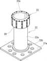
本実施の形態の移動体1は、図1及び図2に示すように、伸縮機構2及び駆動部3を備えている。伸縮機構2は、伸縮部4及び基台部5を備えている。伸縮部4は、詳細は後述するが、テレスコピック式の伸縮可能な筒状体であり、例えば、当該伸縮部4の上端部にプレート6が設けられている。 A moving
基台部5は、詳細は後述するが、伸縮部4を伸縮可能に支持する。基台部5の下面における前端部及び後端部には、例えば、自在キャスター5aが設けられている。基台部5は、例えば、カバー7によって覆われているとよい。ここで、図1及び図2では、移動体1の構成が明確になるように、プレート6やカバー7を二点鎖線で示している。 The
駆動部3は、左右の駆動輪3a及び図示を省略したモーターなどを備えている。左右の駆動輪3a及びモーターなどは、基台部5に支持されている。このような移動体1は、例えば、左右の駆動輪3aを個別に回転駆動することで、前進、後進及び旋回する。そして、伸縮部4が上下方向に伸縮することで、プレート6が上下方向に変位する。ちなみに、移動体1は、自立制御によって動作してもよく、外部からの指示によって動作してもよい。 The
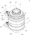
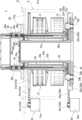
次に、本実施の形態の伸縮機構2の構成を詳細に説明する。図3は、本実施の形態の伸縮機構を示す斜視図である。図4は、本実施の形態の伸縮機構を示す平面図である。図5は、本実施の形態の伸縮機構を示す水平断面図である。図6は、本実施の形態の伸縮機構を示す縦断面図である。図7は、本実施の形態の伸縮部を説明するための図である。図8は、本実施の形態の伸縮機構のメインシャフトなどを示す斜視図である。図9は、本実施の形態の伸縮機構のスクリューシャフトを示す斜視図である。図10は、本実施の形態の伸縮機構のベルトガイドを示す斜視図である。図11は、本実施の形態の伸縮機構の第1のベルトホルダーを示す斜視図である。図12は、本実施の形態の伸縮機構の第1のローラー保持部を示す斜視図である。図13は、本実施の形態の伸縮機構のローラーユニットを示す斜視図である。 Next, the configuration of the
本実施の形態の伸縮機構2は、既に上述したが、図3乃至図6に示すように、伸縮部4及び基台部5を備えている。伸縮部4は、図7に示すように、第1のベルト11及び第2のベルト12を備えている。第1のベルト11は、例えば、鋼製の帯状体であり、向かい合う長辺に沿って略等しい間隔で係合ピン11aが設けられている。第2のベルト12は、例えば、第1のベルト11と等しい太さの鋼製の帯状体であり、向かい合う長辺に沿って、係合ピン11aのピッチに対応するように係合孔12aが設けられている。 As already described above, the
このような第1のベルト11及び第2のベルト12は、予め第1のベルト11の内側に第2のベルト12が配置され、相互にずれた状態で螺旋状に巻かれて伸縮部4を形成する。このとき、第1のベルト11の係合ピン11aは、伸縮部4の内側に向かって突出し、第1のベルト11の上辺の係合ピン11aが当該第1のベルト11に対して上側にずらして配置された第2のベルト12の下辺の係合孔12aに係合され、第1のベルト11の下辺の係合ピン11aが当該第1のベルト11に対して下側にずらして配置された第2のベルト12の上辺の係合孔12aに係合される。 The
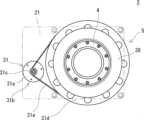
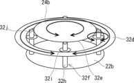
基台部5は、図3乃至図6に示すように、フレーム21、メインシャフト22、第1のローラー保持部23、スクリューシャフト24、ベルトガイド25、第1のベルトホルダー26、第2のベルトホルダー27、第2のローラー保持部28、第1のローラーユニット29、第2のローラーユニット30、第1の駆動部31及び第2の駆動部32を備えている。ここで、図3乃至図6では、伸縮機構2の構成が明確になるように、フレーム21を二点鎖線で示している。 As shown in FIGS. 3 to 6, the
フレーム21は、図3に示すように、第1のプレート21a、第2のプレート21b及び支柱21cを備えている。第1のプレート21aは、略平坦な上面を有する板状体である。第2のプレート21bは、略平坦な上面を有する板状体であり、第1のプレート21aに対して上側に配置されている。そして、第2のプレート21bには、貫通孔が形成されている。支柱21cは、第1のプレート21aの縁部に配置されており、第1のプレート21aと第2のプレート21bとを連結する。 The
メインシャフト22は、図8に示すように、筒状部22a及び当該筒状部22aの下端部から外側に突出するフランジ部22bを備えており、メインシャフト22の下端部が第1のプレート21aに回転可能に支持されている。このようなメインシャフト22における筒状部22aの上端部は、図6に示すように、フレーム21における第2のプレート21bの貫通孔に通された状態で当該第2のプレート21bから上側に突出している。 As shown in FIG. 8, the
第1のローラー保持部23は、図8に示すように、筒状体であり、当該第1のローラー保持部23の外周面に上下方向に延在する溝部23aが形成されている。溝部23aは、例えば、第1のローラー保持部23の周方向で略等しい間隔で配置されている。このような第1のローラー保持部23は、メインシャフト22における筒状部22aの上端部に固定されている。 As shown in FIG. 8, the first
スクリューシャフト24は、図9に示すように、筒状部24a及びフランジ部24bを備えている。筒状部24aの外周面には、第1のベルト11の係合ピン11aが挿入される、螺旋状の溝部24cが形成されている。フランジ部24bは、筒状部24aの下端部から外側に突出している。 The
そして、図6に示すように、スクリューシャフト24の内部にメインシャフト22の筒状部22aが通され、当該メインシャフト22に対してスクリューシャフト24が回転可能な状態で、メインシャフト22のフランジ部22bと第1のローラー保持部23との間に配置されている。 6, the
ベルトガイド25は、図10に示すように、筒状体を基本形態としており、第1の外径を有する第1の部分25a、及び第1の外径に対して小さい第2の外径を有し、第1の部分25aに対して上側に配置された第2の部分25bを備えている。 As shown in FIG. 10, the
ベルトガイド25の第1の部分25aには、第2のベルト12が通される開口部25cが形成されている。ベルトガイド25の第2の部分25bには、第1のベルト11が通される開口部25dが形成されている。 The
そして、図6に示すように、ベルトガイド25の内部にスクリューシャフト24の筒状部24aが通され、ベルトガイド25の下端部がスクリューシャフト24のフランジ部24bに固定されている。 6, the
これにより、スクリューシャフト24とベルトガイド25とは、メインシャフト22を中心に回転可能である。このとき、スクリューシャフト24の筒状部24aの外周面とベルトガイド25の内周面との間には、第1のベルト11と第2のベルト12とが重ねられた状態で通過することができる隙間が形成されている。 Thereby, the
第1のベルトホルダー26は、伸縮部4を形成する前のベルト状態の第2のベルト12を収容する。第1のベルトホルダー26は、図11に示すように、有底の筒状体を基本形態としており、第1のベルトホルダー26の底部に貫通孔26aが形成されている。 The
そして、図6に示すように、第1のベルトホルダー26の貫通孔26aにベルトガイド25が通され、ベルトガイド25に対して第1のベルトホルダー26が回転可能な状態で、第1のベルトホルダー26がスクリューシャフト24のフランジ部24bに支持されている。 6, the
第2のベルトホルダー27は、伸縮部4を形成する前のベルト状態の第1のベルト11を収容する。第2のベルトホルダー27は、第1のベルトホルダー26と略等しい形状とされており、第2のベルトホルダー27の底部に貫通孔27aが形成されている。 The
第2のベルトホルダー27は、図6に示すように、第1のベルトホルダー26に対して上側に配置されている。そして、第2のベルトホルダー27の貫通孔27aにベルトガイド25が通され、ベルトガイド25に対して第2のベルトホルダー27が回転可能な状態で、第2のベルトホルダー27がベルトガイド25における第1の部分25aと第2の部分25bとの段差部に支持されている。 The
第2のローラー保持部28は、図12に示すように、筒状部28a及びフランジ部28bを備えている。筒状部28aは、第1のローラー保持部23の外径に対して大きい内径を有し、筒状部28aの内周面に上下方向に延在する溝部28cが形成されている。溝部28cは、例えば、筒状部28aの周方向で略等しい間隔で配置されている。フランジ部28bは、筒状部28aの下端部から外側に突出するように形成されている。 As shown in FIG. 12, the second
そして、図6に示すように、第2のローラー保持部28の内部に第1のローラー保持部23が通された状態で、第2のローラー保持部28のフランジ部28bがフレーム21の第2のプレート21bに固定されている。このとき、図5に示すように、第1のローラー保持部23の溝部23aと第2のローラー保持部28の溝部28cとは、大凡、対向するように配置されているとよい。 Then, as shown in FIG. 6, the
第1のローラーユニット29は、図13に示すように、ローラー29a及び固定治具29bを備えている。ローラー29aは、略水平方向に延在する回転軸29cを中心に回転可能であり、上下方向に複数並べられている。 The
固定治具29bは、当該固定治具29bを上下方向から見て略C字形状に形成されており、固定治具29bの内部にローラー29aが配置された状態で、回転軸29cを介してローラー29aを支持する。このような第1のローラーユニット29は、第1のローラー保持部23の溝部23aに嵌め込まれて固定されている。 The fixing
第2のローラーユニット30は、第1のローラーユニット29と等しい構成とされているため、詳細な説明を省略するが、上下方向に複数並べられたローラー30aが回転軸30cを介して固定治具30bに回転可能に固定された構成である。このような第2のローラーユニット30は、図12に示すように、第2のローラー保持部28の溝部28cに嵌め込まれて固定されている。 Since the
このとき、第1のローラーユニット29のローラー29aと、第2のローラーユニット30のローラー30aと、の間には、第1のベルト11と第2のベルト12とを重ねた状態で通過することができる隙間が形成されており、当該隙間を上下方向から見た場合、スクリューシャフト24の筒状部24aの外周面とベルトガイド25の内周面との隙間と略重なるように配置されている。 At this time, between the
そして、第1のベルト11と第2のベルト12とが重なった状態で第1のローラーユニット29のローラー29aと第2のローラーユニット30のローラー30aとの隙間を通過した際に、第1のローラーユニット29のローラー29aが第2のベルト12の内周面と接触し、第2のローラーユニット30のローラー30aが第1のベルト11の外周面に接触するように、第1のローラーユニット29のローラー29a及び第2のローラーユニット30のローラー30aが配置されている。 Then, when the
第1の駆動部31は、図6に示すように、モーター31a及び駆動伝達部31bを備えている。モーター31aは、詳細な図示を省略するが、フレーム21の第2のプレート21bに支持されている。駆動伝達部31bは、ピニオンギヤ31c、プーリー31d及びベルト31eを備えている。 The
ピニオンギヤ31cは、モーター31aの出力軸に固定されている。プーリー31dは、外周面に歯部が形成されたリングギヤであり、プーリー31dの内周部がベルトガイド25の上端部に駆動力を伝達可能に固定されている。ベルト31eは、ベルト31eの内周面に歯部が形成された無端ベルトであり、ピニオンギヤ31cとプーリー31dとに掛け渡されている。 The
第2の駆動部32は、図6に示すように、モーター32a及び駆動伝達部32bを備えている。モーター32aは、詳細な図示を省略するが、フレーム21の第1のプレート21aに支持されている。駆動伝達部32bは、ピニオンギヤ32c、リングギヤ32d、外歯部32e、遊星ギヤ32f及びベルト32gを備えている。 The
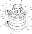
図14は、本実施の形態の伸縮機構における第2の駆動部の駆動伝達部を説明するための斜視図である。図15は、本実施の形態の伸縮機構における第2の駆動部の駆動伝達部を説明するための平面図である。図16は、本実施の形態の伸縮機構における第2の駆動部の遊星ギヤ周辺を拡大して示す断面図である。 FIG. 14 is a perspective view for explaining the drive transmission section of the second drive section in the telescopic mechanism of the present embodiment. FIG. 15 is a plan view for explaining the drive transmission section of the second drive section in the expansion mechanism of the present embodiment. FIG. 16 is an enlarged cross-sectional view showing the periphery of the planetary gear of the second driving section in the expansion mechanism of the present embodiment.
ピニオンギヤ32cは、図6に示すように、モーター32aの出力軸に固定されている。リングギヤ32dは、図6及び図16に示すように、メインシャフト22のフランジ部22bに回転可能に支持されており、リングギヤ32dの外周面及び内周面に歯部が形成されている。外歯部32eは、スクリューシャフト24のフランジ部24bの外周面に形成されている。 The
遊星ギヤ32fは、図14及び図16に示すように、回転軸32h、第1のギヤ部32i及び第2のギヤ部32jを備えている。回転軸32hは、上下方向に延在しており、回転軸32hの下端部がメインシャフト22のフランジ部22bに回転可能に支持されている。第1のギヤ部32iは、図14乃至図16に示すように、回転軸32hに設けられた歯車であり、リングギヤ32dの内周面に形成された歯部に噛み合わされている。 As shown in FIGS. 14 and 16, the
第2のギヤ部32jは、図14及び図16に示すように、回転軸32hに設けられた歯車であり、スクリューシャフト24のフランジ部24bに形成された外歯部32eに噛み合わされている。このとき、図示例では、第2のギヤ部32jが第1のギヤ部32iに対して上側に配置されているが、第2のギヤ部32jが第1のギヤ部32iに対して下側に配置されていてもよい。 14 and 16, the
このような第1の駆動部31及び第2の駆動部32は、第1の駆動部31によってスクリューシャフト24を回転させるために当該スクリューシャフト24に伝達される回転速度と、第2の駆動部32によってスクリューシャフト24を回転させるために当該スクリューシャフト24に伝達される回転速度と、が等しい場合、メインシャフト22を介して伸縮部4が旋回し、相互の回転速度が異なる場合、伸縮部4が伸縮する。 In the
言い換えると、第1の駆動部31によるスクリューシャフト24を回転させるための当該スクリューシャフト24の回転速度と、第2の駆動部32によるスクリューシャフト24を回転させるための当該スクリューシャフト24の回転速度と、が等しい場合、メインシャフト22を介して伸縮部4が旋回し、相互の回転速度が異なる場合、伸縮部4が伸縮する。ここで、「回転速度」は、移動体1を上側から見て、スクリューシャフト24の一方への回転を「+」とし、スクリューシャフト24の他方への回転を「-」とするものである。 In other words, when the rotational speed of the
この場合、第1の駆動部31及び第2の駆動部32は、例えば、以下の条件を満たすとよい。伸縮部4の伸縮動作は、メインシャフト22とスクリューシャフト24との回転量の差となるので、以下の<数1>で表すことができる。
ここで、vpは伸縮部4の伸縮速度、pはスクリューシャフト24の溝部24cのピッチ長さ、ωsはスクリューシャフト24の回転速度、ωmはメインシャフト22の回転速度を示す。Here,vp is the expansion/contraction speed of the expansion/
このとき、メインシャフト22に対するフレーム21の回転速度ωpは、メインシャフト22の回転速度に一致するので、以下の<数2>で表すことができる。
そして、遊星ギヤ32fの関係から以下の<数3>を満たす。
ここで、Z1は遊星ギヤ32fの第2のギヤ部32jの歯数、Zsはスクリューシャフト24のフランジ部24bに形成された外歯部32eの歯数、ωyは遊星ギヤ32fの自転速度、ωiはリングギヤ32dの回転速度、Z2は遊星ギヤ32fの第1のギヤ部32iの歯数、Ziはリングギヤ32dの内周面に形成された歯部の歯数を示す。Here,Z1 is the number of teeth of the
このとき、<数4>と仮定する。
以上から、ωyを消去して<数5>を導き出すことができる。
よって、<数6>とすると、<数7>を導き出すことができる。

逆行列を用いれば、<数8>で表すことができる。
また、静力学的関係から<数9>で表すことができる。
ここで、τsはスクリューシャフト24に入力されるトルク、τiはリングギヤ32dに入力されるトルク、Fpは伸縮部4の伸縮力、TPはメインシャフト22に対するフレーム21の出力トルクを示す。Here, τs is the torque input to the
そして、伸縮部4が伸縮動作のみの場合、以下の<数10>及び<数11>の条件を満たすと、<数12>及び<数13>で表すことができる。


一方、伸縮部4が旋回動作のみの場合、以下の<数14>及び<数15>の条件を満たすと、<数16>及び<数17>で表すことができる。


したがって、伸縮部4の伸縮動作及び旋回動作の何れの場合においても、第1の駆動部31のモーター31aと第2の駆動部32のモーター32aとの出力を合成することができる。 Therefore, the output of the
なお、途中で仮定した<数4>は、第1の駆動部31のモーター31a及び第2の駆動部32のモーター32aから同等の出力を得られる場合に上記の関係を得るためのものであるため、第1の駆動部31のモーター31aと第2の駆動部32のモーター32aとの出力が異なる場合などは、必ずしも<数4>を満たす必要はない。 Note that <
次に、本実施の形態の伸縮機構2の伸縮部4が伸縮する際の動作を説明する。第1の駆動部31によってスクリューシャフト24を回転させるために当該スクリューシャフト24に伝達される回転速度と、第2の駆動部32によってスクリューシャフト24を回転させるために当該スクリューシャフト24に伝達される回転速度と、が異なるように、第1の駆動部31のモーター31a及び第2の駆動部32のモーター32aを回転駆動させ、第1の駆動部31の駆動伝達部31b及びベルトガイド25を介してモーター31aの回転駆動力をスクリューシャフト24に伝達すると共に、第2の駆動部32の駆動伝達部32bを介してモーター32aの回転駆動力をメインシャフト22及びスクリューシャフト24に伝達する。 Next, the operation when the expansion/
これにより、メインシャフト22に対してスクリューシャフト24が差動回転し、スクリューシャフト24の回転に伴って、第1のベルト11及び第2のベルト12が引き出されて螺旋状に巻回しつつ伸縮部4が伸長、又は第1のベルト11と第2のベルト12とが係合して巻回した状態がほどけつつ伸縮部4が収縮する。 As a result, the
このとき、本実施の形態の移動体1及び伸縮機構2においては、伸縮部4の下部を当該伸縮部4の厚さ方向で第1のローラーユニット29のローラー29aと第2のローラーユニット30のローラー30aとで挟み込むため、伸縮部4の振れを抑制することができる。 At this time, in the moving
次に、本実施の形態の伸縮機構2の伸縮部4が旋回する際の動作を説明する。第1の駆動部31によってスクリューシャフト24を回転させるために当該スクリューシャフト24に伝達される回転速度と、第2の駆動部32によってスクリューシャフト24を回転させるために当該スクリューシャフト24に伝達される回転速度と、が等しくなるように、第1の駆動部31のモーター31a及び第2の駆動部32のモーター32aを回転駆動させ、第1の駆動部31の駆動伝達部31b及びベルトガイド25を介してモーター31aの回転駆動力をスクリューシャフト24に伝達すると共に、第2の駆動部32の駆動伝達部32bを介してモーター32aの回転駆動力をメインシャフト22及びスクリューシャフト24に伝達する。 Next, the operation when the
これにより、メインシャフト22とスクリューシャフト24とが等しく回転し、メインシャフト22、スクリューシャフト24、ベルトガイド25及び伸縮部4が一体的に回転し、その結果、基台部5に対して伸縮部4が旋回する。 As a result, the
このように本実施の形態の移動体1及び伸縮機構2においては、伸縮部4の下部に第1のローラーユニット29のローラー29a又は第2のローラーユニット30のローラー30aの少なくとも一方が接触するため、伸縮部4の振れを抑制することができる。つまり、第1のローラーユニット29のローラー29a及び第2のローラーユニット30のローラー30aは、伸縮部4の振れを抑制するための支持部として機能する。 As described above, in the moving
このとき、第1のローラーユニット29のローラー29aと第2のローラーユニット30のローラー30aとは、伸縮部4の厚さ方向で向かい合うように配置されているとよい。これにより、第1のローラーユニット29のローラー29aと第2にのローラーユニット30のローラー30aとで伸縮部4の下部を確実に挟み込むことができる。 At this time, the
しかも、第1のローラーユニット29のローラー29a及び第2のローラーユニット30のローラー30aは、伸縮部4の伸縮方向である上下方向に並べられているので、伸縮部4の伸縮に倣ってローラー29a、30aがスムーズに回転し、相互の摩擦を軽減することができ、ローラー29a、30aの摩耗を抑制することができる。 Moreover, since the
また、第1のローラーユニット29のローラー29aは、第2のベルト12における伸縮部4の伸縮方向で隣接する隙間のピッチと異なる間隔で配置されているとよい。これにより、第1のローラーユニット29のローラー29aの全てが伸縮部4の伸縮方向で隣接する第2のベルト12の隙間と干渉せず、当該ローラー29aの何れかが第2のベルト12に接触する。 Further, the
同様に、第2のローラーユニット30のローラー30aは、第1のベルト11における伸縮部4の伸縮方向で隣接する隙間のピッチと異なる間隔で配置されているとよい。これにより、第2のローラーユニット30のローラー30aの全てが伸縮部4の伸縮方向で隣接する第1のベルト11の隙間と干渉せず、当該ローラー30aの何れかが第1のベルト11に接触する。そのため、伸縮部4の振れをより抑制することができる。 Similarly, the
さらに、第1のローラーユニット29のローラー29aは、第1のベルト11の係合ピン11aを避けるように配置されているとよい。これにより、第1のローラーユニット29のローラー29aを第1のベルト11に確実に接触させることができる。 Furthermore, the
ちなみに、図17に示すように、第1のローラーユニット29のローラー29a又は第2のローラーユニット30のローラー30aの少なくとも一方は、バネなどの付勢部材33によって伸縮部4の側に付勢されているとよい。これにより、第1のローラーユニット29のローラー29a又は第2のローラーユニット30のローラー30aの少なくとも一方は確実に伸縮部4に接触させることができる。 Incidentally, as shown in FIG. 17, at least one of the
また、本実施の形態の移動体1又は伸縮機構2は、第1の駆動部31及び第2の駆動部32によって伸縮部4の伸縮動作と旋回動作とを実現することができる。しかも、第1の駆動部31のモーター31aと第2の駆動部32のモーター32aとの出力を合成して、伸縮部4の伸縮動作と旋回動作とを実現することができる。そのため、2個のモーターを用いて、各々のモーターの出力で個別に伸縮部4の伸縮動作と旋回動作とを実現する場合に比べて、モーター31a、32aを小型化することができ、その結果、移動体1の小型化及び軽量化に寄与できる。 Further, the moving
<実施の形態2>
実施の形態1の伸縮機構2においては、第2のローラー保持部28を非回転の構成としているが、第2のローラー保持部をベルトガイド25と共に回転させてもよい。ここで、図18は、本実施の形態の伸縮機構を示す斜視図である。<
In the
例えば、第2のローラー保持部41は、図18に示すように、螺旋状に巻回される第1のベルト11の傾斜に沿うように斜めに配置したローラー42が設けられており、ベルトガイド25の上端部に固定されている。 For example, as shown in FIG. 18, the second
ローラー42は、伸縮部4の回転量と当該伸縮部4の伸縮量とに基づいて導き出される第1のベルト11の傾斜角度と直交する回転軸43を中心に回転可能とされている。そして、ローラー42は、第2のローラー保持部41に形成された貫通孔41aを介して当該第2のローラー保持部41の内周面から突出している。 The
このような構成により、ローラー42が第1のベルト11における伸縮部4の伸縮方向の等しい高さ位置に常に接触するため、伸縮部4が伸縮する際のローラー42と第1のベルト11の隙間との干渉を簡単に避けることができる。 With such a configuration, the
ちなみに、第1のローラー保持部も、第2のローラー保持部41と略同様の構成とし、ローラーが第2のベルト12の傾斜に沿うように斜めに設けられているとよい。 Incidentally, it is preferable that the first roller holding portion has substantially the same configuration as the second
本開示は上記実施の形態に限られたものではなく、趣旨を逸脱しない範囲で適宜変更することが可能である。
例えば、上記実施の形態の伸縮機構は、伸縮部4が旋回可能な構成としているが、旋回不能な構成とされていてもよい。
例えば、上記実施の形態の伸縮機構は、伸縮部4の根元の振れを抑制するために第1のローラーユニット29及び第2のローラーユニット30を備えているが、少なくとも伸縮部4の根元部の内周面又は外周面に接触する支持部を備えていればよい。The present disclosure is not limited to the above embodiments, and can be modified as appropriate without departing from the spirit of the present disclosure.
For example, in the telescopic mechanism of the above embodiment, the
For example, the telescopic mechanism of the above embodiment includes the
1 移動体
2 伸縮機構
3 駆動部、3a 駆動輪
4 伸縮部
5 基台部、5a 自在キャスター
6 プレート
7 カバー
11 第1のベルト、11a 係合ピン
12 第2のベルト、12a 係合孔
21 フレーム、21a 第1のプレート、21b 第2のプレート、21c 支柱
22 メインシャフト、22a 筒状部、22b フランジ部
23 第1のローラー保持部、23a 溝部
24 スクリューシャフト、24a 筒状部、24b フランジ部、24c 溝部
25 ベルトガイド、25a 第1の部分、25b 第2の部分、25c、25d 開口部
26 第1のベルトホルダー、26a 貫通孔
27 第2のベルトホルダー、27a 貫通孔
28 第2のローラー保持部、28a 筒状部、28b フランジ部、28c 溝部
29 第1のローラーユニット、29a ローラー、29b 固定治具、29c 回転軸
30 第2のローラーユニット、30a ローラー、30b 固定治具、30c 回転軸
31 第1の駆動部
31a モーター
31b 駆動伝達部、31c ピニオンギヤ、31d プーリー、31e ベルト
32 第2の駆動部
32a モーター
32b 駆動伝達部
32c ピニオンギヤ
32d リングギヤ
32e 外歯部
32f 遊星ギヤ、32h 回転軸、32i 第1のギヤ部、32j 第2のギヤ部
32g ベルト
33 付勢部材
41 第2のローラー保持部、41a 貫通孔
42 ローラー
43 回転軸
Claims (7)
Translated fromJapanese前記基台部に対する前記伸縮部の根元側の部分の揺れを抑制するために、前記伸縮部の内周面に接触する第1のローラーユニットと、前記伸縮部の外周面に接触する第2のローラーユニットと、を有する支持部を備え、
前記第1のローラーユニットは、前記基台部における前記伸縮部の内周面と向かい合う側面に設けられ、前記第2のローラーユニットは、前記基台部における前記伸縮部の外周面と向かい合う側面に設けられ、
前記伸縮部は、第1のベルトと第2のベルトとを備え、
前記第1のベルトと前記第2のベルトとは、相互にずらして係合された状態で螺旋状に巻回されており、
前記第1のローラーユニットのローラー又は前記第2のローラーユニットのローラーは、前記第1のベルト又は前記第2のベルトにおける前記伸縮部の伸縮方向で隣接する隙間のピッチと異なる間隔で配置されている、伸縮機構。An expansion and contraction mechanism comprising a telescopic expansion and contraction section and a base section that supports the expansion and contraction section in an expandable and contractable manner,
A support portionhaving a first roller unit that contacts the inner peripheral surface of the expandable portion and a second rollerunit that contacts the outer peripheral surface of the expandable portion in order to suppress shaking of the root side portion of the expandable portion with respect to thebase portion,
The first roller unit is provided on a side surfaceof the base portionfacing the inner peripheralsurfaceof the expandable portion, and the second roller unit is provided on the side surface of the base portion facing the outer peripheral surface of the expandable portion,
The stretchable section includes a first belt and a second belt,
The first belt and the second belt are spirally wound in a state of being mutually shifted and engaged,
The rollers of the first roller unit or the rollers of the second roller unit are arranged at intervals different from the pitch of adjacent gaps in the stretching direction of the stretching portion of the first belt or the second belt.
Priority Applications (4)
| Application Number | Priority Date | Filing Date | Title |
|---|---|---|---|
| JP2020080136AJP7314857B2 (en) | 2020-04-30 | 2020-04-30 | Telescopic mechanism and moving body |
| US17/221,991US11371593B2 (en) | 2020-04-30 | 2021-04-05 | Extension/contraction mechanism and mobile body |
| CA3115053ACA3115053A1 (en) | 2020-04-30 | 2021-04-13 | Extension/contraction mechanism and mobile body |
| CN202110465647.1ACN113586567B (en) | 2020-04-30 | 2021-04-28 | Telescoping mechanism and moving body |
Applications Claiming Priority (1)
| Application Number | Priority Date | Filing Date | Title |
|---|---|---|---|
| JP2020080136AJP7314857B2 (en) | 2020-04-30 | 2020-04-30 | Telescopic mechanism and moving body |
Publications (2)
| Publication Number | Publication Date |
|---|---|
| JP2021173391A JP2021173391A (en) | 2021-11-01 |
| JP7314857B2true JP7314857B2 (en) | 2023-07-26 |
Family
ID=78243212
Family Applications (1)
| Application Number | Title | Priority Date | Filing Date |
|---|---|---|---|
| JP2020080136AActiveJP7314857B2 (en) | 2020-04-30 | 2020-04-30 | Telescopic mechanism and moving body |
Country Status (4)
| Country | Link |
|---|---|
| US (1) | US11371593B2 (en) |
| JP (1) | JP7314857B2 (en) |
| CN (1) | CN113586567B (en) |
| CA (1) | CA3115053A1 (en) |
Families Citing this family (9)
| Publication number | Priority date | Publication date | Assignee | Title |
|---|---|---|---|---|
| JP2024502536A (en)* | 2021-01-12 | 2024-01-22 | ゲスチョン・ラフォレスト・インコーポレイテッド | Linear actuator with anti-rotation mechanism |
| JP7632401B2 (en) | 2022-06-27 | 2025-02-19 | トヨタ自動車株式会社 | Extendable pipe and transport robot |
| JP2024063832A (en)* | 2022-10-27 | 2024-05-14 | トヨタ自動車株式会社 | Telescopic mechanism |
| JP2024081904A (en)* | 2022-12-07 | 2024-06-19 | トヨタ自動車株式会社 | Helical advance/retract actuator, belt for cylindrical telescopic body, and method for manufacturing belt for cylindrical telescopic body |
| JP2024082899A (en) | 2022-12-09 | 2024-06-20 | トヨタ自動車株式会社 | Telescopic mechanism |
| JP2024101744A (en)* | 2023-01-18 | 2024-07-30 | トヨタ自動車株式会社 | Expansion device |
| JP2024152426A (en)* | 2023-04-14 | 2024-10-25 | トヨタ自動車株式会社 | Spiral advance/retract actuator |
| JP7750261B2 (en)* | 2023-04-18 | 2025-10-07 | トヨタ自動車株式会社 | Transport System |
| JP7750262B2 (en)* | 2023-04-18 | 2025-10-07 | トヨタ自動車株式会社 | telescopic device |
Citations (9)
| Publication number | Priority date | Publication date | Assignee | Title |
|---|---|---|---|---|
| US4819495A (en) | 1986-02-01 | 1989-04-11 | Hormann Kg Antriebs- Und Steuerungstechnik | Gear for converting a rotary into a translational motion |
| JP2002195488A (en) | 2000-12-28 | 2002-07-10 | Sanko Spring Kk | Telescopic pipe device |
| JP2008504190A (en) | 2004-07-01 | 2008-02-14 | ゲスチョン・ラフォレスト・インコーポレイテッド | Linear actuator with releasable coupling band |
| JP2016101652A (en) | 2014-11-29 | 2016-06-02 | ライフロボティクス株式会社 | Robot arm mechanism |
| JP2016124068A (en) | 2014-12-27 | 2016-07-11 | ライフロボティクス株式会社 | Robot arm mechanism and direct-acting expansion mechanism |
| DE102016000568A1 (en) | 2016-01-20 | 2017-07-20 | Iwis Antriebssysteme Gmbh & Co. Kg | Actuator with a back-stiff chain |
| CN107381428A (en) | 2017-08-02 | 2017-11-24 | 芜湖昊葛金自动化科技有限公司 | A kind of hoisting machine people dolly |
| JP2019138356A (en) | 2018-02-08 | 2019-08-22 | 吉田メカテック株式会社 | Spiral movement actuator |
| WO2020039870A1 (en) | 2018-08-24 | 2020-02-27 | 株式会社ライトボーイ | Projector |
Family Cites Families (19)
| Publication number | Priority date | Publication date | Assignee | Title |
|---|---|---|---|---|
| US2130993A (en)* | 1936-07-02 | 1938-09-20 | Dubiller William | Collapsible rod |
| US3243132A (en)* | 1963-04-01 | 1966-03-29 | Dehavilland Aircraft Canada | Extensible retractable stem device |
| US3360894A (en)* | 1966-06-20 | 1968-01-02 | Melpar Inc | Extendible interlocked boom |
| DE3419477C1 (en)* | 1984-05-24 | 1985-11-28 | Hörmann KG Antriebs- und Steuerungstechnik, 4834 Harsewinkel | Gearbox for converting a rotary into a translatory movement |
| DE3838724A1 (en)* | 1987-12-07 | 1989-06-22 | Schmid Hans Armin | DEVICE FOR CARRYING A BOMBED TAPE |
| ATE67464T1 (en)* | 1988-02-02 | 1991-10-15 | Pierre Gagnon | LIFT JACK. |
| CA2109051A1 (en)* | 1993-10-22 | 1995-04-23 | Norbert Hamy | Linear actuator |
| NO324735B1 (en)* | 2003-03-26 | 2007-12-03 | Bjarte Langeland | Rigid rudder and method for producing a rigid rudder |
| JP4607772B2 (en) | 2006-01-17 | 2011-01-05 | 吉田メカテック株式会社 | Helical advance / retreat device |
| US20110126650A1 (en)* | 2008-05-08 | 2011-06-02 | Kataka A/S | Actuator, chain and method of use |
| JP5066026B2 (en)* | 2008-07-16 | 2012-11-07 | 株式会社ピカコーポレイション | Telescopic locking mechanism |
| AU2013200923B1 (en)* | 2013-02-19 | 2013-09-12 | Bos Fabrication Engineering Services Pty Ltd | Jack assembly for a jockey wheel |
| US10050342B1 (en)* | 2014-09-10 | 2018-08-14 | Lockheed Martin Corporation | Self deploying axial drive actuator |
| JP6399591B2 (en)* | 2014-10-31 | 2018-10-03 | ライフロボティクス株式会社 | Robot arm mechanism and stepping motor control device |
| DE112017001656B4 (en)* | 2016-03-29 | 2022-12-22 | Life Robotics Inc. | Robot arm mechanism and pivot device |
| EP3260250B1 (en)* | 2016-06-21 | 2019-10-02 | Ansaldo Energia IP UK Limited | Robotic system for confined space operations background |
| CN105952747A (en)* | 2016-07-05 | 2016-09-21 | 张奉果 | Telescopic device |
| JP6659846B2 (en)* | 2016-07-30 | 2020-03-04 | ライフロボティクス株式会社 | Robot arm mechanism |
| DE102017207251B4 (en)* | 2017-04-28 | 2025-10-02 | Schaeffler Technologies AG & Co. KG | Telescopic column |
- 2020
- 2020-04-30JPJP2020080136Apatent/JP7314857B2/enactiveActive
- 2021
- 2021-04-05USUS17/221,991patent/US11371593B2/enactiveActive
- 2021-04-13CACA3115053Apatent/CA3115053A1/ennot_activeAbandoned
- 2021-04-28CNCN202110465647.1Apatent/CN113586567B/enactiveActive
Patent Citations (10)
| Publication number | Priority date | Publication date | Assignee | Title |
|---|---|---|---|---|
| US4819495A (en) | 1986-02-01 | 1989-04-11 | Hormann Kg Antriebs- Und Steuerungstechnik | Gear for converting a rotary into a translational motion |
| JP2002195488A (en) | 2000-12-28 | 2002-07-10 | Sanko Spring Kk | Telescopic pipe device |
| JP2008504190A (en) | 2004-07-01 | 2008-02-14 | ゲスチョン・ラフォレスト・インコーポレイテッド | Linear actuator with releasable coupling band |
| JP2016101652A (en) | 2014-11-29 | 2016-06-02 | ライフロボティクス株式会社 | Robot arm mechanism |
| US20170266819A1 (en) | 2014-11-29 | 2017-09-21 | Life Robotics Inc. | Robot arm mechanism |
| JP2016124068A (en) | 2014-12-27 | 2016-07-11 | ライフロボティクス株式会社 | Robot arm mechanism and direct-acting expansion mechanism |
| DE102016000568A1 (en) | 2016-01-20 | 2017-07-20 | Iwis Antriebssysteme Gmbh & Co. Kg | Actuator with a back-stiff chain |
| CN107381428A (en) | 2017-08-02 | 2017-11-24 | 芜湖昊葛金自动化科技有限公司 | A kind of hoisting machine people dolly |
| JP2019138356A (en) | 2018-02-08 | 2019-08-22 | 吉田メカテック株式会社 | Spiral movement actuator |
| WO2020039870A1 (en) | 2018-08-24 | 2020-02-27 | 株式会社ライトボーイ | Projector |
Also Published As
| Publication number | Publication date |
|---|---|
| US20210341041A1 (en) | 2021-11-04 |
| CA3115053A1 (en) | 2021-10-30 |
| CN113586567A (en) | 2021-11-02 |
| US11371593B2 (en) | 2022-06-28 |
| CN113586567B (en) | 2023-05-05 |
| JP2021173391A (en) | 2021-11-01 |
Similar Documents
| Publication | Publication Date | Title |
|---|---|---|
| JP7314857B2 (en) | Telescopic mechanism and moving body | |
| JP7276241B2 (en) | Telescopic mechanism and moving body | |
| US8460154B2 (en) | Frictional drive device and inverted pendulum type vehicle using the same | |
| JP5506231B2 (en) | Wheel, friction drive using the same, and omnidirectional vehicle | |
| JP2007534540A (en) | Vehicle roof with roller blind device | |
| KR20170062259A (en) | Motion simulator with two degree of freedom angular motion | |
| JP2011063243A (en) | Mobile body | |
| JP2005130920A (en) | Massage machine | |
| CN108908357B (en) | Drive components and robots | |
| JP5102206B2 (en) | Roller actuators for machines used to process metal products | |
| JP2024082899A (en) | Telescopic mechanism | |
| JP2020514166A (en) | Multi-speed bicycle | |
| CN214691624U (en) | A rotary belt conveyor | |
| CN111120804B (en) | Universal mobile platform | |
| JP2017159847A (en) | Traveling device | |
| JPH0777247A (en) | Drive | |
| JP6496283B2 (en) | Cable feeding device | |
| TW201305037A (en) | Paper feeding mechanism | |
| CN221138385U (en) | Running gear and cleaning robot | |
| JP6267978B2 (en) | Belt actuator | |
| JP2021038807A (en) | Rotation transmission device | |
| JP2525667Y2 (en) | Electric curtain equipment | |
| JP2010230436A (en) | Vehicle inspection device | |
| JPWO2021075510A5 (en) | ||
| JP2003507685A (en) | Motor with transmission |
Legal Events
| Date | Code | Title | Description |
|---|---|---|---|
| A621 | Written request for application examination | Free format text:JAPANESE INTERMEDIATE CODE: A621 Effective date:20220422 | |
| A977 | Report on retrieval | Free format text:JAPANESE INTERMEDIATE CODE: A971007 Effective date:20230228 | |
| A131 | Notification of reasons for refusal | Free format text:JAPANESE INTERMEDIATE CODE: A131 Effective date:20230404 | |
| A521 | Request for written amendment filed | Free format text:JAPANESE INTERMEDIATE CODE: A523 Effective date:20230411 | |
| TRDD | Decision of grant or rejection written | ||
| A01 | Written decision to grant a patent or to grant a registration (utility model) | Free format text:JAPANESE INTERMEDIATE CODE: A01 Effective date:20230613 | |
| A61 | First payment of annual fees (during grant procedure) | Free format text:JAPANESE INTERMEDIATE CODE: A61 Effective date:20230626 | |
| R151 | Written notification of patent or utility model registration | Ref document number:7314857 Country of ref document:JP Free format text:JAPANESE INTERMEDIATE CODE: R151 |