JP7314633B2 - Probe pins, inspection fixtures and inspection units - Google Patents
Probe pins, inspection fixtures and inspection unitsDownload PDFInfo
- Publication number
- JP7314633B2 JP7314633B2JP2019108955AJP2019108955AJP7314633B2JP 7314633 B2JP7314633 B2JP 7314633B2JP 2019108955 AJP2019108955 AJP 2019108955AJP 2019108955 AJP2019108955 AJP 2019108955AJP 7314633 B2JP7314633 B2JP 7314633B2
- Authority
- JP
- Japan
- Prior art keywords
- contact portion
- contact
- elastic
- socket
- probe pin
- Prior art date
- Legal status (The legal status is an assumption and is not a legal conclusion. Google has not performed a legal analysis and makes no representation as to the accuracy of the status listed.)
- Active
Links
- 239000000523sampleSubstances0.000titleclaimsdescription81
- 238000007689inspectionMethods0.000titleclaimsdescription55
- 238000013459approachMethods0.000claimsdescription3
- 239000011295pitchSubstances0.000description14
- 238000010586diagramMethods0.000description4
- 230000004308accommodationEffects0.000description3
- 239000011248coating agentSubstances0.000description3
- 238000000576coating methodMethods0.000description3
- 239000004065semiconductorSubstances0.000description3
- 238000012360testing methodMethods0.000description3
- 230000015572biosynthetic processEffects0.000description2
- 238000012986modificationMethods0.000description2
- 230000004048modificationEffects0.000description2
- 238000005452bendingMethods0.000description1
- 230000008602contractionEffects0.000description1
- 230000000694effectsEffects0.000description1
- 238000005323electroformingMethods0.000description1
- 238000003780insertionMethods0.000description1
- 230000037431insertionEffects0.000description1
- 239000004973liquid crystal related substanceSubstances0.000description1
- 238000004519manufacturing processMethods0.000description1
- 230000000149penetrating effectEffects0.000description1
Images


Classifications
- G—PHYSICS
- G01—MEASURING; TESTING
- G01R—MEASURING ELECTRIC VARIABLES; MEASURING MAGNETIC VARIABLES
- G01R1/00—Details of instruments or arrangements of the types included in groups G01R5/00 - G01R13/00 and G01R31/00
- G01R1/02—General constructional details
- G01R1/06—Measuring leads; Measuring probes
- G01R1/067—Measuring probes
- G01R1/06711—Probe needles; Cantilever beams; "Bump" contacts; Replaceable probe pins
- G01R1/06716—Elastic
- G—PHYSICS
- G01—MEASURING; TESTING
- G01R—MEASURING ELECTRIC VARIABLES; MEASURING MAGNETIC VARIABLES
- G01R1/00—Details of instruments or arrangements of the types included in groups G01R5/00 - G01R13/00 and G01R31/00
- G01R1/02—General constructional details
- G01R1/06—Measuring leads; Measuring probes
- G01R1/067—Measuring probes
- G01R1/06711—Probe needles; Cantilever beams; "Bump" contacts; Replaceable probe pins
- G—PHYSICS
- G01—MEASURING; TESTING
- G01R—MEASURING ELECTRIC VARIABLES; MEASURING MAGNETIC VARIABLES
- G01R1/00—Details of instruments or arrangements of the types included in groups G01R5/00 - G01R13/00 and G01R31/00
- G01R1/02—General constructional details
- G01R1/04—Housings; Supporting members; Arrangements of terminals
- G01R1/0408—Test fixtures or contact fields; Connectors or connecting adaptors; Test clips; Test sockets
- G01R1/0416—Connectors, terminals
- G—PHYSICS
- G01—MEASURING; TESTING
- G01R—MEASURING ELECTRIC VARIABLES; MEASURING MAGNETIC VARIABLES
- G01R1/00—Details of instruments or arrangements of the types included in groups G01R5/00 - G01R13/00 and G01R31/00
- G01R1/02—General constructional details
- G01R1/06—Measuring leads; Measuring probes
- G01R1/067—Measuring probes
- G01R1/06711—Probe needles; Cantilever beams; "Bump" contacts; Replaceable probe pins
- G01R1/06733—Geometry aspects
- G—PHYSICS
- G01—MEASURING; TESTING
- G01R—MEASURING ELECTRIC VARIABLES; MEASURING MAGNETIC VARIABLES
- G01R31/00—Arrangements for testing electric properties; Arrangements for locating electric faults; Arrangements for electrical testing characterised by what is being tested not provided for elsewhere
- G01R31/26—Testing of individual semiconductor devices
- G—PHYSICS
- G01—MEASURING; TESTING
- G01R—MEASURING ELECTRIC VARIABLES; MEASURING MAGNETIC VARIABLES
- G01R31/00—Arrangements for testing electric properties; Arrangements for locating electric faults; Arrangements for electrical testing characterised by what is being tested not provided for elsewhere
- G01R31/28—Testing of electronic circuits, e.g. by signal tracer
- G01R31/2851—Testing of integrated circuits [IC]
- G01R31/2855—Environmental, reliability or burn-in testing
- G01R31/286—External aspects, e.g. related to chambers, contacting devices or handlers
- G01R31/2863—Contacting devices, e.g. sockets, burn-in boards or mounting fixtures
- G—PHYSICS
- G01—MEASURING; TESTING
- G01R—MEASURING ELECTRIC VARIABLES; MEASURING MAGNETIC VARIABLES
- G01R31/00—Arrangements for testing electric properties; Arrangements for locating electric faults; Arrangements for electrical testing characterised by what is being tested not provided for elsewhere
- G01R31/50—Testing of electric apparatus, lines, cables or components for short-circuits, continuity, leakage current or incorrect line connections
- G01R31/54—Testing for continuity
Landscapes
- Physics & Mathematics (AREA)
- General Physics & Mathematics (AREA)
- Engineering & Computer Science (AREA)
- Environmental & Geological Engineering (AREA)
- Computer Hardware Design (AREA)
- Microelectronics & Electronic Packaging (AREA)
- General Engineering & Computer Science (AREA)
- Geometry (AREA)
- Measuring Leads Or Probes (AREA)
- Testing Of Individual Semiconductor Devices (AREA)
Description
Translated fromJapanese本開示は、プローブピン、検査治具および検査ユニットに関する。 The present disclosure relates to probe pins, inspection jigs, and inspection units.
カメラあるいは液晶パネル等の電子部品モジュールでは、一般に、その製造工程において、導通検査および動作特性検査等が行われる。これらの検査は、プローブピンを用いて、電子部品モジュールに設置されている本体基板に接続するための端子と、検査装置の端子とを接続することにより行われる。 2. Description of the Related Art Electronic component modules such as cameras and liquid crystal panels are generally subjected to continuity tests, operating characteristic tests, and the like in the manufacturing process. These inspections are performed by using probe pins to connect terminals for connection to the body board installed in the electronic component module and terminals of the inspection device.
このようなプローブピンとしては、特許文献1に記載されたものがある。このプローブピンは、電子部品の電極端子および被接続電子部品の電極端子に対してそれぞれ接触可能な一対のコンタクトと、一対のコンタクト間に介在して一対のコンタクトを接続する蛇行部とを備えている。 As such a probe pin, there is one described in
前記プローブピンでは、蛇行部の伸縮方向に直行する幅方向の中心に一対のコンタクトをそれぞれ配置して、蛇行部を伸縮させた際に各コンタクトが幅方向に倒れないようにしている。このため、複数の前記プローブピンを幅方向に並べて配置すると、隣接する各コンタクトの配置間隔を狭くすることが難しくなり、例えば、狭ピッチ化された電子部品モジュールの一対の端子に対して、各コンタクトを同時に接触させた状態にすることができず、電子部品モジュールの狭ピッチ化に対応することができない場合がある。 In the probe pin, a pair of contacts are arranged at the center in the width direction perpendicular to the extension/contraction direction of the meandering portion so that each contact does not collapse in the width direction when the meandering portion is extended/contracted. Therefore, when a plurality of the probe pins are arranged in the width direction, it becomes difficult to narrow the arrangement interval between adjacent contacts. For example, it may not be possible to bring each contact into contact with a pair of terminals of an electronic component module having a narrow pitch, and it may not be possible to cope with the narrow pitch of the electronic component module.
本開示は、接触対象物の狭ピッチ化に対応可能なプローブピン、このプローブピンを備えた検査治具、および、この検査治具を備えた検査ユニットを提供することを目的とする。 An object of the present disclosure is to provide probe pins that can accommodate narrower pitches of contact objects, an inspection jig that includes the probe pins, and an inspection unit that includes the inspection jig.
本開示の一例のプローブピンは、
第1方向に沿って弾性変形可能な弾性部と、
前記弾性部の前記第1方向の一端が接続された第1接触部と、
前記弾性部の前記第1方向の他端が接続された第2接触部と
を備え、
前記弾性部が、前記第1方向に伸縮可能な状態でソケットに収容可能なプローブピンであって、
前記弾性部が、
前記第1接触部から前記第1方向に交差する第2方向に沿って延びて前記弾性部の前記第1方向の一端を構成する第1当接部と、
前記第2方向において前記第1当接部と前記第2接触部に対する同じ側に配置され、前記第2接触部から前記第2方向に沿って延びて前記弾性部の前記他端を構成する第2当接部と
を有し、
前記第1当接部および前記第2当接部の各々が、前記ソケットに収容された状態で前記第1方向において前記ソケットの内部に当接可能に構成されている。An example probe pin of the present disclosure includes:
an elastic portion elastically deformable along a first direction;
a first contact portion connected to one end of the elastic portion in the first direction;
a second contact portion to which the other end of the elastic portion in the first direction is connected;
A probe pin that can be accommodated in a socket in a state in which the elastic portion can expand and contract in the first direction,
The elastic portion is
a first contact portion extending from the first contact portion along a second direction intersecting the first direction and forming one end of the elastic portion in the first direction;
a second contact portion disposed on the same side with respect to the first contact portion and the second contact portion in the second direction and extending from the second contact portion along the second direction to constitute the other end of the elastic portion;
Each of the first contact portion and the second contact portion is configured to contact the inside of the socket in the first direction while being housed in the socket.
また、本開示の一例の検査治具は、
前記プローブピンと、
前記プローブピンを収容可能な前記ソケットと
を備え、
前記ソケットに前記プローブピンを収容したときに、前記第1当接部および前記第2当接部の各々が、前記第1方向において、前記ソケットの内面に当接するように構成されている。In addition, an inspection jig according to an example of the present disclosure includes:
the probe pin;
and the socket capable of accommodating the probe pin,
Each of the first contact portion and the second contact portion is configured to contact the inner surface of the socket in the first direction when the probe pin is accommodated in the socket.
また、本開示の一例の検査ユニットは、
前記検査治具を少なくとも1つ備える。Also, an example inspection unit of the present disclosure includes:
At least one inspection jig is provided.
前記プローブピンによれば、弾性部が、第1接触部から第2方向に沿って延びて弾性部の一端を構成する第1当接部と、第2方向において第1当接部と第2接触部に対する同じ側に配置され第2接触部から第2方向に沿って延びて弾性部の他端を構成する第2当接部とを有する。第1当接部および第2当接部の各々が、ソケットに収容されたときに第1方向においてソケットの内部に当接可能に構成されている。このような構成により、例えば、第1接触部および第2接触部の各々に接点部をそれぞれ設けたプローブピンをソケットに複数収容する場合、第2方向に隣接するプローブピンの接点部の配置間隔を小さくすることができる。その結果、接触対象物の狭ピッチ化に対応可能なプローブピンを実現できる。 According to the probe pin, the elastic portion has a first contact portion that extends from the first contact portion along the second direction and constitutes one end of the elastic portion, and the first contact portion and the second contact portion in the second direction. Each of the first contact portion and the second contact portion is configured to contact the inside of the socket in the first direction when accommodated in the socket. With such a configuration, for example, when a plurality of probe pins each having a contact portion on each of the first contact portion and the second contact portion are accommodated in the socket, the arrangement interval between the contact portions of the probe pins adjacent in the second direction can be reduced. As a result, it is possible to realize a probe pin that can cope with a narrower pitch of contact objects.
前記検査治具によれば、前記プローブピンにより、狭ピッチ化された検査対象物を検査可能な検査治具を実現できる。 According to the inspection jig, it is possible to realize an inspection jig capable of inspecting an inspection object having a narrow pitch by using the probe pins.
前記検査ユニットによれば、前記検査治具により、狭ピッチ化された検査対象物を検査可能な検査ユニットを実現できる。 According to the inspection unit, it is possible to realize an inspection unit capable of inspecting an inspection object having a narrow pitch by using the inspection jig.
以下、本開示の一例を添付図面に従って説明する。なお、以下の説明では、必要に応じて特定の方向あるいは位置を示す用語(例えば、「上」、「下」、「右」、「左」を含む用語)を用いるが、それらの用語の使用は図面を参照した本開示の理解を容易にするためであって、それらの用語の意味によって本開示の技術的範囲が限定されるものではない。また、以下の説明は、本質的に例示に過ぎず、本開示、その適用物、あるいは、その用途を制限することを意図するものではない。さらに、図面は模式的なものであり、各寸法の比率等は現実のものとは必ずしも合致していない。 An example of the present disclosure will be described below with reference to the accompanying drawings. In the following description, terms indicating specific directions or positions (for example, terms including “upper”, “lower”, “right”, and “left”) are used as necessary, but the use of these terms is intended to facilitate understanding of the present disclosure with reference to the drawings, and the technical scope of the present disclosure is not limited by the meaning of these terms. Also, the following description is merely exemplary in nature and is not intended to limit the present disclosure, its applications, or its uses. Furthermore, the drawings are schematic, and the ratio of each dimension does not necessarily match the actual one.
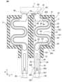
本開示の一実施形態のプローブピン10は、例えば、図1に示すように、第1方向Xに細長い薄板状で導電性を有している。このプローブピン10は、一例として、図2に示すように、絶縁性のソケット100に収容された状態で使用され、ソケット100と共に検査治具2を構成する。検査治具2には、一例として、複数のプローブピン10が収容されている。 A
また、図2に示すように、検査治具2は、検査ユニット1の一部を構成している。この実施形態では、検査ユニット1は、一対の検査治具2を有している。各検査治具2は、後述するプローブピン10の各接点部321、331、41が、ソケット100から外部に露出した状態で、第1方向Xに交差(例えば、直交)する第2方向Yに隣接するように配置されている。 Moreover, as shown in FIG. 2 , the
各ソケット100は、図2に示すように、その内部に複数の収容部101(図2には、1つのみ示す)を有している。各収容部101は、スリット状を有し、それぞれ1つのプローブピン10を電気的に独立して収容可能かつ保持可能に構成されている。また、各収容部101は、第1方向Xおよび第2方向Yに交差する方向(すなわち、図2の紙面貫通方向)に沿って一列に並んでかつ等間隔に配置されている。 Each
なお、各ソケット100は、図2に示すように、プローブピン10を収容した状態で、第1方向Xの内面とプローブピン10との間に隙間が形成されるように構成する場合に限らない。例えば、各ソケット100は、プローブピン10が、その両端の当接部201、202が共にソケット100の内面に接触した状態で収容されるように構成してもよい。 It should be noted that each
各プローブピン10は、図2に示すように、第1方向Xに沿って弾性変形可能な弾性部20と、この弾性部20の第1方向Xの両端がそれぞれ接続された第1接触部30および第2接触部40とを備えている。各プローブピン10は、一例として、電鋳法で形成され、弾性部20、第1接触部30および第2接触部40が、第1方向Xに沿って直列的に配置されかつ一体に構成されている。 Each
弾性部20は、図2に示すように、弾性部20の第1方向Xの一端を構成する第1当接部201と、弾性部20の第1方向Xの他端を構成する第2当接部202とを有している。第1当接部201は、第1接触部30から第2方向Yに延びている。第2当接部202は、第2方向Yにおいて第1当接部201と第2接触部40に対する同じ側に配置されて、第2接触部40から第2方向Yに沿って延びている。各当接部201、202は、ソケット100に収容された状態で、第1方向Xにおいて収容部101を構成するソケット100の内部に当接可能に構成されている。 As shown in FIG. 2, the
また、弾性部20は、図2に示すように、一例として、相互に隙間23を空けて配置された複数の弾性片(この実施形態では、2つの帯状の弾性片)21、22で構成されている。各弾性片21、22は、第2方向Yにそれぞれ延びた複数の延在部24と、隣接する延在部24にそれぞれ接続された複数の湾曲部25とで構成された蛇行形状を有している。この実施形態では、弾性部20は、4つの延在部24と、3つの湾曲部25とで構成されている。 In addition, as shown in FIG. 2, the
各延在部24は、第1方向Xにおいて相互に隙間27を空けて配置されている。第1方向Xの両端に配置された各延在部24が、第1当接部201および第2当接部202をそれぞれ構成している。第1当接部201を構成する延在部24は、第2方向Yの一端が第1接触部30に接続され、第2方向Yの他端が湾曲部25に接続されている。第2当接部202を構成する延在部24は、第2方向Yの一端が第2接触部40に接続され、第2方向Yの他端が湾曲部25に接続されている。なお、第2当接部202を構成する延在部24の一端は、2つの弾性片21、22が接続部26により接続されて一体化された状態で、第2接触部40に接続されている。 Each extending
各湾曲部25は、一例として、第1接触部30の第2方向Yの一端301に対して、第2方向Yの一方側に配置されている。 As an example, each
第1接触部30は、図2に示すように、一例として、弾性部20が接続された本体部31と、この本体部31から第1方向Xでかつ弾性部20から離れる方向に延びる一対の脚部32、33とを有している。 As shown in FIG. 2, the
本体部31は、第1方向Xの弾性部20側の端部に設けられた貫通孔311を有している。この貫通孔311は、弾性部20の弾性片21、22間の隙間23に接続されている。 The
各脚部32、33は、第2方向Yに隙間34を空けて配置され第2方向Yに弾性変形可能に構成されており、その先端に設けられた第1接点部321、331を有している。第1接点部321、331の各々は、接触対象物の一例である検査対象物の凸接点50に第1方向Xから接触可能に構成されている。また、各脚部32、33は、第2方向Yに対向する側面に設けられた突起部322、332を有している。各突起部322、332は、一対の脚部32、33の間の隙間34を塞ぐように突出しており、凸接点50の隙間34への過剰挿入を防止している。 Each of the
第2接触部40は、図2に示すように、一例として、第1方向Xに延びる略矩形状を有している。第2接触部40の第1方向Xでかつ弾性部20から遠い方の先端は、第1方向Xでかつ弾性部20から離れるに従って先細りとなる略三角形状を有し、第2接点部41を構成している。第2接点部41は、接触対象物の一例である検査対象物の端子60に第1方向Xから接触可能に構成されている。また、第2接触部40の第2方向Yにおいて対向する一対の側面のうちの弾性部20が接続されてない側面401には、切欠部42が設けられている。この切欠部42は、第2接触部40の側面401における第1方向Xの弾性部20に近い端に設けられている。 As an example, the
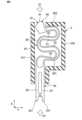
図3に、第2接触部40の第2接点部41に対して、ソケット100の内部に向かうX1方向の外力を加えた場合の弾性部20の状態を示す。図3に示すように、第2接点部41に対してX1方向の外力が加えられると、弾性部20は、隣接する弾性片21、22が接触することなく弾性変形する。また、弾性部20が、第1接触部30の第2方向Yの一端301(図2参照)に対して、あるいは、第2接触部40の第2方向Yにおいて対向する一対の側面のうちの弾性部20が接続されてない側面401(図2参照)に対して、第2方向Yにおける一方側に配置されている。このため、第2接点部41は、X1方向の外力が加えられると、端子60の表面に接触しながら、第2接触部40の側面401に対する第2方向Yにおける他方側(すなわち、第2方向Yにおいて、第2接触部40の第2方向Yの側面401から、弾性部20が配置されている側とは反対側に向かう方向)に移動する。例えば、端子60の表面上に被膜が形成されたとしても、第2接点部41のワイピング動作により、この被膜を除去することができるので、被膜の形成による接触信頼性などに対する影響を軽減できる。 FIG. 3 shows the state of the
また、図4に、X1方向の外力に加えて、第1接触部30の第1接点部321、331に対して、ソケット100の内部に向かうX2方向の外力を加えた場合の弾性部20の状態を示す。この場合においても、弾性部20は、隣接する弾性片21、22が接触することなく弾性変形し、第2接点部41によって、X1方向の外力のみが加えられた場合と同様のワイピング動作が行われる。第1接点部321、331は、X2方向の外力によって、ソケット100の内部に向かって第1方向Xに沿って移動する。 4 shows the state of the
前記プローブピン10によれば、弾性部20が、第1接触部30から第2方向Yに沿って延びて弾性部20の一端を構成する第1当接部201と、第2方向Yにおいて第1当接部201と第2接触部40に対する同じ側に配置され第2接触部40から第2方向Yに沿って延びて弾性部20の他端を構成する第2当接部202とを有する。第1当接部201および第2当接部202の各々が、ソケット100に収容されたときに第1方向Xにおいてソケット100の内部に当接可能に構成されている。このような構成により、例えば、第1接触部30および第2接触部40の各々に接点部321、331、41をそれぞれ設けたプローブピン10をソケット100に複数収容する場合、第2方向Yに隣接するプローブピン10の接点部321、331、41の配置間隔を小さくすることができる。その結果、接触対象物50、60の狭ピッチ化に対応可能なプローブピン10を実現できる。 According to the
また、第1接触部30が、第1方向Xにおける弾性部20から遠い方の端部に設けられ、接触対象物50に対して第1方向Xから接触可能な第1接点部321、331を有し、第2接触部40が、第1方向Xにおける弾性部20から遠い方の端部に設けられ、接触対象物60に対して第1方向Xから接触可能な第2接点部41を有している。このような構成により、例えば、第1接触部30および第2接触部40の各々に接点部321、331、41をそれぞれ設けたプローブピン10をソケット100に複数収容する場合、第2方向Yに隣接するプローブピン10の接点部321、331、41の配置間隔をより確実に小さくすることができる。 Further, the
また、弾性部20が、第2方向Yに沿ってそれぞれ延びると共に、第1方向Xに相互に隙間27を空けてそれぞれ配置された複数の延在部24と、隣接する延在部24に接続された湾曲部25とを有する。第1方向Xの両端に配置された延在部24の各々が、第1当接部201および第2当接部202をそれぞれ構成する。湾曲部25が、第1接触部30の第2方向Yの一端に対して、第2方向Yの一方側に配置されている。このような構成により、接触対象物50、60の狭ピッチ化に対応可能なプローブピン10を容易に実現できる。 Further, the
また、弾性部20が、相互に隙間23を空けて配置された複数の弾性片21、22を有している。このような構成により、弾性部20をより円滑に弾性変形させて、弾性部20の耐久性を向上させることができる。 Also, the
前記プローブピン10により、狭ピッチ化された検査対象物を検査可能な検査治具2を実現できる。また、前記プローブピン10を備えた検査治具2により、狭ピッチ化された検査対象物を検査可能な検査ユニット1を実現できる。 By using the probe pins 10, it is possible to realize the
なお、第1接触部30および第2接触部40の各々は、弾性部20の第1方向Xの両端がそれぞれ接続可能であれば、任意の形状および構成を採用することができる。例えば、第1接触部30および第2接触部40の各々に第2方向Yから接触対象物に接触可能な接点部を設けてもよい。また、例えば、第1接触部30に第2接点部41と同じ構成の接点部を設けてもよいし、第2接触部40に複数の接点部を設けてもよい。 Note that each of the
弾性部20は、第1当接部201および第2当接部202を有していれば、任意の形状および構成を採用することができる。例えば、弾性部20は、蛇行形状以外の形状あってもよいし、1つの弾性片で構成されていてもよい。 As long as the
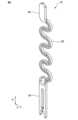
また、弾性部20は、少なくとも2つの延在部24と、少なくとも1つの湾曲部25を有していればよい。また、例えば、弾性部20は、図5~図8に示すように、図1のプローブピン10よりも多い数の延在部24および湾曲部25を有することもできる。図5~図8のプローブピン10では、弾性部20は、その第1方向Xの中間の延在部24に設けられて、一対の弾性片21、22を接続するリブ28を有している。図7および図8に示すように、このリブ28によって、第1接点部321、331および第2接点部41のいずれに対して外力が加えられたとしても、弾性部20の隣接する弾性片21、22は、接触することなく弾性変形する。なお、図7では、第1接点部321、331および第2接点部41のそれぞれに対して、X1方向およびX2方向の外力を加えた場合の弾性部20の状態を示している。 Also, the
以上、図面を参照して本開示における種々の実施形態を詳細に説明したが、最後に、本開示の種々の態様について説明する。なお、以下の説明では、一例として、参照符号も添えて記載する。 Various embodiments of the present disclosure have been described in detail above with reference to the drawings. Finally, various aspects of the present disclosure will be described. In addition, in the following description, reference numerals are also attached as an example.
本開示の第1態様のプローブピン10は、
第1方向Xに沿って弾性変形可能な弾性部20と、
前記弾性部20の前記第1方向Xの一端が接続された第1接触部30と、
前記弾性部20の前記第1方向Xの他端が接続された第2接触部40と
を備え、
前記弾性部20が、前記第1方向Xに伸縮可能な状態でソケット100に収容可能なプローブピン10であって、
前記弾性部20が、
前記第1接触部30から前記第1方向Xに交差する第2方向Yに沿って延びて前記弾性部20の前記第1方向の一端を構成する第1当接部201と、
前記第2方向Yにおいて前記第1当接部201と前記第2接触部40に対する同じ側に配置され、前記第2接触部40から前記第2方向Yに沿って延びて前記弾性部20の前記他端を構成する第2当接部202と
を有し、
前記第1当接部201および前記第2当接部202の各々が、前記ソケット100に収容された状態で前記第1方向Xにおいて前記ソケット100の内部に当接可能に構成されている。The
an
a
a
The
The
a
a
Each of the
第1態様のプローブピン10によれば、例えば、第1接触部30および第2接触部40の各々に接点部321、331、41をそれぞれ設けたプローブピン10をソケット100に複数収容する場合、第2方向Yに隣接するプローブピン10の接点部321、331、41の配置間隔を小さくすることができる。その結果、接触対象物50、60の狭ピッチ化に対応可能なプローブピン10を実現できる。 According to the
本開示の第2態様のプローブピン10は、
前記第1接触部30が、前記第1方向Xにおける前記弾性部20から遠い方の端部に設けられ、接触対象物50に対して前記第1方向Xから接触可能な第1接点部321、331を有し、
前記第2接触部40が、前記第1方向Xにおける前記弾性部20から遠い方の端部に設けられ、接触対象物60に対して前記第1方向Xから接触可能な第2接点部41を有する。The
The
The
第2態様のプローブピン10によれば、例えば、第1接触部30および第2接触部40の各々に接点部321、331、41をそれぞれ設けたプローブピン10をソケット100に複数収容する場合、第2方向Yに隣接するプローブピン10の接点部321、331、41の配置間隔をより確実に小さくすることができる。 According to the
本開示の第3態様のプローブピン10は、
前記弾性部20が、前記第1接触部30の前記第2方向Yの一端301に対して、前記第2方向Yの一方側に配置されており、
前記第1接点部321、331または前記第2接点部41の少なくともいずれかが、前記第1方向Xでかつ前記第1接点部321、331および前記第2接点部41が相互に接近する方向X1、X2の外力を加えたときに、前記第2方向Yの他方側に向かって移動可能に構成されている。The
The
At least one of the
第3態様のプローブピン10によれば、例えば、第2接点部41に対して、第1方向Xから接触対象物60を接触させて、第1接点部321、331および第2接点部41が相互に接近するX1方向の外力を加えるとする。この場合、第2接点部41は、端子60の表面に接触しながら、第2接触部40の第2方向Yの側面401に対する第2方向Yにおける他方側に移動する。このワイピング動作により、例えば、端子60の表面上に被膜が形成されたとしても、この被膜を除去することができるので、被膜の形成による接触信頼性などに対する影響を軽減できる。 According to the
本開示の第4態様のプローブピン10は、
前記弾性部20が、
前記第2方向Yに沿ってそれぞれ延びると共に、前記第1方向Xに相互に隙間27を空けてそれぞれ配置された複数の延在部24と、
隣接する前記延在部24に接続された湾曲部25と
を有し、
前記第1方向Xの両端に配置された前記延在部24の各々が、前記第1当接部201および前記第2当接部202をそれぞれ構成し、
前記湾曲部25が、前記第1接触部30の前記第2方向Yの一端301に対して、前記第2方向Yの一方側に配置されている。The
The
a plurality of extending
and a
Each of the
The
第4態様のプローブピン10によれば、接触対象物50、60の狭ピッチ化に対応可能なプローブピン10を容易に実現できる。 According to the
本開示の第5態様のプローブピン10は、
前記弾性部20が、
相互に隙間23を空けて配置された複数の弾性片21、22を有している。The
The
It has a plurality of
第5態様のプローブピン10によれば、弾性部20をより円滑に弾性変形させて、弾性部20の耐久性を向上させることができる。 According to the
本開示の第6態様の検査治具2は、
前記態様のプローブピン10と、
前記プローブピン10を収容可能な前記ソケット100と
を備え、
前記ソケット100に前記プローブピン10を収容したときに、前記第1当接部201および前記第2当接部202の各々が、前記第1方向Xにおいて、前記ソケット100の内面に当接するように構成されている。The
the
and the
Each of the
第6態様の検査治具2によれば、前記プローブピン10により、狭ピッチ化された検査対象物を検査可能な検査治具2を実現できる。 According to the
本開示の第7態様の検査ユニット1は、
前記検査治具2を少なくとも1つ備える。The
At least one
第7態様の検査ユニット1によれば、前記検査治具2により、狭ピッチ化された検査対象物を検査可能な検査ユニット1を実現できる。 According to the
なお、前記様々な実施形態または変形例のうちの任意の実施形態または変形例を適宜組み合わせることにより、それぞれの有する効果を奏するようにすることができる。また、実施形態同士の組み合わせまたは実施例同士の組み合わせまたは実施形態と実施例との組み合わせが可能であると共に、異なる実施形態または実施例の中の特徴同士の組み合わせも可能である。 By appropriately combining any of the various embodiments or modifications described above, the respective effects can be obtained. In addition, combinations of embodiments, combinations of examples, or combinations of embodiments and examples are possible, as well as combinations of features in different embodiments or examples.
本開示のプローブピンは、例えば、カメラデバイス、USBデバイス、HDMI(登録商標)デバイス、あるいは、QFNデバイスおよびSONデバイスなどの半導体の検査に用いる検査治具に適用できる。 The probe pin of the present disclosure can be applied to, for example, camera devices, USB devices, HDMI (registered trademark) devices, or inspection jigs used for inspection of semiconductors such as QFN devices and SON devices.
本開示の検査治具は、例えば、カメラデバイス、USBデバイス、HDMI(登録商標)デバイス、あるいは、QFNデバイスおよびSONデバイスなどの半導体の検査に用いる検査ユニットに適用できる。 The inspection jig of the present disclosure can be applied, for example, to an inspection unit used for inspection of semiconductors such as camera devices, USB devices, HDMI (registered trademark) devices, or QFN devices and SON devices.
本開示の検査ユニットは、例えば、カメラデバイス、USBデバイス、HDMI(登録商標)デバイス、あるいは、QFNデバイスおよびSONデバイスなどの半導体の検査に用いることができる。 The inspection unit of the present disclosure can be used, for example, to inspect camera devices, USB devices, HDMI® devices, or semiconductors such as QFN and SON devices.
1 検査ユニット
2 検査治具
10 プローブピン
20 弾性部
201 第1当接部
202 第2当接部
21、22 弾性片
23 隙間
24 延在部
25 湾曲部
26 接続部
27 隙間
28 リブ
30 第1接触部
301 一端
31 本体部
311 貫通孔
32、33 脚部
321、331 第1接点部
322、332 突起部
34 隙間
40 第2接触部
401 側面
41 第2接点部
42 切欠部
50 凸接点
60 端子
100 ソケット
101 収容部1
Claims (8)
Translated fromJapanese前記弾性部の前記第1方向の一端が接続された第1接触部と、
前記弾性部の前記第1方向の他端が接続された第2接触部と
を備え、
前記弾性部が、前記第1方向に伸縮可能な状態でソケットに収容可能なプローブピンであって、
前記弾性部が、
前記第1接触部から前記第1方向に交差する第2方向に沿って延びて前記弾性部の前記第1方向の一端を構成する第1当接部と、
前記第2方向において前記第1当接部と前記第2接触部に対する同じ側に配置され、前記第2接触部から前記第2方向に沿って延びて前記弾性部の前記他端を構成する第2当接部と
を有し、
前記第1当接部および前記第2当接部の各々が、前記ソケットに収容された状態で前記第1方向において前記ソケットの内部に当接可能に構成され、
前記弾性部が、
相互に隙間を空けて配置された複数の弾性片で構成されていると共に、
前記プローブピンが前記ソケットに収容され前記第1当接部が前記ソケットの内部に接触した状態で前記第2接触部から前記ソケットの内部に向かう方向に外力を加えた場合、または、前記プローブピンが前記ソケットに収容され前記第2当接部が前記ソケットの内部に接触した状態で前記第1接触部から前記ソケットの内部に向かう方向に外力を加えた場合に、隣接する前記弾性片が接触することなく弾性変形するように構成されている、プローブピン。an elastic portion elastically deformable along a first direction;
a first contact portion connected to one end of the elastic portion in the first direction;
a second contact portion to which the other end of the elastic portion in the first direction is connected;
A probe pin that can be accommodated in a socket in a state in which the elastic portion can expand and contract in the first direction,
The elastic portion is
a first contact portion extending from the first contact portion along a second direction intersecting the first direction and forming one end of the elastic portion in the first direction;
a second contact portion disposed on the same side with respect to the first contact portion and the second contact portion in the second direction and extending from the second contact portion along the second direction to constitute the other end of the elastic portion;
each of the first contact portion and the second contact portion is configured to contact the inside of the socket in the first direction while being housed in the socket;
The elastic portion is
It is composed of a plurality of elastic pieces arranged with a gap between them, and
When an external force is applied in a direction from the second contact portion toward the inside of the socket while the probe pin is accommodated in the socket and the first contact portion is in contact with the inside of the socket, or when an external force is applied in a direction from the first contact portion toward the inside of the socket while the probe pin is accommodated in the socket and the second contact portion is in contact with the inside of the socket, the adjacent elastic pieces are configured to elastically deform without coming into contact with each other.
前記弾性部が、前記第1接触部の前記第2方向の一端に対して、または、前記第2接触部の前記一対の側面のうちの前記弾性部が接続されていない側面に対して、前記第2方向における一方側に配置されている、請求項1のプローブピン。The elastic portion is arranged on one side in the second direction with respect to one end of the first contact portion in the second direction, or one of the pair of side surfaces of the second contact portion to which the elastic portion is not connected.
前記第2接触部が、前記第1方向における前記弾性部から遠い方の端部に設けられ、接触対象物に対して前記第1方向から接触可能な第2接点部を有する、請求項1または2のプローブピン。The first contact portion has a first contact portion provided at an end farther from the elastic portion in the first direction and capable of contacting a contact object from the first direction,
3. The probe pin according to claim 1,wherein said second contact portion has a second contact portion provided at an end portion in said first direction farther from said elastic portion and capable of contacting a contact object from said first direction.
前記第1接点部または前記第2接点部の少なくともいずれかが、前記第1方向でかつ前記第1接点部および前記第2接点部が相互に接近する方向の外力を加えたときに、前記第2方向の他方側に向かって移動可能に構成されている、請求項3のプローブピン。The elastic portion is arranged on one side in the second direction with respect to one end of the first contact portion in the second direction,
When at least one of the first contact portion and the second contact portion is applied with an external force in the first direction and in a direction in which the first contact portion and the second contact portion approach each other, the probe pin of claim3 , which is configured to be movable toward the other side in the second direction.
前記第2方向に沿ってそれぞれ延びると共に、前記第1方向に相互に隙間を空けてそれぞれ配置された複数の延在部と、
隣接する前記延在部に接続された湾曲部と
を有し、
前記第1方向の両端に配置された前記延在部の各々が、前記第1当接部および前記第2当接部をそれぞれ構成し、
前記湾曲部が、前記第1接触部の前記第2方向の一端に対して、前記第2方向の一方側に配置されている、請求項1から4のいずれか1つのプローブピン。The elastic portion is
a plurality of extending portions each extending along the second direction and arranged with a gap between each other in the first direction;
a curved portion connected to the adjacent extension;
each of the extension portions arranged at both ends in the first direction constitutes the first contact portion and the second contact portion, respectively;
The probe pin according to any one of claims 1 to4 , wherein the curved portion is arranged on one side in the second direction with respect to one end of the first contact portion in the second direction.
相互に隙間を空けて配置された複数の弾性片を有している、請求項1から5のいずれか1つのプローブピン。The elastic portion is
6. A probe pin according to any one of claims 1 to5 , having a plurality of elastic pieces spaced apart from each other.
前記プローブピンを収容可能な前記ソケットと
を備え、
前記ソケットに前記プローブピンを収容したときに、前記第1当接部および前記第2当接部の各々が、前記第1方向において、前記ソケットの内面に当接するように構成されている、検査治具。A probe pin according to any one of claims 1 to6 ;
and the socket capable of accommodating the probe pin,
An inspection jig, wherein each of the first contact portion and the second contact portion is configured to contact an inner surface of the socket in the first direction when the probe pin is accommodated in the socket.
Priority Applications (6)
| Application Number | Priority Date | Filing Date | Title |
|---|---|---|---|
| JP2019108955AJP7314633B2 (en) | 2019-06-11 | 2019-06-11 | Probe pins, inspection fixtures and inspection units |
| CN201921274242.4UCN210690650U (en) | 2018-11-08 | 2019-08-07 | Probe, inspection jig, and inspection unit |
| CN202080040779.3ACN113924499A (en) | 2019-06-11 | 2020-05-21 | Probe, inspection tool, and inspection unit |
| PCT/JP2020/020160WO2020250637A1 (en) | 2019-06-11 | 2020-05-21 | Probe pin, testing jig, and testing unit |
| KR1020217039154AKR102710367B1 (en) | 2019-06-11 | 2020-05-21 | Probe pins, inspection jigs and inspection units |
| TW109118271ATWI743817B (en) | 2019-06-11 | 2020-06-01 | Probe, inspection jig and inspection unit |
Applications Claiming Priority (1)
| Application Number | Priority Date | Filing Date | Title |
|---|---|---|---|
| JP2019108955AJP7314633B2 (en) | 2019-06-11 | 2019-06-11 | Probe pins, inspection fixtures and inspection units |
Publications (2)
| Publication Number | Publication Date |
|---|---|
| JP2020201161A JP2020201161A (en) | 2020-12-17 |
| JP7314633B2true JP7314633B2 (en) | 2023-07-26 |
Family
ID=73742021
Family Applications (1)
| Application Number | Title | Priority Date | Filing Date |
|---|---|---|---|
| JP2019108955AActiveJP7314633B2 (en) | 2018-11-08 | 2019-06-11 | Probe pins, inspection fixtures and inspection units |
Country Status (5)
| Country | Link |
|---|---|
| JP (1) | JP7314633B2 (en) |
| KR (1) | KR102710367B1 (en) |
| CN (1) | CN113924499A (en) |
| TW (1) | TWI743817B (en) |
| WO (1) | WO2020250637A1 (en) |
Families Citing this family (6)
| Publication number | Priority date | Publication date | Assignee | Title |
|---|---|---|---|---|
| TWI745182B (en)* | 2020-11-30 | 2021-11-01 | 中華精測科技股份有限公司 | Probe card device and dual-arm probe |
| JP7647177B2 (en)* | 2021-03-04 | 2025-03-18 | オムロン株式会社 | Probe pins, inspection jigs and inspection jig units |
| WO2022249954A1 (en)* | 2021-05-28 | 2022-12-01 | 株式会社日本マイクロニクス | Probe |
| CN115436675A (en)* | 2021-06-04 | 2022-12-06 | 迪科特测试科技(苏州)有限公司 | Testing device and probe assembly thereof |
| KR102823858B1 (en) | 2022-04-05 | 2025-06-23 | 주식회사 오킨스전자 | Contact pins for test sockets and test sockets comprising the same |
| TWI859778B (en)* | 2023-03-20 | 2024-10-21 | 吳俊杰 | Test probes and detection devices |
Citations (7)
| Publication number | Priority date | Publication date | Assignee | Title |
|---|---|---|---|---|
| JP2002134202A (en) | 2000-10-27 | 2002-05-10 | Otax Co Ltd | Receptacle for electronic parts |
| JP2006226907A (en) | 2005-02-18 | 2006-08-31 | Nhk Spring Co Ltd | Conductive contact unit and conductive contact |
| WO2014167693A1 (en) | 2013-04-11 | 2014-10-16 | ルネサスエレクトロニクス株式会社 | Production method for semiconductor device |
| WO2016156002A1 (en) | 2015-03-31 | 2016-10-06 | Technoprobe S.P.A. | Contact probe and corresponding testing head with vertical probes, particularly for high frequency applications |
| CN107038983A (en) | 2016-02-03 | 2017-08-11 | 普罗-2000有限公司 | Pin type plugboard |
| JP2017223628A (en) | 2016-06-17 | 2017-12-21 | オムロン株式会社 | Probe pin |
| KR101851519B1 (en) | 2017-12-14 | 2018-04-23 | 오므론 가부시키가이샤 | Socket, inspection jig, inspection unit and inspection apparatus |
Family Cites Families (10)
| Publication number | Priority date | Publication date | Assignee | Title |
|---|---|---|---|---|
| JP3762444B2 (en)* | 1993-08-24 | 2006-04-05 | 信昭 鈴木 | Circuit board inspection probe and its mounting structure |
| JP4907191B2 (en)* | 2006-02-17 | 2012-03-28 | 日本発條株式会社 | Conductive contact unit |
| CN107026337B (en)* | 2016-02-01 | 2020-09-08 | 富士康(昆山)电脑接插件有限公司 | Electric connector and conductive terminal thereof |
| JP6627655B2 (en)* | 2016-06-17 | 2020-01-08 | オムロン株式会社 | socket |
| WO2018003507A1 (en)* | 2016-06-28 | 2018-01-04 | 株式会社日本マイクロニクス | Electrical connecting device and contact |
| CN108110450A (en)* | 2016-11-24 | 2018-06-01 | 泰科电子(上海)有限公司 | Terminal and connector |
| CN206975085U (en)* | 2017-08-04 | 2018-02-06 | 健坤精密科技(深圳)有限公司 | A kind of precision measurement probe |
| WO2019138504A1 (en) | 2018-01-11 | 2019-07-18 | オムロン株式会社 | Probe pin, test jig, test unit, and test device |
| CN111033272B (en) | 2018-01-11 | 2022-07-26 | 欧姆龙株式会社 | Probe, inspection tool, inspection unit, and inspection device |
| CN108572264B (en)* | 2018-06-21 | 2023-12-01 | 武汉精测电子集团股份有限公司 | Crimping shell fragment of single buffering passageway |
- 2019
- 2019-06-11JPJP2019108955Apatent/JP7314633B2/enactiveActive
- 2020
- 2020-05-21CNCN202080040779.3Apatent/CN113924499A/enactivePending
- 2020-05-21KRKR1020217039154Apatent/KR102710367B1/enactiveActive
- 2020-05-21WOPCT/JP2020/020160patent/WO2020250637A1/ennot_activeCeased
- 2020-06-01TWTW109118271Apatent/TWI743817B/enactive
Patent Citations (7)
| Publication number | Priority date | Publication date | Assignee | Title |
|---|---|---|---|---|
| JP2002134202A (en) | 2000-10-27 | 2002-05-10 | Otax Co Ltd | Receptacle for electronic parts |
| JP2006226907A (en) | 2005-02-18 | 2006-08-31 | Nhk Spring Co Ltd | Conductive contact unit and conductive contact |
| WO2014167693A1 (en) | 2013-04-11 | 2014-10-16 | ルネサスエレクトロニクス株式会社 | Production method for semiconductor device |
| WO2016156002A1 (en) | 2015-03-31 | 2016-10-06 | Technoprobe S.P.A. | Contact probe and corresponding testing head with vertical probes, particularly for high frequency applications |
| CN107038983A (en) | 2016-02-03 | 2017-08-11 | 普罗-2000有限公司 | Pin type plugboard |
| JP2017223628A (en) | 2016-06-17 | 2017-12-21 | オムロン株式会社 | Probe pin |
| KR101851519B1 (en) | 2017-12-14 | 2018-04-23 | 오므론 가부시키가이샤 | Socket, inspection jig, inspection unit and inspection apparatus |
Also Published As
| Publication number | Publication date |
|---|---|
| KR102710367B1 (en) | 2024-09-27 |
| JP2020201161A (en) | 2020-12-17 |
| KR20220003591A (en) | 2022-01-10 |
| TW202045933A (en) | 2020-12-16 |
| TWI743817B (en) | 2021-10-21 |
| WO2020250637A1 (en) | 2020-12-17 |
| CN113924499A (en) | 2022-01-11 |
Similar Documents
| Publication | Publication Date | Title |
|---|---|---|
| JP7314633B2 (en) | Probe pins, inspection fixtures and inspection units | |
| CN111033272B (en) | Probe, inspection tool, inspection unit, and inspection device | |
| KR101911005B1 (en) | Probe pin, inspection jig, inspection unit and inspection apparatus | |
| JP6515877B2 (en) | Probe pin | |
| JP7306082B2 (en) | Probe pins, inspection fixtures and inspection units | |
| WO2017217042A1 (en) | Probe pin | |
| JP7354534B2 (en) | Probe pins and inspection fixtures | |
| JP7620385B2 (en) | Probe pins, inspection jigs and inspection units | |
| WO2018055961A1 (en) | Probe pin and inspection unit | |
| JP7636685B2 (en) | Probe pins, inspection jigs and inspection units | |
| JP6583582B2 (en) | Probe pin | |
| JP2020091298A (en) | Probe pin, inspection jig, inspection unit, and inspection device | |
| JP2019191196A (en) | Probe pin | |
| JP2022135106A (en) | Probe pins, test fixtures and test fixture units | |
| CN210690650U (en) | Probe, inspection jig, and inspection unit | |
| JP2019207245A (en) | Probe pin | |
| JP6881354B2 (en) | Inspection unit and inspection equipment | |
| JP2020076664A (en) | Probe pin, inspection jig, inspection unit, and inspection device |
Legal Events
| Date | Code | Title | Description |
|---|---|---|---|
| A621 | Written request for application examination | Free format text:JAPANESE INTERMEDIATE CODE: A621 Effective date:20220407 | |
| A131 | Notification of reasons for refusal | Free format text:JAPANESE INTERMEDIATE CODE: A131 Effective date:20230124 | |
| A521 | Request for written amendment filed | Free format text:JAPANESE INTERMEDIATE CODE: A523 Effective date:20230324 | |
| TRDD | Decision of grant or rejection written | ||
| A01 | Written decision to grant a patent or to grant a registration (utility model) | Free format text:JAPANESE INTERMEDIATE CODE: A01 Effective date:20230613 | |
| A61 | First payment of annual fees (during grant procedure) | Free format text:JAPANESE INTERMEDIATE CODE: A61 Effective date:20230626 | |
| R150 | Certificate of patent or registration of utility model | Ref document number:7314633 Country of ref document:JP Free format text:JAPANESE INTERMEDIATE CODE: R150 |