JP7310661B2 - Terminals and wires with terminals - Google Patents
Terminals and wires with terminalsDownload PDFInfo
- Publication number
- JP7310661B2 JP7310661B2JP2020043008AJP2020043008AJP7310661B2JP 7310661 B2JP7310661 B2JP 7310661B2JP 2020043008 AJP2020043008 AJP 2020043008AJP 2020043008 AJP2020043008 AJP 2020043008AJP 7310661 B2JP7310661 B2JP 7310661B2
- Authority
- JP
- Japan
- Prior art keywords
- upper wall
- terminal
- wall
- slide
- contact
- Prior art date
- Legal status (The legal status is an assumption and is not a legal conclusion. Google has not performed a legal analysis and makes no representation as to the accuracy of the status listed.)
- Active
Links
- 238000003825pressingMethods0.000claimsdescription29
- 238000005452bendingMethods0.000claimsdescription7
- 229910052751metalInorganic materials0.000description21
- 239000002184metalSubstances0.000description21
- 238000000034methodMethods0.000description7
- 230000013011matingEffects0.000description6
- RYGMFSIKBFXOCR-UHFFFAOYSA-NCopperChemical compound[Cu]RYGMFSIKBFXOCR-UHFFFAOYSA-N0.000description5
- 229910000881Cu alloyInorganic materials0.000description5
- 229910052802copperInorganic materials0.000description5
- 239000010949copperSubstances0.000description5
- 238000002788crimpingMethods0.000description5
- PXHVJJICTQNCMI-UHFFFAOYSA-NNickelChemical compound[Ni]PXHVJJICTQNCMI-UHFFFAOYSA-N0.000description4
- 229910000838Al alloyInorganic materials0.000description3
- ATJFFYVFTNAWJD-UHFFFAOYSA-NTinChemical compound[Sn]ATJFFYVFTNAWJD-UHFFFAOYSA-N0.000description3
- 229910052782aluminiumInorganic materials0.000description3
- XAGFODPZIPBFFR-UHFFFAOYSA-NaluminiumChemical compound[Al]XAGFODPZIPBFFR-UHFFFAOYSA-N0.000description3
- 239000011248coating agentSubstances0.000description3
- 238000000576coating methodMethods0.000description3
- 239000000463materialSubstances0.000description3
- 238000007747platingMethods0.000description3
- 239000010935stainless steelSubstances0.000description3
- 229910001220stainless steelInorganic materials0.000description3
- 229910052718tinInorganic materials0.000description3
- BQCADISMDOOEFD-UHFFFAOYSA-NSilverChemical compound[Ag]BQCADISMDOOEFD-UHFFFAOYSA-N0.000description2
- 230000000694effectsEffects0.000description2
- 229910052759nickelInorganic materials0.000description2
- 229910052709silverInorganic materials0.000description2
- 239000004332silverSubstances0.000description2
- 239000011135tinSubstances0.000description2
- 238000005266castingMethods0.000description1
- 239000000470constituentSubstances0.000description1
- 238000005520cutting processMethods0.000description1
- 238000009413insulationMethods0.000description1
- 238000004519manufacturing processMethods0.000description1
- 238000012986modificationMethods0.000description1
- 230000004048modificationEffects0.000description1
- 229920003002synthetic resinPolymers0.000description1
- 239000000057synthetic resinSubstances0.000description1
Images


Classifications
- H—ELECTRICITY
- H01—ELECTRIC ELEMENTS
- H01R—ELECTRICALLY-CONDUCTIVE CONNECTIONS; STRUCTURAL ASSOCIATIONS OF A PLURALITY OF MUTUALLY-INSULATED ELECTRICAL CONNECTING ELEMENTS; COUPLING DEVICES; CURRENT COLLECTORS
- H01R4/00—Electrically-conductive connections between two or more conductive members in direct contact, i.e. touching one another; Means for effecting or maintaining such contact; Electrically-conductive connections having two or more spaced connecting locations for conductors and using contact members penetrating insulation
- H01R4/28—Clamped connections, spring connections
- H01R4/50—Clamped connections, spring connections utilising a cam, wedge, cone or ball also combined with a screw
- H01R4/5083—Clamped connections, spring connections utilising a cam, wedge, cone or ball also combined with a screw using a wedge
- H—ELECTRICITY
- H01—ELECTRIC ELEMENTS
- H01R—ELECTRICALLY-CONDUCTIVE CONNECTIONS; STRUCTURAL ASSOCIATIONS OF A PLURALITY OF MUTUALLY-INSULATED ELECTRICAL CONNECTING ELEMENTS; COUPLING DEVICES; CURRENT COLLECTORS
- H01R4/00—Electrically-conductive connections between two or more conductive members in direct contact, i.e. touching one another; Means for effecting or maintaining such contact; Electrically-conductive connections having two or more spaced connecting locations for conductors and using contact members penetrating insulation
- H01R4/10—Electrically-conductive connections between two or more conductive members in direct contact, i.e. touching one another; Means for effecting or maintaining such contact; Electrically-conductive connections having two or more spaced connecting locations for conductors and using contact members penetrating insulation effected solely by twisting, wrapping, bending, crimping, or other permanent deformation
- H01R4/18—Electrically-conductive connections between two or more conductive members in direct contact, i.e. touching one another; Means for effecting or maintaining such contact; Electrically-conductive connections having two or more spaced connecting locations for conductors and using contact members penetrating insulation effected solely by twisting, wrapping, bending, crimping, or other permanent deformation by crimping
- H01R4/183—Electrically-conductive connections between two or more conductive members in direct contact, i.e. touching one another; Means for effecting or maintaining such contact; Electrically-conductive connections having two or more spaced connecting locations for conductors and using contact members penetrating insulation effected solely by twisting, wrapping, bending, crimping, or other permanent deformation by crimping for cylindrical elongated bodies, e.g. cables having circular cross-section
- H—ELECTRICITY
- H01—ELECTRIC ELEMENTS
- H01R—ELECTRICALLY-CONDUCTIVE CONNECTIONS; STRUCTURAL ASSOCIATIONS OF A PLURALITY OF MUTUALLY-INSULATED ELECTRICAL CONNECTING ELEMENTS; COUPLING DEVICES; CURRENT COLLECTORS
- H01R11/00—Individual connecting elements providing two or more spaced connecting locations for conductive members which are, or may be, thereby interconnected, e.g. end pieces for wires or cables supported by the wire or cable and having means for facilitating electrical connection to some other wire, terminal, or conductive member, blocks of binding posts
- H01R11/11—End pieces or tapping pieces for wires, supported by the wire and for facilitating electrical connection to some other wire, terminal or conductive member
- H—ELECTRICITY
- H01—ELECTRIC ELEMENTS
- H01R—ELECTRICALLY-CONDUCTIVE CONNECTIONS; STRUCTURAL ASSOCIATIONS OF A PLURALITY OF MUTUALLY-INSULATED ELECTRICAL CONNECTING ELEMENTS; COUPLING DEVICES; CURRENT COLLECTORS
- H01R4/00—Electrically-conductive connections between two or more conductive members in direct contact, i.e. touching one another; Means for effecting or maintaining such contact; Electrically-conductive connections having two or more spaced connecting locations for conductors and using contact members penetrating insulation
- H01R4/26—Connections in which at least one of the connecting parts has projections which bite into or engage the other connecting part in order to improve the contact
Landscapes
- Connections Effected By Soldering, Adhesion, Or Permanent Deformation (AREA)
Description
Translated fromJapanese本開示は、端子、および端子付き電線に関する。 TECHNICAL FIELD The present disclosure relates to terminals and electric wires with terminals.
従来、電線の端末から露出する芯線に端子が接続された端子付き電線が知られている。このような端子として、例えば、電線の端末から露出する芯線に外側から圧着する圧着部を備えるものがある。 2. Description of the Related Art Conventionally, an electric wire with a terminal is known in which a terminal is connected to a core wire exposed from an end of the electric wire. As such a terminal, for example, there is a terminal provided with a crimp portion that is crimped from the outside to a core wire exposed from an end of an electric wire.
上記の端子を電線に圧着するには、例えば以下のようにする。まず、金属板材をプレス加工することにより所定の形状の端子を成形する。続いて、上下方向に相対移動可能な一対の金型のうち下側に位置する下型の載置部に、端子を載置する。続いて、電線の端末から露出された芯線を、端子の圧着部に重ねて載置する。その後、一対の金型の一方又は双方を互いに接近する方向に移動させ、上型の圧着部と、下型の載置部との間で圧着部を挟み付けることにより、圧着部を電線の芯線に圧着する。以上により、電線の端末に端子が接続される(特許文献1参照)。 For crimping the terminal to the electric wire, for example, the following procedure is performed. First, a terminal having a predetermined shape is formed by pressing a metal plate material. Subsequently, the terminal is placed on the placement portion of the lower mold positioned on the lower side of the pair of molds that are relatively movable in the vertical direction. Subsequently, the core wire exposed from the end of the electric wire is laid on the crimping portion of the terminal. After that, one or both of the pair of molds are moved in a direction toward each other, and the crimping portion is sandwiched between the crimping portion of the upper mold and the mounting portion of the lower mold, thereby forming the core wire of the electric wire. crimp to. As described above, the terminal is connected to the end of the electric wire (see Patent Document 1).
上記の圧着部に代えて、芯線を挟んで接続するとした場合、端子本体と、端子本体の後方に配されたスライド部との2部品で端子を構成することがあり得る。この場合、スライド部を押圧してスライドさせる際に、スライド部に加えられた力によってスライド部が変形する等の不具合が生じることが懸念される。 If the core wire is sandwiched for connection instead of the crimping portion, the terminal may be composed of two parts, a terminal main body and a sliding portion arranged behind the terminal main body. In this case, when the slide portion is pushed and slid, there is a concern that the force applied to the slide portion may deform the slide portion.
本開示は上記のような事情に基づいて完成されたものであって、スライド部の強度が向上された端子を提供することを目的とする。 The present disclosure has been completed based on the circumstances as described above, and an object of the present disclosure is to provide a terminal in which the strength of the sliding portion is improved.
本開示は、電線の前端部に接続される端子であって、端子本体と、スライド部と、を備え、前記端子本体は前記電線を挟持する挟持部を有し、前記スライド部は、前記端子本体に外嵌する筒状をなしており、前記スライド部は、前記スライド部の内面から内方に突出する加圧部を有し、前記スライド部は、前記端子本体に対して、前記加圧部が前記挟持部と接触しない非接触位置と、前記非接触位置よりも前方の接触位置であって前記加圧部が前記挟持部に接触する前記接触位置と、の間でスライド可能に配されており、前記スライド部は、下壁と、前記下壁の一方の側縁から上方に延びる第1側壁と、前記下壁の他方の側縁から上方に延びる第2側壁と、を有し、前記第1側壁の上端部には、折れ曲がった第1折れ曲がり部を介して前記第2側壁に向かって延びる第1上壁が形成されており、前記第2側壁の上端部には、前記第1上壁よりも前方の位置に、折れ曲がった第2折れ曲がり部を介して前記第1側壁に向かって延びる第2上壁が形成されており、前記第1上壁には外方に突出する突出部が形成されており、前記第2上壁の後端縁または前記第2折れ曲がり部の後端縁には、前記第1上壁の前記突出部が後方から押圧された力を受ける後保持部が設けられている。 The present disclosure is a terminal connected to a front end portion of an electric wire, comprising a terminal body and a slide portion, the terminal body having a clamping portion that clamps the electric wire, the slide portion being connected to the terminal. The terminal body has a cylindrical shape fitted to the main body, and the sliding portion has a pressing portion protruding inward from the inner surface of the sliding portion, and the sliding portion applies the pressure to the terminal body. and the contact position forward of the non-contact position and the contact position where the pressurizing portion contacts the holding portion. the slide portion has a lower wall, a first side wall extending upward from one side edge of the lower wall, and a second side wall extending upward from the other side edge of the lower wall; A first upper wall extending toward the second side wall via a first bent portion is formed at the upper end of the first side wall, and the first upper wall is formed at the upper end of the second side wall. A second upper wall extending toward the first side wall via a second bent portion is formed at a position forward of the upper wall, and the first upper wall protrudes outwardly. is formed on the rear end edge of the second upper wall or the rear end edge of the second bent portion, a rear holding portion that receives the force of the projecting portion of the first upper wall being pressed from the rear. is provided.
本開示によれば、スライド部の強度を向上させることができる。 According to the present disclosure, it is possible to improve the strength of the slide portion.
[本開示の実施形態の説明]
最初に本開示の実施態様を列挙して説明する。[Description of Embodiments of the Present Disclosure]
First, embodiments of the present disclosure are enumerated and described.
(1)本開示は、電線の前端部に接続される端子であって、端子本体と、スライド部と、を備え、前記端子本体は前記電線を挟持する挟持部を有し、前記スライド部は、前記端子本体に外嵌する筒状をなしており、前記スライド部は、前記スライド部の内面から内方に突出する加圧部を有し、前記スライド部は、前記端子本体に対して、前記加圧部が前記挟持部と接触しない非接触位置と、前記非接触位置よりも前方の接触位置であって前記加圧部が前記挟持部に接触する前記接触位置と、の間でスライド可能に配されており、前記スライド部は、下壁と、前記下壁の一方の側縁から上方に延びる第1側壁と、前記下壁の他方の側縁から上方に延びる第2側壁と、を有し、前記第1側壁の上端部には、折れ曲がった第1折れ曲がり部を介して前記第2側壁に向かって延びる第1上壁が形成されており、前記第2側壁の上端部には、前記第1上壁よりも前方の位置に、折れ曲がった第2折れ曲がり部を介して前記第1側壁に向かって延びる第2上壁が形成されており、前記第1上壁には外方に突出する突出部が形成されており、前記第2上壁の後端縁または前記第2折れ曲がり部の後端縁には、前記第1上壁の前記突出部が後方から押圧された力を受ける後保持部が設けられている。(1) The present disclosure is a terminal connected to a front end portion of an electric wire, comprising a terminal body and a slide portion, the terminal body having a clamping portion that clamps the electric wire, the slide portion , the terminal body has a cylindrical shape to be fitted onto the terminal body, the slide section has a pressurizing section protruding inward from the inner surface of the slide section, and the slide section presses against the terminal body to: The pressurizing part is slidable between a non-contact position where the pressurizing part does not contact the clamping part, and a contact position forward of the non-contact position and the contact position where the pressurizing part contacts the clamping part. The slide portion includes a lower wall, a first side wall extending upward from one side edge of the lower wall, and a second side wall extending upward from the other side edge of the lower wall. and a first upper wall extending toward the second side wall through a first bent portion is formed at the upper end of the first side wall, and the upper end of the second side wall includes: A second upper wall extending toward the first side wall via a second bent portion is formed at a position forward of the first upper wall, and protrudes outward from the first upper wall. The rear end edge of the second upper wall or the rear end edge of the second bent portion receives a force pressing the protrusion of the first upper wall from the rear. A retainer is provided.
治具によって突出部が前方に押圧されると、突出部が設けられた第1上壁が前方に押圧される。すると、治具が突出部を前方に押圧する際に第1上壁に加えられた力は、第2上壁の後保持部によって受けられる。これによりスライド部の強度を向上させることができる。 When the protrusion is pressed forward by the jig, the first upper wall provided with the protrusion is pressed forward. Then, the force applied to the first upper wall when the jig pushes the projecting portion forward is received by the rear holding portion of the second upper wall. Thereby, the strength of the sliding portion can be improved.
(2)前記後保持部は前記第2折れ曲がり部の後端縁を含み、前記第1上壁の前端縁のうち前記第2側壁側の端部は、前記第1上壁の前記突出部が後方から押圧されたときに、前記第2折れ曲がり部の後端縁と接触する第1接触部とされることが好ましい。(2) The rear holding portion includes the rear edge of the second bent portion, and the end of the front edge of the first upper wall on the side of the second side wall corresponds to the projecting portion of the first upper wall. It is preferable that the first contact portion is in contact with the rear edge of the second bent portion when pressed from behind.
治具によって突出部が後方から前方に押圧されると、第1上壁は、上方から見て、第1折れ曲がり部の後端部が支点のように機能することにより、回転するように動く。これにより、第1上壁の前端縁のうち第2側壁側に形成された第1接触部は、第2上壁の後保持部に後方から当接する。第2折れ曲がり部は折れ曲がっているので、第2折れ曲がり部の強度は、第2側壁および第2上壁よりも大きくなっている。これによりスライド部の強度を向上させることができる。 When the protrusion is pressed forward from the rear by the jig, the first upper wall rotates as viewed from above because the rear end of the first bent portion functions as a fulcrum. As a result, the first contact portion formed on the second side wall side of the front edge of the first upper wall contacts the rear holding portion of the second upper wall from behind. Since the second bent portion is bent, the strength of the second bent portion is greater than that of the second side wall and the second upper wall. Thereby, the strength of the sliding portion can be improved.
(3)前記第1側壁の上端縁には、前記第1折れ曲がり部よりも前方の位置に、上方に突出する前保持部が形成されており、前記第2上壁には、前記前保持部の後方に、第2接触部が設けられており、前記第2上壁の後保持部に加えられた力は、前記第2接触部が前記前保持部に後方から当接することによって受けられることが好ましい。(3) A front holding portion projecting upward is formed at a position forward of the first bent portion on the upper edge of the first side wall, and the front holding portion is formed on the second upper wall. A second contact portion is provided behind the second upper wall, and the force applied to the rear holding portion of the second upper wall is received by the second contact portion coming into contact with the front holding portion from the rear. is preferred.
後保持部に後方から力が加えられると、第2上壁は、上方から見て、第2折れ曲がり部の後端部が支点のように機能することにより、回転するように動く。これにより、第2上壁のうち第2側壁側に形成された第2接触部は、第1上壁の前保持部に後方から当接する。これにより第2接触部が受けた力が前保持部によって受けられるので、スライド部の強度を向上させることができる。 When a force is applied to the rear holding portion from behind, the second upper wall rotates as viewed from above as the rear end portion of the second bent portion functions as a fulcrum. As a result, the second contact portion formed on the second side wall side of the second upper wall contacts the front holding portion of the first upper wall from behind. As a result, the force received by the second contact portion is received by the front holding portion, so that the strength of the slide portion can be improved.
(4)前記突出部は、前記第1折れ曲がり部の近傍に形成されていることが好ましい。(4) It is preferable that the protruding portion is formed in the vicinity of the first bent portion.
治具によって突出部が後方から前方に押圧されると、第1上壁は、上方から見て、第1折れ曲がり部の後端部が支点のように機能することにより、回転するように動く。突出部は、支点のように機能する第1折れ曲がり部の近傍に形成されているので、突出部が後方から押圧されたときに、第1上壁が回転しにくくなっている。これにより、スライド部の強度を向上させることができる。 When the protrusion is pressed forward from the rear by the jig, the first upper wall rotates as viewed from above because the rear end of the first bent portion functions as a fulcrum. Since the projecting portion is formed near the first bent portion that functions like a fulcrum, the first upper wall is less likely to rotate when the projecting portion is pressed from behind. Thereby, the strength of the sliding portion can be improved.
(5)前記突出部は、前記第1上壁が曲げられて形成されていることが好ましい。(5) It is preferable that the protrusion is formed by bending the first upper wall.
突出部は、第1上壁が曲げられることにより形成されているので、突出部を構成する金属板材の厚さが、他の部分よりも薄くなる部分が形成されにくい。これにより、突出部の強度を向上させることができるので、スライド部の強度を向上させることができる。 Since the protruding portion is formed by bending the first upper wall, it is difficult to form a portion where the thickness of the metal plate material forming the protruding portion is thinner than other portions. As a result, the strength of the projecting portion can be improved, so that the strength of the sliding portion can be improved.
(6)前記スライド部は、前記第1上壁の後方に第3上壁を有し、前記加圧部が前記第3上壁に設けられていることが好ましい。(6) It is preferable that the sliding portion has a third upper wall behind the first upper wall, and the pressing portion is provided on the third upper wall.
第1上壁に形成された突出部が後方から押圧されると、この突出部に加えられた力は、第1上壁よりも前方に位置する第2上壁によって受けられる。一方、挟持部を押圧する加圧部が第3上壁に設けられていることにより、挟持部から加圧部に加えられる力は第3上壁によって受けられる。これにより、突出部が受ける力と、加圧部が受ける力を1つの上壁で受ける場合に比べて、スライド部に加えられる力を分散させることができる。これによりスライド部の強度を向上させることができる。 When the protrusion formed on the first upper wall is pressed from behind, the force applied to the protrusion is received by the second upper wall located forward of the first upper wall. On the other hand, since the pressing portion that presses the holding portion is provided on the third upper wall, the force applied from the holding portion to the pressing portion is received by the third upper wall. As a result, the force applied to the slide portion can be dispersed as compared with the case where the force applied to the protrusion portion and the force applied to the pressurizing portion are received by one upper wall. Thereby, the strength of the sliding portion can be improved.
(7)本開示は、上記のいずれか1つに記載の端子と、前記端子に接続される電線と、を備えた端子付き電線である。(7) The present disclosure is an electric wire with a terminal including any one of the terminals described above and an electric wire connected to the terminal.
[本開示の実施形態の詳細]
以下に、本開示の実施形態について説明する。本開示はこれらの例示に限定されるものではなく、特許請求の範囲によって示され、特許請求の範囲と均等の意味および範囲内での全ての変更が含まれることが意図される。[Details of the embodiment of the present disclosure]
Embodiments of the present disclosure will be described below. The present disclosure is not limited to these examples, but is indicated by the scope of the claims, and is intended to include all modifications within the meaning and scope of equivalents of the scope of the claims.
<実施形態1>
本開示の実施形態1を図1から図10を参照しつつ説明する。本実施形態にかかる端子付き電線10は、電線11と、電線11に接続された端子12とを備える。端子12は、図示しない相手方端子と接続される。端子12は、図1に示されるように、電線11の延び方向(矢線Yで示される向き)の前端部に接続される。以下の説明では、矢線Zの示す向きを上とし、矢線Yの示す向きを前とし、矢線Xの示す向きを左として説明する。なお、複数の同一部材については、一部の部材にのみ符号を付し、他の部材の符号を省略する場合がある。<Embodiment 1>
Embodiment 1 of the present disclosure will be described with reference to FIGS. 1 to 10. FIG. A terminal-equipped
[電線11]
図1に示されるように、電線11は、前後方向に延びて配されている。電線11は、芯線13の外周を絶縁性の合成樹脂からなる絶縁被覆14で包囲されている。本実施形態にかかる芯線13は、1本の金属線からなる。なお、芯線13は複数の金属細線が撚り合わされてなる撚線であってもよい。芯線13を構成する金属は、銅、銅合金、アルミニウム、アルミニウム合金等、必要に応じて任意の金属を適宜に選択できる。本実施形態にかかる芯線13は銅、または銅合金からなる。[Electric wire 11]
As shown in FIG. 1, the
[端子12]
図1に示されるように、端子12は、金属製の端子本体15と、端子本体15に対して相対的にスライド移動可能なスライド部16と、を備える。[Terminal 12]
As shown in FIG. 1 , the terminal 12 includes a metal terminal
[端子本体15]
端子本体15はプレス加工、切削加工、鋳造等、公知の手法により所定の形状に形成される。端子本体15を構成する金属は、銅、銅合金、アルミニウム、アルミニウム合金、ステンレス鋼等、必要に応じて任意の金属を適宜に選択できる。本実施形態にかかる端子本体15は、銅、又は銅合金からなる。端子本体15の表面にはめっき層が形成されていてもよい。めっき層を構成する金属は、スズ、ニッケル、銀等必要に応じて任意の金属を適宜に選択できる。本実施形態にかかる端子本体15にはスズめっきが施されている。[Terminal body 15]
The terminal
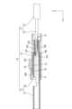
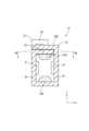
図2に示されるように、端子本体15は、板状をなす相手方端子が挿入可能な筒部17と、筒部17の後方に位置して電線11と接続される電線接続部20を有する。図2に示されるように、電線接続部20は後方に延出された上側挟持部18Aおよび下側挟持部18Bと、を備える。本実施形態にかかる端子12は、いわゆる雌端子と呼ばれるものであり、相手方端子は、いわゆる雄端子と呼ばれるものである。 As shown in FIG. 2 , the
図2に示されるように、筒部17は前後方向に延びる角筒状をなしている。筒部17の前端は、相手方端子が挿入可能に開口されている。筒部17の内部には、弾性変形可能な弾性接触片(図示せず)が配されている。弾性接触片は、筒部17の内壁から内方に突出するとともに前後方向に延びている。筒部17内に挿入された相手方端子は、弾性接触片を押圧して弾性変形させる。弾性変形した弾性接触片の弾発力によって、相手方端子は、筒部17の内壁と弾性接触片との間に挟まれる。これにより相手方端子と端子12とが電気的に接続される。 As shown in FIG. 2, the
図2に示されるように、筒部17の後方には角筒状をなす電線接続部20が設けられている。電線接続部20の上壁の後端部には上側挟持部18A(挟持部の一例)が後方に延びて設けられており、電線接続部20の下壁の後端部には下側挟持部18B(挟持部の一例)が後方に延びて設けられている。上側挟持部18Aと下側挟持部18Bは前後に延びた細長い形状をなしている。上側挟持部18Aと下側挟持部18Bの前後方向の長さ寸法は略同じに形成されている。 As shown in FIG. 2, a
図2に示されるように、上側挟持部18Aの下面には、後端部よりも前方の位置に、下方に突出する上側保持突部23Aが設けられている。下側挟持部18Bの上面の後端部には、上方に突出する下側保持突部23Bが設けられている。下側保持突部23Bと、上側保持突部23Aとは、前後方向についてずれた位置に設けられている。 As shown in FIG. 2, an
上側挟持部18Aの下面、および下側挟持部18Bの上面が、芯線13の表面に形成された酸化被膜に食い込んで酸化被膜を剥がすことにより、芯線13の金属表面を露出させるようになっている。この金属表面と、上側挟持部18Aおよび下側挟持部18Bとが接触することにより、芯線13と端子本体15とが電気的に接続される。 The lower surface of the
図3に示されるように、端子本体15の側壁には、外方に突出する係止突起28が形成されている。この係止突起28は、後述する仮係止受け部26および本係止受け部27と係止することにより、スライド部16を、仮係止位置(非接触位置の一例)および本係止位置(接触位置の一例)に保持するようになっている。 As shown in FIG. 3, the side wall of the
[スライド部16]
図3に示されるように、スライド部16は、前後方向に延びる角筒状をなしている。スライド部16は、金属板材を所定の形状にプレス加工することにより形成される。スライド部16を構成する金属は、銅、銅合金、アルミニウム、アルミニウム合金、ステンレス鋼等、必要に応じて任意の金属を適宜に選択できる。本実施形態にかかるスライド部16は、特に限定されないが、ステンレス鋼からなる。スライド部16の表面にはめっき層が形成されていてもよい。めっき層を構成する金属は、スズ、ニッケル、銀等必要に応じて任意の金属を適宜に選択できる。[Slide part 16]
As shown in FIG. 3, the
図2に示されるように、スライド部16の内形状の断面は、端子本体15のうち、上側挟持部18Aと下側挟持部18Bが設けられた領域の外形状の断面と同じか、やや大きく形成されている。これにより、スライド部16は、端子本体15のうち、上側挟持部18Aと下側挟持部18Bとが設けられた領域の外方に配されるようになっている。 As shown in FIG. 2, the cross section of the inner shape of the
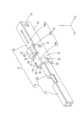
図4に示されるように、スライド部16は、下壁31と、下壁31の右側縁から上方に延びる右側壁39(第1側壁の一例)と、下壁31の左側縁から上方に延びる左側壁34(第2側壁の一例)と、下壁31、右側壁39および左側壁34により形成された空間を上方から覆う上壁30と、を備える。 As shown in FIG. 4, the
図4に示されるように、スライド部16の上壁30は、前後方向について3つの部分に分かれている。上壁30のうち、前後方向について中央付近に位置するものは第1上壁30Aとされる。第1上壁30Aの前方には第2上壁30Bが設けられている。第1上壁30Aの後方には第3上壁30Cが設けられている。 As shown in FIG. 4, the
図5に示されるように、第1上壁30Aは、右側壁39の上端部のうち、前後方向の中央付近から左方に延びて形成されている。右側壁39と第1上壁30Aとは、第1折れ曲がり部32を介してつながっている。第1折れ曲がり部32は、右側壁39と、第1上壁30Aとが略直角に折れ曲がった状態で、右側壁39と、第1上壁30Aとを連結している。 As shown in FIG. 5, the first
図5に示されるように、第1上壁30Aの下方には、左側壁34の上端部のうち、前後方向の中央付近から右方に延びて形成された第1重なり部52が形成されている。第1上壁30Aと、第1重なり部52とは、上方から見て、略同じ大きさの長方形状に形成されている。 As shown in FIG. 5, below the first
図6に示されるように、左側壁34と第2上壁30Bとは、第2折れ曲がり部33を介してつながっている。第2折れ曲がり部33は、左側壁34と、第2上壁30Bとが略直角に折れ曲がった状態で、左側壁34と、第2上壁30Bとを連結している。第2上壁30Bの右側縁には、前端部から後方に凹んだ凹部56が形成されている。この凹部56内には、右側壁39の上端部に設けられた前保持部55が配されるようになっている。前保持部55は、右側壁39の上端部のうち、凹部56に対応する領域が上方に突出した形状をなしている。 As shown in FIG. 6 , the
図7に示されるように、第2上壁30Bの下方には、右側壁39の上端部のうち、前保持部55の後方の部分が左方に延びた形状をなす、第2重なり部53が設けられている。第2重なり部53の左端部は、前方に延びて形成された延長部とされる。延長部の前端縁は、スライド部16の前端縁と面一に形成されている。 As shown in FIG. 7, below the second
第3上壁30Cは、右側壁39の上端部のうち、第1折れ曲がり部32よりも後方の部分が左方に延びて形成されている。 The third
図2に示されるように、スライド部16の下壁31の上面には、上方に突出する下側加圧部25B(加圧部の一例)が設けられている。スライド部16の第3上壁30Cの下方には、スライド部16の後端から前方に向かう方向について略二分の一の領域に、下方に突出する上側加圧部25A(加圧部の一例)が設けられている。 As shown in FIG. 2, the upper surface of the
図4に示されるように、スライド部16の左側壁34および右側壁39には、前後方向の前端部寄りの位置に、仮係止受け部26が開口されている。また、スライド部16の左側壁34および右側壁39には、仮係止受け部26よりも後方の位置に、本係止受け部27が開口されている。仮係止受け部26と、本係止受け部27は、端子本体15の左側壁および右側壁に設けられた係止突起28と弾性的に係止可能になっている。As shown in FIG. 4, the
端子本体15の係止突起28とスライド部16の仮係止受け部26とが係止した状態は、端子本体15に対してスライド部16が仮係止位置に保持された状態となっている(図8参照)。この状態においては、スライド部16の上側加圧部25Aおよび下側加圧部25Bは、端子本体15の上側挟持部18Aおよび下側挟持部18Bの後端縁よりも後方に位置している。これにより上側加圧部25Aおよび下側加圧部25Bは、それぞれ、上側挟持部18Aおよび下側挟持部18Bと接触していない状態になっている。後方に離間している。また、この状態においては、上側挟持部18Aと下側挟持部18Bとの間の間隔は、芯線13の直径よりも大きく設定されている(図9参照)。 A state in which the locking
端子本体15の係止突起28とスライド部16の本係止受け部27とが係止した状態は、端子本体15に対してスライド部16が本係止位置に係止された状態となっている。図2に示されるように、この状態においては、スライド部16の上側加圧部25Aは、上側挟持部18Aの上方から上側挟持部18Aに接触している。また、スライド部16の下側加圧部25Bは、下側挟持部18Bの下方から下側挟持部18Bに接触している。 The state in which the locking
上記のように、スライド部16は、端子本体15のうち上側挟持部18Aと下側挟持部18Bとが設けられた領域に外嵌された状態で、上記した仮係止位置と、本係止位置との間を前後方向についてスライド移動可能になっている。 As described above, the sliding
図2に示されるように、スライド部16が端子本体15に対して本係止位置で保持された状態では、上側加圧部25Aが上方から上側挟持部18Aを押圧することによって上側挟持部18Aが下方に変形するようになっている。また、下側加圧部25Bが下方から下側挟持部18Bを押圧することによって下側挟持部18Bが上方に変形するようになっている。これにより、上側挟持部18Aと下側挟持部18Bとの間の空間に、芯線13を前後方向に延びた状態で配し、且つ、スライド部16が端子本体15に対して本係止位置で保持した状態では、芯線13は、弾性変形した上側挟持部18Aと下側挟持部18Bによって上下方向から挟持されるようになっている。すなわち、上側挟持部18Aは上側加圧部25Aに下方に押圧されることにより芯線13に上方から接触し、下側挟持部18Bは下側加圧部25Bに上方に押圧されることにより芯線13に下方から接触するようになっている。 As shown in FIG. 2, when the
図2に示されるように、スライド部16が端子本体15に対して本係止位置で保持された状態では、上側挟持部18Aの上側保持突部23Aが芯線13を上方から押圧し、下側挟持部18Bの下側保持突部23Bが芯線13を下方から押圧する。このように、芯線13は、上側保持突部23Aによって上方から押圧されるとともに、上側保持突部23Aと前後方向にずれた位置に配された下側保持突部23Bによって下方から押圧されることにより、上下方向について屈曲した状態に保持される。また、上側保持突部23Aと、下側保持突部23Bとによっても、芯線13と端子12とが電気的に接続されるようになっている。 As shown in FIG. 2, when the
図8に示されるように、スライド部16の後端部寄りの位置には、左側壁34および右側壁39に、スライド部16の内方に突出する一対の誘い込み部47が設けられている。誘い込み部47は、後方から前方に向かうに従って幅狭に形成されている。誘い込み部47の内面に芯線13が摺接することにより、芯線13はスライド部16の内部へと案内される。 As shown in FIG. 8, the
第1上壁30Aは、スライド部16の右側壁39の上端縁のうち、前後方向について中央付近の部分が、左方に折れ曲がって形成されている。第1上壁30Aは上方から見て略長方形状をなしている。The first
図4に示されるように、第1上壁30Aの右側の領域には、上方に突出する突出部46が設けられている。換言すると、突出部46は、第1上壁30Aのうち第1折れ曲がり部32の近傍に形成されている。本実施形態にかかる突出部46は、第1折れ曲がり部32に連なって形成されている。突出部46は第1上壁30Aが曲げ加工されることにより形成されている。突出部46は、第1上壁30Aの前端部から後端部まで前後方向に延びて形成されている。突出部46は、後方から見て、下方に開口する角溝状に形成されている。突出部46の肉厚は均一に形成されている。均一に形成されているとは、突出部46の肉厚が、均一である場合を含むとともに、均一でない場合であっても実質的に均一と認められる場合も含む。換言すると、突出部46には、肉厚が極端に薄い部分が形成されていない。突出部46が前方に押されることにより、スライド部16が前方に移動可能になっている。 As shown in FIG. 4, a
突出部46を押圧する構造としては特に限定されず、例えば、公知の治具45を用いることができる。また、治具45に限られず、例えば、突出部46を押圧するアクチュエータを備えた製造設備によって突出部46が押圧される構成としてもよい。 The structure for pressing the projecting
図4に示されるように、第1上壁30Aの前端縁のうち、左端部寄りの部分は、突出部46が後方から治具45によって押圧されたときに、第2折れ曲がり部33の後端縁と接触する第1接触部50とされる。一方、第2折れ曲がり部33の後端縁は、後保持部54とされる。突出部46が後方から治具45によって押圧されると、第1接触部50が後保持部54に後方から接触することにより、第1上壁30Aの突出部46が後方から押圧された力が、後保持部54によって受けられるようになっている。 As shown in FIG. 4, of the front edge of the first
図4に示されるように、第2上壁30Bに形成された凹部56の後端部は、第1接触部50が、第2上壁30Bの後保持部54に後方から接触したときに、前保持部55に後方から接触する第2接触部51とされる。第2接触部51は、前保持部55の後方に位置している。 As shown in FIG. 4, when the
[電線11と端子12の接続工程]
続いて、電線11と端子12との接続工程の一例について説明する。電線11と端子12との接続工程は以下の記述に限定されない。[Connection process of
Next, an example of the process of connecting the
公知の手法により、端子本体15と、スライド部16とが形成される。端子本体15に対して、後方からスライド部16が組み付けられる。端子本体15の係止突起28に後方からスライド部16の前端縁が当接し、スライド部16の側壁が拡開変形する。さらにスライド部16が前方に押し込まれると、スライド部16の側壁が復帰変形し、端子本体15の係止突起28に、スライド部16の仮係止受け部26が係止する。これにより、端子本体15に対してスライド部16が仮係止位置に保持される(図8参照)。これにより端子12が得られる。 A
公知の手法で絶縁被覆14が皮剥ぎ加工されることにより電線11の芯線13が露出される。 The
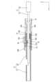
図9に示されるように、電線11がスライド部16の後端部から前方に押し込まれると、芯線13の前端部はスライド部16の内部へと導入される。芯線13はスライド部16の誘い込み部47と当接することにより、スライド部16へと案内される。さらに電線11が前方に押し込まれると、芯線13の前端部は端子本体15の内部へと進入して上側挟持部18Aと下側挟持部18Bとの間の空間内に至る。 As shown in FIG. 9 , when the
端子本体15に対してスライド部16が仮係止位置に保持された状態では、上側挟持部18Aと下側挟持部18Bとの間隔は、芯線13の外径寸法よりも大きく設定されている。 When the
次に、図10に示されるように、治具45を後方から突出部46に当接させて、スライド部16を前方にスライド移動させる。スライド部16は端子本体15に対して相対的に前方に移動させられる。このとき、端子本体15の係止突起28と、スライド部16の仮係止受け部26との係止が外れ、スライド部16の側壁が係止突起28に乗り上げて拡開変形する。 Next, as shown in FIG. 10, the
スライド部16が前方に移動させられると、スライド部16の側壁が復帰変形して端子本体15の係止突起28と、スライド部16の本係止受け部27とが弾性的に係止する。これによりスライド部16が端子本体15に対して本係止位置に保持される。 When the
図9に示されるように、前側から順に、第2上壁30Bの下方には第2重なり部53が配されており、第1上壁30Aの下方には第1重なり部52が配されている。第2重なり部53の下面と、第1重なり部52の下面と、第3上壁30Cの前端部の下面は、ほぼ面一に形成されている。これにより、上側挟持部18Aは、スライド部16の内部を、第2重なり部53の下面、および第1重なり部52の下面に案内されて、第3上壁30Cの前端部の下面へとスムーズに移動する。As shown in FIG. 9, in order from the front side, a second overlapping
スライド部16が端子本体15に対して本係止位置に保持された状態で、スライド部16の上側加圧部25Aが、端子本体15の上側挟持部18Aに上方から当接して下方へと押圧する。また、スライド部16の下側加圧部25Bが、端子本体15の下側挟持部18Bに下方から当接して上方へと押圧する。これにより、芯線13が、上側挟持部18Aと下側挟持部18Bに上下から挟持される。 While the
図2に示されるように、上側挟持部18Aの下面と、下側挟持部18Bの上面とに芯線13が挟まれることにより、芯線13の表面に形成された酸化被膜が剥がされ、芯線13を構成する金属表面が露出する。この金属表面と、上側挟持部18Aおよび下側挟持部18Bが接触することにより、電線11と端子12とが電気的に接続される。 As shown in FIG. 2, the
芯線13が上側挟持部18Aと下側挟持部18Bに上下から挟持された状態においては、芯線13は、上側挟持部18Aの上側保持突部23Aと、下側挟持部18Bの下側保持突部23Bとに挟まれることにより、前後方向に延びた状態で、且つ、上下方向に屈曲した状態で保持される。これにより、芯線13を強固に保持することができるので、電線11に引っ張り力が作用した場合に、電線11と端子12との保持力を高めることができる。このようにして端子付き電線10が完成する。 In a state in which the
[本実施形態の作用効果]
続いて、本実施形態の作用効果について説明する。本実施形態にかかる端子12は、電線11の前端部に接続される端子12であって、端子本体15と、スライド部16と、を備え、端子本体15は電線11を挟持する上側挟持部18Aおよび下側挟持部18Bを有し、スライド部16は、端子本体15に外嵌する筒状をなしており、スライド部16は、スライド部16の内面から内方に突出する上側加圧部25Aおよび下側加圧部25Bを有し、スライド部16は、端子本体15に対して、上側加圧部25Aおよび下側加圧部25Bが上側挟持部18Aおよび下側挟持部18Bと接触しない仮係止位置と、仮係止位置よりも前方の本係止位置であって上側加圧部25Aおよび下側加圧部25Bが上側挟持部18Aおよび下側挟持部18Bに接触する本係止位置と、の間でスライド可能に配されており、スライド部16は、下壁31と、下壁31の右側縁から上方に延びる右側壁39と、下壁31の左側縁から上方に延びる左側壁34と、を有し、右側壁39の上端部には、折れ曲がった第1折れ曲がり部32を介して左側壁34に向かって延びる第1上壁30Aが形成されており、左側壁34の上端部には、第1上壁30Aよりも前方の位置に、折れ曲がった第2折れ曲がり部33を介して右側壁39に向かって延びる第2上壁30Bが形成されており、第1上壁30Aには外方に突出する突出部46が形成されており、第2上壁30Bの後端縁または第2折れ曲がり部33の後端縁には、第1上壁30Aの突出部46が後方から押圧された力を受ける後保持部54が設けられている。[Action and effect of the present embodiment]
Next, the effects of this embodiment will be described. A terminal 12 according to the present embodiment is a terminal 12 connected to the front end of an
また、本実施形態にかかる端子付き電線10は、上記の端子12と、端子12に接続される電線11と、を備える。 Moreover, the
図10に示されるように、治具45によって突出部46が前方に押圧されると、突出部46が設けられた第1上壁30Aが前方に押圧される。すると、第1上壁30Aが全体として前方に押し出され、第1上壁30Aの前端縁が、後保持部54に後方から接触する。これにより、治具45が突出部46を前方に押圧する際に第1上壁30Aに加えられた力は、第2上壁30Bの後保持部54によって受けられる。これによりスライド部16の強度を向上させることができる。As shown in FIG. 10, when the
本実施形態によれば、後保持部54は第2折れ曲がり部33の後端縁を含み、第1上壁30Aの前端縁のうち左側壁34側の端部は、第1上壁30Aの突出部46が後方から押圧されたときに、第2折れ曲がり部33の後端縁と接触する第1接触部50とされる。 According to the present embodiment, the
第1上壁30Aは、前後方向に延びる第1折れ曲がり部32を介して右側壁39とつながっている。このため、第1上壁30Aは、治具45によって後方から押された場合でも、前方にまっすぐに移動できない。具体的には、第1折れ曲がり部32の後端部が支点のように機能して、上方から見て、矢線Aで示される方向に概ね回転するように動く。上記のように第1折れ曲がり部32は前後方向に延びているので、第1上壁30Aは完全な円運動をするわけではない。また、第1折れ曲がり部32の後端部が厳密な回転中心となるわけではない。The first
押圧部によって第1上壁30Aが後方から押圧されると、第1上壁30Aの前端縁のうち左側壁34側に形成された第1接触部50は、第2上壁30Bの後保持部54に後方から当接する。第2折れ曲がり部33は折れ曲がっているので、第2折れ曲がり部33の強度は、左側壁34および第2上壁30Bよりも大きくなっている。これによりスライド部16の強度を向上させることができる。When the pressing portion presses the first
本実施形態によれば、右側壁39の上端縁には、第1折れ曲がり部32よりも前方の位置に、上方に突出する前保持部55が形成されており、第2上壁30Bには、前保持部55の後方に、第2接触部51が設けられており、第2上壁30Bの後保持部54に加えられた力は、第2接触部51が前保持部55に後方から当接することによって受けられる。According to this embodiment, the upper edge ofthe
第2上壁30Bの後保持部54が、第1上壁30Aの第1接触部50によって後方から押圧されると、第2上壁30Bは全体としては前方に移動する。詳細に説明すると、第2上壁30Bと左側壁34とは、前後方向に延びる第2折れ曲がり部33によって連結されているので、第2上壁30Bは、前方にまっすぐに移動できない。具体的には、第2折れ曲がり部33の後端部が支点のように機能して、上方から見て、矢線Bで示される方向に概ね回転するように動く。上記のように第2折れ曲がり部33は前後方向に延びているので、第2上壁30Bは完全な円運動をするわけではない。また、第2折れ曲がり部33の後端部が厳密な回転中心となるわけではない。 When the
第1接触部50によって後保持部54が後方から押圧されると、第2上壁30Bのうち左側壁34側に形成された第2接触部51は、第1上壁30Aの前保持部55に後方から当接する。これにより第2接触部51が受けた力が前保持部55によって受けられるので、スライド部16の強度を向上させることができる。When the
本実施形態によれば、突出部46は、第1折れ曲がり部32の近傍に形成されている。 According to this embodiment, the projecting
治具45によって突出部46が後方から前方に押圧されると、第1上壁30Aは、上方から見て、第1折れ曲がり部32の後端部が支点のように機能することにより、概ね回転するように動く。突出部46は、支点のように機能する第1折れ曲がり部32の近傍に形成されているので、突出部46が後方から押圧されたときに、第1上壁30Aが回転しにくくなっている。これにより、スライド部16の強度を向上させることができる。When the projecting
本実施形態によれば、突出部46は、第1上壁30Aが曲げられて形成されている。 According to this embodiment, the
突出部46は、第1上壁30Aが曲げられることにより形成されているので、突出部46を構成する金属板材の厚さが、他の部分よりも薄くなる部分が形成されにくい。これにより、突出部46の強度を向上させることができるので、スライド部16の強度を向上させることができる。Since the protruding
本実施形態によれば、スライド部16は、第1上壁30Aの後方に第3上壁30Cを有し、上側加圧部25Aが第3上壁30Cに設けられている。According to this embodiment,the
第1上壁30Aに形成された突出部46が後方から押圧されると、この突出部46に加えられた力は、第1上壁30Aよりも前方に位置する第2上壁30Bによって受けられる。一方、上側挟持部18Aを押圧する上側加圧部25Aが第3上壁30Cに設けられていることにより、上側挟持部18Aから上側加圧部25Aに加えられる力は第3上壁30Cによって受けられる。これにより、突出部46が受ける力と、上側加圧部25Aが受ける力を1つの上壁で受ける場合に比べて、スライド部16に加えられる力を分散させることができる。これによりスライド部16の強度を向上させることができる。
When the projecting
<他の実施形態>
(1)実施形態1においては、突出部46は、第1上壁30Aの右端部寄りの位置に設けられる構成としたが、これに限られず、突出部46は、左右方向について、第1上壁30Aの中央付近に設けられる構成としてもよい。<Other embodiments>
(1) In the first embodiment, the projecting
(2)突出部46は、第1上壁30Aを上方に叩き出すことにより形成される構成としてもよい。(2) The projecting
(3)後保持部54は、第2上壁30Bの後端縁に形成されて、第2折れ曲がり部33には形成されない構成としてもよい。また、後保持部54は、第2上壁30Bの後端縁と、第2折れ曲がり部33の後端縁の双方に形成される構成としてもよい。(3) The
(4)前保持部55は省略してもよい。(4) The
(5)係止突起28、仮係止受け部26、および本係止受け部27は省略してもよい。(5) The locking
(6)実施形態1にかかる端子12は雌端子であったが、これに限られず、いわゆる雄端子であってもよい。(6) Although the terminal 12 according to the first embodiment is a female terminal, it is not limited to this, and may be a so-called male terminal.
10: 端子付き電線
11: 電線
12: 端子
13: 芯線
14: 絶縁被覆
15: 端子本体
16: スライド部
17: 筒部
18A: 上側挟持部
18B: 下側挟持部
20: 電線接続部
23A: 上側保持突部
23B: 下側保持突部
25A: 上側加圧部
25B: 下側加圧部
26: 仮係止受け部
27: 本係止受け部
28: 係止突起
30: 上壁
30A: 第1上壁
30B: 第2上壁
30C: 第3上壁
31: 下壁
32: 第1折れ曲がり部
33: 第2折れ曲がり部
34: 左側壁(第2側壁の一例)
39: 右側壁(第1側壁の一例)
45: 治具
46: 突出部
47: 誘い込み部
50: 第1接触部
51: 第2接触部
52: 第1重なり部
53: 第2重なり部
54: 後保持部
55: 前保持部
56: 凹部10: Electric wire with terminal 11: Electric wire 12: Terminal 13: Core wire 14: Insulating coating 15: Terminal body 16: Slide part 17:
39: Right side wall (an example of the first side wall)
45: Jig 46: Protruding portion 47: Guiding portion 50: First contact portion 51: Second contact portion 52: First overlapping portion 53: Second overlapping portion 54: Rear holding portion 55: Front holding portion 56: Concave portion
Claims (7)
Translated fromJapanese端子本体と、スライド部と、を備え、
前記端子本体は前記電線を挟持する挟持部を有し、
前記スライド部は、前記端子本体に外嵌する筒状をなしており、
前記スライド部は、前記スライド部の内面から内方に突出する加圧部を有し、
前記スライド部は、前記端子本体に対して、前記加圧部が前記挟持部と接触しない非接触位置と、前記非接触位置よりも前方の接触位置であって前記加圧部が前記挟持部に接触する前記接触位置と、の間でスライド可能に配されており、
前記スライド部は、下壁と、前記下壁の一方の側縁から上方に延びる第1側壁と、前記下壁の他方の側縁から上方に延びる第2側壁と、を有し、
前記第1側壁の上端部には、折れ曲がった第1折れ曲がり部を介して前記第2側壁に向かって延びる第1上壁が形成されており、前記第2側壁の上端部には、前記第1上壁よりも前方の位置に、折れ曲がった第2折れ曲がり部を介して前記第1側壁に向かって延びる第2上壁が形成されており、
前記第1上壁には外方に突出する突出部が形成されており、
前記第2上壁の後端縁または前記第2折れ曲がり部の後端縁には、
前記第1上壁の前記突出部が後方から押圧された力を受ける後保持部が設けられている端子。A terminal connected to the front end of an electric wire,
comprising a terminal body and a slide portion,
The terminal body has a clamping portion that clamps the electric wire,
The slide portion has a tubular shape that fits onto the terminal body,
The slide portion has a pressurizing portion protruding inward from an inner surface of the slide portion,
The sliding portion has a non-contact position where the pressing portion does not contact the clamping portion with respect to the terminal body, and a contact position forward of the non-contact position, where the pressing portion contacts the clamping portion. is arranged slidably between the contact position to contact,
The slide portion has a lower wall, a first side wall extending upward from one side edge of the lower wall, and a second side wall extending upward from the other side edge of the lower wall,
A first upper wall extending toward the second side wall via a first bent portion is formed at the upper end of the first side wall, and the first upper wall is formed at the upper end of the second side wall. A second upper wall extending toward the first side wall via a second bent portion is formed at a position forward of the upper wall,
The first upper wall is formed with a protruding portion that protrudes outward,
At the rear edge of the second upper wall or the rear edge of the second bent portion,
A terminal provided with a rear holding portion for receiving a force of pressing the projecting portion of the first upper wall from behind.
前記第1上壁の前端縁のうち前記第2側壁側の端部は、前記第1上壁の前記突出部が後方から押圧されたときに、前記第2折れ曲がり部の後端縁と接触する第1接触部とされる請求項1に記載の端子。the rear holding portion includes a rear edge of the second bent portion;
Of the front edge of the first upper wall, the end on the second side wall side comes into contact with the rear edge of the second bent portion when the projecting portion of the first upper wall is pressed from behind. 2. The terminal of claim 1, wherein the terminal is a first contact portion.
前記第2上壁には、前記前保持部の後方に、第2接触部が設けられており、
前記第2上壁の後保持部に加えられた力は、前記第2接触部が前記前保持部に後方から当接することによって受けられる請求項1または請求項2に記載の端子。A front holding portion projecting upward is formed at a position forward of the first bent portion on the upper edge of the first side wall,
The second upper wall is provided with a second contact portion behind the front holding portion,
3. The terminal according to claim 1, wherein the force applied to the rear holding portion of the second upper wall is received by the second contact portion coming into contact with the front holding portion from behind.
前記端子に接続される電線と、を備えた端子付き電線。a terminal according to any one of claims 1 to 6;
and an electric wire connected to the terminal.
Priority Applications (4)
| Application Number | Priority Date | Filing Date | Title |
|---|---|---|---|
| JP2020043008AJP7310661B2 (en) | 2020-03-12 | 2020-03-12 | Terminals and wires with terminals |
| PCT/JP2021/008880WO2021182373A1 (en) | 2020-03-12 | 2021-03-08 | Terminal and electrical wire with terminal |
| CN202180018800.4ACN115244788B (en) | 2020-03-12 | 2021-03-08 | Terminal and electric wire with terminal |
| US17/909,431US12230933B2 (en) | 2020-03-12 | 2021-03-08 | Terminal and wire with terminal |
Applications Claiming Priority (1)
| Application Number | Priority Date | Filing Date | Title |
|---|---|---|---|
| JP2020043008AJP7310661B2 (en) | 2020-03-12 | 2020-03-12 | Terminals and wires with terminals |
Publications (3)
| Publication Number | Publication Date |
|---|---|
| JP2021144870A JP2021144870A (en) | 2021-09-24 |
| JP2021144870A5 JP2021144870A5 (en) | 2022-07-28 |
| JP7310661B2true JP7310661B2 (en) | 2023-07-19 |
Family
ID=77672337
Family Applications (1)
| Application Number | Title | Priority Date | Filing Date |
|---|---|---|---|
| JP2020043008AActiveJP7310661B2 (en) | 2020-03-12 | 2020-03-12 | Terminals and wires with terminals |
Country Status (4)
| Country | Link |
|---|---|
| US (1) | US12230933B2 (en) |
| JP (1) | JP7310661B2 (en) |
| CN (1) | CN115244788B (en) |
| WO (1) | WO2021182373A1 (en) |
Families Citing this family (2)
| Publication number | Priority date | Publication date | Assignee | Title |
|---|---|---|---|---|
| JP7088110B2 (en)* | 2019-03-28 | 2022-06-21 | 株式会社オートネットワーク技術研究所 | Joint connector |
| JP7121913B2 (en)* | 2019-05-08 | 2022-08-19 | 株式会社オートネットワーク技術研究所 | Terminals and wires with terminals |
Citations (4)
| Publication number | Priority date | Publication date | Assignee | Title |
|---|---|---|---|---|
| JP2013229221A (en) | 2012-04-26 | 2013-11-07 | Sumitomo Wiring Syst Ltd | Terminal metal fitting |
| WO2019159730A1 (en) | 2018-02-15 | 2019-08-22 | 株式会社オートネットワーク技術研究所 | Terminal |
| JP2019145208A (en) | 2018-02-15 | 2019-08-29 | 株式会社オートネットワーク技術研究所 | Terminal and connector |
| JP2019204747A (en) | 2018-05-25 | 2019-11-28 | 株式会社オートネットワーク技術研究所 | Terminal |
Family Cites Families (4)
| Publication number | Priority date | Publication date | Assignee | Title |
|---|---|---|---|---|
| JPH07326415A (en)* | 1994-05-27 | 1995-12-12 | Ryosei Denso Kk | Connector terminal |
| EP2472675B1 (en) | 2003-07-30 | 2020-09-30 | The Furukawa Electric Co., Ltd. | Terminal crimping structure and terminal crimping method onto aluminum electric-wire |
| JP5629430B2 (en)* | 2008-12-09 | 2014-11-19 | 矢崎総業株式会社 | Terminal crimping structure to aluminum wire |
| JP6537905B2 (en)* | 2015-06-30 | 2019-07-03 | 日本航空電子工業株式会社 | connector |
- 2020
- 2020-03-12JPJP2020043008Apatent/JP7310661B2/enactiveActive
- 2021
- 2021-03-08USUS17/909,431patent/US12230933B2/enactiveActive
- 2021-03-08WOPCT/JP2021/008880patent/WO2021182373A1/ennot_activeCeased
- 2021-03-08CNCN202180018800.4Apatent/CN115244788B/enactiveActive
Patent Citations (4)
| Publication number | Priority date | Publication date | Assignee | Title |
|---|---|---|---|---|
| JP2013229221A (en) | 2012-04-26 | 2013-11-07 | Sumitomo Wiring Syst Ltd | Terminal metal fitting |
| WO2019159730A1 (en) | 2018-02-15 | 2019-08-22 | 株式会社オートネットワーク技術研究所 | Terminal |
| JP2019145208A (en) | 2018-02-15 | 2019-08-29 | 株式会社オートネットワーク技術研究所 | Terminal and connector |
| JP2019204747A (en) | 2018-05-25 | 2019-11-28 | 株式会社オートネットワーク技術研究所 | Terminal |
Also Published As
| Publication number | Publication date |
|---|---|
| US20230137240A1 (en) | 2023-05-04 |
| WO2021182373A1 (en) | 2021-09-16 |
| US12230933B2 (en) | 2025-02-18 |
| JP2021144870A (en) | 2021-09-24 |
| CN115244788A (en) | 2022-10-25 |
| CN115244788B (en) | 2025-08-12 |
Similar Documents
| Publication | Publication Date | Title |
|---|---|---|
| JP7158349B2 (en) | Terminals and wires with terminals | |
| JP6652583B2 (en) | Wire with terminal | |
| JP7183914B2 (en) | Terminals and wires with terminals | |
| JP7310661B2 (en) | Terminals and wires with terminals | |
| JP7121913B2 (en) | Terminals and wires with terminals | |
| WO2020250800A1 (en) | Terminal and terminal-equipped wire | |
| JP7133513B2 (en) | Terminals and wires with terminals | |
| JP7099394B2 (en) | Terminals and wires with terminals | |
| JP7216895B2 (en) | Terminals and wires with terminals | |
| JP7113796B2 (en) | Terminals and wires with terminals | |
| JP7152993B2 (en) | Terminals and wires with terminals | |
| JP7100809B2 (en) | Terminals and wires with terminals | |
| WO2021241294A1 (en) | Terminal, and electric cable with terminal |
Legal Events
| Date | Code | Title | Description |
|---|---|---|---|
| A521 | Request for written amendment filed | Free format text:JAPANESE INTERMEDIATE CODE: A523 Effective date:20220720 | |
| A621 | Written request for application examination | Free format text:JAPANESE INTERMEDIATE CODE: A621 Effective date:20220930 | |
| TRDD | Decision of grant or rejection written | ||
| A01 | Written decision to grant a patent or to grant a registration (utility model) | Free format text:JAPANESE INTERMEDIATE CODE: A01 Effective date:20230606 | |
| A61 | First payment of annual fees (during grant procedure) | Free format text:JAPANESE INTERMEDIATE CODE: A61 Effective date:20230619 | |
| R150 | Certificate of patent or registration of utility model | Ref document number:7310661 Country of ref document:JP Free format text:JAPANESE INTERMEDIATE CODE: R150 |