JP7309551B2 - memory system - Google Patents
memory systemDownload PDFInfo
- Publication number
- JP7309551B2 JP7309551B2JP2019170681AJP2019170681AJP7309551B2JP 7309551 B2JP7309551 B2JP 7309551B2JP 2019170681 AJP2019170681 AJP 2019170681AJP 2019170681 AJP2019170681 AJP 2019170681AJP 7309551 B2JP7309551 B2JP 7309551B2
- Authority
- JP
- Japan
- Prior art keywords
- value
- decoding
- llr
- memory
- estimated
- Prior art date
- Legal status (The legal status is an assumption and is not a legal conclusion. Google has not performed a legal analysis and makes no representation as to the accuracy of the status listed.)
- Active
Links
Images


Classifications
- G—PHYSICS
- G06—COMPUTING OR CALCULATING; COUNTING
- G06F—ELECTRIC DIGITAL DATA PROCESSING
- G06F11/00—Error detection; Error correction; Monitoring
- G06F11/07—Responding to the occurrence of a fault, e.g. fault tolerance
- G06F11/08—Error detection or correction by redundancy in data representation, e.g. by using checking codes
- G06F11/10—Adding special bits or symbols to the coded information, e.g. parity check, casting out 9's or 11's
- G06F11/1008—Adding special bits or symbols to the coded information, e.g. parity check, casting out 9's or 11's in individual solid state devices
- G06F11/1068—Adding special bits or symbols to the coded information, e.g. parity check, casting out 9's or 11's in individual solid state devices in sector programmable memories, e.g. flash disk
- H—ELECTRICITY
- H03—ELECTRONIC CIRCUITRY
- H03M—CODING; DECODING; CODE CONVERSION IN GENERAL
- H03M13/00—Coding, decoding or code conversion, for error detection or error correction; Coding theory basic assumptions; Coding bounds; Error probability evaluation methods; Channel models; Simulation or testing of codes
- H03M13/37—Decoding methods or techniques, not specific to the particular type of coding provided for in groups H03M13/03 - H03M13/35
- H03M13/3707—Adaptive decoding and hybrid decoding, e.g. decoding methods or techniques providing more than one decoding algorithm for one code
- G—PHYSICS
- G06—COMPUTING OR CALCULATING; COUNTING
- G06F—ELECTRIC DIGITAL DATA PROCESSING
- G06F11/00—Error detection; Error correction; Monitoring
- G06F11/07—Responding to the occurrence of a fault, e.g. fault tolerance
- G06F11/08—Error detection or correction by redundancy in data representation, e.g. by using checking codes
- G06F11/10—Adding special bits or symbols to the coded information, e.g. parity check, casting out 9's or 11's
- G06F11/1008—Adding special bits or symbols to the coded information, e.g. parity check, casting out 9's or 11's in individual solid state devices
- G06F11/1012—Adding special bits or symbols to the coded information, e.g. parity check, casting out 9's or 11's in individual solid state devices using codes or arrangements adapted for a specific type of error
- H—ELECTRICITY
- H03—ELECTRONIC CIRCUITRY
- H03M—CODING; DECODING; CODE CONVERSION IN GENERAL
- H03M13/00—Coding, decoding or code conversion, for error detection or error correction; Coding theory basic assumptions; Coding bounds; Error probability evaluation methods; Channel models; Simulation or testing of codes
- H03M13/29—Coding, decoding or code conversion, for error detection or error correction; Coding theory basic assumptions; Coding bounds; Error probability evaluation methods; Channel models; Simulation or testing of codes combining two or more codes or code structures, e.g. product codes, generalised product codes, concatenated codes, inner and outer codes
- H03M13/2948—Iterative decoding
- H—ELECTRICITY
- H03—ELECTRONIC CIRCUITRY
- H03M—CODING; DECODING; CODE CONVERSION IN GENERAL
- H03M13/00—Coding, decoding or code conversion, for error detection or error correction; Coding theory basic assumptions; Coding bounds; Error probability evaluation methods; Channel models; Simulation or testing of codes
- H03M13/37—Decoding methods or techniques, not specific to the particular type of coding provided for in groups H03M13/03 - H03M13/35
- H03M13/3723—Decoding methods or techniques, not specific to the particular type of coding provided for in groups H03M13/03 - H03M13/35 using means or methods for the initialisation of the decoder
- H—ELECTRICITY
- H03—ELECTRONIC CIRCUITRY
- H03M—CODING; DECODING; CODE CONVERSION IN GENERAL
- H03M13/00—Coding, decoding or code conversion, for error detection or error correction; Coding theory basic assumptions; Coding bounds; Error probability evaluation methods; Channel models; Simulation or testing of codes
- H03M13/37—Decoding methods or techniques, not specific to the particular type of coding provided for in groups H03M13/03 - H03M13/35
- H03M13/45—Soft decoding, i.e. using symbol reliability information
- H—ELECTRICITY
- H03—ELECTRONIC CIRCUITRY
- H03M—CODING; DECODING; CODE CONVERSION IN GENERAL
- H03M13/00—Coding, decoding or code conversion, for error detection or error correction; Coding theory basic assumptions; Coding bounds; Error probability evaluation methods; Channel models; Simulation or testing of codes
- H03M13/03—Error detection or forward error correction by redundancy in data representation, i.e. code words containing more digits than the source words
- H03M13/05—Error detection or forward error correction by redundancy in data representation, i.e. code words containing more digits than the source words using block codes, i.e. a predetermined number of check bits joined to a predetermined number of information bits
- H03M13/11—Error detection or forward error correction by redundancy in data representation, i.e. code words containing more digits than the source words using block codes, i.e. a predetermined number of check bits joined to a predetermined number of information bits using multiple parity bits
- H03M13/1102—Codes on graphs and decoding on graphs, e.g. low-density parity check [LDPC] codes
- H—ELECTRICITY
- H03—ELECTRONIC CIRCUITRY
- H03M—CODING; DECODING; CODE CONVERSION IN GENERAL
- H03M13/00—Coding, decoding or code conversion, for error detection or error correction; Coding theory basic assumptions; Coding bounds; Error probability evaluation methods; Channel models; Simulation or testing of codes
- H03M13/03—Error detection or forward error correction by redundancy in data representation, i.e. code words containing more digits than the source words
- H03M13/05—Error detection or forward error correction by redundancy in data representation, i.e. code words containing more digits than the source words using block codes, i.e. a predetermined number of check bits joined to a predetermined number of information bits
- H03M13/13—Linear codes
- H03M13/15—Cyclic codes, i.e. cyclic shifts of codewords produce other codewords, e.g. codes defined by a generator polynomial, Bose-Chaudhuri-Hocquenghem [BCH] codes
- H03M13/151—Cyclic codes, i.e. cyclic shifts of codewords produce other codewords, e.g. codes defined by a generator polynomial, Bose-Chaudhuri-Hocquenghem [BCH] codes using error location or error correction polynomials
- H03M13/1515—Reed-Solomon codes
- H—ELECTRICITY
- H03—ELECTRONIC CIRCUITRY
- H03M—CODING; DECODING; CODE CONVERSION IN GENERAL
- H03M13/00—Coding, decoding or code conversion, for error detection or error correction; Coding theory basic assumptions; Coding bounds; Error probability evaluation methods; Channel models; Simulation or testing of codes
- H03M13/03—Error detection or forward error correction by redundancy in data representation, i.e. code words containing more digits than the source words
- H03M13/05—Error detection or forward error correction by redundancy in data representation, i.e. code words containing more digits than the source words using block codes, i.e. a predetermined number of check bits joined to a predetermined number of information bits
- H03M13/13—Linear codes
- H03M13/15—Cyclic codes, i.e. cyclic shifts of codewords produce other codewords, e.g. codes defined by a generator polynomial, Bose-Chaudhuri-Hocquenghem [BCH] codes
- H03M13/151—Cyclic codes, i.e. cyclic shifts of codewords produce other codewords, e.g. codes defined by a generator polynomial, Bose-Chaudhuri-Hocquenghem [BCH] codes using error location or error correction polynomials
- H03M13/152—Bose-Chaudhuri-Hocquenghem [BCH] codes
Landscapes
- Engineering & Computer Science (AREA)
- Theoretical Computer Science (AREA)
- Physics & Mathematics (AREA)
- Probability & Statistics with Applications (AREA)
- Quality & Reliability (AREA)
- General Engineering & Computer Science (AREA)
- General Physics & Mathematics (AREA)
- Error Detection And Correction (AREA)
- Detection And Correction Of Errors (AREA)
- Techniques For Improving Reliability Of Storages (AREA)
Description
Translated fromJapanese以下の実施形態は、メモリシステムに関する。 The following embodiments relate to memory systems.
フラッシュメモリ等の不揮発性メモリを備えたメモリシステムでは、データ保護の観点から、一般的に、不揮発性メモリに書き込むデータを符号化する。このため、メモリシステムに記憶されたデータを読み出す際には、符号化されたデータに対する復号が行われる。 In a memory system with non-volatile memory such as flash memory, data to be written into the non-volatile memory is generally encoded from the viewpoint of data protection. Therefore, when reading the data stored in the memory system, the encoded data is decoded.
不揮発性メモリに記憶されたデータの読出し方式としては、例えば、硬判定読出し(ハードビットリードともいう)と軟判定読出し(ソフトビットリードともいう)とが存在する。不揮発性メモリの各メモリセルが1ビットのデータを記憶するシングルレベルセル(SLC)である場合の硬判定読出しでは、各メモリセルに記憶されているデータが‘0’又は‘1’のビット値として読み出される。一方、SLCに対する軟判定読出しでは、記憶されているデータが‘0’であるか‘1’であるかの確率に関する情報として読み出される。この確率に関する情報には、対数尤度比(LLR:Log-Likelihood Ratio)が用いられるのが一般的である。LLRは、記憶されたビットが‘0’である確率と‘1’である確率とを対数比で表現した情報である。軟判定読出しでは、不揮発性メモリから読み出されたデータがLLRテーブルと呼ばれる事前に作成されたテーブルに従ってLLR列に変換されて復号される。 Methods for reading data stored in a nonvolatile memory include, for example, hard-decision reading (also referred to as hard-bit reading) and soft-decision reading (also referred to as soft-bit read). When each memory cell of the nonvolatile memory is a single-level cell (SLC) that stores 1-bit data, in hard-decision reading, the data stored in each memory cell is a bit value of '0' or '1'. is read as On the other hand, soft-decision reading for SLC is read as information relating to the probability that the stored data is '0' or '1'. Log-Likelihood Ratio (LLR) is generally used as the information about this probability. The LLR is information expressing the probability that a stored bit is '0' and '1' in a logarithmic ratio. In soft-decision reading, data read from non-volatile memory is converted into LLR sequences and decoded according to a pre-created table called an LLR table.
本発明の実施形態は、通信路の不一致に基づく復号特性の劣化を抑えることが可能なメモリシステムを提供することを目的とする。 An object of the embodiments of the present invention is to provide a memory system capable of suppressing degradation of decoding characteristics due to mismatch of communication channels.
実施形態のメモリシステムは、不揮発性メモリと、メモリコントローラと、を備える。メモリコントローラは、不揮発性メモリから読み出された受信値を、第1変換テーブルを用いて第1尤度情報に変換し、第1尤度情報に対して復号を実行して事後値を出力し、復号に成功した場合、事後値に基づいて得られる、受信値の推定値を出力し、復号に失敗した場合、事後値に基づいて、第2変換テーブルを作成し、第2変換テーブルを作成した場合、第2変換テーブルを用いて受信値を第2尤度情報に変換し、第2尤度情報に対して復号を実行して事後値を出力する。 A memory system according to an embodiment includes a nonvolatile memory and a memory controller. The memory controller converts the received value read from the nonvolatile memory into the first likelihood information using the first conversion table, decodes the first likelihood information, and outputs the posterior value. , if decoding is successful, output an estimated value of the received value obtained based on the posterior value; if decoding fails, create a second conversion table based on the posterior value, and create a second conversion table; If so, the received value is converted into the second likelihood information using the second conversion table, the second likelihood information is decoded, and the posterior value is output.
以下に添付図面を参照して、実施形態に係るメモリシステムを詳細に説明する。なお、以下の実施形態により本発明が限定されるものではない。 Memory systems according to embodiments will be described in detail below with reference to the accompanying drawings. In addition, the present invention is not limited by the following embodiments.
また、実施形態を説明するにあたり、用語について以下のように定義する。
「通信路(ストレスともいう)」とは、書込み値(送信値ともいう)xへの雑音の影響を表す確率モデルであり、通信路行列で特徴付けられるものである。なお、通信路行列を特徴付ける要因としては、いわゆるプログラムディスターブやデータリテンションやリードディスターブや温度交差などが考えられる。
「尤度」とは、ある書込み値xが与えられたときに通信路の出力値(受信値ともいう)yが得られる条件付き確率P(y|x)である。
「通信路行列」とは、尤度を全ての(x,y)の組に関して記載した行列である。
「対数尤度比(LLR)」とは、記憶されたビットが‘0’である時の尤度と‘1’である時の尤度とを対数比で表現した情報であり、尤度情報とも、LLR値とも称される。
「事後確率」とは、受信値yが得られたときに、書込み値がxである条件付き確率P(x|y)である。
「事後LLR」とは、事後確率に関する対数尤度比である。例えば事後LLRは、受信値yが得られたときに、書込み値が‘0’である条件付き確率P(0|y)と書込み値が‘1’である条件付き確率P(1|y)とを対数比で表現した情報である。
「LLRテーブル」とは、通信路の出力値yと復号器の入力であるLLRとの対応関係を示すテーブル(変換テーブル)である。LLRテーブルにより、出力値yがLLR値に変換される。すなわち、通信路行列から得られた値ln[P(y|x=0)/P(y|x=1)]が出力値yに対応するLLR値となる。一般的に、異なる通信路行列に対しては、異なるLLRテーブルが用意される。
「既定のLLRテーブル」とは、デフォルトで使用されるLLRテーブルである。この既定のLLRテーブルには、例えば、多様な通信路での訂正が想定される中で、典型的に使用されそうな通信路から得られたLLRテーブルが用いられる。
「ECCフレーム」とは、復号器が動作するためのデータブロックであり、受信値の系列から符号語を再構成するためのデータブロックのことである。
「復号結果の推定書込み値(推定値ともいう)k」は、復号器の出力である一つ一つの推定書込み値である。従って、復号の終了時には、ECCフレームに対応する推定書込み値kの系列{k}が得られる。なお、復号に成功するとは、答えの系列{x}と復号結果の系列{k}とが完全に一意することを意味する。一方、復号に失敗するとは、ECCフレーム内でx≠kとなる箇所が発生し、系列{x}と{k}とが一致しないことを意味する。真に復号の成否を知るためには、答えの系列を知らなければならない。復号器は答えの系列を知らないので、真の復号の成否は分からないが、復号の成否の推定情報は持つ。以下で復号を説明する文脈で、単に復号の成否といった場合、復号器が推定した成否であることを意味する。
「真の通信路行列」とは、正確な答えであるxに基づいた条件付き確率P(y|x)を要素とした通信路行列である。一方、「推定通信路行列」とは、復号器から出力された推定書込み値kを用いた条件付き確率P(y|k)を要素とした通信路行列である。
「推定LLRテーブル」とは、復号結果から推定されるLLRテーブルである。
「シンボル」とは、誤り訂正符号の少なくとも一つ以上の構成単位である。1シンボルは、例えば1ビット(二元体(binary field)の元(element))、または、二元体以外の有限体(finite field)などのアルファベットの元で構成される。In describing the embodiments, terms are defined as follows.
A "channel (also referred to as stress)" is a probabilistic model of the effect of noise on a written value (also referred to as a transmitted value) x, characterized by a channel matrix. Factors that characterize the communication path matrix include so-called program disturb, data retention, read disturb, temperature crossing, and the like.
"Likelihood" is a conditional probability P(y|x) that an output value (also called a received value) y of a communication channel is obtained given a certain written value x.
A "channel matrix" is a matrix that describes the likelihood for every (x,y) pair.
"Log-likelihood ratio (LLR)" is information expressing the likelihood when a stored bit is '0' and the likelihood when it is '1' in terms of a logarithmic ratio. Both are also referred to as LLR values.
The "posterior probability" is the conditional probability P(x|y) that the written value is x given the received value y.
"Posterior LLR" is the log-likelihood ratio for the posterior probability. For example, the posterior LLR is the conditional probability P(0|y) that the written value is '0' and the conditional probability P(1|y) that the written value is '1' when the received value y is obtained. is information expressed in logarithmic ratio.
The “LLR table” is a table (conversion table) that indicates the correspondence between the output value y of the communication path and the LLR that is the input of the decoder. The LLR table converts the output value y to an LLR value. That is, the value ln[P(y|x=0)/P(y|x=1)] obtained from the channel matrix is the LLR value corresponding to the output value y. Generally, different LLR tables are prepared for different channel matrices.
A "default LLR table" is an LLR table used by default. For this default LLR table, for example, an LLR table obtained from a communication channel that is likely to be typically used while corrections in various communication channels are assumed is used.
An "ECC frame" is a data block for a decoder to operate on and reconstruct a codeword from a sequence of received values.
The “estimated written value (also called estimated value) k of the decoding result” is each estimated written value that is the output of the decoder. Therefore, at the end of decoding, a sequence {k} of estimated written values k corresponding to the ECC frame is obtained. Successful decoding means that the sequence {x} of the answer and the sequence {k} of the decoding result are completely unique. On the other hand, decoding failure means that there is a place where x≠k in the ECC frame, and the sequences {x} and {k} do not match. In order to truly know the success or failure of decoding, the sequence of answers must be known. Since the decoder does not know the sequence of the answers, it does not know whether the decoding was successful or not, but it does have information about the success or failure of the decoding. In the context of describing decoding below, when we simply refer to decoding success or failure, we mean the decoder's inferred success or failure.
A "true channel matrix" is a channel matrix whose elements are conditional probabilities P(y|x) based on the correct answer x. On the other hand, the "estimated channel matrix" is a channel matrix whose elements are the conditional probabilities P(y|k) using the estimated write value k output from the decoder.
The “estimated LLR table” is an LLR table estimated from the decoding result.
A "symbol" is at least one or more constituent units of an error correcting code. One symbol is composed of, for example, one bit (element of a binary field) or an element of an alphabet such as a finite field other than a binary field.
(第1の実施形態)
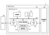
まず、第1の実施形態に係るメモリシステムについて、図面を参照して詳細に説明する。図1は、第1の実施形態に係るメモリシステムの概略構成例を示すブロック図である。図1に示すように、メモリシステム1は、メモリコントローラ10と不揮発性メモリ20とを備える。メモリシステム1は、ホスト30と接続可能であり、図1ではホスト30と接続された状態が示されている。ホスト30は、例えば、パーソナルコンピュータ、携帯端末などの電子機器であってよい。(First embodiment)
First, the memory system according to the first embodiment will be described in detail with reference to the drawings. FIG. 1 is a block diagram showing a schematic configuration example of a memory system according to the first embodiment. As shown in FIG. 1, the
不揮発性メモリ20は、データを不揮発に記憶する不揮発性メモリであり、例えば、NAND型フラッシュメモリ(以下、単にNANDメモリという)である。以下の説明では、不揮発性メモリ20としてNANDメモリが用いられた場合を例示するが、不揮発性メモリ20として3次元構造フラッシュメモリ、ReRAM(Resistive Random Access Memory)、FeRAM(Ferroelectric Random Access Memory)等のNANDメモリ以外の記憶装置を用いることも可能である。また、不揮発性メモリ20が半導体メモリであることは必須ではなく、半導体メモリ以外の種々の記憶媒体に対して本実施形態を適用することも可能である。 The
メモリシステム1は、いわゆるSSD(Solid State Drive)や、メモリコントローラ10と不揮発性メモリ20とが1つのパッケージとして構成されるメモリカード等、不揮発性メモリ20を備える種々のメモリシステムであってよい。 The
メモリコントローラ10は、ホスト30からの書込み要求に従って不揮発性メモリ20への書込みを制御する。また、メモリコントローラ10は、ホスト30からの読出し要求に従って不揮発性メモリ20からの読み出しを制御する。メモリコントローラ10は、例えばSoC(System On a Chip)として構成される半導体集積回路である。メモリコントローラ10は、ホストI/F(ホストインタフェース)15、メモリI/F(メモリインタフェース)13、制御部11、符号化/復号部(コーデック)14及びデータバッファ12を備える。ホストI/F15、メモリI/F13、制御部11、符号化/復号部14及びデータバッファ12は、内部バス16で相互に接続されている。以下で説明するメモリコントローラ10の各構成要素の動作の一部又は全部は、CPU(Central Processing Unit)がファームウエアを実行することによって実現されてもよいし、ハードウエアで実現されてもよい。 The
ホストI/F15は、ホスト30との間のインタフェース規格に従った処理を実施し、ホスト30から受信した命令、書込み対象のユーザデータなどを内部バス16に出力する。また、ホストI/F15は、不揮発性メモリ20から読み出されて復元されたユーザデータ、制御部11からの応答などをホスト30へ送信する。 The host I/
メモリI/F13は、制御部11の指示に基づいて、不揮発性メモリ20への書込み処理を行う。また、メモリI/F13は、制御部11の指示に基づいて、不揮発性メモリ20からの読み出し処理を行う。 The memory I/
制御部11は、メモリシステム1の各構成要素を統括的に制御する。制御部11は、ホスト30からホストI/F15経由で命令を受けた場合に、その命令に従った制御を行う。例えば、制御部11は、ホスト30からの命令に従って、不揮発性メモリ20へのユーザデータ及びパリティの書き込みをメモリI/F13へ指示する。また、制御部11は、ホスト30からの命令に従って、不揮発性メモリ20からのユーザデータ及びパリティの読み出しをメモリI/F13へ指示する。 The
また、制御部11は、ホスト30から書込み要求を受信した場合、データバッファ12に蓄積されるユーザデータに対して、不揮発性メモリ20上の記憶領域(メモリ領域)を決定する。すなわち、制御部11は、ユーザデータの書込み先を管理する。ホスト30から受信したユーザデータの論理アドレスと該ユーザデータが記憶された不揮発性メモリ20上の記憶領域を示す物理アドレスとの対応はアドレス変換テーブルとして記憶される。 Further, when receiving a write request from the
また、制御部11は、ホスト30から読出し要求を受信した場合、読出し要求により指定された論理アドレスを上述のアドレス変換テーブルを用いて物理アドレスに変換し、該物理アドレスからの読み出しをメモリI/F13へ指示する。 Further, when receiving a read request from the
NANDメモリでは、一般に、ページと呼ばれるデータ単位で、書き込み及び読み出しが行われ、ブロックと呼ばれるデータ単位で消去が行われる。本実施形態では、この同一のワード線に接続される複数のメモリセルをメモリセルグループと呼ぶ。メモリセルがシングルレベルセル(SLC:Single Level Cell)である場合は、1つのメモリセルグループが1ページに対応する。メモリセルがマルチレベルセル(MLC:Multiple Level Cell)である場合は、1つのメモリセルグループが複数ページに対応する。なお、本説明において、MLCには、TLC(Triple Level Cell)やQLC(Quad Level Cell)等が含まれる。また、各メモリセルはワード線に接続するとともにビット線にも接続される。従って、各メモリセルは、ワード線を識別するアドレスとビット線を識別するアドレスとで識別することが可能である。 In a NAND memory, writing and reading are generally performed in units of data called pages, and erasing is performed in units of data called blocks. In this embodiment, a plurality of memory cells connected to the same word line is called a memory cell group. If the memory cells are single level cells (SLC), one memory cell group corresponds to one page. If the memory cells are multi-level cells (MLC), one memory cell group corresponds to multiple pages. In this description, MLC includes TLC (Triple Level Cell), QLC (Quad Level Cell), and the like. Each memory cell is connected to a word line and also to a bit line. Therefore, each memory cell can be identified by an address that identifies a word line and an address that identifies a bit line.
データバッファ12は、メモリコントローラ10がホスト30から受信したユーザデータを不揮発性メモリ20へ記憶するまでに一時記憶する。また、データバッファ12は、不揮発性メモリ20から読み出したユーザデータをホスト30へ送信するまでに一時記憶する。データバッファ12には、例えば、SRAM(Static Random Access Memory)やDRAM(Dynamic Random Access Memory)などの汎用メモリを用いることができる。なお、データバッファ12は、メモリコントローラ10に内蔵されずに、メモリコントローラ10の外部に搭載されてもよい。 The
ホスト30から送信されるユーザデータは、内部バス16に転送されてデータバッファ12に一旦記憶される。符号化/復号部14は、不揮発性メモリ20に記憶されるユーザデータを符号化して符号語を生成する。また、符号化/復号部14は、不揮発性メモリ20から読み出された受信語を復号してユーザデータを復元する。そこで符号化/復号部14は、符号化部(Encoder)17と復号部(Decoder)18を備える。なお、符号化/復号部14により符号化されるデータには、ユーザデータ以外にも、メモリコントローラ10内部で用いる制御データ等が含まれてもよい。 User data transmitted from the
次に、本実施形態の書込み処理について説明する。制御部11は、不揮発性メモリ20への書込み時に、ユーザデータの符号化を符号化部17に指示する。その際、制御部11は、不揮発性メモリ20における符号語の記憶場所(記憶アドレス)を決定し、決定した記憶場所もメモリI/F13へ指示する。 Next, write processing of this embodiment will be described. The
符号化部17は、制御部11からの指示に基づいて、データバッファ12上のユーザデータを符号化して符号語を生成する。符号化方式としては、例えば、BCH(Bose-Chaudhuri-Hocquenghem)符号、および、RS(Reed-Solomon)符号のような代数的符号を用いた符号化方式、これらの符号を成分符号として用いた符号化方式(積符号など)、並びに、LDPC(Low-Density Parity-Check)符号のような疎グラフに基づく符号を用いた符号化方式を採用することができる。メモリI/F13は、制御部11から指示された不揮発性メモリ20上の記憶場所へ符号語を記憶する制御を行う。 The
次に、本実施形態の不揮発性メモリ20からの読出し時の処理について説明する。制御部11は、不揮発性メモリ20からの読出し時に、不揮発性メモリ20上のアドレスを指定してメモリI/F13へ読み出しを指示する。また、制御部11は、復号部18へ復号の開始を指示する。メモリI/F13は、制御部11の指示に従って、不揮発性メモリ20の指定されたアドレスから受信語を読み出し、読み出した受信語を復号部18に入力する。復号部18は、この不揮発性メモリ20から読み出された受信語を復号する。 Next, a process for reading from the
復号部18は、不揮発性メモリ20から読み出された受信語を復号する。図2は、本実施形態に係る復号部の構成例を示すブロック図である。図2に示すように、復号部18は、硬判定値を入力とし、その結果として硬判定値を出力する硬判定復号を実行する硬判定復号部181と、軟判定値を入力とし、その結果として軟判定値を出力する軟判定復号を実行する軟判定復号部182とを備える。一般に、軟判定復号は、硬判定復号より誤り訂正能力は高いが処理時間が長いという特徴を持つ。そこで、例えば硬判定復号部181がまず硬判定復号を実行し、この硬判定復号により復号できなかった場合に、軟判定復号部182が軟判定復号を実行するように構成することもできる。ただし、本実施形態は、このような構成に限定されず、例えば硬判定復号部181が省略されてもよい。 The
図3は、第1の実施形態に係るデータの読出し処理の一例を示すフローチャートである。制御部11は、メモリI/F13に対して、読み出すアドレスを指定してハードビットリード(HBR)により不揮発性メモリ20からデータを読み出すよう指示し、これに対し、メモリI/F13はハードビットリードを実行する(ステップS1)。ハードビットリードとは、読出し対象のデータを構成する各ビットを0または1の硬判定値の受信語として読出す読出し方法である。読み出された硬判定値の受信語は、例えば、内部バス16を経由して符号化/復号部14の復号部18に入力される。 FIG. 3 is a flowchart illustrating an example of data read processing according to the first embodiment. The
不揮発性メモリ20がNANDメモリの場合、データの書き込み時に、書込み値xに応じて、フローティングゲートの電子数(電荷量)が複数の分布(閾値電圧分布)のいずれかに対応するように電子を注入する。ここでは、説明を簡略化するため、1つのメモリセルが1ビットを記憶するシングルレベルセル(SLC)の例について説明する。SLCの場合、2つの分布のうちいずれか一方が0に対応し、他方が1に対応する。メモリセルに、電圧を印加した場合、該メモリセルの電荷量に応じた電圧値以上の電圧を印加すると電流が流れ、該電圧値未満の電圧を印加すると電流が流れない。従って、この境目となる電圧はメモリセルごとに該メモリセルの電荷量に応じて決まる。このメモリセルの電荷量に応じて決まる電圧値を、ここでは閾値電圧とよぶ。初期状態で、2つの閾値電圧分布のいずれかに対応するように電荷を注入して、読出し時には、2つの閾値電圧分布を区切る基準読出し電圧(基準リードレベルともいう)をメモリセルに印加することにより、このメモリセルに記憶されているデータが1であるか0であるかを判定することができる。 When the
ハードビットリードでは、メモリセルに基準読出し電圧が印加されて、メモリセルに記憶されているデータが1であるか0であるかが判定され、判定された結果が受信値yとして出力される。なお、ハードビットリードの際に印加する読出し電圧は、基準読出し電圧から変更されることもある。 In hard bit read, a reference read voltage is applied to a memory cell to determine whether the data stored in the memory cell is 1 or 0, and the determined result is output as the received value y. Note that the read voltage applied during hard bit read may be changed from the reference read voltage.
図3の説明に戻る。制御部11は、復号部18に硬判定復号の実施を指示し、これに対し、復号部18の硬判定復号部181は、受信語に対して硬判定復号を行う(ステップS2)。具体的には、硬判定復号部181は、受信語に対して、例えば限界距離復号等の復号を行う。ただし、硬判定復号部181が行う硬判定復号は、限界距離復号に限定されずどのような硬判定復号であってもよい。 Returning to the description of FIG. The
ステップS2の後、硬判定復号部181は、復号に成功したか否かを判断し、この判断結果を制御部11へ通知する。制御部11は、硬判定復号部181からの通知に基づいて、復号に成功したか否かを判断し(ステップS3)、復号に成功した場合(ステップS3のYES)、読出し処理を終了する。 After step S2, the hard-
一方、復号に失敗していた場合(ステップS3のNO)、制御部11は、メモリI/F13に対して、読み出すアドレスを指定してソフトビットリード(SBR)により不揮発性メモリ20からデータを読み出すよう指示し、これに対し、メモリI/F13は、各メモリセルが記憶するデータをハードビットリードで使用する基準読出し電圧に対して所定の刻み幅で設定された1つ以上の読出し電圧でも読み出した結果も含んだ受信値yを得るソフトビットリードを実行する(ステップS4)。読み出された受信値yは、例えばECCフレーム単位の系列{y}として、内部バス16を経由して符号化/復号部14の復号部18に入力される。 On the other hand, if the decoding has failed (NO in step S3), the
ステップS5では、制御部11が復号部18に軟判定復号の実施を指示し、これに対し、復号部18の軟判定復号部182が、ECCフレーム単位で入力された受信値yの系列{y}に対して、軟判定復号を実行する(ステップS5)。その後、本動作は、ステップS3へリターンする。なお、本実施形態に係る軟判定復号の詳細については、次に詳述する。 In step S5, the
つづいて、本実施形態に係る軟判定復号について詳細に説明する。そこで、まず、「軟判定復号に必要な通信路の推定」と「LLRテーブル」との関係について説明する。なお、以下の説明では、簡単のため、送信値xが取り得る値を0,1とし、受信値yが取り得る値を0,1,2,3とする。 Next, soft-decision decoding according to this embodiment will be described in detail. Therefore, first, the relationship between "estimation of communication channel necessary for soft-decision decoding" and "LLR table" will be described. In the following description, for the sake of simplicity, the possible values of the transmission value x are assumed to be 0 and 1, and the possible values of the received value y are assumed to be 0, 1, 2, and 3.
軟判定復号では、復号対象の通信路が決定すると、不揮発性メモリ20に書き込まれる送信値xが記憶されるとともに、不揮発性メモリ20から読み出された送信値xがどの受信値yに変化したかが記憶される。そこで本説明では、以下の表1に示すようなヒストグラムが得られたと仮定する。
表1には、8128回の観測の結果、(x=0,y=0)という組が1回観測され、(x=1,y=0)という組が3375回観測され、(x=0,y=1)という組が125回観測され、(x=1,y=1)という組が1331回観測され、(x=0,y=2)という組が729回観測され、(x=1,y=2)という組が343回観測され、(x=0,y=3)という組が2197回観測され、(x=1,y=3)という組が27回観測されたことが示されている。 In Table 1, as a result of 8128 observations, the set (x = 0, y = 0) was observed once, the set (x = 1, y = 0) was observed 3375 times, and (x = 0 , y=1) is observed 125 times, the set (x=1, y=1) is observed 1331 times, the set (x=0, y=2) is observed 729 times, and (x= 1, y = 2) was observed 343 times, the pair (x = 0, y = 3) was observed 2197 times, and the pair (x = 1, y = 3) was observed 27 times. It is shown.
真の通信路の条件付き確率P(y|x)は、このような表1に基づいて以下のように推定される。すなわち、(x,y)の組それぞれの観測回数(以下、度数ともいう)をF(x,y)とすると、例えば、(x=0,y=0)という組が観測される条件付き確率P(y=0|x=0)は、以下の式(1)のように求まり、また、(x=1,y=0)という組が観測される条件付き確率Pは、以下の式(2)のように求まる。

そこで、想定した通信路に対しては、例えば受信値yが0である場合に以下の式(3)から求まるLLR値が割り当てられるように、LLRテーブルが作成される。式(3)のLLR値は小数点第二位で四捨五入している。
同様に、他の受信値yが1~3のそれぞれである場合に対しても、以下の式(4)~(6)から求まるLLRが割り当てられるように、LLRテーブルが作成される。式(4)~(6)のLLR値は小数点第二位で四捨五入している。


上記のようにして作成されるLLRテーブルは、十分な数の(x,y)の組を収集することで真の通信路行列から作成されたLLRテーブルに十分に近づけることが可能である。すなわち、十分な数の(x,y)の組を収集することができれば、正確に「軟判定復号に必要な通信路の推定」を行なうことが可能となり、それにより、復号対象の通信路に対して理想的な「LLRテーブル」を作成することが可能となる。 The LLR table created as described above can be sufficiently close to the LLR table created from the true channel matrix by collecting a sufficient number of (x,y) pairs. That is, if a sufficient number of (x, y) pairs can be collected, it becomes possible to accurately perform "estimation of the communication channel necessary for soft-decision decoding". It is possible to create an ideal "LLR table" for this.
つづいて、「通信路の推定」について説明する。例えば、復号対象となる通信路の数が非常に多い場合、全ての異なる通信路について事前にLLRテーブルを用意できない場合がある。そのような場合、運よく復号に成功していれば、推定される送信値(以下、推定値という)kが送信値xと一致している。そこで、送信値xの代わりに推定値kを使用して上記のようなLLRテーブルの作成を実行し、これにより作成されたLLRテーブルを同様の通信路で復号失敗したECCフレームに使用する。これにより、LLRテーブルを事前に用意できなかった場合でも復号特性の劣化を抑えることができる。 Next, "estimation of communication channel" will be described. For example, when the number of communication channels to be decoded is very large, it may not be possible to prepare LLR tables in advance for all different communication channels. In such a case, if the decoding is successful, the estimated transmission value (hereinafter referred to as the estimated value) k matches the transmission value x. Therefore, the estimated value k is used instead of the transmission value x to create the LLR table as described above, and the LLR table thus created is used for the ECC frames that failed to be decoded on the same channel. This makes it possible to suppress deterioration of decoding characteristics even when the LLR table cannot be prepared in advance.
ただし、復号に失敗していた場合でも、この復号によって誤りビットの数がある程度下げられている場合には、復号結果を使用して上記のLLRテーブル作成を実行し、これにより改めて得られたLLRテーブル(以下、推定LLRテーブルという)を使用することで、復号に成功する場合がある。 However, even if decoding fails, if the number of error bits is reduced to some extent by this decoding, the above LLR table creation is executed using the decoding result, and the LLR obtained again by this Decoding may be successful by using a table (hereinafter referred to as an estimated LLR table).
このように、メモリシステムにおける復号では、事前に想定していた通信路と実際の通信路とが異なっていると、復号に失敗する蓋然性が高まるが、失敗した復号結果に基づくことで、推定する通信路を正しい通信路に近づけることが可能な場合がある。 In this way, in decoding in a memory system, if the communication channel assumed in advance differs from the actual communication channel, the probability of decoding failure increases. It may be possible to bring the communication path closer to the correct communication path.
そこで本実施形態では、復号に失敗した場合でも、その失敗の結果から通信路を推定する手順、言い換えれば、LLRテーブルを作成する手順を1回以上行うことで、通信路の不一致に基づく復号失敗を救出することを可能にする。 Therefore, in this embodiment, even if the decoding fails, the procedure for estimating the communication channel from the result of the failure, in other words, the procedure for creating the LLR table is performed one or more times, so that the decoding failure based on the mismatch of the communication channel allow the rescue of
また、本実施形態では、推定値kではなく、推定値kを得る元になる情報である事後値を用いて、LLRテーブルを作成する。事後値は、例えば事後LLRまたは事後確率である。以下では、事後値として事後LLRを用いる場合を例に説明する。事後LLRは、事後確率に関する対数尤度比であり、受信値の系列{y}に加えて符号情報による推定も加わった復号器(後述する復号器102など)の出力である。以下では、復号器から出力される事後LLRの系列を{l}と表す。事後LLRから推定値kが得られる。記憶されたビットが‘0’である確率と‘1’である確率とが同じである通常のケースであれば、事後LLRの値の正負がビット‘0’と‘1’に対応し、事後LLRの絶対値が復号器(後述する復号器102など)による書込み値の推定の信頼度と関係する。 Further, in the present embodiment, the LLR table is created using the posterior value, which is the information from which the estimated value k is obtained, instead of the estimated value k. The posterior values are, for example, posterior LLRs or posterior probabilities. In the following, the case of using posterior LLRs as posterior values will be described as an example. The posterior LLR is the log-likelihood ratio regarding the posterior probability, and is the output of a decoder (
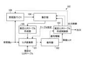
図4は、本実施形態に係る軟判定復号部のより詳細な構成例を示すブロック図である。図4に示すように、軟判定復号部182は、LLR変換部101と、復号器102と、推定LLRテーブル作成制御部103と、集計部104と、推定LLRテーブル作成部105と、受信語バッファ106とを備える。 FIG. 4 is a block diagram showing a more detailed configuration example of the soft-decision decoding unit according to this embodiment. As shown in FIG. 4 , soft
この構成において、受信語バッファ106は、受信値yの系列{y}をECCフレーム単位で記憶する。具体的には、受信語バッファ106は、不揮発性メモリ20から読み出された受信値yの系列{y}を、ECCフレーム単位で入力して記憶する。また、受信語バッファ106は、後述する推定LLRテーブル作成制御部103から、出力開始の指示や、どのECCフレームに関連する受信値yの系列{y}を出力するかを指定する情報、若しくは、ECCフレーム内の特定の受信値yを出力するかを指定する情報を入力する。そして、受信語バッファ106は、出力開始の指示に従い、現在記憶しているECCフレーム単位の受信値yのうち、指定された系列{y}又は指定された受信値yを集計部104へ出力する。 In this configuration, received
推定LLRテーブル作成制御部103は、特定の(l,y)の組から推定LLRテーブルを作成する処理を制御する。具体的には、推定LLRテーブル作成制御部103には、復号器102からの復号結果としての事後LLRの系列{l}が入力される。また、推定LLRテーブル作成制御部103には、復号に成功したか失敗したか等の復号後に得られる情報も入力される。そして、推定LLRテーブル作成制御部103は、入力された事後LLRの系列{l}に対し、外部へ出力するか、集計部104へ出力するかを判断し、判断した先へ事後LLRの系列{l}を出力する。また、推定LLRテーブル作成制御部103は、受信語バッファ106に出力開始を指示する信号、及び、集計部104を制御するための制御信号を出力する。 The estimated LLR table
集計部104は、(l,y)の組を記憶する。具体的には、集計部104は、推定LLRテーブル作成制御部103によって選定されたECCフレーム単位の事後LLRの系列{l}と、受信語バッファ106からの出力であって、推定LLRテーブル作成制御部103から入力された事後LLRの系列{l}と同じECCフレームに所属する受信値yの系列{y}とを入力する。そして、集計部104は、入力された系列{l}及び{y}から(l,y)の組を記憶する。また、集計部104は、記憶した(l,y)の組を推定LLRテーブル作成部105へ出力する。なお、集計部104には、推定LLRテーブル作成制御部103から、集計結果のリセット信号や、出力のタイミングを知らせる制御信号等も入力される。
推定LLRテーブル作成部105は、集計部104から入力された(l,y)の組から推定LLRテーブルを計算する。そして、推定LLRテーブル作成部105は、計算により得られた推定LLRテーブルをLLR変換部101へ出力する。例えば推定LLRテーブル作成部105は、以下の式(7)を用いて、推定LLRテーブルに設定するLLRの値を計算する。
S(S≧0)は、推定LLRテーブル作成の繰返し回数を表すカウント値である。l(S+1)(y)は、(S+1)回目に作成する推定LLRテーブルの受信値yに対応するLLRの値である。I(y)は、受信値がyであるシンボルの集合である。l(S)APP,iは、I(y)に含まれるシンボルiについて、指定されたLLRテーブルを用いて軟判定復号によって算出された事後LLRの値である。σはシグモイド関数である。nは、集計された(l,y)の総数である。S (S≧0) is a count value representing the number of iterations of creating the estimated LLR table. l(S+1) (y) is the LLR value corresponding to the received value y in the estimated LLR table created for the (S+1)th time. I(y) is the set of symbols whose received value is y. l(S)APP,i is the posterior LLR value calculated by soft-decision decoding using the specified LLR table for symbol i included in I(y). σ is a sigmoid function. n is the total number of (l, y) aggregated.
LLR変換部101は、推定LLRテーブル作成制御部103から指定されたLLRテーブル又は推定LLRテーブルを用いることで、不揮発性メモリ20から読み出されて入力された受信値yをLLR値に変換する。具体的には、LLR変換部101へは、不揮発性メモリ20から読み出された受信値yの系列{y}が入力される。また、LLR変換部101には、受信値yとLLR値との変換に使用される既定のLLRテーブルと、同じく受信値yとLLR値との変換に使用される推定LLRテーブル作成部105からのLLRテーブルとも入力される。さらに、LLR変換部101には、推定LLRテーブル作成制御部103から、使用するLLRテーブルの指定情報も入力される。そして、LLR変換部101は、推定LLRテーブル作成制御部103から指定されたLLRテーブルを用いて受信値yを変換することで得られたLLR値の系列を復号器102へ出力する。 The
復号器102は、ECCフレーム単位のLLR値の系列から復号に関する情報や事後LLRの系列{l}を計算する。具体的には、復号器102は、LLR変換部101からLLR値の系列を入力する。なお、復号器102には、一度の復号でECCフレームに対応する系列が入力される。そして、復号器102は、入力されたLLR値の系列を復号することで得られた事後LLRの系列{l}を推定LLRテーブル作成制御部103へ出力する。なお、復号器102は、一度の復号の結果として、ECCフレームに対応する系列{l}を出力する。また、復号器102は、復号の成否など、復号で得られた情報も推定LLRテーブル作成制御部103へ出力する。
つづいて、本実施形態に係る復号動作を、図面を参照して詳細に説明する。図5は、本実施形態に係る復号動作の概略例を示すフローチャートである。図5に示すように、本動作では、まず、メモリI/F13によって不揮発性メモリ20から読み出されたECCフレーム単位の受信値yの系列{y}が軟判定復号部182に入力される(ステップS101)。軟判定復号部182に入力された系列{y}は、受信語バッファ106に記憶されると共に、LLR変換部101に入力される。 Next, the decoding operation according to this embodiment will be described in detail with reference to the drawings. FIG. 5 is a flowchart showing a schematic example of a decoding operation according to this embodiment. As shown in FIG. 5, in this operation, first, a sequence {y} of received values y in units of ECC frames read from the
次に、例えば推定LLRテーブル作成制御部103が、推定LLRテーブル作成の繰返し回数をカウントする不図示のカウンタのカウント値Sをリセット(S=0)する(ステップS102)。つづいて、入力された受信値yの系列{y}が既定のLLRテーブルを用いて復号される(ステップS103)。具体的には、推定LLRテーブル作成制御部103が、例えばカウント値Sが0であることに基づき、入力された受信値yの系列{y}に対して使用するLLRテーブルを既定のLLRテーブルとする旨の指示をLLR変換部101に入力する。LLR変換部101は、指定された既定のLLRテーブルを用いて、受信値yの系列{y}をLLR値の系列に変換し、これにより得られたLLR値の系列を復号器102に入力する。復号器102は、入力されたLLR値の系列を復号し、その結果として得られた事後LLRの系列{l}と、復号の成否などの情報とを推定LLRテーブル作成制御部103へ出力する。なお、以下の説明では、カウント値Sのときに得られた事後LLRであるlをlSとし、lsの系列を復号系列{lS}とする。Next, for example, the estimated LLR table
次に、例えば推定LLRテーブル作成制御部103が、復号器102から入力された情報に基づいて、復号に成功したか否かを判断する(ステップS104)。復号に成功していた場合(ステップS104のYES)、本動作は、ステップS109へ進む。一方、復号に失敗していた場合(ステップS104のNO)、例えば推定LLRテーブル作成制御部103が、カウント値Sを1インクリメントする(ステップS105)。つづいて、推定LLRテーブル作成制御部103は、カウント値Sが繰返し回数の最大値S_maxより大きいか否かを判定する(ステップS106)。この最大値S_maxは、復号に成功するまで失敗した復号結果に基づく推定LLRテーブルの作成(ステップS104~S108)が繰り返されることを回避するための制限値である。カウント値Sが最大値S_maxより大きい場合(ステップS106のYES)、本動作は、ステップS111へ進む。一方、カウント値Sが最大値S_max以下である場合(ステップS106のNO)、本動作は、ステップS107へ進む。 Next, for example, the estimated LLR table
ステップS107では、ステップS103又はS108の復号により得られた事後LLRであるlSと受信値yとの組(lS,y)から、推定LLRテーブルが作成される。具体的には、集計部104が、推定LLRテーブル作成制御部103を経由して入力された事後LLRの系列{lS}と、受信語バッファ106から入力された受信値yの系列{y}とから(lS,y)の組を作成して記憶する。そして、集計部104は、(lS,y)の組を推定LLRテーブル作成部105に入力する。推定LLRテーブル作成部105は、入力された(lS,y)と、例えば上述した式(7)を用いることで、推定LLRテーブルを作成する。作成した推定LLRテーブルは、LLR変換部101へ入力される。In step S107, an estimated LLR table is created from a set (lS , y) of lS which is the posterior LLR obtained by the decoding in step S103 or S108 and the received value y. Specifically, totaling
次に、受信値yの系列{y}が推定LLRテーブルを用いて復号される(ステップS108)。具体的には、推定LLRテーブル作成制御部103が、例えば非零のカウント値Sに基づき、受信値yの系列{y}に対して使用するLLRテーブルを新たに作成された推定LLRテーブルとする旨の指示をLLR変換部101に入力する。LLR変換部101は、指定された推定LLRテーブルを用いて、受信値yの系列{y}をLLR値の系列に変換し、これにより得られたLLR値の系列を復号器102に入力する。復号器102は、入力されたLLR値の系列を復号し、その結果として得られた事後LLRの系列{lS}と、復号の成否などの情報とを推定LLRテーブル作成制御部103へ出力する。その後、本動作は、ステップS104へリターンする。Next, the sequence {y} of received values y is decoded using the estimated LLR table (step S108). Specifically, the estimated LLR table
ステップS109、すなわち、ステップS103又はS108の復号に成功していた場合(ステップS104のYES)、復号成功が例えば推定LLRテーブル作成制御部103から制御部11(図1参照)へ通知される。また、推定LLRテーブル作成制御部103からは、復号により得られた事後LLRの系列{lS}から生成される推定値kSの復号系列{kS}も出力される(ステップS110)。その後、本動作が終了する。なお、出力された復号系列{kS}は、例えば、データバッファ12(図1参照)に蓄積され、書込み値であるユーザデータに復元された後、読出し要求を発行したホスト30へ送信される。In step S109, that is, when the decoding in step S103 or S108 has succeeded (YES in step S104), the estimated LLR table
また、ステップS111、すなわち、カウント値Sが最大値S_maxに達するまで推定LLRテーブルの作成を繰り返しても復号に成功しなかった場合(ステップS106のYES)には、復号失敗が例えば推定LLRテーブル作成制御部103から制御部11(図1参照)へ通知され、本動作が終了する。これに対し、制御部11は、例えば、要求されたデータの読出しエラーを読出し要求を発行したホスト30へ送信する。 Further, in step S111, that is, when the generation of the estimated LLR table is repeated until the count value S reaches the maximum value S_max, the decryption does not succeed (YES in step S106). The
以上のように、本実施形態では、推定値kではなく、事後LLRを用いてLLRテーブルを作成する。これにより、LLRテーブルをより効率的に推定することができる。例えば、推定値kを用いる方法では、初期値として使用したLLRテーブルと真のLLRテーブルとの不一致が大きいと、推定回数を増やしても真のLLRテーブルの性能に近づくことができない場合がある。これに対して本実施形態では、初期値として使用したLLRテーブルと真のLLRテーブルとの不一致が大きい場合であっても、真のLLRテーブルにより近い推定LLRテーブルを作成することが可能となる。これは、本実施形態で推定LLRテーブルを作成する処理が、EM(Expectation Maximization)アルゴリズムに従ってLLRテーブルを推定する処理に相当すると解釈できるためである。以下、この解釈の詳細について説明する。 As described above, in this embodiment, the LLR table is created using the posterior LLR instead of the estimated value k. This allows the LLR table to be estimated more efficiently. For example, in the method using the estimated value k, if there is a large discrepancy between the LLR table used as the initial value and the true LLR table, even if the number of estimations is increased, the performance of the true LLR table may not be approached. On the other hand, in this embodiment, even if the LLR table used as the initial value and the true LLR table have a large discrepancy, it is possible to create an estimated LLR table closer to the true LLR table. This is because the process of creating the estimated LLR table in this embodiment can be interpreted as equivalent to the process of estimating the LLR table according to the EM (Expectation Maximization) algorithm. The details of this interpretation are described below.
まず、EMアルゴリズムの概要について説明する。 First, an outline of the EM algorithm will be explained.
手元にある定まったデータを観測変数、データが不完全であるために様々な値を取る可能性がある確率変数を潜在変数と呼ぶ。EMアルゴリズムは、不完全データ集合の最尤推定を目的とする逐次的なアルゴリズムである。逐次的な更新のたびに、不完全データの対数尤度が増加する方向にパラメータが変化することが示されている。具体的な手順は以下のようになる。
(A1)パラメータεの初期値を選ぶ。
(A2)E(Expectation)ステップ:現在のパラメータεと観測変数を条件とした潜在変数の事後確率を求める。
(A3)M(Maximization)ステップ:Eステップで得られた潜在変数の事後確率を用いて、観測変数だけでなく潜在変数も定まっている完全データ集合の対数尤度の期待値を最大化するパラメータεnewを計算する。
(A4)終了条件を満たしていない場合、ε=εnewとしてEステップに戻る。The fixed data at hand is called an observed variable, and the random variable that can take various values due to incomplete data is called a latent variable. The EM algorithm is an iterative algorithm aimed at maximum likelihood estimation of incomplete datasets. It is shown that with each successive update, the parameters change in the direction that increases the log-likelihood of incomplete data. The specific procedure is as follows.
(A1) Choose an initial value for the parameter ε.
(A2) E (Expectation) step: find the posterior probability of the latent variable under the conditions of the current parameter ε and the observed variable.
(A3) M (Maximization) step: A parameter that maximizes the expected value of the logarithmic likelihood of the complete data set in which not only the observed variable but also the latent variable are determined using the posterior probability of the latent variable obtained in the E step. Compute εnew .
(A4) If the end condition is not satisfied, return to step E with ε=εnew .
本実施形態は、EMアルゴリズムを、真のLLRテーブルが不明な場合に符号語を求める問題に適用したと解釈することができる。正解の符号語が潜在変数であり、観測変数は受信語であり、パラメータはLLRテーブルである。また、符号語の事後確率を計算できる復号器を使用できるとする。この場合、LLRテーブルを推定する処理は、以下のような手順となる。正解の符号語を求めることが目的であるため、復号が成功した時点で以下の手順は終了する。
(B1)LLRテーブル(初期値)を仮定する。
(B2)Eステップ:現在のLLRテーブルで事後確率を求める復号を実施し、符号語の事後確率を求める。復号が成功したら推定符号語を出力して終了する。
(B3)Mステップ:Eステップで得られた符号語の事後確率を用いて、符号語と受信語の組(完全データ集合)の対数尤度の期待値を最大化するLLRテーブルを計算する。LLRテーブルが更新されている場合、Eステップに戻る。This embodiment can be interpreted as applying the EM algorithm to the problem of finding codewords when the true LLR table is unknown. The correct codeword is the latent variable, the observed variable is the received word, and the parameter is the LLR table. We also assume that a decoder is available that can compute the posterior probabilities of the codewords. In this case, the process of estimating the LLR table has the following procedure. Since the purpose is to obtain the correct codeword, the following procedure ends when the decoding is successful.
(B1) Assume an LLR table (initial value).
(B2) Step E: Perform decoding for obtaining posterior probabilities with the current LLR table to obtain posterior probabilities of codewords. If the decoding is successful, output the estimated codeword and terminate.
(B3) M step: Using the codeword posterior probability obtained in E step, calculate an LLR table that maximizes the expected value of the logarithmic likelihood of the codeword-received word pair (complete data set). If the LLR table has been updated, return to step E.
一般には、符号語の事後確率を正確に計算することは難しい。しかし、通信路が無記憶通信路である場合は、符号語全体の事後確率を、構成要素であるシンボルごとに周辺化して得られる事後確率(シンボルごとの事後確率)で置き換えることができる。この理由については後述する。 In general, it is difficult to accurately compute the posterior probability of a codeword. However, if the communication channel is a memoryless channel, the posterior probability of the entire codeword can be replaced by the posterior probability obtained by marginalizing each symbol (symbol-by-symbol posterior probability). The reason for this will be described later.
シンボルごとの事後確率は、ループを含まないグラフ構造で特徴づけられる符号を使用する場合であれば、例えば確率伝搬復号(Belief Propagation復号、BP復号)で効率的に計算できる。一般に使用される符号はループを含むグラフ構造を有するが、その場合でも良い近似で計算できることが知られている。無記憶通信路を想定し、BP復号を用いる場合の処理は、以下のような手順となる。
(C1)LLRテーブル(初期値)を仮定する。
(C2)Eステップ:現在のLLRテーブルでBP復号を実施し、符号語の事後確率(シンボルごとの事後確率)を求める。復号が成功したら推定符号語を出力して終了する。
(C3)Mステップ:Eステップで得られたシンボルごとの事後確率を用いて、符号語と受信語の対数尤度の期待値を最大化するLLRテーブルを計算する。LLRテーブルが更新されている場合、Eステップに戻る。The posterior probabilities for each symbol can be efficiently computed, for example, by Belief Propagation decoding (BP decoding) if a code characterized by a loop-free graph structure is used. Although commonly used codes have a graph structure including loops, it is known that good approximations can be calculated even in such cases. Assuming a memoryless communication channel, the processing in the case of using BP decoding is as follows.
(C1) Assume an LLR table (initial value).
(C2) E step: BP decoding is performed with the current LLR table to obtain the posterior probability of the codeword (posterior probability for each symbol). If the decoding is successful, output the estimated codeword and terminate.
(C3) M step: Using the posterior probability for each symbol obtained in the E step, calculate an LLR table that maximizes the expected value of the log-likelihood of the codeword and received word. If the LLR table has been updated, return to step E.
無記憶通信路である場合に加えて、シンボルごとの通信路が多項分布であり、シンボルによってパラメータが変化しない場合を考える。この場合の処理は、以下のような手順となる。
(D1)LLRテーブル(初期値)を仮定する。
(D2)Eステップ:現在のLLRテーブルでBP復号を実施し、符号語の事後確率(シンボルごとの事後確率)を求める。復号が成功したら推定符号語を出力して終了する。
(D3)Mステップ:Eステップで得られたi番目のシンボルxiごとの事後確率pBP(xi)と、対応する受信値yi=kと、の組を用いて、受信値kに与える新たなLLR値を以下の式(8)に従い計算する。LLRテーブルが更新されている場合、Eステップに戻る。
(D1) Assume an LLR table (initial value).
(D2) Step E: Perform BP decoding with the current LLR table to obtain the posterior probability of the codeword (posterior probability for each symbol). If the decoding is successful, output the estimated codeword and terminate.
(D3) M step: Using the set of the posterior probability pBP (xi ) for each i-th symbol xi obtained in the E step and the corresponding received value yi =k, to the received value k A given new LLR value is calculated according to the following equation (8). If the LLR table has been updated, return to step E.
シンボルごとの通信路が多項分布の場合に、対数尤度の期待値を最大化するLLR値が式(8)で表される理由について以下に説明する。図6は、多項分布で表した各シンボルの通信路の一例を示す図である。εxyは、書込み値xが与えられたときに受信値yが得られる条件付き確率P(y|x)、すなわち、尤度に相当する。以下では、εxyを遷移確率という場合がある。図6ではi番目のシンボルの例を記載しているが、iによって遷移確率εは影響しないと仮定している。図6の例では、送信シンボル(送信値xi)は0および1であり、受信値yiは1からKである。The reason why the LLR value that maximizes the expected value of the log-likelihood is represented by Equation (8) when the channel for each symbol has a multinomial distribution will be described below. FIG. 6 is a diagram showing an example of a communication path for each symbol represented by a multinomial distribution. εxy corresponds to the conditional probability P(y|x) of obtaining the received value y when the written value x is given, that is, the likelihood. Below, εxy may be referred to as a transition probability. FIG. 6 describes an example of the i-th symbol, but it is assumed that i does not affect the transition probability ε. In the example of FIG. 6, the transmitted symbols (transmitted values xi ) are 0 and 1 and the received values yi are 1-K.
遷移確率εをパラメータとし、以下の式(9)に示す規格化条件の下で、符号語と受信語の対数尤度の期待値を最大化する新たなパラメータεxyを計算する。パラメータεxyは、以下の式(10)により計算される。

パラメータεxyは、尤度(遷移確率)であるため、対数尤度比(LLR)は以下の式(11)で表すことができる。式(10)および式(11)から、式(8)が得られる。
事後LLRの定義から、事後確率pBPは、シグモイド関数σを用いて、以下の式(12)ように表すことができる。式(12)を式(8)に代入すると、式(7)が得られる。なお、事後値として事後確率を用いる場合、推定LLRテーブル作成部105は、式(7)の代わりに例えば式(8)を用いて推定LLRテーブルに設定するLLRの値を計算することができる。
次に、無記憶通信路を想定した場合に、符号語の事後確率ではなくシンボルごとの事後確率でEMアルゴリズムに必要な計算が可能である理由について説明する。 Next, assuming a memoryless channel, the reason why the posterior probabilities for each symbol rather than the posterior probabilities of the codewords can be used for the calculation required for the EM algorithm will be explained.
無記憶通信路を考え、シンボルごとの通信路を特徴づけるパラメータをε、使用している符号を特徴づける検査行列をHとする。検査行列Hは固定であるものとする。完全データ集合の事後確率は、シンボルごとの積に分解できる。すなわち、送信語をx、受信語をyとしたとき、完全データ集合の事後確率は、以下の式(13)で表すことができる。
Mステップで最大化する期待値は、以下の式(14)で計算される。
例えばln p(y1|x1,ε)の項を計算すると、符号語(x1,・・・,xn)の事後確率をx1以外の変数で周辺化した事後確率が表れる。この事後確率はBP復号によって効率的に計算できる。例えばLDPC符号であれば、sum-product復号法を用いると、検査行列がサイクルを含んでいなければ符号長に線形な計算量で正確に計算可能である。サイクルを含む場合でも、良い近似で計算できることが知られている。近似的なBP復号を実行できる符号でも、事後確率は近似的に計算できる。正確な事後確率が計算できない場合でも、近似的に求めた事後確率をpBP(x1)として、以下の式(15)のように表すことができる。
この結果、最終的に最大化する期待値は以下の式(16)で表すことができる。式(16)に示すように、期待値の計算は、符号長の指数のサイズを持つ符号語の全てのパターンを加算(式(14))から、符号長の線形な加算(式(16))になる。式(16)のp(yi|xi,ε)として図6で定義される多項分布を代入し、式(9)の条件の下でεxyを最大化すると式(10)が得られ、その結果を対数尤度比の定義に代入すると式(8)が得られる。
(変形例1)
なお、推定LLRテーブル作成部105は、不揮発性メモリに記憶された送信値の偏りを補正するように、新たなLLR値を計算してもよい。例えば推定LLRテーブル作成部105は、符号化で生成されるパリティは式(7)のままで、偏りが与えられた符号化対象の複数のシンボルに対しては以下の式(17)を用いて、推定LLRテーブルに設定するLLRの値を計算してもよい。psは、偏り抑制符号化により得られるシンボルの偏り確率を表す。例えばps(x=0)は、xが0である確率を表し、ps(x=1)は、xが1である確率を表す。偏り抑制符号化としては、例えばアシンメトリック・コーディング(Asymmetric Coding)を用いることができる。psを含む項が、不揮発性メモリに記憶された送信値の偏りを補正するための値に相当する。
Note that the estimated LLR
(変形例2)
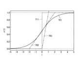
式(7)および式(17)などでは、シグモイド関数が用いられているが、少なくとも3つの入力値に対する出力値が単調増加する関数であれば、シグモイド関数の代わりに他の関数が用いられてもよい。図7は、シグモイド関数、および、シグモイド関数以外の関数の例を示す図である。関数701、関数702、703は、少なくとも3つの入力値に対する出力値が単調増加する関数の例である。関数701は、シグモイド関数である。関数702は、lが-2から2の間で単調増加する線形関数を含む関数である。関数703は、lが0より大きい場合に単調増加する線形関数を含む関数である。(Modification 2)
Although the sigmoid function is used in the formulas (7) and (17), other functions may be used instead of the sigmoid function as long as the output value for at least three input values increases monotonically. good too. FIG. 7 is a diagram showing examples of a sigmoid function and functions other than the sigmoid function.
なお、関数711は、lが0のときにステップ状に値が増加するステップ関数であるため、少なくとも3つの入力値に対する出力値が単調増加する関数には相当しない。また、関数711を用いて事後LLR(l(S)APP,i)を変換した値は、推定値kに相当する。従って、シグモイド関数の代わりに関数711を用いる構成は、推定値kによりLLRテーブルを作成する構成に相当することになる。Note that the
以上のように、本実施形態では、復号に失敗した場合でも、この失敗した復号により得られた事後LLRの系列{l}を使用して、推定LLRテーブルの作成を1回以上実行する。これにより、推定する通信路を正しい通信路に近づけることが可能になる。その結果、通信路の不一致に基づく復号失敗を救済できる可能性が高まるため、通信路の不一致に基づく復号特性の劣化を抑えることが可能なメモリシステムを実現することができる。 As described above, in this embodiment, even if decoding fails, the posterior LLR sequence {l} obtained by this failed decoding is used to create an estimated LLR table one or more times. This makes it possible to bring the estimated communication channel closer to the correct communication channel. As a result, the possibility of relieving decoding failures due to mismatching of communication channels increases, so that it is possible to realize a memory system capable of suppressing degradation of decoding characteristics due to mismatching of communication channels.
(第2の実施形態)
次に、第2の実施形態に係るメモリシステムについて、図面を参照して詳細に説明する。なお、以下の説明において、第1の実施形態と同様の構成及び動作については、それを引用することで、重複する説明を省略する。(Second embodiment)
Next, a memory system according to the second embodiment will be described in detail with reference to the drawings. In the following description, the same configuration and operation as those of the first embodiment will be referred to, and redundant description will be omitted.
第1の実施形態は、失敗した復号結果に基づいて推定LLRテーブルを作成する動作を1回以上繰り返すことで、推定する通信路を正しい通信路に近づける構成を備えていた。これに対し、第2の実施形態は、第1の実施形態と同様にして作成された推定LLRテーブルをさらに補正する構成を備える。 The first embodiment has a configuration in which an estimated communication channel is brought closer to a correct communication channel by repeating the operation of creating an estimated LLR table based on a failed decoding result one or more times. In contrast, the second embodiment has a configuration for further correcting the estimated LLR table created in the same manner as in the first embodiment.
本実施形態に係るメモリシステムは、第1の実施形態において図1を用いて説明したメモリシステム1と同様の構成を備えてよい。ただし、本実施形態では、図4における軟判定復号部182が図8に示す軟判定復号部282に置き換えられる。 The memory system according to this embodiment may have the same configuration as the
図8に示すように、本実施形態に係る軟判定復号部282は、図4に示す軟判定復号部182と同様の構成に加え、推定LLRテーブル補正部201をさらに備える。推定LLRテーブル補正部201は、例えば推定LLRテーブル作成制御部103からの指示に従い、推定LLRテーブル作成部105で作成された推定LLRテーブルを補正し、補正後の推定LLRテーブルをLLR変換部101に入力する。 As shown in FIG. 8, the soft-
ここで、推定LLRテーブル補正部201が実行する補正の一例について説明する。図9は、不揮発性メモリ20を構成する各メモリセルが1ビットのデータを記憶するシングルレベルセル(SLC)である場合の閾値電圧分布と読出し電圧との関係を示す模式図である。図9において、Er分布は、例えば‘1’のデータが書き込まれたメモリセルの閾値電圧の分布を示し、A分布は、例えば‘0’のデータが書き込まれたメモリセルの閾値電圧の分布を示している。また、Vr1~Vr7は、メモリセルからデータを読み出す際に使用する読出し電圧(以下、リードレベルという)の例を示している。なお、Vr1~Vr7のうち、Vr4は、硬判定読出し(ハードビットリード)の際に使用するリードレベルの例を示し、Vr1~Vr3及びVr5~Vr7は、軟判定読出(ソフトビットリード)の際に使用するリードレベルの例を示している。ただし、ソフトビットリードの際に使用されるリードレベルには、Vr4が含まれてもよい。 Here, an example of correction performed by the estimated LLR
このような閾値電圧分布に対し、メモリセルの閾値電圧が例えばEr分布のピーク付近の電圧である場合、そのメモリセルが記憶するデータの値は‘1’である可能性が高い。同様に、メモリセルの閾値電圧が例えばA分布のピーク付近の電圧である場合、そのメモリセルが記憶するデータの値は‘0’である可能性が高い。そこで、このような場合に推定LLRテーブル補正部201が実行する補正の一例としては、読出しデータからメモリセルの閾値電圧がいずれかの分布のピーク付近にあると認められる場合には、その分布に対応する値である確率が高いとして、そのLLR値の絶対値が高い値となるように補正する。 With respect to such a threshold voltage distribution, if the threshold voltage of a memory cell is, for example, a voltage near the peak of the Er distribution, the value of data stored in that memory cell is highly likely to be '1'. Similarly, if the threshold voltage of a memory cell is, for example, a voltage near the peak of the A distribution, the data value stored in that memory cell is likely to be '0'. Therefore, as an example of correction performed by the estimated LLR
また、メモリセルの閾値電圧が例えばEr分布とA分布との境界付近の電圧である場合、そのメモリセルが記憶するデータの値が‘1’である可能性と‘0’である可能性とはほぼ同等である。そこで、このような場合に推定LLRテーブル補正部201が実行する補正の一例としては、読出しデータからメモリセルの閾値電圧が隣接する分布の境界付近にあると認められる場合には、いずれの分布に対応する値であるかが不確定であるとして、そのLLR値の絶対値が低い値となるように補正する。その際、LLR値の正負が反転してもよい。 Further, when the threshold voltage of a memory cell is, for example, a voltage near the boundary between the Er distribution and the A distribution, the data value stored in the memory cell may be '1' or '0'. are almost equivalent. Therefore, as an example of correction performed by the estimated LLR
なお、補正の方法としては、LLR値の絶対値を固定値とする方法や、LLR値の絶対値に対して所定の値を加算又は減算する方法など、種々の方法を適用することが可能である。 As a correction method, various methods can be applied, such as a method of fixing the absolute value of the LLR value, a method of adding or subtracting a predetermined value from the absolute value of the LLR value, and the like. be.
つづいて、本実施形態に係る復号動作を、図面を参照して詳細に説明する。図10は、本実施形態に係る復号動作の概略例を示すフローチャートである。図10に示すように、本実施形態に係る復号動作は、図5に示した第1の実施形態に係る復号動作と同様の動作において、ステップS108がステップS201~S202に置き換えられている。 Next, the decoding operation according to this embodiment will be described in detail with reference to the drawings. FIG. 10 is a flowchart showing a schematic example of the decoding operation according to this embodiment. As shown in FIG. 10, the decoding operation according to this embodiment is similar to the decoding operation according to the first embodiment shown in FIG. 5, except that step S108 is replaced with steps S201 and S202.
すなわち、本実施形態では、ステップS103又はS202の復号により得られた事後LLRであるlSと受信値yとの組(lS,y)から推定LLRテーブルを作成すると(ステップS107)、作成した推定LLRテーブルが補正される(ステップS201)。具体的には、推定LLRテーブル作成部105によって作成された推定LLRテーブルが推定LLRテーブル補正部201に入力されると、推定LLRテーブル補正部201は、推定LLRテーブル作成制御部103から入力された補正情報に基づいて推定LLRテーブルを補正し、補正後の推定LLRテーブルをLLR変換部101に入力する。That is, in the present embodiment, when an estimated LLR table is created from the set (lS , y) of the received value y and lS which is the posterior LLR obtained by decoding in step S103 or S202 (step S107), the created The estimated LLR table is corrected (step S201). Specifically, when the estimated LLR table created by the estimated LLR
次に、受信値yの系列{y}が補正後の推定LLRテーブルを用いて復号される(ステップS202)。具体的には、推定LLRテーブル作成制御部103が、例えば非零のカウント値Sに基づき、受信値yの系列{y}に対して使用するLLRテーブルを新たに作成されて補正された推定LLRテーブルとする旨の指示をLLR変換部101に入力する。LLR変換部101は、指定された補正後の推定LLRテーブルを用いて、受信値yの系列{y}をLLR値の系列に変換し、これにより得られたLLR値の系列を復号器102に入力する。復号器102は、入力されたLLR値の系列を復号し、その結果として得られた事後LLRの系列{lS}と、復号の成否などの情報とを推定LLRテーブル作成制御部103へ出力する。Next, the sequence {y} of received values y is decoded using the corrected estimated LLR table (step S202). Specifically, estimated LLR table
以上のように、本実施形態では、失敗した復号結果に基づいて作成された推定LLRテーブルを補正する構成を備える。それにより、本実施形態では、ストレスにとって補正が適切であれば、より安定して復号に成功するように推定LLRテーブルを補正することが可能となる。 As described above, this embodiment has a configuration for correcting an estimated LLR table created based on a failed decoding result. Accordingly, in this embodiment, if the correction is appropriate for the stress, it is possible to correct the estimated LLR table so that the decoding is more stable and successful.
なお、その他の構成、動作及び効果は、上述した実施形態と同様であるため、ここでは詳細な説明を省略する。 Since other configurations, operations and effects are the same as those of the above-described embodiment, detailed description thereof is omitted here.
(第3の実施形態)
次に、第3の実施形態に係るメモリシステムについて、図面を参照して詳細に説明する。なお、以下の説明において、第1又は第2の実施形態と同様の構成及び動作については、それを引用することで、重複する説明を省略する。(Third embodiment)
Next, a memory system according to the third embodiment will be described in detail with reference to the drawings. It should be noted that in the following description, configurations and operations that are the same as those of the first or second embodiment will be referred to, and redundant description will be omitted.
上述した第1又は第2の実施形態では、1つのECCフレームの復号結果に基づいて推定LLRテーブルを作成する場合を例示した。これに対し、第3の実施形態では、複数(所定数)のECCフレームの復号結果に基づいて推定LLRテーブルを作成する場合を例示する。 In the first or second embodiment described above, the case of creating an estimated LLR table based on the decoding result of one ECC frame has been exemplified. On the other hand, in the third embodiment, a case will be illustrated in which an estimated LLR table is created based on the decoding results of a plurality (predetermined number) of ECC frames.
同じような雑音の影響を受けることが想定される通信路であれば、それらの通信路から得られる条件付き確率P(y|x)は同様のものとなる。そこで本実施形態では、同様の通信路で雑音の影響を受けると思われる複数のECCフレームを一括で処理できる場合に、その全てのECCフレームの集計結果から推定LLRテーブルを作成する。それにより、推定LLRテーブルの作成に使用する(l,y)の組の数を増加させることが可能となるため、推定する通信路をより真の通信路に近づけることが可能となる。なお、同じような雑音の影響を受けることが想定される通信路としては、同一又は隣接するワードラインに書き込まれたECCフレームなどが想定されるが、これに限定されるものではない。 If communication paths are assumed to be affected by similar noise, the conditional probabilities P(y|x) obtained from those communication paths will be similar. Therefore, in the present embodiment, when a plurality of ECC frames that are considered to be affected by noise on a similar communication channel can be processed collectively, an estimated LLR table is created from the aggregate results of all the ECC frames. As a result, it is possible to increase the number of (l, y) pairs used to create the estimated LLR table, so that the estimated communication channel can be brought closer to the true communication channel. As a communication path that is assumed to be affected by similar noise, an ECC frame written in the same or adjacent word line is assumed, but it is not limited to this.
本実施形態に係るメモリシステム及びその復号部の構成は、例えば上述した第1又は第2の実施形態に係るメモリシステム1及びその軟判定復号部182又は282と同様であってよい。ただし、本実施形態では、軟判定復号部182又は282が、複数のECCフレームを一括に処理できるように構成され、復号器102には、複数のECCフレームが入力され、受信語バッファ106には、複数のECCフレームが記憶される。 The configuration of the memory system and its decoding section according to this embodiment may be the same as the
つづいて、本実施形態に係る復号動作を、図面を参照して詳細に説明する。なお、以下の説明では、第2の実施形態において例示した復号動作(図10参照)をベースとするが、これに限定されず、第1の実施形態において例示した復号動作(図5参照)をベースとするなど、種々変形することが可能である。 Next, the decoding operation according to this embodiment will be described in detail with reference to the drawings. Note that the following description is based on the decoding operation (see FIG. 10) exemplified in the second embodiment, but is not limited thereto, and the decoding operation (see FIG. 5) exemplified in the first embodiment is used as a base. Various modifications such as using it as a base are possible.
図11は、本実施形態に係る復号動作の概略例を示すフローチャートである。図11に示すように、本実施形態に係る復号動作は、図10に示した第2の実施形態に係る復号動作と同様の動作において、ステップS101、S104、S107及びS202がそれぞれステップS301、S302、S303及びS304に置き換えられている。 FIG. 11 is a flow chart showing a schematic example of a decoding operation according to this embodiment. As shown in FIG. 11, the decoding operation according to this embodiment is similar to the decoding operation according to the second embodiment shown in FIG. , S303 and S304.
すなわち、本実施形態では、まず、メモリI/F13によって不揮発性メモリ20から読み出された複数のECCフレームの系列{y}が軟判定復号部282に入力される(ステップS301)。軟判定復号部282に入力された複数のECCフレームの系列{y}は、受信語バッファ106に記憶されると共に、LLR変換部101に入力される。 That is, in this embodiment, first, a sequence {y} of a plurality of ECC frames read from the
次に、カウント値Sをリセット(S=0)した後(ステップS102)、入力された複数のECCフレームの系列{y}が既定のLLRテーブルを用いて復号される(ステップS103)。なお、個々のECCフレームの系列{y}に対する復号は、上述した実施形態と同様であってよい。 Next, after resetting the count value S (S=0) (step S102), the input sequence {y} of a plurality of ECC frames is decoded using the default LLR table (step S103). It should be noted that the decoding for each sequence {y} of ECC frames may be the same as in the above-described embodiment.
次に、例えば推定LLRテーブル作成制御部103が、復号器102から入力された情報に基づいて、全てのECCフレームに対する復号に成功したか否かを判断する(ステップS302)。全てのECCフレームに対する復号に成功していた場合(ステップS302のYES)、本動作は、ステップS109へ進み、以降の動作を実行する。一方、復号に失敗したECCフレームが存在する場合(ステップS302のNO)、カウント値Sが1インクリメントされ(ステップS105)、インクリメント後のカウント値Sが最大値S_maxより大きいか否かが判定される(ステップS106)。その後、カウント値Sが最大値S_maxより大きい場合(ステップS106のYES)、本動作は、ステップS111へ進み、以降の動作を実行する。一方、カウント値Sが最大値S_max以下である場合(ステップS106のNO)、本動作は、ステップS303へ進む。 Next, for example, the estimated LLR table
ステップS303では、ステップS103又はS304の復号により得られた事後LLRであるlSのうち、同様のストレスを受けた1つ以上のECCフレームのlSの系列{lS}と受信値yとの組(lS,y)から、推定LLRテーブルが作成される。具体的には、集計部104が、推定LLRテーブル作成制御部103を経由して入力された複数のECCフレームのうち、同様のストレスを受けていると想定される1つ以上のECCフレームを特定する。つづいて、集計部104は、特定した1つ以上のECCフレームそれぞれのlSの系列{lS}と、受信語バッファ106から入力された受信値yの系列{y}とから(lS,y)の組を作成して記憶する。そして、集計部104は、現在記憶されている(lS,y)を推定LLRテーブル作成部105に入力する。推定LLRテーブル作成部105は、入力された(lS,y)の組と、例えば上述した式(7)を用いることで、推定LLRテーブルを作成する。作成した推定LLRテーブルは、推定LLRテーブル補正部201に入力されて補正される(ステップS201)。In step S303, among lS that are the posterior LLRs obtained by the decoding in step S103 or S304, the lS sequence {lS } of one or more ECC frames subjected to the same stress and the received value y From the tuple (lS , y), an estimated LLR table is constructed. Specifically, the
次に、全てのECCフレームのうち、未だ復号に成功していないECCフレームの受信値yの系列{y}が補正後の推定LLRテーブルを用いて復号される(ステップS304)。なお、個々のECCフレームの系列{y}に対する復号は、上述した実施形態と同様であってよい。その後、本動作は、ステップS302へリターンする。 Next, among all the ECC frames, the sequence {y} of the received values y of the ECC frames that have not yet been successfully decoded is decoded using the corrected estimated LLR table (step S304). It should be noted that the decoding for each sequence {y} of ECC frames may be the same as in the above-described embodiment. After that, the operation returns to step S302.
以上のように、本実施形態では、同様の通信路で雑音の影響を受けると思われる複数のECCフレームを一括で処理できる場合に、その全てのECCフレームの集計結果から推定LLRテーブルを作成する。それにより、推定LLRテーブルの作成に使用する(l,y)の組の数を増加させることが可能となるため、推定する通信路をより真の通信路に近づけることが可能となる。 As described above, in the present embodiment, when a plurality of ECC frames that are considered to be affected by noise in the same communication channel can be processed collectively, an estimated LLR table is created from the aggregate results of all the ECC frames. . As a result, it is possible to increase the number of (l, y) pairs used to create the estimated LLR table, so that the estimated communication channel can be brought closer to the true communication channel.
なお、その他の構成、動作及び効果は、上述した実施形態と同様であるため、ここでは詳細な説明を省略する。 Since other configurations, operations and effects are the same as those of the above-described embodiment, detailed description thereof is omitted here.
本発明のいくつかの実施形態を説明したが、これらの実施形態は、例として提示したものであり、発明の範囲を限定することは意図していない。これら新規な実施形態は、その他の様々な形態で実施されることが可能であり、発明の要旨を逸脱しない範囲で、種々の省略、置き換え、変更を行うことができる。これら実施形態やその変形は、発明の範囲や要旨に含まれるとともに、特許請求の範囲に記載された発明とその均等の範囲に含まれる。 While several embodiments of the invention have been described, these embodiments have been presented by way of example and are not intended to limit the scope of the invention. These novel embodiments can be implemented in various other forms, and various omissions, replacements, and modifications can be made without departing from the scope of the invention. These embodiments and modifications thereof are included in the scope and gist of the invention, and are included in the scope of the invention described in the claims and equivalents thereof.
1 メモリシステム
10 メモリコントローラ
11 制御部
12 データバッファ
13 メモリI/F
14 符号化/復号部
15 ホストI/F
16 内部バス
17 符号化部
18 復号部
20 不揮発性メモリ
30 ホスト
101 LLR変換部
102 復号器
103 推定LLRテーブル作成制御部
104 集計部
105 推定LLRテーブル作成部
106 受信語バッファ
201 推定LLRテーブル補正部
181 硬判定復号部
182、282 軟判定復号部1
14 Encoding/
16
Claims (7)
Translated fromJapanese前記不揮発性メモリから読み出された受信値を、第1変換テーブルを用いて第1尤度情報に変換し、
前記第1尤度情報に対して復号を実行して事後値を出力し、
前記復号に成功した場合、前記事後値に基づいて得られる、前記受信値の推定値を出力し、
前記復号に失敗した場合、前記事後値に基づいて、第2変換テーブルを作成し、
前記第2変換テーブルを作成した場合、前記第2変換テーブルを用いて前記受信値を第2尤度情報に変換し、
前記第2尤度情報に対して復号を実行して事後値を出力する、
メモリコントローラと、を備え、
前記メモリコントローラは、
少なくとも3つの入力値に対する出力値が単調増加する関数に対して前記事後値を入力して得られる値を用いて、前記受信値に対応する尤度情報を算出し、前記受信値と、前記算出された尤度情報とを対応づけた前記第2変換テーブルを作成する、
メモリシステム。non-volatile memory;
converting the received value read from the nonvolatile memory into first likelihood information using a first conversion table;
performing decoding on the first likelihood information and outputting a posterior value;
if the decoding is successful, outputting an estimate of the received value obtained based on the post value;
if the decoding fails, create a second conversion table based on the post value;
when the second conversion table is created, converting the received value into second likelihood information using the second conversion table;
performing decoding on the second likelihood information and outputting a posterior value;
a memory controller;
The memory controller
calculating likelihood information corresponding to the received value using a value obtained by inputting the post-value to a function in which output values for at least three input values monotonically increase; creating the second conversion table in association with the calculated likelihood information;
memory system.
請求項1に記載のメモリシステム。the function is a sigmoid function,
2. The memory system ofclaim 1 .
請求項1に記載のメモリシステム。The function is a function comprising a monotonically increasing linear function,
2. The memory system ofclaim 1 .
前記関数に対して前記事後値を入力して得られる値、および、前記不揮発性メモリに記憶された送信値の偏りを補正するための値を用いて、前記受信値に対応する尤度情報を算出し、前記受信値と、前記算出された尤度情報とを対応づけた前記第2変換テーブルを作成する、
請求項1に記載のメモリシステム。The memory controller
likelihood information corresponding to the received value using a value obtained by inputting the post-value to the function and a value for correcting bias of the transmitted value stored in the non-volatile memory; and creating the second conversion table that associates the received value with the calculated likelihood information.
2. The memory system ofclaim 1 .
前記第2尤度情報の復号に失敗する度に、前記失敗した復号により得られた事後値に基づいて新たな第2変換テーブルを作成し、
前記第2変換テーブルを作成する度に、前記新たに作成された第2変換テーブルを用いて前記受信値を前記第2尤度情報に変換し、
前記受信値を前記第2尤度情報に変換する度に、前記第2尤度情報を復号する、
請求項1に記載のメモリシステム。The memory controller
each time decoding of the second likelihood information fails, creating a new second conversion table based on the posterior value obtained by the failed decoding;
Each time the second conversion table is created, the received value is converted into the second likelihood information using the newly created second conversion table;
decoding the second likelihood information each time the received value is converted to the second likelihood information;
2. The memory system of claim 1.
作成した前記第2変換テーブルを補正し、
補正後の前記第2変換テーブルを用いて前記受信値を前記第2尤度情報に変換する、
請求項1に記載のメモリシステム。The memory controller
Correcting the created second conversion table,
converting the received value into the second likelihood information using the corrected second conversion table;
2. The memory system of claim 1.
所定数の前記受信値で構成された受信値系列を単位として、前記受信値系列を前記所定数の前記第1尤度情報又は前記第2尤度情報で構成された尤度情報系列に変換し、
前記尤度情報系列を単位として前記復号を実行する、
請求項1に記載のメモリシステム。The memory controller
converting the received value sequence into a likelihood information sequence composed of the predetermined number of the first likelihood information or the second likelihood information, using a received value sequence composed of a predetermined number of the received values as a unit; ,
performing the decoding in units of the likelihood information series;
2. The memory system of claim 1.
Priority Applications (2)
| Application Number | Priority Date | Filing Date | Title |
|---|---|---|---|
| JP2019170681AJP7309551B2 (en) | 2019-09-19 | 2019-09-19 | memory system |
| US16/816,396US11163639B2 (en) | 2019-09-19 | 2020-03-12 | Memory system and method for controlling nonvolatile memory |
Applications Claiming Priority (1)
| Application Number | Priority Date | Filing Date | Title |
|---|---|---|---|
| JP2019170681AJP7309551B2 (en) | 2019-09-19 | 2019-09-19 | memory system |
Publications (2)
| Publication Number | Publication Date |
|---|---|
| JP2021048525A JP2021048525A (en) | 2021-03-25 |
| JP7309551B2true JP7309551B2 (en) | 2023-07-18 |
Family
ID=74878800
Family Applications (1)
| Application Number | Title | Priority Date | Filing Date |
|---|---|---|---|
| JP2019170681AActiveJP7309551B2 (en) | 2019-09-19 | 2019-09-19 | memory system |
Country Status (2)
| Country | Link |
|---|---|
| US (1) | US11163639B2 (en) |
| JP (1) | JP7309551B2 (en) |
Families Citing this family (1)
| Publication number | Priority date | Publication date | Assignee | Title |
|---|---|---|---|---|
| US20250123755A1 (en)* | 2023-10-13 | 2025-04-17 | Samsung Electronics Co., Ltd. | Memory controller for communicating memory status information, memory system including the memory controller, and operating method of the memory controller |
Citations (6)
| Publication number | Priority date | Publication date | Assignee | Title |
|---|---|---|---|---|
| JP2012054931A (en) | 2010-09-01 | 2012-03-15 | Ntt Docomo Inc | Receiver and method for decoding reception signal in radio communications system |
| US20130185598A1 (en) | 2011-01-04 | 2013-07-18 | Lsi Corporation | Multi-tier detection and decoding in flash memories |
| JP2014150528A (en) | 2013-01-31 | 2014-08-21 | Lsi Corp | Detection and decoding in flash memory with selective binary decoding and nonbinary decoding |
| US20150188577A1 (en) | 2013-12-27 | 2015-07-02 | Kabushiki Kaisha Toshiba | Controller of nonvolatile semiconductor memory |
| US20150243363A1 (en) | 2014-02-26 | 2015-08-27 | Lsi Corporation | Adjusting log likelihood ratio values to compensate misplacement of read voltages |
| JP2019125910A (en) | 2018-01-16 | 2019-07-25 | 東芝メモリ株式会社 | Memory system |
Family Cites Families (6)
| Publication number | Priority date | Publication date | Assignee | Title |
|---|---|---|---|---|
| JP4908106B2 (en)* | 2006-08-18 | 2012-04-04 | 東芝ストレージデバイス株式会社 | Storage device, control method, control device, and program |
| JP5197544B2 (en) | 2009-10-05 | 2013-05-15 | 株式会社東芝 | Memory system |
| JP2012244305A (en) | 2011-05-17 | 2012-12-10 | Toshiba Corp | Memory controller, semiconductor memory device and decoding method |
| US9916906B2 (en) | 2014-02-27 | 2018-03-13 | Seagate Technology Llc | Periodically updating a log likelihood ratio (LLR) table in a flash memory controller |
| JP6164311B1 (en)* | 2016-01-21 | 2017-07-19 | 日本電気株式会社 | Information processing apparatus, information processing method, and program |
| US10847241B2 (en) | 2019-03-12 | 2020-11-24 | Kabushiki Kaisha Toshiba | Joint soft boundaries and LLRS update for flash memory |
- 2019
- 2019-09-19JPJP2019170681Apatent/JP7309551B2/enactiveActive
- 2020
- 2020-03-12USUS16/816,396patent/US11163639B2/enactiveActive
Patent Citations (6)
| Publication number | Priority date | Publication date | Assignee | Title |
|---|---|---|---|---|
| JP2012054931A (en) | 2010-09-01 | 2012-03-15 | Ntt Docomo Inc | Receiver and method for decoding reception signal in radio communications system |
| US20130185598A1 (en) | 2011-01-04 | 2013-07-18 | Lsi Corporation | Multi-tier detection and decoding in flash memories |
| JP2014150528A (en) | 2013-01-31 | 2014-08-21 | Lsi Corp | Detection and decoding in flash memory with selective binary decoding and nonbinary decoding |
| US20150188577A1 (en) | 2013-12-27 | 2015-07-02 | Kabushiki Kaisha Toshiba | Controller of nonvolatile semiconductor memory |
| US20150243363A1 (en) | 2014-02-26 | 2015-08-27 | Lsi Corporation | Adjusting log likelihood ratio values to compensate misplacement of read voltages |
| JP2019125910A (en) | 2018-01-16 | 2019-07-25 | 東芝メモリ株式会社 | Memory system |
Also Published As
| Publication number | Publication date |
|---|---|
| JP2021048525A (en) | 2021-03-25 |
| US11163639B2 (en) | 2021-11-02 |
| US20210089393A1 (en) | 2021-03-25 |
Similar Documents
| Publication | Publication Date | Title |
|---|---|---|
| US11005499B2 (en) | LDPC decoder, semiconductor memory system, and operating method thereof | |
| US11768732B2 (en) | Soft decoding method using LLR conversion table | |
| US8984376B1 (en) | System and method for avoiding error mechanisms in layered iterative decoding | |
| US9048876B2 (en) | Systems, methods and devices for multi-tiered error correction | |
| US8954822B2 (en) | Data encoder and decoder using memory-specific parity-check matrix | |
| US8924815B2 (en) | Systems, methods and devices for decoding codewords having multiple parity segments | |
| US8990661B1 (en) | Layer specific attenuation factor LDPC decoder | |
| US9170876B1 (en) | Method and system for decoding encoded data stored in a non-volatile memory | |
| CN112783685A (en) | Bit flipping decoder for fast converging low density parity check codes | |
| US20130132791A1 (en) | Interruption criteria for block decoding | |
| US10193569B2 (en) | Decoding method, memory storage device and memory control circuit unit | |
| US8751895B2 (en) | Semiconductor memory device and decoding method | |
| US9564921B1 (en) | Method and system for forward error correction decoding based on a revised error channel estimate | |
| CN112860474A (en) | Soft bit flipping decoder for fast converging low density parity check codes | |
| US20150317203A1 (en) | Code-Based Read Control for Data Storage Devices | |
| JP2019160014A (en) | Memory system | |
| US11204831B2 (en) | Memory system | |
| JP7309551B2 (en) | memory system | |
| JP7419113B2 (en) | memory system | |
| US20250096816A1 (en) | Memory system and control method | |
| US12411732B2 (en) | Memory system and control method | |
| KR102530269B1 (en) | Ldpc decoder, semiconductor memory system and operating method thereof | |
| KR102532611B1 (en) | Controller and operating method thereof |
Legal Events
| Date | Code | Title | Description |
|---|---|---|---|
| A621 | Written request for application examination | Free format text:JAPANESE INTERMEDIATE CODE: A621 Effective date:20220310 | |
| A977 | Report on retrieval | Free format text:JAPANESE INTERMEDIATE CODE: A971007 Effective date:20221129 | |
| A131 | Notification of reasons for refusal | Free format text:JAPANESE INTERMEDIATE CODE: A131 Effective date:20221220 | |
| A521 | Request for written amendment filed | Free format text:JAPANESE INTERMEDIATE CODE: A523 Effective date:20230206 | |
| TRDD | Decision of grant or rejection written | ||
| A01 | Written decision to grant a patent or to grant a registration (utility model) | Free format text:JAPANESE INTERMEDIATE CODE: A01 Effective date:20230606 | |
| A61 | First payment of annual fees (during grant procedure) | Free format text:JAPANESE INTERMEDIATE CODE: A61 Effective date:20230705 | |
| R151 | Written notification of patent or utility model registration | Ref document number:7309551 Country of ref document:JP Free format text:JAPANESE INTERMEDIATE CODE: R151 |