JP7309471B2 - transmission equipment - Google Patents
transmission equipmentDownload PDFInfo
- Publication number
- JP7309471B2 JP7309471B2JP2019114749AJP2019114749AJP7309471B2JP 7309471 B2JP7309471 B2JP 7309471B2JP 2019114749 AJP2019114749 AJP 2019114749AJP 2019114749 AJP2019114749 AJP 2019114749AJP 7309471 B2JP7309471 B2JP 7309471B2
- Authority
- JP
- Japan
- Prior art keywords
- split
- file
- transmission device
- storage unit
- software program
- Prior art date
- Legal status (The legal status is an assumption and is not a legal conclusion. Google has not performed a legal analysis and makes no representation as to the accuracy of the status listed.)
- Active
Links
Images


Landscapes
- Stored Programmes (AREA)
Description
Translated fromJapanese本発明の実施形態は、伝送装置に関する。 An embodiment of the present invention relates to a transmission device.
監視制御装置と接続される光リピータシステム等の伝送システムは、例えば、親機、中継機、子機といった各種伝送装置で構成されている。 A transmission system such as an optical repeater system connected to a supervisory control device is composed of various transmission devices such as a parent device, a repeater device, and a child device.
ところで、伝送システムの伝送装置に記憶されるソフトウェアプログラムを、光ファイバを介してアップデートする機能が開発されつつある。一方、無線通信に用いる新たな周波数帯域への対応や、無線通信に用いる周波数帯域の拡張によって、伝送装置において実行されるソフトウェアプログラムのデータ量が大きくなってきている。そのため、伝送システムでは、伝送装置において実行されるソフトウェアプログラムのデータ量の増加に伴い、当該ソフトウェアプログラムのアップデートに用いる一時記憶部を準備する必要が生じ、かつ、当該一時記憶部が大容量化している。これにより、伝送装置に実装する基板が占める面積の増加し、かつ、伝送装置内の回路設計の検討やソフトウェアプログラムのアップデートに時間がかかっている。 By the way, a function is being developed for updating a software program stored in a transmission device of a transmission system via an optical fiber. On the other hand, due to support for new frequency bands used for wireless communication and expansion of frequency bands used for wireless communication, the amount of data of software programs executed in transmission apparatuses is increasing. Therefore, in the transmission system, as the amount of data of the software program executed in the transmission device increases, it becomes necessary to prepare a temporary storage unit for updating the software program, and the capacity of the temporary storage unit increases. there is As a result, the area occupied by the board mounted on the transmission device increases, and it takes time to examine the circuit design in the transmission device and update the software program.
実施形態の伝送装置は、無線基地局と携帯端末との間の無線通信を中継する伝送システムで利用されるものである。伝送装置は、記憶部と、FPGAと、一時記憶部と、プロセッサと、を有する。記憶部は、ソフトウェアプログラムを記憶する。FPGAは、伝送システムの他の伝送装置から、ソフトウェアプログラムのアップデートに用いる更新用ファイルを分割した分割ファイルを受信する。一時記憶部は、分割ファイルを記憶する。プロセッサは、FPGAにより受信する分割ファイルを一時記憶部に書き込み、一時記憶部に記憶される分割ファイルを記憶部に書き込む。分割ファイルには、更新用ファイルのファイル識別子と、が付加される。プロセッサは、記憶部に記憶される分割ファイルに付加されるファイル識別子に基づいて、分割ファイルが、伝送装置自身のソフトウェアプログラムのアップデートに用いる分割ファイルか否かを判断し、分割ファイルが、伝送装置自身のソフトウェアプログラムのアップデートに用いる分割ファイルではないと判断した場合、分割ファイルを他の伝送装置に送信後、分割ファイルを記憶部から削除する。A transmission device according to an embodiment is used in a transmission system that relays wireless communication between a wireless base station and mobile terminals. The transmission device has a storage unit, an FPGA, a temporary storage unit, and a processor. The storage unit stores software programs. The FPGA receives split files obtained by splitting update files used for software program updates from other transmission devices in the transmission system. The temporary storage unit stores split files. The processor writes the split files received by the FPGA into the temporary storage unit, and writes the split files stored in the temporary storage unit into the storage unit.The file identifier of the update file is added to the split file. The processor determines whether or not the split file is a split file used for updating the software program of the transmission device itself based on the file identifier added to the split file stored in the storage unit, and determines whether the split file is the transmission device. If it is determined that the split file is not used for updating its own software program, it deletes the split file from the storage unit after transmitting the split file to another transmission device.
以下、添付の図面を用いて、本実施形態にかかる伝送装置を有する伝送システムを適用した光リピータシステムの一例について説明する。 An example of an optical repeater system to which a transmission system having a transmission device according to this embodiment is applied will be described below with reference to the accompanying drawings.
図1は、本実施形態にかかる伝送装置を有する伝送システムを適用した光リピータシステムの概略構成の一例を示す図である。まず、図1を用いて、本実施形態にかかる伝送システムを適用した光リピータシステムの一例について説明する。 FIG. 1 is a diagram showing an example of a schematic configuration of an optical repeater system to which a transmission system having a transmission device according to this embodiment is applied. First, an example of an optical repeater system to which the transmission system according to this embodiment is applied will be described with reference to FIG.
図1に示すように、本実施形態にかかる光リピータシステムは、無線基地局BS、親機MU、中継機HU、子機RU、および監視制御装置1を有する。 As shown in FIG. 1, the optical repeater system according to the present embodiment has a radio base station BS, master unit MU, repeater unit HU, slave unit RU, and
本実施形態では、親機MU、中継機HU、および子機RUは、光ファイバOFを介して互いに接続される複数の光伝送装置である。そして、親機MU、中継機HU、および子機RUは、光ファイバOFを介して、無線基地局BSと携帯端末(例えば、スマートフォン、タブレット端末)との間の無線通信を中継する。 In this embodiment, the base unit MU, repeater unit HU, and handset unit RU are a plurality of optical transmission devices connected to each other via optical fibers OF. Then, the base unit MU, the repeater unit HU, and the slave unit RU relay wireless communication between the wireless base station BS and mobile terminals (for example, smart phones and tablet terminals) via the optical fiber OF.
すなわち、親機MU、中継機HU、および子機RUは、無線基地局BSからの無線通信信号(電波)が直接届かない(または、届きにくい)、所謂、不感地帯であるビル内、地下街内、地下鉄構内、トンネル内等において携帯端末を使用可能とするためのリピータ装置である。本実施形態では、無線基地局BSと携帯端末との間の無線通信を中継する伝送システムで利用される伝送装置の一例として、光ファイバOFを介して接続される光伝送装置を用いた例について説明するが、無線基地局BSと携帯端末との間の無線通信を中継可能な伝送装置であれば、光ファイバOF以外の通信経路を介して接続される伝送装置であっても良い。 That is, the base unit MU, the relay unit HU, and the slave unit RU are located inside buildings and underground shopping malls, which are so-called dead zones where radio communication signals (radio waves) from the radio base station BS do not directly reach (or are difficult to reach). , a repeater device for enabling use of mobile terminals in subway premises, tunnels, and the like. In this embodiment, as an example of a transmission device used in a transmission system that relays wireless communication between a radio base station BS and a mobile terminal, an optical transmission device connected via an optical fiber OF is used. As will be described, any transmission device that is capable of relaying radio communication between the radio base station BS and the mobile terminal may be a transmission device that is connected via a communication path other than the optical fiber OF.
無線基地局BSは、無線通信用の電波を受信可能な屋外等に設置されている無線基地局である。 The radio base station BS is a radio base station installed outdoors or the like that can receive radio waves for radio communication.
親機MUは、同軸ケーブルを介して無線基地局BSと接続され、かつ、光ファイバOFを介して中継機HUや子機RUと接続されている。また、親機MUは、ネットワークNTを介して監視制御装置1と接続されている。 The master unit MU is connected to the radio base station BS via a coaxial cable, and is also connected to the relay unit HU and the slave unit RU via an optical fiber OF. Also, the master unit MU is connected to the
中継機HUは、光ファイバOFを介して親機MUおよび子機RUと接続されている。 The repeater HU is connected to the master unit MU and the slave unit RU via an optical fiber OF.
子機RUは、光ファイバOFを介して、親機MUや、中継機HU、他の子機RUと接続されている。また、子機RUは、携帯端末と無線通信するためのアンテナ405を備えている。子機RUは、携帯端末と無線通信するためのアンテナ405を備える。 The slave unit RU is connected to the master unit MU, the repeater unit HU, and other slave units RU via the optical fiber OF. The slave unit RU also has an
監視制御装置1は、PC(Personal Computer)等であり、光リピータシステム全体を監視する。そして、監視制御装置1は、光リピータシステム全体の監視結果等を記憶し、オペレータからの要求に応じて、当該監視結果を、図示しない表示部へ表示させる。これにより、監視制御装置1は、光リピータシステム全体の監視結果等を、オペレータに通知する。 The
また、監視制御装置1は、親機MU、中継機HU、および子機RU等の光伝送装置において実行されるソフトウェアプログラムのアップデートに用いるファイル(以下、更新用ファイルと言う)を生成する。そして、監視制御装置1は、当該生成した更新用ファイルを複数のファイル(以下、分割ファイルと言う)に分割し、分割ファイルを、ネットワークNTを介して、親機MUに送信する。 The monitoring and
本実施形態では、分割ファイルには、当該分割ファイルの長さ、当該分割ファイルのチェックサム、および当該分割ファイルを含む更新用ファイルの識別子(以下、ファイル識別子と言う。例えば、バージョン情報。)が付加されている。 In this embodiment, each split file includes the length of the split file, the checksum of the split file, and the identifier of the update file that includes the split file (hereinafter referred to as a file identifier. For example, version information). is added.
また、本実施形態では、分割ファイルには、分割ファイルの長さ、チェックサム、およびプログラム識別子に加えて、装置識別子が付加されている。ここで、装置識別子は、分割ファイルによってソフトウェアプログラムをアップデートする光伝送装置の識別子である。例えば、監視制御装置1は、図示しない入力部を介してオペレータにより入力される、ソフトウェアプログラムをアップデートする光伝送装置の識別子を、装置識別子として分割ファイルに付加する。 Also, in this embodiment, a device identifier is added to the split file in addition to the length of the split file, the checksum, and the program identifier. Here, the device identifier is the identifier of the optical transmission device that updates the software program using the split files. For example, the
次に、図2を用いて、本実施形態にかかる光リピータシステムが有する親機MUのハードウェア構成の一例について説明する。図2は、本実施形態にかかる光リピータシステムが有する親機のハードウェア構成の一例を示すブロック図である。 Next, an example of the hardware configuration of the parent unit MU included in the optical repeater system according to this embodiment will be described with reference to FIG. FIG. 2 is a block diagram showing an example of the hardware configuration of the parent device included in the optical repeater system according to this embodiment.
図2に示すように、本実施形態にかかる親機MUは、CPU201、RAM202、ROM203、およびFPGA204を有する。 As shown in FIG. 2, the master unit MU according to this embodiment has a
RAM(Random Access Memory)202は、監視制御装置1から受信する分割ファイル等の各種情報を一時的に記憶する一時記憶部の一例である。また、RAM202は、後述するCPU101がソフトウェアプログラムを実行する際の作業領域として機能する。 A RAM (Random Access Memory) 202 is an example of a temporary storage unit that temporarily stores various information such as divided files received from the
ROM(Read Only Memory)203は、監視制御装置1から受信する分割ファイルや光伝送装置において実行されるソフトウェアプログラム等の各種情報を記憶する不揮発性の記憶部(保存部)の一例である。 A ROM (Read Only Memory) 203 is an example of a non-volatile storage unit (storage unit) that stores various information such as divided files received from the
本実施形態では、ROM203は、稼働系の記憶領域と、待機系の記憶領域と、を有する。ここで、稼働系の記憶領域は、親機MUにおいて実行するソフトウェアプログラムを記憶する記憶領域である。また、待機系の記憶領域は、アップデート用のソフトウェアプログラムを記憶する記憶領域である。 In this embodiment, the
本実施形態では、光伝送装置において実行されるソフトウェアプログラムを記憶する不揮発性の記憶部としてROM203を用いているが、不揮発性の記憶部であれば、これに限定するものではなく、例えば、HDD(Hard Disk Drive)やSSD(Solid State Drive)等であっても良い。 In this embodiment, the
CPU(Central Processing Unit)201は、プロセッサの一例であり、RAM202を作業領域として用いて、ROM203に記憶されるソフトウェアプログラムを実行して親機MU全体を制御する。 A CPU (Central Processing Unit) 201 is an example of a processor, and uses a
具体的には、CPU201は、ネットワークNTを介して、外部の監視制御装置1から、分割ファイルを受信し、当該受信した分割ファイルをRAM202に書き込む。次いで、CPU201は、RAM202から、分割ファイルを読み出し、当該読み出した分割ファイルを、ROM203に書き込む。 Specifically, the
これにより、無線通信に用いる新たな周波数帯域への対応や無線通信に用いる周波数帯域の拡張によるFPGA204の大容量化等に伴って、更新用ファイルのデータ量が多くなっても、当該更新用ファイル全体のデータ量に合わせて、RAM202を大容量化させる必要がなくなる。その結果、親機MUに実装する基板が占める面積の増加、および、親機MU内の回路設計の検討やソフトウェアプログラムのアップデートの長時間化を防止することができる。 As a result, even if the amount of data in the update file increases due to the increase in capacity of the
また、CPU201は、RAM202に記憶される分割ファイルに付加される分割ファイルの長さ、チェックサム、ファイル識別子等に基づいて、当該分割ファイルが正常であるか否かを判断する。そして、RAM202に記憶される分割ファイルが正常でないと判断した場合、CPU201は、RAM202に記憶される分割ファイルを、ROM203に書き込まなくても良い。 Further, the
さらに、RAM202に記憶される分割ファイルが正常でないと判断した場合、CPU201は、ネットワークNT等を介して、監視制御装置1に対して、分割ファイルが正常でないことを、光リピータシステム全体の監視結果として通知する。 Furthermore, when determining that the split file stored in the
監視制御装置1は、分割ファイルが正常でないことを監視結果として、図示しない記憶部に書き込み、オペレータからの要求に応じて、図示しない記憶部に記憶される監視結果を、図示しない表示部に対して表示させる。これにより、監視制御装置1のオペレータは、分割ファイルの再送信等の処理を実行可能となる。その際、監視制御装置1は、分割ファイルの再送処理を、予め設定された回数、繰り返すものとする。 The
本実施形態では、CPU201は、RAM202に記憶される分割ファイルが正常であるか否かを判断し、RAM202に記憶される分割ファイルが正常でないと判断した場合、ROM203に対して分割ファイルを書き込まずに、RAM202から分割ファイルを削除しているが、これに限定するものでない。例えば、CPU201は、RAM202に記憶される分割ファイルが正常であるか否かに関わらず、ROM203に対して、分割ファイルを書き込んでも良い。 In this embodiment, the
また、ROM203に分割ファイルを格納した後、CPU201は、ROM203から、分割ファイルを読み出し、当該読み出した分割ファイルを、FPGA204に転送する。これにより、CPU201は、後述するFPGA204に対して、光ファイバOFにより接続される中継機HUや子機RUへの更新用ファイルの送信を指示する。 After storing the split files in the
また、CPU201は、ROM203に記憶される分割ファイルに付加されるファイル識別子に基づいて、当該分割ファイルが、親機MU自身のソフトウェアプログラムのアップデートに用いる分割ファイルか否かを判断する。そして、CPU201は、分割ファイルが、親機MU自身のソフトウェアプログラムのアップデートに用いる分割ファイルではないと判断した場合、親機MU自身のソフトウェアプログラムのアップデートを実行しない。その場合、CPU201は、分割ファイルが、FPGA204によって中継機HUや子機RUに送信された後、ROM203から、当該分割ファイルを削除しても良い。 Further,
一方、CPU201は、分割ファイルが、親機MU自身のソフトウェアプログラムのアップデートに用いる分割ファイルであると判断した場合に、当該分割ファイルを含む更新用ファイルを用いて、親機MU自身のソフトウェアプログラムのアップデートを実行する。 On the other hand, when
ROM203が稼働系の記憶領域および待機系の記憶領域を有する場合、CPU201は、待機系の記憶領域に記憶されるソフトウェアプログラムを、更新用ファイルを用いてアップデートする。そして、CPU201は、当該アップデート後、待機系の記憶領域を新たな稼働系の記憶領域に変更し、かつ、当該変更前の稼働系の記憶領域を新たな待機系の記憶領域に変更する。 If the
これにより、稼働系の記憶領域に記憶されるソフトウェアプログラムの実行中においても、親機MUにおいて実行されるソフトウェアプログラムのアップデートを実行できる。その結果、光伝送装置において実行されるソフトウェアプログラムのアップデートに要するシステム障害時間を短縮することができる。 As a result, even during execution of the software program stored in the active storage area, the update of the software program executed in the master unit MU can be executed. As a result, it is possible to shorten the system failure time required for updating the software program executed in the optical transmission device.
ただし、新たな稼働系の記憶領域に記憶されるソフトウェアプログラムが正常に実行(起動)することができなかった場合、CPU201は、新たな稼働系の記憶領域を待機系の記憶領域に戻し、新たな待機系の記憶領域を稼働系の記憶領域に戻すものとする。 However, if the software program stored in the new active storage area cannot be executed (activated) normally, the
また、更新用ファイルのFPGA204への転送やソフトウェアプログラムのアップデート等に伴って、ROM203に記憶される更新用ファイルをロードする際、CPU201は、ROM203に記憶される更新用ファイルに含まれる複数の分割ファイルに付加されるファイル識別子が全て一致するか否かを判断する。 In addition, when loading the update file stored in the
そして、CPU201は、ROM203に記憶される更新用ファイルが含む全ての分割ファイルに付加されるファイル識別子が一致した場合、ROM203に記憶される分割ファイルをロードする。一方、CPU201は、ROM203に記憶される更新用ファイルが含む全ての分割ファイルに付加されるファイル識別子が一致しない場合、ROM203に記憶される分割ファイルをロードしない。 When the file identifiers added to all the split files included in the update file stored in the
これにより、更新用ファイルに、バージョンが異なる分割ファイルが含まれている等の異常がある場合に、異常がある更新用ファイルによってソフトウェアプログラムがアップデートされることを防止できる。その結果、ソフトウェアプログラムのアップデートによる光伝送装置内での不具合の発生を防止できる。 As a result, when there is an abnormality such as an update file containing a split file with a different version, it is possible to prevent the software program from being updated by the abnormal update file. As a result, it is possible to prevent the occurrence of malfunctions in the optical transmission device due to the update of the software program.
さらに、CPU201は、分割ファイルに付加された装置識別子が親機MU自身を示しているのにも関わらず、分割ファイルが、親機MU自身のソフトウェアプログラムのアップデートに用いる分割ファイルでないと判断されて、親機MU自身のソフトウェアプログラムのアップデートが実行されなかった場合、親機MUのソフトウェアプログラムがアップデートされなかったことを、ネットワークNT等を介して、監視制御装置1に通知する。 Further,
監視制御装置1は、親機MUのソフトウェアプログラムがアップデートされなかったことを、光リピータシステム全体の監視結果として、図示しない記憶部に書き込み、オペレータからの要求に応じて、図示しない記憶部に記憶される監視結果を、図示しない表示部に対して表示させる。これにより、監視制御装置1のオペレータは、分割ファイルの再送信等の処理を実行可能となる。 The
FPGA(Field-Programmable Gate Array)204は、光ファイバOFを介して、無線基地局BSと携帯端末との無線通信を中継する。例えば、FPGA204は、同軸ケーブルを介して、無線基地局BSから入力される無線通信信号に対して、A/D変換処理等の各種の信号処理を実行し、当該信号処理を実行した無線通信信号を、光ファイバOFを介して、中継機HUや子機RUに送信する。これにより、FPGA204は、無線基地局BSと携帯端末との無線通信を中継する。 An FPGA (Field-Programmable Gate Array) 204 relays wireless communication between the wireless base station BS and mobile terminals via the optical fiber OF. For example, the
また、FPGA204は、CPU201から入力される分割ファイルを、光ファイバOFを介して他の光伝送装置(通信経路において、親機MU自身よりも下位側(下流側)に接続される中継機HUおよび子機RU)に送信する。すなわち、FPGA204は、CPU201によってROM203から読み出される更新用ファイルを、分割ファイル毎に、光ファイバOFを介して中継機HUおよび子機RUに送信する。 In addition, the
本実施形態では、監視制御装置1において更新用ファイルを複数の分割ファイルに分割して、当該分割ファイルを、親機MUに送信するものとするが、親機MUが有するRAM202の記憶容量に余裕がある場合には、監視制御装置1において更新用ファイルを複数の分割ファイルに分割せずに、監視制御装置1から親機MUに対して更新用ファイルを送信しても良い。 In this embodiment, the
その場合、CPU201は、ROM203に記憶される更新用ファイルを、光ファイバOFを介して中継機HUや子機RU等に送信する際に、ROM203に記憶される更新用ファイルを複数の分割ファイルに分割し、当該分割ファイル毎に、FPGA204に渡す。そして、FPGA204は、CPU201から入力される分割ファイルを、光ファイバOFを介して中継機HUおよび子機RUに送信する。 In this case, the
次に、図3を用いて、本実施形態にかかる光リピータシステムが有する中継機HUのハードウェア構成の一例について説明する。図3は、本実施形態にかかる光リピータシステムが有する中継機のハードウェア構成の一例を示すブロック図である。以下の説明では、親機MUと同様の構成については説明を省略する。 Next, an example of the hardware configuration of the repeater HU included in the optical repeater system according to this embodiment will be described with reference to FIG. FIG. 3 is a block diagram showing an example of the hardware configuration of a repeater included in the optical repeater system according to this embodiment. In the following description, description of the same configuration as that of the base unit MU will be omitted.
図3に示すように、本実施形態にかかる中継機HUも、親機MUと同様に、CPU301、RAM302、ROM303、およびFPGA304を有する。 As shown in FIG. 3, the repeater HU according to this embodiment also has a
RAM302は、親機HUまたは他の中継機HUから受信する分割ファイル等の各種情報を一時的に記憶する一時記憶部の一例である。また、RAM302は、後述するCPU301がソフトウェアプログラムを実行する際の作業領域として機能する。 The
ROM303は、親機HUまたは他の中継機HUから受信する分割ファイルや後述するCPU301が実行するソフトウェアプログラム等の各種情報を記憶する不揮発性の記憶部(保存部)の一例である。 The
CPU301は、プロセッサの一例であり、RAM302を作業領域として用いて、ROM303に記憶されるソフトウェアプログラムを実行して中継機HU全体を制御する。 The
また、CPU301は、親機MUのCPU201と同様に、RAM302およびROM303への分割ファイルの書き込み、ROM303からの分割ファイルの読み出し等の各種処理を実行する。 Further,
これにより、無線通信に用いる新たな周波数帯域への対応や無線通信に用いる周波数帯域の拡張によるFPGA304の大容量化に伴い、更新用ファイルのデータ量が多くなっても、当該更新用ファイル全体のデータ量に合わせて、RAM302を大容量化させる必要がなくなる。その結果、中継機HUに実装する基板が占める面積の増加、および、中継機HU内の回路設計の検討やソフトウェアプログラムのアップデートの長時間化を防止することができる。 As a result, even if the data amount of the update file increases due to the increase in capacity of the FPGA 304 due to support for new frequency bands used for wireless communication and expansion of the frequency band used for wireless communication, the entire update file can be stored. It becomes unnecessary to increase the capacity of the
ただし、中継機HUのCPU301は、親機MUと異なり、後述するFPGA304によって他の光伝送装置(通信経路において、中継機HU自身よりも上位側(上流側)に接続される親機MUや他の中継機HU)から受信する分割ファイルを、RAM302およびROM303へ書き込むものとする。 However, unlike the base unit MU, the
FPGA304は、光ファイバOFを介して、無線基地局BSと携帯端末との通信を中継する。また、FPGA304は、光ファイバOFを介して、親機MUまたは他の中継機HUから、分割ファイルを受信する。また、FPGA304は、CPU301によってROM303から読み出される更新用ファイルを、分割ファイル毎に、光ファイバOFを介して他の光伝送装置(通信経路において、中継機HU自身よりも下位側(下流側)に接続される他の中継機HUおよび子機RU)に送信する。 The FPGA 304 relays communication between the radio base station BS and mobile terminals via the optical fiber OF. Also, the FPGA 304 receives the split files from the base unit MU or another relay unit HU via the optical fiber OF. In addition, the FPGA 304 transmits the update files read out from the
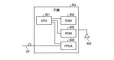
次に、図4を用いて、本実施形態にかかる光リピータシステムが有する子機RUのハードウェア構成の一例について説明する。図4は、本実施形態にかかる光リピータシステムが有する子機のハードウェア構成の一例を示すブロック図である。以下の説明では、親機MUと同様の構成については説明を省略する。 Next, an example of the hardware configuration of the slave unit RU included in the optical repeater system according to this embodiment will be described with reference to FIG. FIG. 4 is a block diagram showing an example of a hardware configuration of a child device included in the optical repeater system according to this embodiment. In the following description, description of the same configuration as that of the base unit MU will be omitted.
図4に示すように、本実施形態にかかる子機RUも、親機MUと同様に、CPU401、RAM402、ROM403、FPGA404、およびアンテナ405を有する。 As shown in FIG. 4, the slave unit RU according to this embodiment also has a CPU 401, a RAM 402, a
アンテナ405は、電波を発して、携帯端末との無線通信を可能にするアンテナである。
RAM402は、親機HU、中継機HU、または他の子機RUから受信する分割ファイル等の各種情報を一時的に記憶する一時記憶部の一例である。また、RAM402は、後述するCPU401がソフトウェアプログラムを実行する際の作業領域として機能する。 The RAM 402 is an example of a temporary storage unit that temporarily stores various information such as divided files received from the master unit HU, the relay unit HU, or another slave unit RU. Also, the RAM 402 functions as a work area when the CPU 401, which will be described later, executes a software program.
ROM403は、親機HU、中継機HU、または他の子機RUから受信する分割ファイルや後述するCPU401が実行するソフトウェアプログラム等の各種情報を記憶する不揮発性の記憶部(保存部)の一例である。 The
CPU401は、プロセッサの一例であり、RAM402を作業領域として用いて、ROM403に記憶されるソフトウェアプログラムを実行して子機RU全体を制御する。 The CPU 401 is an example of a processor, uses the RAM 402 as a work area, executes software programs stored in the
また、CPU401は、親機MUのCPU201と同様に、RAM402およびROM403への分割ファイルの格納、およびROM403からの分割ファイルの読み出し等の各種処理を実行する。 Further, CPU 401 executes various processes such as storing divided files in RAM 402 and
これにより、無線通信に用いる新たな周波数帯域への対応や無線通信に用いる周波数帯域の拡張によるFPGA404の大容量化に伴い、更新用ファイルのデータ量が多くなっても、当該更新用ファイル全体のデータ量に合わせて、RAM402を大容量化させる必要がなくなる。その結果、子機RUに実装する基板が占める面積の増加、および、子機RU内の回路設計の検討やソフトウェアプログラムのアップデートの長時間化を防止することができる。 As a result, even if the data amount of the update file increases due to the increase in capacity of the FPGA 404 due to support for new frequency bands used for wireless communication and expansion of the frequency band used for wireless communication, the entire update file can be stored. It becomes unnecessary to increase the capacity of the RAM 402 according to the amount of data. As a result, it is possible to prevent an increase in the area occupied by the board mounted on the slave unit RU and an increase in the time taken to examine the circuit design in the slave unit RU and update the software program.
ただし、中継機HUのCPU301は、親機MUと異なり、後述するFPGA404によって他の光伝送装置(通信経路において、子機RU自身よりも上位側(上流側)に接続される親機MUや、中継機HU、他の子機RU)から受信する分割ファイルを、RAM402およびROM403へ書き込むものとする。 However, unlike the parent device MU, the
FPGA404は、光ファイバOFを介して、無線基地局BSと、アンテナ405を用いて無線通信可能な範囲に位置する携帯端末と、の通信を中継する。また、FPGA404は、光ファイバOFを介して、親機MU、中継機HU、または他の子機RUから、分割ファイルを受信する。また、FPGA404は、CPU401によってROM403から読み出される分割ファイルを、光ファイバOFを介して他の光伝送装置(通信経路において、子機RU自身よりも下位側(下流側)に接続される子機RU)に送信する。 The FPGA 404 relays communication between the wireless base station BS and mobile terminals located within a wireless communication range using the
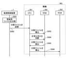
次に、図5を用いて、本実施形態にかかる光リピータシステムが有する親機MUによる更新用ファイルの送受信処理の流れの一例について説明する。図5は、本実施形態にかかる光リピータシステムが有する親機による更新用ファイルの送受信処理の流れの一例を示すシーケンス図である。 Next, an example of the flow of transmission/reception processing of an update file by the master unit MU of the optical repeater system according to the present embodiment will be described with reference to FIG. FIG. 5 is a sequence diagram showing an example of the flow of transmission/reception processing of an update file by the parent device of the optical repeater system according to this embodiment.
監視制御装置1は、更新用ファイルを生成すると、当該更新用ファイルをN個(ここで、Nは、2以上の整数である)の分割ファイルに分割する(ステップS501)。次いで、監視制御装置1は、更新用ファイルを、ネットワークNTを介して、分割ファイル毎に、親機MUに送信する(ステップS502)。監視制御装置1は、更新用ファイルを分割した分割ファイルの数(N個)の分、親機MUへの分割ファイルの送信を繰り返す。 After generating the update file, the
親機MUのCPU201は、監視制御装置1から、ネットワークNTを介して、分割ファイルを受信すると、当該分割ファイルを、RAM202に書き込む(ステップS503)。次いで、CPU201は、RAM202に書き込んだ分割ファイルが正常であるか否かを判断する(ステップS504)。 When
さらに、CPU201は、RAM202から、分割ファイルを読み出し(ステップS505)、当該読み出した分割ファイルをROM203に格納する(ステップS506)。ただし、ステップS504において分割ファイルが正常でないと判断した場合には、CPU201は、RAM202に記憶される分割ファイルをROM203に書き込まない。 Further, the
CPU201は、ステップS503~ステップS506に示す処理を、更新用ファイルを分割した分割ファイルの数(N個)の分、繰り返す。 The
ROM203に分割ファイルが書き込まれると、CPU201は、ROM203から、分割ファイルを読み出し、当該読み出した分割ファイルをFPGA204に転送する。FPGA204は、CPU201から入力される分割ファイルを、光ファイバOFを介して接続される中継機HUまたは子機RUに送信する。 When the split files are written in the
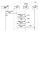
次に、図6を用いて、本実施形態にかかる光リピータシステムが有する中継機HUまたは子機RUによる更新用ファイルの送受信処理の流れの一例について説明する。図6は、本実施形態にかかる光リピータシステムが有する中継機または子機による更新用ファイルの送受信処理の流れの一例を示すシーケンス図である。以下の説明では、中継機HUにおける更新用ファイルの送受信処理について説明するが、子機RUにおいても同様にして、更新用ファイルの送受信処理が行われる。 Next, an example of the flow of transmission/reception processing of an update file by the repeater HU or slave unit RU of the optical repeater system according to the present embodiment will be described with reference to FIG. FIG. 6 is a sequence diagram showing an example of the flow of transmission/reception processing of an update file by a relay device or slave device of the optical repeater system according to this embodiment. In the following description, transmission/reception processing of the update file in the repeater HU will be described, but transmission/reception processing of the update file is similarly performed in the slave unit RU.
親機MUのFPGA204は、CPU201から入力される分割ファイルを、光ファイバOFを介して中継機HUに送信する(ステップS601)。FPGA204は、更新用ファイルを分割した分割ファイルの数(N個)の分、中継機HUへの分割ファイルの送信を繰り返す。
中継機HUのCPU301は、親機MUから、光ファイバOFを介して、分割ファイルを受信すると、受信した分割ファイルを、RAM302に書き込む(ステップS602)。次いで、CPU301は、RAM302に書き込んだ分割ファイルが正常であるか否かを判断する(ステップS603)。 When
さらに、CPU301は、RAM302から、分割ファイルを読み出し(ステップS604)、当該読み出した分割ファイルをROM303に書き込む(ステップS605)。ただし、ステップS603において分割ファイルが正常でないと判断した場合には、CPU301は、RAM302に記憶される分割ファイルをROM303に書き込まない。 Further, the
CPU301は、ステップS602~ステップS605に示す処理を、更新用ファイルを分割した分割ファイルの数(N個)の分、繰り返す。 The
ROM303に分割ファイルが書き込まれると、CPU301は、ROM303から、分割ファイルを読み出し、当該読み出した分割ファイルをFPGA304に転送する。FPGA304は、CPU301から入力される分割ファイルを、光ファイバOFを介して接続される中継機HUまたは子機RUに送信する。 When the split files are written to the
このように、本実施形態にかかる光リピータシステムによれば、無線通信に用いる新たな周波数帯域への対応や無線通信に用いる周波数帯域の拡張によるFPGA204,304,404の大容量化等に伴って、更新用ファイルのデータ量が多くなっても、当該更新用ファイル全体のデータ量に合わせて、RAM202,302,402を大容量化させる必要がなくなる。その結果、親機MUや、中継機HU、子機RUに実装する基板が占める面積の増加、および、親機MUや、中継機HU、子機RU内の回路設計の検討やソフトウェアプログラムのアップデートの長時間化を防止することができる。 As described above, according to the optical repeater system according to the present embodiment, as the capacity of the
本発明の実施形態を説明したが、この実施形態は、例として提示したものであり、発明の範囲を限定することは意図していない。この新規な実施形態は、その他の様々な形態で実施されることが可能であり、発明の要旨を逸脱しない範囲で、種々の省略、置き換え、変更を行うことができる。これら実施形態やその変形は、発明の範囲や要旨に含まれるとともに、特許請求の範囲に記載された発明とその均等の範囲に含まれる。 While embodiments of the invention have been described, the embodiments have been presented by way of example and are not intended to limit the scope of the invention. This novel embodiment can be embodied in various other forms, and various omissions, replacements, and modifications can be made without departing from the scope of the invention. These embodiments and their modifications are included in the scope and gist of the invention, and are included in the scope of the invention described in the claims and equivalents thereof.
1 監視制御装置
201,301,401 CPU
202,302,402 RAM
203,303,403 ROM
204,304,404 FPGA
405 アンテナ
BS 無線基地局
MU 親機
HU 中継機
RU 子機
NT ネットワーク
OF 光ファイバ1
202, 302, 402 RAM
203, 303, 403 ROMs
204, 304, 404 FPGAs
405 Antenna BS Radio Base Station MU Master HU Repeater RU Handset NT Network OF Optical fiber
Claims (7)
Translated fromJapaneseソフトウェアプログラムを記憶する記憶部と、
前記伝送システムの他の伝送装置から、前記ソフトウェアプログラムのアップデートに用いる更新用ファイルを分割した分割ファイルを受信するFPGAと、
前記分割ファイルを記憶する一時記憶部と、
前記FPGAにより受信する前記分割ファイルを前記一時記憶部に書き込み、前記一時記憶部に記憶される前記分割ファイルを前記記憶部に書き込むプロセッサと、を備え、
前記分割ファイルには、前記更新用ファイルのファイル識別子と、が付加され、
前記プロセッサは、前記記憶部に記憶される前記分割ファイルに付加される前記ファイル識別子に基づいて、前記分割ファイルが、前記伝送装置自身の前記ソフトウェアプログラムのアップデートに用いる前記分割ファイルか否かを判断し、前記分割ファイルが、前記伝送装置自身の前記ソフトウェアプログラムのアップデートに用いる前記分割ファイルではないと判断した場合、前記分割ファイルを他の前記伝送装置に送信後、前記分割ファイルを前記記憶部から削除する、伝送装置。A transmission device used in a transmission system that relays wireless communication between a wireless base station and a mobile terminal,
a storage unit that stores a software program;
an FPGA that receives split files obtained by splitting an update file used for updating the software program from another transmission device of the transmission system;
a temporary storage unit that stores the split files;
a processor that writes the split files received by the FPGA into the temporary storage unit and writes the split files stored in the temporary storage unit into the storage unit;
A file identifier of the update file is added to the split file,
The processor determines whether or not the split file is the split file used for updating the software program of the transmission device itself, based on the file identifier added to the split file stored in the storage unit. and if it is determined that the split file is not the split file used for updating the software program of the transmission device itself, the split file is transmitted from the storage unit after the split file is transmitted to the other transmission device. The transmission deviceto be deleted .
前記FPGAは、前記プロセッサにより読み出される前記分割ファイルを他の前記伝送装置に送信する請求項1に記載の伝送装置。The processor reads the split files from the storage unit,
2. The transmission device according to claim 1, wherein said FPGA transmits said split files read by said processor to other said transmission devices.
前記プロセッサは、前記待機系の記憶領域に記憶される前記ソフトウェアプログラムを、前記更新用ファイルを用いてアップデートし、アップデート後、前記待機系の記憶領域を前記稼働系の記憶領域に変更する請求項1から5のいずれか一に記載の伝送装置。The storage unit further has an active storage area for storing the software program to be executed in the transmission device and a standby storage area for storing the software program for update,
The processor updates the software program stored in the standby storage area using the update file, and after the update, changes the standby storage area to the active storage area. 6. The transmission device according to any one of 1 to 5.
前記プロセッサは、前記装置識別子が前記伝送装置自身を示しているにも関わらず、前記分割ファイルが、前記伝送装置自身の前記ソフトウェアプログラムのアップデートに用いる前記分割ファイルでないと判断されて、前記分割ファイルが前記記憶部から削除された場合、前記ソフトウェアプログラムがアップデートされなかったことを、外部の監視制御装置に通知する請求項1から6のいずれか一に記載の伝送装置。a device identifier of the transmission device that updates the software program with the split file is added to the split file;
The processor determines that the split file is not the split file used for updating the software program of the transmission device itself, even though the device identifier indicates the transmission device itself. 7. The transmission deviceaccording to any one of claims 1 to 6, wherein , when the software program has been deleted from the storage unit, an external supervisory control device is notified that the software program has not been updated.
Priority Applications (1)
| Application Number | Priority Date | Filing Date | Title |
|---|---|---|---|
| JP2019114749AJP7309471B2 (en) | 2019-06-20 | 2019-06-20 | transmission equipment |
Applications Claiming Priority (1)
| Application Number | Priority Date | Filing Date | Title |
|---|---|---|---|
| JP2019114749AJP7309471B2 (en) | 2019-06-20 | 2019-06-20 | transmission equipment |
Publications (2)
| Publication Number | Publication Date |
|---|---|
| JP2021002150A JP2021002150A (en) | 2021-01-07 |
| JP7309471B2true JP7309471B2 (en) | 2023-07-18 |
Family
ID=73995028
Family Applications (1)
| Application Number | Title | Priority Date | Filing Date |
|---|---|---|---|
| JP2019114749AActiveJP7309471B2 (en) | 2019-06-20 | 2019-06-20 | transmission equipment |
Country Status (1)
| Country | Link |
|---|---|
| JP (1) | JP7309471B2 (en) |
Citations (4)
| Publication number | Priority date | Publication date | Assignee | Title |
|---|---|---|---|---|
| JP2004234511A (en) | 2003-01-31 | 2004-08-19 | Nec Corp | Software updating system, portable terminal, software updating method, and program |
| JP2009188930A (en) | 2008-02-08 | 2009-08-20 | Kansai Electric Power Co Inc:The | COMMUNICATION SYSTEM, POWER SUPPLY MONITORING / CONTROL SYSTEM USING THE SAME, AND METHOD FOR UPDATING FIRMWARE IN COMMUNICATION SYSTEM |
| JP2011525725A (en) | 2008-05-19 | 2011-09-22 | エルジーシー ワイヤレス,インコーポレイティド | Method and system for performing on-site maintenance of a wireless communication system |
| WO2011121671A1 (en) | 2010-03-31 | 2011-10-06 | 富士通株式会社 | Firmware updating method, communication unit, and program |
- 2019
- 2019-06-20JPJP2019114749Apatent/JP7309471B2/enactiveActive
Patent Citations (4)
| Publication number | Priority date | Publication date | Assignee | Title |
|---|---|---|---|---|
| JP2004234511A (en) | 2003-01-31 | 2004-08-19 | Nec Corp | Software updating system, portable terminal, software updating method, and program |
| JP2009188930A (en) | 2008-02-08 | 2009-08-20 | Kansai Electric Power Co Inc:The | COMMUNICATION SYSTEM, POWER SUPPLY MONITORING / CONTROL SYSTEM USING THE SAME, AND METHOD FOR UPDATING FIRMWARE IN COMMUNICATION SYSTEM |
| JP2011525725A (en) | 2008-05-19 | 2011-09-22 | エルジーシー ワイヤレス,インコーポレイティド | Method and system for performing on-site maintenance of a wireless communication system |
| WO2011121671A1 (en) | 2010-03-31 | 2011-10-06 | 富士通株式会社 | Firmware updating method, communication unit, and program |
Also Published As
| Publication number | Publication date |
|---|---|
| JP2021002150A (en) | 2021-01-07 |
Similar Documents
| Publication | Publication Date | Title |
|---|---|---|
| KR101941618B1 (en) | Operating system hot-switching method and apparatus and mobile terminal | |
| CN110177028B (en) | Distributed health examination method and device | |
| CN108241500B (en) | Method, device and system for repairing hardware component and storage medium | |
| EP2660761A1 (en) | Timestamp management method for data synchronization and terminal therefor | |
| CN106445548B (en) | Test packet issuing method and device | |
| US11432175B2 (en) | Measurement reporting control method and related product | |
| US10462016B2 (en) | Communication control system, communication control method, and recording medium | |
| US20160173606A1 (en) | Information processing apparatus, communications apparatus, information processing method, and computer product | |
| US10862698B2 (en) | Method and device for searching for and controlling controllees in smart home system | |
| CN112738913B (en) | Ad hoc network system, communication method, communication device, computer equipment and storage medium | |
| CN111212439A (en) | Mobile terminal testing device, mobile terminal testing system and NSA testing method | |
| JP7309471B2 (en) | transmission equipment | |
| US11029944B2 (en) | Device and method of managing data of distributed antenna system | |
| CN107818027B (en) | Method and device for switching main name node and standby name node and distributed system | |
| US9166676B2 (en) | Telematics communication system and method | |
| CN102893583B (en) | Determine that the best be associated with recovery plan transmits condition in a communication network | |
| JP6232757B2 (en) | Message transfer system, communication terminal, management device, and message transfer method | |
| WO2024013812A1 (en) | Wireless communication system, terminal device, base station device, control device, and wireless communication scheme selection method | |
| CN116501529A (en) | Fault processing method and device, storage medium and electronic equipment | |
| US11432151B1 (en) | Wireless gateway with multiple processors managed by trusted processor | |
| US9408019B2 (en) | Accessing serial console port of a wireless access point | |
| US20160373464A1 (en) | Communication system, method and base station | |
| JP2023543079A (en) | Sounding reference signal arrangement method, network side equipment and readable storage medium | |
| JP4005044B2 (en) | Communication test equipment | |
| US20250251943A1 (en) | System and method for registering and relaying custom events and notices from node device to node device in peripheral device workspaces managed by a remote peripheral device cloud orchestrator server |
Legal Events
| Date | Code | Title | Description |
|---|---|---|---|
| A621 | Written request for application examination | Free format text:JAPANESE INTERMEDIATE CODE: A621 Effective date:20220217 | |
| A977 | Report on retrieval | Free format text:JAPANESE INTERMEDIATE CODE: A971007 Effective date:20221222 | |
| A131 | Notification of reasons for refusal | Free format text:JAPANESE INTERMEDIATE CODE: A131 Effective date:20230131 | |
| A521 | Request for written amendment filed | Free format text:JAPANESE INTERMEDIATE CODE: A523 Effective date:20230403 | |
| TRDD | Decision of grant or rejection written | ||
| A01 | Written decision to grant a patent or to grant a registration (utility model) | Free format text:JAPANESE INTERMEDIATE CODE: A01 Effective date:20230606 | |
| A61 | First payment of annual fees (during grant procedure) | Free format text:JAPANESE INTERMEDIATE CODE: A61 Effective date:20230705 | |
| R150 | Certificate of patent or registration of utility model | Ref document number:7309471 Country of ref document:JP Free format text:JAPANESE INTERMEDIATE CODE: R150 | |
| S111 | Request for change of ownership or part of ownership | Free format text:JAPANESE INTERMEDIATE CODE: R313115 | |
| R350 | Written notification of registration of transfer | Free format text:JAPANESE INTERMEDIATE CODE: R350 |