JP7306197B2 - Printer and cassette for printing - Google Patents
Printer and cassette for printingDownload PDFInfo
- Publication number
- JP7306197B2 JP7306197B2JP2019178159AJP2019178159AJP7306197B2JP 7306197 B2JP7306197 B2JP 7306197B2JP 2019178159 AJP2019178159 AJP 2019178159AJP 2019178159 AJP2019178159 AJP 2019178159AJP 7306197 B2JP7306197 B2JP 7306197B2
- Authority
- JP
- Japan
- Prior art keywords
- input
- case
- output
- section
- Prior art date
- Legal status (The legal status is an assumption and is not a legal conclusion. Google has not performed a legal analysis and makes no representation as to the accuracy of the status listed.)
- Active
Links
Images


Classifications
- B—PERFORMING OPERATIONS; TRANSPORTING
- B41—PRINTING; LINING MACHINES; TYPEWRITERS; STAMPS
- B41J—TYPEWRITERS; SELECTIVE PRINTING MECHANISMS, i.e. MECHANISMS PRINTING OTHERWISE THAN FROM A FORME; CORRECTION OF TYPOGRAPHICAL ERRORS
- B41J17/00—Mechanisms for manipulating page-width impression-transfer material, e.g. carbon paper
- B41J17/32—Detachable carriers or holders for impression-transfer material mechanism
- B—PERFORMING OPERATIONS; TRANSPORTING
- B41—PRINTING; LINING MACHINES; TYPEWRITERS; STAMPS
- B41J—TYPEWRITERS; SELECTIVE PRINTING MECHANISMS, i.e. MECHANISMS PRINTING OTHERWISE THAN FROM A FORME; CORRECTION OF TYPOGRAPHICAL ERRORS
- B41J15/00—Devices or arrangements of selective printing mechanisms, e.g. ink-jet printers or thermal printers, specially adapted for supporting or handling copy material in continuous form, e.g. webs
- B41J15/04—Supporting, feeding, or guiding devices; Mountings for web rolls or spindles
- B41J15/044—Cassettes or cartridges containing continuous copy material, tape, for setting into printing devices
- B—PERFORMING OPERATIONS; TRANSPORTING
- B41—PRINTING; LINING MACHINES; TYPEWRITERS; STAMPS
- B41J—TYPEWRITERS; SELECTIVE PRINTING MECHANISMS, i.e. MECHANISMS PRINTING OTHERWISE THAN FROM A FORME; CORRECTION OF TYPOGRAPHICAL ERRORS
- B41J15/00—Devices or arrangements of selective printing mechanisms, e.g. ink-jet printers or thermal printers, specially adapted for supporting or handling copy material in continuous form, e.g. webs
- B41J15/04—Supporting, feeding, or guiding devices; Mountings for web rolls or spindles
- B—PERFORMING OPERATIONS; TRANSPORTING
- B41—PRINTING; LINING MACHINES; TYPEWRITERS; STAMPS
- B41J—TYPEWRITERS; SELECTIVE PRINTING MECHANISMS, i.e. MECHANISMS PRINTING OTHERWISE THAN FROM A FORME; CORRECTION OF TYPOGRAPHICAL ERRORS
- B41J2/00—Typewriters or selective printing mechanisms characterised by the printing or marking process for which they are designed
- B41J2/315—Typewriters or selective printing mechanisms characterised by the printing or marking process for which they are designed characterised by selective application of heat to a heat sensitive printing or impression-transfer material
- B—PERFORMING OPERATIONS; TRANSPORTING
- B41—PRINTING; LINING MACHINES; TYPEWRITERS; STAMPS
- B41J—TYPEWRITERS; SELECTIVE PRINTING MECHANISMS, i.e. MECHANISMS PRINTING OTHERWISE THAN FROM A FORME; CORRECTION OF TYPOGRAPHICAL ERRORS
- B41J3/00—Typewriters or selective printing or marking mechanisms characterised by the purpose for which they are constructed
- B41J3/36—Typewriters or selective printing or marking mechanisms characterised by the purpose for which they are constructed for portability, i.e. hand-held printers or laptop printers
- B—PERFORMING OPERATIONS; TRANSPORTING
- B41—PRINTING; LINING MACHINES; TYPEWRITERS; STAMPS
- B41J—TYPEWRITERS; SELECTIVE PRINTING MECHANISMS, i.e. MECHANISMS PRINTING OTHERWISE THAN FROM A FORME; CORRECTION OF TYPOGRAPHICAL ERRORS
- B41J32/00—Ink-ribbon cartridges
- B—PERFORMING OPERATIONS; TRANSPORTING
- B41—PRINTING; LINING MACHINES; TYPEWRITERS; STAMPS
- B41J—TYPEWRITERS; SELECTIVE PRINTING MECHANISMS, i.e. MECHANISMS PRINTING OTHERWISE THAN FROM A FORME; CORRECTION OF TYPOGRAPHICAL ERRORS
- B41J33/00—Apparatus or arrangements for feeding ink ribbons or like character-size impression-transfer material
- B41J33/14—Ribbon-feed devices or mechanisms
- B41J33/24—Ribbon-feed devices or mechanisms with drive applied directly to ribbon
- B41J33/26—Ribbon-feed devices or mechanisms with drive applied directly to ribbon by rollers engaging the ribbon
Landscapes
- Impression-Transfer Materials And Handling Thereof (AREA)
- Printers Characterized By Their Purpose (AREA)
- Handling Of Continuous Sheets Of Paper (AREA)
- Electronic Switches (AREA)
- Handling Of Sheets (AREA)
Description
Translated fromJapanese本開示は、印刷装置及び印刷用カセットに関する。 The present disclosure relates to printing devices and printing cassettes.
テープに印刷等の処理を行う装置では、テープを収納したカセットを本体に着脱することで、テープの交換及び供給が行われる。このような装置に用いられるカセットとして、テープが巻回されたリールにギアを設けたものが知られている(特許文献1参照)。 2. Description of the Related Art In a device that performs processing such as printing on a tape, the tape is exchanged and supplied by attaching and detaching a cassette containing the tape to and from the main body. As a cassette used in such a device, there is known a cassette in which a reel on which a tape is wound is provided with a gear (see Patent Document 1).
上述のカセットで、上記ギアを用いてカセットから駆動力を出力する場合、出力部(つまりギア)と入力部(つまりリールの穴)とが共にリールに形成されているため、カセットへの入力位置とカセット外部への出力位置との配置に制限が生じる。 In the cassette described above, when the driving force is output from the cassette using the gear, both the output portion (that is, the gear) and the input portion (that is, the hole in the reel) are formed on the reel, so the input position to the cassette and the output position to the outside of the cassette is restricted.
本開示の一局面は、カセットへの駆動力入力位置とカセット外部への駆動力出力位置との配置の自由度を高められる印刷装置及び印刷用カセットを提供することを目的とする。 An object of one aspect of the present disclosure is to provide a printing apparatus and a printing cassette that can increase the degree of freedom in arranging a driving force input position to the cassette and a driving force output position to the outside of the cassette.
本開示の一態様は、被印刷テープを有する印刷用カセットと、被印刷テープを搬送するプラテンローラと、駆動源と、を備える印刷装置である。 One aspect of the present disclosure is a printing apparatus that includes a printing cassette having a print-receiving tape, a platen roller that conveys the print-receiving tape, and a drive source.
印刷用カセットは、駆動源からの駆動力が入力される入力部と、第1方向と平行な回転軸心周りに回転すると共に、プラテンローラに駆動力を伝達する出力部と、入力部と出力部とに駆動連結され、入力部に入力された駆動力を出力部に伝達する伝達機構と、被印刷テープの少なくとも一部、入力部の少なくとも一部、出力部の少なくとも一部、及び伝達機構の少なくとも一部が内部に配置されたケースと、を有する。 The printing cassette has an input section to which the driving force from the driving source is input, an output section that rotates around a rotation axis parallel to the first direction and transmits the driving force to the platen roller, an input section and an output. and a transmission mechanism for transmitting the driving force input to the input section to the output section; at least a portion of the tape to be printed; at least a portion of the input section; at least a portion of the output section; and a case in which at least a portion of the
出力部の一部は、ケースの外に位置する。出力部及びケースを第1方向と垂直な仮想面に投影した投影図において、出力部は、ケースの外縁よりも内側に位置する。 A portion of the output is located outside the case. In a projection view in which the output section and the case are projected onto a virtual plane perpendicular to the first direction, the output section is located inside the outer edge of the case.
本開示の別の態様は、被印刷テープと、駆動力が入力される入力部と、第1方向と平行な回転軸心周りに回転すると共に、被印刷テープを搬送するための駆動力を外部に出力するための出力部と、入力部と出力部とに駆動連結され、入力部に入力された駆動力を出力部に伝達する伝達機構と、被印刷テープの少なくとも一部、入力部の少なくとも一部、出力部の少なくとも一部、及び伝達機構の少なくとも一部が内部に配置されたケースと、を備える印刷用カセットである。 Another aspect of the present disclosure is a tape to be printed, an input unit to which a driving force is input, and a driving force for feeding the tape to be printed while rotating around a rotation axis parallel to the first direction. a transmission mechanism that is drivingly connected to the input section and the output section and transmits the driving force input to the input section to the output section; at least a portion of the tape to be printed; A printing cassette comprising a case in which a portion, at least a portion of an output section, and at least a portion of a transmission mechanism are arranged.
出力部の一部は、ケースの外に位置する。出力部及びケースを第1方向と垂直な仮想面に投影した投影図において、出力部は、ケースの外縁よりも内側に位置する。 A portion of the output is located outside the case. In a projection view in which the output section and the case are projected onto a virtual plane perpendicular to the first direction, the output section is located inside the outer edge of the case.
これらのような構成によれば、伝達機構によって入力部から出力部へと駆動力が伝達できるため、入力部と出力部とを任意の位置に配置することができる。その結果、印刷用カセットへの駆動力の入力位置と印刷用カセット外部への駆動力の出力位置との配置の自由
度を高められる。また、上記投影図において出力部がケースの外縁よりも内側に位置するので、出力部の保護も図られる。According to such a configuration, since the driving force can be transmitted from the input section to the output section by the transmission mechanism, the input section and the output section can be arranged at arbitrary positions. As a result, it is possible to increase the degree of freedom in arranging the input position of the driving force to the printing cassette and the output position of the driving force to the outside of the printing cassette. In addition, since the output section is positioned inside the outer edge of the case in the projection view, the output section is also protected.
本開示のさらに別の態様は、被印刷テープと、駆動力が入力される入力部と、第1方向と平行な回転軸心周りに回転すると共に、被印刷テープを搬送するための駆動力を外部に出力するための出力部と、入力部と出力部とに駆動連結され、入力部に入力された駆動力を出力部に伝達する伝達機構と、被印刷テープの少なくとも一部、入力部の少なくとも一部、出力部の少なくとも一部、及び伝達機構の少なくとも一部が内部に配置されたケースと、を備える印刷用カセットである。 According to still another aspect of the present disclosure, a print-receiving tape, an input unit to which a driving force is input, and a driving force for rotating around a rotation axis parallel to the first direction and conveying the print-receiving tape are provided. an output unit for outputting to the outside; a transmission mechanism drivingly connected to the input unit and the output unit and transmitting the driving force input to the input unit to the output unit; A printing cassette comprising a case in which at least a portion, at least a portion of an output section, and at least a portion of a transmission mechanism are arranged.
出力部の一部は、ケースの外に位置する。出力部の全体は、第1方向において、ケースと重なる。 A portion of the output is located outside the case. The entire output portion overlaps the case in the first direction.
このような構成によれば、伝達機構によって入力部から出力部へと駆動力が伝達できるため、入力部と出力部とを任意の位置に配置することができる。また、出力部の全体が第1方向においてケースと重なるので、出力部の保護も図られる。 According to such a configuration, since the driving force can be transmitted from the input section to the output section by the transmission mechanism, the input section and the output section can be arranged at arbitrary positions. Moreover, since the entirety of the output section overlaps the case in the first direction, the output section is also protected.
本開示のさらに別の態様は、被印刷テープと、駆動力が入力される入力部と、第1方向と平行な回転軸心周りに回転すると共に、被印刷テープを搬送するための駆動力を外部に出力するための出力部と、入力部と出力部とに駆動連結され、入力部に入力された駆動力を出力部に伝達する伝達機構と、被印刷テープの少なくとも一部、入力部の少なくとも一部、出力部の少なくとも一部、及び伝達機構の少なくとも一部が内部に配置されたケースと、を備える印刷用カセットである。 According to still another aspect of the present disclosure, a print-receiving tape, an input unit to which a driving force is input, and a driving force for rotating around a rotation axis parallel to the first direction and conveying the print-receiving tape are provided. an output unit for outputting to the outside; a transmission mechanism drivingly connected to the input unit and the output unit and transmitting the driving force input to the input unit to the output unit; A printing cassette comprising a case in which at least a portion, at least a portion of an output section, and at least a portion of a transmission mechanism are arranged.
ケースは、ケースの第1方向と直交する第2方向における端面をそれぞれ構成する第1面と及び第2面と、ケースの第1方向及び第2方向の双方と直交する第3方向における端面をそれぞれ構成する第3面と及び第4面と、を有する。出力部は、第1面と第2面との間、かつ、第3面と第4面との間に位置する。 The case has a first surface and a second surface respectively forming end surfaces in a second direction orthogonal to the first direction of the case, and an end surface in a third direction orthogonal to both the first direction and the second direction of the case. It has a third surface and a fourth surface that constitute respectively. The output portion is located between the first and second surfaces and between the third and fourth surfaces.
このような構成によれば、伝達機構によって入力部から出力部へと駆動力が伝達できるため、入力部と出力部とを任意の位置に配置することができる。また、出力部が第1面と第2面との間、かつ、第3面と第4面との間に位置するので、出力部の保護も図られる。 According to such a configuration, since the driving force can be transmitted from the input section to the output section by the transmission mechanism, the input section and the output section can be arranged at arbitrary positions. In addition, since the output section is positioned between the first and second surfaces and between the third and fourth surfaces, the output section is also protected.
[1.第1実施形態]
[1-1.構成]
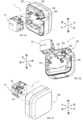
図1A,1B,1Cに示す印刷装置1は、印刷用カセット10と、印刷装置本体100とを備える。印刷装置1は、テープ状の印刷媒体に印刷を行う装置である。[1. First Embodiment]
[1-1. composition]
A
本実施形態では、出力ギア18の軸方向を上下方向とし、上下方向と垂直な方向のうち出力ギア18と入力スプール16とが並ぶ方向を前後方向とし、上下方向と前後方向との双方に垂直な方向を左右方向とする。 In this embodiment, the axial direction of the
<印刷用カセット>
印刷用カセット10は、印刷媒体を格納している。印刷用カセット10は、印刷装置本体100に着脱可能である。印刷用カセット10の交換により、印刷媒体の補給、及び印刷媒体の種類(例えば、色、材質等)の変更ができる。<Cassette for printing>
The
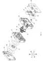
印刷用カセット10は、図2A,2B,2Cに示すように、後述する被印刷テープ、インクリボン等を格納するケース35を備える。印刷用カセット10の外形(つまり、ケース35の形状)は、上下方向に平行な辺と、前後方向に平行な辺と、左右方向に平行な辺とを有する直方体状である。ケース35は、第1蓋部31と、第1枠部32と、第2枠部33と、第2蓋部34とを有する。 As shown in FIGS. 2A, 2B, and 2C, the
印刷用カセット10は、図3に示すように、第1ロール11と、第1供給スプール12と、スペーサフィルム13A,13Bと、第2ロール14と、第2供給スプール15と、入力スプール16と、クラッチバネホルダ17と、出力ギア18と、入力ギア19と、アイドルギア20とを備える。 The
(第1ロール)
第1ロール11は、印刷が行われる被印刷テープを第1供給スプール12に巻回したものである。被印刷テープの表面には、後述する印刷装置本体100の印刷ヘッド102及びインクリボンによって印刷が行われる。(first roll)
The
第1ロール11の上下方向の外側には、第1ロール11を挟むように2つのスペーサフ
ィルム13A,13Bが配置されている。スペーサフィルム13A,13Bは、第1ロール11と第1蓋部31との間と、第1ロール11と第1枠部32との間とに配置されている。Two
(第1供給スプール)
第1供給スプール12は、回転軸心周りに回転可能である。第1供給スプール12は、後述する印刷装置本体100のプラテンローラ103による被印刷テープの搬送に伴って回転することで、被印刷テープを印刷ヘッド102に供給する。(First supply spool)
The
(第2ロール)
第2ロール14は、被印刷テープの印刷に用いられるインクリボンを第2供給スプール15に巻回したものである。(second roll)
The
インクリボンは、後述するヘッド開口33Bにおいて、被印刷テープと重ね合わされ、印刷ヘッド102による印刷に供される。印刷に使用されたインクリボンは、後述する入力スプール16に巻き取られる。また、第2ロール14には、クラッチバネホルダ17に保持されたクラッチバネによって回転抵抗が付される。 The ink ribbon is superimposed on the print tape at a
(第2供給スプール)
第2供給スプール15は、回転軸心周りに回転可能である。第2供給スプール15の回転軸心は、第1供給スプール12の回転軸心、つまり上下方向と平行である。(Second supply spool)
The
第2供給スプール15は、インクリボンの入力スプール16による巻き取りに伴って回転することで、インクリボンを印刷ヘッド102に供給する。また、第2供給スプール15の少なくとも一部は、上下方向において、第1ロール11と重なる位置に配置されている。 The
(入力スプール)
入力スプール16は、回転軸心周りに回転可能である。入力スプール16の回転軸心は、第2供給スプール15の回転軸心と平行である。(input spool)
The
入力スプール16は、円筒状であり、内周面16Aで規定される中空部を有する。入力スプール16の内周面16Aにはスプライン歯16Bが設けられている。スプライン歯16Bには、後述する印刷装置本体100の駆動シャフト105が連結される。入力スプール16は、駆動シャフト105によって回転され、インクリボンを巻き取る。 The
(出力ギア)
出力ギア18は、被印刷テープを搬送するための駆動力を外部に出力するためのギアである。出力ギア18は、後述する印刷装置本体100のプラテンギア104を介してプラテンローラ103に駆動力を伝達する出力部である。(output gear)
The
出力ギア18は、回転軸心周りに回転する円盤と、円盤の上下方向と平行な面に設けられた歯とを有する。円盤の上下方向と垂直な一方の面(つまり上面)は、上下方向においてケース35の後述するカバー部32Bと対向している。円盤の上下方向と垂直な他方の面(つまり下面)の一部は、上下方向においてケース35と対向していない。 The
出力ギア18は、ヘッド開口33Bに一部が露出しており、一部がケース35の外に位置している。出力ギア18は、印刷用カセット10が印刷装置本体100に装着された状態で、ヘッド開口33Bにおいてプラテンギア104に係合する。 The
図4に示すように、第1ロール11、出力ギア18、及び第2ロール14(つまり第2供給スプール15)は、上下方向において、第1ロール11、出力ギア18、及び第2ロール14の順に並んで配置されている。つまり、出力ギア18は、上下方向において、第1ロール11と第2ロール14との間に位置する。 As shown in FIG. 4 , the
(入力ギア)
図3に示すように、入力ギア19は、後述するアイドルギア20を介して出力ギア18と間接的に係合し、駆動力を出力ギア18に伝達するためのギアである。入力ギア19には、印刷装置本体100の駆動源からの駆動力が入力される。(input gear)
As shown in FIG. 3 , the
入力ギア19は、ギア19Aと、ギア19Aの下面に固定されると共に、内周面にスプライン歯を有する円筒状のスプール19Bとを有する。ギア19Aは、スプール19Bに入力された駆動力によってスプール19Bと一体回転する。 The
入力ギア19の回転軸心(つまり、ギア19Aの回転軸心及びスプール19Bの回転軸心)は、入力スプール16の回転軸心と同一線上に配置されている。図4に示すように、入力スプール16、入力ギア19、及び第1ロール11は、上下方向において、入力スプール16、入力ギア19、及び第1ロール11の順に並んで配置されている。 The rotation axis of the input gear 19 (that is, the rotation axis of the
つまり、入力ギア19は、上下方向において、入力スプール16と第1ロール11との間に位置する。また、入力ギア19の少なくとも一部は、上下方向において、第1ロール11と重なる位置に配置されている。 That is, the
入力ギア19の回転軸心は、入力スプール16の中空部を通る。つまり、駆動シャフト105が入力スプール16と入力ギア19とに同時に挿通される。その結果、入力ギア19は、入力スプール16と直接連結はされていないが、入力スプール16と共通の駆動源(つまり駆動シャフト105)によって回転される。 The rotation axis of the
(アイドルギア)
アイドルギア20は、入力ギア19と出力ギア18とに駆動連結され(つまり係合し)、入力ギア19に入力された駆動力を出力ギア18に伝達するための伝達機構を構成している。(idle gear)
The
アイドルギア20は、入力ギア19に係合した第1ギア20Aと、出力ギア18に係合した第2ギア20Bとが同軸上に並んで配置された段ギアである。第2ギア20Bは、第1ギア20Aよりも径が小さい。また、第2ギア20Bは、上下方向において、第1ギア20Aよりも第1ロール11に近い位置(つまり上方)に配置されている。アイドルギア20は、入力ギア19に入力された駆動力を減速させる減速機構を構成している。 The
(ケース)
図3に示すように、第1蓋部31は、印刷用カセット10の上端部を構成している。第1枠部32は、第1蓋部31の下側に配置され、第1蓋部31と上下方向に連結されている。第2枠部33は、第1枠部32の下側に配置され、第1枠部32と上下方向に連結されている。第2蓋部34は、印刷用カセット10の下端部を構成している。第2蓋部34は、第2枠部33と上下方向に連結されている。(Case)
As shown in FIG. 3 , the
第1蓋部31と第1枠部32とは、第1ロール11を収納する第1ケース部41(図4参照)を構成している。つまり、第1ロール11は、第1蓋部31と第1枠部32とで囲まれた空間に配置されている。 The
第2蓋部34と第2枠部33とは、第2ロール14、第2供給スプール15、及び入力スプール16を収納する第2ケース部42(図4参照)を構成している。つまり、第2ロール14、第2供給スプール15、及び入力スプール16は、第2蓋部34と第2枠部33とで囲まれた空間に配置されている。 The
第1枠部32と第2枠部33とは、出力ギア18の一部、入力ギア19、及びアイドルギア20が内部に配置された第3ケース部43(図4参照)を構成している。つまり、出力ギア18の一部、入力ギア19、及びアイドルギア20は、第1枠部32と第2枠部33とで囲まれた空間に配置されている。第3ケース部43は、上下方向において、第1ケース部41と第2ケース部42との間に配置されている。 The
第1枠部32は、第1側壁32Aと、カバー部32Bと、第1ガイド32Cと、第1ギア支持部32Dと、第2ギア支持部32Eと、第3ギア支持部32Fとを有する。第1側壁32Aは、印刷用カセット10の上下方向と平行な側面を構成する。カバー部32Bは、上下方向と垂直な表面を有する部位である。 The
カバー部32Bは、上下方向において出力ギア18と重なる位置に配置されている。本実施形態では、カバー部32Bは、第1側壁32Aの下端部と連続して設けられ、第1枠部32の右前方の角部に配置されている。 The
出力ギア18、カバー部32B、及び第1ロール11は、上下方向において、出力ギア18、カバー部32B、及び第1ロール11の順に並んで配置されている。また、上述のように、出力ギア18の上面の全領域は、カバー部32Bによって覆われている。 The
第1ガイド32Cは、図5に示すように、第1ロール11から引き出された被印刷テープ11Aが巻き掛けられる部位である。第1ガイド32Cは、第1ロール11の周方向に沿って離間して配置された複数の板状のリブを有する。複数のリブは、第1ロール11の径方向に突出しており、下方に向かうほど突出量(つまり板幅)が大きくなっている。 The
図3に示される第1ギア支持部32Dは、出力ギア18を回転可能に支持する。第2ギア支持部32Eは、入力ギア19を回転可能に支持する。第3ギア支持部32Fは、アイドルギア20を回転可能に支持する。 The first
第2枠部33は、第2側壁33Aと、ヘッド開口33Bと、排出口33Cと、第2ガイド33Dと、突出部33Eと、搬送路33Gとを有する。第2側壁33Aは、印刷用カセット10の上下方向と平行な側面を構成する。 The
ヘッド開口33Bは、第2側壁33Aの一部を切り欠いた部位である。ヘッド開口33Bは、印刷用カセット10が印刷装置本体100に装着された状態で、印刷ヘッド102が下方から挿入されることで、内部に印刷ヘッド102が配置される空間である。ヘッド開口33Bは、印刷用カセット10の下方に開口している。 The
第2ガイド33Dは、第1ガイド32Cを通過した被印刷テープ11Aが巻き掛けられる部位である。第2ガイド33Dは、第1ガイド32Cと同様に、第2ロール14の周方向に沿って離間して配置された複数の板状のリブを有する。複数のリブは、第2ロール14の径方向に突出しており、下方に向かうほど突出量(つまり板幅)が小さくなる。 The
突出部33Eは、上下方向において出力ギア18と重なる位置に配置されると共に、上下方向と平行な端面33Fを有する。突出部33Eは、出力ギア18の下側(つまり、出力ギア18を挟んでカバー部32Bとは反対側)に配置されている。 The projecting
搬送路33Gは、ヘッド開口33Bよりも被印刷テープの搬送方向の上流において被印刷テープとインクリボンとが平行に搬送される部位である。本実施形態では、搬送路33Gにおける被印刷テープの搬送方向は、左から右に向かう方向であり、搬送路33G内において、被印刷テープの被印刷面とは逆の面が当接する複数の支持点を結んだ直線と平行である。 The
入力ギア19の一部は、搬送路33Gにおける被印刷テープ11Aの搬送方向(つまり左右方向)と上下方向との双方とに垂直な方向(つまり前後方向)において、出力ギア18と重なっている。 A portion of the
図6に示すように、ヘッド開口33Bにおいて、被印刷テープ11A及びインクリボン14Aが左右方向に架け渡される。印刷後の被印刷テープ11Aは、排出口33Cから印刷装置1の外部に排出される。 As shown in FIG. 6, the
出力ギア18及びケース35を上下方向と垂直な仮想面に投影した投影図において、出力ギア18は、ケース35の外縁よりも内側に位置している。また、出力ギア18の全体は、上下方向において、ケース35と重なっている。 In a projection view in which the
出力ギア18の一部は、上下方向においてヘッド開口33Bと重なっている。特に、出力ギア18の回転軸心O1は、ヘッド開口33Bを通っている。また、突出部33Eの端面33Fは、出力ギア18の歯底円と、出力ギア18の回転軸心O1との間に位置している。 A portion of the
出力ギア18のうち、ケース35の外に位置している部分(つまり、突出部33Eと上下方向に重なっていない部分)の歯底円の周長Lは、出力ギア18の歯底円の周長の1/8以上1/3以下である。 The peripheral length L of the root circle of the portion of the
ケース35は、被印刷テープ11Aを支持する第1上流支持部331及び第1下流支持部332と、インクリボン14Aを支持する第2上流支持部333及び第2下流支持部334とをさらに有する。 The
第1上流支持部331は、ヘッド開口33Bよりも被印刷テープ11Aの搬送方向の上流においてヘッド開口33Bに隣接して設けられている。第1下流支持部332は、ヘッド開口33Bよりも被印刷テープ11Aの搬送方向の下流においてヘッド開口33Bに隣接して設けられている。第1下流支持部332は、第1上流支持部331よりも右後方に位置する。 The first
第2上流支持部333は、ヘッド開口33Bよりもインクリボン14Aの搬送方向の上流においてヘッド開口33Bに隣接して設けられている。第2下流支持部334は、ヘッド開口33Bよりもインクリボン14Aの搬送方向の下流においてヘッド開口33Bに隣接して設けられている。第2下流支持部334は、第2上流支持部333よりも右後方に位置する。 The second
第2上流支持部333と第2下流支持部334とを結ぶ仮想直線S2は、上下方向において、出力ギア18と重なっている。一方、第1上流支持部331と第1下流支持部332とを結ぶ仮想直線S1は、上下方向において、出力ギア18と重なっていない。そのため、ヘッド開口33Bにおいて被印刷テープ11Aとインクリボン14Aとは前後方向に離間して搬送される。また、出力ギア18は、上下方向において、第2上流支持部333と重なっている。 An imaginary straight line S2 connecting the second
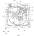
図7に示すように、出力ギア18の一部は、上下方向において、第1上流支持部331と第1下流支持部332と入力ギア19の回転軸心O2とを結ぶ仮想三角形S3と重なっている。特に、本実施形態では、出力ギア18の回転軸心O1が仮想三角形S3を通っている。 As shown in FIG. 7, a portion of the
図8A,8B,8C,8Dに示すように、第1ガイド32C及び第2ガイド33Dは、第1ロール11を構成する被印刷テープ11Aを第1ケース部41から第2ケース部42に送る通路を構成している。 As shown in FIGS. 8A, 8B, 8C, and 8D, the
具体的には、図8Aに示すように、第1ロール11から引き出された被印刷テープ11Aは、螺旋を描くように第1ガイド32Cに第1ロール11の径方向外側から当接しながら第1ケース部41内で下後方に向かって搬送される。被印刷テープ11Aは、さらに図8Bに示すように、第3ケース部43を上下方向に跨ぎつつ、左下方に向かって搬送される。 More specifically, as shown in FIG. 8A, the print-receiving
第2ケース部42に到達した被印刷テープ11Aは、図8Cに示すように、第2ガイド33Dに径方向外側から当接しながら下前方に向かって搬送される。印刷用カセット10の下端部に到達した被印刷テープ11Aは、図8Dに示すように、ヘッド開口33Bを通過して排出口33Cから排出される。 As shown in FIG. 8C, the print-receiving
また、出力ギア18は、図8Aに示すように、ケース35の第1面35Aと第2面35Bとの間に位置している。さらに、出力ギア18は、図8Dに示すように、ケース35の第3面35Cと第4面35Dとの間に位置している。 The
第1面35A及び第2面35Bは、ケース35の前後方向における端面をそれぞれ構成している。具体的には、第1面35Aは、最前面であり、第2面35Bは、最後面である。また、第3面35C及び第4面35Dは、ケース35の左右方向における端面をそれぞれ構成している。具体的には、第3面35Cは、最左面であり、第4面35Dは、最右面である。 The
<印刷装置本体>
印刷装置本体100は、図1Bに示すように、カセット挿入部101と、印刷ヘッド102と、プラテンローラ103と、プラテンギア104と、駆動シャフト105とを備える。<Printer body>
The printer
(カセット挿入部)
カセット挿入部101は、印刷用カセット10が装着される凹部である。カセット挿入部101は、印刷用カセット10の位置決め機能を有する。(cassette insertion part)
The
(印刷ヘッド)
印刷ヘッド102は、印刷用カセット10が保持する被印刷テープに印刷するための装置である。(print head)
The
印刷ヘッド102は、カセット挿入部101の内部に配置されている。印刷ヘッド102は、印刷用カセット10が印刷装置本体100に装着された状態で、ヘッド開口33Bにおいて、被印刷テープ及びインクリボンと前後方向に重なる位置に配置される。 The
印刷ヘッド102は、個別に発熱が制御される複数の発熱素子を有する。後述するプラテンローラ103によってヘッド開口33Bに搬送された被印刷テープは、インクリボン
を介して発熱素子が発熱した印刷ヘッド102に押し付けられる。これにより、インクリボンの表面に配置されたインクの一部が被印刷テープに転写され、被印刷テープに文字、記号等が印刷される。The
(プラテンローラ)
プラテンローラ103は、被印刷テープを印刷用カセット10内から外部に向けて搬送するためのローラである。プラテンローラ103の回転軸心は、上下方向と平行である。(platen roller)
The
プラテンローラ103は、カセット挿入部101の内部において、印刷ヘッド102の近傍に配置されている。プラテンローラ103は、ヘッド開口33Bにおいて被印刷テープに当接し、被印刷テープを印刷ヘッド102に押し当てる。 The
(プラテンギア)
プラテンギア104は、プラテンローラ103に連結され、出力ギア18と係合するギアである。本実施形態では、プラテンギア104の回転軸心は、プラテンローラ103の回転軸心と同一線上に配置されている。(Platen gear)
The
プラテンローラ103及びプラテンギア104は、図9に示す印刷用カセット10と離間した位置と、図7に示すプラテンギア104が出力ギア18に係合した位置との間で揺動可能である。 The
(駆動シャフト)
駆動シャフト105は、入力スプール16に挿入されると共に入力ギア19に係合し、入力スプール16と入力ギア19とを回転させるためのシャフトである。(drive shaft)
The
駆動シャフト105は、カセット挿入部101の内部に配置されている。駆動シャフト105の回転軸心は、上下方向と平行である。駆動シャフト105は、図示しない駆動源(例えばモータ)によって回転軸心を中心に回転する。 The
図7に示すように、印刷用カセット10が印刷装置本体100に装着された状態で、駆動シャフト105が入力ギア19に係合すると共にプラテンギア104が出力ギア18に係合する。具体的には、駆動シャフト105を印刷用カセット10の入力スプール16及び入力ギア19に挿入し、プラテンローラ103及びプラテンギア104を印刷用カセット10のヘッド開口33Bに向けて揺動させることで、印刷用カセット10が印刷装置本体100に装着される。 As shown in FIG. 7, when the
印刷用カセット10が装着された状態で駆動シャフト105により入力ギア19が回転されることで出力ギア18が回転され、出力ギア18の回転によりプラテンギア104が回転し、プラテンギア104の回転によりプラテンローラ103が回転する。 When the
[1-2.効果]
以上詳述した実施形態によれば、以下の効果が得られる。
(1a)アイドルギア20によって入力ギア19から出力ギア18へと駆動力が伝達できるため、入力ギア19と出力ギア18とを任意の位置に配置することができる。その結果、印刷用カセット10への駆動力の入力位置と印刷用カセット10外部への駆動力の出力位置との配置の自由度を高められる。また、上下方向の投影図において出力ギア18がケース35の外縁よりも内側に位置するので、出力ギア18の保護も図られる。[1-2. effect]
According to the embodiment detailed above, the following effects are obtained.
(1a) Since the driving force can be transmitted from the
(1b)第1ロール11、出力ギア18、及び第2ロール14が上下方向において第1ロール11、出力ギア18、及び第2ロール14の順に並んで配置されることで、印刷用
カセット10が落下し、上下方向と垂直な面が床面等に衝突した際の出力ギア18の損傷が抑制される。(1b) By arranging the
(1c)出力ギア18のうち、ケース35の外に位置している部分の歯底円の周長が出力ギア18の歯底円の周長の1/8以上1/3以下であること、及び/又は突出部33Eの端面33Fが出力ギア18の歯底円と出力ギア18の回転軸心との間に位置することにより、プラテンギア104との係合を確実にしつつ、出力ギア18の保護を図ることができる。 (1c) The peripheral length of the root circle of the portion of the
(1d)第2上流支持部333と第2下流支持部334とを結ぶ仮想直線S2が上下方向において出力ギア18と重なることで、印刷用カセット10の装着時にプラテンローラ103とインクリボンとの干渉を避けることができる。 (1d) The imaginary straight line S2 connecting the second
(1e)ヘッド開口33Bにおいて被印刷テープとインクリボンとの間に隙間ができるため、被印刷テープ及びインクリボンのどちらか一方が蛇行したときに、他方の搬送に対する影響を抑えることができる。 (1e) Since a gap is formed between the print-receiving tape and the ink ribbon at the
(1f)入力ギア19の一部が前後方向において出力ギア18と重なること、及び/又は出力部の一部が仮想三角形S3と重なることで、左右方向において入力ギア19と出力ギア18とが占める領域を小さくすることができる。その結果、印刷用カセット10の左右方向のサイズを小さくできる。 (1f) A portion of the
[2.第2実施形態]
[2-1.構成]
図10A,10Bに示す印刷装置1Aは、印刷用カセット10Aと、印刷装置本体100Aとを備える。[2. Second Embodiment]
[2-1. composition]
A
<印刷用カセット>
印刷用カセット10Aは、第1実施形態の印刷用カセット10に、図11に示す第3ロール21と、追加スプール22と、追加ギア23と、ピンチローラ24とを追加すると共に、第1実施形態の入力スプール16、第1蓋部31、第1枠部32、第2枠部33及び第2蓋部34を、入力スプール25、第1蓋部36、第1枠部37、第2枠部38及び第2蓋部39に置き換えたものである。<Cassette for printing>
The
入力スプール25は、スプライン歯16Bを有しない点を除いて、入力スプール16と同じものである。第1蓋部36、第1枠部37、第2枠部38及び第2蓋部39は、それぞれ、第1蓋部31、第1枠部32、第2枠部33及び第2蓋部34を左右方向に延伸させたものである。印刷用カセット10Aのその他の構成は、以下に説明する点を除き、第1実施形態の印刷用カセット10と同じであるため、説明を省略する。
第3ロール21は、被印刷テープの保護に用いられるラミネートテープを入力スプール25に巻回したものである。ラミネートテープは、印刷ヘッド102によって印刷が行われた被印刷テープに貼り合わされる接着面を有する。 The
追加スプール22は、回転軸心周りに回転可能である。追加スプール22の回転軸心は、第2供給スプール15の回転軸心(つまり上下方向)と平行である。追加スプール22は、後述する追加ギア23の回転によりインクリボンを巻き取る巻取りスプールである。 The
追加ギア23は、追加スプール22に連結されると共に、アイドルギア20に係合している。追加ギア23は、入力ギア19に入力された駆動力によって回転し、追加スプール
22を回転させる。The
ピンチローラ24は、後述する押圧ローラ106と共に、ラミネートテープを印刷後の被印刷テープに押し付ける。ピンチローラ24は、ヘッド開口33Bよりも被印刷テープの搬送方向の下流に配置されている。 The
<印刷装置本体>
印刷装置本体100Aは、第1実施形態の印刷装置本体100に、図12に示される押圧ローラ106を追加したものである。印刷装置本体100Aのその他の構成は、以下に説明する点を除き、第1実施形態の印刷装置本体100と同じであるため、説明を省略する。<Printer body>
The printer
押圧ローラ106は、プラテンローラ103及びプラテンギア104と共に揺動可能に構成されている。つまり、押圧ローラ106は、図12に示す印刷用カセット10Aと離間した位置と、図13に示すピンチローラ24と共に被印刷テープ及びラミネートテープを押圧する位置との間で揺動可能である。 The
[2-2.効果]
以上詳述した実施形態によれば、以下の効果が得られる。
(2a)第1実施形態と同様の利点を有したまま、ラミネートテープによって被印刷テープの印刷内容を保護することができる。[2-2. effect]
According to the embodiment detailed above, the following effects are obtained.
(2a) It is possible to protect the printed contents of the print-receiving tape with the laminated tape while having the same advantages as in the first embodiment.
[3.他の実施形態]
以上、本開示の実施形態について説明したが、本開示は、上記実施形態に限定されることなく、種々の形態を採り得ることは言うまでもない。[3. Other embodiments]
Although the embodiments of the present disclosure have been described above, it is needless to say that the present disclosure is not limited to the above embodiments and can take various forms.
(3a)上記実施形態の印刷装置は、インクリボンを用いて印刷するものに限定されない。印刷装置は、被印刷テープとして帯状の感熱紙を用いて印刷を行ってもよい。例えば、印刷装置は、インクリボンに代えてラミネートテープ(つまり保護テープ)を用いてもよい。また、印刷用カセットは、必ずしも第2ロールと第2供給スプールとを有しなくてもよい。 (3a) The printing apparatus of the above embodiments is not limited to printing using an ink ribbon. The printing apparatus may print using strip-shaped thermal paper as the print-receiving tape. For example, the printing device may use laminated tape (that is, protective tape) instead of the ink ribbon. Also, the printing cassette does not necessarily have a second roll and a second supply spool.
例えば、図14に示す印刷用カセット10Bは、第1実施形態の印刷用カセット10において、第1ロール11を感熱紙の第1ロール51に置き換えると共に、第2ロール14をラミネートテープの第2ロール52に置き換えたものである。印刷用カセット10Bでは、第2ロール52は、第2実施形態の入力スプール25に巻回されている。また、印刷用カセット10Bは、第2実施形態のピンチローラ24を備える一方で、第2供給スプール15は備えない。 For example, in the
(3b)上記実施形態の印刷用カセットは、2つ以上のアイドルギアを有してもよい。また、入力ギアと出力ギアとに係合する伝達機構は、必ずしも減速機構を含まなくてもよい。つまり、アイドルギアは必ずしも段ギアでなくてもよい。さらに、印刷用カセットは、ギア以外の伝達機構を有してもよい。 (3b) The printing cassette of the above embodiment may have two or more idle gears. Also, the transmission mechanism that engages with the input gear and the output gear does not necessarily have to include a speed reduction mechanism. That is, the idle gear does not necessarily have to be a step gear. Furthermore, the printing cassette may have a transmission mechanism other than gears.
(3c)上記実施形態の印刷用カセットにおいて、プラテンローラに駆動力を伝達する出力部は、ギアに限定されない。例えば、出力部として、ローラ又はスプールが用いられてもよい。また、駆動源からの駆動力が入力される入力部も、ギアに限定されない。例えば、入力部として、ローラ又はスプールが用いられてもよい。 (3c) In the printing cassette of the above embodiment, the output section that transmits driving force to the platen roller is not limited to gears. For example, a roller or spool may be used as the output section. Also, the input portion to which the driving force from the driving source is input is not limited to gears. For example, a roller or spool may be used as the input section.
(3d)第2実施形態の印刷用カセットは、ラミネートテープが巻回された第3供給ス
プールとして追加スプールが使用されると共に、入力スプールがインクリボンの巻取スプールとして使用されてもよい。(3d) In the printing cassette of the second embodiment, the additional spool may be used as the third supply spool around which the laminate tape is wound, and the input spool may be used as the ink ribbon take-up spool.
例えば、図15に示す印刷用カセット10Cは、第2実施形態の印刷用カセット10Aにおいて、追加スプール22にラミネートテープの第3ロール21を巻回したものである。印刷用カセット10Cは、第2実施形態の入力スプール25に代えて、第1実施形態の入力スプール16を備える。入力スプール16は、インクリボンの巻取りスプールとして使用される。 For example, a
(3e)上記実施形態の印刷用カセットにおいて、出力部が上述した投影図においてケースの外縁よりも外側に位置してもよい。また、主力部の全体が上下方向においてケースと重ならなくてもよい。 (3e) In the printing cassette of the above embodiment, the output section may be located outside the outer edge of the case in the projection view described above. Also, the entire main force portion does not have to overlap the case in the vertical direction.
例えば、図16A,16B,16C,16Dに示す印刷用カセット10Dは、出力ギア18の一部が上下方向においてケース40と重ならない。つまり、ケース40は、出力ギア18の一部がケース40と上下方向に重ならない切欠きを有する。ただし、印刷用カセット10Dでは、出力ギア18は、ケース40の最前面40Aと最高面40Bとの間、かつ、最左面40Cと第右面40Dとの間に位置している。 For example, in the
(3f)上記実施形態における1つの構成要素が有する機能を複数の構成要素として分散させたり、複数の構成要素が有する機能を1つの構成要素に統合したりしてもよい。また、上記実施形態の構成の一部を省略してもよい。また、上記実施形態の構成の少なくとも一部を、他の上記実施形態の構成に対して付加、置換等してもよい。なお、特許請求の範囲に記載の文言から特定される技術思想に含まれるあらゆる態様が本開示の実施形態である。 (3f) The function of one component in the above embodiments may be distributed as multiple components, or the functions of multiple components may be integrated into one component. Also, part of the configuration of the above embodiment may be omitted. Also, at least a part of the configuration of the above embodiment may be added, replaced, etc. with respect to the configuration of the other above embodiment. It should be noted that all aspects included in the technical idea specified by the wording in the claims are embodiments of the present disclosure.
1,1A…印刷装置、10,10A,10B,10C…印刷用カセット、
11…第1ロール、11A…被印刷テープ、12…第1供給スプール、
14…第2ロール、14A…インクリボン、15…第2供給スプール、
16…入力スプール、18…出力ギア、19…入力ギア、20…アイドルギア、
21…第3ロール、22…追加スプール、23…追加ギア、24…ピンチローラ、
31…第1蓋部、32…第1枠部、32B…カバー部、33…第2枠部、
33B…ヘッド開口、33C…排出口、34…第2蓋部、35…ケース、
41…第1ケース部、42…第2ケース部、43…第3ケース部、
100,100A…印刷装置本体、101…カセット挿入部、102…印刷ヘッド、
103…プラテンローラ、104…プラテンギア、105…駆動シャフト。1, 1A...printing device, 10,10A, 10B, 10C...printing cassette,
11... First roll, 11A... Printed tape, 12... First supply spool,
14... Second roll, 14A... Ink ribbon, 15... Second supply spool,
16... Input spool, 18... Output gear, 19... Input gear, 20... Idle gear,
21...Third roll, 22...Additional spool, 23...Additional gear, 24...Pinch roller,
31... First cover part, 32... First frame part, 32B... Cover part, 33... Second frame part,
33B... head opening, 33C... ejection port, 34... second lid portion, 35... case,
41... First case part, 42... Second case part, 43... Third case part,
100, 100A...printing device main body, 101...cassette insertion part, 102...printing head,
103... Platen roller, 104... Platen gear, 105... Drive shaft.
Claims (18)
Translated fromJapanese前記被印刷テープを搬送するプラテンローラと、
駆動源と、
を備え、
前記印刷用カセットは、
前記駆動源からの駆動力が入力される入力部と、
第1方向と平行な回転軸心周りに回転すると共に、前記プラテンローラに駆動力を伝達する出力部と、
前記入力部と前記出力部とに駆動連結され、前記入力部に入力された駆動力を前記出力部に伝達する伝達機構と、
前記被印刷テープの少なくとも一部、前記入力部の少なくとも一部、前記出力部の少なくとも一部、及び前記伝達機構の少なくとも一部が内部に配置されたケースと、
を有し、
前記出力部の一部は、前記ケースの外に位置し、
前記出力部及び前記ケースを前記第1方向と垂直な仮想面に投影した投影図において、前記出力部は、前記ケースの外縁よりも内側に位置する、印刷装置。a printing cassette having a printable tape;
a platen roller for conveying the print-receiving tape;
a driving source;
with
The printing cassette,
an input unit to which the driving force from the driving source is input;
an output unit that rotates around a rotation axis parallel to the first direction and that transmits driving force to the platen roller;
a transmission mechanism that is drivingly connected to the input section and the output section and that transmits the driving force input to the input section to the output section;
a case in which at least part of the print-receiving tape, at least part of the input section, at least part of the output section, and at least part of the transmission mechanism are arranged;
has
A portion of the output section is located outside the case,
A printing apparatus according to claim 1, wherein said output section is positioned inside an outer edge of said case in a projection view in which said output section and said case are projected onto a virtual plane perpendicular to said first direction.
駆動力が入力される入力部と、
第1方向と平行な回転軸心周りに回転すると共に、前記被印刷テープを搬送するための駆動力を外部に出力するための出力部と、
前記入力部と前記出力部とに駆動連結され、前記入力部に入力された駆動力を前記出力部に伝達する伝達機構と、
前記被印刷テープの少なくとも一部、前記入力部の少なくとも一部、前記出力部の少なくとも一部、及び前記伝達機構の少なくとも一部が内部に配置されたケースと、
を備え、
前記出力部の一部は、前記ケースの外に位置し、
前記出力部及び前記ケースを前記第1方向と垂直な仮想面に投影した投影図において、前記出力部は、前記ケースの外縁よりも内側に位置する、印刷用カセット。a printable tape;
an input unit to which the driving force is input;
an output unit that rotates around a rotation axis parallel to the first direction and outputs a driving force for conveying the print-receiving tape to the outside;
a transmission mechanism that is drivingly connected to the input section and the output section and that transmits the driving force input to the input section to the output section;
a case in which at least part of the print-receiving tape, at least part of the input section, at least part of the output section, and at least part of the transmission mechanism are arranged;
with
A portion of the output section is located outside the case,
A printing cassette, wherein the output section is located inside an outer edge of the case in a projection view in which the output section and the case are projected onto a virtual plane perpendicular to the first direction.
駆動力が入力される入力部と、
第1方向と平行な回転軸心周りに回転すると共に、前記被印刷テープを搬送するための駆動力を外部に出力するための出力部と、
前記入力部と前記出力部とに駆動連結され、前記入力部に入力された駆動力を前記出力部に伝達する伝達機構と、
前記被印刷テープの少なくとも一部、前記入力部の少なくとも一部、前記出力部の少なくとも一部、及び前記伝達機構の少なくとも一部が内部に配置されたケースと、
を備え、
前記出力部の一部は、前記ケースの外に位置し、
前記出力部の全体は、前記第1方向において、前記ケースと重なる、印刷用カセット。a printable tape;
an input unit to which the driving force is input;
an output unit that rotates around a rotation axis parallel to the first direction and outputs a driving force for conveying the print-receiving tape to the outside;
a transmission mechanism that is drivingly connected to the input section and the output section and that transmits the driving force input to the input section to the output section;
a case in which at least part of the print-receiving tape, at least part of the input section, at least part of the output section, and at least part of the transmission mechanism are arranged;
with
A portion of the output section is located outside the case,
The printing cassette, wherein the entire output section overlaps the case in the first direction.
駆動力が入力される入力部と、
第1方向と平行な回転軸心周りに回転すると共に、前記被印刷テープを搬送するための駆動力を外部に出力するための出力部と、
前記入力部と前記出力部とに駆動連結され、前記入力部に入力された駆動力を前記出力部に伝達する伝達機構と、
前記被印刷テープの少なくとも一部、前記入力部の少なくとも一部、前記出力部の少なくとも一部、及び前記伝達機構の少なくとも一部が内部に配置されたケースと、
を備え、
前記ケースは、
前記ケースの前記第1方向と直交する第2方向における端面をそれぞれ構成する第1面と及び第2面と、
前記ケースの前記第1方向及び前記第2方向の双方と直交する第3方向における端面をそれぞれ構成する第3面と及び第4面と、
を有し、
前記出力部は、前記第1面と前記第2面との間、かつ、前記第3面と前記第4面との間に位置する、印刷用カセット。a printable tape;
an input unit to which the driving force is input;
an output unit that rotates around a rotation axis parallel to the first direction and outputs a driving force for conveying the print-receiving tape to the outside;
a transmission mechanism that is drivingly connected to the input section and the output section and that transmits the driving force input to the input section to the output section;
a case in which at least part of the print-receiving tape, at least part of the input section, at least part of the output section, and at least part of the transmission mechanism are arranged;
with
Said case is
a first surface and a second surface respectively constituting end surfaces in a second direction orthogonal to the first direction of the case;
a third surface and a fourth surface respectively constituting end surfaces in a third direction orthogonal to both the first direction and the second direction of the case;
has
The printing cassette, wherein the output section is positioned between the first and second surfaces and between the third and fourth surfaces.
前記出力部の少なくとも一部は、前記第1方向において、前記ヘッド開口と重なる、請求項2から請求項4のいずれか1項に記載の印刷用カセット。Further equipped with a head opening,
5. The printing cassette according to any one of claims 2 to 4, wherein at least part of said output section overlaps said head opening in said first direction.
前記円盤の前記第1方向と垂直な一方の面は、前記第1方向において前記ケースと対向し、
前記円盤の前記第1方向と垂直な他方の面の少なくとも一部は、前記第1方向において前記ケースと対向しない、請求項2から請求項6のいずれか1項に記載の印刷用カセット。The output unit is an output gear having a disc that rotates around the rotation axis and teeth provided on a surface of the disc that is parallel to the first direction,
one surface of the disk perpendicular to the first direction faces the case in the first direction,
7. The printing cassette according to any one of claims 2 to 6, wherein at least part of the other surface of said disc perpendicular to said first direction does not face said case in said first direction.
前記出力ギアのうち、前記ケースの外に位置している部分の歯底円の周長は、前記出力ギアの歯底円の周長の1/8以上1/3以下である、請求項2から請求項7のいずれか1項に記載の印刷用カセット。The output unit is an output gear having a disc that rotates around the rotation axis and teeth provided on a surface of the disc that is parallel to the first direction,
3. The peripheral length of the root circle of the portion of the output gear located outside the case is ⅛ or more and ⅓ or less of the peripheral length of the root circle of the output gear. A printing cassette according to any one of claims 1 to 7.
前記ケースは、前記第1方向において前記出力ギアと重なる位置に配置されると共に、前記第1方向と平行な端面を有する突出部を有し、
前記突出部の前記端面は、前記出力ギアの歯底円と前記出力ギアの前記回転軸心との間に位置する、請求項2から請求項8のいずれか1項に記載の印刷用カセット。The output unit is an output gear having a disc that rotates around the rotation axis and teeth provided on a surface of the disc that is parallel to the first direction,
the case has a projecting portion disposed at a position overlapping the output gear in the first direction and having an end face parallel to the first direction;
9. A printing cassette according to any one of claims 2 to 8, wherein said end surface of said protrusion is positioned between a root circle of said output gear and said rotation axis of said output gear.
前記ケースは、
前記ヘッド開口よりも前記インクリボンの搬送方向の上流において前記ヘッド開口に隣接して設けられると共に、前記インクリボンを支持する第2上流支持部と、
前記ヘッド開口よりも前記インクリボンの搬送方向の下流において前記ヘッド開口に隣接して設けられると共に、前記インクリボンを支持する第2下流支持部と、
を有し、
前記第2上流支持部と前記第2下流支持部とを結ぶ仮想直線は、前記第1方向において、前記出力部と重なるか、又は前記出力部と接する、請求項5に記載の印刷用カセット。Equipped with an ink ribbon,
Said case is
a second upstream support portion provided adjacent to the head opening upstream of the head opening in the direction in which the ink ribbon is conveyed and supporting the ink ribbon;
a second downstream support portion provided adjacent to the head opening downstream of the head opening in the direction in which the ink ribbon is conveyed and supporting the ink ribbon;
has
6. The printing cassette according to claim 5, wherein a virtual straight line connecting said second upstream support portion and said second downstream support portion overlaps or contacts said output portion in said first direction.
前記ヘッド開口よりも前記被印刷テープの搬送方向の上流において前記ヘッド開口に隣接して設けられると共に、前記被印刷テープを支持する第1上流支持部と、
前記ヘッド開口よりも前記被印刷テープの搬送方向の下流において前記ヘッド開口に隣接して設けられると共に、前記被印刷テープを支持する第1下流支持部と、
を有し、
前記第1上流支持部と前記第1下流支持部とを結ぶ仮想直線は、前記第1方向において、前記出力部と重ならない、請求項10に記載の印刷用カセット。Said case is
a first upstream support portion provided adjacent to the head opening upstream of the head opening in the direction in which the print-receiving tape is conveyed, and supporting the print-receiving tape;
a first downstream support portion provided adjacent to the head opening downstream of the head opening in the transport direction of the print-receiving tape and supporting the print-receiving tape;
has
11. The printing cassette according to claim 10, wherein a virtual straight line connecting said first upstream support portion and said first downstream support portion does not overlap said output portion in said first direction.
前記入力部の少なくとも一部は、前記搬送路における前記被印刷テープの搬送方向と前記第1方向との双方とに垂直な方向において、前記出力部と重なる、請求項10から請求項12のいずれか1項に記載の印刷用カセット。the case has a transport path along which the print-receiving tape and the ink ribbon are transported in parallel upstream of the head opening in the transport direction of the print-receiving tape;
13. The input section according to any one of claims 10 to 12, wherein at least part of the input section overlaps the output section in a direction perpendicular to both the direction in which the print-receiving tape is conveyed in the conveyance path and the first direction. 1. The printing cassette according to 1.
前記入力部は、前記第1方向と平行な回転軸心周りに回転可能であり、
前記ケースは、
前記ヘッド開口よりも前記被印刷テープの搬送方向の上流において前記ヘッド開口に隣接して設けられると共に、前記被印刷テープを支持する第1上流支持部と、
前記ヘッド開口よりも前記被印刷テープの搬送方向の下流において前記ヘッド開口に隣接して設けられると共に、前記被印刷テープを支持する第1下流支持部と、
を有し、
前記出力部の少なくとも一部は、前記第1方向において、前記第1上流支持部と前記第1下流支持部と前記入力部の前記回転軸心とを結ぶ仮想三角形と重なる、請求項2から請求項4のいずれか1項に記載の印刷用カセット。Further equipped with a head opening,
the input unit is rotatable around a rotation axis parallel to the first direction;
Said case is
a first upstream support portion provided adjacent to the head opening upstream of the head opening in the direction in which the print-receiving tape is conveyed, and supporting the print-receiving tape;
a first downstream support portion provided adjacent to the head opening downstream of the head opening in the transport direction of the print-receiving tape and supporting the print-receiving tape;
has
At least part of the output portion overlaps, in the first direction, an imaginary triangle connecting the first upstream support portion, the first downstream support portion, and the rotation axis of the input portion. Item 5. The printing cassette according to any one of Item 4.
前記インクリボンを巻き取る入力スプールと、
をさらに備え、
前記入力部は、前記第1方向と平行な回転軸心周りに回転可能であり、
前記入力スプールは、スプライン歯が設けられた内周面を有し、
前記入力部の前記回転軸心は、前記入力スプールの前記内周面で規定される中空部を通る、請求項2から請求項14のいずれか1項に記載の印刷用カセット。an ink ribbon;
an input spool for winding the ink ribbon;
further comprising
the input unit is rotatable around a rotation axis parallel to the first direction;
The input spool has an inner peripheral surface provided with spline teeth,
15. The printing cassette according to any one of claims 2 to 14, wherein said rotation axis of said input portion passes through a hollow portion defined by said inner peripheral surface of said input spool.
インクリボンの第2ロールと、
をさらに備え、
前記第1ロール、前記出力部、及び前記第2ロールは、前記第1方向において、前記第1ロール、前記出力部、及び前記第2ロールの順に並んで配置される、請求項2から請求項15のいずれか1項に記載の印刷用カセット。a first roll of the printable tape;
a second roll of ink ribbon;
further comprising
The first roll, the output section, and the second roll are arranged side by side in the order of the first roll, the output section, and the second roll in the first direction. 16. The printing cassette according to any one of 15.
前記第1ロールを収納する第1ケース部と、
前記第2ロールを収納する第2ケース部と、
前記第1ロールを構成する前記被印刷テープを前記第1ケース部から前記第2ケース部に送る通路と、
を有する、請求項16に記載の印刷用カセット。Said case is
a first case part that houses the first roll;
a second case part that houses the second roll;
a path for feeding the print-receiving tape constituting the first roll from the first case portion to the second case portion;
17. A printing cassette according to claim 16, comprising:
駆動源と、
を備える印刷装置本体に装着され、
前記入力部は、前記駆動源からの駆動力が入力され、
前記出力部は、前記プラテンローラに駆動力を伝達する、請求項2から請求項17のいずれか1項に記載の印刷用カセット。a platen roller for conveying the print-receiving tape;
a driving source;
is attached to the main body of the printing device,
The input unit receives a driving force from the driving source,
18. The printing cassette according to any one of claims 2 to 17, wherein said output section transmits driving force to said platen roller.
Priority Applications (12)
| Application Number | Priority Date | Filing Date | Title |
|---|---|---|---|
| JP2019178159AJP7306197B2 (en) | 2019-09-30 | 2019-09-30 | Printer and cassette for printing |
| PL20870694.5TPL4015225T3 (en) | 2019-09-30 | 2020-09-15 | Printing device and printing cassette |
| PCT/JP2020/034869WO2021065470A1 (en) | 2019-09-30 | 2020-09-15 | Printing device and printing cassette |
| EP25156044.7AEP4527631A3 (en) | 2019-09-30 | 2020-09-15 | Printing device and printing cassette |
| CN202411218834.XACN118952866A (en) | 2019-09-30 | 2020-09-15 | Printing device and printing box |
| EP20870694.5AEP4015225B1 (en) | 2019-09-30 | 2020-09-15 | Printing device and printing cassette |
| ES20870694TES3015252T3 (en) | 2019-09-30 | 2020-09-15 | Printing device and printing cassette |
| CN202080066599.2ACN114450170B (en) | 2019-09-30 | 2020-09-15 | Printing device and printing box |
| US17/694,214US11840069B2 (en) | 2019-09-30 | 2022-03-14 | Printing device, and printing cassette including case that houses input part, output part, and transmission mechanism for transmitting drive force from input part to output part |
| JP2023105704AJP7529100B2 (en) | 2019-09-30 | 2023-06-28 | cassette |
| US18/495,513US20240051314A1 (en) | 2019-09-30 | 2023-10-26 | Printing device, and printing cassette including case that houses input part, output part, and transmission mechanism for transmitting drive force from input part to output part |
| JP2024118589AJP7729444B2 (en) | 2019-09-30 | 2024-07-24 | cassette |
Applications Claiming Priority (1)
| Application Number | Priority Date | Filing Date | Title |
|---|---|---|---|
| JP2019178159AJP7306197B2 (en) | 2019-09-30 | 2019-09-30 | Printer and cassette for printing |
Related Child Applications (1)
| Application Number | Title | Priority Date | Filing Date |
|---|---|---|---|
| JP2023105704ADivisionJP7529100B2 (en) | 2019-09-30 | 2023-06-28 | cassette |
Publications (2)
| Publication Number | Publication Date |
|---|---|
| JP2021053871A JP2021053871A (en) | 2021-04-08 |
| JP7306197B2true JP7306197B2 (en) | 2023-07-11 |
Family
ID=75269323
Family Applications (3)
| Application Number | Title | Priority Date | Filing Date |
|---|---|---|---|
| JP2019178159AActiveJP7306197B2 (en) | 2019-09-30 | 2019-09-30 | Printer and cassette for printing |
| JP2023105704AActiveJP7529100B2 (en) | 2019-09-30 | 2023-06-28 | cassette |
| JP2024118589AActiveJP7729444B2 (en) | 2019-09-30 | 2024-07-24 | cassette |
Family Applications After (2)
| Application Number | Title | Priority Date | Filing Date |
|---|---|---|---|
| JP2023105704AActiveJP7529100B2 (en) | 2019-09-30 | 2023-06-28 | cassette |
| JP2024118589AActiveJP7729444B2 (en) | 2019-09-30 | 2024-07-24 | cassette |
Country Status (7)
| Country | Link |
|---|---|
| US (2) | US11840069B2 (en) |
| EP (2) | EP4527631A3 (en) |
| JP (3) | JP7306197B2 (en) |
| CN (2) | CN118952866A (en) |
| ES (1) | ES3015252T3 (en) |
| PL (1) | PL4015225T3 (en) |
| WO (1) | WO2021065470A1 (en) |
Families Citing this family (4)
| Publication number | Priority date | Publication date | Assignee | Title |
|---|---|---|---|---|
| JP7327059B2 (en)* | 2019-09-30 | 2023-08-16 | ブラザー工業株式会社 | Printer and cassette for printing |
| JP7306197B2 (en) | 2019-09-30 | 2023-07-11 | ブラザー工業株式会社 | Printer and cassette for printing |
| JP7322640B2 (en)* | 2019-09-30 | 2023-08-08 | ブラザー工業株式会社 | printing cassette |
| JP2024056476A (en) | 2022-10-11 | 2024-04-23 | ブラザー工業株式会社 | Printing Cassette |
Citations (2)
| Publication number | Priority date | Publication date | Assignee | Title |
|---|---|---|---|---|
| JP2012158175A (en) | 2012-03-12 | 2012-08-23 | Brother Industries Ltd | Tape cassette and tape printer |
| JP2012236307A (en) | 2011-05-11 | 2012-12-06 | Fujicopian Co Ltd | Ink ribbon cassette of printing apparatus |
Family Cites Families (91)
| Publication number | Priority date | Publication date | Assignee | Title |
|---|---|---|---|---|
| JPS5036734B1 (en) | 1970-04-13 | 1975-11-27 | ||
| SE364584B (en) | 1970-04-13 | 1974-02-25 | Canon Kk | |
| US3672603A (en) | 1970-06-26 | 1972-06-27 | Cartridge Television Inc | Tape cartridge |
| US3804227A (en) | 1972-05-03 | 1974-04-16 | Scm Corp | Typewriter ribbon cartridge |
| US3948382A (en) | 1973-01-29 | 1976-04-06 | The Singer Company | Data terminal printing assembly |
| US4034935A (en) | 1975-11-19 | 1977-07-12 | Xerox Corporation | Dual level ribbon cartridge |
| CA1119549A (en) | 1978-01-30 | 1982-03-09 | Collier M. Miller | Ribbon cartridge drive |
| US4252450A (en) | 1978-10-03 | 1981-02-24 | Xerox Corporation | Ribbon drive with spring-loaded idler |
| US4397574A (en) | 1979-10-29 | 1983-08-09 | Ncr Corporation | Reloadable ribbon cassette |
| GB2064476B (en) | 1979-11-29 | 1983-08-10 | Itt Creed | Ink ribbon cassette |
| NL8200181A (en) | 1981-01-31 | 1982-08-16 | Victor Company Of Japan | REGISTER AND / OR REPRODUCER. |
| US4402619A (en) | 1981-03-30 | 1983-09-06 | Kroy, Inc. | Printing apparatus and printing cartridge therefor |
| JPS58122887A (en) | 1982-01-18 | 1983-07-21 | Silver Seiko Ltd | Motor driver for typewriter |
| JPS58141479A (en) | 1982-02-15 | 1983-08-22 | Canon Inc | Cassette |
| JPS58175949U (en) | 1982-05-20 | 1983-11-25 | 大和製衡株式会社 | label printer |
| FR2528929B1 (en) | 1982-06-17 | 1988-04-08 | Sagem | IMPROVEMENTS IN MECHANICAL DEVICES FOR SELECTIVE DRIVING OF AT LEAST TWO SHAFTS DRIVEN FROM A SINGLE DRIVING SHAFT, IN PARTICULAR FOR THE LONGITUDINAL MOVEMENT OF AN INK RIBBON IN A PRINTING MACHINE |
| JPS5995180A (en) | 1982-11-22 | 1984-06-01 | Matsushita Electric Ind Co Ltd | ink ribbon cassette |
| US4490059A (en) | 1983-05-04 | 1984-12-25 | Wordex | Ribbon metering device |
| US4856921A (en) | 1983-06-28 | 1989-08-15 | Alps Electric Co., Ltd. | Rotary wheel printer |
| JPS608072U (en) | 1983-06-30 | 1985-01-21 | アルプス電気株式会社 | printer |
| JPS609657U (en) | 1983-07-01 | 1985-01-23 | アルプス電気株式会社 | printer |
| DE3424045A1 (en) | 1983-06-30 | 1985-01-03 | Alps Electric Co., Ltd., Tokio/Tokyo | TYPE WHEEL PRINTER |
| JPS6036255U (en) | 1983-08-22 | 1985-03-13 | 日本電産コパル株式会社 | Thermal transfer serial printer |
| JPS6046254U (en) | 1983-09-06 | 1985-04-01 | アルプス電気株式会社 | ribbon cassette |
| JPS6048456U (en) | 1983-09-12 | 1985-04-05 | 株式会社東芝 | thermal transfer printer |
| JPH0227613B2 (en) | 1984-03-08 | 1990-06-19 | Teraoka Seiko Kk | DENSHIHAKARY OPURINTA |
| US4598780A (en) | 1984-03-02 | 1986-07-08 | Teraoka Seiko Co., Ltd. | Electronic scale printer |
| US4668961A (en) | 1984-04-20 | 1987-05-26 | Canon Kabushiki Kaisha | Recording apparatus |
| JPS60224571A (en) | 1984-04-20 | 1985-11-08 | Canon Inc | Transfer recording device |
| JPS61154877A (en) | 1984-12-27 | 1986-07-14 | Matsushita Electric Ind Co Ltd | Ribbon cassette |
| JPS63156762U (en) | 1987-04-02 | 1988-10-14 | ||
| US4832514A (en) | 1988-02-01 | 1989-05-23 | Kroy Inc. | Thermal transfer device and tape-ribbon cartridge therefor |
| JPH029562U (en) | 1988-06-22 | 1990-01-22 | ||
| JPH026173A (en) | 1988-06-27 | 1990-01-10 | Canon Inc | ribbon feeding device |
| JPH0211380A (en) | 1988-06-30 | 1990-01-16 | Canon Inc | Ink ribbon cassette |
| JPH0211379A (en) | 1988-06-30 | 1990-01-16 | Canon Inc | Ink ribbon cassette |
| US5099378A (en) | 1989-08-24 | 1992-03-24 | Minnesota Mining And Manufacturing Company | Carrier with external interlock for videocassette |
| IT218846Z2 (en) | 1989-11-16 | 1992-11-05 | Incas Holding Spa | NOTARBARTOLO & GERVASI |
| US5234179A (en) | 1990-02-20 | 1993-08-10 | Minnesota Mining And Manufacturing Company | Videotape adaptor for use with a cartridge |
| JPH03284973A (en) | 1990-04-02 | 1991-12-16 | Canon Inc | Ribbon cassette and recording device using same cassette |
| JPH04152176A (en) | 1990-10-16 | 1992-05-26 | Nec Corp | Ink ribbon cassette for printer |
| JPH05139006A (en)* | 1990-11-14 | 1993-06-08 | Oki Electric Ind Co Ltd | Film ribbon cassette |
| JPH0553956A (en) | 1991-08-29 | 1993-03-05 | Mitsubishi Electric Corp | System for supporting constitution of computer communication network |
| JPH0541834U (en) | 1991-11-11 | 1993-06-08 | フジコピアン株式会社 | Ink ribbon cassette |
| US5325114A (en) | 1992-09-24 | 1994-06-28 | Pitney Bowes Inc. | Thermal printing postage meter system |
| JP3341052B2 (en) | 1993-06-28 | 2002-11-05 | カシオ計算機株式会社 | Printing cassette |
| JP2831237B2 (en) | 1993-07-19 | 1998-12-02 | 富士通アイソテック株式会社 | Ink ribbon cassette |
| JPH07108744A (en)* | 1993-10-13 | 1995-04-25 | Fujitsu Isotec Ltd | Replaceable ink ribbon cartridge |
| US5435657A (en)* | 1993-12-28 | 1995-07-25 | Smith Corona Corporation | Label printer and tape and ink ribbon cartridge for use therein |
| JPH07276755A (en) | 1994-04-06 | 1995-10-24 | Casio Comput Co Ltd | Printing cassette and printing device |
| JPH07276757A (en) | 1994-04-11 | 1995-10-24 | Fujicopian Co Ltd | Transfer ribbon cassette |
| US5619244A (en) | 1994-12-27 | 1997-04-08 | Pitney Bowes Inc. | Thermal ink cassette for a thermal printing device |
| JP3160173B2 (en) | 1994-12-28 | 2001-04-23 | アルプス電気株式会社 | Tape printer |
| JP3113532B2 (en) | 1994-12-28 | 2000-12-04 | アルプス電気株式会社 | Tape cassette |
| US6132120A (en)* | 1995-03-29 | 2000-10-17 | Brother Kogyo Kabushiki Kaisha | Tape-shaped label printing device |
| US5917532A (en) | 1996-11-29 | 1999-06-29 | Pitney Bowes Inc. | Thermal ink ribbon cassette for mailing machines |
| US5959652A (en) | 1997-07-11 | 1999-09-28 | Pitney Bowes Inc. | Thermal ink ribbon cassette for mailing machines |
| JP4035894B2 (en)* | 1998-06-24 | 2008-01-23 | カシオ計算機株式会社 | Tape take-up device |
| US6190067B1 (en)* | 1998-09-21 | 2001-02-20 | Casio Computer., Ltd. | Cassette containing magnetically affixable printing tape |
| JP4174873B2 (en) | 1998-09-29 | 2008-11-05 | ブラザー工業株式会社 | Tape cassette |
| FR2796372B1 (en) | 1999-07-13 | 2001-09-07 | Dassault Automatismes | CONSUMABLE TAPE CASSETTE, ESPECIALLY FOR A DEVICE FOR PROCESSING TRANSPORTATION TITLES |
| JP2001047713A (en) | 1999-08-05 | 2001-02-20 | Fujicopian Co Ltd | Ink ribbon cassette |
| JP4543601B2 (en)* | 1999-08-06 | 2010-09-15 | ブラザー工業株式会社 | Tape supply cartridge |
| JP4452392B2 (en)* | 2000-09-29 | 2010-04-21 | セイコーエプソン株式会社 | Tape printer |
| AU2001292260A1 (en)* | 2000-10-19 | 2002-04-29 | Brother Kogyo Kabushiki Kaisha | Tape cassette and tape unit |
| CN1253319C (en)* | 2000-10-19 | 2006-04-26 | 兄弟工业株式会社 | Tape cassette and tape unit |
| JP4574869B2 (en) | 2001-01-18 | 2010-11-04 | 日本電産コパル株式会社 | Thermal printer |
| JP2002361962A (en)* | 2001-06-11 | 2002-12-18 | Brother Ind Ltd | Printing device and printing medium cartridge |
| JP2005053182A (en)* | 2003-08-07 | 2005-03-03 | Brother Ind Ltd | Tape printing apparatus and tape printing system |
| US7070347B2 (en) | 2003-08-12 | 2006-07-04 | Brady Worldwide, Inc. | Printer with a pivoting gear mechanism |
| JP4379178B2 (en) | 2004-03-29 | 2009-12-09 | ブラザー工業株式会社 | Tape cassette |
| GB0417795D0 (en)* | 2004-08-10 | 2004-09-15 | Esselte Nv | Cassette locking and ejecting arrangement |
| US7484902B2 (en) | 2006-01-24 | 2009-02-03 | Cartec International, Inc. | Ribbon cassette for mailing machine |
| US20080084494A1 (en) | 2006-03-23 | 2008-04-10 | Cartec International, Inc. | Ribbon cassette for mailing machine |
| JP4337902B2 (en) | 2007-04-11 | 2009-09-30 | コニカミノルタビジネステクノロジーズ株式会社 | Toner container and image forming apparatus suitable therefor |
| JP5082916B2 (en) | 2008-02-25 | 2012-11-28 | セイコーエプソン株式会社 | Container and recording device |
| EP2965916B1 (en) | 2008-12-25 | 2021-03-03 | Brother Kogyo Kabushiki Kaisha | Tape cassette and tape printer |
| EP2370264B1 (en) | 2008-12-25 | 2014-08-27 | Brother Kogyo Kabushiki Kaisha | Tape cassette and tape printer |
| PL2414165T3 (en) | 2009-03-31 | 2014-08-29 | Brother Ind Ltd | Tape cassette and tape printer |
| EP4067095B1 (en) | 2009-03-31 | 2025-08-20 | Brother Kogyo Kabushiki Kaisha | Tape cassette |
| GB0907280D0 (en)* | 2009-04-28 | 2009-06-10 | Dymo Nv | Cassette for use in a tape printer |
| JP5597971B2 (en)* | 2009-11-06 | 2014-10-01 | シンフォニアテクノロジー株式会社 | Printer |
| JP5482215B2 (en) | 2010-01-19 | 2014-05-07 | コニカミノルタ株式会社 | Image forming apparatus |
| JP2011148167A (en) | 2010-01-20 | 2011-08-04 | Oki Data Corp | Ink ribbon cartridge |
| CN102092201B (en) | 2011-01-10 | 2012-03-07 | 珠海天威飞马打印耗材有限公司 | Ribbon cartridge |
| JP5316658B2 (en) | 2012-02-03 | 2013-10-16 | ブラザー工業株式会社 | Tape cassette |
| JP6160126B2 (en) | 2013-03-04 | 2017-07-12 | ブラザー工業株式会社 | Developer cartridge |
| CN103273748B (en) | 2013-06-07 | 2015-09-30 | 红石电脑(上海)有限公司 | Color ribbon cartridge |
| JP6528383B2 (en)* | 2014-10-23 | 2019-06-12 | セイコーエプソン株式会社 | Printing device |
| JP2017030333A (en)* | 2015-08-06 | 2017-02-09 | 株式会社イシダ | Label printer |
| JP7306197B2 (en) | 2019-09-30 | 2023-07-11 | ブラザー工業株式会社 | Printer and cassette for printing |
- 2019
- 2019-09-30JPJP2019178159Apatent/JP7306197B2/enactiveActive
- 2020
- 2020-09-15ESES20870694Tpatent/ES3015252T3/enactiveActive
- 2020-09-15PLPL20870694.5Tpatent/PL4015225T3/enunknown
- 2020-09-15WOPCT/JP2020/034869patent/WO2021065470A1/ennot_activeCeased
- 2020-09-15EPEP25156044.7Apatent/EP4527631A3/enactivePending
- 2020-09-15CNCN202411218834.XApatent/CN118952866A/enactivePending
- 2020-09-15EPEP20870694.5Apatent/EP4015225B1/enactiveActive
- 2020-09-15CNCN202080066599.2Apatent/CN114450170B/enactiveActive
- 2022
- 2022-03-14USUS17/694,214patent/US11840069B2/enactiveActive
- 2023
- 2023-06-28JPJP2023105704Apatent/JP7529100B2/enactiveActive
- 2023-10-26USUS18/495,513patent/US20240051314A1/enactivePending
- 2024
- 2024-07-24JPJP2024118589Apatent/JP7729444B2/enactiveActive
Patent Citations (2)
| Publication number | Priority date | Publication date | Assignee | Title |
|---|---|---|---|---|
| JP2012236307A (en) | 2011-05-11 | 2012-12-06 | Fujicopian Co Ltd | Ink ribbon cassette of printing apparatus |
| JP2012158175A (en) | 2012-03-12 | 2012-08-23 | Brother Industries Ltd | Tape cassette and tape printer |
Also Published As
| Publication number | Publication date |
|---|---|
| JP2024133405A (en) | 2024-10-01 |
| CN114450170B (en) | 2024-09-13 |
| EP4015225B1 (en) | 2025-03-19 |
| US20240051314A1 (en) | 2024-02-15 |
| ES3015252T3 (en) | 2025-04-30 |
| PL4015225T3 (en) | 2025-06-23 |
| EP4527631A2 (en) | 2025-03-26 |
| JP7729444B2 (en) | 2025-08-26 |
| EP4527631A3 (en) | 2025-05-21 |
| EP4015225C0 (en) | 2025-03-19 |
| EP4015225A4 (en) | 2023-08-30 |
| JP2021053871A (en) | 2021-04-08 |
| WO2021065470A1 (en) | 2021-04-08 |
| US20220194106A1 (en) | 2022-06-23 |
| JP2023121804A (en) | 2023-08-31 |
| CN118952866A (en) | 2024-11-15 |
| CN114450170A (en) | 2022-05-06 |
| EP4015225A1 (en) | 2022-06-22 |
| US11840069B2 (en) | 2023-12-12 |
| JP7529100B2 (en) | 2024-08-06 |
Similar Documents
| Publication | Publication Date | Title |
|---|---|---|
| JP7306197B2 (en) | Printer and cassette for printing | |
| JP7666551B2 (en) | Printing Cassette | |
| JP7626188B2 (en) | Printing cassette and printing device | |
| JP7586238B2 (en) | Printing Cassette | |
| JP7635803B2 (en) | Printing Cassette | |
| JP7306199B2 (en) | Printer and cassette for printing | |
| JP7327060B2 (en) | Printer and cassette for printing | |
| JP2025156617A (en) | cassette | |
| JP7322637B2 (en) | Sets of printing cassettes and printing devices | |
| JP7322639B2 (en) | printing cassette | |
| WO2021065469A1 (en) | Printing cassette and printing device | |
| JP2022056436A (en) | Printing cassette |
Legal Events
| Date | Code | Title | Description |
|---|---|---|---|
| A621 | Written request for application examination | Free format text:JAPANESE INTERMEDIATE CODE: A621 Effective date:20220726 | |
| TRDD | Decision of grant or rejection written | ||
| A01 | Written decision to grant a patent or to grant a registration (utility model) | Free format text:JAPANESE INTERMEDIATE CODE: A01 Effective date:20230530 | |
| A61 | First payment of annual fees (during grant procedure) | Free format text:JAPANESE INTERMEDIATE CODE: A61 Effective date:20230612 | |
| R150 | Certificate of patent or registration of utility model | Ref document number:7306197 Country of ref document:JP Free format text:JAPANESE INTERMEDIATE CODE: R150 |