JP7304820B2 - Fast optical tracking with compression and/or CMOS windowing - Google Patents
Fast optical tracking with compression and/or CMOS windowingDownload PDFInfo
- Publication number
- JP7304820B2 JP7304820B2JP2019565080AJP2019565080AJP7304820B2JP 7304820 B2JP7304820 B2JP 7304820B2JP 2019565080 AJP2019565080 AJP 2019565080AJP 2019565080 AJP2019565080 AJP 2019565080AJP 7304820 B2JP7304820 B2JP 7304820B2
- Authority
- JP
- Japan
- Prior art keywords
- sensor
- image
- data
- camera
- marker
- Prior art date
- Legal status (The legal status is an assumption and is not a legal conclusion. Google has not performed a legal analysis and makes no representation as to the accuracy of the status listed.)
- Active
Links
Images


Classifications
- A—HUMAN NECESSITIES
- A61—MEDICAL OR VETERINARY SCIENCE; HYGIENE
- A61B—DIAGNOSIS; SURGERY; IDENTIFICATION
- A61B34/00—Computer-aided surgery; Manipulators or robots specially adapted for use in surgery
- A61B34/30—Surgical robots
- A—HUMAN NECESSITIES
- A61—MEDICAL OR VETERINARY SCIENCE; HYGIENE
- A61B—DIAGNOSIS; SURGERY; IDENTIFICATION
- A61B34/00—Computer-aided surgery; Manipulators or robots specially adapted for use in surgery
- A61B34/20—Surgical navigation systems; Devices for tracking or guiding surgical instruments, e.g. for frameless stereotaxis
- A—HUMAN NECESSITIES
- A61—MEDICAL OR VETERINARY SCIENCE; HYGIENE
- A61B—DIAGNOSIS; SURGERY; IDENTIFICATION
- A61B90/00—Instruments, implements or accessories specially adapted for surgery or diagnosis and not covered by any of the groups A61B1/00 - A61B50/00, e.g. for luxation treatment or for protecting wound edges
- A61B90/39—Markers, e.g. radio-opaque or breast lesions markers
- G—PHYSICS
- G06—COMPUTING OR CALCULATING; COUNTING
- G06T—IMAGE DATA PROCESSING OR GENERATION, IN GENERAL
- G06T7/00—Image analysis
- G06T7/10—Segmentation; Edge detection
- G06T7/11—Region-based segmentation
- G—PHYSICS
- G06—COMPUTING OR CALCULATING; COUNTING
- G06T—IMAGE DATA PROCESSING OR GENERATION, IN GENERAL
- G06T7/00—Image analysis
- G06T7/20—Analysis of motion
- G06T7/246—Analysis of motion using feature-based methods, e.g. the tracking of corners or segments
- G—PHYSICS
- G06—COMPUTING OR CALCULATING; COUNTING
- G06T—IMAGE DATA PROCESSING OR GENERATION, IN GENERAL
- G06T7/00—Image analysis
- G06T7/70—Determining position or orientation of objects or cameras
- G06T7/73—Determining position or orientation of objects or cameras using feature-based methods
- A—HUMAN NECESSITIES
- A61—MEDICAL OR VETERINARY SCIENCE; HYGIENE
- A61B—DIAGNOSIS; SURGERY; IDENTIFICATION
- A61B17/00—Surgical instruments, devices or methods
- A61B2017/00017—Electrical control of surgical instruments
- A61B2017/00216—Electrical control of surgical instruments with eye tracking or head position tracking control
- A—HUMAN NECESSITIES
- A61—MEDICAL OR VETERINARY SCIENCE; HYGIENE
- A61B—DIAGNOSIS; SURGERY; IDENTIFICATION
- A61B34/00—Computer-aided surgery; Manipulators or robots specially adapted for use in surgery
- A61B34/20—Surgical navigation systems; Devices for tracking or guiding surgical instruments, e.g. for frameless stereotaxis
- A61B2034/2046—Tracking techniques
- A61B2034/2055—Optical tracking systems
- A61B2034/2057—Details of tracking cameras
- A—HUMAN NECESSITIES
- A61—MEDICAL OR VETERINARY SCIENCE; HYGIENE
- A61B—DIAGNOSIS; SURGERY; IDENTIFICATION
- A61B34/00—Computer-aided surgery; Manipulators or robots specially adapted for use in surgery
- A61B34/20—Surgical navigation systems; Devices for tracking or guiding surgical instruments, e.g. for frameless stereotaxis
- A61B2034/2046—Tracking techniques
- A61B2034/2065—Tracking using image or pattern recognition
- A—HUMAN NECESSITIES
- A61—MEDICAL OR VETERINARY SCIENCE; HYGIENE
- A61B—DIAGNOSIS; SURGERY; IDENTIFICATION
- A61B34/00—Computer-aided surgery; Manipulators or robots specially adapted for use in surgery
- A61B34/20—Surgical navigation systems; Devices for tracking or guiding surgical instruments, e.g. for frameless stereotaxis
- A61B2034/2068—Surgical navigation systems; Devices for tracking or guiding surgical instruments, e.g. for frameless stereotaxis using pointers, e.g. pointers having reference marks for determining coordinates of body points
- A—HUMAN NECESSITIES
- A61—MEDICAL OR VETERINARY SCIENCE; HYGIENE
- A61B—DIAGNOSIS; SURGERY; IDENTIFICATION
- A61B90/00—Instruments, implements or accessories specially adapted for surgery or diagnosis and not covered by any of the groups A61B1/00 - A61B50/00, e.g. for luxation treatment or for protecting wound edges
- A61B90/36—Image-producing devices or illumination devices not otherwise provided for
- A61B90/37—Surgical systems with images on a monitor during operation
- A61B2090/372—Details of monitor hardware
- A—HUMAN NECESSITIES
- A61—MEDICAL OR VETERINARY SCIENCE; HYGIENE
- A61B—DIAGNOSIS; SURGERY; IDENTIFICATION
- A61B90/00—Instruments, implements or accessories specially adapted for surgery or diagnosis and not covered by any of the groups A61B1/00 - A61B50/00, e.g. for luxation treatment or for protecting wound edges
- A61B90/39—Markers, e.g. radio-opaque or breast lesions markers
- A61B2090/3937—Visible markers
- A61B2090/3945—Active visible markers, e.g. light emitting diodes
- A—HUMAN NECESSITIES
- A61—MEDICAL OR VETERINARY SCIENCE; HYGIENE
- A61B—DIAGNOSIS; SURGERY; IDENTIFICATION
- A61B90/00—Instruments, implements or accessories specially adapted for surgery or diagnosis and not covered by any of the groups A61B1/00 - A61B50/00, e.g. for luxation treatment or for protecting wound edges
- A61B90/39—Markers, e.g. radio-opaque or breast lesions markers
- A61B2090/3983—Reference marker arrangements for use with image guided surgery
- G—PHYSICS
- G06—COMPUTING OR CALCULATING; COUNTING
- G06T—IMAGE DATA PROCESSING OR GENERATION, IN GENERAL
- G06T2207/00—Indexing scheme for image analysis or image enhancement
- G06T2207/10—Image acquisition modality
- G06T2207/10052—Images from lightfield camera
- G—PHYSICS
- G06—COMPUTING OR CALCULATING; COUNTING
- G06T—IMAGE DATA PROCESSING OR GENERATION, IN GENERAL
- G06T2207/00—Indexing scheme for image analysis or image enhancement
- G06T2207/30—Subject of image; Context of image processing
- G06T2207/30204—Marker
Landscapes
- Engineering & Computer Science (AREA)
- Health & Medical Sciences (AREA)
- Life Sciences & Earth Sciences (AREA)
- Surgery (AREA)
- Biomedical Technology (AREA)
- General Health & Medical Sciences (AREA)
- Veterinary Medicine (AREA)
- Nuclear Medicine, Radiotherapy & Molecular Imaging (AREA)
- Public Health (AREA)
- Animal Behavior & Ethology (AREA)
- Molecular Biology (AREA)
- Medical Informatics (AREA)
- Heart & Thoracic Surgery (AREA)
- Computer Vision & Pattern Recognition (AREA)
- Physics & Mathematics (AREA)
- General Physics & Mathematics (AREA)
- Theoretical Computer Science (AREA)
- Robotics (AREA)
- Pathology (AREA)
- Multimedia (AREA)
- Oral & Maxillofacial Surgery (AREA)
- Length Measuring Devices By Optical Means (AREA)
- Image Processing (AREA)
- Image Analysis (AREA)
Description
Translated fromJapanese 関連出願の参照
本出願は、2017年2月14日に出願された先の米国仮出願USSN62/458,697に対する優先権を主張し、この先の出願の内容はその全体が参照により本出願に組み込まれる。REFERENCES TO RELATED APPLICATIONS This application claims priority to prior U.S. provisional application USSN 62/458,697 filed February 14, 2017, the contents of which are incorporated by reference in their entirety into this application. be
本発明は、一般に、高速光学追跡に関し、より詳細には、姿勢(配向および位置)データを配信するときに高速および/または低遅延を必要とする追跡用途のための圧縮およびCMOSウィンドウイングを用いた高速光学追跡に関する。 The present invention relates generally to high-speed optical tracking, and more particularly to using compression and CMOS windowing for tracking applications requiring high speed and/or low latency when delivering attitude (orientation and position) data. about high-speed optical tracking.
典型的には、そのような光学追跡システムは、歯科コンピュータ支援手術、歯科ロボット支援手術、リハビリテーションおよび他の同様の医療用途の分野で使用されている。より一般的なレベルでは、それらは産業用部品検査の分野、または追跡が必要とされる他の用途で使用されている。 Typically, such optical tracking systems are used in the fields of dental computer-assisted surgery, dental robotic-assisted surgery, rehabilitation and other similar medical applications. At a more general level, they are used in the field of industrial parts inspection or other applications where tracking is required.
従来の光学姿勢追跡システムは2つ以上のカメラを含む。それらは三角測量を使って、空間内の光発生素子の3D位置を決定する。これらの光発生素子は能動的でありえる、つまりそれらは光を送出する(例えばLED)。または受動的でありえる、つまりそれらは光を反射する(例えば反射ディスクまたは球)。または能動的および受動的の組み合わせでありえる。受動的な場合には、光は光学追跡システムのカメラの周囲に配置されたLEDのリング上に生成するように使用される。放出された光はさらに被追跡オブジェクトに反射され、カメラによって感知される。 A conventional optical attitude tracking system includes two or more cameras. They use triangulation to determine the 3D position of light generating elements in space. These light generating elements can be active, ie they emit light (eg LEDs). Or they can be passive, ie they reflect light (eg reflective discs or spheres). Or it can be a combination of active and passive. In the passive case, the light is used to generate on a ring of LEDs arranged around the camera of the optical tracking system. The emitted light is then reflected off the tracked object and sensed by the camera.
そのような追跡システムは、あらゆる単一の光発生素子の3D位置を計算(すなわち決定)することができる。相対位置が分かっている少なくとも3つの光発生素子が測定される場合、3D配向を計算する(すなわち決定する)ことがさらに可能である。このようなオブジェクトはマーカと呼ばれ、マーカはシステムによって追跡されるべき対象オブジェクト/被験物に固定される。 Such a tracking system can calculate (ie, determine) the 3D position of any single light generating element. If at least three light generating elements with known relative positions are measured, it is further possible to calculate (ie determine) the 3D orientation. Such objects are called markers, and the markers are fixed to the target object/subject to be tracked by the system.
医療用途の状況では、ユーザ(例えば外科医)は、オブジェクト(例えばプローブまたは外科用器具)の遠位先端を使用して患者の身体上の関心領域に触れる。追跡システムは、オブジェクトに付けられたマーカを見て、その姿勢を検索することができる。次に、マーカの位置とオブジェクトの先端の位置との間の既知の関係に基づいて、マーカ追跡システムはオブジェクトの先端の座標とその配向を決定する。このような情報は、例えば、生検針を挿入するときに患者を術前計画に登録する、および/または関与する放射線専門家を誘導するための用途によって使用することができる。 In the context of medical applications, a user (eg, a surgeon) uses the distal tip of an object (eg, a probe or surgical instrument) to touch an area of interest on the patient's body. A tracking system can retrieve its pose by looking at the markers attached to the object. Then, based on the known relationship between the position of the marker and the position of the object's tip, the marker tracking system determines the coordinates of the object's tip and its orientation. Such information can be used, for example, by applications to enroll the patient in pre-operative planning and/or guide the involved radiologist when inserting the biopsy needle.
さらに、医学的用途および特に外科手術用途は、マーカが無菌であることを必要とする。一般的なパッシブマーカは通常、使い捨てで、加圧滅菌に耐える、またはその2つの組み合わせである。 Additionally, medical and surgical applications in particular require markers to be sterile. Common passive markers are usually disposable, autoclave resistant, or a combination of the two.
追跡システムおよび方法の例は、国際公開第2017/208186号および米国特許出願公開第2017/0086941号に記載されている。 Examples of tracking systems and methods are described in WO2017/208186 and US2017/0086941.
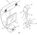
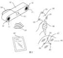
本発明は、一般に、(延長マーカ20によって)基準(22)を感知する光学追跡システム(10)を含む高速光学追跡に関する。基準(それぞれマーカ)は、操作者(例えば外科医)(50)によって扱われるツール(20)上に統合されるか、または追跡されるオブジェクト/被験物(例えば患者)(40)上に固定される。低レベル処理(101、107、140)は追跡システム内で実現されることが好ましい。姿勢データ(127)が計算され、PC/モニタ(30、31)またはタブレット(60)に転送されてエンドユーザアプリケーション(130)によって使用される。 The present invention relates generally to high-speed optical tracking including an optical tracking system (10) sensing fiducials (22) (via extended markers 20). The fiducials (respectively markers) are either integrated onto the tool (20) handled by the operator (eg surgeon) (50) or fixed onto the tracked object/subject (eg patient) (40). . Low level processing (101, 107, 140) is preferably implemented within the tracking system. Attitude data (127) is calculated and transferred to the PC/monitor (30, 31) or tablet (60) for use by the end-user application (130).
したがって、本発明の詳細な説明をよりよく理解するために、また当技術分野に対する現在の貢献をよりよく理解するために、本発明のいくつかの特徴をかなり広く概説した。以下に説明する本発明の多くの追加の特徴がある。 Thus, rather broadly, certain features of the present invention have been outlined in order that the detailed description of the invention may be better understood, as well as its present contributions to the art. There are many additional features of the invention that are described below.
この点に関して、本発明の少なくとも1つの実施形態を詳細に説明する前に、本発明は、その適用において、以下の説明に記載されるかまたは以下の図面に示される構造の詳細または構成要素の配置に限定されないことを理解されたい。本発明は、他の実施形態が可能であり、異なる実施形態にしたがって様々な方法で実施および実行することができる。また、本明細書で使用されている表現および用語は説明の目的のためであり、限定と見なされるべきではないことを理解されたい。 In this regard, before describing at least one embodiment of the invention in detail, the invention may, in its application, be subject to the details of construction or components set forth in the following description or illustrated in the following drawings. It should be understood that the arrangement is not limited. The invention is capable of other embodiments and of being practiced and carried out in various ways according to different embodiments. Also, it is to be understood that the phraseology and terminology used herein is for the purpose of description and should not be regarded as limiting.
第1の態様において、本発明の目的および目的は、既知の装置および方法を改良することである。 SUMMARY OF THE INVENTION In a first aspect, it is an object and object of the present invention to improve known devices and methods.
別の目的は、姿勢(配向および位置)データを配信するときに高速および/または低遅延を必要とする追跡用途のための、圧縮および/またはCMOSウィンドウイングを用いた高速光学追跡を提供することである。 Another object is to provide fast optical tracking with compression and/or CMOS windowing for tracking applications requiring high speed and/or low latency when delivering attitude (orientation and position) data. is.
別の目的は、追跡速度を改善し、姿勢データ配信の遅延を短縮する、圧縮および/またはCMOSウィンドウイングを用いた高速光学追跡を提供することである。 Another object is to provide fast optical tracking with compression and/or CMOS windowing to improve tracking speed and reduce latency in attitude data delivery.
他の目的は、(これらの特徴を持たないであろう)従来の解決策に対して処理されるべきデータが少ないので、埋め込み処理内で高速/低遅延を可能にする圧縮および/またはCMOSウィンドウイングを用いた高速光学追跡を提供することである。 Another object is compression and/or CMOS windowing to allow high speed/low latency within the embedded process, since less data has to be processed for conventional solutions (which would not have these features). Another object is to provide high-speed optical tracking using ing.
別の目的は、圧縮形式で生データを転送し処理することを可能にする、圧縮および/またはCMOSウィンドウイングを用いた高速光学追跡を提供することである。 Another object is to provide high-speed optical tracking with compression and/or CMOS windowing that allows raw data to be transferred and processed in compressed form.
別の目的は、撮像センサの読み出し段階をスピードアップするために、CMOSウィンドウイングおよび画像ベースのオブジェクト追跡を使用する、圧縮および/またはCMOSウィンドウイングを用いた高速光学追跡を提供することである。 Another object is to provide fast optical tracking with compression and/or CMOS windowing using CMOS windowing and image-based object tracking to speed up the readout phase of the imaging sensor.
別の目的は、光分野用途(例えば、2D画像と3D深度マップの同時取得)を可能にするために画像センサの前面に追加のマイクロレンズアレイを使用する、圧縮および/またはCMOSウィンドウイングを用いた高速光学追跡を提供することである。 Another goal is to use compression and/or CMOS windowing using an additional microlens array in front of the image sensor to enable optical field applications (e.g. simultaneous acquisition of 2D images and 3D depth maps). to provide fast optical tracking.
他の目的は、従来の解決法に関してデータ取得をスピードアップするための、圧縮および/またはCMOSウィンドウイングを用いた高速信号処理を提供することである。 Another object is to provide fast signal processing with compression and/or CMOS windowing to speed up data acquisition with respect to conventional solutions.
本発明の他の目的および利点は読者にとって明らかとなり、これらの目的および利点は本発明の範囲内にあることが意図される。上記および関連する目的を達成するために、本発明は添付の図面に示された形態で具体化されてもよいが、図面は例示的なものにすぎず、本明細書に記載の例示的な実施形態に限定されない、本出願の範囲内で図示および説明されている、特定の構成に変更が加えられ得ることに留意されたい。 Other objects and advantages of the invention will become apparent to the reader and are intended to be within the scope of the invention. To the accomplishment of the foregoing and related ends, the present invention may be embodied in the form shown in the accompanying drawings, which are illustrative only and include the exemplary embodiments described herein. It should be noted that modifications may be made to the specific configurations shown and described within the scope of this application, which is not limited to the embodiments.
一実施形態では、本発明は、光学基準およびマーカを高速で追跡する方法に関する。
-)少なくとも1つの基準が、オブジェクト上および/または人上に配置されたマーカに取り付けられ、前述の基準が、少なくとも1つの光学センサによって検出され、前述の光学センサが、センサデータを提供し、
-)前述の光学センサによって検出された前述のマーカの位置および/または配向は、前述のセンサデータのデータ処理ステップによって決定され、
-)前述の決定された位置および/または配向は、処理済みデータとして通信手段を介してさらなる処理のためにアプリケーションに送信され、
前述のデータ処理ステップにおいて、前述のセンサデータは、前述のセンサデータを圧縮するための圧縮モジュールに転送され、前述のマーカの前述の位置および/または配向は、前述の圧縮データから決定される。In one embodiment, the invention relates to a method for fast tracking of optical fiducials and markers.
-) at least one fiducial attached to markers placed on the object and/or on the person, said fiducial being detected by at least one optical sensor, said optical sensor providing sensor data;
-) the position and/or orientation of said marker detected by said optical sensor is determined by a data processing step of said sensor data;
-) said determined position and/or orientation is transmitted as processed data to an application for further processing via communication means;
In said data processing step, said sensor data are transferred to a compression module for compressing said sensor data, and said positions and/or orientations of said markers are determined from said compressed data.
一実施形態では、センサデータ読み出しは部分的であり、センサデータの一部のみが読み出され、その後の処理に使用されることを意味し、それによって前述の読み出しは追跡されるべき基準の決定に十分な情報を含む。 In one embodiment, the sensor data readout is partial, meaning that only a portion of the sensor data is read out and used for subsequent processing, whereby said readout determines the criteria to be tracked. contains enough information to
一実施形態では、前述の基準の部分センサデータは、前述のマーカの前述の位置および/または配向を決定するために圧縮されていない。 In one embodiment, said reference partial sensor data is uncompressed to determine said position and/or orientation of said marker.
本発明の実施形態では、データは圧縮されていてもいなくてもよく、および/または部分的であってもなくてもよい。好ましくは、取得されたデータは処理され(例えば、圧縮されおよび/または部分的な、すなわちウィンドウ化され)、データの全体サイズを縮小し、処理時間を短縮する。 In embodiments of the invention, the data may or may not be compressed and/or may or may not be partial. Preferably, the acquired data is processed (eg, compressed and/or partially or windowed) to reduce the overall size of the data and reduce processing time.
一実施形態では、本方法のデータ処理ステップにおいて、圧縮データまたは非圧縮データは、ピクセルの強度に応じてセグメント化される。 In one embodiment, in the data processing step of the method, the compressed or uncompressed data is segmented according to pixel intensity.
一実施形態では、データのセグメンテーション後に、ブロブがセグメント化画像内で検出され、それらの位置が決定される。 In one embodiment, after segmentation of the data, blobs are detected within the segmented image and their positions are determined.
一実施形態では、3D再構築ポイントクラウドとオブジェクトのジオメトリとの間でジオメトリマッチングが行われる。 In one embodiment, geometry matching is performed between the 3D reconstructed point cloud and the geometry of the object.
一実施形態では、データのさらなる処理は、前述の光学基準および/またはマーカを追跡するためのナビゲーションアプリケーションを含む。 In one embodiment, further processing of the data includes navigation applications for tracking the aforementioned optical fiducials and/or markers.
一実施形態では、データはロボット構造を制御するために使用される。 In one embodiment, the data is used to control robotic structures.
一実施形態では、ロボット構造は外科手術用途に使用される。 In one embodiment, the robotic structure is used for surgical applications.
一実施形態では、ロボット構造は外科医などの操作者によって保持される。例えば、ロボット構造は、Smith Nephew社により製造され、例えば以下のリンクに開示されているNAVIO(商標)手術システムのようなインテリジェントツールであり得る。http://www.smith-nephew.com/professional/microsites/navio/ In one embodiment, the robotic structure is held by an operator, such as a surgeon. For example, the robotic structure can be an intelligent tool such as the NAVIO™ Surgical System manufactured by Smith Nephew and disclosed at the link below. http://www. smith-nephew. com/professional/microsites/navio/
他のロボットおよび装置ももちろん本発明を使用することができ、この例は限定的ではない。 Other robots and devices can of course use the present invention, and this example is not limiting.
本発明はまた、前述の請求項のいずれか1項に記載の光学基準およびマーカを高速追跡するための装置に関し、装置は、
-)オブジェクトおよび/または人上に配置されたマーカに取り付けられた少なくとも1つの基準と、
-)センサデータを介して前述の基準または前述のマーカを検出する光学センサを有する光学追跡システムと、
-)前述のセンサによって検出された前述のマーカの位置および/または配向をセンサデータの処理によって決定するための少なくともメモリおよびセンサデータ処理手段を含む電子的手段と、
-)前述のマーカの前述の決定された位置および/または配向をさらなる処理のためにアプリケーションに転送するための通信手段と、を含み、
前述のデータ処理手段は、
前述のセンサデータを圧縮するための少なくとも1つの圧縮モジュールを含み、前述のマーカの前述の位置および/または配向は、前述の処理手段によって前述の圧縮データから決定される。The invention also relates to a device for fast tracking of optical fiducials and markers according to any one of the preceding claims, the device comprising:
-) at least one fiducial attached to a marker placed on an object and/or person;
-) an optical tracking system having an optical sensor that detects said fiducial or said marker via sensor data;
-) electronic means comprising at least memory and sensor data processing means for determining the position and/or orientation of said marker detected by said sensor by processing sensor data;
-) communication means for transferring said determined position and/or orientation of said marker to an application for further processing;
The aforementioned data processing means are
comprising at least one compression module for compressing said sensor data, said positions and/or orientations of said markers being determined from said compressed data by said processing means;
一実施形態では、前述の処理手段は、前述のセンサのウィンドウから部分センサデータを受け取る。 In one embodiment, said processing means receives partial sensor data from a window of said sensor.
一実施形態では、装置は、前述の決定された位置および/または配向を受け取る電子機器を含み、前述の電子機器はコンピュータ装置である。 In one embodiment, the device includes an electronic device that receives said determined position and/or orientation, said electronic device being a computing device.
一実施形態では、コンピュータ装置はタブレットまたは他の同等の装置である。 In one embodiment, the computing device is a tablet or other equivalent device.
一実施形態では、オブジェクトはマーカである。 In one embodiment, the object is a marker.
一実施形態では、データの転送は無線手段を介して行われる。もちろん、伝送は、有線または有線と無線の組み合わせを介しても行われ得る。 In one embodiment, the transfer of data is via wireless means. Of course, transmission can also be via wires or a combination of wires and wireless.
一実施形態では、光学センサは少なくとも1つのカメラを備える。 In one embodiment, the optical sensor comprises at least one camera.
一実施形態では、装置はロボット構造を制御するために使用される。 In one embodiment, the device is used to control a robotic structure.
一実施形態では、ロボット構造は外科手術用途に使用される。 In one embodiment, the robotic structure is used for surgical applications.
一実施形態では、ロボット構造はインテリジェントツールであり、外科医などの操作者によって保持されてもよい。ロボット構造は、上記で開示されたNavio(商標)外科手術システムまたは別の同等の構造/装置であり得る。 In one embodiment, the robotic structure is an intelligent tool and may be held by an operator such as a surgeon. The robotic structure may be the Navio™ surgical system disclosed above or another equivalent structure/device.
一実施形態では、方法および装置で使用される少なくとも1つの光学センサはプレノプティックカメラであり得る。 In one embodiment, at least one optical sensor used in the method and apparatus can be a plenoptic camera.
一実施形態では、プレノプティックカメラは、センサアレイの前に配置されたマイクロレンズアレイを備えることができ、各マイクロレンズおよびセンサアレイ上で下にあるピクセルは、マイクロカメラを形成する。 In one embodiment, a plenoptic camera may comprise a microlens array positioned in front of a sensor array, with each microlens and underlying pixel on the sensor array forming a microcamera.
一実施形態では、本方法で読み取られる部分センサデータは、特定のマイクロカメラピクセルのみを検索するように定義され得る。 In one embodiment, the partial sensor data read in this method may be defined to search only for specific micro-camera pixels.
一実施形態では、少なくとも1つのマイクロカメラからの情報を使用して、画像内の基準の大まかな位置を定義することができる。 In one embodiment, information from at least one microcamera can be used to define the rough location of fiducials within the image.
本発明の実施形態のすべての技術的手段は、以下の本発明の説明およびその特徴においてより詳細に説明されるであろう。 All technical means of embodiments of the present invention will be described in more detail in the following description of the invention and its features.
本発明の他の様々な手段、目的、特徴、および付随する利点は、添付の図面と併せて考慮すると、よりよく理解され、十分に理解されるであろう。ここで、同じ参照符号は、いくつかの図面において同じまたは類似の部分を示す。 Various other means, objects, features and attendant advantages of the present invention will be better understood and appreciated when considered in conjunction with the accompanying drawings. Here, same reference numerals indicate the same or similar parts in the several drawings.
A.概要
ここで図面を説明的に参照すると、いくつかの図を通して同様の参照符号は同様の要素を示しており、これらの図は、基準(22)を感知する光学追跡システム(10)を示している。マーカ(20)は、既知の位置に互いに固定された3つ以上の基準によって形成されている。マーカは、操作者(例えば、外科医、またはロボット)(50)によって保持されるツール(20)内に/上に統合されるか、または追跡するオブジェクト/被験物(例えば患者)(40)上に固定され得る。低レベル処理(101、107、140)は追跡システム内で実現されることが好ましい。姿勢データ(127)は、内部で計算されてタブレット(60)に送信されるか、または外部のPC(30)に転送されて計算される。姿勢は最終的にエンドユーザアプリケーションによって使用される(130)。システム全体は、例えば処理中に転送するデータ量を減らすことによって、全体の性能を改善する(例えば、速度を改善する、待ち時間を短縮する)ように設計され、それによって時間を勝ち取る。A. Overview Referring now descriptively to the drawings, like reference numerals denote like elements throughout the several views, these figures show an optical tracking system (10) sensing a fiducial (22). there is The marker (20) is formed by three or more fiducials fixed together at known positions. Markers are integrated into/on a tool (20) held by an operator (e.g., surgeon or robot) (50) or on a tracked object/subject (e.g., patient) (40). can be fixed. Low level processing (101, 107, 140) is preferably implemented within the tracking system. Attitude data (127) is either calculated internally and sent to the tablet (60) or transferred externally to the PC (30) for calculation. The pose is ultimately used by the end-user application (130). The overall system is designed to improve overall performance (eg, improve speed, reduce latency), eg, by reducing the amount of data transferred during processing, thereby winning time.
B.光学追跡システム
光学追跡システムは1つ以上のカメラ(11)を含む。装置は、例えば各赤外線カメラを囲むIR LEDを使用して、リング(12)から赤外線を放出する。カメラは、マーカ(20、21)のように、追跡すべきオブジェクト/被験物上に配置された基準(22)を感知している。基準には主に2つのタイプがあり、どちらも本発明の実施形態において代替の解決策として、または組み合わせて可能である。B. Optical Tracking System The optical tracking system includes one or more cameras (11). The device emits infrared radiation from a ring (12), for example using IR LEDs surrounding each infrared camera. The camera senses fiducials (22) placed on the object/subject to be tracked, like markers (20, 21). There are two main types of criteria, both of which are possible as alternative solutions or in combination in embodiments of the present invention.
1.基準を赤外画像において明るいスポットとして出現させる、(例えば、リング12のIR LEDからの)光をレンズに映し出す小さい球体を含む再帰反射材料で被覆された受動的基準。
2.光源(例えば、赤外発光ダイオード-IR-LED)である能動基準。そのような基準を排他的に使用するとき、リング(12)は必要ではない。1. A passive fiducial coated with a retroreflective material containing a small sphere that projects light (eg, from an IR LED in ring 12) into a lens, causing the fiducial to appear as a bright spot in the infrared image.
2. An active reference that is a light source (eg infrared light emitting diode - IR-LED). Ring (12) is not necessary when using such criteria exclusively.
生データはさらに処理され(101、107、140)、基準の3D位置が提供される。3つ以上の検出された基準がマーカの一部であるとき、それらの姿勢を計算することが可能である。 The raw data is further processed (101, 107, 140) to provide 3D positions of reference. When more than two detected fiducials are part of a marker, it is possible to compute their poses.
最も一般に使用されている追跡システムは、ベースラインに固定されたステレオカメラ(2台のカメラで構成されたシステム)である。一方のカメラから他方のカメラへの変換は通常、工場で較正されるか、あるいは現場で較正される。基準が両方のカメラによって同時に検出されると、三角測量によってその3D位置を計算することが可能である。通常に使用される受動光学追跡システムの例は、例えば、Atracsys infiniTrack(商標)、fusionTrack(商標)、spry Track(商標)、Northern Digital Polaris(商標)、およびAxios CamBar(商標)である。 The most commonly used tracking system is a stereo camera (two-camera system) fixed at the baseline. The conversion from one camera to the other is typically factory calibrated or field calibrated. Once a fiducial is detected by both cameras simultaneously, it is possible to calculate its 3D position by triangulation. Examples of commonly used passive optical tracking systems are, for example, Atracsys infiniTrack™, fusionTrack™, spry Track™, Northern Digital Polaris™, and Axios CamBar™.
光学追跡システムは通常近赤外スペクトルで動作するが、代わりに可視スペクトルまたは他のスペクトル用に設計されている。 Optical tracking systems typically operate in the near-infrared spectrum, but are instead designed for the visible spectrum or other spectrums.
光学追跡システムは、代わりにタグまたは既知のパターンを検出することができる。ClaroNav社のARToolkit(商標)(http://artoolkit.org)またはMicronTracker(商標)などのシステムは、特定のタグを持つオブジェクトを追跡している。タグ/パターンは基準と見なされない。タグ/パターンには特徴点がある(ウィキペディアの特徴点を参照)。そして、これらの特徴点は基準を形成するが、本発明の文脈ではタグ/パターンはマーカと見なされる。他の同等のマーキング手段(基準またはマーカ)ももちろん本発明の範囲内で可能である。 Optical tracking systems can alternatively detect tags or known patterns. Systems such as ClaroNav's ARToolkit™ (http://artoolkit.org) or MicronTracker™ track objects with specific tags. Tags/patterns are not considered criteria. Tags/patterns have minutiae points (see Wikipedia minutiae points). And while these feature points form the reference, the tags/patterns are considered markers in the context of the present invention. Other equivalent marking means (fiducials or markers) are of course possible within the scope of the invention.
本発明の他の実施形態では、3つ以上のカメラを有する光学追跡システムが代替的に可能である。 Optical tracking systems with more than two cameras are alternatively possible in other embodiments of the invention.
単一の追跡カメラを部屋に固定し、それぞれの変換を定義するための追加の較正ステップを使用するなど、他の種類のセットアップも可能である。この方法は通常、モーションキャプチャアプリケーションに使用される。あるいは、部屋に複数のカメラ追跡システムを(既知のベースラインで)固定することも可能である。 Other types of setups are possible, such as using a single tracking camera fixed in the room and an additional calibration step to define each transform. This method is commonly used for motion capture applications. Alternatively, it is possible to have multiple camera tracking systems fixed (with a known baseline) in the room.
能動的基準を捕捉するシステム(例えば、赤外線LED)は、図1および図2に記載されたLEDのリング(12)を有する必要はないが、標準製品を提供するために存在し得る(しかし使用されない)。 A system that captures an active reference (e.g., infrared LEDs) need not have the ring of LEDs (12) described in FIGS. 1 and 2, but may be present (but use not).
光学追跡システムは、埋め込み処理能力(例えば、図2)または委任処理(例えば、図1)を有することができる。委任処理により、生信号からの姿勢計算は部分的に追跡システム内でそして部分的にはPCのような外部CPU上で実現される。状況に応じてどちらか一方の構成を選択することができる。 Optical tracking systems can have embedded processing capabilities (eg, FIG. 2) or delegated processing (eg, FIG. 1). By delegating processing, attitude computation from raw signals is implemented partly within the tracking system and partly on an external CPU, such as a PC. Either configuration can be selected depending on the situation.
C.被追跡ツール
被追跡ツールは、器具(20)に堅固に固定された(それぞれ一体化された)マーカを含む。マーカ(文献では剛体とも呼ばれる)(20、21)は、堅固に固定されたいくつかの基準(22)を含む。マーカを形成する基準の相対位置はジオメトリと呼ばれ、3Dポイントクラウドからマーカの姿勢を推定するためにはよく知られている。追跡プロセス(140)の間に、これらの基準が検出され(142)、識別され(143)、それらの3D位置が三角測量によって追跡システムによって計算される(144)。少なくとも3つの基準が検出された場合、関係の追跡システムにおけるマーカの姿勢(位置+並進)を計算するために、アルンレジストレーションアルゴリズム(「2つの3-Dポイントセットの最小二乗フィッティング」、アルン、1987)を使用することができる。被追跡ツールは3つ未満の基準を含み得ることに留意されたい。この場合、減少した空間情報(6自由度未満)だけが、追跡システムによって、検索することができる。被追跡ツールは、外科手術用途においてオートクレーブ処理されるか、または部分的に/全体的に使い捨てであるように設計されている。C. Tracked Tools Tracked tools include markers rigidly affixed (respectively integrated) to the instrument (20). The markers (also called rigid bodies in the literature) (20, 21) contain several rigidly fixed fiducials (22). The relative positions of the fiducials forming the markers are called geometry and are well known for estimating the pose of markers from 3D point clouds. During the tracking process (140), these fiducials are detected (142), identified (143), and their 3D positions are calculated (144) by the tracking system by triangulation. If at least three fiducials are detected, the Arun registration algorithm (“Least-squares fitting of two 3-D point sets”, Arun, 2003) is used to compute the pose (position + translation) of the marker in the relational tracking system. 1987) can be used. Note that a tracked tool may contain less than three criteria. In this case only reduced spatial information (less than 6 degrees of freedom) can be retrieved by the tracking system. Tracked tools are designed to be autoclaved or partially/totally disposable in surgical applications.
被追跡ツールは、レジストレーションの目的のためのデジタイザ、またはドリル、生検針、または超音波プローブ、内視鏡、CTスキャナ、MRI、ロボット、インテリジェントツールなどのような術中の画像化を含む任意の手術用ツールであり得る。 The tracked tool can be any intraoperative imaging device such as a digitizer for registration purposes, or a drill, biopsy needle, or ultrasound probe, endoscope, CT scanner, MRI, robot, intelligent tool, etc. It can be a surgical tool.
被追跡ツールは、自動、半自動または手動の方法で、人間の操作者(例えば外科医)またはロボット(図6を参照)、インテリジェントツール(図7を参照)によって操作されてもよい。ロボットの一例は、Stryker社製のMako System(商標)である。インテリジェントツールの例は、Smith and NephewのNAVIO(商標)である。 A tracked tool may be operated by a human operator (eg, a surgeon) or a robot (see FIG. 6), an intelligent tool (see FIG. 7), in an automatic, semi-automatic, or manual manner. One example of a robot is the Mako System™ manufactured by Stryker. An example of an intelligent tool is Smith and Nephew's NAVIO™.
D.PCシステム
ナビゲーションPC(30)とも呼ばれるPCシステムは、処理済みデータ(32)を検索し、このプロセスが追跡システム(13)内でまだ行われていない場合、マーカ(20、21)の姿勢を計算する。PCは、(タッチ)スクリーン(31)に接続され(33)、エンドユーザアプリケーション(130)を表示する。D. PC System The PC system, also called Navigation PC (30), retrieves the processed data (32) and, if this process has not already taken place in the tracking system (13), computes the poses of the markers (20, 21). do. The PC is connected (33) to a (touch) screen (31) and displays an end-user application (130).
手術室(OR)で使用される典型的なPCシステム(スクリーンを含む)はカートの上に置かれ、追跡ゾーンを狙うジンバルを有するポールに固定されている。 A typical PC system (including screen) used in an operating room (OR) is placed on a cart and fixed to a pole with a gimbal aimed at the tracking zone.
PCは任意のオペレーティングシステム(Windows、Linux(登録商標)など)を実行できる。 The PC can run any operating system (Windows, Linux, etc.).
PC用の入力装置は、タッチスクリーン、マウス、キーボード、Kinectなどの任意の適切なシステムである。 The input device for the PC is any suitable system such as touch screen, mouse, keyboard, Kinect.
E.追跡被験物
追跡被験物(40)は通常、手術を受けている患者である。マーカ(21)は、外科手術の対象となる解剖学的構造上に(できるだけ堅固に)固定される。例えば、股関節置換術中に、マーカをスタインマンネイルに固定することができる。E. Follow-up Subjects Follow-up subjects (40) are typically patients undergoing surgery. The marker (21) is fixed (as rigidly as possible) on the surgically targeted anatomy. For example, a marker can be secured to the Steinmann nail during hip replacement surgery.
異なる外科的処置は、インプラント配置、画像誘導手術、神経、ENT、脊椎、顎顔面、肝臓外科、歯科のようにナビゲーションを使用し、そして本発明から利益を得ることができる。マーカ(21)が、追跡するために、解剖学的構造上に固定(ねじ止め、テープ止めなど)される。レジストレーションステップが実現された後、マーカは解剖学的構造に固定されたままでなければならず、そうでなければ再レジストレーションが必要である。 Different surgical procedures use navigation, such as implant placement, image-guided surgery, neurological, ENT, spine, maxillofacial, liver surgery, dental, and can benefit from the present invention. A marker (21) is fixed (screwed, taped, etc.) onto the anatomy for tracking. After the registration step is accomplished, the markers must remain fixed to the anatomy, otherwise re-registration is required.
F.操作者
操作者(50)は追跡された器具を保持する。図1の用途では、外科医はデジタイザ(20)を使用して解剖学的ランドマークを患者(40)に向ける。外科手術用途において、操作者は外科医、助手および/または看護師である。操作者は、インテリジェントツールの場合、ロボットまたはその両方の組み合わせでもよい。F. Operator The operator (50) holds the tracked instrument. In the application of FIG. 1, the surgeon uses the digitizer (20) to orient anatomical landmarks toward the patient (40). In surgical applications, the operator is the surgeon, assistant and/or nurse. The operator may be a robot or a combination of both in the case of intelligent tools.
G.タブレット
タブレット(60)は、データ転送(61)が通常無線で行われることを除いて、タッチスクリーンを有するPCと同様である。G. Tablets Tablets (60) are similar to PCs with touch screens, except that data transfer (61) is usually wireless.
タブレットは、ポータブルPC(例えば、Lenovo Yoga(登録商標))、ファブレット(Android(登録商標)、iOS(登録商標)、Windows(登録商標))、タブレット(iPad(登録商標))、またはタッチスクリーンを含む任意のモバイルコンピュータであり得る。 The tablet may be a portable PC (e.g., Lenovo Yoga®), phablet (Android®, iOS®, Windows®), tablet (iPad®), or touch screen can be any mobile computer, including
タブレットは通常医療グレードであり、かつ/または手術室の滅菌領域内の汚染を避けるために滅菌バッグに包まれている。 Tablets are usually medical grade and/or packaged in sterile bags to avoid contamination within the sterile area of the operating room.
H.カメラセンサ
カメラセンサ(11)は、画像センサとそれを制御するための電子機器とを備える。例えば、CMOS(相補型金属酸化膜半導体)画像センサ(100)は、光を電荷に変換し、それを電子信号に処理する。この技術では、各ピクセルが独自の電荷-電圧変換を行い、センサにはアンプ、ノイズ補正、デジタル化回路も含まれるため、チップ出力はデジタルビットになる。CMOSイメージャはピクセルで電荷を電圧に変換し、ほとんどの機能はチップに統合されている。CMOS技術は、画像の一部のみを読み出す能力(ウィンドウイング機構とも呼ばれる)を有する(106)。この技術は、小さな関心領域(ピクセル)のみが読み出されるので、全体のフレームレートを増大させ、待ち時間を減らすために使用され、本発明では典型的に使用され得る。H. Camera Sensor The camera sensor (11) comprises an image sensor and electronics for controlling it. For example, a CMOS (Complementary Metal-Oxide-Semiconductor) image sensor (100) converts light into electric charge and processes it into electronic signals. With this technology, each pixel performs its own charge-to-voltage conversion, and the sensor also includes amplifier, noise correction, and digitization circuitry, so the chip output is a digital bit. CMOS imagers convert charge to voltage at pixels and most of the functionality is integrated on the chip. CMOS technology has the ability to read out only a portion of the image (also called a windowing mechanism) (106). This technique is used to increase the overall frame rate and reduce latency, as only small regions of interest (pixels) are read out, and can typically be used in the present invention.
センサは、チップを制御する(例えば、インテグレーション時間を設定する、ピクセル深度検索を設定するなど)だけでなく、画像(101)内の基準(22)の位置を推定する、専用のデジタル電子機器にリンクされ、CMOSセンサ内の対応する関心領域(ウィンドウ)を設定する。スマートウィンドウイングのヒューリスティックは、より少ないピクセルが読み出されるので、CMOSセンサの読み出し時間を典型的には1.5から3倍の範囲で短縮することができ、これにより全体的な取得プロセスをかなりスピードアップすることが可能になる。ヒューリスティックの例は、本明細書において後に提示され、本発明の実施形態において適用され得る。 The sensors are dedicated digital electronics that not only control the chip (e.g. set the integration time, set the pixel depth search, etc.), but also estimate the position of the fiducial (22) within the image (101). linked to set a corresponding region of interest (window) in the CMOS sensor. Smart windowing heuristics can reduce the readout time of a CMOS sensor, typically in the range of 1.5 to 3 times, as fewer pixels are read out, thereby significantly speeding up the overall acquisition process. be able to go up. Examples of heuristics are presented later in this specification and may be applied in embodiments of the invention.
ウィンドウイング機能を有する任意の画像センサ技術が、代わりに本発明の実施形態において使用されてもよい。 Any image sensor technology with windowing capabilities may alternatively be used in embodiments of the present invention.
画像センサから読み出された部分画像はさらに圧縮される(107)。画像圧縮アルゴリズムは、画像の(任意の/完全な)解凍を必要とせずに画像セグメンテーションプロセス(141)を実行できるように設計されている。得られた圧縮画像はさらに共有メモリ(110)に転送される(108)。 The partial images read out from the image sensor are further compressed (107). Image compression algorithms are designed such that the image segmentation process (141) can be performed without requiring (any/complete) decompression of the image. The resulting compressed image is further transferred (108) to the shared memory (110).
カメラセンサは、マイクロコントローラまたはFPGA制御回路に接続されたCMOS画像センサを含み得る。CMOSを制御するための電子機器は、代わりにチップ上に埋め込まれてもよい(ASIC)。カメラセンサは、このタスクのために完全に設計されてもよく、それは、それが有効ピクセル配列、ウィンドウイング機能、および低レベル追跡エンジン(101)を含むことを意味する。 A camera sensor may include a CMOS image sensor connected to a microcontroller or FPGA control circuit. The electronics for controlling CMOS may alternatively be embedded on the chip (ASIC). A camera sensor may be perfectly designed for this task, meaning it includes an effective pixel array, a windowing function, and a low-level tracking engine (101).
カメラレンズは、古典的なメインレンズを含んでもよく、または画像センサがシーンの2D画像および3D深度情報を単一のキャプチャで記録することを可能にする追加のマイクロレンズアレイで構成されてもよい(例えば、https://raytrix.de/technology/、https://www.lytro.com)。画像センサの前に追加のマイクロレンズアレイを配置することは、センサ上に捕捉された光を修正する。各単一のマイクロレンズはセンサ上に単一の画像を作成し、その画像のサイズは各単一のマイクロレンズ(マイクロカメラとしても知られる)の後ろのピクセルのサイズに等しい。そのキャプチャされたサブ画像は、特定の画角のシーンを示す。センサ上のその画像の設置面積は、マイクロレンズのサイズに制限されている。その場合、独自のマイクロレンズからピクセルを部分的に読み出すことで、シーンの完全な2D概観図にアクセスできる。この種のレンズは、低レベル追跡エンジンがウィンドウイングアルゴリズムを微調整するのを助けるために、追跡システム上、1つまたは複数のカメラ上に取り付けることができる。ウィンドウイングアルゴリズムは、その部分読み出しを使用して、より低い解像度でも完全な視野を視覚化することができる。ノイズの多い視野は、事前定義された限られた読み出し時間で簡単に識別できる。 The camera lens may include the classical main lens, or may consist of an additional microlens array that allows the image sensor to record 2D images of the scene and 3D depth information in a single capture. (eg https://raytrix.de/technology/, https://www.lytro.com). Placing an additional microlens array in front of the image sensor modifies the light captured on the sensor. Each single microlens creates a single image on the sensor, and the size of that image is equal to the size of the pixels behind each single microlens (also known as a microcamera). The captured sub-image shows the scene at a particular angle of view. The footprint of that image on the sensor is limited to the size of the microlens. In that case, a complete 2D overview of the scene can be accessed by partially reading out the pixels through the unique microlenses. This type of lens can be mounted on one or more cameras on the tracking system to help the low-level tracking engine fine-tune the windowing algorithm. A windowing algorithm can use its partial readout to visualize the full field of view even at lower resolutions. Noisy fields of view can be easily identified with a limited pre-defined readout time.
そのような明視野(別名プレノプティック)カメラは、とりわけ、撮影後の被写界深度の再焦点合わせを可能にする。ウィンドウイングアルゴリズムは、一意の単一のキャプチャからキャプチャされた各部分データについてシーンの焦点をその場で再構成することができる。ブロブの光学的ジッタまたはそのサイズ、その相対距離、または見られる3Dマーカの画角などの異なる基準を考慮することができる。 Such bright-field (aka plenoptic) cameras allow, among other things, depth-of-field refocusing after taking a picture. The windowing algorithm can reconstruct the scene focus on the fly for each partial data captured from a unique single capture. Different criteria such as the optical jitter of the blob or its size, its relative distance, or the angle of view of the 3D marker viewed can be considered.
そのレンズは、IR限定、または可視スペクトル範囲の画像センサに取り付けてもよい。3D深度情報を分析せずに処理できるのは、2D画像の部分データまたは完全データのみである。限られた解像度でも、3D深度情報は部分的に再構築できる。 The lens may be attached to an IR-limited or visible spectral range image sensor. Only partial or complete data of 2D images can be processed without analyzing 3D depth information. Even with limited resolution, 3D depth information can be partially reconstructed.
その明視野カメラは、他のカメラと同期されているかまたは同期されていない追加のデータソース(2Dおよび/または3D画像)として代わりに使用されてもよい。 The brightfield camera may alternatively be used as an additional data source (2D and/or 3D images) that may or may not be synchronized with other cameras.
他の任意の明視野技術(例えばマルチカメラアレイ)を代わりに使用してもよい。 Any other brightfield technique (eg, multi-camera array) may be used instead.
I.メモリ
メモリ(110)は、カメラセンサモジュール(100)から来る圧縮部分画像を保存する。処理が埋め込まれている場合、メインプロセッサはさらなる処理のためにこれらの部分画像に(内部バスを介して)アクセスする。処理が外部のPCで行われる場合、部分画像データは通信チャネルによってPCに転送される(32)。この通信チャネルは、有線(例えば、USB、イーサネット(登録商標)など)または無線(例えば、Li-Fi、Wi-Fi、Bluetooth(登録商標)など)であり得る。I. Memory The memory (110) stores compressed partial images coming from the camera sensor module (100). If processing is embedded, the main processor accesses these partial images (via an internal bus) for further processing. If the processing is done on an external PC, the partial image data is transferred 32 to the PC via a communication channel. This communication channel can be wired (eg, USB, Ethernet, etc.) or wireless (eg, Li-Fi, Wi-Fi, Bluetooth, etc.).
リアルタイムのデータフローを保存するには高速メモリが必要である。例えば典型的にはRAM(例えばDDR2、DDR3)が使用される。 Fast memory is required to store real-time data flow. For example, RAM (eg, DDR2, DDR3) is typically used.
J.エンドユーザアプリケーション
一般的なエンドユーザアプリケーションは、画像誘導手術、コンピュータ支援手術、またはロボット支援手術専用である。J. End-User Applications Typical end-user applications are dedicated to image-guided surgery, computer-assisted surgery, or robot-assisted surgery.
モーションキャプチャまたはリハビリテーションのための代替用途は、提案された発明から利益を得ることができる。 Alternative applications for motion capture or rehabilitation can benefit from the proposed invention.
品質管理およびリバースエンジニアリングの分野における代替の産業用途もまた想定され得る。 Alternative industrial applications in the field of quality control and reverse engineering can also be envisioned.
他の一般的な計測用途も本発明から利益を得ることができる。 Other general metrology applications can also benefit from the present invention.
K.圧縮部分画像処理
圧縮部分画像処理(140)の目的は、最小限のCPU資源を用いて可能な限り高速に生の圧縮部分画像からマーカ(146)の姿勢推定を計算することである。全体的なプロセスは文献でよく知られており、例えば以下の論文に見出すことができる。Tomas Pintaric、2007の「仮想現実および拡張現実のための手ごろな価格の赤外線光学姿勢追跡」は、参照により本出願に組み込まれる。提案されたアプローチの独創性は、画像データを予備的に解凍することを必要とせずに処理を実行することである。データの転送と処理に必要な帯域幅が少なくて済むため、更新速度が向上し、全体的な待ち時間が短縮される。K. Compressed Sub-Image Processing The purpose of the compressed sub-image processing (140) is to compute the pose estimate of the marker (146) from the raw compressed sub-images as fast as possible using minimal CPU resources. The overall process is well known in the literature and can be found, for example, in the following papers. Tomas Pintaric, 2007, "Affordable Infrared Optical Attitude Tracking for Virtual and Augmented Reality," is incorporated herein by reference. The originality of the proposed approach is that it performs the processing without the need to pre-decompress the image data. Less bandwidth is required to transfer and process data, resulting in faster updates and lower overall latency.
処理は基本的に次のように定義することができる:ブロブを見つけるために圧縮部分画像が最初にセグメント化される(141)。ブロブは通常、基準の画像である(ただし、代替的にノイズの場合もある)。そのような圧縮アルゴリズムの例は、本明細書において後述される。次に、各候補ブロブの重心(142)が標準的な画像処理技術を使用して計算される。ブロブは、それらがどの基準/マーカからのものであるかを決定するためにさらに識別される(143)。カメラセンサのジオメトリ(内因性および外因性パラメータ)(100)が分かっているので、三角測量(144)によって各基準の3D位置を見つけることが可能である。システムはさらに、これらの再構成された3Dポイント内でマーカのジオメトリを見つけようと試みる(145)。最後に、マーカの姿勢(配向および位置)および/または個々の基準の3D位置が計算され(146)、さらにエンドユーザアプリケーション(130)に転送される(127)。 The process can basically be defined as follows: the compressed sub-image is first segmented (141) to find the blobs. A blob is usually a reference image (alternatively it may be noise). Examples of such compression algorithms are described later in this specification. The centroid (142) of each candidate blob is then computed using standard image processing techniques. Blobs are further identified (143) to determine from which fiducial/marker they came from. Knowing the camera sensor geometry (intrinsic and extrinsic parameters) (100), it is possible to find the 3D position of each fiducial by triangulation (144). The system further attempts to find the marker geometry within these reconstructed 3D points (145). Finally, the pose (orientation and position) of the markers and/or the 3D positions of the individual fiducials are calculated (146) and forwarded (127) to the end-user application (130).
この処理は、FPGA(フィールドプログラマブルゲートアレイ)、SoC(システムオンチップ)、マイクロコントローラ、CPU、DSPなどの埋め込みプロセッサ内で、または専用のASICチップ内で直接行われる。 This processing takes place in embedded processors such as FPGAs (field programmable gate arrays), SoCs (system on chips), microcontrollers, CPUs, DSPs, or directly in dedicated ASIC chips.
キャプチャされた部分画像データをメモリに移動すると、プラットフォームが提供する複数の最適化を活用できる。典型的な最適化は、メモリに移動されたデータの部分的な各セットに対して割り込み信号をトリガすることである。一組のデータは、単一のブロブを再構成するためのピクセルの集合体であり得る。 Moving the captured partial image data into memory can take advantage of several optimizations provided by the platform. A typical optimization is to trigger an interrupt signal for each partial set of data moved to memory. A set of data can be a collection of pixels to reconstruct a single blob.
処理ユニットは、分離されたハードウェアFPGA回路(事前定義された動作で構成された)を有するSoC FPGA、および画像ブロブ解析などのソフトウェアアルゴリズムを実行するARMベースのHPSなどのハードウェアプロセッサであり得る。その部分データが処理されてメモリにプッシュされる準備ができるとすぐに、FPGAユニットは信号をトリガする。ハードウェア/ソフトウェアプロセッサは、他のブロブ位置を含む他のデータセットを待つ前にそのソフトウェア計算を開始することができる。全体的なプロセスを並列化することもできる。 The processing unit can be a SoC FPGA with a separate hardware FPGA circuit (configured with predefined operations) and a hardware processor such as an ARM-based HPS that executes software algorithms such as image blob analysis. . The FPGA unit triggers a signal as soon as that partial data is processed and ready to be pushed to memory. The hardware/software processor can start its software calculations before waiting for other data sets containing other blob positions. The entire process can also be parallelized.
L.発明の主要要素と下位要素の結合
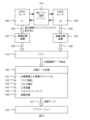
典型的な光学追跡セットアップでは、光学追跡システム(10)の各カメラ(11)は視野内にある基準を感知している。カメラセンサ(通常はCMOS)は、画像内の新しい基準の位置を検出すると共に以前に検出された基準を追跡する低レベル追跡エンジン(101)に接続されている。この動作は、基準が位置すると予想される画像内のいくつかのウィンドウの位置を推定することによって実現される。以下の説明で詳述される章「カメラセンサ画像内のマーカ追跡のためのヒューリスティックの例」は、そのようなアルゴリズムの可能な実施を提示する。部分画像はセンサ(106)から読み出され、さらに画像圧縮モジュール(107)に転送され、それは画像のメモリ占有面積ト(サイズ)を縮小する。この圧縮はまた、部分的/完全な解凍を必要とせずに画像を後で処理することを可能にする(140)。以下の章:「圧縮部分画像内の基準重心を検索するためのアルゴリズムの例」は、そのようなアルゴリズムの可能な実施を提示する。圧縮部分画像はさらにメインメモリ(110)に転送される。処理モジュールは、埋め込み処理(13)の場合には内部信号システムによって、または外部のPC(30)で処理が実現される場合には送信手段(USB、イーサネット(登録商標)、Wi-Fiなど)によって新しいデータが利用可能であることを知らされる。圧縮データ処理ユニット(140)は、まず、データを解凍することなく、圧縮画像を入力として直接使用して、ピクセル(141)の強度に応じて画像をセグメント化し、セグメント化画像からブロブ(142)を検出し、それらの重心を定義し、左右の対応関係を見つけ(143)、三角測量によってそれらの3D位置を決定する(144)。基準点がマーカに固定されている場合、3Dポイントクラウドとマーカのジオメトリとの間の対応はさらに実行される(20、21)。このステップはジオメトリマッチング(145)と呼ばれる。姿勢データが計算され(146)、さらにエンドユーザアプリケーション(130)に転送される(127)。エンドユーザアプリケーションは、インターフェースにしたがって測定値をフォーマットする。例えば、患者(40)に対する生検針の軌跡、デジタイザ(20)の位置などを外科医に知らせる。L. Combining Main Elements and Sub-Elements of the Invention In a typical optical tracking setup, each camera (11) of the optical tracking system (10) senses a fiducial within its field of view. A camera sensor (usually CMOS) is connected to a low-level tracking engine (101) that detects the position of new fiducials in the image and tracks previously detected fiducials. This operation is accomplished by estimating the position of some window in the image where the fiducial is expected to be located. The section "Example Heuristics for Marker Tracking in Camera Sensor Images" detailed in the description below presents a possible implementation of such an algorithm. A partial image is read out from the sensor (106) and further transferred to an image compression module (107), which reduces the memory footprint (size) of the image. This compression also allows later processing of the image without the need for partial/complete decompression (140). The following section: "Example Algorithm for Finding Reference Centroids in Compressed Subimages" presents a possible implementation of such an algorithm. The compressed partial images are further transferred to the main memory (110). The processing module is connected either by an internal signal system in the case of embedded processing (13) or by means of transmission (USB, Ethernet, Wi-Fi, etc.) if the processing is realized on an external PC (30). is notified that new data is available. The compressed data processing unit (140) first uses the compressed image directly as input without decompressing the data to segment the image according to the intensity of the pixels (141) and extracts blobs (142) from the segmented image. , define their centroids, find left-right correspondences (143), and determine their 3D positions by triangulation (144). If the reference points are fixed to the markers, a correspondence between the 3D point cloud and the geometry of the markers is also performed (20, 21). This step is called geometry matching (145). Pose data is calculated (146) and forwarded (127) to the end-user application (130). The end-user application formats the measurements according to the interface. For example, the surgeon is informed of the trajectory of the biopsy needle relative to the patient (40), the position of the digitizer (20), and the like.
M.発明の代替実施形態
本発明がウィンドウイング機構のみを含む場合、それは読み出し時間を短縮することを可能にする。それは、全体的な待ち時間減らし、および/または更新速度を上げる結果を有する。後で説明するように、ウィンドウイングのない一般的な構成は、画像を転送するための通信時間のために32Hzで動作する。いくつかの実験的セットアップから、ウィンドウイング機構を追加すると、基準構成に応じてフレームレートが30%から100%(41.6Hzから64Hz)の間で増加する。M. Alternative Embodiments of the Invention If the invention only includes a windowing mechanism, it makes it possible to shorten the readout time. It has the result of reducing overall latency and/or increasing update speed. As will be explained later, a typical configuration without windowing operates at 32 Hz due to airtime to transfer images. From several experimental setups, adding the windowing mechanism increases the frame rate by between 30% and 100% (41.6 Hz to 64 Hz) depending on the reference configuration.
本発明が圧縮機構のみを含む場合、それは、圧縮なしの32Hzと比較して、より高いフレームレート(典型的には、Atracsys fusionTrack(商標)システムで4msの待ち時間で335Hz)で画像を転送することを可能にする。高フレームレートにより、ロボットシステムの制御ループに光学追跡を統合するなど、新しいタイプのアプリケーションが可能になる。 When the present invention includes only the compression mechanism, it transfers images at a higher frame rate (typically 335 Hz with 4 ms latency on Atracsys fusionTrack™ systems) compared to 32 Hz without compression. make it possible. High frame rates enable new types of applications, such as integrating optical tracking into the control loops of robotic systems.
ウィンドウイングと圧縮機構(オーバードライブモードとも呼ばれる)を組み合わせることで、ミッドレンジのコンポーネントと従来の追跡システムのわずかなハードウェアの変更だけで、ハイエンドシステム(通常、Atracsys fusionTrack(商標)では3msの待ち時間で1000Hz)の性能を得ることができる。これにより、ハードウェア全体のコストを削減できる。 A combination of windowing and a compression mechanism (also called overdrive mode) allows high-end systems (typically 3ms latency 1000 Hz at time) can be obtained. This reduces the overall hardware cost.
本発明の一実施形態では、オーバードライブモードを使用して、従来の単眼またはステレオビデオカメラに追跡機能を追加することができる。従来は、一つの平均グレースケールまたはカラーカメラが、フル画像を取得し、可視および/または近赤外スペクトルで作動する。これらのカメラは、レンズの周囲に照明リングがあってもなくてもよい。この実施形態では、追跡画像は標準カメラ画像間にインターリーブされる。単一カメラ構成では、Dementhon、1995の「25行のコードでモデルベースのオブジェクト姿勢」ようなアルゴリズムを使用して、追跡するオブジェクト/被験物上に位置する4つ以上の基準に基づいて、オブジェクトの姿勢を推定できる。オーバードライブモードを使用することによって、追跡はカメラ電子機器におけるより少ない処理および低い伝送帯域幅を必要とするであろう。そのように、このハイブリッド追跡/従来カメラの全体のフレームレートは、従来のものとほぼ同じフレームレートとなる。他方で、二重追跡と通常の取得が従来のカメラに統合されている場合、(追跡画像全体を圧縮せずに転送する必要があるので)グローバル更新速度は2倍遅くなる。 In one embodiment of the present invention, overdrive mode can be used to add tracking capability to conventional monocular or stereo video cameras. Conventionally, a single average grayscale or color camera captures the full image and operates in the visible and/or near-infrared spectrum. These cameras may or may not have an illumination ring around the lens. In this embodiment, the tracking images are interleaved between standard camera images. In a single-camera configuration, algorithms such as Dementhon, 1995, "Model-based object pose in 25 lines of code," can be used to determine object orientation based on four or more fiducials located on the tracked object/subject. pose can be estimated. By using overdrive mode, tracking will require less processing and lower transmission bandwidth in the camera electronics. As such, the overall frame rate of this hybrid tracking/traditional camera is about the same as the conventional one. On the other hand, if double tracking and normal acquisition are integrated in a conventional camera, the global update rate is doubled (because the entire tracking image has to be transferred uncompressed).
前述の実施形態の適用例は、単一の(あるいはステレオの)カメラによる頭の追跡である。ユーザは複数の基準を取り付けた眼鏡をかけている。オーバードライブモードを有するカメラは、速い更新速度/低い待ち時間で頭の動き(それぞれ目の位置)を追跡することを可能にする。ハイブリッドカメラを使用して同時に画像を追跡し取得することができる。ハイブリッド取得は、眼鏡の追跡とビデオ取得(例えばビデオ会議)とを同時に動作させるために使用され得る。目の位置の推定は、自動立体3Dスクリーンを駆動するために使用され得る。 An example application of the above embodiments is head tracking with a single (or stereo) camera. The user is wearing glasses with multiple fiducials attached. A camera with overdrive mode allows tracking head movements (respectively eye positions) with fast update rate/low latency. A hybrid camera can be used to simultaneously track and acquire images. Hybrid acquisition can be used to simultaneously operate eyeglass tracking and video acquisition (eg, video conferencing). Eye position estimation can be used to drive an autostereoscopic 3D screen.
同様のハイブリッド手法を使用して、頭の上(例えば眼鏡、帽子など)に位置する1つまたは複数の基準を用いてユーザの頭を追跡し、同時に従来の画像に画像処理を使用して目、鼻、口などの他の特徴を検出することができる。これらの新たに検出された特徴は、追跡の初期姿勢推定を改良することを可能にする。あるいは、基準の追跡は、画像内の特徴検出をブートストラップすること、および/またはそれをより速くすることを可能にする。 A similar hybrid approach can be used to track the user's head using one or more fiducials located on the head (e.g. glasses, hat, etc.) while simultaneously using image processing on conventional images to track the eyes. , nose, mouth, etc. can be detected. These newly detected features allow us to refine the initial pose estimate for tracking. Alternatively, tracking fiducials allows bootstrapping feature detection in images and/or making it faster.
本発明の一実施形態では、反射基準を照らすためのリングを有する代わりに、カメラがフォトンを検出しているときにのみLEDがアクティブになるように、アクティブLEDをカメラの取得と無線で同期(光学的同期、Wi-Fi、Bluetooth(登録商標)、Li-Fiなど)することができる。このメカニズムにより、既存のカメラハードウェアを使用するだけで、前述のハイブリッドカメラ(追跡/画像取得)を実現できる。そのようなカメラは、ウェブカム、工業用カメラ、防犯カメラなどであり得る。 In one embodiment of the present invention, instead of having a ring to illuminate a reflective reference, the active LEDs are wirelessly synchronized with the camera's acquisition so that the LEDs are active only when the camera is detecting photons. optical synchronization, Wi-Fi, Bluetooth®, Li-Fi, etc.). This mechanism allows the aforementioned hybrid camera (tracking/image acquisition) to be achieved by simply using existing camera hardware. Such cameras can be webcams, industrial cameras, security cameras, and the like.
本発明の一実施形態では、ハイブリッドカメラはセキュリティ用途に使用される。追跡は、(1つ以上の基準を備えた)オブジェクトが動いたかどうかをチェックするため、または視野内の特定のパラメータ(例えば、床、ドア、制限区域などの位置)を推定するために行われる。 In one embodiment of the invention, the hybrid camera is used for security applications. Tracking is done to check if an object (with one or more criteria) has moved or to estimate certain parameters within the field of view (e.g. position of floor, door, restricted area, etc.) .
本発明の一実施形態では、前述のアクティブ/パッシブ基準を追跡するのではなく、システムは、ウィンドウイング機構を使用して部分画像上で高フレームレートでSIFT(スケール不変特徴変換)特徴を抽出し追跡する。ハイブリッドモードは、部分画像とインターリーブされた完全な画像を取得することを可能にするだろう。両方のレートは独立して(同期的または非同期的に)構成することができる。他の任意の画像特徴(例えば、輪郭/エッジ記述子、カラー/テクスチャ記述子など)も代わりに使用することができる。 In one embodiment of the present invention, rather than tracking the active/passive criteria described above, the system uses a windowing mechanism to extract SIFT (Scale Invariant Feature Transform) features at high frame rates on sub-images. Chase. A hybrid mode will allow obtaining a full image interleaved with partial images. Both rates can be configured independently (synchronously or asynchronously). Any other image feature (eg, contour/edge descriptors, color/texture descriptors, etc.) can be used instead.
本発明の一実施形態では、基準を追跡する代わりに、システムは高速汎用1D信号を捕捉していてもよい(例えば、分光法)。1Dセンサの代わりに、(本発明において提示されるように)2Dセンサを使用することで、処理を並列化すること(例えば、2Dセンサ上に複数の1D信号を有すること)および/または1Dセンサでは不可能な画像センサ上の信号の完全な整列を修正することができて、興味深い。オーバードライブ機構により、全体的な更新速度(データ速度)を上げ、待ち時間を減らすことができる。 In one embodiment of the present invention, instead of tracking fiducials, the system may acquire fast generalized 1D signals (eg, spectroscopy). Using a 2D sensor (as presented in this invention) instead of a 1D sensor parallelizes processing (e.g., having multiple 1D signals on a 2D sensor) and/or It is interesting to be able to correct the perfect alignment of the signals on the image sensor, which is not possible with An overdrive mechanism can increase the overall update rate (data rate) and reduce latency.
本発明の一実施形態では、ウィンドウイングヒューリスティックは、慣性測定ユニット(IMU)のような外部センサによって提供された情報を入力することができる。IMUは、より高いフレームレートで、またはインターリーブデータ取得で機能することができる。このように、ウィンドウイング検索を狭めるために、カメラ参照フレーム内の基準の位置を外挿することが可能である。そのようなアプローチは、検索ゾーン(ウィンドウ)を減らし、検出ヒューリスティックをより頑強にし、そしてより高いフレームレート/より短い待ち時間を可能にするであろう。 In one embodiment of the invention, the windowing heuristic may input information provided by external sensors such as an inertial measurement unit (IMU). The IMU can work at higher frame rates or with interleaved data acquisition. Thus, it is possible to extrapolate the position of the fiducial within the camera reference frame in order to narrow the windowing search. Such an approach would reduce the search zone (window), make detection heuristics more robust, and allow higher frame rates/lower latency.
本発明の一実施形態では、説明した光学追跡システムは医療用ロボット用途に使用することができる。基準点(それぞれマーカ)はロボット上(例えばそのエンドエフェクタ上)および患者上に配置されるであろう。ロボット制御は、処置中の患者の動きをリアルタイムで補償するために、例えば、高速低遅延光学追跡システムからのデータを含むであろう。 In one embodiment of the invention, the optical tracking system described can be used in medical robotic applications. Reference points (markers respectively) will be placed on the robot (eg on its end effector) and on the patient. Robotic control would include data from, for example, a high-speed, low-latency optical tracking system to compensate for patient motion in real-time during treatment.
本発明の一実施形態では、説明した光学追跡システムはインテリジェントツールロボット用途に使用することができる。この構成は、外科医がロボットを握ることを除いて、前のものと非常に似ている。以前の利点に加えて、このセットアップにより、待ち時間が短縮され更新速度が向上するので、外科医はより速く(そしてより自然に)動くことができる。 In one embodiment of the present invention, the optical tracking system described can be used for intelligent tool robotic applications. This configuration is very similar to the previous one, except the surgeon holds the robot. In addition to the previous benefits, this setup allows the surgeon to move faster (and more naturally) as it reduces latency and increases update speed.
本明細書で説明および図示されたものは、その変形のいくつかと共に本発明の好ましい実施形態である。本明細書で使用される用語、説明、および図は、例示としてのみ記載されており、限定を意味するものではない。当業者は、本発明の精神および範囲内で多くの変形が可能であることを理解するであろう。ここで全ての用語は、他に示されない限り、それらの最も広い、合理的な意味で意味される。説明の中で利用されている見出しは、便宜上のものであり、法的または制限的な効果を有しない。 What has been described and illustrated herein is the preferred embodiment of the invention along with some of its variations. The terms, descriptions and figures used herein are set forth by way of illustration only and are not meant as limitations. Those skilled in the art will understand that many variations are possible within the spirit and scope of the invention. All terms herein are meant in their broadest, rational sense unless otherwise indicated. Headings used in the description are for convenience only and have no legal or restrictive effect.
例示的な実施形態は、本明細書に開示されるシステムおよび方法の構造、機能、製造、および使用の原理の全体的な理解を提供するために説明されてきた。これらの実施形態の1つ以上の例が添付の図面に示されている。当業者であれば、本明細書で具体的に説明し添付の図面に示したシステムおよび方法は非限定的な例示的実施形態であり、本発明の範囲は特許請求の範囲によってのみ定義されるのではないことを理解されよう。1つの例示的な実施形態に関連して図示または説明されている特徴は、他の実施形態の特徴と組み合わせることができる。そのような修正形態および変形形態は、本発明の範囲内に含まれることが意図されている。従来の方法およびシステムに関するいくつかの問題が本明細書に記載されており、本明細書に開示されている方法およびシステムは、これらの問題のうちの1つまたは複数に対処することができる。これらの問題を説明することによって、当分野におけるそれらの知識に関する承認は意図されていない。当業者であれば本発明の範囲はそのように限定されないことを理解するであろう。さらに、本発明をいくつかの実施形態と併せて説明してきたが、多くの代替形態、修正形態、および変形形態が、当業者には明らかであろう、または明らかであることは明示的である。したがって、本発明の範囲内にあるそのような全ての代替物、修正物、等価物および変形物を包含することが意図されている。 The exemplary embodiments have been described to provide a general understanding of the principles of construction, function, manufacture, and use of the systems and methods disclosed herein. One or more examples of these embodiments are illustrated in the accompanying drawings. Those skilled in the art will appreciate that the systems and methods specifically described herein and illustrated in the accompanying drawings are non-limiting exemplary embodiments, the scope of the invention being defined solely by the claims. It should be understood that the Features shown or described in connection with one exemplary embodiment may be combined with features of other embodiments. Such modifications and variations are intended to be included within the scope of the present invention. Several problems with conventional methods and systems are described herein, and the methods and systems disclosed herein can address one or more of these problems. By describing these issues, no admission is intended as to their knowledge in the art. Those skilled in the art will appreciate that the scope of the invention is not so limited. Furthermore, while the present invention has been described in conjunction with several embodiments, it is expresses that many alternatives, modifications and variations will be or will be apparent to those skilled in the art. . Accordingly, it is intended to embrace all such alternatives, modifications, equivalents and variations that fall within the scope of the invention.
附属書1:カメラセンサ画像におけるマーカ追跡のためのヒューリスティックの例
外科手術用途におけるロボット工学の使用は増加している。これらの新しい用途は、設計上、コンピュータ支援手術システムの従来の用途よりも待ち時間の制約が大きい。実際、ロボットが時間どおりに外部のイベントに反応するには、より短い待ち時間が必要である。これは、人命が危険にさらされている外科手術用途において特に重要である。Atracsys社のハイエンド追跡ソリューションはfusionTrack(商標)と呼ばれている。330Hz以上で立体画像をストリーミングおよび処理することができる。そのフレームレートはかなり高いが、顧客は4ミリ秒の平均待ち時間がそれらのリアルタイムの要求を満たさないと指摘した。これを3ミリ秒に減らすために、次のようにする。Annex 1: Examples of Heuristics for Marker Tracking in Camera Sensor Images The use of robotics in surgical applications is increasing. These new applications are, by design, more latency constrained than traditional applications of computer-assisted surgery systems. In fact, a shorter latency is required for the robot to react to external events on time. This is especially important in surgical applications where human life is at risk. Atracsys' high-end tracking solution is called fusionTrack™. Stereoscopic images can be streamed and processed at 330 Hz and above. Although its frame rate is fairly high, customers have pointed out that the average latency of 4 ms does not meet their real-time requirements. To reduce this to 3 milliseconds, do the following.
1.fusionTrack(商標)の待ち時間への寄与を大まかに分解し、障害がCMOSセンサの読み出しであることを示す(セクション1)。
2.ヒューリスティックウィンドウイング予測装置を考案し、より高いフレームレートでブロブを追跡する(セクション2)。1. We roughly decompose the latency contribution of FusionTrack™ and show that the fault is the reading of the CMOS sensor (Section 1).
2. We devised a heuristic windowing predictor to track blobs at higher frame rates (Section 2).
A1. fusionTrack(商標)の待ち時間内訳
我々は、画像の露光および、処理後、ユーザアプリケーションに配信の間の経過時間として、立体追跡システムの待ち時間を定義する。fusionTrack(商標)では、この時間は、露光時間、読み出し時間、圧縮時間、メモリアクセス時間、伝送時間、および処理時間に大別することができる。これらの寄与物の中には、パイプライン化されているものもある。例えば、画像はセンサから読み出されるときにハードウェアによって圧縮され、メモリに保存される。ただし、センサの読み出し、送信、および処理時間は設定する必要がある。A1. FusionTrack™ Latency Breakdown We define the latency of a stereotracking system as the elapsed time between exposure of an image and delivery to the user application after processing. In FusionTrack™, this time can be broadly divided into exposure time, readout time, compression time, memory access time, transmission time, and processing time. Some of these contributions are pipelined. For example, the image is compressed by hardware when read out from the sensor and stored in memory. However, the sensor readout, transmission, and processing times must be set.
fusionTrack(商標)で使用されているCMOSセンサであるCMOSIS CMV2000は、2048×1088×10ビットのフレームを読み取るために16個の読み出しチャンネルを提供することによって、読み出しコストの償却をすでに試みている。より正確には、10ビットピクセルが各チャンネルから128の隣接列のバッチで順次バーストアウトされる。図8はこの読み出しプロセスの概要を示している。 CMOSIS CMV2000, the CMOS sensor used in FusionTrack™, already attempts to amortize the readout cost by providing 16 readout channels to read a frame of 2048x1088x10 bits. More precisely, 10-bit pixels are burst out sequentially in batches of 128 adjacent columns from each channel. FIG. 8 outlines this read process.
読み出しクロックは240MHzのDDRクロックであるため、単一ピクセルを読み出すための時間は次のようになる。
10ビット/ピクセル×2.083ns/ビット=20.8nsSince the read clock is a 240 MHz DDR clock, the time to read out a single pixel is:
10 bits/pixel x 2.083 ns/bit = 20.8 ns
したがって、全行を読む時間は全行で
10ビット/ピクセル×128ピクセル/バースト×2.083ns/ビット=2.7μsTherefore, the time to read all rows is 10 bits/pixel x 128 pixels/burst x 2.083 ns/bit = 2.7 µs for all rows.
全フレームを読み取るための合計時間は次のとおりである。
1088行/フレーム×(20.83+2667)ns/行=2.9msThe total time to read all frames is:
1088 rows/frame*(20.83+2667)ns/row=2.9ms
結論として、読み出し時間は4msの待ち時間のおよそ75%を占める。Amdahlの法則では、3ミリ秒の待ち時間の目標を達成するため、それを完全に全滅させる必要があるため、残りの貢献を分析する必要はない。 In conclusion, the readout time accounts for approximately 75% of the 4ms latency. Amdahl's Law requires that it be completely annihilated in order to meet the 3ms latency goal, so there is no need to analyze the remaining contributions.
A2.それらすべてを統制する高さ行
CMOSIS CMV2000は、行ウィンドウイング機能を備えている。より正確には、全画像の代わりに8範囲の連続する行をセンサから読み出すことができる。我々の考えは、現在のフレームに基づいて次のフレームの関心のある行ウィンドウ、すなわち追跡されたブロブを含む行ウィンドウを予測することによって読み出されるフレームのセクションを制限することである。この作業は、以下の前提に基づいている。A2. Row height to govern them all CMOSIS CMV2000 provides row windowing capability. More precisely, 8 ranges of consecutive rows can be read out from the sensor instead of the whole image. Our idea is to limit the section of the frame that is read by predicting the line window of interest in the next frame based on the current frame, i.e. the line window containing the tracked blobs. This work is based on the following assumptions.
1.フレームのn分の1を読み取ると、読み出し時間が概ねnで割られるが、これは以下のことを意味する。
a.書き込みの時間、およびセンサが新しい行ウィンドウイング構成を採用するのにかかる時間は無視できる。
b.次のフレーム行ウィンドウイングは、現在のフレームの読み出し中に計算することができる。1. Reading 1/nth of a frame roughly divides the readout time by n, which means:
a. The time to write and the time it takes the sensor to adopt the new row windowing configuration is negligible.
b. Next frame row windowing can be calculated during readout of the current frame.
これらの各仮定については、次のセクションで説明する。 Each of these assumptions is explained in the next section.
A2.1. 構成オーバーヘッド
行ウィンドウイング構成は、SPIを介してプログラムされたセンサのレジスタに保存される。SPIクロックは48MHzの周波数を持ち、最大34個の8ビットレジスタをプログラムする必要がある(2個は読み出される全体の16ビットライン数を指定し、1ウィンドウあたり4個)。8ビットレジスタの書き込みには16ビットの書き込みが必要である(1 R/Wビット、7アドレスビット、8データビット)。複数のSPI書き込みがバーストする可能性があるため、行ウィンドウイング構成を更新する時間は次のように見積もることができる。
34レジスタ×16ビット/レジスタ×20.833ns/ビット=11.3μsA2.1. Configuration Overhead The row windowing configuration is stored in the sensor's registers programmed via the SPI. The SPI clock has a frequency of 48 MHz and requires programming up to 34 8-bit registers (2 specifying the total number of 16-bit lines to be read, 4 per window). Writing an 8-bit register requires a 16-bit write (1 R/W bit, 7 address bits, 8 data bits). Since multiple SPI writes can burst, the time to update the row windowing configuration can be estimated as follows.
34 registers x 16 bits/register x 20.833 ns/bit = 11.3 µs
現在の読み出し時間より270倍以上小さいので、これは仮定1aを有効にするように見える。 This appears to validate assumption 1a, as it is over 270 times smaller than the current readout time.
A2.2. 光学追跡のための行ウィンドウイングヒューリスティック
このセクションでは、行ウィンドウの光学追跡のためのヒューリスティックを考案する。プログラム可能なハードウェアで実装されるため、ヒューリスティックは実装コストを制限するのに十分単純でなければならない。A2.2. Line Windowing Heuristics for Optical Tracking In this section, we devise heuristics for line window optical tracking. Being implemented in programmable hardware, the heuristics must be simple enough to limit implementation costs.
出発点として、単純化したアプローチは、フレームを8つの行ウィンドウに均等に分割し、フレームiの内容に基づいてフレームi+1でそれらをアクティブにすることである。言い換えれば、8つの均等に分割された行ウィンドウのそれぞれについて、フレームi上の1つが追跡されたブロブを含む場合、フレームi+1上でそれをアクティブにする。このアプローチは機能するが、欠点が多数ある。その第1の点は、追跡されたブロブが、一様な行ウィンドウの高さと比較して小さい場合、効果がないことである。この問題を解決するために、フレームiの所与の行ウィンドウの内容を調べ、フレームi+1の内容に固定されるように境界を更新する。これによりヒューリスティックのパフォーマンスが向上するが、動いているブロブがすぐに失われるため、信頼性が大幅に低下する。したがって、境界クランプは、与えられた行ウィンドウの内容の上と下に安全地帯を割り当てるように実行する必要がある。この安全地帯の高さの決定はユーザの用途に依存する。より正確には、それはブロブの速度とセンサの光学的ジッタに依存する。 As a starting point, a simplistic approach is to evenly divide the frame into eight row windows and activate them at frame i+1 based on the contents of frame i. In other words, for each of the eight evenly divided row windows, if one on frame i contains the tracked blob, activate it on frame i+1. While this approach works, it has a number of drawbacks. The first is that it has no effect if the tracked blob is small compared to the height of the uniform line window. To solve this problem, examine the contents of a given row window in frame i and update the bounds so that they are fixed to the contents of frame i+1. This improves the performance of the heuristic, but makes it much less reliable, as moving blobs are quickly lost. Boundary clamping must therefore be performed to allocate safe zones above and below the contents of a given row window. Determining the height of this safe zone depends on the user's application. More precisely, it depends on the speed of the blob and the optical jitter of the sensor.
最後に、別の課題は、予測装置が、フレーム全体にアクセスできないため、追跡されていないブロブがフレームの非表示領域に表示される可能性がある。第1の解決策は、この問題を無視し、実験中に新しいブロブが導入されないようにすることである。このシナリオでは、すべてのブロブが追跡されるまで初期化フェーズでのみオーバーヘッド待ち時間が発生する。しかしながら、それがその速度のためであるか、それが作業ボリュームから出たためであるかにかかわらず、ブロブの喪失という望ましくない事象において、これはユーザを初期化段階に戻すことを強いるであろう。結論として、目に見えないブロブの問題を解決するかどうかの選択はユーザに任されるべきである。したがって、2つのアプローチを検討した。
1.所定の間隔で、フルフレームをキャプチャできる。または、
2.スライディング行ウィンドウは連続的にフレームをスキャンすることができる。Finally, another challenge is that the predictor does not have access to the entire frame, so untracked blobs can appear in non-display areas of the frame. The first solution is to ignore this problem and prevent new blobs from being introduced during the experiment. In this scenario there is overhead latency only in the initialization phase until all blobs are tracked. However, in the undesirable event of losing a blob, whether because of its speed or because it left the working volume, this would force the user to return to the initialization phase. . In conclusion, the choice of whether to solve the invisible blob problem should be left to the user. Therefore, two approaches were considered.
1. At regular intervals, full frames can be captured. or,
2. The sliding row window can scan frames continuously.
第1のアプローチは読み出し期間中にスパイクを発生させる。つまり、フレームの間、システムは元の4ミリ秒の待ち時間にロールバックする可能性がある。ロボット制御装置にとって関心のある事象と一致すると、これが不適合なフィードバック待ち時間をもたらすことになるので、これは許容できない。したがって、我々は我々の研究を第2のアプローチに限定した。 The first approach generates spikes during the readout period. This means that during the frame, the system can roll back to the original 4 ms latency. This is unacceptable as it would result in incompatible feedback latencies when coincident with events of interest to the robot controller. We therefore limited our study to the second approach.
最後に、これは仮定1bを潜在的に検証するが、我々はこのアプローチが実際に機能することを示す必要があり、フレームの読み出しと上で詳述した予測を並列化する設計を思いつく必要がある。 Finally, while this potentially verifies assumption 1b, we need to show that this approach actually works, and come up with a design that parallelizes the frame readout and prediction detailed above. be.
A2.3.結果
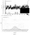
セクションA2.2で説明した行ウィンドウイングヒューリスティックの影響を評価するために、シミュレータを実装した。フレームiの内容に基づいて、フレームi+1の行ウィンドウイング構成を予測しようとする。定性的な評価のために、それはリアルタイムで行ウィンドウと追跡されたブロブをグラフィカルに表示し、さらに注意が必要なイベントのスクリーンショットを保存する(読み出し率の変化、すなわち読み出されるフレームの部分、または見えないブロブ)。最後に、読み出し率曲線、ヒストグラム、および失われたブロブを示す自動HTMLレポートを出力する。図9はシミュレータのスクリーンショットを示している。つまり、白いディスクが追跡されたブロブで、赤い/クリアの領域または線が行ウィンドウで、黒い/暗い領域がフレームの見えない部分である、実行中のシミュレータである。図10は、生成されたレポートの例を示している。A2.3. Results A simulator was implemented to evaluate the impact of the row windowing heuristic described in Section A2.2. Based on the contents of frame i, we try to predict the row windowing configuration for frame i+1. For qualitative evaluation, it graphically displays line windows and tracked blobs in real-time, and additionally saves screenshots of events requiring attention (changes in readout rate, i.e. parts of the frame readout, or invisible blob). Finally, it outputs an automated HTML report showing readout rate curves, histograms, and missing blobs. FIG. 9 shows a screenshot of the simulator. That is, the running simulator where the white disc is the tracked blob, the red/clear area or line is the line window, and the black/dark area is the invisible part of the frame. FIG. 10 shows an example of a generated report.
結論として、我々は、環境が制御されているならば、行ウィンドウ光学追跡のための我々のヒューリスティックが価値があることを示した。環境リスクを克服するために、行ウィンドウイング予測装置に加えて読み出し時間モニタ機構を取得パイプラインに追加する必要がある。これにより、エンドユーザは、アプリケーション固有の時間的制約に応じて、期限切れのデータの決定に基づいているかどうかを検出できる。 In conclusion, we have shown that our heuristics for line-window optical tracking are valuable if the environment is controlled. To overcome environmental risks, a readout time monitor mechanism should be added to the acquisition pipeline in addition to the row windowing predictor. This allows the end-user to detect whether or not to base the determination of expired data on application-specific time constraints.
図10は、シミュレータのHTML出力を示している。一番上のグラフは、キャプチャ中の読み出し率の曲線を示している。ユーザは自分のマウスを使ってスクリーンショットを見るためにイベントを問い合わせることができる。下のグラフは、読み出し率の分布を評価するためのヒストグラムである。 Figure 10 shows the HTML output of the simulator. The top graph shows the readout rate curve during capture. Users can use their mouse to query events to view screenshots. The lower graph is a histogram for evaluating the read rate distribution.
附属書2:圧縮部分画像中の基準重心を検索するためのアルゴリズムの例
(図1に示されるような)委任処理では、画像データは完全にコンピュータ上で処理される。これは、ムーアの法則に準拠しているため、最新のプロセッサでは制限されない。唯一の欠点は、追跡システムからコンピュータへのデータの送信である。ギガビットイーサネット(登録商標)接続(現在はどのPCでも利用可能である)と、8ビットのピクセル深度を有する2台のフルHDグレースケールカメラで構成されるシステムを検討すると、理論上の最大更新速度は次のようになる。
1024^3/(8*2*1920*1080)=32HzAnnex 2: Examples of Algorithms for Finding Reference Centroids in Compressed Sub-Images In delegated processing (as shown in FIG. 1) the image data are processed entirely on the computer. It complies with Moore's Law and is not limited by modern processors. The only drawback is the transmission of data from the tracking system to the computer. Considering a system consisting of a Gigabit Ethernet connection (available today on any PC) and two Full HD grayscale cameras with 8-bit pixel depth, the maximum theoretical update rate is becomes
1024^3/(8*2*1920*1080) = 32Hz
更新速度を向上させるための良い方法は、追跡システムで画像を圧縮し、コンピュータでそれらを解凍することである。残念ながら、このアプローチでは、画像をさらに処理する前にまず解凍する必要があるため、コンピュータ上ではるかに多くのデータ処理手段が必要になる。 A good way to improve update speed is to compress the images in the tracking system and decompress them in the computer. Unfortunately, this approach requires much more data processing means on the computer, as the image must first be decompressed before it can be further processed.
現代の光学追跡は正確さとスピードを要求する。高解像度のカメラを使用することで精度が達成され、実際の動きとそれに対応するアプリケーションでの測定との間の待ち時間を短縮するには速い更新速度が必要である。 Modern optical tracking demands accuracy and speed. Accuracy is achieved through the use of high-resolution cameras, and fast update rates are required to reduce latency between actual motion and measurements in corresponding applications.
一例として、光学追跡によって駆動されるロボットシステムの速度は、追跡システムの更新速度および待ち時間に直接関係している。 As an example, the speed of a robotic system driven by optical tracking is directly related to the update rate and latency of the tracking system.
我々は、解凍を必要とせずに処理ユニット(例えばPC)によって直接使用されることができる圧縮表現を提供することによって、コンピュータ上の解凍オーバーヘッドの欠点を解決することを提案する。
・このアプローチの第1の利点は、更新速度が圧縮効率によって制限されることである(伝送が処理チェーン内の最も弱いリンクであるため)。
・本発明の別の利点は、圧縮画像をプロセッサのキャッシュにより効率的に格納することができるので、それはより高速に処理されることである。We propose to solve the drawback of decompression overhead on computers by providing a compressed representation that can be used directly by a processing unit (eg, PC) without the need for decompression.
• The first advantage of this approach is that the update rate is limited by the compression efficiency (because transmission is the weakest link in the processing chain).
• Another advantage of the present invention is that the compressed image can be stored more efficiently in the processor's cache, so it is processed faster.
実際には、我々が開発した我々の圧縮を使うと、我々は典型的な構成でファクター10で改善された最大更新速度を得る(図A1.2参照)。この圧縮アルゴリズムはフル8ビット画像を圧縮することだけができる。それは以下の通りである。 In fact, with our compression that we have developed, we get a maximum update rate improvement of a factor of 10 with typical configurations (see Figure A1.2). This compression algorithm can only compress full 8-bit images. It is as follows.
圧縮アルゴリズムは以下の出力を生成する。
・出力データは8ビットで構成され、MSBは白と黒のピクセルを区別する。
○1は7つのLSBが元のピクセル強度を2で割ったものであることを意味する。
○7つのLSBが連続する黒ピクセルの数であることを意味する。以下の例外がある。
・0x80は128個の連続した黒の値を意味する。
・2バイトでエンコードされた値が続く0x00(リトルエンディアン、すなわちLSBが最初)は、いくつかの完全に黒い線を示す。この0x00バイトのアドレスは16の倍数でなければならない。
・他の0x00は無視される(これは、16バイトの倍数を書き込まなければならないFPGAで使用されるノーオペレーション文字である)。The compression algorithm produces the following output.
• The output data consists of 8 bits, with the MSB distinguishing between white and black pixels.
o 1 means the 7 LSBs are the original pixel intensity divided by 2.
o Meaning that 7 LSBs are the number of consecutive black pixels. There are the following exceptions.
• 0x80 means 128 consecutive black values.
• 0x00 (little endian, ie LSB first) followed by a value encoded in 2 bytes indicates some completely black lines. This 0x00 byte address must be a multiple of 16.
• Other 0x00s are ignored (this is a no-op character used in FPGAs that must write multiples of 16 bytes).
そのような圧縮の利点は、(解凍を必要とせずに)圧縮画像内でブロブの(x、y)位置を直接取得することが容易であることである。 An advantage of such compression is that it is easy to directly obtain the (x,y) position of the blob within the compressed image (without requiring decompression).
この表現は、ラインスキャンフィルアルゴリズムの適合バージョンを使用することによって圧縮画像からブロブを効率的に抽出することを可能にする。スキャンフィルアルゴリズム(https://en.wikipedia.org/wiki/Food_fill#Scanline_Fill)は、フラッドフィルアルゴリズムの最適化であり、潜在的な将来の各ピクセル座標をスタックにプッシュするのではなく、隣接する行(前の行と次の行)を検査、将来のパスに埋められる可能性がある隣接セグメントを見つけ、線分の座標(始点または終点)がスタックにプッシュされる。ほとんどの場合、このスキャンラインアルゴリズムは、ピクセルごとのアルゴリズムよりも少なくとも1桁速い。 This representation allows efficient extraction of blobs from compressed images by using an adapted version of the line scan fill algorithm. The scan-fill algorithm (https://en.wikipedia.org/wiki/Food_fill#Scanline_Fill) is an optimization of the flood-fill algorithm, where instead of pushing each potential future pixel coordinate onto a stack The line (previous and next line) is inspected, adjacent segments are found that may be filled in future paths, and the line segment coordinates (start or end) are pushed onto the stack. In most cases, this scanline algorithm is at least an order of magnitude faster than the pixel-by-pixel algorithm.
説明した構成は、非圧縮バージョンよりも10倍以上高い335Hzの速度で実行できる。 The described arrangement can run at a speed of 335 Hz, which is more than ten times higher than the uncompressed version.
要素のインデックス
10:光学追跡システム
11:カメラ
12:IR LEDのリング
13:内部CPUリソース
20:被追跡ツール
21:マーカ
22:基準
30:PCシステム
31:(タッチ)スクリーン
32:PCとの有線接続
33:スクリーンとPCの接続
34:埋め込みCPUへの内部接続
40:追跡被験物
50:操作者
51:ロボット
52:ロボットのエンドエフェクタ
53:手術用ツール
54:インテリジェント(ロボット)ツール
60:タブレット
61:光学追跡システムへの無線接続
70:該当なし
80:該当なし
90:該当なし
100:カメラセンサ
105:メモリへのピクセル読み出し
106:画像圧縮装置への部分画像読み出し
107:画像圧縮装置
108:圧縮画像のメモリへの転送
110:メモリ
120:データ処理
121:画像セグメンテーションモジュール
122:ブロブ検出モジュール
123:ブロブ識別モジュール
124:三角測量モジュール
125:ジオメトリマッチングモジュール
126:姿勢計算モジュール
127:姿勢データのアプリケーションへの転送
130:エンドユーザアプリケーション
140:圧縮部分画像処理
141:部分圧縮画像を用いた画像セグメンテーションモジュール
142:ブロブ検出モジュール
143:ブロブ識別モジュール
144:三角測量モジュール
145:ジオメトリマッチングモジュール
146:姿勢計算モジュール
147:姿勢データのアプリケーションへの転送Element Index 10: Optical Tracking System 11: Camera 12: Ring of IR LEDs 13: Internal CPU Resources 20: Tracked Tool 21: Marker 22: Reference 30: PC System 31: (Touch) Screen 32: Wired Connection to PC 33: Screen to PC Connection 34: Internal Connection to Embedded CPU 40: Tracked Subject 50: Operator 51: Robot 52: Robotic End Effector 53: Surgical Tool 54: Intelligent (robotic) Tool 60: Tablet 61: Wireless connection to optical tracking system 70: N/A 80: N/A 90: N/A 100: Camera sensor 105: Pixel readout to memory 106: Partial image readout to image compressor 107: Image compressor 108: Compressed image Transfer to Memory 110: Memory 120: Data Processing 121: Image Segmentation Module 122: Blob Detection Module 123: Blob Identification Module 124: Triangulation Module 125: Geometry Matching Module 126: Pose Calculation Module 127: Transfer of Pose Data to Application 130: End-user application 140: Compressed sub-image processing 141: Image segmentation module using sub-compressed images
142: Blob Detection Module 143: Blob Identification Module 144: Triangulation Module 145: Geometry Matching Module 146: Pose Calculation Module 147: Transfer of Pose Data to Applications
Claims (12)
Translated fromJapanese-)オブジェクト(20)および/または人(40)上に配置されたマーカ(21)に取り付けられた少なくとも1つの基準(22)と、
-)センサデータを介して前記基準(22)を検出する光学センサ(11)を有する光学追跡システム(10)と、
-)手段であって、
検出ヒューリスティックに基づいて複数のウィンドウであって前記光学センサ(11)内での前記基準(22)の推定される位置に対応する複数のウィンドウを識別し、
識別した複数の前記ウィンドウに基づいて前記センサデータの一部を抽出する、
ように構成され、前記センサデータのうち抽出された部分が部分画像に対応する、手段と、
-)前記センサデータの一部を圧縮するための少なくとも1つの圧縮モジュール(107)と、
-)前記センサ(11)によって検出された前記マーカ(21)の位置および/または配向を前記圧縮モジュール(107)からの圧縮した前記センサデータの一部の処置によって決定するための少なくともメモリ(110)およびセンサデータ処理手段(140~146)を含む電子的手段と、
-)前記マーカの前記決定された位置および/または配向をさらなる処理のためにアプリケーション(130)に転送するための通信手段と、
を含む、装置。An apparatus for high speed tracking of optical fiducials and markers, comprising:
-) at least one fiducial (22) attached to a marker (21) placed on the object (20) and/or the person (40);
-) an optical tracking system (10) having an optical sensor (11) that detects said fiducial (22) via sensor data;
-) means,
identifying a plurality of windows based on detection heuristics, the plurality of windows corresponding to the estimated position of the fiducial (22) within the optical sensor (11);
extracting a portion of the sensor data based on the identified plurality of windows;
means, wherein the extracted portion of the sensor data corresponds to a partial image;
-) at least one compression module (107) for compressing a portion of said sensor data;
-) at least a memory (110) for determining the position and/or orientation of said marker (21) detected by said sensor (11) by processing a portion of said compressed sensor data from said compression module (107); ) and sensor data processing means (140-146);
-) communication means for forwarding said determined position and/or orientation of said marker to an application (130) for further processing;
apparatus, including
Applications Claiming Priority (3)
| Application Number | Priority Date | Filing Date | Title |
|---|---|---|---|
| US201762458697P | 2017-02-14 | 2017-02-14 | |
| US62/458,697 | 2017-02-14 | ||
| PCT/IB2018/050899WO2018150336A1 (en) | 2017-02-14 | 2018-02-14 | High-speed optical tracking with compression and/or cmos windowing |
Publications (3)
| Publication Number | Publication Date |
|---|---|
| JP2020507436A JP2020507436A (en) | 2020-03-12 |
| JP2020507436A5 JP2020507436A5 (en) | 2021-03-25 |
| JP7304820B2true JP7304820B2 (en) | 2023-07-07 |
Family
ID=61691536
Family Applications (1)
| Application Number | Title | Priority Date | Filing Date |
|---|---|---|---|
| JP2019565080AActiveJP7304820B2 (en) | 2017-02-14 | 2018-02-14 | Fast optical tracking with compression and/or CMOS windowing |
Country Status (6)
| Country | Link |
|---|---|
| US (4) | US11013562B2 (en) |
| EP (1) | EP3582711A1 (en) |
| JP (1) | JP7304820B2 (en) |
| CN (1) | CN110461270B (en) |
| AU (1) | AU2018220946B2 (en) |
| WO (1) | WO2018150336A1 (en) |
Families Citing this family (26)
| Publication number | Priority date | Publication date | Assignee | Title |
|---|---|---|---|---|
| GB2536650A (en) | 2015-03-24 | 2016-09-28 | Augmedics Ltd | Method and system for combining video-based and optic-based augmented reality in a near eye display |
| US20230355317A1 (en)* | 2015-11-16 | 2023-11-09 | Think Surgical, Inc. | Method for confirming registration of tracked bones |
| AU2016357286B2 (en)* | 2015-11-16 | 2021-10-14 | Think Surgical, Inc. | Method for confirming registration of tracked bones |
| US11980507B2 (en) | 2018-05-02 | 2024-05-14 | Augmedics Ltd. | Registration of a fiducial marker for an augmented reality system |
| DE102019004233B4 (en) | 2018-06-15 | 2022-09-22 | Mako Surgical Corp. | SYSTEMS AND METHODS FOR TRACKING OBJECTS |
| EP3639787A1 (en)* | 2018-10-15 | 2020-04-22 | Dental Design | Method for designing a prosthetic element and system for assisting an operator in a dental restoration |
| US11766296B2 (en) | 2018-11-26 | 2023-09-26 | Augmedics Ltd. | Tracking system for image-guided surgery |
| US20220151706A1 (en)* | 2019-03-21 | 2022-05-19 | Petal Surgical, Inc. | Enhanced reality medical guidance systems and methods of use |
| AU2020303722A1 (en)* | 2019-06-28 | 2022-01-27 | Mako Surgical Corp. | Tracker-based surgical navigation |
| US12178666B2 (en) | 2019-07-29 | 2024-12-31 | Augmedics Ltd. | Fiducial marker |
| US11980506B2 (en) | 2019-07-29 | 2024-05-14 | Augmedics Ltd. | Fiducial marker |
| US11382712B2 (en) | 2019-12-22 | 2022-07-12 | Augmedics Ltd. | Mirroring in image guided surgery |
| US11095870B1 (en)* | 2020-04-23 | 2021-08-17 | Sony Corporation | Calibration of cameras on unmanned aerial vehicles using human joints |
| KR20230034296A (en)* | 2020-06-11 | 2023-03-09 | 모노그램 올소패딕스 인크. | Navigation and/or robot tracking methods and systems |
| US11389252B2 (en) | 2020-06-15 | 2022-07-19 | Augmedics Ltd. | Rotating marker for image guided surgery |
| US20240233935A1 (en)* | 2020-07-13 | 2024-07-11 | Front Line Medical Technologies Inc. | Devices and Method for Blood Vessel Occlusion |
| US12239385B2 (en) | 2020-09-09 | 2025-03-04 | Augmedics Ltd. | Universal tool adapter |
| WO2022094651A1 (en)* | 2020-11-03 | 2022-05-12 | Kico Knee Innovation Company Pty Limited | Scanner for intraoperative application |
| US11896445B2 (en) | 2021-07-07 | 2024-02-13 | Augmedics Ltd. | Iliac pin and adapter |
| US12150821B2 (en) | 2021-07-29 | 2024-11-26 | Augmedics Ltd. | Rotating marker and adapter for image-guided surgery |
| WO2023021448A1 (en) | 2021-08-18 | 2023-02-23 | Augmedics Ltd. | Augmented-reality surgical system using depth sensing |
| EP4511809A1 (en) | 2022-04-21 | 2025-02-26 | Augmedics Ltd. | Systems and methods for medical image visualization |
| CN115721417B (en)* | 2022-09-09 | 2024-01-30 | 苏州铸正机器人有限公司 | A device and method for measuring the full field of view of the end position of a surgical robot |
| IL319523A (en) | 2022-09-13 | 2025-05-01 | Augmedics Ltd | Augmented reality eyewear for image-guided medical intervention |
| KR20250062198A (en) | 2023-10-30 | 2025-05-08 | 주식회사 디지트랙 | Position tracking device and method of automatic lens exchange type |
| US12330318B1 (en) | 2024-12-11 | 2025-06-17 | Digital Dental Design Robotics | Dynamic real-time tracking and robotic systems |
Citations (4)
| Publication number | Priority date | Publication date | Assignee | Title |
|---|---|---|---|---|
| JP2005509449A (en) | 2001-03-26 | 2005-04-14 | エルビー メディカル ゲーエムベーハー | Material excision or material processing method and device system |
| JP2008011913A (en) | 2006-07-03 | 2008-01-24 | Olympus Medical Systems Corp | Capsule medical device and capsule medical device system |
| WO2011021192A1 (en) | 2009-08-17 | 2011-02-24 | Mazor Surgical Technologies Ltd. | Device for improving the accuracy of manual operations |
| WO2016139638A1 (en) | 2015-03-05 | 2016-09-09 | Atracsys Sàrl | Redundant reciprocal tracking system |
Family Cites Families (49)
| Publication number | Priority date | Publication date | Assignee | Title |
|---|---|---|---|---|
| US6167295A (en)* | 1991-01-28 | 2000-12-26 | Radionics, Inc. | Optical and computer graphic stereotactic localizer |
| US5603318A (en)* | 1992-04-21 | 1997-02-18 | University Of Utah Research Foundation | Apparatus and method for photogrammetric surgical localization |
| US6980690B1 (en)* | 2000-01-20 | 2005-12-27 | Canon Kabushiki Kaisha | Image processing apparatus |
| US20010056477A1 (en)* | 2000-02-15 | 2001-12-27 | Mcternan Brennan J. | Method and system for distributing captured motion data over a network |
| US7464877B2 (en)* | 2003-11-13 | 2008-12-16 | Metrologic Instruments, Inc. | Digital imaging-based bar code symbol reading system employing image cropping pattern generator and automatic cropped image processor |
| US6909808B2 (en)* | 2002-03-08 | 2005-06-21 | Anzus, Inc. | Image compression to enhance optical correlation |
| NZ518092A (en)* | 2002-03-28 | 2004-11-26 | Pulse Data Internat Ltd | Low vision video magnifier viewing apparatus having digital zoom feature |
| US20110015521A1 (en)* | 2003-03-27 | 2011-01-20 | Boulder Innovation Group, Inc. | Means of Tracking Movement of Bodies During Medical Treatment |
| WO2005086062A2 (en)* | 2004-03-05 | 2005-09-15 | Depuy International Limited | Registration methods and apparatus |
| CA2563478A1 (en)* | 2004-04-16 | 2005-10-27 | James A. Aman | Automatic event videoing, tracking and content generation system |
| US7770799B2 (en)* | 2005-06-03 | 2010-08-10 | Hand Held Products, Inc. | Optical reader having reduced specular reflection read failures |
| US7933448B2 (en)* | 2005-06-13 | 2011-04-26 | Shuffle Master, Inc. | Card reading system employing CMOS reader |
| DE102006037599B4 (en)* | 2006-08-09 | 2019-08-14 | Carl Zeiss Ag | Observation system with image recording function |
| WO2008128205A1 (en)* | 2007-04-13 | 2008-10-23 | Presler Ari M | Digital cinema camera system for recording, editing and visualizing images |
| CN100576908C (en)* | 2007-11-30 | 2009-12-30 | 汤一平 | Stereo intelligent camera apparatus based on omnibearing vision sensor |
| EP3272395B1 (en)* | 2007-12-23 | 2019-07-17 | Carl Zeiss Meditec, Inc. | Devices for detecting, controlling, and predicting radiation delivery |
| EP2189943B1 (en)* | 2008-11-19 | 2014-09-24 | Brainlab AG | Detection of vitally moved regions in an analysis image |
| US9060714B2 (en)* | 2008-12-04 | 2015-06-23 | The Regents Of The University Of California | System for detection of body motion |
| EP2254091B1 (en)* | 2009-05-19 | 2020-03-25 | Veoneer Sweden AB | Vision system and method for a motor vehicle |
| US9019349B2 (en)* | 2009-07-31 | 2015-04-28 | Naturalpoint, Inc. | Automated collective camera calibration for motion capture |
| US20110098553A1 (en)* | 2009-10-28 | 2011-04-28 | Steven Robbins | Automatic registration of images for image guided surgery |
| CN101975935B (en)* | 2010-09-03 | 2012-12-05 | 杭州电子科技大学 | Partial echo compressed sensing-based quick magnetic resonance imaging method |
| EP2468207A1 (en)* | 2010-12-21 | 2012-06-27 | Renishaw (Ireland) Limited | Method and apparatus for analysing images |
| CN102186025B (en)* | 2011-03-09 | 2012-10-03 | 天津大学 | CMOS Imaging Measurement Value Acquisition System and Method Based on Compressed Sensing |
| US8791901B2 (en)* | 2011-04-12 | 2014-07-29 | Sony Computer Entertainment, Inc. | Object tracking with projected reference patterns |
| EP2557391A1 (en)* | 2011-08-12 | 2013-02-13 | Leica Geosystems AG | Measuring device for determining the spatial location of a measuring aid |
| CN104081414B (en)* | 2011-09-28 | 2017-08-01 | Fotonation开曼有限公司 | Systems and methods for encoding and decoding light field image files |
| EP2816966B1 (en)* | 2012-02-22 | 2023-10-25 | Veran Medical Technologies, Inc. | Steerable surgical catheter comprising a biopsy device at the distal end portion thereof |
| EP2863827B1 (en)* | 2012-06-21 | 2022-11-16 | Globus Medical, Inc. | Surgical robot platform |
| EP2953569B1 (en)* | 2013-02-11 | 2022-08-17 | Neomedz Sàrl | Tracking apparatus for tracking an object with respect to a body |
| BR112014028811B1 (en)* | 2013-03-19 | 2020-11-17 | Koninklijke Philips N.V. | imaging system, method for registering an image of an object in a spectral band of terahertz radiation through radiography and visualization of the image in visible light, and storage medium |
| JP6434513B2 (en)* | 2013-08-12 | 2018-12-05 | アップル インコーポレイテッドApple Inc. | Inertial navigation based on vision |
| US20160199148A1 (en)* | 2013-08-30 | 2016-07-14 | The Board Of Regents Of The University Of Texas System | Endo-navigation systems and methods for surgical procedures and cpr |
| CN103686006B (en)* | 2013-12-24 | 2017-04-05 | 北京交通大学 | A kind of global formula exposure cmos image sensor based on compression sensing |
| CN103886585A (en)* | 2014-02-18 | 2014-06-25 | 浙江大学 | Video tracking method based on rank learning |
| CN103905733B (en)* | 2014-04-02 | 2018-01-23 | 哈尔滨工业大学深圳研究生院 | A kind of method and system of monocular cam to real time face tracking |
| KR20150116260A (en)* | 2014-04-07 | 2015-10-15 | 삼성전자주식회사 | Method for marker tracking and an electronic device thereof |
| US20170333136A1 (en)* | 2014-10-29 | 2017-11-23 | Intellijoint Surgical Inc. | Systems and devices including a surgical navigation camera with a kinematic mount and a surgical drape with a kinematic mount adapter |
| CN104680554B (en)* | 2015-01-08 | 2017-10-31 | 深圳大学 | Compression tracking and system based on SURF |
| US10499996B2 (en)* | 2015-03-26 | 2019-12-10 | Universidade De Coimbra | Methods and systems for computer-aided surgery using intra-operative video acquired by a free moving camera |
| CN104715494A (en)* | 2015-03-30 | 2015-06-17 | 江南大学 | Video target compressing and tracking method based on partial sensitive histogram |
| US10043551B2 (en)* | 2015-06-25 | 2018-08-07 | Intel Corporation | Techniques to save or delete a video clip |
| CN105072359B (en)* | 2015-08-26 | 2018-09-25 | 中国科学院上海高等研究院 | Cmos image sensor imaging system based on compressed sensing and method |
| US20170086941A1 (en) | 2015-09-25 | 2017-03-30 | Atracsys | Marker for Optical Tracking System |
| US10095928B2 (en)* | 2015-12-22 | 2018-10-09 | WorldViz, Inc. | Methods and systems for marker identification |
| US20210030479A1 (en) | 2016-06-02 | 2021-02-04 | Atracsys Sàrl | Mobile surgical navigation system |
| US20200129240A1 (en)* | 2017-06-30 | 2020-04-30 | Mirus Llc | Systems and methods for intraoperative planning and placement of implants |
| US10348404B1 (en)* | 2018-05-09 | 2019-07-09 | Ford Global Technologies, Llc | Visible light communication system with pixel alignment for high data rate |
| CN117351277A (en)* | 2023-10-09 | 2024-01-05 | 南京理工大学 | A target recognition method based on compressed reconstruction-free model |
- 2018
- 2018-02-14EPEP18712008.4Apatent/EP3582711A1/enactivePending
- 2018-02-14JPJP2019565080Apatent/JP7304820B2/enactiveActive
- 2018-02-14USUS16/485,903patent/US11013562B2/enactiveActive
- 2018-02-14WOPCT/IB2018/050899patent/WO2018150336A1/ennot_activeCeased
- 2018-02-14AUAU2018220946Apatent/AU2018220946B2/enactiveActive
- 2018-02-14CNCN201880011843.8Apatent/CN110461270B/enactiveActive
- 2020
- 2020-04-22USUS16/855,114patent/US11350997B2/enactiveActive
- 2022
- 2022-01-28USUS17/587,326patent/US11826110B2/enactiveActive
- 2023
- 2023-10-31USUS18/498,466patent/US12310679B2/enactiveActive
Patent Citations (4)
| Publication number | Priority date | Publication date | Assignee | Title |
|---|---|---|---|---|
| JP2005509449A (en) | 2001-03-26 | 2005-04-14 | エルビー メディカル ゲーエムベーハー | Material excision or material processing method and device system |
| JP2008011913A (en) | 2006-07-03 | 2008-01-24 | Olympus Medical Systems Corp | Capsule medical device and capsule medical device system |
| WO2011021192A1 (en) | 2009-08-17 | 2011-02-24 | Mazor Surgical Technologies Ltd. | Device for improving the accuracy of manual operations |
| WO2016139638A1 (en) | 2015-03-05 | 2016-09-09 | Atracsys Sàrl | Redundant reciprocal tracking system |
Also Published As
| Publication number | Publication date |
|---|---|
| US20240058076A1 (en) | 2024-02-22 |
| US11826110B2 (en) | 2023-11-28 |
| JP2020507436A (en) | 2020-03-12 |
| CN110461270A (en) | 2019-11-15 |
| US11350997B2 (en) | 2022-06-07 |
| AU2018220946A1 (en) | 2019-09-05 |
| US11013562B2 (en) | 2021-05-25 |
| EP3582711A1 (en) | 2019-12-25 |
| US20200345428A1 (en) | 2020-11-05 |
| CN110461270B (en) | 2023-01-10 |
| WO2018150336A1 (en) | 2018-08-23 |
| US20200008881A1 (en) | 2020-01-09 |
| AU2018220946B2 (en) | 2023-12-14 |
| US20220151710A1 (en) | 2022-05-19 |
| US12310679B2 (en) | 2025-05-27 |
Similar Documents
| Publication | Publication Date | Title |
|---|---|---|
| JP7304820B2 (en) | Fast optical tracking with compression and/or CMOS windowing | |
| US10937179B2 (en) | System and method for 3D scene reconstruction with dual complementary pattern illumination | |
| US11877843B2 (en) | Human body measurement using thermographic images | |
| CN106535812B (en) | Surgical system with haptic feedback based on quantitative three-dimensional imaging | |
| US10492873B2 (en) | Medical spatial orientation system | |
| US7561733B2 (en) | Patient registration with video image assistance | |
| EP3076892B1 (en) | A medical optical tracking system | |
| CN108257177B (en) | Positioning system and method based on spatial identification | |
| KR102508831B1 (en) | Remote image transmission system, display apparatus and guide displaying method of thereof | |
| CN117836819A (en) | Method and system for generating a training data set for keypoint detection and method and system for predicting the 3D position of a virtual marker on an unmarked object | |
| TWI769370B (en) | Focus detection apparatus and method thereof | |
| US12262868B2 (en) | Systems and methods for performance of depth sensor and auxiliary sensor-based operations associated with a computer-assisted surgical system | |
| US20240374319A1 (en) | Systems and methods for tracking locations of interest in endoscopic imaging | |
| Wu et al. | Shape-from-shading under near point lighting and partial views for orthopedic endoscopy | |
| WO2024095134A1 (en) | Registration and navigation in cranial procedures | |
| TW201915442A (en) | Method and system for tracking object | |
| CN118570345A (en) | Virtual object driving system, method, storage medium and electronic device |
Legal Events
| Date | Code | Title | Description |
|---|---|---|---|
| RD03 | Notification of appointment of power of attorney | Free format text:JAPANESE INTERMEDIATE CODE: A7423 Effective date:20190919 | |
| RD04 | Notification of resignation of power of attorney | Free format text:JAPANESE INTERMEDIATE CODE: A7424 Effective date:20190925 | |
| A521 | Request for written amendment filed | Free format text:JAPANESE INTERMEDIATE CODE: A523 Effective date:20210212 | |
| A621 | Written request for application examination | Free format text:JAPANESE INTERMEDIATE CODE: A621 Effective date:20210212 | |
| A977 | Report on retrieval | Free format text:JAPANESE INTERMEDIATE CODE: A971007 Effective date:20211126 | |
| A131 | Notification of reasons for refusal | Free format text:JAPANESE INTERMEDIATE CODE: A131 Effective date:20211206 | |
| A521 | Request for written amendment filed | Free format text:JAPANESE INTERMEDIATE CODE: A523 Effective date:20220307 | |
| A131 | Notification of reasons for refusal | Free format text:JAPANESE INTERMEDIATE CODE: A131 Effective date:20220725 | |
| A601 | Written request for extension of time | Free format text:JAPANESE INTERMEDIATE CODE: A601 Effective date:20221025 | |
| A521 | Request for written amendment filed | Free format text:JAPANESE INTERMEDIATE CODE: A523 Effective date:20221221 | |
| A02 | Decision of refusal | Free format text:JAPANESE INTERMEDIATE CODE: A02 Effective date:20230116 | |
| A521 | Request for written amendment filed | Free format text:JAPANESE INTERMEDIATE CODE: A523 Effective date:20230512 | |
| A911 | Transfer to examiner for re-examination before appeal (zenchi) | Free format text:JAPANESE INTERMEDIATE CODE: A911 Effective date:20230519 | |
| TRDD | Decision of grant or rejection written | ||
| A01 | Written decision to grant a patent or to grant a registration (utility model) | Free format text:JAPANESE INTERMEDIATE CODE: A01 Effective date:20230605 | |
| A61 | First payment of annual fees (during grant procedure) | Free format text:JAPANESE INTERMEDIATE CODE: A61 Effective date:20230627 | |
| R150 | Certificate of patent or registration of utility model | Ref document number:7304820 Country of ref document:JP Free format text:JAPANESE INTERMEDIATE CODE: R150 |