JP7302599B2 - Defect discrimination method, defect discrimination device, defect discrimination program and recording medium - Google Patents
Defect discrimination method, defect discrimination device, defect discrimination program and recording mediumDownload PDFInfo
- Publication number
- JP7302599B2 JP7302599B2JP2020525777AJP2020525777AJP7302599B2JP 7302599 B2JP7302599 B2JP 7302599B2JP 2020525777 AJP2020525777 AJP 2020525777AJP 2020525777 AJP2020525777 AJP 2020525777AJP 7302599 B2JP7302599 B2JP 7302599B2
- Authority
- JP
- Japan
- Prior art keywords
- defect
- correction
- unit
- value
- defect candidate
- Prior art date
- Legal status (The legal status is an assumption and is not a legal conclusion. Google has not performed a legal analysis and makes no representation as to the accuracy of the status listed.)
- Active
Links
Images


Classifications
- G—PHYSICS
- G06—COMPUTING OR CALCULATING; COUNTING
- G06T—IMAGE DATA PROCESSING OR GENERATION, IN GENERAL
- G06T7/00—Image analysis
- G06T7/0002—Inspection of images, e.g. flaw detection
- G06T7/0004—Industrial image inspection
- G—PHYSICS
- G01—MEASURING; TESTING
- G01N—INVESTIGATING OR ANALYSING MATERIALS BY DETERMINING THEIR CHEMICAL OR PHYSICAL PROPERTIES
- G01N21/00—Investigating or analysing materials by the use of optical means, i.e. using sub-millimetre waves, infrared, visible or ultraviolet light
- G01N21/84—Systems specially adapted for particular applications
- G01N21/88—Investigating the presence of flaws or contamination
- G01N21/8806—Specially adapted optical and illumination features
- G—PHYSICS
- G01—MEASURING; TESTING
- G01N—INVESTIGATING OR ANALYSING MATERIALS BY DETERMINING THEIR CHEMICAL OR PHYSICAL PROPERTIES
- G01N21/00—Investigating or analysing materials by the use of optical means, i.e. using sub-millimetre waves, infrared, visible or ultraviolet light
- G01N21/84—Systems specially adapted for particular applications
- G01N21/88—Investigating the presence of flaws or contamination
- G01N21/8851—Scan or image signal processing specially adapted therefor, e.g. for scan signal adjustment, for detecting different kinds of defects, for compensating for structures, markings, edges
- G—PHYSICS
- G01—MEASURING; TESTING
- G01N—INVESTIGATING OR ANALYSING MATERIALS BY DETERMINING THEIR CHEMICAL OR PHYSICAL PROPERTIES
- G01N21/00—Investigating or analysing materials by the use of optical means, i.e. using sub-millimetre waves, infrared, visible or ultraviolet light
- G01N21/84—Systems specially adapted for particular applications
- G01N21/88—Investigating the presence of flaws or contamination
- G01N21/8806—Specially adapted optical and illumination features
- G01N2021/8829—Shadow projection or structured background, e.g. for deflectometry
- G—PHYSICS
- G01—MEASURING; TESTING
- G01N—INVESTIGATING OR ANALYSING MATERIALS BY DETERMINING THEIR CHEMICAL OR PHYSICAL PROPERTIES
- G01N21/00—Investigating or analysing materials by the use of optical means, i.e. using sub-millimetre waves, infrared, visible or ultraviolet light
- G01N21/84—Systems specially adapted for particular applications
- G01N21/88—Investigating the presence of flaws or contamination
- G01N21/8851—Scan or image signal processing specially adapted therefor, e.g. for scan signal adjustment, for detecting different kinds of defects, for compensating for structures, markings, edges
- G01N2021/8854—Grading and classifying of flaws
- G01N2021/8867—Grading and classifying of flaws using sequentially two or more inspection runs, e.g. coarse and fine, or detecting then analysing
- G—PHYSICS
- G06—COMPUTING OR CALCULATING; COUNTING
- G06T—IMAGE DATA PROCESSING OR GENERATION, IN GENERAL
- G06T2207/00—Indexing scheme for image analysis or image enhancement
- G06T2207/30—Subject of image; Context of image processing
- G06T2207/30108—Industrial image inspection
- G06T2207/30156—Vehicle coating
Landscapes
- Engineering & Computer Science (AREA)
- Physics & Mathematics (AREA)
- General Physics & Mathematics (AREA)
- Life Sciences & Earth Sciences (AREA)
- Analytical Chemistry (AREA)
- Pathology (AREA)
- Immunology (AREA)
- Health & Medical Sciences (AREA)
- General Health & Medical Sciences (AREA)
- Chemical & Material Sciences (AREA)
- Computer Vision & Pattern Recognition (AREA)
- Biochemistry (AREA)
- Quality & Reliability (AREA)
- Signal Processing (AREA)
- Theoretical Computer Science (AREA)
- Investigating Materials By The Use Of Optical Means Adapted For Particular Applications (AREA)
- Length Measuring Devices By Optical Means (AREA)
Description
Translated fromJapanese本発明は、被測定物の表面に発生する欠陥を判別する欠陥判別方法、欠陥判別装置、欠陥判別プログラムおよび欠陥判別プログラムが記録された記録媒体に関する。 The present invention relates to a defect discrimination method, a defect discrimination apparatus, a defect discrimination program, and a recording medium in which the defect discrimination program is recorded.
特開平9-318337号公報に示す表面欠陥判別装置は、門型形状をなす照明手段から明暗パターンを形成する照明を被検査体に照射し、同じく門型形状をなす撮像装置固定手段に取り付けられた複数個の撮像装置で被検査体の被検査面を撮像する。そして、撮像画像を画像処理することで被検査面の輝度レベルを測定して輝度レベルと閾値とを比較することで欠陥検査を行う。 The surface defect discriminating apparatus disclosed in Japanese Patent Application Laid-Open No. 9-318337 irradiates an object to be inspected with illumination that forms a bright and dark pattern from a gate-shaped illumination means, and is attached to an imaging device fixing means that is also gate-shaped. The inspection surface of the object to be inspected is imaged by a plurality of imaging devices. Then, by performing image processing on the captured image, the brightness level of the surface to be inspected is measured, and the brightness level is compared with a threshold value to perform defect inspection.
特開平8-86634号公報に示す表面欠陥検査装置は、明暗パターンを有する照明を被検査体に照射する。撮像手段は、照射された部分を撮像して画像データを取得する。そして画像データを周波数成分ごとに分析して、欠陥の検査を行っている。このように周波数を分けて分析することで、ゆず肌のような極めて薄い凹凸を欠陥と誤検出するのを抑制し、より精密な欠陥検出を行うことが可能である。 A surface defect inspection apparatus disclosed in Japanese Patent Application Laid-Open No. 8-86634 irradiates an object to be inspected with illumination having a bright and dark pattern. The imaging means acquires image data by imaging the irradiated portion. Then, the image data is analyzed for each frequency component to inspect for defects. By dividing and analyzing the frequencies in this way, it is possible to suppress erroneous detection of extremely thin irregularities such as citrus peel as defects, and to perform more precise defect detection.
しかしながら、特開平9-318337号公報に記載の表面欠陥判別装置では、複数の撮像装置が必要であり、装置が大型且つ複雑になる。また、複数の撮像装置で撮像する場合、撮像装置の制御が複雑であるとともに、画像処理に手間と時間がかかる場合がある。このことからも、欠陥検査の作業に多くの手間と時間がかかる虞がある。 However, the surface defect discriminating apparatus disclosed in Japanese Patent Application Laid-Open No. 9-318337 requires a plurality of imaging devices, which makes the device large and complicated. Further, when images are captured by a plurality of image capturing apparatuses, control of the image capturing apparatuses is complicated, and image processing may take time and effort. For this reason as well, there is a risk that the defect inspection work will take a lot of time and effort.
また、特開平8-86634号公報の表面欠陥検査装置のように、明暗パターンを被検査体に照射して、被検査体の表面の欠陥を検出する構成の場合、同じ大きさ及び形状の欠陥であっても、撮像手段の特性上、撮像範囲の中央部分と辺縁部分とでは、画像データにおける欠陥部分の輝度レベルが変動する。そのため、予め決められた閾値で二値化して欠陥を検出すると、撮像画像における欠陥の位置によっては、欠陥ではない表面の凹凸を欠陥と判断してしまう虞がある。すなわち、欠陥の位置によっては、欠陥の誤検出が発生する虞がある。 In addition, as in the surface defect inspection apparatus of Japanese Patent Application Laid-Open No. 8-86634, in the case of a configuration in which a bright and dark pattern is irradiated onto an object to be inspected to detect defects on the surface of the object to be inspected, defects of the same size and shape However, due to the characteristics of the imaging means, the luminance level of the defective portion in the image data varies between the central portion and the peripheral portion of the imaging range. Therefore, if a defect is detected by binarizing with a predetermined threshold value, there is a risk that surface unevenness that is not a defect may be determined as a defect depending on the position of the defect in the captured image. That is, depending on the position of the defect, erroneous detection of the defect may occur.
そこで本発明は、表面の欠陥を精度よく判別することができる欠陥判別方法、欠陥判別装置及び欠陥判別プログラム、ならびに、欠陥判別プログラムを記録した記録媒体を提供することを目的とする。 SUMMARY OF THE INVENTION Accordingly, it is an object of the present invention to provide a defect determination method, a defect determination apparatus, a defect determination program, and a recording medium recording the defect determination program, which are capable of accurately determining surface defects.
上述した目的のうち少なくとも一つを実現するために、本発明の一側面を反映した欠陥判別方法は、明部及び前記明部に比べて輝度が低い暗部が所定のパターンで配列されたパターン照明が照射された被測定物の表面を撮像部で撮像して前記被測定物の表面の欠陥の有無を判別する欠陥判別方法であって、前記被測定物の前記パターン照明が照射されている領域の少なくとも一部を前記撮像部を介して撮像して撮像画像を取得する撮像工程と、前記撮像画像に基づいて欠陥の可能性がある欠陥候補を検出する欠陥候補検出工程と、前記被測定物の表面における欠陥候補が検出された位置の前記撮像部に対する形状の情報である形状情報を取得する形状情報取得工程と、前記欠陥候補の欠陥を判別するための判別値を取得する判別値取得工程と、前記被測定物の表面の前記撮像部に対する形状を形状変数として補正値を備える補正用データベースを参照して前記形状情報に対応する補正値を取得する補正値取得工程と、前記判別値又は閾値のいずれか一方を前記補正値に基づいて補正する補正工程と、補正後の前記判別値と補正していない前記閾値又は補正していない前記判別値と前記補正後の前記閾値とを比較して前記欠陥候補が欠陥であるか否か判別する判別工程とを備える。 In order to achieve at least one of the above objects, a defect determination method reflecting one aspect of the present invention provides pattern illumination in which a bright portion and a dark portion having a lower luminance than the bright portion are arranged in a predetermined pattern. A defect determination method for determining the presence or absence of a defect on the surface of the object to be measured by imaging the surface of the object to be measured irradiated with the pattern illumination, wherein the area of the object to be measured is irradiated with the pattern illumination An imaging step of capturing at least a part of through the imaging unit to acquire a captured image, a defect candidate detecting step of detecting a defect candidate that may be a defect based on the captured image, and the object to be measured A shape information acquisition step of acquiring shape information, which is shape information for the imaging unit at the position where the defect candidate is detected on the surface of the, and a discrimination value acquisition step of acquiring a discrimination value for discriminating the defect of the defect candidate a correction value acquiring step of acquiring a correction value corresponding to the shape information by referring to a correction database having correction values using the shape of the surface of the object to be measured with respect to the imaging unit as a shape variable; a correction step of correcting one of the threshold values based on the correction value; and comparing the corrected discrimination value with the uncorrected threshold value or the uncorrected discrimination value with the corrected threshold value. and a determination step of determining whether the defect candidate is a defect or not.
上記目的を達成するために本発明の欠陥判別方法は、明部及び前記明部に比べて輝度が低い暗部が所定のパターンで配列されたパターン照明が照射された被測定物の表面を撮像部で撮像して前記被測定物の表面の欠陥の有無を判別する欠陥判別方法であって、前記被測定物の前記パターン照明が照射されている領域の少なくとも一部を前記撮像部を介して撮像して撮像画像を取得する撮像工程と、前記撮像画像に基づいて欠陥の可能性がある欠陥候補を検出する欠陥候補検出工程と、前記欠陥候補の前記撮像画像における位置の情報である画像内位置情報を取得する画像内位置取得工程と、前記欠陥候補の欠陥を判別するための判別値を取得する判別値取得工程と、前記撮像画像における位置を画像内位置変数として補正値を備える補正用データベースを参照して前記画像内位置情報に対応する補正値を取得する補正値取得工程と、前記判別値又は閾値のいずれか一方を前記補正用データに基づいて補正する補正工程と、補正後の前記判別値と補正していない前記閾値又は補正していない前記判別値と前記補正後の前記閾値とを比較して前記欠陥候補が欠陥であるか否か判別する判別工程とを備える。 In order to achieve the above object, a defect determination method of the present invention provides a method for detecting a surface of an object to be measured illuminated by pattern illumination in which bright portions and dark portions having lower brightness than the bright portions are arranged in a predetermined pattern. , wherein at least part of a region of the object to be measured irradiated with the pattern illumination is imaged through the imaging unit. a defect candidate detection step of detecting a defect candidate that may be a defect based on the captured image; and an image position that is information on the position of the defect candidate in the captured image. an in-image position acquiring step of acquiring information; a discrimination value acquiring step of acquiring a discriminant value for discriminating the defect of the defect candidate; a correction value acquisition step of acquiring a correction value corresponding to the in-image position information with reference to; a correction step of correcting either the discrimination value or the threshold value based on the correction data; a determination step of determining whether or not the defect candidate is a defect by comparing the determination value with the uncorrected threshold value or the uncorrected determination value with the corrected threshold value.
上記目的を達成するために本発明の欠陥判別方法は、明部及び前記明部に比べて輝度が低い暗部が所定のパターンで配列されたパターン照明が照射された被測定物の表面を撮像部で撮像して前記被測定物の表面の欠陥の有無を判別する欠陥判別方法であって、前記被測定物の前記パターン照明が照射されている領域の少なくとも一部を前記撮像部を介して撮像して撮像画像を取得する撮像工程と、前記撮像画像に基づいて欠陥の可能性がある欠陥候補を検出する欠陥候補検出工程と、前記欠陥候補の前記撮像画像の前記明部又は前記暗部内における位置の情報であるパターン内位置情報を取得するパターン内位置取得工程と、前記欠陥候補の欠陥を判別するための判別値を取得する判別値取得工程と、前記撮像画像における前記明部又は前記暗部内の位置をパターン内位置変数として補正値を備える補正用データベースを参照して前記パターン内位置情報に対応する補正値を取得する補正値取得工程と、前記判別値又は閾値のいずれか一方を前記補正値に基づいて補正する補正工程と、補正後の前記判別値と補正していない前記閾値又は補正していない前記判別値と前記補正後の前記閾値とを比較して前記欠陥候補が欠陥であるか否か判別する判別工程とを備える。 In order to achieve the above object, a defect determination method of the present invention provides a method for detecting a surface of an object to be measured illuminated by pattern illumination in which bright portions and dark portions having lower brightness than the bright portions are arranged in a predetermined pattern. , wherein at least part of a region of the object to be measured irradiated with the pattern illumination is imaged through the imaging unit. a defect candidate detection step of detecting a defect candidate that may be a defect based on the captured image; and a defect candidate in the bright part or the dark part of the captured image of the defect candidate. an in-pattern position acquiring step of acquiring in-pattern position information that is position information; a discrimination value acquiring step of acquiring a discriminant value for discriminating a defect of the defect candidate; and the bright portion or the dark portion in the captured image. a correction value acquiring step of acquiring a correction value corresponding to the in-pattern position information by referring to a correction database having a correction value using the position in the pattern as an in-pattern position variable; a correction step of correcting based on a correction value; and comparing the discriminant value after correction with the uncorrected threshold value or the discriminant value without correction with the threshold value after correction to determine whether the defect candidate is a defect. and a determination step of determining whether or not there is.
上述した目的のうち少なくとも一つを実現するために、本発明の一側面を反映した欠陥判別装置は、明部及び前記明部に比べて輝度が低い暗部が所定のパターンで配列されたパターン照明を被測定物の表面に照射する照明部と、前記被測定物の前記パターン照明が照射されている領域の少なくとも一部を撮像して撮像画像を取得する撮像部と、前記被測定物の表面の前記撮像部に対する形状を形状変数として前記形状変数に関連付けた補正値を備える補正用データベースを記憶する記憶部と、制御処理部とを備え、前記制御処理部は、前記撮像画像に基づいて欠陥の可能性がある欠陥候補を検出する欠陥候補検出部と、前記被測定物の表面における前記欠陥候補が検出された位置の前記撮像部に対する形状の情報である形状情報を取得する形状情報取得部と、前記撮像画像に基づいて前記欠陥を判別するための判別値を取得する判別値取得部と、前記補正用データベースを参照して前記形状情報に対応する補正値を取得する補正値取得部と、前記判別値又は閾値のいずれか一方を前記補正値に基づいて補正する補正部と、補正後の前記判別値と補正していない前記閾値又は補正していない前記判別値と補正後の前記閾値とを比較して前記欠陥候補が欠陥であるか否か判別する判別部とを備える。 In order to achieve at least one of the above objects, a defect determination apparatus reflecting one aspect of the present invention provides pattern illumination in which a bright portion and a dark portion having a lower luminance than the bright portion are arranged in a predetermined pattern. an illumination unit for irradiating the surface of the object to be measured, an imaging unit for acquiring an image by imaging at least part of the area of the object to be measured irradiated with the pattern illumination, and a surface of the object to be measured a storage unit for storing a correction database having a correction value associated with the shape variable as a shape variable for the imaging unit of the defect; and a control processing unit, wherein the control processing unit stores the defect based on the captured image a defect candidate detection unit that detects a defect candidate that may possibly a discrimination value acquisition unit for acquiring a discrimination value for discriminating the defect based on the captured image; and a correction value acquisition unit for acquiring a correction value corresponding to the shape information by referring to the correction database. , a correction unit that corrects either the discrimination value or the threshold based on the correction value, and the discrimination value after correction and the threshold that is not corrected or the discrimination value that is not corrected and the threshold after correction and a determination unit that determines whether the defect candidate is a defect by comparing the .
上記目的を達成するために本発明の欠陥判別装置は、明部及び前記明部に比べて輝度が低い暗部が所定のパターンで配列されたパターン照明を被測定物の表面に照射する照明部と、前記被測定物の前記パターン照明が照射されている領域の少なくとも一部を撮像して撮像画像を取得する撮像部と、前記被測定物の前記撮像画像における位置を画像内位置変数として補正用データを備える補正用データベースを備える記憶部と、制御処理部とを備え、前記制御処理部は、前記撮像画像に基づいて欠陥の可能性がある欠陥候補を検出する欠陥候補検出部と、前記欠陥候補の前記撮像画像における位置の情報である画像内位置情報を取得する画像内位置取得部と、前記撮像画像に基づいて前記欠陥を判別するための判別値を取得する判別値取得部と、前記補正用データベースを参照して前記画像内位置情報に対応する補正値を取得する補正値取得部と、前記判別値又は閾値のいずれか一方を前記補正値に基づいて補正する補正部と、補正後の前記判別値と補正していない前記閾値又は補正していない前記判別値と前記補正後の前記閾値とを比較して前記欠陥候補が欠陥であるか否か判別する判別部とを備える。 In order to achieve the above object, the defect discriminating apparatus of the present invention includes: an illumination unit that irradiates the surface of an object to be measured with pattern illumination in which bright portions and dark portions with lower brightness than the bright portions are arranged in a predetermined pattern; an imaging unit that captures an image of at least a part of the area irradiated with the pattern illumination of the object to be measured to acquire an imaged image; A storage unit having a correction database containing data; an in-image position acquisition unit that acquires in-image position information that is position information of a candidate in the captured image; a discrimination value acquisition unit that acquires a discrimination value for discriminating the defect based on the captured image; a correction value acquisition unit that acquires a correction value corresponding to the in-image position information by referring to a correction database; a correction unit that corrects either the discrimination value or the threshold value based on the correction value; and the uncorrected threshold value or the uncorrected judgment value and the corrected threshold value to determine whether or not the defect candidate is a defect.
上記目的を達成するために本発明の欠陥判別装置は、明部及び前記明部に比べて輝度が低い暗部が所定のパターンで配列されたパターン照明を被測定物の表面に照射する照明部と、前記被測定物の前記パターン照明が照射されている領域の少なくとも一部を撮像して撮像画像を取得する撮像部と、前記暗部内の位置をパターン内位置変数として補正用データを備える補正用データベースを備える記憶部と、制御処理部とを備え、前記制御処理部は、前記撮像画像に基づいて欠陥の可能性がある欠陥候補を検出する欠陥候補検出部と、前記欠陥候補の前記撮像画像における前記明部又は前記暗部内における位置の情報であるパターン内位置情報を取得するパターン内位置取得部と、前記撮像画像に基づいて前記欠陥を判別するための判別値を取得する判別値取得部と、前記補正用データベースを参照して前記パターン内位置情報に対応する補正値を取得する補正値取得部と、前記判別値又は閾値のいずれか一方を前記補正用データに基づいて補正する補正部と、補正後の前記判別値と補正していない前記閾値又は補正していない前記判別値と前記補正後の前記閾値とを比較して前記欠陥候補が欠陥であるか否か判別する判別部とを備える。 In order to achieve the above object, the defect discriminating apparatus of the present invention includes: an illumination unit that irradiates the surface of an object to be measured with pattern illumination in which bright portions and dark portions with lower brightness than the bright portions are arranged in a predetermined pattern; an imaging unit for capturing an image of at least a portion of the area irradiated with the pattern illumination of the object to be measured to acquire a captured image; a storage unit including a database; and a control processing unit, wherein the control processing unit includes a defect candidate detection unit that detects a defect candidate that may be a defect based on the captured image, and the captured image of the defect candidate. In-pattern position acquisition unit that acquires in-pattern position information, which is information on the position in the light part or the dark part, and a discrimination value acquisition unit that acquires a discrimination value for discriminating the defect based on the captured image a correction value acquisition unit that acquires a correction value corresponding to the in-pattern position information by referring to the correction database; and a correction unit that corrects either the discrimination value or the threshold based on the correction data. and a discrimination unit that compares the discriminant value after correction with the uncorrected threshold value or the discriminant value without correction with the threshold value after correction to discriminate whether or not the defect candidate is a defect; Prepare.
上述した目的のうち少なくとも一つを実現するために、本発明の一側面を反映した欠陥判別プログラムは、明部及び前記明部に比べて輝度が低い暗部が所定のパターンで配列されたパターン照明を照射する照明部と、前記パターン照明が被測定物の表面を撮像する撮像部と、前記撮像画像におけるノイズの除去及び輝度を同定するためのパラメータを含む正規化データベース及び前記被測定物の表面の前記撮像部に対する形状を形状変数として補正値を備える補正用データベースを備える記憶部と、制御処理部とを備えた欠陥判別装置で実行される欠陥判別プログラムであって、前記被測定物の前記パターン照明が照射されている領域の少なくとも一部を前記撮像部を介して撮像して撮像画像を取得する撮像工程と、前記撮像画像に基づいて欠陥の可能性がある欠陥候補を検出する欠陥候補検出工程と、前記被測定物の欠陥を判別するための判別値を取得する判別値取得工程と、前記被測定物の表面における前記欠陥候補が検出された位置の前記撮像部に対する形状の情報である形状情報を取得する形状情報取得工程と、前記被測定物の表面の前記撮像部に対する形状を形状変数として前記形状変数に関連付けられた補正値を備える補正用データベースを参照して前記形状情報に対応する補正値を取得する補正値取得工程と、前記判別値又は閾値のいずれか一方を前記補正値に基づいて補正する補正工程と、補正後の前記判別値と補正していない前記閾値又は補正していない前記判別値と前記補正後の前記閾値とを比較して前記欠陥候補が欠陥であるか否か判別する判別工程とを備える。また、このプログラムを記憶した記憶媒体を備えていてもよい。 In order to achieve at least one of the above objects, a defect determination program reflecting one aspect of the present invention provides pattern illumination in which a bright portion and a dark portion having a lower luminance than the bright portion are arranged in a predetermined pattern. an illumination unit for illuminating, an imaging unit for imaging the surface of the object to be measured by the pattern illumination, a normalization database including parameters for removing noise and identifying brightness in the imaged image, and the surface of the object to be measured A defect discrimination program executed by a defect discrimination apparatus comprising: a storage unit comprising a correction database having a correction value with a shape for said imaging unit as a shape variable; and a control processing unit. An image capturing step of capturing an image of at least a portion of an area irradiated with pattern illumination through the image capturing unit to obtain a captured image, and a defect candidate detecting a defect candidate that may be a defect based on the captured image. a detection step; a discrimination value acquisition step for acquiring a discrimination value for discriminating a defect of the object; a shape information acquisition step of acquiring certain shape information; and referring to a correction database having a correction value associated with the shape variable, wherein the shape of the surface of the object to be measured with respect to the imaging unit is used as a shape variable to obtain the shape information. A correction value obtaining step of obtaining a corresponding correction value, a correction step of correcting either the discrimination value or the threshold value based on the correction value, and the corrected discrimination value and the uncorrected threshold value or correction and determining whether or not the defect candidate is a defect by comparing the determination value that is not detected with the corrected threshold value. Also, a storage medium storing this program may be provided.
上記目的を達成するために本発明の欠陥判別プログラムは、明部及び前記明部に比べて輝度が低い暗部が所定のパターンで配列されたパターン照明を照射する照明部と、前記パターン照明が被測定物の表面を撮像する撮像部と前記被測定物の前記撮像画像における位置を画像内位置変数として補正用データを備える補正用データベースを備える記憶部と、制御処理部とを備えた欠陥判別装置で実行される欠陥判別プログラムであって、前記被測定物の前記パターン照明が照射されている領域の少なくとも一部を前記撮像部を介して撮像して撮像画像を取得する撮像工程と、前記撮像画像に基づいて欠陥の可能性がある欠陥候補を検出する欠陥候補検出工程と、前記欠陥候補の前記撮像画像における位置の情報である画像内位置情報を取得する画像内位置取得部と、前記撮像画像に基づいて前記被測定物の表面の状態を判別するための判別値を取得する判別値取得工程と、前記補正用データベースを参照して前記画像内位置情報に対応する補正用データを取得する補正値取得工程と、前記判別値又は閾値のいずれか一方を前記形状補正用データに基づいて補正する補正工程と、補正後の前記判別値と補正していない前記閾値又は補正していない前記判別値と前記補正後の前記閾値とを比較して前記欠陥候補が欠陥であるか否か判別する判別工程と備える。また、このプログラムを記憶した記憶媒体を備えていてもよい。 In order to achieve the above object, the defect determination program of the present invention includes an illumination unit that irradiates pattern illumination in which bright portions and dark portions with lower brightness than the bright portions are arranged in a predetermined pattern; A defect discrimination apparatus comprising: an imaging unit for imaging the surface of an object to be measured; a storage unit comprising a correction database having correction data with the position of the object to be measured in the imaged image as an in-image position variable; and a control processing unit. an imaging step of acquiring an imaged image by imaging at least a part of the area of the object to be measured irradiated with the pattern illumination through the imaging unit; a defect candidate detection step of detecting a defect candidate having a possibility of being a defect based on an image; an in-image position acquisition unit for acquiring in-image position information that is information on the position of the defect candidate in the captured image; a discrimination value acquisition step of acquiring a discrimination value for discriminating the state of the surface of the object to be measured based on the image; and acquiring correction data corresponding to the in-image position information by referring to the correction database. A correction value acquisition step, a correction step of correcting either the discrimination value or the threshold value based on the shape correction data, and the discrimination value after correction and the uncorrected threshold value or the uncorrected discrimination and a determination step of comparing the value with the corrected threshold to determine whether the defect candidate is a defect. Also, a storage medium storing this program may be provided.
上記目的を達成するために本発明の欠陥判別プログラムは、明部及び前記明部に比べて輝度が低い暗部が所定のパターンで配列されたパターン照明を被測定物の表面に照射する照明部と、前記被測定物の前記パターン照明が照射されている領域の少なくとも一部を撮像して撮像画像を取得する撮像部と、前記撮像画像における前記明部又は前記暗部内の位置をパターン内位置変数として補正値を備える補正用データベースを備える記憶部と、制御処理部とを備えた欠陥判別装置で実行される欠陥判別プログラムであって、前記被測定物の前記パターン照明が照射されている領域の少なくとも一部を前記撮像部を介して撮像して撮像画像を取得する撮像工程と、前記撮像画像に基づいて欠陥の可能性が高い欠陥候補を検出する欠陥候補検出工程と、前記欠陥候補の前記撮像画像における前記明部又は前記暗部内における位置の情報であるパターン内位置情報を取得するパターン内位置取得工程と、前記撮像画像に基づいて前記被測定物の表面の状態を判別するための判別値を取得する判別値取得工程と、前記補正用データベースを参照して前記パターン内位置情報に対応する補正値を取得する補正用データ取得工程と、前記判別値又は閾値のいずれか一方を前記補正値に基づいて補正する補正工程と、補正後の前記判別値と補正していない前記閾値又は補正していない前記判別値と前記補正後の前記閾値とを比較して前記欠陥候補が欠陥であるか否か判別する判別工程とを備える。また、このプログラムを記憶した記憶媒体を備えていてもよい。 In order to achieve the above object, the defect determination program of the present invention includes: an illumination unit that irradiates the surface of the object to be measured with pattern illumination in which bright portions and dark portions with lower brightness than the bright portions are arranged in a predetermined pattern; an imaging unit that captures an image of at least a portion of the area irradiated with the pattern illumination of the object to be measured to acquire an imaged image; A defect discrimination program executed by a defect discrimination apparatus comprising: a storage unit comprising a correction database comprising correction values as An imaging step of capturing at least a part of the captured image through the imaging unit to obtain a captured image; a defect candidate detecting step of detecting a defect candidate with a high possibility of being a defect based on the captured image; In-pattern position acquisition step of acquiring in-pattern position information that is position information in the bright portion or the dark portion in the captured image; and determination for determining the surface state of the object to be measured based on the captured image. a determination value acquisition step of acquiring a value; a correction data acquisition step of acquiring a correction value corresponding to the in-pattern position information by referring to the correction database; and correcting either the discrimination value or the threshold value. a correction step of correcting based on a value, and comparing the discriminant value after correction with the uncorrected threshold or the discriminant value without correction with the threshold after correction to determine that the defect candidate is a defect. and a determination step of determining whether or not. Also, a storage medium storing this program may be provided.
本発明によると、表面の欠陥を精度よく判別することができる欠陥判別方法、欠陥判別装置及び欠陥判別プログラム、ならびに、欠陥判別プログラムを記録した記録媒体を提供することが可能である。 According to the present invention, it is possible to provide a defect determination method, a defect determination apparatus, a defect determination program, and a recording medium recording the defect determination program, which are capable of accurately determining surface defects.
本発明の一実施形態について、図面に基づいて説明する。なお、各図において、同一の符号を付した構成は、同一の構成である。また、同一の構成については、詳細な説明を適宜省略する。また、被測定物は、任意の物体であって良いが、本書においては、車両CAである。 One embodiment of the present invention will be described based on the drawings. In addition, in each figure, the structure which attached|subjected the same code|symbol is the same structure. Further, detailed descriptions of the same configurations are omitted as appropriate. Also, the object to be measured may be any object, but in this document it is the vehicle CA.
<第1実施形態>
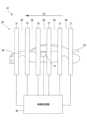
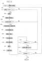
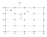
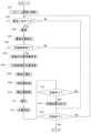
図1は、本発明にかかる欠陥判別装置によって被測定物の一例である車両の欠陥の判別を行っている状態を示す概略図である。図2は、本発明にかかる欠陥判別装置の構成を示すブロック図である。図3は、図1に示す車両の表面に形成される欠陥の一例を示す概略図である。なお、図3は、車両CAの表面の断面図であるが、断面を示すハッチングは省略している。図1に示すように、本実施形態における欠陥判別装置A1では、被測定物の一例として車両CAの表面の欠陥の判別を行う。また、本実施形態の欠陥判別装置A1では、車両CAの側面CPを被検査領域として、側面CPの欠陥の判別を行う。なお、以下の説明において、被検査領域CP又は側面CPと表記する場合がある。<First Embodiment>
FIG. 1 is a schematic diagram showing a state in which a defect of a vehicle, which is an example of an object to be measured, is being discriminated by a defect discriminating apparatus according to the present invention. FIG. 2 is a block diagram showing the configuration of the defect discriminating apparatus according to the present invention. FIG. 3 is a schematic diagram showing an example of defects formed on the surface of the vehicle shown in FIG. Although FIG. 3 is a cross-sectional view of the surface of the vehicle CA, hatching indicating the cross section is omitted. As shown in FIG. 1, the defect discrimination apparatus A1 in this embodiment discriminates surface defects of a vehicle CA as an example of an object to be measured. Further, in the defect determination apparatus A1 of the present embodiment, defects of the side CP of the vehicle CA are determined using the side CP of the vehicle CA as an inspection area. In addition, in the following description, the area to be inspected CP or the side surface CP may be referred to.
通常、車両CAの表面は塗装が施される。車両CAの塗装は、単層構造の場合もあるし、あるいは、2層構造の場合もある。例えば、車両CAの塗装が、2層構造である場合、第1塗装層は、メタリック層CMであり、第1塗装層の上層の第2塗装層は、クリア層CLとすることができる。また、さらに多層構造の場合もある。車両CAの表面の塗装を行うとき、塗料が多すぎたり、メタリック層CMとクリア層CLとの間に塵、埃等の異物DTが侵入したりして、図3に示すように表面が周囲よりも突出する場合がある。このような盛り上がり部分を、本実施形態では、欠陥Dpとする。なお、車両CAの表面の欠陥としては、多すぎた塗料が流れて形成されるものや、吹き付けた塗料の勢いで吹き飛ばされて形成されるもの等もある。詳細は後述するが、本実施形態の欠陥判別装置A1はこれらの欠陥についても、判別可能である。以下の説明では、他の部分より盛り上がった欠陥Dpが形成されるものとして説明する。 The surface of the vehicle CA is usually painted. The coating of the vehicle CA may be a single-layer structure or a two-layer structure. For example, when the vehicle CA has a two-layer structure, the first coating layer can be the metallic layer CM, and the second coating layer above the first coating layer can be the clear layer CL. Moreover, there is also a case of a multi-layered structure. When the surface of the vehicle CA is painted, the amount of paint applied may be excessive, or foreign matter DT such as dust may enter between the metallic layer CM and the clear layer CL. may stand out more than Such a raised portion is defined as a defect Dp in this embodiment. It should be noted that defects on the surface of the vehicle CA include those formed by too much paint flowing, and those formed by being blown away by the momentum of the sprayed paint. Although the details will be described later, the defect determination apparatus A1 of this embodiment can also determine these defects. In the following explanation, it is assumed that the defect Dp is formed so as to be raised from other portions.
<欠陥判別装置A1の全体構成>
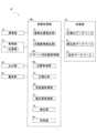
図2に示すように、欠陥判別装置A1は、撮像部10と、照明部20と、記憶部30と、制御処理部40と、出力部50と、搬送部60とを備える。欠陥判別装置A1は、移動している車両CAの側面CP(図1参照)に、照明部20から照明光を照射する。照明光が照射されている被検査領域CPの表面を、撮像部10で撮像して撮像画像を生成する。制御処理部40にて、撮像画像の画像処理を行い、被検査領域CPにおける欠陥の有無を判別する。<Overall Configuration of Defect Discrimination Apparatus A1>
As shown in FIG. 2 , the defect determination apparatus A1 includes an
<撮像部10について>
撮像部10は、CMOS、CCD等の撮像素子を備えている。撮像部10は、いわゆるカメラであり、撮像部10の正面にレンズが設けられている。撮像部10では、照明部20から照射されて被検査領域CPで反射された照明光が撮像素子に入射し、入射光は、撮像素子で結像する。撮像素子は、結像した入射光の像を撮像画像として生成し、撮像部10は生成された撮像画像を制御処理部40に送信する。<Regarding the
The
<照明部20について>
照明部20は、移動方向D1に移動している車両CAの被検査領域CPに向けて照明光を照射する。上述したように、車両CAは、被測定物の一例である。また、被検査領域CPは、車両CAの側面である。照明部20は、被検査領域CPに対して、明部と明部よりも輝度が低い暗部とを交互に配置したパターン照明を投影する。<Regarding the
The
照明部20の詳細について、説明する。図1に示すように、照明部20は、複数個(ここでは、6個)の光源部21を備える。6個の光源部21は、車両CAの移動方向D1に沿って、配列される。光源部21は、それぞれ、車両CAの移動方向と直交する方向に延びる直方体形状である。なお、光源部21の配列は、撮像部10によって出力される撮像画像において、明部Bと暗部Gとが予め決めた間隔、例えば、等間隔に形成されるように配列されている。 Details of the
光源部21は、例えば、平面上に複数個のLEDを二次元配列している。そして、LEDの正面に拡散板が配置される。これにより、LEDから出射された光は拡散される。そして、複数のLEDから出射された光は、拡散板から出射されるときに面内で略均一な輝度の面状の光を出射する。しかしながら、この構成に限定されず。光源部21として、LEDに替えて放電管等の放電発光体や、有機EL等の面状の光源を用いてもよい。 For example, the
各光源部21は、移動方向D1と直交する方向に延びる長方形状の光を車両CAの側面CPに照射する。そして、6個の光源部21の各々から照明光が車両CAの側面CPに照射される。これにより、車両CAの側面CPには、光源部21からの光が照射される明部Bと、光が照射されず明部Bよりも輝度が低い暗部Gとが交互に現れる(図4参照)。すなわち、車両CAの側面CPには、明部Bと暗部Gとが交互に配置されたストライプ状のパターン照明S1が照射される。なお、以下の説明において、光源部21同士の隙間部分を暗帯Gbとする。 Each
図1に示すように、撮像部10と照明部20とは、車両CAに対して同じ側に配置される。そして、撮像部10は、照明部20の中央で、光源部21の間の隙間に配置される。すなわち、撮像部10の左右には、それぞれ、3個ずつ光源部21が配置される。 As shown in FIG. 1, the
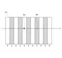
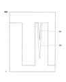
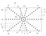
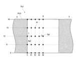
ここで、欠陥判別装置A1の欠陥判別方法について、図面を参照して説明する。図4は、欠陥判別装置で欠陥判別を行っている状態を示す概略平面図である。図5は、パターン照明が照射されている部分を撮像した撮像画像を示す図である。なお、図4、図5では、車両CAの側面CPに2個の欠陥(明部欠陥Dp1、暗部欠陥Dp2)がある場合を示している。図5に示す撮像画像Pc1では、暗部Gにハッチングを施している。 Here, the defect determination method of the defect determination apparatus A1 will be described with reference to the drawings. FIG. 4 is a schematic plan view showing a state in which defect discrimination is being performed by the defect discrimination device. FIG. 5 is a diagram showing a captured image of a portion irradiated with pattern illumination. 4 and 5 show the case where the side CP of the vehicle CA has two defects (light defect Dp1 and dark defect Dp2). In the captured image Pc1 shown in FIG. 5, the dark portion G is hatched.
照明部20から照射されたパターン照明S1は、車両CAの側面CPで反射されて撮像部10に入射する。図4には、照明部20から出射されたパターン照明S1の光路を示す光伝播路を示している。図4において、各光源部21からの光伝播路を一点鎖線で示す。また、欠陥で反射される光伝播路は、太線で示す。なお、以下の説明では、必要に応じて、光伝播路を逆に辿る逆光線追跡にて説明を行う場合がある。 The pattern illumination S<b>1 emitted from the
図4に示すように、照明部20は6個の光源部21から光を照射して、明部Bと暗部Gとが交互に配されたストライプ状のパターン照明S1を車両CAの側面CPに照射している。そして、撮像部10は、パターン照明S1が照射されている側面CPを撮像し、撮像画像Pc1を出力する(図5参照)。撮像画像Pc1には、パターン照明S1による明部Bと暗部Gとが形成される。図2、図4等に示すように、撮像部10は、側面CPで反射されたパターン照明S1による像を撮像画像として出力する。そのため、撮像画像Pc1の明部Bは、光源部21からの光が側面CPで反射されて撮像部10に到った光の像である。一方、光源部21から撮像部10に到った光と光の隙間である。すなわち、暗部Gは、撮像部10から側面CPで反射されて暗帯Gbに到る光伝播路を逆に伝播した光の像である。 As shown in FIG. 4, the
側面CPの表面が略平滑な場合、光伝播路は側面CPで等しく反射する。明部Bの内部では、輝度が均一となる。また、暗部Gも同様に、暗部Gの内部では輝度が均一となる。 If the surface of the side CP is substantially smooth, the light propagation path will reflect equally on the side CP. Inside the bright portion B, the luminance is uniform. Likewise, the brightness of the dark portion G becomes uniform inside the dark portion G.
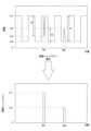
まず、明部Bに欠陥(明部欠陥Dp1)が形成されている場合について説明する。撮像部10から明部欠陥Dp1を含む明部Bに向かう光伝播路は、明部欠陥Dp1でも反射される。このとき、明部欠陥Dp1の表面は、撮像部10に対して周囲の部分と異なる角度の部分を有する。そのため、明部欠陥Dp1に到る光伝播路は、明部欠陥Dp1で乱反射する。その結果、明部欠陥Dp1で反射された光伝播路の照明部20に入射する領域は、明部欠陥Dp1の周囲で反射される光伝播路の照明部20入射する領域とずれる(図4太線で示す)。そして、明部欠陥Dp1で反射された光伝播路の照明部20に入射する領域は、暗帯Gbに含まれる場合がある。そのため、明部欠陥Dp1の撮像画像は、周囲に比べて色が異なる、すなわち、輝度が低くなる場合がある(図5において黒っぽくなる)。なお、輝度は、デジタルカメラ等の撮像装置で撮像される撮像画像において一般的に定義される輝度に限定されない。例えば、光電変換による撮像素子から出力される電圧値、電流値等を含んでよい。すなわち、以下の説明において、「輝度」には撮像画像で一般的に定義される輝度と対応する数値(例えば、電圧値、電流値等)を含むものとする。 First, a case where a defect (bright area defect Dp1) is formed in the bright area B will be described. The light propagation path from the
また、暗部Gに欠陥(暗部欠陥Dp2)が形成されている場合について説明する。撮像部10から暗部欠陥Dp2を含む暗部Gに向かう光伝播路は、暗部欠陥Dp2でも反射される。このとき、暗部欠陥Dp2の表面は、撮像部10に対して周囲の部分と異なる角度の部分を有する。そのため、暗部欠陥Dp2に到る光伝播路は、暗部欠陥Dp2で乱反射する。その結果、暗部欠陥Dp2で反射された光伝播路の照明部20に入射する領域は、暗部欠陥Dp2の周囲で反射される光伝播路の照明部20に入射する領域とずれる(図4太線で示す)。そして、暗部欠陥Dp2で反射された光伝播路の照明部20に入射する領域は、光源部21に含まれる場合がある。そのため、暗部欠陥Dp2の撮像画像は、周囲に比べて色が異なる、すなわち、輝度が高くなる(図5において白っぽくなる)。 Also, a case where a defect (dark-area defect Dp2) is formed in the dark area G will be described. The light propagation path from the
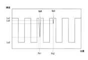
上述したように、欠陥部分では光(光伝播路)は乱反射するため、その周囲に比べて輝度が変化する。欠陥判別装置A1において、欠陥の判別用の判別値として用いる輝度の変化量(輝度コントラスト)について図面を参照して説明する。図6は、図5に示す明部欠陥及び暗部欠陥を通る直線に沿った輝度分布を示す図である。図6に示す輝度分布は、撮像画像の輝度を正規化した後の輝度を示す分布であり、実際には欠陥以外の要因による輝度のブレ(ノイズ)が発生している。制御処理部40は、後述する正規化部45による正規化工程で撮像画像の輝度の欠陥以外の影響を除去し、正規化している。 As described above, light (light propagation path) is diffusely reflected at the defective portion, so that the luminance changes compared to the surroundings. The amount of change in brightness (brightness contrast) used as a determination value for defect determination in the defect determination apparatus A1 will be described with reference to the drawings. FIG. 6 is a diagram showing a luminance distribution along a straight line passing through the bright defect and the dark defect shown in FIG. The luminance distribution shown in FIG. 6 is a distribution indicating the luminance after normalizing the luminance of the captured image, and in reality blurring (noise) in the luminance occurs due to factors other than defects. The
まず、明部Bに形成された明部欠陥Dp1の輝度コントラストの算出方法について説明する。図6に示すように、明部Bの輝度を明部輝度Lu1、暗部Gの輝度を暗部輝度Lu2及び明部欠陥Dp1の輝度を明部欠陥輝度Lu3とする。なお、明部欠陥輝度Lu3としては、明部欠陥Dp1の取り得る輝度の最小値としている。しかしながら、これに限定されず、明部欠陥Dp1の大きさを判別できる値であればよく、異なる数値を用いてもよい。また、明部欠陥Dp1の輝度コントラストを第1輝度コントラストLc1とする。 First, a method for calculating the brightness contrast of the bright defect Dp1 formed in the bright portion B will be described. As shown in FIG. 6, the brightness of the bright portion B is bright portion brightness Lu1, the brightness of the dark portion G is dark portion brightness Lu2, and the brightness of the bright portion defect Dp1 is bright portion defect brightness Lu3. The bright defect brightness Lu3 is the minimum possible brightness of the bright defect Dp1. However, it is not limited to this, and a different numerical value may be used as long as it is a value that can determine the size of the bright defect Dp1. Also, let the luminance contrast of the bright defect Dp1 be a first luminance contrast Lc1.
明部Bと暗部Gの輝度差a1は、次の式で表される。
a1=Lu1-Lu2
また、明部欠陥Dp1の輝度とその周囲の輝度との輝度差b1は、次の式で表される。
b1=Lu1-Lu3
そして、明部欠陥Dp1の第1輝度コントラストLc1は、次の式で表される。
Lc1=b1/a1=(Lu1-Lu3)/(Lu1-Lu2)A luminance difference a1 between the bright portion B and the dark portion G is expressed by the following equation.
a1=Lu1-Lu2
A luminance difference b1 between the luminance of the bright defect Dp1 and the luminance of its surroundings is represented by the following equation.
b1=Lu1-Lu3
The first luminance contrast Lc1 of the bright defect Dp1 is expressed by the following formula.
Lc1=b1/a1=(Lu1-Lu3)/(Lu1-Lu2)
次に、暗部Gに形成された暗部欠陥Dp2の輝度コントラストの算出方法について説明する。図6に示すように、暗部欠陥Dp2の輝度を暗部欠陥輝度Lu4とする。また、暗部欠陥Dp2の輝度コントラストを第2輝度コントラストLc2とする。暗部欠陥Dp2の輝度とその周囲の輝度との輝度差b2は、次の式で表される。
b2=Lu4-Lu2
そして、暗部欠陥Dp2の第2輝度コントラストLc2は、次の式で表される。
Lc2=b2/a1=(Lu4-Lu2)/(Lu1-Lu2)Next, a method for calculating the luminance contrast of the dark defect Dp2 formed in the dark G will be described. As shown in FIG. 6, the brightness of the dark defect Dp2 is assumed to be the dark defect brightness Lu4. Also, the luminance contrast of the dark defect Dp2 is defined as a second luminance contrast Lc2. A luminance difference b2 between the luminance of the dark defect Dp2 and the luminance of its surroundings is expressed by the following equation.
b2=Lu4-Lu2
The second luminance contrast Lc2 of the dark defect Dp2 is expressed by the following equation.
Lc2=b2/a1=(Lu4-Lu2)/(Lu1-Lu2)
制御処理部40は、第1輝度コントラストLc1又は第2輝度コントラストLc2が一定の値(閾値)以上であるか否かで確認して、欠陥の判別を行う。なお、明部欠陥Dp1と暗部欠陥Dp2とが同じ大きさであっても、第1輝度コントラストLc1と第2輝度コントラストLc2の大きさが異なる場合がある。そのため、欠陥が明部Bに形成されている場合と、暗部Gに形成されている場合に分けて、欠陥を判別することが好ましい。例えば、明部欠陥Dp1の場合と暗部欠陥Dp2の場合とで閾値を変更することを挙げることができる。 The
車両CAの側面CPに形成された欠陥の大きさによる輝度の変化について説明する。図7は、大きさの異なる欠陥の輝度分布を示す図である。図7に示すように、車両CAの側面CPの明部Bが形成される部分に、大欠陥DpBと、小欠陥DpSが形成されているものとする。大欠陥DpBは、光伝播路の乱反射が発生する領域が広いため、多くの光伝播路が暗帯Gbに到る。一方で、小欠陥DpSは、光伝播路の乱反射が発生する領域が狭いため、光伝播路の暗帯Gbに到る数が大欠陥DpBよりも少ない。そのため、大欠陥DpBに比べて、小欠陥DpSの輝度コントラストは小さくなる。 A change in brightness depending on the size of the defect formed on the side surface CP of the vehicle CA will be described. FIG. 7 is a diagram showing luminance distributions of defects of different sizes. As shown in FIG. 7, it is assumed that a large defect DpB and a small defect DpS are formed in the portion where the bright portion B of the side face CP of the vehicle CA is formed. Since the large defect DpB has a wide area where irregular reflection occurs in the light propagation path, many of the light propagation paths reach the dark zone Gb. On the other hand, since the small defect DpS has a narrow area where irregular reflection occurs in the optical propagation path, the number of small defects reaching the dark band Gb in the optical propagation path is smaller than that of the large defect DpB. Therefore, the brightness contrast of the small defect DpS is smaller than that of the large defect DpB.
このように、輝度は、欠陥の大きさによって変動する。車両CAの側面CPの表面の輝度が変動する凹凸には、使用者が認識しない程度の微小な凹凸も含まれる。このような微小な凹凸も欠陥として判別すると、製造に要するコストが高くなる。そこで、欠陥判別装置A1では、一定の大きさ以上の凹凸を欠陥として判別する。すなわち、欠陥判別装置A1は、輝度コントラストが一定以上の場合に欠陥と判別する。 Thus, the brightness varies with the defect size. The unevenness of the surface of the side surface CP of the vehicle CA that varies in luminance includes minute unevenness that is not recognized by the user. If even such minute unevenness is determined as a defect, the manufacturing cost increases. Therefore, the defect discriminating apparatus A1 discriminates irregularities of a certain size or larger as defects. That is, the defect discriminating apparatus A1 discriminates as a defect when the brightness contrast is equal to or higher than a certain value.
まず、欠陥判別装置A1の制御処理部40は、撮像画像の輝度の変動から、欠陥の可能性がある凹凸(以下の説明では、欠陥候補と称する)を抽出する。そして、制御処理部40は、欠陥候補と周囲の輝度との変化を示す輝度コントラストを取得し、輝度コントラストが一定値以上(閾値以上)の場合、欠陥候補が欠陥であると判別する。なお、閾値は、被検査領域CPの撮像部10に対する形状が基準となる部分に形成された基準となる大きさの欠陥の輝度コントラストと同じかそれよりもわずかに低い値である。欠陥の判別方法の詳細については、後述する。 First, the
また、欠陥の輝度は、被検査領域CPの欠陥が形成されている部分の撮像部10に対する形状によってもばらつく。次に、被検査領域CPの撮像部10に対する形状による欠陥の輝度のばらつきについて説明する。なお、ここで、欠陥が形成された被検査領域CPの撮像部10に対する形状としては、撮像部10と被検査領域CPに形成された欠陥までの距離、撮像部10に対する被検査領域CPの角度、撮像部10の合焦位置から被検査領域CPまでの距離のずれを挙げることができる。なお、これら以外も形状として含んでもよい。 In addition, the brightness of the defect also varies depending on the shape with respect to the
まず、撮像部からの距離による欠陥の輝度のばらつきについて図面を参照して説明する。図8は、撮像部から欠陥までの距離が異なる場合の光伝播路を示す図である。ここでは、撮像部10から近い欠陥を近欠陥DpN、遠い欠陥を遠欠陥DpFとする。図8に示すように、近欠陥DpNと遠欠陥DpFを比べると、近欠陥DpNで反射される光伝播路は、遠欠陥DpFで反射される光伝播路に比べて短い。 First, variations in brightness of a defect depending on the distance from the imaging unit will be described with reference to the drawings. FIG. 8 is a diagram showing light propagation paths when the distances from the imaging section to the defect are different. Here, let a near defect DpN be a defect close to the
それぞれの光伝播路を比べると、遠欠陥DpFで反射される光伝播路の照明部20に到達する領域は、近欠陥DpNで反射される光伝播路の照明部20に到達する領域に比べて広い。これにより、遠欠陥DpFで反射される光伝播路の暗帯Gbに到達する量は近欠陥DpNで反射される光伝播路の暗帯Gbに到達する量に比べて少なくなる。そのため、近欠陥DpNでは、乱反射による輝度の低下が遠欠陥DpFに比べて抑制される。すなわち、欠陥の大きさが同じ場合、近欠陥DpNの輝度コントラストと遠欠陥DpFの輝度コントラストはばらつく。 Comparing the respective light propagation paths, the area reaching the
図8では、欠陥までの距離が長い方が、輝度コントラストが大きくなる例について説明したが、これに限定されない。例えば、欠陥で反射された光伝播路の照明部に入射した領域が光源部21と暗帯Gbとの境界である位置の場合、被検査領域の撮像部10からの距離を長くすると、その欠陥で反射された光伝播路の一部は、隣の光源部21に達する。そのため、撮像部10からの距離を長くすることで、輝度コントラストが大きくなる場合もある。 FIG. 8 illustrates an example in which the luminance contrast increases as the distance to the defect increases, but the present invention is not limited to this. For example, when the region of the light propagation path that is reflected by the defect and is incident on the illumination section is located at the boundary between the
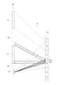
次に、被検査領域CPの撮像部10に対する角度が変化した場合について説明する。撮像部10と正対した被検査領域CPに形成された欠陥で反射された光伝播路と、撮像部10に対して傾いた被検査領域に形成された欠陥で反射された光伝播路とは異なる。すなわち、撮像部10に正対した被検査領域に形成された欠陥で反射される光伝播路が、照明部20の例えば領域αに入射するとする。撮像部10に対して傾いた被検査領域に形成された欠陥で反射される光伝播路が、照明部20の例えば領域βに入射するとする。このとき、領域αと領域βが異なる領域となる。そして、領域αと領域βの光源部21にかかる面積と暗帯Gbにかかる面積とが異なる場合、各欠陥の大きさが同じであっても輝度コントラストが異なる。つまり、欠陥の輝度コントラストは、欠陥が形成されている被検査領域の撮像部10に対する角度が異なることで、変動する場合がある。 Next, a case where the angle of the inspection area CP with respect to the
また、撮像部10には、光学レンズが設けられている。そして、撮像部10では、同一条件で撮像を行うために焦点距離やf値を固定して撮像を行う場合がある。このような場合において、欠陥の撮像部10に対する距離によっては、合焦位置からずれる場合がある。このような場合、撮像画像における欠陥の像はぼやけるになり(輪郭が不鮮明で広がった像になり)、輝度コントラストが変化する場合がある。 Further, the
そして、被測定物である車両CAの側面CPは、立体的な形状を有しており、側面CPの場所によって、撮像部10からの距離、撮像部10に対する角度、合焦位置からの距離が変化する。そのため、車両CAの側面CPの撮像部10に対する形状によって輝度コントラストがばらつく。車両CAの側面CPの撮像部10に対する形状による輝度コントラストのばらつきがあると、欠陥の判別を正確に行うことが困難になる。そこで、本実施形態にかかる制御処理部40では、記憶部30に形状による輝度コントラストのばらつきを抑制する補正値を備え、形状に合わせて輝度コントラストを補正して欠陥の判別を行っている。 The side CP of the vehicle CA, which is the object to be measured, has a three-dimensional shape. Change. Therefore, the brightness contrast varies depending on the shape of the side face CP of the vehicle CA with respect to the
実際の撮像画像では、欠陥(凹凸)以外の原因で輝度がばらつくことがある。そして、正確な輝度コントラストを取得するために、欠陥判別装置A1では、撮像画像の輝度を正規化し、正規化した輝度を用いて欠陥の判別に必要な判別値である輝度コントラストを求めている。以下に、欠陥の判別に必要な情報を記憶する記憶部30及び制御処理部40の詳細について説明する。 In an actual captured image, luminance may vary due to causes other than defects (unevenness). In order to obtain an accurate brightness contrast, the defect discrimination apparatus A1 normalizes the brightness of the captured image, and uses the normalized brightness to obtain the brightness contrast, which is a discrimination value necessary for defect discrimination. Details of the
<記憶部30について>
図2に戻り、記憶部30の説明を行う。記憶部30は、制御処理部40が実行する制御プログラムや各種の情報を記憶するメモリである。記憶部30は、例えば不揮発性の記憶素子であるROM(Read Only Memory)や書き換え可能な不揮発性の記憶素子であるEEPROM(Electrically Erasable Programmable Read Only Memory)等を備える。記憶部30は、前記所定のプログラムの実行中に生じる情報等を記憶するいわゆる制御処理部40のワーキングメモリとなるRAM(Random Access Memory)等を含む。<Regarding the
Returning to FIG. 2, the
記憶部30には、撮像画像の輝度を正規化するためのパラメータを備えた正規化データベース31と、欠陥の判別に必要な補正値を記憶する補正用データベース32と、車両CAの形状情報を記憶する形状データベース33とを備える。 The
被検査物の形状情報は、車両CAの外観を数値化した情報である。上述したとおり、本実施形態において、被検査物は車両CAである。形状情報は、車両CA(のボディー)の外側輪郭面形状を表す車両輪郭形状の情報を含む。そして、車両CAの外観は、3次元的に変化している場合が多い。そのため、ここでは、形状情報を記憶する形状データベース33は、CAD(Computer-Aided Design)のデータを利用して形成される。なお、本実施形態では、車両輪郭形状情報は、車両全体(車両ボディ全体)の外側輪郭面形状を表す数値であるが、例えば車両ボディの右半分や、ドア部分やバンパー部分等、車両CAの部分ごとに分けて形成されてもよい。 The shape information of the object to be inspected is information obtained by digitizing the appearance of the vehicle CA. As described above, in this embodiment, the object to be inspected is the vehicle CA. The shape information includes vehicle contour shape information representing the outer contour surface shape of (the body of) the vehicle CA. In many cases, the appearance of the vehicle CA changes three-dimensionally. Therefore, here, the
欠陥判別装置A1において、撮像部10は予め決められた位置にある。そのため制御処理部40(後述する、形状情報取得部44)は、車両CAと撮像部10との位置に基づいて、撮像部10に対する位置及び形状の情報を取得可能である。 In the defect discriminating apparatus A1, the
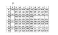
図9は、正規化データベースの一例を示す図である。図9に示すように、正規化データベース31には、撮像画像からノイズを除去するノイズ除去パラメータ311と、明部Bの輝度の代表値を同定する明部同定パラメータ312と、暗部Gの輝度の代表値を同定する暗部同定パラメータ313と、輝度が変化している部分(欠陥候補)の輝度の代表値を同定する変化部同定パラメータ314とを備える。正規化データベース31の各パラメータは、撮像画像の撮像位置ごとに設けられている。すなわち、正規化データベース31は、撮像位置ごとに、ノイズ除去パラメータ311、明部同定パラメータ312、暗部同定パラメータ313及び変化部同定パラメータ314を備える。 FIG. 9 is a diagram showing an example of a normalization database. As shown in FIG. 9, the
なお、ノイズ除去パラメータ311としては、例えば、移動平均の移動量及びローパスフィルタのカットオフ周波数を含んでよい。明部同定パラメータ312としては、例えば、明部Bの輝度の平均値、最頻値、中央値、最大値、最小値算出する演算方法(式)、重み係数及び重み係数を用いた演算方法(式)を含んでよい。暗部同定パラメータ313としては、例えば、暗部Gの輝度の平均値、最頻値、中央値、最大値、最小値を算出する演算方法(式)、重み係数及び重み係数を用いた演算方法(式)を含んでよい。変化部同定パラメータ314としては、輝度が変化している部分の輝度の平均値、最頻値、中央値、最大値、最小値算出する演算方法(式)、重み係数及び重み係数を用いた演算方法(式)を含んでよい。なお、これらの数値、演算方法以外にも、欠陥を判別するための判別値の算出に用いられる数値及び演算方法(式)を広く採用することが可能である。 The
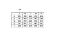
次に、補正用データベース32について説明する。図10は、補正用データベースの形状変数を示す表である。図11は、補正用データベースの一例を示す図である。補正用データベースにおいて、補正値は、形状変数として、距離変数Lg、水平角度変数Hr、鉛直角度変数Vr、合焦点からの距離変数Dsとを含む。 Next, the
図10に示すように、被検査領域CPの距離変数Lgは、基準状態の被検査領域CPに対する距離である。例えば、基準状態よりも撮像部10に近いか遠いかを変数としている。このとき、基準状態から離した被検査領域CPでも、被検査領域CPに焦点を合わせている場合である。なお、撮像部10から決められた距離に撮像部10と正対して配置された被検査領域CPを基準状態とする。 As shown in FIG. 10, the distance variable Lg of the inspection area CP is the distance from the inspection area CP in the reference state. For example, the variable is whether it is closer or farther from the
また、図10に示すように、水平角度変数Hrは、基準状態の被検査領域CPに対して鉛直軸Sp1周りに回転したときの回転角である。また、鉛直角度変数Vrは、基準状態の被検査領域CPに対して水平軸Sp2周りに回転したときの回転角である。なお、本実施形態では、直交する2軸周りの基準状態に対する角度を採用しているが、これ以外の軸周りの回転も含んでいてもよい。さらに、合焦点からの距離変数Dsは、焦点位置を基準状態の被検査領域CPに合わせた状態で、被検査領域CPを移動させて基準状態から離した位置である。 Also, as shown in FIG. 10, the horizontal angle variable Hr is the rotation angle when the inspection area CP in the reference state is rotated around the vertical axis Sp1. The vertical angle variable Vr is a rotation angle when the inspection area CP in the reference state is rotated around the horizontal axis Sp2. In this embodiment, angles about two orthogonal axes with respect to the reference state are used, but rotations about other axes may also be included. Further, the distance variable Ds from the in-focus point is the position where the inspection area CP is moved away from the reference state while the focus position is aligned with the inspection area CP in the reference state.
図11に示すように、補正用データベース32は、形状変数に対応させた補正値を含む。図11に示す補正用データベース32では、距離変数Lgと合焦点からの距離変数Dsとに関連付けられた第1表Tb1を備える。そして、第1表Tb1の各レコード欄には、水平角度変数Hrと鉛直角度変数Vrとに関連付けられた補正値CRijkm(i、j、k、mは、整数)が格納された第2表Tbijを備える。なお、i、jは、それぞれ、距離変数Lg及び合焦点からの距離変数Dsを表す変数である。k、mは、水平角度変数Hr及び鉛直角度変数Vrを表す変数である。 As shown in FIG. 11, the
このように、補正値CRijkmは、4個の形状変数、すなわち、距離変数Lg、合焦点からの距離変数Ds、水平角度変数Hr及び鉛直角度変数Vrに基づいて決定される。なお、各補正値CRijkmは、欠陥を形成した平板等を被検査領域CPとして、欠陥判別装置A1で実際に取得した輝度コントラストを用いてもよい。また、各形状変数ごとのモデルを作成して光学シミュレーションにより算出された輝度コントラストを利用してもよい。なお、補正用データベース32は、理解を容易にするために図11に示すような構成としているが、4個の変数を同時に変更可能なデータベースであれば、この構成に限定しない。 Thus, the correction value CRijkm is determined based on four shape variables, ie, the distance variable Lg, the distance variable Ds from the in-focus point, the horizontal angle variable Hr, and the vertical angle variable Vr. For each correction value CRijkm, the brightness contrast actually obtained by the defect discrimination apparatus A1 may be used with a flat plate or the like on which a defect is formed as the inspected region CP. Alternatively, a model may be created for each shape variable and the luminance contrast calculated by optical simulation may be used. Although the
また、実際の形状情報から、補正用データベース32から直接、補正値CRijkmを求めることが困難な場合がある。このような場合、実際の形状情報に近い形状情報の補正値から、補間して補正値を取得してもよい。なお、図11に示す補正用データベース32は、データベースの一例でありこれに限定されない。例えば、補正値は、補正係数を用いた演算式で与えられてもよい。つぎに、記憶部30に記憶された補正用データベース32及び形状データベース33を用いて欠陥の判別を行う制御処理部40の詳細について説明する。 Further, it may be difficult to obtain the correction value CRijkm directly from the
<制御処理部40について>
図2に戻り、制御処理部40の詳細についての説明を行う。制御処理部40は、欠陥判別装置A1の各部を制御する。制御処理部40は、撮像部10と、照明部20と、記憶部30と、出力部50と、搬送部60と接続して、各部を制御する。制御処理部40は、演算を実行するための演算部を備える。演算部は、CPU、MPU等の演算回路を含む回路である。演算部は、回路自体で演算を行う構成であってもよい。また、例えば、記憶部30から読み込まれたプログラム又は演算部自体に備えられたプログラムを動作させて演算を行ってもよい。制御処理部40は、演算部による演算結果に基づいて、撮像部10、照明部20、出力部50及び搬送部60を制御する。<Regarding the
Returning to FIG. 2, the details of the
また、制御処理部40は、撮像画像に基づいて被検査領域CPの表面の欠陥の有無を判別する。表面の欠陥が判別された場合、制御処理部40は、被検査領域CPにおける欠陥がある部分を特定する。そして、制御処理部40は、被検査領域CPの欠陥の場所を出力部50に表示させる。 Further, the
図1に示すように、制御処理部40は、撮像位置検出部41、欠陥候補検出部42と、位置取得部43と、形状情報取得部44と、正規化部45、判別値取得部46と、補正値取得部47と、補正部48と、判別部49とを備える。なお、制御処理部40の上述の各部は、いずれも処理演算を行う演算回路であってよい。また、制御処理部40の上述の各部の少なくとも一部は、記憶部30に記憶されるとともに制御処理部40で実行される各処理を実行するプログラムであってよい。さらに、プログラムである場合、非一時的な記録媒体に記録された状態で提供されて、制御処理部40を含む欠陥判別装置A1で動作するものであってよい。 As shown in FIG. 1, the
撮像位置検出部41は、撮像部10からの撮像画像が車両CAの側面CPにおける位置である撮像位置を検出する。撮像位置検出部41は、車両CAと撮像部10との相対的な位置関係及び撮像部10の撮像範囲の情報を予め取得している。そして、これらの情報から、撮像画像が撮像した撮像範囲の側面CPにおける位置である撮像位置を取得する。 The imaging
欠陥候補検出部42は、欠陥候補の有無を検出する。欠陥候補検出部42は、欠陥候補があるときには、撮像画像における欠陥候補の位置を特定する。欠陥候補検出部42による欠陥候補を検出する処理としては、上述したような、周囲と異なる色の部分を欠陥候補として検出する処理を挙げることができる。また、予め与えられた欠陥のモデルの情報とマッチングを行って欠陥候補を検出するマッチング処理を用いてもよい。さらには、欠陥候補を精度よく検出できる処理方法を広く採用することができる。 The defect
位置取得部43は、撮像画像の車両CAの側面における位置と撮像画像における欠陥候補の位置の情報に基づいて、欠陥候補の車両CAの側面CPにおける位置の情報を取得する。位置取得部43の位置情報の取得方法についてさらに説明する。上述のとおり、欠陥判別装置A1において、撮像部10の位置は、予め決められている。撮像部10は、画角が決められており撮像画像における欠陥候補の位置と、撮像部10の画角とを組み合わせることで、欠陥候補の被検査領域CPにおける位置を取得できる。 The
車両CAは、外形が3次元的に変形しており、撮像部10に対する形状が一定ではない。そのため、側面CPにおける欠陥候補の輝度は、欠陥候補が形成される場所の撮像部10対する形状によってばらつく。そこで、形状情報取得部44は、欠陥候補の側面CPにおける位置の情報に基づいて、側面CPにおける欠陥候補が形成されている位置の撮像部10に対する形状の情報(形状情報)を取得する。形状情報は、撮像部10に対する角度、撮像部10からの距離、撮像部10の合焦位置からのずれ距離等を挙げることができるが、これに限定されない。これらのうち一つを備えていてもよいし、これら以外にも形状的な特徴を示すとともに、輝度に影響する形状の情報を含んでいてもよい。形状情報取得部44は、記憶部30に記憶された形状データベース33と欠陥候補の側面CPにおける位置の情報に基づいて、欠陥候補がある位置の撮像部10に対する形状情報を取得する。 The vehicle CA has a three-dimensionally deformed outer shape, and the shape with respect to the
正規化部45は、撮像画像の輝度を正規化する。撮像画像の輝度は上述したように欠陥(凹凸)によって変動する。なお、輝度の正規化とは、撮像画像の輝度において、ノイズ等、欠陥の判別に不要な要因による輝度のばらつきを取り除く処理である。すなわち、撮像画像には、凹凸(欠陥候補)以外の原因による輝度のばらつき(電気回路、光学機器が原因のばらつき、以下ノイズと称する)が形成される。そこで、正規化部45は、撮像位置毎にパラメータを備える正規化データベース31から、輝度の正規化に必要なパラメータを呼び出して、輝度の正規化を行う。 The
輝度の正規化には、例えば、ノイズの除去が含まれる。また、明部B及び暗部Gの輝度もばらつく場合がある。このようなばらつきも、パラメータを用いて正規化して明部Bの輝度の代表値、暗部Gの輝度の代表値、輝度の変化部分(欠陥候補)の輝度の代表値を算出する。各輝度の代表値としては、最頻値、平均値、最大値、最小値、中央値、決められた重み係数を用いた算出値を挙げることができるが、これに限定されない。 Brightness normalization includes, for example, noise removal. Moreover, the brightness of the bright portion B and the dark portion G may also vary. Such variations are also normalized using parameters to calculate the representative value of the luminance of the bright portion B, the representative value of the luminance of the dark portion G, and the representative value of the luminance of the luminance change portion (defect candidate). Examples of the representative value of each brightness include, but are not limited to, a mode, average, maximum, minimum, median, and a calculated value using a predetermined weighting factor.
判別値取得部46は、欠陥候補が欠陥か否か判別するための判別値を取得する。判別値取得部46において、判別値は欠陥候補の輝度の周囲輝度に対する変化量(輝度コントラスト)を採用している。判別値取得部46は、正規化された撮像画像及び欠陥候補の位置の情報から、欠陥候補の輝度コントラストを判別値として取得する。すなわち、判別値取得部46は、上述した数式と、明部Bの輝度の代表値、暗部Gの輝度の代表値、欠陥候補の輝度の代表値を利用して、輝度コントラストを算出する。 The discrimination
なお、本実施形態では、判別値として輝度コントラストを用いているが、これに限定されない。例えば、図7に示す輝度分布において、所定の輝度値LuSの輝度分布と交差する部分の画素数を判別値としてもよい。例えば、図7において、大欠陥DpBと交差する部分の画素数Px1と、小欠陥DpSと交差する部分の画素数Px2とを、各欠陥における判別値としてもよい。また、欠陥部分と所定の輝度値LuSとの差分を積分した積分値を用いてもよい。また、判別値としてこのような数値を用いる場合には、これらの数値に対応した閾値が用いられる。 In this embodiment, the luminance contrast is used as the discrimination value, but the present invention is not limited to this. For example, in the luminance distribution shown in FIG. 7, the number of pixels in a portion intersecting with the luminance distribution of the predetermined luminance value LuS may be used as the discrimination value. For example, in FIG. 7, the number of pixels Px1 in the portion intersecting the large defect DpB and the number Px2 of pixels in the portion intersecting the small defect DpS may be used as the discrimination values for each defect. Alternatively, an integrated value obtained by integrating the difference between the defect portion and the predetermined luminance value LuS may be used. Further, when such numerical values are used as discrimination values, threshold values corresponding to these numerical values are used.
上述したように、側面CPの外形は、撮像部10に対する位置によって撮像部10に対する形状が変化する。欠陥候補の大きさが同じであっても、側面CPにおける欠陥候補の位置が異なると欠陥候補の輝度にばらつきが生じる。そこで、補正値取得部47は、記憶部30の補正用データベース32にアクセスし、形状情報を参照して補正値を取得する。補正値は、判別値取得部46で取得した判別値である輝度コントラストを補正するための補正係数である。 As described above, the outer shape of the side surface CP changes in shape with respect to the
補正部48は、欠陥候補の輝度コントラストを補正値で補正する。判別部49は、欠陥候補が欠陥であるか否か判別する。欠陥候補は、外径が大きくなるほど輝度コントラストが大きくなる。そのため、判別部49は、閾値を設定し、補正輝度コントラストと比較することで、欠陥候補が欠陥であるか否か判別する。制御処理部40は、撮像部10が撮像した撮像画像に対して、以上の処理を施すことで、被検査領域CPの欠陥を判別する。 The
そして、制御処理部40は、判別部49が欠陥であると判別した欠陥を被検査領域CPにおける位置を示す判別位置表示画像を生成する。 Then, the
<出力部50について>
出力部50は、例えば、液晶パネル等の表示パネルを含む。出力部50は、制御処理部40と接続されており、出力部50は、撮像部10で撮影した撮影画像、制御処理部40で生成した判別位置表示画像を表示できる。また、出力部50には、タッチパネルが取り付けられていてもよい。タッチパネルが取り付けられていることで、タッチパネルを用いて作業者が欠陥判別装置A1の操作や情報の入力等が可能である。また、数字キー等のハードキーを備えていてもよい。また、出力部50は、以上の構成に限定されず、音声によって通知を行う音声通知部(不図示)等を備えていてもよい。さらには、出力部50は、使用者に対して情報を通知することができる機構を広く採用できる。<Regarding the
The
<搬送部60について>
搬送部60は、車両CAを搬送する。搬送部60は、車両CAの側面CPが、撮像部10の撮影範囲を横切るように搬送する。搬送部60は、制御処理部40と接続されており、搬送部60は、搬送されている車両CAの位置及び移動速度を制御処理部40に通知する。なお、制御処理部40は、搬送部60又は別途備えられる車両CAの位置を検出するセンサー(不図示)から、車両CAの移動速度及び位置を取得するようにしてもよい。また、搬送部60から移動速度、センサーから位置を取得してもよいし、両方から移動速度及び位置の情報を取得しつつ、互いに補完して、側面CPの移動速度及び位置の精度を高めるようにしてもよい。さらには、搬送部60は、車両CAを制止させておき、撮像部10及び照明部20を車両に沿って移動させる構成であってもよい。<Regarding the
The
欠陥判別装置A1は、以上の構成を有している。次に欠陥判別装置A1の動作について図面を参照して説明する。図12は、欠陥判別装置の欠陥判別動作を示すフローチャートである。図12に示すように、制御処理部40は、照明部20に指示を送りパターン照明S1の照射を開始する(ステップS101)。そして、搬送部60からの情報に基づいて車両CAが欠陥検出を行う位置、すなわち、車両CAが撮像部10の画角に収まったか否か確認する(ステップS102)。 The defect discriminating apparatus A1 has the above configuration. Next, the operation of the defect discriminating apparatus A1 will be described with reference to the drawings. FIG. 12 is a flow chart showing the defect discrimination operation of the defect discrimination device. As shown in FIG. 12, the
車両CAが撮像部10の画角に収まっていない場合(ステップS102でNoの場合)、車両CAの対象となる欠陥判別が終了したか否か確認する(ステップS115)。対象となる欠陥判別が終了したか否かとは、例えば、車両CAの側面CPの全てにおいて、欠陥判別が行われたか否かで判断される。欠陥判別が終了していない場合(ステップS115でNoの場合)、撮像部10の画角に側面CPの新たな部分が画角に入ったか否かの確認に戻る(ステップS102に戻る)。また、欠陥判別が終了した場合(ステップS115でYesの場合)、制御処理部40は、欠陥判別の処理を終了する。 If the vehicle CA is not within the angle of view of the imaging unit 10 (No in step S102), it is checked whether or not the defect determination for the vehicle CA has been completed (step S115). Whether or not the target defect determination has been completed is determined, for example, by whether or not the defect determination has been performed on all of the side surfaces CP of the vehicle CA. If the defect determination has not ended (No in step S115), the process returns to confirming whether or not a new portion of the side CP has entered the angle of view of the imaging unit 10 (returns to step S102). Further, when the defect determination is completed (Yes in step S115), the
また、車両CAが撮像部10の画角に収まったことを確認すると(ステップS102でYes)、制御処理部40は、撮像部10に指示を送り、車両CAの側面CPを撮像させ、撮像画像Pc1(電子データ:図5参照)を制御処理部40に送る(ステップS103:撮像工程)。 Further, when it is confirmed that the vehicle CA is within the angle of view of the image capturing unit 10 (Yes in step S102), the
なお撮像画像Pc1は、デジタルデータである。例えば、撮像部10の撮像素子の各画素で検出された値(例えば、電圧値)を16ビットでデジタル値に変換したデータである。なお、デジタル値に変換するビット数は、16ビットに限定されない。 Note that the captured image Pc1 is digital data. For example, it is data obtained by converting a value (for example, a voltage value) detected by each pixel of the imaging element of the
撮像位置検出部41は、撮像部10と車両CAの側面CPとの相対位置に基づいて、撮像部10による撮像画像の側面CPにおける撮像位置を検出する(ステップS104:撮像位置検出工程)。 The imaging
欠陥候補検出部42は、撮像画像を確認し、欠陥の可能性がある部分(欠陥候補)の有無を検出する(ステップS105:欠陥候補検出工程)。撮像画像において欠陥候補は、図5に示すように、周囲と異なる色(輝度)で現れる。例えば、撮像画像の明部Bに欠陥がある場合、欠陥は明部Bの他の部分よりも暗く(輝度が低く)現れる。また、撮像画像の暗部Gに欠陥がある場合、欠陥は暗部Gの他の部分よりも明るく(輝度が高く)現れる。欠陥候補検出部42は、撮像画像において、輝度が変化している領域を、欠陥候補として検出する。 The defect
欠陥候補が無い場合(ステップS105でNoの場合)、車両CAの対象となる欠陥判別が終了したか否か確認する(ステップS115)。対象となる欠陥判別が終了したか否かとは、例えば、車両CAの側面CPの全てにおいて、欠陥判別が行われたか否かで判断される。欠陥判別が終了していない場合(ステップS115でNoの場合)、撮像部10の画角に側面CPの新たな部分が画角に入ったか否かの確認に戻る(ステップS102に戻る)。また、欠陥判別が終了した場合(ステップS115でYesの場合)、制御処理部40は、欠陥判別の処理を終了する。 If there is no defect candidate (No in step S105), it is checked whether or not the defect determination for the vehicle CA has been completed (step S115). Whether or not the target defect determination has been completed is determined, for example, by whether or not the defect determination has been performed on all of the side surfaces CP of the vehicle CA. If the defect determination has not ended (No in step S115), the process returns to confirming whether or not a new portion of the side CP has entered the angle of view of the imaging unit 10 (returns to step S102). Further, when the defect determination is completed (Yes in step S115), the
欠陥候補検出部42によって側面CPに欠陥候補が検出された場合(ステップS105でYesの場合)、位置取得部43は、撮像画像における欠陥候補の位置と撮像位置とに基づいて、欠陥候補の側面CPにおける位置の情報である位置情報を取得する(ステップS106:位置取得工程)。 When the defect
形状情報取得部44は、位置取得部43からの欠陥候補の車両CAの側面CPにおける位置の情報に基づいて、車両CAの側面CPにおける欠陥候補が形成されている部分の撮像部10に対する形状情報を取得する(ステップS107:形状情報取得工程)。形状情報としては、上述したとおり、側面CPの撮像部10に対する距離、撮像部10に対する角度、合焦位置からの距離を備える。 The shape
正規化部45は、正規化データベース31を参照し撮像位置に対応したパラメータを取り出す。そして、取出したパラメータに基づいて撮像画像Pc1の輝度を正規化する(ステップS108:正規化工程)。輝度を正規化する正規化工程には、撮像画像における輝度の変動の欠陥候補の凹凸以外の影響を除去するノイズ除去処理を含む。ノイズ除去処理は、例えば、ローパスフィルタを用いて、撮像画像の輝度のばらつきの高周波成分をカットし、欠陥又は欠陥候補による輝度の変化の成分を抽出する。なお、ローパスフィルタのカットオフ周波数は、正規化データベース31に記憶されている。また、ローパスフィルタに限定されず、一定周波数帯をカットするバンドパスフィルタを用いてもよい。 The
また、撮像画像における明部Bの輝度の代表値、暗部Gの輝度の代表値、欠陥候補の輝度の代表値を決定する処理も含む。なお、正規化データベース31のパラメータは、変数を含むとともに、各部の輝度の代表値を演算する処理に用いられる演算式を含む。 It also includes a process of determining the representative value of the brightness of the bright portion B, the representative value of the brightness of the dark portion G, and the representative value of the brightness of the defect candidate in the captured image. It should be noted that the parameters of the
判別値取得部46は、正規化部45から明部Bの輝度の代表値、暗部Gの輝度の代表値、欠陥候補の輝度の代表値を受け取り、各代表値に基づいて欠陥候補の輝度とその周囲の輝度に対する変化率である輝度コントラストを判別値として取得する(ステップS109:判別値取得工程)。輝度コントラストの算出は、上述した数式により求められる。 The discriminant
補正値取得部47は、形状情報取得部44からの形状情報を受け取るとともに、受け取った形状情報と記憶部30に記憶されている補正用データベース32とを参照して、形状情報に対応した補正値を取得する(ステップS110:補正値取得工程)。 The correction
補正部48は、判別値取得部46からの欠陥候補の輝度コントラストと補正値取得部47からの補正値とに基づいて、欠陥候補の輝度コントラストを補正した補正輝度コントラストを生成する(ステップS111:補正工程)。なお、補正値は、基準となる形状に対して輝度コントラストの変化の割合を示す。そのため、補正工程では、欠陥候補の輝度コントラストに補正値を乗算して補正輝度コントラストを求める。このようにして求められた補正輝度コントラストは、各欠陥候補を基準となる部分に形成したときの輝度コントラストと同等の値を得ることができる。 The
また、欠陥候補が形成されている部分の形状が、基準となる形状に対して2つ以上の変数(ここでは、距離、角度、合焦点からの距離)が異なる場合もある。そのような場合、複数の補正値を輝度コントラストにそれぞれ乗算して補正輝度コントラストを求めてもよい。あるいは、別途与えられている演算式に基づいて、複数の補正値から合成した合成補正値を算出し、合成補正値を用いて補正輝度コントラストを求めてもよい。演算式としては、例えば、形状に基づく補正値に重みづけして、総和を算出する方法を挙げることができる。この場合、重みについても記憶部30に記憶しておき、補正部48が読み込むようにしてもよい。 In addition, the shape of the portion where the defect candidate is formed may differ from the reference shape in two or more variables (here, distance, angle, distance from focal point). In such a case, the corrected luminance contrast may be obtained by multiplying the luminance contrast by a plurality of correction values. Alternatively, a synthetic correction value synthesized from a plurality of correction values may be calculated based on an arithmetic expression provided separately, and the corrected brightness contrast may be obtained using the synthetic correction value. As an arithmetic expression, for example, a method of weighting the correction values based on the shape and calculating the total sum can be used. In this case, the weight may also be stored in the
判別部49は、補正輝度コントラストと予め与えられている閾値とを比較して、欠陥候補が欠陥であるか否か判別(欠陥を判別)する(ステップS112:判別工程)。判別部49は、補正輝度コントラストと閾値とを比較し、補正輝度コントラストが閾値を超えたときに、欠陥候補が欠陥であると判別する。そして、判別部49は、撮像画像CPにおける欠陥の有無を確認する(ステップS113)。 The
判別部49が、欠陥が無いと判別した場合(ステップS113でNoの場合)、車両CAの対象となる欠陥判別が終了したか否か確認する(ステップS115)。対象となる欠陥判別が終了したか否かとは、例えば、車両CAの側面CPの全てにおいて、欠陥判別が行われたか否かで判断される。欠陥判別が終了していない場合(ステップS115でNoの場合)、撮像部10の画角に側面CPの新たな部分が画角に入ったか否かの確認に戻る(ステップS102に戻る)。また、欠陥判別が終了した場合(ステップS115でYesの場合)、制御処理部40は、欠陥判別の処理を終了する。 When the
また、少なくともひとつの欠陥候補を欠陥と判別した場合(ステップS113でYesの場合)、制御処理部40は、欠陥と判別した欠陥候補の車両CAの側面CPにおける位置の情報と、欠陥の大きさの情報を出力部50に出力する(ステップS114)。 If at least one defect candidate is determined to be defective (Yes in step S113), the
そして、制御処理部40は、車両CAの対象となる欠陥判別が終了したか否か確認する(ステップS115)。対象となる欠陥判別が終了したか否かとは、例えば、車両CAの側面CPの全てにおいて、欠陥判別が行われたか否かで判断される。欠陥判別が終了していない場合(ステップS115でNoの場合)、撮像部10の画角に側面CPの新たな部分が画角に入ったか否かの確認に戻る(ステップS102に戻る)。また、欠陥判別が終了した場合(ステップS115でYesの場合)、制御処理部40は、欠陥判別の処理を終了する。 Then, the
欠陥判別装置A1では、上述した各工程を含む欠陥判別方法を用いて被測定物の被測定領域における欠陥を判別している。欠陥判別方法は、制御処理部40にそれぞれ電気回路として備えられてもよい。また、各工程をまとめて或いは個別に記憶部30に記憶されて、処理毎に呼び出されるプログラムであってもよい。欠陥判別方法がプログラムである場合、非一時的な記録媒体に記録された状態で提供されて、制御処理部40を含む欠陥判別装置A1で動作するものであってよい。 The defect discrimination apparatus A1 discriminates defects in the measurement area of the object using the defect discrimination method including the steps described above. The defect determination method may be provided as an electric circuit in each of the
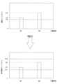
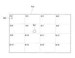
次に本実施形態にかかる欠陥判別装置A1による欠陥判別時の具体的な動作について図面を参照して説明する。図13は、車両の異なる場所で欠陥候補が検出された状態を示す概略図である。図14は、車両で検出された欠陥候補の輝度分布を示す図である。図15は、図14に示す輝度分布から算出した輝度コントラストを補正した補正輝度コントラストを示す図である。なお、図15では、比較を容易にするため、輝度コントラスト及び補正後の輝度コントラストを並べて示す。 Next, specific operations during defect determination by the defect determination apparatus A1 according to this embodiment will be described with reference to the drawings. FIG. 13 is a schematic diagram showing defect candidates detected at different locations on the vehicle. FIG. 14 is a diagram showing luminance distributions of defect candidates detected in a vehicle. FIG. 15 is a diagram showing corrected luminance contrast obtained by correcting the luminance contrast calculated from the luminance distribution shown in FIG. In addition, in FIG. 15, the luminance contrast and the corrected luminance contrast are shown side by side for easy comparison.
欠陥判別装置A1では、搬送部60によって車両CAは搬送されている。そして、搬送される車両CAに対して、照明部20からパターン照明S1を照射する。撮像部10は、制御処理部40からの指示を受け決められタイミングで車両CAの側面CPを撮像する。図13において、車両前方側を第1撮像領域Tp1、車両後方側を第2撮像領域Tp2とする。そして、第1撮像領域Tp1で検出された欠陥候補を第1欠陥候補Dd1、第2撮像領域Tp2で検出された欠陥候補を第2欠陥候補Dd2とする。第1欠陥候補Dd1は、欠陥と判別される大きさであり、第2欠陥候補Dd2は欠陥と判別されない大きさとする。 The vehicle CA is transported by the
図13に示すように、第1欠陥候補Dd1の車両CAの側面CPにおける位置と、第2欠陥候補Dd2の車両CAの側面CPに置ける位置が異なる。そして、正規化部45によって撮像画像に対して輝度の正規化を行った後の輝度の分布は、図14に示すとおりになる。すなわち、第2欠陥候補Dd2の輝度コントラストLd2(輝度の変化量)が、第1欠陥候補Dd1の輝度コントラストLd1よりも大きい。これは、第1欠陥候補Dd1が形成されている側面CPの形状と第2欠陥候補Dd2が形成されている側面CPの形状が異なることが原因である。 As shown in FIG. 13, the position of the first defect candidate Dd1 on the side CP of the vehicle CA differs from the position of the second defect candidate Dd2 on the side CP of the vehicle CA. 14 shows the distribution of luminance after the
そこで、補正値取得部47は、撮像位置検出部41が取得した撮像位置と、形状情報取得部44が取得した形状情報に基づいて、第1欠陥候補Dd1及び第2欠陥候補Dd2が形成された位置の補正値を取得する。そして、補正値に基づいて、第1欠陥候補Dd1及び第2欠陥候補Dd2の輝度コントラストを補正して側面CPの形状の影響を取り除いた補正輝度コントラストを生成する。補正輝度コントラストは、図15に示すようになる。 Therefore, the correction
図15に示すように、第1欠陥候補Dd1の補正輝度コントラストLdr1は、第2欠陥候補Dd2の補正輝度コントラストLdr2よりも大きくなる。そして、判別部49は、第1欠陥候補Dd1の補正輝度コントラストLdr1及び第2欠陥候補Dd2の補正輝度コントラストLdr2を閾値Thと比較する。そして、制御処理部40は、補正輝度コントラストLdr1が閾値Thよりも大きい第1欠陥候補Dd1を、欠陥であると判別する。一方で、制御処理部40は、補正輝度コントラストLdr2が閾値Thよりも小さい第2欠陥候補Dd2を欠陥ではないと判別する。 As shown in FIG. 15, the corrected brightness contrast Ldr1 of the first defect candidate Dd1 is greater than the corrected brightness contrast Ldr2 of the second defect candidate Dd2. Then, the
以上のように、欠陥候補の位置によって補正値を取得し、その補正値で輝度コントラストを補正する。これにより、撮像部10に対する形状が異なることによる輝度のばらつきを補正して、欠陥の判別を正確に行うことができる。 As described above, the correction value is acquired according to the position of the defect candidate, and the luminance contrast is corrected with the correction value. This makes it possible to correct variations in brightness due to differences in shape with respect to the
判別値として、輝度コントラストを用いることで、判別値の比較が容易である。また、輝度コントラストとすることで、塗装色による明部輝度、暗部輝度が異なる場合であっても、精度よく欠陥を判別することができる。なお、本実施形態では、判別値として輝度コントラストを求めているが、これに限定されない。例えば、輝度分布における、輝度が変化している部分の幅、輝度が変化している部分の輝度の変化量の積分値等、輝度が変化している部分の特徴を表す値を用いることも可能である。 By using luminance contrast as the discrimination value, it is easy to compare discrimination values. In addition, by using brightness contrast, defects can be determined with high accuracy even when the brightness of the bright portion and the brightness of the dark portion differ depending on the paint color. In addition, in the present embodiment, the brightness contrast is obtained as the discrimination value, but the present invention is not limited to this. For example, it is also possible to use a value that represents the characteristics of the portion where the brightness changes, such as the width of the portion where the brightness changes in the brightness distribution, or the integrated value of the amount of change in the brightness of the portion where the brightness changes. is.
上述した欠陥判別装置A1では、補正用データベース32の補正値によって、輝度コントラストを補正することで、形状による輝度コントラストの影響を取り除いている。ここで、補正用データベースの作成方法について説明する。本実施形態では、基準となる大きさの欠陥が形成された被測定物モデルの欠陥の輝度コントラストを実際に測定する。測定結果をもとに補正値を求め、補正用データベース32を作成する。 In the above-described defect determination apparatus A1, the influence of the brightness contrast due to the shape is removed by correcting the brightness contrast using the correction value of the
まず、制御処理部40は、被測定物モデルの欠陥が形成されている部分を撮像部10に対して基準状態となる位置にあることを確認する。制御処理部40は、照明部20を制御して配置された被測定物モデルに対してパターン照明S1を照射させる。制御処理部40は、撮像部10を制御して、被測定物モデルを撮像させる。そして、制御処理部40は、撮像部10からの撮像画像に基づいて欠陥の輝度コントラストを取得し、輝度コントラストの基準値として記憶部30に記憶する。なお、輝度コントラストを取得する工程については、上述の欠陥の判別時に輝度コントラストを取得する工程と同じである。 First, the
制御処理部40は、被測定物モデルの撮像部10に対する形状(距離、角度、合焦点からの距離)の基準状態に対する変化量(形状変数)を確認する。制御処理部40は、撮像部10を制御して、被測定物モデルを撮像させる。そして、制御処理部40は、撮像部10からの撮像画像に基づいて欠陥の輝度コントラストを取得し、輝度コントラストの基準値に対する比率を補正値としてとして形状変数と関連付けて補正用データベース32に記憶する。そして、制御処理部40は、補正用データベース32に設定された全ての形状変数に対応した補正値を補正用データベース32に記憶したか確認する。そして、制御処理部40は、被測定物モデルの撮像部10に対する形状(形状情報)を変更して欠陥の輝度コントラストを取得し、補正値を形状変数と関連付けて補正用データベース32に記憶する。 The
以上のように、欠陥判別装置A1の撮像部10で被測定物モデルを実際に撮像し、さらに、撮像画像から欠陥の輝度コントラストを取得することで、補正用データベース32を作成することが可能である。なお、本実施形態では、被測定物モデルを実際に作成した後、撮像を行った後、実測値に基づいて補正用データベース32を作成した。しかしながら、これに限定されず、光学シミュレーションソフトを用いて算出した欠陥の輝度コントラストに基づいて補正値を取得し、補正用データベース32を作成してもよい。 As described above, the
実測によって補正用データベース32を作成した場合、補正用データベース32に欠陥判別装置A1の個体差(例えば、撮像部10の特性、電気回路の特性に起因するもの)による補正値のばらつきの影響を取り除くことが可能である。また、シミュレーションによって補正用データベース32を作成する場合、被測定物モデルを作成しなくてよく、補正用データベース32の作成に要する手間を省くことが可能である。 When the
<第1変形例>
本実施形態にかかる欠陥判別装置の変形例について図面を参照して説明する。なお、欠陥判別装置の構成は上述の構成と同じであり、実質上同じ部分には同じ符号を付すとともに、同じ部分の詳細な説明は省略する。上述したとおり、同じ大きさの欠陥候補であっても撮像部10に対する形状によって輝度コントラストがばらつく。形状による輝度コントラストのばらつきを取り除くため、補正部48は、補正工程として輝度コントラストを補正することに替えて閾値を補正してもよい。そして、判別工程において、欠陥候補の輝度コントラストと補正した閾値(以下、補正閾値とする)とを比較して、欠陥の判別を行ってもよい。以下に補正工程の詳細について図面を参照して説明する。なお、撮像工程から補正値取得工程までの動作は、図12に示すフローチャートと同じである。<First modification>
A modified example of the defect determination device according to the present embodiment will be described with reference to the drawings. The configuration of the defect discriminating apparatus is the same as the configuration described above, and substantially the same parts are denoted by the same reference numerals, and detailed description of the same parts is omitted. As described above, even for defect candidates of the same size, the brightness contrast varies depending on the shape with respect to the
図16は、欠陥の判別を行うときの欠陥候補の輝度コントラストの補正を示す図である。図16に示す第1欠陥候補Dd1及び第2欠陥候補Dd2は、図15に示す第1欠陥候補Dd1及び第2欠陥候補Dd2と同じ大きさで側面CPの同じ場所に形成されているもとする。また、図16では、比較を容易にするため、第1欠陥候補Dd1と第2欠陥候補Dd2とを並べて表示している。 16A and 16B are diagrams showing correction of luminance contrast of defect candidates when performing defect discrimination. FIG. It is assumed that the first defect candidate Dd1 and the second defect candidate Dd2 shown in FIG. 16 are the same size as the first defect candidate Dd1 and the second defect candidate Dd2 shown in FIG. 15 and formed at the same place on the side surface CP. . Also, in FIG. 16, the first defect candidate Dd1 and the second defect candidate Dd2 are displayed side by side for easy comparison.
欠陥判別装置A1において、記憶部30には、基準となる形状において欠陥と判別される最小サイズの欠陥の輝度コントラストと同じかわずかに小さい値を基準閾値ThSとして記憶されている。図16に示すように、第1欠陥候補Dd1の輝度コントラストLd1及び第2欠陥候補Dd2の輝度コントラストLd2は基準閾値ThSよりも大きい。 In the defect discriminating apparatus A1, the
補正部48は、欠陥候補ごと、換言すると、欠陥候補が形成されている部分の形状情報ごとの補正値で、基準閾値ThSを補正した補正閾値を取得する。図16に示すように、第1欠陥候補Dd1に対応した第1補正閾値Thr1と第2欠陥候補Dd2に対応した第2補正閾値Thr2を生成する。そして、判別部49は、各補正閾値と、欠陥候補の輝度コントラストとを比較して欠陥の判別を行う。 The correcting
詳しく説明すると、第1欠陥候補Dd1の輝度コントラストLd1は第1補正閾値Thr1よりも大きい。そのため、判別部49は、第1欠陥候補Dd1を欠陥と判別する。一方、第2欠陥候補Dd2の輝度コントラストLd2は第2補正閾値Thr2よりも小さい。そのため、判別部49は、第2欠陥候補Dd2を欠陥ではないと判別する。 Specifically, the brightness contrast Ld1 of the first defect candidate Dd1 is greater than the first correction threshold Thr1. Therefore, the
このように、比較対象となる輝度コントラストではなく、評価を行う閾値を補正することで、輝度コントラストを補正したときと同様に、正確に欠陥を判別することができる。また、基準閾値ThSの値を変更することで、欠陥と判別される欠陥候補の大きさを調整することが可能である。例えば、欠陥と判別される凹凸の大きさが大きくてもよい場所の場合、基準閾値ThSを大きくすることで、欠陥と判別される欠陥候補の大きさを変更することが可能である。 In this manner, by correcting the threshold for evaluation instead of the luminance contrast to be compared, it is possible to accurately determine the defect in the same manner as when the luminance contrast is corrected. Further, by changing the value of the reference threshold ThS, it is possible to adjust the size of the defect candidate determined as a defect. For example, in the case of a location where the size of unevenness determined as a defect may be large, it is possible to change the size of a defect candidate determined as a defect by increasing the reference threshold value ThS.
なお、欠陥と判別する最小の欠陥候補の形状及び大きさが決まっている場合、補正用データベースは、補正値に替えて補正後の閾値を備えていてもよい。このようにする場合、閾値を補正値で補正する手間が省けるため、欠陥の判別の時間を短くすることが可能である。 Note that if the shape and size of the minimum defect candidate to be determined as a defect are determined, the correction database may include post-correction thresholds in place of the correction values. In this case, the trouble of correcting the threshold value with the correction value can be saved, so that the time required for determining the defect can be shortened.
また、補正値としては、上述した輝度コントラストを補正する補正用データベースをそのまま用いてもよい。この場合、輝度コントラストの補正とは逆の演算とすればよい。例えば、輝度コントラストと補正値を乗算して補正輝度コントラストを算出している場合、輝度コントラストを補正値で除算して補正閾値を算出すればよい。また、輝度コントラストを補正するための補正用データベースを別途備えていてもよい。 Further, as the correction value, the above correction database for correcting the brightness contrast may be used as it is. In this case, the calculation may be the reverse of the correction of the luminance contrast. For example, when the corrected luminance contrast is calculated by multiplying the luminance contrast and the correction value, the correction threshold may be calculated by dividing the luminance contrast by the correction value. Further, a correction database for correcting luminance contrast may be provided separately.
車両CAの表面の塗装色によっては、撮像画像における明部B及び暗部Gの輝度が変動する。例えば、白、銀、黄色等の明るい色の場合、明部Bの輝度が高くなりやすく明部Bと暗部Gとの輝度の差が大きくなりやすい。一方で、黒、紺等の暗い色の場合、明部Bの輝度が低く明部Bと暗部Gとの輝度の差が小さくなりやすい。補正値で閾値を補正する構成の場合、このような異なる色の車両CAの欠陥の判別を行う場合でも、共通の補正用データベースを用いることができる。それだけ、記憶部30の使用領域を少なくできる。そして、補正用データベースの入れ替えが不要であるため制御処理部40による処理を低減できる。 The brightness of the bright portion B and the dark portion G in the captured image varies depending on the paint color of the surface of the vehicle CA. For example, in the case of bright colors such as white, silver, and yellow, the brightness of the bright portion B tends to be high, and the difference in brightness between the bright portion B and the dark portion G tends to be large. On the other hand, in the case of dark colors such as black and navy blue, the brightness of the bright portion B is low, and the difference in brightness between the bright portion B and the dark portion G tends to be small. In the case of the configuration in which the threshold value is corrected by the correction value, a common correction database can be used even when the defects of the vehicles CA of different colors are determined. Accordingly, the used area of the
<第2変形例>
図17は、被測定物に形成された欠陥の断面形状である。欠陥判別装置A1で欠陥を判別する被測定物として車両CAを挙げている。図17に示すように、欠陥としては、塗装時の表面に形成される凹凸としている。通常、車両CAの塗装の最外層には、透明な樹脂のクリア層CLが形成される。そして、クリア層CLの盛り上がりによる凸部が欠陥の一つである。なお、クリア層CLが多いことによる欠陥を透明欠陥Dfと称する。また、欠陥には、クリア層CLとその下のメタリック層CMの間に塵、埃等の異物DTが封入されることでも発生する。異物DTが封入されることによる欠陥を封入欠陥Dhと称する。<Second modification>
FIG. 17 shows the cross-sectional shape of a defect formed in the object to be measured. A vehicle CA is cited as an object to be measured for which defects are determined by the defect determination apparatus A1. As shown in FIG. 17, the defects are irregularities formed on the surface during painting. Usually, a clear layer CL made of a transparent resin is formed as the outermost layer of the coating of the vehicle CA. One of the defects is the protrusion due to the swelling of the clear layer CL. A defect caused by a large amount of the clear layer CL is referred to as a transparent defect Df. Defects also occur when foreign matter DT such as dust is enclosed between the clear layer CL and the underlying metallic layer CM. A defect caused by inclusion of the foreign matter DT is called an inclusion defect Dh.
透明欠陥Dfは、透明なクリア層CLが盛り上がっているだけであり、多少大きくても車両CAの使用者に視認されにくい。すなわち、欠陥と判別されにくい。一方で、封入欠陥Dhの場合、異物が混入しているので、透明欠陥Dfに比べて使用者に視認されやすい。そして、封入欠陥Dhは、異物DTと車両CAの塗装色によって使用者によって視認され易さが異なる場合がある。例えば、白い塗装の車両CAに白い異物DTが封入されたことによる封入欠陥(近似色封入欠陥Dh1とする)は、使用者によって欠陥として視認されにくい。一方で、白い塗装の車両CAに黒い異物DTが封入されたことによる封入欠陥(非近似色封入欠陥Dh2とする)は、使用者によって欠陥として視認されやすい。このように、封入欠陥Dhの場合、異物の色によって欠陥として視認され易さが異なる。 The transparent defect Df is only a raised transparent clear layer CL, and even if it is somewhat large, it is difficult for the user of the vehicle CA to visually recognize it. That is, it is difficult to discriminate as a defect. On the other hand, in the case of the inclusion defect Dh, since foreign matter is mixed, it is more likely to be visually recognized by the user than the transparent defect Df. The easiness of recognizing the enclosed defect Dh may differ depending on the user depending on the foreign matter DT and the paint color of the vehicle CA. For example, an inclusion defect (approximate color inclusion defect Dh1) due to inclusion of a white foreign matter DT in a white-painted vehicle CA is less likely to be visually recognized as a defect by the user. On the other hand, an inclusion defect (referred to as a non-similar color inclusion defect Dh2) due to inclusion of a black foreign matter DT in a white-painted vehicle CA is likely to be visually recognized as a defect by the user. As described above, in the case of the inclusion defect Dh, the susceptibility to visually confirming the defect differs depending on the color of the foreign matter.
そこで、本変形例では、欠陥候補検出部42は、撮像画像Pc1から欠陥候補を検出する。欠陥候補検出部42は、色の変化量の大小によって、欠陥候補が透明欠陥Dfの候補であるか、封入欠陥Dhであるか判断する。さらに、欠陥候補が、封入欠陥Dhの場合、その封入欠陥Dhが近似色封入欠陥Dh1か非近似色封入欠陥Dh2か判別する。 Therefore, in this modified example, the defect
本実施形態の欠陥判別装置A1では、被測定物として車両CAを被検査領域CPとして車両CAの側面CPとしている。しかしながら、車両CAの表面の欠陥を判別する場合、側面以外の部分、例えば、ボンネット、バンパー、天井、トランク等の部分の欠陥の判別も行う。車両CAにおいて、欠陥の位置によって、使用者が判別可能な欠陥の大きさが異なる。例えば、透明欠陥Dfの場合、使用者が車両CAに乗り込むときに、視線に泊まりやすい位置であるドアの上部や、ボンネット等は、天井、ドアの下部に比べて小さい透明欠陥Dfであっても使用者に視認されやすい。 In the defect determination apparatus A1 of the present embodiment, the vehicle CA is used as the object to be measured, and the side surface CP of the vehicle CA is used as the inspection area CP. However, when identifying defects on the surface of the vehicle CA, defects on portions other than the sides, such as the hood, bumper, ceiling, trunk, etc., are also identified. In the vehicle CA, the size of the defect that can be determined by the user differs depending on the position of the defect. For example, in the case of the transparent defect Df, when the user gets into the vehicle CA, the upper part of the door, the hood, etc., which is a position where the user can easily stay in the line of sight, is smaller than the ceiling and the lower part of the door. Easily visible to the user.
そこで、車両CAの領域毎に、欠陥と判別される欠陥候補の種類及び大きさを異なるものとしている。これにより、使用者が判別可能な欠陥を正確に判別できる。このような、欠陥と判別される欠陥候補の種類及び大きさを変更するために、欠陥判別装置A1では、閾値を基準となる欠陥の大きさによってランク付けしている。ここで、閾値の選択に用いられる閾値データベースについて図面を参照して説明する。図18は、閾値データベースを示す図である。 Therefore, the types and sizes of defect candidates determined to be defects are made different for each region of the vehicle CA. As a result, it is possible to accurately determine defects that can be determined by the user. In order to change the types and sizes of defect candidates to be determined as defects, the defect determination apparatus A1 ranks the thresholds according to the size of the defect serving as a reference. Here, the threshold database used for threshold selection will be described with reference to the drawings. FIG. 18 is a diagram showing a threshold database.
図18に示すように、閾値データベース34は、補正用データベースの基準となる位置における欠陥の大きさ(外径)をランク分けしたものである。図18に示すように、閾値データベースには、第1ランクR1~第7ランクR7の7種類のランクに分けられている。そして、第1ランクR1は、外形の小さい欠陥を判別するための閾値Th1を備える。同様に、第2ランクR2~第7ランクR7には、閾値Th2~閾値Th7が備えられる。なお、閾値の大きさは、Th1<Th2<Th3・・・<Th6<Th7となる。 As shown in FIG. 18, the
また、記憶部30には、欠陥を検出する欠陥の大きさランクを示す評価用データベースが備えられる。図19は、評価用データベースの概略図である。欠陥判別装置A1では、車両CAの位置(側面上部、側面化部、ボンネット、バンパー、天井、トランク)によって、また、欠陥の種類(透明欠陥Df、近似色封入欠陥Dh1、非近似色封入欠陥Dh2)ごとに、欠陥と判別する欠陥候補の大きさを変更する。図19に示すように、形状及び種類によって欠陥候補の大きさをランク分けする。 In addition, the
図19に示すように、評価用データベース35は、上下方向に封入欠陥の種類に分けている。また、横方向に車両の位置に分けている。例えば、評価用データベース35において、側面上部では、透明欠陥Dfは第4ランクR4である。また、近似色封入欠陥Dh1は第2ランクR2、非近似色封入欠陥Dh2は第1ランクR1である。 As shown in FIG. 19, the
そして、補正部48及び判別部49は、欠陥候補の位置情報から評価用データベース35を参照して、欠陥と判別する欠陥候補のランクを決定する。そして、閾値データベース34を参照し、決定されたランクに基づく閾値をその欠陥候補を欠陥と判別するための閾値を取得する。例えば、欠陥候補が近似色封入欠陥Dh1であり、欠陥候補がボンネットにある場合、図19を参照して、欠陥の大きさランクを決定する。そして、閾値データベース34を参照し、決定したランクの閾値を欠陥の判別に用いる閾値と決定する。 Then, the
このようにすることで、欠陥候補の位置、種類によって欠陥を判別する閾値を変更することができる。これにより、欠陥候補の位置、種類ごとに欠陥と判別する欠陥候補の大きさを適切なものとして、正確に欠陥の判別を行うことができる。ここでは、閾値をランク分けしているが、これに限定されない。閾値データベースと同様に、ランクごとに重みを設定したデータベースを用い、重みによって補正値を修正するようにしてもよい。 By doing so, it is possible to change the threshold for determining the defect depending on the position and type of the defect candidate. As a result, the size of a defect candidate to be determined as a defect can be set appropriately for each position and type of the defect candidate, and the defect can be accurately determined. Although the thresholds are ranked here, the present invention is not limited to this. Similar to the threshold database, a database in which a weight is set for each rank may be used, and the correction value may be modified according to the weight.
<その他の変形例>
本実施形態では、図12に示すように、判別値取得工程(ステップS109)の前に、撮像画像の輝度の正規化を行う正規化工程(ステップS108)を備えている。しかしながら、これに限定されない。例えば、正規化工程を省いて、撮像画像をデジタル化したデータから直接判別値を取得するようにしてもよい。正規化を行わないため、処理を省くことができる。なお、この場合、欠陥候補(凹凸)以外の要因による撮像画像の輝度のばらつきが少ない場合には、正規化工程を省き、欠陥候補(凹凸)以外の要因による撮像画像の輝度のばらつきが多い場合には、判別値取得工程の前に正規化工程にて正規化を行ってよい。<Other Modifications>
In this embodiment, as shown in FIG. 12, a normalization step (step S108) of normalizing the brightness of the captured image is provided before the discrimination value acquisition step (step S109). However, it is not limited to this. For example, the normalization process may be omitted and the discriminant value may be obtained directly from data obtained by digitizing the captured image. Processing can be omitted because normalization is not performed. In this case, when there is little variation in the brightness of the captured image due to factors other than the defect candidate (unevenness), the normalization process is omitted. may be normalized in the normalization step before the discriminant value acquisition step.
また、上述の実施形態では、1つの撮像画像を撮像するごとに、撮像画像に基づいて欠陥の判別を行っているが、これに限定されない。例えば、被測定物である車両CAを撮像部10及び照明部20に対して相対的に一定距離移動する毎に、画像の撮像を行い蓄積する。そして、車両CAが一定距離移動した又は一定枚数の撮像画像が一定枚数蓄積されたとき、蓄積した画像を合成する。このとき、MAXコントラスト画像、MINコントラスト画像、標準偏差画像を取得して、合成することで、欠陥候補を検出することが可能である。なお、合成方法としては、例えば、MAX-MIN法、標準偏差法、差の二乗による合成方法等の公知の画像合成法を用いることができる。そして、合成によって生成された画像情報に対して、画像処理(例えば、ローカルコントラスト法)を用いて正規化を行う。 Further, in the above-described embodiment, each time one captured image is captured, a defect is determined based on the captured image, but the present invention is not limited to this. For example, every time the vehicle CA, which is the object to be measured, moves by a certain distance relative to the
ここで、ローカルコントラスト法について、詳しく説明する。画像picture(i,j)に対してNx×Nyの移動平均をかけてぼかし画像pictureBlur(i,j)を作成する。演算式は、以下に示す数1である。

なお、合成する画像としては、撮像部10及び照明部20を固定し、車両CAを移動させて撮像を行い、複数枚の撮像画像を取得しているが、これに限定されない。例えば、撮像部10及び照明部20の少なくとも一方を移動させて、撮像を行って複数枚の撮像画像を取得してもよい。また、複数の撮像部10を備えておき、複数の撮像部10で同時に撮像して複数の撮像画像を取得してもよい。なお、画像合成によって、欠陥候補の輝度の変動を明確に検出することができる場合には、正規化工程を省いてもよい。 In addition, although the image to be synthesized is obtained by fixing the
<第2実施形態>
本発明にかかる他の例の欠陥判別装置A2について図面を参照して説明する。図20は、本実施形態にかかる欠陥判別装置の他の例の構成を示すブロック図である。制御処理部40aは、図2に示す制御処理部40の、位置取得部43および形状情報取得部44に替えて画像内位置取得部43aおよび位置取得部44aを備える。制御処理部40aの制御処理部40と同じ部分には、同じ符号を付すとともに、同じ分の詳細な説明は省略する。すなわち、図20に示すように、制御処理部40aは、撮像位置検出部41、欠陥候補検出部42と、画像内位置取得部43aと、位置取得部44aと、正規化部45、判別値取得部46と、補正値取得部47と、補正部48と、判別部49とを備える。記憶部30に記憶された補正用データベースは、後述の図24に示す補正用データベース32aを備えている。<Second embodiment>
Another example of the defect determination apparatus A2 according to the present invention will be described with reference to the drawings. FIG. 20 is a block diagram showing the configuration of another example of the defect discrimination device according to this embodiment. The
画像内位置取得部43aは、欠陥候補検出部42が欠陥候補を検出したときに、撮像画像内における欠陥候補の位置である画像内位置情報を取得する。画像内位置情報は、画素単位の情報であってもよいし、撮像画像を縦横に分割した領域を予め設定しておき、その領域を指定するものであってもよい。さらには、基準点を決めておき、基準点を中心として、半径及び角度で示す極座標系で領域を指定してもよい。また、これら以外の方法で指定してもよい。 The in-image
位置取得部44aは、撮像画像の車両CAの側面における位置と画像内位置情報に基づいて、欠陥候補の車両CAの側面CPにおける位置の情報を取得する。位置取得部44aの位置情報の取得方法についてさらに説明する。上述のとおり、欠陥判別装置A1において、撮像部10の位置は、予め決められている。撮像部10は、画角が決められており撮像画像における欠陥候補の位置と、撮像部10の画角とを組み合わせることで、欠陥候補の被検査領域CPにおける位置を取得する。 The position acquisition unit 44a acquires information on the position of the defect candidate on the side surface CP of the vehicle CA based on the position of the captured image on the side surface of the vehicle CA and the in-image position information. A method of acquiring position information by the position acquisition unit 44a will be further described. As described above, the position of the
上述したように、欠陥候補の大きさが同じであっても、撮像画像Pc2(図22参照)における欠陥候補の位置が異なると欠陥候補の輝度にばらつきが生じる。そこで、補正値取得部47は、記憶部30の補正用データベース32aにアクセスし、画像内位置情報を参照して補正値を取得する。補正値は、判別値取得部46で取得した判別値である輝度コントラストを補正するための補正係数である。欠陥判別装置A2は、以上の構成を有している。 As described above, even if the sizes of the defect candidates are the same, if the positions of the defect candidates in the captured image Pc2 (see FIG. 22) are different, the brightness of the defect candidates varies. Therefore, the correction
欠陥の輝度は、被検査領域CPの欠陥が形成されている部分の撮像画像内における位置によってもばらつく。以下に、撮像画像内における位置による欠陥候補の輝度の変化について図面を参照して説明する。図21は、異なる位置に欠陥候補が形成された撮像画像を示す図である。図22は、撮像画像内の異なる位置に欠陥候補がある場合の欠陥判別を行っている状態を示す概略平面図である。図21に示すように撮像画像Pc2の中央部分に、第1欠陥候補De1が形成されているとともに、左上部分に第2欠陥候補De2が形成されているとする。 The brightness of the defect also varies depending on the position in the captured image of the portion of the inspection area CP where the defect is formed. A change in brightness of a defect candidate depending on the position in the captured image will be described below with reference to the drawings. FIG. 21 is a diagram showing captured images in which defect candidates are formed at different positions. FIG. 22 is a schematic plan view showing a state in which defect determination is performed when defect candidates are present at different positions within a captured image. As shown in FIG. 21, it is assumed that the first defect candidate De1 is formed in the central portion of the captured image Pc2 and the second defect candidate De2 is formed in the upper left portion.
図21に示すように、第1欠陥候補De1と第2欠陥候補De2とでは、欠陥候補から撮像部10に対する距離及び角度が異なる。そのため、撮像部10から出斜し、各欠陥候補で反射した光伝播路は、照明部20の異なる領域に入射する。つまり、第1欠陥候補De1と第2欠陥候補De2とでは、大きさが同じであっても、輝度が異なる。撮像画像内における位置によって判定値の変化の原因として、例えば、欠陥に対する光線角度の差、収差の影響、撮像部と照明部と被測定物との位置関係等を挙げることができるがこれに限定されない。 As shown in FIG. 21 , the first defect candidate De1 and the second defect candidate De2 are different in distance and angle from the defect candidate to the
欠陥候補の輝度コントラストは、撮像画像内における位置によってばらつく。撮像画像内の位置によって欠陥候補の輝度コントラストがばらつくと、欠陥の判別を正確に行うことが困難になる。そこで、本実施形態にかかる制御処理部40aでは、記憶部30に撮像画像内の位置(画像内位置)による輝度コントラストのばらつきを抑制する補正値を備えた補正用データベース32aを備える。そして、制御処理部40aは、欠陥候補の撮像画像内における位置に合わせて輝度コントラストを補正して欠陥の判別を行っている。 The brightness contrast of the defect candidate varies depending on the position within the captured image. If the brightness contrast of the defect candidate varies depending on the position in the captured image, it becomes difficult to accurately determine the defect. Therefore, in the
詳しく説明すると、撮像部10は、外部の光をレンズで撮像素子に集光して、撮像素子に結像した光の像を撮像画像として出力する。そして、撮像画像Pc2における位置は、側面CPの撮像領域Trにおける欠陥候補の位置と対応している。そこで、本実施形態にかかる欠陥判別装置の補正用データベース32aは、撮像画像Pc2における欠陥候補の位置を画像内位置変数として、画像内位置変数ごとの補正値を備える。そして、画像内位置変数に対応した補正値を取得するとともに、補正値にて、輝度コントラストを補正して欠陥の判別を行っている。なお、補正用データベース32aを実測値に基づいて或いはシミュレーションに基づいて生成することで、判定値の変化の要因の多くを取り除くことが可能である。なお、正規化については、第1実施形態と同じであるため、詳細は省略する。 More specifically, the
次に、補正用データベース32aについて説明する。図23は、補正用データベースの画像内位置変数を撮像画像上に示す図である。図24は、補正用データベースの一例を示す図である。 Next, the
上述したように、撮像画像Pc2の位置によって欠陥候補の輝度コントラストがばらつく、そこで、欠陥判別装置A1は、図23に示すように、撮像画像Pc2を上下左右に16等分した分割領域を、第1領域Ar1~第16領域Ar16としている。そして、第1領域Ar1~第16領域Ar16の16の分割領域は、補正用データベース32aの画像内位置変数である。なお、本実施形態では、説明を容易にするため、撮像画像Pc2を16等分しているが、これに限定されない。例えば、25等分、36等分等さらに細かい領域に分割してもよい。また、本実施形態では、縦と横の分割数を同数としているが、これに限定されない。例えば、分割領域を正方形又は任意の形状にし、撮像画像Pc2を分割領域で隙間なく敷き詰めるようにしてもよい。すなわち、欠陥候補が形成されている部分を指定できるような分割領域を広く採用することができる。 As described above, the brightness contrast of the defect candidate varies depending on the position of the captured image Pc2. Therefore, as shown in FIG. 1 region Ar1 to 16th region Ar16. The 16 divided areas of the first area Ar1 to the sixteenth area Ar16 are the in-image position variables of the
図24に示すように、補正用データベース32aは、上段に画像内位置変数として上述の分割領域を、下段に画像内位置変数に対応した補正値CRi(iは1以上の整数である)をそれぞれ備える。例えば、画像内位置変数Ar6の場合、補正値CR6である。すなわち、撮像画像Pc2において、画像内位置変数Ar6に対応する第6領域Ar6(図23参照)にある欠陥の輝度コントラストは、補正値CR6を用いて補正する。 As shown in FIG. 24, the
なお、補正用データベース32の画像内位置変数として、図23に示すような分割領域を用いるものは、一例であり、これに限定されない。 It should be noted that the use of divided areas as shown in FIG. 23 as the intra-image position variable of the
画像内位置変数と補正用データベースの他の例について図面を参照して説明する。図25は、撮像画像における補正用データベースの画像内位置変数を示す図である。図26は、補正用データベースの他の例を示す図である。 Another example of the intra-image position variable and the correction database will be described with reference to the drawings. FIG. 25 is a diagram showing intra-image position variables of a correction database in a captured image. FIG. 26 is a diagram showing another example of the correction database.
図25に示すように、撮像画像Pc2の左下の隅部を原点(0、0)とし、撮像画像Pc2の横方向の辺及び縦方向の辺をそれぞれ等分する。ここでは、横、縦ともに4等分とする。そして、撮像画像Pc2の横方向の辺を等分する点を横方向の画像内位置変数とし原点側から順にX1、X2、X3、X4とする。また、同様に縦方向の辺を等分する点を縦方向の画像内位置変数とし原点側から順にY1、Y2、Y3、Y4とする。すなわち、画像内位置変数は、原点からの距離である。 As shown in FIG. 25, with the lower left corner of the captured image Pc2 as the origin (0, 0), the horizontal and vertical sides of the captured image Pc2 are equally divided. Here, it is divided horizontally and vertically into four equal parts. Then, the points that equally divide the sides of the captured image Pc2 in the horizontal direction are defined as horizontal intra-image position variables and X1, X2, X3, and X4 in order from the origin side. Likewise, the points that equally divide the sides in the vertical direction are set as vertical in-image position variables, and Y1, Y2, Y3, and Y4 are set in order from the origin side. That is, the in-image position variable is the distance from the origin.
図25の各辺を等分する線の交点を、横方向の画像内位置変数と縦方向の画像内位置変数とで示す。例えば、図25における、点K1は、画像内位置変数を用いて(X2、Y3)と表される。そして、補正用データベース32bでは、各交点における補正値CRpq(p、qは整数であり変数)を備える。すなわち、図26に示す補正用データベース32bは、横項目を横方向の画像内位置変数、縦項目を縦方向の画像内位置変数としている。そして、横枠と縦枠とが交差する枠に横項目と縦項目との画像内位置変数で示される点における補正値が配置される。例えば、上述した点K1の場合、横項目X2、縦項目Y3の交差する枠を参照し、補正値は補正値CR23となる。 The intersections of the lines that equally divide each side in FIG. 25 are indicated by the horizontal intra-image position variable and the vertical intra-image position variable. For example, point K1 in FIG. 25 is expressed as (X2, Y3) using the intra-image position variable. The
図26に示す補正用データベース32bは、撮像画像Pc2の点における補正値である。実際に判別される欠陥候補が補正用データベース32bで設定した点と重なることはまれである。そこで、制御処理部40aの画像内位置取得部43aは、欠陥候補の撮像画像Pc2の左下の角を原点とする横方向及び縦方向の位置を位置情報を取得する。そして、位置情報に基づいて、欠陥候補の近傍の複数の交点の補正係数を呼び出す。そして、欠陥候補の複数の近傍の補正係数を演算にて算出し、補正値として用いる。なお、補正係数を算出する方法については、複数の交点それぞれと欠陥候補との距離、角度等を用いた演算を挙げることができる。例えば、欠陥候補から交点までの距離の比率に基づいて、補正値を算出してもよい。また、別途演算式を持っていてもよい。 The
なお、横方向の画像内位置変数及び縦方向の画像内位置変数は、それぞれ1~4としているがこれに限定されない。さらに多くてもよいし、交点同士の横の距離、縦の距離がそれぞれ等しくなるように設定されていてもよい。 Note that the in-image position variable in the horizontal direction and the in-image position variable in the vertical direction are set to 1 to 4, respectively, but are not limited to this. There may be more, or the horizontal distance and the vertical distance between the intersection points may be set equal to each other.
画像内位置変数と補正用データベースのさらに他の例について図面を参照して説明する。図27は、補正用データベースの他の例の画像内位置変数を撮像画像上に示す図である。図28は、補正用データベースのさらに他の例を示す図である。図27に示す撮像画像Pc2ように、撮像画像Pc2を周方向に等分する線と、径方向に等分する線の交点を上述した補正用の点としてもよい。図26に示す撮像画像Pc2では、中心を原点(0、0)としている。そして、補正用データベースは、原点からの長さ0~r9と原点を通る基準線に対する傾き角度0~θ9を画像内位置変数とする。そして、図28に示すように、補正用データベース32cは横項目に長さ、縦項目に角度を配置している。そして、各項目の交差する部分に交点における補正値CUst(s、tは整数であり変数)を備える。 Still another example of the intra-image position variable and the correction database will be described with reference to the drawings. FIG. 27 is a diagram showing the intra-image position variables of another example of the correction database on the captured image. FIG. 28 is a diagram showing still another example of the correction database. As in the imaged image Pc2 shown in FIG. 27, the points of intersection of the line that equally divides the imaged image Pc2 in the circumferential direction and the line that equally divides the imaged image Pc2 in the radial direction may be used as the correction points described above. In the captured image Pc2 shown in FIG. 26, the center is the origin (0, 0). In the correction database,
例えば、図27に示す撮像画像Pc2の点K2は、画像内位置変数を用いて(r3、θ2)と表される。また、点K2の補正値は、図27の補正用データベース32cに基づいて、補正値CU32となる。なお、交点以外の点の欠陥候補の補正値の算出については、上述した図26の補正用データベース32bを用いるときと同じであり詳細な説明は省略する。 For example, the point K2 of the captured image Pc2 shown in FIG. 27 is expressed as (r3, θ2) using the intra-image position variable. Further, the correction value of the point K2 becomes the correction value CU32 based on the
なお、図28に示すように、原点を中心とする円と原点から延びる直線で囲まれる領域を分割領域として図24に示すような構成の補正用データベースを採用してもよい。 As shown in FIG. 28, a correction database configured as shown in FIG. 24 may be employed as divided areas defined by a circle centered at the origin and a straight line extending from the origin.
また、画素を基準として、欠陥候補の画像内位置情報を直交座標系又は極座標系で取得し、画像内位置情報を用いた演算式で補正値を与えるデータベースを用いて補正値を算出してもよい。このような場合、撮像画像の全域で1つの演算式であってもよいし、エリア等に分割して異なる演算式を用いてもよい。 Alternatively, the positional information of the defect candidate in the image may be obtained using a rectangular coordinate system or a polar coordinate system with the pixel as a reference, and the correction value may be calculated using a database that provides the correction value with an arithmetic expression using the positional information in the image. good. In such a case, one arithmetic expression may be used for the entire area of the captured image, or different arithmetic expressions may be used by dividing the image into areas or the like.
欠陥判別装置A2は、以上の構成を有している。次に欠陥判別装置A2の動作について図面を参照して説明する。図29は、欠陥判別装置の欠陥判別動作を示すフローチャートである。図29に示すフローチャートは、図12に示すフローチャートのステップS106、ステップS107をステップS1061、ステップS1071に替えた構成を有する。そのため、以下の説明では、図12に示すフローチャートに対して、異なる部分について説明し、共通の部分の説明を省略する。 The defect determination device A2 has the above configuration. Next, the operation of the defect discriminating device A2 will be described with reference to the drawings. FIG. 29 is a flow chart showing the defect discrimination operation of the defect discrimination device. The flowchart shown in FIG. 29 has a configuration in which steps S106 and S107 of the flowchart shown in FIG. 12 are replaced with steps S1061 and S1071. Therefore, in the following description, different parts from the flowchart shown in FIG. 12 will be described, and description of common parts will be omitted.
欠陥候補検出部42によって車両CAの対象となる欠陥判別が終了したか否か確認する(ステップS105)。そして、欠陥候補検出部42によって側面CPに欠陥候補が検出された場合(ステップS105でYesの場合)、画像内位置取得部43aは、撮像画像内における欠陥候補の位置の情報である画像内位置情報を取得する(ステップ1061:画像内位置取得工程)。そして、位置取得部44aは、画像内位置情報と撮像位置とに基づいて、欠陥候補の側面CPにおける位置の情報である位置情報を取得する(ステップS1071:位置取得工程)。 It is checked whether or not the defect determination for the vehicle CA has been completed by the defect candidate detection unit 42 (step S105). Then, when the defect
補正値取得部47は、画像内位置取得部43aからの画像内位置情報を受け取るとともに、受け取った画像内位置情報と記憶部30に記憶されている補正用データベース32aとを参照して、画像内位置情報に対応した補正値を取得する(ステップS110:補正値取得工程)。 The correction
欠陥判別装置A2では、上述した各工程を含む欠陥判別方法を用いて被測定物の被測定領域における欠陥を判別している。欠陥判別方法は、制御処理部40aにそれぞれ電気回路として備えられてもよい。また、各工程をまとめて或いは個別に記憶部30に記憶されて、処理毎に呼び出されるプログラムであってもよい。欠陥判別方法がプログラムである場合、非一時的な記録媒体に記録された状態で提供されて、制御処理部40aを含む欠陥判別装置A1で動作するものであってよい。 The defect discrimination apparatus A2 discriminates defects in the measurement area of the object using the defect discrimination method including the steps described above. The defect determination method may be provided as an electric circuit in each of the
次に本実施形態にかかる欠陥判別装置A2による欠陥判別時の具体的な動作について図面を参照して説明する。図30は、図22に示す撮像画像の欠陥候補の輝度分布を示す図である。図31は、図30に示す輝度分布から算出した輝度コントラストを補正した補正輝度コントラストを示す図である。図31では、比較を容易にするため、第1欠陥候補De1と第2欠陥候補De2とを並べて表示している。 Next, specific operations during defect determination by the defect determination apparatus A2 according to this embodiment will be described with reference to the drawings. FIG. 30 is a diagram showing the luminance distribution of defect candidates in the captured image shown in FIG. FIG. 31 is a diagram showing corrected luminance contrast obtained by correcting the luminance contrast calculated from the luminance distribution shown in FIG. In FIG. 31, the first defect candidate De1 and the second defect candidate De2 are displayed side by side for easy comparison.
例えば、撮像部10が撮像した撮像画像Pc2は図22に示すような画像である。すなわち、撮像画像Pc2の中央に近い位置に第1欠陥候補De1が形成され、左上の部分に第2欠陥候補De2が形成される。なお、第1欠陥候補De1は、欠陥と判別される大きさであり、第2欠陥候補De2は欠陥と判別されない大きさとする。 For example, the captured image Pc2 captured by the
図22に示すように、第1欠陥候補De1の撮像画像Pc2における位置と、第2欠陥候補De2の撮像画像Pc2における位置とが異なる。そして、正規化部45によって撮像画像に対して輝度の正規化を行った後の輝度の分布は、図30に示すとおりになる。すなわち、第2欠陥候補De2の輝度コントラストLe2(輝度の変化量)が、第1欠陥候補De1の輝度コントラストLe1よりも大きい。これは、撮像画像Pc2における位置が第2欠陥候補De2の方が第1欠陥候補De1よりも辺縁に近く、欠陥候補で反射されて撮像部10に入射する光が少ないことが原因である。 As shown in FIG. 22, the position of the first defect candidate De1 in the captured image Pc2 is different from the position of the second defect candidate De2 in the captured image Pc2. 30 shows the distribution of luminance after the
そこで、補正値取得部47は、画像内位置取得部43aが取得した画像内位置情報に基づいて、第1欠陥候補De1及び第2欠陥候補De2それぞれに対応する補正値を取得する。例えば、欠陥判別装置A2は、補正用データベース32aを用いているとする。このとき、第1欠陥候補De1は、第6領域Ar6に位置する。これにより、補正値取得部47は、画像内位置変数をAr6とし、補正用データベース32a内を検索して補正値CR6を取得する。また、第2欠陥候補De2は、第1領域Ar1に位置する。そのため、補正値取得部47は、同様の方法で補正値CR1を取得する。 Therefore, the correction
そして、補正部48は、それぞれ対応する補正値を用いて、第1欠陥候補De1及び第2欠陥候補De2の輝度コントラストを補正して側面CPの形状の影響を取り除いた補正輝度コントラストを生成する。補正輝度コントラストは、図31に示すようになる。 Then, the
図31に示すように、第1欠陥候補De1の補正輝度コントラストLer1は、第2欠陥候補De2の補正輝度コントラストLer2よりも大きくなる。そして、判別部49は、第1欠陥候補De1の補正輝度コントラストLer1及び第2欠陥候補De2の補正輝度コントラストLer2を閾値Thと比較する。そして、制御処理部40aは、補正輝度コントラストLer1が閾値Thよりも大きい第1欠陥候補De1を、欠陥であると判別する。一方で、制御処理部40aは、補正輝度コントラストLer2が閾値Thよりも小さい第2欠陥候補Dd2を欠陥ではないと判別する。 As shown in FIG. 31, the corrected luminance contrast Ler1 of the first defect candidate De1 is greater than the corrected luminance contrast Ler2 of the second defect candidate De2. Then, the determining
以上のように、欠陥候補の撮像画像内の位置によって補正値を取得し、その補正値で輝度コントラストを補正する。これにより、撮像画像内における欠陥候補の位置による輝度のばらつきを補正して、欠陥の判別を正確に行うことができる。 As described above, the correction value is obtained according to the position of the defect candidate in the captured image, and the brightness contrast is corrected using the correction value. As a result, it is possible to correct the variation in luminance depending on the position of the defect candidate in the captured image, and to accurately determine the defect.
判別値として、輝度コントラストを用いることで、判別値の比較が容易である。また、輝度コントラストとすることで、塗装色による明部輝度、暗部輝度が異なる場合であっても、精度よく欠陥を判別することができる。なお、本実施形態では、判別値として輝度コントラストを求めているが、これに限定されない。例えば、輝度分布における、輝度が変化している部分の幅、輝度が変化している部分の輝度の変化量の積分値等、輝度が変化している部分の特徴を表す値を用いることも可能である。 By using luminance contrast as the discrimination value, it is easy to compare discrimination values. In addition, by using brightness contrast, defects can be determined with high accuracy even when the brightness of the bright portion and the brightness of the dark portion differ depending on the paint color. In addition, in the present embodiment, the brightness contrast is obtained as the discrimination value, but the present invention is not limited to this. For example, it is also possible to use a value that represents the characteristics of the portion where the brightness changes, such as the width of the portion where the brightness changes in the brightness distribution, or the integrated value of the amount of change in the brightness of the portion where the brightness changes. is.
上述した欠陥判別装置A2では、補正用データベース32aの補正値によって、輝度コントラストを補正することで、形状による輝度コントラストの影響を取り除いている。ここで、補正用データベースの作成方法について説明する。本実施形態では、基準となる大きさの欠陥が形成された被測定物モデルの欠陥の輝度コントラストを実際に測定する。測定結果をもとに補正値を求め、補正用データベース32aを作成する。 In the above-described defect discrimination apparatus A2, the influence of the brightness contrast due to the shape is removed by correcting the brightness contrast using the correction value of the
まず、制御処理部40aは、被測定物モデルの欠陥が形成されている部分を撮像部10に対して基準状態となる位置にあることを確認する。制御処理部40aは、照明部20を制御して配置された被測定物モデルに対してパターン照明S1を照射させる。制御処理部40aは、撮像部10を制御して、被測定物モデルを撮像させる。そして、制御処理部40aは、撮像部10からの撮像画像に基づいて欠陥の輝度コントラストを取得し、輝度コントラストの基準値として記憶部30に記憶する。なお、輝度コントラストを取得する工程については、上述の欠陥の判別時に輝度コントラストを取得する工程と同じである。 First, the
その後、撮像画像の決められた位置(画像内位置)に欠陥が現れる位置に被測定物モデルを移動する。制御処理部40aは、撮像部10を制御して、被測定物モデルを撮像させる。そして、制御処理部40aは、撮像部10からの撮像画像に基づいて欠陥の輝度コントラストを取得し、輝度コントラストの基準値に対する比率を補正値としてとして画像内位置変数と関連付けて補正用データベース32に記憶する。そして、制御処理部40aは、補正用データベース32aに設定された全ての形状変数に対応した補正値を補正用データベース32aに記憶したか確認する。そして、制御処理部40aは、欠陥の撮像画像内の位置(画像内位置情報)を変更して欠陥の輝度コントラストを取得し、補正値を画像内位置変数と関連付けて補正用データベース32aに記憶する。 After that, the model of the object to be measured is moved to a position where a defect appears at a determined position (in-image position) of the captured image. The
<第1変形例>
本実施形態にかかる欠陥判別装置の変形例について図面を参照して説明する。なお、欠陥判別装置の構成は上述の構成と同じであり、実質上同じ部分には同じ符号を付すとともに、同じ部分の詳細な説明は省略する。上述したとおり、同じ大きさの欠陥候補であっても撮像画像内の位置によって輝度コントラストがばらつく。撮像画像内の位置による輝度コントラストのばらつきを取り除くため、補正部48は、補正工程として輝度コントラストを補正することに替えて閾値を補正してもよい。そして、判別工程において、欠陥候補の輝度コントラストと補正した閾値(以下、補正閾値とする)とを比較して、欠陥の判別を行ってもよい。以下に補正工程の詳細について図面を参照して説明する。なお、撮像工程から補正値取得工程までの動作は、図29に示すフローチャートと同じである。<First modification>
A modified example of the defect determination device according to the present embodiment will be described with reference to the drawings. The configuration of the defect discriminating apparatus is the same as the configuration described above, and substantially the same parts are denoted by the same reference numerals, and detailed description of the same parts is omitted. As described above, even for defect candidates of the same size, the brightness contrast varies depending on the position within the captured image. In order to remove variations in brightness contrast depending on the position within the captured image, the
図32は、欠陥の判別を行うときの欠陥候補の輝度コントラストの補正を示す図である。第1欠陥候補De1及び第2欠陥候補Dd2は、図21に示すものと同じ大きさで側面CPの同じ場所に形成されているもとする。また、図32では、比較を容易にするため、第1欠陥候補De1と第2欠陥候補De2とを並べて表示している。 FIG. 32 is a diagram showing correction of luminance contrast of a defect candidate when discriminating a defect. It is assumed that the first defect candidate De1 and the second defect candidate Dd2 have the same size as those shown in FIG. 21 and are formed at the same location on the side surface CP. Also, in FIG. 32, the first defect candidate De1 and the second defect candidate De2 are displayed side by side for easy comparison.
欠陥判別装置A2において、記憶部30には、撮像画像内の基準となる位置において欠陥と判別される最小サイズの欠陥の輝度コントラストと同じかわずかに小さい値を基準閾値ThSとして記憶されている。図32に示すように、第1欠陥候補De1の輝度コントラストLe1及び第2欠陥候補De2の輝度コントラストLe2は基準閾値ThSよりも大きい。 In the defect discriminating apparatus A2, the
補正部48は、欠陥候補ごと、換言すると、欠陥候補が形成されている部分の撮像画像Pc2内での位置ごとの補正値で、基準閾値ThSを補正した補正閾値を取得する。図32に示すように、第1欠陥候補De1の位置に対応した第1補正閾値Thr1と第2欠陥候補De2の位置に対応した第2補正閾値Thr2を生成する。そして、判別部49は、各補正閾値と、欠陥候補の輝度コントラストとを比較して欠陥の判別を行う。 The
詳しく説明すると、第1欠陥候補De1の輝度コントラストLe1は第1補正閾値Thr1よりも大きい。そのため、判別部49は、第1欠陥候補De1を欠陥と判別する。一方、第2欠陥候補De2の輝度コントラストLe2は第2補正閾値Thr2よりも小さい。そのため、判別部49は、第2欠陥候補De2を欠陥ではないと判別する。 Specifically, the brightness contrast Le1 of the first defect candidate De1 is greater than the first correction threshold Thr1. Therefore, the
このように、比較対象となる輝度コントラストではなく、評価を行う閾値を補正することで、輝度コントラストを補正したときと同様に、正確に欠陥を判別することができる。また、基準閾値ThSの値を変更することで、欠陥と判別される欠陥候補の大きさを調整することが可能である。例えば、欠陥と判別される凹凸の大きさが大きくてもよい場所の場合、基準閾値ThSを大きくすることで、欠陥と判別される欠陥候補の大きさを変更することが可能である。 In this manner, by correcting the threshold for evaluation instead of the luminance contrast to be compared, it is possible to accurately determine the defect in the same manner as when the luminance contrast is corrected. Further, by changing the value of the reference threshold ThS, it is possible to adjust the size of the defect candidate determined as a defect. For example, in the case of a location where the size of unevenness determined as a defect may be large, it is possible to change the size of a defect candidate determined as a defect by increasing the reference threshold value ThS.
<第3実施形態>
本発明にかかる欠陥判別装置の他の例について説明する。欠陥の輝度のばらつきは、上述したような撮像画像内における位置によるばらつき以外にも、欠陥が形成されている場所の撮像部10に対する形状によって発生する。そこで、本実施形態の欠陥判別装置では、欠陥候補の撮像部10に対する形状を画像内位置変数として追加した補正用データベース32を用いる。新たな補正予データベースについて、図面を参照して説明する。図33は、補正用データベースのさらに他の例を示す図である。補正用データベースにおいて、補正値は、画像内位置変数として、距離変数Lg、水平角度変数Hr、鉛直角度変数Vr、合焦点からの距離変数Dsとを含む(図10参照)。<Third Embodiment>
Another example of the defect discriminating apparatus according to the present invention will be described. In addition to the variations due to the positions in the captured image as described above, the variations in the brightness of the defects occur due to the shape of the
図33に示すように、補正用データベース32dは、画像内位置変数に対応させた補正値を含む。図33に示す補正用データベース32dでは、3つの表を含む構成となっている。まず、メインの表Tbは、図22に示す分割領域ごとに二次データ表Tci(iは整数)が関連付けられている。すなわち、第1領域Ar1には二次データ表Tc1、第2領域Ar2には二次データ表Tc2、・・・、第16領域Ar16には二次データ表Tc16が関連付けられている。 As shown in FIG. 33, the
二次データ表Tci(図33におけるTc1)は、縦の項目に距離変数Lg、横の項目に合焦点からの距離変数Dsとした表である。そして、二次データ表Tciの各レコード欄には、水平角度変数Hrと鉛直角度変数Vrとに関連付けられた補正値CSijkmn(i、j、k、m、nは、整数)が格納された第2表Tcijkを備える。なお、iは、分割領域を表す変数である。j、kは、それぞれ、距離変数Lg及び合焦点からの距離変数Dsを表す変数である。m、nは、水平角度変数Hr及び鉛直角度変数Vrを表す変数である。 The secondary data table Tci (Tc1 in FIG. 33) is a table in which the vertical item is the distance variable Lg and the horizontal item is the distance variable Ds from the focal point. Each record column of the secondary data table Tci stores a correction value CSijkmn (where i, j, k, m, and n are integers) associated with the horizontal angle variable Hr and the vertical angle variable Vr. 2 table Tcijk. It should be noted that i is a variable representing a divided area. j and k are variables representing the distance variable Lg and the distance variable Ds from the in-focus point, respectively. m and n are variables representing the horizontal angle variable Hr and the vertical angle variable Vr.
このように、補正値CSijkmnは、5個の画像内位置変数、すなわち、分割領域(撮像画像内における位置)、距離変数Lg、合焦点からの距離変数Ds、水平角度変数Hr及び鉛直角度変数Vrに基づいて決定される。なお、各補正値CSijkmnは、欠陥を形成した平板等を被検査領域CPとして、欠陥判別装置A2で実際に取得した輝度コントラストを用いてもよい。また、各形状変数ごとのモデルを作成して光学シミュレーションにより算出された輝度コントラストを利用してもよい。なお、補正用データベース32dは、理解を容易にするために図33に示すような構成としているが、5個の変数を同時に変更可能なデータベースであれば、この構成に限定しない。 Thus, the correction value CSijkmn is based on five intra-image position variables, that is, the segmented region (position within the captured image), the distance variable Lg, the distance variable Ds from the in-focus point, the horizontal angle variable Hr, and the vertical angle variable Vr. determined based on For each correction value CSijkmn, the brightness contrast actually obtained by the defect discrimination apparatus A2 may be used with a flat plate or the like on which a defect is formed as the inspection region CP. Alternatively, a model may be created for each shape variable and the luminance contrast calculated by optical simulation may be used. Although the
また、実際の位置情報から、補正用データベース32dから直接、補正値CSijkmnを求めることが困難な場合がある。このような場合、実際の形状情報に近い形状情報の補正値から、補間して補正値を取得してもよい。なお、図33に示す補正用データベース32dは、データベースの一例でありこれに限定されない。例えば、補正値は、補正係数を用いた演算式で与えられてもよい。また、メインの表Tcとして、図26や図28に示すような表を用いてもよい。 Further, it may be difficult to obtain the correction value CSijkmn directly from the
このような補正用データベース32dを用いることで、欠陥候補の状態に応じた補正値を取得できる。これにより、欠陥候補の輝度コントラストのばらつきを取り除くことができる。これにより、より正確に、欠陥の判別が可能である。 By using such a
<第4実施形態>
本発明にかかる他の例の欠陥判別装置A3について図面を参照して説明する。図34は、本実施形態にかかる欠陥判別装置の他の例の構成を示すブロック図である。なお、以下の説明では、記憶部30に記憶された補正用データベースとして、特に指定しない場合、後述の図38に示す補正用データベース32eを用いる。制御処理部40bは、図2に示す制御処理部40の、位置取得部43および形状情報取得部44に替えてパターン内位置取得部43bおよび位置取得部44bを備える。制御処理部40bの制御処理部40と同じ部分には、同じ符号を付すとともに、同じ分の詳細な説明は省略する。すなわち、図34に示すように、制御処理部40bは、撮像位置検出部41、欠陥候補検出部42と、パターン内位置取得部43bと、位置取得部44bと、正規化部45、判別値取得部46と、補正値取得部47と、補正部48と、判別部49とを備える。<Fourth Embodiment>
Another example of the defect determination apparatus A3 according to the present invention will be described with reference to the drawings. FIG. 34 is a block diagram showing the configuration of another example of the defect discrimination device according to this embodiment. In the following description, a
パターン内位置取得部43bは、欠陥候補検出部42が欠陥候補を検出したときに、明暗パターンPt内における欠陥候補の位置である画像内位置情報を取得する。パターン内位置情報は、画素単位の情報であってもよいし、明暗パターンPtを縦横に分割した領域を予め設定しておき、その領域を指定するものであってもよい。さらには、基準点を決めておき、基準点を中心として、半径及び角度で示す極座標系で領域を指定してもよい。また、これら以外の方法で指定してもよい。 The in-pattern
位置取得部44bは、撮像画像の車両CAの側面における位置と画像内位置情報に基づいて、欠陥候補の車両CAの側面CPにおける位置の情報を取得する。位置取得部44bの位置情報の取得方法についてさらに説明する。上述のとおり、欠陥判別装置A3において、撮像部10の位置は、予め決められている。撮像部10は、画角が決められており撮像画像における欠陥候補の位置と、撮像部10の画角とを組み合わせることで、欠陥候補の被検査領域CPにおける位置を取得する。 The
上述したように、欠陥候補の大きさが同じであっても、明暗パターンPt(図36参照)における欠陥候補の位置が異なると欠陥候補の輝度にばらつきが生じる。そこで、補正値取得部47は、記憶部30の補正用データベース32にアクセスし、パターン内位置情報を参照して補正値を取得する。補正値は、判別値取得部46で取得した判別値である輝度コントラストを補正するための補正係数である。欠陥判別装置A3は、以上の構成を有している。 As described above, even if the sizes of the defect candidates are the same, if the positions of the defect candidates in the light-dark pattern Pt (see FIG. 36) are different, the brightness of the defect candidates varies. Therefore, the correction
欠陥の輝度は、被検査領域CPの欠陥が形成されている部分の明暗パターン内における位置によってもばらつく。以下に、明暗パターン内における位置による欠陥候補の輝度の変化について図面を参照して説明する。図35は、欠陥判別装置で欠陥判別を行っている状態を示す概略平面図である。図36は、撮像画像の明暗パターンの明部における欠陥候補の位置を示す図である。なお、図35には、光伝播路を示す。図36は、撮像画像Pc2の明暗パターンPtを表示している。図36に示すように撮像画像の明暗パターンPtにおいて、明部Bの中央部に第1欠陥候補Dg1が、明部Bの第1欠陥候補Dg1よりも暗部Gに近い部分に第2欠陥候補Dg2が形成されているものとする。 The brightness of the defect also varies depending on the position in the light-dark pattern of the portion where the defect is formed in the inspection area CP. The change in luminance of a defect candidate depending on the position in the light-dark pattern will be described below with reference to the drawings. FIG. 35 is a schematic plan view showing a state in which defect discrimination is being performed by the defect discrimination device. FIG. 36 is a diagram showing positions of defect candidates in a bright portion of a light-dark pattern of a captured image. Note that FIG. 35 shows an optical propagation path. FIG. 36 displays the light-dark pattern Pt of the captured image Pc2. As shown in FIG. 36, in the light-dark pattern Pt of the captured image, the first defect candidate Dg1 is located in the central portion of the bright portion B, and the second defect candidate Dg2 is located in the portion closer to the dark portion G than the first defect candidate Dg1 of the bright portion B. is formed.
撮像部10は、外部の光をレンズで撮像素子に集光して、撮像素子に結像した光の像を撮像画像として出力する。そして、撮像画像Pc3における明暗パターンPtは、側面CPの撮像領域Trにおけるパターン照明S1の位置と対応している。 The
第1欠陥候補Dg1は、明部の中央部に形成されるため、乱反射した場合でも、光伝播路は主に光源部21に入射する。明部Bと暗部Gとの境界に近い部分で欠陥候補が形成されていない場合であっても光伝播路は、光源部21の暗帯Gbに近い部分に入射する。そのため、第2欠陥候補Dg2で乱反射した光伝播路は、第1欠陥候補Dg1で反射した光伝播路に比べて、暗帯Gbに入射する量が多くなる。すなわち、大きさが同じ欠陥候補であっても、明部B内の位置、すなわち、暗部Gからの距離によって、輝度コントラストが変化する。なお、暗部Gに欠陥候補がある場合も同様に輝度コントラストが変化する。すなわち、欠陥候補の輝度コントラストは、欠陥候補が明部B又は暗部Gのいずれにある場合であっても、明部Bと暗部Gとの境界部分からの位置によって変動する。 Since the first defect candidate Dg1 is formed in the central part of the bright part, the light propagation path mainly enters the
図35に示すように、第1欠陥候補Dg1と第2欠陥候補Dd2とでは、明部Bと暗部Gとの境界からの距離が異なる。そのため、第1欠陥候補Dg1と第2欠陥候補Dg2とでは、大きさが同じであっても、輝度が異なる。 As shown in FIG. 35, the first defect candidate Dg1 and the second defect candidate Dd2 are different in distance from the boundary between the bright portion B and the dark portion G. As shown in FIG. Therefore, the first defect candidate Dg1 and the second defect candidate Dg2 are different in luminance even if they have the same size.
そこで、本実施形態にかかる欠陥判別装置の補正用データベース32eは、撮像画像Pc3の明暗パターンPtにおける欠陥候補の位置をパターン内位置変数として、パターン内位置変数ごとの補正値を備えた補正用データベース32eを備える。そして、パターン内位置変数に対応した補正値を取得するとともに、補正値にて、輝度コントラストを補正して欠陥の判別を行っている。なお、正規化については、第1実施形態と同じであるため、詳細は省略する。 Therefore, the
次に、補正用データベース32eについて説明する。図37は、明暗パターンの明部における補正用データベースのパターン内位置変数を撮像画像上に示す図である。図38は、補正用データベースの一例を示す図である。なお、図37に示す明暗パターンPtは、撮像画像Pc3の欠陥候補の近傍を拡大している。 Next, the
上述したように、欠陥候補の明部Bと暗部Gとの境界からの距離によって、欠陥候補の輝度コントラストがばらつく。そこで、図37に示すように、明暗パターンPtにおける明部Bと暗部Gとの境界から明部Bの中央までの長さを6段階Lb1~Lb6に分割している。なお、明部Bと暗部Gとは、照明部20の光源部21と暗帯Gbとによって形成される。そして、照明部20は、撮像部10を中心に点対称であるとともに、撮像部10をとおり光源部21と暗帯Gbとの配列方向と直交する線に対して線対称となっている。そのため、明部Bと暗部Gとの境界からの距離は、明部Bの中央部分を挟んで対称又は略対称となる。そのため、本実施形態では、パターン内位置変数として、明部Bと暗部Gとの境界から中央部分までの距離を分割した長さとしている。 As described above, the brightness contrast of the defect candidate varies depending on the distance from the boundary between the bright part B and the dark part G of the defect candidate. Therefore, as shown in FIG. 37, the length from the boundary between the bright portion B and the dark portion G in the light/dark pattern Pt to the center of the bright portion B is divided into six stages Lb1 to Lb6. The bright portion B and the dark portion G are formed by the
図38に示すように、補正用データベース32eは、明部Bと暗部Gとの境界から明部Bの中央までの距離を等分割した段階をパターン内位置変数としている。そして、補正用データベース32eは、上段にパターン内位置変数として段階を、下段にパターン内位置変数に対応した補正値CRi(iは1以上の整数である)をそれぞれ備える。例えば、パターン内位置変数がLb3の場合、補正値CR3である。すなわち、撮像画像Pc3において、パターン内位置変数Lb3に対応する第3段階Lb3(図37参照)にある欠陥の輝度コントラストは、補正値CR3を用いて補正する。 As shown in FIG. 38, in the
なお、補正用データベース32の画像内位置変数として、図37に示すように明部Bと暗部Gとの境界から明部Bの中央までの距離を分割したものを用いるものは、一例であり、これに限定されない。 As the intra-image position variable of the
パターン内位置変数と補正用データベースの他の例について図面を参照して説明する。図39は、明暗パターンにおける補正用データベースの画像内位置変数を示す図である。図40は、補正用データベースの他の例を示す図である。 Another example of the in-pattern position variable and the correction database will be described with reference to the drawings. FIG. 39 is a diagram showing intra-image position variables of a correction database for a light-dark pattern. FIG. 40 is a diagram showing another example of the correction database.
図39に示すように、明暗パターンPt31の明部Bと暗部Gとの境界部分を原点(0、0)とし、横方向の辺及び縦方向の辺をそれぞれ等分する。ここでは、横、縦ともに4等分とする。そして、撮像画像Pc3の横方向の辺を等分する点を横方向のパターン内位置変数とし原点側から順にX1、X2、X3、X4とする。また、同様に縦方向の辺を等分する点を縦方向のパターン内位置変数とし原点側から順にY1、Y2、Y3、Y4とする。すなわち、パターン内位置変数は、原点からの距離である。 As shown in FIG. 39, the boundary portion between the bright portion B and the dark portion G of the light-dark pattern Pt31 is set as the origin (0, 0), and the horizontal and vertical sides are equally divided. Here, it is divided horizontally and vertically into four equal parts. Then, the points that equally divide the sides of the captured image Pc3 in the horizontal direction are set as horizontal in-pattern position variables, and X1, X2, X3, and X4 are set in order from the origin side. Likewise, the points that equally divide the sides in the vertical direction are set as vertical in-pattern position variables, and Y1, Y2, Y3, and Y4 are set in order from the origin side. That is, the in-pattern position variable is the distance from the origin.
図39の各辺を等分する線の交点を、横方向のパターン内位置変数と縦方向のパターン内位置変数とで示す。例えば、図39における、点K1は、パターン内位置変数を用いて(X2、Y3)と表される。そして、補正用データベース32fでは、各交点における補正値CHpq(p、qは整数であり変数)を備える。すなわち、図40に示す補正用データベース32fは、横項目を横方向のパターン内位置変数、縦項目を縦方向のパターン内位置変数としている。そして、横枠と縦枠とが交差する枠に横項目と縦項目とのパターン内位置変数で示される点における補正値が配置される。例えば、上述した点K1の場合、横項目X2、縦項目Y3の交差する枠を参照し、補正値は補正値CH23となる。 The intersection points of the lines that equally divide each side in FIG. 39 are indicated by the horizontal intra-pattern position variable and the vertical intra-pattern position variable. For example, point K1 in FIG. 39 is expressed as (X2, Y3) using the intra-pattern position variable. The
図40に示す補正用データベース32fは、明暗パターンPt31の各点における補正値である。実際に判別される欠陥候補が補正用データベース32fで設定した点と重なることはまれである。そこで、制御処理部40bのパターン内位置取得部43bは、欠陥候補の明暗パターンPt31の位置を位置情報を取得する。そして、位置情報に基づいて、欠陥候補の近傍の複数の交点の補正係数を呼び出す。そして、欠陥候補の複数の近傍の補正係数を演算にて算出し、補正値として用いる。なお、補正係数を算出する方法については、複数の交点それぞれと欠陥候補との距離、角度等を用いた演算を挙げることができる。例えば、欠陥候補から交点までの距離の比率に基づいて、補正値を算出してもよい。また、別途演算式を持っていてもよい。 The
なお、横方向のパターン内位置変数及び縦方向のパターン内位置変数は、それぞれ1~4としているがこれに限定されない。さらに多くてもよいし、交点同士の横の距離、縦の距離がそれぞれ等しくなるように設定されていてもよい。 Note that the in-pattern position variable in the horizontal direction and the in-pattern position variable in the vertical direction are set to 1 to 4, respectively, but are not limited to this. There may be more, or the horizontal distance and the vertical distance between the intersection points may be set equal to each other.
パターン内位置変数の異なる例について図面を参照して説明する。図41は、補正用データベースの他の例のパターン内位置変数を撮像画像上に示す図である。図42は、補正用データベースのさらに他の例を示す図である。図41に示す明暗パターンPt32ように、明暗パターンPt32を周方向に等分する線と、径方向に等分する線の交点を上述した補正用の点としてもよい。図41に示す明暗パターンPt32では、中心を原点(0、0)としている。そして、補正用データベースは、原点からの長さ0~r9と原点を通る基準線に対する傾き角度0~θ9をパターン内位置変数とする。そして、図42に示すように、補正用データベース32gは横項目に長さ、縦項目に角度を配置している。そして、各項目の交差する部分に交点における補正値CKst(s、tは整数であり変数)を備える。 Different examples of intra-pattern position variables will be described with reference to the drawings. FIG. 41 is a diagram showing the intra-pattern position variables of another example of the correction database on the captured image. FIG. 42 is a diagram showing still another example of the correction database. As in the light-and-dark pattern Pt32 shown in FIG. 41, the point of intersection of the line that equally divides the light-and-dark pattern Pt32 in the circumferential direction and the line that equally divides the light-and-dark pattern Pt32 in the radial direction may be used as the aforementioned correction points. In the light-dark pattern Pt32 shown in FIG. 41, the center is the origin (0, 0). In the correction database,
例えば、図41に示す明暗パターンPt22の点K2は、パターン内位置変数を用いて(r3、θ2)と表される。また、点K2の補正値は、図42の補正用データベース32gに基づいて、補正値CK32となる。なお、交点以外の点の欠陥候補の補正値の算出については、上述した図40の補正用データベース32fを用いるときと同じであり詳細な説明は省略する。 For example, the point K2 of the light-dark pattern Pt22 shown in FIG. 41 is expressed as (r3, θ2) using the intra-pattern position variable. Further, the correction value for the point K2 is a correction value CK32 based on the
なお、図41に示すように、原点を中心とする円と原点から延びる直線で囲まれる領域を分割領域として図38に示すような構成の補正用データベースを採用してもよい。 As shown in FIG. 41, a correction database having a configuration as shown in FIG. 38 may be employed as divided areas defined by a circle centered at the origin and a straight line extending from the origin.
また、画素を基準として、欠陥候補のパターン内位置情報を直交座標系又は極座標系で取得し、画像内位置情報を用いた演算式で補正値を与えるデータベースを用いて補正値を算出してもよい。このような場合、撮像画像の全域で1つの演算式であってもよいし、エリア等に分割して異なる演算式を用いてもよい。なお、各領域、交点は、明部B内又は暗部G内に収まるものであってもよいし、明部B及び暗部Gにまたがって設けられていてもよい。 Alternatively, the positional information of the defect candidate in the pattern may be acquired in a rectangular coordinate system or a polar coordinate system using the pixel as a reference, and the correction value may be calculated using a database that provides the correction value by an arithmetic expression using the positional information in the image. good. In such a case, one arithmetic expression may be used for the entire area of the captured image, or different arithmetic expressions may be used by dividing the image into areas or the like. Note that each region and intersection point may be contained within the bright portion B or the dark portion G, or may be provided across the bright portion B and the dark portion G. FIG.
次に欠陥判別装置A3の動作について図面を参照して説明する。図43は、欠陥判別装置の欠陥判別動作を示すフローチャートである。図43に示すフローチャートは、図12に示すフローチャートのステップS106、ステップS107をステップS1062、ステップS1072に替えた構成を有する。そのため、以下の説明では、図12に示すフローチャートに対して、異なる部分について説明し、共通の部分の説明を省略する。 Next, the operation of the defect discriminating device A3 will be described with reference to the drawings. FIG. 43 is a flow chart showing the defect discrimination operation of the defect discrimination device. The flowchart shown in FIG. 43 has a configuration in which steps S106 and S107 of the flowchart shown in FIG. 12 are replaced with steps S1062 and S1072. Therefore, in the following description, different parts from the flowchart shown in FIG. 12 will be described, and description of common parts will be omitted.
欠陥候補検出部42によって車両CAの対象となる欠陥判別が終了したか否か確認する(ステップS105)。欠陥候補検出部42によって側面CPに欠陥候補が検出された場合(ステップS105でYesの場合)、パターン内位置取得部43bは、明暗パターンPt内における欠陥候補の位置の情報であるパターン内位置情報を取得する(ステップ1062:パターン内位置取得工程)。そして、位置取得部44bは、パターン内位置情報と撮像位置とに基づいて、欠陥候補の側面CPにおける位置の情報である位置情報を取得する(ステップS1072:位置取得工程)。 It is checked whether or not the defect determination for the vehicle CA has been completed by the defect candidate detection unit 42 (step S105). When the defect
補正値取得部47は、パターン内位置取得部43bからのパターン内位置情報を受け取るとともに、受け取ったパターン内位置情報と記憶部30に記憶されている補正用データベース32eとを参照して、パターン内位置情報に対応した補正値を取得する(ステップS110:補正値取得工程)。 The correction
次に本実施形態にかかる欠陥判別装置A3による欠陥判別時の具体的な動作について図面を参照して説明する。図44は、図36に示す撮像画像の欠陥候補の輝度分布を示す図である。図45は、図44に示す輝度分布から算出した輝度コントラストを補正した補正輝度コントラストを示す図である。図45では、比較を容易にするため、第1欠陥候補Dg1と第2欠陥候補Dg2とを並べて表示している。 Next, specific operations during defect determination by the defect determination apparatus A3 according to this embodiment will be described with reference to the drawings. FIG. 44 is a diagram showing the luminance distribution of defect candidates in the captured image shown in FIG. FIG. 45 is a diagram showing corrected luminance contrast obtained by correcting the luminance contrast calculated from the luminance distribution shown in FIG. In FIG. 45, the first defect candidate Dg1 and the second defect candidate Dg2 are displayed side by side for easy comparison.
例えば、撮像部10が撮像した撮像画像Pc3の明暗パターンPtは図36に示すような画像である。すなわち、撮像画像Pc3の明部Bの中央に近い位置に第1欠陥候補Dg1が形成され、左側に第2欠陥候補Dg2が形成される。なお、第1欠陥候補Dg1は、欠陥と判別される大きさであり、第2欠陥候補Dg2は欠陥と判別されない大きさとする。 For example, the light-dark pattern Pt of the captured image Pc3 captured by the
図36に示すように、第1欠陥候補Dg1の明暗パターンPt(明部B)における位置と、第2欠陥候補Dd2の明暗パターンPtにおける位置とが異なる。そして、正規化部45によって撮像画像に対して輝度の正規化を行った後の輝度の分布は、図45に示すとおりになる。すなわち、第2欠陥候補Dg2の輝度コントラストLf2(輝度の変化量)が、第1欠陥候補Dg1の輝度コントラストLf1よりも大きい。これは、撮像画像Pc3における位置が第2欠陥候補Dg2の方が第1欠陥候補Dg1よりも明部Bと暗部Gとの境界に近く、欠陥候補で反射されて撮像部10に入射する光が少ないことが原因である。 As shown in FIG. 36, the position of the first defect candidate Dg1 in the light-dark pattern Pt (light portion B) is different from the position of the second defect candidate Dd2 in the light-dark pattern Pt. 45 shows the distribution of luminance after the
そこで、補正値取得部47は、パターン内位置取得部43bが取得したパターン内位置情報に基づいて、第1欠陥候補Dg1及び第2欠陥候補Dg2それぞれに対応する補正値を取得する。例えば、欠陥判別装置A3は、補正用データベース32eを用いているとする。このとき、第1欠陥候補Dg1は、第6段階Lb6に位置する。これにより、補正値取得部47は、パターン内位置変数をLb6とし、補正用データベース32e内を検索して補正値CR6を取得する。また、第2欠陥候補Dg2は、第1段階Lb1に位置する。そのため、補正値取得部47は、同様の方法で補正値CR1を取得する。 Therefore, the correction
そして、補正部48は、それぞれ対応する補正値を用いて、第1欠陥候補Dg1及び第2欠陥候補Dg2の輝度コントラストを補正して側面CPの形状の影響を取り除いた補正輝度コントラストを生成する。補正輝度コントラストは、図45に示すようになる。 Then, the
図45に示すように、第1欠陥候補Dg1の補正輝度コントラストLfr1は、第2欠陥候補Dg2の補正輝度コントラストLfr2よりも大きくなる。そして、判別部49は、第1欠陥候補Dg1の補正輝度コントラストLfr1及び第2欠陥候補Dg2の補正輝度コントラストLfr2を閾値Thと比較する。そして、制御処理部40bは、補正輝度コントラストLfr1が閾値Thよりも大きい第1欠陥候補Dg1を、欠陥であると判別する。一方で、制御処理部40bは、補正輝度コントラストLfr2が閾値Thよりも小さい第2欠陥候補Dg2を欠陥ではないと判別する。 As shown in FIG. 45, the corrected brightness contrast Lfr1 of the first defect candidate Dg1 is greater than the corrected brightness contrast Lfr2 of the second defect candidate Dg2. Then, the
以上のように、欠陥候補のパターン内の位置によって補正値を取得し、その補正値で輝度コントラストを補正する。これにより、パターン内における欠陥候補の位置による輝度のばらつきを補正して、欠陥の判別を正確に行うことができる。 As described above, the correction value is acquired according to the position of the defect candidate within the pattern, and the brightness contrast is corrected using the correction value. This makes it possible to correct variations in brightness depending on the position of the defect candidate within the pattern, and to accurately determine the defect.
その後、明暗パターンPtの決められた位置(パターン内位置)に欠陥が現れる位置に被測定物モデルを移動する。制御処理部40bは、撮像部10を制御して、被測定物モデルを撮像させる。そして、制御処理部40bは、撮像部10からの撮像画像に基づいて欠陥の輝度コントラストを取得し、輝度コントラストの基準値に対する比率を補正値としてとしてパターン内位置変数と関連付けて補正用データベース32eに記憶する。そして、制御処理部40bは、補正用データベース32eに設定された全ての形状変数に対応した補正値を補正用データベース32eに記憶したか確認する。そして、制御処理部40bは、欠陥の明暗パターン内での位置を変更して欠陥の輝度コントラストを取得し、補正値をパターン内位置変数と関連付けて補正用データベース32eに記憶する。 After that, the model of the object to be measured is moved to a position where a defect appears at a determined position (in-pattern position) of the light-dark pattern Pt. The
<第1変形例>
本実施形態にかかる欠陥判別装置の変形例について図面を参照して説明する。なお、欠陥判別装置の構成は上述の構成と同じであり、実質上同じ部分には同じ符号を付すとともに、同じ部分の詳細な説明は省略する。上述したとおり、同じ大きさの欠陥候補であってもパターン内の位置によって輝度コントラストがばらつく。パターン内の位置による輝度コントラストのばらつきを取り除くため、補正部48は、補正工程として輝度コントラストを補正することに替えて閾値を補正してもよい。そして、判別工程において、欠陥候補の輝度コントラストと補正した閾値(以下、補正閾値とする)とを比較して、欠陥の判別を行ってもよい。以下に補正工程の詳細について図面を参照して説明する。なお、撮像工程から補正値取得工程までの動作は、図43に示すフローチャートと同じである。<First modification>
A modified example of the defect determination device according to the present embodiment will be described with reference to the drawings. The configuration of the defect discriminating apparatus is the same as the configuration described above, and substantially the same parts are denoted by the same reference numerals, and detailed description of the same parts is omitted. As described above, even for defect candidates of the same size, the brightness contrast varies depending on the position within the pattern. In order to remove variations in brightness contrast depending on the position within the pattern, the
図46は、欠陥の判別を行うときの欠陥候補の輝度コントラストの補正を示す図である。第1欠陥候補Dg1及び第2欠陥候補Dg2は、図36に示すものと同じ大きさで側面CPの同じ場所に形成されているもとする。また、図46では、比較を容易にするため、第1欠陥候補Dg1と第2欠陥候補Dg2とを並べて表示している。 FIG. 46 is a diagram showing correction of luminance contrast of defect candidates when performing defect discrimination. It is assumed that the first defect candidate Dg1 and the second defect candidate Dg2 have the same size as those shown in FIG. 36 and are formed at the same location on the side surface CP. Also, in FIG. 46, the first defect candidate Dg1 and the second defect candidate Dg2 are displayed side by side for easy comparison.
欠陥判別装置A3において、記憶部30には、パターン内の基準となる位置において欠陥と判別される最小サイズの欠陥の輝度コントラストと同じかわずかに小さい値を基準閾値ThSとして記憶されている。図46に示すように、第1欠陥候補Dg1の輝度コントラストLf1及び第2欠陥候補Dg2の輝度コントラストLf2は基準閾値ThSよりも大きい。 In the defect discriminating apparatus A3, the
補正部48は、欠陥候補ごと、換言すると、欠陥候補が形成されている部分の明暗パターンPt内での位置ごとの補正値で、基準閾値ThSを補正した補正閾値を取得する。図46に示すように、第1欠陥候補Dg1に対応した第1補正閾値Thu1と第2欠陥候補Dg2に対応した第2補正閾値Thu2を生成する。そして、判別部49は、各補正閾値と、欠陥候補の輝度コントラストとを比較して欠陥の判別を行う。 The correcting
詳しく説明すると、第1欠陥候補Dd1の輝度コントラストLf1は第1補正閾値Thu1よりも大きい。そのため、判別部49は、第1欠陥候補Dg1を欠陥と判別する。一方、第2欠陥候補Dg2の輝度コントラストLf2は第2補正閾値Thu2よりも小さい。そのため、判別部49は、第2欠陥候補Dg2を欠陥ではないと判別する。 Specifically, the brightness contrast Lf1 of the first defect candidate Dd1 is greater than the first correction threshold Thu1. Therefore, the
このように、比較対象となる輝度コントラストではなく、評価を行う閾値を補正することで、輝度コントラストを補正したときと同様に、正確に欠陥を判別することができる。また、基準閾値ThSの値を変更することで、欠陥と判別される欠陥候補の大きさを調整することが可能である。例えば、欠陥と判別される凹凸の大きさが大きくてもよい場所の場合、基準閾値ThSを大きくすることで、欠陥と判別される欠陥候補の大きさを変更することが可能である。 In this manner, by correcting the threshold for evaluation instead of the luminance contrast to be compared, it is possible to accurately determine the defect in the same manner as when the luminance contrast is corrected. Further, by changing the value of the reference threshold ThS, it is possible to adjust the size of the defect candidate determined as a defect. For example, in the case of a location where the size of unevenness determined as a defect may be large, it is possible to change the size of a defect candidate determined as a defect by increasing the reference threshold value ThS.
<第5実施形態>
本発明にかかる欠陥判別装置の他の例について説明する。欠陥の輝度のばらつきは、上述したようなパターン内における位置によるばらつき以外にも、欠陥が形成されている場所の撮像部10に対する形状によって発生する。そこで、本実施形態の欠陥判別装置では、欠陥候補の撮像部10に対する形状をパターン内位置変数として追加した補正用データベース32を用いる。そこで、本実施形態の欠陥判別装置では、欠陥候補の撮像部10に対する形状を画像内位置変数として追加した補正用データベース32hを用いる。新たな補正予データベースについて、図面を参照して説明する。図47は、補正用データベースのさらに他の例を示す図である。補正用データベースにおいて、補正値は、画像内位置変数として、距離変数Lg、水平角度変数Hr、鉛直角度変数Vr、合焦点からの距離変数Dsとを含む(図10参照)。<Fifth Embodiment>
Another example of the defect discriminating apparatus according to the present invention will be described. In addition to the above-described positional variations in the pattern, variations in defect brightness occur due to the shape of the
そして、図47に示すように、補正用データベース32hは、パターン内位置変数に対応させた補正値を含む。図47に示す補正用データベース32hでは、3つの表を含む構成となっている。まず、メインの表Tdは、図37に示す段階ごとに二次データ表Tdi(iは整数)が関連付けられている。すなわち、第1段階Lb1には二次データ表Td1、第2段階Lb2には二次データ表Td2、・・・、第6段階Lb6には二次データ表Td6が関連付けられている。 Then, as shown in FIG. 47, the
二次データ表Tdi(図47におけるTd1)は、縦の項目に距離変数Lgを横の項目に合焦点からの距離変数Dsを備えた表である。そして、二次データ表Tdiの各レコード欄には、水平角度変数Hrと鉛直角度変数Vrとに関連付けられた補正値CGijkmn(i、j、k、m、nは、整数)が格納された第2表Tbijkを備える。なお、iは、分割領域を表す変数である。j、kは、それぞれ、距離変数Lg及び合焦点からの距離変数Dsを表す変数である。m、nは、水平角度変数Hr及び鉛直角度変数Vrを表す変数である。 The secondary data table Tdi (Td1 in FIG. 47) is a table having the distance variable Lg in the vertical item and the distance variable Ds from the focal point in the horizontal item. Each record column of the secondary data table Tdi stores a correction value CGijkmn (where i, j, k, m, and n are integers) associated with the horizontal angle variable Hr and the vertical angle variable Vr. 2 table Tbijk. It should be noted that i is a variable representing a divided area. j and k are variables representing the distance variable Lg and the distance variable Ds from the in-focus point, respectively. m and n are variables representing the horizontal angle variable Hr and the vertical angle variable Vr.
このように、補正値CGijkmnは、5個のパターン内位置変数、すなわち、分割領域(パターン内における位置)、距離変数Lg、合焦点からの距離変数Ds、水平角度変数Hr及び鉛直角度変数Vrに基づいて決定される。なお、各補正値CGijkmnは、欠陥を形成した平板等を被検査領域CPとして、欠陥判別装置A3で実際に取得した輝度コントラストを用いてもよい。また、各形状変数ごとのモデルを作成して光学シミュレーションにより算出された輝度コントラストを利用してもよい。なお、補正用データベース32gは、理解を容易にするために図46に示すような構成としているが、5個の変数を同時に変更可能なデータベースであれば、この構成に限定しない。 In this way, the correction value CGijkmn is applied to five in-pattern position variables, that is, the divided area (position in the pattern), the distance variable Lg, the distance variable Ds from the in-focus point, the horizontal angle variable Hr, and the vertical angle variable Vr. determined based on For each correction value CGijkmn, the brightness contrast actually obtained by the defect discrimination apparatus A3 may be used with a flat plate or the like on which a defect is formed as the inspection area CP. Alternatively, a model may be created for each shape variable and the luminance contrast calculated by optical simulation may be used. Although the
また、実際の位置情報から、補正用データベース32hから直接、補正値CGijkmnを求めることが困難な場合がある。このような場合、実際の形状情報に近い形状情報の補正値から、補間して補正値を取得してもよい。なお、図47に示す補正用データベース32hは、データベースの一例でありこれに限定されない。例えば、補正値は、補正係数を用いた演算式で与えられてもよい。また、メインの表Tdとして、図40や図42に示すような表を用いてもよい。 Further, it may be difficult to obtain the correction value CGijkmn directly from the
このような補正用データベース32hを用いることで、欠陥候補の状態に応じた補正値を取得できる。これにより、欠陥候補の輝度コントラストのばらつきを取り除くことができる。これにより、より正確に、欠陥の判別が可能である。 By using such a
以上説明した各実施形態では、欠陥を判別する被測定物は車両としているがこれに限定されない。例えば、冷蔵庫、洗濯機等の家電製品など、表面の欠陥の判別が必要な物品に対して広く採用することができる。 In each of the embodiments described above, the object to be measured for determining defects is a vehicle, but the object is not limited to this. For example, it can be widely used for articles that require determination of surface defects, such as home electric appliances such as refrigerators and washing machines.
また、以上説明した各実施形態では、撮像部及び照明部が停止状態で被測定物が移動するものとして説明したが、これに限定されない。例えば、比測定物が停止状態で、撮像部及び照明部が移動する構成であってもよい。このような構成とすることで、航空機、船舶等、大型の物品の表面検査を行うことができる。 Further, in each of the embodiments described above, the object to be measured moves while the imaging unit and the illumination unit are in a stopped state, but the present invention is not limited to this. For example, the configuration may be such that the imaging unit and the illumination unit move while the object to be measured is stationary. With such a configuration, it is possible to inspect the surface of large articles such as aircraft and ships.
さらに、複数の撮像部で被測定物の全体を撮像する構成として、複数の撮像画像を同時に撮像する構成であってもよい。そして、複数の撮像部で被測定物の全体を撮像する構成である場合や、1つの撮像部で被測定物の全体を撮像可能な構成の場合、撮像部及び照明部と被測定物の両方を停止状態として欠陥の判別を行うことが可能である。 Furthermore, as a configuration in which a plurality of imaging units capture images of the entire object to be measured, a configuration in which a plurality of captured images are captured at the same time may be used. In the case of a configuration in which a plurality of imaging units capture images of the entire object to be measured, or in the case of a configuration in which a single imaging unit can image the entire object to be measured, both the imaging unit and illumination unit and the object to be measured can be determined as a stopped state.
また、上述の各実施形態では、パターン照明として、長尺状の明部Bと暗部Gとが短手方向に交互に配列された、いわゆる、ストライプ状のものを採用しているが、これに限定されない。例えば、矩形の明部Bと暗部Gとを交互に上下に配列した、いわゆる、チェッカー状のものや、中心等の所定の点からの同心円を描き、各円環を交互に明部B又は暗部Gとした放射状のもの等を採用することができる。なお、パターン照明は、被測定物の被検査領域の形状によって最適なものを採用されることが好ましい。また、1つの被測定物において、被検査領域の形状に合わせてパターン照明のパターンを変更するようにしてもよい。 Further, in each of the above-described embodiments, as the pattern illumination, a so-called striped pattern in which long bright portions B and dark portions G are alternately arranged in the lateral direction is adopted. Not limited. For example, a so-called checkered pattern in which rectangular bright portions B and dark portions G are alternately arranged vertically, or concentric circles are drawn from a predetermined point such as the center, and each ring is alternately bright portion B or dark portion. A radial shape such as G can be adopted. Incidentally, it is preferable that the optimum pattern illumination be adopted according to the shape of the inspection area of the object to be measured. Also, the pattern of pattern illumination may be changed in accordance with the shape of the inspection area for one object to be measured.
以上、本発明の実施形態について説明したが、本発明はこの内容に限定されるものではない。また本発明の実施形態は、発明の趣旨を逸脱しない限り、種々の改変を加えることが可能である。 Although the embodiment of the present invention has been described above, the present invention is not limited to this content. Various modifications can be made to the embodiments of the present invention without departing from the spirit of the invention.
10 撮像部
20 照明部
21 光源部
30 記憶部
31 正規化データベース
32 補正用データベース
32a 補正用データベース
32b 補正用データベース
32c 補正用データベース
32d 補正用データベース
32e 補正用データベース
32f 補正用データベース
32g 補正用データベース
33 形状データベース
34 閾値データベース
35 評価用データベース
40 制御処理部
40a 制御処理部
40b 制御処理部
41 撮像位置検出部
42 欠陥候補検出部
43 位置取得部
43a 画像内位置取得部
43b パターン内位置取得部
44 形状情報取得部
44a 位置取得部
44b 位置取得部
45 正規化部
46 判別値取得部
47 補正値取得部
48 補正部
49 判別部
50 出力部
311 ノイズ除去パラメータ
312 明部同定パラメータ
313 暗部同定パラメータ
314 変化部同定パラメータ
A1 欠陥判別装置
A2 欠陥判別装置
A3 欠陥判別装置10
Claims (14)
Translated fromJapanese前記被測定物の前記パターン照明が照射されている領域の少なくとも一部を前記撮像部を介して撮像して撮像画像を取得する撮像工程と、
前記撮像画像に基づいて欠陥の可能性がある欠陥候補を検出する欠陥候補検出工程と、
前記被測定物の表面における欠陥候補が検出された位置の前記撮像部に対する角度、前記撮像部からの距離及び前記撮像部の合焦位置からのずれ距離の少なくとも1つの実測値である形状情報を取得する形状情報取得工程と、
前記撮像画像の輝度を取得するとともに、前記欠陥候補の輝度と前記欠陥候補の周囲の輝度との変化の割合である輝度コントラストを前記欠陥候補の欠陥を判別するための判別値として取得する判別値取得工程と、
前記被測定物の表面の前記撮像部に対する角度、前記撮像部からの距離及び前記撮像部の合焦位置からのずれ距離のうち前記形状情報と対応する変数を形状変数とし、前記形状変数と前記欠陥候補の種類とに関連付けられてランクが決められており、前記ランクと対応する補正値を備える補正用データベースを参照し、前記形状情報と検出された前記欠陥候補の種類とから前記ランクを決定するとともに前記ランクに基づいて補正値を取得する補正値取得工程と、
前記判別値又は閾値のいずれか一方を前記補正値に基づいて補正する補正工程と、
補正後の前記判別値と補正していない前記閾値又は補正していない前記判別値と前記補正後の前記閾値とを比較して前記欠陥候補が欠陥であるか否か判別する判別工程とを備える欠陥判別方法。The surface of the object to be measured illuminated with pattern illumination in which the bright portion and the dark portion having lower luminance than the bright portion are arranged in a predetermined pattern is imaged by the imaging unit to determine whether there is a defect on the surface of the object to be measured. A defect determination method for determining,
an imaging step of imaging at least a part of the area irradiated with the pattern illumination of the object to be measured through the imaging unit to obtain a captured image;
a defect candidate detection step of detecting a defect candidate that may be a defect based on the captured image;
Shape information that is at least one measured value of the angle of the position where the defect candidate is detected on the surface of the object to be measured with respect to the imaging unit, the distance from the imaging unit, and the deviation distance from the focused position of the imaging unit a shape information acquisition step to be acquired;
A discrimination value for acquiring the brightness of the captured image and acquiring a brightness contrast, which is a rate of change between the brightness of the defect candidate and the brightness around the defect candidate, as a discrimination value for discriminating the defect of the defect candidate. an acquisition step;
A variable corresponding to the shape information among the angle of the surface of the object to be measured with respect to the imaging unit, the distance from the imaging unit, and the deviation distance of the imaging unit from the in-focus position is defined as a shapevariable, and the shape variable and the A rank is determined in association with the types of defect candidates, and a correction database having correction values corresponding to the ranks is referred to, and theranksare determined from the shape information and the types of the detected defect candidates. and a correction value acquisition step of acquiring a correction valuebased on the rank ;
a correction step of correcting either the discrimination value or the threshold based on the correction value;
determining whether or not the defect candidate is a defect by comparing the discriminant value after correction with the threshold value that has not been corrected or the discriminant value that has not been corrected with the threshold value after correction. Defect discrimination method.
前記補正値取得工程は、前記撮像画像における欠陥候補の位置を取得するとともに前記取得した欠陥候補の位置を含む前記形状情報を用いて前記補正値を取得する請求項1に記載の欠陥判別方法。the correction database further includes a position in the captured image as the shape variable;
2. The defect determination method according to claim 1, wherein the correction value acquiring step acquires the position of the defect candidate in the captured image and acquires the correction value using the shape information including the acquired position of the defect candidate.
前記補正値取得工程は、前記明部又は前記暗部における欠陥候補の位置を取得するとともに前記取得した欠陥候補の位置を含む前記形状情報を用いて前記補正値を取得する請求項1または請求項2に記載の欠陥判別方法。The correction database further includes, as the shape variable, the position of the defect in the bright portion or the dark portion included in the captured image,
3. The correction value acquiring step acquires the position of the defect candidate in the bright portion or the dark portion and acquires the correction value using the shape information including the acquired position of the defect candidate. The defect determination method described in .
前記判別値取得工程は、前記正規化された撮像画像に基づいて判別値を取得する請求項1から請求項3のいずれかに記載の欠陥判別方法。further comprising a normalization step of normalizing the captured image by referring to a normalization database for normalizing the captured image;
4. The defect discrimination method according to claim 1, wherein said discrimination value acquiring step acquires a discrimination value based on said normalized captured image.
前記補正工程及び前記判別工程は、欠陥候補の被測定物における位置に基づいて前記欠陥ランクを決定するとともに前記決定した欠陥ランクに基づいて閾値を取得する請求項4または請求項5に記載の欠陥判別方法。The correcting step and the determining step acquire a threshold from a threshold database having a threshold for each defect rank determined based on the size of the defect,
6. The defect according to claim 4, wherein the correcting step and the determining step determine the defect rank based on the position of the defect candidate on the device under test, and obtain a threshold value based on the determined defect rank. Discrimination method.
前記被測定物の前記パターン照明が照射されている領域の少なくとも一部を撮像して撮像画像を取得する撮像部と、
前記被測定物の表面の前記撮像部に対する形状を形状変数として前記形状変数に関連付けた補正値を備える補正用データベースを記憶する記憶部と、
制御処理部と、を備え、
前記制御処理部は、
前記撮像画像に基づいて欠陥の可能性がある欠陥候補を検出する欠陥候補検出部と、
前記被測定物の表面における欠陥候補が検出された位置の前記撮像部に対する角度、前記撮像部からの距離及び前記撮像部の合焦位置からのずれ距離の少なくとも1つの実測値である形状情報を取得する形状情報取得部と、
前記撮像画像の輝度を取得するとともに、前記欠陥候補の輝度と前記欠陥候補の周囲の輝度との変化の割合である輝度コントラストを前記欠陥候補の欠陥を判別するための判別値として取得する判別値取得部と、
前記被測定物の表面の前記撮像部に対する角度、前記撮像部からの距離及び前記撮像部の合焦位置からのずれ距離のうち前記形状情報と対応する変数を形状変数とし、前記形状変数と前記欠陥候補の種類とに関連付けられてランクが決められており、前記ランクと対応する補正値を備える補正用データベースを参照し、前記形状情報と検出された前記欠陥候補の種類とから前記ランクを決定するとともに前記ランクに基づいて補正値を取得する補正値取得部と、
前記判別値又は閾値のいずれか一方を前記補正値に基づいて補正する補正部と、
補正後の前記判別値と補正していない前記閾値又は補正していない前記判別値と補正後の前記閾値とを比較して前記欠陥候補が欠陥であるか否か判別する判別部とを備える欠陥判別装置。an illumination unit that irradiates the surface of the object to be measured with pattern illumination in which bright portions and dark portions with lower brightness than the bright portions are arranged in a predetermined pattern;
an imaging unit that captures an image of at least a portion of the area irradiated with the pattern illumination of the object to be measured to obtain a captured image;
a storage unit for storing a correction database having a correction value associated with a shape variable of a shape of the surface of the object to be measured with respect to the imaging unit;
a control processing unit,
The control processing unit is
a defect candidate detection unit that detects a defect candidate that may be a defect based on the captured image;
Shape information that is at least one measured value of the angle of the position where the defect candidate is detected on the surface of the object to be measured with respect to the imaging unit, the distance from the imaging unit, and the deviation distance from the focused position of the imaging unit a shape information acquisition unit to acquire;
A discrimination value for acquiring the brightness of the captured image and acquiring a brightness contrast, which is a rate of change between the brightness of the defect candidate and the brightness around the defect candidate, as a discrimination value for discriminating the defect of the defect candidate. an acquisition unit;
A variable corresponding to the shape information among the angle of the surface of the object to be measured with respect to the imaging unit, the distance from the imaging unit, and the deviation distance of the imaging unit from the in-focus position is defined as a shapevariable, and the shape variable and the A rank is determined in association with the types of defect candidates, and a correction database having correction values corresponding to the ranks is referred to, and theranksare determined from the shape information and the types of the detected defect candidates. and a correction value acquisition unit that acquires a correction valuebased on the rank ;
a correction unit that corrects either the discrimination value or the threshold value based on the correction value;
a determination unit that determines whether or not the defect candidate is a defect by comparing the corrected determination value with the uncorrected threshold value or the uncorrected determination value with the corrected threshold value. Discriminator.
前記補正値取得部は、前記撮像画像における欠陥候補の位置を取得するとともに前記取得した欠陥候補の位置を含む前記形状情報を用いて前記補正値を取得する請求項7に記載の欠陥判別装置。the correction database further includes a position in the captured image as the shape variable;
8. The defect determination apparatus according to claim 7, wherein the correction value acquiring unit acquires the position of the defect candidate in the captured image and acquires the correction value using the shape information including the acquired position of the defect candidate.
前記補正値取得部は、前記明部又は前記暗部における欠陥候補の位置を取得するとともに前記取得した欠陥候補の位置を含む前記形状情報を用いて前記補正値を取得する請求項7または請求項8に記載の欠陥判別装置。The correction database further includes, as the shape variable, the position of the defect in the bright portion or the dark portion included in the captured image,
9. The correction value acquiring unit acquires the position of the defect candidate in the bright portion or the dark portion and acquires the correction value using the shape information including the acquired position of the defect candidate. The defect discrimination device described in .
前記制御処理部は、前記正規化データベースを参照し前記撮像画像を正規化する正規化部をさらに備え、
前記判別値取得部は、正規化された撮像画像に基づいて前記判別値を取得する請求項7から請求項9のいずれかに記載の欠陥判別装置。The storage unit further comprises a normalization database containing parameters for normalizing luminance in the captured image,
The control processing unit further includes a normalization unit that references the normalization database and normalizes the captured image,
10. The defect discriminating apparatus according to claim 7, wherein the discriminant value acquisition unit acquires the discriminant value based on a normalized captured image.
前記補正部及び前記判別部は、欠陥候補の被測定物における位置に基づいて前記欠陥ランクを決定するとともに前記決定した欠陥ランクに基づいて閾値を取得する請求項10または請求項11に記載の欠陥判別装置。The storage unit further includes a threshold database having a threshold for each defect rank determined based on the size of the defect,
12. The defect according to claim 10 or 11, wherein the correction unit and the determination unit determine the defect rank based on the position of the defect candidate on the object to be measured and obtain a threshold value based on the determined defect rank. Discriminator.
前記被測定物の前記パターン照明が照射されている領域の少なくとも一部を前記撮像部を介して撮像して撮像画像を取得する撮像工程と、
前記撮像画像に基づいて欠陥の可能性がある欠陥候補を検出する欠陥候補検出工程と、
前記被測定物の表面における欠陥候補が検出された位置の前記撮像部に対する角度、前記撮像部からの距離及び前記撮像部の合焦位置からのずれ距離の少なくとも1つの実測値である形状情報を取得する形状情報取得工程と、
前記撮像画像の輝度を取得するとともに、前記欠陥候補の輝度と前記欠陥候補の周囲の輝度との変化の割合である輝度コントラストを前記欠陥候補の欠陥を判別するための判別値として取得する判別値取得工程と、
前記被測定物の表面の前記撮像部に対する角度、前記撮像部からの距離及び前記撮像部の合焦位置からのずれ距離のうち前記形状情報と対応する変数を形状変数とし、前記形状変数と前記欠陥候補の種類とに関連付けられてランクが決められており、前記ランクと対応する補正値を備える補正用データベースを参照し、前記形状情報と検出された前記欠陥候補の種類とから前記ランクを決定するとともに前記ランクに基づいて補正値を取得する補正値取得工程と、
前記判別値又は閾値のいずれか一方を前記補正値に基づいて補正する補正工程と、
補正後の前記判別値と補正していない前記閾値又は補正していない前記判別値と前記補正後の前記閾値とを比較して前記欠陥候補が欠陥であるか否か判別する判別工程とを備える欠陥判別プログラム。an illumination unit that irradiates pattern illumination in which bright portions and dark portions with lower luminance than the bright portions are arranged in a predetermined pattern; a storage unit comprising a normalization database containing parameters for removing noise and identifying luminance and a correction database containing correction values using the shape of the surface of the object to be measured with respect to the imaging unit as a shape variable; and a control processing unit A defect discrimination program executed by a defect discrimination device comprising
an imaging step of imaging at least a part of the area irradiated with the pattern illumination of the object to be measured through the imaging unit to obtain a captured image;
a defect candidate detection step of detecting a defect candidate that may be a defect based on the captured image;
Shape information that is at least one measured value of the angle of the position where the defect candidate is detected on the surface of the object to be measured with respect to the imaging unit, the distance from the imaging unit, and the deviation distance from the focused position of the imaging unit a shape information acquisition step to be acquired;
A discrimination value for acquiring the brightness of the captured image and acquiring a brightness contrast, which is a rate of change between the brightness of the defect candidate and the brightness around the defect candidate, as a discrimination value for discriminating the defect of the defect candidate. an acquisition step;
A variable corresponding to the shape information among the angle of the surface of the object to be measured with respect to the imaging unit, the distance from the imaging unit, and the deviation distance of the imaging unit from the in-focus position is defined as a shapevariable, and the shape variable and the A rank is determined in association with the types of defect candidates, and a correction database having correction values corresponding to the ranks is referred to, and theranksare determined from the shape information and the types of the detected defect candidates. and a correction value acquisition step of acquiring a correction valuebased on the rank ;
a correction step of correcting either the discrimination value or the threshold based on the correction value;
determining whether or not the defect candidate is a defect by comparing the discriminant value after correction with the threshold value that has not been corrected or the discriminant value that has not been corrected with the threshold value after correction. Defect determination program.
Applications Claiming Priority (7)
| Application Number | Priority Date | Filing Date | Title |
|---|---|---|---|
| JP2018118538 | 2018-06-22 | ||
| JP2018118536 | 2018-06-22 | ||
| JP2018118537 | 2018-06-22 | ||
| JP2018118537 | 2018-06-22 | ||
| JP2018118536 | 2018-06-22 | ||
| JP2018118538 | 2018-06-22 | ||
| PCT/JP2019/024347WO2019244946A1 (en) | 2018-06-22 | 2019-06-19 | Defect identifying method, defect identifying device, defect identifying program, and recording medium |
Publications (2)
| Publication Number | Publication Date |
|---|---|
| JPWO2019244946A1 JPWO2019244946A1 (en) | 2021-07-01 |
| JP7302599B2true JP7302599B2 (en) | 2023-07-04 |
Family
ID=68983913
Family Applications (1)
| Application Number | Title | Priority Date | Filing Date |
|---|---|---|---|
| JP2020525777AActiveJP7302599B2 (en) | 2018-06-22 | 2019-06-19 | Defect discrimination method, defect discrimination device, defect discrimination program and recording medium |
Country Status (4)
| Country | Link |
|---|---|
| EP (1) | EP3812747B1 (en) |
| JP (1) | JP7302599B2 (en) |
| CN (1) | CN112334761B (en) |
| WO (1) | WO2019244946A1 (en) |
Families Citing this family (7)
| Publication number | Priority date | Publication date | Assignee | Title |
|---|---|---|---|---|
| US20230196548A1 (en)* | 2020-04-28 | 2023-06-22 | Mitsubishi Electric Corporation | Appearance inspection apparatus and appearance inspection method |
| JP2023527474A (en)* | 2020-05-26 | 2023-06-28 | シン アドバンスド システムズ グループ ソシエダッド リミターダ | Surface defect inspection device, vehicle body surface defect inspection line and surface defect inspection method |
| CN114723751B (en)* | 2022-06-07 | 2022-09-23 | 中国空气动力研究与发展中心设备设计与测试技术研究所 | Unsupervised strip steel surface defect online detection method |
| WO2024009868A1 (en)* | 2022-07-05 | 2024-01-11 | 三菱電機株式会社 | Appearance inspection system, appearance inspection method, training device, and inference device |
| JP7370023B1 (en) | 2022-08-05 | 2023-10-27 | 株式会社レイマック | Inspection equipment and inspection method |
| CN116013189B (en)* | 2022-09-26 | 2023-10-17 | 领先光学技术(江苏)有限公司 | Mini LED/Micro LED screen brightness correction method and device |
| US20250271359A1 (en)* | 2024-02-28 | 2025-08-28 | Koji Masuda | Measurement apparatus and measurement method |
Citations (3)
| Publication number | Priority date | Publication date | Assignee | Title |
|---|---|---|---|---|
| JP2001235319A (en) | 2000-02-22 | 2001-08-31 | Sumitomo Chem Co Ltd | Shading correction device, shading correction method, and surface inspection device |
| JP2002005844A (en) | 2000-06-21 | 2002-01-09 | Toyota Motor Corp | Surface defect inspection method |
| JP2016223911A (en) | 2015-05-29 | 2016-12-28 | リコーエレメックス株式会社 | Inspection system |
Family Cites Families (9)
| Publication number | Priority date | Publication date | Assignee | Title |
|---|---|---|---|---|
| JP3185559B2 (en) | 1994-09-14 | 2001-07-11 | 日産自動車株式会社 | Surface defect inspection equipment |
| JP3204442B2 (en) | 1996-05-31 | 2001-09-04 | 日産自動車株式会社 | Surface defect inspection equipment |
| JP3503130B2 (en)* | 1997-08-25 | 2004-03-02 | 日産自動車株式会社 | Surface inspection equipment |
| JP2000321039A (en)* | 1999-05-14 | 2000-11-24 | Nissan Motor Co Ltd | Paint defect inspection apparatus and method |
| JP2004191070A (en)* | 2002-12-06 | 2004-07-08 | Daihatsu Motor Co Ltd | Coated surface inspection apparatus |
| KR101609007B1 (en)* | 2008-07-18 | 2016-04-04 | 아사히 가라스 가부시키가이샤 | Image data processing apparatus and method for defect inspection, defect inspecting apparatus and method using the image data processing apparatus and method, board-like body manufacturing method using the defect inspecting apparatus and method, and recording medium |
| DE102012104282A1 (en)* | 2012-05-16 | 2013-11-21 | Isra Vision Ag | Method and device for inspecting surfaces of a tested object |
| JP6486050B2 (en)* | 2014-09-29 | 2019-03-20 | 株式会社Screenホールディングス | Inspection apparatus and inspection method |
| JP2017156097A (en)* | 2016-02-29 | 2017-09-07 | 株式会社ブレイン | Painting inspection device |
- 2019
- 2019-06-19CNCN201980041373.4Apatent/CN112334761B/enactiveActive
- 2019-06-19WOPCT/JP2019/024347patent/WO2019244946A1/ennot_activeCeased
- 2019-06-19EPEP19823701.8Apatent/EP3812747B1/enactiveActive
- 2019-06-19JPJP2020525777Apatent/JP7302599B2/enactiveActive
Patent Citations (3)
| Publication number | Priority date | Publication date | Assignee | Title |
|---|---|---|---|---|
| JP2001235319A (en) | 2000-02-22 | 2001-08-31 | Sumitomo Chem Co Ltd | Shading correction device, shading correction method, and surface inspection device |
| JP2002005844A (en) | 2000-06-21 | 2002-01-09 | Toyota Motor Corp | Surface defect inspection method |
| JP2016223911A (en) | 2015-05-29 | 2016-12-28 | リコーエレメックス株式会社 | Inspection system |
Also Published As
| Publication number | Publication date |
|---|---|
| EP3812747A4 (en) | 2021-08-11 |
| CN112334761A (en) | 2021-02-05 |
| EP3812747B1 (en) | 2025-05-07 |
| JPWO2019244946A1 (en) | 2021-07-01 |
| CN112334761B (en) | 2023-12-15 |
| EP3812747A1 (en) | 2021-04-28 |
| WO2019244946A1 (en) | 2019-12-26 |
Similar Documents
| Publication | Publication Date | Title |
|---|---|---|
| JP7302599B2 (en) | Defect discrimination method, defect discrimination device, defect discrimination program and recording medium | |
| US10775160B2 (en) | System and method for efficient surface measurement using a laser displacement sensor | |
| CN111220582A (en) | Fluorescence penetrant inspection system and method | |
| JP6507653B2 (en) | Inspection apparatus and control method of inspection apparatus | |
| CN111220581A (en) | Fluorescence penetrant inspection system and method | |
| EP3388781A1 (en) | System and method for detecting defects in specular or semi-specular surfaces by means of photogrammetric projection | |
| JP2020008501A (en) | Surface defect detection apparatus and surface defect detection method | |
| US10157457B2 (en) | Optical measurement of opening dimensions in a wafer | |
| US11415408B2 (en) | System and method for 3D profile determination using model-based peak selection | |
| CN116148277B (en) | Three-dimensional detection method, device and equipment for defects of transparent body and storage medium | |
| JP2004340832A (en) | Circuit board appearance inspection method and circuit board appearance inspection apparatus | |
| WO2020079694A1 (en) | Optimizing defect detection in an automatic visual inspection process | |
| JP2008064715A (en) | Defect inspection device and defect inspection method | |
| TWI427263B (en) | Method and apparatus of measuring height of projections, and program therefor | |
| WO2020178815A2 (en) | System and method for adjustable production line inspection | |
| US20190355110A1 (en) | Cross talk reduction | |
| KR102117697B1 (en) | Apparatus and method for surface inspection | |
| JP2009264882A (en) | Visual inspection device | |
| JP4967132B2 (en) | Defect inspection method for object surface | |
| JP2710685B2 (en) | Defect detection method by visual inspection | |
| CN116523882B (en) | Vision-based optical target area accuracy detection method and system | |
| TWI776275B (en) | Image identification device and image identification method | |
| Lee et al. | Vision-Based Real-Time Measurement System for Predrilled-Hole Inspection on Wooden Planks | |
| JP5520342B2 (en) | Inspection device | |
| JP2022138669A (en) | Surface inspection device |
Legal Events
| Date | Code | Title | Description |
|---|---|---|---|
| A621 | Written request for application examination | Free format text:JAPANESE INTERMEDIATE CODE: A621 Effective date:20211224 | |
| A131 | Notification of reasons for refusal | Free format text:JAPANESE INTERMEDIATE CODE: A131 Effective date:20220719 | |
| A521 | Request for written amendment filed | Free format text:JAPANESE INTERMEDIATE CODE: A523 Effective date:20220915 | |
| A02 | Decision of refusal | Free format text:JAPANESE INTERMEDIATE CODE: A02 Effective date:20221004 | |
| A521 | Request for written amendment filed | Free format text:JAPANESE INTERMEDIATE CODE: A523 Effective date:20221226 | |
| C60 | Trial request (containing other claim documents, opposition documents) | Free format text:JAPANESE INTERMEDIATE CODE: C60 Effective date:20221226 | |
| A911 | Transfer to examiner for re-examination before appeal (zenchi) | Free format text:JAPANESE INTERMEDIATE CODE: A911 Effective date:20230106 | |
| C21 | Notice of transfer of a case for reconsideration by examiners before appeal proceedings | Free format text:JAPANESE INTERMEDIATE CODE: C21 Effective date:20230110 | |
| A131 | Notification of reasons for refusal | Free format text:JAPANESE INTERMEDIATE CODE: A131 Effective date:20230221 | |
| A521 | Request for written amendment filed | Free format text:JAPANESE INTERMEDIATE CODE: A523 Effective date:20230330 | |
| TRDD | Decision of grant or rejection written | ||
| A01 | Written decision to grant a patent or to grant a registration (utility model) | Free format text:JAPANESE INTERMEDIATE CODE: A01 Effective date:20230523 | |
| A61 | First payment of annual fees (during grant procedure) | Free format text:JAPANESE INTERMEDIATE CODE: A61 Effective date:20230605 | |
| R150 | Certificate of patent or registration of utility model | Ref document number:7302599 Country of ref document:JP Free format text:JAPANESE INTERMEDIATE CODE: R150 |