JP7301551B2 - Image processing device, image processing method, display device, control method, and program - Google Patents
Image processing device, image processing method, display device, control method, and programDownload PDFInfo
- Publication number
- JP7301551B2 JP7301551B2JP2019029308AJP2019029308AJP7301551B2JP 7301551 B2JP7301551 B2JP 7301551B2JP 2019029308 AJP2019029308 AJP 2019029308AJP 2019029308 AJP2019029308 AJP 2019029308AJP 7301551 B2JP7301551 B2JP 7301551B2
- Authority
- JP
- Japan
- Prior art keywords
- brightness
- image data
- display device
- luminance
- acquired
- Prior art date
- Legal status (The legal status is an assumption and is not a legal conclusion. Google has not performed a legal analysis and makes no representation as to the accuracy of the status listed.)
- Active
Links
Images


Classifications
- G—PHYSICS
- G06—COMPUTING OR CALCULATING; COUNTING
- G06F—ELECTRIC DIGITAL DATA PROCESSING
- G06F3/00—Input arrangements for transferring data to be processed into a form capable of being handled by the computer; Output arrangements for transferring data from processing unit to output unit, e.g. interface arrangements
- G06F3/12—Digital output to print unit, e.g. line printer, chain printer
- G06F3/1201—Dedicated interfaces to print systems
- G06F3/1202—Dedicated interfaces to print systems specifically adapted to achieve a particular effect
- G06F3/1203—Improving or facilitating administration, e.g. print management
- G06F3/1208—Improving or facilitating administration, e.g. print management resulting in improved quality of the output result, e.g. print layout, colours, workflows, print preview
- H—ELECTRICITY
- H04—ELECTRIC COMMUNICATION TECHNIQUE
- H04N—PICTORIAL COMMUNICATION, e.g. TELEVISION
- H04N1/00—Scanning, transmission or reproduction of documents or the like, e.g. facsimile transmission; Details thereof
- H04N1/46—Colour picture communication systems
- H04N1/56—Processing of colour picture signals
- H04N1/60—Colour correction or control
- H04N1/603—Colour correction or control controlled by characteristics of the picture signal generator or the picture reproducer
- H04N1/6052—Matching two or more picture signal generators or two or more picture reproducers
- G—PHYSICS
- G06—COMPUTING OR CALCULATING; COUNTING
- G06F—ELECTRIC DIGITAL DATA PROCESSING
- G06F3/00—Input arrangements for transferring data to be processed into a form capable of being handled by the computer; Output arrangements for transferring data from processing unit to output unit, e.g. interface arrangements
- G06F3/12—Digital output to print unit, e.g. line printer, chain printer
- G06F3/1201—Dedicated interfaces to print systems
- G06F3/1223—Dedicated interfaces to print systems specifically adapted to use a particular technique
- G06F3/1237—Print job management
- G06F3/1253—Configuration of print job parameters, e.g. using UI at the client
- G06F3/1256—User feedback, e.g. print preview, test print, proofing, pre-flight checks
- G—PHYSICS
- G06—COMPUTING OR CALCULATING; COUNTING
- G06F—ELECTRIC DIGITAL DATA PROCESSING
- G06F3/00—Input arrangements for transferring data to be processed into a form capable of being handled by the computer; Output arrangements for transferring data from processing unit to output unit, e.g. interface arrangements
- G06F3/12—Digital output to print unit, e.g. line printer, chain printer
- G06F3/1201—Dedicated interfaces to print systems
- G06F3/1278—Dedicated interfaces to print systems specifically adapted to adopt a particular infrastructure
- G06F3/1285—Remote printer device, e.g. being remote from client or server
- G—PHYSICS
- G06—COMPUTING OR CALCULATING; COUNTING
- G06T—IMAGE DATA PROCESSING OR GENERATION, IN GENERAL
- G06T5/00—Image enhancement or restoration
- G06T5/90—Dynamic range modification of images or parts thereof
- G06T5/92—Dynamic range modification of images or parts thereof based on global image properties
- G—PHYSICS
- G09—EDUCATION; CRYPTOGRAPHY; DISPLAY; ADVERTISING; SEALS
- G09G—ARRANGEMENTS OR CIRCUITS FOR CONTROL OF INDICATING DEVICES USING STATIC MEANS TO PRESENT VARIABLE INFORMATION
- G09G5/00—Control arrangements or circuits for visual indicators common to cathode-ray tube indicators and other visual indicators
- G09G5/02—Control arrangements or circuits for visual indicators common to cathode-ray tube indicators and other visual indicators characterised by the way in which colour is displayed
- G—PHYSICS
- G09—EDUCATION; CRYPTOGRAPHY; DISPLAY; ADVERTISING; SEALS
- G09G—ARRANGEMENTS OR CIRCUITS FOR CONTROL OF INDICATING DEVICES USING STATIC MEANS TO PRESENT VARIABLE INFORMATION
- G09G5/00—Control arrangements or circuits for visual indicators common to cathode-ray tube indicators and other visual indicators
- G09G5/10—Intensity circuits
- H—ELECTRICITY
- H04—ELECTRIC COMMUNICATION TECHNIQUE
- H04N—PICTORIAL COMMUNICATION, e.g. TELEVISION
- H04N1/00—Scanning, transmission or reproduction of documents or the like, e.g. facsimile transmission; Details thereof
- H04N1/46—Colour picture communication systems
- H04N1/56—Processing of colour picture signals
- H04N1/60—Colour correction or control
- H04N1/6002—Corrections within particular colour systems
- H04N1/6005—Corrections within particular colour systems with luminance or chrominance signals, e.g. LC1C2, HSL or YUV
- H—ELECTRICITY
- H04—ELECTRIC COMMUNICATION TECHNIQUE
- H04N—PICTORIAL COMMUNICATION, e.g. TELEVISION
- H04N1/00—Scanning, transmission or reproduction of documents or the like, e.g. facsimile transmission; Details thereof
- H04N1/46—Colour picture communication systems
- H04N1/56—Processing of colour picture signals
- H04N1/60—Colour correction or control
- H04N1/6083—Colour correction or control controlled by factors external to the apparatus
- H04N1/6088—Colour correction or control controlled by factors external to the apparatus by viewing conditions, i.e. conditions at picture output
- G—PHYSICS
- G06—COMPUTING OR CALCULATING; COUNTING
- G06T—IMAGE DATA PROCESSING OR GENERATION, IN GENERAL
- G06T2207/00—Indexing scheme for image analysis or image enhancement
- G06T2207/20—Special algorithmic details
- G06T2207/20172—Image enhancement details
- G06T2207/20208—High dynamic range [HDR] image processing
- G—PHYSICS
- G09—EDUCATION; CRYPTOGRAPHY; DISPLAY; ADVERTISING; SEALS
- G09G—ARRANGEMENTS OR CIRCUITS FOR CONTROL OF INDICATING DEVICES USING STATIC MEANS TO PRESENT VARIABLE INFORMATION
- G09G2320/00—Control of display operating conditions
- G09G2320/06—Adjustment of display parameters
- G09G2320/0686—Adjustment of display parameters with two or more screen areas displaying information with different brightness or colours
- G—PHYSICS
- G09—EDUCATION; CRYPTOGRAPHY; DISPLAY; ADVERTISING; SEALS
- G09G—ARRANGEMENTS OR CIRCUITS FOR CONTROL OF INDICATING DEVICES USING STATIC MEANS TO PRESENT VARIABLE INFORMATION
- G09G2360/00—Aspects of the architecture of display systems
- G09G2360/14—Detecting light within display terminals, e.g. using a single or a plurality of photosensors
- G09G2360/144—Detecting light within display terminals, e.g. using a single or a plurality of photosensors the light being ambient light
Landscapes
- Engineering & Computer Science (AREA)
- Theoretical Computer Science (AREA)
- Physics & Mathematics (AREA)
- General Physics & Mathematics (AREA)
- Human Computer Interaction (AREA)
- General Engineering & Computer Science (AREA)
- Signal Processing (AREA)
- Multimedia (AREA)
- Quality & Reliability (AREA)
- Computer Hardware Design (AREA)
- Transforming Electric Information Into Light Information (AREA)
- Controls And Circuits For Display Device (AREA)
- Image Processing (AREA)
Description
Translated fromJapanese本発明は、所定の観察環境で観察される印刷物に対応する画像を表示する技術に関する。 The present invention relates to a technique for displaying an image corresponding to printed matter viewed in a predetermined viewing environment.
ICCProfileを使ったCMS(Color Management System)では、通常照明(標準光源D50)下で提示した印刷物を、モニタ上でソフトプルーフする技術が実現されている。ソフトプルーフとは、実際の印刷物を印刷せずに、モニタ上で印刷結果を確認することを指す。標準光源D50は、輝度100cd/m2に相当する。A CMS (Color Management System) using ICCProfile implements a technique for soft-proofing on a monitor a printed material presented under normal illumination (standard light source D50). Soft proofing refers to checking the print result on a monitor without printing the actual printed matter. Standard illuminant D50 corresponds to a luminance of 100 cd/m2 .
近年、高輝度かつ広色域の再現範囲を持つHDR(High Dynamic Range)画像が普及しつつある。HDR画像は、最高輝度が1000nit(cd/m2)以上であり、色域ではBT.2020を表現するものである。HDR画像をインクジェット記録装置で記録する際には、記録装置が再現できる輝度のダイナミックレンジ(以下、Dレンジという)に、トーンカーブ等を用いてDレンジ圧縮を行う必要がある。In recent years, HDR (High Dynamic Range) images having high brightness and a wide color gamut reproduction range are becoming popular. An HDR image has a maximum luminance of 1000 nit (cd/m2 ) or more, and has a color gamut of BT. 2020 is expressed. When recording an HDR image with an inkjet recording apparatus, it is necessary to perform D-range compression using a tone curve or the like on the dynamic range of luminance that can be reproduced by the recording apparatus (hereinafter referred to as D range).
特許文献1には、Dレンジ圧縮を行った際のコントラスト低下を補正する技術が記載されている。また、Dレンジ圧縮をする際に、通常照明輝度(100cd/m2)に圧縮するだけでなく、通常照明輝度よりも高輝度(例えば400cd/m2)に圧縮することで、高輝度照明下での展示に適した印刷物を作成することが可能である。高輝度照明下の展示用に作成した印刷物を通常照明下で観察した場合には、暗い印刷物に見えてしまうが、高輝度照明下で観察した場合には、高輝度の印刷効果を確認することができる。Japanese Patent Application Laid-Open No. 2002-200002 describes a technique for correcting contrast deterioration when performing D-range compression. In addition, when compressing the D range, not only is it compressed to the normal illumination luminance (100 cd/m2 ), but also compressed to a higher luminance (for example, 400 cd/m2 ) than the normal illumination luminance. It is possible to create printed materials suitable for exhibition at When printed materials created for display under high-brightness lighting are viewed under normal lighting, they appear dark, but when viewed under high-brightness lighting, the high-brightness printing effect is confirmed. can be done.
通常照明下と同等の輝度で使用されているモニタ上に、高輝度照明下の展示用に作成される印刷物に相当する画像を表示すると、輝度が足りずに、展示環境下での印刷効果を確認することができない。また、ICCProfileでは、輝度の変更を考慮した色変換処理は行われていないので、モニタ上でソフトプルーフする場合に、適切な変換が行われない虞がある。 If you display an image equivalent to a printed matter created for exhibition under high-brightness lighting on a monitor that is used at the same brightness as under normal lighting, the brightness will be insufficient and the printing effect under the exhibition environment will be lost. Unable to confirm. In addition, since ICCProfile does not perform color conversion processing in consideration of changes in brightness, there is a risk that appropriate conversion will not be performed when soft proofing is performed on a monitor.
本発明は、高輝度照明下で展示される印刷物の印刷結果の確認をモニタ上で実現することを目的とする。 SUMMARY OF THE INVENTION An object of the present invention is to realize on a monitor the confirmation of the printed matter displayed under high-intensity illumination.
本発明の一態様に係る画像処理装置は、画像データに基づいて印刷された印刷物が所定の観察環境下で観察される状態を表示装置でプレビューするための画像処理装置であって、画像データを取得する第一取得手段と、前記所定の観察環境の照明輝度を取得する第二取得手段と、前記第二取得手段で取得した照明輝度に応じて前記表示装置の輝度を変更する変更手段と、前記第一取得手段で取得した画像データの輝度のレンジに対応するPQ値と、前記第二取得手段で取得した照明輝度のレンジに対応するPQ値との差が、所定の範囲内となるように、前記画像データを変換する変換手段と、前記変換手段で変換された画像データを前記変更手段で輝度が変更された前記表示装置に出力する出力手段と、を有することを特徴とする。An image processing apparatus according to an aspect of the present invention is an image processing apparatus forpreviewing , on a display device,a statein which printed matter printed based on image data is viewedunder a predetermined viewing environment, wherein the image data is a first acquiring means for acquiring, a second acquiring means for acquiring the illumination brightness of the predetermined viewing environment, a changing means for changing the brightness of the display device according to the illumination brightness acquired by the second acquiring means, The difference betweenthe PQ value corresponding to the luminance range of the image data acquired by the first acquisition means and thePQ value corresponding to the illumination luminance range acquired by the second acquisition means is within a predetermined range. (2) converting means for converting the image data ; and output means for outputting the image data converted by the converting means to the display device whose brightness has been changed by the changing means.
本発明によれば、高輝度照明下で展示される印刷物の印刷結果の確認をモニタ上で実現することができる。 According to the present invention, it is possible to confirm, on a monitor, the results of printed matter displayed under high-intensity illumination.
以下、本発明の実施形態について、図面を参照して説明する。なお、以下の実施形態は本発明を限定するものではなく、また、本実施形態で説明されている特徴の組み合わせの全てが本発明の解決手段に必須のものとは限らない。なお、同一の構成については、同じ符号を付して説明する。 BEST MODE FOR CARRYING OUT THE INVENTION Hereinafter, embodiments of the present invention will be described with reference to the drawings. It should be noted that the following embodiments do not limit the present invention, and not all combinations of features described in the embodiments are essential for the solution of the present invention. In addition, the same configuration will be described by attaching the same reference numerals.
最初に、実施形態の説明に先立って、背景技術の補足事項を説明する。ICCProfileでは、輝度の変更を考慮した色変換処理は行われていない。ICCProfileでは、次の想定がなされた色変換処理が行われる。入力画像の最大輝度は100cd/m2前後である。モニタが使用する表示最大輝度は100cd/m2前後である。印刷物を観察する環境も通常照明下の最大輝度100cd/m2前後である。このように輝度を合わせることで、CMS間の一致性を実現している。CMS間での輝度が一致しているため、ICCProfileでは、実際の印刷物を作成(印刷)しなくても、実際の印刷物と同等の視覚効果の印刷結果をモニタ上で確認することができる。First, prior to describing the embodiments, supplementary matters of the background art will be described. ICCProfile does not perform color conversion processing that takes into account changes in brightness. ICCProfile performs color conversion processing based on the following assumptions. The maximum luminance of the input image is around 100 cd/m2 . The maximum display luminance used by monitors is around 100 cd/m2 . The environment in which printed matter is observed also has a maximum luminance of around 100 cd/m2 under normal lighting. Matching the luminance in this way achieves consistency between CMSs. Since the brightness is consistent between CMS, ICCProfile allows you to check the print result on the monitor with the same visual effect as the actual printed matter without creating (printing) the actual printed matter.
しかしながら、ICCProfileを用いたソフトプルーフでは、輝度を変更することは考慮されておらず、さらにはモニタの輝度を、アプリケーションの操作時に変更することは想定されていない。このため、モニタの輝度(最大輝度)は、通常、100cd/m2前後に固定されたままである。However, soft proofing using ICCProfile does not consider changing the luminance, and furthermore, it does not assume that the luminance of the monitor will be changed when the application is operated. Therefore, the luminance (maximum luminance) of the monitor is usually fixed at around 100 cd/m2 .
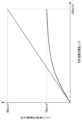
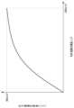
図1は、HDR画像の輝度レンジを出力機器(プリンタ、モニタ)の輝度レンジに圧縮する例を示す図である。図1において、横軸はダイナミックレンジ圧縮(Dレンジ圧縮)を行う入力画像の輝度を表し、縦軸は圧縮後の輝度を表す。最高輝度が1000cd/m2のHDR画像は、実線で示すように、輝度が高い領域のコントラストを小さくすることで出力機器のモニタが使用する100cd/m2前後にDレンジが圧縮される。一方で、例えば高輝度照明下(例えば400cd/m2)で印刷物が展示される場合、HDR画像を、高輝度照明下での観察に適したDレンジに圧縮することが行われる。しかしながら、ICCProfileを用いたソフトプルーフでは、モニタの輝度は、100cd/m2前後に固定されたままであり、CMS間の輝度が一致しないので、高輝度照明下での展示を想定した印刷物のソフトプルーフを行うことができない。FIG. 1 is a diagram showing an example of compressing the luminance range of an HDR image to the luminance range of an output device (printer, monitor). In FIG. 1, the horizontal axis represents the luminance of an input image subjected to dynamic range compression (D range compression), and the vertical axis represents the luminance after compression. As indicated by the solid line, the HDR image with the maximum luminance of 1000 cd/m2 is compressed in the D range to around 100 cd/m2 used by the monitor of the output device by reducing the contrast in the high luminance area. On the other hand, for example, when the print is displayed under high brightness illumination (eg, 400 cd/m2 ), the HDR image is compressed to a D-range suitable for viewing under high brightness illumination. However, in soft-proofing using ICCProfile, the brightness of the monitor remains fixed at around 100 cd/m2 , and the brightness between CMS does not match. cannot be done.
以下で説明する実施形態においては、高輝度照明下での展示用に作成した印刷物を高輝度照明下で観察した状態を、通常100cd/m2前後で使用しているモニタを用いてソフトプルーフ(プレビュー)することを可能にする形態を説明する。In the embodiments described below, soft proofs (soft proofs) are obtained by using a monitor normally used at around 100 cd/m2 for printed materials created for display under high-brightness illumination and observed under high-brightness illumination. (preview).
<<実施形態1>>
<印刷物の展示環境>
図2は、本実施形態で想定している印刷物の展示環境を説明する図である。図2は、部屋200を断面で見た模式図である。天井201には、部屋の照明202が設置されている。壁203には、インクジェットプリンタで出力した印刷物204が飾られている。天井201には、印刷物204を照らす補助照明205が取り付けられている。図2の破線は、補助照明205の光が印刷物204に照射されている様子を表している。補助照明205としては、展示など向けに高輝度な光を照射可能な照明を想定している。このように補助照明205を印刷物204に照射することで、通常100cd/m2前後の輝度よりも高輝度の印刷物(展示物)を観察者が観察することができる。<<
<Exhibition environment for printed materials>
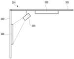
FIG. 2 is a diagram for explaining an exhibition environment for printed matter assumed in this embodiment. FIG. 2 is a schematic cross-sectional view of the
<システム構成>
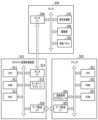
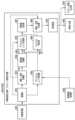
図3は、本実施形態における画像処理装置310を含むシステムの構成を説明するためのブロック図である。本実施形態のシステムは、画像処理装置310と、プリンタ320と、モニタ330とを有する。<System configuration>
FIG. 3 is a block diagram for explaining the configuration of a system including the
画像処理装置310は、ホストPCなどによって構成される。画像処理装置310は、CPU311、RAM312、HDD313、モニタI/F314、キーボード・マウスI/F315、およびデータ転送I/F316を有する。CPU311は、HDD313に保持されるプログラムに従ってRAM312をワークエリアとしながら各種処理を実行する。例えば、CPU311は、キーボード・マウスI/F315を介してユーザから受信したコマンドおよびHDD313に保持されているプログラムに従って、プリンタ320の印刷に用いられる画像データを生成する。そして生成した画像データをデータ転送I/F316を介してプリンタ320に転送する。また、データ転送I/F316を介してプリンタ320から受信した画像データに対し、HDDに記憶されているプログラムに従って所定の処理を行うことができる。モニタI/F314は、キーボード・マウスI/F315を介してユーザから受信したコマンドおよびHDD313に保持されているプログラムに従って、様々な情報をモニタ330に出力する。また、本実施形態では、プリンタ320での印刷に用いられる画像データを用いてモニタ330で画像が表示される。 The
プリンタ320は、CPU321、RAM322、ROM323、画像処理アクセラレータ324、およびデータ転送I/F325を有する。CPU321は、ROM323に保持されるプログラムに従ってRAM322をワークエリアとしながら各種処理を実行する。画像処理アクセラレータ324は、CPU321よりも高速に画像処理を実行可能なハードウェアである。画像処理アクセラレータ324は、CPU321が画像処理に必要なパラメータおよびデータをRAM322の所定のアドレスに書き込むことにより起動され、上記パラメータおよびデータを読み込んだ後、所定の画像処理を実行する。なお、画像処理アクセラレータ324の代わりに同等の処理がCPU321で実行されてもよい。
モニタ330は、信号処理部331、駆動部332、液晶パネル333、およびモニタI/F334を有する。信号処理部331は、モニタI/F334により入力された画像データ(画像信号)および制御データに基づき所定の処理を実行する。駆動部332は、信号処理部331で処理された信号に基づいて液晶パネル333を駆動する。本実施形態のモニタ330は、一般的なモニタディスプレイを用いることができる。信号処理部331は、液晶パネル333の表示に用いられる輝度を調整することができる。本実施形態におけるモニタ330の最大輝度は、400cd/m2であるものとする。なお、一般的な使用態様においては、モニタ330が通常使用する最大輝度は100cd/m2前後に設定されている。The
<画像処理装置のブロック図>
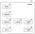
図4は、本実施形態の画像処理装置310の機能ブロックの例を示す図である。画像処理装置310は、画像取得部401、照明輝度取得部402、印刷画像生成部403、印刷出力部404、モニタ輝度変更部405、プレビュー画像生成部406、およびプレビュー画像出力部407を有する。図4に示す各部は、画像処理装置310のCPU311が、HDD313に格納されているプログラムをRAM312に読み出し、実行することで、CPU311が図4に示す各部として機能するものである。<Block Diagram of Image Processing Device>
FIG. 4 is a diagram showing an example of functional blocks of the
本実施形態の画像処理装置310は、高輝度照明下で展示される印刷物を生成するための画像データを生成する装置でもあり、また、高輝度照明下でその印刷物を観察した際の印刷物に対応する画像をプレビューするための画像データを生成する装置でもある。本実施形態では、HDR画像を元にした処理を説明する。 The
画像取得部401は、処理に用いられる画像データを取得する。画像取得部401は、HDD313に保存されている画像データを取得してもよいし、外部の装置などから入力された画像データを取得してもよい。本実施形態では、画像取得部401は、HDR画像の画像データを取得する。HDR画像を説明する。通常のJPEGまたはTIFFのような形式の画像では、画像が有する最大輝度は、100cd/m2である。一方、HDR画像は、画像が有する最大輝度は、1000cd/m2以上とする高輝度の画像情報を持つデータである。本実施形態では、画像取得部401が取得するHDR画像の最大輝度は、1000cd/m2とする。The
照明輝度取得部402は、印刷物が展示される環境の観察条件を取得する。例えば照明輝度取得部402は、ユーザが画像処理装置310に直接入力した照明輝度を取得してもよいし、ユーザが入力した照度を輝度変換し、変換された輝度を取得してもよい。また、展示環境における輝度を不図示の測定器で測定し、測定された輝度が画像処理装置310に入力されてもよい。また、輝度の値を入力させるのではなく、通常照明、中輝度照明、高輝度照明のような選択肢の中からユーザに照明を選択させ、その選択に応じて対応する輝度を取得してもよい。図2に示すように、複数の照明が照射される環境においては、複数の照明を考慮した照明輝度が取得されてもよい。また、ユーザが印刷物を観察する距離を考慮した照明輝度が取得されてもよい。本実施形態では、ユーザが設定した照明輝度、即ち、照明輝度取得部402が取得する照明輝度は、400cd/m2とする。以降の処理は、印刷用の処理とプレビュー表示用の処理とに分かれることになる。まず、印刷用の処理を説明する。The illumination
印刷画像生成部403は、画像取得部401で取得された画像が、照明輝度取得部402で取得された照明輝度の環境での観察に適した印刷物として印刷されるように、印刷用の画像データを生成する。取得されたHDR画像のデータは、最大輝度が1000cd/m2であるので、印刷画像生成部403は、取得された照明輝度の400cd/m2に合わせたDレンジ圧縮を行う。例えば、印刷画像生成部403は、取得されたHDR画像の輝度に対して、1次元ルックアップテーブル(以下、1DLUTという)などを用いて所定の輝度レンジにDレンジ圧縮を行なうことが可能である。The print
図5は、本実施形態で行われるDレンジ圧縮を説明する図である。図5において、横軸はDレンジ圧縮を行う入力の輝度を表し、縦軸は圧縮後の輝度を表す。1000cd/m2の輝度レンジをもつHDR画像データは、図5に示されるような圧縮特性で、プリンタ320で扱うことのできる400cd/m2の輝度レンジに圧縮される。なお、Dレンジ圧縮する際に、暗部も圧縮してしまうと画像全体の雰囲気が変わるので、ここでは暗部の輝度は維持する圧縮が行われている。即ち、暗部の圧縮率よりも明部(特に最大明部)の圧縮率の方が高くなるように圧縮が行われている。コントラストを重視する場合には、暗部も含めてDレンジ圧縮してもよい。なお、この例では1DLUTでDレンジ圧縮する形態を説明したが、Dレンジ圧縮する方法は、任意の方法でよい。印刷画像生成部403は、印刷用の画像データを生成するので、印刷データ生成に特有のガマット圧縮などの処理が行われてもよい。FIG. 5 is a diagram for explaining the D-range compression performed in this embodiment. In FIG. 5, the horizontal axis represents the luminance of the input subjected to D-range compression, and the vertical axis represents the luminance after compression. HDR image data with a luminance range of 1000 cd/m2 is compressed to a luminance range of 400 cd/m2 that can be handled by
印刷出力部404は、印刷画像生成部403によって生成された印刷用の画像データをプリンタ320に出力する。プリンタ320では、印刷出力部404から出力された画像データを用いた印刷処理が行われる。この結果得られた印刷物は、図2に示すように照明輝度の環境下で展示され、観察者は、400cd/m2の輝度レンジで印刷物を観察することができる。The
次に、プレビュー表示用の処理を説明する。モニタ輝度変更部405は、照明輝度取得部402において取得した輝度照明に応じた輝度に、モニタ330の輝度を変更する。例えば、その取得した輝度照明の下で印刷物の白を見た場合と同じくらいの明るさになる輝度に、モニタの輝度を設定する。モニタ輝度変更部405は、モニタI/F314を介してモニタ330に輝度変更信号を出力する。本実施形態では、モニタ輝度変更部405は、モニタ輝度を400cd/m2に変更する指示を示す信号をモニタ330に出力する。この指示を受けて、モニタ330は、最大輝度を400cd/m2に設定する。Next, processing for preview display will be described. A monitor
プレビュー画像生成部406は、プレビュー用の画像を生成する。プレビュー画像生成部406は、印刷画像生成部403と同様に、Dレンジ圧縮を行う。即ち、最大輝度が1000cd/m2であるHDR画像のデータを、最大輝度が観察環境の照明輝度の400cd/m2の画像データとなるように、Dレンジ圧縮を行う。なお、Dレンジ圧縮は、印刷画像生成部403で説明した画像処理と同様に行うことが可能である。プレビュー画像生成部406は、モニタでのプレビュー用の画像データを生成するので、モニタ表示に特有の画像処理を行ってもよい。A preview
プレビュー画像出力部407は、プレビュー画像生成部406で生成されたプレビュー画像をモニタ330に出力する。モニタ330は、モニタ輝度変更部405で輝度が変更されている状態で、プレビュー画像出力部407から出力されたプレビュー画像を表示する。 A preview
以上の処理によれば、印刷出力部404によって印刷された印刷物を照明輝度400cd/m2の展示環境で展示した場合の見た目と、プレビュー画像出力部407によってモニタ330に表示されているプレビュー画像の見た目とは、近い印象になる。つまり、モニタ輝度変更部405で輝度変更されたモニタ330上にプレビュー画像出力部407によってプレビュー画像を表示することで、実際の展示環境で印刷物を観察した場合の印刷物の画像を確認することができる。即ち、通常の輝度条件(100cd/m2前後)と異なる輝度条件においても、ソフトプルーフを実現することができる。According to the above processing, the appearance of printed matter printed by the
なお、図4の構成では、ソフトプルーフを説明するために、印刷画像とプレビュー画像との両方が生成される構成を説明したが、印刷画像を生成する処理は、ユーザがプレビュー画像を確認した後に行われてよい。つまり、画像処理装置310は、印刷出力部404によって印刷指示がプリンタ320で行われる前に、プレビュー画像出力部407によってモニタ330に表示をさせ、ユーザによる画像の確認を待つ。そして、印刷出力部404は、印刷する指示がユーザから入力された場合のみ、印刷出力部404から印刷指示をプリンタ320に出力してもよい。 In the configuration of FIG. 4, the configuration in which both the print image and the preview image are generated has been described in order to explain the soft proof. may be done. That is, the
また、図3で説明したシステム構成は、概略を示したものであり、画像処理装置310、プリンタ320、およびモニタ330は、ネットワークを通じて接続されていてもよい。例えば、画像処理装置310およびモニタ330が、第一の拠点に設置され、プリンタ320が、第一の拠点と異なる第二の拠点に設置されてもよい。そして、モニタ330で、ソフトプルーフを行い、その後、遠隔地に設置されている実際の展示場近くの第二の拠点においてプリンタ320による印刷が行われてもよい。 Also, the system configuration described with reference to FIG. 3 is a schematic, and the
図6は、Dレンジ圧縮を行った効果を説明する図である。図6(a)の画像601は、画像取得部401で取得された画像(入力画像)を示す図である。画像601は、HDR画像である。領域602は、太陽を表しており、画像601において最も明るい部分であり、輝度は1000cd/m2である。領域603は、空の部分であり、輝度は500cd/m2である。領域604は、山の陰になっている部分であり、輝度は18cd/m2である。FIG. 6 is a diagram for explaining the effect of performing D-range compression. An
図6(b)は、画像601に対応する画像605を示す。画像605は、画像601をDレンジ圧縮して印刷した印刷物を照明輝度400cd/m2下で見た場合の見た目を表したものである。照明輝度400cd/m2であるので、画像605の最も明るい部分の領域606の輝度は、400cd/m2となる。領域607の輝度は、Dレンジ圧縮されて300cd/m2になる。領域608の輝度は、図5に示すように暗部の輝度が維持されるDレンジ圧縮を行うことから、18cd/m2のままとなっている。先に説明したように、プレビュー画像出力部407によって出力される画像を、輝度が変更されたモニタ330上で表示することで、図6(b)と同様の表示をすることができる。先に説明したように、本実施形態のモニタ330は、最大輝度が400cd/m2であるので、領域606は、印刷物の展示環境と同様に、400cd/m2の輝度でモニタ330上にプレビュー表示がされることになる。なお、モニタ330では、画像を表示する領域とそれ以外の領域とで、輝度を異ならせて表示してもよい。例えば、最大輝度を400cd/m2に上げたモニタ330は、一般的な観察には眩しくなる。このため、画像を表示する領域以外のUI表示については、モニタ330の輝度を上げた場合、暗く表示するようにモニタ330を制御してもよい。図6(c)は、後述する実施形態3にて説明する。FIG. 6B shows an
なお、上記の説明では、モニタ330の輝度を、照明輝度取得部402で取得した照明輝度と同じ輝度に変更する例を説明したが、モニタ330の輝度を、取得した照明輝度に完全に一致させることができない場合がある。本実施形態は、変更されるモニタの輝度が、照明輝度取得部402で取得した照明輝度と同じ輝度に一致していなくてもよい。変更されるモニタの輝度と、照明輝度取得部402で取得した照明輝度との差が、所定の範囲内であれば、実質的に同等の視覚効果を得ることができるからである。以下、説明する。 In the above description, an example in which the brightness of the
現状使われているソフトプルーフでは、入力画像の最大輝度100cd/m2に対してモニタの輝度は80cd/m2から120cd/m2の範囲で使われている。この範囲は、おおむね人間が同等の視覚効果を許容できる輝度の範囲と考えることができる。人間の視覚特性を考慮した明るさの単位としてPQ(Perceptual Quantization)カーブが広く用いられている。In the currently used soft proof, the maximum luminance of the input image is 100 cd/m2 and the luminance of the monitor is in the range of 80 cd/m2 to 120 cd/m2 . This range can be roughly considered as the range of luminance within which humans can tolerate an equivalent visual effect. A PQ (Perceptual Quantization) curve is widely used as a unit of brightness in consideration of human visual characteristics.
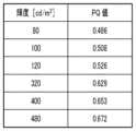
図7は、輝度とPQ値との対応表を示す図である。図7に示すように、輝度80cd/m2は、PQ値0.486に対応する。同様に、輝度100cd/m2=PQ値0.508、輝度120cd/m2=PQ値0.526である。このため、PQ値でプラスマイナス0.02前後がソフトプルーフで実用になる輝度と考えられる。FIG. 7 is a diagram showing a correspondence table between luminance and PQ value. As shown in FIG. 7, a luminance of 80 cd/m2 corresponds to a PQ value of 0.486. Similarly,
一方、輝度400cd/m2前後では、図7に示すように、輝度320cd/m2=PQ値0.629、輝度400cd/m2=PQ値0.653、輝度480cd/m2=PQ値0.672である。PQ値でプラスマイナス0.02前後がソフトプルーフで実用になる輝度と想定すると、照明輝度が400cd/m2の場合、モニタ輝度の範囲を320cd/m2~480cd/m2とすることで、人間が同等の視覚効果を許容できる。つまり、照明輝度取得部402で取得した照明輝度が400cd/m2の場合、モニタ輝度を320cd/m2~480cd/m2の範囲において設定することができ、この範囲において同等のソフトプルーフの効果を得ることができる。On the other hand, when the luminance is around 400 cd/m2 , as shown in FIG. 7,
<フローチャート>
図8は、本実施形態の画像処理装置310のフローチャートの一例を示す図である。図8のフローチャートで示される一連の処理は、CPU311がHDD313に記憶されているプログラムコードをRAM312に展開し実行することにより行われる。あるいはまた、図8におけるステップの一部または全部の機能をASICや電子回路等のハードウェアで実現してもよい。なお、各処理の説明における記号「S」は、当該フローチャートにおけるステップであることを意味する。<Flowchart>
FIG. 8 is a diagram showing an example of a flowchart of the
S801において画像取得部401は、印刷物の元データとなるHDR画像のデータを取得する。S802において照明輝度取得部402は、印刷物が展示される観察環境下の照明輝度を取得する。S801とS802とは、逆の順序でもよい。 In step S<b>801 , the
S803でモニタ輝度変更部405は、モニタ330の輝度をS802で取得された照明輝度に応じて変更する。S804でプレビュー画像生成部406は、S801で取得されたHDR画像のデータを、S802で取得された照明輝度のDレンジに適合するように、Dレンジ圧縮を行う。即ち、プレビュー画像生成部406は、S803で変更されたモニタ輝度のDレンジに適合するように、Dレンジ圧縮を行い、プレビュー画像を生成する。S805でプレビュー画像出力部407は、S804で生成したプレビュー画像のデータをモニタ330に出力する。これにより、モニタ330にて、観察環境下での展示環境と同等の状況でプレビュー画像が表示される。 In S803, the monitor
S806において画像処理装置310は、ユーザから印刷指示が入力されたかを判定する。印刷指示が入力された場合、S807に進み、そうでない場合、S809に進む。S807において印刷画像生成部403は、S801で取得されたHDR画像のデータを、S802で取得した照明輝度のDレンジに適合するようにDレンジ圧縮を行い、印刷画像を生成する。そして、S808で印刷出力部404は、S807で生成された印刷画像のデータをプリンタ320に出力し、処理を終了する。これにより、プリンタ320にて、印刷物が作成される。この作成された印刷物を実際の観察環境にて展示することで、Dレンジが拡張された印刷物が観察される。 In S806, the
S806でユーザから印刷指示が入力されない場合、画像処理装置310は、S809でユーザから校正指示が入力されたかを判定する。ソフトプルーフでは、モニタ330上で印刷物の確認を行うことができ、必要に応じて画像の修正が行われる。校正指示がない場合には、処理を終了する。校正指示がある場合、S810に進み、校正処理が行われる。その後、S804に進み、プレビュー画像生成部406は、校正処理が行われた画像データを用いてプレビュー画像を生成する。なお、S807で印刷画像生成部403は、S810で画像データが校正されている場合、校正後の画像データを用いて印刷処理を行う。 If the user does not input a print instruction in S806, the
<Dレンジ圧縮の詳細>
図9は、Dレンジ圧縮を行う印刷画像生成部403およびプレビュー画像生成部406の詳細を示すブロック図である。現像部901は、画像取得部401で取得された画像のデータを所定の形式の画像データに変換する。現像部901では、画像取得部401で取得された画像のDレンジも導出される。求められたDレンジの値は、ダイナミックレンジ取得部902へと送られる。ダイナミックレンジ取得部902は、画像取得部401で取得された入力となる画像のDレンジと、照明輝度取得部402で取得された出力となる輝度情報(Dレンジ)とをそれぞれ取得し、ダイナミックレンジ圧縮部905へと出力する。なお、本実施形態では、Dレンジにおいて暗部は、「0」で固定しているので、明部の最大輝度がDレンジに対応することになる。<Details of D range compression>
FIG. 9 is a block diagram showing details of the print
輝度色差分離部903は、現像された画像を輝度と色差とに分離する。周波数分離部904は、画像を空間周波数の低周波成分と高周波成分とに分離する。ここでは、輝度を低周波成分と高周波成分とに分離する処理が行われる。分離された周波数のうち、低周波成分は、ダイナミックレンジ圧縮部905に出力される。ダイナミックレンジ圧縮部905は、ダイナミックレンジ取得部902で取得したDレンジの値に基づき処理を実施する。このとき、現像部901からのデータを利用して処理が行われる。 A luminance and color
一方、高周波成分は、コントラスト補正部906に出力される。コントラスト補正部906は、コントラスト補正を行う。このように、周波数成分毎に処理が行われた後、周波数合成部907は、分離されている周波数成分を合成する。輝度色差合成部908は、周波数合成部907で合成された輝度と、色差とを合成する。このような処理により、Dレンジ圧縮が行われる。なお、色処理部909では、出力デバイス(プリンタまたはモニタ)に応じた色変換処理が行われる。 On the other hand, high frequency components are output to the
なお、上記で説明したように、印刷画像生成部403およびプレビュー画像生成部406の処理は、共通化した処理とすることができる。本実施形態では、印刷画像生成部403およびプレビュー画像生成部406を別個に備えている形態を説明したが、両者を統合した画像生成部を備える構成としてもよい。 As described above, the processing of the print
図10は、印刷画像生成部403およびプレビュー画像生成部406の処理を含むフローチャートである。S1001で画像取得部401は、撮像された画像データを取得する。ここで取得する画像データは、デジタルカメラで撮影し、処理されたJPEG形式などの汎用的なデータではなく、撮像されたままのいわゆるRAWデータである。画像処理によってDレンジを拡大するからである。S1002で現像部901は、RAWデータの現像を行う。 FIG. 10 is a flowchart including processing of the print
S1003でダイナミックレンジ取得部902は、入力の明暗部の輝度データを取得する。明部については、取得した画像データに記載されているカメラ情報および撮影時設定から導出される値と、S1002の現像処理の結果とから求めることができる。特に明部は、ホワイトバランス調整により輝度データの取得が行われる。なお、ホワイトバランス調整の際、飽和レベルおよび画素情報に応じた置換処理を実施することで、階調が得られていない高輝度領域の階調を拡張(N段:N≧1)することが可能である。暗部は、値が0として設定される。なお、黒濃度が表せない紙では、その紙の黒濃度を暗部の輝度データとして入力してもよい。また、入力の黒と、出力の黒とが一致しない場合は、一致させるようにLUT変換してもよい。S1004でダイナミックレンジ取得部902は、出力側の明暗部の輝度データを取得する。 In S1003, the dynamic
S1005で輝度色差分離部903は、RGBの信号値から、輝度(Y)と色差(CbCr)との情報に分離を行う。変換は、以下の式により実施される。
Y=0.299×R+0.587×G+0.114×B
Cb=-0.16874×R-0.33126×G+0.5×B 式(1)
Cr=0.5×R-0.41869×G-0.081×BIn S1005, the luminance/color
Y=0.299×R+0.587×G+0.114×B
Cb = -0.16874 x R - 0.33126 x G + 0.5 x B formula (1)
Cr=0.5×R−0.41869×G−0.081×B
S1006で周波数分離部904は、輝度に変換された画像を、低周波成分画像と高周波成分画像とに分離する。低周波成分を生成するためには、ローパスフィルタを適用する。処理方法は、空間フィルタを適用してもよいし、一旦、FFTにより空間周波数に変換し、フィルタ処理後にIFFTで戻してもよい。対象とする周波数は、印刷物を鑑賞する際の用紙サイズ、観察距離から、人間の視覚特性を考慮し、決定すればよい。高周波成分は、逆のハイパスフィルタを適用することで取得してもよいし、得られた低周波成分を元の画像から除算することで取得してもよい。 In S1006, the frequency separation unit 904 separates the image converted into luminance into a low frequency component image and a high frequency component image. A low pass filter is applied to generate the low frequency components. As a processing method, a spatial filter may be applied, or a spatial frequency may be converted once by FFT, and then returned by IFFT after filtering. The target frequency may be determined in consideration of the human visual characteristics from the paper size and observation distance when viewing printed matter. High-frequency components may be obtained by applying an inverse high-pass filter, or by dividing the resulting low-frequency components from the original image.
S1007でダイナミックレンジ圧縮部905は、S1003で取得された入力およびS1004で取得された出力の明暗部の情報に基づき、低周波成分に対し、Dレンジ圧縮処理を実施する。S1008でコントラスト補正部906は、高周波成分に対し、コントラスト補正処理を実施する。コントラスト補正処理は、例えば得られた画像に対し、係数kを乗じる処理である。より、撮影時のシーンに近づける場合はk=1付近とし、さらに印刷物のインクの滲みなどの劣化を考慮したい場合は、1以上の値をkに設定すればよい。S1007とS1008とは、逆の順序で行われてもよいし、並行して行われてもよい。 In S1007, the dynamic
S1009で周波数合成部907は、低周波成分でのDレンジ圧縮された低周波成分画像と、高周波成分でのコントラスト補正された高周波成分画像との合成を行う。これにより、所定のDレンジに圧縮され、コントラストの補正された輝度画像が得られる。 In S1009, the
S1010で輝度色差合成部908は、色差成分を合成し、下記式でRGBに変換する。
R=Y+1.402×Cr
G=Y-0.34414×Cr-0.71414×Cr 式(2)
B=Y+1.772×CbIn S1010, the luminance/color
R=Y+1.402×Cr
G=Y-0.34414×Cr-0.71414×Cr Formula (2)
B=Y+1.772×Cb
S1011で色処理部909は、得られたRGB信号値に対し、印刷のための画像処理またはプレビューのための画像処理を行う。 In S1011, the
以上説明したように、本実施形態によれば、高輝度照明下の展示用に作成する印刷物と同様の見え方を、モニタ330上で実現することができる。このため、高輝度照明下の展示用に作成する印刷物のソフトプルーフを実現することができる。 As described above, according to the present embodiment, it is possible to realize on the
<<実施形態2>>
実施形態1では、Dレンジを、一般的にICCProfileなどを用いて行われるレンジよりも広い(輝度が高い)レンジとなるように、HDR画像をDレンジ圧縮して、その高輝度に対応した画像データをプリンタおよびモニタに出力する形態を説明した。本実施形態では、一般的なプリンタおよびSDR(Standard Dynamic Range)モニタに適したデータを出力する形態を説明する。<<Embodiment 2>>
In the first embodiment, the HDR image is D-range-compressed so that the D-range is wider (brighter) than the range generally performed using ICCProfile and the like, and an image corresponding to the high brightness is obtained. A form of outputting data to a printer and a monitor has been described. In this embodiment, a mode of outputting data suitable for a general printer and an SDR (Standard Dynamic Range) monitor will be described.
図11は、本実施形態における画像処理装置310のブロック図である。図4と同様の構成については同一の符号を付し説明を省略する。本実施形態では、実施形態1の印刷画像生成部403およびプレビュー画像生成部406の代わりに、両者を統合した画像生成部1103を備えている。また、輝度正規化部1110をさらに備えている。印刷出力部1104およびプレビュー画像出力部1107は、輝度正規化部1110から出力されたデータに基づく処理を行うように構成されている。 FIG. 11 is a block diagram of the
本実施形態では、実施形態1と同様に、画像取得部401で取得されるHDR画像の最大輝度は、1000cd/m2とする。また、照明輝度取得部402で取得される照明輝度も、実施形態1と同様に、400cd/m2とする。In this embodiment, as in the first embodiment, the maximum brightness of the HDR image acquired by the
画像生成部1103では、印刷用かつプレビュー用の画像を生成する。実施形態1で説明したように、取得されたHDR画像のデータは、最大輝度が1000cd/m2であるので、印刷画像生成部403は、取得された照明輝度の400cd/m2に合わせたダイナミックレンジ圧縮を行う。Dレンジ圧縮は、実施形態1で説明した通りである。An
輝度正規化部1110は、画像生成部1103で生成された、Dレンジ圧縮された画像の正規化を行う。画像生成部1103では、最大輝度400cd/m2の画像を生成している。ここで、通常のプリンタやSDRモニタでは、最大輝度400cd/m2のデータを入力できない。このため、本実施形態では、輝度正規化部1110において、輝度0cd/m2の色をRGB=0、輝度400cd/m2の色をRGB=255になるように、画像全体の正規化を行う。つまり、通常のプリンタやSDRモニタで用いられている単位輝度となるように画像全体の正規化を行う。A
印刷出力部1104は、輝度正規化部1110によって正規化された画像データを用いてプリンタ320に印刷出力を行わせる。正規化された画像を印刷するので、印刷された印刷物を観察照明輝度が400cd/m2の照明光の下で観察すると400cd/m2に最適化された印刷物を観察することができる。A
プレビュー画像出力部1107は、画像生成部1103で生成された画像のプレビューを行う。通常のモニタもRGBデータを入力とする。モニタ輝度変更部405では、モニタ330の使用する最大輝度は400cd/m2に輝度変更されているので、RGB=255のデータは400cd/m2の画像として表示されることとなる。A preview
以上説明したように、本実施形態では、輝度正規化部1110で輝度の正規化を行うことにより、通常のプリンタ・SDRモニタに対しても圧縮後のデータを入力でき、印刷およびプレビューをすることができる。また、印刷用およびプレビュー用とで圧縮の処理を共通化できる。 As described above, in this embodiment, by normalizing the luminance in the
<<実施形態3>>
本実施形態は、モニタの輝度を変更せず、通常のモニタ輝度(100cd/m2前後)でプレビューを行う形態を説明する。実施形態2では、モニタ輝度変更部405が、照明輝度取得部402において取得された照明輝度に合わせてモニタ330の輝度を変更する例を説明した。ここで、モニタ330の輝度を照明輝度に変更せず、通常のモニタの輝度(100cd/m2前後)のままとし、輝度正規化部1110で正規化された正規化画像をモニタ330上に表示する。この場合、印刷出力部1104によって印刷された印刷物を通常照明(100cd/m2前後)で見た場合の見た目をモニタ上でプレビューすることができる。印刷物は、高輝度照明用に作成されるものであるが、通常照明下での見え方をプレビュー上で確認したいユースケースがあり、本実施形態は、そのような場合に有用である。<<Embodiment 3>>
In this embodiment, a preview is performed with normal monitor luminance (approximately 100 cd/m2 ) without changing the luminance of the monitor. In the second embodiment, an example has been described in which the monitor
図6を用いて説明する。図6(b)では、画像605は、印刷物を照明輝度400cd/m2下で見た場合の見た目を表したものであることを説明した。図6(c)を用いて高輝度照明用の印刷物を通常照明(100cd/m2前後)で見た場合の見た目について説明する。画像609は、図6(b)に相当する印刷物を照明輝度100cd/m2下で見た場合の見た目を表したものである。照明輝度100cd/m2のため、画像の最も明るい部分の領域610は、輝度100cd/m2となる。全体として暗くなるため、領域611は、輝度75cd/m2になり、領域612は、輝度13.5cd/m2となっている。モニタの輝度を100cd/m2でプレビューを行うことにより、モニタにおいても同様の状態をプレビュー表示できる。Description will be made with reference to FIG. It has been explained that the
本実施形態で画像処理装置310は、通常照明用プレビューモードと、観察環境照明用プレビューモードとの2つのプレビューモードを設定可能に構成されている。これらのモードは、ユーザ指示によって切り替え可能である。通常照明用プレビューモードの場合、モニタ輝度変更部405は、モニタ330の輝度を通常輝度にする。観察環境照明用プレビューモードの場合、モニタ輝度変更部405は、モニタ330の輝度を観察照明輝度と同じ輝度に設定し、正規化されたデータをモニタに表示する。このように、プレビュー画像を表示している状態において、モニタ330の輝度を切り替えることにより、通常の照明輝度で展示した場合と、高輝度照明の照明輝度で展示した場合とを比較することが可能である。このため、モニタ330上において、高輝度照明向けの印刷の効果をより認識しやすくなる。 In this embodiment, the
<<実施形態4>>
本実施形態は、モニタ330の輝度の変更タイミングに関する形態である。上述した実施形態では、印刷物が展示される展示環境の照明輝度は、通常輝度に比べて高輝度な照明を想定している。モニタ330においても高輝度な照明のプレビュー画像を表示することになるので、モニタ輝度も高輝度となる。高輝度なモニタを見続けると、目の疲労など、各種の影響が想定される。このため、本実施形態では、高輝度照明プレビューを行う場合のみ、モニタ330の輝度を変更し、高輝度プレビューが終了したらモニタ330の輝度を戻す処理を行う。即ち、ユーザから高輝度プレビューのモードを解除する指示が入力された場合、モニタ330の輝度を戻す処理を行う。あるいは、印刷指示の入力があった場合、モニタ330の輝度を戻す処理を行ってもよい。また、所定のタイマーを設定し、所定期間の高輝度プレビューが経過した時点で、輝度を元に戻す処理を行ってもよい。このように、高輝度照明プレビューのときのみ輝度を変更し、終了したら輝度を戻すことで、ユーザの目の疲れ等を軽減することができる。モニタ330の輝度を戻す場合、モニタ輝度変更部405は、高輝度に変更する前の輝度を記憶しておき、変更前の輝度に戻す指示をモニタ330に出力してもよい。あるいは、変更前の輝度まで、段階的に輝度を下げる制御が行われてもよい。<<Embodiment 4>>
This embodiment relates to the change timing of the brightness of the
<<実施形態5>>
これまでの実施形態では、プレビュー表示が切り替えられる例を説明した。本実施形態は、通常照明でプレビューした結果と高輝度照明でプレビューした結果とを両方並べて表示する形態である。<<Embodiment 5>>
In the embodiments so far, an example in which the preview display is switched has been described. In this embodiment, the result of previewing under normal illumination and the result of previewing under high-intensity illumination are both displayed side by side.
並べて表示することで、通常の照明輝度で展示した場合と、高輝度照明の照明輝度に同時に比較することが可能で、高輝度照明向けの印刷の効果をより認識することができる。なお、1つのモニタ330上の表示領域を複数の領域に分割し、領域ごとに輝度を切り替えられる場合、1つのモニタ330上で画像を並べて表示してよい。あるいは、複数のモニタ330を備えたシステムとしてもよく、通常照明用のモニタと高輝度照明用のモニタとを並べてもよい。 By displaying them side by side, it is possible to simultaneously compare the display under normal lighting and the display under high-brightness lighting. Note that if the display area on one
<<実施形態6>>
これまでの実施形態では、モニタ330の使用可能な最大輝度が400cd/m2である例を説明した。ここで、通常のモニタは、100cd/m2前後の輝度で使われることを想定されている。このため、モニタの種類によっては、実施形態1のように観察環境の照明輝度400cd/m2を想定した場合、モニタの輝度を同程度(即ち、320~480cd/m2前後)に上げられないことがある。<<Embodiment 6>>
In the embodiments so far, an example has been described in which the maximum usable brightness of the
本実施形態では、必ずしも観察環境の照明輝度と同程度の輝度を出力できないモニタを用いる場合にも、通常の使用される輝度(100cd/m2前後)よりも、輝度を上げる。どのようなモニタであっても輝度調整は可能である。現在使用している輝度に対して、その輝度よりも高い輝度が観察照明輝度として指定された場合、少しでも輝度を上げた方が、見た目の一致度が近づくことになる。このように、モニタの輝度を観察照明輝度のレベルまで上げられない場合であっても、モニタ輝度を通常よりも上げることで、プレビュー時の視覚効果をより近づけることができる。In the present embodiment, even when using a monitor that cannot necessarily output the same level of brightness as the illumination brightness of the viewing environment, the brightness is increased above the brightness normally used (around 100 cd/m2 ). Brightness can be adjusted on any monitor. If a brightness higher than the currently used brightness is specified as the observation illumination brightness, increasing the brightness even a little will bring the degree of matching in appearance closer. In this way, even if the monitor luminance cannot be increased to the level of the viewing illumination luminance, the visual effect at the time of preview can be brought closer by increasing the monitor luminance above normal.
<<実施形態7>>
上述した実施形態では、画像取得部401で取得する画像がHDR画像である形態を説明した。本実施形態では、画像取得部401で取得する画像が通常の標準ダイナミックレンジ画像(SDR画像)である形態を説明する。<<Embodiment 7>>
In the above-described embodiment, the image obtained by the
Dレンジを圧縮するだけではなく、Dレンジを拡張する技術も広く知られている。上述した実施形態において、印刷画像生成部403、プレビュー画像生成部406、および画像生成部1103が、Dレンジ圧縮ではなく、Dレンジ拡張処理を行い、印刷画像およびプレビュー画像を生成する形態としてもよい。本実施形態によれば、入力画像がHDR画像でなく、SDR画像であっても、Dレンジ拡張することで高輝度照明に適した印刷が可能であり、かつプレビューも可能となる。 Techniques for expanding the D-range as well as compressing the D-range are widely known. In the above-described embodiment, the print
<<その他の実施形態>>
上記の実施形態では、画像処理装置310は、モニタ330用の画像を生成するとともに、モニタ330の輝度を変更可能な形態を説明したが、これらを別々の装置で実現してもよい。例えば、観察環境の照明輝度の取得に応じて、モニタ330の輝度を変更する制御を行う表示制御装置を設け、画像処理装置310は、観察環境の照明輝度に応じたモニタ330用の画像を生成してモニタ330に出力する形態でもよい。即ち、画像処理装置310がモニタ330の輝度を変更せず、他の装置がモニタ330の輝度を変更する形態でもよい。<<other embodiments>>
In the above embodiment, the
本発明は、上述の実施形態の1以上の機能を実現するプログラムを、ネットワーク又は記憶媒体を介してシステム又は装置に供給し、そのシステム又は装置のコンピュータにおける1つ以上のプロセッサがプログラムを読出し実行する処理でも実現可能である。また、1以上の機能を実現する回路(例えば、ASIC)によっても実現可能である。 The present invention supplies a program that implements one or more functions of the above-described embodiments to a system or apparatus via a network or a storage medium, and one or more processors in the computer of the system or apparatus reads and executes the program. It can also be realized by processing to It can also be implemented by a circuit (for example, ASIC) that implements one or more functions.
401 画像取得部
402 照明輝度取得部
405 モニタ輝度変更部
406 プレビュー画像生成部401
Claims (25)
Translated fromJapanese画像データを取得する第一取得手段と、
前記所定の観察環境の照明輝度を取得する第二取得手段と、
前記第二取得手段で取得した照明輝度に応じて前記表示装置の輝度を変更する変更手段と、
前記第一取得手段で取得した画像データの輝度のレンジに対応するPQ値と、前記第二取得手段で取得した照明輝度のレンジに対応するPQ値との差が、所定の範囲内となるように、前記画像データを変換する変換手段と、
前記変換手段で変換された画像データを前記変更手段で輝度が変更された前記表示装置に出力する出力手段と、
を有することを特徴とする画像処理装置。An image processing device forpreviewinga statein which a printed matter printed based on image data is viewedunder a predetermined viewing environment on a display device,
a first acquisition means for acquiring image data;
a second acquiring means for acquiring the illumination luminance of the predetermined viewing environment;
changing means for changing the brightness of the display device according to the illumination brightness acquired by the second acquiring means;
The difference betweenthe PQ value corresponding to the luminance range of the image data acquired by the first acquisition means and thePQ value corresponding to the illumination luminance range acquired by the second acquisition means is within a predetermined range. a converting means for convertingthe image data ;
output means for outputting the image data converted by the conversion means to the display device whose luminance has been changed by the change means;
An image processing device comprising:
前記変換手段は、前記第一取得手段で取得した画像データの輝度のレンジを圧縮する変換を行うことを特徴とする請求項1または2に記載の画像処理装置。The image data acquired by the first acquisition means is RAW data,
3. The image processing apparatus according to claim1 , wherein said conversion means performs conversion for compressing a luminance range of the image data acquired by said first acquisition means.
前記変換手段は、前記第一取得手段で取得した画像データの輝度のレンジを拡張する変換を行うことを特徴とする請求項1または2に記載の画像処理装置。The image data acquired by the first acquisition means is SDR image data,
3. The image processing apparatus according to claim1 , wherein said conversion means performs conversion to extend a luminance range of the image data acquired by said first acquisition means.
前記出力手段は、前記正規化された画像データを前記表示装置に出力することを特徴とする請求項1から6のいずれか一項に記載の画像処理装置。The conversion means normalizes the converted image data according to the unit brightness used in the display device,
7. The image processing apparatus according to claim 1, wherein said output means outputs said normalized image data to said display device.
前記表示装置の輝度を第1モードと第2モードとに切り替え可能であり、
前記第1モードの場合、前記表示装置の輝度を、前記第二取得手段で取得した照明輝度に応じて変更し、
前記第2モードの場合、前記表示装置の輝度を、標準光源の輝度に変更することを特徴とする請求項7に記載の画像処理装置。The changing means is
The brightness of the display device can be switched between a first mode and a second mode,
In the case of the first mode, changing the brightness of the display device according to the illumination brightness acquired by the second acquisition means,
8. The image processing apparatus according to claim7 , wherein, in the case of the second mode, the brightness of the display device is changed to the brightness of a standard light source.
前記変更手段は、第1領域のみの輝度を前記第二取得手段で取得した照明輝度に応じて変更し、
前記出力手段は、前記表示装置の前記第1領域および前記第1領域と異なる第2領域のいずれにも前記正規化された画像データを表示させる指示を出力することを特徴とする請求項7に記載の画像処理装置。The display device is capable of adjusting luminance for each region,
The changing means changes the brightness of only the first region according to the illumination brightness acquired by the second acquiring means,
8. The apparatus according to claim7 , wherein said output means outputs an instruction to display said normalized image data in both said first area and a second area different from said first area of said display device. The described image processing device.
第1表示装置および第2表示装置の輝度をそれぞれ変更することが可能であり、
前記第1表示装置のみの輝度を前記第二取得手段で取得した照明輝度に応じて変更し、
前記出力手段は、前記第1表示装置および前記第2表示装置のいずれにも前記正規化された画像データを出力することを特徴とする請求項7に記載の画像処理装置。The changing means is
It is possible to change the brightness of the first display device and the second display device, respectively;
changing the brightness of only the first display device according to the illumination brightness acquired by the second acquisition means;
8. The image processing apparatus according to claim7 , wherein said output means outputs said normalized image data to both said first display device and said second display device.
前記変換手段は、前記第三取得手段で取得した情報に応じて変換することを特徴とする請求項1から15のいずれか一項に記載の画像処理装置。 16. The image processing apparatus according to any one of claims 1 to 15, wherein the converting means converts according to the information acquired by the third acquiring means.
前記所定の観察環境の照明輝度を取得する取得手段と、
前記取得手段で取得した照明輝度に応じて前記表示装置の輝度を変更する変更手段と、
前記画像データの輝度のレンジに対応するPQ値と、前記取得手段が取得した照明輝度のレンジに対応するPQ値との差が、所定の範囲内となるように、前記画像データを変換する変換手段と、
を有することを特徴とする制御装置。A control device for controlling a display device forpreviewinga statein which printed matter printed based on image data is viewedunder a predetermined viewing environment,
acquisition means for acquiring the illumination luminance of the predetermined viewing environment;
changing means for changing the brightness of the display device according to the illumination brightness acquired by the acquiring means;
Conversion for converting the image data such that the difference between the PQ value corresponding to the luminance range of the image data and the PQ value corresponding to the illumination luminance range acquired by the acquisition means is within a predetermined range. means and
A control device comprising:
画像データを取得する第一取得ステップと、
前記所定の観察環境の照明輝度を取得する第二取得ステップと、
前記第二取得ステップで取得した照明輝度に応じて前記表示装置の輝度を変更する変更ステップと、
前記第一取得ステップで取得した画像データの輝度のレンジに対応するPQ値と前記第二取得ステップで取得した照明輝度のレンジに対応するPQ値との差が、所定の範囲内となるように、前記画像データを変換する変換ステップと、
前記変換ステップで変換された画像データを前記変更ステップで輝度が変更された前記表示装置に表示させる出力ステップと、
を有することを特徴とする画像処理方法。An image processing method forpreviewing on a display devicea statein which printed matter printed based on image data is viewedunder a predetermined viewing environment, comprising:
a first acquisition step of acquiring image data;
a second acquisition step of acquiring the illumination luminance of the predetermined viewing environment;
a changing step of changing the brightness of the display device according to the illumination brightness acquired in the second acquiring step;
The difference betweenthe PQ value corresponding to the luminance range of the image data obtained in the first obtaining step and thePQ value corresponding to the illumination luminance range obtained in the second obtaining step is within a predetermined range. , a transforming step of transforming the image data ;
an output step of displaying the image data converted in the converting step on the display device whose luminance has been changed in the changing step;
An image processing method characterized by comprising:
前記所定の観察環境の照明輝度を取得する取得ステップと、
前記取得ステップで取得した照明輝度に応じて前記表示装置の輝度を変更する変更ステップと、
前記画像データの輝度のレンジに対応するPQ値と、前記取得ステップが取得した照明輝度のレンジに対応するPQ値との差が、所定の範囲内となるように、前記画像データを変換する変換ステップと、
を有することを特徴とする制御方法。A control method for controlling a display device forpreviewinga statein which printed matter printed based on image data is viewedunder a predetermined viewing environment, comprising:
an acquisition step of acquiring the illumination luminance of the predetermined viewing environment;
a changing step of changing the brightness of the display device according to the illumination brightness acquired in the acquiring step;
Transformation for converting the image data such that a difference between a PQ value corresponding to the luminance range of the image data and a PQ value corresponding to the illumination luminance range obtained in the obtaining step is within a predetermined range. a step;
A control method characterized by having
画像データを取得する第一取得手段と、 a first acquisition means for acquiring image data;
前記所定の観察環境の照明輝度を取得する第二取得手段と、 a second acquiring means for acquiring the illumination luminance of the predetermined viewing environment;
前記第二取得手段で取得した照明輝度に応じて前記表示装置の輝度を変更する変更手段と、 changing means for changing the brightness of the display device according to the illumination brightness acquired by the second acquiring means;
前記第一取得手段で取得した画像データを、前記第二取得手段で取得した照明輝度に応じて変換する変換手段と、 conversion means for converting the image data acquired by the first acquisition means according to the illumination luminance acquired by the second acquisition means;
前記変換手段で変換された画像データを前記変更手段で輝度が変更された前記表示装置に出力する出力手段と、 output means for outputting the image data converted by the conversion means to the display device whose luminance has been changed by the change means;
を有し、 has
前記変換手段は、前記表示装置の輝度を第1モードと第2モードとに切り替え可能であり、前記第1モードの場合、前記表示装置の輝度を、前記第二取得手段で取得した照明輝度に応じて変更し、前記第2モードの場合、前記表示装置の輝度を、標準光源の輝度に変更することを特徴とする画像処理装置。 The conversion means can switch the luminance of the display device between a first mode and a second mode, and in the first mode, the luminance of the display device is changed to the illumination luminance acquired by the second acquisition means. and changing the luminance of the display device to that of a standard light source in the case of the second mode.
画像データを取得する第一取得手段と、 a first acquisition means for acquiring image data;
前記所定の観察環境の照明輝度を取得する第二取得手段と、 a second acquiring means for acquiring the illumination luminance of the predetermined viewing environment;
前記第二取得手段で取得した照明輝度に応じて前記表示装置の輝度を変更する変更手段と、 changing means for changing the brightness of the display device according to the illumination brightness acquired by the second acquiring means;
前記第一取得手段で取得した画像データを、前記第二取得手段で取得した照明輝度に応じて変換する変換手段と、 conversion means for converting the image data acquired by the first acquisition means according to the illumination luminance acquired by the second acquisition means;
前記変換手段で変換された画像データを前記変更手段で輝度が変更された前記表示装置に出力する出力手段と、 output means for outputting the image data converted by the conversion means to the display device whose luminance has been changed by the change means;
を有し、has
前記変更手段は、前記第二取得手段で取得した照明輝度に応じた輝度に前記表示装置の輝度を変更できない場合、前記表示装置の輝度を、現在の輝度よりも高い輝度に変更することを特徴とする画像処理装置。 The changing means changes the brightness of the display device to a brightness higher than the current brightness when the brightness of the display device cannot be changed to the brightness corresponding to the illumination brightness acquired by the second acquiring means. image processing device.
画像データを取得する第一取得手段と、 a first acquisition means for acquiring image data;
前記所定の観察環境の照明輝度を取得する第二取得手段と、 a second acquiring means for acquiring the illumination luminance of the predetermined viewing environment;
前記第二取得手段で取得した照明輝度に応じて前記表示装置の輝度を変更する変更手段と、 changing means for changing the brightness of the display device according to the illumination brightness acquired by the second acquiring means;
前記第一取得手段で取得した画像データを、前記第二取得手段で取得した照明輝度に応じて変換する変換手段と、 conversion means for converting the image data acquired by the first acquisition means according to the illumination luminance acquired by the second acquisition means;
前記変換手段で変換された画像データを前記変更手段で輝度が変更された前記表示装置に出力する出力手段と、 output means for outputting the image data converted by the conversion means to the display device whose luminance has been changed by the change means;
を有し、has
前記変換手段は、前記変換した画像データを、前記表示装置で用いられている単位輝度に応じて正規化し、 The conversion means normalizes the converted image data according to the unit brightness used in the display device,
前記出力手段は、前記正規化された画像データを前記表示装置に出力し、 The output means outputs the normalized image data to the display device,
前記表示装置は、領域ごとに輝度の調整が可能であり、 The display device is capable of adjusting luminance for each region,
前記変更手段は、第1領域のみの輝度を前記第二取得手段で取得した照明輝度に応じて変更し、 The changing means changes the brightness of only the first region according to the illumination brightness acquired by the second acquiring means,
前記出力手段は、前記表示装置の前記第1領域および前記第1領域と異なる第2領域のいずれにも前記正規化された画像データを表示させる指示を出力することを特徴とする画像処理装置。 The image processing apparatus, wherein the output means outputs an instruction to display the normalized image data in both the first area and a second area different from the first area of the display device.
画像データを取得する第一取得手段と、 a first acquisition means for acquiring image data;
前記所定の観察環境の照明輝度を取得する第二取得手段と、 a second acquiring means for acquiring the illumination luminance of the predetermined viewing environment;
前記第二取得手段で取得した照明輝度に応じて前記表示装置の輝度を変更する変更手段と、 changing means for changing the brightness of the display device according to the illumination brightness acquired by the second acquiring means;
前記第一取得手段で取得した画像データを、前記第二取得手段で取得した照明輝度に応じて変換する変換手段と、 conversion means for converting the image data acquired by the first acquisition means according to the illumination luminance acquired by the second acquisition means;
前記変換手段で変換された画像データを前記変更手段で輝度が変更された前記表示装置に出力する出力手段と、 output means for outputting the image data converted by the conversion means to the display device whose luminance has been changed by the change means;
前記変換手段で変換された画像データを印刷装置に出力する第二出力手段と、 a second output means for outputting the image data converted by the conversion means to a printing device;
を有し、 has
前記第二出力手段は、前記出力手段による出力の結果、前記表示装置に画像が表示され、所定の指示が入力された後に、前記印刷装置に前記変換手段で変換された画像データを出力することを特徴とする画像処理装置。 The second output means outputs the image data converted by the conversion means to the printing device after an image is displayed on the display device as a result of the output by the output means and a predetermined instruction is input. An image processing device characterized by:
画像データを取得するステップと、 obtaining image data;
前記所定の観察環境の照明輝度を取得するステップと、 obtaining the illumination brightness of the predetermined viewing environment;
取得した照明輝度に応じて前記表示装置の輝度を変更するステップと、 changing the brightness of the display device according to the obtained illumination brightness;
取得した画像データを、取得した照明輝度に応じて変換するステップと、 converting the acquired image data according to the acquired illumination luminance;
変換された画像データを、輝度が変更された前記表示装置に出力するステップと、 outputting the converted image data to the display device with the modified brightness;
変換された画像データを、印刷装置に出力するステップと、 outputting the converted image data to a printing device;
を有し、 has
前記表示装置に画像が表示され、所定の指示が入力された後に、前記印刷装置に変換された画像データが出力されることを特徴とする画像処理方法。 An image processing method, wherein after an image is displayed on the display device and a predetermined instruction is input, the converted image data is output to the printing device.
Priority Applications (2)
| Application Number | Priority Date | Filing Date | Title |
|---|---|---|---|
| JP2019029308AJP7301551B2 (en) | 2019-02-21 | 2019-02-21 | Image processing device, image processing method, display device, control method, and program |
| US16/788,606US11435961B2 (en) | 2019-02-21 | 2020-02-12 | Image processing apparatus, image processing method, control apparatus, control method, and storage medium that display converted image data whose maximum luminance has been set according to an obtained lighting luminance |
Applications Claiming Priority (1)
| Application Number | Priority Date | Filing Date | Title |
|---|---|---|---|
| JP2019029308AJP7301551B2 (en) | 2019-02-21 | 2019-02-21 | Image processing device, image processing method, display device, control method, and program |
Publications (2)
| Publication Number | Publication Date |
|---|---|
| JP2020134747A JP2020134747A (en) | 2020-08-31 |
| JP7301551B2true JP7301551B2 (en) | 2023-07-03 |
Family
ID=72142916
Family Applications (1)
| Application Number | Title | Priority Date | Filing Date |
|---|---|---|---|
| JP2019029308AActiveJP7301551B2 (en) | 2019-02-21 | 2019-02-21 | Image processing device, image processing method, display device, control method, and program |
Country Status (2)
| Country | Link |
|---|---|
| US (1) | US11435961B2 (en) |
| JP (1) | JP7301551B2 (en) |
Families Citing this family (6)
| Publication number | Priority date | Publication date | Assignee | Title |
|---|---|---|---|---|
| JP7329932B2 (en)* | 2019-02-27 | 2023-08-21 | キヤノン株式会社 | Image processing device, image processing method, and program |
| JP2021006937A (en)* | 2019-06-27 | 2021-01-21 | キヤノン株式会社 | Image processing equipment, image processing methods and programs |
| US11908109B1 (en)* | 2019-11-04 | 2024-02-20 | madVR Holdings LLC | Enhanced video processor |
| JP7431595B2 (en) | 2020-01-31 | 2024-02-15 | キヤノン株式会社 | Image processing device, image processing method and program |
| JP7431596B2 (en)* | 2020-01-31 | 2024-02-15 | キヤノン株式会社 | Image processing device, image processing method and program |
| JP7737247B2 (en) | 2021-07-02 | 2025-09-10 | キヤノン株式会社 | Information processing device, information processing method, and program |
Citations (13)
| Publication number | Priority date | Publication date | Assignee | Title |
|---|---|---|---|---|
| JP2003029105A (en) | 2001-07-11 | 2003-01-29 | Sumitomo Electric Ind Ltd | Optical cable spacer and optical cable |
| JP2005094400A (en) | 2003-09-18 | 2005-04-07 | Dainippon Printing Co Ltd | Soft proofing method and profile creation method |
| JP2009271093A (en) | 2009-08-20 | 2009-11-19 | Olympus Corp | Color chip processing device, color chip processing method, and color chip processing program |
| JP2010246049A (en) | 2009-04-09 | 2010-10-28 | Canon Inc | Color processing method, color processing apparatus, and program |
| JP2014532195A (en) | 2011-09-27 | 2014-12-04 | コーニンクレッカ フィリップス エヌ ヴェ | Apparatus and method for dynamic range conversion of images |
| JP2016517637A (en) | 2013-02-21 | 2016-06-16 | コーニンクレッカ フィリップス エヌ ヴェKoninklijke Philips N.V. | Improved HDR image encoding and decoding method and apparatus |
| WO2017022513A1 (en) | 2015-07-31 | 2017-02-09 | ソニー株式会社 | Video signal processing device, method for processing video signal, and display device |
| JP2017181762A (en) | 2016-03-30 | 2017-10-05 | キヤノン株式会社 | Display device and display method |
| JP2017191146A (en) | 2016-04-11 | 2017-10-19 | キヤノン株式会社 | Image display device and image display method |
| JP2018093320A (en) | 2016-12-01 | 2018-06-14 | 日本放送協会 | Video signal conversion device and program therefor, and video display device |
| JP2018117343A (en) | 2017-01-17 | 2018-07-26 | キヤノン株式会社 | Image processing apparatus and image processing method |
| JP2018129700A (en) | 2017-02-09 | 2018-08-16 | シャープ株式会社 | Signal processing system, signal generation device, output device, signal generation method, output method, signal generation program, and output program |
| JP2018524863A (en) | 2015-06-05 | 2018-08-30 | アップル インコーポレイテッド | Rendering and display of high dynamic range content |
Family Cites Families (12)
| Publication number | Priority date | Publication date | Assignee | Title |
|---|---|---|---|---|
| JPH0993451A (en)* | 1995-09-27 | 1997-04-04 | Sony Corp | Image processing method and image processor |
| CN1153444C (en)* | 1995-10-02 | 2004-06-09 | 佳能株式会社 | Image processing apparatus and method |
| JPH0998299A (en)* | 1995-10-02 | 1997-04-08 | Canon Inc | Image processing apparatus and method |
| JPH1065930A (en)* | 1996-08-19 | 1998-03-06 | Fuji Xerox Co Ltd | Color image processing method and color image processing unit |
| JP4641784B2 (en) | 2004-10-29 | 2011-03-02 | パナソニック株式会社 | Gradation conversion processing device, gradation conversion processing method, image display device, television, portable information terminal, camera, integrated circuit, and image processing program |
| JP4637063B2 (en) | 2006-07-04 | 2011-02-23 | キヤノン株式会社 | Image processing apparatus, image processing method, and program |
| JP4632452B2 (en) | 2006-07-07 | 2011-02-16 | キヤノン株式会社 | Image correction processing apparatus, image correction processing method, program, and storage medium |
| US8483479B2 (en)* | 2009-05-11 | 2013-07-09 | Dolby Laboratories Licensing Corporation | Light detection, color appearance models, and modifying dynamic range for image display |
| JP7316768B2 (en) | 2018-06-29 | 2023-07-28 | キヤノン株式会社 | Image processing device, image processing method, and program |
| JP7117915B2 (en) | 2018-06-29 | 2022-08-15 | キヤノン株式会社 | Image processing device, control method, and program |
| JP7104575B2 (en) | 2018-06-29 | 2022-07-21 | キヤノン株式会社 | Image processing equipment, control methods, and programs |
| JP7280670B2 (en) | 2018-07-06 | 2023-05-24 | キヤノン株式会社 | Image processing device, control method, and program |
- 2019
- 2019-02-21JPJP2019029308Apatent/JP7301551B2/enactiveActive
- 2020
- 2020-02-12USUS16/788,606patent/US11435961B2/enactiveActive
Patent Citations (13)
| Publication number | Priority date | Publication date | Assignee | Title |
|---|---|---|---|---|
| JP2003029105A (en) | 2001-07-11 | 2003-01-29 | Sumitomo Electric Ind Ltd | Optical cable spacer and optical cable |
| JP2005094400A (en) | 2003-09-18 | 2005-04-07 | Dainippon Printing Co Ltd | Soft proofing method and profile creation method |
| JP2010246049A (en) | 2009-04-09 | 2010-10-28 | Canon Inc | Color processing method, color processing apparatus, and program |
| JP2009271093A (en) | 2009-08-20 | 2009-11-19 | Olympus Corp | Color chip processing device, color chip processing method, and color chip processing program |
| JP2014532195A (en) | 2011-09-27 | 2014-12-04 | コーニンクレッカ フィリップス エヌ ヴェ | Apparatus and method for dynamic range conversion of images |
| JP2016517637A (en) | 2013-02-21 | 2016-06-16 | コーニンクレッカ フィリップス エヌ ヴェKoninklijke Philips N.V. | Improved HDR image encoding and decoding method and apparatus |
| JP2018524863A (en) | 2015-06-05 | 2018-08-30 | アップル インコーポレイテッド | Rendering and display of high dynamic range content |
| WO2017022513A1 (en) | 2015-07-31 | 2017-02-09 | ソニー株式会社 | Video signal processing device, method for processing video signal, and display device |
| JP2017181762A (en) | 2016-03-30 | 2017-10-05 | キヤノン株式会社 | Display device and display method |
| JP2017191146A (en) | 2016-04-11 | 2017-10-19 | キヤノン株式会社 | Image display device and image display method |
| JP2018093320A (en) | 2016-12-01 | 2018-06-14 | 日本放送協会 | Video signal conversion device and program therefor, and video display device |
| JP2018117343A (en) | 2017-01-17 | 2018-07-26 | キヤノン株式会社 | Image processing apparatus and image processing method |
| JP2018129700A (en) | 2017-02-09 | 2018-08-16 | シャープ株式会社 | Signal processing system, signal generation device, output device, signal generation method, output method, signal generation program, and output program |
Also Published As
| Publication number | Publication date |
|---|---|
| US11435961B2 (en) | 2022-09-06 |
| JP2020134747A (en) | 2020-08-31 |
| US20200272374A1 (en) | 2020-08-27 |
Similar Documents
| Publication | Publication Date | Title |
|---|---|---|
| JP7301551B2 (en) | Image processing device, image processing method, display device, control method, and program | |
| JP5153566B2 (en) | Image processing system, image processing apparatus, and image processing method | |
| JP7431596B2 (en) | Image processing device, image processing method and program | |
| US10764469B2 (en) | Image processing apparatus, image processing method, and storage medium that convert an input luminance signal included in image data into an output signal for printing by using a conversion parameter | |
| JP2020005203A (en) | Image processing apparatus, control method, and program | |
| JP2020004267A (en) | Image processing apparatus, control method, and program | |
| JP7431595B2 (en) | Image processing device, image processing method and program | |
| JP7316768B2 (en) | Image processing device, image processing method, and program | |
| JP4687673B2 (en) | Monotone processing of color image | |
| JP4920866B2 (en) | System for spectral multiplexing and rendering of source images and spectral demultiplexing to form animated source images | |
| JP2005064789A (en) | Monotone processing of color image | |
| JP2010062673A (en) | Image processing apparatus, and method thereof | |
| JP2019016894A (en) | Display device, image processing device, control method therefor, and display system | |
| JP7737247B2 (en) | Information processing device, information processing method, and program | |
| JP2006293087A (en) | Video projection device, video output device | |
| JP2004129065A (en) | Digital camera | |
| US10542189B2 (en) | Print control apparatus and method of controlling the same | |
| KR20040035440A (en) | Apparatus for improving lightness characteristic and image quality using color appearance model in digital camcoder | |
| JP4327754B2 (en) | Image list generation apparatus and method, and program | |
| JP2019205141A (en) | Image processing apparatus, image processing method, and program | |
| JP5369751B2 (en) | Image processing apparatus, imaging apparatus, and image processing program | |
| JP2019067097A (en) | Image processing apparatus, image processing method and program | |
| JP2018194585A (en) | Information processing apparatus, information processing apparatus control method, and program | |
| JP2018005054A (en) | Image processing device and method for controlling the same |
Legal Events
| Date | Code | Title | Description |
|---|---|---|---|
| A621 | Written request for application examination | Free format text:JAPANESE INTERMEDIATE CODE: A621 Effective date:20220221 | |
| A977 | Report on retrieval | Free format text:JAPANESE INTERMEDIATE CODE: A971007 Effective date:20221025 | |
| A131 | Notification of reasons for refusal | Free format text:JAPANESE INTERMEDIATE CODE: A131 Effective date:20221206 | |
| A521 | Request for written amendment filed | Free format text:JAPANESE INTERMEDIATE CODE: A523 Effective date:20230202 | |
| TRDD | Decision of grant or rejection written | ||
| A01 | Written decision to grant a patent or to grant a registration (utility model) | Free format text:JAPANESE INTERMEDIATE CODE: A01 Effective date:20230523 | |
| A61 | First payment of annual fees (during grant procedure) | Free format text:JAPANESE INTERMEDIATE CODE: A61 Effective date:20230621 | |
| R151 | Written notification of patent or utility model registration | Ref document number:7301551 Country of ref document:JP Free format text:JAPANESE INTERMEDIATE CODE: R151 |