JP7301238B2 - robot controller - Google Patents
robot controllerDownload PDFInfo
- Publication number
- JP7301238B2 JP7301238B2JP2022547375AJP2022547375AJP7301238B2JP 7301238 B2JP7301238 B2JP 7301238B2JP 2022547375 AJP2022547375 AJP 2022547375AJP 2022547375 AJP2022547375 AJP 2022547375AJP 7301238 B2JP7301238 B2JP 7301238B2
- Authority
- JP
- Japan
- Prior art keywords
- correction
- reliability
- robot
- command value
- override
- Prior art date
- Legal status (The legal status is an assumption and is not a legal conclusion. Google has not performed a legal analysis and makes no representation as to the accuracy of the status listed.)
- Active
Links
Images


Classifications
- B—PERFORMING OPERATIONS; TRANSPORTING
- B25—HAND TOOLS; PORTABLE POWER-DRIVEN TOOLS; MANIPULATORS
- B25J—MANIPULATORS; CHAMBERS PROVIDED WITH MANIPULATION DEVICES
- B25J9/00—Programme-controlled manipulators
- B25J9/16—Programme controls
- B25J9/1694—Programme controls characterised by use of sensors other than normal servo-feedback from position, speed or acceleration sensors, perception control, multi-sensor controlled systems, sensor fusion
- B—PERFORMING OPERATIONS; TRANSPORTING
- B25—HAND TOOLS; PORTABLE POWER-DRIVEN TOOLS; MANIPULATORS
- B25J—MANIPULATORS; CHAMBERS PROVIDED WITH MANIPULATION DEVICES
- B25J9/00—Programme-controlled manipulators
- B25J9/16—Programme controls
- B25J9/1656—Programme controls characterised by programming, planning systems for manipulators
- B25J9/1664—Programme controls characterised by programming, planning systems for manipulators characterised by motion, path, trajectory planning
- B—PERFORMING OPERATIONS; TRANSPORTING
- B25—HAND TOOLS; PORTABLE POWER-DRIVEN TOOLS; MANIPULATORS
- B25J—MANIPULATORS; CHAMBERS PROVIDED WITH MANIPULATION DEVICES
- B25J9/00—Programme-controlled manipulators
- B25J9/16—Programme controls
- B25J9/1628—Programme controls characterised by the control loop
- B25J9/163—Programme controls characterised by the control loop learning, adaptive, model based, rule based expert control
- G—PHYSICS
- G05—CONTROLLING; REGULATING
- G05B—CONTROL OR REGULATING SYSTEMS IN GENERAL; FUNCTIONAL ELEMENTS OF SUCH SYSTEMS; MONITORING OR TESTING ARRANGEMENTS FOR SUCH SYSTEMS OR ELEMENTS
- G05B2219/00—Program-control systems
- G05B2219/30—Nc systems
- G05B2219/39—Robotics, robotics to robotics hand
- G05B2219/39001—Robot, manipulator control
- G—PHYSICS
- G05—CONTROLLING; REGULATING
- G05B—CONTROL OR REGULATING SYSTEMS IN GENERAL; FUNCTIONAL ELEMENTS OF SUCH SYSTEMS; MONITORING OR TESTING ARRANGEMENTS FOR SUCH SYSTEMS OR ELEMENTS
- G05B2219/00—Program-control systems
- G05B2219/30—Nc systems
- G05B2219/39—Robotics, robotics to robotics hand
- G05B2219/39298—Trajectory learning
- G—PHYSICS
- G05—CONTROLLING; REGULATING
- G05B—CONTROL OR REGULATING SYSTEMS IN GENERAL; FUNCTIONAL ELEMENTS OF SUCH SYSTEMS; MONITORING OR TESTING ARRANGEMENTS FOR SUCH SYSTEMS OR ELEMENTS
- G05B2219/00—Program-control systems
- G05B2219/30—Nc systems
- G05B2219/39—Robotics, robotics to robotics hand
- G05B2219/39529—Force, torque sensor in wrist, end effector
- G—PHYSICS
- G05—CONTROLLING; REGULATING
- G05B—CONTROL OR REGULATING SYSTEMS IN GENERAL; FUNCTIONAL ELEMENTS OF SUCH SYSTEMS; MONITORING OR TESTING ARRANGEMENTS FOR SUCH SYSTEMS OR ELEMENTS
- G05B2219/00—Program-control systems
- G05B2219/30—Nc systems
- G05B2219/40—Robotics, robotics mapping to robotics vision
- G05B2219/40519—Motion, trajectory planning
- G—PHYSICS
- G05—CONTROLLING; REGULATING
- G05B—CONTROL OR REGULATING SYSTEMS IN GENERAL; FUNCTIONAL ELEMENTS OF SUCH SYSTEMS; MONITORING OR TESTING ARRANGEMENTS FOR SUCH SYSTEMS OR ELEMENTS
- G05B2219/00—Program-control systems
- G05B2219/30—Nc systems
- G05B2219/40—Robotics, robotics mapping to robotics vision
- G05B2219/40584—Camera, non-contact sensor mounted on wrist, indep from gripper
- G—PHYSICS
- G05—CONTROLLING; REGULATING
- G05B—CONTROL OR REGULATING SYSTEMS IN GENERAL; FUNCTIONAL ELEMENTS OF SUCH SYSTEMS; MONITORING OR TESTING ARRANGEMENTS FOR SUCH SYSTEMS OR ELEMENTS
- G05B2219/00—Program-control systems
- G05B2219/30—Nc systems
- G05B2219/40—Robotics, robotics mapping to robotics vision
- G05B2219/40586—6-DOF force sensor
- G—PHYSICS
- G05—CONTROLLING; REGULATING
- G05B—CONTROL OR REGULATING SYSTEMS IN GENERAL; FUNCTIONAL ELEMENTS OF SUCH SYSTEMS; MONITORING OR TESTING ARRANGEMENTS FOR SUCH SYSTEMS OR ELEMENTS
- G05B2219/00—Program-control systems
- G05B2219/30—Nc systems
- G05B2219/40—Robotics, robotics mapping to robotics vision
- G05B2219/40607—Fixed camera to observe workspace, object, workpiece, global
Landscapes
- Engineering & Computer Science (AREA)
- Robotics (AREA)
- Mechanical Engineering (AREA)
- Manipulator (AREA)
- Numerical Control (AREA)
Description
Translated fromJapanese本開示は、ロボットを制御するロボット制御装置に関する。 The present disclosure relates to a robot controller that controls a robot.
従来のロボット制御装置では、例えばエンコーダから出力される位置情報に基づいて高精度な位置決め制御を行っていた。近年、ワークのロット変動等が要因で生じる位置決め誤差に対応するため、外界センサとしてビジョンセンサや力覚センサを活用したロボット制御が適用されている。このようなワークの位置決め精度の変動に対応する制御が提案されている一方で、外乱などの影響でセンサ検出信号の信号レベルが安定しないために高精度な制御が難しくなる場合がある。 A conventional robot control device performs highly accurate positioning control based on position information output from an encoder, for example. In recent years, robot control using vision sensors and force sensors as external sensors has been applied in order to deal with positioning errors caused by factors such as workpiece lot fluctuations. While there have been proposals for control that copes with such fluctuations in workpiece positioning accuracy, there are cases in which high-precision control becomes difficult because the signal level of the sensor detection signal is unstable due to disturbances and the like.
このような課題に対し、特許文献1には、ビジョンセンサが出力する複数のデータを各データの信頼度に基づいて重み付け平均し、得られたデータを用いてマニピュレータの動作指令を修正することにより制御の高精度化を実現する技術が開示されている。 In order to solve this problem,
センサによる計測結果を示すセンサ信号に基づいてロボットを動作させるロボット制御装置にあっては、センサ信号に基づいて自律的に行動を変化させることが期待される。ここで、特許文献1に記載の技術はセンサから時系列的に得られる複数のデータを重み付け平均するものであるが、複数のセンサをロボットシステム内に設置し、各センサが出力するデータ(センサ信号)を重み付け平均して制御に用いる場合も高精度な制御の実現が期待できる。ただし、同一種類の複数センサを用いる場合には、各センサが出力するセンサ信号のみに基づいて動作を制御すると安定して動作しない場合があった。たとえば、環境光の変化などの外乱によっては、センサ信号が全て正常に出力されなくなる場合がある。この場合、仮に特許文献1に記載のように複数のデータ(センサ信号)を重み付け平均した結果を用いてロボットの動作指令を修正したとしても、期待した動作が遂行できなくなり、誤った方向に動作することで周囲と干渉しシステムを破損することもある。システム破損を避けるため、ロボット動作を予め一律低速にすることで対応できるが、結果として作業が遅くなることによる生産効率の低下が問題であった。 A robot control device that operates a robot based on a sensor signal indicating the result of measurement by a sensor is expected to autonomously change its behavior based on the sensor signal. Here, the technique described in
本開示は、上記に鑑みてなされたものであって、センサ信号を活用したロボットシステムにおいてロボットの制御を高精度に行い、かつ、生産システムにおける生産効率を低下させずにロボット動作を実現するロボット制御装置を得ることを目的とする。 The present disclosure has been made in view of the above, and is a robot that performs robot control with high accuracy in a robot system that utilizes sensor signals and that realizes robot operations without reducing production efficiency in a production system. The object is to obtain a control device.
上述した課題を解決し、目的を達成するために、本開示にかかるロボット制御装置は、ロボットの本体またはロボットの周辺環境に設置された外界センサによる計測結果を示すセンサ信号から得られる特徴量を入力し、特徴量の時間的な変化または空間的な変化に基づいてセンサ信号に対する信頼度を演算する信頼度演算部を備える。また、ロボット制御装置は、信頼度、および、特徴量に基づいて算出された補正情報に基づいて、ロボットの軌道を補正するための軌道補正量を演算する補正指令値演算部と、予め定められたロボットの目標軌道と、軌道補正量とに基づいてロボットに対する位置指令値を生成する指令値生成部と、を備える。 In order to solve the above-described problems and achieve the object, a robot control device according to the present disclosure obtains a feature value obtained from a sensor signal indicating a measurement result by an external sensor installed in the main body of the robot or in the surrounding environment of the robot. A reliability calculation unit is provided for inputting and calculating the reliability of the sensor signal based on the temporal change or spatial change of the feature amount. Further, the robot control device includes a correction command value calculation unit that calculates a trajectory correction amount for correcting the trajectory of the robot based on the correction information calculated based on the reliability and the feature amount. and a command value generation unit that generates a position command value for the robot based on the target trajectory of the robot and the trajectory correction amount.
本開示にかかるロボット制御装置は、ロボットの制御の高精度化と、生産システムにおける生産効率の低下防止とを実現できる、という効果を奏する。 The robot control device according to the present disclosure has the effect of being able to achieve higher accuracy in robot control and prevention of a decrease in production efficiency in a production system.
以下に、本開示の実施の形態にかかるロボット制御装置を図面に基づいて詳細に説明する。 A robot control device according to an embodiment of the present disclosure will be described below in detail with reference to the drawings.
実施の形態1.
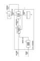
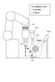
図1は、実施の形態1にかかるロボット制御装置1を適用して実現されるロボットシステム100の構成例を示す図である。
FIG. 1 is a diagram showing a configuration example of a
ロボットシステム100は、ロボット制御装置1と、ロボット2と、外界センサ3と、センサコントローラ4とを備える。なお、ロボットシステム100の構成は従来のロボットシステムと同様である。すなわち、ロボットシステム100は従来のロボットシステムのロボット制御装置を後述する本実施の形態にかかるロボット制御装置1に置き換えた構成である。 A
ロボット制御装置1は、ロボット2の本体と接続され、ロボット2に対する制御指令値を演算し、ロボット2内の図示を省略しているドライバユニットを介してモータに電流値を送って駆動している。ロボット2に対する制御指令値としては、位置指令値、速度指令値、加速度指令値とも称されるトルク指令値、などがある。ドライバユニットは、これらの制御指令値に基づいて、モータに出力すべきモータ電流値を演算する。図1に示す例ではロボット2に対する制御指令値を位置指令値1009としている。以下においても、制御指令値が一般的な産業用ロボットコントローラの制御指令値の一つである位置指令値である場合の例について説明する。 The
ここで、外界センサ3をロボット2の本体あるいは周辺環境に複数備えることで、ロボットシステムの周辺で生じる周辺環境の変化に応じてロボットを動作させることが可能となる。外界センサ3の例としては、ビジョンセンサ、モーショントラッカ、力覚センサ、触覚センサ、近接覚センサ、などが挙げられる。これらの外界センサ3を用いて作業対象物である認識対象を計測し、計測結果に基づいて演算された特徴量に基づいて指令値(本実施の形態では位置指令値)を生成あるいは修正して行う制御は、外界センサに基づく制御方式である。 Here, by providing a plurality of
以下、実施の形態1にかかるロボット制御装置1によるロボットの制御動作について、解決しようとする課題とともに詳しく説明する。 Hereinafter, the control operation of the robot by the
まず、課題について説明する。信号処理あるいは情報処理された認識結果に基づいてロボットを動作させるロボット制御にあっては、上述したように、複数のセンサを利用することがあるが、同一種類の複数センサを用いた制御系では「いずれかが1つは安定して動作する」ことが暗黙の前提となっており、不測の状態に対する制御系設計が従来の課題であった。また、異種の複数センサを利用する場合には、フィードバック制御を複数センサそれぞれに対して独立に設計することが主であり、作業状態に応じて複数センサを切り替えながらロボット制御を行う設計ができていなかった。 First, the problem will be explained. In robot control for operating a robot based on signal processing or information processing recognition results, a plurality of sensors may be used as described above. It is an implicit premise that "one of them operates stably", and control system design for unforeseen situations has been a conventional issue. In addition, when multiple sensors of different types are used, feedback control is mainly designed independently for each of the multiple sensors, and robot control can be designed by switching between multiple sensors according to the work state. I didn't.
たとえば、環境光の変化などの外乱によっては、センサによる計測結果を示すセンサ信号に著しい変化が生じ、その結果として、センサ信号の特徴量が正常に出力されなくなる場合がある。すなわち、異常な値を示すセンサ信号がセンサから出力される場合がある。正常に出力されない場合とは、たとえば、制御対象のロボットは緩やかに移動しているのにもかかわらずセンサ信号を信号処理して得られる特徴量が示す目標地点が突然大きく変化する場合、特徴量が出力されなくなる場合、誤って認識している複数の目標地点候補の中の幾つかの目標地点候補を、目標地点の出力するタイミングごとに違う目標地点を出力する場合、などがある。 For example, a disturbance such as a change in ambient light may cause a significant change in the sensor signal indicating the measurement result of the sensor, and as a result, the feature amount of the sensor signal may not be output normally. That is, the sensor may output a sensor signal indicating an abnormal value. When the output is not normal, for example, when the target point indicated by the feature value obtained by signal processing the sensor signal changes suddenly even though the robot to be controlled is moving slowly, the feature value is not output, or some target point candidates among a plurality of erroneously recognized target point candidates are output at different target point output timings.
この場合、複数のセンサ信号を特許文献1に記載のような方法で重み付け平均した結果をロボット制御で使用しても、必ずしも期待した動作が行われない場合がある。すなわち、センサ信号が示す計測結果あるいは計測結果の特徴量の確からしさを「信頼度」として定義する場合、信頼度が低下している場合には、次の2つの状態をとる。1つ目の状態は「複数センサで構成されているシステムの場合、適切なセンサ出力を選択すればロボットの動作が継続可能な場合」であり、2つ目の状態は「想定しているセンサ信号レベルあるいは特徴量抽出レベルを下回り、指令値が著しく変動することでロボットが暴走状態となり、継続して動作すると作業失敗を引き起こしてしまうリスクを伴う場合」である。これまでのロボット制御は、上記の2つの状態のいずれかとなった場合に自動的に制御出力を調整できる枠組みが無かった。 In this case, even if the results of weighted averaging of a plurality of sensor signals by the method described in
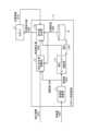
図2は、実施の形態1にかかるロボット制御装置1の構成例を示す図である。なお、図2では、ロボット制御装置1が制御するロボット2についても併せて記載している。 FIG. 2 is a diagram showing a configuration example of the
ロボット制御装置1は、信頼度演算部11、補正指令値演算部12、指令値生成部13および目標軌道保持部14を備える。 The
信頼度演算部11は、図1に示す外界センサ3が出力するセンサ信号をセンサコントローラ4が分析して得られる特徴量1005を入力とし、入力された特徴量1005の変化量に基づいて、センサ信号の信頼度Pcを計算する。なお、センサ信号は図1に示す信号1001に相当する。また、特徴量1005は図1に示すセンサコントローラ4の出力情報1002に含まれる。信頼度演算部11は、計算した信頼度Pcを信頼度1006として補正指令値演算部12に出力する。 The
補正指令値演算部12は、信頼度1006および上記特徴量1005を基にセンサコントローラ4で算出された補正情報1003を入力とし、入力された各情報に基づいて、ロボット2の軌道を補正するための軌道補正量を計算する。なお、補正情報1003は図1に示すセンサコントローラ4の出力情報1002に含まれる。補正指令値演算部12は、計算した軌道補正量1004を指令値生成部13に出力する。 Correction command value calculation unit 12 receives as
指令値生成部13は、軌道補正量1004、事前にプログラミングされた目標軌道を保持する目標軌道保持部14が出力する目標軌道1008、およびロボット2が出力するロボット2の位置情報1010を入力として、入力された各情報に基づいてロボット2に対する位置指令値を生成する。目標軌道1008は、プログラミングによって予め定められたロボット2の軌道を示す。軌道とは、3次元上のある時刻tのロボット位置指令値を一定の時間幅Δt刻みで表現したもののデータ群を表す。目標軌道の情報の一部がある時刻の位置指令値である。なお、位置情報1010は、ロボット2が有する内界センサによって生成される。指令値生成部13は、生成した位置指令値1009をロボット2に出力する。 The command
ここで、本実施の形態では、1つ以上の外界センサ3から出力される各センサ信号をセンサコントローラ4が信号処理して各センサ信号に対応する特徴量1005および補正情報1003を得る構成としているが、特徴量1005および補正情報1003を得るための信号処理をロボット制御装置1が行う構成としてもよい。この場合の構成については別の実施の形態として後述する。 Here, in this embodiment, each sensor signal output from one or more
以下、ロボット制御装置1の信頼度演算部11、補正指令値演算部12および指令値生成部13が行う処理について説明する。 Processing performed by the
図3は、実施の形態1にかかるロボット制御装置1の信頼度演算部11の動作の一例を示すフローチャートである。 FIG. 3 is a flow chart showing an example of the operation of the
信頼度演算部11は、図3に示すように、センサコントローラ4から出力される特徴量1005(以下、特徴量Vkと記載する場合がある)を取得し(ステップS11)、特徴量Vkに基づいて信頼度Pcを算出する(ステップS12)。そして、信頼度演算部11は、算出した信頼度Pcを補正指令値演算部12に出力する(ステップS13)。 As shown in FIG. 3, the
ここで、信頼度Pcは、0から1までの範囲の実数で定義される。特徴量Vkと信頼度Pcの詳細については後述するが、特徴量Vkは、ある外界センサSENk(k=1,2,…)が時刻tにおいて出力するセンサ信号Sk(t)を入力とし、センサ信号Sk(t)を定められた変換処理により数値化して表現されたスカラ量である特徴量Vk(t)、または、特徴量ベクトルVec_Vk(t)を用いて計算されるものである。時刻tに関する特徴量Vkの遷移である時系列情報としての特徴量Vk(t)、空間に基づく特徴量Vk(X)、あるいは、時間および空間に関して変化する特徴量Vk(t,X)があるときに、信頼度演算部11は、事前に予測されるモデルや仮定に基づいて、例えば期待される変化の上限Vthを用いて、上限Vthを超える特徴量Vkの変化の有無、特徴量Vkと上限Vthとの大小関係などに基づいて、期待されている上限Vthからの逸脱を指標化して信頼度Pcを算出する。特徴量Vkおよび信頼度Pcの詳細については後述する。 Here, the reliability Pc is defined as a real number ranging from 0 to 1. The feature quantity Vk and the reliability Pc will be described later in detail. It is calculated using the feature amount Vk(t), which is a scalar amount expressed by digitizing the signal Sk(t) by a predetermined conversion process, or the feature amount vector Vec_Vk(t). There is a feature Vk(t) as time-series information that is the transition of the feature Vk with respect to time t, a feature Vk(X) based on space, or a feature Vk(t,X) that changes with respect to time and space. At times, the
なお、以下の説明では、時刻を考慮することなく外界センサSENkが出力するセンサ信号を表現する場合はセンサ信号をSkと表現し、また、外界センサSENkが出力するセンサ信号(Sk)についての信頼度をPc(k)と表現する。 In the following explanation, when the sensor signal output by the external sensor SENk is expressed without considering the time, the sensor signal is expressed as Sk. We express the degree as Pc(k).
図4は、実施の形態1にかかるロボット制御装置1の補正指令値演算部12の動作の一例を示すフローチャートである。 FIG. 4 is a flow chart showing an example of the operation of the correction command value calculator 12 of the
補正指令値演算部12は、図4に示すように、センサコントローラ4から出力される補正情報1003および信頼度演算部11から出力される信頼度1006(Pc(k))を取得し(ステップS21)、補正情報1003および信頼度1006に基づいて軌道補正量1004を算出する(ステップS22)。そして、補正指令値演算部12は、算出した軌道補正量1004を指令値生成部13に出力する(ステップS23)。 As shown in FIG. 4, the correction command value calculation unit 12 acquires the
ステップS22において、補正指令値演算部12は、各外界センサ3が出力するセンサ信号Skに基づく補正情報1003(補正情報ΔXck)を信頼度Pc(k)によって重み付けして補正係数を求め、この補正係数を用いて軌道補正量1004を算出する。補正指令値演算部12は、例えば、補正係数Ck(k=1,2,…)として、下記の式(1)および式(2)に基づいて軌道補正量ΔXdを計算する。式(2)における「fnc」は信頼度Pc(k)から補正係数Ckを求める関数を示す。式(1)では補正係数Ckと補正情報ΔXckの積を各センサ毎の軌道補正量の要素として算出し、センサ全体として和を取って出力する。 In step S22, the correction command value calculation unit 12 obtains a correction coefficient by weighting the correction information 1003 (correction information ΔXck) based on the sensor signal Sk output from each
ΔXd = Σ(Ck・ΔXck) …(1)
Ck = fnc(Pc(k)) …(2)ΔXd = Σ(Ck ΔXck) …(1)
Ck = fnc(Pc(k)) (2)
なお、さらに目標軌道を補正指令値演算部12に入力する構成も可能である。この場合、軌道補正量ΔXdに対して上限値や補正方向を限定することが可能となる。例えば、基準になる位置指令値Xdを入力として、軌道補正量ΔXdの上限値ΔXdlimや補正対象とする方向を限定することができる。具体的には、目標軌道に鉛直な向きのみに補正をかける場合や、ロボットツール座標系に対してX,Y,ZあるいはXYZ軸回りの姿勢A,B,Cのうち1つ以上を選択してその方向のみに補正をかける場合がある。 It should be noted that a configuration in which the target trajectory is further input to the correction command value calculation unit 12 is also possible. In this case, it is possible to limit the upper limit value and correction direction for the trajectory correction amount ΔXd. For example, by inputting the reference position command value Xd, the upper limit value ΔXdlim of the trajectory correction amount ΔXd and the direction to be corrected can be limited. Specifically, when correcting only the vertical direction to the target trajectory, or selecting one or more of the postures A, B, and C around the X, Y, Z or XYZ axes for the robot tool coordinate system. may be corrected only in that direction.
図5は、実施の形態1にかかるロボット制御装置1の指令値生成部13の動作の一例を示すフローチャートである。 FIG. 5 is a flow chart showing an example of the operation of the
指令値生成部13は、図5に示すように、目標軌道保持部14から出力される目標軌道1008および補正指令値演算部12から出力される軌道補正量1004(ΔXd)を取得し(ステップS31)、目標軌道1008および軌道補正量1004に基づいて指令値を生成する(ステップS32)。指令値生成部13は、生成した指令値をロボット2に出力する(ステップS33)。ここでは、指令値生成部13は指令値として位置指令値1009を生成する。 As shown in FIG. 5, the command
ステップS32において、指令値生成部13は、例えば、時刻tにおける指令値Xout(t)、軌道補正量をΔXd(t)、目標軌道をXd(t)とすると、下記の式(3)に従って指令値を生成する。 In step S32, the command
Xout(t)=Xd(t)+ΔXd(t) …(3) Xout(t) = Xd(t) + ΔXd(t) (3)
指令値生成部13は、目標軌道Xd(t)の補正情報(ここでは軌道補正量ΔXd)が入力されなければ、元の目標軌道Xd(t)を指令値Xout(t)として出力してロボット2を動作させる。 The command
また、指令値生成部13は、別の形態として、これまでの補正量を積分した形式としてΣΔXd(t)を用いて、下記の式(4)に従って指令値を生成することも可能である。 Alternatively, the command
Xout(t)=Xd(t)+ΣΔXd(t) …(4) Xout(t) = Xd(t) + ΣΔXd(t) (4)
指令値Xoutの実現方法は、目標軌道Xd(t)および軌道補正量ΔXd(t)を用いている限り特に上記の式(3)または式(4)に示す内容に限定されるものではない。 A method of realizing the command value Xout is not particularly limited to the contents shown in the above formula (3) or (4) as long as the target trajectory Xd(t) and the trajectory correction amount ΔXd(t) are used.
なお、目標軌道1008はすべて事前に与えられている形で表現しているが、ロボット制御装置1の動作中にある起点Xsと終点Xeに対してオンラインで目標軌道を再計算する場合についても同様に適用できる。すなわち、目標軌道Xd(t)はロボット制御装置1の動作途中に更新することがある。また、ロボット制御装置1は、指令値生成部13に入力される目標軌道1008が指令値1回分(目標軌道を表す一連の位置指令値のうち、現在実行中の位置指令値Xd(t)の次の位置指令値Xd(t+1))などであっても同様に適用できる。 Note that the
以下、本実施の形態の構成を説明するために、特徴量Vkおよび信頼度Pcの定義について説明する。 Definitions of the feature amount Vk and the reliability Pc will be described below in order to describe the configuration of the present embodiment.
外界センサ3が出力するセンサ信号に基づく制御は、まず外界センサ3の計測結果(センサ信号)を用いて信号処理あるいは情報処理を実行して、特徴量を得る。特徴量は、外界センサ3の種類だけ多様な形態があるが、時刻tにおいて、ある外界センサSENk(k=1,2,…)のセンサ信号Sk(t)を変換処理し、特徴量として数値化して表現されたスカラ量Vk(t)あるいはベクトル量vec_Vk(t)を用いて計算される、という点は共通している。ベクトル量vec_Vk(t)は、1つの特徴量を取り扱う際に、さらに複数の独立した物理量に変換して表現できる場合に用いる。例えば、色味(RGB)と輝度(明暗)などを1つの画素に対して定義する場合、特徴量をベクトル量vec_Vk(t)として取り扱うものとする。 Control based on the sensor signal output by the
このとき、図6に示すように、時系列に特徴量Vkを評価する場合、t=taをデータ収集開始点として、Vk(t=ta+i)(i=1,2,3,…)としてデータを取得していく。また、空間として特徴量Vkを評価する場合、図7に示すように、Vk(t=ta,[x,y,za])という形式で表現する。変数としては、時間情報tと地点情報[x,y,z]が含まれている。この場合、地点情報z=zaは固定値である。また、x,yについては、センサ座標系上にセンサ要素が配列され、x方向とy方向にセンサが格子状に配置されている場合を表現している。特徴量Vkとしては、例えば480×640の画素数で表現されるビジョンセンサの各画素における色情報、輝度情報などを例示できる。同一時刻t=taにおいて空間として地点Xaにおける特徴量をVk(ta,Xa)とするときに地点Xaを複数点同時に評価する。さらに、地点Xaが空間的に広がっているものを時系列で捉えた場合がある。なお、地点情報にさらに空間における姿勢情報としてオイラー角やクオータニオンなどを追加した構成としてもよい。 At this time, as shown in FIG. 6, when evaluating the feature amount Vk in time series, Vk (t = ta + i) (i = 1, 2, 3, ...) with t = ta as the data collection start point We will acquire data as Also, when the feature amount Vk is evaluated as a space, it is expressed in the form of Vk (t=ta, [x, y, za]) as shown in FIG. Variables include time information t and point information [x, y, z]. In this case, point information z=za is a fixed value. Also, x and y represent the case where the sensor elements are arranged on the sensor coordinate system and the sensors are arranged in a grid pattern in the x and y directions. As the feature amount Vk, for example, color information, brightness information, etc., of each pixel of the vision sensor represented by the number of pixels of 480×640 can be exemplified. At the same time t=ta, a plurality of points Xa are evaluated simultaneously when the feature amount at the point Xa as a space is Vk(ta, Xa). Furthermore, there is a case where the spatial spread of the point Xa is captured in time series. It should be noted that a configuration in which Euler angles, quaternions, and the like are added as posture information in space to the point information may be used.
特徴量としては、他にも、外界センサSENkの電気信号を変換して物理量と等価な特徴量Vk(t)として表現できる。例えば、ひずみゲージに流れる電流変化を力の値と等価とする処理などがあげられる。物理量としては、距離、加速度、速度、回転速度、ひずみ量、軸力、モーメントなどがあげられる。これらの物理量は、取得した物理量を事前に設定した閾値と比較したり、取得した物理量と物理量の目標値との差分によりPID(Proportional Integral Differential)制御をかけたり、といった使い方ができる。ほかにも、これらの物理量を時刻t0からt1までの一定サンプル分(すなわちVk(t)、t0≦t≦t1)取り出し、機械学習等を用い、これを波形パターンあるいは波形特徴量として新しい特徴量として抽出しなおす方法もある。一定範囲の情報量を使った別の特徴量として、時刻t0にカメラ等で取得した一定範囲の画素Vk(t0,[jx,jy])の集合(すなわち、面として広がりをもつ画像情報Vk(t0,[jx,jy])、0≦jx≦480、0≦jy≦640)を入力として、画像処理して得られる認識対象の輪郭線、位置、あるいは事前に生成したリスト内の対象と認識対象との類似度、といったものがある。 As the feature amount, the electrical signal of the external sensor SENk can be converted to be expressed as a feature amount Vk(t) equivalent to the physical amount. For example, there is a process of equating a change in current flowing through a strain gauge with a force value. Physical quantities include distance, acceleration, speed, rotational speed, strain amount, axial force, moment, and the like. These physical quantities can be used by comparing the acquired physical quantity with a preset threshold value, or performing PID (Proportional Integral Differential) control based on the difference between the acquired physical quantity and the target value of the physical quantity. In addition, these physical quantities are taken out for a certain number of samples from time t0 to t1 (that is, Vk(t), t0 ≤ t ≤ t1), and using machine learning, etc., this is used as a waveform pattern or waveform feature quantity as a new feature quantity There is also a method of re-extracting as Another feature using a certain range of information is a set of pixels Vk(t0,[jx,jy]) in a certain range acquired by a camera or the like at time t0 (that is, image information Vk( t0,[jx,jy]), 0≤jx≤480, 0≤jy≤640) are input, and the contours and positions of recognition targets obtained by image processing, or recognition as targets in a list generated in advance There is a degree of similarity with the object.
特徴量Vkは、ロボット制御装置1において、「外界センサ3に映り込んだ対象物は、目的とする対象物か否か(識別)」、「外界センサ3の座標系に対して、対象物の存在する位置はどこか(認識、位置推定)」、「対象物の目標状態と現在状態との差異および差分の計算または抽出、差異または差分の計算または抽出(認識、差分抽出)」という目的のために用いられる。 The feature value Vk is determined by the
特徴量Vkは、目標とする特徴量Vdとの差異を認識し、ロボットのフィードバック制御を目的として使われることがある。特徴量Vkは、加速度センサまたは力覚センサのようにキャリブレーション処理を実施の後にはセンサ信号Sk(t)が物理量となる場合は、直接その物理量が所望の値になるようなフィードバック制御に用いられる。 The feature amount Vk is sometimes used for the purpose of feedback control of the robot by recognizing the difference from the target feature amount Vd. If the sensor signal Sk(t) becomes a physical quantity after performing calibration processing, such as an acceleration sensor or a force sensor, the feature quantity Vk is directly used for feedback control so that the physical quantity becomes a desired value. be done.
一方で、センサ信号から抽出した特徴量である第1の特徴量から第2の特徴量をさらに抽出し、第2の特徴量を使用して処理を行う場合がある。例えば、センサ信号から抽出した画像情報のように、第1の特徴量(画像情報)そのもののデータではなく、第1の特徴量を入力としてさらに画像情報中の輪郭を抽出するエッジ抽出処理、対象物体の方向を抽出し画像情報の主成分分析処理など、データ処理を通じて得られる位置、方向などの情報を使う場合がある。これは、第1の特徴量から第2の特徴量を抽出することに相当する。第2の特徴量を用いて判定処理、フィードバック制御などを行うこともある。 On the other hand, there is a case where a second feature amount is further extracted from the first feature amount, which is the feature amount extracted from the sensor signal, and processing is performed using the second feature amount. For example, as in image information extracted from a sensor signal, edge extraction processing in which the first feature amount (image information) is not the data itself, but the first feature amount is used as input to further extract the contour in the image information. Information such as position and direction obtained through data processing such as principal component analysis processing of image information by extracting the direction of an object may be used. This corresponds to extracting the second feature amount from the first feature amount. Judgment processing, feedback control, etc. may be performed using the second feature amount.
また、第2の特徴量の抽出においては、時系列データの一部を切り出して波形のパターンとして学習したり、膨大な事前データから教師あり機械学習を利用して目標状態を獲得したりするなど、様々な手法を適用してよい。 In addition, in the extraction of the second feature quantity, a part of the time-series data is cut out and learned as a waveform pattern, or a target state is acquired using supervised machine learning from a huge amount of prior data. , various techniques may be applied.
ここで、作業対象物を目的位置に遷移させるために用いる特徴量から生成される補正情報について説明する。本実施の形態においては、ロボット2と作業対象物の作用力に基づくロボット手先の位置の補正量を、補正情報1003として例示できる。具体的には、6自由度の力センサから出力される計測量S1(sk,k=1)を力またはトルクの単位[NまたはNm]にキャリブレーションした後の出力である力センサ出力の時刻Tの値を特徴量V1(T)とする。このとき、ロボットエンドエフェクタに力が過剰にかからない制御を行うために、力の目標値を特徴量の目標値Vdとして、特徴量V1(T)に基づいてロボット手先の位置の補正量ΔXckを定義することができる。以上の定義に基づいて、適当な係数K1と置くと、下記の式(5)に従って特徴量V1(T)から補正量ΔXck(T)を求めることができる。 Here, the correction information generated from the feature amount used for transitioning the work object to the target position will be described. In this embodiment, the
ΔXck(T)=K1・(Vd-V1(T)) …(5) ΔXck(T)=K1・(Vd-V1(T)) …(5)
ここでは、この補正量ΔXck(T)は位置補正量(補正情報1003の一形態)となっている。ほかにも、補正量ΔXck(T)として、速度補正量、加速度補正量、加加速度補正量といった補正量が特徴量Vkに基づいて計算される。 Here, this correction amount ΔXck(T) is a position correction amount (one form of the correction information 1003). In addition, as the correction amount ΔXck(T), a correction amount such as a velocity correction amount, an acceleration correction amount, and a jerk correction amount is calculated based on the feature amount Vk.
なお、本明細書において目的位置などの「位置」という表現が意味しているのは、位置が3自由度および姿勢が3自由度の合計6自由度の3次元空間自由度のことであり、ロボット座標系Σrobに対するX,Y,Zの並進方向の位置とX,Y,Zの軸回りの回転によって一意に定まるロボット先端部の位置情報および姿勢情報と等価である。他にも外界センサ3に基づいて、認識対象の移動速度、認識対象の移動加速度、ロボット2と外部との接触状態に応じて発生する力(作用力)、ロボット手先位置と認識対象の相対距離、相対位置、相対速度、相対加速度、といったものが挙げられる。その場合も、速度情報や加速度情報も同様に、回転速度や回転加速度は省略した表現となり、実際には、並進方向3自由度と回転方向3自由度の合計6自由度を取り扱う。 In this specification, the expression "position" such as target position means a three-dimensional spatial degree of freedom with a total of six degrees of freedom, including three degrees of freedom for position and three degrees of freedom for orientation. It is equivalent to the position information and orientation information of the robot tip that are uniquely determined by the positions in the translation directions of X, Y, and Z with respect to the robot coordinate system Σrob and the rotations around the axes of X, Y, and Z. In addition, based on the
次に、特徴量に基づいて信頼度を計算する方法について説明する。 Next, a method for calculating reliability based on feature amounts will be described.
外界センサSENk(k=1,2,…)の出力であるセンサ信号Skで得られる特徴量Vk(k=1,2,…)について、その特徴量Vkの時間t(t=1,2,…)的、あるいは、空間X(X=[x,y,z])的に違う特徴量Vk(t,X=[x,y,z])に対して、その2つ以上の特徴量の相関情報に基づいて、各センサ信号Sk(k=1,2,…)に基づく特徴量Vk(k=1,2,3,…)に対する信頼度Pcを定義する。 For the feature quantity Vk (k = 1, 2, …) obtained from the sensor signal Sk, which is the output of the external sensor SENk (k = 1, 2, …), the time t (t = 1, 2, …) of the feature quantity Vk …) or spatially X (X=[x,y,z]) different feature values Vk (t,X=[x,y,z]), the two or more feature values Based on the correlation information, a reliability Pc is defined for the feature amount Vk (k=1, 2, 3, . . . ) based on each sensor signal Sk (k=1, 2, . . . ).
信頼度Pcは、時間tおよび空間Xに関連付けて定義された特徴量Vkがあるときに、事前に予測されるモデルおよび仮定に基づいて期待される変化の上限を超えるVkの変化の有無に基づいて定義される。信頼度Pcは、特徴量Vkのタイプごとに計算方法が異なるため、タイプごと分けて説明する。 Confidence Pc is based on whether, given a feature Vk defined in relation to time t and space X, the change in Vk exceeds the upper limit of expected change based on a priori predicted models and assumptions. defined as Since the calculation method of the reliability Pc differs for each type of the feature amount Vk, it will be described separately for each type.
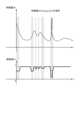
まず、特徴量Vkが時系列で取り扱われる「Vk(t)」の場合の信頼度Pcの計算方法について説明する。図8は、実施の形態1にかかる信頼度演算部11が信頼度Pcを計算する方法の第1の例を説明するための図である。 First, a method of calculating the reliability Pc when the feature amount Vk is "Vk(t)" handled in time series will be described. FIG. 8 is a diagram for explaining a first example of a method for calculating the reliability Pc by the
図8に示すように、特徴量Vkが時系列の情報Vk(t,[xa,ya,za])である場合、信頼度Pcは、ある時刻taの特徴量Vk(ta)に対する過去履歴であるVk(ta-i)(i=1,2,3,…)に基づいて求められる。具体的には、信頼度Pcは、今回の特徴量Vk(ta)の時間あたりの変化量が変化量の上限値ΔVthを超えるか否かに基づいて求められる。別の方法として、信頼度Pcは、上限値ΔVthと、特徴量Vkの一定時間幅Tの履歴の平均値(すなわち移動平均)とを用いて、特徴量Vkの移動平均が上限値ΔVthを超えるか否かに基づいて求めることもできる。また、上限値ΔVthは、直前の値との直接比較、すなわち、時間的に隣り合った2つの特徴量Vkの差に対する上限としても定義できる。ここで、図8に表す例では、信頼度Pcを下記の式(6)および式(7)で表現することができる。 As shown in FIG. 8, when the feature amount Vk is time-series information Vk(t,[xa,ya,za]), the reliability Pc is the past history for the feature amount Vk(ta) at a certain time ta. It is obtained based on a certain Vk(ta-i) (i=1,2,3,...). Specifically, the reliability Pc is obtained based on whether or not the amount of change per hour of the current feature amount Vk(ta) exceeds the upper limit value ΔVth of the amount of change. As another method, the reliability Pc is calculated by using the upper limit value ΔVth and the average value (that is, moving average) of the history of the feature value Vk for a certain time width T, and the moving average of the feature value Vk exceeds the upper limit value ΔVth. It can also be determined based on whether The upper limit value ΔVth can also be defined as an upper limit for direct comparison with the immediately preceding value, that is, for the difference between two temporally adjacent feature quantities Vk. Here, in the example shown in FIG. 8, the reliability Pc can be expressed by the following equations (6) and (7).
Pc=[{Vk(t)-Vk(t-1)}/Δt-ΔVth] if{Vk(t)-Vk(t-1)}/Δt>ΔVth …(6)
Pc=1 if{Vk(t)-Vk(t-1)}/Δt≦ΔVth …(7)Pc=[{Vk(t)-Vk(t-1)}/Δt-ΔVth] if {Vk(t)-Vk(t-1)}/Δt>ΔVth (6)
Pc=1 if {Vk(t)-Vk(t-1)}/Δt≦ΔVth (7)
次に、特徴量Vkが空間的に取り扱われる「Vk(ta,[x,y,za])」である場合の信頼度Pcの計算方法について説明する。 Next, a method of calculating the reliability Pc when the feature amount Vk is "Vk (ta, [x, y, za])" handled spatially will be described.
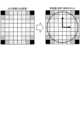
特徴量Vkが空間的情報Vk(ta,[x,y,za])である場合、信頼度Pcは、ある時刻taのX,Y方向に面上に広がりを持つ空間のある地点[x,y,za](ex. x=1,2,3,…、y=1,2,3,…、z=za(固定))の空間的情報Vk(ta,[x,y,za])に基づいて、空間上のVk(t,[x,y,z])の分布がどうであるかを評価するものである。時系列の特徴量Vkのみに注目しているときに比べると、空間的にとらえている場合の方が情報量が多く、特徴量Vk(ta,[x,y,za])の一定量の計算範囲を探索すると「空間中の対象が移動している」あるいは「突然何かが作業対象物の前に現れている」ということが判別可能となる。一例として、RGBカメラを用いて得られる画像が空間的に取り扱われる特徴量Vkに相当する。この他にも、格子状にセンサを配置したセンサアレイから得られるセンサ信号も同様のことがいえる。 When the feature value Vk is spatial information Vk (ta, [x, y, za]), the reliability Pc is a point [x, y,za] (ex. x=1,2,3,..., y=1,2,3,..., z=za (fixed)) spatial information Vk (ta,[x,y,za]) is used to evaluate the distribution of Vk(t,[x,y,z]) in space. Compared to when focusing only on the time-series feature Vk, the amount of information is larger when the spatial view is taken, and a certain amount of the feature Vk(ta,[x,y,za]) By searching the calculation range, it becomes possible to determine that "the object in space is moving" or "something suddenly appears in front of the work object". As an example, an image obtained using an RGB camera corresponds to the feature amount Vk that is spatially handled. The same applies to sensor signals obtained from a sensor array in which sensors are arranged in a grid pattern.
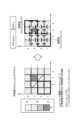
このような特徴量Vk(t,[x,y,z])は情報量が多いので、より低次元で制御しやすい第2の特徴量Vk2に変換してから信頼度Pcを計算することがある。この場合の信頼度演算部11の動作について図9を用いて説明する。図9は、実施の形態1にかかる信頼度演算部11が信頼度Pcを計算する方法の第2の例を説明するための図である。図9に示す例では、信頼度演算部11は、ある地点X1とこれに隣り合った地点X2に関する情報から、第2の特徴量Vk2(t,[X1,X2])を生成する。図9の例では、第2の特徴量Vk2として勾配情報「grad x」および「grad y」が得られるとする。「grad x」は、x軸方向での特徴量Vkの勾配を示し、「grad y」は、y軸方向での第1の特徴量Vkの勾配を示す。勾配情報は、空間的に隣り合った上記の特徴量Vkの差に基づいて計算される。図9の例の場合は、(x,y)=(3,3)において特徴量Vkが非常に小さい値となっている。このとき、例えば、「近傍空間においてVkについては急峻な変化は無い」という前提がある場合には、以下に示す方法で信頼度を求めることができる。 Since such a feature quantity Vk(t,[x,y,z]) has a large amount of information, it is possible to convert it to a second feature quantity Vk2 that is lower in dimension and easier to control before calculating the reliability Pc. be. The operation of the
ここでは、一定の計算範囲を定義して信頼度を計算する場合の例を説明する。以下では、図9に示すx1からx2およびy1からy2の範囲を[(x1,x2),(y1,y2)]と表現する。この場合、この範囲の信頼度は下記の式(8)で表現される。 Here, an example in which a certain calculation range is defined and the reliability is calculated will be described. Below, the ranges from x1 to x2 and from y1 to y2 shown in FIG. 9 are expressed as [(x1, x2), (y1, y2)]. In this case, the reliability in this range is expressed by the following equation (8).
Pc[(x1,x2),(y1,y2)]=1-max(grad x,grad y,[(x1,x2),(y1,y2)]) …(8) Pc[(x1,x2),(y1,y2)]=1-max(grad x,grad y,[(x1,x2),(y1,y2)]) …(8)
式(8)で表現される信頼度の計算では、図9に示す太い線で囲んだ枠内の[grad x],[grad y]を入力として、入力された合計4つの勾配の中から値が最大の勾配を探し、勾配の最大値に基づいて、勾配が大きいほど信頼度が低くなるようにしている。ここでの勾配とは、空間的に隣り合った2つの特徴量の間の変化量を意味する。図9に示す例では、(x,y)=(3,3)における特徴量Vkが周辺よりも小さく、また、(x,y)=(3,3)以外の地点における特徴量Vkは同じである。また、(x,y)=(3,3)における特徴量Vkとこれに隣り合った各地点における特徴量Vkとの勾配は、すべて0.7である。そのため、(x,y)=(3,3)が含まれない範囲ではPc[(x1,x2),(y1,y2)]=1.0となり、(x,y)=(3,3)が含まれる範囲ではPc[(x1,x2),(y1,y2)]=0.3となる。例えば、図9に示すように、範囲[(1,2),(1,2)]の信頼度はPc[(1,2),(1,2)]=1.0であり、範囲[(3,4),(3,4)]の信頼度はPc[(3,4),(3,4)]=0.3である。 In the calculation of the reliability expressed by Equation (8), the [grad x] and [grad y] in the frame surrounded by the thick line shown in Fig. 9 are input, and the value is selected from the total of four input gradients. , and based on the maximum value of the gradient, the higher the gradient, the lower the confidence. The gradient here means the amount of change between two spatially adjacent feature quantities. In the example shown in FIG. 9, the feature value Vk at (x,y)=(3,3) is smaller than the surrounding area, and the feature value Vk at points other than (x,y)=(3,3) is the same. is. Also, the gradients of the feature value Vk at (x,y)=(3,3) and the feature value Vk at each point adjacent thereto are all 0.7. Therefore, in the range not including (x,y)=(3,3), Pc[(x1,x2),(y1,y2)]=1.0 and (x,y)=(3,3) is included, Pc[(x1,x2),(y1,y2)]=0.3. For example, as shown in FIG. 9, the reliability of the range [(1,2),(1,2)] is Pc[(1,2),(1,2)]=1.0, and the range [ The reliability of (3,4),(3,4)] is Pc[(3,4),(3,4)]=0.3.
以上のように、特徴量Vkは外界センサ3が出力するセンサ信号Skを物理量などの数値演算可能な情報に変換したものを総称したもので定義している。また、時系列または空間に基づく特徴量Vkがある場合、事前に予測されるモデルまたは仮定に基づいて、例えば期待される変化の上限Vthに基づき、それを超えるVkの変化の有無、VthとVkの大小関係などから信頼度Pcが計算される。 As described above, the feature amount Vk is defined as a generic term for information obtained by converting the sensor signal Sk output from the
このように定義される信頼度Pcは、次の点で上記の特許文献1に記載の技術で使用されている従来の信頼度と比較して優れている。従来の信頼度は、センサからの出力データあるいは距離情報としての特徴量に関して、その出力の確からしさを「出力の絶対量」を利用して、それを直接信頼度として定義している。一方、本実施の形態にかかるロボットシステム100で使用する信頼度Pcは、センサ出力であるセンサ信号Skを特徴量Vkに変換した上で、前後の時系列や空間的な変化に基づいて定義している。この違いがあるため、本実施の形態にかかるロボット制御装置1は、時間的に過去の履歴である特徴量Vk(t)および近傍空間の特徴量Vk(X)の一方または双方を考慮してロボット2の制御を高精度に行うことが可能となる。 The reliability Pc defined in this way is superior to the conventional reliability used in the technique described in
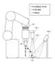
一例として、図10に示す構成のロボットの制御について説明する。図10は、実施の形態1にかかるロボット制御装置1が適用されるロボットシステムの具体例を示す図である。図10に示すロボットシステムは、組み立て操作を行うロボットを含み、外界センサとして、力覚センサ201と、ビジョンセンサ202-1および202-2とが設置されている。このようなロボットシステムにおいて、ロボット制御装置1がロボットを制御して、エンドエフェクタが把持した作業対象物である物体300を位置301まで移動させるものとする。このとき、ロボットの本体に設置されたビジョンセンサ202-1は、視野203-1の範囲を撮影し、撮影結果をセンサ信号として出力している。このロボットシステムにおいて、ロボット制御装置1は、ビジョンセンサ202-1が出力するセンサ信号から算出される補正情報Aと目標軌道に基づいて、図11に示すようにエンドエフェクタを移動させる。図11は、図10に示すロボットシステムにおけるロボットの目標軌道と実軌道と補正情報との関係の一例を示す図である。 As an example, the control of the robot configured as shown in FIG. 10 will be described. FIG. 10 is a diagram showing a specific example of a robot system to which the
このとき、図12に示すような環境中へ異物または人などが障害物として侵入した場合、ロボット制御装置1は、特徴量Vkの信頼度Pcに基づいて障害物を検出し、状況に応じた行動をとる。例えば、ロボット制御装置1は、図9を用いて説明したような信頼度を算出する場合、ある地点の信頼度が周辺の信頼度よりも低い場合、信頼度が低い地点を避けるようにロボットを制御する。例えば、ロボット制御装置1は、エンドエフェクタの軌道を修正する、移動速度を変更する、移動を一時的に停止させる、などの制御をロボット2に対して実施する。このときのエンドエフェクタの目標軌道と実際の軌道(実軌道)の関係は図13に示すものとなる。これにより、ロボット2および物体300と障害物との衝突が発生するなどしてロボットシステム100が破損してしまうのを防止できる。また、ロボットシステム100の破損を防止できることにより、長時間にわたってラインが停止する事態となるのを回避でき、ラインの停止時間の低減を実現することができる。 At this time, if a foreign object or a person enters the environment as an obstacle as shown in FIG. take action. For example, when calculating the reliability as described with reference to FIG. 9, if the reliability of a certain point is lower than the reliability of the surroundings, the
ここで、実施の形態1にかかるロボット制御装置1のハードウェア構成について説明する。図14は、ロボット制御装置1を実現するハードウェアの一例を示す図である。 Here, the hardware configuration of the
ロボット制御装置1は、例えば、図14に示す演算装置101、記憶装置102およびインタフェース回路103により実現することができる。演算装置101の例は、CPU(Central Processing Unit、中央処理装置、処理装置、演算装置、マイクロプロセッサ、マイクロコンピュータ、DSP(Digital Signal Processor)ともいう)、システムLSI(Large Scale Integration)などである。記憶装置102の例は、RAM(Random Access Memory)、ROM(Read Only Memory)、ハードディスクドライブ、SSD(Solid State Drive)、着脱可能なメモリデバイス、またはこれらを組み合わせたものである。 The
ロボット制御装置1の信頼度演算部11、補正指令値演算部12および指令値生成部13は、これらの各部として動作するためのプログラムを演算装置101が実行することにより実現される。信頼度演算部11、補正指令値演算部12および指令値生成部13として動作するためのプログラムは記憶装置102に予め格納されている。演算装置101は、上記のプログラムを記憶装置102から読み出して実行することにより、信頼度演算部11、補正指令値演算部12および指令値生成部13として動作する。また、目標軌道保持部14は記憶装置102により実現される。 The
記憶装置102は、上記のプログラムを保持するとともに、演算装置101が各種処理を実行する際の一時メモリとしても使用される。インタフェース回路103は、ロボット制御装置1がロボット2およびセンサコントローラ4との間でデータを送受信する際に使用される。 The storage device 102 holds the above programs and is also used as a temporary memory when the arithmetic device 101 executes various processes. The
なお、ロボット制御装置1の各部として動作するための上記のプログラムは記憶装置102に予め格納されているものとしたがこれに限定されない。上記のプログラムは、CD(Compact Disc)-ROM、DVD(Digital Versatile Disc)-ROMなどの記録媒体に書き込まれた状態でユーザに供給され、ユーザが記憶装置102にインストールする形態であってもよい。また、上記のプログラムは、インターネットなどのネットワークを介してユーザに提供される形態であってもよい。ロボット制御装置1を実現するハードウェアの例について説明したが、後述する実施の形態2以降で説明する各ロボット制御装置も同様のハードウェアで実現することができる。 It is assumed that the above programs for operating each part of the
実施の形態2.
つづいて、実施の形態2にかかるロボット制御装置について説明する。実施の形態2にかかるロボット制御装置の構成は実施の形態1と同様である(図2参照)。本実施の形態では実施の形態1と異なる部分について説明する。
Next, a robot control device according to a second embodiment will be described. The configuration of the robot control device according to the second embodiment is the same as that of the first embodiment (see FIG. 2). In this embodiment mode, portions different from those in
実施の形態2にかかるロボット制御装置1においては、実施の形態1で説明した信頼度演算部11が、2つ以上の外界センサ3のセンサ信号から得られる2つ以上の特徴量1005(Vk,Vk+1,…)を用いて信頼度を計算する点が実施の形態1と異なる。 In the
実施の形態2にかかる信頼度演算部11は、ある外界センサSENkが出力するセンサ信号Skの特徴量Vkに対して算出した信頼度Pc(k)が、特徴量Vkが急激に変化したことにより1より小さい値となった場合、他の外界センサSENk+1に関する特徴量Vk+1を確認し、特徴量Vk+1も同時に低下傾向がみられる場合には、実際に変化が起きているものとして取り扱う。すなわち、信頼度演算部11は、特徴量Vkそのものの信頼度Pc(k)は低くないとし、信頼度Pc(k)を、特徴量Vk+1または信頼度Pc(k+1)に基づいて、大きな値に補正する。この処理は、下記の式(9)および(10)で表わされる。式(9)において、Kwは重み係数であり、Kwが小さいほど、他の外界センサSENk+1からのセンサ信号の特徴量の値が近いときに信頼度Pcを1に近づける設定となる。 The
Pc(k)=Pc(k)+(1-Pc(k))/{1+Kw・ABS(Pc(k)-Pc(k+1))}
When {Pc(k)-Pc(k+1)}≦ΔPc_th …(9)
Pc(k)=Pc(k) When {Pc(k)-Pc(k+1)}>ΔPc_th …(10)Pc(k)=Pc(k)+(1-Pc(k))/{1+Kw・ABS(Pc(k)-Pc(k+1))}
When {Pc(k)-Pc(k+1)}≤ΔPc_th (9)
Pc(k)=Pc(k) When {Pc(k)-Pc(k+1)}>ΔPc_th (10)
他にも、2つ以上の種類の異なる外界センサ3を用いた場合、補正指令値演算部12によるセンサ信号Skに対応する軌道補正量の演算に関して、補正指令値演算部12は、別種類の外界センサSENkが出力するセンサ信号Sk+1に対応する信頼度Pc(k+1)が高く、有意な補正量ΔXck+1を出力している場合、センサ信号Skに関する補正量ΔXckの重み係数wkを小さくする構成とすることが考えられる。ただし、wkは|wk|<1で定義されるものとし、下記の式(11)~(13)のように軌道補正量ΔXdが定義できる。 In addition, when two or more different types of
ΔXd = Σ(Ck・wk・ΔXck) …(11)
Ck = fnc(Pc(k)) …(12)
wk = fnc(Pc(k+1),Xck+1) …(13)ΔXd = Σ(Ck・wk・ΔXck) (11)
Ck = fnc(Pc(k)) (12)
wk = fnc(Pc(k+1),Xck+1) (13)
この時の補正指令値演算部12の処理は、具体的には次のような事例が考えられる。たとえば、図12に示すようなロボットシステムにおいて、ビジョンセンサSENk(ビジョンセンサ202-1)と、ロボットのエンドエフェクタやワーク等の物体300と周辺環境との接触に関する力情報を取得する力覚センサSENk+1(力覚センサ201)とが装着され、ロボット2は組み立て作業を実施するタスクを行う。この条件で、補正指令値演算部12がビジョンセンサSENkに関する軌道補正量の計算を行う場合を考える。補正指令値演算部12は、ビジョンセンサSENkが出力するセンサ信号Skの信頼度に基づく補正係数Ckとは独立した指標として、重み係数wkを、力覚センサSENk+1が出力するセンサ信号Sk+1に基づいて自動調整することが可能である。例えば、力覚センサSENk+1が出力するセンサ信号Sk+1の値が定められた閾値よりも大きい場合は接触状態であるとし、重み係数wkを1よりかなり小さい値とする。一方、力覚センサSENk+1が出力するセンサ信号Sk+1の値が定められた閾値以下で接触状態ではない場合(すなわちXck+1がほぼ0の場合)は重み係数wkをほぼ1とする。この調整は、エンドエフェクタと障害物などが接触状態にあり、ビジョンセンサが出力するセンサ信号に基づいて演算される補正量(位置補正量)に従って軌道補正を行うと接触状態が悪化する場合に有効である。 Specifically, the following cases can be considered for the processing of the correction command value calculation unit 12 at this time. For example, in a robot system as shown in FIG. 12, a vision sensor SENk (vision sensor 202-1) and a force sensor SENk for acquiring force information regarding contact between an end effector of the robot, an
以上のような構成により、2つ以上の複数の外界センサ3を備えるよりロボットシステム100で補正指令値生成を行うロボット制御装置1においては、特に、ある外界センサ3の他の外界センサ3に対応する信頼度1006(信頼度Pc(k+1))あるいは補正情報1003を使って信頼度Pc(k)の補正が可能となる。これによって、異物混入や人侵入といったイレギュラー状態をセンサの故障と切り離した形で検出し、動作継続および早期の異常状態検出といったことが可能となる。この結果、生産システムの停止時間の短縮、生産効率の向上といった格別の効果を得ることができる。 With the configuration as described above, in the
実施の形態3.
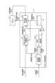
図15は、実施の形態3にかかるロボット制御装置1aの構成例を示す図である。ロボット制御装置1aは、実施の形態1にかかるロボット制御装置1に、さらに補正オーバーライド演算部15を追加し、指令値生成部13を指令値生成部13aに置き換えた構成である。図15においては、実施の形態1にかかるロボット制御装置1と同じ構成要素に同一の符号を付している。本実施の形態では実施の形態1と異なる部分について説明する。
FIG. 15 is a diagram showing a configuration example of a
補正オーバーライド演算部15では、信頼度演算部11が算出する信頼度1006に基づいて、目標軌道を進む速度指標であるオーバーライド値の補正を行い補正オーバーライドを生成する。補正オーバーライド演算部15は、信頼度1006が低いほど補正オーバーライドが低くなるように補正オーバーライド1007を演算し、指令値生成部13aに出力する。指令値生成部13aは、軌道補正量1004と、目標軌道1008と、ロボット2の内界センサによる計測結果に基づく位置情報1010と、補正オーバーライド1007とに基づいて位置指令値1009を生成する。 Based on the
図16は、実施の形態3にかかるロボット制御装置1aの補正オーバーライド演算部15の動作の一例を示すフローチャートである。 FIG. 16 is a flow chart showing an example of the operation of the correction override calculation section 15 of the
補正オーバーライド演算部15は、図16に示すように、信頼度演算部11から出力される信頼度1006を取得し(ステップS41)、信頼度1006に基づいて、指令値の補正に用いる補正係数として補正オーバーライドを算出する(ステップS42)。そして、補正オーバーライド演算部15は、算出した補正オーバーライド1007を指令値生成部13aに出力する(ステップS43)。 As shown in FIG. 16, the correction override calculation unit 15 acquires the
ここで、補正オーバーライドは例えば0~100%で定義することができる。この場合、補正オーバーライドが0%であればロボット2が進むことを止め、補正オーバーライドが100%であればロボット2は目標軌道で設計されていた速度で動作を行う。なお、これ以降の説明では、補正オーバーライドをOvrdCと記載する場合がある。また、これ以降の説明では、補正オーバーライドOvrdCは基本的には1.0を初期値として、0~1の範囲の実数を取るものとする。補正オーバーライド演算部15では、センサ毎の複数の補正オーバーライドOvrdC(k)を演算する。 Here, the correction override can be defined, for example, from 0 to 100%. In this case, if the correction override is 0%, the
図17は、実施の形態3にかかるロボット制御装置1aの指令値生成部13aの動作の一例を示すフローチャートである。 FIG. 17 is a flow chart showing an example of the operation of the command value generator 13a of the
指令値生成部13aは、図17に示すように、目標軌道保持部14から出力される目標軌道1008(Xd)、補正指令値演算部12から出力される軌道補正量1004(ΔXd)および補正オーバーライド演算部15から出力される補正オーバーライド1007(OvrdC)を取得し(ステップS51)、目標軌道1008、軌道補正量1004および補正オーバーライド1007に基づいて指令値を生成する(ステップS52)。指令値生成部13aは、生成した指令値をロボット2に出力する(ステップS53)。 As shown in FIG. 17, the command value generation unit 13a generates a target trajectory 1008 (Xd) output from the target
ステップS52において、指令値生成部13aは、入力された目標軌道Xdあるいは軌道補正量ΔXdの実行量を補正オーバーライドOvrdC(0~1)に基づいて補正することで、速度変化と等価の処理を行い、指令値を生成する。たとえば、信頼度Pcの低下に伴い補正オーバーライドOvrdCが低下すると、ロボット手先の移動速度を低減させる方向に作用する。 In step S52, the command value generator 13a corrects the input target trajectory Xd or the execution amount of the trajectory correction amount ΔXd based on the correction override OvrdC (0 to 1), thereby performing processing equivalent to speed change. , to generate the command value. For example, when the correction override OvrdC decreases as the reliability Pc decreases, it acts to reduce the movement speed of the robot hand.
例えば、図18に示したような事例、すなわち、ロボット2に取り付けられたビジョンセンサ202-2の視野203-1に障害物がある場合を考える。図18に示すケースでは、指令値生成部13aが補正情報ΔXdとともに取得した信頼度Pcが低い値となり、これに伴い補正オーバーライドOvrdCが低下する。結果として、ロボット2は、図19に示すように、障害物が無い場合の軌道である、一点鎖線の下向き矢印211で示す目標軌道通りに進むのではなく、太い実線の下向き矢印212に従って、減速した形で動作を継続する。 For example, consider the case shown in FIG. 18, that is, the case where there is an obstacle in the field of view 203-1 of the vision sensor 202-2 attached to the
事前に与えられている目標軌道Xdが位置の点列で与えられている場合、指令値生成部13aは、目標軌道Xdを、各地点における制御周期毎の次目標位置への移動速度vdに換算し、移動速度vdが低減した場合の1制御周期分の移動量から、補正オーバーライドOvrdC適用後の目標位置Xdcを演算する。 When the target trajectory Xd given in advance is given as a point sequence of positions, the command value generation unit 13a converts the target trajectory Xd into a moving speed vd to the next target position for each control cycle at each point. Then, the target position Xdc after application of the correction override OvrdC is calculated from the amount of movement for one control cycle when the movement speed vd is reduced.
補正オーバーライド演算部15が信頼度1006に基づいて算出する補正オーバーライドOvrdCは、例えば下記の式(14)に示すように、複数のセンサ信号Skに関する信頼度Pc(k)の中の最小値と定義することができる。 The correction override OvrdC calculated by the correction override calculation unit 15 based on the
OvrdC = min(Pc(k)) …(14) OvrdC = min(Pc(k)) (14)
他にも、補正オーバーライド演算部15が、複数のセンサ信号Skそれぞれに対応する複数の補正オーバーライドOvrdC(k)を出力し、指令値生成部13aは、複数のセンサ信号Skそれぞれに対応する複数の補正情報ΔXckのうち、もっとも軌道補正量ΔXdへの割合が大きいものに対応する補正オーバーライドOvrdC(k)を選択して指令値の生成を行うような方法がある。 In addition, the correction override calculation unit 15 outputs a plurality of correction overrides OvrdC(k) corresponding to each of the plurality of sensor signals Sk, and the command value generation unit 13a outputs a plurality of correction overrides OvrdC(k) corresponding to each of the plurality of sensor signals Sk. There is a method of selecting the correction override OvrdC(k) corresponding to the correction information ΔXck that has the largest ratio to the trajectory correction amount ΔXd to generate the command value.
以上のような構成を有する補正オーバーライド演算部15を実施の形態1にかかるロボット制御装置1に追加してロボット制御装置1aとすることで、ロボットシステム100の動作中に、異物の混入、人の侵入といったイレギュラー状態を、外界センサ3の故障と切り離した形で検出し、低速による動作継続あるいは衝突することなく異常状態検出が可能となる。この結果、生産システムの停止時間の短縮、生産効率の向上といった格別の効果を得ることができる。 By adding the correction override calculation unit 15 having the configuration as described above to the
実施の形態4.
図20は、実施の形態4にかかるロボット制御装置1bの構成例を示す図である。ロボット制御装置1bは、実施の形態3にかかるロボット制御装置1aの補正オーバーライド演算部15を補正オーバーライド演算部15bに置き換えた構成である。図20においては、実施の形態3にかかるロボット制御装置1aと同じ構成要素に同一の符号を付している。本実施の形態では実施の形態3と異なる部分について説明する。
FIG. 20 is a diagram showing a configuration example of a robot control device 1b according to the fourth embodiment. The robot control device 1b has a configuration in which the correction override calculation unit 15 of the
実施の形態3の補正オーバーライド演算部15の処理と実施の形態4の補正オーバーライド演算部15bの処理の違いは、補正オーバーライドOvrdC(k)を演算する際に、対象とする外界センサ3である第1の外界センサのセンサ信号Skの信頼度1006(Pc(k))に加えて、他の外界センサ3である第2の外界センサのセンサ信号Sk+1の特徴量1005(Vk+1)を補正オーバーライド演算部15bへの入力とし、補正オーバーライド演算部15bが下記の式(15)および式(16)に示すように補正オーバーライドOvrdC(k)を演算する点である。具体的には、補正オーバーライド演算部15bは、特徴量Vk+1が閾値ΔVth以下の場合には、信頼度Pc(k)に応じて補正オーバーライドを演算し、閾値ΔVthを超えた場合は補正オーバーライドを演算せずに0を出力する。本実施の形態では、閾値ΔVthの大小関係および関数の定義は下記に限らないが、ある特徴量Vk+1が閾値ΔVthを超えるか否かに基づいて数式を切り替える点に特徴がある。 The difference between the processing of the correction override calculation unit 15 of the third embodiment and the processing of the correction
OvrdC(k) = fnc(Pc(k)) Vk+1 ≦ ΔVth …(15)
OvrdC(k) = 0 Vk+1 > ΔVth …(16)OvrdC(k) = fnc(Pc(k)) Vk+1 ≤ ΔVth (15)
OvrdC(k) = 0 Vk+1 > ΔVth (16)
たとえば、図21に示すようなロボットシステムにおいて、ビジョンセンサ202-1,202-2、距離センサ(図示せず)などによる非接触な計測に基づく情報と、力覚センサ201、触覚センサ(図示せず)などによる接触に基づく情報とを統合して活用することを考える。ビジョンセンサ202-1(以下ビジョンセンサSENkとする)と、ロボット2のエンドエフェクタおよびワークと周辺環境との接触に関する力情報を取得する力覚センサ201(以下、力覚センサSENk+1とする)とがロボットに装着され、ロボット2は組み立て作業を実施するタスクを行う。このときにビジョンセンサSENkに関する軌道補正量の計算を行う場合を考える。この場合、図22に示すように、ビジョンセンサSENkのセンサ信号Skの信頼度Pc(k)に基づく補正係数Ckとは独立した指標として、力情報を計測可能な力覚センサSENk+1のセンサ信号Sk+1の特徴量Vk+1(図示の特徴量B)に基づいて、ビジョンセンサSENkに関する補正オーバーライドOvrdC(k)(図示の補正情報A)を自動調整することが可能である。 For example, in a robot system as shown in FIG. We will consider integrating and utilizing information based on contact such as A vision sensor 202-1 (hereinafter referred to as vision sensor SENk) and a force sensor 201 (hereinafter referred to as force sensor SENk+1) for acquiring force information regarding contact between the end effector of the
本実施の形態により、複数の外界センサ3を備えたロボットシステム100において、作業状況に応じた動作速度調整が難しい場合に、非接触な計測に基づくセンサ信号Skの特徴量Vkおよび接触が発生する計測に基づくセンサ信号Sk+1の特徴量Vk+1の組み合わせによって自動的に速度調整が可能なシステムを容易に構成できる。結果として、システム停止が生じにくいロボットシステムを短時間で立ち上げることが可能となるため、製品製造にかかる工場の稼働率および生産効率の向上を実現できる。 According to this embodiment, in the
実施の形態5.
図23は、実施の形態5にかかるロボット制御装置1cの構成例を示す図である。ロボット制御装置1cは、実施の形態3にかかるロボット制御装置1aに特徴量抽出部16を追加した構成である。図23においては、実施の形態3にかかるロボット制御装置1aと同じ構成要素に同一の符号を付している。本実施の形態では実施の形態3と異なる部分について説明する。Embodiment 5.
FIG. 23 is a diagram showing a configuration example of a
図24は、実施の形態5にかかるロボット制御装置1cの特徴量抽出部16の動作の一例を示すフローチャートである。 FIG. 24 is a flow chart showing an example of the operation of the feature quantity extractor 16 of the
特徴量抽出部16は、図24に示すように、外界センサ3による計測結果を示す情報である外界センサ3の出力情報1002をセンサコントローラ4から取得し(ステップS61)、出力情報1002に基づいて特徴量を抽出する(ステップS62)。特徴量抽出部16は、抽出した特徴量1005を信頼度演算部11に出力する(ステップS63)。 As shown in FIG. 24, the feature amount extraction unit 16 acquires the
また、特徴量抽出部16は、ステップS62で抽出した特徴量から補正情報を算出し(ステップS64)、算出した補正情報1003を補正指令値演算部12に出力する(ステップS65)。 Further, the feature amount extraction unit 16 calculates correction information from the feature amount extracted in step S62 (step S64), and outputs the
特徴量抽出部16が算出する補正情報1003は、位置に関するものに限らず、速度、加速度、加加速度に関するものとすることができる。本実施の形態では補正情報1003は位置情報に基づいて算出される。特徴量抽出部16が算出する補正情報1003は、例えば、実施の形態1で説明した式(5)で示される補正量ΔXck(T)とすることができる。 The
このような構成の場合、特徴量抽出部16は、L個の外界センサ3の出力情報1002に対して、M個の補正情報およびN個の特徴量を出力することができる(L,M,Nは2以上の自然数)。 In such a configuration, the feature quantity extraction unit 16 can output M pieces of correction information and N pieces of feature quantity (L, M, N is a natural number of 2 or more).
特徴量抽出部16は、例えば、距離センサSENkおよびRGBカメラSENk+1の2つのセンサが出力するセンサ信号SkおよびSk+1を統合して、作業対象物の品種を識別する処理を行ったうえで、識別された品種のモデル情報に基づいて、RGB画像の特徴量Vkから作業対象物の中心位置座標を第2の特徴量Vk2として出力することが可能である。 For example, the feature amount extraction unit 16 integrates the sensor signals Sk and Sk+1 output from the two sensors, the distance sensor SENk and the RGB
通常、このような処理は、センサコントローラ4側のアプリケーションとして統合されることが多いが、ロボット制御装置1c側に特徴量抽出部16を備えることで、冗長な複数のセンサ入力として特徴量Vkあるいは第2の特徴量Vk2として1つを出力したい場合に有効な構成となる。 Normally, such processing is often integrated as an application on the
これにより、信頼度演算部11に入力する特徴量1005そのものの情報の確からしさを向上することができる。結果として、本実施の形態は、システムの停止時間を低減することが可能となり、生産システムの稼働率の向上および生産効率の向上を実現できる。 This makes it possible to improve the likelihood of the information of the
なお、本実施の形態では、実施の形態3にかかるロボット制御装置1aに特徴量抽出部16を追加した構成について説明したが、実施の形態1にかかるロボット制御装置1に特徴量抽出部16を追加した構成とすることも可能である。 In the present embodiment, the configuration in which the feature amount extraction unit 16 is added to the
実施の形態6.
つづいて、実施の形態6にかかるロボット制御装置について説明する。実施の形態6にかかるロボット制御装置の構成は実施の形態1と同様である(図2参照)。本実施の形態では実施の形態1と異なる部分について説明する。Embodiment 6.
Next, a robot control device according to a sixth embodiment will be described. The configuration of the robot controller according to the sixth embodiment is the same as that of the first embodiment (see FIG. 2). In this embodiment mode, portions different from those in
実施の形態6にかかるロボット制御装置1においては、指令値生成部13が指令値を生成する動作が実施の形態1と異なる。 The
図25は、実施の形態6にかかるロボット制御装置1の指令値生成部13の動作の一例を示すフローチャートである。 FIG. 25 is a flow chart showing an example of the operation of the
本実施の形態にかかる指令値生成部13は、図25に示すように、目標軌道保持部14から出力される目標軌道1008(Xd)、補正指令値演算部12から出力される軌道補正量1004(ΔXd)、外界センサ3によって計測されている、ロボット2の参照点と対象物との距離情報、および、信頼度演算部11から出力される信頼度1006を取得する(ステップS71)。ロボット2の参照点は、ロボット2の本体または周辺環境に設けられており、外界センサ3がビジョンセンサの場合はビジョンセンサの撮影範囲内に存在する。 As shown in FIG. 25, the command
指令値生成部13は、次に、軌道補正量1004、ロボット2の参照点と対象物との距離情報および信頼度1006に基づいて、目標軌道1008の制御周期ごとの移動量を補正する(ステップS72)。 Next, the
指令値生成部13は、次に、目標軌道1008の補正後の制御周期ごとの移動量に基づいて指令値を生成し(ステップS73)、生成した指令値をロボット2に出力する(ステップS74)。 The
本実施の形態にかかるロボット制御装置1では、実施の形態3で説明した補正オーバーライド1007を演算する処理、すなわち、目標軌道を進む速度指標であるオーバーライド値を補正する処理を指令値生成部13で行う。このとき、指令値生成部13は上述した補正オーバーライド演算部15が用いるセンサ信号Skの信頼度Pcの代わりに、上記の距離情報を用いる。 In the
上記の距離情報を用いてオーバーライド値を補正する場合の具体例について説明する。例えば、ロボットシステム100が工業製品の組立作業をタスクとする場合には、工業製品の部品を取り出すロボット手先の位置が上記の参照点となり、組み付け先のロボット手先の位置がロボット2の目標地点であり上記の対象となる。距離情報を取得する方法としては、直接的にレーザ変位計等を用いて計測することで取得する方法、ビジョンセンサ202-1を活用して、図26および図27に示すように第2の特徴量として得られた画像上の対象物のサイズから接近状態を推定して距離情報を算出する方法、などがある。 A specific example of correcting the override value using the distance information will be described. For example, when the task of the
ビジョンセンサを用いて第2の特徴量として対象物のサイズからロボットの参照点との距離を換算する方法について補足説明する。まず、図28に、画像処理による特徴量の抽出事例を例示する。図28は、RGB画像があった場合に、RGB画像から円の中心と半径を特徴量Vkとして抽出する処理を模擬している。 Supplementary description will be given of a method of converting the distance from the size of the object to the reference point of the robot as the second feature using the vision sensor. First, FIG. 28 illustrates an example of extraction of feature amounts by image processing. FIG. 28 simulates the process of extracting the center and radius of a circle from an RGB image as feature quantities Vk when there is an RGB image.
図29は、RGB画像の特徴量から第2の特徴量Vk2を抽出する方法を説明するための図である。 FIG. 29 is a diagram for explaining a method of extracting the second feature quantity Vk2 from the feature quantity of the RGB image.
図29は、特徴量Vkから円の外形、円の中心および円の半径Rkを第2の特徴量Vk2として抽出する様子を示している。第2の特徴量Vk2の時系列変化を考えるとき、図29の右上の図は急に局所的なノイズが現れた場合を示し、信頼度Pc(k)と、円の中心および半径の情報である第2の特徴量Vk2が変化している様子がわかる。また、図29の右下の図は急に画像の右下部分の色が変化した場合、具体的には、異物が撮像された場合を示している。この場合は色の時間的な変化が急激であるため、一時的に信頼度Pcが低下することになる。 FIG. 29 shows how the outline of the circle, the center of the circle, and the radius Rk of the circle are extracted from the feature amount Vk as the second feature amount Vk2. When considering the time-series change of the second feature value Vk2, the upper right diagram in FIG. 29 shows the case where local noise suddenly appears. It can be seen that a certain second feature value Vk2 is changing. The lower right diagram in FIG. 29 shows a case where the color of the lower right portion of the image suddenly changes, specifically, a case where a foreign object is imaged. In this case, since the temporal change in color is abrupt, the reliability Pc is temporarily lowered.
つづいて、本実施の形態にかかる指令値生成部13が指令値を生成する方法について説明する。指令値生成部13は、まず、第2の特徴量Vk2に基づく対象物の近似円の半径Rkが大きくなっている場合、目標となる地点での見え方での近似円の半径をRdk、距離をLdとすると、接近距離Lcは下記の式(17)のように定義できる。なお、Krは適当な定数とする。 Next, a method for generating a command value by the
Lc = Ld・{1-Kr・(Rk-Rdk)} …(17) Lc = Ld.{1-Kr.(Rk-Rdk)} (17)
この時、指令値生成部13は、信頼度Pcが小さいほど、あるいは、接近距離Lcが接近閾値Lthを下回ったら、実施の形態3で説明した補正オーバーライドを小さくする場合と同様の処理を適用して、実行量を補正して小さくする。この実行量を補正して小さくする処理は、目標軌道を速度波形に換算し、軌道を変化させずに軌道に沿った線速度を一定割合分だけ低下させる処理である。指令値生成部13は、この場合の軌道に基づいて速度パターンを位置指令値に換算する。 At this time, the command
以上のような構成により、対象物との接近距離Lcおよびその接近距離Lcを計測している外界センサ3が出力するセンサ信号の特徴量Vkの信頼度Pc(k)に基づいて動作速度が規定されるため、自動的にロボット動作速度が調整される。結果として、ロボットシステム100の立上げ時の調整工数が減るといった格別の効果を得ることができる。 With the above configuration, the operating speed is defined based on the approach distance Lc to the object and the reliability Pc(k) of the feature value Vk of the sensor signal output by the
実施の形態7.
図30は、実施の形態7にかかるロボット制御装置1dの構成例を示す図である。ロボット制御装置1dは、実施の形態1にかかるロボット制御装置1の信頼度演算部11を信頼度演算部11dに置き換えた構成である。図30においては、実施の形態1にかかるロボット制御装置1と同じ構成要素に同一の符号を付している。本実施の形態では実施の形態1と異なる部分について説明する。Embodiment 7.
FIG. 30 is a diagram showing a configuration example of a
信頼度演算部11dには特徴量1005およびロボット2の位置情報1010が入力される。信頼度Pcは特徴量Vkのみに基づく指標であるが、信頼度演算部11dは、ロボット2の位置情報1010(Xa(t))の履歴に基づいて特徴量Vk(t)の変化を予測し、特徴量の予測値Vkpと実際の特徴量Vkとを比較することで、時刻tにおける特徴量Vk(t)の信頼度が低い可能性があることを予測する。 A
具体例について説明する。外界センサ3を用いたセンサフィードバック制御を活用したロボットシステム100において、ロボット制御装置1dは軌道補正量1004の更新値に基づいてロボット2に位置指令値1009を出力するとする。このとき、信頼度演算部11dは、ロボット手先位置を移動させた位置情報の履歴をXa(t)として取得すると、Xa(t)によって、次の瞬間に外界センサ3が出力するセンサ信号Skで得られる特徴量Vkの変化、すなわち環境変化により得られる特徴量Vkに期待される変化および変化が生じる方向がある程度予測できる。 A specific example will be described. In the
特徴量Vkに期待される変化の事例について説明する。センサフィードバック制御に基づいて計算される補正情報ΔXckは、あるセンサ信号Skに対し、特徴量Vkと目標特徴量Vdkの差が小さくなるように出力されているはずである。ここで、特徴量差の履歴ΔVkを下記の式(18)のように定義する。 An example of expected changes in the feature value Vk will be described. The correction information ΔXck calculated based on the sensor feedback control should be output so that the difference between the feature amount Vk and the target feature amount Vdk becomes small with respect to a certain sensor signal Sk. Here, the hysteresis ΔVk of the feature quantity difference is defined as in the following equation (18).
ΔVk(t) = Vk(t)-Vdk(t) …(18) ΔVk(t) = Vk(t) - Vdk(t) (18)
この時、特徴量差の履歴ΔVk(t)が大きくなる場合は期待されている傾向と違うため、信頼度演算部11dは信頼度Pcを小さくする補正を行い、補正後の信頼度Pcを補正指令値演算部12に出力する。 At this time, when the history ΔVk(t) of the feature quantity difference increases, the trend is different from the expected one. Therefore, the reliability calculation unit 11d performs correction to decrease the reliability Pc, and corrects the reliability Pc after correction. Output to command value calculation unit 12 .
また、変化が生じる方向の事例について説明する。Xa(t)が特定の方向に進んでいる場合、この軸に直交する特徴量成分をVk_crsと定義し、移動方向と直交する方向への特徴量差の履歴をΔVk_crsとすると、本来ΔVk_crsはほとんど変化しないはずである。そのため、移動方向と直交する方向への特徴量差の履歴ΔVk_crsの変化が一定の閾値ΔVk_thよりも大きい場合には、想定外の事象が生じている可能性が高いため、信頼度Pcを小さくおくことができる。すなわち、信頼度演算部11dは、特徴量差の履歴ΔVk_crsの変化が閾値ΔVk_thよりも大きい場合、信頼度Pcを小さい値に補正して補正指令値演算部12に出力する。 Also, an example of the direction in which the change occurs will be described. When Xa(t) moves in a specific direction, the feature quantity component perpendicular to this axis is defined as Vk_crs, and the history of the feature quantity difference in the direction perpendicular to the movement direction is ΔVk_crs. should not change. Therefore, when the change in the history ΔVk_crs of the feature quantity difference in the direction orthogonal to the movement direction is larger than a certain threshold ΔVk_th, there is a high possibility that an unexpected event has occurred, so the reliability Pc is kept small. be able to. That is, when the change in the history ΔVk_crs of the feature quantity difference is greater than the threshold ΔVk_th, the reliability calculation unit 11 d corrects the reliability Pc to a smaller value and outputs it to the correction command value calculation unit 12 .
以上のように、ロボット2が外界センサ3のセンサフィードバックに基づいて動作する場合には、期待される特徴量Vkの変化および変化の方向がある。信頼度演算部11dは、特徴量Vkの期待されている変化の量および方向をロボット2の手先位置の履歴Xaに基づいて求め、実際の特徴量Vkとの比較結果に基づき信頼度Pcを補正することで信頼度Pcの確からしさを向上させる。その結果、システムの稼働率および生産効率を向上させるといった効果が得られる。 As described above, when the
なお、本実施の形態では、実施の形態1にかかるロボット制御装置1の信頼度演算部11を信頼度演算部11dに置き換えた構成について説明したが、実施の形態3にかかるロボット制御装置1aの信頼度演算部11、実施の形態4にかかるロボット制御装置1bの信頼度演算部11、または、実施の形態5にかかるロボット制御装置1cの信頼度演算部11を、信頼度演算部11dに置き換えた構成とすることも可能である。 In this embodiment, the configuration in which the
実施の形態8.
図31は、実施の形態8にかかるロボット制御装置1eの構成例を示す図である。ロボット制御装置1eは、実施の形態1にかかるロボット制御装置1(図2参照)に学習部20を追加した構成である。図31においては、実施の形態1にかかるロボット制御装置1と同じ構成要素に同一の符号を付している。本実施の形態では実施の形態1と異なる部分について説明する。Embodiment 8.
FIG. 31 is a diagram showing a configuration example of a
図32は、実施の形態8にかかるロボット制御装置1eの学習部20の構成例を示す図である。学習部20は、評価部21および重み係数決定部22を備える。学習部20には、各外界センサSENkに対する補正情報1003(ΔXck)と、信頼度1006(Pc(k))と、重み係数1101と、作業情報1110とが入力される。作業情報1110は、ロボットシステム100に作業を試行させた結果、または、シミュレーションにより模擬された作業の結果を示す作業結果情報であり、作業成否および作業時間を含む。重み係数1101は、補正情報1003および信頼度1006が入力されると軌道補正量1004を出力する関数を構成する重み係数である。 FIG. 32 is a diagram showing a configuration example of the
学習部20においては、評価部21が、作業情報1110に基づいて、補正情報1003、信頼度1006および重み係数1101を、より作業成功率が高く、作業時間が短くなるものを高い評価とした機械学習を行う。すなわち、評価部21は、より高い評価となる補正情報1003、信頼度1006および重み係数1101の組み合わせを学習する。重み係数決定部22は、評価部21による評価が高い重み係数の複数セットから1セットを選択して、学習後の重み係数1102として補正指令値演算部12に出力する。補正指令値演算部12は、学習部20による学習結果、すなわち、学習後の重み係数1102を保持しており、新たに補正情報1003および特徴量1005の入力があると、入力された補正情報1003および特徴量1005と、保持している学習後の重み係数1102とに基づいて軌道補正量1004を算出する。 In the
ここで、重み係数とは、信頼度Pc(k)と補正情報ΔXckを入力とし、軌道補正量ΔXdを出力とする関係式で表すために定義されたものである。この重み係数をwckと定義した場合、軌道補正量ΔXdは、例えば以下の式(19)に従って計算される。重み係数wckは信頼度を変数とした多項式などの適当な関数とする。 Here, the weighting factor is defined to be represented by a relational expression that takes the reliability Pc(k) and the correction information ΔXck as inputs and outputs the trajectory correction amount ΔXd. If this weighting factor is defined as wck, the trajectory correction amount ΔXd is calculated, for example, according to Equation (19) below. The weighting factor wck is an appropriate function such as a polynomial with reliability as a variable.
ΔXd = Σ(wck・ΔXck) …(19) ΔXd = Σ(wck ΔXck) (19)
このような重み係数と、タクトタイムおよび作業成否といった情報との因果関係を分析することは一般に難しいが、大量の作業情報1110をシミュレーションまたは実際の作業を実施して取得し、機械学習を用いて学習することで、適切な重み係数を自動的に決定することができる。 It is generally difficult to analyze the causal relationship between such weighting factors and information such as takt time and work success/failure. Appropriate weighting factors can be automatically determined through learning.
なお、本実施の形態では学習部20がロボット制御装置1eの内部に存在するものとして説明を行ったが、ロボット制御装置1eの外部、例えば外部のコンピュータ内に学習部20が存在する形態であってもよい。この場合、学習部20は、機械学習が完了した後、機械学習で取得した学習後の重み係数1102をロボット制御装置1eの補正指令値演算部12にセットする。 In this embodiment, the
以上のような構成により、通常、関係性が煩雑で求めることが困難な重み係数wckについて、機械学習を用いてより効果的な重み係数wckを決定することができるようになる。このため、作業成功率が高く作業時間が短い調整とすることができる。結果として、生産システムの生産効率を向上できる効果が得られる。 With the configuration described above, it is possible to determine a more effective weighting factor wck using machine learning, which is usually difficult to determine due to complicated relationships. For this reason, it is possible to perform adjustment with a high work success rate and a short work time. As a result, it is possible to obtain the effect of improving the production efficiency of the production system.
なお、本実施の形態では、実施の形態1にかかるロボット制御装置1に学習部20を追加した構成について説明したが、実施の形態2~7で説明したロボット制御装置に学習部20を追加した構成とすることも可能である。 In this embodiment, the configuration in which the
実施の形態9.
図33は、実施の形態9にかかるロボット制御装置1fの構成例を示す図である。ロボット制御装置1fは、実施の形態3にかかるロボット制御装置1a(図15参照)に学習部30を追加した構成である。図33においては、実施の形態3にかかるロボット制御装置1aと同じ構成要素に同一の符号を付している。本実施の形態では実施の形態3と異なる部分について説明する。Embodiment 9.
FIG. 33 is a diagram showing a configuration example of a
図34は、実施の形態9にかかるロボット制御装置1fの学習部30の構成例を示す図である。学習部30は、評価部31および補正オーバーライド関数決定部32を備える。学習部30には、補正オーバーライド関数1103と、信頼度1006(Pc(k))と、重み係数1101と、作業情報1110とが入力される。これらの信頼度1006(Pc(k))、重み係数1101および作業情報1110は、実施の形態8で説明した学習部20に入力される信頼度1006(Pc(k))、重み係数1101および作業情報1110と同じものである。 FIG. 34 is a diagram showing a configuration example of the
学習部30においては、評価部31が、作業情報1110に基づいて、作業時間が短く、作業成功率が高い補正オーバーライド関数1103を機械学習によって獲得する。 In the
ここで、補正オーバーライド関数とは、信頼度Pc(k)と補正オーバーライドの関係性について定義したものである。補正オーバーライド関数決定部32は、補正オーバーライド関数について、ある重み係数1101で定義された指令値生成部13aの処理において、もっとも作業成功率を上げつつ、作業時間が最短となる、補正オーバーライドの関数定義について選定し、その結果を学習後の補正オーバーライド関数1104として補正オーバーライド演算部15に出力する。補正オーバーライド演算部15は、学習部30による学習結果、すなわち、学習後の補正オーバーライド関数1104を保持しており、新たに信頼度1006の入力があると、入力された信頼度1006と、保持している学習後の補正オーバーライド関数1104とに基づいて補正オーバーライド1007を算出する。 Here, the correction override function defines the relationship between the reliability Pc(k) and the correction override. The correction override
例えば、補正オーバーライド関数1104は、実施の形態3および4において数式(14)、数式(15)および数式(16)に例示したような定義の仕方がある。特に、重み係数1101がある場合、補正オーバーライド演算部15は、センサ信号Skに対応する複数の補正オーバーライドOvrdC(k)を出力し、指令値生成部13aにおいて、補正情報ΔXckのうち、もっとも軌道補正量ΔXdへの割合が大きいものに対応する補正オーバーライドOvrdC(k)を選択するような方法をとることがある。そのため、補正オーバーライド関数1104は、重み係数1101および信頼度1006についての2つの関数として定義する必要がある。学習部30による学習処理では、これらの関数として定義する多項式など色々なバリエーションをシミュレーションまたは実機を用いて試行し、その結果を学習部30に入力する。結果として、もっとも評価値が高くなるような結果を選択して、学習後の補正オーバーライド関数として出力することができる。 For example, the correction override function 1104 can be defined as exemplified in equations (14), (15) and (16) in the third and fourth embodiments. In particular, when there is a
なお、本実施の形態では学習部30がロボット制御装置1fの内部に存在するものとして説明を行ったが、ロボット制御装置1fの外部、例えば外部のコンピュータ内に学習部30が存在する形態であってもよい。この場合、学習部30は、機械学習が完了した後、機械学習で取得した学習後の補正オーバーライド関数1104をロボット制御装置1fの補正オーバーライド演算部15にセットする。 In this embodiment, the
以上の構成を有することで、補正オーバーライド関数のような、通常、関係性が煩雑で求めることが困難な関数表現について、機械学習を用いてより効果的な関数表現を決定することができるようになる。結果として、作業成功率が高く作業時間が短い調整とすることができ、生産システムの生産効率を向上できる効果が得られる。 By having the above configuration, it is possible to determine a more effective function expression using machine learning for a function expression that is usually difficult to obtain due to complicated relationships such as a correction override function. Become. As a result, the work success rate is high and the work time can be adjusted in a short time, so that the production efficiency of the production system can be improved.
なお、本実施の形態では、実施の形態3にかかるロボット制御装置1aに学習部30を追加した構成について説明したが、実施の形態4~6で説明した各ロボット制御装置、すなわち、補正オーバーライド演算部を備えるロボット制御装置に学習部30を追加した構成とすることも可能である。 In this embodiment, the configuration in which the
以上の実施の形態に示した構成は、一例を示すものであり、別の公知の技術と組み合わせることも可能であるし、実施の形態同士を組み合わせることも可能であるし、要旨を逸脱しない範囲で、構成の一部を省略、変更することも可能である。 The configurations shown in the above embodiments are only examples, and can be combined with other known techniques, or can be combined with other embodiments, without departing from the scope of the invention. It is also possible to omit or change part of the configuration.
1,1a,1b,1c,1d,1e,1f ロボット制御装置、2 ロボット、3 外界センサ、4 センサコントローラ、11,11d 信頼度演算部、12 補正指令値演算部、13,13a 指令値生成部、14 目標軌道保持部、15,15b 補正オーバーライド演算部、16 特徴量抽出部、20,30 学習部、21,31 評価部、22 重み係数決定部、32 補正オーバーライド関数決定部、100 ロボットシステム、201 力覚センサ、202-1,202-2 ビジョンセンサ、203-1 視野、300 物体。 1, 1a, 1b, 1c, 1d, 1e, 1f
Claims (9)
Translated fromJapanese前記信頼度、および、前記特徴量に基づいて算出された補正情報に基づいて、前記ロボットの軌道を補正するための軌道補正量を演算する補正指令値演算部と、
予め定められた前記ロボットの目標軌道と、前記軌道補正量とに基づいて前記ロボットに対する位置指令値を生成する指令値生成部と、
を備えることを特徴とするロボット制御装置。A feature value obtained from a sensor signal indicating a measurement result of an external sensor installed in the main body of the robot or in the surrounding environment of the robot is input, and the sensor signal is based on a temporal change or a spatial change in the feature value. a reliability calculation unit that calculates reliability for
a correction command value calculation unit that calculates a trajectory correction amount for correcting the trajectory of the robot based on correction information calculated based on the reliability and the feature amount;
a command value generator that generates a position command value for the robot based on a predetermined target trajectory of the robot and the trajectory correction amount;
A robot control device comprising:
前記信頼度演算部は、前記信頼度を演算した後、演算により求めた信頼度を、複数の前記特徴量に基づいて補正し、補正後の信頼度を前記補正指令値演算部に出力する、
ことを特徴とする請求項1に記載のロボット制御装置。inputting a plurality of feature quantities obtained from each of the sensor signals output by the external sensors to the reliability calculation unit;
After calculating the reliability, the reliability calculation unit corrects the reliability obtained by calculation based on the plurality of feature amounts, and outputs the corrected reliability to the correction command value calculation unit.
The robot controller according to claim 1, characterized in that:
を備え、
前記指令値生成部は、前記目標軌道、前記軌道補正量および前記補正オーバーライドに基づいて前記位置指令値を生成する、
ことを特徴とする請求項1または2に記載のロボット制御装置。a correction override calculation unit that corrects the override value of the position command value based on the reliability history and outputs the correction override, which is the override value after correction, to the command value generation unit;
with
The command value generation unit generates the position command value based on the target trajectory, the trajectory correction amount, and the correction override.
3. The robot controller according to claim 1, wherein:
を備え、
前記指令値生成部は、前記目標軌道、前記軌道補正量および前記補正オーバーライドに基づいて前記位置指令値を生成する、
ことを特徴とする請求項1または2に記載のロボット制御装置。The override value of the position command value is corrected based on the history of the reliability, and the corrected override value is further measured by a second external sensor different from the first external sensor corresponding to the reliability. A correction override calculation unit that adjusts based on the feature amount of and outputs a correction override, which is an override value after adjustment, to the command value generation unit;
with
The command value generation unit generates the position command value based on the target trajectory, the trajectory correction amount, and the correction override.
3. The robot controller according to claim 1, wherein:
前記指令値生成部は、前記目標軌道と、前記軌道補正量と、前記距離情報とに基づいて前記位置指令値を生成する、
ことを特徴とする請求項1または2に記載のロボット制御装置。inputting distance information between the reference point of the robot and the object measured by the external sensor into the command value generation unit;
The command value generation unit generates the position command value based on the target trajectory, the trajectory correction amount, and the distance information.
3. The robot controller according to claim 1, wherein:
を備えることを特徴とする請求項1から5のいずれか一つに記載のロボット制御装置。The sensor signals output by the plurality of external sensors are input, the feature amount of each input sensor signal is extracted and output to the reliability calculation unit, and the extracted feature amount and the determined target value are combined. A feature quantity extraction unit that calculates the correction information based on and outputs it to the correction command value calculation unit,
The robot control device according to any one of claims 1 to 5, comprising:
前記信頼度演算部は、前記特徴量に基づく演算により得られた前記信頼度を前記位置情報の履歴に基づいて補正し、補正後の前記信頼度を前記補正指令値演算部に出力する、
ことを特徴とする請求項1から6のいずれか一つに記載のロボット制御装置。inputting the position information of the robot to the reliability calculation unit;
The reliability calculation unit corrects the reliability obtained by calculation based on the feature amount based on the history of the position information, and outputs the corrected reliability to the correction command value calculation unit.
The robot controller according to any one of claims 1 to 6, characterized in that:
を備え、
前記補正指令値演算部は、学習後の前記重み係数を用いて前記軌道補正量を演算する、
ことを特徴とする請求項1から7のいずれか一つに記載のロボット制御装置。The reliability and the correction information input to the correction command value calculation unit during a plurality of work trials, and the work result information in each of the work trials are input, and the trajectory correction amount, the correction information, and the a learning unit that learns a weighting factor representing a relationship with reliability based on the reliability, the correction information, and the work result information;
with
The correction command value calculation unit calculates the trajectory correction amount using the weighting factor after learning.
The robot controller according to any one of claims 1 to 7, characterized in that:
を備え、
前記補正オーバーライド演算部は、学習後の前記補正オーバーライド関数を用いて前記補正オーバーライドを演算する、
ことを特徴とする請求項3または4に記載のロボット制御装置。Correction override function for calculating the correction override based on the reliability, with the reliability input to the correction override calculation unit during a plurality of work trials and the work result information in each of the work trials as inputs. a learning unit that learns based on the reliability and the work result information;
with
The correction override calculation unit calculates the correction override using the learned correction override function.
5. The robot controller according to claim 3 or 4, characterized in that:
Applications Claiming Priority (1)
| Application Number | Priority Date | Filing Date | Title |
|---|---|---|---|
| PCT/JP2020/034761WO2022054292A1 (en) | 2020-09-14 | 2020-09-14 | Robot control device |
Publications (2)
| Publication Number | Publication Date |
|---|---|
| JPWO2022054292A1 JPWO2022054292A1 (en) | 2022-03-17 |
| JP7301238B2true JP7301238B2 (en) | 2023-06-30 |
Family
ID=80631748
Family Applications (1)
| Application Number | Title | Priority Date | Filing Date |
|---|---|---|---|
| JP2022547375AActiveJP7301238B2 (en) | 2020-09-14 | 2020-09-14 | robot controller |
Country Status (5)
| Country | Link |
|---|---|
| US (1) | US12220821B2 (en) |
| JP (1) | JP7301238B2 (en) |
| CN (1) | CN116075399B (en) |
| DE (1) | DE112020007606B4 (en) |
| WO (1) | WO2022054292A1 (en) |
Families Citing this family (3)
| Publication number | Priority date | Publication date | Assignee | Title |
|---|---|---|---|---|
| US20240139961A1 (en)* | 2022-11-02 | 2024-05-02 | Intrinsic Innovation Llc | Real-time robotic end effector control |
| US20240248458A1 (en)* | 2023-01-24 | 2024-07-25 | Google Llc | On-Robot Data Collection |
| JP2024146638A (en)* | 2023-03-31 | 2024-10-15 | 株式会社Thinker | Proximity sensor and robot system using same |
Citations (2)
| Publication number | Priority date | Publication date | Assignee | Title |
|---|---|---|---|---|
| JP2005199403A (en) | 2004-01-16 | 2005-07-28 | Sony Corp | Emotion recognition device and method, emotion recognition method of robot device, learning method of robot device and robot device |
| WO2014002678A1 (en) | 2012-06-29 | 2014-01-03 | 三菱電機株式会社 | Robot control device and robot control method |
Family Cites Families (29)
| Publication number | Priority date | Publication date | Assignee | Title |
|---|---|---|---|---|
| JP2708458B2 (en)* | 1988-04-01 | 1998-02-04 | 株式会社豊田中央研究所 | Copy control robot |
| EP0353585A3 (en) | 1988-08-04 | 1992-04-22 | Siemens Aktiengesellschaft | Method to correct path and position of a robot tool |
| US4945493A (en) | 1988-09-26 | 1990-07-31 | Ford Motor Company | Method and system for correcting a robot path |
| EP0696775A1 (en)* | 1993-04-21 | 1996-02-14 | Hitachi, Ltd. | Computer-aided design and production system for component arrangement and pipe routing |
| JPH07266272A (en) | 1994-03-29 | 1995-10-17 | Nippon Telegr & Teleph Corp <Ntt> | Tracking method and device for manipulator |
| DE69637413T2 (en)* | 1995-12-27 | 2009-01-22 | Fanuc Ltd. | COMPOSITE DETECTION SYSTEM FOR ROBOTS |
| US6611755B1 (en)* | 1999-12-19 | 2003-08-26 | Trimble Navigation Ltd. | Vehicle tracking, communication and fleet management system |
| JP3994950B2 (en)* | 2003-09-19 | 2007-10-24 | ソニー株式会社 | Environment recognition apparatus and method, path planning apparatus and method, and robot apparatus |
| US7425829B2 (en)* | 2003-10-14 | 2008-09-16 | Merlin Technology, Inc. | Tracking positions of personnel, vehicles, and inanimate objects |
| JP4959237B2 (en)* | 2006-06-22 | 2012-06-20 | オリンパス株式会社 | Imaging system and imaging program |
| JP5306313B2 (en)* | 2010-12-20 | 2013-10-02 | 株式会社東芝 | Robot controller |
| CN103402838B (en)* | 2011-03-02 | 2017-02-15 | 大陆-特韦斯贸易合伙股份公司及两合公司 | Intelligent vehicle sensor device |
| US8886359B2 (en)* | 2011-05-17 | 2014-11-11 | Fanuc Corporation | Robot and spot welding robot with learning control function |
| US9279661B2 (en)* | 2011-07-08 | 2016-03-08 | Canon Kabushiki Kaisha | Information processing apparatus and information processing method |
| WO2013027251A1 (en)* | 2011-08-19 | 2013-02-28 | 株式会社安川電機 | Robot system, robot control device, robot hand and method for controlling robot |
| US9603561B2 (en)* | 2013-12-16 | 2017-03-28 | Medtronic Minimed, Inc. | Methods and systems for improving the reliability of orthogonally redundant sensors |
| US10556345B2 (en)* | 2014-02-28 | 2020-02-11 | Sony Corporation | Robot arm apparatus and calibration method |
| JP7345237B2 (en)* | 2014-11-05 | 2023-09-15 | シエラ・ネバダ・コーポレイション | System and method for generating improved environmental representations for mobile objects |
| DE102014017307B4 (en) | 2014-11-21 | 2019-08-01 | Kuka Roboter Gmbh | Method and system for processing a component with a robot-guided tool |
| WO2016122416A1 (en) | 2015-01-30 | 2016-08-04 | Agency for Science,Technology and Research | Mobile manipulator and method of controlling the mobile manipulator for tracking a surface |
| US9889566B2 (en)* | 2015-05-01 | 2018-02-13 | General Electric Company | Systems and methods for control of robotic manipulation |
| US11020859B2 (en)* | 2015-05-01 | 2021-06-01 | Transportation Ip Holdings, Llc | Integrated robotic system and method for autonomous vehicle maintenance |
| CN104965426A (en)* | 2015-06-24 | 2015-10-07 | 百度在线网络技术(北京)有限公司 | Intelligent robot control system, method and device based on artificial intelligence |
| WO2017033365A1 (en) | 2015-08-25 | 2017-03-02 | 川崎重工業株式会社 | Remote control robot system |
| US10854104B2 (en)* | 2015-08-28 | 2020-12-01 | Icuemotion Llc | System for movement skill analysis and skill augmentation and cueing |
| JP2017124470A (en)* | 2016-01-14 | 2017-07-20 | セイコーエプソン株式会社 | Robot and robot system |
| CA3071332A1 (en)* | 2017-07-25 | 2019-01-31 | Mbl Limited | Systems and methods for operations a robotic system and executing robotic interactions |
| US11510736B2 (en)* | 2017-12-14 | 2022-11-29 | Auris Health, Inc. | System and method for estimating instrument location |
| JP6816060B2 (en)* | 2018-04-23 | 2021-01-20 | ファナック株式会社 | Work robot system and work robot |
- 2020
- 2020-09-14JPJP2022547375Apatent/JP7301238B2/enactiveActive
- 2020-09-14WOPCT/JP2020/034761patent/WO2022054292A1/ennot_activeCeased
- 2020-09-14USUS18/010,810patent/US12220821B2/enactiveActive
- 2020-09-14CNCN202080102469.XApatent/CN116075399B/enactiveActive
- 2020-09-14DEDE112020007606.7Tpatent/DE112020007606B4/enactiveActive
Patent Citations (2)
| Publication number | Priority date | Publication date | Assignee | Title |
|---|---|---|---|---|
| JP2005199403A (en) | 2004-01-16 | 2005-07-28 | Sony Corp | Emotion recognition device and method, emotion recognition method of robot device, learning method of robot device and robot device |
| WO2014002678A1 (en) | 2012-06-29 | 2014-01-03 | 三菱電機株式会社 | Robot control device and robot control method |
Also Published As
| Publication number | Publication date |
|---|---|
| US12220821B2 (en) | 2025-02-11 |
| JPWO2022054292A1 (en) | 2022-03-17 |
| WO2022054292A1 (en) | 2022-03-17 |
| DE112020007606B4 (en) | 2024-06-13 |
| US20230286150A1 (en) | 2023-09-14 |
| CN116075399B (en) | 2024-11-12 |
| CN116075399A (en) | 2023-05-05 |
| DE112020007606T5 (en) | 2023-06-29 |
Similar Documents
| Publication | Publication Date | Title |
|---|---|---|
| JP7301238B2 (en) | robot controller | |
| US11498220B2 (en) | Control system and control method | |
| CN113272105B (en) | System and method for controlling a robotic arm | |
| US11052537B2 (en) | Robot operation evaluation device, robot operation evaluating method, and robot system | |
| JP6431017B2 (en) | Human cooperative robot system with improved external force detection accuracy by machine learning | |
| US12090673B2 (en) | Control apparatus, control method, and computer-readable storage medium storing a control program | |
| US10940585B2 (en) | Vibration suppression device | |
| EP4400274A1 (en) | Command value generating device, method, and program | |
| US11559888B2 (en) | Annotation device | |
| JP7473005B2 (en) | Information processing system, information processing device, information processing method, and program | |
| US12387351B2 (en) | Method for picking up an object by means of a robotic device | |
| CN116977434B (en) | Target behavior tracking method and system based on tracking camera | |
| US20240139962A1 (en) | Iterative control of robot for target object | |
| JP2007044865A (en) | Orientation/positioning system control method | |
| KR20240057354A (en) | Method and apparatus for 6dof object pose estimation using self-supervision learning | |
| CN117901099A (en) | A humanoid robot posture intelligent control method and system | |
| JP6949284B1 (en) | Numerical control device | |
| US20230286143A1 (en) | Robot control in working space | |
| CN115023588A (en) | Method and apparatus for estimating system state | |
| JP7702508B2 (en) | Teaching a Robotic System Using Hand Gesture Control and Visual Inertial Odometry | |
| Yang et al. | Zero-shot Sim-to-Real Transfer for Reinforcement Learning-based Visual Servoing of Soft Continuum Arms | |
| US20250178205A1 (en) | Robot system, method of controlling the robot system, method of manufacturing products, and recording medium | |
| US20250050502A1 (en) | Robot control apparatus, robot control system, and robot control method | |
| US20240123627A1 (en) | Robot control device | |
| Xiaolin et al. | Uncalibrated Image-Based Visual Servoing Control based on Image Occlusion using Dual Adaptive Strong Tracking Kalman Filter |
Legal Events
| Date | Code | Title | Description |
|---|---|---|---|
| A621 | Written request for application examination | Free format text:JAPANESE INTERMEDIATE CODE: A621 Effective date:20220902 | |
| TRDD | Decision of grant or rejection written | ||
| A01 | Written decision to grant a patent or to grant a registration (utility model) | Free format text:JAPANESE INTERMEDIATE CODE: A01 Effective date:20230523 | |
| A61 | First payment of annual fees (during grant procedure) | Free format text:JAPANESE INTERMEDIATE CODE: A61 Effective date:20230620 | |
| R150 | Certificate of patent or registration of utility model | Ref document number:7301238 Country of ref document:JP Free format text:JAPANESE INTERMEDIATE CODE: R150 |