JP7300856B2 - Surgical anvil assembly for surgical stapling instruments - Google Patents
Surgical anvil assembly for surgical stapling instrumentsDownload PDFInfo
- Publication number
- JP7300856B2 JP7300856B2JP2019047912AJP2019047912AJP7300856B2JP 7300856 B2JP7300856 B2JP 7300856B2JP 2019047912 AJP2019047912 AJP 2019047912AJP 2019047912 AJP2019047912 AJP 2019047912AJP 7300856 B2JP7300856 B2JP 7300856B2
- Authority
- JP
- Japan
- Prior art keywords
- anvil
- assembly
- ring
- anvil head
- cut ring
- Prior art date
- Legal status (The legal status is an assumption and is not a legal conclusion. Google has not performed a legal analysis and makes no representation as to the accuracy of the status listed.)
- Active
Links
- 238000000034methodMethods0.000claimsdescription8
- 230000004044responseEffects0.000claimsdescription3
- 238000001356surgical procedureMethods0.000claimsdescription3
- 239000000463materialSubstances0.000description34
- 238000010304firingMethods0.000description25
- 230000002093peripheral effectEffects0.000description19
- -1polypropylenePolymers0.000description13
- 230000000712assemblyEffects0.000description11
- 238000000429assemblyMethods0.000description11
- 238000010348incorporationMethods0.000description11
- 230000007246mechanismEffects0.000description8
- 239000004743PolypropyleneSubstances0.000description7
- 229920000728polyesterPolymers0.000description7
- 229920001155polypropylenePolymers0.000description7
- 229920001343polytetrafluoroethylenePolymers0.000description6
- 239000004810polytetrafluoroethyleneSubstances0.000description6
- 230000000717retained effectEffects0.000description6
- 238000010276constructionMethods0.000description5
- 239000002184metalSubstances0.000description5
- 230000008569processEffects0.000description5
- 238000005520cutting processMethods0.000description4
- 238000001746injection mouldingMethods0.000description4
- 238000000465mouldingMethods0.000description4
- 230000006835compressionEffects0.000description2
- 238000007906compressionMethods0.000description2
- 230000003247decreasing effectEffects0.000description2
- 238000003780insertionMethods0.000description2
- 230000037431insertionEffects0.000description2
- 230000036961partial effectEffects0.000description2
- 239000004033plasticSubstances0.000description2
- 230000002829reductive effectEffects0.000description2
- 230000003872anastomosisEffects0.000description1
- 230000008602contractionEffects0.000description1
- 230000000694effectsEffects0.000description1
- 238000010879hemorrhoidectomyMethods0.000description1
- 238000007373indentationMethods0.000description1
- 208000014674injuryDiseases0.000description1
- 230000000670limiting effectEffects0.000description1
- 238000004519manufacturing processMethods0.000description1
- 238000002271resectionMethods0.000description1
- 230000009834selective interactionEffects0.000description1
- 230000003068static effectEffects0.000description1
- 230000008733traumaEffects0.000description1
- 238000003466weldingMethods0.000description1
Images


Classifications
- A—HUMAN NECESSITIES
- A61—MEDICAL OR VETERINARY SCIENCE; HYGIENE
- A61B—DIAGNOSIS; SURGERY; IDENTIFICATION
- A61B17/00—Surgical instruments, devices or methods
- A61B17/11—Surgical instruments, devices or methods for performing anastomosis; Buttons for anastomosis
- A61B17/115—Staplers for performing anastomosis, e.g. in a single operation
- A61B17/1155—Circular staplers comprising a plurality of staples
- A—HUMAN NECESSITIES
- A61—MEDICAL OR VETERINARY SCIENCE; HYGIENE
- A61B—DIAGNOSIS; SURGERY; IDENTIFICATION
- A61B17/00—Surgical instruments, devices or methods
- A61B17/11—Surgical instruments, devices or methods for performing anastomosis; Buttons for anastomosis
- A61B17/1114—Surgical instruments, devices or methods for performing anastomosis; Buttons for anastomosis of the digestive tract, e.g. bowels or oesophagus
- A—HUMAN NECESSITIES
- A61—MEDICAL OR VETERINARY SCIENCE; HYGIENE
- A61B—DIAGNOSIS; SURGERY; IDENTIFICATION
- A61B17/00—Surgical instruments, devices or methods
- A61B17/00234—Surgical instruments, devices or methods for minimally invasive surgery
- A61B2017/00292—Surgical instruments, devices or methods for minimally invasive surgery mounted on or guided by flexible, e.g. catheter-like, means
- A61B2017/003—Steerable
- A61B2017/00305—Constructional details of the flexible means
- A61B2017/00314—Separate linked members
- A—HUMAN NECESSITIES
- A61—MEDICAL OR VETERINARY SCIENCE; HYGIENE
- A61B—DIAGNOSIS; SURGERY; IDENTIFICATION
- A61B17/00—Surgical instruments, devices or methods
- A61B2017/00367—Details of actuation of instruments, e.g. relations between pushing buttons, or the like, and activation of the tool, working tip, or the like
- A61B2017/00398—Details of actuation of instruments, e.g. relations between pushing buttons, or the like, and activation of the tool, working tip, or the like using powered actuators, e.g. stepper motors, solenoids
- A—HUMAN NECESSITIES
- A61—MEDICAL OR VETERINARY SCIENCE; HYGIENE
- A61B—DIAGNOSIS; SURGERY; IDENTIFICATION
- A61B17/00—Surgical instruments, devices or methods
- A61B2017/0046—Surgical instruments, devices or methods with a releasable handle; with handle and operating part separable
- A—HUMAN NECESSITIES
- A61—MEDICAL OR VETERINARY SCIENCE; HYGIENE
- A61B—DIAGNOSIS; SURGERY; IDENTIFICATION
- A61B17/00—Surgical instruments, devices or methods
- A61B2017/0046—Surgical instruments, devices or methods with a releasable handle; with handle and operating part separable
- A61B2017/00473—Distal part, e.g. tip or head
- A—HUMAN NECESSITIES
- A61—MEDICAL OR VETERINARY SCIENCE; HYGIENE
- A61B—DIAGNOSIS; SURGERY; IDENTIFICATION
- A61B17/00—Surgical instruments, devices or methods
- A61B2017/00477—Coupling
- A—HUMAN NECESSITIES
- A61—MEDICAL OR VETERINARY SCIENCE; HYGIENE
- A61B—DIAGNOSIS; SURGERY; IDENTIFICATION
- A61B17/00—Surgical instruments, devices or methods
- A61B2017/00681—Aspects not otherwise provided for
- A61B2017/00734—Aspects not otherwise provided for battery operated
- A—HUMAN NECESSITIES
- A61—MEDICAL OR VETERINARY SCIENCE; HYGIENE
- A61B—DIAGNOSIS; SURGERY; IDENTIFICATION
- A61B17/00—Surgical instruments, devices or methods
- A61B17/068—Surgical staplers, e.g. containing multiple staples or clamps
- A61B17/072—Surgical staplers, e.g. containing multiple staples or clamps for applying a row of staples in a single action, e.g. the staples being applied simultaneously
- A61B2017/07214—Stapler heads
- A61B2017/07235—Stapler heads containing different staples, e.g. staples of different shapes, sizes or materials
- A—HUMAN NECESSITIES
- A61—MEDICAL OR VETERINARY SCIENCE; HYGIENE
- A61B—DIAGNOSIS; SURGERY; IDENTIFICATION
- A61B17/00—Surgical instruments, devices or methods
- A61B17/068—Surgical staplers, e.g. containing multiple staples or clamps
- A61B17/072—Surgical staplers, e.g. containing multiple staples or clamps for applying a row of staples in a single action, e.g. the staples being applied simultaneously
- A61B2017/07214—Stapler heads
- A61B2017/07257—Stapler heads characterised by its anvil
- A—HUMAN NECESSITIES
- A61—MEDICAL OR VETERINARY SCIENCE; HYGIENE
- A61B—DIAGNOSIS; SURGERY; IDENTIFICATION
- A61B17/00—Surgical instruments, devices or methods
- A61B17/068—Surgical staplers, e.g. containing multiple staples or clamps
- A61B17/072—Surgical staplers, e.g. containing multiple staples or clamps for applying a row of staples in a single action, e.g. the staples being applied simultaneously
- A61B2017/07214—Stapler heads
- A61B2017/07271—Stapler heads characterised by its cartridge
- A—HUMAN NECESSITIES
- A61—MEDICAL OR VETERINARY SCIENCE; HYGIENE
- A61B—DIAGNOSIS; SURGERY; IDENTIFICATION
- A61B17/00—Surgical instruments, devices or methods
- A61B17/068—Surgical staplers, e.g. containing multiple staples or clamps
- A61B17/072—Surgical staplers, e.g. containing multiple staples or clamps for applying a row of staples in a single action, e.g. the staples being applied simultaneously
- A61B2017/07214—Stapler heads
- A61B2017/07285—Stapler heads characterised by its cutter
- A—HUMAN NECESSITIES
- A61—MEDICAL OR VETERINARY SCIENCE; HYGIENE
- A61B—DIAGNOSIS; SURGERY; IDENTIFICATION
- A61B90/00—Instruments, implements or accessories specially adapted for surgery or diagnosis and not covered by any of the groups A61B1/00 - A61B50/00, e.g. for luxation treatment or for protecting wound edges
- A61B90/03—Automatic limiting or abutting means, e.g. for safety
- A61B2090/033—Abutting means, stops, e.g. abutting on tissue or skin
- A61B2090/034—Abutting means, stops, e.g. abutting on tissue or skin abutting on parts of the device itself
- A—HUMAN NECESSITIES
- A61—MEDICAL OR VETERINARY SCIENCE; HYGIENE
- A61B—DIAGNOSIS; SURGERY; IDENTIFICATION
- A61B90/00—Instruments, implements or accessories specially adapted for surgery or diagnosis and not covered by any of the groups A61B1/00 - A61B50/00, e.g. for luxation treatment or for protecting wound edges
- A61B90/03—Automatic limiting or abutting means, e.g. for safety
- A61B2090/037—Automatic limiting or abutting means, e.g. for safety with a frangible part, e.g. by reduced diameter
- A—HUMAN NECESSITIES
- A61—MEDICAL OR VETERINARY SCIENCE; HYGIENE
- A61B—DIAGNOSIS; SURGERY; IDENTIFICATION
- A61B90/00—Instruments, implements or accessories specially adapted for surgery or diagnosis and not covered by any of the groups A61B1/00 - A61B50/00, e.g. for luxation treatment or for protecting wound edges
- A61B90/08—Accessories or related features not otherwise provided for
- A61B2090/0801—Prevention of accidental cutting or pricking
- A61B2090/08021—Prevention of accidental cutting or pricking of the patient or his organs
- A—HUMAN NECESSITIES
- A61—MEDICAL OR VETERINARY SCIENCE; HYGIENE
- A61B—DIAGNOSIS; SURGERY; IDENTIFICATION
- A61B90/00—Instruments, implements or accessories specially adapted for surgery or diagnosis and not covered by any of the groups A61B1/00 - A61B50/00, e.g. for luxation treatment or for protecting wound edges
- A61B90/03—Automatic limiting or abutting means, e.g. for safety
Landscapes
- Health & Medical Sciences (AREA)
- Surgery (AREA)
- Life Sciences & Earth Sciences (AREA)
- Biomedical Technology (AREA)
- Nuclear Medicine, Radiotherapy & Molecular Imaging (AREA)
- Engineering & Computer Science (AREA)
- Heart & Thoracic Surgery (AREA)
- Medical Informatics (AREA)
- Molecular Biology (AREA)
- Animal Behavior & Ethology (AREA)
- General Health & Medical Sciences (AREA)
- Public Health (AREA)
- Veterinary Medicine (AREA)
- Physiology (AREA)
- Surgical Instruments (AREA)
Description
Translated fromJapanese(背景)
(関連出願の相互参照)
本出願は、米国仮特許出願第62/649,278号、同第62/649,176号、同第62/649,341号、同第62/649,325号、同第62/649,304号、同第62/649,267号、同第62/649,241号、同第62/649,227号、同第62/649,217号、および同第62/649,200号の利益および優先権を主張し、それらは各々、2018年3月28日に出願され、それらの各々の全容全は、参照により本明細書に組み込まれる。(background)
(Cross reference to related applications)
This application is based on U.S. Provisional Patent Application Nos. 62/649,278, 62/649,176, 62/649,341, 62/649,325, 62/649,304 62/649,267, 62/649,241, 62/649,227, 62/649,217, and 62/649,200; and Claiming priority, each of which was filed on March 28, 2018, the entirety of each of which is incorporated herein by reference.
本開示は、概して、外科用ステープリング機器に関し、より具体的には、円形ステープリング機器と共に使用するための、かつ手術部位に対するアンビルアセンブリの挿入および/または引き出しを容易にするために枢動または傾斜することが可能なアンビルヘッドを有する、外科用アンビルアセンブリに関する。 FIELD OF THE DISCLOSURE The present disclosure relates generally to surgical stapling instruments and, more specifically, to pivot or retract an anvil assembly for use with a circular stapling instrument and to facilitate insertion and/or withdrawal of an anvil assembly from a surgical site. A surgical anvil assembly having a tiltable anvil head.
吻合、痔核切除術、および粘膜切除術などの外科手術を行うための円形ステープリング機器はよく知られている。これらのデバイスは、中心ロッドと中心ロッド上で支持されたアンビルヘッドとを有するアンビルアセンブリを含む。典型的には、外科手術中、円形ステープリング機器のツールアセンブリは、組織切片を接合するか、または組織切片内から罹患組織もしくは損傷組織を除去するために、組織の管状部分(複数可)に挿入される。組織切片への外傷を最小限に抑えるために、アンビルヘッドは、中心ロッド上で枢動可能に支持されて、組織切片からのツールアセンブリの挿入および/または取り外し中にアンビルアセンブリの外形を縮小し得る。いくつかの円形ステープリング機器では、中心ロッドに対するアンビルヘッドの傾斜を可能にするために、構成要素が発射中に破砕される。 Circular stapling instruments for performing surgical procedures such as anastomosis, hemorrhoidectomy, and mucosal resection are well known. These devices include an anvil assembly having a central rod and an anvil head supported on the central rod. Typically, during a surgical procedure, a tool assembly of a circular stapling instrument is applied to tubular portion(s) of tissue to join tissue sections or to remove diseased or damaged tissue from within the tissue section. inserted. To minimize trauma to the tissue section, the anvil head is pivotally supported on the central rod to reduce the profile of the anvil assembly during insertion and/or removal of the tool assembly from the tissue section. obtain. In some circular stapling instruments, components are fractured during firing to allow tilting of the anvil head relative to the central rod.
本開示の一態様では、円形ステープリング機器と共に使用するための外科用アンビルアセンブリが提供され、アンビル中心ロッドと、アンビル中心ロッドに枢動可能に連結され、第1の動作状態と第2の状態との間で移動可能なアンビルヘッドと、アンビルヘッドの凹部内に摺動可能に配設され、アンビル中心ロッドと選択的に係合可能なバックアップ部材と、係止アセンブリとを含む。係止アセンブリは、アンビルヘッドの外側表面上で支持された内側部材と、内側部材に移動可能に連結された外側部材と、外側部材およびバックアップ部材を相互接続するポストとを含む。外側部材は、係止アセンブリがバックアップ部材をアンビル中心ロッドと係合された状態で維持して、アンビル中心ロッドに対するアンビルヘッドの移動に抵抗する第1の近位位置と、係止アセンブリがバックアップ部材をアンビル中心ロッドから係合解除された状態で維持して、アンビル中心ロッドに対するアンビルヘッドの移動を可能にする第2の遠位位置との間で、内側部材に対して移動するように構成されている。 SUMMARY In one aspect of the present disclosure, a surgical anvil assembly for use with a circular stapling instrument is provided, including an anvil center rod, pivotally coupled to the anvil center rod, and having a first state of operation and a second state of operation. a backup member slidably disposed within a recess in the anvil head and selectively engageable with the anvil center rod; and a locking assembly. The locking assembly includes an inner member supported on the outer surface of the anvil head, an outer member movably coupled to the inner member, and a post interconnecting the outer member and the backup member. The outer member has a first proximal position in which the locking assembly maintains the backup member in engagement with the anvil center rod to resist movement of the anvil head relative to the anvil center rod; disengaged from the anvil center rod to allow movement of the anvil head relative to the anvil center rod. ing.
いくつかの態様では、係止アセンブリは、内側部材から外向きに突出する係止部材をさらに含んでもよい。係止部材は、外側部材が第2の遠位位置にあるときに外側部材に係合して、外側部材を第2の遠位位置で維持し、次いでバックアップ部材をアンビル中心ロッドから係合解除された状態で維持するように構成されてもよい。 In some aspects, the locking assembly may further include a locking member projecting outwardly from the inner member. The locking member engages the outer member when the outer member is in the second distal position to maintain the outer member in the second distal position and then disengages the backup member from the anvil center rod. It may be configured to maintain the
係止部材は、閾値の遠位に配向された力がバックアップ部材に加えられるまで、第1の近位位置から第2の遠位位置に向かうバックアップ部材の移動を防止するように構成されてもよい。 The locking member may be configured to prevent movement of the backup member from the first proximal position toward the second distal position until a threshold distally directed force is applied to the backup member. good.
いくつかの態様では、係止部材は、外側部材の内側リップと重なり合って、第2の遠位位置に向かう内側部材に対する外側部材の遠位の移動に抵抗し得る。 In some variations, the locking member may overlap the inner lip of the outer member to resist distal movement of the outer member relative to the inner member toward the second distal position.
係止部材は、内側部材の第1の側から半径方向に外向きに延在する第1の係止部材と、内側部材の第2の側から半径方向に外向きに延在する第2の係止部材とを含んでもよい。第1および第2の係止部材は、外側部材の内周と係合可能であってもよい。 The locking members include a first locking member extending radially outwardly from the first side of the inner member and a second locking member extending radially outwardly from the second side of the inner member. and a locking member. The first and second locking members may be engageable with the inner circumference of the outer member.
いくつかの態様では、係止部材は、外側部材が第2の遠位位置にあるときに、外側部材の内周に係合するように構成された戻り止めを含んでもよい。 In some aspects, the locking member may include a detent configured to engage an inner circumference of the outer member when the outer member is in the second distal position.
外側部材は、その内周から半径方向に内向きに突出するリップを含んでもよい。リップは、外側部材が第1の近位位置にあるときに戻り止めの近位に配設され得、これにより戻り止めは、第1の近位位置から第2の遠位位置に向かう外側部材の移動に抵抗する。リップは、外側部材が第2の遠位位置にあるときに戻り止めと整合し得、これにより戻り止めは、第2の遠位位置から第1の近位位置に向かう外側部材の移動に抵抗する。 The outer member may include a lip projecting radially inwardly from its inner circumference. The lip may be disposed proximally of the detent when the outer member is in the first proximal position such that the detent moves from the first proximal position to the second distal position on the outer member. resist the movement of The lip may align with the detent when the outer member is in the second distal position such that the detent resists movement of the outer member from the second distal position toward the first proximal position. do.
いくつかの態様では、戻り止めは、外側部材が第2の遠位位置に向かって移動すると半径方向に内向きに移動するように構成されてもよい。戻り止めは、外側部材が第1の近位位置に向かって移動すると半径方向に外向きに移動するように構成されてもよい。 In some variations, the detent may be configured to move radially inward as the outer member moves toward the second distal position. The detent may be configured to move radially outward as the outer member moves toward the first proximal position.
ポストは、アンビルヘッドの外側に配設された遠位端と、アンビルヘッドを通って延在する中間部分と、アンビルヘッドの凹部内に配設された近位端とを有してもよい。 The post may have a distal end disposed outside the anvil head, an intermediate portion extending through the anvil head, and a proximal end disposed within the recess of the anvil head.
いくつかの態様では、アンビル中心ロッドは、バックアップ部材が第1の近位位置にあるときにバックアップ部材をその上で支持する一対のアームを有してもよく、これにより一対のアームは、バックアップ部材が一対のアームに対して枢動するのを防止する。 In some variations, the anvil center rod may have a pair of arms supporting the backup member thereon when the backup member is in the first proximal position, whereby the pair of arms support the backup member. It prevents the member from pivoting with respect to the pair of arms.
外科用アンビルアセンブリは、バックアップ部材の周囲に位置付けられ、それに固定されたカットリングをさらに含んでもよい。 The surgical anvil assembly may further include a cut ring positioned about and secured to the backup member.
いくつかの態様では、外科用アンビルアセンブリは、アンビルヘッドのポストに取り付けられたカムラッチをさらに含んでもよい。カムラッチは、アンビルヘッドを第2の傾斜状態に通常付勢するように構成されてもよい。 In some variations, the surgical anvil assembly may further include a cam latch attached to the post of the anvil head. The cam latch may be configured to normally bias the anvil head to the second tilted state.
本開示の他の特徴は、以下の説明から理解されるであろう。
(項目1)
円形ステープリング機器と共に使用するための外科用アンビルアセンブリであって、
アンビル中心ロッドと、
上記アンビル中心ロッドに枢動可能に連結され、第1の動作状態と第2の傾斜状態との間で移動可能なアンビルヘッドであって、内部に凹部と、上記凹部から半径方向に外向きに延在する溝と、を画定する、アンビルヘッドと、
リングアセンブリであって、
上記アンビルヘッドの上記凹部内に配設されたバックアップ部材と、
上記バックアップ部材と入れ子になり、上記アンビルヘッドの上記溝内に捕捉されたカットリングと、を含む、リングアセンブリであって、上記アンビルヘッドの上記第1の動作状態からの枢動を防止する近位位置から、上記アンビルヘッドの上記第2の傾斜状態への枢動を可能にする遠位位置へと、上記凹部内で移動可能である、リングアセンブリと、
を備える、外科用アンビルアセンブリ。
(項目2)
上記溝が、上記アンビルヘッドの組織接触表面に隣接していて、これにより上記溝が、上記カットリングを上記組織接触表面に隣接して維持する、上記項目に記載の外科用アンビルアセンブリ。
(項目3)
上記カットリングが、
上記アンビルヘッドの上記凹部内に配設された環状内側本体部分と、
上記アンビルヘッドの上記溝内に受容された環状外側本体部分と、を含み、環状ナイフが上記カットリングを通って前進すると、上記外側本体部分が、上記内側本体部分から接続解除されるように構成されている、上記項目のいずれか一項に記載の外科用アンビルアセンブリ。
(項目4)
上記リングアセンブリが上記近位位置および上記遠位位置にあるとき、上記カットリングの上記外側本体部分が、上記アンビルヘッドの組織接触表面に隣接して配設される、上記項目のいずれか一項に記載の外科用アンビルアセンブリ。
(項目5)
上記アンビルヘッドが、上記溝を画定する内側表面を有し、上記内側表面が、近位レッジと遠位レッジとを有し、上記カットリングの上記外側本体部分が、上記近位レッジと上記遠位レッジとの間に捕捉される、上記項目のいずれか一項に記載の外科用アンビルアセンブリ。
(項目6)
上記遠位レッジが、上記リングアセンブリが上記遠位位置に向かって移動すると、上記カットリングの上記外側本体部分を上記溝内で維持するように構成されている、上記項目のいずれか一項に記載の外科用アンビルアセンブリ。
(項目7)
上記近位レッジが、上記溝の外への上記カットリングの上記外側本体部分の近位の移動に抵抗するように構成されている、上記項目のいずれか一項に記載の外科用アンビルアセンブリ。
(項目8)
上記カットリングの上記外側本体部分が、上記近位レッジと上記遠位レッジとの間で、上記溝内を軸方向に移動可能である、上記項目のいずれか一項に記載の外科用アンビルアセンブリ。
(摘要)
円形ステープリング機器と共に使用するための外科用アンビルアセンブリは、長手方向軸を画定するアンビル中心ロッドと、アンビル中心ロッドに枢動可能に連結され、かつ第1の動作状態と第2の傾斜状態との間で移動可能なアンビルヘッドとを含む。アンビルアセンブリは、第1の状態および第2の状態の各々においてアンビルヘッドを選択的に係止するように構成された係止アセンブリをさらに含む。Other features of the disclosure will be appreciated from the description below.
(Item 1)
A surgical anvil assembly for use with a circular stapling instrument, comprising:
an anvil center rod;
an anvil head pivotally connected to the anvil center rod and movable between a first operating state and a second tilted state, the anvil head having a recess therein and radially outwardly from the recess; an anvil head defining an extending groove;
A ring assembly,
a backup member disposed within the recess of the anvil head;
a cut ring nested with the backup member and captured within the groove of the anvil head, the ring assembly preventing pivoting of the anvil head from the first operating condition; a ring assembly movable within the recess from a position to a distal position permitting pivotal movement of the anvil head to the second tilted state;
A surgical anvil assembly comprising:
(Item 2)
The surgical anvil assembly of any preceding item, wherein the groove is adjacent the tissue contacting surface of the anvil head such that the groove maintains the cut ring adjacent the tissue contacting surface.
(Item 3)
The above cut ring
an annular inner body portion disposed within the recess of the anvil head;
an annular outer body portion received within the groove of the anvil head, configured such that advancement of an annular knife through the cut ring disconnects the outer body portion from the inner body portion. A surgical anvil assembly according to any one of the preceding items, wherein the surgical anvil assembly is
(Item 4)
Any one of the preceding items, wherein the outer body portion of the cut ring is disposed adjacent a tissue contacting surface of the anvil head when the ring assembly is in the proximal and distal positions. A surgical anvil assembly as described in .
(Item 5)
The anvil head has an inner surface defining the groove, the inner surface having a proximal ledge and a distal ledge, and the outer body portion of the cut ring defining the proximal ledge and the distal ledge. A surgical anvil assembly according to any one of the preceding items, captured between the posterior ledge.
(Item 6)
10. Any one of the preceding items, wherein the distal ledge is configured to maintain the outer body portion of the cut ring within the groove as the ring assembly moves toward the distal position. A surgical anvil assembly as described.
(Item 7)
The surgical anvil assembly of any of the preceding items, wherein the proximal ledge is configured to resist proximal movement of the outer body portion of the cut ring out of the groove.
(Item 8)
The surgical anvil assembly of any one of the preceding items, wherein the outer body portion of the cut ring is axially movable within the groove between the proximal ledge and the distal ledge. .
(summary)
A surgical anvil assembly for use with a circular stapling instrument includes an anvil center rod defining a longitudinal axis, pivotally coupled to the anvil center rod and having a first operating state and a second tilting state. and an anvil head movable between. The anvil assembly further includes a locking assembly configured to selectively lock the anvil head in each of the first condition and the second condition.
外科用円形ステープリング機器に組み込むための本開示の外科用アンビルアセンブリの様々な実施形態が、図面を参照して本明細書で以下に記載される。 Various embodiments of the presently disclosed surgical anvil assembly for incorporation into a surgical circular stapling instrument are described hereinbelow with reference to the drawings.
様々な円形ステープリング機器と共に使用するための本開示のアンビルアセンブリがここで、図面を参照して詳細に記載され、同様の参照番号は、いくつかの図の各々において同一の、または対応する要素を示す。本説明において、「近位」という用語は、臨床医により近い機器またはその外科用アンビルアセンブリのその部分を指すために概して使用され、一方で、「遠位」という用語は、臨床医からより遠い機器またはその外科用アンビルアセンブリのその部分を指すために概して使用される。加えて、「臨床医」という用語は、医師、看護師、および補助員を含む医療従事者を指すために概して使用される。 Anvil assemblies of the present disclosure for use with various circular stapling instruments will now be described in detail with reference to the drawings, wherein like reference numerals indicate identical or corresponding elements in each of the several figures. indicates In this description, the term "proximal" is used generally to refer to that portion of the instrument or its surgical anvil assembly that is closer to the clinician, while the term "distal" is used to refer to the portion of the instrument that is farther from the clinician. Used generally to refer to that portion of the instrument or its surgical anvil assembly. Additionally, the term "clinician" is used generally to refer to medical personnel, including doctors, nurses, and paramedics.
例示的な外科用ステープリング機器は、ハンドルアセンブリと、細長い本体またはアダプタと、アダプタに連結されたツールアセンブリとを含む。ツールアセンブリは、シェルアセンブリと、シェルアセンブリに対して取り付けられたアンビルアセンブリとを含む。アンビルアセンブリは、細長い本体に解放可能に連結可能な中心ロッドと、中心ロッドに枢動可能に連結されたアンビルヘッドとを含む。アンビルヘッドは、発射前の非傾斜または動作状態と、発射後の傾斜または枢動状態との間で移動可能である。ツールアセンブリの環状ナイフが前進するまで、アンビルヘッドは、発射前位置で係止され、それによってアンビルヘッドが自由に枢動するか、または枢動状態に向かって中心ロッドに対して回転する。本開示は、とりわけ、アンビル中心ロッドからアンビルヘッドを係止解除するための機構の様々な実施形態、および中心ロッドから係止解除されたときにアンビルヘッドの回転を駆動する機構の様々な実施形態を提供する。 An exemplary surgical stapling instrument includes a handle assembly, an elongated body or adapter, and a tool assembly coupled to the adapter. The tool assembly includes a shell assembly and an anvil assembly attached to the shell assembly. The anvil assembly includes a central rod releasably connectable to the elongated body and an anvil head pivotally connected to the central rod. The anvil head is movable between a non-tilted or actuated state prior to firing and a tilted or pivoted state after firing. The anvil head is locked in a pre-fire position until the annular knife of the tool assembly is advanced, thereby freeing the anvil head to pivot or rotate relative to the central rod toward a pivoted condition. The present disclosure provides, among other things, various embodiments of mechanisms for unlocking the anvil head from the anvil center rod and various embodiments of mechanisms for driving rotation of the anvil head when unlocked from the center rod. I will provide a.
最初に図1~2を参照すると、本開示の外科用アンビルアセンブリを組み込むための円形ステープリング機器の例示的な実施形態が、円形ステープリング機器10として概して例示され、示されている。円形ステープリング機器10は、ハンドル12と、ハンドル12から延在する細長い本体またはアダプタ14と、アダプタ14に連結されたツールアセンブリ16とを含む。ハンドル12は、ステープリング機器10の動作を制御するために、モータならびに関連するギアおよびリンケージを含めて電力供給され得る。ハンドル12は、例えばツールアセンブリ16の接近およびステープルの発射を含むステープリング機器10の様々な機能を制御するために作動され得るグリップ18および複数の作動ボタン20を組み込む。グリップ18は、ハンドル12に電力供給する電池パック(図示せず)を支持してもよい。実施形態では、円形ステープリング機器10は、外部電源を介して電力供給されてもよい。 1-2, an exemplary embodiment of a circular stapling instrument for incorporating the surgical anvil assembly of the present disclosure is illustrated and shown generally as
実施形態では、アダプタ14は、ハンドル12に解放可能に連結され、作動ボタン20の作動に応答してハンドル12からツールアセンブリ16に電力を伝達して、ツールアセンブリ16の動作、例えば接近および発射をもたらす複数の駆動機構(図示せず)を含む。アダプタ14はまた、アダプタ14の遠位部分から延在し、格納位置と前進位置との間で移動可能であるアンビル保持具22またはトロカールを含む。アンビル保持具22は、ツールアセンブリ16に連結可能である。同一出願人による米国特許第9,247,940号、同第9,055,943号、および同第8,806,973号、ならびに米国公開第2015/0014392号は、ステープリング機器10と共に使用するのに好適な電力ハンドルおよびアダプタの例示的な実施形態を開示し、それらは、参照によりそれぞれの全体が本明細書に組み込まれる。あるいは、細長い本体またはアダプタ14は、取り外しできないようにハンドル12に固定されてもよい。 In embodiments, the
ハンドル12が手動で電力供給されてもよいことも想定される。手動で電力供給されるハンドルアセンブリの例は、同一出願人による米国特許第8,789,737号、同第8,424,535号、および同第8,360,295号に記載されており、それらは、参照によりそれぞれの全体が本明細書に組み込まれる。 It is also envisioned that the
図2と併せて図3~5を参照すると、ツールアセンブリ16は、シェル24と、シェル24に解放可能に取り付けられた外科用アンビルアセンブリ26とを含む。シェル24は、環状ステープルカートリッジ28と、ステープルカートリッジ28の内部にある環状ナイフ30とを支持する。ステープルカートリッジ28は、各々が個々のステープル34を収容する複数のステープルレセプタクル32と、器具10の発射時にステープルカートリッジ28からステープル34を放出するためのステープルプッシャ36とを含む。 3-5 in conjunction with FIG. 2,
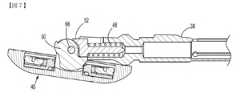
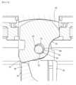
アンビルアセンブリ26は、同一出願人による米国特許第8,540,132号に開示されているアンビルアセンブリと共通の特徴を共有し、その内容全体は、参照により本明細書に組み込まれる。図3~5に最も良く示されるように、アンビルアセンブリ26は、アンビル中心ロッド38と、アンビル中心ロッド38に枢動可能に取り付けられたアンビルヘッド40とを含む。アンビルヘッド40は、図4および図6に示されるような第1の動作状態と、図7に示されるような第2の枢動状態または傾斜状態との間で枢動するように適合されている。アンビル中心ロッド38は、例えばピボットピン66などのピボット部材をそれを通して受容する横断方向の孔44を有する一対の遠位の離間したアーム42を含む。アンビルヘッド40は、ピボットピン66を介して遠位の離間したアーム42に枢動可能に連結されている。
アンビルアセンブリ26は、プランジャ46と、プランジャバネ48と、カムラッチまたはカムプレート50とをさらに含む。プランジャ46は、アンビル中心ロッド38内、例えば離間したアーム42間に少なくとも部分的に受容され、プランジャバネ48によって遠位方向にバネ付勢される。プランジャ46は、プランジャフィンガ52を含み、プランジャフィンガ52は、カムラッチ50に係合して遠位に配向された力をカムラッチ50に提供する。
アンビルヘッド40は、内部に凹部70を画定する筐体54と、筐体54の中心から近位に延在するポスト56とを含む。筐体54は、複数のステープル変形ポケット72を画定するアンビル組織接触表面58を有する。アンビルヘッド40のポスト56は、スロット62を画定する一対の離間したポストアーム60と、離間したポストアーム60を通って延在する横断方向の孔64とを含む。簡潔に上述されたように、アンビル中心ロッド38は、ポスト56の周囲に少なくとも部分的に位置付けられ、アンビル中心ロッド38およびポスト56の遠位の離間したアーム42の対応する横断方向の孔44、64を通って延在するピボット部材66を通してアンビルヘッド40に連結されて、アンビルヘッド40をアンビル中心ロッド38に枢動可能に連結する。加えて、カムラッチ50は、ポスト56のスロット62内に受容され、カムラッチ50のピン開口部68を通って延在するピボット部材66を介してアンビル中心ロッド38およびポスト56に連結される。
ここで図4~6を参照すると、アンビルアセンブリ26は、バックアップ部材76と、それに取り付けられたカットリング78とをさらに含む。バックアップ部材76およびカットリング78は、例えば器具10の発射中にツールアセンブリ16の環状ナイフ30が前進する間に、アンビルヘッド40に力を加えるとアンビルヘッド40の凹部70内で一緒に移動する。バックアップ部材76は、環状本体79と、環状本体79から半径方向に内向きに延在する一対の直径方向に対向するフィンガ98とを含む。バックアップ部材76の環状本体79は、軸方向に移動可能であるが、アンビルヘッド40の凹部70内に枢動可能に固定されている。 4-6,
フィンガ98は、アンビル中心ロッド38の離間したアーム42によって係合されて、バックアップ部材76が近位方向に移動するのを防止し、環状ナイフ30が作動されるまでアンビルヘッド40を動作状態(例えば、非傾斜)で維持する。より具体的には、図3に示されるように、バックアップ部材76が近位位置にあるとき、バックアップ部材76のフィンガ98は、アンビル中心ロッド38の離間したアーム42の遠位表面上に置かれるか、または当接し、それによってアンビルアセンブリ26に対するアンビルヘッド40の揺動または枢動が防止される。アンビル中心ロッド38に対するアンビルヘッド40の枢動は、フィンガ98がアンビル中心ロッド38のアーム42から遠位に離間した後にのみ可能である。
バックアップ部材76は、環状本体79から半径方向に内向きに延在する一対の直径方向に対向するカムシェルフ99をさらに含む。カムシェルフ99は、それらの間でカムラッチ50を捕捉して、カムラッチ50をバックアップ部材76に回転可能に固定する。このように、カムラッチ50が回転または枢動すると、バックアップ部材76およびアンビルヘッド40も全体として回転または枢動する。バックアップ部材76は、金属などの硬質材料から形成され得るが、他の構成材料も想定される。
アンビルアセンブリ26のカットリング78は、バックアップ部材76を受容するための中央開口106を画定するディスク形状の環状本体104を含む。したがって、非傾斜状態と傾斜状態との間のバックアップ部材76の移動は、カットリング78の対応する移動を引き起こす。実施形態では、カットリング78は、成形プロセス、例えば射出成形プロセスを通して形成されてもよく、環状ナイフ30が環状本体104を貫通し、バックアップ部材76に対して底部に達することを可能にするデュロメータを有する材料から製造されてもよい。カットリング78の好適な材料は、ポリプロピレンまたはポリエステルを含む。他の材料も企図される。 Cut
ステープリング機器10の発射前に、バックアップ部材76は、上記の方法でカットリング78がバックアップ部材76に固定された状態で、その格納位置または近位位置にある。バックアップ部材76が近位位置にあると、バックアップ部材76の内向きに延在するフィンガ98は、アンビル中心ロッド38の離間したアーム42(図4)によって係合され、これによりアンビルヘッド40は、動作状態で保持される。上記のように、アンビル中心ロッド38のプランジャ46のプランジャフィンガ52は、ピボット部材66の周囲でカムラッチ50およびアンビルヘッド40を傾斜状態に向けて付勢するように位置付けられる(図7)。しかしながら、アンビルヘッド40は、後述されるように、環状ナイフ30が前進して外科用アンビルアセンブリ26の係止アセンブリ100(図4、5、および8~12)を係止解除するまで枢動するのを防止される。 Prior to firing of stapling
図8~12を参照すると、外科用アンビルアセンブリ26は、第1の動作状態および第2の傾斜状態の各々でアンビルヘッド40を選択的に係止するための係止アセンブリ100をさらに含んでもよい。係止アセンブリ100は、米国特許第9,532,781号に記載されている保持具部材127などの従来技術の変形可能な保持具部材に取って代わり、その内容全体は、参照により本明細書に組み込まれる。変形可能な保持具部材は、典型的には、近位位置でバックアップ部材76を支持し、アンビルヘッド40の傾斜を可能にするためにバックアップ部材76の前進時に変形する。本実施形態では変形可能な保持具がないため、アンビルヘッド40は、非傾斜状態と傾斜状態との間で繰り返し移動することが可能である。 8-12,
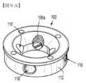
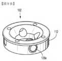
係止アセンブリ100は、概して、環状内側部材または筐体102と、内側部材102を包囲する環状外側部材104と、内側部材102に移動可能に連結された一対の係止要素106a、106bとを含む。実施形態では、内側部材102および外側部材104は、例えば、リング形状、正方形、三角形などの任意の好適な形状をとってもよい。内側部材102は、アンビルヘッド40の遠位に面する外側表面41上で固定して支持されている。アンビルヘッド40は、係止アセンブリ100の内側部材102をアンビルヘッド40に固定して取り付ける締結具(明示的には示されていない)を受容するために、それを通して画定された複数の穴108(図8)を有してもよい。内側部材102は、対応する係止要素106aまたは106bを収容するために、それを通して横断方向に画定された複数の通路110を画定する。4つの通路110が示されているが、内側部材102は、対応する数の係止要素106a、106bを収容するために4つより多いかまたは少ない通路110を有してもよいことが企図される。 Locking
係止要素106a、106bは、内側部材102の通路110内に受容され、互いに直径方向に反対に配置されている。係止要素106a、106bは、内側部材102の外周112から半径方向に外向きに突出するボール戻り止めであってもよい。実施形態では、係止要素106a、106bは、弾力的に、半径方向に外向きに付勢される任意の好適な付勢部材であってもよい。実施形態では、係止要素106a、106bが内側部材102に対して固定されたままであってもよい一方で、外側部材104は、可撓性であってもよく、後述されるように、これにより外側部材104が内側部材102に沿って摺動するにつれて、外側部材102が係止要素106a、106bに接触すると外向きに屈曲する。 Locking
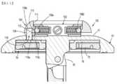
係止アセンブリ100の外側部材104は、内側部材102を包囲し、外側部材104がアンビルヘッド40の外側表面41と当接する第1の近位位置(図11)と、外側部材104がアンビルヘッド40の外側表面41から遠位に離間している第2の遠位位置(図12)との間で、長手方向軸「X」に沿って内側部材102に対して摺動可能である。外側部材104は、内側部材102の外周112に隣接し、かつそれを包囲する内側表面または内周114を有する。外側部材104の内周114は、係止要素106a、106bとの選択的相互作用のために、そこから半径方向に内向きに突出するリップまたはレッジ116を有する。
より具体的には、第1の近位位置(図11)では、外側部材104のリップ116は、係止要素106a、106bの外側表面の近位に配設されていると同時に、それと重なり合ってもいる。外側部材104のリップ116が係止要素106a、106bと重なっているため、係止要素106a、106bは、内側部材102に対する外側部材104の遠位の移動に抵抗する。係止アセンブリ100の外側部材104を遠位方向に移動させるために、遠位方向に配向された閾値力が、係止要素106a、106bのバネ力を克服するために外側部材104に加えられなければならない。閾値力が加えられると、係止要素106a、106bは、内側部材102に対して半径方向に内向きに移動し、外側部材104のリップ116が係止要素106a、106bを通り過ぎることを可能にする。 More specifically, in the first proximal position (FIG. 11), the
外側部材104が第2の遠位位置(図12)にあるとき、係止要素106a、106bおよび外側部材104のリップ116は、横軸に沿って係合および整合する。係止要素106a、106bが外向きに配向されたバネ付勢を示すため、外側部材104のリップ116および係止要素106a、106bは、互いと摩擦係合され、それによって閾値力が近位方向に加えられるまで、第2の遠位位置からの外側部材104の移動に抵抗する。 When
係止アセンブリ100は、係止アセンブリ100の内側部材102およびバックアップ部材76を相互接続する複数のポストまたはロッド118をさらに含む。ポスト118は、互いに円周方向に離間し、外側部材104から下向きに(例えば近位に)延在する。ポスト118は、外側部材104に取り付けられるか、または外側部材104と共に形成された遠位端118bと、アンビルヘッド40を通して画定された対応する穴108を通って延在する中間部分118cと、アンビルヘッド40の凹部70内に配設された近位端118aとを有する。ポスト118の各々の近位端118aは、外側部材104が内側部材102に対して移動すると、バックアップ部材76が外側部材104と共に移動するように、バックアップ部材76に固定される。したがって、外側部材104が第1の近位位置(図11)から第2の遠位位置(図12)に向かって移動すると、バックアップ部材76は、アンビルヘッド40の凹部70内へとより深く、かつアンビル中心ロッド38の遠位の離間したアーム42との係合から外れて移動する。 Locking
動作中、カットリング78を有するバックアップ部材76は、係止アセンブリ100によって近位位置で凹部70内に維持される。具体的には、係止要素106a、106bは、係止アセンブリ100の内側部材102に対する係止アセンブリ100の外側部材104の遠位の移動に抵抗する。バックアップ部材76は、係止アセンブリ100のポスト118を介して外側部材104に固定されるため、バックアップ部材76の遠位位置に向かう遠位の移動もまた抵抗される。 During operation,
アンビルヘッド40およびシェル24のステープルカートリッジ28(図3)が接近したとき、ステープリング機器10は、シェル24内の環状ナイフ30をシェル24内に引っ込んだ格納位置からアンビルアセンブリ26のカットリング78内へと延在する前進位置に前進させるために発射され得る。環状ナイフ30がカットリング78に係合すると、カットリング78およびバックアップ部材76は、係止アセンブリ118のポスト118を介して、係止アセンブリ100の外側部材104に、遠位に配向された力を及ぼす。閾値力を外側部材104に加えると、係止要素(複数可)106a、106bは、図11に示されるように、内側部材102の対応する通路110へと半径方向に内向きに押し込まれ、バックアップ部材76がアンビルヘッド40の凹部70内の第2の遠位位置に前進すると、外側部材104のリップ116が係止要素106a、106bを通り過ぎることを可能にする。いったんバックアップ部材76がその第2の位置に向かって移動すると、外側部材104のリップ116および係止要素106a、106bは、互いに摩擦係合して、外側部材104、次いでバックアップ部材76を第2の遠位位置に選択的に固定する。 When
バックアップ部材76がその遠位位置に向かって移動すると、バックアップ部材76のフィンガ98(図4および5)は、アンビル中心ロッド38の遠位の離間したアーム42を係合解除し、アンビル中心ロッド38に対してアンビルヘッド40を自由に枢動させる。アンビルヘッド40が自由に回転すると、プランジャバネ48(図6)は、プランジャ46を遠位方向に付勢し、それによってプランジャフィンガ52は、カムラッチ50に係合して、ピボット部材66を中心にしてカムラッチ50およびアンビルヘッド40を回転させて、アンビルヘッド40が図7に示される第2の傾斜状態をとることを可能にする。 As
アンビルヘッド40が傾斜状態に移動した後、アンビルヘッド40は、手動で第1の動作状態に向かって戻り得る。アンビルヘッド40が第1の動作状態(例えば、非傾斜)に戻った後、バックアップ部材76もまた、その近位位置にリセットされ得る。バックアップ部材76を近位位置に移動させるために、近位に配向された閾値力が、係止アセンブリ100の外側部材104に手動で加えられてもよく、それは、外側部材104のリップ116と係止要素106a、106bとの間の静摩擦を克服し、それによって外側部材104は、内側部材102に対して近位に移動する。ポスト118を介した外側部材104とバックアップ部材76との間の相互接続により、バックアップ部材76は、近位位置に向かって外側部材104と共に近位に戻る。 After
再び近位位置に入ると、バックアップ部材76のフィンガ98(図4および5)は、アンビル中心ロッド38の遠位の離間したアーム42と再係合し、それによりアンビルヘッド40を第1の動作状態に安定させる。アンビル中心ロッド38に対してアンビルヘッド40を選択的に移動させるこのプロセスは、無制限に繰り返され得ることが企図される。 Upon re-entering the proximal position, fingers 98 (FIGS. 4 and 5) of
図13~19を参照すると、上記のアンビルアセンブリ26と同様の外科用アンビルアセンブリ126の別の実施形態が示されている。本実施形態のアンビルアセンブリ126と上記のアンビルアセンブリ26との間の類似点により、アンビルアセンブリ26との相違点を明らかにするために必要と考えられるアンビルアセンブリ126の要素のみが詳細に説明される。 13-19, another embodiment of a
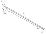
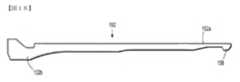
図13および14を具体的に参照すると、アンビルアセンブリ126は、アンビル中心ロッド138と、上記のアンビルヘッド40と同様のアンビルヘッド140とを含む。アンビルヘッド140は、アンビル中心ロッド138に枢動可能に取り付けられている。アンビル中心ロッド138は、一対の遠位の離間したアーム142と、一対の遠位の離間したアーム142から近位に延在する伸長された近位本体部分144とを含んでもよい。遠位の離間したアーム142は、上記のピボット部材66と同様のピボット部材(明示的には示されていない)を受容するための、その遠位端を通る横断方向の孔143を画定する。アンビル中心ロッド138の近位本体部分144は、例えば、図2に示されるアンビル保持具22などのアンビル保持具またはトロカールに解放可能に連結するように構成されている。アンビル保持具の詳細な説明は、米国特許第7,364,060号で見ることができ、その全内容は、参照により本明細書に組み込まれる。 13 and 14,
アンビル中心ロッド138の近位本体部分144は、一対の直径方向に対向するスロット150a、150bを画定する。スロット150a、150bは、遠位の離間したアーム142の近位端に隣接する位置から近位に延在し、近位本体部分144の近位端の遠位で終端する。スロット150a、150bは、後述されるように、アンビル保持具22をそれらの間に解放可能に捕捉するように構成された一対の脚部152、154を受容するように寸法決定されている。 The
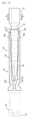
図15~19を参照すると、アンビル中心ロッド138の脚部152、154は、アンビル中心ロッド138の近位本体部分144の対応するスロット150a、150b内に受容される。脚部152、154の各々は、脚部152、154がその近位端152a、154aを中心にしてバネのように屈曲することを可能にする材料から製造される。脚部152、154の厚さは、それらの可撓性を調節するために増減され得ることが企図される。脚部152、154の遠位端152b、154bが、例えばレーザ溶接を介して近位本体部分144の内周156に取り付けられる一方で、脚部152、154の近位端152a、154aは、対応する遠位端152b、154bに対して自由に枢動する。 15-19, the
実施形態では、脚部152、154は、任意の好適な締結方法を使用して、脚部152、154の任意の好適な位置に沿って近位本体部分144に取り付けられてもよい。理解され得るように、脚部152、154が近位本体部分144に取り付けられる位置を調節することは、脚部152、154を屈曲させるために必要とされる力を変化させる。脚部152、154の近位端152a、154aは、半径方向に内向きに延在するタブまたは戻り止め158、160を含む。戻り止め158、160は、以下でさらに詳細に説明されるように、トロカール22の近位端によって画定されたリップ23とスナップ嵌め係合するように構成されている。 In embodiments,
脚部152、154の各々は、脚部152、154が近位本体部分144から外向きに突出しないように、近位本体部分144の外形と一致する外形を有する。脚部152、154の各々は、トロカール22の外形と実質的に一致する内形を有する。したがって、脚部152、154が近位本体部分144の対応するスロット150a、150b内に配設されると、脚部152、154は協働的に、トロカール22を受容するように寸法決定された空洞162をそれらの間に画定する。 Each of
製造中、脚部152、154は、近位本体部分144の対応するスロット150a、150b内に受容され、脚部152、154の各々の遠位端152b、154bは、近位本体部分144の内周156(図18)に溶接(例えば、レーザ溶接)される。図17および18に示されるように、トロカール22は、近位本体部分144を通って図18の矢印「A」によって示される方向に遠位に前進し、それによってトロカール22の基部の先細の外側表面25は、脚部152、154の近位端152a、154aにおいて戻り止め158、160と係合し、脚部152、154を外向きに屈曲させる。図19に示されるように、トロカール22の遠位の前進は、トロカール22の基部において画定されたリップ23が脚部152、154の戻り止め158、160を通り過ぎるまで続けられ、これにより戻り止め158、160は、トロカール22のリップ23の近位の所定位置に嵌り、脚部152、154の間に画定された空洞162内でトロカール22を捕捉する。脚部152、154の内向きに配向された弾性付勢は、近位本体部分144内でトロカール22を軸方向に固定する。 During manufacture,
図20~23を参照すると、上記のアンビルアセンブリと同様の外科用アンビルアセンブリ226の別の実施形態が示されている。本実施形態のアンビルアセンブリ226と上記のアンビルアセンブリとの間の類似点により、他のアンビルアセンブリとの相違点を明らかにするために必要と考えられるアンビルアセンブリ226の要素のみが詳細に説明される。 20-23, another embodiment of a
アンビルアセンブリ226は、アンビル中心ロッド238と、アンビル中心ロッド238に枢動可能に取り付けられたアンビルヘッド240と、アンビル中心ロッド238からアンビルヘッド240を選択的に係止解除するためのリングアセンブリ250とを含む。アンビルヘッド240は、第1の動作状態と第2の枢動状態または傾斜状態との間でアンビル中心ロッド238に対して枢動するように構成されている。アンビルヘッド240は、そこから近位に延在するアンビルヘッド240のポスト256を有する凹部270を内部に画定する。アンビルヘッド240のポスト256は、アンビル中心ロッド238の遠位端に枢動可能に連結されている。 The
リングアセンブリ250は、アンビルヘッド240内に画定された凹部270内に受容され、概して、バックアップ部材276と、バックアップ部材276の周囲に配置され、それに固定されたカットリング278とを含む。リングアセンブリ240は、例えば、環状ナイフ、例えば図3および6に示される環状ナイフ30などの前進中に、アンビルヘッド240に力を加えると、アンビルヘッド240の凹部270内で移動可能である。リングアセンブリ250のバックアップ部材276は、リング本体279と、その上でカットリング278を支持するためにリング本体279の遠位端から半径方向に外向きに延在する環状リップ252とを有する。リング本体279は、アンビルヘッド240のポスト256を受容するための中央開口294を画定する。中央開口294は、バックアップ部材276がアンビルヘッド40の凹部70内で、発射前の格納位置または近位位置(図20)から発射後の前進位置または遠位位置(図23)に、ポスト256の周囲で移動することを可能にするように寸法決定されている。
バックアップ部材276は、リング本体279から中央開口294内へと内向きに延在する一対の直径方向に対向するフィンガ298をさらに含む。フィンガ298は、アンビル中心ロッド238の遠位端によって係合されて、バックアップ部材276が近位方向に移動するのを防止し、上記と同様の方法でアンビルヘッド40を動作状態(例えば、非傾斜)で維持する。アンビル中心ロッド238に対するアンビルヘッド240の枢動は、フィンガ298がアンビル中心ロッド238の遠位端から遠位に離間した後にのみ可能である。後述されるように、バックアップ部材276は、カットリング278の脆弱部分254によって近位位置から外へと遠位に移動することを制限される。バックアップ部材276は、金属などの硬質材料から形成され得るが、他の構成材料も想定される。
リングアセンブリ250のカットリング278は、バックアップ部材276を受容するための中央開口258を画定するディスク形状の環状本体257を含む。環状本体257は、バックアップ部材276上に圧力嵌めされてもよい。したがって、近位位置と遠位位置との間のバックアップ部材276の移動は、カットリング278の対応する移動を引き起こす。実施形態では、カットリング278は、成形プロセス、例えば射出成形プロセスを通して形成されてもよく、環状ナイフ30が環状本体257を貫通し、バックアップ部材276の環状リップ252に対して底部に達することを可能にするデュロメータを有する材料から製造されてもよい。実施形態では、カットリング278は、環状ナイフ30がそれを通って前進するのを防止する材料から製造されてもよく、代わりに、環状ナイフ30がそれを通って前進することを可能にする材料でコーティングされる。カットリング278に好適な材料は、ポリテトラフルオロエチレン、ポリプロピレン、またはポリエステルを含む。他の材料も企図される。
図21に最も良く示されるように、カットリング278は、その底部または近位表面260に形成された複数のポケット258を含む。ポケット258は、湾曲形状を有するように示されているが、ポケット258が任意の好適な形状をとり得ることが企図される。カットリング278は、カットリング278の環状本体257の頂部または遠位表面262から遠位に延在する複数の脆弱部分または脚部254をさらに含む。図20に示されるように、脆弱脚部254は、アンビルヘッド240の凹部270内でカットリング278の環状本体257を吊るして、リングアセンブリ250を近位位置で維持する。脆弱脚部254は、湾曲形状を有してもよく、対応するポケット258の真上に位置付けられている。脆弱脚部254は、遠位に配向された閾値力をリングアセンブリ250に加えると、対応するポケット258内で変形する(例えば、崩壊する)ように構成されている。 As best shown in FIG. 21, cut
脆弱脚部254の変形を容易にするために、カットリング278の環状本体257の遠位表面262は、脆弱脚部254の両側に配設された一対の環状くぼみ264を画定する。くぼみ264は、弓状、V字形状、または任意の好適な断面構成を有し得る。カットリング278の脆弱脚部254は、カットリング278の環状本体257と同じか、または異なる材料から製造されてもよい。例えば、脆弱脚部254は、ポリテトラフルオロエチレン、ポリプロピレン、またはポリエステルから製造されてもよい。 To facilitate deformation of leg of
動作中、環状ナイフ30(図3および6)を発射する前は、リングアセンブリ250(バックアップ部材276とカットリング278とを含む)は、その格納位置または近位位置にある。近位位置では、カットリング278の脆弱脚部254は、アンビルヘッド240の内側表面272と係合しており、それにより図20に示されるように、リングアセンブリ250を近位位置で維持する。リングアセンブリ250が近位位置にあると、バックアップ部材276の内向きに延在するフィンガ298は、アンビル中心ロッド238によって係合され、これによりアンビルヘッド240は、第1の動作状態で保持され、アンビル中心ロッド238に対して枢動するのを防止される。 In operation, prior to firing annular knife 30 (FIGS. 3 and 6), ring assembly 250 (including
環状ナイフ30(図3および6)が前進すると、環状ナイフ30は、リングアセンブリ250のカットリング278の環状本体257に係合する。環状ナイフ30は、カットリング278の環状本体257を貫通し、最終的にバックアップ部材276の環状リップ252に係合する。環状ナイフ30によってリングアセンブリ250に加えられた力は、カットリング278の環状本体257に伝達され、それは、カットリング278の脆弱脚部254とアンビルヘッド240の内側表面272との間で圧縮される。環状ナイフ30が遠位に配向された閾値力をリングアセンブリ250に加えると、カットリング278の脆弱脚部254は、環状くぼみ264に沿ってカットリング278の環状本体257から切り離されるか、または裂ける。 As annular knife 30 ( FIGS. 3 and 6 ) is advanced,
カットリング278の脆弱脚部254がカットリング278の環状本体257から切り離されると、環状ナイフ30を介してリングアセンブリ250に継続的に加えられる遠位に配向された力は、カットリング278の環状本体257およびバックアップ部材276を遠位に駆動し、それによって図23に示されるように、カットリング278の脆弱脚部254は、カットリング278の環状本体257内の対応するポケット258内へと崩壊するか、または入る。リングアセンブリ250が遠位位置に向かって前進すると、バックアップ部材276の内向きに延在するフィンガ298は、アンビル中心ロッド238のアームから係合解除し、アンビルヘッド240がアンビル中心ロッド238に対して枢動することを可能にする。アンビルヘッド240は、上記と同じ方法でアンビル中心ロッド238に対して自動で枢動し得ることが企図される。実施形態では、アンビルヘッド240は、参照により本明細書に組み込まれる特許に記載されている機構など、任意の好適な機構を介して自動または手動で枢動し得る。 Once the weakened
図24~29を参照すると、上記の外科用アンビルアセンブリと同様の外科用アンビルアセンブリ326の別の実施形態が示されている。本実施形態のアンビルアセンブリ326と上記のアンビルアセンブリとの間の類似点により、すでに記載されたアンビルアセンブリとの相違点を明らかにするために必要と考えられるアンビルアセンブリ326の要素のみが詳細に説明される。 24-29, another embodiment of a
アンビルアセンブリ326は、概して、上記のアンビル中心ロッドと同様のアンビル中心ロッド(図示せず)と、アンビル中心ロッドに枢動可能に取り付けられるように構成されたアンビルヘッド340と、アンビル中心ロッドからアンビルヘッド340を選択的に係止解除するように構成されたリングアセンブリ350とを含む。アンビルヘッド340は、第1の動作状態と第2の枢動状態または傾斜状態との間でアンビル中心ロッドに対して枢動するように構成されている。
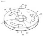
アンビルヘッド340は、そこから近位に延在するアンビルヘッド340のポスト356を有する凹部370(図28)を内部に画定する。アンビルヘッド340のポスト356は、アンビル中心ロッドの遠位端に枢動可能に連結されるように構成されている。アンビルヘッド340の凹部370は、リングアセンブリ350を摺動可能に受容するように寸法決定されている。アンビルヘッド340は、凹部370を部分的に画定する環状の内周表面372と、内周表面372から半径方向に内向きに延在する内側レースまたはキャッチ374とを含む。内側レース374は、防止することなく、アンビルヘッド340の凹部370を通るリングアセンブリ350の遠位の移動に抵抗する。
リングアセンブリ350は、概して、上記のバックアップ部材と同様のバックアップ部材376と、バックアップ部材376内に入れ子になったリングカップ352と、リングカップ352内に入れ子になったカットリング378とを含む。リングアセンブリ350は、例えば、環状ナイフ30(図28および29)の前進中に、アンビルヘッド340に力を加えると、アンビルヘッド340の凹部370内で移動する。バックアップ部材376は、アンビルヘッド340のポスト356を受容するための中央開口394を画定する。中央開口394は、バックアップ部材376がアンビルヘッド340の凹部370内で、発射前の格納位置または第1の位置から発射後の前進位置または第2の位置に、ポスト356の周囲で移動することを容易にするように寸法決定されている。バックアップ部材376は、後述されるように、近位位置(図28)でリングカップ352を支持するアンビルヘッド340の内側レース374によって、近位位置で保持される。
バックアップ部材376は、中央開口394内へと内向きに延在する一対の直径方向に対向するフィンガ398を含む。フィンガ398は、アンビル中心ロッドによって係合されて、バックアップ部材376が近位方向に移動するのを防止し、アンビルヘッド340を動作状態(例えば、非傾斜)で維持する。アンビル中心ロッドに対するアンビルヘッド340の枢動は、フィンガ398がアンビル中心ロッドから遠位に離間した後にのみ可能である。
リングアセンブリ350のバックアップ部材376は、環状壁またはリング354と、環状壁354の遠位部分から半径方向に外向きに延在するディスク形状のプラットフォーム357とをさらに含む。環状壁354は、その近位部分から半径方向に内向きに延在するリップ358を有する。リップ358は、(例えば、スナップ嵌め係合を介して)リングカップ352に係合して、リングカップ352をバックアップ部材376と保持するように構成されている。バックアップ部材376は、金属などの硬質材料から形成され得るが、他の構成材料も想定される。
リングアセンブリ350のリングカップ352は、カットリング378をその中で支持し、環状ナイフ30をカットリング378内へと誘導して、カットリング378の部分的切断またはオフセット切断を防止する。リングカップ352は、アンビルヘッド340の内周表面372とバックアップ部材376との間に捕捉されることによって、バックアップ部材376と入れ子になっている。リングカップ352は、概して、環状外壁360と、環状の第1の内壁362と、外壁360および第1の内壁362を相互接続するディスク形状の基部364とを含む。外壁360、基部364、および第1の内壁362は協働的に、カットリング352を受容するように寸法決定された空洞または環状チャンバ366を画定する。 A
図24~27に最も良く示されるように、リングカップ352の外壁360は、環状の外周表面360aと環状の内周表面360bとを有し、環状壁360の厚さは、それらの間に画定されている。外側リップ368は、外壁360の外周表面360aから半径方向に外向きに延在する。外壁360の外側リップ368は、アンビルヘッド340の内側レース374と重なって、近位位置でリングアセンブリ350を支持し、遠位位置に向かうリングアセンブリ350の移動に抵抗する。 As best shown in FIGS. 24-27, the
外壁360は、内部に画定された複数のスリット380を有してもよい。スリットは、外壁360の周囲で円周方向に配置されている。スリット380は、外壁360を可撓性にし、これによりリングアセンブリ350がアンビルヘッド340の凹部370を通って遠位に前進すると、外壁360は、半径方向に内向きに屈曲するか、または曲がって、アンビルヘッド340の内側レース374の下の所定位置に嵌ることができる。実施形態では、スリット380を有する代わりに、またはそれに加えて、外壁360は、アンビルヘッド340への組み立て中に外壁360の半径方向の収縮を容易にするために可撓性材料から製造されてもよい。
リングカップ352の外壁360は、外壁360の最近位表面から下向きに(例えば、遠位に)傾斜する面取り表面382をさらに含む。面取り表面382の環状内縁部384(図27)は、外壁360の内周表面360bの半径方向に内向きに配設され、これにより面取り表面382は、アンダーカットまたはオーバーハング386を画定する。アンダーカット386は、カットリング378の外縁部388を覆い、リングカップ352の環状チャンバ366内でカットリング378を捕捉する。したがって、環状ナイフ30が前進すると、面取り表面382は、カットリング378の外縁部388の半径方向に内向きの位置で、内向きに、かつカットリング378と接触するようにナイフ30を誘導または方向転換する。これにより、ライン間のステープリング状態の可能性が排除される。
ナイフ30がカットリング378と接触する位置は、アンダーカット386の深さを調節することによって調節され得ることが企図される。例えば、ナイフ30がより半径方向に内向きの位置でカットリング378と接触することを確実にするために、外壁360におけるアンダーカット386の深さは、増加し得る。アンダーカット386の深さを増加させることに加えて、またはその代わりに、面取り表面382の環状内縁部384は、外壁360の内周表面360bに対して半径方向に内向きにより大きい距離延在して、ナイフ30をより半径方向に内向きの位置でカットリング378に接触させる。 It is contemplated that the location where
リングカップ352は、第1の内壁362の半径方向に内向きに配設された環状の第2の内壁390をさらに含む。第2の内壁390は、第2の内壁390が第1の内壁362に対して屈曲することを可能にする複数のブリッジ部材392を介して、第1の内壁362に連結されてもよい。第2の内壁390はまた、内部に画定された複数のスリット395を含んでもよい。スリット395は、第2の内壁390の屈曲をさらに容易にするために、第2の内壁390の周囲で円周方向に配置されている。リングカップ352をバックアップ部材376に組み立てるために、リングカップ352の第2の内壁390は、半径方向に内向きに屈曲し、バックアップ部材376のリップ358の下で捕捉される。
リングアセンブリ350のカットリング378は、リングカップ352の外壁360とリングカップ352の第1の内壁362との間で、リングカップ352の環状チャンバ366内に受容される。カットリング378の外縁部388は、リングカップ352の面取り表面382のアンダーカット386の下に配設されている。カットリング378は、リングカップ352上に圧力嵌めされ得ることが企図される。したがって、近位位置と遠位位置との間のリングカップ352の移動は、カットリング378の対応する移動を引き起こす。実施形態では、カットリング378は、成形プロセス、例えば射出成形プロセスを通して形成され、リングカップ352の基部部分364を通って画定された複数の穴397(図26)を通って延在し得る。
カットリング378は、環状ナイフ30がカットリング378を貫通し、リングカップ352の基部部分364に対して底部に達することを可能にするデュロメータを有する材料から製造されてもよい。したがって、リングカップ352の全部またはその選択部分(例えば、面取り表面382および基部部分364)は、カットリング378よりも硬質な材料から製造される。カットリング378に好適な材料は、ポリテトラフルオロエチレン、ポリプロピレン、またはポリエステルを含む。他の材料も企図される。
動作中、本実施形態の外科用アンビルアセンブリ326を有する円形ステープリング機器を発射する前に、バックアップ部材376と、リングカップ352と、カットリング378とを含むリングアセンブリ350は、図28に示されるように、その格納位置または近位位置にある。リングカップ352の外壁360の外側リップ368は、アンビルヘッド340の内側レース374と重なって、リングアセンブリ350を近位位置で支持する。リングアセンブリ350が近位位置にあると、バックアップ部材376の内向きに延在するフィンガ398は、アンビル中心ロッドによって係合されて、上記のように第1の動作状態でアンビルヘッド340を維持する。 In operation, prior to firing a circular stapling instrument with
ステープリング機器が作動すると、環状ナイフ30は、リングアセンブリ350のカットリング378と係合するように前進する。場合によっては、環状ナイフ30の一セクションは、カットリング378との垂直の位置合わせから外れていてもよい(例えば、半径方向に外向きに配設されている)。これらの例では、ナイフ30が前進すると、ナイフ30は、リングカップ352の面取り表面382に係合し、それは、ナイフ30を半径方向に内向きに、カットリング378と垂直に位置合わせされるように方向付ける。リングカップ352の面取り表面382がカットリング378上に張り出しているため、ナイフ30は、カットリング378の外縁部388の半径方向に内向きにカットリング378と接触する。 When the stapling instrument is actuated,
ナイフ30の前進が続けられると、ナイフ30は、図29に示されるように、カットリング378を貫通し、最終的にリングカップ352の基部部分364に係合する。ナイフ30によって加えられた力は、リングカップ352の外壁360を内向きに屈曲させるか、または曲げて、アンビルヘッド340の内側レース374を通り過ぎる。リングカップ352は、次いで、カットリング378およびバックアップ部材376と共に、遠位位置に向かって遠位に駆動される。 As the advancement of
リングアセンブリ350が遠位位置に向かって前進すると、バックアップ部材378の内向きに延在するフィンガ398は、アンビル中心ロッドを係合解除し、アンビルヘッド340がアンビル中心ロッドに対して枢動することを可能にする。アンビルヘッド340は、本明細書に記載される任意の方法でアンビル中心ロッドに対して自動で枢動するように構成され得ることが企図される。実施形態では、アンビルヘッド340は、それが自動か手動かにかかわらず、任意の好適な枢動機構を介して枢動し得る。 As
図30~32を参照すると、上記のアンビルアセンブリと同様の外科用アンビルアセンブリ426の別の実施形態が示されている。本実施形態のアンビルアセンブリ426と上記のアンビルアセンブリとの間の類似点により、上記のアンビルアセンブリとの相違点を明らかにするために必要と考えられるアンビルアセンブリ426の要素のみが詳細に説明される。 30-32, another embodiment of a
アンビルアセンブリ426は、概して、上記のアンビル中心ロッドと同様のアンビル中心ロッド(図示せず)と、アンビル中心ロッドに枢動可能に取り付けられたアンビルヘッド440と、アンビル中心ロッドからアンビルヘッド440を選択的に係止解除するように構成されたリングアセンブリ450とを含む。アンビルヘッド440は、第1の動作状態と第2の枢動状態または傾斜状態との間でアンビル中心ロッドに対して枢動するように構成されている。アンビルヘッド440は、リングアセンブリ450を受容するための凹部470を内部に画定する。アンビルヘッド440は、凹部470を部分的に画定する環状内周表面472を含む。 The
アンビルヘッド440は、米国特許第9,532,781号に記載されている保持具部材127と同様の脆弱保持具部材(図示せず)を含んでもよく、その内容全体は、参照により本明細書に組み込まれる。脆弱保持具部材は、アンビルヘッド440の内周表面472とリングアセンブリ450との間で、アンビルヘッド440の凹部470内に配設されてもよく、これによりリングアセンブリ450に閾値遠位力が加えられると、脆弱保持具部材は崩壊し、リングアセンブリ450および環状ナイフ30の遠位の前進を可能にする。
リングアセンブリ440は、アンビルヘッド440内に画定された凹部470内に受容され、概して、バックアップ部材476と、バックアップ部材476内に入れ子になった第1のカットリング452と、第1のカットリング452内に入れ子になった第2のカットリング478とを含む。リングアセンブリ450は、例えば環状ナイフ30の前進中に、アンビルヘッド440に力を加えると、アンビルヘッド440の凹部470内で移動する。
バックアップ部材476は、アンビルヘッド440のポスト456を受容するための中央開口494を画定する。中央開口494は、バックアップ部材476がアンビルヘッド440の凹部470内で、発射前の格納位置または第1の位置から発射後の前進位置または第2の位置に、ポスト456の周囲で移動することを容易にするように寸法決定されている。バックアップ部材476は、上記のバックアップ部材と同様に、中央開口494内へと内向きに延在する一対の直径方向に対向するフィンガ(明示的には示されていない)を含む。フィンガは、アンビル中心ロッドによって係合されて、バックアップ部材476が近位方向に移動するのを防止し、アンビルヘッド440を動作状態(例えば、非傾斜)で維持する。アンビル中心ロッドに対するアンビルヘッド440の枢動は、バックアップ部材476のフィンガが、上ですでに記載されたようにアンビル中心ロッドから遠位に離間した後にのみ可能である。
バックアップ部材476は、環状壁またはリング454と、環状壁454の遠位部分から半径方向に外向きに延在するディスク形状のプラットフォーム457とをさらに含む。環状壁454は、その近位部分から半径方向に内向きに延在するリップ458を有する。リップ458は、(例えばスナップ嵌め係合を介して)第1のカットリング452に係合して、第1のカットリング452をバックアップ部材476と保持するように構成されている。バックアップ部材476は、金属などの硬質材料から形成され得るが、他の構成材料も想定される。
リングアセンブリ450の第1のカットリング452は、第2のカットリング476を内部で支持し、ステープルが切断されるべき表面を提供する。第1のカットリング452は、環状ナイフ30によって貫通されることに抵抗する、例えば硬質プラスチックなどの第1の材料から製造される。第1のカットリング452は、アンビルヘッド440の内周表面472とバックアップ部材476との間に捕捉されることによって、バックアップ部材476と入れ子になっている。第1のカットリング452は、近位部分452aと、遠位部分452bと、それらの間に配設された環状カットアウトまたは凹部452cとを含む。環状凹部452cは、第1のカットリング452の外周表面460内に画定され、第2のカットリング478を内部に捕捉する。 A
第1のカットリング452は、その近位部分452aにおいて、第1のカットリング452の近位表面464に沿って円周方向に延在する環状溝462をさらに画定する。溝462は、V字形状の構成を有するように示されているが、溝462は、例えばU字形状または正方形などの任意の好適な構成をとってもよいことが企図される。溝462は、第1のカットリング452の環状凹部452cと垂直に位置合わせされ、溝462の頂点466に向かって半径方向に内向きに環状ナイフ30(図32)を誘導するように構成されている。 The
第1のカットリング452の近位部分452aは、溝462の頂点466と環状凹部452cとの間に画定された減少した厚さを有する。したがって、環状ナイフ30が第1のカットリング452の近位部分452a内へと遠位に前進すると、環状ナイフ30は、第1のカットリング452の溝462を通る垂直経路「P」に沿って、第1のカットリング452の近位部分452aを切り開く。溝462の深さは、環状ナイフ30が切り開くのに必要な力を増大させるために増加し得るか、または環状ナイフ30が切り開くのに必要な力を減少させるために減少し得る。 The
リングアセンブリ450の第2のカットリング478は、第1のカットリング452の環状凹部452c内に受容される。上記のように、第2のカットリング478は、第1のカットリング452の溝462と垂直方向に位置合わせされ、これにより第1のカットリング452の溝462は、第2のカットリング478の外周表面の半径方向に内向きの位置で、第2のカットリング478内へと環状ナイフ30を誘導する。第2のカットリング478は、第1のカットリング452の環状凹部452cに圧力嵌めされ得ることが企図される。したがって、近位位置と遠位位置との間の第1のカットリング452の移動は、第2のカットリング478の対応する移動を引き起こす。比較的硬質な第1のカットリング452は、組織をきれいに切断するために使用される比較的軟質な第2のカットリング478に引き込まれることなく、環状ナイフ30がステープルを切り開くことができる表面を提供する。
実施形態では、第2のカットリング478は、成形プロセス、例えば射出成形プロセスを通して形成されてもよい。第2のカットリング478は、環状ナイフ30が第2のカットリング478を貫通し、第1のカットリング452bの遠位部分452bに対して底部に達することを可能にするデュロメータを有する材料から製造されてもよい。したがって、第2のカットリング478は、第1のカットリング452よりも軟質な材料から製造される。第2のカットリング478に好適な材料は、ポリテトラフルオロエチレン、ポリプロピレン、またはポリエステルを含む。他の材料も企図される。 In embodiments, the
動作中、本実施形態の外科用アンビルアセンブリ426を有する円形ステープリング機器を発射する前に、バックアップ部材476と、第1のカットリング452と、第2のカットリング478とを含むリングアセンブリ450は、その格納位置または近位位置にある。脆弱保持具部材(明示的には示されていない)は、バックアップ部材476とアンビルヘッド440の内側表面472との間に挿入されて、近位位置でリングアセンブリ450を支持する。リングアセンブリ450が近位位置にあると、バックアップ部材476の内向きに延在するフィンガは、アンビル中心ロッドによって係合され、これによりアンビルヘッド440は、第1の動作状態で保持される。 In operation, prior to firing a circular stapling instrument with
ステープリング機器が作動すると、環状ナイフ30は、第1のカットリング452の溝462を画定する傾斜表面462a、462b(図31)と係合するように前進する。傾斜表面462a、462bは、第2のカットリング478の中央部分と垂直に位置合わせされるように、半径方向に内向きにナイフ30を方向付ける。環状ナイフ30は、溝462を通って移動し、溝462の頂点466と接触し、遠位に配向された力を脆弱保持具部材に伝達する。脆弱保持具部材に閾値力を加えると、脆弱保持具部材は崩壊し、アンビルヘッド440の凹部470を通るリングアセンブリ450の遠位の移動を可能にする。 When the stapling instrument is actuated, the
リングアセンブリ450が遠位位置に向かって前進すると、バックアップ部材476の内向きに延在するフィンガは、アンビル中心ロッドから係合解除し、アンビルヘッド440がアンビル中心ロッドに対して枢動することを可能にする。アンビルヘッド440は、本明細書に記載される任意の方法でアンビル中心ロッドに対して自動で枢動するように構成され得ることが企図される。実施形態では、アンビルヘッド440は、それが自動か手動かにかかわらず、任意の好適な枢動機構を介して枢動し得る。 As
環状ナイフ30の前進が続けられると、環状ナイフ30は、第1のカットリング452の近位部分452aを切り開き、その経路に沿って任意の組織およびステープルを切り進み、第1のカットリング452の近位部分452aの残りから、第1のカットリング452の近位部分452aの外周セクションを切り離す。第1のカットリング452の外周セクションは、摩擦を介して環状ナイフ30の外側表面に接着したままであることが企図される。環状ナイフ30の前進が続けられると、環状ナイフ30は、第2のカットリング478を切り開き、最終的に第1のカットリング452の遠位部分452b上で底部に達する。実施形態では、脆弱保持具部材は、環状ナイフ30が第1のカットリング452の近位部分452aを切り開く前よりもむしろ後に崩壊するように構成されてもよい。 As the advancement of
図33~40を参照すると、上記のアンビルアセンブリと同様の外科用アンビルアセンブリ526の別の実施形態が示されている。本実施形態のアンビルアセンブリ526と上記のアンビルアセンブリとの間の類似点により、上記のアンビルアセンブリとの相違点を明らかにするために必要と考えられるアンビルアセンブリ526の要素のみが詳細に説明される。 33-40, another embodiment of a
図33および34を参照すると、アンビルアセンブリ526は、概して、上記のアンビル中心ロッドと同様のアンビル中心ロッド(図示せず)と、アンビル中心ロッドに枢動可能に取り付けられたアンビルヘッド540と、アンビル中心ロッドからアンビルヘッド540を選択的に係止解除するように構成されたリングアセンブリ550とを含む。アンビルヘッド540は、第1の動作状態と第2の枢動状態または傾斜状態との間でアンビル中心ロッドに対して枢動するように構成されている。 33 and 34,
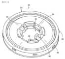
アンビルヘッド540は、リングアセンブリ550を受容するように寸法決定された凹部570を内部に画定する。アンビルヘッド540は、凹部570内の中央に位置し、凹部570の床部から近位に突出するポスト556を含む。ポスト556は、アンビルヘッド540をアンビル中心ロッドに枢動可能に連結する。例えば、アンビルヘッド540のポスト556は、アンビル中心ロッドの一対の遠位の離間したアームに枢動可能に連結されてもよい。ポスト556は、そこから半径方向に外向きに突出する環状レッジ524を有する本体522を有する。環状レッジ524は、リングアセンブリ550を発射前の近位位置で選択的に維持するように構成されている。ポスト556の本体522は、環状レッジ524の下または遠位に配設された環状陥凹部526を画定する。
リングアセンブリ550は、アンビルヘッド540内に画定された凹部570内に受容され、概して、ポスト556の本体522に係合されたスナップカラー552と、スナップカラー552上で支持されたバックアップ部材576と、スナップカラー552とバックアップ部材576との間に捕捉されたカットリング578とを含む。リングアセンブリ550は、例えば、環状ナイフ、例えば環状ナイフ30(図3および6)などの前進中に、凹部570に力を加えると、凹部570内で移動する。 The
図35~37を具体的に参照すると、リングアセンブリ550のスナップカラー552は、リングアセンブリ550を近位位置で選択的に維持するが、遠位に配向された閾値力をリングアセンブリ550に加えると、リングアセンブリ550が遠位位置に向かって移動することを可能にするように構成されている。スナップカラー552は、モノリシックに形成されたプラスチック片であってもよいか、または複数の接続された構成要素から構成されてもよい。スナップカラー552は、複数の水平に延在する支持表面またはフランジ554と、対応する隣接対のフランジ554間に挿入された複数の垂直延在部558とを含む。したがって、フランジ554および垂直延在部558は、スナップカラー552の円周の周囲に交互に配置されている。スナップカラー552は、互いに対して90°離間して、スナップカラー552の周囲で円周方向に配置された4つのフランジ554を含んでもよい。同様に、スナップカラー552は、互いに対して90°離間して、スナップカラー552の周囲で円周方向に配置された4つの垂直延在部558を含んでもよい。スナップカラー552は、4つより多いまたは少ないフランジ554および垂直延在部558を有し得ることが企図される。 With specific reference to FIGS. 35-37,
スナップカラー552のフランジ554は、平坦であり、その上にバックアップ部材576(図36)を支持してもよく、これによりバックアップ部材576の遠位の移動は、スナップカラー552の遠位の移動を引き起こす。スナップカラー552の垂直延在部558は、フランジ554に対して垂直な角度で近位に延在してもよい。垂直延在部558は各々、そこから半径方向に内向きに延在する環状内側リップ560と、そこから半径方向に外向きに延在する環状外側リップ562とを含む。環状内側リップ560は、リングアセンブリ550が近位位置にあるときに、アンビルヘッド540のポスト556の環状レッジ524上で支持される。スナップカラー552の環状内側リップ560は、遠位に配向された閾値力が垂直延在部558の外側の屈曲を引き起こし、それがアンビルヘッド540のポスト556の環状レッジ524からスナップカラー552の環状内側リップ560を係合解除するまで、遠位位置に向かうリングアセンブリ550の移動に抵抗する。スナップカラー552の環状外側リップ562は、カットリング578の近位表面を覆って、カットリング578がスナップカラー552に対して移動するのを防止する。
図35、36、38A、および38Bを参照すると、バックアップ部材576は、中央開口部594を画定するリング本体580と、環状本体594から中央開口部594内へと半径方向に内向きに延在する一対の直径方向に対向するタブ582と、中央開口部594内へと内向きに延在する一対の直径方向に対向するフィンガ598とを含む。中央開口部594は、アンビルヘッド540のポスト556を受容し、バックアップ部材576がアンビルヘッド540の凹部570内で、発射前の格納位置または第1の位置から発射後の前進位置または第2の位置に、ポスト556の周囲で移動することを容易にするように寸法決定されている。バックアップ部材576は、スナップカラー552がポスト556の環状レッジ524と係合することによって近位位置で保持される。 35, 36, 38A and 38B, the
バックアップ部材576のタブ582は、スナップカラー552の直径方向に対向するフランジ554の第1の対上で支持されている。バックアップ部材576のタブ582は、環状ナイフ30の前進によって加えられる遠位に配向された力をスナップカラー552に伝達するように構成されている。バックアップ部材576のフィンガ598は、リング本体580から、バックアップ部材576のタブ582よりもさらに遠くまで半径方向に内向きに延在し、ポスト556の本体522内のカットアウト528内に受容される。バックアップ部材576のフィンガ598は、バックアップ部材576のリング本体580から水平方向に延在する第1の部分598aと、第1の部分598aから垂直方向に上向きまたは近位に延在する第2の部分598bとを有する。フィンガ598の各々の第1の部分598aは、スナップカラー552の直径方向に対向するフランジ554の第2の対上で支持されている。
フィンガ598の第2の部分598bは、アンビル中心ロッドによって係合されて、バックアップ部材576が近位方向に移動するのを防止し、アンビルヘッド540を動作状態(例えば、非傾斜)で維持する。アンビル中心ロッドに対するアンビルヘッド540の枢動は、バックアップ部材576のフィンガ598が、アンビル中心ロッドから遠位に離間した後にのみ可能である。バックアップ部材576は、金属などの硬質材料から打ち抜かれ得るが、他の構成材料も想定される。 A
図33、35、36、39、および40を参照すると、リングアセンブリ550のカットリング578は、バックアップ部材576上で支持され、スナップカラー552の環状外側リップ562とバックアップ部材576のタブ582およびフィンガ598との間に捕捉される内周表面590を有する。したがって、バックアップ部材576の近位または遠位の移動は、スナップカラー552およびカットリング578の対応する近位または遠位の移動をもたらす。カットリング578は、その外周表面から突出する複数の表面特徴596を有する。表面特徴596は、アンビルヘッド540の内側レース574の下に圧力嵌めされて、リングアセンブリ550を凹部570内で保持する。 33, 35, 36, 39, and 40, the
カットリング578は、環状ナイフ30がカットリング578を貫通し、バックアップ部材576のリング本体580に対して底部に達することを可能にするデュロメータを有する材料から製造されてもよい。したがって、バックアップ部材576は、カットリング578よりも硬質な材料から製造され得る。カットリング578に好適な材料は、ポリテトラフルオロエチレン、ポリプロピレン、またはポリエステルを含む。他の材料も企図される。
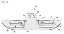
動作中、本実施形態の外科用アンビルアセンブリ526を有する円形ステープリング機器の発射前に、バックアップ部材576と、スナップカラー552と、カットリング578とを含むリングアセンブリ550は、図39に示されるように、アンビルヘッド540の凹部570内のその格納位置または近位位置にある。スナップカラー552の環状内側リップ560は、アンビルヘッド540のポスト556の環状レッジ524上で支持され、カットリング578の表面特徴596は、アンビルヘッド540の内側レース574上で支持されている。リングアセンブリ550が近位位置にあると、バックアップ部材576の内向きに延在するフィンガ598は、アンビル中心ロッドによって係合され、これによりアンビルヘッド540は、第1の動作状態で保持される。 In operation, prior to firing a circular stapling instrument with
ステープリング機器が作動すると、環状ナイフは、リングアセンブリ550のカットリング578と係合するように前進し、それは、遠位に配向された力をバックアップ部材576に伝達し、次いで遠位に配向された力をスナップカラー552に伝達する。閾値力を達成すると、スナップカラー552の垂直延在部558は、外向きに屈曲して、スナップカラー552の環状内側リップ560をアンビルヘッド540のポスト556の環状レッジ524から分離する。 When the stapling instrument is actuated, the annular knife advances into engagement with
スナップカラー552の環状内側リップ560がアンビルヘッド540のポスト556の環状レッジ524との重なり合った係合から外れると、環状ナイフによって付与された遠位に配向された力がリングアセンブリ550を遠位に駆動し、それによってバックアップ部材576は、アンビルヘッド540の内面572に接触し、スナップリング552の環状内側リップ560は、図40に示されるように、アンビルヘッド540のポスト556の陥凹部526内に受容される。環状ナイフの前進が続けられると、環状ナイフは、カットリング578を貫通し、最終的にはバックアップ部材576のリング本体580に対して底部に達する。 When annular
実施形態では、カットリング578およびスナップカラー552は、スナップカラー552を移動させてアンビルヘッド554のポスト556の環状レッジ524との係合から外す前に、環状ナイフがカットリング578を切り開くように構成されてもよい。 In an embodiment, cut
リングアセンブリ550が遠位位置に向かって前進すると、バックアップ部材576の内向きに延在するフィンガ598は、アンビル中心ロッドのアームから係合解除し、アンビルヘッド540がアンビル中心ロッドに対して枢動することを可能にする。アンビルヘッド540は、本明細書に記載される任意の方法でアンビル中心ロッドに対して自動で枢動するように構成され得ることが企図される。実施形態では、アンビルヘッド540は、それが自動か手動かにかかわらず、任意の好適な枢動機構を介して枢動し得る。 As
図41~44を参照すると、上記のアンビルアセンブリと同様の外科用アンビルアセンブリ626の別の実施形態が示されている。本実施形態のアンビルアセンブリ626と上記のアンビルアセンブリとの間の類似点により、上記のアンビルアセンブリとの相違点を明らかにするために必要と考えられるアンビルアセンブリ626の要素のみが詳細に説明される。 41-44, another embodiment of a
アンビルアセンブリ626は、アンビル中心ロッド638と、アンビル中心ロッド638に枢動可能に取り付けられたアンビルヘッド640とを含む。アンビルヘッド640は、図41に示されるような第1の動作状態と、図44に示されるような第2の枢動状態または傾斜状態との間で枢動するように適合されている。アンビルヘッド640は、ポスト656とアンビル組織接触表面658とを有する筐体654を含む。ポスト656は、離間したポストアームを通って延在する横断方向の孔664を画定する一対の離間したポストアームを含んでもよい。アンビル中心ロッド638は、ポスト656の周囲に少なくとも部分的に位置付けられ、ピボット部材666を通してアンビルヘッド640に連結されている。
アンビル中心ロッド638は、一対の直径方向に対向し、長手方向に延在するスロット662を画定する一対の遠位の離間したアーム642を含んでもよい。遠位の離間したアーム642は、アンビルヘッド640のポスト656をアンビル中心ロッド638の遠位の離間したアーム642に枢動可能に連結するピボット部材666を受容するための横断芳香の孔644が画定される遠位端を含む。枢動部材666は、アンビルヘッド640のポスト656の第1の位置「L1」に連結され、それは、アンビル中心ロッド638によって画定された中心長手方向軸「X」と整合している。
アンビルアセンブリ626は、アンビルヘッド640の傾斜を駆動するための従来のプランジャおよびカムラッチアセンブリに代わる枢動アセンブリ600をさらに含む。枢動アセンブリ600は、アンビル中心ロッド638内、例えば離間したアーム642間に少なくとも部分的に受容され、例えばコイルバネなどの付勢部材602によって近位方向にバネ付勢される。枢動アセンブリ600は、アンビル中心ロッド638の遠位の離間したアーム642のスロット662のうちの1つに受容されるリンケージアーム604を含む。リンケージアーム604は、L字形状の構成を有し、伸長シャフト606と、シャフト606の近位端606aから垂直に延在する足部またはフランジ608とを含む。実施形態では、リンケージアーム604は、例えば直線、曲線などの任意の好適な形状をとってもよい。リンケージアーム604の足部608は、枢動アセンブリ600の付勢部材602を支持するためにそこから遠位に延在する戻り止めまたはポスト610を有する。
リンケージアーム604のシャフト606は、アンビル中心ロッド638の中心長手方向軸「X」の中心を外れて配設されている。シャフト606は、例えばピンなどのピボット部材612を介してアンビルヘッド640のポスト656の第2の位置「L2」に枢動可能に連結された遠位端606bを有する。シャフト606が枢動可能に連結されるアンビルヘッド640のポスト656の第2の位置「L2」は、アンビル中心ロッド638がアンビルヘッド640のポスト656に枢動可能に連結される第1の位置「L1」から遠位であり、かつ横方向にオフセットしている。したがって、近位方向または遠位方向へのシャフト606の長手方向の並進は、反時計回りの方向または時計回りの方向のそれぞれに、第1の位置「L1」を中心にしてアンビルヘッド640を枢動させる。
枢動アセンブリ600の付勢部材602は、アンビル中心ロッド638内に、かつアンビル中心ロッド638の中心長手方向軸「X」および第1の位置「L1」と整合して配設されている。付勢部材602は、リンケージアーム604の足部608の戻り止め610を受容して、付勢部材602を支持する、付勢部材602を通る孔614を画定する。付勢部材602は、圧縮状態にある間、リンケージアーム604の足部608とアンビルヘッド640のポスト656との間に挿入される。したがって、圧縮付勢部材602は、リンケージアーム604の足部608に近位に配向された力を及ぼし、それは、アンビルヘッド640のポスト656の第2の位置「L2」に伝達される。したがって、アンビルヘッド640をアンビル中心ロッド638から係止解除すると、付勢部材602は、後述されるように、アンビルヘッド640を第2の傾斜状態に向かって駆動するか、または引っ張る。
アンビルアセンブリ626は、上記のバックアップ部材およびカットリングと同様の、バックアップ部材(図示せず)とカットリング(図示せず)とをさらに含んでもよい。バックアップ部材は、例えば、環状ナイフ30(図3および6)の前進中に、アンビルヘッド640に力を加えると、アンビルヘッド640の筐体658内に画定された凹部670内で移動する。
動作中、本実施形態の外科用アンビルアセンブリ626を有する円形ステープリング機器の発射前に、バックアップ部材は、アンビルヘッド640の凹部670内のその後退位置または近位位置にある。バックアップ部材が近位位置にあると、バックアップ部材は、アンビル中心ロッド638の離間したアーム642によって係合され、これによりアンビルヘッド640は、第1の動作状態で保持され、付勢部材602によってリンケージアーム604を介してアンビルヘッド640に及ぼされる近位に配向された力にもかかわらず、枢動するのを防止される。 In operation, prior to firing a circular stapling instrument with
ステープリング機器が作動すると、環状ナイフは、前の実施形態で説明されたように、カットリングと係合するように前進し、それは、遠位に配向された力をバックアップ部材に伝達する。バックアップ部材が遠位位置に向かって前進すると、バックアップ部材は、アンビル中心ロッド638のアーム642から係合解除し、アンビルヘッド640をアンビル中心ロッド638から係止解除する。アンビルヘッド640がアンビル中心ロッド638から係止解除されると、例えば、アンビルヘッド640が自由に枢動すると、枢動アセンブリ600の付勢部材602は、リンケージアーム604を近位方向に駆動し、それによってリンケージアーム604は、図44の矢印「B」によって示される反時計回りの方向に、アンビル中心ロッド638に対してアンビルヘッド640を枢動させる。アンビルヘッド640が第2の傾斜状態に枢動した後、アンビルヘッド640は、リンケージアーム604を被覆し、手術部位から外科用アンビルアセンブリ626を取り外す間にリンケージアーム604が組織に引っ掛かるのを防止する。 Upon actuation of the stapling instrument, the annular knife advances into engagement with the cut ring, as described in previous embodiments, which transmits distally directed force to the backup member. As the backup member is advanced toward the distal position, the backup member disengages
いくつかの動作中、アンビルヘッド640は、付勢部材602のバネ付勢に抗して手動で第1の動作状態に戻るように枢動してもよい。そのような場合、アンビルヘッド640が第1の動作状態に戻るように枢動すると、リンケージアーム604は、遠位方向に駆動されるか、または引っ張られ、付勢部材602は、リンケージアーム604の足部608とアンビルヘッド640のポスト656との間で圧縮され、枢動アセンブリ600をリセットする。 During some operations,
図45~48を参照すると、上記のアンビルアセンブリと同様の外科用アンビルアセンブリ726の別の実施形態が示されている。本実施形態のアンビルアセンブリ726と上記のアンビルアセンブリとの間の類似点により、上記のアンビルアセンブリとの相違点を明らかにするために必要と考えられるアンビルアセンブリ726の要素のみが詳細に説明される。 45-48, another embodiment of a
アンビルアセンブリ726は、アンビル中心ロッド738と、アンビル中心ロッド738に枢動可能に取り付けられたアンビルヘッド740とを含む。アンビルヘッド740は、第1の動作状態と第2の枢動状態または傾斜状態との間で枢動するように適合されている。アンビル中心ロッド738は、アンビルヘッド740の756ポストをそれらの間で捕捉するための一対の遠位の離間したアーム742を含んでもよい。アンビル中心ロッド738の遠位の離間したアーム742は、後述されるように、ピボット部材766を受容するための、それを通る横断方向の孔744を画定する。
アンビルヘッド740は、凹部770を内部に画定する筐体754を含み、ポスト756は、凹部770内で中央に配設され、そこから近位に延在する。ポスト756は、カムラッチ750を内部で捕捉するように寸法決定されたスロット762を画定する一対の離間したポストアーム760を含む。離間したポストアーム760は、ピボット部材766を受容するように寸法決定された、それを通る横断方向の孔764を画定する。アンビル中心ロッド738は、ポスト756の周囲に少なくとも部分的に位置付けられ、アンビル中心ロッド738の遠位の離間したアーム742およびポスト756の離間したポストアーム760の対応する横断方向の孔744、764を通って延在するピボット部材766を通してアンビルヘッド740に連結されて、アンビルヘッド740をアンビル中心ロッド738に枢動可能に連結する。
図45および46を参照すると、カムラッチ750は、ポスト756の離間したポストアーム760間に画定されたスロット762内に受容され、ピボット部材766を介してアンビル中心ロッド738およびポスト756に連結される。カムラッチ750は、ピボット部材766が延在する孔またはピン開口部752を画定する。カムラッチ750内のピン開口部752は、カムラッチ750の環状内側表面753によって画定される。カムラッチ750は、カムラッチ750の回転を駆動するためのプランジャ746に係合された近位に位置する縁部757を有する。カムラッチ750は、アンビルヘッド740のポスト756のスロット762内に回転可能に固定され、これによりカムラッチ750が回転すると、プランジャ746のバネ付勢により、アンビルヘッド740は、アンビル中心ロッド738に対してカムラッチ750と共に回転する。 45 and 46,
簡潔に上述されたように、ピボット部材766は、アンビル中心ロッド738の遠位の離間したアーム742の横断方向の孔744、ポスト756の離間したポストアーム760の横断方向の孔764、およびカムラッチ750のピン開口部752を通って延在して、アンビル中心ロッド738に対するアンビルヘッド740の枢動または回転を可能にする。ピボット部材766は、組み立てを容易にするために、滑合方法で孔744、764およびピン開口部752を通って延在する。 As briefly described above, the
ピボット部材766は、対向する第1および第2の端部766a、766bと、それらの間に配設された中間部分766cとを有する伸長されたピン状構造である。ピボット部材766の第1および第2の端部766a、766bならびに中間部分766cは、モノリシックに形成されてもよいことが企図される。環状溝780は、ピボット部材766の外側表面782に形成されている。環状溝780は、ピボット部材766の中間部分766cに沿って配設されている。したがって、ピボット部材766の第1および第2の端部766a、766bは、第1の直径を有し、ピボット部材766の中間部分766cは、第1の直径よりも小さい第2の直径を有する。
ピボット部材766内の溝780は円筒形であり、ピボット部材766の中間部分766cの周囲で円周方向に延在し得る。したがって、溝780は、その両側に段部分784a、784bを有して、カムラッチ750のピン開口部752内での、およびそれに対するピボット部材766の横方向の移動を制限する。中間部分766cの直径は、カムラッチ750のピン開口部752の直径よりも小さい。これは、組み立て中のカムラッチ750のピン開口部752内へのピボット部材766の単純化された滑合を可能にする。 Groove 780 in
図45~48を参照すると、カムラッチ750の内側表面753は、後述されるように、ピボット部材766の溝780内に受容され、かつプランジャ746を介してピボット部材766の外側表面782と接触するようにバネ付勢される近位部分755を有する。溝780の長さは、カムラッチ750のピン開口部752内でのピボット部材766のある程度の横方向の移動を可能にするために、カムラッチ750の厚さよりも大きい。 45-48, an
アンビルアセンブリ726は、プランジャ746とプランジャバネ748とをさらに含む。プランジャ746は、アンビル中心ロッド738内、例えば離間したアーム742間に少なくとも部分的に受容され、プランジャバネ748によって遠位方向にバネ付勢される。プランジャ746は、カムラッチ750の内側表面653の近位部分755をピボット部材766の溝780内で維持するために、カムラッチ50の近位端757に係合されたプランジャフィンガ759を含む。カムラッチ750に対するプランジャ746のバネ付勢により、カムラッチ750の内側表面753の近位部分755は、ピボット部材766の外側表面782と摩擦係合されて、ピボット部材766をカムラッチ750のピン開口部752内で保持する。
アンビルアセンブリ726は、上記のバックアップ部材およびカットリングと同様の、バックアップ部材776とカットリング778とをさらに含む。バックアップ部材776は、例えば、環状ナイフ30(図3および6)の前進中に、アンビルヘッド740に力を加えると、アンビルヘッド740の凹部770内で移動する。バックアップ部材776は、内向きに延在する一対の直径方向に対向するフィンガ(明示的には示されていない)を含む。フィンガは、アンビル中心ロッド738の離間したアーム742によって係合されて、バックアップ部材776が近位方向に移動するのを防止し、アンビルヘッド740を動作状態(例えば、非傾斜)で維持する。アンビルアセンブリ726に対するアンビルヘッド740の枢動は、前の実施形態で説明されたように、フィンガ798がアンビル中心ロッド738のアーム742から遠位に離間した後にのみ可能である。
動作中、本実施形態の外科用アンビルアセンブリ726を有する円形ステープリング機器の発射前に、バックアップ部材676は、アンビルヘッド740の770凹部内のその後退位置または近位位置にある。バックアップ部材776が近位位置にあると、バックアップ部材776の内向きに延在するフィンガは、アンビル中心ロッド738の離間したアーム742によって係合され、これによりアンビルヘッド740は、第1の動作状態で保持され、プランジャ746によってカムラッチ750を介してアンビルヘッド740に及ぼされる遠位に配向された力にもかかわらず、枢動するのを防止される。 In operation, prior to firing a circular stapling instrument with
ステープリング機器の作動時に、環状ナイフ30は、カットリング778と係合するように前進し、それは、遠位に配向された力をバックアップ部材776に伝達する。バックアップ部材776が遠位位置に向かって前進すると、バックアップ部材776の内向きに延在するフィンガは、アンビル中心ロッド738のアーム742から係合解除し、アンビルヘッド740をアンビル中心ロッド738から係止解除する。アンビルヘッド740がアンビル中心ロッド738から係止解除されると(例えば、アンビルヘッド740が自由に枢動すると)、バネ付勢プランジャ746は、ピボット部材766を中心にしたカムラッチ750の回転を駆動する。カムラッチ750がアンビルヘッド740内に回転可能に固定されているため、アンビルヘッド740は、ピボット部材766を中心にしてアンビル中心ロッド738に対して回転させられる。実施形態では、ピボット部材766は、アンビルヘッド740と共に回転し得る。 Upon actuation of the stapling instrument,
図49~52を参照すると、上記のアンビルアセンブリと同様の外科用アンビルアセンブリ826の別の実施形態が示されている。本実施形態のアンビルアセンブリ826と上記のアンビルアセンブリとの間の類似点により、上記のアンビルアセンブリとの相違点を明らかにするために必要と考えられるアンビルアセンブリ826の要素のみが詳細に説明される。 49-52, another embodiment of a
アンビルアセンブリ826は、アンビル中心ロッド838と、アンビル中心ロッド838に枢動可能に取り付けられたアンビルヘッド840とを含む。アンビルヘッド840は、第1の動作状態と第2の枢動状態または傾斜状態との間で枢動するように適合されている(図49および52)。アンビル中心ロッド838は、アンビルヘッド840のポスト856をそれらの間で捕捉するための一対の遠位の離間したアーム842を含んでもよい。アンビル中心ロッド838の遠位の離間したアーム842は、ピボット部材866を受容するための、それを通る横断方向の孔を画定する。
アンビルヘッド840は、凹部870を内部に画定する。ポスト856は、凹部870内の中央に配設され、そこから近位に延在する。ポスト856は、カムラッチ850を内部で捕捉するように寸法決定されたスロット862を画定する一対の離間したポストアーム860を含む。離間したポストアーム860は、ピボット部材866を受容するように寸法決定された、それを通る横断方向の孔864を画定する。アンビル中心ロッド838は、ポスト856の周囲に少なくとも部分的に位置付けられ、アンビル中心ロッド838の遠位の離間したアーム842およびポスト856の離間したポストアーム860の対応する横断方向の孔を通って延在するピボット部材866を通してアンビルヘッド840に連結されて、アンビルヘッド840をアンビル中心ロッド838に枢動可能に連結する。ポスト856は、ポストアーム860の対応する対から近位方向に突出する一対のフランジ880をさらに含む。フランジ880は各々、対応するポストアーム860の円形表面884から垂直に突出する垂直表面882を有する。
カムラッチ850は、ポスト856の離間したポストアーム860間およびフランジ880間に受容される。カムラッチ850は、カムラッチ50の孔またはピン開口部868を通って延在するピボット部材866を介してアンビル中心ロッド838およびポスト856に連結される。図51に最も良く示されるように、カムラッチ850は、カム領域852aと、カム領域852aと隣接する切り欠き領域852bとを含む外周表面852を有する。カム領域852aは、弓形状を有してもよく、カムラッチ850の回転を駆動するプランジャ846(図52)と係合されるように構成されている。
カムラッチ850の切り欠き領域852bは、フランジ880の垂直表面882および離間したポストアーム860の円形表面884によって協働的に画成された輪郭と一致する輪郭を有する。切り欠き領域852bは、カム領域852bの端部から実質的に半径方向に内向きに延在する停止表面854を含む。停止表面854は、図49および52に示されるように、アンビルヘッド840が第2の傾斜状態に入ると、プランジャ846のプランジャフィンガ857に係合するように構成されている。カムラッチ850は、アンビルヘッド840のポスト856のスロット862内に回転可能に固定され、これによりカムラッチ850が回転すると、プランジャ846のバネ付勢により、アンビルヘッド840は、アンビル中心ロッド838に対してカムラッチ850と共に回転する。 The
アンビルアセンブリ826は、プランジャ846とプランジャバネ848とをさらに含む。プランジャ846は、アンビル中心ロッド838内、例えば離間したアーム842間に少なくとも部分的に受容され、プランジャバネ848によって遠位方向にバネ付勢される。プランジャバネ848は、プランジャバネ848の手動圧縮を防止するのに十分高いバネ定数を有する。したがって、アンビルヘッド840を傾斜状態から非傾斜状態に向けて手動で枢動させて戻すことは、プランジャバネ848によって抵抗される。
プランジャ846は、その遠位端にプランジャフィンガ857を含み、それは、カムラッチ850のカム領域852aに係合されて、カムラッチ850、次いでアンビルヘッド840を第2の傾斜状態に向けて付勢する。アンビルヘッド840がアンビル中心ロッド838に対して自由に枢動すると、プランジャフィンガ857は、カムラッチ850のカム領域852aを押し、それによってカムラッチ850のカム領域852aは、プランジャフィンガ857に沿って走り、アンビルヘッド840を回転させる。アンビルヘッド840が第2の傾斜状態に入ると、カムラッチ850の切り欠き領域852bは、プランジャフィンガ857を通り過ぎ、それによってカムラッチ850の停止表面854は、プランジャフィンガ857と接触して位置付けられる。カムラッチ850の停止表面854とプランジャフィンガ857との間の接触により、カムラッチ850の反対方向への回転(例えば、アンビルヘッド840の第1の動作状態に戻る回転)は、プランジャ846およびプランジャバネ848によって抵抗される。
アンビルアセンブリ826は、上記のバックアップ部材およびカットリングと同様の、バックアップ部材876とカットリング878とをさらに含む。バックアップ部材876は、例えば、環状ナイフ30(図3および6)の前進中に、アンビルヘッド840に力を加えると、アンビルヘッド840の凹部870内で移動する。バックアップ部材876は、内向きに延在する一対の直径方向に対向するフィンガ898を含む。フィンガ898は、アンビル中心ロッド838の離間したアーム842によって係合されて、バックアップ部材876が近位方向に移動するのを防止し、アンビルヘッド840を動作状態(例えば、非傾斜)で維持する。アンビルアセンブリ826に対するアンビルヘッド840の枢動は、フィンガ898がアンビル中心ロッド838のアーム842から遠位に離間した後にのみ可能である。
動作中、本実施形態の外科用アンビルアセンブリ826を有する円形ステープリング機器の発射前に、バックアップ部材876は、アンビルヘッド840の凹部870内のその後退位置または近位位置にある。バックアップ部材876が近位位置にあると、バックアップ部材876の内向きに延在するフィンガ898は、アンビル中心ロッド838の離間したアーム842によって係合され、これによりアンビルヘッド840は、第1の動作状態で保持され、プランジャ846によってカムラッチ850を介してアンビルヘッド840に及ぼされる遠位に配向された力にもかかわらず、枢動するのを防止される。 In operation, prior to firing a circular stapling instrument with
ステープリング機器の作動時に、環状ナイフ30は、カットリング878と係合するように前進し、それは、遠位に配向された力をバックアップ部材876に伝達する。バックアップ部材876が遠位位置に向かって前進すると、バックアップ部材876の内向きに延在するフィンガ898は、上で詳述されたように、アンビル中心ロッド838のアーム842から係合解除し、アンビルヘッド840をアンビル中心ロッド838から係止解除する。アンビルヘッド840がアンビル中心ロッド838から係止解除されると(例えば、アンビルヘッド840が自由に枢動すると)、バネ付勢プランジャ846は、カムラッチ850の回転を駆動する。カムラッチ850がアンビルヘッド840内に回転可能に固定されているため、アンビルヘッド840は、アンビル中心ロッド838に対して回転させられる。 Upon actuation of the stapling instrument,
アンビルヘッド840が第2の傾斜状態に回転すると、プランジャ846は、カムラッチ850の切り欠き領域852b内に受容され、それによってカムラッチ850の切り欠き領域852bの停止表面854は、プランジャフィンガ857と重なり合う。したがって、アンビルヘッド840を第1の動作状態に向かって回転させて戻す試みは、バネ付勢プランジャ846によってカムラッチ850の切り欠き領域852bに及ぼされる遠位に配向された力によって抵抗される。上述のように、付勢部材848は、アンビルヘッド840をリセットするという手動の試みに抵抗するのに十分高いバネ定数を有する。 As the
図53~55を参照すると、上記のアンビルアセンブリと同様の外科用アンビルアセンブリ926の別の実施形態が示されている。本実施形態のアンビルアセンブリ926と上記のアンビルアセンブリとの間の類似点により、上記のアンビルアセンブリとの相違点を明らかにするために必要と考えられるアンビルアセンブリ926の要素のみが詳細に説明される。 53-55, another embodiment of a
アンビルアセンブリ926は、概して、上記のアンビル中心ロッドと同様のアンビル中心ロッド(図示せず)と、アンビル中心ロッドに枢動可能に取り付けられたアンビルヘッド940と、アンビル中心ロッドからアンビルヘッド940を選択的に係止解除するように構成されたリングアセンブリ950とを含む。アンビルヘッド940は、第1の動作状態と第2の枢動状態または傾斜状態との間でアンビル中心ロッドに対して枢動するように構成されている。 The
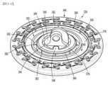
アンビルヘッド940は、リングアセンブリ950を受容するように寸法決定された凹部970を内部に画定する内側表面972を含む。内側表面972は、環状溝975を内部に画定する外周973を有する。溝975は、凹部970から半径方向に外向きに延在し、凹部970と連通している。溝975は、アンビルヘッド940の組織接触表面958に隣接して配設され、アンビルヘッド940の内側表面972の外周973の周囲で円周方向に延在する。溝975の高さは、その近位レッジ975aと遠位レッジ975bとの間に画定される。
リングアセンブリ940は、上記のバックアップ部材476と同様のバックアップ部材976と、カットリング978とを含む。バックアップ部材976は、アンビルヘッド940の凹部970内に受容され、カットリング978は、バックアップ部材976内に入れ子になっている。カットリングは、環状内側本体部分978aと、内側本体部分978aと一体的に形成され、かつその周囲で円周方向に配設された環状外側本体部分978bとを含む。内側本体部分および外側本体部分978a、978bは、ポリテトラフルオロエチレン、ポリプロピレン、またはポリエステルの単一片から形成されてもよい。他の材料も企図される。いくつかの実施形態では、外側本体部分978bは、内側本体部分978aに取り付けられた別個の部品であってもよい。
カットリング978の内側本体部分978aは、バックアップ部材976上で支持され、アンビルヘッド940の凹部970内に配設され、カットリング978の外側本体部分978bは、アンビルヘッド940の溝975の近位レッジ975aと遠位レッジ975bとの間に捕捉される。カットリング978は、アンビルヘッド940の凹部970の直径よりも大きい直径を有し、これによりカットリング978は、組み立て中に凹部970内に圧力嵌めされ得る。いったん組み立てられると、カットリング978の外側本体部分978bは、バックアップ部材976を越えて半径方向に延在する。カットリング978の外側本体部分978bが近位レッジおよび遠位レッジ975a、975bと重なり合うため、溝975の外へのカットリング978の外側本体部分978bの近位および遠位の両方の移動は、抵抗される。カットリング978の外側本体部分978bは、後述されるように、溝975内でカットリング978の外側本体部分978bのある程度の遊びを可能にするために、内側本体部分978aに対して低減された厚さを有してもよい。実施形態では、カットリング978の内側本体部分978aの高さは、溝975の高さと実質的に同様または同じであってもよい。 An
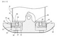
動作中、本実施形態の外科用アンビルアセンブリ926を有する円形ステープリング機器を発射する前に、バックアップ部材976とカットリング978とを含むリングアセンブリ950は、その格納位置または近位位置にある。脆弱保持具部材(明示的には示されていない)は、図53に示されるように、バックアップ部材976とアンビルヘッド940の内側表面972との間に挿入されて、近位位置でリングアセンブリ950を支持する。リングアセンブリ950が近位位置にあると、バックアップ部材976は、アンビル中心ロッドによって係合され、これによりアンビルヘッド940は、第1の動作状態で保持される。 In operation, prior to firing the circular stapling instrument with
ステープリング機器が作動すると、例えば図6に示される環状ナイフ30などの環状ナイフは、カットリング978と係合するように前進し、カットリング978の内側本体部分978aからカットリング978の外側本体部分978bを切り離すか、または剪断する。カットリング978を切り開くと、環状ナイフ30は、バックアップ部材976に係合し、それによってバックアップ部材976を遠位位置に向かって駆動する。 When the stapling instrument is actuated, an annular knife, such as, for example,
カットリング978の内側本体部分978aがバックアップ部材976と共に保持されているため、内側本体部分978aは、バックアップ部材976と共に遠位位置に向かって移動する。カットリング978の外側本体部分978bは、アンビルヘッド940の内側表面972の外周973と環状ナイフ30の外側表面との間に捕捉される。したがって、図54に示されるように、カットリング978の内側本体部分978aが遠位に前進すると、カットリング978の外側本体部分978bは、溝975内で保持される。 Because the
リングアセンブリ950が遠位位置に向かって前進すると、バックアップ部材976は、アンビル中心ロッドから係合解除し、アンビルヘッド940がアンビル中心ロッドに対して枢動することを可能にする。アンビルヘッド940は、本明細書に記載される任意の方法でアンビル中心ロッドに対して自動で枢動するように構成され得ることが企図される。実施形態では、アンビルヘッド940は、それが自動か手動かにかかわらず、任意の好適な枢動機構を介して枢動し得る。 As
図55を参照すると、環状ナイフ30をその開始位置に格納すると、環状ナイフ30の外側表面とカットリング978の外側本体部分978bの内周表面979との間の摩擦係合により、カットリング978の外側本体部分978bは、溝975内で近位に移動する。カットリング978の外側本体部分978bが近位レッジ975aに接触するまで、カットリング978の外側本体部分978bは、後退している環状ナイフ30によって近位方向に引っ張られる。カットリング978の外側本体部分978bが近位レッジ975aと接触すると、外側本体部分975bおよび内側本体部分978aは、互いから軸方向に離間し、カットリング978内に留まっているステープルが取り外され得る通路982を形成する。 55, when the
当業者は、本明細書で具体的に説明され、添付図面に例示されたデバイスおよび方法が非限定的な例示的実施形態であることを理解するであろう。ある例示的な実施形態に関連して例示または記載されている要素および特徴は、本開示の範囲から逸脱することなく、別の要素および特徴と組み合わせられ得ることが想定されている。同様に、当業者であれば、上記の実施形態に基づく本開示のさらなる特徴および利点を理解するであろう。したがって、本開示は、添付の特許請求の範囲によって示される場合を除いて、特に示されて記載されたものによって限定されるものではない。
Those skilled in the art will appreciate that the devices and methods specifically described herein and illustrated in the accompanying drawings are non-limiting exemplary embodiments. It is contemplated that the elements and features illustrated or described in connection with certain exemplary embodiments may be combined with other elements and features without departing from the scope of the present disclosure. Similarly, those skilled in the art will appreciate further features and advantages of the present disclosure based on the above-described embodiments. Accordingly, the present disclosure is not to be limited by what has been particularly shown and described, except as indicated by the appended claims.
Claims (6)
Translated fromJapaneseアンビル中心ロッドと、
前記アンビル中心ロッドに枢動可能に結合されているアンビルヘッドであって、前記アンビルヘッドは、第1の動作状態と第2の傾斜状態との間で移動可能であり、前記アンビルヘッドは、内側表面を含み、前記内側表面は、前記内側表面における凹部と、前記凹部から半径方向に外向きに延在する溝とを画定し、前記溝は、近位レッジと遠位レッジとを有する、アンビルヘッドと、
リングアセンブリであって、
前記アンビルヘッドの前記凹部内に配置されているバックアップ部材と、
前記バックアップ部材と入れ子になっているカットリングであって、前記アンビルヘッドの前記溝内に捕捉されているカットリングと
を含むリングアセンブリと
を備え、
前記リングアセンブリは、前記アンビルヘッドが前記第1の動作状態から枢動することを防止する近位位置から、前記アンビルヘッドが前記第2の傾斜状態に枢動することを可能にする遠位位置まで、前記凹部内で移動可能であり、
前記カットリングは、
前記アンビルヘッドの前記凹部内に配置されている環状の内側本体部分と、
前記アンビルヘッドの前記溝の前記近位レッジと前記遠位レッジとの間に捕捉されている環状の外側本体部分と
を含み、
前記外側本体部分は、環状ナイフが前記カットリングを通って前進することに応じて、前記内側本体部分から接続解除されるように構成されており、
前記カットリングの前記外側本体部分は、前記外側本体部分が前記近位レッジに接触するまで、前記環状ナイフが後退することに応じて近位方向に引っ張られるように構成されており、前記外側本体部分および前記内側本体部分は、通路を画定するように互いに軸方向に離間されていることを特徴とする、外科用アンビルアセンブリ。A surgical anvil assembly foruse with acircular stapling instrument,the surgical anvil assembly comprising:
an anvil center rod;
an anvil head pivotallycoupled to the anvil center rod, the anvil headbeing movable between a first operating state and a second tilted state, the anvil head an anvil comprising a surface, the inner surface defining a recess in the inner surface and agroove extending radially outwardly from the recess, the groove having a proximal ledge and a distal ledge; a head;
A ring assembly,
a backup memberdisposed within the recess of the anvil head;
a cut ring nested with the backup member, the cutringcaptured within the groove of the anvil head;
a ringassemblyincluding
with
The ring assemblycomprises a distal position that allows the anvil head to pivot to the second tilted state from a proximal position that prevents the anvil head from pivoting from thefirst operating state.is movable within the recess to a position;
The cut ring is
an annular inner body portion disposed within the recess of the anvil head;
an annular outer body portion captured between the proximal and distal ledges of the groove of the anvil head;
including
the outer body portion is configured to disconnect from the inner body portion in response to advancement of an annular knife through the cut ring;
the outer body portion of the cut ring is configured to be pulled proximally in response to retraction of the annular knife until the outer body portion contacts the proximal ledge; A surgical anvil assembly, wherein a portion and said inner body portion are axially spaced from each other to define a passageway.
Applications Claiming Priority (22)
| Application Number | Priority Date | Filing Date | Title |
|---|---|---|---|
| US201862649325P | 2018-03-28 | 2018-03-28 | |
| US201862649304P | 2018-03-28 | 2018-03-28 | |
| US201862649217P | 2018-03-28 | 2018-03-28 | |
| US201862649227P | 2018-03-28 | 2018-03-28 | |
| US201862649200P | 2018-03-28 | 2018-03-28 | |
| US201862649241P | 2018-03-28 | 2018-03-28 | |
| US201862649267P | 2018-03-28 | 2018-03-28 | |
| US201862649278P | 2018-03-28 | 2018-03-28 | |
| US201862649176P | 2018-03-28 | 2018-03-28 | |
| US201862649341P | 2018-03-28 | 2018-03-28 | |
| US62/649,304 | 2018-03-28 | ||
| US62/649,278 | 2018-03-28 | ||
| US62/649,176 | 2018-03-28 | ||
| US62/649,217 | 2018-03-28 | ||
| US62/649,200 | 2018-03-28 | ||
| US62/649,227 | 2018-03-28 | ||
| US62/649,325 | 2018-03-28 | ||
| US62/649,267 | 2018-03-28 | ||
| US62/649,341 | 2018-03-28 | ||
| US62/649,241 | 2018-03-28 | ||
| US16/275,656 | 2019-02-14 | ||
| US16/275,656US11000286B2 (en) | 2018-03-28 | 2019-02-14 | Surgical anvil assemblies for surgical stapling instruments |
Publications (2)
| Publication Number | Publication Date |
|---|---|
| JP2019171043A JP2019171043A (en) | 2019-10-10 |
| JP7300856B2true JP7300856B2 (en) | 2023-06-30 |
Family
ID=65995599
Family Applications (10)
| Application Number | Title | Priority Date | Filing Date |
|---|---|---|---|
| JP2019047917AActiveJP7300857B2 (en) | 2018-03-28 | 2019-03-15 | Surgical anvil assembly for surgical stapling instruments |
| JP2019047907AActiveJP7456726B2 (en) | 2018-03-28 | 2019-03-15 | Surgical anvil assembly for surgical stapling equipment |
| JP2019047905AActiveJP7245085B2 (en) | 2018-03-28 | 2019-03-15 | Surgical anvil assembly for surgical stapling instruments |
| JP2019047915AActiveJP7346046B2 (en) | 2018-03-28 | 2019-03-15 | Surgical anvil assembly for surgical stapling equipment |
| JP2019047912AActiveJP7300856B2 (en) | 2018-03-28 | 2019-03-15 | Surgical anvil assembly for surgical stapling instruments |
| JP2019047916AActiveJP7349804B2 (en) | 2018-03-28 | 2019-03-15 | Surgical anvil assembly for surgical stapling equipment |
| JP2019047914AActiveJP7349803B2 (en) | 2018-03-28 | 2019-03-15 | Surgical anvil assembly for surgical stapling equipment |
| JP2019047908AActiveJP7455513B2 (en) | 2018-03-28 | 2019-03-15 | Surgical anvil assembly for surgical stapling equipment |
| JP2019047906AActiveJP7468994B2 (en) | 2018-03-28 | 2019-03-15 | Surgical anvil assembly for a surgical stapling instrument |
| JP2019047909AActiveJP7245681B2 (en) | 2018-03-28 | 2019-03-15 | Surgical anvil assembly for surgical stapling instruments |
Family Applications Before (4)
| Application Number | Title | Priority Date | Filing Date |
|---|---|---|---|
| JP2019047917AActiveJP7300857B2 (en) | 2018-03-28 | 2019-03-15 | Surgical anvil assembly for surgical stapling instruments |
| JP2019047907AActiveJP7456726B2 (en) | 2018-03-28 | 2019-03-15 | Surgical anvil assembly for surgical stapling equipment |
| JP2019047905AActiveJP7245085B2 (en) | 2018-03-28 | 2019-03-15 | Surgical anvil assembly for surgical stapling instruments |
| JP2019047915AActiveJP7346046B2 (en) | 2018-03-28 | 2019-03-15 | Surgical anvil assembly for surgical stapling equipment |
Family Applications After (5)
| Application Number | Title | Priority Date | Filing Date |
|---|---|---|---|
| JP2019047916AActiveJP7349804B2 (en) | 2018-03-28 | 2019-03-15 | Surgical anvil assembly for surgical stapling equipment |
| JP2019047914AActiveJP7349803B2 (en) | 2018-03-28 | 2019-03-15 | Surgical anvil assembly for surgical stapling equipment |
| JP2019047908AActiveJP7455513B2 (en) | 2018-03-28 | 2019-03-15 | Surgical anvil assembly for surgical stapling equipment |
| JP2019047906AActiveJP7468994B2 (en) | 2018-03-28 | 2019-03-15 | Surgical anvil assembly for a surgical stapling instrument |
| JP2019047909AActiveJP7245681B2 (en) | 2018-03-28 | 2019-03-15 | Surgical anvil assembly for surgical stapling instruments |
Country Status (6)
| Country | Link |
|---|---|
| US (15) | US11006959B2 (en) |
| EP (10) | EP3556304B1 (en) |
| JP (10) | JP7300857B2 (en) |
| CN (10) | CN110313954A (en) |
| AU (10) | AU2019201193A1 (en) |
| ES (4) | ES2994041T3 (en) |
Families Citing this family (7)
| Publication number | Priority date | Publication date | Assignee | Title |
|---|---|---|---|---|
| WO2017096502A1 (en)* | 2015-12-07 | 2017-06-15 | Covidien Lp | Anvil assembly and delivery system |
| US10582754B2 (en) | 2017-03-08 | 2020-03-10 | Toly Management Ltd. | Cosmetic container |
| US11006959B2 (en) | 2018-03-28 | 2021-05-18 | Covidien Lp | Surgical anvil assemblies for surgical stapling instruments |
| US11291450B2 (en)* | 2018-12-31 | 2022-04-05 | Cilag Gmbh International | Anvil for circular surgical stapler and associated method of manufacture with MIM |
| EP3965664A1 (en)* | 2019-07-24 | 2022-03-16 | Boston Scientific Scimed, Inc. | Fastening device |
| JP7654397B2 (en)* | 2020-12-18 | 2025-04-01 | 株式会社シマノ | Spinning reels |
| CN114831701B (en)* | 2022-03-11 | 2023-03-24 | 广州德脉医疗器械有限公司 | Electrically-driven prepuce cutting anastomat |
Citations (1)
| Publication number | Priority date | Publication date | Assignee | Title |
|---|---|---|---|---|
| JP2015093189A (en) | 2013-11-13 | 2015-05-18 | コヴィディエン リミテッド パートナーシップ | Anvil assembly with frangible retaining member |
Family Cites Families (244)
| Publication number | Priority date | Publication date | Assignee | Title |
|---|---|---|---|---|
| CA908529A (en) | 1972-08-29 | V. Astafiev Georgy | Surgical instrument for suturing hollow organs in infants | |
| FR1461464A (en) | 1965-08-20 | 1966-02-25 | Niiex Khirurgicheskoi Apparatu | Surgical device for suturing organs |
| CH470170A (en) | 1968-02-02 | 1969-03-31 | Vnii Khirurgicheskoi Apparatur | Device for applying round anastomoses |
| US3638652A (en) | 1970-06-01 | 1972-02-01 | James L Kelley | Surgical instrument for intraluminal anastomosis |
| US4304236A (en) | 1977-05-26 | 1981-12-08 | United States Surgical Corporation | Stapling instrument having an anvil-carrying part of particular geometric shape |
| US4603693A (en) | 1977-05-26 | 1986-08-05 | United States Surgical Corporation | Instrument for circular surgical stapling of hollow body organs and disposable cartridge therefor |
| US4573468A (en) | 1977-05-26 | 1986-03-04 | United States Surgical Corporation | Hollow body organ stapling instrument and disposable cartridge employing relief vents |
| US4207898A (en) | 1978-03-27 | 1980-06-17 | Senco Products, Inc. | Intralumenal anastomosis surgical stapling instrument |
| US4198982A (en) | 1978-03-31 | 1980-04-22 | Memorial Hospital For Cancer And Allied Diseases | Surgical stapling instrument and method |
| PL121343B1 (en) | 1978-12-06 | 1982-04-30 | Zaklad Doswiadczalny Przy Zakladach Urzadzen Chemicznych "Metalchem" | Rolling mill for transversely ribbed pipes |
| SU1088712A1 (en) | 1979-11-14 | 1984-04-30 | Всесоюзный научно-исследовательский и испытательный институт медицинской техники | Apparatus for circular suture of blood vessels |
| US4319576A (en) | 1980-02-26 | 1982-03-16 | Senco Products, Inc. | Intralumenal anastomosis surgical stapling instrument |
| US4289133A (en) | 1980-02-28 | 1981-09-15 | Senco Products, Inc. | Cut-through backup washer for the scalpel of an intraluminal surgical stapling instrument |
| US4606343A (en) | 1980-08-18 | 1986-08-19 | United States Surgical Corporation | Self-powered surgical fastening instrument |
| US4351466A (en) | 1980-10-16 | 1982-09-28 | United States Surgical Corporation | Disposable instrument for surgical fastening |
| US4379457A (en) | 1981-02-17 | 1983-04-12 | United States Surgical Corporation | Indicator for surgical stapler |
| US4476863A (en) | 1981-03-09 | 1984-10-16 | Kanshin Nikolai N | Surgical instrument for establishing circular coloanastomoses |
| US4576167A (en) | 1981-09-03 | 1986-03-18 | United States Surgical Corporation | Surgical stapler apparatus with curved shaft |
| SU1114405A1 (en) | 1982-02-23 | 1984-09-23 | Всесоюзный научно-исследовательский и испытательный институт медицинской техники | Surgical suturing apparatus for placing compression anastomoses on the organs of digestive tract |
| US4485817A (en) | 1982-05-28 | 1984-12-04 | United States Surgical Corporation | Surgical stapler apparatus with flexible shaft |
| US4473077A (en) | 1982-05-28 | 1984-09-25 | United States Surgical Corporation | Surgical stapler apparatus with flexible shaft |
| US4488523A (en) | 1982-09-24 | 1984-12-18 | United States Surgical Corporation | Flexible, hydraulically actuated device for applying surgical fasteners |
| US4592354A (en) | 1983-10-11 | 1986-06-03 | Senmed, Inc. | Tissue retention spool for intraluminal anastomotic surgical stapling instrument and methods |
| US4505414A (en) | 1983-10-12 | 1985-03-19 | Filipi Charles J | Expandable anvil surgical stapler |
| US4550870A (en) | 1983-10-13 | 1985-11-05 | Alchemia Ltd. Partnership | Stapling device |
| IT1173284B (en) | 1984-02-16 | 1987-06-18 | Riccardo Rosati | CIRCULAR MECHANICAL STAPLING MACHINE |
| US4667673A (en) | 1984-03-12 | 1987-05-26 | American Cyanamid Company | Anastomotic device applicator and method |
| US4671445A (en) | 1984-08-09 | 1987-06-09 | Baxter Travenol Laboratories, Inc. | Flexible surgical stapler assembly |
| US4754909A (en) | 1984-08-09 | 1988-07-05 | Barker John M | Flexible stapler |
| US4559805A (en)* | 1984-09-28 | 1985-12-24 | Butler Manufacturing Company | Hand seamer |
| AU582625B2 (en) | 1985-01-28 | 1989-04-06 | Ethicon Inc. | Tissue gripper for use with intraluminal stapling device |
| US4703887A (en) | 1985-01-28 | 1987-11-03 | Ethicon, Inc. | Collapsible purse string aid for use with intraluminal stapling device |
| JPS635697Y2 (en) | 1985-04-04 | 1988-02-17 | ||
| US4700703A (en) | 1986-03-27 | 1987-10-20 | Semion Resnick | Cartridge assembly for a surgical stapling instrument |
| US4903697A (en) | 1986-03-27 | 1990-02-27 | Semion Resnick | Cartridge assembly for a surgical stapling instrument |
| US4817847A (en) | 1986-04-21 | 1989-04-04 | Finanzaktiengesellschaft Globe Control | Instrument and a procedure for performing an anastomosis |
| US4917114A (en) | 1986-10-17 | 1990-04-17 | United States Surgical Corporation | Surgical fastener and surgical stapling apparatus |
| US4873977A (en) | 1987-02-11 | 1989-10-17 | Odis L. Avant | Stapling method and apparatus for vesicle-urethral re-anastomosis following retropubic prostatectomy and other tubular anastomosis |
| US5119983A (en) | 1987-05-26 | 1992-06-09 | United States Surgical Corporation | Surgical stapler apparatus |
| AU636189B2 (en)* | 1987-05-26 | 1993-04-22 | United States Surgical Corporation | An anvil assembly for a surgical stapler apparatus |
| US5158222A (en) | 1987-05-26 | 1992-10-27 | United States Surgical Corp. | Surgical stapler apparatus |
| US5285944A (en) | 1987-05-26 | 1994-02-15 | United States Surgical Corporation | Surgical stapler apparatus |
| SU1616624A1 (en) | 1987-07-14 | 1990-12-30 | Предприятие П/Я А-3697 | Surgical suturing apparatus |
| US4907591A (en) | 1988-03-29 | 1990-03-13 | Pfizer Hospital Products Group, Inc. | Surgical instrument for establishing compression anastomosis |
| US5193731A (en) | 1988-07-01 | 1993-03-16 | United States Surgical Corporation | Anastomosis surgical stapling instrument |
| US5005749A (en) | 1988-07-01 | 1991-04-09 | United States Surgical Corp. | Anastomosis surgical stapling instrument |
| US5197648A (en) | 1988-11-29 | 1993-03-30 | Gingold Bruce S | Surgical stapling apparatus |
| AU4742190A (en) | 1988-11-29 | 1990-06-26 | Bruce S. Gingold | Surgical stapling apparatus |
| US4893662A (en) | 1988-12-06 | 1990-01-16 | Vito Gervasi | Cutting tool |
| CH677728A5 (en) | 1989-10-17 | 1991-06-28 | Bieffe Medital Sa | |
| US5366462A (en) | 1990-08-28 | 1994-11-22 | Robert L. Kaster | Method of side-to-end vascular anastomotic stapling |
| US5047039A (en) | 1990-09-14 | 1991-09-10 | Odis Lynn Avant | Method and apparatus for effecting dorsal vein ligation and tubular anastomosis and laparoscopic prostatectomy |
| US5253793A (en) | 1990-09-17 | 1993-10-19 | United States Surgical Corporation | Apparatus for applying two-part surgical fasteners |
| US5104025A (en) | 1990-09-28 | 1992-04-14 | Ethicon, Inc. | Intraluminal anastomotic surgical stapler with detached anvil |
| US5042707A (en) | 1990-10-16 | 1991-08-27 | Taheri Syde A | Intravascular stapler, and method of operating same |
| CA2055943C (en) | 1990-12-06 | 2003-09-23 | Daniel P. Rodak | Surgical fastening apparatus with locking mechanism |
| US5122156A (en) | 1990-12-14 | 1992-06-16 | United States Surgical Corporation | Apparatus for securement and attachment of body organs |
| US5222963A (en) | 1991-01-17 | 1993-06-29 | Ethicon, Inc. | Pull-through circular anastomosic intraluminal stapler with absorbable fastener means |
| ATE135182T1 (en) | 1991-03-29 | 1996-03-15 | Perouse Implant Lab | SURGICAL STAPLE SEWING DEVICE |
| US5221036A (en) | 1991-06-11 | 1993-06-22 | Haruo Takase | Surgical stapler |
| US5333773A (en) | 1991-08-23 | 1994-08-02 | Ethicon, Inc. | Sealing means for endoscopic surgical anastomosis stapling instrument |
| GR920100358A (en) | 1991-08-23 | 1993-06-07 | Ethicon Inc | Surgical anastomosis stapling instrument. |
| US5350104A (en) | 1991-08-23 | 1994-09-27 | Ethicon, Inc. | Sealing means for endoscopic surgical anastomosis stapling instrument |
| US5474223A (en) | 1991-10-18 | 1995-12-12 | United States Surgical Corporation | Surgical fastener applying apparatus |
| US5443198A (en) | 1991-10-18 | 1995-08-22 | United States Surgical Corporation | Surgical fastener applying apparatus |
| US5197649A (en) | 1991-10-29 | 1993-03-30 | The Trustees Of Columbia University In The City Of New York | Gastrointestinal endoscoptic stapler |
| US5433721A (en) | 1992-01-17 | 1995-07-18 | Ethicon, Inc. | Endoscopic instrument having a torsionally stiff drive shaft for applying fasteners to tissue |
| US5188638A (en) | 1992-02-06 | 1993-02-23 | Tzakis Andreas G | Apparatus and method for preforming anastomosis fastener securement of hollow organs |
| US5271543A (en) | 1992-02-07 | 1993-12-21 | Ethicon, Inc. | Surgical anastomosis stapling instrument with flexible support shaft and anvil adjusting mechanism |
| US5348259A (en) | 1992-02-10 | 1994-09-20 | Massachusetts Institute Of Technology | Flexible, articulable column |
| US5282810A (en) | 1992-04-08 | 1994-02-01 | American Cyanamid Company | Surgical anastomosis device |
| US5355897A (en) | 1992-04-16 | 1994-10-18 | Ethicon, Inc. | Method of performing a pyloroplasty/pylorectomy using a stapler having a shield |
| US5314435A (en) | 1992-05-19 | 1994-05-24 | United States Surgical Corporation | Anvil delivery system |
| US5344059A (en) | 1992-05-19 | 1994-09-06 | United States Surgical Corporation | Surgical apparatus and anvil delivery system therefor |
| US5658300A (en) | 1992-06-04 | 1997-08-19 | Olympus Optical Co., Ltd. | Tissue fixing surgical instrument, tissue-fixing device, and method of fixing tissues |
| JPH0647050A (en) | 1992-06-04 | 1994-02-22 | Olympus Optical Co Ltd | Tissue suture and ligature device |
| US5360154A (en) | 1992-07-17 | 1994-11-01 | United States Surgical Corporation | Apparatus for creating partial anastomoses |
| US5330486A (en) | 1992-07-29 | 1994-07-19 | Wilk Peter J | Laparoscopic or endoscopic anastomosis technique and associated instruments |
| US5261920A (en) | 1992-08-21 | 1993-11-16 | Ethicon, Inc. | Anvil bushing for circular stapler |
| US5368215A (en) | 1992-09-08 | 1994-11-29 | United States Surgical Corporation | Surgical apparatus and detachable anvil rod therefor |
| US5309927A (en) | 1992-10-22 | 1994-05-10 | Ethicon, Inc. | Circular stapler tissue retention spring method |
| US5314436A (en) | 1992-10-30 | 1994-05-24 | Wilk Peter J | Method and apparatus for performing end-to-end anastomoses |
| US5404870A (en) | 1993-05-28 | 1995-04-11 | Ethicon, Inc. | Method of using a transanal inserter |
| US5503320A (en) | 1993-08-19 | 1996-04-02 | United States Surgical Corporation | Surgical apparatus with indicator |
| US5437684A (en) | 1993-10-01 | 1995-08-01 | United States Surgical Corporation | Circular anastomosis device |
| US5454825A (en) | 1993-10-01 | 1995-10-03 | United States Surgical Corporation | Circular anastomosis device with seal |
| US5522534A (en) | 1993-10-01 | 1996-06-04 | United States Surgical Corporation | Anvil for surgical stapler |
| US5447514A (en) | 1993-10-01 | 1995-09-05 | United States Surgical Corporation | Circular anastomosis device |
| CA2132917C (en) | 1993-10-07 | 2004-12-14 | John Charles Robertson | Circular anastomosis device |
| US5860581A (en) | 1994-03-24 | 1999-01-19 | United States Surgical Corporation | Anvil for circular stapler |
| US5715987A (en) | 1994-04-05 | 1998-02-10 | Tracor Incorporated | Constant width, adjustable grip, staple apparatus and method |
| WO1995035065A1 (en) | 1994-06-17 | 1995-12-28 | Heartport, Inc. | Surgical stapling instrument and method thereof |
| US5881943A (en) | 1994-06-17 | 1999-03-16 | Heartport, Inc. | Surgical anastomosis apparatus and method thereof |
| US5732872A (en) | 1994-06-17 | 1998-03-31 | Heartport, Inc. | Surgical stapling instrument |
| CA2146508C (en) | 1994-08-25 | 2006-11-14 | Robert H. Schnut | Anvil for circular stapler |
| AU708637B2 (en) | 1994-08-25 | 1999-08-12 | United States Surgical Corporation | Anvil for circular stapler |
| US5685474A (en) | 1994-10-04 | 1997-11-11 | United States Surgical Corporation | Tactile indicator for surgical instrument |
| US5868760A (en) | 1994-12-07 | 1999-02-09 | Mcguckin, Jr.; James F. | Method and apparatus for endolumenally resectioning tissue |
| US5720755A (en) | 1995-01-18 | 1998-02-24 | Dakov; Pepi | Tubular suturing device and methods of use |
| US5904697A (en) | 1995-02-24 | 1999-05-18 | Heartport, Inc. | Devices and methods for performing a vascular anastomosis |
| DE19509115C2 (en) | 1995-03-16 | 1997-11-27 | Deutsche Forsch Luft Raumfahrt | Surgical device for preparing an anastomosis using minimally invasive surgical techniques |
| US5769841A (en) | 1995-06-13 | 1998-06-23 | Electroscope, Inc. | Electrosurgical apparatus for laparoscopic and like procedures |
| US5839639A (en) | 1995-08-17 | 1998-11-24 | Lasersurge, Inc. | Collapsible anvil assembly and applicator instrument |
| AU701033B2 (en) | 1995-10-31 | 1999-01-21 | Bernafon Ag | Method and anastomotic instrument for use when performing an end-to-side anastomosis |
| US5836503A (en) | 1996-04-22 | 1998-11-17 | United States Surgical Corporation | Insertion device for surgical apparatus |
| US6050472A (en) | 1996-04-26 | 2000-04-18 | Olympus Optical Co., Ltd. | Surgical anastomosis stapler |
| US6119913A (en) | 1996-06-14 | 2000-09-19 | Boston Scientific Corporation | Endoscopic stapler |
| US5855312A (en) | 1996-07-25 | 1999-01-05 | Toledano; Haviv | Flexible annular stapler for closed surgery of hollow organs |
| US6338737B1 (en) | 1997-07-17 | 2002-01-15 | Haviv Toledano | Flexible annular stapler for closed surgery of hollow organs |
| US5865361A (en) | 1997-09-23 | 1999-02-02 | United States Surgical Corporation | Surgical stapling apparatus |
| US6117148A (en) | 1997-10-17 | 2000-09-12 | Ravo; Biagio | Intraluminal anastomotic device |
| US5951576A (en) | 1998-03-02 | 1999-09-14 | Wakabayashi; Akio | End-to-side vascular anastomosing stapling device |
| US6279809B1 (en) | 1998-03-10 | 2001-08-28 | Enrico Nicolo | Circular stapler for side to end, side to side and end to side anastomosis |
| US6517566B1 (en) | 1998-05-11 | 2003-02-11 | Surgical Connections, Inc. | Devices and methods for treating e.g. urinary stress incontinence |
| AU751697B2 (en) | 1998-05-11 | 2002-08-22 | Surgical Connections, Inc. | Devices and methods for treating e.g. urinary stress incontinence |
| US6478210B2 (en) | 2000-10-25 | 2002-11-12 | Scimed Life Systems, Inc. | Method and device for full thickness resectioning of an organ |
| US6585144B2 (en) | 1998-06-19 | 2003-07-01 | Acimed Life Systems, Inc. | Integrated surgical staple retainer for a full thickness resectioning device |
| US6126058A (en) | 1998-06-19 | 2000-10-03 | Scimed Life Systems, Inc. | Method and device for full thickness resectioning of an organ |
| US6629630B2 (en) | 1998-06-19 | 2003-10-07 | Scimed Life Systems, Inc. | Non-circular resection device and endoscope |
| US6601749B2 (en) | 1998-06-19 | 2003-08-05 | Scimed Life Systems, Inc. | Multi fire full thickness resectioning device |
| DE19837258A1 (en) | 1998-08-17 | 2000-03-02 | Deutsch Zentr Luft & Raumfahrt | Device for operating a surgical instrument for anastomosis of hollow organs |
| DE19836950B4 (en) | 1998-08-17 | 2004-09-02 | Deutsches Zentrum für Luft- und Raumfahrt e.V. | Surgical instrument in the form of a suturing device |
| US6203553B1 (en) | 1999-09-08 | 2001-03-20 | United States Surgical | Stapling apparatus and method for heart valve replacement |
| US6083241A (en) | 1998-11-23 | 2000-07-04 | Ethicon Endo-Surgery, Inc. | Method of use of a circular stapler for hemorrhoidal procedure |
| US6102271A (en) | 1998-11-23 | 2000-08-15 | Ethicon Endo-Surgery, Inc. | Circular stapler for hemorrhoidal surgery |
| US6626921B2 (en) | 1999-04-16 | 2003-09-30 | Integrated Vascular Interventional Technologies, L.C. | Externally positioned anvil apparatus for cutting anastomosis |
| US6402008B1 (en) | 1999-04-19 | 2002-06-11 | Deborah A. Lucas | Surgical stapler assembly with interchangeable heads |
| US6068636A (en) | 1999-04-23 | 2000-05-30 | Chen; Te-Chuan | Intra-intestinal bypass gun |
| US6716233B1 (en) | 1999-06-02 | 2004-04-06 | Power Medical Interventions, Inc. | Electromechanical driver and remote surgical instrument attachment having computer assisted control capabilities |
| US8025199B2 (en) | 2004-02-23 | 2011-09-27 | Tyco Healthcare Group Lp | Surgical cutting and stapling device |
| US7032798B2 (en) | 1999-06-02 | 2006-04-25 | Power Medical Interventions, Inc. | Electro-mechanical surgical device |
| US6793652B1 (en) | 1999-06-02 | 2004-09-21 | Power Medical Interventions, Inc. | Electro-mechanical surgical device |
| US6264087B1 (en) | 1999-07-12 | 2001-07-24 | Powermed, Inc. | Expanding parallel jaw device for use with an electromechanical driver device |
| US6981941B2 (en) | 1999-06-02 | 2006-01-03 | Power Medical Interventions | Electro-mechanical surgical device |
| US6491201B1 (en) | 2000-02-22 | 2002-12-10 | Power Medical Interventions, Inc. | Fluid delivery mechanism for use with anastomosing, stapling, and resecting instruments |
| US6193129B1 (en) | 2000-01-24 | 2001-02-27 | Ethicon Endo-Surgery, Inc. | Cutting blade for a surgical anastomosis stapling instrument |
| US6533157B1 (en) | 2000-02-22 | 2003-03-18 | Power Medical Interventions, Inc. | Tissue stapling attachment for use with an electromechanical driver device |
| US6488197B1 (en) | 2000-02-22 | 2002-12-03 | Power Medical Interventions, Inc. | Fluid delivery device for use with anastomosing resecting and stapling instruments |
| DE60136862D1 (en) | 2000-03-06 | 2009-01-15 | Tyco Healthcare | DEVICE FOR IMPLEMENTING A BYPASS IN THE DIGESTING SYSTEM |
| IL139788A (en) | 2000-11-20 | 2006-10-05 | Minelu Zonnenschein | Stapler for endoscopes |
| US6592596B1 (en) | 2000-05-10 | 2003-07-15 | Scimed Life Systems, Inc. | Devices and related methods for securing a tissue fold |
| US8286845B2 (en) | 2000-11-27 | 2012-10-16 | Boston Scientific Scimed, Inc. | Full thickness resection device control handle |
| US6398795B1 (en) | 2000-11-30 | 2002-06-04 | Scimed Life Systems, Inc. | Stapling and cutting in resectioning for full thickness resection devices |
| US6503259B2 (en) | 2000-12-27 | 2003-01-07 | Ethicon, Inc. | Expandable anastomotic device |
| US6632237B2 (en) | 2001-01-11 | 2003-10-14 | Bio-Seal Tech, Inc. | Device and method for sealing a puncture in a blood vessel |
| US6835199B2 (en) | 2001-01-31 | 2004-12-28 | Rex Medical, L.P. | Apparatus and method for resectioning gastro-esophageal tissue |
| US6769590B2 (en) | 2001-04-02 | 2004-08-03 | Susan E. Vresh | Luminal anastomotic device and method |
| EP2397080B1 (en)* | 2001-04-03 | 2018-08-01 | Covidien LP | Surgical stapling device |
| US6623227B2 (en) | 2001-07-27 | 2003-09-23 | Copemaster, Llc | Drill screw for adjusting molding relative to an underlying wall |
| US6632227B2 (en) | 2001-08-24 | 2003-10-14 | Scimed Life Systems, Inc. | Endoscopic resection devices |
| JP2005502421A (en) | 2001-09-17 | 2005-01-27 | ガルシア・ビセンテ ヒレテ | Craniotomy bone anchor |
| US6578751B2 (en) | 2001-09-26 | 2003-06-17 | Scimed Life Systems, Inc. | Method of sequentially firing staples using springs and a rotary or linear shutter |
| US20070060952A1 (en) | 2005-09-02 | 2007-03-15 | Roby Mark S | Surgical stapling device with coated knife blade |
| US6605098B2 (en) | 2001-09-28 | 2003-08-12 | Ethicon, Inc. | Surgical device for creating an anastomosis between first and second hollow organs |
| CA2462536C (en)* | 2001-10-05 | 2010-03-30 | Tyco Healthcare Group Lp | Tilt top anvil for a surgical fastener device |
| US6605078B2 (en) | 2001-11-26 | 2003-08-12 | Scimed Life Systems, Inc. | Full thickness resection device |
| DE10158246C1 (en) | 2001-11-28 | 2003-08-21 | Ethicon Endo Surgery Europe | Surgical stapling instrument |
| US20030111507A1 (en) | 2001-12-14 | 2003-06-19 | George Nunez | Balloon actuator for use in a resectioning device |
| US6981979B2 (en) | 2001-12-14 | 2006-01-03 | Enrico Nicolo | Surgical anastomotic devices |
| US6905504B1 (en) | 2002-02-26 | 2005-06-14 | Cardica, Inc. | Tool for performing end-to-end anastomosis |
| US7128748B2 (en) | 2002-03-26 | 2006-10-31 | Synovis Life Technologies, Inc. | Circular stapler buttress combination |
| US7141055B2 (en) | 2002-04-24 | 2006-11-28 | Surgical Connections, Inc. | Resection and anastomosis devices and methods |
| US6685079B2 (en) | 2002-05-24 | 2004-02-03 | Scimed Life Systems, Inc. | Full thickness resectioning device |
| US7195142B2 (en) | 2003-05-30 | 2007-03-27 | Tyco Healthcare Group Lp | End-to-end anastomosis instrument and method for performing same |
| US6769594B2 (en) | 2002-05-31 | 2004-08-03 | Tyco Healthcare Group, Lp | End-to-end anastomosis instrument and method for performing same |
| IL150855A (en) | 2002-07-22 | 2007-06-03 | Leonid Monassevitch | Intratubular anastomosis apparatus |
| CA2500785C (en) | 2002-10-04 | 2011-04-26 | Philip C. Roy | Pneumatic powered surgical stapling device |
| JP4422027B2 (en) | 2002-10-04 | 2010-02-24 | タイコ ヘルスケア グループ エルピー | Surgical stapling device |
| US7220237B2 (en) | 2002-10-23 | 2007-05-22 | Satiety, Inc. | Method and device for use in endoscopic organ procedures |
| EP1572012B1 (en) | 2002-12-20 | 2008-08-20 | Tyco Healthcare Group Lp | Vacuum assisted surgical stapler |
| KR100547166B1 (en) | 2003-04-11 | 2006-01-26 | 허윤석 | Improved Short-Stage Anastomator |
| EP1635712B1 (en) | 2003-06-20 | 2015-09-30 | Covidien LP | Surgical stapling device |
| CA2531909C (en) | 2003-07-16 | 2011-02-15 | Tyco Healthcare Group Lp | Surgical stapling device with tissue tensioner |
| US7686201B2 (en) | 2003-09-01 | 2010-03-30 | Tyco Healthcare Group Lp | Circular stapler for hemorrhoid operations |
| EP1680028B1 (en) | 2003-10-17 | 2012-01-25 | Tyco Healthcare Group LP | Surgical stapling device |
| US9055943B2 (en) | 2007-09-21 | 2015-06-16 | Covidien Lp | Hand held surgical handle assembly, surgical adapters for use between surgical handle assembly and surgical end effectors, and methods of use |
| US8806973B2 (en) | 2009-12-02 | 2014-08-19 | Covidien Lp | Adapters for use between surgical handle assembly and surgical end effector |
| US7585306B2 (en) | 2003-12-24 | 2009-09-08 | Maquet Cardiovascular Llc | Anastomosis device, tools and methods of using |
| US8590764B2 (en) | 2003-12-24 | 2013-11-26 | Boston Scientific Scimed, Inc. | Circumferential full thickness resectioning device |
| US7118528B1 (en) | 2004-03-16 | 2006-10-10 | Gregory Piskun | Hemorrhoids treatment method and associated instrument assembly including anoscope and cofunctioning tissue occlusion device |
| ES2400050T3 (en)* | 2004-03-19 | 2013-04-05 | Covidien Lp | Anvil set with improved cutting ring |
| EP1949861B1 (en) | 2004-03-19 | 2012-07-18 | Tyco Healthcare Group LP | Surgical stapling device |
| WO2005115254A2 (en) | 2004-05-17 | 2005-12-08 | Datascope Investment Corp. | Surgical stapling system |
| JP4257270B2 (en) | 2004-07-14 | 2009-04-22 | オリンパス株式会社 | Biological tissue suturing method and biological tissue suturing device |
| US7410086B2 (en) | 2004-07-28 | 2008-08-12 | Ethicon Endo-Surgery, Inc. | Electroactive polymer-based actuation mechanism for circular stapler |
| US7182239B1 (en) | 2004-08-27 | 2007-02-27 | Myers Stephan R | Segmented introducer device for a circular surgical stapler |
| US7922743B2 (en) | 2004-10-18 | 2011-04-12 | Tyco Healthcare Group Lp | Structure for applying sprayable wound treatment material |
| US7717313B2 (en) | 2004-10-18 | 2010-05-18 | Tyco Healthcare Group Lp | Surgical apparatus and structure for applying sprayable wound treatment material |
| US7938307B2 (en) | 2004-10-18 | 2011-05-10 | Tyco Healthcare Group Lp | Support structures and methods of using the same |
| US7455682B2 (en) | 2004-10-18 | 2008-11-25 | Tyco Healthcare Group Lp | Structure containing wound treatment material |
| CA2583590C (en) | 2004-10-18 | 2013-05-07 | Tyco Healthcare Group, Lp | Compression anastomosis device and method |
| US20060201989A1 (en) | 2005-03-11 | 2006-09-14 | Ojeda Herminio F | Surgical anvil and system for deploying the same |
| CN100435744C (en)* | 2005-08-04 | 2008-11-26 | 苏州天臣国际医疗科技有限公司 | Turnover nail-anvil assembly |
| US20070029363A1 (en) | 2005-08-07 | 2007-02-08 | Sergey Popov | Surgical apparatus with remote drive |
| US7407075B2 (en) | 2005-08-15 | 2008-08-05 | Tyco Healthcare Group Lp | Staple cartridge having multiple staple sizes for a surgical stapling instrument |
| US7401721B2 (en) | 2005-08-15 | 2008-07-22 | Tyco Healthcare Group Lp | Surgical stapling instruments including a cartridge having multiple staple sizes |
| US8540132B2 (en)* | 2006-05-16 | 2013-09-24 | Covidien Lp | Tilt anvil assembly |
| US20090082785A1 (en)* | 2007-09-24 | 2009-03-26 | Milliman Keith L | Anvil Delivery Device Accessory |
| US8011554B2 (en)* | 2008-01-09 | 2011-09-06 | Tyco Healthcare Group, Lp | Raised boss for staple guide |
| CN201216624Y (en)* | 2008-05-12 | 2009-04-08 | 商建忠 | Anastomat for circumcision |
| US8109426B2 (en)* | 2008-08-12 | 2012-02-07 | Tyco Healthcare Group Lp | Surgical tilt anvil assembly |
| US8181838B2 (en)* | 2008-09-10 | 2012-05-22 | Tyco Healthcare Group Lp | Surgical stapling device |
| US7837080B2 (en)* | 2008-09-18 | 2010-11-23 | Ethicon Endo-Surgery, Inc. | Surgical stapling instrument with device for indicating when the instrument has cut through tissue |
| US8231042B2 (en) | 2008-11-06 | 2012-07-31 | Tyco Healthcare Group Lp | Surgical stapler |
| US8453913B2 (en)* | 2009-02-06 | 2013-06-04 | Covidien Lp | Anvil for surgical stapler |
| US8418909B2 (en)* | 2009-06-02 | 2013-04-16 | Covidien Lp | Surgical instrument and method for performing a resection |
| DE102009059196A1 (en)* | 2009-12-17 | 2011-06-22 | Aesculap AG, 78532 | Surgical system for connecting body tissue |
| CN102188271B (en)* | 2010-03-08 | 2012-10-10 | 北京中法派尔特医疗设备有限公司 | Nail anvil assembly capable of falling sideways and resetting, and stapler using the anvil assembly |
| US8973640B1 (en)* | 2010-12-07 | 2015-03-10 | Hunter Engineering Company | Demount tool assembly and methods for automated tire changer machine |
| US9211122B2 (en)* | 2011-03-14 | 2015-12-15 | Ethicon Endo-Surgery, Inc. | Surgical access devices with anvil introduction and specimen retrieval structures |
| US8789737B2 (en) | 2011-04-27 | 2014-07-29 | Covidien Lp | Circular stapler and staple line reinforcement material |
| US8708212B2 (en) | 2011-10-18 | 2014-04-29 | Covidien Lp | Tilt top anvil with torsion spring |
| US9016547B2 (en)* | 2011-10-26 | 2015-04-28 | Covidien Lp | EEA tilt top anvil with ratchet/locking mechanism |
| US9220505B2 (en)* | 2011-12-16 | 2015-12-29 | Ethicon Endo-Surgery, Inc. | Surgical stapling instrument with locking feature to lock anvil actuator |
| US9186148B2 (en)* | 2012-01-05 | 2015-11-17 | Ethicon Endo-Surgery, Inc. | Tissue stapler anvil feature to prevent premature jaw opening |
| US20130284792A1 (en)* | 2012-04-26 | 2013-10-31 | Covidien Lp | Surgical Stapling Device Including A Camera |
| DE102012110312A1 (en)* | 2012-10-29 | 2014-04-30 | Aesculap Ag | Anastomosis instrument with swiveling anvil |
| US9463022B2 (en)* | 2012-12-17 | 2016-10-11 | Ethicon Endo-Surgery, Llc | Motor driven rotary input circular stapler with lockable flexible shaft |
| US9204881B2 (en)* | 2013-01-11 | 2015-12-08 | Covidien Lp | Buttress retainer for EEA anvil |
| US9782173B2 (en)* | 2013-03-07 | 2017-10-10 | Covidien Lp | Circular stapling device including buttress release mechanism |
| CN104042289A (en) | 2013-03-15 | 2014-09-17 | 柯惠Lp公司 | Operation fastener applying device |
| US9532780B2 (en)* | 2013-06-12 | 2017-01-03 | Covidien Lp | EEA anvil snap ring activator |
| US9668740B2 (en)* | 2013-06-14 | 2017-06-06 | Covidien Lp | Anvil assembly with sliding sleeve |
| US9629633B2 (en) | 2013-07-09 | 2017-04-25 | Covidien Lp | Surgical device, surgical adapters for use between surgical handle assembly and surgical loading units, and methods of use |
| US9750503B2 (en)* | 2013-07-11 | 2017-09-05 | Covidien Lp | Methods and devices for performing a surgical anastomosis |
| US9693773B2 (en) | 2013-09-11 | 2017-07-04 | Covidien Lp | Anvil assembly with sliding sleeve |
| US10709452B2 (en)* | 2013-09-23 | 2020-07-14 | Ethicon Llc | Methods and systems for performing circular stapling |
| WO2015065484A1 (en) | 2013-11-04 | 2015-05-07 | Covidien Lp | Surgical fastener applying apparatus |
| US9517070B2 (en)* | 2013-11-13 | 2016-12-13 | Covidien Lp | Anvil assembly and delivery system |
| US9655626B2 (en)* | 2014-04-28 | 2017-05-23 | Covidien Lp | Anvil assembly delivery system |
| US9867619B2 (en) | 2014-06-24 | 2018-01-16 | Covidien Lp | System for delivering an anvil assembly to a surgical site |
| US9861367B2 (en)* | 2014-06-24 | 2018-01-09 | Covidien Lp | Anvil assembly delivery systems |
| US9757133B2 (en) | 2014-07-09 | 2017-09-12 | Covidien Lp | Methods and devices for performing a surgical anastomosis |
| US9855045B2 (en) | 2014-12-09 | 2018-01-02 | Covidien Lp | Anvil assembly delivery system |
| US10426480B2 (en) | 2015-04-29 | 2019-10-01 | Covidien Lp | Cutting ring assembly with rigid cutting member |
| US10111668B2 (en) | 2015-07-02 | 2018-10-30 | Covidien Lp | Anvil assembly with snap backup ring |
| US10085756B2 (en)* | 2015-07-24 | 2018-10-02 | Covidien Lp | Anvil assembly and anvil assembly delivery system |
| WO2017096502A1 (en) | 2015-12-07 | 2017-06-15 | Covidien Lp | Anvil assembly and delivery system |
| CN105640605A (en)* | 2015-12-30 | 2016-06-08 | 北京派尔特医疗科技股份有限公司 | Inclinable nail abutting seat and tube-type anastomat |
| US20170360443A1 (en)* | 2016-06-21 | 2017-12-21 | Covidien Lp | Damage resistant anvil assembly |
| US11241232B2 (en)* | 2017-01-24 | 2022-02-08 | Covidien Lp | Surgical stapling device with resettable anvil assembly |
| US11090054B2 (en)* | 2017-08-07 | 2021-08-17 | Covidien Lp | Stapling device with resettable tilt anvil assembly |
| US10828026B2 (en) | 2017-08-08 | 2020-11-10 | Covidien Lp | Tiltable anvil assembly |
| US11006959B2 (en) | 2018-03-28 | 2021-05-18 | Covidien Lp | Surgical anvil assemblies for surgical stapling instruments |
- 2019
- 2019-02-14USUS16/275,541patent/US11006959B2/enactiveActive
- 2019-02-14USUS16/275,622patent/US11051820B2/enactiveActive
- 2019-02-14USUS16/275,570patent/US11246598B2/enactiveActive
- 2019-02-14USUS16/275,803patent/US11026689B2/enactiveActive
- 2019-02-14USUS16/275,514patent/US10881411B2/ennot_activeExpired - Fee Related
- 2019-02-14USUS16/275,749patent/US10959733B2/enactiveActive
- 2019-02-14USUS16/275,711patent/US11006961B2/ennot_activeExpired - Fee Related
- 2019-02-14USUS16/275,656patent/US11000286B2/ennot_activeExpired - Fee Related
- 2019-02-14USUS16/275,603patent/US11006960B2/enactiveActive
- 2019-02-14USUS16/275,850patent/US11033273B2/enactiveActive
- 2019-02-20AUAU2019201193Apatent/AU2019201193A1/ennot_activeAbandoned
- 2019-02-20AUAU2019201189Apatent/AU2019201189A1/ennot_activeAbandoned
- 2019-02-21AUAU2019201216Apatent/AU2019201216A1/ennot_activeAbandoned
- 2019-02-26AUAU2019201330Apatent/AU2019201330A1/ennot_activeAbandoned
- 2019-02-26AUAU2019201348Apatent/AU2019201348A1/ennot_activeAbandoned
- 2019-02-26AUAU2019201343Apatent/AU2019201343A1/ennot_activeAbandoned
- 2019-02-26AUAU2019201341Apatent/AU2019201341A1/ennot_activeAbandoned
- 2019-02-26AUAU2019201331Apatent/AU2019201331A1/ennot_activeAbandoned
- 2019-02-26AUAU2019201338Apatent/AU2019201338A1/ennot_activeAbandoned
- 2019-02-26AUAU2019201339Apatent/AU2019201339A1/ennot_activeAbandoned
- 2019-03-14CNCN201910194148.6Apatent/CN110313954A/enactivePending
- 2019-03-14CNCN201910194871.4Apatent/CN110313955B/enactiveActive
- 2019-03-15JPJP2019047917Apatent/JP7300857B2/enactiveActive
- 2019-03-15JPJP2019047907Apatent/JP7456726B2/enactiveActive
- 2019-03-15JPJP2019047905Apatent/JP7245085B2/enactiveActive
- 2019-03-15JPJP2019047915Apatent/JP7346046B2/enactiveActive
- 2019-03-15JPJP2019047912Apatent/JP7300856B2/enactiveActive
- 2019-03-15JPJP2019047916Apatent/JP7349804B2/enactiveActive
- 2019-03-15JPJP2019047914Apatent/JP7349803B2/enactiveActive
- 2019-03-15JPJP2019047908Apatent/JP7455513B2/enactiveActive
- 2019-03-15JPJP2019047906Apatent/JP7468994B2/enactiveActive
- 2019-03-15JPJP2019047909Apatent/JP7245681B2/enactiveActive
- 2019-03-25CNCN201910227236.1Apatent/CN110313957B/enactiveActive
- 2019-03-25CNCN201910228138.XApatent/CN110313963B/enactiveActive
- 2019-03-25CNCN201910227216.4Apatent/CN110313956B/enactiveActive
- 2019-03-25CNCN201910227336.4Apatent/CN110313958B/enactiveActive
- 2019-03-25CNCN201910227581.5Apatent/CN110313959B/enactiveActive
- 2019-03-25CNCN201910227585.3Apatent/CN110313960B/enactiveActive
- 2019-03-25CNCN201910227607.6Apatent/CN110313961B/enactiveActive
- 2019-03-25CNCN201910227610.8Apatent/CN110313962B/enactiveActive
- 2019-03-27EPEP19165622.2Apatent/EP3556304B1/enactiveActive
- 2019-03-27EPEP19165599.2Apatent/EP3545876B1/enactiveActive
- 2019-03-27EPEP19165627.1Apatent/EP3545877B1/enactiveActive
- 2019-03-27EPEP19165467.2Apatent/EP3545870B1/enactiveActive
- 2019-03-27EPEP19165571.1Apatent/EP3545875B1/enactiveActive
- 2019-03-27ESES19165599Tpatent/ES2994041T3/enactiveActive
- 2019-03-27EPEP19165482.1Apatent/EP3549535B1/enactiveActive
- 2019-03-27ESES19165571Tpatent/ES2882597T3/enactiveActive
- 2019-03-27ESES19165491Tpatent/ES2887652T3/enactiveActive
- 2019-03-27EPEP19165494.6Apatent/EP3545873B1/enactiveActive
- 2019-03-27ESES19165493Tpatent/ES2883696T3/enactiveActive
- 2019-03-27EPEP19165493.8Apatent/EP3545872B1/enactiveActive
- 2019-03-27EPEP19165491.2Apatent/EP3545871B1/enactiveActive
- 2019-03-27EPEP19165495.3Apatent/EP3545874B1/enactiveActive
- 2020
- 2020-12-21USUS17/128,650patent/US11653924B2/enactiveActive
- 2021
- 2021-05-10USUS17/315,723patent/US11730483B2/enactiveActive
- 2021-05-17USUS17/321,650patent/US11751878B2/enactiveActive
- 2021-06-29USUS17/362,155patent/US11832821B2/enactiveActive
- 2022
- 2022-02-08USUS17/666,826patent/US12023033B2/enactiveActive
Patent Citations (1)
| Publication number | Priority date | Publication date | Assignee | Title |
|---|---|---|---|---|
| JP2015093189A (en) | 2013-11-13 | 2015-05-18 | コヴィディエン リミテッド パートナーシップ | Anvil assembly with frangible retaining member |
Also Published As
Similar Documents
| Publication | Publication Date | Title |
|---|---|---|
| JP7300856B2 (en) | Surgical anvil assembly for surgical stapling instruments |
Legal Events
| Date | Code | Title | Description |
|---|---|---|---|
| A621 | Written request for application examination | Free format text:JAPANESE INTERMEDIATE CODE: A621 Effective date:20220314 | |
| A131 | Notification of reasons for refusal | Free format text:JAPANESE INTERMEDIATE CODE: A131 Effective date:20230210 | |
| A977 | Report on retrieval | Free format text:JAPANESE INTERMEDIATE CODE: A971007 Effective date:20230215 | |
| A521 | Request for written amendment filed | Free format text:JAPANESE INTERMEDIATE CODE: A523 Effective date:20230509 | |
| TRDD | Decision of grant or rejection written | ||
| A01 | Written decision to grant a patent or to grant a registration (utility model) | Free format text:JAPANESE INTERMEDIATE CODE: A01 Effective date:20230601 | |
| A61 | First payment of annual fees (during grant procedure) | Free format text:JAPANESE INTERMEDIATE CODE: A61 Effective date:20230620 | |
| R150 | Certificate of patent or registration of utility model | Ref document number:7300856 Country of ref document:JP Free format text:JAPANESE INTERMEDIATE CODE: R150 |