JP7300854B2 - ROBOT CONTROL DEVICE AND ROBOT CONTROL METHOD - Google Patents
ROBOT CONTROL DEVICE AND ROBOT CONTROL METHODDownload PDFInfo
- Publication number
- JP7300854B2 JP7300854B2JP2019043626AJP2019043626AJP7300854B2JP 7300854 B2JP7300854 B2JP 7300854B2JP 2019043626 AJP2019043626 AJP 2019043626AJP 2019043626 AJP2019043626 AJP 2019043626AJP 7300854 B2JP7300854 B2JP 7300854B2
- Authority
- JP
- Japan
- Prior art keywords
- command value
- torque
- control unit
- joint
- control
- Prior art date
- Legal status (The legal status is an assumption and is not a legal conclusion. Google has not performed a legal analysis and makes no representation as to the accuracy of the status listed.)
- Active
Links
Images


Classifications
- B—PERFORMING OPERATIONS; TRANSPORTING
- B25—HAND TOOLS; PORTABLE POWER-DRIVEN TOOLS; MANIPULATORS
- B25J—MANIPULATORS; CHAMBERS PROVIDED WITH MANIPULATION DEVICES
- B25J13/00—Controls for manipulators
- B25J13/08—Controls for manipulators by means of sensing devices, e.g. viewing or touching devices
- B—PERFORMING OPERATIONS; TRANSPORTING
- B25—HAND TOOLS; PORTABLE POWER-DRIVEN TOOLS; MANIPULATORS
- B25J—MANIPULATORS; CHAMBERS PROVIDED WITH MANIPULATION DEVICES
- B25J9/00—Programme-controlled manipulators
- B25J9/10—Programme-controlled manipulators characterised by positioning means for manipulator elements
Landscapes
- Engineering & Computer Science (AREA)
- Robotics (AREA)
- Mechanical Engineering (AREA)
- Human Computer Interaction (AREA)
- Manipulator (AREA)
Description
Translated fromJapaneseこの発明は、ロボットの位置姿勢と力を同時に制御可能なロボット制御装置及びロボット制御方法に関する。 The present invention relates to a robot control device and a robot control method capable of simultaneously controlling the position/orientation and force of a robot.
垂直多関節ロボット等のロボット(ロボットアーム)では、位置姿勢と力を同時(並列)に制御対象とするロボット制御装置が用いられている(例えば特許文献1参照)。なお、位置姿勢は、ロボットの位置及び姿勢のうちの少なくとも一方を表す。図9~図11に、ロボット制御装置1bの一例を示す。 A robot (robot arm) such as a vertical multi-joint robot uses a robot control device that simultaneously (parallelly) controls a position/orientation and a force (see, for example, Patent Document 1). Note that the position and orientation represent at least one of the position and orientation of the robot. 9 to 11 show an example of the
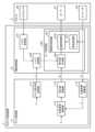
図9に示すロボット制御装置1bは、メイン制御部(上位コントローラ)11b、及び複数の関節制御部(下位コントローラ)12bを備えている。関節制御部12bは、ロボット2が有する関節毎に設けられている。なお、メイン制御部11bと各関節制御部12bとの間は通信線により接続されている。 A
また、図9に示すように、ロボット2は、関節毎に、モータ21及びセンサ22(トルクセンサ23及びエンコーダ24)を有している。モータ21及びセンサ22はそれぞれ、対応する関節制御部12bに対して電力線等により接続されている。トルクセンサ23は、対応する関節でのトルクの現在値を検出する。エンコーダ24は、対応する関節の角度の現在値を検出する。なお図10では、モータ21、トルクセンサ23及びエンコーダ24を一組のみ示している。 Further, as shown in FIG. 9, the
メイン制御部11bは、各関節制御部12bに指令値を出力することで、ロボット2全体を制御する。具体的には、メイン制御部11bは、力の指令値及び位置姿勢の指令値並びにロボット2が有する関節毎のトルクの現在値及び角度の現在値に基づいて、当該関節毎の速度の指令値を演算する。メイン制御部11bは、図10及び図11に示すように、力演算部111b、力制御部112b、位置姿勢演算部113b、位置姿勢制御部114b、指令値合成部115b及び指令値変換部116bを備えている。 The
力演算部111bは、ロボット2が有する関節毎のトルクの現在値に基づいて、ロボット2の力の現在値を演算する。ロボット2が有する関節毎のトルクは関節座標系で表されており、力演算部111bは、関節毎のトルクを直交座標系で表された力に変換する。図11において、τはトルクの現在値を表し、Fは力の現在値を表している。 The
力制御部112bは、力の指令値及び力演算部111bにより演算された力の現在値に基づいて、力制御の指令値を演算する。この力制御部112bでは、偏差演算器1121bで力の指令値と力の現在値との間の偏差を求め、係数乗算部1122bで偏差演算器1121bによる演算結果の偏差に対してゲインを乗算することで、力制御の指令値を得る。図11において、Frは力の指令値を表し、GFはゲインを表している。The
位置姿勢演算部113bは、ロボット2が有する関節毎の角度の現在値に基づいて、ロボット2の位置姿勢の現在値を演算する。ロボット2が有する関節毎の角度の現在値は関節座標系で表されており、位置姿勢演算部113bは、関節毎の角度の現在値を直交座標系で表された位置姿勢の現在値に変換する。図11において、θは角度の現在値を表し、Xは位置姿勢の現在値を表している。 The position/
位置姿勢制御部114bは、位置姿勢の指令値及び位置姿勢演算部113bにより演算された位置姿勢の現在値に基づいて、位置姿勢制御の指令値を演算する。この位置姿勢制御部114bでは、偏差演算器1141bで位置姿勢の指令値と位置姿勢の現在値との間の偏差を求め、係数乗算部1142bで偏差演算器1141bによる演算結果に対してゲインを乗算することで、位置姿勢制御の指令値を得る。図11において、Xrは位置姿勢の指令値を表し、GZはゲインを表している。The position/
指令値合成部115bは、力制御部112bにより演算された力制御の指令値及び位置姿勢制御部114bにより演算された位置姿勢制御の指令値を合成する。この指令値合成部115bでは、加算器1151bで力制御の指令値と位置姿勢制御の指令値とを加算する。 The command
指令値変換部116bは、指令値合成部115bによる合成結果を、ロボット2が有する関節毎の角速度の指令値に変換する。この指令値変換部116bでは、係数乗算部1161bで上記合成結果に対してヤコビ行列の逆行列を乗算する。すなわち、指令値変換部116bは、直交座標系で表された指令値を関節座標系で表された指令値に変換する。図11において、Jはヤコビ行列を表し、θ(ドット)rは角速度の指令値を表している。 The command
関節制御部12bは、メイン制御部11bからの指令に応じ、対応する関節に設けられたモータ21を制御する。関節制御部12bは、図10に示すように、トルク取得部121b及び関節角制御部122bを備えている。 The
トルク取得部121bは、対応する関節でのトルクの現在値を取得する。このトルク取得部121bにより取得されたトルクの現在値を示すデータは、メイン制御部11b(力演算部111b)に出力される。 The
関節角制御部122bは、メイン制御部11bにより演算された角速度の指令値及びロボット2が有する関節毎の角度の現在値に基づいて、対応する関節に設けられたモータ21に対する指令値を演算する。この関節角制御部122bでは、速度変換部1221bで角度の現在値を角速度の現在値に変換し、減算器1223bで角速度の指令値から速度変換部1221bで得られた角速度の現在値を減算し、PI制御部1224bで減算器1223bによる減算結果に基づいてPI制御を行うことで、モータ21に対する指令値を得る。 The joint
このように、図9~図11に示すロボット制御装置1bでは、複数の関節を連携して操作する必要があり、メイン制御部11bで、多関節の自由度(例えば6自由度)に対して位置姿勢と力を同時に制御演算した結果を合成し、当該合成結果を各軸の関節制御部12bへの信号に変換してから出力する。すなわち、このロボット制御装置1bでは、メイン制御部11bでコンプライアンス制御の主要な演算を実行する。そのため、このロボット制御装置1bでは、調整すべきパラメータを合理的に統合できる等のメリットがある。 As described above, in the
一般に、産業用ロボット等のロボットでは、力制御によって実現が求められる対象として精密な研磨の倣い動作等があり、整定動作又は追従動作のようなダイナミクスの性能向上が常に求められている。
一方、従来のロボット制御装置では、メイン制御部でフィードバック系を構成している。すなわち、このロボット制御装置では、ロボットから物理的にも通信的にも距離のある構成要素でフィードバック制御演算を行うことになる。よって、トルクセンサによるトルクの検出からモータへの指令値の入力までの遅延が長くなる。その結果、このロボット制御装置では、不可避的にむだ時間が入り込む余地が多くなり、安定性を維持できるハイゲイン化を抑制する要因になる。また、むだ時間自体も、リード補償等でキャンセルできる要素ではないため、応答時間への悪影響は避けられない。
このように、従来のロボット制御装置では、力制御の性能(特に速応性)の向上が難しく、更なる改善が求められている。In general, robots such as industrial robots are required to perform precise polishing following motions by force control, and improvement in dynamics performance such as settling motions or follow-up motions is always required.
On the other hand, in a conventional robot control device, the main control unit constitutes a feedback system. In other words, in this robot control device, feedback control calculations are performed by components that are physically and communicatively distant from the robot. Therefore, the delay from the detection of the torque by the torque sensor to the input of the command value to the motor becomes longer. As a result, in this robot control device, there is a large amount of room for unavoidable dead time, which is a factor in suppressing high gain that can maintain stability. In addition, the dead time itself is not a factor that can be canceled by lead compensation or the like, so it cannot be avoided that it adversely affects the response time.
As described above, it is difficult to improve the force control performance (especially quick response) in the conventional robot control device, and further improvement is required.
この発明は、上記のような課題を解決するためになされたもので、従来構成に対して力制御の性能を向上可能なロボット制御装置を提供することを目的としている。 SUMMARY OF THE INVENTION It is an object of the present invention to provide a robot controller capable of improving the performance of force control compared to the conventional configuration.
この発明に係るロボット制御装置は、力の指令値及び位置姿勢の指令値並びにロボットが複数有する関節毎の角度の現在値に基づいて、当該関節毎のトルクの指令値及び位置姿勢制御の指令値を演算するメイン制御部と、ロボットが複数有する関節毎に設けられ、関節毎のトルクの現在値を検知可能な手段から取得された対応する関節でのトルクの現在値並びにメイン制御部により演算されたトルクの指令値及び位置姿勢制御の指令値に基づいて、対応する関節に設けられたモータに対する指令値を演算する関節制御部とを備え、メイン制御部は、力の指令値を、ロボットが複数有する関節毎のトルクの指令値に変換するトルク指令値変換部を有し、関節制御部は、対応する関節でのトルクの現在値及びメイン制御部により演算されたトルクの指令値に基づいて、トルク制御の指令値を演算するトルク制御部と、トルク制御部により演算されたトルク制御の指令値と、メイン制御部により演算された位置姿勢制御の指令値又はメイン制御部により演算された位置姿勢制御の指令値に基づいて速度、加速度、電流又はトルクの制御の指令値を演算する関節角制御部により演算された制御の指令値とを合成する指令値合成部とを有することを特徴とする。A robot controller according to the present invention provides a torque command value and a position/posture control command value for each joint based on a force command value, a position/posture command value, and a current angle value for each of a plurality of joints of a robot. and a current value of torque at the corresponding joint, which is provided for each joint of the robot andwhich is capable of detecting the current value of torque for each joint, and is calculated by the main control unit. a joint control unit for calculating a command value for a motor provided at a corresponding joint based on the torque command value and the position/orientation control command value;It has a torque command value conversion unit that converts to a torque command value for each of a plurality of joints, and the joint control unit is based on the current torque value at the corresponding joint and the torque command value calculated by the main control unit. , a torque control unit for calculating a torque control command value, a torque control command value calculated by the torque control unit, a position/orientation control command value calculated by a main control unit, or a position calculated by the main control unit and a command value synthesizing unit for synthesizing the control command values calculated by the joint angle control unit for calculating the speed, acceleration, current or torque control command values based on the attitude control command values. do.
この発明によれば、上記のように構成したので、従来構成に対して力制御の性能を向上可能となる。 According to the present invention, since it is configured as described above, it is possible to improve the performance of force control compared to the conventional configuration.
以下、この発明の実施の形態について図面を参照しながら詳細に説明する。
実施の形態1.
図1,2は実施の形態1に係るロボット制御装置1の構成例を示す図である。なお、ロボット制御装置1とロボット2との関係は、図9と同様であり、その説明を省略する。
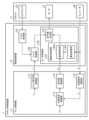
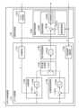
ロボット制御装置1は、ロボット2の位置姿勢と力を同時(並列)に制御する。ロボット制御装置1は、図1,2に示すように、メイン制御部(上位コントローラ)11、及び複数の関節制御部(下位コントローラ)12を備えている。関節制御部12は、ロボット2が有する関節毎に設けられている。なお、メイン制御部11と各関節制御部12との間は通信線により接続されている。BEST MODE FOR CARRYING OUT THE INVENTION Hereinafter, embodiments of the present invention will be described in detail with reference to the drawings.
1 and 2 are diagrams showing a configuration example of a
The
メイン制御部11は、各関節制御部12に指令値を出力することで、ロボット2全体を制御する。具体的には、メイン制御部11は、力の指令値及び位置姿勢の指令値並びにロボット2が有する関節毎の角度の現在値に基づいて、当該関節毎のトルクの指令値及び位置姿勢制御の指令値を演算する。図1,2では、位置姿勢制御の指令値は速度の指令値である。メイン制御部11は、図1に示すように、トルク指令値変換部111、位置姿勢演算部112、位置姿勢制御部113及び指令値変換部114を備えている。なお、メイン制御部11は、システムLSI(Large Scale Integration)等の処理回路、又はメモリ等に記憶されたプログラムを実行するCPU(Central Processing Unit)等により実現される。 The
トルク指令値変換部111は、力の指令値を、ロボット2が有する関節毎のトルクの指令値に変換する。トルク指令値変換部111は、係数乗算部1111を有している。係数乗算部1111は、力の指令値に対してヤコビ行列の転置行列を乗算する。力の指令値は直交座標系で表されており、トルク指令値変換部111は、力の指令値を関節座標系で表されたトルクの指令値に変換する。図2において、Frは力の指令値を表し、Jはヤコビ行列を表し、τrはトルクの指令値を表している。 The torque command
位置姿勢演算部112は、ロボット2が有する関節毎の角度の現在値に基づいて、ロボット2の位置姿勢の現在値を演算する。ロボット2が有する関節毎の角度は関節座標系で表されており、位置姿勢演算部112は、関節毎の角度を直交座標系で表された位置姿勢に変換する。なおロボット2が有する関節毎の角度の現在値は、当該関節毎に設けられたエンコーダ24により検出される。図2において、θは角度の現在値を表し、Xは位置姿勢の現在値を表している。 The position/
位置姿勢制御部113は、位置姿勢の指令値及び位置姿勢演算部112により演算された位置姿勢の現在値に基づいて、速度の指令値(位置姿勢制御の指令値)を演算する。位置姿勢制御部113は、偏差演算器1131及び係数乗算部1132を有している。 The position/
偏差演算器1131は、位置姿勢の指令値と位置姿勢の現在値との間の偏差を演算によって求める。
係数乗算部1132は、偏差演算器1131による演算結果の偏差に対してゲインを乗算することで、速度の指令値を得る。図2において、Xrは位置姿勢の指令値を表し、GZはゲインを表している。The
The
指令値変換部114は、位置姿勢制御部113により演算された速度の指令値を、ロボット2が有する関節毎の角速度の指令値に変換する。指令値変換部114は、係数乗算部1141を有している。係数乗算部1141は、位置姿勢制御部113により演算された速度の指令値に対してヤコビ行列の逆行列を乗算する。すなわち、指令値変換部114は、直交座標系で表された指令値を関節座標系で表された指令値に変換する。図2において、θ(ドット)rは角速度の指令値を表している。 The command
関節制御部12は、メイン制御部11からの指令に応じ、対応する関節に設けられたモータ21を制御する。具体的には、関節制御部12は、対応する関節でのトルクの現在値並びにメイン制御部11により演算されたトルクの指令値及び角速度の指令値(位置姿勢制御の指令値)に基づいて、対応する関節に設けられたモータ21に対する指令値を演算する。関節制御部12は、図1に示すように、トルク取得部121、トルク制御部122及びモータ制御部123を備えている。モータ制御部123は、関節角制御部124及び指令値合成部125を有している。 The
トルク取得部121は、対応する関節でのトルクの現在値を取得する。ロボット2が有する関節毎のトルクの現在値は、当該関節毎に設けられたトルクセンサ23により検出される。 The
トルク制御部122は、対応する関節でのトルクの現在値及びメイン制御部11により演算されたトルクの指令値に基づいて、トルク制御の指令値を演算する。トルク制御部122は、減算器1221及びPI制御部1222を有している。 The
減算器1221は、メイン制御部11により演算されたトルクの指令値から、トルク取得部121により取得されたトルクの現在値を減算する。
PI制御部1222は、減算器1221による減算結果に基づいてPI制御を行うことで、トルク制御の指令値を得る。The
The
関節角制御部124は、メイン制御部11により演算された角速度の指令値に基づいて、角速度制御の指令値を演算する。関節角制御部124は、速度変換部1241及び速度制御部1242を有している。速度制御部1242は、減算器1243及びPI制御部1244を有している。 The joint
速度変換部1241は、対応する関節での角度の現在値を角速度の現在値に変換する。 The
減算器1243は、メイン制御部11により演算された角速度の指令値から、速度変換部1241により得られた角速度の現在値を減算する。
PI制御部1244は、減算器1243による減算結果に基づいてPI制御を行うことで、角速度制御の指令値を得る。The
The
指令値合成部125は、トルク制御部122により演算されたトルク制御の指令値及び関節角制御部124により演算された角速度制御の指令値を合成する。図1では、指令値合成部125は、加算器1251を有する。加算器1251は、トルク制御部122により演算されたトルク制御の指令値と関節角制御部124により演算された角速度制御の指令値とを加算する。この指令値合成部125による合成結果である指令値(電流指令値)は、モータ21に出力される。 The
次に、図1,2に示す実施の形態1に係るロボット制御装置1の動作例について、図3を参照しながら説明する。
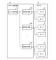
図1,2に示す実施の形態1に係るロボット制御装置1の動作例では、図3に示すように、まず、メイン制御部11は、力の指令値及び位置姿勢の指令値並びにロボット2が有する関節毎の角度の現在値に基づいて、当該関節毎のトルクの指令値及び角速度の指令値(位置姿勢制御の指令値)を演算する(ステップST301)。Next, an operation example of the
In the operation example of the
次いで、関節制御部12は、対応する関節でのトルクの現在値並びにメイン制御部11により演算されたトルクの指令値及び角速度の指令値に基づいて、対応する関節に設けられたモータ21に対する指令値を演算する(ステップST302)。 Next, based on the current torque value at the corresponding joint and the torque command value and the angular velocity command value calculated by the
次に、図1,2に示すメイン制御部11の動作例について、図4を参照しながら説明する。
図1,2に示すメイン制御部11の動作例では、図4に示すように、まず、トルク指令値変換部111は、力の指令値を、ロボット2が有する関節毎のトルクの指令値に変換する(ステップST401)。図1,2では、係数乗算部1111が、力の指令値に対してヤコビ行列の転置行列を乗算する。なお、ヤコビ行列はロボット2の関節の角度によって変わるので、適宜更新する必要がある。また、トルク取得部121が取得するトルクの現在値は通常、重力に起因するトルク成分を含むので、このトルク成分を相殺するようトルク指令値にこの重力起因トルク成分の推定値を重畳すると良い。Next, an operation example of the
In the operation example of the
また、位置姿勢演算部112は、ロボット2が有する関節毎の角度の現在値に基づいて、ロボット2の位置姿勢の現在値を演算する(ステップST402)。 Further, the position/
次いで、位置姿勢制御部113は、位置姿勢の指令値及び位置姿勢演算部112により演算された位置姿勢の現在値に基づいて、速度の指令値(位置姿勢制御の指令値)を演算する(ステップST403)。図1,2では、偏差演算器1131が、位置姿勢の指令値と位置姿勢の現在値との間の偏差を演算し、係数乗算部1132が、偏差演算器1131による演算結果の偏差に対してゲインを乗算することで、速度の指令値を得る。なお、位置の偏差は、指令値の座標値から現在値の座標値を減算することで得られる。姿勢の偏差は、現在値の姿勢から指令値の姿勢への回転変換を求めることで得ることができる。 Next, the position/
次いで、指令値変換部114は、位置姿勢制御部113により演算された速度の指令値を、ロボット2が有する関節毎の角速度の指令値に変換する(ステップST404)。図1,2では、係数乗算部1141が、位置姿勢制御部113により演算された速度の指令値に対してヤコビ行列の逆行列を乗算することで、関節毎の角速度の指令値を得る。 Next, the command
次に、図1,2に示す関節制御部12の動作例について、図5を参照しながら説明する。
図1,2に示す関節制御部12の動作例では、図5に示すように、まず、トルク取得部121は、対応する関節でのトルクの現在値を取得する(ステップST501)。Next, an operation example of the
In the operation example of the
次いで、トルク制御部122は、対応する関節でのトルクの現在値及びメイン制御部11により演算されたトルクの指令値に基づいて、トルク制御の指令値を演算する(ステップST502)。図1,2では、減算器1221が、メイン制御部11により演算されたトルクの指令値からトルク取得部121により取得されたトルクの現在値を減算し、PI制御部1222が、減算器1221による減算結果に基づいてPI制御を行うことで、トルク制御の指令値を得る。 Next, the
また、関節角制御部124は、メイン制御部11により演算された角速度の指令値に基づいて、角速度制御の指令値を演算する(ステップST503)。図1,2では、速度変換部1241が、対応する関節での角度の現在値を角速度の現在値に変換し、減算器1243が、メイン制御部11により演算された角速度の指令値から速度変換部1241により得られた角速度の現在値を減算し、PI制御部1244が、減算器1243による減算結果に基づいてPI制御を行うことで、角速度制御の指令値を得る。 Further, the joint
次いで、指令値合成部125は、トルク制御部122により演算されたトルク制御の指令値及び関節角制御部124により演算された角速度制御の指令値を合成する(ステップST504)。図1,2では、加算器1251が、トルク制御部122により演算されたトルク制御の指令値と関節角制御部124により演算された角速度制御の指令値とを加算する。この指令値合成部125による合成結果である指令値(電流指令値)は、モータ21に出力される。 Next, the
次に、実施の形態1に係るロボット制御装置1による効果について説明する。
上述したように、従来のロボット制御装置1bでは、メイン制御部11bでフィードバック系を構成している。すなわち、このロボット制御装置1bでは、ロボット2から物理的にも通信的にも距離のある構成要素でフィードバック制御演算を行うことになる。よって、トルクセンサ23によるトルクの検出からモータ21への指令値の入力までの遅延が長くなる。その結果、このロボット制御装置1では、不可避的にむだ時間が入り込む余地が多くなり、安定性を維持できるハイゲイン化を抑制する要因になる。また、むだ時間自体も、リード補償等でキャンセルできる要素ではないため、応答時間への悪影響は避けられない。Next, effects of the
As described above, in the conventional
これに対し、実施の形態1に係るロボット制御装置1のように、メイン制御部11で力制御に対する演算を実施するのではなく、関節制御部12でトルク制御に対する演算を実施することで、トルクセンサ23によるトルクの検出からモータ21への指令値の入力までの遅延が短くなり、むだ時間が入り込む余地を削減できる。すなわち、実施の形態1に係るロボット制御装置1は、安定性を維持できるコントローラのハイゲイン化に相当する調整(関節単位の1変数制御のゲイン調整)も可能になる。このように、実施の形態1に係るロボット制御装置1では、従来構成に対して力制御の性能(特に速応性)の向上が可能となる。 On the other hand, unlike the
図6は、実施の形態1に係るロボット制御装置1による効果を説明するための図である。図6Aは実施の形態1に係るロボット制御装置1を用いた場合でのシミュレーション結果の一例を示す図であり、図6Bは従来のロボット制御装置1bを用いた場合でのシミュレーション結果の一例を示す図である。図6では、ロボット2で物体をZ軸方向に押し付けた際のシミュレーション結果を示している。なお、ロボット2による押付け力の目標値は10[N]としている。図6A及び図6Bにおいて、横軸は時間[s]を示し、縦軸はロボット2によるZ軸方向への押付け力を示している。
この場合、図6Bに示すように、従来のロボット制御装置1bを用いた場合には、ロボット2によるZ軸方向への押付け力が目標値に整定するまでの時間(整定時間)が3.03[s]となっている。これに対し、図6Aに示すように、実施の形態1に係るロボット制御装置1を用いた場合には、整定時間が0.47[s]となっている。すなわち、実施の形態1に係るロボット制御装置1を用いた場合には、従来のロボット制御装置1bを用いた場合に対し、ロボット2によるZ軸方向への押付け力が短い時間で目標値に整定していることがわかる。FIG. 6 is a diagram for explaining the effects of the
In this case, as shown in FIG. 6B, when the conventional
また図6Bでは、従来のロボット制御装置1bにおける、力偏差の算出から速度指令値の算出までのゲインは、-2.0×10⁻³となる。これに対し、図6Aでは、実施の形態1に係るロボット制御装置1における、力偏差の算出から速度指令値の算出までのゲインに相当する等価ゲインは、-9.2×10⁻³となる。すなわち、実施の形態1に係るロボット制御装置1では、従来のロボット制御装置1bに対して高いゲインでの力制御が実現できていることがわかる。なお、実施の形態1に係るロボット制御装置1では、実際には力偏差から速度指令値を算出していないので、上記で示したゲインは実際のゲインではなく換算値である。In FIG. 6B, the gain from the calculation of the force deviation to the calculation of the speed command value in the conventional
なお、図1,2に示すロボット制御装置1では、速度制御に関するゲインを0にすることで単体のトルク制御を実現でき、また、トルク制御に関するゲインを0にすることで通常の速度制御を実現できる。 In the
以上のように、この実施の形態1によれば、ロボット制御装置1は、力の指令値及び位置姿勢の指令値並びにロボット2が有する関節毎の角度の現在値に基づいて、当該関節毎のトルクの指令値及び位置姿勢制御の指令値を演算するメイン制御部11と、ロボット2が有する関節毎に設けられ、対応する関節でのトルクの現在値並びにメイン制御部11により演算されたトルクの指令値及び位置姿勢制御の指令値に基づいて、対応する関節に設けられたモータ21に対する指令値を演算する関節制御部12とを備えた。これにより、実施の形態1に係るロボット制御装置1は、従来構成に対して力制御の性能を向上可能となる。 As described above, according to the first embodiment, the
なお、実施の形態1では関節角制御部124が関節制御部12に設けられた場合を示した。しかしながら、これに限らず、関節角制御部124はメイン制御部11に設けられていてもよい。例えば、ロボット2が低速で動作する場合等であれば、関節角制御部124がメイン制御部11に設けられていることによる影響は少ないと考えられる。
また、関節角制御部124は必須の構成ではなく、ロボット制御装置1から取除いてもよい。In addition, in
Also, the joint
実施の形態2.
実施の形態1では、関節制御部12において、メイン制御部11で演算された角速度の指令値(位置姿勢制御の指令値)を用いて角速度制御の指令値を演算し、その後、トルク制御の指令値及び角速度制御の指令値を合成する場合を示した。しかしながら、これに限らず、関節制御部12において、トルク制御の指令値及びメイン制御部11で演算された角速度の指令値(位置姿勢制御の指令値)を合成した後、その合成結果を用いて角速度制御の指令値を演算してもよい。
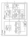
図7,8は実施の形態2に係るロボット制御装置1の構成例を示す図である。図7,8に示す実施の形態2に係るロボット制御装置1は、図1,2に示す実施の形態1に係るロボット制御装置1に対し、関節角制御部124及び指令値合成部125を指令値合成部126及び関節角制御部127に変更している。その他の構成は同様であり、同一の符号を付してその説明を省略する。
In the first embodiment, in the
7 and 8 are diagrams showing configuration examples of the
指令値合成部126は、メイン制御部11により演算された角速度の指令値(位置姿勢制御の指令値)及びトルク制御部122により演算されたトルク制御の指令値を合成する。図8では、指令値合成部126は、加算器1261を有する。加算器1261は、メイン制御部11により演算された角速度の指令値とトルク制御部122により演算されたトルク制御の指令値とを加算する。 The command
関節角制御部127は、指令値合成部126による合成結果に基づいて、角速度制御の指令値を演算する。関節角制御部127は、速度変換部1271及び速度制御部1272を有している。速度制御部1272は、減算器1273及びPI制御部1274を有している。 The joint
速度変換部1271は、対応する関節での角度の現在値を角速度の現在値に変換する。 The
減算器1273は、指令値合成部126による合成結果から、速度変換部1271により得られた角速度の現在値を減算する。
PI制御部1274は、減算器1273による減算結果に基づいてPI制御を行うことで、角速度制御の指令値を得る。
この関節角制御部127により演算された角速度制御の指令値(電流指令値)は、対応する関節に設けられたモータ21に出力される。A
The
The angular velocity control command value (current command value) calculated by the joint
このように、実施の形態2に係るロボット制御装置1では、位置姿勢制御の指令値及びトルク制御の指令値を合成し、その合成結果に基づいて角速度制御を実施する。この実施の形態2に係るロボット制御装置1についても、実施の形態1に係るロボット制御装置1と同様の効果が得られる。また、実施の形態2に係るロボット制御装置1は、従来のコンプライアンス制御に近い対応関係となる。 As described above, in the
また、本願発明はその発明の範囲内において、各実施の形態の自由な組合わせ、或いは各実施の形態の任意の構成要素の変形、若しくは各実施の形態において任意の構成要素の省略が可能である。例えば、実施の形態1,2では関節角制御部が速度制御を行う例を用いて説明したが、加速度又は電流等の他の物理量の制御を介して位置姿勢の制御を行うことも可能である。 In addition, within the scope of the present invention, it is possible to freely combine each embodiment, modify any component of each embodiment, or omit any component in each embodiment. be. For example, in
1 ロボット制御装置
2 ロボット
11 メイン制御部
12 関節制御部
21 モータ
22 センサ
23 トルクセンサ
24 エンコーダ
111 トルク指令値変換部
112 位置姿勢演算部
113 位置姿勢制御部
114 指令値変換部
121 トルク取得部
122 トルク制御部
123 モータ制御部
124 関節角制御部
125 指令値合成部
126 指令値合成部
127 関節角制御部
1111 係数乗算部
1131 偏差演算器
1132 係数乗算部
1141 係数乗算部
1221 減算器
1222 PI制御部
1241 速度変換部
1242 速度制御部
1243 減算器
1244 PI制御部
1251 加算器
1261 加算器
1271 速度変換部
1272 速度制御部
1273 減算器
1274 PI制御部1
Claims (4)
Translated fromJapanese前記ロボットが複数有する関節毎に設けられ、関節毎のトルクの現在値を検知可能な手段から取得された対応する関節でのトルクの現在値並びに前記メイン制御部により演算されたトルクの指令値及び位置姿勢制御の指令値に基づいて、対応する関節に設けられたモータに対する指令値を演算する関節制御部とを備え、
前記メイン制御部は、
力の指令値を、ロボットが複数有する関節毎のトルクの指令値に変換するトルク指令値変換部を有し、
前記関節制御部は、
対応する関節でのトルクの現在値及び前記メイン制御部により演算されたトルクの指令値に基づいて、トルク制御の指令値を演算するトルク制御部と、
前記トルク制御部により演算されたトルク制御の指令値と、前記メイン制御部により演算された位置姿勢制御の指令値又は前記メイン制御部により演算された位置姿勢制御の指令値に基づいて速度、加速度、電流又はトルクの制御の指令値を演算する関節角制御部により演算された制御の指令値とを合成する指令値合成部とを有する
ことを特徴とするロボット制御装置。a main control unit that calculates a torque command value and a position/attitude control command value for each joint based on a force command value, a position/posture command value, and a current angle value for each of a plurality of joints of the robot;
A current value of torque at the corresponding joint, which is provided for each of the plurality of joints of the robot and is obtained from means capable of detecting the current value of torque at each joint, and a torque command value calculated by the main control unit; a joint control unit that calculates a command value for a motor provided at a corresponding joint based on a command value for position/orientation control;
The main control unit
a torque command value conversion unit that converts a force command value into a torque command value for each of a plurality of joints of the robot;
The joint control unit is
a torque control unit that calculates a command value for torque control based on the current torque value at the corresponding joint and the torque command value calculated by the main control unit;
Velocity and acceleration based on the torque control command value calculated by the torque control unit, the position/attitude control command value calculated by the main control unit, or the position/attitude control command value calculated by the main control unit and a command value synthesizing unit for synthesizing the control command value calculated by the joint angle control unit for calculating a command value for current or torque control.
ことを特徴とする請求項1記載のロボット制御装置。The command value synthesizing unit obtains a command value for the motor by synthesizing the position/orientation control command value calculated by the main control unit and the torque control command value calculated by the torque control unit. 2. The robot control device according to claim 1.
前記関節角制御部は、前記メイン制御部により演算された位置姿勢制御の指令値に基づいて、角速度制御の指令値を演算し、
前記指令値合成部は、前記トルク制御部により演算されたトルク制御の指令値及び前記関節角制御部により演算された角速度制御の指令値を合成することで、前記モータに対する指令値を得る
ことを特徴とする請求項1記載のロボット制御装置。The joint control section has the joint angle control section,
The jointangle control unit calculates a command value for angular velocity control based on the command value for position/orientation control calculated by the main control unit,
The command value synthesis unit obtains a command value for the motor by synthesizing the torque control command value calculated by the torque control unit and the angular velocity control command value calculated by the joint angle control unit. 2. The robot control device according to claim 1.
前記メイン制御部は、力の指令値及び位置姿勢の指令値並びにロボットが複数有する関節毎の角度の現在値に基づいて、当該関節毎のトルクの指令値及び位置姿勢制御の指令値を演算し、
前記関節制御部は、関節毎のトルクの現在値を検知可能な手段から取得された対応する関節でのトルクの現在値並びに前記メイン制御部により演算されたトルクの指令値及び位置姿勢制御の指令値に基づいて、対応する関節に設けられたモータに対する指令値を演算し、
前記メイン制御部は、
力の指令値を、ロボットが複数有する関節毎のトルクの指令値に変換するトルク指令値変換部を有し、
前記関節制御部は、
対応する関節でのトルクの現在値及び前記メイン制御部により演算されたトルクの指令値に基づいて、トルク制御の指令値を演算するトルク制御部と、
前記トルク制御部により演算されたトルク制御の指令値と、前記メイン制御部により演算された位置姿勢制御の指令値又は前記メイン制御部により演算された位置姿勢制御の指令値に基づいて速度、加速度、電流又はトルクの制御の指令値を演算する関節角制御部により演算された制御の指令値とを合成する指令値合成部とを有する
ことを特徴とするロボット制御方法。A robot control method by a robot control device including a main control unit and a joint control unit provided for each of a plurality of joints of the robot,
The main control unit calculates a torque command value and a position/attitude control command value for each joint based on a force command value, a position/posture command value, and a current angle value for each of a plurality of joints of the robot. ,
The joint control unit controls the current torque values at the corresponding joints obtained from means capable of detecting the current torque values of the joints, the torque command values calculated by the main control unit, and the position/orientation control commands. Based on the value, calculate the command value for the motor provided in the corresponding joint,
The main control unit
a torque command value conversion unit that converts a force command value into a torque command value for each of a plurality of joints of the robot;
The joint control unit is
a torque control unit that calculates a command value for torque control based on the current torque value at the corresponding joint and the torque command value calculated by the main control unit;
Velocity and acceleration based on the torque control command value calculated by the torque control unit, the position/attitude control command value calculated by the main control unit, or the position/attitude control command value calculated by the main control unit and a command value synthesizing unit for synthesizing the control command value calculated by the joint angle control unit for calculating the current or torque control command value.
Priority Applications (3)
| Application Number | Priority Date | Filing Date | Title |
|---|---|---|---|
| JP2019043626AJP7300854B2 (en) | 2019-03-11 | 2019-03-11 | ROBOT CONTROL DEVICE AND ROBOT CONTROL METHOD |
| CN202080016903.2ACN113508011A (en) | 2019-03-11 | 2020-02-27 | Robot control device and robot control method |
| PCT/JP2020/008100WO2020184203A1 (en) | 2019-03-11 | 2020-02-27 | Robot control device and robot control method |
Applications Claiming Priority (1)
| Application Number | Priority Date | Filing Date | Title |
|---|---|---|---|
| JP2019043626AJP7300854B2 (en) | 2019-03-11 | 2019-03-11 | ROBOT CONTROL DEVICE AND ROBOT CONTROL METHOD |
Publications (2)
| Publication Number | Publication Date |
|---|---|
| JP2020146765A JP2020146765A (en) | 2020-09-17 |
| JP7300854B2true JP7300854B2 (en) | 2023-06-30 |
Family
ID=72426801
Family Applications (1)
| Application Number | Title | Priority Date | Filing Date |
|---|---|---|---|
| JP2019043626AActiveJP7300854B2 (en) | 2019-03-11 | 2019-03-11 | ROBOT CONTROL DEVICE AND ROBOT CONTROL METHOD |
Country Status (3)
| Country | Link |
|---|---|
| JP (1) | JP7300854B2 (en) |
| CN (1) | CN113508011A (en) |
| WO (1) | WO2020184203A1 (en) |
Families Citing this family (1)
| Publication number | Priority date | Publication date | Assignee | Title |
|---|---|---|---|---|
| JP7529599B2 (en)* | 2021-03-24 | 2024-08-06 | 本田技研工業株式会社 | robot |
Citations (2)
| Publication number | Priority date | Publication date | Assignee | Title |
|---|---|---|---|---|
| JP2016168650A (en) | 2015-03-13 | 2016-09-23 | キヤノン株式会社 | Robot device, robot control method, program, and storage medium |
| JP2017158417A (en) | 2016-02-29 | 2017-09-07 | 株式会社安川電機 | Motor control system, robot system, and motor control system communication method |
Family Cites Families (5)
| Publication number | Priority date | Publication date | Assignee | Title |
|---|---|---|---|---|
| JPH03214303A (en)* | 1990-01-19 | 1991-09-19 | Citizen Watch Co Ltd | Positioning controller and track data teaching method |
| JP2669274B2 (en)* | 1992-07-06 | 1997-10-27 | 三菱電機株式会社 | Robot control device |
| JP3324298B2 (en)* | 1994-10-19 | 2002-09-17 | 株式会社豊田中央研究所 | Manipulator control device |
| JPH0944253A (en)* | 1995-08-03 | 1997-02-14 | Toyota Central Res & Dev Lab Inc | Drive switching control device |
| JP3529575B2 (en)* | 1997-02-17 | 2004-05-24 | 株式会社東芝 | Force control robot and control method thereof |
- 2019
- 2019-03-11JPJP2019043626Apatent/JP7300854B2/enactiveActive
- 2020
- 2020-02-27WOPCT/JP2020/008100patent/WO2020184203A1/ennot_activeCeased
- 2020-02-27CNCN202080016903.2Apatent/CN113508011A/ennot_activeWithdrawn
Patent Citations (2)
| Publication number | Priority date | Publication date | Assignee | Title |
|---|---|---|---|---|
| JP2016168650A (en) | 2015-03-13 | 2016-09-23 | キヤノン株式会社 | Robot device, robot control method, program, and storage medium |
| JP2017158417A (en) | 2016-02-29 | 2017-09-07 | 株式会社安川電機 | Motor control system, robot system, and motor control system communication method |
Also Published As
| Publication number | Publication date |
|---|---|
| CN113508011A (en) | 2021-10-15 |
| WO2020184203A1 (en) | 2020-09-17 |
| JP2020146765A (en) | 2020-09-17 |
Similar Documents
| Publication | Publication Date | Title |
|---|---|---|
| US10751874B2 (en) | Method of teaching robot and robotic arm control device | |
| JP4896276B2 (en) | ROBOT, ROBOT CONTROL DEVICE, CONTROL METHOD, AND CONTROL PROGRAM | |
| JP5327722B2 (en) | Robot load estimation apparatus and load estimation method | |
| US20180207797A1 (en) | Control system having learning control function and control method | |
| US20180345492A1 (en) | Direct teaching method of robot | |
| WO2001038048A1 (en) | Robot controller | |
| JP2010537831A (en) | Inverse kinematics | |
| CN109656132B (en) | Finite time coordination control method for space robot | |
| JP6898649B2 (en) | Vibration control device, vibration control method, vibration control system, program and recording medium | |
| JP2014136260A (en) | Control device | |
| JP2021109259A (en) | Robot control device and robot control method | |
| JP4192780B2 (en) | Robot control device | |
| US9676100B2 (en) | Control apparatus of robot, robot, and program thereof | |
| JP7300854B2 (en) | ROBOT CONTROL DEVICE AND ROBOT CONTROL METHOD | |
| CN108536096A (en) | The three-D profile control method and device of task based access control polar coordinate system | |
| JP4587052B2 (en) | POSITION CONTROL DEVICE, POSITION CONTROL METHOD, AND POSITION CONTROL PROGRAM | |
| JP7273627B2 (en) | ROBOT CONTROL DEVICE AND ROBOT CONTROL METHOD | |
| JP4134369B2 (en) | Robot control device | |
| JP6237039B2 (en) | Robot control apparatus and robot control method | |
| CN114505849A (en) | Robot control device and robot control method | |
| Huynh et al. | Dynamic Hybrid Filter for Vision‐Based Pose Estimation of a Hexa Parallel Robot | |
| CN114734437B (en) | Robot joint control method and device | |
| US8670869B2 (en) | Robot controller | |
| JP5057224B2 (en) | Mobile robot controller | |
| Lauer et al. | Force-Controlled On-Site Assembly Using Pose-Dependent Stiffness of Large-Scale Manipulators |
Legal Events
| Date | Code | Title | Description |
|---|---|---|---|
| A621 | Written request for application examination | Free format text:JAPANESE INTERMEDIATE CODE: A621 Effective date:20211223 | |
| A131 | Notification of reasons for refusal | Free format text:JAPANESE INTERMEDIATE CODE: A131 Effective date:20220802 | |
| A521 | Request for written amendment filed | Free format text:JAPANESE INTERMEDIATE CODE: A523 Effective date:20220922 | |
| RD02 | Notification of acceptance of power of attorney | Free format text:JAPANESE INTERMEDIATE CODE: A7422 Effective date:20220922 | |
| A131 | Notification of reasons for refusal | Free format text:JAPANESE INTERMEDIATE CODE: A131 Effective date:20230124 | |
| A521 | Request for written amendment filed | Free format text:JAPANESE INTERMEDIATE CODE: A523 Effective date:20230323 | |
| A131 | Notification of reasons for refusal | Free format text:JAPANESE INTERMEDIATE CODE: A131 Effective date:20230404 | |
| A521 | Request for written amendment filed | Free format text:JAPANESE INTERMEDIATE CODE: A523 Effective date:20230517 | |
| TRDD | Decision of grant or rejection written | ||
| A01 | Written decision to grant a patent or to grant a registration (utility model) | Free format text:JAPANESE INTERMEDIATE CODE: A01 Effective date:20230523 | |
| A61 | First payment of annual fees (during grant procedure) | Free format text:JAPANESE INTERMEDIATE CODE: A61 Effective date:20230620 | |
| R150 | Certificate of patent or registration of utility model | Ref document number:7300854 Country of ref document:JP Free format text:JAPANESE INTERMEDIATE CODE: R150 |