JP7299912B2 - Foam pump, refill unit, and dispenser with differential bore sackback mechanism - Google Patents
Foam pump, refill unit, and dispenser with differential bore sackback mechanismDownload PDFInfo
- Publication number
- JP7299912B2 JP7299912B2JP2020552228AJP2020552228AJP7299912B2JP 7299912 B2JP7299912 B2JP 7299912B2JP 2020552228 AJP2020552228 AJP 2020552228AJP 2020552228 AJP2020552228 AJP 2020552228AJP 7299912 B2JP7299912 B2JP 7299912B2
- Authority
- JP
- Japan
- Prior art keywords
- bore
- suckback
- piston
- chamber
- foam
- Prior art date
- Legal status (The legal status is an assumption and is not a legal conclusion. Google has not performed a legal analysis and makes no representation as to the accuracy of the status listed.)
- Active
Links
- 239000006260foamSubstances0.000titleclaimsdescription110
- 239000007788liquidSubstances0.000claimsdescription75
- 239000000203mixtureSubstances0.000claimsdescription27
- 239000012530fluidSubstances0.000claimsdescription26
- 238000011144upstream manufacturingMethods0.000claimsdescription6
- 238000004891communicationMethods0.000claimsdescription4
- 230000009977dual effectEffects0.000description68
- 238000005187foamingMethods0.000description5
- 238000005336crackingMethods0.000description4
- 238000005086pumpingMethods0.000description3
- 239000000344soapSubstances0.000description3
- 238000010586diagramMethods0.000description2
- 239000006210lotionSubstances0.000description2
- -1sanitizersSubstances0.000description2
- 235000001674Agaricus brunnescensNutrition0.000description1
- 241000272525Anas platyrhynchosSpecies0.000description1
- LFQSCWFLJHTTHZ-UHFFFAOYSA-NEthanolChemical compoundCCOLFQSCWFLJHTTHZ-UHFFFAOYSA-N0.000description1
- 239000000853adhesiveSubstances0.000description1
- 230000001070adhesive effectEffects0.000description1
- 239000000645desinfectantSubstances0.000description1
- 235000013305foodNutrition0.000description1
- 230000002401inhibitory effectEffects0.000description1
- 230000000670limiting effectEffects0.000description1
- 230000014759maintenance of locationEffects0.000description1
- 238000000034methodMethods0.000description1
- 238000012986modificationMethods0.000description1
- 230000004048modificationEffects0.000description1
- 230000036961partial effectEffects0.000description1
- 230000000717retained effectEffects0.000description1
Images


Classifications
- A—HUMAN NECESSITIES
- A47—FURNITURE; DOMESTIC ARTICLES OR APPLIANCES; COFFEE MILLS; SPICE MILLS; SUCTION CLEANERS IN GENERAL
- A47K—SANITARY EQUIPMENT NOT OTHERWISE PROVIDED FOR; TOILET ACCESSORIES
- A47K5/00—Holders or dispensers for soap, toothpaste, or the like
- A47K5/06—Dispensers for soap
- A47K5/12—Dispensers for soap for liquid or pasty soap
- A47K5/1202—Dispensers for soap for liquid or pasty soap dispensing dosed volume
- A47K5/1204—Dispensers for soap for liquid or pasty soap dispensing dosed volume by means of a rigid dispensing chamber and pistons
- A47K5/1207—Dispensing from the bottom of the dispenser with a vertical piston
- A—HUMAN NECESSITIES
- A47—FURNITURE; DOMESTIC ARTICLES OR APPLIANCES; COFFEE MILLS; SPICE MILLS; SUCTION CLEANERS IN GENERAL
- A47K—SANITARY EQUIPMENT NOT OTHERWISE PROVIDED FOR; TOILET ACCESSORIES
- A47K5/00—Holders or dispensers for soap, toothpaste, or the like
- A47K5/06—Dispensers for soap
- A47K5/12—Dispensers for soap for liquid or pasty soap
- A47K5/1202—Dispensers for soap for liquid or pasty soap dispensing dosed volume
- A47K5/1208—Dispensers for soap for liquid or pasty soap dispensing dosed volume by means of a flexible dispensing chamber
- A—HUMAN NECESSITIES
- A47—FURNITURE; DOMESTIC ARTICLES OR APPLIANCES; COFFEE MILLS; SPICE MILLS; SUCTION CLEANERS IN GENERAL
- A47K—SANITARY EQUIPMENT NOT OTHERWISE PROVIDED FOR; TOILET ACCESSORIES
- A47K5/00—Holders or dispensers for soap, toothpaste, or the like
- A47K5/06—Dispensers for soap
- A47K5/12—Dispensers for soap for liquid or pasty soap
- A47K5/1211—Dispensers for soap for liquid or pasty soap using pressure on soap, e.g. with piston
- A—HUMAN NECESSITIES
- A47—FURNITURE; DOMESTIC ARTICLES OR APPLIANCES; COFFEE MILLS; SPICE MILLS; SUCTION CLEANERS IN GENERAL
- A47K—SANITARY EQUIPMENT NOT OTHERWISE PROVIDED FOR; TOILET ACCESSORIES
- A47K5/00—Holders or dispensers for soap, toothpaste, or the like
- A47K5/14—Foam or lather making devices
- A47K5/16—Foam or lather making devices with mechanical drive
- B—PERFORMING OPERATIONS; TRANSPORTING
- B05—SPRAYING OR ATOMISING IN GENERAL; APPLYING FLUENT MATERIALS TO SURFACES, IN GENERAL
- B05B—SPRAYING APPARATUS; ATOMISING APPARATUS; NOZZLES
- B05B12/00—Arrangements for controlling delivery; Arrangements for controlling the spray area
- B05B12/08—Arrangements for controlling delivery; Arrangements for controlling the spray area responsive to condition of liquid or other fluent material to be discharged, of ambient medium or of target ; responsive to condition of spray devices or of supply means, e.g. pipes, pumps or their drive means
- B05B12/12—Arrangements for controlling delivery; Arrangements for controlling the spray area responsive to condition of liquid or other fluent material to be discharged, of ambient medium or of target ; responsive to condition of spray devices or of supply means, e.g. pipes, pumps or their drive means responsive to conditions of ambient medium or target, e.g. humidity, temperature position or movement of the target relative to the spray apparatus
- B05B12/122—Arrangements for controlling delivery; Arrangements for controlling the spray area responsive to condition of liquid or other fluent material to be discharged, of ambient medium or of target ; responsive to condition of spray devices or of supply means, e.g. pipes, pumps or their drive means responsive to conditions of ambient medium or target, e.g. humidity, temperature position or movement of the target relative to the spray apparatus responsive to presence or shape of target
- B—PERFORMING OPERATIONS; TRANSPORTING
- B05—SPRAYING OR ATOMISING IN GENERAL; APPLYING FLUENT MATERIALS TO SURFACES, IN GENERAL
- B05B—SPRAYING APPARATUS; ATOMISING APPARATUS; NOZZLES
- B05B7/00—Spraying apparatus for discharge of liquids or other fluent materials from two or more sources, e.g. of liquid and air, of powder and gas
- B05B7/0018—Spraying apparatus for discharge of liquids or other fluent materials from two or more sources, e.g. of liquid and air, of powder and gas with devices for making foam
- B05B7/005—Spraying apparatus for discharge of liquids or other fluent materials from two or more sources, e.g. of liquid and air, of powder and gas with devices for making foam wherein ambient air is aspirated by a liquid flow
- B05B7/0056—Spraying apparatus for discharge of liquids or other fluent materials from two or more sources, e.g. of liquid and air, of powder and gas with devices for making foam wherein ambient air is aspirated by a liquid flow with disturbing means promoting mixing, e.g. balls, crowns
- B05B7/0062—Spraying apparatus for discharge of liquids or other fluent materials from two or more sources, e.g. of liquid and air, of powder and gas with devices for making foam wherein ambient air is aspirated by a liquid flow with disturbing means promoting mixing, e.g. balls, crowns including sieves, porous members or the like
- F—MECHANICAL ENGINEERING; LIGHTING; HEATING; WEAPONS; BLASTING
- F04—POSITIVE - DISPLACEMENT MACHINES FOR LIQUIDS; PUMPS FOR LIQUIDS OR ELASTIC FLUIDS
- F04B—POSITIVE-DISPLACEMENT MACHINES FOR LIQUIDS; PUMPS
- F04B13/00—Pumps specially modified to deliver fixed or variable measured quantities
- F—MECHANICAL ENGINEERING; LIGHTING; HEATING; WEAPONS; BLASTING
- F04—POSITIVE - DISPLACEMENT MACHINES FOR LIQUIDS; PUMPS FOR LIQUIDS OR ELASTIC FLUIDS
- F04B—POSITIVE-DISPLACEMENT MACHINES FOR LIQUIDS; PUMPS
- F04B15/00—Pumps adapted to handle specific fluids, e.g. by selection of specific materials for pumps or pump parts
- F—MECHANICAL ENGINEERING; LIGHTING; HEATING; WEAPONS; BLASTING
- F04—POSITIVE - DISPLACEMENT MACHINES FOR LIQUIDS; PUMPS FOR LIQUIDS OR ELASTIC FLUIDS
- F04B—POSITIVE-DISPLACEMENT MACHINES FOR LIQUIDS; PUMPS
- F04B43/00—Machines, pumps, or pumping installations having flexible working members
- F04B43/02—Machines, pumps, or pumping installations having flexible working members having plate-like flexible members, e.g. diaphragms
- F04B43/025—Machines, pumps, or pumping installations having flexible working members having plate-like flexible members, e.g. diaphragms two or more plate-like pumping members in parallel
- F04B43/026—Machines, pumps, or pumping installations having flexible working members having plate-like flexible members, e.g. diaphragms two or more plate-like pumping members in parallel each plate-like pumping flexible member working in its own pumping chamber
- F—MECHANICAL ENGINEERING; LIGHTING; HEATING; WEAPONS; BLASTING
- F04—POSITIVE - DISPLACEMENT MACHINES FOR LIQUIDS; PUMPS FOR LIQUIDS OR ELASTIC FLUIDS
- F04B—POSITIVE-DISPLACEMENT MACHINES FOR LIQUIDS; PUMPS
- F04B53/00—Component parts, details or accessories not provided for in, or of interest apart from, groups F04B1/00 - F04B23/00 or F04B39/00 - F04B47/00
- F04B53/14—Pistons, piston-rods or piston-rod connections
- G—PHYSICS
- G01—MEASURING; TESTING
- G01F—MEASURING VOLUME, VOLUME FLOW, MASS FLOW OR LIQUID LEVEL; METERING BY VOLUME
- G01F11/00—Apparatus requiring external operation adapted at each repeated and identical operation to measure and separate a predetermined volume of fluid or fluent solid material from a supply or container, without regard to weight, and to deliver it
- G01F11/02—Apparatus requiring external operation adapted at each repeated and identical operation to measure and separate a predetermined volume of fluid or fluent solid material from a supply or container, without regard to weight, and to deliver it with measuring chambers which expand or contract during measurement
- G01F11/08—Apparatus requiring external operation adapted at each repeated and identical operation to measure and separate a predetermined volume of fluid or fluent solid material from a supply or container, without regard to weight, and to deliver it with measuring chambers which expand or contract during measurement of the diaphragm or bellows type
- B—PERFORMING OPERATIONS; TRANSPORTING
- B05—SPRAYING OR ATOMISING IN GENERAL; APPLYING FLUENT MATERIALS TO SURFACES, IN GENERAL
- B05B—SPRAYING APPARATUS; ATOMISING APPARATUS; NOZZLES
- B05B11/00—Single-unit hand-held apparatus in which flow of contents is produced by the muscular force of the operator at the moment of use
- B05B11/01—Single-unit hand-held apparatus in which flow of contents is produced by the muscular force of the operator at the moment of use characterised by the means producing the flow
- B05B11/10—Pump arrangements for transferring the contents from the container to a pump chamber by a sucking effect and forcing the contents out through the dispensing nozzle
- B05B11/1097—Pump arrangements for transferring the contents from the container to a pump chamber by a sucking effect and forcing the contents out through the dispensing nozzle with means for sucking back the liquid or other fluent material in the nozzle after a dispensing stroke
Landscapes
- Engineering & Computer Science (AREA)
- Health & Medical Sciences (AREA)
- Public Health (AREA)
- Mechanical Engineering (AREA)
- General Engineering & Computer Science (AREA)
- Physics & Mathematics (AREA)
- Fluid Mechanics (AREA)
- General Physics & Mathematics (AREA)
- Containers And Packaging Bodies Having A Special Means To Remove Contents (AREA)
- Details Of Reciprocating Pumps (AREA)
- Closures For Containers (AREA)
- Nozzles (AREA)
Description
Translated fromJapanese関連出願
本出願は、2018年3月28日に出願され、「FOAM PUMPS,REFILL UNITS AND DISPENSERS WITH DIFFERENTIAL BORE SUCK-BACK MECHANISM」と題された米国仮出願番号第62/649,069号の優先権および利益を主張し、参照によりその全体が本明細書に組み込まれる。RELATED APPLICATIONS This application has priority to U.S. Provisional Application No. 62/649,069, filed March 28, 2018 and entitled "FOAM PUMPS, REFILL UNITS AND DISPENSERS WITH DIFFERENTIAL BORE SUCK-BACK MECHANISM." and claim benefit, which is incorporated herein by reference in its entirety.
様々な実施形態は、一般に、ポンプ、発泡体ディスペンサーのための再充填ユニット、およびディスペンサーシステムに関し、より具体的には、発泡体の分注時の滴下を防止する改善された方法を有するシステムおよびディスペンサーに関する。 Various embodiments relate generally to pumps, refill units for foam dispensers, and dispenser systems, and more particularly to systems with improved methods of preventing dripping when dispensing foam and Regarding dispensers.
例えば、液体石鹸および消毒剤ディスペンサーなどの液体ディスペンサーシステムは、ディスペンサーの作動に伴い所定量の流体をユーザーに提供する。さらに、例えば、空気を液体中に注入して液体および気泡の発泡混合物を作り出すことにより、流体を泡の形態で分注することが望ましいことがある。例えば、アルコールベースの液体などの一部の液体は、発泡に困難であり、混合が強化される必要がある。発泡体を生成するポンプは、発泡体カートリッジを通して液体と空気との混合物をポンピングすることによって発泡体を形成しうる。分注後、残留発泡体は、液体に戻る傾向があり、発泡体カートリッジから滴下する。ユーザーが一定量の発泡体を受け、ポンプ出口の下から手を外した後、残留液体がポンプから滴下することを防ぐ発泡体ポンプを有することが望ましい。 For example, liquid dispenser systems, such as liquid soap and sanitizer dispensers, provide a user with a predetermined amount of fluid upon actuation of the dispenser. Additionally, it may be desirable to dispense the fluid in foam form, for example, by injecting air into the liquid to create a foamed mixture of liquid and foam. For example, some liquids, such as alcohol-based liquids, are difficult to foam and require enhanced mixing. A foam-producing pump may form foam by pumping a mixture of liquid and air through a foam cartridge. After dispensing, residual foam tends to revert to liquid and drips out of the foam cartridge. It is desirable to have a foam pump that prevents residual liquid from dripping from the pump after the user receives a dose of foam and removes his or her hand from under the pump outlet.
本出願は、既存の発泡体カートリッジと比較して、使用後の滴下が少ない改善された発泡体の品質を有する、例示的な発泡体発生ポンプおよび分注ポンプを開示する。しかし、本発明の概念は、発泡体分注システムに限定されず、石鹸、消毒剤、およびローションを分注するための液体ポンプに適用されうる。さらに、本発明の概念は、食品分注システム、接着剤分注システムおよびこれに類するものに適用されうる。例示的な実施形態のこれらおよびその他の態様は、様々な例示的な実施形態の原理を例として示す添付図面と併せて、以下の詳細な説明から明らかになるであろう。 The present application discloses exemplary foam generation and dispensing pumps having improved foam quality with less dripping after use compared to existing foam cartridges. However, the concepts of the present invention are not limited to foam dispensing systems, but can be applied to liquid pumps for dispensing soaps, sanitizers, and lotions. Additionally, the concepts of the present invention can be applied to food dispensing systems, adhesive dispensing systems and the like. These and other aspects of illustrative embodiments will become apparent from the following detailed description, taken in conjunction with the accompanying drawings, which illustrate by way of example the principles of various illustrative embodiments.
液だれ防止発泡体ディスペンサーおよびシステムを提供するための例示的なシステムが本明細書に開示されている。発泡体を分配するための例示的なシステムは、発泡性液体を保持する容器と、発泡性液体を空気と組み合わせて発泡体混合物を形成するためのポンプと、サックバックデバイス(suck-back device)とを含む。サックバックデバイスはハウジングを有する。ハウジングは、第一の直径を有する小さいボアを有する上流部分と、第二の直径を有する大きいボアを有する下流部分とを有する。第一の直径は第二の直径よりも小さい。サックバック機構は、小さいボア内で往復する第一のピストンと、大きいボア内で往復する第二のピストンとを有する、デュアルボディピストンを含む。上流位置でのデュアルボディピストンを付勢するための付勢部材も含まれる。さらに、デュアルボディピストンに近接して位置する流量制限器が含まれる。大きいボアおよび第二のピストンによって少なくとも部分的に形成されたサックバックチャンバー、およびサックバックチャンバー内に位置する発泡体出口も提供される。流量制限器は、サックバックデバイスへ流れる流体がサックバックチャンバーを圧縮させ、流体流が停止すると、付勢部材がサックバックチャンバーを拡張させ、残留発泡体をサックバックチャンバーに吸い戻すように構成される。 An exemplary system for providing a non-drip foam dispenser and system is disclosed herein. An exemplary system for dispensing foam includes a container holding a foamable liquid, a pump for combining the foamable liquid with air to form a foam mixture, and a suck-back device. including. The suckback device has a housing. The housing has an upstream portion with a small bore having a first diameter and a downstream portion with a large bore having a second diameter. The first diameter is smaller than the second diameter. The suckback mechanism includes a dual body piston having a first piston that reciprocates within a small bore and a second piston that reciprocates within a large bore. A biasing member is also included for biasing the dual body piston in the upstream position. Also included is a flow restrictor located proximate to the dual body piston. A suckback chamber defined at least in part by the large bore and the second piston, and a foam outlet located within the suckback chamber are also provided. The flow restrictor is configured such that fluid flowing to the suckback device compresses the suckback chamber, and when fluid flow stops, the biasing member expands the suckback chamber and sucks residual foam back into the suckback chamber. be.
発泡体ディスペンサー用の例示的な差動ボアサックバックデバイスは、第一の直径を有する小さいボアを有する上流部分と、第二の直径を有する大きいボアを有する下流部分とを有するハウジングを含み、第一の直径は第二の直径よりも小さい。また、小さいボア内で往復する第一のピストンと、大きいボア内で往復する第二のピストンとを有するデュアルボディピストン、上流位置でデュアルボディピストンを付勢するための付勢部材、デュアルボディピストンの近位に位置する流量制限器、大きいボアおよび第二のピストンによって少なくとも部分的に形成されるサックバックチャンバー、および発泡体出口も含まれる。流量制限器は、サックバックデバイスへの流体流がサックバックチャンバーを圧縮させ、流体流が停止すると、付勢部材がサックバックチャンバーを拡張させ、残留発泡体をサックバックチャンバーに吸い戻すように構成される。 An exemplary differential bore sackback device for a foam dispenser includes a housing having an upstream portion having a small bore having a first diameter and a downstream portion having a large bore having a second diameter; The first diameter is smaller than the second diameter. Also, a dual body piston having a first piston that reciprocates within a small bore and a second piston that reciprocates within a large bore; a biasing member for biasing the dual body piston at an upstream position; a dual body piston; Also included is a flow restrictor located proximal to the body, a suckback chamber defined at least in part by the large bore and the second piston, and a foam outlet. The flow restrictor is configured such that fluid flow to the suckback device compresses the suckback chamber, and when fluid flow stops, the biasing member expands the suckback chamber and sucks residual foam back into the suckback chamber. be done.
別の例示的な差動ボアサックバックデバイスは、第一の直径を有する第一のボアおよび第二の直径を有する第二のボアを有するハウジングを含み、第一の直径は第二の直径よりも小さく、第一のピストンシールは、第一のボアの壁と接触するようにサイズ決めされ、第二のピストンシールは第二のボアの壁と接触するようにサイズ決めされる。第一のピストンシールは、流量制限器を含むボディに接続される。ピストンは、付勢部材によって上に付勢される。第二のボアおよび第二のピストンによって少なくとも部分的に形成されたサックバックチャンバーも含まれる。発泡体がサックバックチャンバーから流れ出ることを可能にするために発泡体出口も含まれる。第二のピストンの第一の方向への移動は、サックバックチャンバーを圧縮させ、第二のピストンの第二の方向への移動は、サックバックチャンバーを拡張させる。流量制限器を通る流体流により、第一のピストンシールおよび第二のピストンシールが第一の方向に移動し、サックバックチャンバーを圧縮させ、付勢部材により第一のピストンシールおよび第二のピストンシールが移動し、サックバックチャンバーを拡張させる。 Another exemplary differential bore suckback device includes a housing having a first bore having a first diameter and a second bore having a second diameter, the first diameter being greater than the second diameter. The first piston seal is sized to contact the wall of the first bore and the second piston seal is sized to contact the wall of the second bore. A first piston seal is connected to a body containing a flow restrictor. The piston is biased upward by a biasing member. A suckback chamber at least partially defined by the second bore and the second piston is also included. A foam outlet is also included to allow the foam to flow out of the suckback chamber. Movement of the second piston in the first direction compresses the suckback chamber and movement of the second piston in the second direction expands the suckback chamber. Fluid flow through the flow restrictor causes the first piston seal and the second piston seal to move in a first direction, compressing the suckback chamber and causing the first piston seal and the second piston to compress with the biasing member. The seal moves and expands the suckback chamber.
別の例示的な差動ボアサックバックデバイスは、第一の直径を有する第一のボアおよび第二の直径を有する第二のボアを有するハウジングを含み、第一の直径は第二の直径よりも小さく、第一のピストンシールは、第一のボアの壁と接触するようにサイズ決めされ、第二のピストンシールは第二のボアの壁と接触するようにサイズ決めされる。第一のピストンシールは、流量制限器を含むボディに接続される。ピストンは、付勢部材によって上に付勢される。第二のボアおよび第二のピストンによって少なくとも部分的に形成されたサックバックチャンバーも含まれる。液体がサックバックチャンバーから流れ出ることを可能にするために液体出口も含まれる。第二のピストンの第一の方向への移動は、サックバックチャンバーを圧縮させ、第二のピストンの第二の方向への移動は、サックバックチャンバーを拡張させる。流量制限器を通る液体流により、第一のピストンシールおよび第二のピストンシールが第一の方向に移動し、サックバックチャンバーを圧縮させ、付勢部材により第一のピストンシールおよび第二のピストンシールが移動し、サックバックチャンバーを拡張させる。 Another exemplary differential bore suckback device includes a housing having a first bore having a first diameter and a second bore having a second diameter, the first diameter being greater than the second diameter. The first piston seal is sized to contact the wall of the first bore and the second piston seal is sized to contact the wall of the second bore. A first piston seal is connected to a body containing a flow restrictor. The piston is biased upward by a biasing member. A suckback chamber at least partially defined by the second bore and the second piston is also included. A liquid outlet is also included to allow liquid to flow out of the suckback chamber. Movement of the second piston in the first direction compresses the suckback chamber and movement of the second piston in the second direction expands the suckback chamber. Liquid flow through the flow restrictor causes the first piston seal and the second piston seal to move in the first direction, compressing the suckback chamber and causing the first piston seal and the second piston to compress with the biasing member. The seal moves and expands the suckback chamber.
例示的な実施形態のより完全な理解を容易にするために、ここで添付の図面を参照する。これらの図面は限定として解釈されるべきではなく、例示のみを意図している。 To facilitate a more complete understanding of exemplary embodiments, reference is now made to the accompanying drawings. These drawings should not be construed as limiting, but are intended to be illustrative only.
本明細書に開示される新規な差動ボアサックバックデバイスは、例えば、以下に示されるように、異なるポンプおよび/またはディスペンサーと組み合わせて使用されてもよい。2017年4月6日に出願され、「Sequentially Activated Multi-Diaphragm Foam Pumps, Refill Units and Dispenser Systems」と題された米国仮特許出願番号第15/480,711号;「Touch-Free Dispenser with Single Cell Operation and Battery Banking」と題された米国特許第8,960498号;「Power Systems For Touch Free Dispensers and Refill Units Containing a Power Source」と題された米国特許第9,172,266号;「Dispenser Lockout Mechanism」と題された米国特許第8,485,395号; 「Dispenser Having Top Loading and Unloading Refill Units」と題された米国特許出願第2015/0053720号;「Manual Skin-Care Product Dispenser」と題された米国特許第8,091,738号;2008年12月3日に出願され、「Angled Slot Foam Dispenser」と題された米国特許第8,272,539号;2016年9月30日に出願され、「Slide Open Refillable Dispenser」と題された米国非仮特許出願番号第15/281,832号。それぞれは、参照によりその全体が本明細書に組み込まれる。 The novel differential bore sackback devices disclosed herein may be used in combination with different pumps and/or dispensers, for example, as shown below. U.S. Provisional Patent Application No. 15/480,711, filed April 6, 2017 and entitled "Sequentially Activated Multi-Diaphragm Foam Pumps, Refill Units and Dispenser Systems"; er with Single Cell U.S. Patent No. 8,960,498 entitled "Operation and Battery Banking"; U.S. Patent No. 9,172,266 entitled "Power Systems For Touch Free Dispensers and Refill Units Containing a Power Source"; No.; "Dispenser Lockout Mechanism U.S. Patent Application No. 2015/0053720, entitled "Dispenser Having Top Loading and Unloading Refill Units"; U.S. Patent Application No. 2015/0053720, entitled "Manual Skin-Care Product Dispenser." U.S. Patent No. 8,091,738; filed December 3, 2008 and entitled "Angled Slot Foam Dispenser"; U.S. Patent No. 8,272,539; filed September 30, 2016; U.S. Nonprovisional Patent Application No. 15/281,832, entitled "Slide Open Refillable Dispenser." each of which is incorporated herein by reference in its entirety.
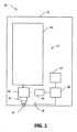
図1は、分注システム10の例示的実施形態の概略図である。分注システム10はハウジング12を含む。ハウジング12内に位置するのは、例えば、ローション、石鹸または消毒剤などの液体を保持する容器である。容器14と流体連通するのは、ポンプ16である。この例示的な実施形態では、ポンプ16は、空気と液体の両方を送り出す発泡体ポンプであるが、いくつかの実施形態では、ポンプは液体ポンプである。ポンプ16と流体連通するのは、差動ボアサックバックデバイス20および出口22である。いくつかの実施形態では、容器、ポンプ、およびサックバックバックデバイス20は、再充填ユニット17と総称される。こうした実施形態では、再充填ユニット17は、使い果たした時、さもなくば故障した時、ハウジング12から取り外して、流体を充填した新しい再充填ユニットと交換することができる。いくつかの実施形態では、ディスペンサーハウジング12からポンプ16を取り外すことなく、容器14を取り外すことができる。いくつかの実施形態では、容器14はキャップ(図示せず)および弁(図示せず)を有し、容器14をディスペンサー内に取り付け、漏れることなく逆さ位置でそこから取り外すことを可能にする。 FIG. 1 is a schematic diagram of an exemplary embodiment of a
また、ハウジング12に含まれるものは、例えば、マイクロプロセッサなどのプロセッサ28、例えば、複数の電池などの電源22、ポンプ26を作動させるためのアクチュエータ24、および、例えば、ユーザーの手を感知する赤外線センサーなどのセンサー26である。電源22、センサー26およびコントローラ24は、プロセッサ28と回路通信する。さらに、例えば、本明細書に組み込まれる上記の参考文献に記載される回路など、追加的回路が含まれうる。 Also included in the
いくつかの実施形態では、ディスペンサーは手動ディスペンサーである。こうした実施形態では、プロセッサ28、電源22、およびセンサー26を含む電子機器は必要としない場合がある。ポンプ16を駆動するために手動アクチュエータが含まれる。サックバックバックデバイス20はまた、本明細書に記述されるように動作してもよい。 In some embodiments the dispenser is a manual dispenser. In such embodiments,
図2を参照すると、発泡体を分注するためのシステム100の一部分の側面図が示されている。システムは、モーター101、ポンプ部分102、および発泡体発生アセンブリ103を含む。この例示的な実施形態では、発泡体を分注するためのシステム100の部分は、液体入口104および液体入口導管110を含み、これは発泡性液体で充填された貯蔵部または容器(図示せず)に接続される。この例示的なシステム100は、一方向入口弁126、混合チャンバー106、流体出口導管107、差動ボアハウジング108、底部トレー109、および発泡体出口111を保持するためのチャンバー105を含む。例示的な実施形態では、モーターおよびダイアフラムは、参照により本明細書に組み込まれる、例えば、ピストンポンプ、手動アクチュエータ、電子アクチュエータ、および同種のものなど、他のタイプのポンプおよび/またはアクチュエータによって置き換えられてもよい。例示的な実施形態では、モーターおよびポンプダイアフラムアセンブリは、例えば、2016年11月14日に出願され、「Foaming Cartridge」と題された米国特許出願番号第15/350,190号、および2016年11月18日出願され、「Sequentially Activated Multi-Diaphragm Foam Pumps, Refill Units and Dispenser Systems」と題された米国特許出願番号第15/355,112号に開示されているものとすることができ、これらすべてはその全体が参照により本明細書に組み込まれる。 Referring to FIG. 2, a side view of a portion of
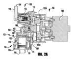
図2Aおよび図2Bは、サックバックデバイス123を有するシステム100の(一部分の)断面図である。図4は、サックバックデバイス123の拡大断面図である。例示的なシステム100は、液体入口開口部104、液体入口通路110、一方向液体入口弁126を含み、これは、例えば、示すように、ボール112およびばね113を有するボール弁アセンブリとしうる。開示された実施形態では、その他のタイプの一方向入口弁が使用されうる。いくつかの実施形態では、一方向液体入口弁は、マッシュルーム弁、アンブレラ弁、フラッパー弁、スリット弁、ダックビル弁、マッシュボール弁等であってもよい。例示的なシステム100は、ポンプ部分102およびモーター101を含む。ポンプ部分102は四つのポンピングダイアフラムを含む。ポンピングダイアフラム121A、121Bをこの図に示す。ポンプダイアフラム121Aは、液体ポンプダイアフラムである。ポンプダイアフラム121Bおよび二つの追加のポンプダイアフラム(図示せず)は、空気ポンプダイアフラムである。 2A and 2B are (partial) cross-sectional views of
この例示的な実施形態は、四つのポンプダイアフラムを開示しているが、より少ないまたはより多いポンプダイアフラムを有するポンプを使用してもよい。いくつかの実施形態では、一つまたは複数のポンプダイアフラムは、液体ポンプダイアフラムであり、いくつかの実施形態では、一つまたは複数のダイアフラムは、空気ポンプダイアフラムである。ダイアフラムアセンブリの例示的な詳細および構成要素は、例えば、米国特許出願番号第15/350,190号および第15/355,112号の出願を含む、本明細書に組み込まれる任意の出願から参照によりその全体が本明細書に組み込まれる。この例示的なシステム100は、一方向流体出口弁109、混合チャンバー106、流体通路107、および差動ボアハウジング108をさらに含む。 Although this exemplary embodiment discloses four pump diaphragms, pumps with fewer or more pump diaphragms may be used. In some embodiments, the one or more pump diaphragms are liquid pump diaphragms, and in some embodiments the one or more diaphragms are air pump diaphragms. Exemplary details and components of the diaphragm assembly can be found by reference from any application incorporated herein, including, for example, U.S. Patent Application Serial Nos. 15/350,190 and 15/355,112. is incorporated herein in its entirety. This
差動ボアハウジング108は、差動ボアハウジング108の大きいボア124に空気の出入りを可能にする開口部122を含む。差動ボアハウジング108は、小さいボア123および大きいボア124を有する。開口部122は、大きいボア124の上部に空気が出入りすることを可能にし、空気ロックがデュアルピストンボディ114の移動を阻害するのを防止する。差動ボアハウジング108内に位置するのは、デュアルピストンボディ114である。 Differential bore
デュアルピストンボディ114は、小さいピストン115、大きいピストン116、および流量制限器131を有する。流量制限器131は、弁、小さい穴、バッフル、スクリーン、スポンジまたはこれに類するものであってもよい。流量制限器131は、流体空気混合物からの圧力がデュアルピストンボディ114を下に移動させるようにサイズ決めおよび構成される。例えば、ばねなどの付勢部材135は、デュアルピストンボディ114を上に付勢する。
例えば、流量制限器131は、付勢部材135を移動する力よりも大きいクラッキング圧力を有する弁であってもよい。適切な弁は、スリット弁、ダックビル弁、フラッパー弁、アンブレラ弁などであってもよい。いくつかの実施形態では、流体が通り抜けるときに十分な力が液体空気混合物によって生成されることを可能にするサイズの開口部が、流量制限器131として使用されてもよい。いくつかの実施形態では、開口部およびスクリーンを、流量制限器131として使用して、デュアルピストンボディ114を移動させるのに十分な圧力を作り出すことができる。いくつかの実施形態では、開口部および発泡部材を、発泡チャンバー内の流量制限器131として使用して、デュアルピストンボディ114を移動させるのに十分な力を作り出すことができる。発泡体を作るためのシステム100は、底部プレート109を通って位置する発泡体出口通路111も有する。底部プレート109は、底部プレート109の表面119の上方に延在する発泡体出口通路111の周りのリップ118と、発泡体出口136とを含む。以下でより詳細に説明するように、リップ118は、サックバックチャンバー150内に残留液体を保持する。 For example, flow
動作中に発泡体の分注が呼び出されると、液体は、液体入口104から入口導管110を通って、一方向入口弁126を通過し、液体ポンプダイアフラム121Aに入り、流体出口弁105を通過し、混合チャンバー106内に引き込まれる。空気は、一つまたは複数の空気入口(図示せず)を通して空気ポンプダイアフラム121B(およびこの例示的実施形態では図示されていない、二つの追加的な空気ポンプダイアフラム)内に流れ込む。空気は、空気ポンプダイアフラムから、流体出口弁105を通って、混合チャンバー106内に流れ、液体空気が混合して液体/空気混合物を形成する。液体/空気混合物は、流量制限器131を通って流れ、それによってデュアルピストンボディ114が下方に移動し、デュアルピストンボディ114を通って、第一の混合媒体133を通過し、第一の発泡体ステージ領域128に入り、第二の混合媒体134を通って、出口ノズル111の開口部136から出る。第一の混合媒体133および第二の混合媒体134は、この例示的な実施形態において、スクリーンであるが、混合媒体は、例えば、複数のバッフル、一つまたは複数の多孔性部材、一つまたは複数のスポンジなどであってもよい。 When foam dispensing is invoked during operation, liquid flows from
液体/空気混合物が流量制限器131を通って流れると、小さいピストン115および大きいピストン116を含むデュアルピストンボディ114が、付勢部材135を強制的に下方に圧縮し、サックバックバックチャンバー145の容積を圧縮する。サックバックチャンバー145の容積が圧縮されると、サックバックチャンバー145内の残留発泡体および液体は強制的に排出され、出口ノズル111を通して分注される。 As the liquid/air mixture flows through
発泡体の流れが停止すると、付勢部材135は、デュアルピストンボディ114、小さいピストン115、および大きいピストン116を上方に動かし、サックバックチャンバー145を拡張させる。小さいピストン115の上方への移動により、上部チャンバー内の液体/空気混合物の一部が、制限器131および混合媒体133、134を通って流れる。出口ノズル111および第一の発泡ステージ128内の残留発泡体は、サックバックチャンバー145に吸い込まれる。 When the foam flow stops, biasing
リップ118は、サックバックチャンバー145の底面148の上に延びる。したがって、サックバックチャンバー145に入る残留発泡体が壊れ、液体になると、デュアルピストンボディ114が再び下方に移動し、サックバックチャンバー145から残留発泡体/液体が排出されるまで、液体はリップ118によってサックバックチャンバー145内に保持される。
図3は、上述の発泡体作製アセンブリ103の構成要素の分解図を示す。この例示的な実施形態では、流量制限器131はスリット弁として図示されている。 FIG. 3 shows an exploded view of the components of the
図4は、差動ボア402を含むハウジング108の拡大図である。差動ボア402は、第一の直径を有する第一の部分および第二の直径を有する第二の部分を含む。第二の直径は第一の直径よりも大きい。差動ボア402内に位置するのは、デュアルピストンボディ114および発泡体カートリッジ128である。底部トレー129は、ハウジング108に接続され、出口ノズル111、液体保持部材118、および発泡体出口136を含む。 FIG. 4 is an enlarged view of
図5は、デュアルピストンボディ114の拡大図であり、図6は底部トレー109の拡大図である。 5 is an enlarged view of the
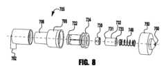
図7は、差動ボア705、デュアルピストンボディ720、および発泡体出口760を有するサックバックデバイス700の別の例示的な実施形態の断面図である。デュアルピストンボディ720は、デュアルボア705の小さいボア706内で往復する第一の小さいピストン722と、大きいボア708内で往復する大きいピストン724とを有する。サックバックデバイス700は、液体空気発泡体混合物を受けるための入口702を有する。 FIG. 7 is a cross-sectional view of another exemplary embodiment of a
いくつかの実施形態では、差動ボアハウジング705は、差動ボアハウジング705の大きいボア709に空気の出入りを可能にする開口部708を含む。開口部709は、大きいボア708の上部に空気が出入りすることを可能にし、空気ロックがデュアルピストンボディ720の移動を阻害するのを防止する。 In some embodiments,
さらに、デュアルピストンボディ720は、流量制限器730を含む。流量制限器730は、弁、小さい穴、バッフル、スクリーン、スポンジまたはこれに類するものであってもよい。流量制限器730は、流体空気混合物からの圧力がデュアルピストンボディ720を下に移動させるようにサイズ決めおよび構成される。例えば、ばねなどの付勢部材748は、デュアルピストンボディ720を上に付勢する。 Additionally,
流量制限器730は、付勢部材1748を移動する力よりも大きいクラッキング圧力を有する弁であってもよい。適切な弁は、スリット弁、ダックビル弁、フラッパー弁、アンブレラ弁などであってもよい。いくつかの実施形態では、流量制限器730は、十分な力が液体空気混合物によって生成されることを可能にするサイズの開口部であり、流量制限器730として使用されてもよい。いくつかの実施形態では、開口部および一つまたは複数のスクリーンを、流量制限器730として使用して、デュアルピストンボディ720を移動させるのに十分な圧力を作り出すことができる。いくつかの実施形態では、開口部および多孔性部材を、発泡チャンバー内の流量制限器730として使用して、デュアルピストンボディ720を移動させるのに十分な力を作り出すことができる。サックバックデバイス700はまた、底部プレート750を通って位置する発泡体出口通路760を有する。底部プレート750は、底部表面752と、底部プレート750の底部表面752の上方に延在する発泡体出口760の周りのリップ754と、発泡体出口760とを含む。以下でより詳細に説明するように、リップ754は、サックバックチャンバー780内に残留液体を保持する。 Flow restrictor 730 may be a valve that has a cracking pressure greater than the force that moves biasing member 1748 . Suitable valves may be slit valves, duckbill valves, flapper valves, umbrella valves, and the like. In some embodiments,
動作中に発泡体の分注が呼び出されると、液体/空気混合物は、入口702を通って、流量制限器730を通り、それによってデュアルピストンボディ720を下方に移動させ、デュアルピストンボディ720の内部を通り、第一の混合媒体731を通過して、第一の発泡ステージ領域732に入り、第二の混合媒体733を通って、発泡体出口760から出る。第一の混合媒体731および第二の混合媒体732は、この例示的な実施形態において、スクリーンであるが、一つまたは複数の混合媒体は、例えば、複数のバッフル、一つまたは複数の多孔性部材、一つまたは複数のスポンジなどであってもよい。いくつかの実施形態では、混合媒体は必要ない。 When foam dispensing is invoked during operation, the liquid/air mixture flows through
液体/空気混合物が流量制限器730を通って流れると、小さいピストン722および大きいピストン724を含むデュアルピストンボディ720が、付勢部材748を強制的に下方に圧縮し、サックバックバックチャンバー780の容積を圧縮する。サックバックチャンバー780の容積が圧縮されると、サックバックチャンバー780内の残留発泡体および液体は吹き出され、出口ノズル760を通して分注される。 As the liquid/air mixture flows through the
発泡体出力が停止すると、付勢部材748は、小さいピストン722および大きいピストン724を含む、デュアルピストンボディ750を上方に動かし、サックバックチャンバー780を拡張させる。小さいピストン722の上方への移動により、上部チャンバー内の液体/空気混合物が、制限器および混合媒体731、733を通って流れる。出口760および第一の発泡ステージ732内の残留発泡体は、サックバックチャンバー780に吸い込まれる。 When foam output stops, biasing
リップ754は、サックバックチャンバー780の底面752の上に延びる。したがって、サックバックチャンバー780に入る残留発泡体が壊れ、液体になると、デュアルピストンボディ720が再び下方に移動し、サックバックチャンバー780から残留発泡体/液体が排出されるまで、液体はリップ754によってサックバックチャンバー780内に保持される。
図8は、図7のサックバックデバイスの分解透視図である。 8 is an exploded perspective view of the suckback device of FIG. 7; FIG.
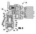
図9は、差動ボア905、デュアルピストンボディ920、および発泡体出口960を有するサックバックデバイス900の別の例示的な実施形態の断面図である。サックバックデバイス900は、ポンプ102の出口に接続される。ポンプ102は、連続的に起動されたダイアフラム発泡体ポンプであるが、参照により本明細書に記載および/または組み込まれるものなど、任意のタイプのポンプであってもよい。デュアルピストンボディ920は、デュアルボア905の小さいボア906内で往復する第一の小さいピストン922と、大きいボア908内で往復する大きいピストン924とを有する。サックバックデバイス900は、液体空気発泡体混合物を受けるための入口902を有する。 FIG. 9 is a cross-sectional view of another exemplary embodiment of a
いくつかの実施形態では、差動ボアハウジング905は、差動ボアハウジング905の大きいボア909に空気の出入りを可能にする開口部908を含む。開口部908は、大きいボア908の上部に空気が出入りすることを可能にし、空気ロックがデュアルピストンボディ920の移動を阻害するのを防止する。 In some embodiments,
さらに、デュアルピストンボディ920は、流量制限器930を含む。この例示的な実施形態では、流量制限器930はダックビル弁である。その他のタイプの弁を使用してもよい。いくつかの実施形態では、流量制限器は、弁、小さい穴、バッフル、スクリーン、スポンジまたはこれに類するものであってもよい。流量制限器930は、流体空気混合物からの圧力がデュアルピストンボディ920を下に移動させるようにサイズ決めおよび構成される。例えば、ばねなどの付勢部材948は、デュアルピストンボディ920を上に付勢する。好ましくは、流量制限器930は、付勢部材948を移動する力よりも大きいクラッキング圧力を有する。その他の適切な弁は、スリット弁、フラッパー弁、アンブレラ弁などであってもよい。 Additionally,
サックバックデバイス900はまた、底部プレート950を通って位置する発泡体出口通路960を有する。底部プレート950は、底部表面952と、底部プレート950の底部表面952の上方に延在する発泡体出口960の周りのリップ954と、発泡体出口960とを含む。以下でより詳細に説明するように、リップ954は、サックバックチャンバー980内に残留液体を保持する。さらに、付勢部材948は大きいボア908に位置し、床952上に置かれる。デュアルピストンボディ920の環状溝946は、付勢部材948の上端を保持する。 The
動作中に発泡体の分注が呼び出されると、液体/空気混合物は、入口902を通って、流量制限器930を通り、それによってデュアルピストンボディ920を下方に移動させ、デュアルピストンボディ920の内部を通り、第一の混合媒体931を通過して、第一の発泡ステージ領域932に入り、第二の混合媒体933を通って、発泡体出口960から出る。第一の混合媒体931および第二の混合媒体932は、この例示的な実施形態において、スクリーンであるが、混合媒体は、例えば、複数のバッフル、一つまたは複数の多孔性部材、一つまたは複数のスポンジなどであってもよい。いくつかの実施形態では、混合媒体は必要ない。 When foam dispensing is invoked during operation, the liquid/air mixture flows through
液体/空気混合物が流量制限器930を通って流れると、小さいピストン922および大きいピストン924を含むデュアルピストンボディ920が、付勢部材948を強制的に下方に圧縮し、サックバックバックチャンバー980の容積を圧縮する。サックバックチャンバー980の容積が圧縮されると、サックバックチャンバー980内の残留発泡体および液体は吹き出され、出口ノズル960を通して分注される。 As the liquid/air mixture flows through the
流体混合物がサックバックデバイス900への流れを停止すると、付勢部材948は、小さいピストン922および大きいピストン924を含む、デュアルピストンボディ950を上方に動かし、サックバックチャンバー980を拡張させる。小さいピストン922の上方への移動により、上部チャンバー内の液体/空気混合物が、制限器および混合媒体931、933を通って流れる。出口960および第一の発泡ステージ932内の残留発泡体は、サックバックチャンバー980に吸い込まれる。 When the fluid mixture stops flowing into
リップ954は、サックバックチャンバー980の底面952の上に延びる。本明細書に開示されるサックバックデバイスのいくつかの実施形態では、リップは必要ない。例えば、この例示的実施形態では、底面952またはその一部分は、出口960から傾斜して、流体をサックバックバックデバイス900内に保持することができる。したがって、サックバックチャンバー980に入る残留発泡体が壊れ、液体になると、デュアルピストンボディ920が再び下方に移動し、サックバックチャンバー980から残留発泡体/液体が排出されるまで、液体はリップ954(または、例えば、傾斜床などの他の手段)によってサックバックチャンバー980内に保持される。
図10は、差動ボア1005、デュアルピストンボディ1020、および発泡体出口1060を有するサックバックデバイス1000の別の例示的な実施形態の断面図である。サックバックデバイス1000は、ポンプ102の出口に接続される。ポンプ102は、連続的に起動されたダイアフラム発泡体ポンプであるが、参照により本明細書に記載および/または組み込まれるものなど、任意のタイプのポンプであってもよい。サックバックデバイス1000は、液体空気発泡体混合物を受けるための入口1002を有する。デュアルピストンボディ1020は、デュアルボア1005の小さいボア1006内で往復する第一の小さいピストン1022と、大きいボア1008内で往復する大きいピストン1024とを有する。 FIG. 10 is a cross-sectional view of another exemplary embodiment of a
いくつかの実施形態では、差動ボアハウジング1005は、差動ボアハウジング1005の大きいボア1009に空気の出入りを可能にする開口部1008を含む。開口部1008は、大きいボア1008の上部に空気が出入りすることを可能にし、空気ロックがデュアルピストンボディ1020の移動を阻害するのを防止する。 In some embodiments,
さらに、デュアルピストンボディ1020は、流量制限器1030を含む。この例示的実施形態では、流量制限器1030は、小さいボア1006に沿って移動し、より小さいピストン1022と反対方向を向くワイパーシール1023である。さらに、デュアルピストンボディ1020は、デュアルピストンボディ1020を通ってデュアルピストンボディ1020の内部に入る通路1080、1081を含む。 Additionally,
いくつかの実施形態では、流量制限器1030は、少なくとも部分的に、ピストンボディの上面1090、および入口1002を囲むハウジングの底面1091によって形成される。いくつかの実施形態では、表面1090は、付勢部材1048がデュアルピストンボディ1020をその最上位置に付勢すると、表面1091とシールを形成する。 In some embodiments, the
例えば、ばねなどの付勢部材1048は、デュアルピストンボディ1020を上に付勢する。好ましくは、流量制限器1030は、付勢部材1048を移動する力よりも大きいクラッキング圧力を有する。 A biasing
サックバックデバイス1000はまた、底部プレート1050を通って位置する発泡体出口通路1060を有する。底部プレート1050は、底部表面1052と、底部プレート1050の底部表面1052の上方に延在する発泡体出口1060の周りの任意のリップ1054と、発泡体出口1060とを含む。以下でより詳細に説明するように、リップ1054は、サックバックチャンバー1080内に残留液体を保持する。さらに、付勢部材1048は大きいボア1008に位置し、床1052上に置かれる。デュアルピストンボディ1020の環状溝1046は、付勢部材1048の上端を保持する。 The
動作中に発泡体の分注が呼び出されると、液体/空気混合物は、入口1002を通って、流量制限器1030の周りを流れ、それによってデュアルピストンボディ1020を下方に移動させ、通路1080、1081を通って、デュアルピストンボディ1020の内部を通り、第一の混合媒体1031を通過して、第一の発泡ステージ領域1032に入り、第二の混合媒体1033を通って、発泡体出口1060から出る。第一の混合媒体1031および第二の混合媒体1032は、この例示的な実施形態において、スクリーンであるが、混合媒体は、例えば、複数のバッフル、一つまたは複数の多孔性部材、一つまたは複数のスポンジなどであってもよい。いくつかの実施形態では、混合媒体は必要ない。 When foam dispensing is invoked during operation, the liquid/air mixture flows through the
液体/空気混合物が流量制限器1030の周りを流れると、小さいピストン1022および大きいピストン1024を含むデュアルピストンボディ1020が、付勢部材1048を強制的に下方に圧縮し、サックバックバックチャンバー1080の容積を圧縮する。サックバックチャンバー1080の容積が圧縮されると、サックバックチャンバー1080内の残留発泡体および液体は吹き出され、出口ノズル1060を通して分注される。 As the liquid/air mixture flows around
流体混合物がサックバックデバイス1000への流れを停止すると、付勢部材1048は、小さいピストン1022および大きいピストン1024を含む、デュアルピストンボディ1050を上方に動かし、サックバックチャンバー1080を拡張させる。小さいピストン1022の上方への移動により、上部チャンバー内の液体/空気混合物が、制限器および混合媒体1031、1033を通って流れる。出口1060および第一の発泡ステージ1032内の残留発泡体は、サックバックチャンバー1080に吸い込まれる。 When the fluid mixture stops flowing into
リップ1054は、サックバックチャンバー1080の底面1052の上に延びる。本明細書に開示されるサックバックデバイスのいくつかの実施形態では、リップは必要ない。例えば、この例示的実施形態では、底面1052またはその一部分は、出口1060から傾斜して、流体をサックバックバックデバイス1000内に保持することができる。したがって、サックバックチャンバー1080に入る残留発泡体が壊れ、液体になると、デュアルピストンボディ1020が再び下方に移動し、サックバックチャンバー1080から残留発泡体/液体が排出されるまで、液体はリップ1054(または、例えば、傾斜床などの他の手段)によってサックバックチャンバー1080内に保持される。
本明細書に開示される本発明の概念は、本明細書に記載される特定の実施形態による範囲に限定されるものではない。さらに、いくつかの実施形態は、特定の目的のために、特定の環境で、特定の実施に関連して本明細書に説明されているが、当業者は、その有用性がそれに限定されず、さまざまな実施形態が、任意の数の目的のために、任意の数の環境で、有益に実施されうることを認識するべきである。したがって、以下に記載される特許請求の範囲は、本明細書に開示される実施形態の全容および趣旨の観点から解釈されるべきである。前述の説明には多くの詳細および特異性が含まれるが、これらは説明の目的のためにのみ含まれており、さまざまな実施形態の制限として解釈されるべきではないことを理解されたい。上述の実施形態に対する多くの修正は、本説明の趣旨および範囲から逸脱することなく行うことができる。 The inventive concepts disclosed herein are not to be limited in scope by the specific embodiments described herein. Moreover, although some embodiments have been described herein in connection with particular implementations, in particular environments, for particular purposes, those skilled in the art will appreciate that their usefulness is not so limited. , it should be recognized that the various embodiments may be beneficially implemented for any number of purposes and in any number of environments. Therefore, the claims set forth below should be interpreted in light of the full scope and spirit of the embodiments disclosed herein. It should be understood that while the foregoing description contains many details and specificities, these are included for purposes of illustration only and should not be construed as limitations on the various embodiments. Many modifications to the above-described embodiments can be made without departing from the spirit and scope of this description.
Claims (20)
Translated fromJapanese発泡性液体を保持する容器と、
前記発泡性液体を空気で混合して発泡体混合物を形成するポンプと、
サックバックデバイスと、
前記サックバックデバイスと流体連通するように前記ポンプの出口を設置する流体出口導管と、を備え、
前記サックバックデバイスは、
前記流体出口導管から液体を受け取る液体入口を有し、
第一の直径を有する小さいボアを有する上流部分と、第二の直径を有する大きいボアを有する下流部分とを有し、
前記第一の直径は前記第二の直径よりも小さい、ハウジングと、
前記小さいボア内で往復する第一のピストンと、前記大きいボア内で往復する第二のピストンとを有する、デュアルボディピストンと、
上流位置での前記デュアルボディピストンを付勢する付勢部材と、
前記デュアルボディピストンに近接して位置する流量制限器と、
前記大きいボアおよび前記第二のピストンによって少なくとも部分的に形成されたサックバックチャンバーと、
発泡体出口と、を備え、
前記流量制限器は、前記サックバックデバイスへの流体流が前記サックバックチャンバーを圧縮させ、前記流体流が停止すると、前記付勢部材が前記サックバックチャンバーを拡張させ、残留発泡体を前記サックバックチャンバーに吸い戻すように構成される、発泡体を分注するためのシステム。A system for dispensing foam, comprising:
a container holding an effervescent liquid;
a pump for mixing the foamable liquid with air to form a foam mixture;
a suckback device;
a fluid outlet conduit placing the outlet of the pump in fluid communication with the suckback device;
The suckback device is
having a liquid inlet for receiving liquid from the fluid outlet conduit;
having an upstream portion with a small bore having a first diameter and a downstream portion having a large bore with a second diameter;
a housing, wherein the first diameter is smaller than the second diameter;
a dual-body piston having a first piston that reciprocates within the small bore and a second piston that reciprocates within the large bore;
a biasing member for biasing the dual-body piston in an upstream position;
a flow restrictor located proximate to the dual-body piston;
a suckback chamber at least partially defined by said large bore and said second piston;
a foam outlet;
The flow restrictor is configured such that fluid flow to the suckback device compresses the suckback chamber, and when the fluid flow stops, the biasing member expands the suckback chamber, pushing residual foam into the suckback. A system for dispensing foam configured to draw back into the chamber.
ポンプから液体を受け取る液体入口を有し、
第一の直径を有する第一のボアおよび第二の直径を有する第二のボアを有し、
前記第一の直径が前記第二の直径よりも小さい、ハウジングと、
前記第一のボアの壁と接触するようにサイズ決めされた第一のピストンシールと、前記第二のボアの壁と接触するようにサイズ決めされた第二のピストンシールであって、
前記第一のピストンシールが、流量制限器を含むボディに接続され、
ピストンは、付勢部材によって上方に付勢される、第一および第二のピストンシールと、
前記第二のピストンシールの上端の上側の前記大きいボアの上部に空気が出入りすることを可能にする、前記ハウジングへの開口部と、
前記第二のボアおよび前記第二のピストンによって少なくとも部分的に形成されたサックバックチャンバーと、
前記第二のボアに近接する前記ハウジング内に位置する出口と、
発泡体が前記サックバックチャンバーから流れ出ることを可能にするための発泡体出口と、を備え、
前記流量制限器を通る流体流が、前記第一のピストンシールおよび前記第二のピストンシールを第一の方向に動かし、前記サックバックチャンバーを圧縮させ、
前記付勢部材が、前記第一のピストンシールおよび前記第二のピストンシールを第二の方向に動かし、前記サックバックチャンバーを拡張させる、差動ボアサックバックデバイス。A differential bore suckback device,
having a liquid inlet for receiving liquid from the pump;
having a first bore having a first diameter and a second bore having a second diameter;
a housing, wherein the first diameter is smaller than the second diameter;
a first piston seal sized to contact the wall of the first bore and a second piston seal sized to contact the wall of the second bore,
said first piston seal is connected to a body containing a flow restrictor;
the piston includes first and second piston seals biased upwardly by a biasing member;
an opening in the housing that allows air to enter and exit the upper portion of the large bore above the upper end of the second piston seal;
a suckback chamber at least partially defined by said second bore and said second piston;
an outlet located within the housing proximate the second bore;
a foam outlet for allowing foam to flow out of the suckback chamber;
fluid flow through the flow restrictor moves the first piston seal and the second piston seal in a first direction to compress the suckback chamber;
The differential bore suckback device, wherein the biasing member moves the first piston seal and the second piston seal in a second direction to expand the suckback chamber.
ポンプから液体を受け取る液体入口を有し、
第一の直径を有する第一のボアおよび第二の直径を有する第二のボアを有し、
前記第一の直径が前記第二の直径よりも小さい、ハウジングと、
前記第一のボアの壁と接触するようにサイズ決めされた第一のピストンシールと、前記第二のボアの壁と接触するようにサイズ決めされた第二のピストンシールであって、
前記第一のピストンシールが、流量制限器を含むボディに接続され、
ピストンは、付勢部材によって上方に付勢される、第一および第二のピストンシールと、
前記第二のボアおよび前記第二のピストンによって少なくとも部分的に形成されたサックバックチャンバーと、
前記第二のピストンシールの上端の上側の前記大きいボアの上部に空気が出入りすることを可能にする、前記ハウジングへの開口部と、
前記第二のボアに近接する前記ハウジング内に位置する出口と、
液体が前記サックバックチャンバーから流れ出ることを可能にするための液体出口と、を備え、
前記流量制限器を通る液体流が、前記第一のピストンシールおよび前記第二のピストンシールを第一の方向に動かし、前記サックバックチャンバーを圧縮させ、
前記付勢部材が、前記第一のピストンシールおよび前記第二のピストンシールを第二の方向に動かし、前記サックバックチャンバーを拡張させる、差動ボアサックバックデバイス。A differential bore suckback device,
having a liquid inlet for receiving liquid from the pump;
having a first bore having a first diameter and a second bore having a second diameter;
a housing, wherein the first diameter is smaller than the second diameter;
a first piston seal sized to contact the wall of the first bore and a second piston seal sized to contact the wall of the second bore,
said first piston seal is connected to a body containing a flow restrictor;
the piston includes first and second piston seals biased upwardly by a biasing member;
a suckback chamber at least partially defined by said second bore and said second piston;
an opening in the housing that allows air to enter and exit the upper portion of the large bore above the upper end of the second piston seal;
an outlet located within the housing proximate the second bore;
a liquid outlet for allowing liquid to flow out of the suckback chamber;
liquid flow through the flow restrictor moves the first piston seal and the second piston seal in a first direction to compress the suckback chamber;
The differential bore suckback device, wherein the biasing member moves the first piston seal and the second piston seal in a second direction to expand the suckback chamber.
Applications Claiming Priority (3)
| Application Number | Priority Date | Filing Date | Title |
|---|---|---|---|
| US201862649069P | 2018-03-28 | 2018-03-28 | |
| US62/649,069 | 2018-03-28 | ||
| PCT/US2019/024022WO2019191060A1 (en) | 2018-03-28 | 2019-03-26 | Foam pumps, refill units and dispensers with differential bore suck-back mechanism |
Publications (2)
| Publication Number | Publication Date |
|---|---|
| JP2021519679A JP2021519679A (en) | 2021-08-12 |
| JP7299912B2true JP7299912B2 (en) | 2023-06-28 |
Family
ID=66092403
Family Applications (1)
| Application Number | Title | Priority Date | Filing Date |
|---|---|---|---|
| JP2020552228AActiveJP7299912B2 (en) | 2018-03-28 | 2019-03-26 | Foam pump, refill unit, and dispenser with differential bore sackback mechanism |
Country Status (6)
| Country | Link |
|---|---|
| US (1) | US10786121B2 (en) |
| EP (1) | EP3773100B1 (en) |
| JP (1) | JP7299912B2 (en) |
| AU (1) | AU2019243017B2 (en) |
| CA (1) | CA3094987A1 (en) |
| WO (1) | WO2019191060A1 (en) |
Families Citing this family (2)
| Publication number | Priority date | Publication date | Assignee | Title |
|---|---|---|---|---|
| US10441115B2 (en) | 2016-02-11 | 2019-10-15 | Gojo Industries, Inc. | High quality non-aerosol hand sanitizing foam |
| US10912426B2 (en) | 2016-04-06 | 2021-02-09 | Gojo Industries, Inc. | Sequentially activated multi-diaphragm foam pumps, refill units and dispenser systems |
Citations (6)
| Publication number | Priority date | Publication date | Assignee | Title |
|---|---|---|---|---|
| JP2002501423A (en) | 1998-03-30 | 2002-01-15 | デブ アイピー リミテッド | Improved foam dispensing liquid dispenser |
| JP2009184735A (en) | 2008-02-08 | 2009-08-20 | Gojo Ind Inc | Foam pump with branched stem |
| JP2009292539A (en) | 2008-05-29 | 2009-12-17 | Gojo Ind Inc | Pull actuated foam pump |
| JP2010540355A (en) | 2007-09-21 | 2010-12-24 | パッケージング イノベーション リミテッド | Discharge mechanism |
| JP2011514470A (en) | 2008-02-08 | 2011-05-06 | ゴジョ・インダストリーズ・インコーポレイテッド | Foam pump with branched stem |
| JP2017520283A (en) | 2014-04-16 | 2017-07-27 | ゴジョ・インダストリーズ・インコーポレイテッド | Mini pump with compressible air inlet chamber to supply residual suckback |
Family Cites Families (23)
| Publication number | Priority date | Publication date | Assignee | Title |
|---|---|---|---|---|
| US5445288A (en)* | 1994-04-05 | 1995-08-29 | Sprintvest Corporation Nv | Liquid dispenser for dispensing foam |
| US8544698B2 (en) | 2007-03-26 | 2013-10-01 | Gojo Industries, Inc. | Foam soap dispenser with stationary dispensing tube |
| CA2875087C (en) | 2007-12-07 | 2016-06-07 | Op-Hygiene Ip Gmbh | Angled slot foam dispenser |
| US8091738B2 (en) | 2008-12-16 | 2012-01-10 | Gojo Industries, Inc. | Manual skin-care product dispenser |
| US8387834B2 (en) | 2009-09-10 | 2013-03-05 | Gojo Industries, Inc. | Dispenser with collapsible dispensing tube |
| US20120248149A1 (en) | 2011-03-30 | 2012-10-04 | Gojo Industries, Inc. | Liquid dispenser |
| US20120285992A1 (en)* | 2011-05-10 | 2012-11-15 | Gojo Industries, Inc. | Foam pump |
| CN102817819B (en)* | 2011-06-10 | 2016-06-08 | 德昌电机(深圳)有限公司 | Micro air pump |
| US8960498B2 (en) | 2011-07-01 | 2015-02-24 | Gojo Industries, Inc. | Touch-free dispenser with single cell operation and battery banking |
| US8485395B2 (en) | 2011-08-02 | 2013-07-16 | Gojo Industries, Inc. | Dispenser lockout mechanism |
| US20130299517A1 (en)* | 2012-05-09 | 2013-11-14 | Gojo Industries, Inc. | Pull-activated foam pumps, dispensers and refill units |
| US20140054323A1 (en) | 2012-08-23 | 2014-02-27 | Gojo Industries, Inc. | Horizontal pumps, refill units and foam dispensers with integral air compressors |
| US9204765B2 (en) | 2012-08-23 | 2015-12-08 | Gojo Industries, Inc. | Off-axis inverted foam dispensers and refill units |
| US9172266B2 (en) | 2013-02-19 | 2015-10-27 | Gojo Industries, Inc. | Power systems for touch free dispensers and refill units containing a power source |
| US9307871B2 (en) | 2012-08-30 | 2016-04-12 | Gojo Industries, Inc. | Horizontal pumps, refill units and foam dispensers |
| US20140124540A1 (en) | 2012-11-07 | 2014-05-08 | Gojo Industries, Inc. | Under-counter mount foam dispensing systems with permanent air compressors and refill units for same |
| US8827119B2 (en) | 2013-01-23 | 2014-09-09 | Gojo Industries, Inc. | Pull pumps, refill units and dispensers for pull pumps |
| US20140261799A1 (en) | 2013-03-14 | 2014-09-18 | Gojo Industries, Inc. | Simplified liquid outlet valves, pumps and refill units |
| US20140263462A1 (en)* | 2013-03-14 | 2014-09-18 | Gojo Industries, Inc. | Simplified liquid outlet valves, pumps and refill units |
| WO2015027130A1 (en) | 2013-08-23 | 2015-02-26 | Gojo Industries, Inc. | Dispenser having top loading and unloading refill units |
| WO2015048698A1 (en)* | 2013-09-30 | 2015-04-02 | Gojo Industries, Inc | Dispensers, refill units and pumps having suck-back features |
| US9648992B2 (en)* | 2013-12-19 | 2017-05-16 | Gojo Industries, Inc. | Pumps with vents to vent inverted containers and refill units having non-collapsing containers |
| WO2015179555A1 (en) | 2014-05-20 | 2015-11-26 | Gojo Industries, Inc. | Two-part fluid delivery systems |
- 2019
- 2019-03-26JPJP2020552228Apatent/JP7299912B2/enactiveActive
- 2019-03-26AUAU2019243017Apatent/AU2019243017B2/ennot_activeCeased
- 2019-03-26EPEP19716270.4Apatent/EP3773100B1/enactiveActive
- 2019-03-26USUS16/364,678patent/US10786121B2/enactiveActive
- 2019-03-26WOPCT/US2019/024022patent/WO2019191060A1/ennot_activeCeased
- 2019-03-26CACA3094987Apatent/CA3094987A1/enactivePending
Patent Citations (6)
| Publication number | Priority date | Publication date | Assignee | Title |
|---|---|---|---|---|
| JP2002501423A (en) | 1998-03-30 | 2002-01-15 | デブ アイピー リミテッド | Improved foam dispensing liquid dispenser |
| JP2010540355A (en) | 2007-09-21 | 2010-12-24 | パッケージング イノベーション リミテッド | Discharge mechanism |
| JP2009184735A (en) | 2008-02-08 | 2009-08-20 | Gojo Ind Inc | Foam pump with branched stem |
| JP2011514470A (en) | 2008-02-08 | 2011-05-06 | ゴジョ・インダストリーズ・インコーポレイテッド | Foam pump with branched stem |
| JP2009292539A (en) | 2008-05-29 | 2009-12-17 | Gojo Ind Inc | Pull actuated foam pump |
| JP2017520283A (en) | 2014-04-16 | 2017-07-27 | ゴジョ・インダストリーズ・インコーポレイテッド | Mini pump with compressible air inlet chamber to supply residual suckback |
Also Published As
| Publication number | Publication date |
|---|---|
| US20190298115A1 (en) | 2019-10-03 |
| AU2019243017A1 (en) | 2020-11-19 |
| EP3773100A1 (en) | 2021-02-17 |
| CA3094987A1 (en) | 2019-10-03 |
| EP3773100B1 (en) | 2023-09-20 |
| JP2021519679A (en) | 2021-08-12 |
| US10786121B2 (en) | 2020-09-29 |
| AU2019243017B2 (en) | 2023-07-27 |
| WO2019191060A1 (en) | 2019-10-03 |
Similar Documents
| Publication | Publication Date | Title |
|---|---|---|
| US9433328B2 (en) | Air-activated sequenced valve split foam pump | |
| US8261948B2 (en) | High velocity foam pump | |
| USRE40319E1 (en) | Liquid dispenser for dispensing foam | |
| JP5584129B2 (en) | Device for dispensing fluid | |
| AU2014209540A1 (en) | Pumps with container vents | |
| CN106163356A (en) | There is the foam dispensing pump of compressible air inlet for providing remaining resorption | |
| WO2013036584A1 (en) | Wiper foam pump, refill unit & dispenser for same | |
| US20130299517A1 (en) | Pull-activated foam pumps, dispensers and refill units | |
| JP7299912B2 (en) | Foam pump, refill unit, and dispenser with differential bore sackback mechanism | |
| US10694899B2 (en) | Foam-at-a-distance dispensing systems | |
| JP6869945B2 (en) | Foam cartridge, refill unit, foam dispenser, and foam dispenser system |
Legal Events
| Date | Code | Title | Description |
|---|---|---|---|
| A621 | Written request for application examination | Free format text:JAPANESE INTERMEDIATE CODE: A621 Effective date:20211112 | |
| A131 | Notification of reasons for refusal | Free format text:JAPANESE INTERMEDIATE CODE: A131 Effective date:20221216 | |
| A521 | Request for written amendment filed | Free format text:JAPANESE INTERMEDIATE CODE: A523 Effective date:20230313 | |
| TRDD | Decision of grant or rejection written | ||
| A01 | Written decision to grant a patent or to grant a registration (utility model) | Free format text:JAPANESE INTERMEDIATE CODE: A01 Effective date:20230609 | |
| A61 | First payment of annual fees (during grant procedure) | Free format text:JAPANESE INTERMEDIATE CODE: A61 Effective date:20230616 | |
| R150 | Certificate of patent or registration of utility model | Ref document number:7299912 Country of ref document:JP Free format text:JAPANESE INTERMEDIATE CODE: R150 |