JP7297926B2 - osteotomy guide - Google Patents
osteotomy guideDownload PDFInfo
- Publication number
- JP7297926B2 JP7297926B2JP2021560049AJP2021560049AJP7297926B2JP 7297926 B2JP7297926 B2JP 7297926B2JP 2021560049 AJP2021560049 AJP 2021560049AJP 2021560049 AJP2021560049 AJP 2021560049AJP 7297926 B2JP7297926 B2JP 7297926B2
- Authority
- JP
- Japan
- Prior art keywords
- bone
- guide
- upward
- transverse
- osteotomy guide
- Prior art date
- Legal status (The legal status is an assumption and is not a legal conclusion. Google has not performed a legal analysis and makes no representation as to the accuracy of the status listed.)
- Active
Links
Images


Classifications
- A—HUMAN NECESSITIES
- A61—MEDICAL OR VETERINARY SCIENCE; HYGIENE
- A61B—DIAGNOSIS; SURGERY; IDENTIFICATION
- A61B17/00—Surgical instruments, devices or methods
- A61B17/14—Surgical saws
- A61B17/15—Guides therefor
- A61B17/151—Guides therefor for corrective osteotomy
- A—HUMAN NECESSITIES
- A61—MEDICAL OR VETERINARY SCIENCE; HYGIENE
- A61B—DIAGNOSIS; SURGERY; IDENTIFICATION
- A61B17/00—Surgical instruments, devices or methods
- A61B17/14—Surgical saws
- A61B17/15—Guides therefor
- A61B17/154—Guides therefor for preparing bone for knee prosthesis
- A—HUMAN NECESSITIES
- A61—MEDICAL OR VETERINARY SCIENCE; HYGIENE
- A61B—DIAGNOSIS; SURGERY; IDENTIFICATION
- A61B17/00—Surgical instruments, devices or methods
- A61B17/14—Surgical saws
- A61B17/15—Guides therefor
- A61B17/154—Guides therefor for preparing bone for knee prosthesis
- A61B17/155—Cutting femur
- A—HUMAN NECESSITIES
- A61—MEDICAL OR VETERINARY SCIENCE; HYGIENE
- A61B—DIAGNOSIS; SURGERY; IDENTIFICATION
- A61B17/00—Surgical instruments, devices or methods
- A61B17/14—Surgical saws
- A61B17/15—Guides therefor
- A61B17/154—Guides therefor for preparing bone for knee prosthesis
- A61B17/157—Cutting tibia
- A—HUMAN NECESSITIES
- A61—MEDICAL OR VETERINARY SCIENCE; HYGIENE
- A61B—DIAGNOSIS; SURGERY; IDENTIFICATION
- A61B17/00—Surgical instruments, devices or methods
- A61B17/56—Surgical instruments or methods for treatment of bones or joints; Devices specially adapted therefor
- A61B17/58—Surgical instruments or methods for treatment of bones or joints; Devices specially adapted therefor for osteosynthesis, e.g. bone plates, screws or setting implements
- A61B17/68—Internal fixation devices, including fasteners and spinal fixators, even if a part thereof projects from the skin
- A61B17/80—Cortical plates, i.e. bone plates; Instruments for holding or positioning cortical plates, or for compressing bones attached to cortical plates
- A61B17/8061—Cortical plates, i.e. bone plates; Instruments for holding or positioning cortical plates, or for compressing bones attached to cortical plates specially adapted for particular bones
- A—HUMAN NECESSITIES
- A61—MEDICAL OR VETERINARY SCIENCE; HYGIENE
- A61B—DIAGNOSIS; SURGERY; IDENTIFICATION
- A61B17/00—Surgical instruments, devices or methods
- A61B17/56—Surgical instruments or methods for treatment of bones or joints; Devices specially adapted therefor
- A61B17/58—Surgical instruments or methods for treatment of bones or joints; Devices specially adapted therefor for osteosynthesis, e.g. bone plates, screws or setting implements
- A61B17/68—Internal fixation devices, including fasteners and spinal fixators, even if a part thereof projects from the skin
- A61B17/80—Cortical plates, i.e. bone plates; Instruments for holding or positioning cortical plates, or for compressing bones attached to cortical plates
- A61B17/8095—Wedge osteotomy devices
- A—HUMAN NECESSITIES
- A61—MEDICAL OR VETERINARY SCIENCE; HYGIENE
- A61B—DIAGNOSIS; SURGERY; IDENTIFICATION
- A61B17/00—Surgical instruments, devices or methods
- A61B17/16—Instruments for performing osteoclasis; Drills or chisels for bones; Trepans
- A61B17/17—Guides or aligning means for drills, mills, pins or wires
- A61B17/1739—Guides or aligning means for drills, mills, pins or wires specially adapted for particular parts of the body
- A61B17/1764—Guides or aligning means for drills, mills, pins or wires specially adapted for particular parts of the body for the knee
- A—HUMAN NECESSITIES
- A61—MEDICAL OR VETERINARY SCIENCE; HYGIENE
- A61B—DIAGNOSIS; SURGERY; IDENTIFICATION
- A61B17/00—Surgical instruments, devices or methods
- A61B17/02—Surgical instruments, devices or methods for holding wounds open, e.g. retractors; Tractors
- A61B17/025—Joint distractors
- A61B2017/0268—Joint distractors for the knee
- A—HUMAN NECESSITIES
- A61—MEDICAL OR VETERINARY SCIENCE; HYGIENE
- A61B—DIAGNOSIS; SURGERY; IDENTIFICATION
- A61B17/00—Surgical instruments, devices or methods
- A61B17/56—Surgical instruments or methods for treatment of bones or joints; Devices specially adapted therefor
- A61B2017/568—Surgical instruments or methods for treatment of bones or joints; Devices specially adapted therefor produced with shape and dimensions specific for an individual patient
Landscapes
- Health & Medical Sciences (AREA)
- Surgery (AREA)
- Life Sciences & Earth Sciences (AREA)
- Orthopedic Medicine & Surgery (AREA)
- Medical Informatics (AREA)
- Molecular Biology (AREA)
- Veterinary Medicine (AREA)
- Engineering & Computer Science (AREA)
- Biomedical Technology (AREA)
- Heart & Thoracic Surgery (AREA)
- Public Health (AREA)
- Nuclear Medicine, Radiotherapy & Molecular Imaging (AREA)
- Animal Behavior & Ethology (AREA)
- General Health & Medical Sciences (AREA)
- Dentistry (AREA)
- Oral & Maxillofacial Surgery (AREA)
- Neurology (AREA)
- Physical Education & Sports Medicine (AREA)
- Transplantation (AREA)
- Surgical Instruments (AREA)
Description
Translated fromJapanese本開示は、骨切り術中に骨を切断するための外科用ガイド、及びその使用方法に関する。 The present disclosure relates to a surgical guide for cutting bone during an osteotomy and methods of use thereof.
膝などの関節の軟骨は、経時的に摩耗することがあり得、又は身体活動に関連する損傷に起因して損傷し、変形性関節症をもたらし得る。軟骨の摩耗は、日常生活の活動を制限する疼痛をもたらし得る。典型的には、変形性関節症は、人工関節を埋め込んで元の関節と置き換えることによって治療された。しかしながら、完全な関節置換術にはいくつかの欠点がある。例えば、関節置換術は、多くの場合、金属製又はポリマー製の関節インプラントの取り付けに対応するために、関節の関節面の大部分を除去することを必要とする。更に、置換関節は、最長20年の限られた耐用年数を有することが多く、したがって、多くの場合、後続の置換手術が必要となる。その上更に、関節置換術は、多くの場合、術後感染、骨溶解、及び骨粗しょう症によって悪化し、追加の手術が必要となり得る。 Cartilage in joints such as the knee can wear away over time or can be damaged due to injuries associated with physical activity, resulting in osteoarthritis. Cartilage wear can result in pain that limits activities of daily living. Typically, osteoarthritis was treated by implanting an artificial joint to replace the original joint. However, total joint replacement surgery has several drawbacks. For example, joint replacement surgery often requires removal of a large portion of the joint's articular surface to accommodate the installation of a metallic or polymeric joint implant. Furthermore, replacement joints often have a limited useful life of up to 20 years, thus often requiring subsequent replacement surgery. Furthermore, joint replacement surgery is often complicated by postoperative infection, osteolysis, and osteoporosis, which can require additional surgery.
変形性関節症の早期発症を有する一部の患者は、関節のコンパートメントの全てよりも少ない軟骨摩耗など、関節面の一部のみの軟骨摩耗を経験する。例えば、一部の患者は、関節の2つのコンパートメントのバイコンパートメント変形性関節症、又は関節の1つのコンパートメントのユニコンパートメント変形性関節症を経験し得る。コンパートメント変形性関節症を有する患者では、関節面全体を除去して置換する必要はない場合がある。したがって、高位脛骨骨切り術などの骨切り術は、軟骨が限定的に摩耗した患者において実施され得る。例えば、内側高位脛骨骨切り術は、膝関節を再整列させるために、内側コンパートメント変形性関節症を有する患者に対して行うことができる。 Some patients with early onset osteoarthritis experience cartilage wear on only a portion of the joint surface, such as less than all of the joint's compartment. For example, some patients may experience bicompartmental osteoarthritis of two compartments of a joint, or unicompartmental osteoarthritis of one compartment of a joint. In patients with compartment osteoarthritis, it may not be necessary to remove and replace the entire articular surface. Therefore, osteotomies such as high tibial osteotomies can be performed in patients with limited cartilage wear. For example, a medial high tibial osteotomy can be performed on patients with medial compartment osteoarthritis to realign the knee joint.
内側高位脛骨骨切り術は、脛骨の近位端に隣接する位置において、患者の脛骨の内側に切り込みを形成することによって行われる。患者の脛骨の近位端は、膝の関節面を再整列させるように切り込みを拡大するために枢動される。次いで、脛骨の近位端は、骨プレートを脛骨に取り付けることによって拡大された切り込みを維持するように、定位置に固定されることができる。骨プレートは、拡大された切り込みを横切って延在し、切り込みの両側で脛骨に取り付けられる。いくつかの手順では、プレートが取り付けられる前又は後に、切り込みに骨移植片又は人工骨を充填することができる。 A medial high tibial osteotomy is performed by making an incision on the medial side of the patient's tibia at a location adjacent to the proximal end of the tibia. The proximal end of the patient's tibia is pivoted to enlarge the incision to realign the articular surfaces of the knee. The proximal end of the tibia can then be fixed in place to maintain the enlarged cut by attaching a bone plate to the tibia. A bone plate extends across the enlarged incision and is attached to the tibia on both sides of the incision. In some procedures, the cut can be filled with bone graft or artificial bone before or after the plate is attached.
例示的な実施形態では、骨切りガイドは、骨に面するように構成された内側表面と、外側方向に沿って内側表面と反対側の外側表面とを備える。内側表面及び外側表面のそれぞれは、骨切りガイドの前方端と骨切りガイドの後方端との間に延在する。内側表面は、i)近位骨接触領域、及びii)間隙を画定するように遠位方向に沿って近位骨接触領域から離間している遠位骨接触領域、を画定する。間隙は、近位骨接触領域から遠位骨接触領域まで遠位方向に沿って延在し、かつ内側表面から外側表面に向かって外側方向に沿って延在する。骨切りガイドは、外側表面と内側表面との間に延在する少なくとも1つの上向きガイド面を備える。上向きガイドは、骨内に上向き切り込み経路を少なくとも部分的に画定するように、上向き方向に沿って方向付けられている。上向き方向は、遠位方向、並びに遠位方向及び外側方向のそれぞれに対して垂直である後方方向から角度的にオフセットされている。骨切りガイドは、外側表面と内側表面との間に延在し、かつ、上向き切り込み経路と交差する横断方向切り込み経路を骨内に少なくとも部分的に画定するように、横断方向に沿って方向付けられている。横断ガイド面は、遠位方向に沿って間隙からオフセットされている。 In an exemplary embodiment, the osteotomy guide comprises an inner surface configured to face the bone and an outer surface opposite the inner surface along the lateral direction. Each of the inner and outer surfaces extends between an anterior end of the osteotomy guide and a posterior end of the osteotomy guide. The inner surface defines i) a proximal bone contacting area and ii) a distal bone contacting area spaced apart from the proximal bone contacting area along a distal direction to define a gap. The gap extends along the distal direction from the proximal bone contacting area to the distal bone contacting area and along the lateral direction from the medial surface toward the lateral surface. The osteotomy guide includes at least one upward guide surface extending between an outer surface and an inner surface. The upward guide is oriented along the upward direction to at least partially define an upward cutting path in the bone. The upward direction is angularly offset from the distal direction and the posterior direction, which is perpendicular to each of the distal and lateral directions. The osteotomy guide is oriented along the transverse direction to at least partially define a transverse cutting path in the bone extending between the outer surface and the inner surface and intersecting the upward cutting path. It is The transverse guide surface is offset from the gap along the distal direction.
別の実施形態では、骨切りガイドは、骨切り術の切り込みを骨内にガイドするように構成されている。骨切りガイドは、骨に面するように構成された内側表面と、内側表面と反対側の外側表面とを備える。内側表面の少なくとも一部分は、骨に面するように輪郭付けされている。骨切りガイドは、上向き方向に沿って延在する上向き切り込み経路を間に画定するように互いに向かい合う、第1の上向きガイド面及び第2の上向きガイド面を備える。骨切りガイドは、上向き切り込み経路と交差する横断方向切り込み経路を間に画定するように互いに向かい合う、第1の横断ガイド面及び第2の横断ガイド面を備える。 In another embodiment, the osteotomy guide is configured to guide an osteotomy cut into bone. The osteotomy guide includes an inner surface configured to face the bone and an outer surface opposite the inner surface. At least a portion of the inner surface is contoured to face the bone. The osteotomy guide includes first and second upward guide surfaces facing each other to define an upward cutting path extending along an upward direction therebetween. The osteotomy guide includes first and second transverse guide surfaces facing each other to define therebetween a transverse cutting path that intersects the upward cutting path.
更に別の実施形態では、骨切りガイドは、骨に面するように構成された内側表面と、内側表面と反対側の外側表面とを備える。内側表面及び外側表面のそれぞれは、骨切りガイドの前方端と骨切りガイドの後方端との間に延在する。内側表面は、内側方向に沿って外側表面と反対側である。内側表面は、i)近位骨接触領域と、ii)遠位方向に沿って近位骨接触領域から離間した遠位骨接触領域と、iii)近位骨接触領域と遠位骨接触領域との間に延在する第3の骨接触領域と、を含む。骨切りガイドは、1)近位骨接触領域、遠位骨接触領域、及び第3の骨接触領域によって少なくとも部分的に画定され、かつ、2)内側方向に沿って内側表面から外側表面に向かって延在する、間隙を画定する。骨切りガイドは、外側表面と内側表面との間に延在し、骨内に上向き切り込み経路を少なくとも部分的に画定するように上向き方向に沿って方向付けられている、少なくとも1つの上向きガイド面を備える。上向き方向は、遠位方向、並びに遠位方向及び内側方向のそれぞれに対して垂直である後方方向から角度的にオフセットされている。骨切りガイドは、外側表面と内側表面との間に延在し、上向き切り込み経路方向と交差する横断方向切り込み経路を骨内に少なくとも部分的に画定するように横断方向に沿って方向付けられている。 In yet another embodiment, the osteotomy guide comprises an inner surface configured to face the bone and an outer surface opposite the inner surface. Each of the inner and outer surfaces extends between an anterior end of the osteotomy guide and a posterior end of the osteotomy guide. The inner surface is opposite the outer surface along the inner direction. The inner surface comprises i) a proximal bone contacting area, ii) a distal bone contacting area spaced apart from the proximal bone contacting area along a distal direction, and iii) a proximal bone contacting area and a distal bone contacting area. and a third bone-contacting region extending between. The osteotomy guide is 1) at least partially defined by a proximal bone contacting region, a distal bone contacting region, and a third bone contacting region, and 2) extends along a medial direction from the medial surface to the lateral surface. defines a gap that extends through the The osteotomy guide has at least one upward guide surface extending between the outer surface and the inner surface and oriented along an upward direction to at least partially define an upward cutting path in the bone. Prepare. The upward direction is angularly offset from the distal direction and the posterior direction, which is perpendicular to each of the distal and medial directions. The osteotomy guide extends between the outer surface and the inner surface and is oriented along the transverse direction to at least partially define a transverse cutting path in the bone that intersects the upward cutting path direction. there is
以下の例証的な実施形態の説明は、添付の図面と併せて読むことでより深い理解が得られるであろう。開示されるシステム及び方法の実施形態の可能性は、示されるものに限定されないことを理解されたい。
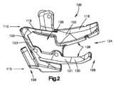
図1~図8を参照すると、一実施形態による骨切りガイド100が示される。骨切りガイド100は、骨切り術処置のために骨に切り込みを形成するために、少なくとも1つの切断器具をガイドするように構成されている。骨切りガイド100は、特定の患者の骨に適合するようにカスタム構築され得る。換言すれば、骨切りガイド100は、患者固有であってもよい。骨切りガイド100は、三次元(3D)プリントされてもよく、又は任意の他の好適な方法で作製されてもよい。少なくともいくつかの実施形態では、骨切りガイド100は、一体型本体を含み得る。骨切りガイド100は、脛骨、大腿骨、腓骨、上腕骨、尺骨、橈骨、又は他の骨などの骨に切り込みを形成するために、鋸刃などの少なくとも1つの切断器具をガイドするように構成された、少なくとも1つの上向きガイド面134及び少なくとも1つの横断ガイド面138を画定する(両方とも図5及び図6に表示されている)。骨切りガイド100は、関節に隣接する骨への切り込みをガイドするように構成され得る。次いで、患者の骨の近位端を枢動させて関節の関節表面を再整列させることによって、切り込みを拡大することができる。次いで、拡大された切り込みは、切り込みにわたって延在し、かつ拡大された切り込みの両側の骨に取り付けられる骨プレートを取り付けることによって、固定されることができる。単に例示を目的として、ガイド100は、脛骨に切り込みを形成する際のその使用に関して説明及び示される。 1-8, an
より具体的に図1~図4を参照すると、骨切りガイド100は、内側表面102と、外側方向Doに対して内側表面102の反対側の外側表面104とを有する。換言すれば、内側表面102は、内側方向Diに関して外側表面104と反対であり、内側方向Diは、外側方向Doの反対側である。内側表面102は、骨に面するように構成された骨対向面であってもよい。好ましくは、内側表面102は、骨に接触するように構成されているため、骨接触面と考えることができる。内側表面102は、骨の表面に適合するように輪郭形成され得る。輪郭は、概ね凹状であってもよく、又は骨の表面と一致する任意の好適な輪郭であってもよい。外側表面104は、骨から離れる方向に面するように構成され得る。いくつかの実施例では、外側表面104は実質的に凸状であってもよいが、本開示の実施形態は、そのように限定されない。Referring more specifically to FIGS. 1-4, the
骨切りガイド100は、前方端106と、後方方向Dpoに関して前方端106と反対側の後方端108とを有する。換言すれば、前方端106は、前方方向Daに関して後方端108と反対であり、前方方向Da及び後方方向Dpoは互いに対向している。骨切りガイド100は、前方端106が骨の前方側に隣接し、後方端108が骨の後方側に隣接するように、骨上に位置付けられるように構成され得る。しかしながら、骨切りガイド100が、別の方法で配置されてもよいことは理解されるであろう。前方方向Da及び後方方向Dpoは、内側方向Din及び外側方向Doの両方に対して垂直であり得る。The
骨切りガイド100は、近位端110と、遠位方向Ddに関して近位端110と反対側の遠位端112とを有する。換言すれば、近位端110は、近位方向Dprに関して遠位端112と反対側であり、近位方向Dprと遠位方向Ddとは互いに対向している。骨切りガイド100は、近位端110が骨の近位側に向けられ、後方端112が骨の遠位端に向けられるように骨上に位置付けられるように構成されている。近位方向Dpr及び遠位方向Ddは、内側方向Din、外側方向Do、前方方向Da、及び後方方向Dpoに対して垂直であり得る。The
内側表面102、したがって骨切りガイド100は、骨切りガイド100が骨に沿って位置付けられたときに骨と接触するように構成された少なくとも2つの骨接触領域を有する。各骨接触領域は、特定の患者の骨の輪郭に固有のサイズ及び形状とすることができる。少なくとも2つの骨接触領域は、第1の骨接触領域118を含み得る。第1の骨接触領域118は、第2の骨接触領域120より近位端110に近接して位置付けられ得る(以下で説明する)。したがって、第1の骨接触領域118は、近位骨接触領域であると考えることができる。第1の骨接触領域118は、前方端106と後方端108との間に延在し得る。例えば、第1の骨接触領域118は、前方端106と後方端108との間に延在するときに細長くてもよい。いくつかの実施形態では、第1の骨接触領域118は、前方端106から後方端108まで延在し得る。第1の骨接触領域118の少なくとも一部分、最大で全体は、前方端106と後方端108との間に延在するときに骨に適合するように輪郭形成され得る。輪郭は、概ね凹状であってもよく、又は骨の表面と一致する任意の好適な輪郭であってもよい。近位骨接触領域118の後方端、例えば自由端は、骨切りガイド100が骨に固定されるときに骨のH点を引っ掛けるように構成(例えば、サイズ決定及び成形)され得る。 The
少なくとも2つの骨接触領域は、第2の骨接触領域120を含み得る。第2の骨接触領域120は、遠位方向Ddに沿って近位骨接触領域118からオフセットされて、近位骨接触領域118との間に間隙124を画定することができる。換言すれば、近位骨接触領域118は、近位方向Dprに沿って遠位骨接触領域120からオフセットされて、遠位骨接触領域120との間に間隙124を画定することができる。第2の骨接触領域120は、第1の骨接触領域118より遠位端112に近接して位置付けられ得る。したがって、第2の骨接触領域122は、遠位骨接触領域であると考えることができる。第2の骨接触領域120は、前方端106と後方端108との間に延在し得る。例えば、第2の骨接触領域120は、前方端106と後方端108との間に延在するときに細長くてもよい。いくつかの実施形態では、遠位骨接触領域120は、前方端106から後方端108まで延在し得る。第2の骨接触領域120の少なくとも一部分、最大で全体は、前方端106と後方端108との間に延在するときに、骨に適合するように輪郭形成され得る。遠位骨接触領域120の後方端、例えば自由端は、骨切りガイド100が骨に固定されるときに骨の後方隆起部を引っ掛けるように構成(例えば、サイズ決定及び成形)され得る。The at least two bone contacting areas can include a second
少なくともいくつかの実施形態において、少なくとも1つの骨対向面は、第3の骨接触領域122を含み得る。第3の骨接触領域122は、第1の骨接触領域118と第2の骨接触領域120との間に延在し得る。例えば、第3の骨接触領域122は、第1の骨接触領域118から第2の骨接触領域120まで延在し得る。第3の骨接触領域122は、第1の骨接触領域118と第2の骨接触領域120との間に延在するときに細長くてもよい。第3の骨接触領域122は、骨切りガイド100の前方端106に配置され得る。したがって、第3の骨接触領域122は、前方端106において第1の骨接触領域118と第2の骨接触領域120との間に延在し得る。したがって、第3の骨接触領域122は、前方骨接触領域であると考えることができる。第3の骨接触領域122は、後方端108に向かって延在するときに凹状であり得る。代替実施形態では、骨切りガイド100は、第3の骨接触領域122を有さずに埋め込まれることができること、又は、第3の骨対向面は、前方端106からオフセットされた位置において第1の骨接触領域118と第2の骨接触領域120との間に延在し得ることが理解されるであろう。 In at least some embodiments, at least one bone-facing surface can include a third bone-contacting
少なくとも2つの骨接触領域は、1つのより大きい骨接触面よりも良好に骨上に嵌合することができる。例えば、第1の骨接触領域118と第2の骨接触領域120との間の間隙124は、骨突出部が第1の骨接触領域118と第2の骨接触領域120との間に延在する空間を提供することができる。 At least two bone contacting areas can fit better on the bone than one larger bone contacting surface. For example, the
骨切りガイド100は、前方本体部分126と、後方方向Dpoに沿って前方本体部分126からオフセットされた後方本体部分128とを含むことができる。前方本体部分126は、前方端106を少なくとも部分的に画定することができ、前方端106から後方端108に向かって延在し得る。後方本体部分128は、後方端108を少なくとも部分的に画定することができ、後方端108から前方端106に向かって延在し得る。骨切りガイド100は、近位骨接触領域118を画定する近位壁119を含み得る。骨切りガイド100は、遠位骨接触領域120を画定する遠位壁121を含み得る。遠位壁121は、遠位方向Ddに沿って近位壁119から離間されて、近位壁119との間に間隙124を画定することができる。前方本体部分126、したがって骨切りガイド100は、第3の骨接触領域122を画定する第3の壁123を含み得る。第3の壁123は、近位壁119と遠位壁121との間、例えば近位壁119から遠位壁121まで延在することができる。間隙124は、後方端124において間隙124が開放されるように、前方端106に向かって後方端108内に延入することができる。間隙124は、例えば、第3の骨接触領域122を画定する第3の壁123などの第3の骨接触領域122に向かって延在し、そこで終端し得る。いくつかの実施形態では、間隙124は、後方端124で閉鎖され得ることが理解されるであろう。
間隙124は、外側表面104に向かって内側表面102内に延入している。間隙124の少なくとも一部分は、外側表面104を貫通することができる。例えば、間隙124は、後方本体部分128において外側表面104を貫通することができる。換言すれば、間隙124の前方部分などの少なくとも一部分は、内側表面102及び外側表面104において開放されていてもよい。間隙124の少なくとも一部分は、外側表面104で終端し得る。例えば、間隙124は、前方本体部分126において外側表面104で終端し得る。したがって、間隙124の前方部分などの少なくとも一部分は、内側表面102において開放され、外側表面104において閉鎖されることができる。いくつかの実施形態では、間隙124の前方部分は、外側表面104において開放されていてもよいことが理解されるであろう。加えて、又は代替的に、いくつかの実施形態では、間隙124の後方部分は、外側表面104において閉鎖されていてもよい。いくつかの実施形態では、間隙124は、近位方向Dpr又は遠位方向Ddに沿って、同じ方向に沿った近位骨接触領域118及び遠位骨接触領域118の少なくとも一方、例えば両方の寸法以上である寸法を有し得る。
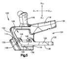
図5~図8を参照すると、間隙124が内側表面102及び外側表面104を貫通する実施形態では、後方本体部分128、したがって骨切りガイド100は、近位アーム130と、近位アーム130から遠位方向Ddに関してオフセットされた遠位アーム132とを含むことができる。近位アーム130及び遠位アーム132は、間隙124によって互いに分離され得る。近位アーム130は、前方本体部分126から後方端108に向かって延在し得る。したがって、近位アーム130は、前方本体部分126に取り付けられた第1の端部と、後方方向Dpoに沿って第1の端部から離間した第2の端部とを有することができる。第2の端部は、近位アーム130の自由端であってもよい。同様に、遠位アーム132は、前方本体部分126から後方端108に向かって延在し得る。したがって、遠位アーム132は、前方本体部分126に取り付けられた第1の端部と、後方方向Dpoに沿って第1の端部から離間した第2の端部とを有することができる。第2の端部は、遠位アーム132の自由端であってもよい。いくつかの実施形態では、近位アーム130は、近位アーム130が後方端108に向かって延在するとき、遠位アーム132から離れるように角度付けされ得る。第1及び第2のアームのそれぞれの正確な形状は、患者の骨の特定の曲率に基づいて変化し得ることが理解されるであろう。5-8, in embodiments in which
近位アーム130は、近位骨接触領域118の後方部分などの少なくとも一部分を含むことができる。遠位アーム132は、遠位骨接触領域120の後方部分などの少なくとも一部分を含むことができる。近位骨接触領域118は、第1の曲率を有し、遠位骨接触領域120は、第1の曲率とは異なる第2の曲率を有する。例えば、第2の曲率は、第1の曲率よりも大きくてもよい。したがって、遠位骨接触領域120は、図3に見られるように、近位骨接触領域118よりも更に内側に湾曲していてもよい。代替実施形態では、第1の曲率及び第2の曲率は、示されるものと異なってもよく、特定の患者の骨の曲率に基づいて変化してもよいことが理解されるであろう。
図5及び図6を引き続き参照すると、骨切りガイド100は、切断器具をガイドして骨に上向き切り込みを形成するように構成された、少なくとも1つの上向きガイド面を有し得る。上向き切り込みは、例えば、膝蓋腱の後方の脛骨粗面の周りに形成されてもよい。したがって、骨切りガイド100は、骨切りガイド100が骨に固定されたときに少なくとも1つの上向きガイド面のそれぞれが脛骨粗面と位置合わせされるように構成(例えば、サイズ決定及び成形)され得る。少なくとも1つの上向きガイド面のそれぞれは、骨切りガイド100の前方端106に配置され得る。少なくとも1つの上向きガイド面は、第1の上向きガイド面134を含み得る。第1の上向きガイド面134は、近位方向Dpr及び後方方向Dpoに関して角度的にオフセットされた上向き方向に沿って延在することができる。例えば、上向き方向は、近位方向Dprと後方方向Dpoとの間の角度で延在することができる。したがって、第1の上向きガイド面134は、第1の上向きガイド面134が近位端110に向かって延びるにつれて、前方方向Daに向かって角度付けされ得る。第3の壁123は、第1の上向きガイド面134を画定することができる。With continued reference to FIGS. 5 and 6,
いくつかの実施形態では、少なくとも1つの上向きガイド面は、第1の上向きガイド面134からオフセットされてそれらの間に上向き溝114を画定する第2の上向きガイド面136を含むことができる。第2の上向きガイド面136は、上向き切り込み経路を骨内に少なくとも部分的に画定するように、上向き方向に沿って延在することができる。したがって、第2の上向きガイド面136は、第2の上向きガイド面134が近位端110に向かって延びるにつれて、前方方向Daに向かって角度付けされ得る。第1の上向きガイド面134の少なくとも一部分は、第2の上向きガイド面136と間に上向き溝114を画定するように第2の上向きガイド面136に対向し得る。上向き溝114は、切断器具をガイドして骨に上向き切り込みを形成するように構成され得る。いくつかの実施形態では、第2の上向きガイド面136は、第1の上向きガイド面134と実質的に平行であり得る。第1の上向きガイド面134は、上向き方向に沿って、第2の上向きガイド面136よりも大きい長さを有することができるが、本開示の実施形態はそのように限定されない。In some embodiments, the at least one upward guide surface can include a second
第2の上向きガイド面136を有する実施形態では、骨切りガイド100は、第2の上向きガイド面136を画定する上向き脚部135を含み得る。上向き脚部135は、前方本体部分126に取り付けられた第1の端部と、第1の端部から上向き方向に沿ってオフセットされた第2の端部とを有することができる。上向き脚部135は、前方本体部分126と一体化しており、かつモノリシックであってよい。第2の端部は、前方本体部分126又は骨切りガイド100の任意の他の部分への取り付けを含まない自由端とすることができる。上向き溝114は、上向き方向と反対の下降方向に沿って骨切りガイド100内に延在することができる。したがって、上向き溝114の近位端は開放されていてもよく、上向き溝116の遠位端は閉鎖されていてもよく、遠位端は、下降方向に沿って近位端からオフセットされている。代替実施形態では、上向き溝114は、第1の端部に隣接して終端することができる、又は第1の端部及び第2の端部の両方が開放されていてもよいことが理解されるであろう。 In embodiments having a second
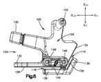
骨切りガイド100は、切断器具をガイドして骨に横断方向の切り込みを形成するように構成された少なくとも1つの横断ガイド面を有することができる。各横断ガイド面は、骨切りガイド100の遠位端112に配置され得る。各横断ガイド面は、遠位方向Doに関して間隙124からオフセットされ得る。例えば、各横断ガイド面は、遠位方向Doに関して遠位骨接触領域120からオフセットされ得る。少なくとも1つの横断ガイド面は、第1の横断ガイド面138を含み得る。第1の横断ガイド面138は、骨内に横断方向切り込み経路を少なくとも部分的に画定するように、前方方向Da及び後方方向Dpoに沿って延在し得る。横断方向切り込み経路は、上向き切り込み経路と交差し得る。
いくつかの実施形態では、少なくとも1つの横断ガイド面は、第1の横断ガイド面138からオフセットされてそれらの間に横断溝116を画定する第2の横断ガイド面140を含むことができる。第2の横断ガイド面140は、前方方向Da及び後方方向Dpoに沿って延在し得る。第1の横断ガイド面138の少なくとも一部分は、それらの間に横断溝116を画定するように、第2の横断ガイド面140に面することができる。横断溝116は、切断器具をガイドして骨に横断方向の切り込みを形成するように構成され得る。切断器具は、上向き切り込みを形成するために使用される切断器具と同じであってもよく、又は異なっていてもよい。いくつかの実施形態では、第2の横断ガイド面140は、第1の横断ガイド面138と実質的に平行であり得る。第1の横断ガイド面138は、後方方向Dpoに沿って、第2の横断ガイド面140よりも大きい長さを有することができるが、本開示の実施形態はそのように限定されない。In some embodiments, the at least one transverse guide surface can include a second
第2の横断ガイド面140を有する実施形態では、骨切りガイド100は、第2の横断ガイド面140を画定する横断脚部139を含み得る。横断脚部139は、前方本体部分126に取り付けられた第1の端部、及び第1の端部から後方方向Dpoに沿ってオフセットされた第2の端部とを有することができる。横断脚部139は、前方本体部分126と一体化しており、かつモノリシックであってよい。第2の端部は、前方本体部分126又は骨切りガイド100の任意の他の部分への取り付けを含まない自由端とすることができる。横断溝114は、前方方向に沿って骨切りガイド100内に延在することができる。したがって、横断溝114の後方端は開放されていてもよく、横断溝114の遠位端は閉鎖されていてもよく、後方端は、下後方方向Dpoに沿って前方端からオフセットされている。代替実施形態では、横断溝116は、第1の端部に隣接して終端することができる、又は第1の端部及び第2の端部の両方が開放されていてもよいことが理解されるであろう。In embodiments having a second
骨切りガイド100は、骨切りガイド100を通って延在する少なくとも1つの固定孔を画定することができる。各固定孔は、骨切りガイド100を骨に取り付けるために、キルシュナーワイヤなどの固定ピンを貫通させて受容するように構成され得る。各固定孔は、骨切りガイド100の内側表面102及び外側表面104を通って延在する。固定孔の位置は、示される実施形態と異なっていてもよいことが理解されるであろう。 The
一実施例では、少なくとも1つの固定孔は、近位方向Dprに関して近位骨接触領域118からオフセットされる近位固定孔142を含むことができる。骨切りガイド100は、前方本体部分126から近位方向Dprに延在するハンドル144を含むことができる。近位固定孔142は、ネック144を通って延在することができる。ネック144は、骨に面するように構成された内側表面145を有し得る。ネック144の内側表面145は、外側方向DOに関して、近位の骨対向面に対してオフセットされ得る。したがって、近位骨対向面が骨と整列されるとき、ネック144の内側表面145は、内側表面145と骨との間に軟組織を収容するように骨から離間され得る。更に、近位固定孔142は、骨に取り付けられる骨固定プレートの孔の位置に対応し得る。したがって、近位固定孔142は、(i)骨切りガイド100を骨に固定する固定ピン、及び(ii)骨の切り込みが拡大された後に骨固定プレートを骨に取り付ける骨アンカー、の両方のために使用される孔を骨に形成するためのガイドとして機能し得る。In one example, the at least one fixation hole can include a
少なくとも1つの固定孔は、少なくとも1つの(例えば2つの)遠位骨固定孔146及び148などを含むことができる。各遠位骨固定孔146及び148は、遠位方向Ddに関して近位骨固定孔142からオフセットされ得る。各遠位骨固定孔146及び148は、骨切りガイド100の前方本体部分126を通って延在し得る。第1の遠位骨固定孔146及び第2の遠位骨固定孔148を有する実施形態では、第1の遠位骨固定孔146は、前方方向Daに沿って第2の遠位骨固定孔148から離間され得る。第1の遠位骨固定孔146と第2の遠位骨固定孔148とは、少なくとも1つの横断ガイド面138と実質的に平行な方向に沿って整列され得る。The at least one fixation hole can include at least one (eg, two) distal bone fixation holes 146 and 148, or the like. Each distal
骨切りガイド100は、前方本体部分126、近位アーム130、遠位アーム132、上向き脚部135、及び横断脚部139を有する一体型本体であり得る。例えば、前方本体部分126、近位アーム130、遠位アーム132、上向き脚部135、及び横断脚部139は、一体であり、互いにモノリシックであり得る。1つのこのような実施例では、骨切りガイド100は、単一のモノリシック本体として3Dプリントされてもよい。骨切りガイド100を単一のモノリシック本体として形成することにより、骨切りガイド100を3Dプリントするコストを制限することができ、製造プロセスを簡略化することができる。代替実施形態では、近位アーム130、遠位アーム132、上向き脚部135、及び横断脚部139のうちの1つ以上は、前方本体部分126に接着、溶接、締結などで取り付けられてもよく、ないしは別の方法で結合されてもよい。骨切りガイド100を一体型本体として提供することにより、骨切りガイド100の取り扱いを単純化することができ、また、2つ以上の可動部分を含み、可動部分の安定性を維持することが困難であり得る従来のガイドよりも切断精度を向上させることができる。
一実施形態では、骨切りガイド100の製造方法は、患者の解剖学的構造の3Dコンピュータモデルを取得することを含み得る。この取得工程は、コンピュータで3Dコンピュータモデルを受信することを含み得る。加えて、又は代替的に、この取得工程は、撮像装置を使用して患者の解剖学的構造の画像を取得することと、画像から患者の解剖学的構造の3Dコンピュータモデルを生成することとを含むことができる。この方法は、患者の解剖学的構造に適合する骨切りガイド100の3Dコンピュータモデルを生成する工程を含み得る。この方法は、骨切りガイド100の3Dコンピュータモデルに基づいて、骨切りガイド100を3Dプリントする工程を含み得る。 In one embodiment, a method of manufacturing
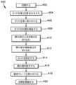
ここで図9~図14を参照して、外科的方法300についてこれから説明する。外科的方法の様々な工程は、異なる医療専門家によって実施され得ることが理解されるであろう。したがって、外科的方法は、互いに別個に実施することができる様々なサブ方法に分割することができる。この方法は、患者の骨300にアクセスするために患者を切開することを含む切開工程402を含み得る。方法は、骨切りガイド100を骨300に位置合わせすることを含む位置合わせ工程404を含み得る。例えば、位置合わせ工程304は、骨300のH点302の周りに遠位骨接触領域120の後方端(例えば、自由端)を引っ掛けることを含み得る。位置合わせ工程304は、骨300の後方隆起部304の周りに遠位骨接触領域120の後方端(例えば、自由端)を引っ掛けることを含み得る。位置合わせ工程304は、少なくとも1つの上向きガイド面134及び/又は溝114を脛骨粗面306と位置合わせすることを含み得る。近位骨対向面が骨300と位置合わせされると、ネック144の内側表面145は、図11に示されるように、内側表面145と骨300との間に軟組織を収容するように骨300から離間され得る。 9-14,
骨切りガイド100が位置合わせされた状態で、骨切りガイド100は、工程406において骨300に取り付けられ得る。取り付けステム406は、キルシュナーワイヤなどの固定ピンを、骨切りガイドの少なくとも1つの固定孔を通して骨に挿入することを含み得る。例えば、固定工程406は、固定ピン202を、少なくとも1つの近位固定孔142を通して骨300に挿入することを含み得る。固定工程406は、固定ピンを、少なくとも1つの遠位固定孔を通して骨300に挿入することを含み得る。例えば、固定工程406は、固定ピン204を、第1の遠位固定孔146を通して骨300に挿入することを含み得る。固定工程408は、固定ピン206を、第2の遠位固定孔148を通して骨300に挿入することを含み得る。 With the
方法400は、骨切りガイド100が正しく位置付けられていることを検証する工程408を含み得る。検証工程408は、骨切りガイド100の位置を検証するためのX線透視法において、X線を使用することを含み得る。方法400は、図13に示されるように、切り込み部307の(図15に表示される)上向き部分308を骨内に形成する工程(工程410)と、図14に示されるように、切り込み部307の(図15に表示される)横断部分310を骨300内に形成する工程(工程412)とを含む。工程410は、工程412の前又は後に実施され得る。上向き切り込み308及び横断方向の切り込み310はそれぞれ、鋸刃208などの切断器具で形成されてもよく、同じ切断器具で又は異なる切断器具で形成されることができる。一実施形態では、鋸刃208は、鋸に取り付けられる近位端(図示せず)と、鋸から挿入方向Dinに沿ってオフセットされた遠位端210とを有することができる。鋸刃208は、その近位端からその遠位端210まで細長くてもよく、その遠位端210に刃先を有することができる。鋸は、挿入方向Dinに垂直な方向に沿って刃208を振動させることができ、挿入方向Dinに沿って骨300に切り込むことができる。鋸刃208の深さは、鋸刃208に取り付けられた停止部を使用して、又は任意の他の好適な技術を使用して、鋸刃208上の深さマーキングを使用して制御され得る。切断器具を収容するために、少なくとも1つの遠位固定ピン204及び206は、図13及び図14に示されるように切断器具の経路の範囲外に屈曲していてもよい。固定ピン204及び206の屈曲は、骨切りガイド100を骨300に更に固定することができる。
図11及び図15を具体的に参照すると、方法は、骨300を切断した後、骨切りガイド100を除去する工程414を含み得る。工程414は、骨切りガイド100を除去する前又は除去した後に、少なくとも1つの遠位固定ピン204及び206を除去することを含み得る。近位固定ピン202は、任意選択的に、定位置に残すことができる。骨切りガイド100を除去した後、この方法は、関節の関節面を再整列させるために、骨内の切り込み部307を拡大することを含み得る。拡大工程414は、骨302の近位部分312が骨314の遠位部分に対して枢動することを可能にするために(骨300の近位部分312と遠位部分314とは、切り込み部307によって分離されている)、たがね又は鋸などの切断器具を使用して切り込み部307を更に拡大することを含み得る。例えば、切り込み部307の上向き部分308及び横断部分310を切り込むとき、切り込みは、骨切りガイド100の、上向き溝114及び下降溝116を閉じる部分(すなわち、アーム135及び139を前方本体部分126に取り付ける部分)を通して形成されなくてもよい。したがって、骨切りガイド100が除去された後、切断器具を使用して切り込み部307の横断部分310を切り込み部307の上向き部分308まで延ばすことができる。拡大工程414は、関節の関節面の所望の補正角度を達成するために、くさび(図示せず)又は他の器具を切り込み部307に挿入することを含み得る。 Referring specifically to FIGS. 11 and 15, the method may include removing 414 the
切り込み部307を拡大した後、工程418で骨300の近位部分312及び遠位部分314に固定プレート500を取り付けて、切り込み部307を拡大された位置に維持することができる。一実施形態では、工程418は、骨プレート500の固定孔502を近位固定ピン202の上に受け入れることによって、固定プレート500を骨300と位置合わせすることを含むことができる(上記に述べたように固定ピン202が定位置に残されている場合)。固定プレート500は、骨アンカーを固定プレート500を通して骨300の近位部分312及び遠位部分314内に挿入することによって骨300に取り付けられ得る。工程420において、切開を閉鎖することができる。 After enlarging the
ある特定の例示の実施形態が記載されてきたが、これらの実施形態は、例示のためのみに提示され、本明細書に開示される発明の範囲を限定することを意図するものではない。したがって、前述のいかなる記載も、いずれかの特定の機構、特性、ステップ、モジュール、又はブロックが必須であるか又は必要不可欠であることを暗示することを意図しない。実際に、本明細書に記載される新規の方法及びシステムは、多様な他の形態で具現化され得る。更に、本明細書に開示される発明の趣旨から逸脱することなく、本明細書に記載される方法及びシステムの形態における様々な省略、置換、及び変更を行うことができる。添付の特許請求の範囲及びそれらの等価物は、本明細書に開示される発明の特定の範囲及び趣旨の範囲内にあるものとして、そのような形態又は変形を網羅することを意図する。 Although certain exemplary embodiments have been described, these embodiments are presented for illustration only and are not intended to limit the scope of the inventions disclosed herein. Thus, nothing in the preceding description is intended to imply that any particular feature, feature, step, module or block is essential or essential. Indeed, the novel methods and systems described herein may be embodied in a variety of other forms. Additionally, various omissions, substitutions and modifications in the form of the methods and systems described herein may be made without departing from the spirit of the inventions disclosed herein. The appended claims and their equivalents are intended to cover such forms or modifications as fall within the specific scope and spirit of the inventions disclosed herein.
本明細書で使用される仮定的な言語、例えば、中でも「することができる(can)」、「することができる(could)」、「し得る(might)」、「し得る(may)」、「例えば(e.g.)」などは、別途具体的に指定されない限り、又は使用される文脈内で別途理解されない限り、一般的に、ある特定の機構、要素、及び/又はステップを、ある特定の実施形態は含み、他の実施形態は含まないことを伝えることを意図する。したがって、そのような仮定的な言語は、一般的に、機構、要素、及び/若しくはステップが、いかなる様式でも1つ以上の実施形態のために必要とされること、又は1つ以上の実施形態が、これらの機構、要素、及び/若しくはステップが任意の特定の実施形態に必ず含まれるか若しくは実施されるかどうかを判断するための論理を、オーサ入力若しくはプロンプティングを伴うか若しくは伴わずに、必ず含むことを暗示することを意図しない。「含む(comprising)」、「含む(including)」、「有する(having)」などの用語は同義であり、非限定的な様式で包括的に使用され、追加の要素、機構、動作、操作などを排除しない。また、「又は」という用語は、使用される場合、例えば、要素の列挙を接続するために、「又は」という用語は、列挙された要素のうちの1つ、いくつか、又は全てを意味するように、その包含的な意味で(かつその排他的な意味ではなく)使用される。 Hypothetical language used herein, e.g., "can", "could", "might", "may", among others , “for example (e.g.),” etc. generally refer to a particular feature, element, and/or step unless specifically specified otherwise or understood otherwise within the context of use. It is meant to convey that some embodiments are inclusive and others are not. Thus, such hypothetical language generally states that features, elements, and/or steps are required for one or more embodiments or that one or more embodiments are required in any manner. but logic to determine whether these features, elements, and/or steps are necessarily included or implemented in any particular embodiment, with or without author input or prompting. , is not intended to imply that the The terms “comprising,” “including,” “having,” etc. are synonymous and are used generically in a non-limiting manner to include additional elements, features, acts, operations, etc. do not exclude Also, when the term "or" is used, e.g., to connect a listing of elements, the term "or" means one, some, or all of the listed elements. is used in its inclusive sense (and not its exclusive sense), as in
〔実施の態様〕
(1) 骨切りガイドであって、
骨に面するように構成された内側表面及び外側方向に沿って前記内側表面と反対側の外側表面であって、前記内側表面及び前記外側表面のそれぞれが、前記骨切りガイドの前方端と前記骨切りガイドの後方端との間に延在し、前記内側表面は、
i)近位骨接触領域と、
ii)遠位骨接触領域であって、1)遠位方向に沿って前記近位骨接触領域から前記遠位骨接触領域まで延在し、かつ、2)前記内側表面から前記外側表面に向かって前記外側方向に沿って延在する、間隙、を画定するように、前記遠位方向に沿って前記近位骨接触領域から離間しており、前記遠位方向が前記外側方向に対して垂直である、遠位骨接触領域と、を画定する、骨に面するように構成された内側表面及び外側方向に沿って前記内側表面と反対側の外側表面と、
少なくとも1つの上向きガイド面であって、前記外側表面と前記内側表面との間に延在し、前記骨内に上向き切り込み経路を少なくとも部分的に画定するように上向き方向に沿って方向付けられており、前記上向き方向が、前記遠位方向、並びに前記遠位方向及び前記外側方向のそれぞれに対して垂直である後方方向から角度的にオフセットされている、少なくとも1つの上向きガイド面と、
少なくとも1つの横断ガイド面であって、前記外側表面と前記内側表面との間に延在し、前記骨内に、前記上向き切り込み経路と交差する横断方向切り込み経路を少なくとも部分的に画定するように横断方向に沿って方向付けられており、前記横断ガイド面が前記遠位方向に沿って前記間隙からオフセットされている、少なくとも1つの横断ガイド面と、を備える、骨切りガイド。
(2) 前記少なくとも1つの上向きガイド面が、第1の上向きガイド面と、前記第1の上向きガイド面からオフセットされて前記第1の上向きガイド面との間に上向き溝を画定する第2の上向きガイド面と、を含む、実施態様1に記載の骨切りガイド。
(3) 前記骨切りガイドの前方部分に取り付けられた第1の端部、及び前記第1の端部から前記上向き方向に沿ってオフセットされた自由端、を有する上向き脚部を備え、前記上向き脚部が、前記第2の上向きガイド面を画定する、実施態様2に記載の骨切りガイド。
(4) 前記上向き溝の近位端が開放され、前記上向き溝の遠位端が閉鎖されるように、前記上向き溝が、前記上向き方向と反対の下降方向に沿って前記骨切りガイド内に延入している、実施態様2に記載の骨切りガイド。
(5) 前記少なくとも1つの横断ガイド面が、第1の横断ガイド面と、前記第1の横断ガイド面からオフセットされて前記第1の横断ガイド面との間に横断溝を画定する第2の横断ガイド面と、を含む、実施態様1に記載の骨切りガイド。[Mode of implementation]
(1) An osteotomy guide,
a medial surface configured to face the bone and a lateral surface opposite the medial surface along a lateral direction, the medial surface and the lateral surface respectively connecting the anterior end of the osteotomy guide and the extending between the posterior end of the osteotomy guide, the inner surface comprising:
i) a proximal bone contacting area;
ii) a distal bone contacting area, 1) extending along a distal direction from the proximal bone contacting area to the distal bone contacting area; and 2) from the inner surface toward the outer surface. spaced apart from the proximal bone contacting region along the distal direction to define a gap extending along the lateral direction, the distal direction being perpendicular to the lateral direction. an inner surface configured to face the bone and an outer surface opposite the inner surface along the lateral direction, defining a distal bone contacting region of
at least one upward guide surface extending between said outer surface and said inner surface and oriented along an upward direction to at least partially define an upward cutting path in said bone; at least one upward guide surface, wherein the upward direction is angularly offset from the distal direction and a posterior direction that is perpendicular to each of the distal and lateral directions;
at least one transverse guide surface extending between the outer surface and the inner surface to at least partially define a transverse cutting path in the bone intersecting the upward cutting path; at least one transverse guide surface oriented along a transverse direction, said transverse guide surface being offset from said gap along said distal direction.
(2) said at least one upward guide surface defines an upward groove between a first upward guide surface and said first upward guide surface offset from said first upward guide surface; 3. The osteotomy guide of embodiment 1, comprising an upwardly facing guide surface.
(3) an upward leg having a first end attached to the anterior portion of the osteotomy guide and a free end offset along the upward direction from the first end; 3. The osteotomy guide of embodiment 2, wherein the leg defines the second upward guiding surface.
(4) the upward groove extends into the osteotomy guide along a downward direction opposite the upward direction such that the proximal end of the upward groove is open and the distal end of the upward groove is closed; 3. The osteotomy guide of embodiment 2, wherein the osteotomy guide is elongated.
(5) said at least one transverse guide surface defines a transverse groove between a first transverse guide surface and said first transverse guide surface offset from said first transverse guide surface; 2. The osteotomy guide of embodiment 1, comprising a transverse guide surface.
(6) 前記骨切りガイドが、前方本体部分と、前記前方本体部分に取り付けられた第1の端部、及び前記第1の端部から前記後方方向に沿ってオフセットされた自由端、を有する横断脚部と、を備え、前記横断脚部が、前記第2の横断ガイド面を画定する、実施態様5に記載の骨切りガイド。
(7) 前記横断溝の後方端が開放され、前記横断溝の前方端が閉鎖されるように、前記横断溝が、前記後方方向と反対の前方方向に沿って前記骨切りガイド内に延入している、実施態様5に記載の骨切りガイド。
(8) 前記横断脚部が、前記前方本体部分と一体である、実施態様5に記載の骨切りガイド。
(9) 第3の骨対向面を備え、前記第3の骨対向面は、前記近位骨対向面と前記遠位骨対向面との間に延在している、実施態様1に記載の骨切りガイド。
(10) 前記間隙が、前記後方端内まで延在し、前記第3の骨対向面で終端している、実施態様9に記載の骨切りガイド。(6) the osteotomy guide having an anterior body portion, a first end attached to the anterior body portion, and a free end offset along the posterior direction from the first end; and a transverse leg, said transverse leg defining said second transverse guide surface.
(7) the transverse groove extends into the osteotomy guide along an anterior direction opposite the posterior direction such that the posterior end of the transverse groove is open and the anterior end of the transverse groove is closed; 6. The osteotomy guide of embodiment 5, wherein the osteotomy guide is
(8) The osteotomy guide of claim 5, wherein said transverse leg is integral with said anterior body portion.
Aspect 9. Aspect 1, comprising a third bone-facing surface, said third bone-facing surface extending between said proximal bone-facing surface and said distal bone-facing surface. osteotomy guide.
Clause 10. The osteotomy guide of clause 9, wherein said gap extends into said posterior end and terminates at said third bone-facing surface.
(11) 前方本体部分と、
前記前方本体部分から前記後方方向に沿って延びる近位アームであって、前記近位骨対向面の少なくとも後方部分を画定する、近位アームと、
前記前方本体部分から前記後方方向に沿って延びる遠位アームであって、前記遠位骨対向面の少なくとも後方部分を画定する、遠位アームと、を備え、前記近位アームと前記遠位アームとが、前記間隙によって互いに分離されている、実施態様1に記載の骨切りガイド。
(12) 骨切り術の切り込みを骨内にガイドするように構成された骨切りガイドであって、
前記骨に面するように構成された内側表面、及び前記内側表面と反対側の外側表面であって、前記内側表面の少なくとも一部分が、前記骨に面するように輪郭付けされている、内側表面及び外側表面と、
上向き方向に沿って延在する上向き切り込み経路を間に画定するように互いに向かい合う第1の上向きガイド面及び第2の上向きガイド面と、
前記上向き切り込み経路と交差する横断方向切り込み経路を間に画定するように互いに向かい合う第1の横断ガイド面及び第2の横断ガイド面と、を備える、骨切りガイド。
(13) 前方本体部分と、
前記前方部分に取り付けられた第1の端部、及び前記第1の端部から前記上向き方向に沿ってオフセットされた自由端、を有する上向き脚部と、を備え、前記上向き脚部が、前記第2の上向きガイド面を画定する、実施態様12に記載の骨切りガイド。
(14) 前記上向き溝の近位端が開放され、前記上向き溝の遠位端が閉鎖されるように、前記上向き溝が、前記上向き方向と反対の下降方向に沿って前記骨切りガイド内に延入している、実施態様12に記載の骨切りガイド。
(15) 前方本体部分と、
前記前方本体部分に取り付けられた第1の端部、及び前記第1の端部から前記後方方向に沿ってオフセットされた自由端、を有する横断脚部と、を備え、前記横断脚部が、前記第2の横断ガイド面を画定する、実施態様12に記載の骨切りガイド。(11) a front body portion;
a proximal arm extending along the posterior direction from the anterior body portion, the proximal arm defining at least a posterior portion of the proximal bone-facing surface;
a distal arm extending along the posterior direction from the anterior body portion, the distal arm defining at least a posterior portion of the distal bone-facing surface; are separated from each other by said gap.
(12) An osteotomy guide configured to guide an osteotomy notch into bone, comprising:
an inner surface configured to face the bone; and an outer surface opposite the inner surface, wherein at least a portion of the inner surface is contoured to face the bone. and an outer surface;
first and second upward guide surfaces facing each other to define an upward cut path extending along an upward direction;
An osteotomy guide comprising first and second transverse guide surfaces facing each other to define therebetween a transverse cutting path that intersects the upward cutting path.
(13) a front body portion;
an upward leg having a first end attached to the forward portion and a free end offset along the upward direction from the first end, wherein the upward leg is connected to the 13. The osteotomy guide of embodiment 12, defining a second upward guide surface.
(14) the upward groove extends into the osteotomy guide along a downward direction opposite the upward direction such that the proximal end of the upward groove is open and the distal end of the upward groove is closed; 13. The osteotomy guide of embodiment 12, which is extended.
(15) a front body portion;
a transverse leg having a first end attached to the forward body portion and a free end offset along the rearward direction from the first end, the transverse leg comprising: 13. The osteotomy guide of embodiment 12, defining the second transverse guide surface.
(16) 前記横断溝の後方端が開放され、前記横断溝の前方端が閉鎖されるように、前記横断溝が、前記後方方向と反対の前方方向に沿って前記骨切りガイド内に延入している、実施態様12に記載の骨切りガイド。
(17) 前記横断脚部が、前記前方本体部分と一体である、実施態様15に記載の骨切りガイド。
(18) 前記内側表面が、
前記前方端と前記後方端との間に延在する近位骨接触領域と、
前記前方端と前記後方端との間に延在し、かつ前記遠位方向に沿って前記近位骨接触領域からオフセットされて前記近位骨接触領域との間に間隙を画定する遠位骨接触領域と、
前記近位骨接触領域と前記遠位骨接触領域との間に延在する前方骨接触領域と、を含む、実施態様12に記載の骨切りガイド。
(19) 前記間隙が、前記後方端内まで延在し、前記前方骨接触領域で終端する、実施態様18に記載の骨切りガイド。
(20) 前方本体部分と、
前記前方本体部分から前記後方方向に沿って延びる近位アームであって、前記近位骨接触領域の少なくとも後方部分を画定する、近位アームと、
前記前方本体部分から前記後方方向に沿って延びる遠位アームであって、前記遠位骨接触領域の少なくとも後方部分を画定する、遠位アームと、を備え、前記近位アームと前記遠位アームとが、前記間隙によって互いに分離されている、実施態様18に記載の骨切りガイド。(16) the transverse groove extends into the osteotomy guide along an anterior direction opposite the posterior direction such that a posterior end of the transverse groove is open and an anterior end of the transverse groove is closed; 13. The osteotomy guide of embodiment 12, wherein
17. The osteotomy guide of claim 15, wherein said transverse leg is integral with said anterior body portion.
(18) the inner surface is
a proximal bone contacting area extending between the anterior end and the posterior end;
a distal bone extending between the anterior end and the posterior end and offset from the proximal bone contacting area along the distal direction to define a gap therebetween; a contact area;
13. The osteotomy guide of embodiment 12, comprising an anterior bone contacting region extending between the proximal bone contacting region and the distal bone contacting region.
Clause 19. The osteotomy guide of clause 18, wherein said gap extends into said posterior end and terminates at said anterior bone contacting area.
(20) a forward body portion;
a proximal arm extending along the posterior direction from the anterior body portion, the proximal arm defining at least a posterior portion of the proximal bone contacting area;
a distal arm extending from the anterior body portion along the posterior direction, the distal arm defining at least a posterior portion of the distal bone contacting area; are separated from each other by said gap.
(21) 骨切りガイドであって、
骨に面するように構成された内側表面及び前記内側表面と反対側の外側表面であって、前記内側表面及び前記外側表面のそれぞれが、前記骨切りガイドの後方端と前記骨切りガイドの前方端との間に延在し、前記内側表面は、内側方向に沿って前記外側表面と反対側であり、前記内側表面は、
i)近位骨接触領域と、
ii)遠位方向に沿って前記近位骨接触領域から離間した遠位骨接触領域と、
iii)前記近位骨接触領域と前記遠位骨接触領域との間に延在する第3の骨接触領域と、を画定し、
前記骨切りガイドが、1)近位骨接触領域、前記遠位骨接触領域、及び前記第3の骨接触領域によって少なくとも部分的に画定され、かつ、2)前記内側方向に沿って前記内側表面から前記外側表面に向かって延在する、間隙を画定し、前記遠位方向が前記内側方向に対して垂直である、骨に面するように構成された内側表面及び前記内側表面と反対側の外側表面と、
少なくとも1つの上向きガイド面であって、前記外側表面と前記内側表面との間に延在し、前記骨内に上向き切り込み経路を少なくとも部分的に画定するように上向き方向に沿って方向付けられており、前記上向き方向が、前記遠位方向、並びに前記遠位方向及び前記内側方向のそれぞれに対して垂直である後方方向から角度的にオフセットされている、少なくとも1つの上向きガイド面と、
少なくとも1つの横断ガイド面であって、前記外側表面と前記内側表面との間に延在し、前記骨内に、前記上向き切り込み経路方向と交差する横断方向切り込み経路を少なくとも部分的に画定するように横断方向に沿って方向付けられている、少なくとも1つの横断ガイド面と、を備える、骨切りガイド。
(22) 前記第3の骨接触領域が、前記近位骨接触領域から前記遠位骨接触領域まで延在している、実施態様21に記載の骨切りガイド。
(23) 前記少なくとも1つの上向きガイド面が、第1の上向きガイド面と、前記第1の上向きガイド面からオフセットされて前記第1の上向きガイド面との間に上向き溝を画定する第2の上向きガイド面と、を含む、実施態様21に記載の骨切りガイド。
(24) 前記骨切りガイドの前方部分に取り付けられた第1の端部、及び前記第1の端部から前記上向き方向に沿ってオフセットされた自由端、を有する上向き脚部を備え、前記上向き脚部が、前記第2の上向きガイド面を画定する、実施態様21に記載の骨切りガイド。
(25) 前記上向き溝の近位端が開放され、前記上向き溝の遠位端が閉鎖されるように、前記上向き溝が、前記上向き方向と反対の下降方向に沿って前記骨切りガイド内に延入している、実施態様21に記載の骨切りガイド。(21) An osteotomy guide comprising:
a medial surface configured to face bone and a lateral surface opposite the medial surface, the medial surface and the lateral surface respectively extending from a posterior end of the osteotomy guide and an anterior end of the osteotomy guide. end, the inner surface being opposite the outer surface along the inner direction, the inner surface comprising:
i) a proximal bone contacting area;
ii) a distal bone contacting area spaced apart from said proximal bone contacting area along a distal direction;
iii) defining a third bone contacting area extending between said proximal bone contacting area and said distal bone contacting area;
The osteotomy guide is defined at least in part by 1) a proximal bone contacting area, a distal bone contacting area, and a third bone contacting area, and 2) the inner surface along the medial direction. an inner surface configured to face the bone defining a gap, wherein the distal direction is perpendicular to the inner direction, and an inner surface opposite the inner surface, extending from the outer surface from an outer surface;
at least one upward guide surface extending between said outer surface and said inner surface and oriented along an upward direction to at least partially define an upward cutting path in said bone; at least one upward guide surface, wherein the upward direction is angularly offset from the distal direction and a posterior direction that is perpendicular to each of the distal and medial directions;
at least one transverse guide surface extending between the outer surface and the inner surface to at least partially define a transverse cutting path in the bone intersecting the upward cutting path direction; at least one transverse guide surface oriented transversely to the osteotomy guide.
22. The osteotomy guide of claim 21, wherein the third bone contacting area extends from the proximal bone contacting area to the distal bone contacting area.
(23) said at least one upward guide surface defines an upward groove between a first upward guide surface and said first upward guide surface offset from said first upward guide surface; 22. The osteotomy guide of embodiment 21, comprising an upwardly facing guide surface.
(24) an upward leg having a first end attached to the anterior portion of the osteotomy guide and a free end offset along the upward direction from the first end; 22. The osteotomy guide of embodiment 21, wherein the leg defines the second upward guiding surface.
(25) the upward groove extends into the osteotomy guide along a downward direction opposite the upward direction such that the proximal end of the upward groove is open and the distal end of the upward groove is closed; 22. The osteotomy guide of embodiment 21, which is extended.
(26) 前記少なくとも1つの横断ガイド面が、第1の横断ガイド面と、前記第1の横断ガイド面からオフセットされて前記第1の横断ガイド面との間に横断溝を画定する第2の横断ガイド面と、を含む、実施態様21に記載の骨切りガイド。
(27) 前記骨切りガイドが、前方本体部分と、前記前方本体部分に取り付けられた第1の端部、及び前記第1の端部から前記後方方向に沿ってオフセットされた自由端、を有する横断脚部と、を備え、前記横断脚部が、前記第2の横断ガイド面を画定する、実施態様26に記載の骨切りガイド。
(28) 前記横断溝の後方端が開放され、前記横断溝の前方端が閉鎖されるように、前記横断溝が、前記後方方向と反対の前方方向に沿って前記骨切りガイド内に延入している、実施態様26に記載の骨切りガイド。
(29) 前記横断脚部が、前記前方本体部分と一体である、実施態様26に記載の骨切りガイド。
(30) 前記間隙が、前記後方端内まで延在し、前記第3の骨対向面で終端する、実施態様21に記載の骨切りガイド。(26) said at least one transverse guide surface defines a transverse groove between a first transverse guide surface and said first transverse guide surface offset from said first transverse guide surface; 22. The osteotomy guide of embodiment 21, comprising a transverse guide surface.
(27) The osteotomy guide has an anterior body portion, a first end attached to the anterior body portion, and a free end offset from the first end along the posterior direction. and a transverse leg, said transverse leg defining said second transverse guide surface.
(28) the transverse groove extends into the osteotomy guide along an anterior direction opposite the posterior direction such that a posterior end of the transverse groove is open and an anterior end of the transverse groove is closed; 27. The osteotomy guide according to embodiment 26, wherein
29. The osteotomy guide of claim 26, wherein the transverse leg is integral with the anterior body portion.
Clause 30. The osteotomy guide of clause 21, wherein the gap extends into the posterior end and terminates at the third bone-facing surface.
Claims (9)
Translated fromJapanese横断方向に沿って互いに離間された前方端(106)及び後方端(108)と、
前記骨(300)に面するように構成された内側表面(102)及び外側方向に沿って前記内側表面と反対側の外側表面(104)であって、前記内側表面及び前記外側表面のそれぞれが、前記前方端と前記後方端との間に延在する、内側表面及び外側表面と、
少なくとも1つの横断ガイド面(138、140)であって、前記外側表面と前記内側表面との間に延在し、前記骨内に横断方向切り込み経路を少なくとも部分的に画定するように横断方向に沿って方向付けられている、少なくとも1つの横断ガイド面と、を備え、
前記内側表面が、i)第1の骨接触領域(118)と、ii)前記第1の骨接触領域から離間して前記第1の骨接触領域との間に間隙(124)を画定する第2の骨接触領域(120)と、を画定し、前記少なくとも1つの横断ガイド面が、遠位方向において前記間隙から離間しており、
前記少なくとも1つの横断ガイド面が、第1の横断ガイド面(138)と、前記第1の横断ガイド面からオフセットされて前記第1の横断ガイド面との間に横断溝(116)を画定する第2の横断ガイド面(140)と、を含み、前記横断溝が、前記遠位方向において前記間隙から離間しており、
前記骨切りガイドの前記内側表面及び前記外側表面を通って延在し、前記骨切りガイドを前記骨に取り付けるために、第1の固定ピンを貫通させて受容する少なくとも1つの近位固定孔(142)と、
前記少なくとも1つの近位固定孔から前記遠位方向に離間しており、前記骨切りガイドの前記内側表面及び前記外側表面を通って延在し、前記骨切りガイドを前記骨に取り付けるために、第2の固定ピンを貫通させて受容する少なくとも1つの遠位固定孔(146、148)と、を更に備える、骨切りガイド。An osteotomy guide configured to guide a bone cut, comprising:
a forward end (106) and a rearward end (108) spaced apart from each other along a transverse direction;
an inner surface (102) configured to face said bone (300) and an outer surface (104) opposite said inner surface along a lateral direction, said inner surface and said outer surface each comprising: , an inner surface and an outer surface extending between said forward end and said rearward end;
at least one transverse guide surface (138, 140) extending between said outer surface and said inner surface and extending transversely to at least partially define a transverse cut path within said bone; at least one transverse guide surface orientedalong
said inner surface defining a gap (124) between i) a first bone contacting area (118) and ii) spaced from said first bone contacting area and said first bone contacting area; defining two bone contacting areas (120), wherein the at least one transverse guide surface is distally spaced apart from the gap;
The at least one transverse guide surface defines a transverse groove (116) between a first transverse guide surface (138) and the first transverse guide surface offset from the first transverse guide surface. a second transverse guide surface (140), wherein the transverse groove is spaced from the gap in the distal direction;
at least one proximal fixation hole ( 142) and
distally spaced from the at least one proximal fixation hole and extending through the inner and outer surfaces of the osteotomy guide for attaching the osteotomy guide to the bone; and at least one distal fixation hole (146, 148) for receiving a second fixation pin therethrough .
Applications Claiming Priority (1)
| Application Number | Priority Date | Filing Date | Title |
|---|---|---|---|
| PCT/CN2019/082425WO2020206674A1 (en) | 2019-04-12 | 2019-04-12 | Osteotomy guide |
Publications (2)
| Publication Number | Publication Date |
|---|---|
| JP2022530325A JP2022530325A (en) | 2022-06-29 |
| JP7297926B2true JP7297926B2 (en) | 2023-06-26 |
Family
ID=72750830
Family Applications (2)
| Application Number | Title | Priority Date | Filing Date |
|---|---|---|---|
| JP2021560049AActiveJP7297926B2 (en) | 2019-04-12 | 2019-04-12 | osteotomy guide |
| JP2021560051AActiveJP7383726B2 (en) | 2019-04-12 | 2019-08-23 | osteotomy guide |
Family Applications After (1)
| Application Number | Title | Priority Date | Filing Date |
|---|---|---|---|
| JP2021560051AActiveJP7383726B2 (en) | 2019-04-12 | 2019-08-23 | osteotomy guide |
Country Status (6)
| Country | Link |
|---|---|
| US (2) | US12324591B2 (en) |
| EP (2) | EP3952758A4 (en) |
| JP (2) | JP7297926B2 (en) |
| KR (2) | KR20210149825A (en) |
| CN (2) | CN114206237B (en) |
| WO (2) | WO2020206674A1 (en) |
Families Citing this family (4)
| Publication number | Priority date | Publication date | Assignee | Title |
|---|---|---|---|---|
| US20230293191A1 (en)* | 2022-03-21 | 2023-09-21 | Ritesh R. Shah | Medial biased patient-specific instrumentation and related methods |
| CN116473620B (en)* | 2023-04-25 | 2025-01-21 | 江苏世康启航医疗器械有限公司 | Unicompartmental replacement osteotomy guide positioning module and unicompartmental replacement osteotomy guide positioning system |
| CN117297710B (en)* | 2023-11-05 | 2025-02-21 | 中国人民解放军陆军军医大学第一附属医院 | Tibia osteotomy guiding protection device based on 3DP technology and assembly method thereof |
| CN119055314A (en)* | 2024-08-27 | 2024-12-03 | 杭州柳叶刀机器人有限公司 | Osteotomy guide and method of using the same |
Citations (7)
| Publication number | Priority date | Publication date | Assignee | Title |
|---|---|---|---|---|
| JP2008529607A (en) | 2005-02-08 | 2008-08-07 | アイバランス・メディカル・インコーポレーテッド | Method and apparatus for forming a wedge-shaped opening in a bone for wedge osteotomy |
| JP2010540123A (en) | 2007-09-30 | 2010-12-24 | デピュイ・プロダクツ・インコーポレイテッド | Customized patient-specific orthopedic surgical instruments |
| US20150305752A1 (en) | 2014-04-25 | 2015-10-29 | Biomet Manufacturing, Llc | HTO Guide With Optional Guided ACL/PCL Tunnels |
| CN107320153A (en) | 2017-08-17 | 2017-11-07 | 江苏奥康尼医疗科技发展有限公司 | A kind of tibial medial Osteotomy aid |
| US20170325826A1 (en) | 2014-11-13 | 2017-11-16 | Episurf Ip-Management Ab | Surgical kit for repair of articular surfaces in the talocrural joint including surgical saw guide |
| JP2019034120A (en) | 2016-08-19 | 2019-03-07 | エイ プラス バイオテクノロジー カンパニー リミテッドA Plus Biotechnology Company Limited | Osteotomy instrument |
| JP2019202108A (en) | 2018-05-25 | 2019-11-28 | 光原科技股▲分▼有限公司 | Osteotomy jig |
Family Cites Families (23)
| Publication number | Priority date | Publication date | Assignee | Title |
|---|---|---|---|---|
| JP3100455B2 (en) | 1992-03-13 | 2000-10-16 | 富久 腰野 | Wedge spacer material for osteotomy fixation and fusion promotion |
| US5423827A (en) | 1994-06-02 | 1995-06-13 | Intermedics Orthopedics, Inc. | Surgical jig for femoral knee prosthesis |
| GB0219342D0 (en) | 2002-08-20 | 2002-09-25 | Depuy Int Ltd | A guide block for use in surgery |
| US7309339B2 (en)* | 2003-02-04 | 2007-12-18 | Howmedica Osteonics Corp. | Apparatus for aligning an instrument during a surgical procedure |
| US8083746B2 (en) | 2004-05-07 | 2011-12-27 | Arthrex, Inc. | Open wedge osteotomy system and surgical method |
| US8241292B2 (en) | 2006-06-30 | 2012-08-14 | Howmedica Osteonics Corp. | High tibial osteotomy system |
| GB0913674D0 (en) | 2009-08-06 | 2009-09-16 | Depuy Ireland | Surgical instrument and system of surgical instrument |
| BR112013009069A2 (en)* | 2010-10-14 | 2016-07-19 | Smith & Nephew Inc | patient-attached instrumentation and methods |
| TR201809866T4 (en) | 2013-11-03 | 2018-07-23 | Ignite Concepts Gmbh | Osteotomy implant. |
| US9833245B2 (en) | 2014-09-29 | 2017-12-05 | Biomet Sports Medicine, Llc | Tibial tubercule osteotomy |
| CN104825215B (en)* | 2015-05-22 | 2017-03-15 | 北京爱康宜诚医疗器材股份有限公司 | Osteotomy guide plate |
| CN104825214B (en) | 2015-05-22 | 2017-12-19 | 北京爱康宜诚医疗器材股份有限公司 | Osteotomy locating guider |
| CN105193475B (en)* | 2015-08-18 | 2017-07-07 | 长沙市第三医院 | Individuation osteotomy guide plate external member and its method for designing |
| CN205359552U (en) | 2015-12-11 | 2016-07-06 | 陈俊名 | High-position tibia osteotomy surgical instrument |
| CN205339051U (en) | 2016-01-25 | 2016-06-29 | 上海昕健医疗技术有限公司 | Cut bone guiding piece |
| CA2969998A1 (en)* | 2016-06-17 | 2017-12-17 | Socovar, L.P. | Limb sparing in mammals using patient-specific endoprostheses and cutting guides |
| CN206333941U (en) | 2016-08-19 | 2017-07-18 | 骆主安 | Osteotomy surgical instrument |
| CN107753088B (en) | 2016-08-19 | 2020-07-03 | 爱派司生技股份有限公司 | An osteotomy surgical instrument |
| JP7044545B2 (en) | 2017-01-13 | 2022-03-30 | 住友化学株式会社 | Methods for Producing Compounds, Resins, Resist Compositions and Resist Patterns |
| CN207532417U (en) | 2017-05-18 | 2018-06-26 | 聂宇 | Shin bone list condyle osteotomy device |
| FR3070249B1 (en) | 2017-08-22 | 2023-01-27 | Newclip Int | SURGICAL GUIDING DEVICE, TO ASSIST AN OPENING OSTEOTOMY TECHNIQUE |
| TWI638633B (en) | 2017-11-22 | 2018-10-21 | 愛派司生技股份有限公司 | Osteotomy device with an in-vitro alignment component |
| CN109512484B (en) | 2018-09-20 | 2021-03-16 | 上海昕健医疗技术有限公司 | Tibial Orthopedic Osteotomy Guide |
- 2019
- 2019-04-12KRKR1020217036570Apatent/KR20210149825A/ennot_activeCeased
- 2019-04-12EPEP19924333.8Apatent/EP3952758A4/enactivePending
- 2019-04-12USUS17/602,430patent/US12324591B2/enactiveActive
- 2019-04-12CNCN201980095370.9Apatent/CN114206237B/enactiveActive
- 2019-04-12JPJP2021560049Apatent/JP7297926B2/enactiveActive
- 2019-04-12WOPCT/CN2019/082425patent/WO2020206674A1/ennot_activeCeased
- 2019-08-23EPEP19924317.1Apatent/EP3952757A4/enactivePending
- 2019-08-23WOPCT/CN2019/102153patent/WO2020206902A1/ennot_activeCeased
- 2019-08-23USUS17/602,443patent/US12357321B2/enactiveActive
- 2019-08-23JPJP2021560051Apatent/JP7383726B2/enactiveActive
- 2019-08-23KRKR1020217036574Apatent/KR102801731B1/enactiveActive
- 2019-08-23CNCN201980097389.7Apatent/CN114206238B/enactiveActive
Patent Citations (7)
| Publication number | Priority date | Publication date | Assignee | Title |
|---|---|---|---|---|
| JP2008529607A (en) | 2005-02-08 | 2008-08-07 | アイバランス・メディカル・インコーポレーテッド | Method and apparatus for forming a wedge-shaped opening in a bone for wedge osteotomy |
| JP2010540123A (en) | 2007-09-30 | 2010-12-24 | デピュイ・プロダクツ・インコーポレイテッド | Customized patient-specific orthopedic surgical instruments |
| US20150305752A1 (en) | 2014-04-25 | 2015-10-29 | Biomet Manufacturing, Llc | HTO Guide With Optional Guided ACL/PCL Tunnels |
| US20170325826A1 (en) | 2014-11-13 | 2017-11-16 | Episurf Ip-Management Ab | Surgical kit for repair of articular surfaces in the talocrural joint including surgical saw guide |
| JP2019034120A (en) | 2016-08-19 | 2019-03-07 | エイ プラス バイオテクノロジー カンパニー リミテッドA Plus Biotechnology Company Limited | Osteotomy instrument |
| CN107320153A (en) | 2017-08-17 | 2017-11-07 | 江苏奥康尼医疗科技发展有限公司 | A kind of tibial medial Osteotomy aid |
| JP2019202108A (en) | 2018-05-25 | 2019-11-28 | 光原科技股▲分▼有限公司 | Osteotomy jig |
Also Published As
| Publication number | Publication date |
|---|---|
| EP3952757A4 (en) | 2023-01-04 |
| US12357321B2 (en) | 2025-07-15 |
| KR102801731B1 (en) | 2025-04-30 |
| CN114206237B (en) | 2024-05-03 |
| JP2022530325A (en) | 2022-06-29 |
| EP3952758A1 (en) | 2022-02-16 |
| US12324591B2 (en) | 2025-06-10 |
| US20220211388A1 (en) | 2022-07-07 |
| WO2020206902A1 (en) | 2020-10-15 |
| EP3952758A4 (en) | 2022-12-07 |
| US20220167992A1 (en) | 2022-06-02 |
| EP3952757A1 (en) | 2022-02-16 |
| KR20210149827A (en) | 2021-12-09 |
| CN114206238B (en) | 2024-11-19 |
| JP7383726B2 (en) | 2023-11-20 |
| CN114206237A (en) | 2022-03-18 |
| CN114206238A (en) | 2022-03-18 |
| JP2022528939A (en) | 2022-06-16 |
| KR20210149825A (en) | 2021-12-09 |
| WO2020206674A1 (en) | 2020-10-15 |
Similar Documents
| Publication | Publication Date | Title |
|---|---|---|
| US20230346391A1 (en) | Surgical Kit for Tibial Resection and Replacement | |
| US11026699B2 (en) | Tibial tubercule osteotomy | |
| JP7297926B2 (en) | osteotomy guide | |
| EP3400888B1 (en) | Surgical device for osteotomy | |
| US10849632B2 (en) | Surgical methods of osteotomy device with an In-vitro alignment component | |
| KR102183848B1 (en) | Universal osteotomy device |
Legal Events
| Date | Code | Title | Description |
|---|---|---|---|
| A521 | Request for written amendment filed | Free format text:JAPANESE INTERMEDIATE CODE: A523 Effective date:20220217 | |
| A621 | Written request for application examination | Free format text:JAPANESE INTERMEDIATE CODE: A621 Effective date:20220217 | |
| A977 | Report on retrieval | Free format text:JAPANESE INTERMEDIATE CODE: A971007 Effective date:20230127 | |
| A131 | Notification of reasons for refusal | Free format text:JAPANESE INTERMEDIATE CODE: A131 Effective date:20230214 | |
| A521 | Request for written amendment filed | Free format text:JAPANESE INTERMEDIATE CODE: A523 Effective date:20230512 | |
| TRDD | Decision of grant or rejection written | ||
| A01 | Written decision to grant a patent or to grant a registration (utility model) | Free format text:JAPANESE INTERMEDIATE CODE: A01 Effective date:20230530 | |
| A61 | First payment of annual fees (during grant procedure) | Free format text:JAPANESE INTERMEDIATE CODE: A61 Effective date:20230614 | |
| R150 | Certificate of patent or registration of utility model | Ref document number:7297926 Country of ref document:JP Free format text:JAPANESE INTERMEDIATE CODE: R150 |