JP7296477B2 - Biological sample analyzer with forced air convection plenum - Google Patents
Biological sample analyzer with forced air convection plenumDownload PDFInfo
- Publication number
- JP7296477B2 JP7296477B2JP2021556724AJP2021556724AJP7296477B2JP 7296477 B2JP7296477 B2JP 7296477B2JP 2021556724 AJP2021556724 AJP 2021556724AJP 2021556724 AJP2021556724 AJP 2021556724AJP 7296477 B2JP7296477 B2JP 7296477B2
- Authority
- JP
- Japan
- Prior art keywords
- receptacle
- plenum
- biological sample
- air
- heater
- Prior art date
- Legal status (The legal status is an assumption and is not a legal conclusion. Google has not performed a legal analysis and makes no representation as to the accuracy of the status listed.)
- Active
Links
- 239000012472biological sampleSubstances0.000titleclaimsdescription156
- 238000000034methodMethods0.000claimsdescription30
- 238000004891communicationMethods0.000claimsdescription10
- 239000012530fluidSubstances0.000claimsdescription4
- 230000008569processEffects0.000claimsdescription4
- 238000010438heat treatmentMethods0.000description34
- 239000000523sampleSubstances0.000description13
- 239000003153chemical reaction reagentSubstances0.000description7
- DDRJAANPRJIHGJ-UHFFFAOYSA-NcreatinineChemical compoundCN1CC(=O)NC1=NDDRJAANPRJIHGJ-UHFFFAOYSA-N0.000description6
- 230000033001locomotionEffects0.000description6
- 238000003780insertionMethods0.000description5
- 230000037431insertionEffects0.000description5
- 238000004364calculation methodMethods0.000description4
- 238000005259measurementMethods0.000description4
- 102000009027AlbuminsHuman genes0.000description3
- 108010088751AlbuminsProteins0.000description3
- 238000001816coolingMethods0.000description3
- 229940109239creatinineDrugs0.000description3
- 238000010586diagramMethods0.000description3
- 230000006870functionEffects0.000description3
- 238000012546transferMethods0.000description3
- 102000001554HemoglobinsHuman genes0.000description2
- 108010054147HemoglobinsProteins0.000description2
- 230000002411adverseEffects0.000description2
- 239000004020conductorSubstances0.000description2
- 230000003247decreasing effectEffects0.000description2
- 230000001934delayEffects0.000description2
- 230000003287optical effectEffects0.000description2
- 238000013021overheatingMethods0.000description2
- 230000000007visual effectEffects0.000description2
- 229910000838Al alloyInorganic materials0.000description1
- RYGMFSIKBFXOCR-UHFFFAOYSA-NCopperChemical compound[Cu]RYGMFSIKBFXOCR-UHFFFAOYSA-N0.000description1
- 239000004642PolyimideSubstances0.000description1
- 230000009471actionEffects0.000description1
- 230000004913activationEffects0.000description1
- 230000006978adaptationEffects0.000description1
- 230000004520agglutinationEffects0.000description1
- XAGFODPZIPBFFR-UHFFFAOYSA-NaluminiumChemical compound[Al]XAGFODPZIPBFFR-UHFFFAOYSA-N0.000description1
- 229910052782aluminiumInorganic materials0.000description1
- 239000012491analyteSubstances0.000description1
- 230000006399behaviorEffects0.000description1
- 239000008280bloodSubstances0.000description1
- 210000004369bloodAnatomy0.000description1
- 230000008859changeEffects0.000description1
- 230000015271coagulationEffects0.000description1
- 238000005345coagulationMethods0.000description1
- 239000010949copperSubstances0.000description1
- 229910052802copperInorganic materials0.000description1
- 238000013461designMethods0.000description1
- 238000001514detection methodMethods0.000description1
- 230000001815facial effectEffects0.000description1
- 239000000463materialSubstances0.000description1
- 230000007246mechanismEffects0.000description1
- 239000000203mixtureSubstances0.000description1
- 238000012544monitoring processMethods0.000description1
- 239000002245particleSubstances0.000description1
- 229920001721polyimidePolymers0.000description1
- 238000002360preparation methodMethods0.000description1
- 230000004044responseEffects0.000description1
- 230000002207retinal effectEffects0.000description1
- 230000007704transitionEffects0.000description1
- 238000011144upstream manufacturingMethods0.000description1
- 210000002700urineAnatomy0.000description1
- 239000002699waste materialSubstances0.000description1
Images


Classifications
- G—PHYSICS
- G01—MEASURING; TESTING
- G01N—INVESTIGATING OR ANALYSING MATERIALS BY DETERMINING THEIR CHEMICAL OR PHYSICAL PROPERTIES
- G01N35/00—Automatic analysis not limited to methods or materials provided for in any single one of groups G01N1/00 - G01N33/00; Handling materials therefor
- G01N35/00029—Automatic analysis not limited to methods or materials provided for in any single one of groups G01N1/00 - G01N33/00; Handling materials therefor provided with flat sample substrates, e.g. slides
- G—PHYSICS
- G01—MEASURING; TESTING
- G01N—INVESTIGATING OR ANALYSING MATERIALS BY DETERMINING THEIR CHEMICAL OR PHYSICAL PROPERTIES
- G01N35/00—Automatic analysis not limited to methods or materials provided for in any single one of groups G01N1/00 - G01N33/00; Handling materials therefor
- G01N2035/00346—Heating or cooling arrangements
- G01N2035/00356—Holding samples at elevated temperature (incubation)
- G01N2035/00366—Several different temperatures used
- G—PHYSICS
- G01—MEASURING; TESTING
- G01N—INVESTIGATING OR ANALYSING MATERIALS BY DETERMINING THEIR CHEMICAL OR PHYSICAL PROPERTIES
- G01N35/00—Automatic analysis not limited to methods or materials provided for in any single one of groups G01N1/00 - G01N33/00; Handling materials therefor
- G01N2035/00346—Heating or cooling arrangements
- G01N2035/00356—Holding samples at elevated temperature (incubation)
- G01N2035/00376—Conductive heating, e.g. heated plates
- G—PHYSICS
- G01—MEASURING; TESTING
- G01N—INVESTIGATING OR ANALYSING MATERIALS BY DETERMINING THEIR CHEMICAL OR PHYSICAL PROPERTIES
- G01N35/00—Automatic analysis not limited to methods or materials provided for in any single one of groups G01N1/00 - G01N33/00; Handling materials therefor
- G01N2035/00346—Heating or cooling arrangements
- G01N2035/00356—Holding samples at elevated temperature (incubation)
- G01N2035/00386—Holding samples at elevated temperature (incubation) using fluid heat transfer medium
- G—PHYSICS
- G01—MEASURING; TESTING
- G01N—INVESTIGATING OR ANALYSING MATERIALS BY DETERMINING THEIR CHEMICAL OR PHYSICAL PROPERTIES
- G01N35/00—Automatic analysis not limited to methods or materials provided for in any single one of groups G01N1/00 - G01N33/00; Handling materials therefor
- G01N2035/00346—Heating or cooling arrangements
- G01N2035/00435—Refrigerated reagent storage
Landscapes
- Physics & Mathematics (AREA)
- Health & Medical Sciences (AREA)
- Life Sciences & Earth Sciences (AREA)
- Chemical & Material Sciences (AREA)
- Analytical Chemistry (AREA)
- Biochemistry (AREA)
- General Health & Medical Sciences (AREA)
- General Physics & Mathematics (AREA)
- Immunology (AREA)
- Pathology (AREA)
- Automatic Analysis And Handling Materials Therefor (AREA)
Description
Translated fromJapanese本出願は、2019年3月22日出願の米国仮出願第62/822,391号の優先権を主張し、その開示内容は全体を参照によって本明細書に組み入れる。 This application claims priority to US Provisional Application No. 62/822,391, filed March 22, 2019, the disclosure of which is incorporated herein by reference in its entirety.
関連出願の相互参照
本出願は、本出願と同日に代理人整理番号2019P06410WOとして出願された米国特許出願第62/822,371号明細書、および本出願と同日に代理人整理番号2019P06411WOとして出願された米国特許出願第62/822,379号明細書に関連しており、これら両方の教示内容は、それらの全体が本明細書に記載されているかのように、参照によって本明細書に組み入れる。CROSS REFERENCE TO RELATED APPLICATIONS This application is filed on the same date as this application as Attorney Docket No. 2019P06410WO, and is filed as Attorney Docket No. 2019P06411WO on the same date as this application. No. 62/822,379, the teachings of both of which are hereby incorporated by reference as if set forth in their entireties.
本開示は、一般に、生体試料分析装置に関し、より詳細には、生体試料分析装置において使用される消耗品生体試料ホルダの加熱に関する。 FIELD OF THE DISCLOSURE The present disclosure relates generally to biological sample analyzers and, more particularly, to heating consumable biological sample holders used in biological sample analyzers.
ポイントオブケアのサービスでは、血液や尿といった患者の生体試料を分析するために、ベンチトップ型の生体試料分析装置が一般に使用される。通常、生体試料は、中に試薬を有するカートリッジ内に供給される。そのカートリッジが分析装置に挿入され、分析装置が、試料と試薬を混合するようにカートリッジを動かす。さらに、分析装置は、試料および試薬を、通常は室温より高い目標温度に加熱し、次いで加熱された試料を分析する。 In point-of-care services, benchtop biological sample analyzers are commonly used to analyze patient biological samples such as blood and urine. Typically, biological samples are supplied in cartridges having reagents therein. The cartridge is inserted into the analyzer, which moves the cartridge to mix the sample and reagents. Additionally, the analyzer heats the sample and reagents to a target temperature, usually above room temperature, and then analyzes the heated sample.
上の概要および以下の詳細な説明は、添付図面と併せ読めば、よりよく理解されよう。図面は、本開示の例示的実施形態を示す。しかし、本明細書は、示してある詳細な構成および手段に限定されないことを理解されたい。 The above general description and the following detailed description are better understood when read in conjunction with the accompanying drawings. The drawings illustrate exemplary embodiments of the present disclosure. It should be understood, however, that the specification is not limited to the precise arrangements and instrumentalities shown.
従来の生体試料分析装置では、分析装置のヒータは、生体試料および試薬を保持しているカートリッジ、カード、またはカセットなどの診断消耗品ホルダに、目標温度を適用するように設定される。この目標温度は、生体試料が分析されることになる温度に対応しており、通常は周囲温度または室温より高い。次いで、診断消耗品ホルダは、目標温度に到達することができる。しかし、診断消耗品ホルダをこのように加熱することには時間がかかることがあり、それにより試料の分析結果を得るのに必要な時間が長くなる。したがって、診断消耗品ホルダを目標温度まで加熱するのに必要な時間量を短縮することが望まれている。必要な時間量を短縮する1つの方法は、診断消耗品ホルダをより小さい質量になるよう再設計することであり、このより小さい質量は、より大きい質量を有する診断消耗品ホルダよりも、所与の温度においてより早く加熱される。しかし、診断消耗品ホルダを再設計すると、未使用の診断消耗品ホルダが不用品になってしまい、生体試料分析装置の再設計も必要になる可能性がある。 In conventional biological sample analyzers, the heater of the analyzer is set to apply a target temperature to a diagnostic consumable holder such as a cartridge, card, or cassette holding the biological sample and reagents. This target temperature corresponds to the temperature at which the biological sample is to be analyzed and is typically above ambient or room temperature. The diagnostic consumable holder can then reach the target temperature. However, heating the diagnostic consumable holder in this manner can be time consuming, thereby increasing the time required to obtain analytical results for the sample. Accordingly, it is desirable to reduce the amount of time required to heat a diagnostic consumable holder to a target temperature. One way to reduce the amount of time required is to redesign the diagnostic consumable holder to have a smaller mass, which is more efficient for a given diagnostic consumable holder than a diagnostic consumable holder with a larger mass. at the temperature of . However, redesigning the diagnostic consumable holder may result in unused diagnostic consumable holders becoming waste, and may also require a redesign of the biological sample analyzer.
代替形態として、目標温度を上回る高温度を適用するように分析装置の少なくとも1つのヒータを設定することにより、診断消耗品ホルダの加熱を加速するように生体試料分析装置を構成することができる。いくつかの実施形態では、高温度は、少なくとも1つのヒータの最大加熱性能に対応してよい。しかし、目標温度を超えて診断消耗品ホルダを過剰に加熱しないように注意を払う必要がある。したがって、診断消耗品ホルダが目標温度を超える前に、少なくとも1つのヒータを急速に冷却するように、生体試料分析装置を構成することができる。以下に説明するように、これは、少なくとも1つのヒータによって加えられる加熱を低減することによって、少なくとも部分的に達成可能である。追加として、または代替として、診断消耗品ホルダが目標温度を超える前の所定の時間に、空気を強制的に試料分析装置の少なくとも1つのヒータに行き渡らせることをファンに行わせることにより、急速な冷却を達成して、少なくとも1つのヒータを目標温度に冷却することができる。このファンは、少なくとも1つのヒータが高温度に加熱しているときには第1の速度で動作することができ、ヒータが目標温度に加熱しているときには、第1の速度より速い第2の速度で動作することができる。第1の速度は、ゼロまたはゼロ以上とすることができ、したがって第1の速度のとき、ファンは動いていてもオフであってもよい。ファンからの空気は、試料分析装置内に配置されたプレナムを通って、ヒータに行き渡るように方向付けることができる。 Alternatively, the biological sample analyzer can be configured to accelerate heating of the diagnostic consumable holder by setting at least one heater of the analyzer to apply an elevated temperature above the target temperature. In some embodiments, the high temperature may correspond to maximum heating capability of the at least one heater. However, care must be taken not to overheat the diagnostic consumable holder beyond the target temperature. Accordingly, the biological sample analyzer can be configured to rapidly cool the at least one heater before the diagnostic consumable holder exceeds a target temperature. As explained below, this can be achieved, at least in part, by reducing the heating applied by at least one heater. Additionally or alternatively, by having the fan force air across at least one heater of the sample analyzer a predetermined time before the diagnostic consumable holder exceeds the target temperature, rapid Cooling can be achieved to cool the at least one heater to a target temperature. The fan is operable at a first speed when the at least one heater is heating to a high temperature and at a second speed greater than the first speed when the heater is heating to a target temperature. can work. The first speed may be zero or greater than zero, so the fan may be running or off when at the first speed. Air from the fan can be directed across the heater through a plenum located within the sample analyzer.
診断消耗品ホルダは、室温に保たれると、保存期間が相対的に短くなることがある(例えば、おおよそ8週間)。これは、少なくとも部分的に、診断消耗品ホルダに保持または含まれている試薬の保存期間に起因することがある。したがって、診断消耗品ホルダの保存期間を(例えば、おおよそ2年まで)延ばすために、診断消耗品ホルダは冷蔵することができる。しかし、従来の生体試料分析装置は、通常、冷蔵された診断消耗品ホルダの低下した温度を考慮しない。その結果、診断消耗品ホルダを室温にするために、診断消耗品ホルダは、従来の生体試料分析装置に挿入される前に一定の期間(例えば30分)にわたって、冷蔵庫から取り出されていなくてはならない。 A diagnostic consumable holder may have a relatively short shelf life (eg, approximately eight weeks) when kept at room temperature. This may be due, at least in part, to the shelf life of the reagents held or contained in the diagnostic consumable holder. Accordingly, to extend the shelf life of the diagnostic consumable holder (eg, up to approximately two years), the diagnostic consumable holder can be refrigerated. However, conventional biological sample analyzers typically do not take into account the reduced temperature of refrigerated diagnostic consumable holders. As a result, in order to bring the diagnostic consumable holder to room temperature, the diagnostic consumable holder must be removed from the refrigerator for a period of time (eg, 30 minutes) before being inserted into a conventional biological sample analyzer. not.
診断消耗品ホルダが室温にならなければ、分析装置は、診断消耗品ホルダを目標温度に加熱できないことがある。分析は温度に敏感なので、これにより、生体試料分析装置によって生成された分析結果に偏りや誤差が生じることがある。あるいは、分析装置は、診断消耗品ホルダを受け付けないことがあり、その結果、操作者は患者から新しい試料を取得することが必要になり、それにより遅延が生じることになる。以下に説明するように、本開示の試料分析装置は、冷蔵されていて診断消耗品ホルダが周囲温度範囲まで温まる前に試料分析装置に挿入された診断消耗品ホルダ(本明細書において「低温の消耗品ホルダ」と呼ぶ)を、検出するように構成することができる。本明細書において使用するとき、「低温の消耗品ホルダ」という用語は、周囲温度範囲を下回る消耗品ホルダを指すために使用される。一実施形態において、周囲温度範囲は、セ氏約15度~セ氏約32度とすることができる。別の実施形態では、周囲温度範囲は、セ氏約20度~セ氏約25度の室温範囲である。試料分析装置によって試料が分析される前に、診断消耗品ホルダを目標温度にするために、試料分析装置は、診断消耗品ホルダの加熱を調節するようにさらに構成することができる。 Unless the diagnostic consumable holder is at room temperature, the analyzer may not be able to heat the diagnostic consumable holder to the target temperature. Since analysis is temperature sensitive, this can cause bias and error in the analytical results produced by biological sample analyzers. Alternatively, the analyzer may not accept the diagnostic consumable holder, requiring the operator to obtain a new sample from the patient, causing delays. As described below, the sample analyzer of the present disclosure is a diagnostic consumable holder (herein referred to as a "cold (referred to as a "consumable holder") can be configured to detect. As used herein, the term "cold consumable holder" is used to refer to consumable holders below the ambient temperature range. In one embodiment, the ambient temperature range can be from about 15 degrees Celsius to about 32 degrees Celsius. In another embodiment, the ambient temperature range is a room temperature range of about 20 degrees Celsius to about 25 degrees Celsius. The sample analyzer may be further configured to adjust the heating of the diagnostic consumable holder to bring the diagnostic consumable holder to a target temperature before the sample is analyzed by the sample analyzer.
本明細書では、中に生体試料が配置された診断消耗品ホルダ162を受けるように構成されたレセプタクル154を含む生体試料分析装置10について説明する。図において、診断消耗品ホルダ162はカートリッジとして示してある;しかし、診断消耗品ホルダ162は、分析のための生体試料を中に保持するように構成されたカートリッジ、カード、カセット、または任意の他の好適なハウジングであってもよい。少なくとも1つのヒータ186が、レセプタクル154に取り付けられており、レセプタクル154を加熱するように構成されている。少なくとも1つのヒータセンサ188が、レセプタクル154に取り付けられており、レセプタクル154の瞬時温度を検出するように構成されている。以下の記載において生体試料分析装置10を説明するために、単に便宜上、特定の用語が使用されているが、これは限定するものではない。「下側」および「上側」という用語は、図面に表された配向に対する方向を示す。「内側」および「外側」という用語は、説明している部材の、それぞれ幾何学的中心に向かう方向および幾何学的中心から離れる方向を指す。 A
本明細書において別段に指定されない限り、「長手方向の」、「横方向の」、および「垂直の」という用語は、第1の方向D1、第2の方向D2、および第3の方向D3によって示されるように、生体試料分析装置10の様々な構成要素のうちの直交方向の構成要素を説明するために使用される。第1および第2の方向D1、D2は、水平平面に沿って延びているものとして示されており、第3の方向D3は、垂直平面に沿って延びているものとして示されているが、様々な方向を含むこれらの平面は、使用中に異なってもよいことを理解されたい。Unless otherwise specified herein, the terms "longitudinal,""lateral," and "vertical" refer to the first directionD.sub.1 , the second directionD.sub.2 , and the third direction Used to describe orthogonal components of the various components of
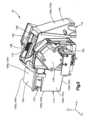
図1および図2を参照すると、生体試料および試薬を含んでいる診断消耗品ホルダ162を加熱し、加熱された生体試料の特性を測定するように構成された生体試料分析装置10が示してある。生体試料分析装置10は、生体試料の目標温度を上回る高温度を加えるように分析装置の少なくとも1つのヒータを設定することによって、消耗品ホルダ162の加熱を加速するように構成することができる。生体試料分析装置10は、生体試料分析装置10の様々な構成要素を収容するように構成されたハウジング14を含むことができる。このハウジング14は、少なくとも1つの外側壁18を含むことができる。この少なくとも1つの外側壁は、外側表面と、外側表面の反対側の内側表面とを有する。少なくとも1つの外側壁18の内側表面など、少なくとも1つの外側壁18は、生体試料を加熱しその特性を測定するための様々な構成要素を収容するように構成された、ハウジング14の内部空洞34を画成している。 1 and 2, a
ハウジング14は、第1の方向D1に沿って互いに離間している第1の端部14aと第2の端部14bとを有することができる。ハウジング14は、第1の方向D1に対して垂直な第2の方向D2に沿って互いに離間している第1の側部14cと第2の側部14dとを有することができる。ハウジング14は、第1の方向D1と第2の方向D2との両方に対して垂直な第3の方向D3に沿って互いに離間している上側端部14eと下側端部14fとを画成することができる。内部空洞34は、第1の端部14aと第2の端部14bとの間、第1の側部14cと第2の側部14dとの間、かつ上側端部14eと下側端部14fとの間に画成することができる。The
少なくとも1つの外側壁18は、複数の外側壁を画成することができる。例えば、少なくとも1つの外側壁18は、第1の端部14aに第1の壁18aを含むことができる。少なくとも1つの外側壁18は、第2の端部14bに第2の端壁18bを含むことができる。少なくとも1つの外側壁18は、第1の側部14cに第1の側壁18cを含むことができる。少なくとも1つの外側壁18は、第2の側部14dに第2の側壁18dを含むことができる。少なくとも1つの外側壁18は、上側端部14eに上側壁18eを含むことができる。少なくとも1つの外側壁18は、下側端部14fに下側壁18fを含むことができる。ハウジング14は、図示してある形状以外の形状を含め、中に空洞を画成する任意の好適な形状を有してよいことが理解されよう。したがって、少なくとも1つの外側壁18は、(例えば、ハウジング14が球形状を有する場合に)わずか1つの壁を含んでもよいし、または2つ以上の壁を含んでもよく、これらの壁は、図示してある形状以外の形状を有してもよい。 The at least one
少なくとも1つの外側壁18は、外側壁18を通って延びている開口部22を画成している。この開口部22は、空洞34に対して開口しており、それによりこの開口部22は、消耗品ホルダ162を受けて空洞34に入れるように構成されている。開口部22は、上側壁18e内など、ハウジング14の上側端部14e内に延びていてよい。しかし、代替的な実施形態では、開口部22は、端部14a、端部14b、側部14c、側部14d、および端部14eのうちの1つまたはそれ以上の中に延びていてもよいことが理解されよう。 At least one
生体試料分析装置10は、ハウジング14に対して可動に連結されたドア26を含むことができる。このドア26は、熱が開口部22を通って生体試料分析装置10から逃げないように、開口部22を選択的に覆うように構成することができる。開口部22を通して消耗品ホルダ162を受けるようにハウジング14が構成された開位置と、ドア26が開口部22を覆う閉位置との間で、ドア26は移動するように構成されている。閉位置において、ドア26は、消耗品ホルダ162が開口部22を通って生体試料分析装置10に挿入されることを防止するとともに、内部空洞34内にすでに配置された消耗品ホルダ162が生体試料分析装置10から取り出されることを防止する。生体試料分析装置10は、ドア26が開位置にあるか閉位置にあるかを検出するように構成されたドアセンサ30を含むことができる。このドアセンサ30は、例えば、ドアが開いているときもしくは閉じているときを検出することができるリレースイッチまたは任意の他の好適なセンサとすることができる。
ドアセンサ30は、コントローラ46と信号通信することができる。PIDコントローラとすることができるコントローラ46は、本明細書に記載の生体試料分析装置10の様々な動作を監視および制御するためのソフトウェアアプリケーションをホストするように構成された任意の好適なコンピューティングデバイスを含むことができる。コントローラ46は、任意の適切なコンピューティングデバイスを含むことができ、その例として、プロセッサ、デスクトップコンピューティングデバイス、サーバコンピューティングデバイス、またはポータブルコンピューティングデバイス、例えばラップトップ、タブレット、もしくはスマートフォンが挙げられることが理解されよう。コントローラ46は、物理的にハウジングに取り付けられるか、ハウジング14内に配置されるか、またはハウジング14に対して遠隔で、場合によりハウジング14から一定の距離で離間していることが可能である。
コントローラ46は、メモリ50を含むことができる。メモリ50は、揮発性(何らかの種類のRAMなど)であるか、不揮発性(ROM、フラッシュメモリなど)であるか、これらの組合せとすることができる。コントローラ46は、付加的なストレージ(例えば、取外し可能なストレージおよび/または取外し不可能なストレージ)を含むことができ、この付加的なストレージは、テープ、フラッシュメモリ、スマートカード、CD-ROM、デジタル多用途ディスク(DVD)、または他の光学的ストレージ、磁気テープ、磁気ディスクストレージ、または他の磁気的ストレージデバイス、ユニバーサルシリアルバス(USB)互換性メモリ、または情報を記憶するために使用可能で、コントローラ46によるアクセスが可能な任意の他の媒体を含むが、これらに限定されない。
コントローラ46は、場合により、ヒューマンマシンインターフェース(HMI)デバイス54を含むことができる。HMIデバイス54は、例えばボタン、ソフトキー、マウス、音声作動制御部、タッチスクリーン、コントローラ46の動き、視覚的合図(例えば、コントローラ46のカメラの前で手を動かすこと)などを介して、コントローラ46を制御する機能を実現する入力を含むことができる。HMIデバイス54は、生体試料分析装置10の様々な構成要素に関する視覚的情報を含む出力を、グラフィカルユーザインターフェースを介して提供することができる。他の出力は、(例えば、スピーカを介した)聴覚的情報、(例えば、振動機構を介した)機械的情報、またはこれらの組合せを含むことができる。様々な構成において、HMIデバイス54は、ディスプレイ、タッチスクリーン、キーボード、マウス、動き検出器、スピーカ、マイク、カメラ、またはこれらの組合せを含むことができる。HMIデバイス54は、例えば指紋情報、網膜情報、音声情報、および/または顔の特性情報などの生体認証情報を入力するための任意の好適なデバイスを含んで、例えばコントローラ46にアクセスするために特定の生体認証情報を必要としてよい。
コントローラ46は、ドアセンサ30、および生体試料分析装置10の様々な他の構成要素と有線通信および/または無線通信することができ、これについては以下でさらに説明する。所定の時間量にわたってドア26が開位置にあることをドアセンサ30が検知した場合に、コントローラ46、および具体的にはHMIデバイス54は、警告を発するように構成することができる。一実施形態において、所定の時間量は、約15秒とすることができる。しかし、所定の時間量は、必要に応じて15秒より長くても短くてもよいことが企図される。場合により、ドア26を開位置にしておくことができる所定の時間量を、生体試料分析装置10の操作者が手動で選択および/または調整できるように、HMIデバイス54は、ユーザ入力を受け取るように構成することができる。消耗品ホルダ162がハウジング14内に配置された後、所定の時間量にわたってドア26が開位置に維持されたとき、コントローラ46は、意図された加熱動作を無効にし、HMIデバイス54を介して対応する警告を発してよい。
図2を参照すると、ハウジング14の少なくとも1つの外側壁18は、少なくとも1つの外側壁18を通って延びている空気取入れ口38を画成することができる。空気取入れ口38は、ハウジング14の外側から空気を受け取り、内部空洞34に入れるように構成されている。空気取入れ口38は、少なくとも1つの外側壁18のあたりで離間した複数の開口部など、少なくとも1つの外側壁18を通って延びている少なくとも1つの開口部によって画成することができる。空気取入れ口38は、外側壁18のうちの少なくとも1つの外側壁の第1の壁を通って延びていてよい。図2では、空気取入れ口38が、第2の端部18bに画成されており、特に第2の端壁18bによって画成されている。さらに、空気取入れ口38は、第2および第3の方向D2、D3に対して平行な平面、例えば実質的に垂直に配向された平面に、実質的に沿って配向されている。しかし、空気取入れ口38は、ハウジング14の任意の別の側部または端部に画成することができ、異なる平面または複数の平面に沿って配向することができることが理解されよう。Referring to FIG. 2, at least one
ハウジング14の少なくとも1つの外側壁18は、少なくとも1つの外側壁18を通って延びている空気排出口42を画成することができる。空気排出口42は、少なくとも1つの外側壁18のあたりで、空気取入れ口38から離間している。空気排出口42は、外側壁18のうちの少なくとも1つの外側壁の第2の壁を通って延びていてよい。第2の外側壁は、空気取入れ口38が延びている第1の外側壁とは異なっていてよい。いくつかの実施形態では、第2の外側壁は、第1の外側壁から角度方向にオフセットしていてよい。空気排出口42は、内部空洞34からハウジング14の外側の領域に空気を排出するように構成されている。空気取入れ口38と同様に、空気排出口42は、少なくとも1つの外側壁18のあたりで離間した複数の開口部など、少なくとも1つの外側壁18を通って延びている少なくとも1つの開口部によって画成することができる。図2では、空気排出口42は、ハウジング14の下側端部18fに画成されており、特に下側端部壁18fによって画成されている。さらに、空気排出口42は、第1および第2の方向D1、D2に対して平行な平面、例えば実質的に水平に配向された平面に、実質的に沿って配向されている。その結果、空気取入れ口38は、空気排出口42から角度方向にオフセットしていてよい。図示してある実施形態では、空気取入れ口38は、空気排出口42から約90度、角度方向にオフセットしている。しかし、空気取入れ口38および空気排出口42は、必要に応じて互いに別の形で配向することができる。空気排出口42は、ハウジング14の任意の別の側部または端部に画成することができ、異なる平面または複数の平面に沿って配向することができることが理解されよう。At least one
空気取入れ口38は、受け取った空気を、取入れ方向DIに沿って内部空洞34に提供するように構成することができる。空気排出口42は、排出方向DEに沿って空洞34から空気を受け取り、その空気を空洞34から排出するように構成することができる。取入れ方向DIは、排出方向DEから角度方向にオフセットしていてよい。一例では、取入れ方向DIは、排出方向DEに対して実質的に垂直であってよい。代替的な実施形態では、取入れ方向DIと排出方向DEとは、互いに対して実質的に平行であってよい。いくつか実施形態において、空気取入れ口38は、取入れ方向DIに沿って空気を受け取ってよい。代替的または付加的に、いくつか実施形態において、空気排出口42は排出方向DEに沿って空気を排出してよい。しかし、代替的な実施形態では、空気取入れ口38に空気が受け入れられるとき、または空気排出口42から空気が排出されるときに、その空気の軌道を変更するルーバを、空気取入れ口38および空気排出口42のうちの少なくとも1つが含んでよいことが理解されよう。
図3を見ると、生体試料分析装置10は、ハウジング14の内部空洞34内に配置されたプレナム100を含んでいる。プレナム100は、内側プレナム表面と、内側表面の反対側の外側プレナム表面とを有する少なくとも1つのプレナム壁104を含むことができる。少なくとも1つのプレナム壁104の内側表面など、少なくとも1つのプレナム壁104は、中に空気導管120を画成している。プレナム100は、第1の方向D1に沿って互いに離間している第1のプレナム端部100aと第2のプレナム端部100bとを有することができる。プレナム100は、第2の方向D2に沿って互いに離間している第1のプレナム側部100cと第2のプレナム側部100dとを有することができる。プレナム100は、第3の方向D3に沿って互いに離間している上側プレナム端部100eと下側プレナム端部100fとを画成することができる。空気導管120は、第1のプレナム端部100aと第2のプレナム端部100bとの間、第1のプレナム側部100cと第2のプレナム側部100dとの間、かつ上側プレナム端部100eと下側プレナム端部100fとの間に画成することができる。Looking at FIG. 3,
少なくとも1つのプレナム壁104は、複数のプレナム壁を含むことができる。例えば、少なくとも1つのプレナム壁104は、第1のプレナム端部100aに第1のプレナム端壁104aを含むことができる。少なくとも1つのプレナム壁104は、第2のプレナム端部100bに第2のプレナム端壁104bを含むことができる。少なくとも1つのプレナム壁104は、第1のプレナム側部100cに第1のプレナム側壁104cを含むことができる。少なくとも1つのプレナム壁104は、第2のプレナム側部100dに第4のプレナム壁104dを含むことができる。少なくとも1つのプレナム壁104は、上側プレナム端部100eに上側プレナム壁104eを含むことができる。少なくとも1つのプレナム壁100は、下側プレナム端部100fに下側プレナム壁104fを含むことができる。プレナム100は、図示してある形状以外の形状を含め、任意の好適な形状を有してよいことが理解されよう。したがって、少なくとも1つの外側プレナム壁104は、わずか1つの壁を含んでもよいし、または2つ以上の壁を含んでもよく、これらの壁は、図示してある形状以外の形状を有してもよい。 At least one
少なくとも1つのプレナム壁104は、プレナム壁104を通って延びている開口部108を画成することができる。この開口部108は、空気導管120に対して開口しており、それによりこの開口部108は、消耗品ホルダ162を受けて空気導管120に入れるように構成されている。開口部108は、ハウジング14の開口部22の下に位置合わせされており、それによりハウジング14の開口部22から開口部108を通って空気導管120に入る真っ直ぐな経路が画成される。開口部108は、上側プレナム壁104e内など、プレナム100の上側端部100e内に延びていてよい。しかし、代替的な実施形態では、開口部108は、端部100a、端部100b、側部100c、側部100d、および端部100eのうちの1つまたはそれ以上の中に延びていてよいことが理解されよう。 At least one
プレナム100は、少なくとも1つのプレナム壁104を通って延びているプレナム取入れ口112を画成している。このプレナム取入れ口112は、ハウジング14の空気取入れ口38から空気を受け取り、プレナム100に入れるように構成されている。プレナム取入れ口112は、空気取入れ口38に隣接して配置され、それと流体連通しており、それにより空気取入れ口38で受け取られた空気は、プレナム取入れ口112に受け入れられる。プレナム取入れ口112は、少なくとも1つの開口部、または少なくとも1つのプレナム壁104のあたりで離間した複数の開口部によって画成することができる。図3では、プレナム取入れ口112は、第2のプレナム端部100bに画成されており、特に第2のプレナム端壁104bによって画成されている。さらに、プレナム取入れ口112は、第2および第3の方向D2、D3に対して平行な平面、例えば実質的に垂直に配向された平面に、実質的に沿って配向されている。しかし、プレナム取入れ口112は、プレナム100の任意の別の側部または端部に画成することができ、異なる平面または複数の平面に沿って配向することができることが理解されよう。
プレナム100は、少なくとも1つのプレナム壁104を通って延びているプレナム排出口116を画成している。空気導管120がプレナム排出口116からプレナム取入れ口112まで延びるように、プレナム排出口116は、少なくとも1つのプレナム壁104のあたりで、プレナム取入れ口112から離間している。プレナム排出口116は、プレナム100から空気を排出するように構成されている。プレナム排出口116は、空気排出口42に隣接して配置され、それと流体連通しており、それによりプレナム排出口116から排出された空気は、空気排出口42から排出される。プレナム取入れ口112と同様に、プレナム排出口116は、少なくとも1つの開口部、またはプレナム壁104のあたりで離間した複数の開口部によって画成することができる。図3では、プレナム排出口116は、下側プレナム端部100fに画成されており、特に下側プレナム端壁104fによって画成されている。さらに、プレナム排出口116は、第1および第2の方向D1、D2に対して平行な平面、例えば実質的に水平に配向された平面に、実質的に沿って配向されている。その結果、プレナム取入れ口112は、プレナム排出口116から角度方向にオフセットしていてよい。図示してある実施形態では、プレナム取入れ口112は、プレナム排出口116から90度だけ、角度方向にオフセットしている。しかし、プレナム取入れ口112とプレナム排出口116は、任意の他の好適な角度だけ、互いに角度方向にオフセットしていてよい。代替的な実施形態では、プレナム排出口112とプレナム取入れ口116は、互いに平行であってよい。プレナム排出口116は、プレナム100の任意の別の側部または端部に画成することができ、異なる平面または複数の平面に沿って配向することができることが理解されよう。
プレナム取入れ口112は、取入れ方向DIに沿って空気を受け取り、空気導管120に入れるように構成することができる。プレナム排出口116は、排出方向DEに沿って空気を排出するように構成することができる。上述したように、取入れ方向DIは、排出方向DEから角度方向にオフセットしていてよい。一例では、取入れ方向DIは、排出方向DEに対して実質的に垂直であってよい。代替的な実施形態では、取入れ方向DIと排出方向DEとは、互いに対して実質的に平行であってよい。動作中、生体試料分析装置10は、ハウジング14の空気取入れ口38を通して空気を受け取り、プレナム取入れ口112に通し、空気導管120に通し、プレナム排出口116に通して空気導管120から出し、空気排出口42に通してハウジング14から出すように構成されている。
ここで図4、図7、および図8を参照すると、生体試料分析装置10は、生体試料を含んでいる消耗品ホルダ162を支持するように構成されたレセプタクル154を含んでいる。レセプタクル154の少なくとも一部分は、プレナム100内に配置されている。レセプタクル154は、消耗品ホルダ162を受け取り、加熱および測定の動作中にそれを保持するように構成された開口端部を有することができる。レセプタクルは、実質的に矩形の形状を有してよい;しかし、レセプタクル154の形状は、受け取れられる消耗品ホルダの形状に応じて異なってよい。 4, 7 and 8,
図示してある実施形態では、レセプタクル154は、第1のホルダ端部158aと、第1の方向D1に沿って第1のホルダ端部158aの反対側にある第2のホルダ端部158bとを有している。レセプタクル154は、第1のホルダ端部158aから第2のホルダ端部158bまで延びている第1のホルダ側部158cと、第1のホルダ側部158cの反対側の、第1のホルダ端部158aから第2のホルダ端部158bまで延びている第2のホルダ側部158dとを有している。第1のホルダ側部158cおよび第2のホルダ側部158dは、第1および第2のヒータプレートとみなすことができるが、側部158cおよび158dは、消耗品ホルダ166を加熱するためのコイルなど、プレート以外の好適な構成であってもよい。また、レセプタクル154は、レセプタクル154の下側端部を画成し、第1のホルダ端部158aと第2のホルダ端部158bとの間、および第1のホルダ側部158cと第2のホルダ側部158dとの間のそれぞれに延びている底部ホルダ端部158eも含んでいる。レセプタクル154は、消耗品ホルダ162を加熱するために消耗品ホルダ162を受けるように構成された受け部領域170を画成することができ、ここで受け部領域170は、第1のホルダ端部158aと第2のホルダ端部158bとの間、第1のホルダ側部158cと第2のホルダ側部158dとの間、かつ底部ホルダ端部158eの上方に画成される。受け部領域170の寸法および形状は、受け部領域170内に配置される消耗品ホルダの種類および形状に応じて異なってよいが、図示してある実施形態では、受け部領域170は、第1の方向D1および第2の方向D2に沿って延びている平面において実質的に矩形の輪郭を有している。レセプタクル154は、アルミニウム、アルミニウム合金、銅などの熱伝導性の材料、または任意の他の好適な熱伝導性の材料から形成することができる。センサ174(図4および図6に示す)を、レセプタクル164内に配置することができ、レセプタクル164内に消耗品ホルダ162が挿入されているかどうかを検出するように構成することができる。カートリッジセンサ174は、消耗品ホルダの存在を検出することができるリレースイッチ、または任意の他の好適なセンサとすることができる。カートリッジセンサ174は、コントローラ46と信号通信して、消耗品ホルダ162がレセプタクル154に挿入されているかどうかをコントローラ46に通信することができる。In the illustrated embodiment, the
図5を見ると、レセプタクル154と少なくとも1つのプレナム壁104との間に少なくとも1つの空気間隙124が画成されるように、生体試料分析装置10は、プレナム100の空気導管120内でレセプタクル154の少なくとも一部分を支持することができる。空気導管120の一部分を含んだこの空気間隙124により、空気はレセプタクル154に沿って流れて、レセプタクル154を冷却することができる。空気間隙124は、少なくとも1つのプレナム壁104と、レセプタクル154の側部158a~158eの任意の組合せとの間に、画成することができる。例えば、空気間隙124は、レセプタクル154の第1のホルダ側部158cと第1のプレナム側壁104cとの間に画成された第1の空気間隙124aを含むことができる。空気間隙124は、追加として、または代替として、レセプタクル154の第2のホルダ側部158dと第2のプレナム側壁104dとの間に画成された第2の空気間隙124bを含むことができる。空気間隙124は、追加として、または代替として、底部ホルダ端部158eと下側プレナム壁104fとの間に画成することができる。 5,
図6を参照すると、空気を強制的に空気導管120に通すために、生体試料分析装置10はファン192を含むことができ、このファン192は、ハウジング14の空気取入れ口38から延びている経路Pに沿って空気を強制的に流し、プレナム100のプレナム取入れ口112に通し、空気間隙124に通し、プレナム排出口116に通し、ハウジング14の空気排出口42から出すように構成されている。具体的には、ファン192は、少なくとも1つの空気間隙124を通して、例えば第1の空気間隙124aおよび第2の空気間隙124bのうちの少なくとも1つを通して、レセプタクル154の第1の横方向側部158cおよび第2の横方向側部158dに沿って、空気を方向付けることができる。ファン192は、場合により、底部側部158eとプレナム壁104との間でレセプタクル154の下方に画成された空気間隙124の一部分にも空気を通して方向付ける。図示してある実施形態では、ファン192は、プレナム100のプレナム取入れ口112に配置されているが、ファン192の代替的な位置決めも企図される。例えば、ファン192は、代替として、プレナム排出口116に配置することもできる。ファン192は、コントローラ46と有線通信および/または無線通信することができ、それによりコントローラ46は、ファン192の動作を指示することができる。その結果、ファン192は、加熱動作において所定の間隔で、異なる速度間で選択的に遷移させることができ、これについては以下でさらに説明する。 6, to force air through
図4を再び参照すると、生体試料分析装置10は、ファン192に隣接して配置された温度センサ194も含むことができ、この温度センサ194は、ファン192によってプレナム100に吸い込まれる空気の周囲温度を検出するように構成されている。温度センサ194は、コントローラ46と有線通信および/または無線通信することができ、それによりコントローラ46は、温度センサ194によって検知された空気温度を監視することができる。強制的にプレナム100に入れられる空気の温度は、生体試料分析装置10の外側にある周囲温度の代表的温度とすることができ、これは消耗品ホルダ162の加熱動作に関する計算に有用なことがあり、これについては以下でさらに検討する。いくつか実施形態では、センサ194によって検知された空気温度が、分析装置の少なくとも1つのヒータからの熱出力によってゆがめられないようにするために、分析装置10は、空気流内の主プリント回路板(PCB)上に別の温度センサ(図示せず)を含むことができる。 Referring again to FIG. 4,
生体試料分析装置10は、ファン192の上流に配置されたフィルタ196(図4を参照)も含むことができ、このフィルタ196は、ファン192によってプレナム100に吸い込まれた空気から粒子を除去するように構成されている。時間の経過に伴い、フィルタ196がどんどん詰まってくることがあり、ファン192に提供される空気流が制限されてしまう程度まで、フィルタ196が詰まることがある。ファン192はレセプタクル154に少ない空気しか強制的に行き渡らせられないので、この低減した空気流は、レセプタクル154の冷却に悪影響を及ぼすことがある。フィルタ196の詰まりは、ヒータ186によって消費される瞬時電力と、基準電力消費量とを比較することにより、特定することができる。予想される消費量よりもヒータ186による電力消費量が低ければ、フィルタ196の詰まりを示唆している場合がある。次いでコントローラ46は、この情報を使用して、ファン192の速度を調節することができ、これについては以下でさらに説明する。
図7および図8に戻ると、生体試料分析装置10は、レセプタクル154を加熱するための少なくとも1つのヒータ186をさらに含むことができる。少なくとも1つのヒータ186は、レセプタクル154に直接または間接的に熱を加えてレセプタクル154を加熱することができる。次いでレセプタクル154は、レセプタクル154の受け部領域170内に消耗品ホルダ162が配置されたときに、消耗品ホルダ162に熱を加えることができる。少なくとも1つのヒータ186は、レセプタクル154の外側表面に取り付けることができる。例えば、少なくとも1つのヒータ186は、第1のホルダ端部158aおよび第2のホルダ側部158b、第1のホルダ側部158cおよび第2のホルダ側部158d、ならびに底部ホルダ端部158eのうちのいずれかの外側表面に取り付けることができる。少なくとも1つのヒータ186は、可撓性または剛性のプリント回路板(PCB)によって支持された導電性のコイル、例えばポリイミド可撓性ヒータ、またはレセプタクル154を加熱することができる任意の他の好適なヒータを含むことができる。少なくとも1つのヒータ186は、レセプタクル154の第1のホルダ側部158cに取り付けられた第1のヒータ186aと、第1のヒータ186aの反対側の、レセプタクル154の第2のホルダ側部158dに取り付けられた第2のヒータ186bとを含むことができる。しかし、ヒータ186は、必要に応じて2つより多いまたは少ないヒータを含むことができる。第1のヒータ186aおよび第2のヒータ186bを含む少なくとも1つのヒータ186は、コントローラ46と有線信号通信および/または無線信号通信することができ、それによりコントローラ46は、第1のヒータ186aおよび第2のヒータ186bの加熱プロファイルを制御および調整することが可能であり、これについては以下でさらに検討する。 Returning to FIGS. 7 and 8,
生体試料分析装置10は、レセプタクル154の温度を検出するように構成された少なくとも1つのヒータセンサ188を含むことができる。少なくとも1つのヒータセンサ188は、レセプタクル154に取り付けられた第1のヒータセンサ188aおよび第2のヒータセンサ188bを含むことができ、第1のヒータセンサ188aおよび第2のヒータセンサ188bのそれぞれは、レセプタクル154の瞬時温度を異なる位置で検出するように構成することができる。第1のヒータセンサ188aは、第1のヒータ186aに隣接してレセプタクル154の第1のホルダ側部158cに取り付けることができ、したがって第1のヒータ186aに隣接した位置において、レセプタクル154の温度を検出するように構成することができる。同様に、第2のヒータセンサ188bは、第2のヒータ186bに隣接してレセプタクル154の第2の横方向側部158dに取り付けることができ、したがって第2のヒータ186bに隣接した位置において、レセプタクル154の温度を検出するように構成することができる。第1のヒータセンサ188aおよび第2のヒータセンサ188bのそれぞれは、サーミスタなど、任意の好適な温度センサを含むことができる。2つのヒータセンサを具体的に説明しているが、生体試料分析装置10は、必要に応じて2つより多いまたは少ないヒータセンサを含むことができる。
消耗品ホルダ162内に配置されている生体分析物の温度は、直接測定されることは不可能である。その代わりに、分析物の温度は、レセプタクル154の温度に基づき間接的に制御することができる。したがって、生体試料分析装置10は、レセプタクル154に加えられる熱を制御するように構成されたフィードバックループを含むことができる。フィードバックループは、所定の間隔で(例えば、毎秒)継続的に更新することができる。フィードバックループは、コントローラ46と、少なくとも1つのヒータ186と、少なくとも1つのヒータセンサ188とを含む。少なくとも1つのヒータセンサ188は、レセプタクル154の検出(すなわち測定)温度をコントローラ46に提供するように構成することができる。コントローラ46は、検出温度および所望温度に基づき、温度誤差を特定するように構成することができる。次いでコントローラ46は、この温度誤差をゼロ誤差にするように、この温度誤差に基づき、少なくとも1つのヒータ186によって提供される熱量を制御することができる。以下で説明するように、所望温度は、目標温度、高温度、または設定値温度とすることができる。一例では、温度誤差は、所望温度と検出温度との差として特定することができる。別の例では、温度誤差は、所望温度と検出温度との割合に基づき特定することができる。一部のこのような例では、この割合から値1を引くことができる。 The temperature of the bioanalyte placed in
図3および図5を参照すると、ハウジング14内に生体分析センサ190を配置することができ、このセンサ190は、消耗品ホルダ162内に配置された生体試料の特性を測定するように構成されている。一実施形態では、フォトダイオードなどのセンサ190は光センサであるが、他の種類のセンサが企図される。分析装置10は、消耗品ホルダ162を通って、したがって生体試料を通ってセンサ190に至る光ビームを放出するように構成された光源191を含むことができる。センサ190は、生体試料のHbA1Cレベル、アルブミンとクレアチニンの比、ヘモグロビンレベル、凝集測定、または任意の他の所望の生体特性のうちの少なくとも1つを検出するように構成することができる。消耗品ホルダ162がレセプタクル154に挿入されたとき、センサ190が生体試料の特性を測定する前に、消耗品ホルダ162内に含まれた生体試料は、試薬との混合を必要とすることがある。これを達成するために、生体試料分析装置10は、ハウジング14内に取り付けられたモータ178を含むことができる。このモータ178は、プレナム100内でレセプタクル154を動かして、消耗品ホルダ162内の生体試料を撹拌するように構成することができる。モータ178は軸182を含むことができ、この軸182は、モータ178からプレナム100を通って延びて、モータ178の反対側のレセプタクル154に動作可能に接続されている。これにより、モータ178は、プレナム100の外側でハウジング14内に配置されることが可能になる。モータ178は、軸182を介してレセプタクル154を振動させるか、回転させるか、他のやり方で撹拌するように構成することができる。 3 and 5, a
消耗品ホルダ162内の生体試料を混合するために、プレナム100は、プレナム100内でレセプタクル154の動きを可能にするように特に設計することができる。例えば、少なくとも1つのプレナム壁104の上側部分は、プレナム100とレセプタクル154との間にクリアランスを提供するように湾曲していてよく、こうしてプレナム100に対するレセプタクル154の自由な動きおよび/または回転を可能にしてよい。第1のプレナム壁104aおよび第2のプレナム壁104bを含む残りのプレナム壁104も、この動きに対応するために、レセプタクル154から十分に離間していてよい。また、プレナム壁104のこの設計により、プレナム100は、レセプタクル154に沿った空気間隙124を通して空気を案内することができる。レセプタクル154のそれぞれの側部に沿って空気間隙124を画成することにより、プレナム100は、レセプタクル154からの熱が空気に伝わるレセプタクル154上の表面領域を提供する。
ここで図9および図12を参照しながら、生体試料分析装置を動作させる方法200を説明する。この方法200は、生体試料分析装置10の少なくとも1つのヒータ186の始動に対応したステップ202で開始することができる。始動したとき、コントローラ46は、レセプタクル154を高温度ETまで加熱するようヒータ186を制御する。図12に示してあるように、レセプタクル154は、開始時間t0において周囲温度ATであってよい。ステップ202において、ヒータ186は、開始時間t0における周囲温度ATから第1の時間t1における高温度ETまで、レセプタクル154を加熱する。このとき、コントローラ46は、周囲温度ATおよび目標温度TTに基づき、高温度ETを特定することができる。高温度ETはメモリ50に記憶することができ、コントローラ46は、メモリ50に記憶された高温度ETの1つまたはそれ以上の所定値から、周囲温度ATおよび目標温度TTに基づき、高温度ETを検索することができる。代替として、コントローラ46は、高温度ETを計算することができる。特定の加熱動作のための高温度ETは、式(1)により特定することができる:
ET=高温度
TT=目標温度
AT=周囲温度
SF=初期傾斜係数9 and 12, a
ET = high temperature TT = target temperature AT = ambient temperature SF = initial slope factor
式(1)において、目標温度TTは、生体試料の特定の特性を測定するために、消耗品ホルダ162内の生体試料を加熱すべき温度を表している。したがって、目標温度TTは、測定される特定の特性に基づき異なることになる。例えば、測定される特性がヘモグロビンの場合、HbA1cレベルについて、目標温度TTはセ氏34°、標準偏差セ氏+/-0.4°とすることができる。測定される特性が凝集の場合、HbA1cレベルについて、目標温度TTはセ氏34°、標準偏差セ氏+/-0.2°とすることができる。測定される特性が、アルブミンとクレアチニンの比である場合、目標温度TTはセ氏36°、標準偏差セ氏+/-0.4°とすることができる。しかし、他の目標温度が企図される。高温度ETは、TTより高い温度からセ氏約50°までの範囲であってよいが、この範囲外の高温度も企図される。周囲温度ATは、先に説明したように、ファン192に隣接した温度センサ194によって測定される生体試料分析装置10の外側の周囲環境の温度を表す。生体試料分析装置10がその中にある周囲温度ATは、セ氏約15°~セ氏約32°の範囲とすることができるが、他の周囲温度が企図される。初期傾斜係数は、システムに加えることが必要なエネルギー量を調整する定数である。高温度ETが加えられる時間量が増大される場合には、傾斜係数が増大される。この計算は、消耗品ホルダ162およびヒータプレートが固定質量を有することを前提としてよい。したがって、曲線下面積の合計(すなわち、総エネルギー)が、1つの生体試料の分析から次の生体試料の分析まで実質的に同じのまま保たれるように、傾斜係数を選択することができる。 In equation (1), target temperature TT represents the temperature to which the biological sample in
ステップ202の間、フィードバックループを使用して、レセプタクル154を高温度ETに上げることができ(時間t0から時間t1)、次いでその後、レセプタクル154を高温度ETに維持することができる(時間t1から時間t2)。このフィードバックループは、少なくとも1つのヒータ186によってレセプタクル154に加えられる熱を制御するために、上述したように継続的に更新することができる。この場合、高温度ETは所望温度として使用されて、温度誤差が特定される。During
消耗品ホルダ162がレセプタクル154内に配置されたときに、消耗品ホルダ162を目標温度TTにするのに必要な時間量を短縮するために、ステップ202は、消耗品ホルダ162がレセプタクル154に挿入される前に実施することができる。ステップ206において、消耗品ホルダ162をレセプタクル154に挿入することができる。図12に示すように、好ましくは、消耗品ホルダ162は、時間t1と時間t2との間の挿入時間tiに挿入される。カートリッジセンサ174は、ステップ206において、レセプタクル154への消耗品ホルダ162の挿入を検出することができ、消耗品ホルダ162が挿入されたことをコントローラ46に通信することができる。ステップ202および206の間、コントローラ46は、第1の速度でファン192を動作させることができ、これについては以下でさらに検討する。第1の速度は、ゼロまたは相対的に低速であってよく、したがって第1の速度のとき、ファンはオフであってもよいし、ゆっくり動いていてもよい。To reduce the amount of time required to bring the
ステップ210において、コントローラ46は、ハウジング14のドア26が所定の期間開放されたままになっているかどうかを特定することができる。消耗品ホルダ162がレセプタクル154に挿入された後、一定の時間量にわたってドア26が開放されたままである場合には、不明な量の熱が、生体試料分析装置10から開口部22を通って逃げる可能性がある。その結果、コントローラは、レセプタクル154を目標温度TTにするのに必要な熱量を特定することが困難になる恐れがある。一実施形態において、所定の期間は、約15秒とすることができるが、この期間は異なってもよい。さらに、所定の期間は、HMIデバイス54に入力を提供することにより、生体試料分析装置の操作者が手動で選択することができる。ドア26が所定の期間より長く開放されている場合には、ステップ214においてHMIデバイス54は、分析が失敗したことを操作者に知らせる警告を発してよい。さらにコントローラ46は、現在の加熱操作を無効にすることができる。ドア26が所定の期間にわたって開放されない場合には、ドアセンサ30は、方法200全体を通して、ドア26が開位置にあるか閉位置にあるかを監視し続けることができる。 At
ステップ206において、未加熱の消耗品ホルダ162がレセプタクル154に挿入されると、(高温度ETまで加熱されている)レセプタクル154よりも消耗品ホルダ162の温度が低いことにより、レセプタクル154の温度が、測定可能なほど低下することがある。この温度低下は、温度誤差を増大させることになる。挿入後、フィードバックループが、上述したように継続的に更新されて、レセプタクル154が高温度ETで(時間t1から時間t2まで)加熱され、温度誤差をゼロにすることができる。この場合、温度誤差を特定するために使用される所望温度は、高温度ETである。少なくともいくつかの実施形態において、少なくとも1つのヒータ186は、1つの消耗品ホルダから次の消耗品ホルダに繰り返し可能な、制御された速度で、加熱を増大させることができる。At
ステップ218では、図12に示してある挿入時間tiから第2の時間t2に及ぶ第1の期間にわたり、レセプタクル154を高温度ETに維持するよう、コントローラ46はヒータ186に指示することができる。ステップ218の間、フィードバックループが継続的に更新されて、レセプタクル154を高温度ET(時間t1から時間t2)に維持することができる。さらに、ファン192は、オフか相対的に低速な第1の速度で動作することができる。消耗品ホルダ162がレセプタクル154内に配置されている間に、レセプタクル154を第1の期間にわたって高温度ETに維持することにより、消耗品ホルダ162内に配置された生体試料を、従来のヒータよりも速い速度で目標温度TTにすることが支援される。第1の期間FPは、メモリ50に記憶された所定の時間とすることができ、コントローラ46は、メモリ50に記憶された第1の期間FPの1つまたはそれ以上の所定値から、第1の期間FPを検索することができる。代替として、第1の期間FPは、操作者がHMIデバイス54に入力することができる。さらに代替として、コントローラ46が、第1の期間FPを計算することができる。第1の期間FPは、式(2)によって以下のように特定することができる:
FP=(DTB+AT)*SDM (2)
ここで:
FP=第1の期間
DTB=減衰時間基準
AT=周囲温度
SDM=減衰開始乗数At
FP=(DTB+AT)*SDM (2)
here:
FP = first period DTB = decay time reference AT = ambient temperature SDM = decay start multiplier
減衰時間基準DTBは、第1の期間FPを特定するために使用されるオフセット係数である。いくつかの例では、DTBは約475とすることができる。いくつか実施形態において、消耗品ホルダ162が低温であると特定されない場合には、第1の期間を固定してよく、これについては以下で検討する。減衰開始乗数SDMは、高温度ETにおいて消耗品ホルダ162が加熱される時間の長さを短縮するために使用される係数である。いくつか実施形態において、減衰開始乗数SDMは、約0.05とすることができる。これにより、消耗品ホルダ162が目標温度に到達する前に、高温度ETにおける加熱を停止することが確保される。周囲温度ATは、生体試料分析装置の外部環境の温度を表し、この外部環境の温度は、プレナム100に入る空気の温度を、温度センサ194を使用して測定することにより特定される。式(2)では、第1の期間FPが、周囲温度ATに基づき特定される。したがって、コントローラ46は、第1の期間FPを特定するときに、消耗品ホルダ162が周囲温度ATにあると仮定する。しかし、操作者が、低温の消耗品ホルダをレセプタクル154に挿入する可能性があるので、これは常に当てはまるわけではない。したがって、生体試料分析装置10は、低温の消耗品ホルダを検出するように構成することができ、これについては以下でさらに詳細に説明する。 The decay time reference DTB is the offset factor used to identify the first period FP. In some examples, the DTB may be approximately 475. In some embodiments, the first time period may be fixed if the
ステップ222において、コントローラ46は、第1の期間FPの終わりに温度減衰を実施するよう、生体試料分析装置10を制御することができ、ここでレセプタクル154の温度は、高温度ETから目標温度TTに下げられる。特に、コントローラ46は、消耗品ホルダ162が目標温度TTを超える前に消耗品ホルダ162に加えられる熱量を低減するよう、少なくとも1つのヒータ186に指示することができる。さらに、コントローラ46は、第1の速度より速い第2の速度でファン192を動作させて、消耗品ホルダ162に加えられる熱量の低減を支援することができる。一実施形態では、図12に示してある第2の時間t2から第3の時間t3に及ぶ第2の期間にわたり温度を高温度ETから目標温度TTに低下させるよう、コントローラ46はヒータ186に指示することができる。その結果、レセプタクル154の温度は、高温度ETから目標温度TTに低下することになる。図12に示してあるように、高温度ETから目標温度TTへの温度低下のパターンは線形とすることができるが、他の温度低下のパターンが企図される。第2の期間から第3の期間t3までのヒータ186の温度設定値は、以下の式(3)により計算することができる:
SP=瞬時温度設定値
ISP=初期温度設定値
FSP=最終温度設定値
ID=初期温度低下
TPID=PID時間
TSD=減衰開始時間At
SP = instantaneous temperature set value ISP = initial temperature set value FSP = final temperature set value ID = initial temperature drop TPID = PID time TSD = decay start time
初期温度設定値ISPは、時間t2における温度である(例えば、高温度ET)。最終温度設定値は、時間t3の温度である(例えば、目標温度TT)。初期温度低下IDは、減衰をより速く行えるようにするための、初期温度設定値からの初期低下である。一例では、この値は、約0.5度に設定することができる。PID時間は、コントローラ46によって維持されるときの時間である。減衰開始時間TSDは、ステップ222において温度減衰が開始される時間である。消耗品ホルダ162およびそれに含まれた生体試料が目標温度TTまで上昇する前に、高温度ETから目標温度TTまでヒータ186の温度、したがってレセプタクル154の温度を低下させることにより、生体試料分析装置10は、消耗品ホルダ162の温度を素早く上昇させながらも、目標温度TTより高くなりすぎないようにすることを確保することができる。The initial temperature setpoint ISP is the temperature at timet2 (eg, high temperature ET). The final temperature setpoint is the temperature at timet3 (eg, target temperature TT). The initial temperature drop ID is the initial drop from the initial temperature set point to allow faster decay. In one example, this value can be set at approximately 0.5 degrees. PID time is the time as maintained by the
ステップ226では、レセプタクル154の温度が目標温度TTまで低下し、消耗品ホルダ162が目標温度TTまで上昇した後に、コントローラ46は、レセプタクル154を目標温度TTに維持するようヒータ186に指示することができる。これは、図12において、第3の時間t3から第4の時間t4まで生じるものとして示してある。さらに、コントローラ46は、第1の速度で、または第2の速度より遅い別の速度で、ファン192を動作させて、レセプタクル154のさらなる冷却を制限することができる。レセプタクル154を目標温度TTに維持することにより、消耗品ホルダ162およびその中に含まれた生体試料を、生体試料の特性を測定するプロセス全体を通して目標温度TTに維持することができる。At
ステップ230において、コントローラ46は、消耗品ホルダ162の内容物を能動的に混合するようモータ178に指示する。このとき、モータ178は、軸182を回転させて、レセプタクル154を回転させるか、振動させるか、他のやり方で動かすことができ、このレセプタクル154が、受け部領域170内に含まれた消耗品ホルダ162にその動きを伝える。ステップ230は、ステップ222と同時に(すなわち、図12の第2の時間t2と第3の時間t3との間に)実施することができる。代替として、ステップ230は、ヒータ186がレセプタクル154を目標温度TTに維持している間に(すなわち、図12の第3の時間t3と第4の時間t4との間でステップ226と同時に)実施しても、ステップ222および226と同時に実施してもよい。At
生体試料が、特定の測定動作のために十分に混合され、消耗品ホルダ162が目標温度で安定化するのに十分な時間が経過すると、センサ190は、ステップ234において、生体試料の特性を測定することができる。先に述べたように、この特性は、例えば生体試料のHbA1Cレベル、生体試料中のクレアチニンに対するアルブミンの比、または他の好適な特性とすることができる。測定されると、測定された特性を、センサ190からコントローラ46に送信することができる。図12のグラフを参照すると、ステップ234は、第3の時間t3の後で、かつ第4の時間t4の前に、レセプタクル154が目標温度TTに維持されている間に、実施することができる。Once the biological sample is sufficiently mixed for a particular measurement operation and sufficient time has elapsed for
生体試料の特性の測定が完了すると、ステップ238において、操作者は、消耗品ホルダ162を生体試料分析装置10から取り外すことができる。これを達成するために、操作者は、ハウジング14のドア26を開放し、消耗品ホルダ162に接続されたハンドル166を把持することにより、消耗品ホルダ162を受け部領域170から手動で取り外すことができる。受け部領域170から消耗品ホルダ162の取外しが完了すると、ステップ242を実施することができ、このステップ242では、レセプタクル154を加熱して目標温度TTから高温度ETに戻すよう、コントローラ46がヒータ186に指示する。このステップは、別の消耗品ホルダ162がレセプタクル154に挿入されるときに備えて、受け部領域170を事前加熱するために実施される。図12に示してあるように、ステップ242は第4の時間t4で開始され、第5の時間t5まで継続され、この第5の時間t5は、レセプタクル154が再び高温度に到達する時間である。これにより、1つの消耗品ホルダ162に対する1回の加熱および測定の動作の終了時と、別の消耗品ホルダ162に対する、その後の加熱および測定の動作の開始時との間で、遅延を最小限に抑えることができる。一実施形態において、この遅延は、20秒以下とすることができるが、他の遅延が企図される。Once the measurement of the biological sample properties is complete, the operator may remove the
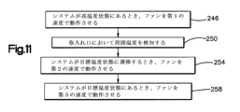
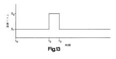
図9および図11を参照しながら、ファン192を動作させる方法をここで説明する。レセプタクル154が高温度ETにされ、その高温度ETで維持されているとき(図13における初期時間t0~第2の時間t2)、ステップ246において、コントローラ46は、第1の速度S1で動作するようファンに指示することができる。第1の速度は、アイドル速度または低速と呼ぶこともできる。第1の速度S1がゼロより大きい実施形態では、空気は第1の速度S1で、プレナム100の空気導管120に強制的に通され、レセプタクル154に沿って流される。ゼロより大きい第1の速度S1でファン192を動作させることは、プレナム100を通って流れる空気に過剰な熱を伝え、したがってハウジング14の空気排出口42から流出する空気とともに、過剰な熱の少なくとも一部を除去するように機能することができる。これにより、システム内の構成要素が過熱するのを防止することができ、空気の周囲温度を測定する、ファン192に隣接した温度センサ194が、ヒータ186により熱が生じた結果として偏った測定値を提示することを、防止することができる。A method of operating
ファン192が第1の速度S1で動作している間に、ステップ250において、温度センサ194は、空気取入れ口38を通って生体試料分析装置10に入る空気の周囲温度ATを検知することができ、周囲温度をコントローラ46に送信することができる。コントローラ46は、温度センサ194によって検知された周囲温度ATを、加熱プロファイルにおける様々な温度を特定するための上述した計算に使用することができる。ヒータ186が、レセプタクル154を高温度ETから目標温度TTに遷移させるとき、ステップ254において、コントローラ46は、図13に示してあるように、第1の速度S1から第2の速度S2に速度を上げるようファン192に指示することができる。図12において、これは第2の時間t2中に行われる。ファン192は、第2の時間t2から第3の時間t3までの第2の期間中に、第2の速度S2で動作することができる。第1の速度S1より速い第2の速度S2は、中速と呼ぶこともできる。こうしてファン192は、空気を第2の速度S2で、プレナム100の空気導管120に強制的に通し、レセプタクル154に沿って流す。ファン192が第2の速度S2で動作するとき、熱は、ファン192が第1の速度S1で動作しているときに普通なら生じる速度よりも素早く、レセプタクル154から、プレナム100に強制的に通される空気に伝えられる。このことは、消耗品ホルダ162が目標温度TTを超えて過熱するのを、さらに防止しやすくする。While the
第3の時間t3(図12に示す)に、レセプタクル154が目標温度TTに到達すると、ステップ258において、コントローラ46は、第2の速度S2から第3の速度S3に速度を落とすようファン192に指示することができる。第3の速度S3は、第2の速度S2より遅い。図13に示してあるように、例えば、第3の速度S3は、第1の速度S1に等しくてもよいし、または第2の速度S2を下回る別の速度であってもよい。ステップ258は、ヒータ186がレセプタクル154を目標温度TTに維持している間に実施することができる。ステップ246と同様に、ステップ258において第3の速度S3でファン192を動作させることは、プレナム100を通って流れる空気に過剰な熱を伝え、したがってハウジング14の空気排出口42から流出する空気とともに、過剰な熱の一部を除去するように機能することができる。At a third time t3 (shown in FIG. 12), when
上述したように、生体試料分析装置10は、フィルタ196を含むことができる。ヒータ186の電力消費量が予想より少ないことを、コントローラ46が検知した場合には、コントローラ46は、フィルタ196が詰まっている可能性があることを認識することができ、その後、第2の速度S2よりも速い高速で温度減衰中に動作するようファン192に指示することができる。ファン192を高速で動作させることにより、フィルタ196の詰まりの結果として空気プレナム100に入る空気量の低減を補償することができ、これにより、生体試料分析装置10は、加熱および検知の動作を通常どおりに実行し続けることができる。その結果、フィルタ196の稼働寿命を引き延ばすことができる。フィルタ196が詰まったときにファン192を高速に遷移させることに加えて、コントローラ46は、HMIデバイス54を介して生体試料分析装置10の操作者に対して、フィルタ196が詰まっており、交換が必要になる可能性があることを示す警告を発することもできる。As noted above,
図9および図10を参照すると、上述したようにいくつかの事例では、消耗品ホルダが周囲温度に到達する前に、操作者が低温の消耗品ホルダを生体試料分析装置10に挿入する可能性がある。生体試料分析装置10は、低温の消耗品ホルダを検出し、この低温の消耗品ホルダにさらに熱を加えて、分析のための目標温度まで低温の消耗品ホルダを加熱するように構成することができる。図10は、生体試料分析装置10を動作させる方法を示しており、この方法は、低温の消耗品ホルダを検出し、検出された低温の消耗品ホルダにさらに熱を加えて、分析のための目標温度まで低温の消耗品ホルダを加熱することを含む。図10の方法は、図9のステップ206の一部として実施可能である。一般に、試料分析装置10は、消耗品ホルダがレセプタクルに挿入されたときのレセプタクルの温度低下に基づき、消耗品ホルダが周囲温度より低いかどうかを検出するように構成することができる。この検出結果に基づき、分析装置10は、1)消耗品ホルダが周囲温度を下回らないことをコントローラが検出した場合には、消耗品ホルダを目標温度まで加熱するために、第1の熱エネルギー量を消耗品ホルダに加えるよう、少なくとも1つのヒータを制御し、2)消耗品ホルダが周囲温度を下回ることをコントローラが検出した場合には、消耗品ホルダを目標温度まで加熱するために、第1の熱エネルギー量よりも大きい第2の熱エネルギー量を消耗品ホルダに加えるよう、少なくとも1つのヒータを制御するように構成することができる。 9 and 10, as noted above, in some cases, an operator may insert a cold consumable holder into
上述したように、未加熱の(すなわち、低温または周囲温度の)消耗品ホルダ162がレセプタクル154に挿入されると、(ステップ202において高温度ETまで加熱されている)レセプタクル154よりも消耗品ホルダ162の温度が低いことにより、レセプタクル154の温度が、測定可能なほど低下することになる。この温度低下は、温度誤差(例えば、所望温度と少なくとも1つのヒータセンサ188によって検出された温度との差)を増大させることになる。低温の消耗品ホルダに関する温度低下は、周囲温度の消耗品ホルダに関する温度低下よりも素早い。したがって、温度誤差の増大は、周囲温度の消耗品ホルダに関するよりも、低温の消耗品ホルダに関するほうが著しい。しかし、低温の消耗品ホルダの挿入は、レセプタクル154の温度に影響を及ぼすのに時間がかかることがあり(例えば、5秒)、これを使用して、消耗品ホルダ162を低温の消耗品ホルダとして識別することができる。最終的には、フィードバックループがレセプタクル154を高温度ETに戻すときに、温度誤差がゼロに向かって戻される。 As noted above, when an unheated (i.e., cold or ambient temperature)
ステップ262~270において、コントローラ46は、消耗品ホルダが周囲温度ATを下回っているかどうか、したがって低温の消耗品ホルダであるかどうかを特定する。特に、ステップ262において、少なくとも1つのヒータセンサ188のそれぞれは、消耗品ホルダ162がレセプタクル154に挿入された後のレセプタクル154の初期温度を検出する。好ましくは、低温の消耗品ホルダの影響をレセプタクル154が受けられるように、この初期温度は、初期期間の後であるが、レセプタクル154が高温ETに戻ってしまう前に取得される。例えば、初期温度は、消耗品ホルダの挿入後、数秒で、例えば消耗品ホルダの挿入後、1秒、2秒、3秒、4秒、5秒、6秒、7秒、8秒、9秒、または10秒で測定することができる。好ましい実施形態では、初期温度は、消耗品ホルダの挿入後5秒で取得される。初期期間は、システムの熱時定数に基づいてよく、この熱時定数は、少なくとも1つのヒータセンサ188が温度変動に応答するのに必要とする時間である。ステップ266において、コントローラ46は、ステップ262において取得された初期温度に基づき、レセプタクル154の初期温度誤差を特定することができる。 In steps 262-270,
ステップ270において、コントローラ46は、初期温度誤差と所定の閾値とを比較することができる。初期温度誤差が所定の閾値内(例えば、誤差の計算方法に基づき、必要に応じてその上またはその下)にある場合には、コントローラ46は、消耗品ホルダ162が低温の消耗品ホルダではないと特定することができ、消耗品ホルダ162は、第1の期間FPに関して上述したように加熱することができる(ステップ274)。その一方で、温度誤差が所定の閾値(例えば、誤差の計算方法に基づき、必要に応じてその上またはその下)の外側にある場合には、コントローラ46は、消耗品ホルダ162が低温の消耗品ホルダであると特定することができ、消耗品ホルダ162を目標温度まで加熱するためにさらに熱を加えることが必要であると特定することができる(ステップ278)。一実施形態において、所定の閾値は、例えば、温度センサ194によって測定された周囲温度ATにおいて低温でない消耗品ホルダに関して予想される温度誤差、例えば(限定することなく)最大予想温度、に基づくものであってよい。初期温度誤差が、予想される温度誤差の特定の範囲の外側にある(例えば、予想される温度誤差の20パーセントより大きい)場合には、コントローラ46は、消耗品ホルダ162が低温の消耗品ホルダであると特定することができる。このような場合には、コントローラ46は、場合により、消耗品ホルダ162を目標温度まで加熱するのに必要な、延長される第1の期間の推定値を、初期温度誤差に基づき特定することができる。一例では、延長される第1の期間の推定値は、式(4)に示すように計算することができる:
EFPEは、延長される第1の期間の推定値であり;
FPは、上述した第1の期間であり;
TEiは、初期温度誤差であり;
TEEは、予測される温度誤差であり;
FPCは、定数である。At
EFPE is the estimate of the extended first period;
FP is the first period described above;
TEi is the initial temperature error;
TEE is the expected temperature error;
FPC is a constant.
ステップ276において、コントローラ46は、場合により、低温の消耗品ホルダが検出されたことを操作者に通知することができる。この通知は、HMIデバイス54を介して操作者に提供することができ、このHMIデバイス54は、この状況を操作者に示す警告を発することができる。いくつか実施形態において、コントローラ46は、操作者に対して追加の加熱時間の推定値を提供することができる。操作者は、必要に応じて、消耗品ホルダ162の相対的な低温状態に応答して、手動の措置を取ることを選択してよい。 At
ステップ278において、コントローラ46は、消耗品ホルダ162に伝えられる熱エネルギーを増大させることにより、レセプタクル154にさらに熱を加えることができる。熱エネルギー伝達をこのように増大することにより、温度誤差をゼロにしやすくすることができる。一実施形態において、伝えられる熱エネルギーは、ヒータ186に提供される電力を増大することによって、増大させることができ、それにより、ヒータ186はその温度を上昇させることができる。しかし、そのような実施形態では、少なくとも1つのヒータ186は、著しく増大したワット数を必要とすることがあり、これは加熱システムのコストと精度に悪影響を及ぼすことがある。代替的な実施形態では、コントローラ46は、レセプタクル154を高温度に維持する第1の期間を延長することができる。例えば、この延長は、温度誤差が所定の範囲からどれくらい外れているかに基づき、最大で約60秒とすることができる。 At
したがって、ステップ278において、コントローラ46は、消耗品ホルダ162を目標温度まで加熱するために使用されることになる延長される実際の第1の期間EFPAを特定することができる。さらに、コントローラ46は、上で検討した第1の期間FPの代わりに、延長される実際の第1の期間EFPAにわたって、レセプタクル154を高温度ETまで加熱することを、少なくとも1つのヒータ186に行わせることができる。(上記の、延長される推定の第1の期間EFPEに使用される)単一の温度誤差を使用するよりも、より高精度の特定を実現するために、延長される実際の第1の期間EFPAは、特定の消耗品ホルダ162に関して、少なくとも1つのヒータセンサ188によって経時的に検出された検出済み温度誤差のセットの合計に基づき、特定することができる。一例では、延長される実際の第1の期間は、式(5)に示すように計算することができる:
EFPAは、延長される実際の第1の期間であり;
FPは、上述した第1の期間であり;
ΣTESは、セット内の検出済み温度誤差の合計であり;
ΣTEEは、予想される温度誤差の合計である。Accordingly, at
EFPA is the actual first period extended;
FP is the first period described above;
ΣTES is the sum of the detected temperature errors in the set;
ΣTEE is the total expected temperature error.
式(5)において、検出済み温度誤差の合計ΣTESにおける第1の温度誤差は、消耗品ホルダがレセプタクル154に挿入されるおおよその時間に対応していてよいが、他の開始温度誤差を使用してもよい。合計ΣTESにおける最後の温度誤差は、ゼロにされていない(すなわち、レセプタクル154が高温度ETに到達する前の)温度誤差に対応している。一実施形態において、セット内の最後の温度誤差は、検出済み最大温度誤差の特定のパーセンテージ内にある温度誤差に対応してよいが、他の終了温度誤差を使用してもよい。例えば、特定のパーセンテージは約75パーセントとすることができ、ここでセット内の最後の温度誤差は、レセプタクル154の温度が上昇し、温度誤差が縮小している期間に対応することになる。コントローラ46は、特定の消耗品ホルダ162について経時的に蓄積された温度誤差から、検出済み最大温度誤差を識別し、検出済み最大温度誤差から、セットの最後の温度誤差を特定することができる。In equation (5), the first temperature error in the sum of detected temperature errors, ΣTES , may correspond to approximately the time the consumable holder is inserted into
本開示の生体試料分析装置は、従来の分析装置に勝る以下の利点のうちの1つもしくはそれ以上を含む1つまたはそれ以上の利点を提供することができる。例えば、本開示の生体試料分析装置は、挿入された消耗品ホルダが低温の消耗品ホルダであることを検出し、低温の消耗品ホルダの加熱を調整して所望の目標温度の消耗品ホルダにすることができるが、従来の分析装置は、低温の消耗品ホルダについて補償を行うことができない。消耗品ホルダが目標温度まで適切に加熱されていないことに起因して生じることがある試料分析結果の偏りまたは誤差を、これにより低減することができる。別の例として、本開示の生体試料分析装置は、所与の質量を有する消耗品ホルダを、比較可能な従来の分析装置よりも素早く目標温度まで加熱可能であってよい。これにより、測定結果の待機時間を短縮することができ、別々の消耗品ホルダの生体分析間の待機時間を短縮することができる。さらに別の例として、本開示の生体試料分析装置は、プレナムを通ってヒータに行き渡る集中的な空気流に起因して、比較可能な従来の分析装置よりも素早くそのヒータを冷却可能であってよい。また、集中的な空気流により、本開示の分析装置は目標温度よりも高い温度で動作して、消耗品ホルダをより素早く加熱することもできる。 A biological sample analyzer of the present disclosure may provide one or more advantages over conventional analyzers, including one or more of the following advantages. For example, the biological sample analyzer of the present disclosure detects that the inserted consumable holder is a low temperature consumable holder and adjusts the heating of the low temperature consumable holder to achieve the desired target temperature of the consumable holder. However, conventional analyzers cannot compensate for cold consumable holders. This can reduce bias or error in sample analysis results that can result from the consumable holder not being properly heated to the target temperature. As another example, the biological sample analyzer of the present disclosure may be able to heat a consumable holder having a given mass to a target temperature more quickly than comparable conventional analyzers. This can reduce the waiting time for measurement results and can reduce the waiting time between bioanalyses of different consumable holders. As yet another example, the biological sample analyzer of the present disclosure can cool its heater more quickly than comparable conventional analyzers due to the concentrated air flow through the plenum to the heater. good. The concentrated airflow also allows the analyzer of the present disclosure to operate above the target temperature to heat the consumable holder more quickly.
本発明の様々な発明的な態様、概念、および構成は、例示的な実施形態と組み合わせて具体化されたものとして本明細書において説明および図示されているが、これらの様々な態様、概念、および構成は、個々に、または様々なその組合せおよび部分的組合せで、多数の代替的な実施形態において使用することができる。本明細書において明示的に除外されていない限り、そのようなあらゆる組合せおよび部分的組合せは、本発明の範囲内に含まれることが意図される。さらに、本発明の様々な態様、概念、および構成に関する様々代替的な実施形態、例えば代替的な材料、構造、構成、方法、回路、デバイスおよび構成要素、ソフトウェア、ハードウェア、制御論理、形状に関する代替形態、適合状態、および機能などが、本明細書に記載されることがあるが、このような記載は、現在知られているか今後開発されるかに関わらず、利用可能な代替的な実施形態の完全なまたは網羅的なリストであることを意図していない。当業者であれば、そのような実施形態が本明細書において明示的に開示されていない場合でも、発明的な態様、概念、または構成のうちの1つまたはそれ以上を、本発明の範囲内に含まれる付加的な実施形態および使用法に容易に適合させることができる。さらに、本発明のいくつかの構成、概念、または態様が、好ましい構成または方法として本明細書に記載されている場合でも、そのような記載は、明示的に述べられていない限り、こうした構成が必須であったり必要であったりすることを示唆することが意図されるものではない。さらに、例示的または代表的な値および範囲は、本開示の理解を補助するために含まれるものとすることができる;しかし、そのような値および範囲は、限定する意味で解釈されるべきでなく、明示的に記載されている場合に限り、臨界値または臨界範囲であることが意図される。さらに、様々な態様、構成、および概念が、発明的であるものとして、または発明の一部を成すものとして、本明細書に明示的に識別されることがあるが、そのような識別が排他的であることは意図されておらず、むしろそのように明示的に識別されることなく、または特定の発明の一部として識別されることなく、本明細書において全面的に説明されている発明的な態様、概念、および構成が存在してもよく、その代わりに、本発明の範囲は、添付の特許請求の範囲、または関連するもしくは継続した明細書の特許請求の範囲に記載されている。例示的な方法またはプロセスの説明は、明示的な記載のない限り、あらゆる事例にすべての工程が必要なものとして含まれることに限定されず、必須または必要であるものと解釈されるように工程が提示される順序にも限定されない。 Although various inventive aspects, concepts, and configurations of the present invention are described and illustrated herein as being embodied in combination with exemplary embodiments, these various aspects, concepts, and configurations can be used in numerous alternative embodiments, individually or in various combinations and subcombinations thereof. All such combinations and subcombinations are intended to be included within the scope of the present invention, unless expressly excluded herein. Further, it relates to various alternative embodiments, such as alternative materials, structures, configurations, methods, circuits, devices and components, software, hardware, control logic, forms, etc., of various aspects, concepts, and configurations of the present invention. Although alternatives, adaptations, features, etc. may be described herein, such description is intended to cover alternative implementations available, whether now known or later developed. It is not intended to be an exhaustive or exhaustive list of forms. A person skilled in the art will recognize that one or more of the inventive aspects, concepts, or configurations fall within the scope of the invention, even if such embodiments are not explicitly disclosed herein. can be readily adapted for additional embodiments and uses included in the . Further, even if certain configurations, concepts, or aspects of the present invention are described herein as preferred configurations or methods, such description is not intended to imply that such configurations unless explicitly stated otherwise. It is not intended to imply that it is required or necessary. In addition, exemplary or representative values and ranges may be included to aid in understanding the present disclosure; however, such values and ranges should be construed in a limiting sense. Instead, critical values or critical ranges are intended only where explicitly stated. Moreover, although various aspects, configurations, and concepts may be expressly identified herein as inventive or forming part of the invention, such identification is exclusive. is not intended to be exhaustive, but rather the inventions that are fully described herein without being identified as such explicitly or as part of any particular invention. Certain aspects, concepts, and arrangements may exist, and instead the scope of the invention is indicated by the following claims or claims of any related or continuing specification. . Descriptions of exemplary methods or processes are not limited to including all steps as necessary in every instance, unless expressly stated otherwise. are not limited to the order in which the are presented.
本発明は、限られた数の実施形態を使用して本明細書に説明されているが、これらの特定の実施形態は、本明細書において別段に記載され特許請求されていない限り、本発明の範囲を限定することを意図するものではない。本明細書に記載の物品および方法の様々な要素の正確な構成および工程の順序は、限定するものとはみなされない。例えば、方法の工程は、一連の連続した参照符号および図におけるブロックの進行に関して説明されているが、方法は、必要に応じて特定の順序で実施することができる。 Although the present invention has been described herein using a limited number of embodiments, these specific embodiments are the same as the present invention unless otherwise described and claimed herein. is not intended to limit the scope of The precise configuration and order of steps of the various elements of the articles and methods described herein are not to be considered limiting. For example, although method steps are described in terms of a series of consecutive reference numerals and block progression in the figures, the method can be performed in a particular order, if desired.
別段の明示的な記載のない限り、それぞれの数値および範囲は、その値または範囲の前に「約」、「おおよそ」、または「実質的に」という用語が置かれているかのように、近似的であるものとして解釈されるべきである。「約」、「おおよそ」、および「実質的に」という用語は、別段の記載のない限り、特定値の15パーセント以内の範囲を表すものとして理解することができる。 Unless expressly stated otherwise, each numerical value and range is an approximation, as if the term "about," "approximately," or "substantially" preceded that value or range. should be construed as being subjective. The terms "about," "approximately," and "substantially" can be understood to denote ranges within 15 percent of the specified value, unless otherwise stated.
例示的実施形態
先の説明は、以下の例示的実施形態に関連して理解されよう。しかし、本明細書は、以下に記載の厳密な例示的実施形態に限定されないことを理解されたい。Exemplary Embodiments The preceding description should be understood in connection with the following exemplary embodiments. However, it should be understood that the specification is not limited to the precise exemplary embodiments set forth below.
例示的実施形態1:
生体試料分析装置であって:
少なくとも1つの外側壁を有するハウジングであって、少なくとも1つの外側壁は、中に内部空洞を画成し、少なくとも1つの外側壁を通って延びている空気取入れ口を画成し、少なくとも1つの外側壁を通って延びている空気排出口を画成する、ハウジングと;
内部空洞内に配置されたプレナムであって、空気取入れ口および空気排出口と流体連通している空気導管を中に画成する少なくとも1つのプレナム壁を有するプレナムと;
内部空洞内に配置されたレセプタクルであって、生体試料を含んでいる消耗品ホルダを支持するように構成されており、レセプタクルと少なくとも1つのプレナム壁との間に少なくとも1つの空気間隙が画成されるように、レセプタクルの少なくとも一部分が空気導管内に支持されている、レセプタクルと;
プレナムとともに配置された少なくとも1つのヒータであって、消耗品ホルダがレセプタクルによって支持されたときに消耗品ホルダを加熱するために、消耗品ホルダに熱を加えるように構成されたヒータと;
少なくとも1つのヒータを冷却するために、空気取入れ口から延びている経路に沿って空気を強制的に流し、少なくとも1つの空気間隙に通し、空気排出口に至らせるように構成されたファンと
を含む生体試料分析装置。Exemplary embodiment 1:
A biological sample analyzer comprising:
A housing having at least one outer wall, the at least one outer wall defining an interior cavity therein, defining an air intake extending through the at least one outer wall, and at least one a housing defining an air outlet extending through the outer wall;
a plenum disposed within the interior cavity, the plenum having at least one plenum wall defining an air conduit therein in fluid communication with the air intake and the air exhaust;
A receptacle disposed within the internal cavity and configured to support a consumable holder containing a biological sample, with at least one air gap defined between the receptacle and the at least one plenum wall. a receptacle, at least a portion of the receptacle supported within the air conduit, as in;
at least one heater disposed with the plenum, the heater configured to apply heat to the consumable holder to heat the consumable holder when the consumable holder is supported by the receptacle;
a fan configured to force air along a path extending from the air intake, through the at least one air gap, and to the air exhaust to cool the at least one heater; biological sample analyzer including;
例示的実施形態2:
プレナムは、少なくとも1つの空気間隙を通してレセプタクルに沿って空気を案内するように構成されている、例示的実施形態1に記載の生体試料分析装置。Exemplary embodiment 2:
The biological sample analyzer of exemplary embodiment 1, wherein the plenum is configured to guide air along the receptacle through the at least one air gap.
例示的実施形態3:
レセプタクルは、互いに離間している第1および第2のホルダ側部を画成しており、少なくとも1つのプレナム壁と、第1および第2のホルダ側部のうちの少なくとも1つのホルダ側部との間に、少なくとも1つの空気間隙が延びている、例示的実施形態1または2に記載の生体試料分析装置。Exemplary embodiment 3:
The receptacle defines first and second holder sides spaced apart from each other, with at least one plenum wall and at least one of the first and second holder sides. A biological sample analyzer according to exemplary embodiments 1 or 2, wherein at least one air gap extends between.
例示的実施形態4:
少なくとも1つの空気間隙は、少なくとも1つのプレナム壁と第1のホルダ側部との間に画成された第1の空気間隙と、少なくとも1つのプレナム壁と第2のホルダ側部との間の第2の空気間隙とを含む、例示的実施形態3に記載の生体試料分析装置。Exemplary embodiment 4:
The at least one air gap is a first air gap defined between the at least one plenum wall and the first holder side and between the at least one plenum wall and the second holder side. The biological sample analyzer of exemplary embodiment 3, comprising a second air gap.
例示的実施形態5:
少なくとも1つのプレナム壁は、互いに離間している第1および第2のプレナム壁を含んでおり、第1の空気間隙は、第1のプレナム壁とレセプタクルの第1のホルダ側部との間に画成されており、第2の空気間隙は、第2のプレナム壁とレセプタクルの第2のホルダ側部との間に画成されており、それによりプレナムは、レセプタクルの第1および第2のホルダ側部に沿って第1および第2の空気間隙を通して空気を案内するように構成されている、例示的実施形態3に記載の生体試料分析装置。Exemplary embodiment 5:
The at least one plenum wall includes first and second plenum walls spaced apart from each other, and a first air gap is between the first plenum wall and the first holder side of the receptacle. A second air gap is defined between the second plenum wall and the second holder side of the receptacle whereby the plenum extends between the first and second receptacles. A biological sample analyzer according to exemplary embodiment 3, configured to direct air along the holder sides through the first and second air gaps.
例示的実施形態6:
少なくとも1つのヒータは、レセプタクルの第1のホルダ側部に取り付けられた第1のヒータと、レセプタクルの第2のホルダ側部に取り付けられた第2のヒータとを含む、例示的実施形態3に記載の生体試料分析装置。Exemplary Embodiment 6:
4. According to example embodiment 3, wherein the at least one heater includes a first heater attached to the first holder side of the receptacle and a second heater attached to the second holder side of the receptacle. A biological sample analyzer as described.
例示的実施形態7:
第1のヒータに隣接してレセプタクルに取り付けられた第1のヒータセンサと;
第2のヒータに隣接してレセプタクルに取り付けられた第2のヒータセンサと
を含む、例示的実施形態6に記載の生体試料分析装置。Exemplary Embodiment 7:
a first heater sensor mounted in the receptacle adjacent to the first heater;
and a second heater sensor mounted in the receptacle adjacent to the second heater. The biological sample analyzer of exemplary embodiment 6.
例示的実施形態8:
消耗品ホルダ内の生体試料を撹拌するために、プレナム内でレセプタクルを動かすように構成されたモータを含む、例示的実施形態1~7のいずれか1つに記載の生体試料分析装置。Exemplary Embodiment 8:
The biological sample analyzer of any one of exemplary embodiments 1-7, comprising a motor configured to move the receptacle within the plenum to agitate the biological sample within the consumable holder.
例示的実施形態9:
プレナム壁を通って延び、動作可能にレセプタクルに接続された軸を、モータが含む、例示的実施形態8に記載の生体試料分析装置。Exemplary Embodiment 9:
The biological sample analyzer of exemplary embodiment 8, wherein the motor includes a shaft extending through the plenum wall and operably connected to the receptacle.
例示的実施形態10:
プレナムは、消耗品ホルダを中に通して受けるように構成された開口部を画成している、例示的実施形態1~9のいずれか1つに記載の生体試料分析装置。Exemplary Embodiment 10:
The biological sample analyzer of any one of exemplary embodiments 1-9, wherein the plenum defines an opening configured to receive a consumable holder therethrough.
例示的実施形態11:
ハウジングは、消耗品ホルダを中に通して受けるように構成されたハウジング開口部を画成しており、ハウジングは、ハウジング開口部の上に配置されたドアを含んでおり、ドアは、開口部を通して消耗品ホルダを受けてレセプタクルに入れるようにハウジングが構成されている開位置と、ハウジング開口部をドアが覆う閉位置との間で、動くように構成されている、例示的実施形態10に記載の生体試料分析装置。Exemplary Embodiment 11:
The housing defines a housing opening configured to receive the consumable holder therethrough, the housing including a door positioned over the housing opening, the door extending through the opening. In
例示的実施形態12:
少なくとも1つのヒータは、高温度をレセプタクルに加えるように構成されており、高温度は、レセプタクルの目標温度を上回っており、ファンは、少なくとも1つのヒータを目標温度まで冷却するために、消耗品ホルダが目標温度を超える前に少なくとも1つのヒータに強制的に空気を行き渡らせるように構成されている、例示的実施形態1~11のいずれか1つに記載の生体試料分析装置。Exemplary Embodiment 12:
The at least one heater is configured to apply an elevated temperature to the receptacle, the elevated temperature is above a target temperature of the receptacle, and the fan supplies the consumable to cool the at least one heater to the target temperature. 12. The biological sample analyzer of any one of exemplary embodiments 1-11, wherein the holder is configured to force air through the at least one heater before the target temperature is exceeded.
例示的実施形態13:
少なくとも1つの空気取入れ口は、少なくとも1つの外側壁の第1の壁を通って延びており、空気排出口は、第1の外側壁とは異なる外側壁のうちの少なくとも1つの外側壁の第2の壁を通って延びている、例示的実施形態1~12のいずれか1つに記載の生体試料分析装置。Exemplary Embodiment 13:
At least one air intake extends through a first wall of the at least one outer wall, and an air outlet extends through a first wall of the at least one outer wall that is different from the first outer wall. 13. A biological sample analyzer according to any one of exemplary embodiments 1-12, extending through two walls.
例示的実施形態14:
生体試料の特性を測定するように構成されたセンサを含む、例示的実施形態1~13のいずれか1つに記載の生体試料分析装置。Exemplary Embodiment 14:
14. A biological sample analyzer according to any one of exemplary embodiments 1-13, comprising a sensor configured to measure a property of the biological sample.
例示的実施形態15:
生体試料分析装置を動作させる方法であって:
生体試料分析装置のハウジングの内部空洞に支持されたレセプタクルに、生体試料を含んでいる消耗品ホルダを挿入する工程であって、レセプタクルの少なくとも一部分が、内部空洞に配置されたプレナムに配置されている、工程と;
消耗品ホルダを加熱するためにレセプタクルに熱を加えることを、プレナム内のレセプタクルによって支持された少なくとも1つのヒータに行わせる工程と;
レセプタクルを冷却するために、ハウジングによって画成された空気取入れ口から延びている経路に沿って空気を強制的に流し、レセプタクルとプレナムの少なくとも1つのプレナム壁との間に画成されたプレナム内の少なくとも1つの空気間隙に通し、ハウジングによって画成された空気排出口に至らせることをファンに行わせる工程と
を含む方法。Exemplary Embodiment 15:
A method of operating a biological sample analyzer comprising:
inserting a consumable holder containing a biological sample into a receptacle supported in an internal cavity of a housing of a biological sample analyzer, at least a portion of the receptacle being disposed in a plenum disposed in the internal cavity; there is a process;
causing at least one heater supported by the receptacle in the plenum to apply heat to the receptacle to heat the consumable holder;
In order to cool the receptacle, air is forced along a path extending from an air intake defined by the housing into a plenum defined between the receptacle and at least one plenum wall of the plenum. and causing a fan to pass through at least one air gap of and to an air outlet defined by the housing.
例示的実施形態16:
空気を強制的に流すことをファンに行わせる工程は、少なくとも1つのプレナム壁の第1の壁と、レセプタクルの第1のホルダ側部との間に画成された第1の空気間隙に空気を強制的に通し、少なくとも1つのプレナム壁の第2の壁と、第1のホルダ側部の反対側の、レセプタクルの第2のホルダ側部との間に画成された第2の空気間隙に空気を強制的に通すことを、ファンに行わせる工程を含む、例示的実施形態15に記載の方法。Exemplary Embodiment 16:
The step of forcing the air to flow through the fan includes forcing air into a first air gap defined between a first wall of the at least one plenum wall and a first holder side of the receptacle. and a second air gap defined between a second wall of the at least one plenum wall and a second holder side of the receptacle opposite the
例示的実施形態17:
消耗品ホルダ内の生体試料を撹拌するためにプレナム内でレセプタクルを動かすことを、生体試料分析装置のモータに行わせる工程を含む、例示的実施形態15または16に記載の方法。Exemplary Embodiment 17:
17. The method of
例示的実施形態18:
挿入する工程は、プレナムによって画成された開口部を通して消耗品ホルダを挿入する工程を含む、例示的実施形態15~17のいずれか1つに記載の方法。Exemplary Embodiment 18:
18. The method of any one of exemplary embodiments 15-17, wherein inserting includes inserting the consumable holder through an opening defined by the plenum.
例示的実施形態19:
生体試料分析装置に生体試料の特性を測定させる工程を含む、例示的実施形態15~18のいずれか1つに記載の方法。Exemplary embodiment 19:
19. The method of any one of exemplary embodiments 15-18, comprising causing a biological sample analyzer to measure a property of the biological sample.
例示的実施形態20:
熱を加えることを少なくとも1つのヒータに行わせる工程は、高温度で熱を加え、次いで高温度より低い目標温度で熱を加えることを、少なくとも1つのヒータに行わせる工程を含み;
空気を強制的に流すことをファンに行わせる工程は、熱が高温度で加えられているときには第1の速度で動作することをファンに行わせる工程と、少なくとも1つのヒータの温度が高温度から目標温度に低下しているときには、第1の速度より速い加速した速度で動作することをファンに行わせる工程とを含む、例示的実施形態15~19のいずれか1つに記載の方法。Exemplary embodiment 20:
causing the at least one heater to apply heat comprises applying heat at the elevated temperature and then causing the at least one heater to apply heat at a target temperature below the elevated temperature;
causing the fan to force the air flow comprises causing the fan to operate at a first speed when heat is being applied at the elevated temperature; and causing the fan to operate at an accelerated speed that is greater than the first speed when the temperature is dropping from the target temperature to the target temperature.
Claims (19)
Translated fromJapanese少なくとも1つの外側壁を有するハウジングであって、該少なくとも1つの外側壁は、中に内部空洞を画成し、少なくとも1つの外側壁を通って延びている空気取入れ口を画成し、少なくとも1つの外側壁を通って延びている空気排出口を画成する、ハウジングと;
内部空洞内に配置されたプレナムであって、空気取入れ口および空気排出口と流体連通している空気導管を中に画成する少なくとも1つのプレナム壁を有するプレナムと;
内部空洞内に配置されたレセプタクルであって、生体試料を含んでいる消耗品ホルダを支持するように構成されており、レセプタクルと少なくとも1つのプレナム壁との間に少なくとも1つの空気間隙が画成されるように、レセプタクルの少なくとも一部分が空気導管内に支持されている、レセプタクルと;
プレナムとともに配置された少なくとも1つのヒータであって、消耗品ホルダがレセプタクルによって支持されたときに消耗品ホルダを加熱するために、消耗品ホルダに熱を加えるように構成されたヒータと;
少なくとも1つのヒータを冷却するために、空気取入れ口から延びている経路に沿って空気を強制的に流し、少なくとも1つの空気間隙に通し、空気排出口に至らせるように構成されたファンと
を含み、
少なくとも1つのヒータは、高温度をレセプタクルに加えるように構成されており、高温度は、レセプタクルの目標温度を上回っており、ファンは、少なくとも1つのヒータを目標温度まで冷却するために、消耗品ホルダが目標温度を超える前に少なくとも1つのヒータに強制的に空気を行き渡らせるように構成されており、
少なくとも1つのヒータは、レセプタクルの外側表面に取り付けられている
前記生体試料分析装置。A biological sample analyzer comprising:
A housing having at least one outer wall defining an interior cavity therein and defining an air intake extending through the at least one outer wall; a housing defining an air outlet extending through the two outer walls;
a plenum disposed within the interior cavity, the plenum having at least one plenum wall defining an air conduit therein in fluid communication with the air intake and the air exhaust;
A receptacle disposed within the internal cavity and configured to support a consumable holder containing a biological sample, with at least one air gap defined between the receptacle and the at least one plenum wall. a receptacle, at least a portion of the receptacle supported within the air conduit, as in;
at least one heater disposed with the plenum, the heater configured to apply heat to the consumable holder to heat the consumable holder when the consumable holder is supported by the receptacle;
a fan configured to force air along a path extending from the air intake, through the at least one air gap, and to the air exhaust to cool the at least one heater;including
The at least one heater is configured to apply an elevated temperature to the receptacle, the elevated temperature is above a target temperature of the receptacle, and the fan supplies the consumable to cool the at least one heater to the target temperature. configured to force air through the at least one heater before the holder exceeds the target temperature;
At least one heater is attached to the outer surface of the receptacle
The biological sample analyzer.
第2のヒータに隣接してレセプタクルに取り付けられた第2のヒータセンサと
を含む、請求項6に記載の生体試料分析装置。a first heater sensor mounted in the receptacle adjacent to the first heater;
7. The biological sample analyzer of claim 6, including a second heater sensor mounted in the receptacle adjacent to the second heater.
生体試料分析装置のハウジングの内部空洞に支持されたレセプタクルに、生体試料を含んでいる消耗品ホルダを挿入する工程であって、レセプタクルの少なくとも一部分が、内部空洞に配置されたプレナムに配置されている、工程と;
消耗品ホルダを加熱するためにレセプタクルに熱を加えることを、プレナム内のレセプタクルによって支持され、レセプタクルの外側表面に取り付けられた少なくとも1つのヒータに行わせる工程と;
少なくとも1つのヒータを冷却するために、ハウジングによって画成された空気取入れ口から延びている経路に沿って空気を強制的に流し、レセプタクルとプレナムの少なくとも1つのプレナム壁との間に画成されたプレナム内の少なくとも1つの空気間隙に通し、ハウジングによって画成された空気排出口に至らせることをファンに行わせる工程と
を含む前記方法。A method of operating a biological sample analyzeraccording to any one of claims 1 to 13, comprising :
inserting a consumable holder containing a biological sample into a receptacle supported in an internal cavity of a housing of a biological sample analyzer, at least a portion of the receptacle being disposed in a plenum disposed in the internal cavity; there is a process;
causing at least one heater supported by the receptacle in the plenumand attached to the outer surface of the receptacle to apply heat to the receptacle to heat the consumable holder;
Air is forced along a path extending from an air intake defined by the housing to coolthe at least one heater and defined between the receptacle and at least one plenum wall of the plenum. causing the fan to pass through at least one air gap in the plenum and to an air outlet defined by the housing.
空気を強制的に流すことをファンに行わせる工程は、熱が高温度で加えられているときには第1の速度で動作することをファンに行わせる工程と、少なくとも1つのヒータの温度が高温度から目標温度に低下しているときには、第1の速度より速い加速した速度で動作することをファンに行わせる工程とを含む、請求項14に記載の方法。causing the at least one heater to apply heat comprises applying heat at the elevated temperature and then causing the at least one heater to apply heat at a target temperature below the elevated temperature;
causing the fan to force the air flow comprises causing the fan to operate at a first speed when heat is being applied at the elevated temperature; 15. The method of claim14 , comprising causing the fan to operate at an accelerated speed greater than the first speed when the temperature is dropping from to the target temperature.
Applications Claiming Priority (3)
| Application Number | Priority Date | Filing Date | Title |
|---|---|---|---|
| US201962822391P | 2019-03-22 | 2019-03-22 | |
| US62/822,391 | 2019-03-22 | ||
| PCT/US2020/022919WO2020197819A1 (en) | 2019-03-22 | 2020-03-16 | Biological sample analyzer with forced air convection plenum |
Publications (2)
| Publication Number | Publication Date |
|---|---|
| JP2022527249A JP2022527249A (en) | 2022-06-01 |
| JP7296477B2true JP7296477B2 (en) | 2023-06-22 |
Family
ID=72611110
Family Applications (1)
| Application Number | Title | Priority Date | Filing Date |
|---|---|---|---|
| JP2021556724AActiveJP7296477B2 (en) | 2019-03-22 | 2020-03-16 | Biological sample analyzer with forced air convection plenum |
Country Status (7)
| Country | Link |
|---|---|
| US (1) | US12292452B2 (en) |
| EP (1) | EP3942063A4 (en) |
| JP (1) | JP7296477B2 (en) |
| AU (2) | AU2020247732A1 (en) |
| CA (1) | CA3134430A1 (en) |
| MX (1) | MX2021011347A (en) |
| WO (1) | WO2020197819A1 (en) |
Citations (6)
| Publication number | Priority date | Publication date | Assignee | Title |
|---|---|---|---|---|
| JP2006125868A (en) | 2004-10-26 | 2006-05-18 | Arkray Inc | Cartridge for automatic measurement, and measuring method |
| JP2009282041A (en) | 1999-05-28 | 2009-12-03 | Cepheid | Cartridge for controlling chemical reaction |
| US20150140570A1 (en) | 2012-05-29 | 2015-05-21 | Arryx, Inc. | High-speed two-step incubation method and apparatus for in-vitro diagnostic testing |
| JP2016024054A (en) | 2014-07-21 | 2016-02-08 | 株式会社サカエ | Automatic analysis device |
| JP2017181202A (en) | 2016-03-29 | 2017-10-05 | ブラザー工業株式会社 | Inspection device |
| WO2018017769A1 (en) | 2016-07-21 | 2018-01-25 | Siemens Healthcare Diagnostics Inc. | Environmental control solution for clinical analyzer module |
Family Cites Families (53)
| Publication number | Priority date | Publication date | Assignee | Title |
|---|---|---|---|---|
| US3607099A (en)* | 1969-03-11 | 1971-09-21 | Medical Laboratory Automation | Prothrombin time measuring apparatus |
| US3616264A (en)* | 1969-06-30 | 1971-10-26 | Beckman Instruments Inc | Temperature-controlled discrete sample analyzer |
| US3677706A (en)* | 1970-02-24 | 1972-07-18 | Packard Instrument Co Inc | Reactor |
| US3971630A (en)* | 1975-10-07 | 1976-07-27 | Technicon Instruments Corporation | Apparatus and method for batch-type analysis of liquid samples |
| US4116775A (en)* | 1976-05-03 | 1978-09-26 | Mcdonnell Douglas Corporation | Machine and process for reading cards containing medical specimens |
| US4708886A (en) | 1985-02-27 | 1987-11-24 | Fisher Scientific Company | Analysis system |
| US4865986A (en) | 1988-10-06 | 1989-09-12 | Coy Corporation | Temperature control apparatus |
| US5455175A (en) | 1990-06-04 | 1995-10-03 | University Of Utah Research Foundation | Rapid thermal cycling device |
| US6787338B2 (en)* | 1990-06-04 | 2004-09-07 | The University Of Utah | Method for rapid thermal cycling of biological samples |
| US5646049A (en)* | 1992-03-27 | 1997-07-08 | Abbott Laboratories | Scheduling operation of an automated analytical system |
| US6156565A (en) | 1996-02-21 | 2000-12-05 | Biomerieux, Inc. | Incubation station for test sample cards |
| US6657169B2 (en) | 1999-07-30 | 2003-12-02 | Stratagene | Apparatus for thermally cycling samples of biological material with substantial temperature uniformity |
| US6423536B1 (en)* | 1999-08-02 | 2002-07-23 | Molecular Dynamics, Inc. | Low volume chemical and biochemical reaction system |
| EP1952886B1 (en) | 2001-07-16 | 2021-06-23 | BioFire Defense, LLC | Thermal cycling system and method of use |
| US7285425B2 (en)* | 2002-05-14 | 2007-10-23 | Siemens Medical Solutions Diagnostics | Assay test system for regulating temperature |
| US6730883B2 (en) | 2002-10-02 | 2004-05-04 | Stratagene | Flexible heating cover assembly for thermal cycling of samples of biological material |
| US7850912B2 (en) | 2003-05-14 | 2010-12-14 | Dako Denmark A/S | Method and apparatus for automated pre-treatment and processing of biological samples |
| US7338637B2 (en) | 2003-01-31 | 2008-03-04 | Hewlett-Packard Development Company, L.P. | Microfluidic device with thin-film electronic devices |
| EP1703284B1 (en) | 2003-12-25 | 2012-05-23 | ARKRAY, Inc. | Method of raising temperature of received object, and analyzing device |
| JP2007526479A (en) | 2004-03-02 | 2007-09-13 | ダコ デンマーク アクティーゼルスカブ | Reagent delivery system, dispensing device and container for biological staining apparatus |
| CN100565207C (en)* | 2004-10-01 | 2009-12-02 | 株式会社日立高新技术 | Chemical analysis apparatus |
| US20070064521A1 (en)* | 2005-09-22 | 2007-03-22 | Fluid Management Operations Llc | Apparatus for vibrating sample containers |
| US8124033B2 (en) | 2006-02-17 | 2012-02-28 | Agency, Science, Technology and Research | Apparatus for regulating the temperature of a biological and/or chemical sample and method of using the same |
| KR101307859B1 (en) | 2007-07-19 | 2013-09-12 | 삼성전자주식회사 | Bio-chemical analyzer and method for controlling inside temperatures thereof |
| JP2009109410A (en) | 2007-10-31 | 2009-05-21 | Nsk Ltd | Analyte liquid analyzer |
| CN102203605B (en)* | 2008-08-27 | 2014-07-23 | 生命技术公司 | Devices and methods for processing biological samples |
| US20100071443A1 (en) | 2008-09-25 | 2010-03-25 | Nathan Wrench | Temperature-controlled rheometer |
| CN102740976B (en)* | 2010-01-29 | 2016-04-20 | 精密公司 | Sample-Response Microfluidic Cartridges |
| JP2011191114A (en) | 2010-03-12 | 2011-09-29 | Sysmex Corp | Analyzer |
| JP5471900B2 (en) | 2010-07-01 | 2014-04-16 | 株式会社島津製作所 | Liquid chromatograph |
| JP5722001B2 (en) | 2010-11-10 | 2015-05-20 | 株式会社日立ハイテクノロジーズ | Genetic testing method and testing device |
| IT1403791B1 (en)* | 2010-12-30 | 2013-10-31 | St Microelectronics Srl | METHOD FOR CALIBRATING A TEMPERATURE SENSOR OF A CHEMICAL MICROREACTOR AND ANALYZER FOR BIOCHEMICAL ANALYSIS |
| JP5575043B2 (en) | 2011-03-31 | 2014-08-20 | 富士フイルム株式会社 | Analysis equipment |
| CA2835654A1 (en)* | 2011-06-01 | 2012-12-06 | Streck, Inc. | Rapid thermocycler system for rapid amplification of nucleic acids and related methods |
| EP2739747B1 (en)* | 2011-06-01 | 2016-08-17 | Streck Inc. | Rapid thermocycler system for rapid amplification of nucleic acids and related methods |
| US8885341B2 (en) | 2012-08-28 | 2014-11-11 | Motorola Mobility Llc | Compact front to back horizontal cooling for rack mounted chassis |
| MX375392B (en)* | 2013-01-18 | 2025-03-06 | Biomeme Incorporated | Analytic device |
| WO2014122924A1 (en)* | 2013-02-05 | 2014-08-14 | パナソニックヘルスケア株式会社 | Analysis device, genetic analysis method, analysis receptacle, and control method for fuzzy control |
| KR102127220B1 (en) | 2013-12-04 | 2020-06-26 | 삼성전자주식회사 | Bio material test device and controlling method thereof |
| EP3080577B1 (en)* | 2013-12-13 | 2021-07-28 | Ventana Medical Systems, Inc. | Thermal management in the context of automated histological processing of biological specimens and associated technology |
| US9804036B2 (en) | 2014-06-19 | 2017-10-31 | Infineon Technologies Ag | Temperature sensor calibration |
| US20160018426A1 (en)* | 2014-07-21 | 2016-01-21 | Sakae Co., Ltd. | Automatic analysis device |
| FR3024861B1 (en) | 2014-08-14 | 2018-03-23 | Psa Automobiles Sa. | WING STRUCTURE OF A MOTOR VEHICLE WITH MUDGUARD PROVIDED WITH A WATER EXHAUST ECOPE |
| JP2016191577A (en) | 2015-03-31 | 2016-11-10 | ブラザー工業株式会社 | Inspection device |
| EP3325161B1 (en) | 2015-07-23 | 2020-10-14 | Cepheid | Thermal control device and methods of use |
| US20200011857A1 (en) | 2017-03-16 | 2020-01-09 | Siemens Healthcare Diagnostics Inc. | System and method for thermal control of incubation system in diagnostic analyzer |
| EP3621738B1 (en) | 2017-05-09 | 2024-01-17 | Siemens Healthcare Diagnostics Inc. | Methods and apparatus for rapid heating of biological specimens |
| JP7120305B2 (en)* | 2018-06-18 | 2022-08-17 | 株式会社島津製作所 | Device with sample temperature control function |
| JP7031507B2 (en)* | 2018-06-18 | 2022-03-08 | 株式会社島津製作所 | Equipment with sample temperature control function |
| JPWO2020032226A1 (en)* | 2018-08-10 | 2021-08-10 | 株式会社Mirai Genomics | Analysis equipment |
| AU2020245293B2 (en)* | 2019-03-22 | 2022-02-24 | Siemens Healthcare Diagnostics Inc. | Biological sample analyzer with cold consumable detection |
| MX2021011348A (en)* | 2019-03-22 | 2021-10-13 | Siemens Healthcare Diagnostics Inc | Biological sample analyzer with accelerated thermal warming. |
| US11008627B2 (en)* | 2019-08-15 | 2021-05-18 | Talis Biomedical Corporation | Diagnostic system |
- 2020
- 2020-03-16JPJP2021556724Apatent/JP7296477B2/enactiveActive
- 2020-03-16CACA3134430Apatent/CA3134430A1/enactivePending
- 2020-03-16WOPCT/US2020/022919patent/WO2020197819A1/ennot_activeCeased
- 2020-03-16AUAU2020247732Apatent/AU2020247732A1/ennot_activeAbandoned
- 2020-03-16MXMX2021011347Apatent/MX2021011347A/enunknown
- 2020-03-16USUS17/593,490patent/US12292452B2/enactiveActive
- 2020-03-16EPEP20777663.4Apatent/EP3942063A4/enactivePending
- 2023
- 2023-12-01AUAU2023274201Apatent/AU2023274201B2/enactiveActive
Patent Citations (6)
| Publication number | Priority date | Publication date | Assignee | Title |
|---|---|---|---|---|
| JP2009282041A (en) | 1999-05-28 | 2009-12-03 | Cepheid | Cartridge for controlling chemical reaction |
| JP2006125868A (en) | 2004-10-26 | 2006-05-18 | Arkray Inc | Cartridge for automatic measurement, and measuring method |
| US20150140570A1 (en) | 2012-05-29 | 2015-05-21 | Arryx, Inc. | High-speed two-step incubation method and apparatus for in-vitro diagnostic testing |
| JP2016024054A (en) | 2014-07-21 | 2016-02-08 | 株式会社サカエ | Automatic analysis device |
| JP2017181202A (en) | 2016-03-29 | 2017-10-05 | ブラザー工業株式会社 | Inspection device |
| WO2018017769A1 (en) | 2016-07-21 | 2018-01-25 | Siemens Healthcare Diagnostics Inc. | Environmental control solution for clinical analyzer module |
Also Published As
| Publication number | Publication date |
|---|---|
| EP3942063A1 (en) | 2022-01-26 |
| EP3942063A4 (en) | 2022-05-04 |
| US20220170950A1 (en) | 2022-06-02 |
| WO2020197819A1 (en) | 2020-10-01 |
| AU2020247732A1 (en) | 2021-09-16 |
| AU2023274201B2 (en) | 2024-11-28 |
| AU2023274201A1 (en) | 2023-12-21 |
| CA3134430A1 (en) | 2020-10-01 |
| MX2021011347A (en) | 2021-10-13 |
| JP2022527249A (en) | 2022-06-01 |
| US12292452B2 (en) | 2025-05-06 |
Similar Documents
| Publication | Publication Date | Title |
|---|---|---|
| JP7296478B2 (en) | Biological sample analyzer that accelerates thermal heating | |
| JP7162149B2 (en) | Biological sample analyzer that detects low-temperature consumables | |
| KR20160111707A (en) | Cooking apparatus and controlling method thereof | |
| JPWO2019008727A1 (en) | Kneader control device, kneader control method, program | |
| EP2739747B1 (en) | Rapid thermocycler system for rapid amplification of nucleic acids and related methods | |
| CN109478077A (en) | Environmental Kuznets Curves solution for clinical analysers module | |
| JP3977141B2 (en) | Apparatus and method for controlling microwave oven | |
| JP7296477B2 (en) | Biological sample analyzer with forced air convection plenum | |
| CN110618223A (en) | Device with sample temperature adjusting function | |
| JP7573054B2 (en) | Biological sample analyzer with automatic thermal cooling adjustment for altitude | |
| KR101335940B1 (en) | Bio material test device and controlling method thereof | |
| JP2003177825A (en) | Overshoot prevention type temperature controller | |
| CN117629357A (en) | Thermogravimetric measuring device and setting method |
Legal Events
| Date | Code | Title | Description |
|---|---|---|---|
| A621 | Written request for application examination | Free format text:JAPANESE INTERMEDIATE CODE: A621 Effective date:20211215 | |
| A977 | Report on retrieval | Free format text:JAPANESE INTERMEDIATE CODE: A971007 Effective date:20221130 | |
| A131 | Notification of reasons for refusal | Free format text:JAPANESE INTERMEDIATE CODE: A131 Effective date:20221206 | |
| A521 | Request for written amendment filed | Free format text:JAPANESE INTERMEDIATE CODE: A523 Effective date:20230306 | |
| TRDD | Decision of grant or rejection written | ||
| A01 | Written decision to grant a patent or to grant a registration (utility model) | Free format text:JAPANESE INTERMEDIATE CODE: A01 Effective date:20230516 | |
| A61 | First payment of annual fees (during grant procedure) | Free format text:JAPANESE INTERMEDIATE CODE: A61 Effective date:20230612 | |
| R150 | Certificate of patent or registration of utility model | Ref document number:7296477 Country of ref document:JP Free format text:JAPANESE INTERMEDIATE CODE: R150 |