JP7293761B2 - Determining method for dialysis machine and circuit set - Google Patents
Determining method for dialysis machine and circuit setDownload PDFInfo
- Publication number
- JP7293761B2 JP7293761B2JP2019050273AJP2019050273AJP7293761B2JP 7293761 B2JP7293761 B2JP 7293761B2JP 2019050273 AJP2019050273 AJP 2019050273AJP 2019050273 AJP2019050273 AJP 2019050273AJP 7293761 B2JP7293761 B2JP 7293761B2
- Authority
- JP
- Japan
- Prior art keywords
- dialysate
- line
- circuit
- replacement fluid
- blood
- Prior art date
- Legal status (The legal status is an assumption and is not a legal conclusion. Google has not performed a legal analysis and makes no representation as to the accuracy of the status listed.)
- Active
Links
- 238000000502dialysisMethods0.000titleclaimsdescription65
- 238000000034methodMethods0.000titleclaimsdescription63
- 239000008280bloodSubstances0.000claimsdescription207
- 210000004369bloodAnatomy0.000claimsdescription207
- 239000012530fluidSubstances0.000claimsdescription172
- 230000037452primingEffects0.000claimsdescription58
- 239000007788liquidSubstances0.000claimsdescription52
- 230000005856abnormalityEffects0.000claimsdescription5
- XLYOFNOQVPJJNP-UHFFFAOYSA-NwaterSubstancesOXLYOFNOQVPJJNP-UHFFFAOYSA-N0.000description16
- 239000012528membraneSubstances0.000description13
- 239000012510hollow fiberSubstances0.000description12
- 238000010586diagramMethods0.000description8
- 238000000108ultra-filtrationMethods0.000description8
- 239000002699waste materialSubstances0.000description7
- 210000001367arteryAnatomy0.000description5
- 230000017531blood circulationEffects0.000description5
- 238000001914filtrationMethods0.000description5
- 210000003462veinAnatomy0.000description5
- 230000036772blood pressureEffects0.000description2
- 210000004204blood vesselAnatomy0.000description2
- 230000007423decreaseEffects0.000description2
- 230000018044dehydrationEffects0.000description2
- 238000006297dehydration reactionMethods0.000description2
- 238000001514detection methodMethods0.000description2
- 230000000694effectsEffects0.000description2
- 238000002637fluid replacement therapyMethods0.000description2
- 238000001631haemodialysisMethods0.000description2
- 230000000322hemodialysisEffects0.000description2
- 230000010365information processingEffects0.000description2
- 208000001647Renal InsufficiencyDiseases0.000description1
- 230000004308accommodationEffects0.000description1
- 230000001934delayEffects0.000description1
- 206010013663drug dependenceDiseases0.000description1
- 201000006370kidney failureDiseases0.000description1
- 238000005086pumpingMethods0.000description1
- 238000000746purificationMethods0.000description1
- 208000011117substance-related diseaseDiseases0.000description1
Images


Landscapes
- External Artificial Organs (AREA)
Description
Translated fromJapanese本発明は、透析装置及び該透析装置に用いられる回路セットの判定方法に関する。 The present invention relates to a dialysis machine and a method for determining circuit sets used in the dialysis machine.
血液透析や血液濾過透析等の治療に用いられる透析装置は、患者の血液を浄化する血液浄化器と、血液浄化器に接続され患者の血液を循環させるための血液回路と、血液浄化器に透析液を導入及び導出するための透析液回路と、補充液として透析液を血液回路に送液するための補充液ラインと、を含んで構成される回路セットを用いて血液透析を行う。また、透析装置に搭載される制御装置は、血液回路に設けられる血液ポンプや透析液回路に設けられる透析液ポンプ等の送液速度を制御して、プライミング工程、除水工程、補液工程、返血工程等の各種工程を自動で運転できるように構成されている(特許文献1参照)。
回路セットは、透析治療の種類によって補充液ラインの有無や血液浄化器の種類が異なり、医療従事者により透析治療前に各部品が接続されて組み立てられ、透析装置に取り付けられる。その後、回路セットの内部を洗浄して清浄化するプライミング工程が行われる。A dialysis machine used for treatment such as hemodialysis and hemodiafiltration consists of a blood purifier that purifies the patient's blood, a blood circuit that is connected to the blood purifier to circulate the patient's blood, and dialysis in the blood purifier. Hemodialysis is performed using a circuit set including a dialysate circuit for introducing and withdrawing a fluid and a replacement fluid line for sending the dialysate as a replacement fluid to the blood circuit. In addition, the control device mounted on the dialysis machine controls the liquid feeding speed of the blood pump provided in the blood circuit and the dialysate pump provided in the dialysate circuit to perform the priming process, the water removal process, the fluid replacement process, and the return process. It is configured so that various processes such as the blood process can be automatically operated (see Patent Document 1).
Depending on the type of dialysis treatment, the circuit set differs in the presence or absence of a replacement fluid line and the type of blood purifier. The circuit set is assembled by connecting each component before the dialysis treatment and attached to the dialysis machine. A priming step is then performed to wash and clean the interior of the circuit set.
自動で行われるプライミング工程では、血液浄化器の種類や補充液ラインの有無に応じて逆濾過透析液又は透析液がプライミング液として用いられる。
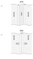
血液浄化器は中空糸型と積層型に分けられ、中空糸型のうち限外濾過率が高いものはプライミング可能な速度で透析液の逆濾過が可能であり、限外濾過率が低いものは、プライミング可能な速度で透析液を逆濾過することができない。また、図5に示すように積層型の血液浄化器は、透析膜と透析膜の間を血液が流れるように構成されており(図5(a)参照)、透析液側から圧力をかけると透析膜同士が密着するため(図5(b)参照)、逆濾過が困難な構造となっている。よって、限外濾過率の低い中空糸型及び積層型の血液浄化器は、プライミング方法として補充液ラインを介した透析液によるプライミングを行う必要がある。また、補充液ラインが接続された回路セットの場合は、補充液ラインのプライミングを行うため、血液浄化器の種類によらず補充液ラインを介した透析液によるプライミングを行う必要がある。In the automatically performed priming process, a backfiltration dialysate or a dialysate is used as the priming liquid depending on the type of blood purifier and the presence or absence of a replacement liquid line.
Blood purifiers are divided into hollow fiber types and laminated types. Of the hollow fiber types, those with a high ultrafiltration rate are capable of backfiltrating the dialysate at a rate that allows priming, while those with a low ultrafiltration rate are , unable to backfilter the dialysate at a primable rate. As shown in FIG. 5, the laminated blood purifier is configured such that blood flows between dialysis membranes (see FIG. 5(a)), and when pressure is applied from the dialysate side, Since the dialysis membranes are in close contact with each other (see FIG. 5(b)), the structure makes backfiltration difficult. Therefore, hollow-fiber type and laminated type blood purifiers with low ultrafiltration rates need to be primed with dialysate through a replenisher line as a priming method. In the case of a circuit set to which a replacement fluid line is connected, priming of the replacement fluid line is performed, so priming with dialysate via the replacement fluid line must be performed regardless of the type of blood purifier.
上述したように、プライミング工程では患者によって変わる回路セットの内容に応じて適切なプライミング方法を選ぶ必要があり、医療従事者は、プライミング工程開始時にプライミング方法の設定の確認や変更を行う必要がある。この設定は、透析装置において医療従事者が行う他、複数の透析装置を集中的に管理する透析システムにより行うこともできる。
しかしながら、設定ミスや設定変更の遅れにより、回路セットの内容に対応しないプライミング方法に設定されている場合があり、その場合、医療従事者に異常を報知して設定を修正する必要があり、プライミング工程を中断しなければならなかった。As described above, in the priming process, it is necessary to select an appropriate priming method according to the contents of the circuit set, which varies from patient to patient, and medical personnel must check and change the settings of the priming method at the start of the priming process. . This setting can be performed by medical personnel at the dialysis machine, or by a dialysis system that centrally manages a plurality of dialysis machines.
However, due to setting errors or delays in setting changes, there are cases in which a priming method that does not correspond to the contents of the circuit set is set. I had to stop the process.
従って、本発明は、回路セットの内容を判定可能な透析装置を提供することを目的とする。 SUMMARY OF THE INVENTION It is therefore an object of the present invention to provide a dialysis machine capable of determining the contents of a circuit set.
本発明は、血液浄化器が配置される血液回路と、前記血液浄化器に透析液を送液する透析液ポンプが配置される透析液回路と、前記血液回路に直接注入される透析液を取り出す補充液ポートと、一端が前記透析液回路に接続され他端が前記補充液ポートに接続され、前記透析液回路から前記血液回路に透析液を送液する補充液ポンプが配置される第1の補充液ラインと、前記補充液ポートと前記補充液ポンプとの間に配置されて、前記第1の補充液ラインの液圧を測定するための補充液圧センサと、一端が前記補充液ポートと接続され、他端が前記血液回路に接続される第2の補充液ラインの流路の開閉を行う補充液クランプと、前記補充液圧センサに接続されて前記第2の補充液ラインの有無を判定する第1の判定部を有し、前記透析液ポンプ、前記補充液ポンプ及び前記補充液クランプの動作を制御する制御装置と、を備える透析装置であって、前記制御装置は、前記補充液クランプを閉状態として所定量の透析液を送液するよう前記透析液ポンプ及び前記補充液ポンプを動作後に停止させた後、前記補充液クランプを開状態とするよう制御し、前記第1の判定部は、前記補充液クランプが閉状態から開状態とするように制御された後、前記第1の補充液ラインの液圧が下がる場合には前記第2の補充液ラインが接続されていると判定し、該第1の補充液ラインの液圧が一定の場合には前記第2の補充液ラインが接続されていないと判定する透析装置に関する。 The present invention comprises a blood circuit in which a blood purifier is arranged, a dialysate circuit in which a dialysate pump for sending dialysate to the blood purifier is arranged, and a dialysate that is directly injected into the blood circuit and is taken out. A first replacement fluid port and a replacement fluid pump having one end connected to the dialysate circuit and the other end connected to the replacement fluid port for pumping dialysate from the dialysate circuit to the blood circuit. a replenishment line, a replenishment pressure sensor disposed between the replenishment port and the replenishment pump for measuring fluid pressure in the first replenishment line, and one end connected to the replenishment port. a replacement fluid clamp for opening and closing the flow path of a second replacement fluid line connected at the other end to the blood circuit; A dialysis apparatus comprising a controller for controlling operations of the dialysate pump, the replenisher pump, and the replenisher clamp, wherein the controller includes a first determination unit that determines the replenisher After the dialysate pump and the replacement fluid pump are stopped after the clamp is closed so as to send a predetermined amount of dialysate, the replacement fluid clamp is controlled to be opened, and the first determination is performed. The section determines that the second replenisher line is connected when the liquid pressure in the first replenisher line drops after the replenisher clamp is controlled from the closed state to the open state. and determining that the second replenishment line is not connected when the fluid pressure in the first replenishment line is constant.
また、本発明は、血液浄化器が配置される血液回路と、前記血液浄化器に透析液を送液する透析液ポンプが配置される透析液回路と、前記透析液回路内の液圧を測定する透析液圧センサと、前記血液浄化器において所定の速度で逆濾過が可能であるか否かを判定する第2の判定部を有し、前記透析液ポンプの動作を制御する制御装置と、を備える透析装置であって、前記制御装置は、前記透析液ポンプを逆濾過方向に動作させ、前記第2の判定部は、前記透析液ポンプが逆濾過方向に動作後、所定の時間が経過したときに、前記透析液圧センサにより測定される前記透析液回路の液圧が所定の閾値以下である場合に、前記血液浄化器において前記所定の速度で逆濾過が可能であると判定し、該透析液回路の液圧が前記所定の閾値を超える場合に、前記血液浄化器において前記所定の速度で逆濾過が不可能であると判定する透析装置に関する。 Further, the present invention includes a blood circuit in which a blood purifier is arranged, a dialysate circuit in which a dialysate pump for sending dialysate to the blood purifier is arranged, and a liquid pressure in the dialysate circuit is measured. a dialysate pressure sensor that controls the operation of the dialysate pump; wherein the control device operates the dialysate pump in the backfiltration direction, and the second determination unit determines that a predetermined time has elapsed after the dialysate pump has been operated in the backfiltration direction determining that backfiltration is possible in the blood purifier at the predetermined speed when the liquid pressure in the dialysate circuit measured by the dialysate pressure sensor is equal to or less than a predetermined threshold; It relates to a dialysis apparatus that determines that backfiltration at the predetermined speed is impossible in the blood purifier when the hydraulic pressure of the dialysate circuit exceeds the predetermined threshold.
また、本発明は、血液浄化器が配置される血液回路と、前記血液浄化器に透析液を送液する透析液ポンプが配置される透析液回路と、前記透析液回路に配置され、該透析液回路内の液圧を測定する透析液圧センサと、前記血液回路に直接注入される透析液を取り出すための補充液ポートと、一端が前記透析液回路に接続され他端が前記補充液ポートに接続され、前記透析液回路から前記血液回路に透析液を送液する補充液ポンプが配置される第1の補充液ラインと、前記補充液ポートと前記補充液ポンプとの間に配置されて、前記第1の補充液ラインの液圧を測定するための補充液圧センサと、一端が前記補充液ポートに接続され他端が前記血液回路に接続される第2の補充液ラインの流路の開閉を行う補充液クランプと、前記補充液圧センサに接続されて前記第2の補充液ラインの有無を判定する第1の判定部、及び、前記透析液圧センサに接続されて前記血液浄化器において所定の速度で逆濾過が可能であるか否かを判定する第2の判定部を有し、前記透析液ポンプ、前記補充液ポンプ及び前記補充液クランプの動作を制御する制御装置と、を備える透析装置であって、前記制御装置は、前記補充液クランプを閉状態として所定量の透析液を送液するよう前記透析液ポンプ及び前記補充液ポンプを動作後に停止させた後、前記補充液クランプを開状態とするよう制御し、前記補充液クランプが閉状態から開状態とするように制御された後、前記第1の補充液ラインの液圧が下がる場合には前記第2の補充液ラインが接続されていると判定し、該第1の補充液ラインの液圧が一定の場合には前記第2の補充液ラインが接続されていないと判定し、前記制御装置は、前記透析液ポンプを逆濾過方向に動作させ、前記第2の判定部は、前記透析液ポンプが逆濾過方向に動作後、所定の時間が経過したときに、前記透析液回路の液圧が所定の閾値以下である場合に、前記血液浄化器において前記所定の速度で逆濾過が可能であると判定し、該透析液回路の液圧が前記所定の閾値を超える場合に、前記血液浄化器において前記所定の速度で逆濾過が不可能であると判定する透析装置に関する。 Further, the present invention provides a blood circuit in which a blood purifier is arranged, a dialysate circuit in which a dialysate pump for sending dialysate to the blood purifier is arranged, a dialysate circuit arranged in the dialysate circuit, and the dialysate A dialysate pressure sensor for measuring the liquid pressure in the liquid circuit, a replacement liquid port for taking out the dialysate that is directly injected into the blood circuit, and one end connected to the dialysate circuit and the other end being the replacement liquid port. A first replacement fluid line connected to the dialysate circuit and arranged between the replacement fluid pump for sending dialysate from the dialysate circuit to the blood circuit, and the replacement fluid port and the replacement fluid pump a replacement fluid pressure sensor for measuring the fluid pressure of said first replacement fluid line; and a flow path of a second replacement fluid line having one end connected to said replacement fluid port and the other end connected to said blood circuit. a replenisher clamp that opens and closes the replenisher, a first determination unit connected to the replenisher pressure sensor to determine the presence or absence of the second replenisher line, and a dialysate pressure sensor to connect the blood purification a controller for controlling operations of the dialysate pump, the replacement fluid pump, and the replacement fluid clamp; wherein the controller closes the replacement fluid clamp and stops the dialysate pump and the replacement fluid pump after operating so as to deliver a predetermined amount of dialysate, and then the replacement After the liquid clamp is controlled to open and the replenisher clamp is controlled to open from the closed state, when the liquid pressure in the first replenisher line drops, the second replenishment is performed. determining that the fluid line is connected, and determining that the second replenishing fluid line is not connected when the fluid pressure of the first replenishing fluid line is constant; The dialysate pump is operated in the backfiltration direction, and the second determination unit determines that the liquid pressure of the dialysate circuit reaches a predetermined threshold after a predetermined time has elapsed after the dialysate pump has been operated in the backfiltration direction. When the following is the case, it is determined that backfiltration is possible in the blood purifier at the predetermined speed, and when the fluid pressure in the dialysate circuit exceeds the predetermined threshold, the blood purifier determines that the predetermined It relates to a dialysis machine that determines that backfiltration is not possible at a rate of .
また、透析装置は、異常を報知する報知部を更に備え、前記制御装置は、前記第1の判定部により前記第2の補充液ラインが接続されていないと判定され、かつ、前記第2の判定部により前記血液浄化器において前記所定の速度で逆濾過が不可能であると判定された場合に、前記報知部を動作させることが好ましい。 In addition, the dialysis apparatus further includes a notification unit that reports an abnormality, and the control device determines that the second replenishment line is not connected by the first determination unit, and the second It is preferable to operate the notification unit when the determination unit determines that backfiltration cannot be performed at the predetermined speed in the blood purifier.
また、本発明は、血液浄化器が配置される血液回路と、前記血液浄化器に透析液を送液する透析液ポンプが配置される透析液回路と、前記血液回路に直接注入される透析液を取り出す補充液ポートと、一端が前記透析液回路と接続され他端が前記補充液ポートと接続され、前記透析液回路から前記血液回路に透析液を送液する補充液ポンプが配置される第1の補充液ラインと、前記補充液ポートと前記補充液ポンプとの間に配置されて、前記第1の補充液ラインの液圧を測定する補充液圧センサと、一端が前記補充液ポートと接続され他端が前記血液回路に接続される第2の補充液ラインの流路の開閉を行う補充液クランプと、前記透析液ポンプ、前記補充液ポンプ及び前記補充液クランプの動作を制御する制御装置と、を備える透析装置においてプライミング開始時に行われる回路セットの判定方法であって、前記補充液クランプを閉状態として所定量の透析液を送液した後、前記補充液クランプを開状態とした際に、前記第1の補充液ラインの液圧が下がる場合には前記第2の補充液ラインが接続されていると判定し、該第1の補充液ラインの液圧が一定の場合には前記第2の補充液ラインが接続されていないと判定する回路セットの判定方法に関する。 Further, the present invention provides a blood circuit in which a blood purifier is arranged, a dialysate circuit in which a dialysate pump for sending dialysate to the blood purifier is arranged, and a dialysate that is directly injected into the blood circuit. and a replacement fluid pump having one end connected to the dialysate circuit and the other end connected to the replacement fluid port to send the dialysate from the dialysate circuit to the blood circuit. a replenishment line, a replenishment pressure sensor disposed between the replenishment port and the replenishment pump for measuring fluid pressure in the first replenishment line, and one end connected to the replenishment port. A replacement fluid clamp that opens and closes the passage of a second replacement fluid line that is connected and whose other end is connected to the blood circuit, and a control that controls the operations of the dialysate pump, the replacement fluid pump, and the replacement fluid clamp. A circuit set determination method performed at the start of priming in a dialysis apparatus comprising: When the liquid pressure of the first replenisher line drops, it is determined that the second replenisher line is connected, and when the liquid pressure of the first replenisher line is constant, It relates to a method for determining a circuit set for determining that the second replenisher line is not connected.
また、本発明は、患者の血液を浄化するための血液浄化器が配置される血液回路と、前記血液浄化器に接続され、該血液浄化器に透析液を送液する透析液ポンプが配置される透析液回路と、前記透析液回路に配置され該透析液回路内の液圧を測定する透析液圧センサと、前記透析液ポンプの動作を制御する制御装置と、を備える透析装置においてプライミング開始時に行われる回路セットの判定方法であって、前記透析液ポンプが逆濾過方向に動作後、所定の時間が経過したときに、前記透析液回路の液圧が所定の閾値以下である場合に、前記血液浄化器において前記所定の速度で逆濾過が可能であると判定し、該透析液回路の液圧が前記所定の閾値を超える場合に、前記血液浄化器において前記所定の速度で逆濾過が不可能であると判定する回路セットの判定方法に関する。 Further, the present invention comprises a blood circuit in which a blood purifier for purifying the blood of a patient is arranged, and a dialysate pump connected to the blood purifier for sending dialysate to the blood purifier. a dialysate pressure sensor arranged in the dialysate circuit to measure the fluid pressure in the dialysate circuit; and a controller for controlling the operation of the dialysate pump. A method for determining a circuit set performed at times, when the hydraulic pressure of the dialysate circuit is equal to or less than a predetermined threshold value after a predetermined time has elapsed after the dialysate pump operates in the reverse filtration direction, When it is determined that backfiltration is possible at the predetermined speed in the blood purifier, and the fluid pressure in the dialysate circuit exceeds the predetermined threshold, backfiltration at the predetermined speed is performed in the blood purifier. The present invention relates to a method for determining a circuit set to be determined to be impossible.
また、本発明は、血液浄化器が配置される血液回路と、前記血液浄化器に透析液を送液する透析液ポンプが配置される透析液回路と、前記透析液回路内の液圧を測定する透析液圧センサと、前記血液回路に直接注入される透析液を取り出すための補充液ポートと、一端が前記透析液回路に接続され他端が前記補充液ポートに接続され、前記透析液回路から前記血液回路に透析液を送液する補充液ポンプが配置される第1の補充液ラインと、前記補充液ポートと前記補充液ポンプとの間に配置され前記補充液ラインの液圧を測定する補充液圧センサと、一端が前記補充液ポートに接続され、他端が前記血液回路に接続される第2の補充液ラインの流路の開閉を行う補充液クランプと、前記透析液ポンプ、前記補充液ポンプ及び前記補充液クランプの動作を制御する制御装置と、を備える透析装置においてプライミング開始時に行われる回路セットの判定方法であって、前記補充液クランプを閉状態として所定量の透析液を送液後、前記補充液クランプを開状態とした際に、前記第1の補充液ラインの液圧が下がる場合には前記第2の補充液ラインが接続されていると判定し、該第1の補充液ラインの液圧が一定の場合には前記第2の補充液ラインが接続されていないと判定し、逆濾過が生じるように前記血液浄化器に透析液を送液し、所定の時間が経過したときに、前記透析液回路の液圧が所定の閾値以下である場合に、前記血液浄化器において前記所定の速度で逆濾過が可能であると判定し、該透析液回路の液圧が前記所定の閾値を超える場合に、前記血液浄化器において前記所定の速度で逆濾過が不可能であると判定する回路セットの判定方法に関する。 Further, the present invention includes a blood circuit in which a blood purifier is arranged, a dialysate circuit in which a dialysate pump for sending dialysate to the blood purifier is arranged, and a liquid pressure in the dialysate circuit is measured. a dialysate pressure sensor, a replacement fluid port for taking out the dialysate directly injected into the blood circuit, one end connected to the dialysate circuit and the other end connected to the replacement fluid port, the dialysate circuit a first replenishing fluid line in which a replenishing fluid pump for sending dialysate from the blood circuit is arranged; a replacement fluid pressure sensor, a replacement fluid clamp for opening and closing a flow path of a second replacement fluid line having one end connected to the replacement fluid port and the other end connected to the blood circuit, the dialysate pump, A circuit set determination method performed at the start of priming in a dialysis machine comprising a controller for controlling the operation of the replacement fluid pump and the replacement fluid clamp, wherein the replacement fluid clamp is closed and a predetermined amount of dialysate is fed, when the replenisher clamp is opened and the liquid pressure in the first replenisher line drops, it is determined that the second replenisher line is connected, and the second replenisher line is connected. When the fluid pressure of the first replenishment fluid line is constant, it is determined that the second replenishment fluid line is not connected, and the dialysate is sent to the blood purifier so as to cause backfiltration, and a predetermined When the liquid pressure in the dialysate circuit is equal to or less than a predetermined threshold value after a lapse of time, it is determined that backfiltration is possible in the blood purifier at the predetermined speed, and the liquid in the dialysate circuit is The present invention relates to a determination method of a circuit set for determining that backfiltration is impossible at the predetermined rate in the blood purifier when the pressure exceeds the predetermined threshold.
本発明の透析装置によれば、回路セットの内容を判定できるので、医療従事者の設定によらずとも、回路セットの内容に応じたプライミング方法を実施することが可能となる。 According to the dialysis apparatus of the present invention, since the contents of the circuit set can be determined, it is possible to implement the priming method according to the contents of the circuit set without depending on the settings of the medical staff.
以下、本発明の透析装置及び回路セットの判定方法の好ましい実施形態について、図面を参照しながら説明する。本発明の透析装置は、腎不全患者や薬物中毒患者の血液を浄化すると共に、血液中の余分な水分を除去し、必要に応じて血液中に補充液として透析液を補充することが可能である。 Preferred embodiments of the dialysis apparatus and circuit set determination method of the present invention are described below with reference to the drawings. The dialysis apparatus of the present invention can purify the blood of patients with renal failure or drug addiction, remove excess water from the blood, and replenish the blood with dialysate as a replenishment fluid as needed. be.
また、本発明の透析装置は、プライミング工程、脱血工程、補液工程、返血工程等の各種工程を、血液回路内の逆濾過透析液や透析液の流れを制御することで連続して自動的に行うことができる自動透析装置である。本発明の回路セットの判定方法は、プライミングに先立ってプライミング工程の開始時に行われる。 In addition, the dialysis apparatus of the present invention continuously and automatically performs various processes such as the priming process, the blood removal process, the fluid replacement process, and the blood return process by controlling the flow of the backfiltration dialysate and the dialysate in the blood circuit. It is an automatic dialysis machine that can be performed continuously. The circuit set determination method of the present invention is performed at the start of the priming process prior to priming.
<第1実施形態>
第1実施形態の透析装置100Aの全体構成について、図1及び図2を参照しながら説明する。図1は、本発明の第1実施形態における透析装置100Aの概略構成を示す図であり、図2は、透析装置100Aの構成を示すブロック図である。<First embodiment>
The overall configuration of the
図1及び図2に示すように、透析装置100Aは、血液を流すための血液回路110と、血液浄化器120と、透析液回路130と、補充液ライン140と、補充液ポンプ140aと、補充液ポート140bと、補充液圧センサ140Sと、補充液クランプ140cと、制御装置150Aと、を備える。尚、本実施形態において、「回路セット」とは、血液回路110、血液浄化器120、透析液回路130及び後述の第2の補充液ライン142を必要に応じて組み立てたものを言う。 As shown in FIGS. 1 and 2, the
血液回路110は、動脈側ライン111と、静脈側ライン112と、排液ライン113と、を有する。動脈側ライン111、静脈側ライン112、及び排液ライン113は、いずれも液体が流通可能な可撓性を有する軟質のチューブを主体として構成される。 The
動脈側ライン111は、一端側が後述する血液浄化器120の血液導入口122aに接続される。動脈側ライン111には、動脈側接続部111a、血液ポンプ111b、動脈側気泡検知器111c、及び、動脈側クランプ111dが配置される。
動脈側接続部111aは、動脈側ライン111の他端側に配置される。動脈側接続部111aには、除水工程開始時に患者の血管に穿刺される針が接続される。
血液ポンプ111bは、動脈側ライン111を構成するチューブをローラーでしごくことにより、動脈側ライン111の内部の血液やプライミング液等の液体を送出する。
動脈側気泡検知器111cは、チューブ内の気泡の有無を検出する。
動脈側クランプ111dは、動脈側気泡検知器111cよりも動脈側接続部111aに近い側に配置される。動脈側クランプ111dは、動脈側気泡検知器111cによる気泡の検出結果に応じて制御され、動脈側ライン111の流路を開閉する。One end of the
The artery-
The
The arterial
The
静脈側ライン112は、一端側が後述する血液浄化器120の血液導出口122bに接続される。静脈側ライン112には、静脈側接続部112a、ドリップチャンバ112b、静脈側気泡検知器112c、及び、静脈側クランプ112dが配置される。
静脈側接続部112aは、静脈側ラインの他端側に配置される。静脈側接続部112aには、除水工程開始時に患者の血管に穿刺される針が接続される。また、プライミング工程においては、動脈側接続部111aと静脈側接続部112aとは直接接続されて、図1に示すように短絡状態となる。
ドリップチャンバ112bは、静脈側ライン112に混入した気泡や凝固した血液等を除去するため、一定量の血液を貯留する。
静脈側気泡検知器112cは、ドリップチャンバ112bよりも下流側に配置され、チューブ内の気泡の有無を検出する。
静脈側クランプ112dは、静脈側気泡検知器112cよりも下流側に配置される。静脈側クランプ112dは、静脈側気泡検知器112cによる気泡の検出結果に応じて制御され、静脈側ライン112の流路を開閉する。One end of the
The venous connecting
The venous
The
排液ライン113は、ドリップチャンバ112bに接続される。排液ライン113には、排液ライン用クランプ113aが配置される。排液ライン113は、プライミング工程でプライミング液を排液するためのラインである。
血液浄化器120は、筒状に形成された容器本体121と、この容器本体121の内部に収容された透析膜(図示せず)と、を備える。血液浄化器120としては、ダイアライザやヘモダイアフィルタが用いられる。容器本体121の内部は、透析膜により血液流路と透析液流路とに区画される(いずれも図示せず)。容器本体121には、血液回路110に連通する血液導入口122a及び血液導出口122bと、透析液回路130に連通する透析液導入口123a及び透析液導出口123bと、が形成される。 The
血液浄化器120の種類は、一般的に中空糸型と積層型に分けられる。
中空糸型の血液浄化器120は、多数の孔が空いた中空糸を数千から一万本程度束ねたものであり、中空糸の内部に血液が流れ、外側を透析液が流れる。中空糸型のうち、膜性能によって限外濾過率が高いものは、プライミング可能な速度で血液浄化器120において透析液の逆濾過が可能である。また、膜性能によって限外濾過率が低いものは、プライミング可能な速度で血液浄化器120において透析液を逆濾過することが困難である。
積層型の血液浄化器120は、図5(a)に示すように2枚の透析膜の内側に血液の流路が形成される。また、容器本体の内側で、2枚の透析膜と支持部材が交互に積層されて配置されて、2枚の透析膜の外側に透析液の流路が形成される。図5(c)に示すように透析液側から圧力をかけると透析膜同士が密着するため、逆濾過はほぼ不可能な構造となっている。本実施形態では、血液浄化器120を中空糸型と積層型とで区別するのではなく、プライミング可能な速度で逆濾過できるものと、逆濾過できないものとに区別するものとする。
よって、所定の速度で逆濾過できない限外濾過率の低い中空糸型及び積層型の血液浄化器120は、プライミング方法として後述する補充液ライン140を介した透析液を用いてプライミングを行う必要がある。また、補充液ライン140(第2の補充液ライン142)が接続された回路セットの場合は、補充液ライン140のプライミングを行うため、血液浄化器120の種類によらず補充液ライン140を介した透析液によるプライミングを行う必要がある。Types of the
The hollow fiber
In the
Therefore, the hollow fiber type and laminated
以上の血液回路110及び血液浄化器120によれば、対象者(透析患者)の動脈から取り出された血液は、血液ポンプ111bにより動脈側ライン111を流通して血液浄化器120の血液流路に導入される。血液浄化器120に導入された血液は、透析膜を介して後述する透析液回路130を流通する透析液により浄化される。血液浄化器120において浄化された血液は、静脈側ライン112を流通して対象者の静脈に返血される。 According to the
透析液回路130は、本実施形態では、いわゆる密閉容量制御方式の回路により構成される。この透析液回路130は、透析液供給ライン131aと、透析液排液ライン131bと、透析液導入ライン132aと、透析液導出ライン132bと、透析液ポンプ133と、透析液圧センサ130Sと、を備える。 In this embodiment, the
透析液ポンプ133は、透析液チャンバ1331と、バイパスライン1332と、除水/逆濾過ポンプ1333と、を備え、透析膜(濾過膜)に陰圧又は陽圧をかけるように血液浄化器120に透析液を送る。
透析液チャンバ1331は、一定容量(例えば、300mL~500mL)の透析液を収容可能な硬質の容器で構成され、この容器の内部は軟質の隔膜(ダイアフラム)により送液収容部1331a及び排液収容部1331bに区画される。
バイパスライン1332は、透析液導出ライン132bと透析液排液ライン131bとを接続する。The
The
除水/逆濾過ポンプ1333は、バイパスライン1332に配置される。除水/逆濾過ポンプ1333は、バイパスライン1332の内部の透析液を透析液排液ライン131b側に流通させる方向(除水方向)及び透析液導出ライン132b側に流通させる方向(逆濾過方向)に送液可能に駆動するポンプにより構成される。 A dewatering/
透析液供給ライン131aは、基端側が透析液供給装置(図示せず)に接続され、先端側が透析液チャンバ1331に接続される。透析液供給ライン131aは透析液チャンバ1331の送液収容部1331aに透析液を供給する。 The
透析液導入ライン132aは、透析液チャンバ1331と血液浄化器120の透析液導入口123aとを接続し、透析液チャンバ1331の送液収容部1331aに収容された透析液を血液浄化器120の透析液流路に導入する。 The
透析液導出ライン132bは、血液浄化器120の透析液導出口123bと透析液チャンバ1331とを接続し、血液浄化器120から排出された透析液を透析液チャンバ1331の排液収容部1331bに導出する。 The dialysate lead-out
透析液排液ライン131bは、基端側が透析液チャンバ1331に接続され、排液収容部1331bに収容された透析液の排液を排出する。 The
透析液圧センサ130Sは、透析液回路130内の透析液圧力を測定するためのものであり、透析液導出ライン132bに設けられる。 The
以上の透析液回路130によれば、透析液チャンバ1331を構成する硬質の容器の内部を軟質の隔膜(ダイアフラム)により区画することで、透析液チャンバ1331からの透析液の導出量(送液収容部1331aへの透析液の供給量)と、透析液チャンバ1331(排液収容部1331b)に回収される排液の量と、を同量にできる。
これにより、除水/逆濾過ポンプ1333を停止させた状態では、血液浄化器120に導入される透析液の流量と血液浄化器120から導出される透析液(排液)の量とを同量にできる。According to the
As a result, when the water removal/
また、除水/逆濾過ポンプ1333を逆濾過方向に送液するように駆動させた場合には、透析液チャンバ1331から排出された排液の一部がバイパスライン1332及び透析液導出ライン132bを通って再び透析液チャンバ1331に回収される。そのため、血液浄化器120から導出される透析液の量は、透析液チャンバ1331に回収される量(即ち、透析液導入ライン132aを流通する透析液の量)から、バイパスライン1332を流通する透析液の量を減じた量となる。これにより、血液浄化器120から導出される透析液の量は、バイパスライン1332を通って再び透析液チャンバ1331に回収される透析液(排液)の量分だけ、透析液導入ライン132aを流通する透析液の流量よりも少なくなる。即ち、除水/逆濾過ポンプ1333を逆濾過方向に送液するように駆動させた場合は、血液浄化器120において、血液回路110に所定量の透析液が注入(逆濾過)される。 Further, when the water removal/
一方、除水/逆濾過ポンプ1333を除水方向に送液するように駆動させた場合には、透析液導出ライン132bを流通する透析液の量は、透析液チャンバ1331に回収される透析液の量(即ち、透析液導入ライン132aを流通する透析液の量)に、バイパスライン1332を流通する透析液の量を加えた量となる。これにより、透析液導出ライン132bを流通する透析液の量は、バイパスライン1332を通って透析液排液ライン131bに排出される透析液(排液)の量分だけ、透析液導入ライン132aを流通する透析液の量よりも多くなる。即ち、除水/逆濾過ポンプ1333を除水方向に送液するように駆動させた場合は、血液浄化器120において、血液から所定量の除水が行われる。 On the other hand, when the water removal/
補充液ライン140は、透析装置100Aの本体(コンソール)Cに配置される第1の補充液ライン141と、回路セットの部品の一部である第2の補充液ライン142とを備える。補充液ライン140は、透析液回路130内の透析液を血液回路110に直接注入するためのラインであり、血液回路110に向けて透析液を送液するための補充液ポンプ140aが、第1の補充液ライン141に配置される。また、補充液ポート140bは、血液回路110に直接注入される透析液を取り出すためのポートであり、透析装置100Aの本体Cに配置される。また、補充液圧センサ140Sは、第1の補充液ライン141のうち、補充液ポンプ140aと補充液ポート140bとの間に配置されて、第1の補充液ライン141の液圧を測定する。また、補充液クランプ140cは、透析装置100Aの本体Cに配置され、第2の補充液ライン142の流路を開閉するためのクランプであり、図1に示すように回路セットに含まれる第2の補充液ライン142の下流側(血液回路110に近い側)の部分に取り付けられる。 The
図1に示すように、本実施形態では、第1の補充液ライン141の一端は、透析液回路130の透析液導入ライン132aにおける透析液チャンバ1331と透析液導入口123aとの間に接続され、他端は補充液ポート140bに接続される。第2の補充液ライン142が回路セットの一部を構成する場合は、第2の補充液ライン142は、一端側で補充液ポート140bを介して第1の補充液ライン141と接続され、他端側で血液回路110に接続され、補充液クランプ140cに取り付けられ、第1の補充液ライン141及び第2の補充液ライン142で補充液ライン140を構成する。また、回路セットに第2の補充液ライン142が含まれない場合は、第1の補充液ライン141から透析液が漏れないように補充液ポート140bは蓋をされる。
尚、第1の補充液ライン141の一端側である透析液回路130側は、透析液導入ライン132a又は透析液導出ライン132bのいずれかに接続すればよい。また、血液回路110側は、動脈側ライン111のうち血液ポンプ111bの下流側か、静脈側ライン112のいずれか(例えば、ドリップチャンバ112b)に接続すればよい。As shown in FIG. 1, in this embodiment, one end of the first
The
制御装置150Aは、情報処理装置により構成されており、第1の判定部151を有し、各種ポンプの動作や各種クランプの開閉を制御する。制御装置150Aには、操作者が操作する操作ボタン153等が接続されている。操作ボタン153は、例えばプライミング開始ボタン、各種設定ボタン等である。 150 A of control apparatuses are comprised by the information processing apparatus, have the
第1の判定部151は、第2の補充液ライン142が補充液ポート140bと接続されているか否か、即ち、回路セットに第2の補充液ライン142が含まれているか否かを判定するために設けられており、補充液圧センサ140Sと接続されて第1の補充液ライン141における液圧を取得することができる。 The
以下に、第2の補充液ライン142の有無を判定する方法について詳細に説明する。第2の補充液ライン142の有無により、適切なプライミングの方法が変わるので、回路セットを組み立てた後、プライミング工程の開始時に判定を行う。
この場合、制御装置150Aは、補充液クランプ140cを閉状態として、所定量の透析液を送液するよう透析液ポンプ133(除水/逆濾過ポンプ1333)及び補充液ポンプ140aを動作させて停止させる。これにより補充液圧センサ140Sにより測定される圧力(補充液圧)は、上昇する。その後、制御装置150Aは、補充液クランプ140cを制御して開状態とすると、第2の補充液ライン142が接続されているか否かによって、補充液圧は異なる挙動を示す。具体的には、第2の補充液ライン142が接続されている場合には、第1の補充液ライン141及び第2の補充液ライン142の補充液クランプ140cが配置されている箇所まで満たされた補充液は、補充液クランプ140cが閉状態から開状態となった際に、血液回路110側に流れ、補充液圧は下がる。一方、第2の補充液ライン142が接続されていない場合には、第1の補充液ライン141のみ補充液で満たされた状態であり、その補充液圧は、補充液クランプ140cの開閉によって影響を受けず一定のままである。A method for determining the presence or absence of the
In this case, the
このように、血液回路110に向けて補充液として所定量の透析液を送液し、補充液クランプ140cを開状態とした際に、補充液圧センサ140Sにより測定される下がる場合は、第2の補充液ライン142が接続されていると判定でき、一定の場合は、第2の補充液ライン142が接続されていないと判定できる。 In this way, when a predetermined amount of dialysate is fed as a replacement fluid to the
以上、説明した制御装置150Aは、以下に説明する各種工程の制御プログラムを実行することにより、透析装置100Aの動作を制御して運転する。
制御装置150Aは、プライミング工程開始時に、第1の判定部151により判定された結果に基づいて、第2の補充液ライン142が接続されていると判定された場合は、補充液ライン140を介して透析液によりプライミングを実施し、第2の補充液ライン142が接続されていないと判定された場合は、血液浄化器120を介して逆濾過透析液によりプライミングを実施する。The
When the
また、制御装置150Aはプライミング工程に続いて、穿刺後に患者の血液を血液回路110に充填させて体外循環させる脱血工程、脱血工程に続いて行われ血液を透析して浄化する除水工程、透析治療中において血圧低下時等に行う補液工程、血液回路110内の血液を患者の体内に戻す返血工程等を実施する。 In addition, following the priming step, the
以上説明した第1実施形態に係る透析装置100A及び回路セットの判定方法によれば、以下の効果を奏する。 According to the
(1)透析装置100Aを、血液回路110と、透析液回路130と、血液回路110に直接注入される透析液を取り出すための補充液ポート140bと、補充液ポート140bに接続され透析液回路130から血液回路110に透析液を送液する補充液ポンプ140aが配置される第1の補充液ライン141と、補充液圧センサ140Sと、一端が補充液ポート140bと接続され他端が血液回路110に接続される第2の補充液ライン142が取り付けられ、第2の補充液ライン142の流路の開閉を行う補充液クランプ140cと、第2の補充液ライン142の有無を判定する第1の判定部151を有する制御装置150Aと、を含んで構成し、制御装置150Aに、補充液クランプ140cを閉状態として所定量の透析液を送液するよう透析液ポンプ133及び補充液ポンプ140aを動作後に停止させた後、補充液クランプ140cを開状態とするよう制御させ、第1の判定部151に、補充液クランプ140cが閉状態から開状態となった際に、第1の補充液ライン141の液圧が下がる場合には第2の補充液ライン142が接続されていると判定し、第1の補充液ライン141の液圧が一定の場合には第2の補充液ライン142が接続されていないと判定させた。これにより、透析装置100Aは、第2の補充液ライン142が補充液ポート140bと接続されているか否か、即ち、回路セットに第2の補充液ライン142が含まれているか否かを判定することができる。よって、医療従事者がプライミング方法を設定しなくても、回路セットの内容に応じたプライミング方法を自動的に選択して、プライミング工程を実施することができる。 (1) The
<第2実施形態>
次に、第2実施形態に係る透析装置100Bの全体構成について、図3及び図4を参照しながら説明する。図3は、本発明の第2実施形態における透析装置100Bの概略構成を示す図であり、図4は、透析装置100Bの構成を示すブロック図である。
第2実施形態に係る透析装置は、制御装置が第2の補充液ラインの有無を判定する第1の判定部に加えて、更に血液浄化器において逆濾過が可能であるか否かを判定する第2の判定部を有する点、及び報知部を備える点で第1実施形態の場合と異なる。以下の第2実施形態における説明では、第1実施形態で説明したものと同様の構成については、同じ符号を付して説明を省略する。<Second embodiment>
Next, the overall configuration of the
In the dialysis apparatus according to the second embodiment, in addition to the first determination unit that determines whether or not the second replacement fluid line is present, the controller further determines whether backfiltration is possible in the blood purifier. It differs from the case of the first embodiment in that it has a second determination unit and that it has a notification unit. In the following description of the second embodiment, the same components as those described in the first embodiment are denoted by the same reference numerals, and description thereof is omitted.
図3及び図4に示すように、透析装置100Bは、血液を流すための血液回路110と、血液浄化器120と、透析液回路130と、透析液圧センサ130Sと、補充液ライン140と、補充液ポンプ140aと、補充液ポート140bと、補充液圧センサ140Sと、補充液クランプcと、制御装置150Bと、報知部160を備える。 As shown in FIGS. 3 and 4, the
透析液回路130は、第1実施形態と同様に、いわゆる密閉容量制御方式の回路により構成される。この透析液回路130は、透析液供給ライン131aと、透析液排液ライン131bと、透析液導入ライン132aと、透析液導出ライン132bと、透析液ポンプ133と、を備え、透析液圧センサ130Sが設けられる。 As in the first embodiment, the
透析液圧センサ130Sは、透析液回路130の液圧を測定するためのものであり、血液浄化器120を介して連通する透析液導入ライン132a及び透析液導出ライン132bのいずれか一方のラインに取付けられる。本実施形態では、図3に示すように透析液圧センサ130Sを透析液導出ライン132bに取り付けられる。 The
制御装置150Bは、情報処理装置により構成されており、第1の判定部151及び第2の判定部152を有し、各種ポンプの動作や各種クランプの開閉を制御する。制御装置150Bには、第1実施形態と同様に操作者が操作する操作ボタン153等が接続されている。操作ボタン153は、例えばプライミング開始ボタン、各種設定ボタン等である。 The
第2の判定部152は、血液浄化器120においてプライミング可能な程度の所定の速度で逆濾過が可能であるか否か、即ち、血液浄化器120の種類を判定するために設けられており、透析液圧センサ130Sと接続されて透析液回路130における液圧を取得することができる。 The
以下に、血液浄化器120の種類を判定する方法について詳細に説明する。血液浄化器120の種類により、適切なプライミングの方法が変わるので、回路セットを組み立てた後、プライミング工程の開始時に判定を行う。尚、第2の判定部152による判定は、第1の判定部151による判定の前又は後のどちらで行ってもよい。 A method for determining the type of
第2実施形態では、制御装置150Bは、血液浄化器120において逆濾過が生じるように、所定量の透析液を送液するよう透析液ポンプ133(除水/逆濾過ポンプ1333)を動作させる。この際、補充液ポンプ140aは停止させている。
ここで、血液浄化器120において所定の速度で逆濾過が可能な場合は、透析液圧センサ130Sにより測定される圧力(透析液圧)は、上昇した後、一定の値に収束して平衡状態を示す。一方、血液浄化器120において所定の速度で逆濾過が不可能な場合は、透析液が血液回路110側に逆濾過により十分に流れ出ることができないので、透析液圧は上昇し続ける。In the second embodiment,
Here, when backfiltration is possible at a predetermined rate in
従って、透析液ポンプ133を動作させてから所定の時間が経過後の透析液圧が所定の閾値以下である場合に、血液浄化器120において所定の速度で逆濾過が可能であると判定することができる。また、所定の時間が経過後に透析液圧が所定の閾値を超える場合に、血液浄化器120において所定の速度で逆濾過が不可能であると判定することができる。
このようにして、第2の判定部152は、透析液圧センサ130Sで測定される透析液圧にもとづいて、血液浄化器120の種類を判定することができる。Therefore, when the dialysate pressure is equal to or less than a predetermined threshold value after a predetermined time has elapsed since the
In this manner,
報知部160は、透析装置100Bに何らかの異常があると制御装置150Bが判断した場合に、それをアラーム等により報知するためのものであり、制御装置150Bにより制御される。 The
以上、説明した制御装置150Bは、以下に説明する各種工程の制御プログラムを実行することにより、透析装置100Bの動作を制御して運転する。
制御装置150Bは、プライミング工程開始時に、第1の判定部151により判定された結果に基づいて、第2の補充液ライン142が接続されていると判定された場合は、補充液ライン140を介して透析液によりプライミングを実施する。また、第2の補充液ライン142が接続されていないと判定され、かつ、第2の判定部152により、血液浄化器120において逆濾過が可能であると判定された場合は、血液浄化器120を介して逆濾過透析液によりプライミングを実施する。また、第1の判定部151により第2の補充液ライン142が接続されていないと判定され、かつ、第2の判定部152により、血液浄化器120において逆濾過が不可能であると判定された場合は、逆濾過透析液及び透析液のいずれもプライミング液として用いることができず、プライミング工程を実行することができないため、報知部160を動作させて、回路セットの異常を報知する。The
When the
また、制御装置150Bはプライミング工程に続いて、穿刺後に患者の血液を血液回路110に充填させて体外循環させる脱血工程、脱血工程に続いて行われ血液を透析して浄化する除水工程、透析治療中において血圧低下時等に行う補液工程、血液回路110内の血液を患者の体内に戻す返血工程等を実施する。 In addition, following the priming step, the
以上説明した第2実施形態に係る透析装置100B及び回路セットの判定方法によれば、以下の効果を奏する。 According to the
(2)制御装置150Bを、第2の判定部152を含んで構成し、第2の判定部152に、透析液ポンプ133が逆濾過方向に動作後、所定の時間が経過したときに、透析液回路130の液圧が所定の閾値以下である場合に、血液浄化器120において所定の速度で逆濾過が可能であると判定し、透析液回路130の液圧が所定の閾値を超える場合に、血液浄化器120において所定の速度で逆濾過が不可能であると判定させた。これにより、回路セットに含まれる血液浄化器120の種類、即ち、血液浄化器120が、プライミング可能な程度の所定の速度で逆濾過が可能な限外濾過率の高い中空糸型の血液浄化器であるか、所定の速度で逆濾過が不可能な限外濾過率の低い中空糸型の血液浄化器又は積層型の血液浄化器であるかを判定することができる。よって、医療従事者がプライミング方法を設定しなくても、回路セットの内容に応じたプライミング方法を自動的に選択して、プライミング工程を実施することができる。
また、第1の判定部151により第2の補充液ライン142が接続されていないと判定され、かつ、第2の判定部152により、血液浄化器120において逆濾過が可能であると判定された場合は、血液浄化器120を介して逆濾過透析液によりプライミングを実施することが可能である。また、第2の補充液ライン142が接続されていないと判定され、かつ、第2の判定部152により、血液浄化器120において逆濾過が不可能であると判定された場合は、逆濾過透析液及び透析液のいずれもプライミング液として用いることができず、プライミング工程を実行することができないと判定できる。(2) The
Also, the
(3)透析装置100Bを、異常を報知するための報知部160を含んで構成し、制御装置150Bに、第1の判定部151により第2の補充液ラインが接続されていないと判定され、かつ、第2の判定部152により血液浄化器120において所定の速度で逆濾過が不可能であると判定された場合に、報知部160を動作させた。これにより、逆濾過透析液及び透析液のいずれもプライミング液として用いることができず、プライミング工程を実行することができないと判定された場合に、医療従事者に回路セットの異常を報知することができる。 (3) The
以上、本発明の透析装置及び回路セットの判定方法の好ましい各実施形態について説明したが、本発明は、上述した各実施形態に制限されるものではなく、適宜変更が可能である。 Although preferred embodiments of the dialysis apparatus and circuit set determination method of the present invention have been described above, the present invention is not limited to the above-described embodiments and can be modified as appropriate.
例えば、上述の実施形態では、第2の補液ラインを透析液回路の透析液導入ラインから血液回路の動脈側ラインに接続するものとしたが、補液ラインの一端を透析液導出ラインに接続してもよいし、他端を静脈側ラインに接続してもよい。
また、上述の実施形態では、第2の補充液ラインの有無を判定することにより適切なプライミング方法を実施するものとしたが、同様に、脱血工程及び返血工程、補液工程において用いられる液体についても、第1実施形態の第1の判定部で判定した結果に基づいて、適切な種類を選ぶことができる。For example, in the above embodiment, the second replacement fluid line is connected from the dialysate introduction line of the dialysate circuit to the arterial line of the blood circuit, but one end of the replacement fluid line is connected to the dialysate outlet line. Alternatively, the other end may be connected to the venous line.
In the above-described embodiment, an appropriate priming method is performed by determining the presence or absence of the second replenishment fluid line. Also, an appropriate type can be selected based on the result determined by the first determining unit of the first embodiment.
また、本発明の回路セットの判定方法による結果に基づいて、プライミング工程を実施するものとしたが、同様に、脱血工程及び返血工程、補液工程において用いられる液体についても、判定結果に基づいて、適切な種類を選ぶことができる。 Further, the priming step is performed based on the results of the circuit set determination method of the present invention. to select the appropriate type.
100A、100B 血液透析装置
110 血液回路
120 血液浄化器
130 透析液回路
130S 透析液圧センサ
132a 透析液導入ライン
132b 透析液導出ライン
133 透析液ポンプ
1333 除水/逆ろ過ポンプ
140 補液ライン
141 第1の補充液ライン
142 第2の補充液ライン
140a 補液ポンプ
140b 補充液ポート
140c 補充液クランプ
140S 補充液圧センサ
150A、150B 制御装置
160 報知部100A,
Claims (5)
Translated fromJapanese前記血液浄化器に透析液を送液する透析液ポンプが配置される透析液回路と、
前記血液回路に直接注入される透析液を取り出す補充液ポートと、
一端が前記透析液回路に接続され他端が前記補充液ポートに接続され、前記透析液回路から前記血液回路に透析液を送液する補充液ポンプが配置される第1の補充液ラインと、
前記補充液ポートと前記補充液ポンプとの間に配置されて、前記第1の補充液ラインの液圧を測定するための補充液圧センサと、
一端が前記補充液ポートと接続され、他端が前記血液回路に接続される第2の補充液ラインの流路の開閉を行う補充液クランプと、
前記補充液圧センサに接続されて前記第2の補充液ラインの有無を判定する第1の判定部を有し、前記透析液ポンプ、前記補充液ポンプ及び前記補充液クランプの動作を制御する制御装置と、を備える透析装置であって、
前記制御装置は、前記補充液クランプを閉状態として所定量の透析液を送液するよう前記透析液ポンプ及び前記補充液ポンプを動作後に停止させた後、前記補充液クランプを開状態とするよう制御し、
前記第1の判定部は、前記補充液クランプが閉状態から開状態とするように制御された後、前記第1の補充液ラインの液圧が下がる場合には前記第2の補充液ラインが接続されていると判定し、該第1の補充液ラインの液圧が一定の場合には前記第2の補充液ラインが接続されていないと判定する透析装置。a blood circuit in which a blood purifier is arranged;
a dialysate circuit in which a dialysate pump for sending dialysate to the blood purifier is disposed;
a replacement fluid port for removing dialysate to be directly injected into the blood circuit;
a first replacement fluid line, one end of which is connected to the dialysate circuit and the other end of which is connected to the replacement fluid port, wherein a replacement fluid pump is arranged to send dialysate from the dialysate circuit to the blood circuit;
a replenishment pressure sensor positioned between the replenishment port and the replenishment pump for measuring fluid pressure in the first replenishment line;
a replacement fluid clamp for opening and closing a flow path of a second replacement fluid line having one end connected to the replacement fluid port and the other end connected to the blood circuit;
A control for controlling operations of the dialysate pump, the replenisher pump, and the replenisher clamp, including a first determination unit connected to the replenisher pressure sensor to determine whether or not the second replenisher line is present. A dialysis machine comprising:
The controller closes the replacement fluid clamp and stops the dialysate pump and the replacement fluid pump so as to deliver a predetermined amount of dialysate, and then opens the replacement fluid clamp. control and
The first judging section is configured to open the second replenisher line when the liquid pressure in the first replenisher line drops after the replenisher clamp is controlled to open from the closed state. A dialysis machine that determines that it is connected and determines that said second replenishment line is not connected if the fluid pressure in said first replenishment line is constant.
前記血液浄化器に透析液を送液する透析液ポンプが配置される透析液回路と、
前記透析液回路に配置され、該透析液回路内の液圧を測定する透析液圧センサと、
前記血液回路に直接注入される透析液を取り出すための補充液ポートと、
一端が前記透析液回路に接続され他端が前記補充液ポートに接続され、前記透析液回路から前記血液回路に透析液を送液する補充液ポンプが配置される第1の補充液ラインと、
前記補充液ポートと前記補充液ポンプとの間に配置されて、前記第1の補充液ラインの液圧を測定するための補充液圧センサと、
一端が前記補充液ポートに接続され他端が前記血液回路に接続される第2の補充液ラインの流路の開閉を行う補充液クランプと、
前記補充液圧センサに接続されて前記第2の補充液ラインの有無を判定する第1の判定部、及び、前記透析液圧センサに接続されて前記血液浄化器において所定の速度で逆濾過が可能であるか否かを判定する第2の判定部を有し、前記透析液ポンプ、前記補充液ポンプ及び前記補充液クランプの動作を制御する制御装置と、を備える透析装置であって、
前記制御装置は、前記補充液クランプを閉状態として所定量の透析液を送液するよう前記透析液ポンプ及び前記補充液ポンプを動作後に停止させた後、前記補充液クランプを開状態とするよう制御し、
前記第1の判定部は、前記補充液クランプが閉状態から開状態とするように制御された後、前記第1の補充液ラインの液圧が下がる場合には前記第2の補充液ラインが接続されていると判定し、該第1の補充液ラインの液圧が一定の場合には前記第2の補充液ラインが接続されていないと判定し、
前記制御装置は、前記透析液ポンプを逆濾過方向に動作させ、
前記第2の判定部は、前記透析液ポンプが逆濾過方向に動作後、所定の時間が経過したときに、前記透析液回路の液圧が所定の閾値以下である場合に、前記血液浄化器において前記所定の速度で逆濾過が可能であると判定し、該透析液回路の液圧が前記所定の閾値を超える場合に、前記血液浄化器において前記所定の速度で逆濾過が不可能であると判定する透析装置。a blood circuit in which a blood purifier is arranged;
a dialysate circuit in which a dialysate pump for sending dialysate to the blood purifier is disposed;
a dialysate pressure sensor arranged in the dialysate circuit to measure the hydraulic pressure in the dialysate circuit;
a replacement fluid port for removing dialysate to be infused directly into the blood circuit;
a first replacement fluid line, one end of which is connected to the dialysate circuit and the other end of which is connected to the replacement fluid port, wherein a replacement fluid pump is arranged to send dialysate from the dialysate circuit to the blood circuit;
a replenishment pressure sensor positioned between the replenishment port and the replenishment pump for measuring fluid pressure in the first replenishment line;
a replacement fluid clamp for opening and closing a flow path of a second replacement fluid line having one end connected to the replacement fluid port and the other end connected to the blood circuit;
a first determination unit connected to the replenishment fluid pressure sensor for determining the presence or absence of the second replenishment fluid line; A dialysis apparatus comprising a second determination unit that determines whether or not it is possible, and a control device that controls operations of the dialysate pump, the replacement fluid pump, and the replacement fluid clamp,
The controller closes the replacement fluid clamp and stops the dialysate pump and the replacement fluid pump so as to deliver a predetermined amount of dialysate, and then opens the replacement fluid clamp. control and
The first judging section is configured to open the second replenisher line when the fluid pressure in the first replenisher line drops after the replenisher clamp is controlled to open from the closed state. determining that the second replenisher line is not connected when the hydraulic pressure of the first replenisher line is constant;
The controller operates the dialysate pump in a backfiltration direction,
The second judging unit determines that the blood purifier if the hydraulic pressure of the dialysate circuit is equal to or lower than a predetermined threshold after a predetermined time has elapsed after the dialysate pump operates in the backfiltration direction. and determining that backfiltration is possible at the predetermined speed in the blood purifier when the hydraulic pressure of the dialysate circuit exceeds the predetermined threshold, it is impossible to perform backfiltration at the predetermined speed in the blood purifier. A dialysis machine that judges.
前記制御装置は、前記第1の判定部により前記第2の補充液ラインが接続されていないと判定され、かつ、前記第2の判定部により前記血液浄化器において前記所定の速度で逆濾過が不可能であると判定された場合に、前記報知部を動作させる請求項2に記載の透析装置。further comprising a notification unit for notifying an abnormality,
The control device determines that the second replacement fluid line is not connected by the first determination unit, and backfiltration is performed in the blood purifier at the predetermined speed by the second determination unit. The dialysis machine according to claim2 , wherein the notification unit is operated when it is determined that it is impossible.
前記血液浄化器に透析液を送液する透析液ポンプが配置される透析液回路と、
前記血液回路に直接注入される透析液を取り出す補充液ポートと、
一端が前記透析液回路と接続され他端が前記補充液ポートと接続され、前記透析液回路から前記血液回路に透析液を送液する補充液ポンプが配置される第1の補充液ラインと、
前記補充液ポートと前記補充液ポンプとの間に配置されて、前記第1の補充液ラインの液圧を測定する補充液圧センサと、
一端が前記補充液ポートと接続され他端が前記血液回路に接続される第2の補充液ラインの流路の開閉を行う補充液クランプと、
前記透析液ポンプ、前記補充液ポンプ及び前記補充液クランプの動作を制御する制御装置と、を備える透析装置においてプライミング開始時に行われる回路セットの判定方法であって、
前記補充液クランプを閉状態として所定量の透析液を送液した後、前記補充液クランプを開状態とした際に、前記第1の補充液ラインの液圧が下がる場合には前記第2の補充液ラインが接続されていると判定し、該第1の補充液ラインの液圧が一定の場合には前記第2の補充液ラインが接続されていないと判定する回路セットの判定方法。a blood circuit in which a blood purifier is arranged;
a dialysate circuit in which a dialysate pump for sending dialysate to the blood purifier is arranged;
a replacement fluid port for removing dialysate to be directly injected into the blood circuit;
a first replacement fluid line, one end of which is connected to the dialysate circuit and the other end of which is connected to the replacement fluid port, in which a replacement fluid pump is arranged to send dialysate from the dialysate circuit to the blood circuit;
a replenishment pressure sensor positioned between the replenishment port and the replenishment pump for measuring fluid pressure in the first replenishment line;
a replacement fluid clamp for opening and closing a flow path of a second replacement fluid line having one end connected to the replacement fluid port and the other end connected to the blood circuit;
A circuit set determination method performed at the start of priming in a dialysis machine comprising a control device that controls operations of the dialysate pump, the replacement fluid pump, and the replacement fluid clamp,
After sending a predetermined amount of dialysate with the replenisher clamp closed, when the liquid pressure in the first replenisher line drops when the replenisher clamp is opened, the second A method of determining a set of circuits for determining that a replenisher line is connected and determining that said second replenisher line is not connected if fluid pressure in said first replenisher line is constant.
前記血液浄化器に透析液を送液する透析液ポンプが配置される透析液回路と、
前記透析液回路内の液圧を測定する透析液圧センサと、
前記血液回路に直接注入される透析液を取り出すための補充液ポートと、
一端が前記透析液回路に接続され他端が前記補充液ポートに接続され、前記透析液回路から前記血液回路に透析液を送液する補充液ポンプが配置される第1の補充液ラインと、
前記補充液ポートと前記補充液ポンプとの間に配置され前記第1の補充液ラインの液圧を測定する補充液圧センサと、
一端が前記補充液ポートに接続され、他端が前記血液回路に接続される第2の補充液ラインの流路の開閉を行う補充液クランプと、
前記透析液ポンプ、前記補充液ポンプ及び前記補充液クランプの動作を制御する制御装置と、を備える透析装置においてプライミング開始時に行われる回路セットの判定方法であって、
前記補充液クランプを閉状態として所定量の透析液を送液後、前記補充液クランプを開状態とした際に、前記第1の補充液ラインの液圧が下がる場合には前記第2の補充液ラインが接続されていると判定し、該第1の補充液ラインの液圧が一定の場合には前記第2の補充液ラインが接続されていないと判定し、
逆濾過が生じるように前記血液浄化器に透析液を送液し、所定の時間が経過したときに、前記透析液回路の液圧が所定の閾値以下である場合に、前記血液浄化器において前記所定の速度で逆濾過が可能であると判定し、該透析液回路の液圧が前記所定の閾値を超える場合に、前記血液浄化器において前記所定の速度で逆濾過が不可能であると判定する回路セットの判定方法。a blood circuit in which a blood purifier is arranged;
a dialysate circuit in which a dialysate pump for sending dialysate to the blood purifier is disposed;
a dialysate pressure sensor that measures the fluid pressure in the dialysate circuit;
a replacement fluid port for removing dialysate to be infused directly into the blood circuit;
a first replacement fluid line, one end of which is connected to the dialysate circuit and the other end of which is connected to the replacement fluid port, wherein a replacement fluid pump is arranged to send dialysate from the dialysate circuit to the blood circuit;
a replenishment pressure sensor positioned between the replenishment port and the replenishment pump for measuring fluid pressure in the first replenishment line;
a replacement fluid clamp for opening and closing a flow path of a second replacement fluid line having one end connected to the replacement fluid port and the other end connected to the blood circuit;
A circuit set determination method performed at the start of priming in a dialysis machine comprising a control device that controls operations of the dialysate pump, the replacement fluid pump, and the replacement fluid clamp,
After feeding a predetermined amount of dialysate with the replenisher clamp closed, when the liquid pressure in the first replenisher line drops when the replenisher clamp is opened, the second replenishment is performed. determining that the liquid line is connected, and determining that the second replenisher line is not connected when the liquid pressure of the first replenisher line is constant;
When the dialysate is fed to the blood purifier so as to cause backfiltration, and the fluid pressure in the dialysate circuit is equal to or lower than a predetermined threshold after a predetermined time has elapsed, the Determining that backfiltration is possible at a predetermined speed, and determining that backfiltration is impossible at the predetermined speed in the blood purifier when the fluid pressure in the dialysate circuit exceeds the predetermined threshold How to determine which circuit set to use.
Priority Applications (1)
| Application Number | Priority Date | Filing Date | Title |
|---|---|---|---|
| JP2019050273AJP7293761B2 (en) | 2019-03-18 | 2019-03-18 | Determining method for dialysis machine and circuit set |
Applications Claiming Priority (1)
| Application Number | Priority Date | Filing Date | Title |
|---|---|---|---|
| JP2019050273AJP7293761B2 (en) | 2019-03-18 | 2019-03-18 | Determining method for dialysis machine and circuit set |
Publications (2)
| Publication Number | Publication Date |
|---|---|
| JP2020151034A JP2020151034A (en) | 2020-09-24 |
| JP7293761B2true JP7293761B2 (en) | 2023-06-20 |
Family
ID=72556496
Family Applications (1)
| Application Number | Title | Priority Date | Filing Date |
|---|---|---|---|
| JP2019050273AActiveJP7293761B2 (en) | 2019-03-18 | 2019-03-18 | Determining method for dialysis machine and circuit set |
Country Status (1)
| Country | Link |
|---|---|
| JP (1) | JP7293761B2 (en) |
Families Citing this family (2)
| Publication number | Priority date | Publication date | Assignee | Title |
|---|---|---|---|---|
| JP7517918B2 (en)* | 2020-09-09 | 2024-07-17 | 株式会社三共 | Gaming Machines |
| JP7517920B2 (en)* | 2020-09-09 | 2024-07-17 | 株式会社三共 | Gaming Machines |
Citations (5)
| Publication number | Priority date | Publication date | Assignee | Title |
|---|---|---|---|---|
| JP2003199820A (en) | 2001-12-28 | 2003-07-15 | Nikkiso Co Ltd | Dialysis apparatus and priming, replacement fluid or blood collection method thereof |
| US20140217027A1 (en) | 2013-02-01 | 2014-08-07 | Medtronic, Inc. | Systems and methods for multifunctional volumetric fluid control |
| JP2014188219A (en) | 2013-03-27 | 2014-10-06 | Jms Co Ltd | Hemodialysis device |
| WO2017171064A1 (en) | 2016-03-31 | 2017-10-05 | 旭化成メディカル株式会社 | Blood purification system and method for priming of same |
| JP2018175439A (en) | 2017-04-13 | 2018-11-15 | 株式会社ジェイ・エム・エス | Method and apparatus for determining connection state of replacement fluid line to blood circuit in hemodialysis apparatus |
- 2019
- 2019-03-18JPJP2019050273Apatent/JP7293761B2/enactiveActive
Patent Citations (5)
| Publication number | Priority date | Publication date | Assignee | Title |
|---|---|---|---|---|
| JP2003199820A (en) | 2001-12-28 | 2003-07-15 | Nikkiso Co Ltd | Dialysis apparatus and priming, replacement fluid or blood collection method thereof |
| US20140217027A1 (en) | 2013-02-01 | 2014-08-07 | Medtronic, Inc. | Systems and methods for multifunctional volumetric fluid control |
| JP2014188219A (en) | 2013-03-27 | 2014-10-06 | Jms Co Ltd | Hemodialysis device |
| WO2017171064A1 (en) | 2016-03-31 | 2017-10-05 | 旭化成メディカル株式会社 | Blood purification system and method for priming of same |
| JP2018175439A (en) | 2017-04-13 | 2018-11-15 | 株式会社ジェイ・エム・エス | Method and apparatus for determining connection state of replacement fluid line to blood circuit in hemodialysis apparatus |
Also Published As
| Publication number | Publication date |
|---|---|
| JP2020151034A (en) | 2020-09-24 |
Similar Documents
| Publication | Publication Date | Title |
|---|---|---|
| JP5247864B2 (en) | Blood purification equipment | |
| EP2142234B1 (en) | Method and apparatus for priming an extracorporeal blood circuit | |
| JP4250712B2 (en) | Automatic hemodialysis machine | |
| US7959593B2 (en) | Blood purification apparatus and method for evaluating connection conditions of needles | |
| US20130150768A1 (en) | Blood Purification Apparatus And Method For Inspecting Liquid Leakage Thereof | |
| JP6998112B2 (en) | Blood purification device | |
| CN110494174B (en) | Method and device for determining connection state between replenishment liquid line and blood circuit in hemodialysis device | |
| CN103732270A (en) | Blood purification device | |
| JP4101512B2 (en) | Dialysis machine | |
| JP4757168B2 (en) | Method for feeding back-filtered dialysate in hemodialyzer and hemodialyzer | |
| JP6070348B2 (en) | Hemodialysis machine | |
| WO2006054367A1 (en) | Automatic reinfusing system | |
| JP7293761B2 (en) | Determining method for dialysis machine and circuit set | |
| US20200206407A1 (en) | Blood Purification Apparatus and Method of Discharging Bubbles Therefrom | |
| WO2020138151A1 (en) | Hemodialysis device and supplemental liquid line connection state detection method | |
| US12083257B2 (en) | Blood purification apparatus | |
| JP2019187789A (en) | Replenishment control method, control device and dialyzer | |
| CN112312940A (en) | Blood purification device and plasma flow acquisition method of blood purification device | |
| JP7422928B1 (en) | blood purification device | |
| JP7165222B2 (en) | blood purifier | |
| JP2017217274A (en) | Blood purification apparatus and method of checking connection of the same | |
| CN117881438A (en) | Blood purifying device | |
| WO2025070039A1 (en) | Hemodialysis device including fluid replacement line, and method for detecting reverse connection of fluid replacement line | |
| WO2023182297A1 (en) | Hemodialysis device including fluid replacement line | |
| JP2022185796A (en) | blood purifier |
Legal Events
| Date | Code | Title | Description |
|---|---|---|---|
| A621 | Written request for application examination | Free format text:JAPANESE INTERMEDIATE CODE: A621 Effective date:20220307 | |
| A977 | Report on retrieval | Free format text:JAPANESE INTERMEDIATE CODE: A971007 Effective date:20221130 | |
| A131 | Notification of reasons for refusal | Free format text:JAPANESE INTERMEDIATE CODE: A131 Effective date:20221206 | |
| A521 | Request for written amendment filed | Free format text:JAPANESE INTERMEDIATE CODE: A523 Effective date:20230203 | |
| TRDD | Decision of grant or rejection written | ||
| A01 | Written decision to grant a patent or to grant a registration (utility model) | Free format text:JAPANESE INTERMEDIATE CODE: A01 Effective date:20230509 | |
| A61 | First payment of annual fees (during grant procedure) | Free format text:JAPANESE INTERMEDIATE CODE: A61 Effective date:20230522 | |
| R150 | Certificate of patent or registration of utility model | Ref document number:7293761 Country of ref document:JP Free format text:JAPANESE INTERMEDIATE CODE: R150 |