JP7293191B2 - Method, base station and terminal for indicating reference signal configuration information - Google Patents
Method, base station and terminal for indicating reference signal configuration informationDownload PDFInfo
- Publication number
- JP7293191B2 JP7293191B2JP2020507084AJP2020507084AJP7293191B2JP 7293191 B2JP7293191 B2JP 7293191B2JP 2020507084 AJP2020507084 AJP 2020507084AJP 2020507084 AJP2020507084 AJP 2020507084AJP 7293191 B2JP7293191 B2JP 7293191B2
- Authority
- JP
- Japan
- Prior art keywords
- reference signal
- dmrs
- port
- ports
- information
- Prior art date
- Legal status (The legal status is an assumption and is not a legal conclusion. Google has not performed a legal analysis and makes no representation as to the accuracy of the status listed.)
- Active
Links
- 238000000034methodMethods0.000titleclaimsdescription63
- 238000004891communicationMethods0.000claimsdescription98
- 230000005540biological transmissionEffects0.000claimsdescription59
- 230000015654memoryEffects0.000claimsdescription12
- 239000011159matrix materialSubstances0.000claimsdescription6
- 230000011664signalingEffects0.000description169
- 238000013507mappingMethods0.000description31
- 238000010586diagramMethods0.000description18
- AZUYLZMQTIKGSC-UHFFFAOYSA-N1-[6-[4-(5-chloro-6-methyl-1H-indazol-4-yl)-5-methyl-3-(1-methylindazol-5-yl)pyrazol-1-yl]-2-azaspiro[3.3]heptan-2-yl]prop-2-en-1-oneChemical compoundClC=1C(=C2C=NNC2=CC=1C)C=1C(=NN(C=1C)C1CC2(CN(C2)C(C=C)=O)C1)C=1C=C2C=NN(C2=CC=1)CAZUYLZMQTIKGSC-UHFFFAOYSA-N0.000description5
- 238000013461designMethods0.000description5
- 238000005516engineering processMethods0.000description4
- 238000012986modificationMethods0.000description4
- 230000004048modificationEffects0.000description4
- 239000013078crystalSubstances0.000description3
- 238000010295mobile communicationMethods0.000description3
- 238000000638solvent extractionMethods0.000description3
- 238000012559user support systemMethods0.000description3
- 230000009286beneficial effectEffects0.000description2
- 230000000694effectsEffects0.000description2
- 230000007774longtermEffects0.000description2
- 238000012545processingMethods0.000description2
- 238000006467substitution reactionMethods0.000description2
- 238000012549trainingMethods0.000description2
- 238000010521absorption reactionMethods0.000description1
- 125000004122cyclic groupChemical group0.000description1
- 230000001419dependent effectEffects0.000description1
- 230000006870functionEffects0.000description1
- 230000002452interceptive effectEffects0.000description1
- 238000007726management methodMethods0.000description1
- 238000005259measurementMethods0.000description1
- 230000003287optical effectEffects0.000description1
- 239000002699waste materialSubstances0.000description1
Images


Classifications
- H—ELECTRICITY
- H04—ELECTRIC COMMUNICATION TECHNIQUE
- H04L—TRANSMISSION OF DIGITAL INFORMATION, e.g. TELEGRAPHIC COMMUNICATION
- H04L5/00—Arrangements affording multiple use of the transmission path
- H04L5/003—Arrangements for allocating sub-channels of the transmission path
- H04L5/0048—Allocation of pilot signals, i.e. of signals known to the receiver
- H04L5/0051—Allocation of pilot signals, i.e. of signals known to the receiver of dedicated pilots, i.e. pilots destined for a single user or terminal
- H—ELECTRICITY
- H04—ELECTRIC COMMUNICATION TECHNIQUE
- H04B—TRANSMISSION
- H04B7/00—Radio transmission systems, i.e. using radiation field
- H04B7/02—Diversity systems; Multi-antenna system, i.e. transmission or reception using multiple antennas
- H04B7/04—Diversity systems; Multi-antenna system, i.e. transmission or reception using multiple antennas using two or more spaced independent antennas
- H04B7/0413—MIMO systems
- H04B7/0456—Selection of precoding matrices or codebooks, e.g. using matrices antenna weighting
- H—ELECTRICITY
- H04—ELECTRIC COMMUNICATION TECHNIQUE
- H04B—TRANSMISSION
- H04B7/00—Radio transmission systems, i.e. using radiation field
- H04B7/02—Diversity systems; Multi-antenna system, i.e. transmission or reception using multiple antennas
- H04B7/04—Diversity systems; Multi-antenna system, i.e. transmission or reception using multiple antennas using two or more spaced independent antennas
- H04B7/06—Diversity systems; Multi-antenna system, i.e. transmission or reception using multiple antennas using two or more spaced independent antennas at the transmitting station
- H04B7/0613—Diversity systems; Multi-antenna system, i.e. transmission or reception using multiple antennas using two or more spaced independent antennas at the transmitting station using simultaneous transmission
- H04B7/0615—Diversity systems; Multi-antenna system, i.e. transmission or reception using multiple antennas using two or more spaced independent antennas at the transmitting station using simultaneous transmission of weighted versions of same signal
- H04B7/0619—Diversity systems; Multi-antenna system, i.e. transmission or reception using multiple antennas using two or more spaced independent antennas at the transmitting station using simultaneous transmission of weighted versions of same signal using feedback from receiving side
- H04B7/0621—Feedback content
- H04B7/0626—Channel coefficients, e.g. channel state information [CSI]
- H—ELECTRICITY
- H04—ELECTRIC COMMUNICATION TECHNIQUE
- H04L—TRANSMISSION OF DIGITAL INFORMATION, e.g. TELEGRAPHIC COMMUNICATION
- H04L25/00—Baseband systems
- H04L25/02—Details ; arrangements for supplying electrical power along data transmission lines
- H04L25/0202—Channel estimation
- H04L25/0224—Channel estimation using sounding signals
- H04L25/0226—Channel estimation using sounding signals sounding signals per se
- H—ELECTRICITY
- H04—ELECTRIC COMMUNICATION TECHNIQUE
- H04L—TRANSMISSION OF DIGITAL INFORMATION, e.g. TELEGRAPHIC COMMUNICATION
- H04L27/00—Modulated-carrier systems
- H04L27/26—Systems using multi-frequency codes
- H04L27/2601—Multicarrier modulation systems
- H04L27/2602—Signal structure
- H04L27/261—Details of reference signals
- H04L27/2613—Structure of the reference signals
- H—ELECTRICITY
- H04—ELECTRIC COMMUNICATION TECHNIQUE
- H04L—TRANSMISSION OF DIGITAL INFORMATION, e.g. TELEGRAPHIC COMMUNICATION
- H04L5/00—Arrangements affording multiple use of the transmission path
- H04L5/0001—Arrangements for dividing the transmission path
- H04L5/0014—Three-dimensional division
- H04L5/0023—Time-frequency-space
- H—ELECTRICITY
- H04—ELECTRIC COMMUNICATION TECHNIQUE
- H04L—TRANSMISSION OF DIGITAL INFORMATION, e.g. TELEGRAPHIC COMMUNICATION
- H04L5/00—Arrangements affording multiple use of the transmission path
- H04L5/003—Arrangements for allocating sub-channels of the transmission path
- H04L5/0048—Allocation of pilot signals, i.e. of signals known to the receiver
- H—ELECTRICITY
- H04—ELECTRIC COMMUNICATION TECHNIQUE
- H04L—TRANSMISSION OF DIGITAL INFORMATION, e.g. TELEGRAPHIC COMMUNICATION
- H04L5/00—Arrangements affording multiple use of the transmission path
- H04L5/0091—Signalling for the administration of the divided path, e.g. signalling of configuration information
- H04L5/0094—Indication of how sub-channels of the path are allocated
- H—ELECTRICITY
- H04—ELECTRIC COMMUNICATION TECHNIQUE
- H04L—TRANSMISSION OF DIGITAL INFORMATION, e.g. TELEGRAPHIC COMMUNICATION
- H04L5/00—Arrangements affording multiple use of the transmission path
- H04L5/02—Channels characterised by the type of signal
- H04L5/06—Channels characterised by the type of signal the signals being represented by different frequencies
- H04L5/10—Channels characterised by the type of signal the signals being represented by different frequencies with dynamo-electric generation of carriers; with mechanical filters or demodulators
- H—ELECTRICITY
- H04—ELECTRIC COMMUNICATION TECHNIQUE
- H04W—WIRELESS COMMUNICATION NETWORKS
- H04W72/00—Local resource management
- H04W72/20—Control channels or signalling for resource management
- H04W72/23—Control channels or signalling for resource management in the downlink direction of a wireless link, i.e. towards a terminal
- H04W72/232—Control channels or signalling for resource management in the downlink direction of a wireless link, i.e. towards a terminal the control data signalling from the physical layer, e.g. DCI signalling
- H—ELECTRICITY
- H04—ELECTRIC COMMUNICATION TECHNIQUE
- H04L—TRANSMISSION OF DIGITAL INFORMATION, e.g. TELEGRAPHIC COMMUNICATION
- H04L27/00—Modulated-carrier systems
- H04L27/26—Systems using multi-frequency codes
- H04L27/2601—Multicarrier modulation systems
- H04L27/2602—Signal structure
- H04L27/261—Details of reference signals
- H04L27/2613—Structure of the reference signals
- H04L27/26136—Pilot sequence conveying additional information
Landscapes
- Engineering & Computer Science (AREA)
- Signal Processing (AREA)
- Computer Networks & Wireless Communication (AREA)
- Power Engineering (AREA)
- Mobile Radio Communication Systems (AREA)
Description
Translated fromJapanese本願は、通信の分野に関するが、それに限定されず、特に、基準信号構成情報を示すための方法、基地局、及び端末に関する。 TECHNICAL FIELD The present application relates to the field of communications, but is not limited thereto, and more particularly to methods, base stations and terminals for indicating reference signal configuration information.
[関連出願の相互参照]
本願は、2017年8月9日に出願された中国特許出願番号第201710677499.3号に基づき、その優先権を主張し、その開示はその全体が参照により本明細書に組み込まれる。[Cross reference to related applications]
This application claims priority based on Chinese Patent Application No. 201710677499.3 filed on Aug. 9, 2017, the disclosure of which is incorporated herein by reference in its entirety.
[背景]
関連技術では、高周波での位相雑音を推定するために位相雑音追跡基準信号(PTRS)を導入する必要がある。一般に、一つの送信受信ポイント(TRP)の一つのアンテナパネルは、一つの水晶発振器を使用するため、一つのアンテナパネルからの複数の復調基準信号(DMRS)ポートは、一つのPTRSポートを共有し得、すなわち、PTRSポートの推定結果が、一つのアンテナパネルからの複数のDMRSポートのために使用され得る。一つのTRPの複数のパネルが、一つの水晶発振器を共有する場合、一つのTRPからのすべてのDMRSポートが、一つのPTRSポートを共有し得る。しかしながら、現時点では、PTRSポートの数を知る方法と、PTRSポートの数をユーザに通知する方法についてはコンセンサスがない。PTRSポートの数の準静的な通知には柔軟性はない一方、ダウンリンク制御情報(DCI)の柔軟な通知には、物理レイヤのシグナリングオーバヘッドが必要である。さらに、フロントロードされた基準信号のタイプとシンボル量を構成する方法についてのコンセンサスもない。DCIの柔軟な通知には物理レイヤのシグナリングオーバヘッドが必要であるが、上位レイヤシグナリングの準静的な構成では、マルチセル送信において問題が発生する。[background]
Related art requires the introduction of a phase noise tracking reference signal (PTRS) to estimate the phase noise at high frequencies. In general, one antenna panel of one transmission reception point (TRP) uses one crystal oscillator, so multiple demodulation reference signal (DMRS) ports from one antenna panel share one PTRS port. ie, the PTRS port estimation results can be used for multiple DMRS ports from one antenna panel. If multiple panels of one TRP share one crystal oscillator, all DMRS ports from one TRP can share one PTRS port. However, at present there is no consensus on how to know the number of PTRS ports and how to inform the user of the number of PTRS ports. While semi-static signaling of the number of PTRS ports is inflexible, flexible signaling of downlink control information (DCI) requires physical layer signaling overhead. Furthermore, there is no consensus on how to configure the type of frontloaded reference signal and the amount of symbols. Although flexible signaling of DCI requires physical layer signaling overhead, semi-static configuration of higher layer signaling creates problems in multi-cell transmission.
現在、第三世代パートナシッププロジェクト(3GPP)の無線アクセスネットワーク(RAN)1において、新無線(NR)物理レイヤ技術が熱心に議論されている。柔軟性と効率性は、NR物理レイヤの設計で常に追求されてきた目標である。また、物理レイヤの基準信号の最大の柔軟性を追求することもトレンドであると思われる。これは、基準信号を復調するための要件が、異なるアプリケーションシナリオによって異なる場合があるためである。さらに、NRは高周波でのデータ送信をサポートしているため、雨やプラントの吸収による減衰など、巨大な経路損失や高周波での他の損失を補償するには、マルチアンテナビームフォーミング技術が必要である。高周波でのビームフォーミング技術は、デジタルビームフォーミング、アナログビームフォーミング、デジタルとアナログのハイブリッドビームフォーミングに分けられ得る。デジタルビームフォーミング技術では、送信側は、チャネル状態について比較的よく知る必要がある、すなわち、各アンテナポートのチャネル情報を知る必要があるため、膨大な基準信号オーバヘッドが問題になる。そのため、アナログビームフォーミングが広く注目されている。ビームフォーミング方法は、送信側で実施され得、受信側でも実施され得る。たとえば、基地局は、異なる送信ビームを使用してデータをユーザに送信し得、また、ユーザは、異なる受信ビームを使用してデータを受信し得る。 New radio (NR) physical layer technologies are currently being actively discussed in the Radio Access Network (RAN) 1 of the Third Generation Partnership Project (3GPP). Flexibility and efficiency are goals that have always been pursued in NR physical layer design. It also seems to be a trend to seek maximum flexibility of the physical layer reference signal. This is because the requirements for demodulating the reference signal may differ for different application scenarios. Furthermore, since NR supports data transmission at high frequencies, multi-antenna beamforming techniques are required to compensate for huge path losses and other losses at high frequencies, such as attenuation due to rain and plant absorption. be. High-frequency beamforming techniques can be divided into digital beamforming, analog beamforming, and digital-analog hybrid beamforming. In the digital beamforming technique, the transmitting side needs to know relatively well about the channel conditions, ie it needs to know the channel information of each antenna port, so the huge reference signal overhead becomes a problem. Therefore, analog beamforming has received widespread attention. The beamforming method may be implemented at the transmitting side and also at the receiving side. For example, base stations may transmit data to users using different transmit beams, and users may receive data using different receive beams.
ロングタームエボリューション(LTE)では、準コロケーション(QCL)パラメータセットは、主に、平均利得、遅延拡散、ドップラ拡散、ドップラシフト、及び平均遅延を含む。マルチTRP送信を実行する場合、基地局は、ユーザのDMRSと準コロケートされた基準信号、及びPDSCHマッピングパラメータをユーザに通知する必要がある。このように、ユーザは、構成された基準信号のQCLパラメータ情報を使用して、データを復調し得る。 In Long Term Evolution (LTE), the Quasi-Collocation (QCL) parameter set mainly includes mean gain, delay spread, Doppler spread, Doppler shift and mean delay. When performing multi-TRP transmission, the base station needs to inform users of their DMRS and quasi-colocated reference signals and PDSCH mapping parameters. In this way, a user can use the QCL parameter information of the constructed reference signal to demodulate the data.
しかしながら、関連技術では、基準信号情報をユーザに通知すると、追加の物理レイヤオーバヘッドが生じ、それにより、膨大なシグナリング及び物理レイヤオーバヘッドの問題が生じる。 However, in the related art, signaling the reference signal information to the user causes additional physical layer overhead, thereby creating a huge signaling and physical layer overhead problem.
[サマリー]
本願の実施形態は、基準信号構成情報を示すための方法、基地局、及び端末を提供する。[summary]
Embodiments of the present application provide methods, base stations and terminals for indicating reference signal configuration information.
本願の実施形態によって提供される基準信号情報を示すための方法は、ジョイントシグナリングを決定することと、ジョイントシグナリングを送信することとを含む。ジョイントシグナリングは、基準信号構成情報を示すために使用される。ジョイントシグナリングは、第一の情報及び第二の情報を含む。第一の情報は、準コロケーション構成情報と、送信ビームの構成情報とのうちの少なくとも一つを含む。第二の情報は、位相追跡基準信号の構成情報と、復調基準信号の構成情報とのうちの少なくとも一つを含む。 A method for indicating reference signal information provided by embodiments of the present application includes determining joint signaling and transmitting joint signaling. Joint signaling is used to indicate reference signal configuration information. Joint signaling includes first information and second information. The first information includes at least one of quasi-colocation configuration information and transmission beam configuration information. The second information includes at least one of phase tracking reference signal configuration information and demodulation reference signal configuration information.
本願の別の実施形態によって提供される基準信号情報を示すための方法は、ジョイントシグナリングを受信することと、ジョイントシグナリングにしたがって、ジョイントシグナリングを送信する通信ノードとのデータ送信を実行することとを含む。ジョイントシグナリングは、第一の情報及び第二の情報を含む。第一の情報は、準コロケーション構成情報と、送信ビームの構成情報とのうちの少なくとも一つを含み、第二の情報には、位相追跡基準信号の構成情報と、復調基準信号の構成情報とのうちの少なくとも一つを含む。ジョイントシグナリングは、基準信号構成情報を示すために使用される。 A method for indicating reference signal information provided by another embodiment of the present application comprises receiving joint signaling and performing data transmission according to the joint signaling with a communication node transmitting the joint signaling. include. Joint signaling includes first information and second information. The first information includes at least one of quasi-colocation configuration information and transmission beam configuration information, and the second information includes phase tracking reference signal configuration information and demodulation reference signal configuration information. including at least one of Joint signaling is used to indicate reference signal configuration information.
本願の別の実施形態によって基地局が提供され、基地局は、ジョイントシグナリングを決定するように構成された第一のプロセッサであって、ジョイントシグナリングは、第一の情報及び第二の情報を含み、第一の情報は、準コロケーション構成情報と、送信ビームの構成情報とのうちの少なくとも一つを含み、第二の情報は、位相追跡基準信号の構成情報と、復調基準信号の構成情報とのうちの少なくとも一つを含む、第一のプロセッサと、ジョイントシグナリングを第二の通信ノードに送信するために使用される第一の通信デバイスとを含む。 Another embodiment of the present application provides a base station, the base station being a first processor configured to determine joint signaling, the joint signaling including first information and second information. , the first information includes at least one of quasi-colocation configuration information and transmission beam configuration information, and the second information includes phase tracking reference signal configuration information and demodulation reference signal configuration information. and a first communication device used to transmit joint signaling to the second communication node.
本願の別の実施形態によって端末が提供され、端末は、第一の通信によって送信されたジョイントシグナリングを受信するように構成された第二の通信デバイスであって、ジョイントシグナリングは、第一の情報及び第二の情報を含み、第一の情報は、準コロケーション構成情報と、送信ビームの構成情報とのうちの少なくとも一つを含み、第二の情報は、位相追跡基準信号の構成情報と、復調基準信号の構成情報とのうちの少なくとも一つを含む、第二の通信デバイスと、ジョイントシグナリングにしたがって、第一の通信ノードによって送信されたデータを受信し、及び/又は、第一の通信ノードとのデータ送信を実行するように構成された第二のプロセッサとを含む。 Another embodiment of the present application provides a terminal, the terminal being a second communication device configured to receive joint signaling transmitted by the first communication, the joint signaling receiving the first information and second information, the first information including at least one of quasi-colocation configuration information and transmit beam configuration information, the second information including phase tracking reference signal configuration information; configuration information of the demodulation reference signal; and a second processor configured to perform data transmission with the node.
基準信号情報を示すためのデバイスは、本願の別の実施形態によって提供される。デバイスは、第一の通信ノードに適用され、ジョイントシグナリングを決定するように構成された決定モジュールであって、ジョイントシグナリングは、第一の情報及び第二の情報を含み、第一の情報は、準コロケーション構成情報と、送信ビームの構成情報とのうちの少なくとも一つを含み、第二の情報は、位相追跡基準信号の構成情報と、復調基準信号の構成情報とのうちの少なくとも一つを含む、決定モジュールと、ジョイントシグナリングを第二の通信ノードに送信するように構成された送信モジュールとを含む。 A device for indicating reference signal information is provided by another embodiment of the present application. The device is a determining module applied to the first communication node and configured to determine joint signaling, the joint signaling comprising first information and second information, the first information comprising: comprising at least one of quasi-colocation configuration information and transmission beam configuration information, the second information comprising at least one of phase tracking reference signal configuration information and demodulation reference signal configuration information; and a transmitting module configured to transmit the joint signaling to the second communication node.
基準信号情報を示すためのデバイスは、本願の別の実施形態によって提供される。デバイスは、第二の通信ノードに適用され、第一の通信によって送信されたジョイントシグナリングを受信するように構成された受信モジュールであって、ジョイントシグナリングは、第一の情報及び第二の情報を含み、第一の情報は、準コロケーション構成情報と、送信ビームの構成情報とのうちの少なくとも一つを含み、第二の情報は、位相追跡基準信号の構成情報と、復調基準信号の構成情報とのうちの少なくとも一つを含む、受信モジュールと、ジョイントシグナリングにしたがって、第一の通信ノードによって送信されたデータを受信し、及び/又は、第一の通信ノードとのデータ送信を実行するように構成された送信モジュールとを含む。 A device for indicating reference signal information is provided by another embodiment of the present application. The device is a receiving module applied to the second communication node and configured to receive joint signaling transmitted by the first communication, the joint signaling transmitting the first information and the second information to wherein the first information includes at least one of quasi-colocation configuration information and transmit beam configuration information, and the second information includes phase tracking reference signal configuration information and demodulation reference signal configuration information. and to receive data transmitted by the first communication node and/or perform data transmission with the first communication node according to joint signaling, comprising at least one of and a transmitting module configured to:
記憶媒体は、本願の別の実施形態によって提供される。記憶媒体は、格納されたプログラムを含む。実行されると、プログラムは、上記実施形態のうちのいずれか一つの方法を実行する。 A storage medium is provided by another embodiment of the present application. The storage medium includes stored programs. When run, the program performs the method of any one of the above embodiments.
本願の別の実施形態により、プロセッサが提供される。プロセッサは、プログラムを実行するために使用される。実行されると、プログラムは、上記実施形態のうちのいずれか一つの方法を実行する。 Another embodiment of the present application provides a processor. A processor is used to execute the program. When run, the program performs the method of any one of the above embodiments.
本願では、第一の通信ノードは、ジョイントシグナリングを決定し、ジョイントシグナリングは、第一の情報及び第二の情報を含み、第一の情報は、準コロケーション構成情報と、送信ビームの構成情報とのうちの少なくとも一つを含み、第二の情報は、位相追跡基準信号の構成情報と、復調基準信号の構成情報とのうちの少なくとも一つを含み、第一の通信ノードは、ジョイントシグナリングを第二の通信ノードに送信する。上記技術的解決策により、ジョイントシグナリングは、関連技術においてユーザに基準信号情報を通知することによって生じる膨大な物理レイヤオーバヘッド及びシグナリングオーバヘッドの問題を解決する。基準信号情報がユーザ端末に正確に通知されることを保証する場合、ジョイントシグナリングは、物理レイヤオーバヘッド及びシグナリングオーバヘッドを低減する。 In the present application, the first communication node determines joint signaling, the joint signaling includes first information and second information, the first information includes quasi-colocation configuration information and transmission beam configuration information. wherein the second information includes at least one of phase tracking reference signal configuration information and demodulation reference signal configuration information, the first communication node performing joint signaling; Send to the second communication node. With the above technical solution, joint signaling solves the problem of enormous physical layer overhead and signaling overhead caused by notifying users of reference signal information in related technologies. Joint signaling reduces physical layer overhead and signaling overhead when ensuring that reference signal information is accurately signaled to user terminals.
本明細書に記載される図面は、本願のさらなる理解を提供し、本願の一部を形成するために使用される。本願における例示的な実施形態及びその説明は、本願を説明するために使用され、いかなる不適切な方式でも本願を限定するために使用されない。 The drawings described herein are used to provide a further understanding of, and form a part of, the present application. The exemplary embodiments and their descriptions in this application are used to explain this application and are not used to limit this application in any inappropriate manner.
本願の実施形態は、(5Gモバイル通信ネットワークを含むがこれに限定されない)モバイル通信ネットワークを提供する。このネットワークのネットワークアーキテクチャは、(基地局などの)ネットワーク側デバイスと、端末とを含む。ネットワークアーキテクチャ上で実行される情報送信方法は、実施形態によって提供される。本願の実施形態によって提供される情報送信方法の実行環境は、上記ネットワークアーキテクチャに限定されないことに留意されたい。本願では、第一の通信ノードは、基地局などのネットワーク側デバイスであり得、第二の通信ノードは、端末であり得ることに留意されたい。もちろん、他の場合も除外されず、たとえば、第一の通信ノードは、一般にユーザを指し、第二の通信ノードもまた、一般にユーザを指し、この方法は、デバイスツーデバイス(D2D)通信に適用され得る。 Embodiments of the present application provide mobile communication networks (including but not limited to 5G mobile communication networks). The network architecture of this network includes network-side devices (such as base stations) and terminals. An information transmission method implemented on a network architecture is provided by an embodiment. Please note that the execution environment of the information transmission method provided by the embodiments of the present application is not limited to the above network architecture. Note that in the present application, the first communication node may be a network side device such as a base station, and the second communication node may be a terminal. Of course, other cases are not excluded, for example, the first communication node generally refers to the user, the second communication node also generally refers to the user, and the method applies to device-to-device (D2D) communication can be
本願の一つの実施形態によって提供される方法の実施形態は、モバイル端末、コンピュータ端末、又は他の類似のコンピューティングデバイスにおいて実行され得る。以下の説明では、モバイル端末において実行される方法を、例として取り上げる。図1は、本発明の実施形態にしたがって基準信号情報を示すための方法のモバイル端末のハードウェア構成を示すブロック図である。図1に示すように、モバイル端末10は、一つ以上の(図1では一つのみを示す)プロセッサ102(プロセッサ102は、マイクロプロセッサ(MCU)、FPGAなどのプログラマブルロジックデバイス、又は他のプロセシングデバイスを含み得るが、これらに限定されない)と、データを格納するように構成されたメモリ104と、通信機能を実施するための通信デバイス106とを含み得る。当業者であれば、図1に示された構成は、単なる例示であり、上記電子デバイスの構成を限定することは意図されていないことを理解するであろう。たとえば、モバイル端末10は、図1に示されているよりも多い又は少ないコンポーネントをさらに含み得るか、又は、図1に示した構成と異なる構成を有し得る。 An embodiment of the method provided by one embodiment of the present application may be executed in a mobile terminal, computer terminal, or other similar computing device. In the following description, the method performed in a mobile terminal is taken as an example. FIG. 1 is a block diagram illustrating the hardware configuration of a mobile terminal of a method for indicating reference signal information according to an embodiment of the present invention. As shown in FIG. 1, the
メモリ104は、本願の実施形態における基準信号情報を示すための方法に対応するプログラム命令/モジュールなどのアプリケーションソフトウェアのソフトウェアプログラム及びモジュールを格納するように構成され得る。プロセッサ102は、メモリ104に格納されたソフトウェアプログラム及びモジュールを実行して、様々な機能的アプリケーション及びデータ処理を実行する、すなわち、上記方法を実施する。メモリ104は、高速ランダムアクセスメモリを含み得、さらに、一つ以上の磁気記憶デバイス、フラッシュメモリ、又は他の不揮発性固体メモリなどの不揮発性メモリを含み得る。いくつかの例では、メモリ104は、プロセッサ102に対してリモートに配置されたメモリをさらに含み得る。これらのリモートメモリは、ネットワークを介してモバイル端末10に接続され得る。そのようなネットワークの例は、インターネット、イントラネット、ローカルエリアネットワーク、モバイル通信ネットワーク、及びこれらの組合せを含むが、これらに限定されない。 Memory 104 may be configured to store software programs and modules of application software, such as program instructions/modules corresponding to methods for indicating reference signal information in embodiments of the present application. Processor 102 executes software programs and modules stored in memory 104 to perform various functional applications and data processing, i.e., implement the methods described above. Memory 104 may include high speed random access memory and may also include non-volatile memory such as one or more magnetic storage devices, flash memory, or other non-volatile solid-state memory. In some examples, memory 104 may further include memory remotely located relative to processor 102 . These remote memories may be connected to
通信デバイス106は、ネットワークを介してデータを受信又は送信するように構成される。そのような上記ネットワークの具体例は、モバイル端末10の通信プロバイダによって提供されるワイヤレスネットワークを含み得る。一例では、通信デバイス106は、ネットワークインターフェースコントローラ(NIC)を含み、これは、基地局を介して他のネットワークデバイスへ接続され得、したがって、インターネットと通信することができる。一例では、通信106は、ワイヤレス方式でインターネットと通信するために使用される無線周波数(RF)モジュールであり得る。
ロングタームエボリューション(LTE)では、基地局は、上位レイヤシグナリングを介して、PQI(データチャネルマッピング及びQCLインジケーション情報)を、LTE規格36.213の表7.1.9-1における情報構成に類似するように構成する。規格36.213で説明されているように、一般に、基地局は、上位シグナリングにより、物理ダウンリンク共有チャネル(PDSCH)REマッピング及び準コロケーションインジケータを示すための複数のパラメータセット(四つのセットなど)を構成する。規格36.212では、DCIフォーマット2Dで説明されているように、基地局は、2ビットなどのいくつかのビットシグナリングを使用して、上位レイヤシグナリングで構成されているものを示す。動的ポイント選択(DPS)スケジューリングの場合、複数のPQIパラメータセットは、異なるTRP送信に対応し得る。 In Long Term Evolution (LTE), the base station, via higher layer signaling, converts the PQI (data channel mapping and QCL indication information) into the information structure in Table 7.1.9-1 of LTE standard 36.213. Configure to be similar. As described in standard 36.213, typically a base station, via higher level signaling, provides multiple parameter sets (such as four sets) for indicating physical downlink shared channel (PDSCH) RE mapping and quasi-colocation indicators. configure. In standard 36.212, base stations use some bit signaling, such as 2 bits, to indicate what is composed of higher layer signaling, as described in DCI format 2D. For dynamic point selection (DPS) scheduling, multiple PQI parameter sets may correspond to different TRP transmissions.
高周波での異なる受信ビームによるデータ復調の効果は異なるため、基地局は、データを受信するために使用される受信ビームをユーザに示す必要がある。又は、基地局は、QCLパラメータを使用して、以前に送信された特定の基準信号がビームインジケーションの受信に使用されることをユーザに示す。すなわち、ユーザは、データ又はDMRSを受信するとき、受信するために、基地局によって示される基準信号の受信ビームを使用する。この基準信号は、以前に送信されており、通常は、ビーム管理のために周期的に送信されるため、ユーザは、この基準信号を受信することによって、使用される最良の受信ビームをすでに知っている。 Because the effect of data demodulation with different receive beams at high frequencies is different, the base station needs to indicate to the user which receive beam is used to receive the data. Alternatively, the base station uses the QCL parameter to indicate to the user that a particular previously transmitted reference signal is to be used for beam indication reception. That is, when a user receives data or DMRS, it uses the receive beam of the reference signal indicated by the base station to receive. By receiving this reference signal, the user already knows the best receive beam to be used, since this reference signal has been transmitted previously and is typically transmitted periodically for beam management. ing.
したがって、NRでは、ビームインジケーションを受信するために使用されるパラメータ、すなわち空間Rxパラメータが、QCLパラメータセットに追加される。したがって、NRにおけるQCLパラメータセットは、平均利得、遅延拡散、ドップラ拡散、ドップラシフト、平均遅延、及び空間Rxパラメータを含む。空間Rxパラメータは、一つ以上の基準信号を含み得る。 Therefore, in NR, the parameters used to receive beam indications, namely the spatial Rx parameters, are added to the QCL parameter set. Therefore, the QCL parameter set in NR includes mean gain, delay spread, Doppler spread, Doppler shift, mean delay, and spatial Rx parameters. Spatial Rx parameters may include one or more reference signals.
LTEと同様に、NRは、マルチTRP送信、すなわち、調整された複数ポイント送信/受信(CoMP)もサポートする。CoMP技術は、動的ポイント選択(DPS)やジョイント送信(JT)などの複数の送信スキームを含む。異なるTRP又は送信ビームは、完全に異なる又は部分的に異なるQCLパラメータを有し得るので、JTを実行するとき、異なるTRPから異なるDMRSポートがある場合、これらのDMRSポートのQCLパラメータは、異なり得る。 Similar to LTE, NR also supports multi-TRP transmission, ie, coordinated multipoint transmission/reception (CoMP). CoMP technology includes multiple transmission schemes such as dynamic point selection (DPS) and joint transmission (JT). Different TRPs or transmit beams may have completely different or partially different QCL parameters, so when performing JT, if there are different DMRS ports from different TRPs, the QCL parameters of these DMRS ports may be different. .
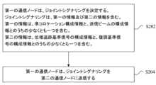
さらに、高周波での位相雑音を推定するために、位相雑音追跡RS(PTRS)が必要とされ得る。これは、高周波では、位相雑音が、時間領域における復調基準信号の推定精度を大幅に低下させるため、システム送信効率を低下させる。一般に、一つのTRPの一つのアンテナパネルが一つの発振器を使用するため、一つのアンテナパネルの複数のDMRSポートが、一つのPTRSポートを共有し得る。すなわち、一つのアンテナパネルの複数のDMRSポートに対して、PTRSポート推定結果が使用され得る。一つのTRPの複数のパネルが、一つの発振器を共有する場合、一つのTRPのすべてのDMRSポートが、一つのPTRSポートを共有し得る。ユーザデバイスは、DMRSポートの共有PTRSポートを通知される。これは、シグナリングオーバヘッド及び物理レイヤリソースオーバヘッドを、可能な限り低減させ得る。これを考慮して、この実施形態は、上記ネットワークアーキテクチャ上で実行される基準信号情報を示すための方法を提供する。図2は、本願の実施形態にしたがって基準信号情報を示すための方法のフローチャートである。図2に示されるように、プロセスは、以下に説明されるステップを含む。 Additionally, a phase noise tracking RS (PTRS) may be required to estimate the phase noise at high frequencies. At high frequencies, this degrades the system transmission efficiency because the phase noise significantly degrades the estimation accuracy of the demodulation reference signal in the time domain. In general, one antenna panel of one TRP uses one oscillator, so multiple DMRS ports of one antenna panel can share one PTRS port. That is, the PTRS port estimation results can be used for multiple DMRS ports of one antenna panel. If multiple panels of one TRP share one oscillator, all DMRS ports of one TRP can share one PTRS port. User devices are notified of the shared PTRS port of the DMRS port. This may reduce signaling overhead and physical layer resource overhead as much as possible. With this in mind, this embodiment provides a method for indicating reference signal information that runs on the above network architecture. FIG. 2 is a flowchart of a method for indicating reference signal information according to embodiments of the present application. As shown in FIG. 2, the process includes steps described below.
ステップS202において、第一の通信ノードは、ジョイントシグナリングを決定する。ジョイントシグナリングは、第一の情報及び第二の情報を含む。第一の情報は、準コロケーション構成情報と、送信ビームの構成情報とのうちの少なくとも一つを含み、第二の情報は、位相追跡基準信号の構成情報と、復調基準信号の構成情報とのうちの少なくとも一つを含む。 At step S202, the first communication node determines joint signaling. Joint signaling includes first information and second information. The first information includes at least one of quasi-colocation configuration information and transmit beam configuration information, and the second information includes phase tracking reference signal configuration information and demodulation reference signal configuration information. contains at least one of
ステップS204において、第一の通信ノードは、ジョイントシグナリングを、第二の通信ノードに送信する。 At step S204, the first communication node transmits joint signaling to the second communication node.
上記ステップにおいて、第一の通信ノードは、ジョイントシグナリングを決定する。ジョイントシグナリングは、第一の情報及び第二の情報を含む。第一の情報は、準コロケーション構成情報と、送信ビーム構成情報とのうちの少なくとも一つを含む。第二の情報は、位相追跡基準信号の構成情報と、復調基準信号の構成情報とのうちの少なくとも一つを含む。第一の通信ノードは、ジョイントシグナリングを、第二の通信ノードへ送信する。上記技術的解決策により、ジョイントシグナリングは、関連技術においてユーザに基準信号情報を通知することによって生じる追加の物理レイヤオーバヘッドの問題を解決する。基準信号情報がユーザ端末に正確に通知されることを保証しながら、ジョイントシグナリングは、物理レイヤオーバヘッドを低減する。 In the above step, the first communication node determines joint signaling. Joint signaling includes first information and second information. The first information includes at least one of quasi-colocation configuration information and transmit beam configuration information. The second information includes at least one of phase tracking reference signal configuration information and demodulation reference signal configuration information. The first communication node transmits joint signaling to the second communication node. With the above technical solution, joint signaling solves the problem of additional physical layer overhead caused by notifying users of reference signal information in related technologies. Joint signaling reduces physical layer overhead while ensuring that reference signal information is accurately signaled to user terminals.
いくつかの実施形態において、上記ステップは、基地局によって実行され得るが、それに限定されない。 In some embodiments, the above steps may be performed by a base station, but are not limited to such.
いくつかの実施形態において、復調基準信号の構成情報は、復調基準信号のシンボル数と、復調基準信号のタイプと、復調基準信号の符号分割タイプと、復調基準信号ポートの順序と、復調基準信号のポートマッピング情報とのうちの少なくとも一つを含む。 In some embodiments, the demodulation reference signal configuration information includes demodulation reference signal symbol number, demodulation reference signal type, demodulation reference signal code division type, demodulation reference signal port order, and demodulation reference signal port mapping information.
いくつかの実施形態において、準コロケーション構成情報は、一つ以上の準コロケーションパラメータサブセットを含み、復調基準信号ポートは、復調基準信号のタイプ1ポートグループを一つ以上含み、一つ以上の準コロケーションパラメータサブセットのおのおのは、復調基準信号の一つ以上のタイプ1ポートグループのそれぞれに対応する。 In some embodiments, the quasi-colocation configuration information includes one or more quasi-colocation parameter subsets, the demodulation reference signal ports include one or more demodulation
いくつかの実施形態において、第一の通信ノードはまた、上位レイヤシグナリングを介して、第二の通信ノードに関する以下の情報、すなわち、準コロケーションパラメータサブセットの最大数と、復調基準信号のタイプ1ポートグループの最大数とのうちの少なくとも一つを構成する。 In some embodiments, the first communication node also transmits, via higher layer signaling, the following information about the second communication node: the maximum number of quasi-colocation parameter subsets and the
いくつかの実施形態において、位相追跡基準信号の構成情報は、位相追跡基準信号ポートの数と、位相追跡基準信号のポート識別子(一つ以上)と、位相追跡基準信号ポートの最大数とのうちの少なくとも一つを含む。 In some embodiments, the phase tracking reference signal configuration information comprises: the number of phase tracking reference signal ports; the phase tracking reference signal port identifier (one or more); and the maximum number of phase tracking reference signal ports. including at least one of
いくつかの実施形態において、準コロケーション構成情報が、一つ以上の準コロケーションパラメータサブセットを含む場合、第一の通信ノードは、ジョイントシグナリングを第二の通信ノードに送信し、ジョイントシグナリングは、一つ以上の準コロケーションパラメータサブセットと位相追跡基準信号のポート識別子(一つ以上)とを含み、一つ以上の準コロケーションパラメータサブセットのおのおのは、位相追跡基準信号ポートのそれぞれに対応する。 In some embodiments, if the quasi-colocation configuration information includes one or more quasi-colocation parameter subsets, the first communication node sends joint signaling to the second communication node, the joint signaling is one and phase tracking reference signal port identifier(s), each of the one or more quasi-colocation parameter subsets corresponding to a respective phase tracking reference signal port.
いくつかの実施形態において、位相追跡基準信号ポートの最大数は、準コロケーションパラメータサブセットの最大数に等しい。 In some embodiments, the maximum number of phase tracking reference signal ports equals the maximum number of quasi-colocation parameter subsets.
いくつかの実施形態において、第一の通信ノードは、ジョイントシグナリングを介して、以下の情報、すなわち、復調基準信号のタイプ1ポートグループが、一つの位相追跡基準信号を共有するか否か、又は、ポートグループが、準コロケーションパラメータの一部に関して準コロケートされているか否かを示す。 In some embodiments, the first communication node may, via joint signaling, provide the following information: whether the
いくつかの実施形態において、復調基準信号のタイプ1ポートグループが二つ、準コロケーションパラメータに関して準コロケートされている場合、復調基準信号の二つのタイプ1ポートグループは、一つの位相追跡基準信号を共有する。準コロケーションパラメータの一部は、ドップラ拡散及びドップラシフトを備える。 In some embodiments, two
いくつかの実施形態において、一つの位相追跡基準信号は、復調基準信号のタイプ2ポートグループの一つに対応し、復調基準信号のタイプ2ポートグループは、復調基準信号のタイプ1ポートグループを一つ以上含む。 In some embodiments, one phase tracking reference signal corresponds to one of the demodulation
いくつかの実施形態において、第一の通信ノードは、準コロケーションパラメータサブセットの数にしたがって、復調基準信号の符号分割タイプを決定する。各符号分割グループにおけるすべての復調基準信号ポートは、同じ準コロケーションパラメータを有し、異なる符号分割グループにおける復調基準信号ポートの準コロケーションパラメータは、同じであるか、又は異なる。符号分割グループタイプ1の符号分割グループに含まれるDMRSポートは、時間領域において使用される同じ符号、及び周波数領域において使用される異なる符号を有する。符号分割グループタイプ2の符号分割グループは、符号分割グループタイプ1の符号分割グループを二つ含み、符号分割グループタイプ1の二つの符号分割グループに含まれる復調基準信号ポートは、同じ時間周波数リソースを占有し、異なる時間領域OCC符号を有する。 In some embodiments, the first communication node determines the code division type of the demodulation reference signal according to the number of quasi-colocation parameter subsets. All demodulation reference signal ports in each code division group have the same quasi-colocation parameter, and the quasi-colocation parameters of demodulation reference signal ports in different code division groups are the same or different. The DMRS ports included in the code division group of code
いくつかの実施形態において、第一の通信ノード及び第二の通信ノードは、復調基準信号の状態を示す複数の情報が、同じ復調基準信号ポートを含み、状態を示す複数の情報によって示される復調基準信号ポートの順序が異なることを承知している。 In some embodiments, the first communication node and the second communication node perform demodulation in which the plurality of information indicating the state of the demodulation reference signal include the same demodulation reference signal port and are indicated by the plurality of information indicating the state. We are aware that the order of the reference signal ports is different.
いくつかの実施形態において、復調基準信号ポートの異なる順序は、異なる準コロケーションパラメータに対応する。 In some embodiments, different orders of demod reference signal ports correspond to different quasi-colocation parameters.
いくつかの実施形態において、第一の通信ノードは、第二の通信に、二つの準コロケーションパラメータセット及び六つのDMRSポートが提供されたことと、六つのDMRSポートが、復調基準信号の一つの時間領域シンボルのみにマッピングされたことを判定し、第一の通信ノードのすべての復調基準信号ポートは、二つの準コロケーションパラメータセットのうち第一の準コロケーションパラメータセットを使用し、二つの準コロケーションパラメータセットのうち第二の準コロケーションパラメータセットは使用しない。 In some embodiments, the first communication node determines that the second communication is provided with two quasi-colocation parameter sets and six DMRS ports, and the six DMRS ports are one of the demodulation reference signals. all demodulation reference signal ports of the first communication node use a first quasi-collocation parameter set of the two quasi-colocation parameter sets, and The second quasi-collocation parameter set of the parameter sets is not used.
いくつかの実施形態において、第一の通信ノードは、ジョイントシグナリングを介して、以下、すなわち、送信ビームの構成情報と、位相追跡基準信号の構成情報とのうちの少なくとも一つを示す。 In some embodiments, the first communication node indicates, via joint signaling, at least one of the following: transmit beam configuration information and phase tracking reference signal configuration information.
いくつかの実施形態において、送信ビームの構成情報は、サウンディング基準信号リソースを示す情報と、プリコーディング情報インジケーションとのうちの少なくとも一つを含む。サウンディング基準信号リソースを示す情報は、リソースを識別するための識別子(すなわち、今回構成されたサウンディング基準信号のどのリソースが、この識別子によって識別されるのかのための識別子)を含むことに留意されたい。リソース情報の識別子は、インデクスに類似している。 In some embodiments, the transmit beam configuration information includes at least one of information indicating sounding reference signal resources and precoding information indication. Note that the information indicating the sounding reference signal resource includes an identifier for identifying the resource (that is, an identifier for which resource of the currently configured sounding reference signal is identified by this identifier). . Identifiers of resource information are similar to indexes.
いくつかの実施形態において、サウンディング基準信号リソースを示す情報は、位相追跡基準信号のポート情報を含む。 In some embodiments, the information indicative of sounding reference signal resources includes phase tracking reference signal port information.
いくつかの実施形態において、サウンディング基準信号の一つ以上のリソースは、サウンディング基準信号リソースセットを構築し、各サウンディング基準信号リソースセットは、位相追跡基準信号の同じポート情報に対応する。 In some embodiments, one or more resources of the sounding reference signal make up a sounding reference signal resource set, each sounding reference signal resource set corresponding to the same port information of the phase tracking reference signal.
いくつかの実施形態において、上位レイヤシグナリングによって構成されるサウンディング基準信号のリソース構成情報は、位相追跡基準信号のポート識別子を含む。本明細書において、上位レイヤシグナリングは、無線リソース制御シグナリング又はメディアアクセス制御シグナリングを含み得る。サウンディング基準信号のリソース構成情報は、位相追跡基準信号の一つ以上のポート識別子を伝送する。 In some embodiments, the sounding reference signal resource configuration information configured by higher layer signaling includes the phase tracking reference signal port identifier. As used herein, higher layer signaling may include radio resource control signaling or media access control signaling. The sounding reference signal resource configuration information conveys one or more port identifiers of the phase tracking reference signal.
基準信号情報を示すための方法は、本願の別の実施形態によって提供される。この方法は、第二の通信ノードに適用され、以下に説明するステップを含む。 A method for indicating reference signal information is provided by another embodiment of the present application. The method is applied to the second communication node and includes the steps described below.
ステップ1では、第二の通信ノードは、第一の通信ノードによって送信されたジョイントシグナリングを受信する。ジョイントシグナリングは、第一の情報及び第二の情報を含む。第一の情報は、準コロケーション構成情報と、送信ビームの構成情報とのうちの少なくとも一つを含む。第二の情報は、位相追跡基準信号の構成情報と、復調基準信号の構成情報とのうちの少なくとも一つを含む。 In
ステップ2において、第二の通信ノードは、ジョイントシグナリングにしたがって、第一の通信ノードによって送信されたデータを受信し、及び/又は、第一の通信ノードとのデータ送信を実行する。 In
いくつかの実施形態において、復調基準信号の構成情報は、復調基準信号のシンボル数と、復調基準信号のタイプと、復調基準信号の符号分割タイプと、復調基準信号ポートの順序と、復調基準信号のポートマッピング情報とのうちの少なくとも一つを含む。 In some embodiments, the demodulation reference signal configuration information includes demodulation reference signal symbol number, demodulation reference signal type, demodulation reference signal code division type, demodulation reference signal port order, and demodulation reference signal port mapping information.
いくつかの実施形態において、準コロケーション構成情報は、一つ以上の準コロケーションパラメータサブセットを含む。復調基準信号ポートは、復調基準信号のタイプ1ポートグループを一つ以上含む。一つ以上の準コロケーションパラメータサブセットのおのおのは、復調基準信号の一つ以上のタイプ1ポートグループのそれぞれに対応する。 In some embodiments, the quasi-colocation configuration information includes one or more quasi-colocation parameter subsets. The demodulation reference signal ports include one or more demodulation
いくつかの実施形態において、第二の通信ノードは、上位レイヤシグナリングを介して、第一の通信ノードによって構成された、以下の情報、すなわち、準コロケーションパラメータサブセットの最大数と、復調基準信号のタイプ1ポートグループの最大数とのうちの少なくとも一つを受信する。 In some embodiments, the second communication node receives, via higher layer signaling, the following information configured by the first communication node: the maximum number of quasi-colocation parameter subsets and the number of demodulation reference signals. and the maximum number of
いくつかの実施形態において、位相追跡基準信号の構成情報は、位相追跡基準信号ポートの数と、位相追跡基準信号の一つ以上のポート識別子と、位相追跡基準信号ポートの最大数とのうちの少なくとも一つを含む。 In some embodiments, the configuration information of the phase tracking reference signal is one of the number of phase tracking reference signal ports, one or more port identifiers of the phase tracking reference signal, and the maximum number of phase tracking reference signal ports. contains at least one
いくつかの実施形態において、準コロケーション構成情報が、一つ以上の準コロケーションパラメータサブセットを含む場合、第二の通信ノードは、第一の通信によって送信されたジョイントシグナリングを受信する。ジョイントシグナリングは、一つ以上の準コロケーションパラメータサブセットと、位相追跡基準信号のポート識別子(一つ以上)とを含み、一つ以上の準コロケーションパラメータサブセットのおのおのは、位相追跡基準信号ポートのそれぞれに対応する。 In some embodiments, the second communication node receives joint signaling sent by the first communication if the quasi-colocation configuration information includes one or more quasi-colocation parameter subsets. The joint signaling includes one or more quasi-colocation parameter subsets and one or more phase tracking reference signal port identifiers, each of the one or more quasi-colocation parameter subsets for each of the phase tracking reference signal ports. handle.
いくつかの実施形態において、位相追跡基準信号ポートの最大数は、準コロケーションパラメータサブセットの最大数に等しい。 In some embodiments, the maximum number of phase tracking reference signal ports equals the maximum number of quasi-colocation parameter subsets.
いくつかの実施形態において、第二の通信ノードは、ジョイントシグナリングにより通知された、以下の情報、すなわち、復調基準信号のタイプ1ポートグループが、一つの位相追跡基準信号を共有するか否か、又は、それらのポートグループが、準コロケーションパラメータの一部に関して準コロケートされているか否かを受信する。 In some embodiments, the second communication node is notified by joint signaling of the following information: whether the demodulation
いくつかの実施形態において、準コロケーションパラメータに関して、復調基準信号のタイプ1ポートグループが二つ準コロケートされている場合、復調基準信号のそれら二つのタイプ1ポートグループは、一つの位相追跡基準信号を共有し、準コロケーションパラメータの一部は、ドップラ拡散及びドップラシフトを含む。 In some embodiments, if two
いくつかの実施形態において、一つの位相追跡基準信号は、復調基準信号のタイプ2ポートグループの一つに対応し、復調基準信号のタイプ2ポートグループは、復調基準信号のタイプ1ポートグループを一つ以上含む。 In some embodiments, one phase tracking reference signal corresponds to one of the demodulation
いくつかの実施形態において、復調基準信号の符号分割タイプは、準コロケーションパラメータサブセットの数にしたがって、第一の通信ノードによって決定される。各符号分割グループにおけるすべての復調基準信号ポートは、同じ準コロケーションパラメータを有し、異なる符号分割グループにおける復調基準信号ポートの準コロケーションパラメータは、同じであるか、又は異なる。符号分割グループタイプ1の符号分割グループに含まれるDMRSポートは、時間領域において使用される同じ符号と、周波数領域において使用される異なる符号とを有する。符号分割グループタイプ2の符号分割グループは、符号分割グループタイプ1の符号分割グループを二つ含み、符号分割グループタイプ1の符号分割グループ二つに含まれる復調基準信号ポートは、同じ時間周波数リソースを占有し、異なる時間領域OCC符号を有する。 In some embodiments, the code division type of the demodulation reference signal is determined by the first communication node according to the number of quasi-colocation parameter subsets. All demodulation reference signal ports in each code division group have the same quasi-colocation parameter, and the quasi-colocation parameters of demodulation reference signal ports in different code division groups are the same or different. The DMRS ports included in the code division group of code
いくつかの実施形態において、第二の通信ノード及び第一の通信ノードは、復調基準信号の構成情報の状態を示す複数の情報が、同じ復調基準信号ポートを備え、状態を示す複数の情報によって示される復調基準信号ポートの順序が異なることを承知している。 In some embodiments, the second communication node and the first communication node are arranged such that the plurality of information indicating the status of the demodulation reference signal configuration information comprise the same demodulation reference signal port, and the plurality of information indicating the status It is noted that the order of demod reference signal ports shown is different.
いくつかの実施形態において、復調基準信号ポートの異なる順序は、異なる準コロケーションパラメータに対応する。 In some embodiments, different orders of demod reference signal ports correspond to different quasi-colocation parameters.
いくつかの実施形態において、第二の通信ノードが、二つの準コロケーションパラメータセット及び六つのDMRSポートを与えられ、六つのDMRSポートが、復調基準信号の一つの時間領域シンボルのみにマッピングされる場合、第一の通信ノードのすべての復調基準信号ポートは、二つの準コロケーションパラメータセットのうちの第一の準コロケーションパラメータセットを使用し、二つの準コロケーションパラメータセットのうちの第二の準コロケーションパラメータセットは使用しない。 In some embodiments, if the second communication node is provided with two quasi-colocation parameter sets and six DMRS ports, and the six DMRS ports are mapped to only one time domain symbol of the demodulation reference signal. , all demodulation reference signal ports of the first communication node use a first quasi-colocation parameter set of the two quasi-colocation parameter sets, and a second quasi-colocation parameter set of the two quasi-colocation parameter sets. Do not use sets.
いくつかの実施形態において、第二の通信ノードは、ジョイントシグナリングを介して、以下の情報、すなわち、送信ビームの構成情報と、位相追跡基準信号の構成情報とのうちの少なくとも一つを受信する。 In some embodiments, the second communication node receives at least one of the following information via joint signaling: transmission beam configuration information and phase tracking reference signal configuration information .
いくつかの実施形態において、送信ビームの構成情報は、サウンディング基準信号リソースを示す情報と、プリコーディング情報インジケーションとのうちの少なくとも一つを含む。 In some embodiments, the transmit beam configuration information includes at least one of information indicating sounding reference signal resources and precoding information indication.
いくつかの実施形態において、サウンディング基準信号リソースを示す情報は、位相追跡基準信号のポート情報を含む。 In some embodiments, the information indicative of sounding reference signal resources includes phase tracking reference signal port information.
いくつかの実施形態において、サウンディング基準信号の一つ以上のリソースは、サウンディング基準信号リソースセットを構築し、各サウンディング基準信号リソースセットは、位相追跡基準信号の同じポート情報に対応する。 In some embodiments, one or more resources of the sounding reference signal make up a sounding reference signal resource set, each sounding reference signal resource set corresponding to the same port information of the phase tracking reference signal.
本願は、例と併せて以下に詳細に説明される。 The present application is described in detail below in conjunction with examples.
[DMRSタイプ2の例]
現在、基準信号の設計のために、周波数領域直交カバーリング符号(FD-OCC)に基づくDMRSパターンは、DMRSタイプ2と称される。DMRSタイプ2は、実質的に、(図3に示すように)一つのDMRSシンボルにおいて最大六つのポートをサポートし、(図4に示すように)二つのDMRSシンボルにおいて最大十二のポートをサポートする。[Example of DMRS type 2]
Currently, for the design of reference signals, DMRS patterns based on frequency-domain orthogonal covering codes (FD-OCC) are referred to as DMRS type-2.
図3は、上記実施形態にしたがう復調基準信号タイプ2の概略図1である。図3に示すように、一つのリソースブロック(RB)において、横軸は時間領域、縦軸は周波数領域である。六つのDMRSポートは、三つの符号分割多重化(CDM)グループに分割される。CDMグループ#0は、ポートp0及びポートp1を含む。CDMグループ#0において、ポートp0及びポートp1は、OCC分割を介して、同じ時間周波数リソースにマッピングされる。たとえば、ポートp0によって使用されるOCCは、[1 1]であり、ポートp1によって使用されるOCCは、[1 -1]である。一つのRBにおいて、ポートp0及びp1によってマッピングされるサブキャリアは、サブキャリア#4、#5、#10及び#11を含む。同様に、CDMグループ#1は、ポートp2及びポートp3を含む。CDMグループ#1において、ポートp2及びポートp3は、OCC分割を介して、同じ時間周波数リソースにマッピングされる。たとえば、ポートp2によって使用されるOCCは[1 1]であり、ポートp3によって使用されるOCCは[1 -1]である。CDMグループ#2は、ポートp4及びポートp5を含む。CDMグループ#2において、ポートp4及びポートp5は、OCC分割を介して、同じ時間周波数リソースにマッピングされる。たとえば、ポートp4によって使用されるOCCは[1 1]であり、ポートp5によって使用されるOCCは[1 -1]である。六つのDMRSポートは、一人のユーザ、すなわち、シングルユーザMIMO(SU-MIMO)に割り当てられ得、複数のユーザ、すなわち、マルチユーザMIMO(MU-MIMO)にも割り当てられ得る。図におけるパターンは、最大六つのDMRSポートをサポートし得るが、実際にユーザをスケジュールするときに、基地局は、必ずしもユーザに六つのDMRSポートを割り当てるとは限らない。たとえば、セルが、少数のユーザを有し、ユーザによって必要とされるポートの数が少ない場合、基地局は、一つ又は二つのポートしか必要としない。ここでのポートは論理ポートであり得、一つ又は二つのポートを送信することは、DMRSなどの一つ又は二つのポートに対応する信号を送信することであり得る。 FIG. 3 is a schematic diagram 1 of demodulation
すべての準コロケーションパラメータに関して準コロケートされているポートである、DMRSポートグループすなわちDMRSグループは、DMRSのタイプ1ポートグループと称され得る。DMRSのタイプ1ポートグループは、タイプ1ポートグループであり、タイプ1ポートグループは、DMRSを送信するために使用され得、したがって、DMRSタイプのポートグループと称されることに留意されたい。DMRSのタイプ1ポートグループによって送信されるDMRSは、DMRSタイプ1及び/又はDMRSタイプ2であり得る。DMRSタイプ1及びDMRSタイプ2は、両方ともDMRSタイプであるが、異なるDMRSタイプである。DMRSタイプとポートグループタイプとには、特定の関係はない。 A DMRS port group or DMRS group, which are ports that are quasi-colocated with respect to all quasi-colocation parameters, may be referred to as a
符号分割復調をより簡単に実行するために、同じCDMグループにおける二つのDMRSポートが同じパラメータを有する。このようにすると、インターコード復調を実行するとき、干渉ポートのQCLは、ターゲット復調ポートのQCLと同じであり、これは正確な復調に有益である。 Two DMRS ports in the same CDM group have the same parameters in order to perform code division demodulation more easily. In this way, when performing inter-code demodulation, the QCL of the interfering port is the same as the QCL of the target demodulation port, which is beneficial for accurate demodulation.
図4は、例1にしたがう復調基準信号タイプ2の概略図2である。図4に示すように、復調基準信号が二つのDMRSシンボルを有する場合、最大十二のDMRSポートがサポートされ得る。十二のDMRSポートは、三つのCDMグループに分割され得る。CDMグループ#0は、ポートp0、ポートp1、ポートp6、及びポートp7を含む。CDMグループ#1は、ポートp2、ポートp3、ポートp8、及びポートp9を含む。CDMグループ#2は、ポートp4、ポートp5、ポートp10、及びポートp11を含む。CDMグループ#0において、ポートp0、ポートp1、ポートp6、及びポートp7は、同じ時間周波数リソースを占有するが、使用される時間領域OCC又は周波数領域OCCは異なる。たとえば、ポートp0及びポートp1は、周波数領域OCCで区別されるが、時間領域OCCは同じであり、すなわち、ポートp0によって使用される周波数領域OCCは、[1 1]であり、ポートp1によって使用される周波数領域OCCは、[1 -1]であるが、ポートp0及びポートp1は、同じ時間領域OCC[1 1]を使用する。p6及びp7は、周波数領域OCCによって区別されるが、それらの時間領域OCCは同じであり、すなわち、ポートp6によって使用される周波数領域OCCは、[1 1]であり、ポートp7によって使用される周波数領域OCCは、[1 -1]であるが、ポートp6及びポートp7は、同じ時間領域OCC[1 -1]を使用する。同様に、他の各CDMグループにおける四つのポートも、同じ手法で構成される。CDMグループ#1において、ポートp2及びポートp3は、異なる周波数領域OCCを使用するが、同じ時間領域OCCを使用する。ポートp8及びポートp9は、異なる周波数領域OCCを使用するが、同じ時間領域OCCを使用する。ポートp2及びポートp3によって使用される時間領域OCCは、ポートp8及びポートp9によって使用される時間領域OCCとは異なる。CDMグループ#2では、ポートp4及びポートp5は、異なる周波数領域OCCを使用するが、同じ時間領域OCCを使用する。ポートp10及びポートp11は、異なる周波数領域OCCを使用するが、同じ時間領域OCCを使用する。しかし、ポートp4及びポートp5によって使用される時間領域OCCは、ポートp10及びポートp11によって使用される時間領域OCCとは異なる。このタイプのCDMグループは、CDMグループタイプ2、すなわち、符号分割グループタイプ2と称される。 4 is a schematic diagram 2 of demodulation
符号分割復調をより簡単に実行するために、同じCDMグループにおける四つのDMRSポートは、事前定義された手法で同じQCLパラメータを有するように構成され得る。しかし、CDMグループの数は三つまでに制限される。 In order to perform code division demodulation more easily, four DMRS ports in the same CDM group can be configured to have the same QCL parameters in a predefined manner. However, the number of CDM groups is limited to three.
本願では、ポートp0~p11は整数であるが、必ずしも連続した整数であるとは限らない。たとえば、ポートp0~p11は、実際にはポート1000~1011を表し得る。 In this application, ports p0-p11 are integers, but not necessarily consecutive integers. For example, ports p0-p11 may actually represent ports 1000-1011.
一般に、高周波では、NR基地局に、複数のアンテナパネルが設けられ得る。各パネルは、異なる復調基準信号ポートに対応する異なるアナログビームを送信し得る。もちろん、一つのパネルが、複数のデジタルビームに対応する一つのアナログビームを送信することもできる。これらのデジタルビームは、異なるDMRSポートに対応している。複数のパネルによって送信される異なるビームは、複数のDMRSポートに対応するため、複数のポートが対応するQCLは、同じであり得るか、又は異なり得る。 Generally, at high frequencies, an NR base station may be provided with multiple antenna panels. Each panel may transmit different analog beams corresponding to different demodulation reference signal ports. Of course, one panel can also transmit one analog beam corresponding to multiple digital beams. These digital beams correspond to different DMRS ports. Since different beams transmitted by multiple panels correspond to multiple DMRS ports, the QCLs to which the multiple ports correspond may be the same or different.
マルチTRP送信において、各TRPが複数のパネルを有する場合、CDMグループの数が三つに制限されるのであれば、DMRSグループの数は三つに制限される。すなわち、異なるQCLを有する最大三つのビーム送信がサポートされ、これは、スケジューリングを制限し得る。 In multi-TRP transmission, if each TRP has multiple panels, the number of DMRS groups is limited to three if the number of CDM groups is limited to three. That is, up to three beam transmissions with different QCLs are supported, which may limit scheduling.
図4に示すように、二つのDMRSシンボルを有するパターンの場合、任意選択の変形例として、十二のDMRSポートは、六つのCDMグループに分割され得る。CDMグループ#0は、ポートp0及びp1を含み、ポートp0及びポートp1は、異なる周波数領域OCCによって区別される。たとえば、ポートp0によって使用される周波数領域OCCは、[1 1]であり、ポートp1によって使用される周波数領域OCCは、[1 -1]である。CDMグループ#1は、ポートp2及びp3を含み、ポートp2及びポートp3は、異なる周波数領域OCCによって区別される。CDMグループ#2は、ポートp4及びp5を含み、ポートp4及びポートp5は、異なる周波数領域OCCによって区別される。CDMグループ#3は、ポートp6及びp7を含み、ポートp6及びポートp7は、異なる周波数領域OCCによって区別される。CDMグループ#4は、ポートp8及びp9を含み、ポートp8及びポートp9は、異なる周波数領域OCCによって区別される。CDMグループ#5は、ポートp10及びp11を含み、ポートp10及びポートp11は、異なる周波数領域OCCによって区別される。一方、CDMグループ#0におけるポートと、CDMグループ#3におけるポートとは、同じ時間周波数リソースを占有するが、異なる時間領域OCCを使用する。たとえば、CDMグループ#0におけるポートp0及びp1によって使用される時間領域OCCは[1 1]である一方、CDMグループ#3におけるポートp6及びp7によって使用される時間領域OCCは[1 -1]である。CDMグループ#1におけるポートと、CDMグループ#4におけるポートとは、同じ時間周波数リソースを占有するが、異なる時間領域OCCを使用する。たとえば、CDMグループ#1におけるポートp2及びp3によって使用される時間領域OCCは、[1 1]である一方、CDMグループ#4におけるポートp8及びp9によって使用される時間領域OCCは、[1 -1]である。CDMグループ#2におけるポートと、CDMグループ#5におけるポートとは、同じ時間周波数リソースを占有するが、異なる時間領域OCCを使用する。たとえば、CDMグループ#2におけるポートp4及びp5によって使用される時間領域OCCは、[1 1]である一方、CDMグループ#5におけるポートp10及びp11によって使用される時間領域OCCは、[1 -1]である。同様に、各CDMグループにおけるすべてのDMRSポートは、同じQCLパラメータを有しており、異なるCDMグループにおけるDMRSポートは、異なるQCLパラメータを有し得る。QCLパラメータが異なることは、QCLパラメータセットにおけるいくつかのQCLパラメータ又はすべてのQCLパラメータが異なることを意味する。このタイプのCDMグループは、タイプ1のCDMグループ、すなわち、符号分割グループタイプ1と称される。 For a pattern with two DMRS symbols, as shown in FIG. 4, as an optional variant, twelve DMRS ports may be divided into six CDM groups.
二つのDMRSシンボルを有するパターンの場合、CDMグループタイプを通知するための方法は、基地局が、シグナリングを介してCDMグループタイプをユーザに通知することを含み得る。上位レイヤシグナリングは、上位レイヤRRCシグナリングを含み得、MACシグナリング又は物理レイヤ動的シグナリングも含まれ得る。各CDMグループにおけるDMRSポートのすべては、同じQCLパラメータを有する。異なるCDMグループにおけるDMRSポートには、異なるQCLパラメータを有し得る。CDMグループタイプ1のCDMグループにおけるDMRSポートは、時間領域において同じ符号を使用し、周波数領域において異なる符号を使用する。タイプ2のCDMグループの場合、タイプ2のCDMグループ一つは、タイプ1のCDMグループを二つ含み、タイプ1のCDMグループ二つに含まれるDMRSポートは、同じ時間周波数リソースを占有し、それらの時間領域OCCは異なる。タイプ1のCDMグループの各CDMグループに含まれるDMRSポートの数は、タイプ2のCDMグループの各CDMグループに含まれるDMRSポートの数の半分である。 For patterns with two DMRS symbols, the method for signaling the CDM group type may include the base station signaling the CDM group type to the user via signaling. Higher layer signaling may include higher layer RRC signaling and may also include MAC signaling or physical layer dynamic signaling. All of the DMRS ports in each CDM group have the same QCL parameters. DMRS ports in different CDM groups may have different QCL parameters. The DMRS ports in a CDM group of
このように、少数のアンテナパネルを有する基地局、又は、マルチTRP送信を使用しないユーザについては、基地局は、タイプ1のCDMグループで構成され得、そうでない場合は、タイプ2のCDMグループで構成される必要がある。 Thus, for base stations with a small number of antenna panels, or for users who do not use multi-TRP transmission, the base station may be configured with
任意選択の変形例として、基地局は、CDMグループ(符号領域グループ)タイプを直接通知することなく、ユーザへの上位レイヤシグナリングによって構成される復調基準信号のポートグループの最大数のみを必要とする。復調基準信号のポートグループの最大数がしきい値を超える場合、CDMグループタイプはタイプ1であり、そうでない場合はタイプ2である。 As an optional variant, the base station only needs the maximum number of demod reference signal port groups configured by higher layer signaling to the user without directly signaling the CDM group (code domain group) type. . If the maximum number of port groups of demodulation reference signals exceeds the threshold, the CDM group type is
複数のDMRSポートを一人のユーザに送信する場合、複数のDMRSポートは、複数のタイプ1のDMRSポートグループに分割され得る。各DMRSポートグループにおけるすべてのポートのすべてのQCLパラメータは同じである一方、異なるDMRSポートグループにおけるポートのQCLパラメータは異なり得る。そのため、一つのDMRSポートグループは、一つ以上のCDMグループからのDMRSポートを含み得、これらのポートのすべてのQCLパラメータは同じである。しかしながら、異なるDMRSグループにおけるDMRSポートのQCLパラメータは、異なり得る。この場合、各DMRSグループのQCLパラメータ情報は、シグナリングによって基地局によってユーザに示される必要がある。 When transmitting multiple DMRS ports to one user, the multiple DMRS ports may be divided into
LTEと同様に、基地局は、上位レイヤシグナリングによって、ユーザのためのPQIパラメータの複数のセットを構成し得る。PQIパラメータの各セットは、PDSCHマッピングと、QCLパラメータ関連情報とを含み、これらは、ユーザに、チャネル状態情報基準信号(CSI-RS)構成識別子(ID)を示し得る。ユーザは、DMRS及びデータを受信すると、この構成IDに対応するRSを使用して、QCLのいくつかのパラメータの関連する推定を実行する。たとえば、ドップラシフト、ドップラ拡散、平均遅延、及び遅延拡散を推定するためにCSI-RSが使用され、その後、推定結果が、DMRS及びデータ復調のために使用される。一方、csi-RS-ConfigZPId-r11などの他のパラメータは、いくつかのゼロ電力基準信号又は他の基準信号のユーザ位置を示すために使用される。つまり、これらの位置ではデータは送信されない。このようにして、UEは、データチャネルマッピング又はレートマッチングを実行する方法を知る。通常、上位レイヤは、PQIパラメータセットの四つのセットを構成し、その後、DCIにおける2ビットを使用して、ユーザに対してPQIパラメータセットのうちの一つを選択する。 Similar to LTE, a base station may configure multiple sets of PQI parameters for a user through higher layer signaling. Each set of PQI parameters includes PDSCH mapping and QCL parameter related information, which may indicate a Channel State Information Reference Signal (CSI-RS) Configuration Identifier (ID) to the user. Once the user receives the DMRS and data, it uses the RS corresponding to this configuration ID to perform the relevant estimation of some parameters of the QCL. For example, CSI-RS is used to estimate Doppler shift, Doppler spread, mean delay, and delay spread, and then the estimation results are used for DMRS and data demodulation. On the other hand, other parameters such as csi-RS-ConfigZPId-r11 are used to indicate the user's position of some zero-power reference signals or other reference signals. That is, no data is transmitted at these locations. This way the UE knows how to perform data channel mapping or rate matching. Typically, higher layers configure four sets of PQI parameter sets and then use two bits in the DCI to select one of the PQI parameter sets for the user.
NRにおいて、複数のDMRSグループが、異なるQCLパラメータに対応する場合が存在し、各PQIパラメータセットに含まれるパラメータは、変動し得る。上位レイヤシグナリングを介して基地局によって一人のユーザに対して構成される、DMRSポートグループの最大数は2である。つまり、各PQIパラメータセットは、
{
データチャネルマッピング又はレートマッチングのために使用されるパラメータサブセット1、
基準信号構成ID#0を示し、関連するQCLパラメータを推定するパラメータサブセット2-1、
基準信号構成ID#1を示し、関連するQCLパラメータを推定するパラメータサブセット2-2
}
のように、QCLの二つのセットの関連情報で構成されるべきである。In NR, multiple DMRS groups may correspond to different QCL parameters, and the parameters included in each PQI parameter set may vary. The maximum number of DMRS port groups configured for one user by the base station via higher layer signaling is two. That is, each PQI parameter set is
{
a parameter subset 2-1 indicating reference signal
A parameter subset 2-2 that indicates the reference signal
}
It should consist of two sets of related information in the QCL, such as:
基準信号構成ID#0が対応する基準信号と、DMRSポートグループ#0とは、QCL関係を有する。基準信号構成ID#1が対応する基準信号と、DMRSポートグループ#1とは、QCL関係を有する。基準信号構成ID#0又は基準信号構成ID#1が対応する基準信号は、同期信号ブロック(SSブロック)と、CSI-RSと、追跡基準信号(TRS)とのうちの一つ以上であり得る。一般に、QCLパラメータは、ドップラシフト、ドップラ拡散、平均遅延、遅延拡散、及び空間Rxパラメータを含む。したがって、基準信号構成ID#iが対応する基準信号及びDMRSポートグループ#iは、ドップラシフト、ドップラ拡散、平均遅延、遅延拡散、及び空間Rxパラメータに関して準コロケートされている。具体的には、基準信号構成ID#iが、複数の基準信号を含む場合、複数の基準信号の用途は異なり得る。たとえば、基準信号構成ID#iは、CSI-RS及び追跡基準信号(TRS)を含む。CSI-RS及びDMRSは、平均遅延、遅延拡散、及び空間Rxパラメータに関して準コロケートされる一方、TRS及びDMRSは、ドップラシフト及びドップラ拡散に関して準コロケートされている。 The reference signal corresponding to reference signal
マルチパネル送信について、すべてのデータ及びDMRSポートが、同じ発振器からのものである場合、一つのPTRSポートのみ必要とされる。複数のDMRSポートが、異なる発振器からのものである場合、異なるPTRSポートが必要とされる。同様に、マルチTRP送信について、複数のTRPが、異なる発振器を有するため、複数のPTRSポートが必要とされる。しかしながら、シングルTRP送信とマルチTRP送信との間で、及び、シングルパネル送信とマルチパネル送信との間で動的に変動する場合、異なるポートが必要とされる。つまり、PTRSポートは、複数のポートが必要な場合があり、単一の信号ポートが必要な場合があり、異なるセル又は異なるユーザは、異なる要件を有する。たとえば、シングルパネルを有するTRP#0の場合、TRP#0に接続されたUE#0は、セル中心のユーザであり、マルチTRP送信は必要とされない。したがって、一つのPTRSポートのみが必要とされる。別のUE#1は、セルエッジユーザであり、マルチTRP送信が必要とされ、この場合、複数のPTRSポートが必要とされ得る。シグナリングオーバヘッドを抑えるために、基地局は、上位レイヤシグナリングによって、各ユーザのPTRSポートの最大数を構成し得、実際に送信されるPTRSの数を動的に選択し得る。たとえば、上位レイヤシグナリングによってUE#0のために構成されたPTRSポートの最大数が1である場合、PTRSポートの数は、動的に通知される必要はない。上位レイヤシグナリングによってUE#0のために構成されたPTRSポートの最大数が2である場合、PTRSポートの数が、一つ又は二つであることを動的に通知するには、1ビットのシグナリングが必要とされる。上位レイヤシグナリングによってUE#0のために構成されたPTRSポートの最大数が4である場合、PTRSポートの数を動的に通知するには、2ビットのシグナリングが必要とされる。このように、異なる場合のための動的なシグナリングオーバヘッドが効果的に抑えられ得る。しかしながら、この方法はでもまだ、PTRSポートの最大数を示す正確なシグナリングが必要である。 For multi-panel transmission, only one PTRS port is required if all data and DMRS ports are from the same oscillator. If multiple DMRS ports are from different oscillators, different PTRS ports are required. Similarly, for multi-TRP transmission, multiple PTRS ports are required because multiple TRPs have different oscillators. However, different ports are required when dynamically varying between single-TRP and multi-TRP transmissions and between single-panel and multi-panel transmissions. That is, a PTRS port may require multiple ports, may require a single signaling port, and different cells or different users have different requirements. For example, for
PTRSポートの最大数を示すための方法は、PTRSポートの最大数が、タイプ1のDMRSポートグループの最大数に等しいことを含み得る。タイプ1のDMRSポートグループにおけるすべてのDMRSポートは、すべてのQCLパラメータに関して準コロケートされている。同じDMRSポートグループにおけるDMRSポートは、すべてのQCLパラメータに関して準コロケートされているので、一つのDMRSグループには、最大で一つのPTRSポートが必要である。異なるDMRSポートグループ間のQCLパラメータは、固定されていない。各DMRSポートグループは、一つのPTRSポートを必要とし得るので、PTRSポートの最大数は、シグナリングによって通知されない場合があるが、タイプ1のDMRSポートグループの最大数に等しくなるように事前定義される。このように、上位レイヤシグナリングオーバヘッドが効果的に抑えられ得る。 The method for indicating the maximum number of PTRS ports may include that the maximum number of PTRS ports is equal to the maximum number of
すなわち、異なるDMRSポートグループは、異なるTRPからのもの、又は一つのTRPの異なるアンテナパネルからのものであり得るので、各DMRSポートグループは、位相雑音を推定するために一つのPTRSポートを必要とする。異なるTRPは、異なる発振器を有し、異なるアンテナパネルは、異なる発振器を有し得、異なる水晶発振器によって生成される位相雑音は異なるので、PTRSポートは、個別に構成される必要がある。簡略化のために、DMRSポートグループはすべて、デフォルトで一つのPTRSポートを有し得る。このように、PTRSポートの数はDMRSポートグループの数と等しいため、基地局は、PTRSポートの数を追加で通知する必要はない。一方、PTRSは、そのPTRSに対応するDMRSポートグループにおける最小のポート識別子を有するDMRSポートに接続される。つまり、PTRSポートのプリコーディングは、対応するDMRSポートグループにおける最小のポート識別子を有するDMRSポートのプリコーディングと同じである。 That is, different DMRS port groups can be from different TRPs or from different antenna panels of one TRP, so each DMRS port group requires one PTRS port to estimate phase noise. do. Since different TRPs have different oscillators, different antenna panels may have different oscillators, and the phase noise generated by different crystal oscillators is different, the PTRS ports need to be configured individually. For simplicity, all DMRS port groups may have one PTRS port by default. Thus, since the number of PTRS ports is equal to the number of DMRS port groups, the base station does not need to additionally notify the number of PTRS ports. On the other hand, a PTRS is connected to the DMRS port with the lowest port identifier in the DMRS port group corresponding to that PTRS. That is, the precoding of the PTRS port is the same as the precoding of the DMRS port with the lowest port identifier in the corresponding DMRS port group.
QCLパラメータは、平均利得、ドップラシフト、ドップラ拡散、平均遅延、遅延拡散、及び空間Rxパラメータを含むか、又は、平均利得、ドップラシフト、ドップラ拡散、平均遅延、及び遅延拡散のみを含み、これは異なる場合に依存することに留意されたい。 The QCL parameters include average gain, Doppler shift, Doppler spread, average delay, delay spread, and spatial Rx parameters, or only average gain, Doppler shift, Doppler spread, average delay, and delay spread, which are Note that it depends on different cases.
DMRSは一つのシンボルのみを有し、最大六つのポートをサポートし、DMRSパターンは図3に示されるものと仮定する。DMRSポートグループの最大数は2であり、上位レイヤシグナリング(RRCシグナリング、又はMAC CEシグナリングと組み合わされたRRCシグナリング)によって準静的に構成されていると仮定する。DMRSポートの数と組み合わせて、DMRSグループは、CDMグループに対応するように事前に構成され得る。一つのCDMグループにおけるDMRSポートは、一つのDMRSグループにのみ属する。もちろん、一つのDMRSグループは、一つ以上のCDMグループが対応するポートを含み得る。表1は、例1にしたがう復調基準信号情報インジケーション表である。表1に示すように、インジケーション6において、p0は、DMRSグループ0に対応し、p2は、DMRSグループ1に対応する。この対応関係は、シグナリングによる通知なしで表に事前に定義され得る。 Assume that the DMRS has only one symbol, supports up to 6 ports, and the DMRS pattern is shown in FIG. It is assumed that the maximum number of DMRS port groups is 2 and semi-statically configured by higher layer signaling (RRC signaling or RRC signaling combined with MAC CE signaling). In combination with the number of DMRS ports, DMRS groups can be preconfigured to correspond to CDM groups. A DMRS port in one CDM group belongs to only one DMRS group. Of course, one DMRS group may include ports to which one or more CDM groups correspond. Table 1 is a demodulation reference signal information indication table according to Example 1. As shown in Table 1, in
DMRSポートグループの最大数は2であるため、PTRSポートの最大数は2である。DMRSグループが一つだけ提供されている場合には、PTRSはポートm0であり、そうでない場合には、PTRSは、ポートm0及びm1である。表に示すように、インジケーション7などにおいて、ポートp1及びp3はそれぞれ、PTRSポートm0及びm1に対応している。インジケーション9において、ポートp0及びp1は、m0に対応し、ポートp2は、m1に対応し、m0及びp1はマッチする。つまり、m0及びp1は、同じプリコーディングを有する。インジケーション10において、ポートp3はm0に対応し、p4及びp5はm1に対応し、m1及びp4はマッチする。m1及びp4は、同じプリコーディングを有する。 Since the maximum number of DMRS port groups is two, the maximum number of PTRS ports is two. If only one DMRS group is provided, the PTRS is port m0, otherwise the PTRS are ports m0 and m1. As shown in the table, ports p1 and p3 correspond to PTRS ports m0 and m1, respectively, in

DMRSポートグループにおけるすべてのQCLパラメータは、同じである。PTRSのプリコーディングは、マッチしたDMRSポートのプリコーディングと同じであるため、PTRSと、これにマッチしたDMRSポートとは、QCLパラメータセットのすべてのパラメータに関して準コロケートされており、したがって、PTRSと、対応するDMRSポートグループとは、すべてのQCLパラメータに関して準コロケートされていると結論付けられ得る。上記したように、一つのPTRSポートは、一つのDMRSポートグループに対応し、DMRSポートを、DMRSポートグループにおける最小のポート識別子とマッチさせる。 All QCL parameters in a DMRS port group are the same. Since the precoding of the PTRS is the same as the precoding of the matched DMRS port, the PTRS and the matched DMRS port are quasi-collocated with respect to all parameters of the QCL parameter set, thus the PTRS and It can be concluded that the corresponding DMRS port group is quasi-collocated with respect to all QCL parameters. As described above, one PTRS port corresponds to one DMRS port group, and the DMRS port is matched with the smallest port identifier in the DMRS port group.
しかしながら、PTRSポートとDMRSポートグループとの間の1対1の対応関係への単純な参照は、PTRSオーバヘッドを増加させ得る。一つのTRPの複数のアンテナパネルからのDMRSポートグループが、一つの発振器を共有する場合、これらのDMRSポートグループは、一つのPTRSポートを共有し得る。図5は、例1にしたがって一つの発振器を共有する複数のDMRSポートグループの概略図である。図5に示すように、複数のDMRSポートグループは、異なるビームからのものであり得るので、いくつかのQCLパラメータは異なるが、すべてのQCLパラメータが異なる訳ではない。複数のDMRSポートグループは、一つのTRPからのものであり、一つの発振器を共有しているため、実際には、二つのDMRSポートグループと、共有されたPTRSとは、いくつかのQCLパラメータに関して、依然として準コロケートされている。具体的には、二つのDMRSポートグループにおけるすべてのDMRSは、ドップラ拡散及びドップラシフトに関して、依然として準コロケートされている。 However, a simple reference to a one-to-one correspondence between PTRS ports and DMRS port groups can increase PTRS overhead. If DMRS port groups from multiple antenna panels of one TRP share one oscillator, these DMRS port groups may share one PTRS port. 5 is a schematic diagram of multiple DMRS port groups sharing one oscillator according to Example 1. FIG. As shown in FIG. 5, multiple DMRS port groups can be from different beams, so some but not all QCL parameters are different. Since multiple DMRS port groups are from one TRP and share one oscillator, in practice two DMRS port groups and a shared PTRS can be , is still quasi-collocated. Specifically, all DMRSs in the two DMRS port groups are still quasi-colocated with respect to Doppler spread and Doppler shift.
オーバヘッドを抑えるために、二つのDMRSポートグループ間の関係は、PQIパラメータセットにおいて示される必要がある。PTRSポートを示すための方法は、PQIのインジケーション情報を使用することにより、PTRSポート情報を示すことを含み得る。 To save overhead, the relationship between two DMRS port groups needs to be indicated in the PQI parameter set. A method for indicating the PTRS port may include indicating the PTRS port information by using PQI indication information.
いくつかの実施形態において、PQIのインジケーション情報は、PTRSポートの数を示すために使用される。 In some embodiments, the PQI indication information is used to indicate the number of PTRS ports.
一つの実施モードは、PQIパラメータセットにおいて、複数のDMRSポートグループがQCLパラメータ{ドップラ拡散及びドップラシフト}に関して準コロケートされているか否かを示している。各DMRSポートグループは、すべてのQCLパラメータに関して準コロケートされている。いくつかのDMRSポートグループが、QCLパラメータ{ドップラ拡散及びドップラシフト}に関して準コロケートされている場合、これらのDMRSポートグループは、一つのPTRSポートを共有する。いくつかのDMRSポートグループが、QCLパラメータ{ドップラ拡散及びドップラシフト}に関して準コロケートされていない場合、これらのDMRSポートグループは、一つのPTRSポートを共有できない。 One implementation mode indicates whether multiple DMRS port groups are quasi-colocated with respect to the QCL parameters {Doppler spread and Doppler shift} in the PQI parameter set. Each DMRS port group is semi-collocated with respect to all QCL parameters. If several DMRS port groups are quasi-collocated with respect to the QCL parameters {Doppler spread and Doppler shift}, these DMRS port groups share one PTRS port. If several DMRS port groups are not quasi-colocated with respect to QCL parameters {Doppler spread and Doppler shift}, these DMRS port groups cannot share one PTRS port.
パラメータサブセット2-1及び2-2が対応するDMRSポートグループが、QCLパラメータ{ドップラ拡散及びドップラシフト}に関して準コロケートされていることを、パラメータサブセット3が示す場合、二つのDMRSポートグループが、一つのPTRSポートを共有し、そうでない場合、二つの各DMRSポートグループはそれぞれ、一つのPTRSポートを有する。
{
パラメータサブセット1:データチャネルマッピング又はレートマッチングのために使用される
パラメータサブセット2-1:基準信号構成ID#0を示し、関連するQCLパラメータを推定する
パラメータサブセット2-2:基準信号構成ID#1を示し、関連するQCLパラメータを推定する
パラメータサブセット3:パラメータサブセット2-1が対応するDMRSポートグループと、パラメータサブセット2-2が対応するDMRSポートグループとが、QCLパラメータ{ドップラ拡散及びドップラシフト}に関して準コロケートされているか否かを示すために使用される
}If
{
Parameter subset 1: Used for data channel mapping or rate matching Parameter subset 2-1: Indicates reference signal
別のダイレクトモードは、PQIパラメータセットにおいて、複数のDMRSポートグループが一つのPTRSポートを共有するか否かを直接示している。二つのDMRSポートグループの場合、これら二つのDMRSポートグループが、一つのPTRSポートを共有するのであれば、一つのPTRSポートのみが構成される。これら二つのDMRSポートグループが、一つのPTRSポートを共有しないのであれば、二つのPTRSポートを構成する必要がある。
{
パラメータサブセット1:データチャネルマッピング又はレートマッチングのために使用される
パラメータサブセット2-1:基準信号構成ID#0を示し、関連するQCLパラメータを推定する
パラメータサブセット2-2:基準信号構成ID#1を示し、関連するQCLパラメータを推定する
パラメータサブセット3:パラメータサブセット2-1が対応するDMRSポートグループと、パラメータサブセット2-2が対応するDMRSポートグループとが、PTRSポートを共有するか否かを示すために使用される
}Another direct mode directly indicates whether multiple DMRS port groups share one PTRS port in the PQI parameter set. In case of two DMRS port groups, only one PTRS port is configured if these two DMRS port groups share one PTRS port. If these two DMRS port groups do not share one PTRS port, then two PTRS ports need to be configured.
{
Parameter subset 1: Used for data channel mapping or rate matching Parameter subset 2-1: Indicates reference signal
PQIパラメータセットが、関連するQCLパラメータを計算するために一つのパラメータサブセットしか含まないのであれば、この場合、パラメータサブセットは一つしかないため、パラメータサブセット3は使用されない。これは、DMRSポートグループが一つしかないことを意味する。 If the PQI parameter set contains only one parameter subset to calculate the associated QCL parameters, then
別の実施モードは、UEが、PQIパラメータセットに示される異なる基準信号構成にしたがって、QCLパラメータ{ドップラ拡散及びドップラシフト}に関する異なるDMRSポートグループの準コロケーション状況を判定することである。パラメータサブセット2-1によって示される基準信号構成ID#0に含まれる特定の基準信号と、パラメータサブセット2-2によって示される基準信号構成ID#1に含まれる特定の基準信号とが、パラメータ{ドップラ拡散及びドップラシフト}に関して準コロケートされているのであれば、パラメータサブセット2-1とパラメータサブセット2-2とが対応するDMRSポートグループは、一つのPTRSポートを共有し得、そうでない場合には、パラメータサブセット2-1とパラメータサブセット2-2とが対応する各DMRSポートグループのために、二つのPTRSポートが構成される必要がある。
{
パラメータサブセット1:データチャネルマッピング又はレートマッチングのために使用される
パラメータサブセット2-1:基準信号構成ID#0を示し、関連するQCLパラメータを推定する
パラメータサブセット2-2:基準信号構成ID#1を示し、関連するQCLパラメータを推定する
}Another implementation mode is for the UE to determine the quasi-colocation situation of different DMRS port groups with respect to the QCL parameters {Doppler spread and Doppler shift} according to different reference signal configurations indicated in the PQI parameter set. A specific reference signal included in the reference signal
{
Parameter subset 1: Used for data channel mapping or rate matching Parameter subset 2-1: Indicates reference signal
表2は、例1にしたがうPQIパラメータの四つのセットの表である。表2に示すように、基地局は、上位レイヤシグナリングを介して、PQIパラメータの四つのセットを構成し、ユーザのために基地局によって構成されたDMRSポートグループの最大数は2であり、すなわち、最大二つのパラメータサブセットが、異なるQCLパラメータを示す。NZP CSI-RSは、QCLパラメータ{平均遅延、遅延拡散、及び空間Rxパラメータ}を推定するために使用される一方、TRSは、QCLパラメータ{ドップラ拡散及びドップラシフト}を推定するために使用されると仮定する。PQIパラメータの第一のセット及びPQIパラメータの第二のセットでは、パラメータサブセット2-1によって示される基準信号構成に含まれるTRSリソースと、パラメータサブセット2-2によって示される基準信号構成に含まれるTRSリソースとは同じであり、パラメータサブセット2-1及び2-2が対応する二つのDMRSポートグループは、QCLパラメータ{ドップラ拡散及びドップラシフト}に関して準コロケートされるので、二つのDMRSポートグループは、一つのPTRSポートを共有する。したがって、追加のシグナリングインジケーションは必要とされず、UEは、異なるパラメータサブセットによって構成された基準信号が、{ドップラ拡散及びドップラシフト}に関して準コロケートされているか否かにしたがって、対応するDMRSポートグループがPTRSポートを共有するか否かを判定するだけでよい。 Table 2 is a table of four sets of PQI parameters according to Example 1. As shown in Table 2, the base station configures four sets of PQI parameters through higher layer signaling, and the maximum number of DMRS port groups configured by the base station for the user is 2, i.e. , at most two parameter subsets represent different QCL parameters. NZP CSI-RS is used to estimate QCL parameters {average delay, delay spread, and spatial Rx parameters}, while TRS is used to estimate QCL parameters {Doppler spread and Doppler shift} Assume that In the first set of PQI parameters and the second set of PQI parameters, TRS resources included in the reference signal configuration indicated by parameter subset 2-1 and TRS included in the reference signal configuration indicated by parameter subset 2-2. The resources are the same, and the two DMRS port groups to which the parameter subsets 2-1 and 2-2 correspond are quasi-collocated with respect to the QCL parameters {Doppler spread and Doppler shift}, so the two DMRS port groups are share one PTRS port. Therefore, no additional signaling indication is required, and the UE can select the corresponding DMRS port group according to whether the reference signals configured by different parameter subsets are quasi-colocated with respect to {Doppler spread and Doppler shift}. share a PTRS port.

この方法は、どのリソースの基準信号が、{ドップラ拡散及びドップラシフト}に関して準コロケートされているかをユーザに通知するために、上位レイヤシグナリングを必要とし得る。そして、パラメータサブセット2-1における基準信号構成ID#0が対応する基準信号と、パラメータサブセット2-2における基準信号構成ID#1が対応する基準信号とをユーザに通知した後、パラメータ{ドップラ拡散及びドップラシフト}に関する基準信号リソースが異なる場合、ユーザは、上位レイヤシグナリングにしたがって、異なる基準信号リソースに対応するDMRSポートグループが、{ドップラ拡散及びドップラシフト}に関して準コロケートされているか否かを判定し得る。たとえば、上記表2のPQIパラメータの第三のセットでは、NZP CSI-RS ID#2及びNZP CSI-RS ID#3が、上位レイヤシグナリングによって、{ドップラ拡散及びドップラシフト}に関して準コロケートされるように構成されている場合、UEは、二つのDMRSポートグループがPTRSを共有していることを認識する。 This method may require higher layer signaling to inform the user on which resource the reference signal is quasi-colocated with respect to {Doppler spread and Doppler shift}. Then, after notifying the user of the reference signal corresponding to the reference signal
各パラメータサブセットによって示される基準信号構成IDに含まれる基準信号は、一つ以上の基準信号タイプ(CSI-RS及びTRSなど)であり得、上記表2に示すように、一つの基準信号タイプの、一つ以上の基準信号リソースでもあり得ることに留意されたい。 The reference signals included in the reference signal configuration ID indicated by each parameter subset can be of one or more reference signal types (such as CSI-RS and TRS), and as shown in Table 2 above, one reference signal type , can also be one or more reference signal resources.
より直接的には、PTRS情報を通知するための方法は、基地局が、PQIインジケーション情報を使用して、PTRSポート識別子を直接示し得ることである。以下で説明するように、PTRSポート識別子は、関連するQCLパラメータを示すサブセット2-1及び2-2において直接示される。
{
パラメータサブセット1:データチャネルマッピング又はレートマッチングのために使用される
パラメータサブセット2-1:基準信号構成ID#0を示し、関連するQCLパラメータを推定し、PTRSポート識別子を示す
パラメータサブセット2-2:基準信号構成ID#1を示し、関連するQCLパラメータを推定し、PTRSポート識別子を示す
}A more direct way to signal the PTRS information is that the base station can directly indicate the PTRS port identifier using the PQI indication information. As explained below, the PTRS port identifiers are indicated directly in the subsets 2-1 and 2-2 that indicate the relevant QCL parameters.
{
Parameter subset 1: Used for data channel mapping or rate matching Parameter subset 2-1: Indicates reference signal
すなわち、パラメータサブセット2-1及び2-2によって示される基準信号構成ID#0及びID#1は、PTRSの一つ以上のポート識別子を含む。パラメータサブセット2-1及び2-2によって示されるPTRSの一つ以上のポート識別子は、同じであり得るか、又は異なり得る。パラメータサブセット2-1及び2-2によって示されるPTRSの一つ以上のポート識別子が同じ場合、PTRSは共有され、そうでない場合、PTRSは共有されない。表3は、例1にしたがうPQIパラメータの四つのセットの表である。 That is, reference signal

表3に示されるように、DMRSグループには二つのタイプがある。タイプ1のDMRSグループにおけるすべてのDMRSポートは、すべてのQCLパラメータに関して準コロケートされる一方、タイプ2のDMRSグループにおけるすべてのDMRSポートは、{ドップラ拡散及びドップラシフト}に関して準コロケートされているか、又は一つのPTRSポートを共有するため、タイプ2のDMRSグループは、タイプ1のDMRSグループを一つ以上含み得る。 As shown in Table 3, there are two types of DMRS groups. All DMRS ports in a
本願で説明される上位レイヤシグナリングは、RRCシグナリング、MACレイヤシグナリング、又はRRCシグナリングとMACシグナリングを指す。 Higher layer signaling described in this application refers to RRC signaling, MAC layer signaling, or RRC signaling and MAC signaling.
NRにおいてPQIシグナリングが定義されていないため、本願で説明されるPQIシグナリングは、関連するQCL情報のみを含み得るか、PDSCHマッピング情報及び関連するQCL情報の両方を含み得る。 Since PQI signaling is not defined in NR, the PQI signaling described in this application may contain only relevant QCL information or may contain both PDSCH mapping information and relevant QCL information.
上記解決策において、PQIシグナリングを使用することによりPTRSポート情報を示す例では、PQIパラメータの一つのセットは、二つのDMRSポートグループを含む。実際には、PQIパラメータの一つのセットは、三つ以上のDMRSポートグループを含み得る。 In the above solution, in the example of indicating PTRS port information by using PQI signaling, one set of PQI parameters includes two DMRS port groups. In practice, one set of PQI parameters may include more than two DMRS port groups.
たとえば、基地局は、PQIインジケーション情報を使用することにより、PTRSポート識別子を直接示す。四つのDMRSポートグループが、以下に説明される。
{
パラメータサブセット1は、データチャネルマッピング又はレートマッチングのために使用される
パラメータサブセット2-1は、基準信号構成ID#0を示し、関連するQCLパラメータを推定し、PTRSポート識別子を示す
パラメータサブセット2-2は、基準信号構成ID#1を示し、関連するQCLパラメータを推定し、PTRSポート識別子を示す
パラメータサブセット2-3は、基準信号構成ID#1を示し、関連するQCLパラメータを推定し、PTRSポート識別子を示す
パラメータサブセット2-4は、基準信号構成ID#1を示し、関連するQCLパラメータを推定し、PTRSポート識別子を示す
}For example, the base station directly indicates the PTRS port identifier by using the PQI indication information. Four DMRS port groups are described below.
{
さらに、任意選択の変形例として、基地局は、独立したPQIシグナリングを使用することによって、複数のDMRSポートグループのQCL情報をそれぞれ示し得る。このようにすると、一つのPQIインジケーションは、二つのPQIインジケーションフィールドを必要とする。この方法は、本願に記載された解決策に適用され得る。 Further, as an optional variant, the base station may indicate QCL information for each of multiple DMRS port groups by using independent PQI signaling. In this way, one PQI indication requires two PQI indication fields. This method can be applied to the solutions described in this application.
PQIインジケーションフィールド1
{
パラメータサブセット1は、データチャネルマッピング又はレートマッチングのために使用される
パラメータサブセット2-1は、基準信号構成ID#0を示し、DMRSポートグループ#0のために使用される関連するQCLパラメータを推定し、PTRSポート識別子を示す
}
{
PQIインジケーションフィールド2
{
パラメータサブセット1は、データチャネルマッピング又はレートマッチングのために使用される
パラメータサブセット2は、基準信号構成ID#0を示し、DMRSポートグループ#1のために使用される関連するQCLパラメータを推定し、PTRSポート識別子を示す
}
{
上記実施形態のいくつかの例を以下に説明する。例の番号は、単に異なる例を区別するために使用され、優先順序を表すために必ずしも使用される訳ではない。 Some examples of the above embodiments are described below. Example numbers are used merely to distinguish between different examples and are not necessarily used to indicate order of precedence.
[例1a:DMRSタイプ1]
インタリーブ周波数領域多重化(IFDM)に基づくDMRSパターンは、DMRSタイプ1と称され、実質的に、(図6に示すように)DMRSが一つのシンボルを含む場合、最大四つのポートをサポートし得、(図7に示すように)DMRSが二つのシンボルを含む場合、最大八つのポートをサポートし得る。[Example 1a: DMRS Type 1]
A DMRS pattern based on interleaved frequency domain multiplexing (IFDM) is referred to as
図6は、例1aにしたがう復調基準信号タイプ1の概略図1である。図6に示すように、DMRSポートは、二つのCDMグループに分割される。CDMグループ#0は、ポートp0及びp2を含む。ポートp0及びp2は、同じ時間周波数リソースを占有し、異なる巡回シフト(CS)シーケンスなどの、異なる符号によって区別される。CDMグループ#1は、ポートp1及びp3を含む。ポートp1及びp3は、同じ時間周波数リソースを占有し、異なる符号によって区別される。 FIG. 6 is a schematic diagram 1 of demodulation
図7は、例1aにしたがう復調基準信号タイプ1の概略図2である。図7において、八つのポートが、二つのCDMグループに分割される。CDMグループ#0は、ポートp0、p2、p4、及びp6を含む。ポートp0、p2、p4、及びp6は、同じ時間周波数リソースを占有する。ポートp0及びp2は、周波数領域において異なる符号を使用する。たとえば、ポートp0は、CSシーケンス0を使用し、ポートp2は、CSシーケンス1を使用する。ポートp4及びp6も、周波数領域において異なる符号を使用する。ポートp0及びp2は、時間領域において同じOCCを使用する。ポートp4及びp6も、時間領域において同じOCCを使用するが、これは時間領域においてポートp0及びp2が使用するOCCとは異なる。同様に、CDMグループ#1は、ポートp1、p3、p5、及びp7を含む。周波数領域においてポートp1及びp3によって使用されるCSシーケンスは異なる一方、ポートp1及びp3は、時間領域において同じOCCを使用する。周波数領域においてポートp5及びp7によって使用されるCSシーケンスは異なる一方、ポートp5及びp7は、時間領域において同じOCCを使用する。これは、時間領域においてポートp1及びp3によって使用される符号とは異なる。一つのCDMグループにおけるすべてのポートは、同じ時間周波数リソースにマッピングされ、異なる時間領域符号又は周波数領域符号によって区別される。このタイプのCDMグループは、タイプ2のCDMグループと称される。 FIG. 7 is a schematic diagram 2 of a demodulation
DMRSタイプ2と同様に、CDMグループの数が2に制限される場合、それはDMRSポートグループの数が2に制限されることを意味する。つまり、異なるQCLで、最大二つのビーム送信がサポートされる。これにより、特にマルチTRP及びマルチパネル送信中にスケジューリングが制限される可能性がある。 Similar to
より多くのDMRSポートグループをサポートするために、図7に示されるように、二つのシンボルを有するDMRSパターンの場合に、任意選択の変形例として、八つのDMRSポートが、四つのCDMグループに分割される。CDMグループ#0は、ポートp0及びp2を含む。ポートp0及びp2は、周波数領域において異なる符号を使用する。たとえば、ポートp0は、CSシーケンス0を使用し、ポートp2は、CSシーケンス1を使用する。CDMグループ#1は、ポートp1及びp3を含む。ポートp1及びp3は、周波数領域において異なる符号を使用する。CDMグループ#2は、ポートp4及びp6を含む。ポートp4及びp6は、周波数領域において異なる符号を使用する。CDMグループ#3は、ポートp5及びp7を含む。ポートp5及びp7は、周波数領域において異なる符号を使用する。CDMグループ#0におけるDMRSポートと、CDMグループ#2におけるDMRSポートとは、同じ時間周波数リソースを占有し、異なる時間領域OCCによって区別される。同様に、CDMグループ#1におけるDMRSポートと、CDMグループ#3におけるDMRSポートとは、同じ時間周波数リソースを占有し、異なる時間領域OCCによって区別される。このように、DMRSポートは、最大四つのDMRSポートグループに分割される。このタイプのCDMグループは、タイプ1のCDMグループ、すなわち、符号領域グループタイプ1と称される。 In order to support more DMRS port groups, for a DMRS pattern with two symbols, eight DMRS ports are divided into four CDM groups as an optional variant, as shown in FIG. be done.
CDMグループタイプを示すための方法は、シグナリングを使用することによって、基地局がユーザにCDMグループタイプを通知することを含み得る。シグナリングは、一般に上位レイヤRRCシグナリングを指し、シグナリングは、MACシグナリング又は物理レイヤの動的シグナリングでもあり得る。各CDMグループにおけるDMRSポートは、同じQCLパラメータを有する。異なるCDMグループにおけるDMRSポートのQCLパラメータは、異なり得る。タイプ1のCDMグループの場合、CDMグループにおけるDMRSポートは、時間領域において同じ符号を使用し、周波数領域において異なる符号を使用する。タイプ2のCDMグループ一つが、タイプ1のCDMグループを二つ含み、これら二つのタイプ1のCDMグループに含まれるDMRSポートは、同じ時間周波数リソースを占有し、異なる時間領域符号を使用する。CDMグループタイプ1の各CDMグループに含まれるDMRSポートの数は、CDMグループタイプ2の各CDMグループに含まれるDMRSポートの数の半分である。 Methods for indicating the CDM group type may include the base station informing the user of the CDM group type by using signaling. The signaling generally refers to higher layer RRC signaling, the signaling may also be MAC signaling or physical layer dynamic signaling. DMRS ports in each CDM group have the same QCL parameters. The QCL parameters of DMRS ports in different CDM groups may be different. For
このように、少数のアンテナパネルを有する基地局については、又はマルチTRP送信を使用しないユーザについてはに、基地局は、CDMグループタイプ1にしたがって構成され得、そうでない場合、基地局は、CDMグループタイプ2にしたがって構成される必要がある。そのような設計は、DMRSシグナリング設計に有益である。DMRS情報通知は、異なるCDMタイプについて独立して設計され得る。 Thus, for base stations with a small number of antenna panels, or for users that do not use multi-TRP transmission, the base station may be configured according to
CDMグループタイプを暗黙的に示すための別の方法は、基地局が、DMRSポートグループの最大数を示すことによって、CDMグループタイプを暗黙的に示すことである。ユーザに通知されるDMRSポートグループの最大数がNより大きい場合、CDMグループタイプはタイプ1であり、そうでない場合、CDMグループタイプはタイプ2である。 Another way to implicitly indicate the CDM group type is for the base station to implicitly indicate the CDM group type by indicating the maximum number of DMRS port groups. If the maximum number of DMRS port groups advertised to the user is greater than N, the CDM group type is
DMRSタイプ1の場合、PTRSポート情報は、PQIのインジケーション情報によっても示され得る。いくつかの実施形態において、PQIのインジケーション情報は、PTRSポートの数を示すために使用される。 For
一つの実施モードは、PQIパラメータセットにおいて、複数のDMRSポートグループが、QCLパラメータ{ドップラ拡散及びドップラシフト}に関して準コロケートされているか否かを示す。 One implementation mode indicates whether multiple DMRS port groups are quasi-colocated with respect to the QCL parameters {Doppler spread and Doppler shift} in the PQI parameter set.
いくつかの実施形態において、UEは、PQIパラメータセットに示される異なる基準信号構成にしたがって、異なるDMRSポートグループが、QCLパラメータ{ドップラ拡散及びドップラシフト}に関して準コロケートされているか否かを判定する。パラメータサブセット2-1に示される基準信号構成ID#0に含まれる基準信号と、パラメータサブセット2-2に示される基準信号構成ID#1に含まれる基準信号とが、パラメータ{ドップラ拡散及びドップラシフト}に関して準コロケートされている場合、パラメータサブセット2-1及びパラメータサブセット2-2に対応するDMRSポートグループは、一つのPTRSポートを共有し得、そうでない場合、二つのPTRSポートが、パラメータサブセット2-1及びパラメータサブセット2-2に対応するDMRSポートグループのために構成される必要がある。この場合、DMRSポートグループに対応するQCLパラメータセットを関連付けるために、第三のパラメータセットを導入する必要はない。 In some embodiments, the UE determines whether different DMRS port groups are quasi-colocated with respect to QCL parameters {Doppler spread and Doppler shift} according to different reference signal configurations indicated in the PQI parameter set. The reference signal included in the reference signal
基地局は、PQIによってPTRSポートの数(1つ、等)を示すが、実際には、PTRSはこのポートで送信されない場合があり、これも、ユーザ及び帯域幅用に構成された変調及び符号化スキーム(MCS)などの要因に依存することに留意されたい。MSCが小さすぎる場合、又は割り当てられた帯域幅リソースの数、又は割り当てられた物理リソースブロック(PRB)の数が小さすぎる場合、PTRSは送信されない。さらに、PTRSは、位相追跡のために使用される基準信号であり、特別なDMRSであり得る。 Although the base station indicates the number of PTRS ports (one, etc.) by PQI, in practice the PTRS may not be transmitted on this port, again with the modulation and code configured for the user and bandwidth. Note that it depends on factors such as the customization scheme (MCS). If the MSC is too small, or if the number of allocated bandwidth resources or the number of allocated physical resource blocks (PRBs) is too small, the PTRS will not be sent. Additionally, the PTRS is the reference signal used for phase tracking and can be a special DMRS.
上記方法は、主にPQIシグナリングを使用して、PTRSポートの数及び一つ以上のポート識別子のような情報をともに示す。関連するQCLインジケーション情報は、一般にダウンリンクにあるため、この方法は、主にダウンリンクにおいて使用される。アップリンクの場合、関連するQCLシグナリングがないのであれば、PTRSポートの数と、一つ以上のポート識別子とをユーザにどのように通知するのかが問題になる。一つの直接的な方法は、明確なシグナリングを使用して、PTRSポート情報を動的に示すことであり、これは、アップリンクスケジューリング情報の通知のために使用されるDCIのオーバヘッドを増加させる。 The above method mainly uses PQI signaling to indicate together information such as the number of PTRS ports and one or more port identifiers. This method is mainly used in the downlink because the relevant QCL indication information is generally in the downlink. For the uplink, the problem is how to inform the user of the number of PTRS ports and one or more port identifiers, if there is no relevant QCL signaling. One straightforward way is to use explicit signaling to indicate the PTRS port information dynamically, which increases the overhead of the DCI used for signaling uplink scheduling information.
NRにおいて、基地局に複数のアンテナが提供され得るだけでなく、ユーザも多くのアンテナを有し、多くのアンテナパネルを有し得る。異なるアンテナパネルが同じ発振器を共有する場合、ユーザは、一つのPTRSポートのみを必要とする。しかしながら、異なるアンテナパネルが発振器を共有しない場合、異なるパネルからのDMRSポートは、PTRSポートに個別に対応する必要がある。言い換えると、いくつかのDMRSポートが、同じパネルからのものである場合、これらのDMRSポートは、一つのPTRSポートに対応し、そうでない場合、これらのDMRSポートは、異なるPTRSポートに対応し得る。 In NR, not only can a base station be provided with multiple antennas, but a user can also have many antennas and have many antenna panels. If different antenna panels share the same oscillator, the user only needs one PTRS port. However, if different antenna panels do not share oscillators, the DMRS ports from different panels must be individually addressed to the PTRS ports. In other words, if several DMRS ports are from the same panel, these DMRS ports may correspond to one PTRS port, otherwise these DMRS ports may correspond to different PTRS ports. .
さらに、NRにおいて、基地局は、ユーザデータをスケジューリングする前に、ビームトレーニングを実行する。たとえば、基地局は、上位レイヤシグナリングによって、一人のユーザのために、複数のSRSリソースを構成する。各SRSリソースは、ユーザによって送信されたそれぞれのビームを表す。たとえば、ユーザが二つのアンテナパネルを有する場合、各パネルは、四つの異なる方向にビームによってSRSを送信し得、二つのパネルは、八つの異なる方向にビームを送信するために、八つのSRSリソースで構成する必要がある。八つのSRSリソースのIDは、0から7とすることができる。ユーザが、構成された八つのSRSリソースにおいて、異なるビームを使用して八つのSRSを送信した後、基地局は、測定によって、どのビームがデータ送信において優れているかを判定し得る。したがって、アップリンクデータを送信するためにユーザをスケジュールする場合、基地局は、DCIにおいて、データを送信するためにどのビームを使用するのかを、ユーザに通知する必要がある。この場合、基地局は、DCIにおいてSRSリソースインジケータ(SRI)値をユーザに通知し得る。SRIは、データ送信に使用されたSRSリソースのIDを表す。 Furthermore, in NR, the base station performs beam training before scheduling user data. For example, the base station configures multiple SRS resources for one user through higher layer signaling. Each SRS resource represents a respective beam transmitted by a user. For example, if a user has two antenna panels, each panel can transmit SRS with beams in four different directions, and the two panels use eight SRS resources to transmit beams in eight different directions. must be configured with The IDs of the eight SRS resources can be 0-7. After a user transmits eight SRS using different beams on the configured eight SRS resources, the base station may determine which beam is better for data transmission through measurements. Therefore, when scheduling a user to transmit uplink data, the base station needs to inform the user in the DCI which beam to use to transmit the data. In this case, the base station may inform the user of the SRS Resource Indicator (SRI) value in the DCI. SRI represents the ID of the SRS resource used for data transmission.
基地局は単に一つのSRIをユーザに通知し得る。この場合、データを送信するためにユーザによって使用されるビームは、以前に送信され、SRIに対応するSRSリソースによって使用されるビームと同じである。通常、一つのSRIは、一つのSRSリソースに対応し、一般に、一つのアナログビームに対応し、一つのパネルからのものであるため、一つのSRIは単に、一つのPTRSポートで、相応して構成される必要がある。データを送信するとき、ユーザは、SRIに対応するアナログビームを使用してデータを送信する。アナログ送信ビームは、異なるDMRSポートに対応する異なるデジタルビームを有し得る。つまり、基地局は、ユーザに一つのSRSを示すが、アップリンクDMRSポートは、複数でもあり得る。チャネルのレシプロシティが成り立たない場合、基地局は、ユーザの送信プリコーダ行列インジケータ(TPMI)も構成する必要があり、ユーザは、TPMIのインジケーションにしたがって、アップリンクプリコーディングを実行する。 The base station may simply notify the user of one SRI. In this case, the beams used by the users to transmit data are the same beams that were previously transmitted and used by the SRS resources corresponding to the SRI. Normally, one SRI corresponds to one SRS resource, generally corresponds to one analog beam, and is from one panel, so one SRI is only one PTRS port, correspondingly. must be configured. When transmitting data, users transmit data using analog beams corresponding to SRI. The analog transmit beams may have different digital beams corresponding to different DMRS ports. That is, the base station indicates one SRS to the user, but there may be multiple uplink DMRS ports. If channel reciprocity does not hold, the base station also needs to configure the user's transmit precoder matrix indicator (TPMI), and the user performs uplink precoding according to the indication of the TPMI.
さらに、基地局は、複数のSRIをもユーザに通知し得る。各SRIは、一つのビームに対応し、一つのSRSリソースに対応する。規格を簡素化するために、一つのDMRSポートに対応する一つのSRSによって実施することが可能である。つまり、ユーザは、データを送信するときに、割り当てられた複数のSRIによって示されるビームを使用してデータを送信する。各ビームは、一つのDMRSポートに対応する。この場合、複数のSRIによって示されるビームが、異なるアンテナパネルからのものである場合、一つのPTRSでは、明らかに不十分である。複数のSRIによって示されるビームが、一つのアンテナパネルからのものである場合、一つのPTRSで十分である。 In addition, the base station may also signal multiple SRIs to the user. Each SRI corresponds to one beam and corresponds to one SRS resource. To simplify the standard, it can be implemented with one SRS corresponding to one DMRS port. That is, when users transmit data, they transmit data using beams indicated by multiple assigned SRIs. Each beam corresponds to one DMRS port. In this case, one PTRS is clearly insufficient if the beams represented by multiple SRIs are from different antenna panels. If the beams indicated by multiple SRIs are from one antenna panel, one PTRS is sufficient.
基地局は、ポートの数及びポートIDを含むPTRSポート情報を示すために、SRIシグナリングを使用し得ることが理解される。アップリンクデータを送信するために、一つのSRIのみが使用されることを、基地局がユーザに通知した場合、その一つのPTRSポートのみが使用され得る。しかしながら、アップリンクデータを送信するために、複数のSRIが使用されることを、基地局がユーザに通知した場合、PTRSポートの数は、一つ又は複数であり得る。 It is understood that the base station may use SRI signaling to indicate PTRS port information, including port number and port ID. If the base station informs the user that only one SRI will be used to transmit uplink data, only that one PTRS port can be used. However, the number of PTRS ports can be one or more if the base station indicates to the user that multiple SRIs will be used to transmit uplink data.
アップリンクPTRSポート情報を示すための方法は、第一の通信ノードが、ジョイントシグナリングを介して、送信ビームの構成情報と、位相追跡基準信号の構成情報とを、第二の通信ノードに通知することを含み得る。 A method for indicating uplink PTRS port information, wherein a first communication node notifies, via joint signaling, transmit beam configuration information and phase tracking reference signal configuration information to a second communication node. can include
いくつかの実施形態において、位相追跡基準信号の構成情報は、位相追跡基準信号ポートの数と、位相追跡基準信号ポートのポート識別子(一つ以上)と、位相追跡基準信号ポートの最大数とのうちの少なくとも一つを含む。 In some embodiments, the phase tracking reference signal configuration information includes a number of phase tracking reference signal ports, a port identifier (one or more) for the phase tracking reference signal ports, and a maximum number of phase tracking reference signal ports. contains at least one of
いくつかの実施形態において、送信ビームの構成情報は、サウンディング基準信号のリソースインジケーションと、プリコーディング情報インジケーションとのうちの少なくとも一つを含む。 In some embodiments, the transmit beam configuration information includes at least one of a sounding reference signal resource indication and a precoding information indication.
いくつかの実施形態において、送信ビームの構成情報は、サウンディング基準信号のリソースインジケーションと、ダウンリンク基準信号リソースインジケーションとのうちの少なくとも一方を含む。 In some embodiments, the transmit beam configuration information includes at least one of a sounding reference signal resource indication and a downlink reference signal resource indication.
SRIは、SRSリソースのリソースインジケーションのIDである。SRIに加えて、基地局は、プリコーディング情報TPMIをユーザに通知し得る。二つのSRI間のTPMIが関連している場合、たとえば、基地局によって同時にユーザに示される二つのSRIに対応するTPMIが、ある位相差を有する場合、二つのSRIに対応する各ビームは、同じパネルに属する。二つのSRIに対応する各ビームは、線形結合の対象となるものに相当する。この場合、二つのSRIに対応する各DMRSポートは、一つのPTRSポートを共有し得る。そうでない場合、線形結合の効果が、位相雑音によって影響され得る。 SRI is the ID of the resource indication of the SRS resource. In addition to SRI, the base station may signal precoding information TPMI to the user. If the TPMIs between two SRIs are related, for example, if the TPMIs corresponding to the two SRIs indicated to the user at the same time by the base station have a certain phase difference, then each beam corresponding to the two SRIs will be the same. Belong to the panel. Each beam corresponding to two SRIs is subject to linear combination. In this case, each DMRS port corresponding to two SRIs can share one PTRS port. Otherwise, the effect of linear combination may be affected by phase noise.
いくつかの実施形態において、SRSリソース構成は、PTRSポート情報を含む。一般に、基地局は、上位レイヤシグナリングによって、ユーザのためにN個のSRSリソースを構成し、その後、ユーザは、N個のSRSリソースでSRSを周期的に送信するか、又は、N個のSRSリソースのうちいくつかのSRSを、非周期的に送信するか、又は準パーシステントに送信する。上位レイヤシグナリングの構成中、一つのSRSリソースの構成情報には通常、SRS帯域幅、開始位置、周波数領域密度、アンテナポートの数、周波数ホッピングを実行するか否か、サイクルなどのうちの複数又はすべてを含む。 In some embodiments, the SRS resource configuration includes PTRS port information. Generally, a base station configures N SRS resources for a user through higher layer signaling, and then the user periodically transmits SRS on the N SRS resources or N SRS. Some SRS of resources are transmitted aperiodically or semi-persistently. During the configuration of higher-layer signaling, the configuration information of an SRS resource usually includes multiple or All inclusive.
SRSリソースID#i
{
SRS帯域幅、
周波数領域位置、
周波数領域密度、
時間領域位置、
アンテナポートの数、
周波数ホッピング情報、
サイクル
…
}SRS resource ID #i
{
SRS bandwidth,
frequency domain position,
frequency domain density,
time domain position,
number of antenna ports,
frequency hopping information,
Cycle …
}
上位レイヤシグナリングが、一つのSRSリソースのこれらのパラメータを構成するとき、基地局は、一つのアイテム、すなわち、PTRSポート識別子などのPTRSポート情報を追加し得る。最大PTRSポート識別子は、ユーザによって報告されるPTRSポートの最大数である。そのため、上位レイヤシグナリングの使用による基地局の構成中、SRSリソースの構成パラメータは、以下に説明され、PTRSポートIDが追加される。 When higher layer signaling configures these parameters for one SRS resource, the base station may add one item: PTRS port information, such as the PTRS port identifier. Max PTRS Port Identifier is the maximum number of PTRS ports reported by a user. Therefore, during the configuration of the base station by using higher layer signaling, the configuration parameters of the SRS resource are described below and the PTRS port ID is added.
SRSリソースID#i
{
SRS帯域幅、
周波数領域位置、
周波数領域密度、
時間領域位置、
アンテナポートの数、
周波数ホッピング情報、
サイクル、
…
PTRSポートID
}SRS resource ID #i
{
SRS bandwidth,
frequency domain position,
frequency domain density,
time domain position,
number of antenna ports,
frequency hopping information,
cycle,
…
PTRS port ID
}
一人のユーザが最大一つのPTRSポートをサポートする場合、PTRSポートのIDは、デフォルトで0であるか、又は、PTRSポート情報が提供されない場合がある。一人のユーザが最大二つのPTRSポートをサポートする場合、PTRSポートのIDは、0又は1であり得る。 If a user supports at most one PTRS port, the ID of the PTRS port may default to 0 or no PTRS port information may be provided. If one user supports up to two PTRS ports, the ID of the PTRS port can be 0 or 1.
たとえば、一人のユーザは、最大二つのPTRSポートをサポートする。つまり、ユーザは、二つのアンテナパネルを有する。各パネルは、N個のSRSリソースに対応している。すなわち、各パネルは、N個のビームに対応している。基地局が、上位レイヤシグナリングを介して2N個のSRSリソースを構成する場合、最初のN個のSRSリソースでは、PTRSポートのIDは0であり、最後のN個のSRSリソースでは、PTRSポートのIDは1である。このように、基地局は、DCIを介してアップリンクスケジューリングデータを通知するときに複数のSRI(二つのDMRSポートに対応する二つのSRIなど)を示す。二つのSRI値を受信した後、ユーザは、これに対応して、二つのSRIに対応するSRSリソースにおいて構成されたPTRSポートのIDを発見し得る。二つのSRIに対応するSRSリソースにおいて構成されたPTRSポートのIDが同じである場合、二つのSRIに対応するDMRSポートは、同じパネルからのものであり、すなわち、DMRSポートは、一つのPTRSポートを共有する。そうでない場合、二つのPTRSポートが必要とされる。したがって、SRSのリソース構成は、PTRSポート情報を含む。SRSのリソース構成は、上位レイヤシグナリングによって構成され、通常はRRCシグナリングによって構成される。つまり、基地局が上位レイヤシグナリングによってSRSのリソース構成情報を構成するとき、PTRSポート情報はすでに構成されている。 For example, one user supports up to two PTRS ports. That is, the user has two antenna panels. Each panel corresponds to N SRS resources. That is, each panel corresponds to N beams. When the base station configures 2N SRS resources through higher layer signaling, the ID of the PTRS port is 0 for the first N SRS resources, and the ID of the PTRS port for the last N SRS resources. The ID is 1. Thus, the base station indicates multiple SRIs (eg, two SRIs corresponding to two DMRS ports) when reporting uplink scheduling data via DCI. After receiving the two SRI values, the user can correspondingly discover the IDs of the PTRS ports configured in the SRS resources corresponding to the two SRIs. If the IDs of the PTRS ports configured in the SRS resources corresponding to two SRIs are the same, the DMRS ports corresponding to the two SRIs are from the same panel, i.e. the DMRS ports are one PTRS port. share. Otherwise, two PTRS ports are required. Therefore, the SRS resource configuration includes PTRS port information. The resource configuration of SRS is configured by higher layer signaling, typically by RRC signaling. That is, when the base station configures resource configuration information of SRS through higher layer signaling, PTRS port information is already configured.
いくつかの実施形態において、各SRSのリソース構成情報においてPTRSポート情報を構成する必要はない。一つのPTRSポートを共有し得るSRSリソースは、一つのSRSリソースセット又はSRSリソースグループへ構成される。各SRSリソースセットは、一つのPTRSポートに対応する。異なるSRSリソースセットは、異なるPTRSポートに対応する。たとえば、上記例に基づいて、基地局は、ユーザのために二つのSRSリソースセットを構成する。第一のSRSリソースセットは、N個のSRSリソースを含み、リソースIDは、0からN-1である。第二のSRSリソースセットも、N個のSRSリソースを含み、リソースIDは、Nから2N-1である。基地局が、ユーザアップリンクデータをスケジュールすると、基地局は、一つ以上のSRIをスケジュールする。各SRSは、一つのSRSリソースに対応するため、一つのSRSリソースセットに対応する。ユーザに割り当てられたSRIが、同じSRSリソースセットに属する場合、これらのSRIに対応するDMRSポートは、一つのPTRSポートを共有するか、そうでない場合、複数のPTRSポートが、DMRSポートに割り当てられる。理解を深めるために、SRSリソースセット番号が単に、PTRSポート識別子として考慮され得る。 In some embodiments, there is no need to configure PTRS port information in each SRS resource configuration information. SRS resources that can share one PTRS port are configured into one SRS resource set or SRS resource group. Each SRS resource set corresponds to one PTRS port. Different SRS resource sets correspond to different PTRS ports. For example, based on the above example, the base station configures two SRS resource sets for the user. The first SRS resource set includes N SRS resources, with resource IDs from 0 to
第一のSRSリソースセット{SRSリソースID#0、ID#1…ID#N-1}。 A first SRS resource set {SRS
第二のSRSリソースセット{SRSリソースID#N、ID#N+1…ID#2N-1}。 Second SRS resource set {SRS resource ID#N, ID#N+1 . . . ID#2N-1}.
一般的に言えば、第一の通信ノードは、ジョイントシグナリングを介して、送信ビームの構成情報と、位相追跡基準信号の構成情報とを、第二の通信ノードに通知する。いくつかの実施形態において、位相追跡基準信号の構成情報は、位相追跡基準信号ポートの数と、位相追跡基準信号ポートのポート識別子(一つ以上)と、位相追跡基準信号ポートの最大数とのうちの少なくとも一つを含む。送信ビームの構成情報は、少なくとも、サウンディング基準信号リソースを示す情報を含む。一般に、SRSのリソースインジケーションは、SRSのリソースIDを指す。各SRSリソースは、SRSリソースの構成情報に対応し、これは、上位レイヤシグナリングを使用して基地局によって構成される。すなわち、SRSの各リソースインジケーションは、一つのサウンディング基準信号のリソースを示す情報に対応する。リソースインジケーション情報は、SRSリソースの構成情報を指し、SRSリソースセットの構成情報をも含み得る。サウンディング基準信号リソースを示す情報、又はSRSリソースセットの構成情報は、PTRSポート情報を含む。 Generally speaking, the first communication node informs the second communication node of the configuration information of the transmit beam and the configuration information of the phase tracking reference signal via joint signaling. In some embodiments, the phase tracking reference signal configuration information includes a number of phase tracking reference signal ports, a port identifier (one or more) for the phase tracking reference signal ports, and a maximum number of phase tracking reference signal ports. contains at least one of The transmission beam configuration information includes at least information indicating sounding reference signal resources. In general, the SRS resource indication refers to the SRS resource ID. Each SRS resource corresponds to configuration information for the SRS resource, which is configured by the base station using higher layer signaling. That is, each resource indication of SRS corresponds to information indicating resources of one sounding reference signal. Resource indication information refers to configuration information of SRS resources and may also include configuration information of SRS resource sets. The information indicating the sounding reference signal resource or the configuration information of the SRS resource set includes PTRS port information.
全体のプロセスが以下に説明される。第一の通信ノードは、ジョイントシグナリングを使用して、位相追跡基準信号の構成情報及びSRIを、第二の通信ノードに通知する。各SRIは、一つのSRSリソースに対応する。一つのSRSリソースは、一つのSRSリソースセットに対応する。一つのSRSリソースセットは、一つのPTRSポートに対応する。基地局によって通知されたSRIを取得した後、ユーザは、PTRSポート情報を取得する。 The overall process is described below. The first communication node uses joint signaling to inform the second communication node of the phase tracking reference signal configuration information and the SRI. Each SRI corresponds to one SRS resource. One SRS resource corresponds to one SRS resource set. One SRS resource set corresponds to one PTRS port. After obtaining the SRI signaled by the base station, the user obtains the PTRS port information.
任意選択の例として、一つのSRSリソースセット内のSRSに対応するビームは、同じアンテナパネルから来ることがある。このようにすると、異なるSRSリソースセットは、異なるアンテナパネルに対応する。一つのSRSリソースセット内のすべてのビームに対応するDMRSは、同じPTRSポート識別子に対応する。異なるSRSリソースセットのビームに対応するDMRSは、同じPTRSポート識別子又は異なるPTRSポート識別子に対応する。これは、異なるSRSリソースセットに対応するアンテナパネルが、発振器を共有するか否かに依存する。異なるSRSリソースセットが発振器を共有する場合、異なるSRSリソースセットは、同じPTRSポート識別子に対応する。そうでない場合、異なるSRSリソースセットは、異なるPTRSポート識別子に対応する。理解を深めるために、各SRSリソースセットが、一つのPTRSポート識別子で相応して構成されていると単純に考えることができる。PTRS ID#0は、基地局の構成に応じて、PTRS ID#1と等しいことも、等しくないこともあり得る。つまり、少なくとも各SRSリソースセットは、同じPTRSポート識別子に対応する。 As an example of an option, beams corresponding to SRS within one SRS resource set may come from the same antenna panel. In this way, different SRS resource sets correspond to different antenna panels. DMRSs corresponding to all beams in one SRS resource set correspond to the same PTRS port identifier. DMRSs corresponding to beams of different SRS resource sets correspond to the same PTRS port identifier or different PTRS port identifiers. This depends on whether or not antenna panels corresponding to different SRS resource sets share oscillators. If different SRS resource sets share an oscillator, different SRS resource sets correspond to the same PTRS port identifier. Otherwise, different SRS resource sets correspond to different PTRS port identifiers. For better understanding, we can simply consider that each SRS resource set is correspondingly configured with one PTRS port identifier.
第一のSRSリソースセット{[SRSリソースID#0、ID#1…ID#N-1]、PTRS ID#0}。 First SRS resource set {[SRS
第二のSRSリソースセット{[SRSリソースID#N、ID#N+1…ID#2N-1]、PTRS ID#1}。 Second SRS resource set {[SRS resource ID#N, ID#N+1 . . . ID#2N−1], PTRS ID#1}.
もちろん、SRSリソースセットの概念は、提供されないことがあり得る。この場合、PTRSポート情報は、各SRSリソースの構成で伝送される必要がある。 Of course, the concept of SRS resource sets may not be provided. In this case, PTRS port information needs to be transmitted in the configuration of each SRS resource.
結論として、SRSリソース及びリソースセットの構成は、物理レイヤによって動的に構成されるのではなく、上位レイヤシグナリングを使用することによって基地局によって構成される。基地局は複数のSRSリソースを構成し、その後、物理レイヤの動的シグナリングを使用して、複数のSRSリソースのうち一つ以上のIDをユーザに通知する。 In conclusion, the configuration of SRS resources and resource sets is configured by the base station by using higher layer signaling rather than dynamically configured by the physical layer. The base station configures multiple SRS resources and then uses physical layer dynamic signaling to inform the user of the IDs of one or more of the multiple SRS resources.
SRI及びSRSリソース構成でPTRSポート情報を伝送するスキームは、ほぼすべてのシナリオに良好に適用され得る。特に、チャネルにレシプロシティがない場合、ビームトレーニングは、SRSの送信に依存する必要がある。チャネルにレシプロシティがある場合、基地局は、ユーザがデータを送信する際使用するビームを示すために、SRIを使用しないことがあるが、ダウンリンク基準信号リソースIDを使用し得る。すなわち、PTRSポート情報を示すために使用される送信ビーム構成情報は、ダウンリンク基準信号リソースインジケーションを含む。ダウンリンク基準信号リソースインジケーションは、CSI-RSリソースインジケーション、すなわち、CSI-RSリソースインジケータ(CRI)であり得、同期信号リソース又はIDインジケーションであり得る。基地局は、CRIを使用して、一つ以上のCSI-RSリソースを示す。ユーザは、CRIに対応する受信ビームを使用して、このCSI-RSを受信する。受信ビームは、データ送信のために使用される。SRI及びSRSの構成情報によって伝送されるPTRSポート情報と同様に、CRI及びCSI-RSのリソース構成情報も、PTRSポート情報を伝送するために使用され得る。たとえば、基地局は、上位レイヤシグナリングを使用してCSI-RSリソースを構成するときに、これらのCSI-RSリソースを、複数のセットに分割する。各セットは、一つのPTRSポート識別子で相応して構成される。ここで、PTRSポートは、アップリンクPTRSポート情報を指す。 The scheme of transmitting PTRS port information in SRI and SRS resource configurations can be successfully applied in almost all scenarios. Especially if the channel has no reciprocity, beam training has to rely on the transmission of SRS. If the channel has reciprocity, the base station may not use the SRI, but may use the downlink reference signal resource ID to indicate which beam the user will use to transmit data. That is, the transmit beam configuration information used to indicate PTRS port information includes downlink reference signal resource indications. The downlink reference signal resource indication may be a CSI-RS resource indication, ie a CSI-RS resource indicator (CRI), a synchronization signal resource or an ID indication. A base station uses CRI to indicate one or more CSI-RS resources. A user receives this CSI-RS using the receive beam corresponding to the CRI. A receive beam is used for data transmission. Similar to PTRS port information carried by SRI and SRS configuration information, CRI and CSI-RS resource configuration information may also be used to carry PTRS port information. For example, when a base station configures CSI-RS resources using higher layer signaling, it divides these CSI-RS resources into multiple sets. Each set is correspondingly configured with one PTRS port identifier. Here, PTRS port refers to uplink PTRS port information.
さらに、本願に記載される第一の通信ノードは、一般に、基地局を指し、第二の通信ノードは、一般に、ユーザを指す。もちろん、第一の通信ノードは、D2D通信において使用されるユーザを指し得る。 Furthermore, the first communication node described herein generally refers to a base station and the second communication node generally refers to a user. Of course, the first communication node may refer to the user used in D2D communication.
さらに、本願に記載されるPTRSは、一般に、位相雑音推定に使用され、他の目的にも使用され得る。したがって、本願で説明するPTRSは、基準信号の名前に過ぎず、他の基準信号を除外するものではない。たとえば、PTRSは、特別な復調基準信号である。一般に、基地局は、高周波又は低周波に依存するPTRSの存在を構成するために、上位レイヤシグナリングを使用する。上位レイヤシグナリングが、PTRSが存在するということを構成する場合、PTRSが実際に送信されるか否かと、PTRS密度とは、スケジューリング中にユーザに割り当てられたMCSと帯域幅にも関連する。 Additionally, the PTRS described herein is commonly used for phase noise estimation and may be used for other purposes as well. Therefore, PTRS as described herein is merely a name for a reference signal and does not exclude other reference signals. For example, PTRS is a special demodulation reference signal. In general, the base station uses higher layer signaling to configure the presence of high or low frequency dependent PTRS. If the higher layer signaling configures that a PTRS is present, whether or not the PTRS is actually transmitted, the PTRS density is also related to the MCS and bandwidth assigned to the user during scheduling.
以下に、基地局が、PQIインジケーション情報を使用することによって、DMRS構成情報を示す例を説明する。 An example in which the base station indicates DMRS configuration information by using PQI indication information is described below.
いくつかの実施形態において、PQIインジケーション情報は、DMRSのシンボルの数を示すために使用される。 In some embodiments, the PQI indication information is used to indicate the number of DMRS symbols.
いくつかの実施形態において、PQIインジケーション情報は、DMRSタイプを示すために使用される。 In some embodiments, PQI indication information is used to indicate the DMRS type.
いくつかの実施形態において、基地局は、PQIインジケーション情報を使用して、DMRS情報を示す表のタイプを示す。DMRS情報を示すための複数の表は、上位レイヤシグナリングによって事前定義又は構成される。 In some embodiments, the base station uses the PQI indication information to indicate the type of table indicating DMRS information. Multiple tables for indicating DMRS information are predefined or configured by higher layer signaling.
図3及び図4(DMRSタイプ2)、図6及び図7(DMRSタイプ1)から理解されるように、十分な柔軟性を実現するために、規格は、復調基準信号タイプ1及び復調基準信号タイプ2をサポートする必要があり、各復調基準信号タイプは、一つのDMRSの場合と、二つのDMRSの場合とをサポートする必要がある。 3 and 4 (DMRS type 2), 6 and 7 (DMRS type 1), in order to achieve sufficient flexibility, the standard specifies demodulation
動的なシグナリングオーバヘッドを抑えるために、基地局は、上位レイヤシグナリングを使用して、ユーザのために復調基準信号タイプを構成し得る一方、上位レイヤシグナリングを使用して、ユーザのための復調基準信号のシンボルの数を構成し得る。このように、DCIシグナリングを設計するとき、一つのDMRSシンボルの場合と、各DMRSタイプの二つのDMRS時間領域シンボルの場合とのおのおのは、DMRSポート識別子、DMRSポートの数、スクランブルシーケンスID、及びデータと同時に送信されるか否かを通知するために、一つの表で個別に設計される必要がある。したがって、DCIにおけるシグナリングオーバヘッドは大幅に低減される。表4~表7に示すように、各DMRSタイプについて、各シンボルは、5ビットのみを必要とする(すなわち、1つのインジケーションステータスに対応する値は32以下である)。準静的構成に基づいて、基地局は、平均トラフィック量と、セルのユーザの数とに応じて、DMRSシンボル量(一つのDMRSシンボル又は二つのDMRSシンボル)を構成し得るので、DMRS情報を示すためのDCIのオーバヘッドは、5ビット以内で制御される。セル内のユーザの数が少なく、トラフィック量が大きくない場合、同時にマルチユーザスケジューリングに関与するユーザの数は、多すぎることはない。ユーザによって必要とされるDMRSポートの数が多くない場合、基地局は、セルのユーザに対して、一つのDMRSシンボルを準静的に構成し得る。この場合、DMRSタイプ2について、最大六つのDMRSポートがサポートされ、DMRSタイプ1について、最大四つのDMRSポートがサポートされる。セル内のユーザの数が多く、トラフィック量が大きく、マルチユーザスケジューリングのためのDMRSポートの総数がしばしば多い場合、基地局は、セルのユーザのために二つのDMRSシンボルを構成し得る。この場合、DMRSタイプ2について、最大十二のDMRSポートがサポートされ、DMRSタイプ1について、最大八つのDMRSポートがサポートされる。 To reduce dynamic signaling overhead, the base station may use higher layer signaling to configure the demodulation reference signal type for the user, while using higher layer signaling to configure the demodulation reference signal type for the user. The number of symbols in the signal can be configured. Thus, when designing DCI signaling, for each DMRS symbol case and two DMRS time-domain symbols of each DMRS type, the DMRS port identifier, the number of DMRS ports, the scrambling sequence ID, and the It needs to be designed separately in one table to tell whether it will be sent at the same time as the data. Therefore, the signaling overhead in DCI is significantly reduced. As shown in Tables 4-7, for each DMRS type, each symbol requires only 5 bits (ie, the value corresponding to one indication status is 32 or less). Based on the semi-static configuration, the base station can configure the amount of DMRS symbols (one DMRS symbol or two DMRS symbols) according to the average traffic volume and the number of users in the cell, so that the DMRS information is DCI overhead for indication is controlled within 5 bits. If the number of users in a cell is small and the traffic volume is not large, the number of users involved in multi-user scheduling at the same time cannot be too large. If the number of DMRS ports required by the users is not large, the base station may semi-statically configure one DMRS symbol for the users of the cell. In this case, for
しかしながら、DMRSのシンボル量を準静的に構成するこの方法は、特に動的ポイント選択(DPS)送信を実行するユーザなど、マルチポイント送信に関与するユーザのスケジューリング柔軟性を制限する。DMRSタイプは、RRCシグナリングによってユーザに対して準静的に構成され、各セルにおいて同じであると仮定する。図8は、マルチポイント動的スイッチング送信の概略図を提供する。図8に示すように、スロットnでは、送信受信ポイント(TRP)#0が、UE#0にデータを送信する一方、スロットn+1では、TRP#1がUE#0にデータを送信する。UE#0にデータを送信する基地局は、動的に切り替えられる。この場合、TRP#0における接続されたユーザの数とトラフィック量は、TRP#1におけるものと異なり得るので、TRP#0とTRP#1とで必要なDMRSシンボル量は異なり得る。たとえば、TRP#0の場合、UE#0のサービスセルでは、トラフィック量が大きく、接続されたユーザの数が多いため、通常二つのDMRSシンボルが必要である。このため、RRCシグナリングを介してTRP#0がUE#0のために構成するDMRSシンボルの数は2である。TRP#1のトラフィック量は少なく、接続されたユーザはほとんどいない。オーバヘッドを抑え、より効率的なDMRS設計を行うために、基地局は、ユーザのために、一つのDMRSシンボルしか構成しない。この場合、異なるTRPは、異なるDMRSシンボル量を必要とするため、DMRSシンボル量を準静的に構成することは、問題を有し得る。UE#0にデータを送信するTRPを、TRP#0に切り替えると、UE#0に準静的に構成されたDMRSシンボル量はまだ2であるため、TRP#1は、データをUE#0に送信するために二つのDMRSシンボルを使用するように強制され、不必要な無駄を引き起こしている。TRP#1における他のユーザが、UE#0とジョイントマルチユーザスケジューリングを実行したい場合、DMRSシンボルの量は等しくない。なぜなら、TRP#1における他のユーザは、二つのDMRSシンボルを用いて準静的に構成される可能性が高いためである。 However, this method of semi-statically configuring the amount of DMRS symbols limits the scheduling flexibility of users involved in multi-point transmissions, especially those performing dynamic point selection (DPS) transmissions. DMRS types are semi-statically configured for users by RRC signaling and are assumed to be the same in each cell. FIG. 8 provides a schematic diagram of multipoint dynamic switching transmission. As shown in FIG. 8, in slot n, transmit receive point (TRP) #0 transmits data to
各DMRSタイプのために、DMRSのシンボル数が完全に柔軟な方式で構成されている場合、基地局は、少なくとも1ビットのDCIオーバヘッドを増加させるDCIシグナリングを介して、一つのシンボル及び二つのシンボルに関するDMRS情報を動的に示す必要がある。 For each DMRS type, if the number of DMRS symbols is configured in a fully flexible manner, the base station can increase the DCI overhead by at least 1 bit to increase the DCI overhead by DCI signaling between 1 symbol and 2 symbols. There is a need to dynamically indicate DMRS information about
DMRSのシンボル数を示すための方法は、基地局が、QCLのインジケーション情報及びデータチャネルマッピング(PQI:PDSCH REマッピング及び準コロケーションインジケータ)を使用して、DMRSのシンボル数を示すことである。QCLのインジケーション情報及びデータチャネルマッピングは、LTE規格36.213の表7.1.9-1における情報インジケーションに類似している。規格36.213で説明されているように、一般に、基地局は、上位レイヤシグナリングを使用して、PDSCH REマッピング及び準コロケーションインジケータを示すために、複数のパラメータセット(たとえば、四つのセット)を構成する。規格36.213においてDCIフォーマット2Dで説明されているように、基地局は、2ビットなどのいくつかのビットのシグナリングを使用して、上位レイヤによって構成された複数のセットのうちのいずれかを示す。DPSスケジューリングである場合、上位レイヤによって構成された複数のPQIパラメータセットは、異なるTRP送信に対応し得る。異なるTRPのために異なるDMRSシンボルを合理的かつ柔軟に構成するために、PQIによって示されるパラメータは、DMRSのシンボル数を含み得る。したがって、上位レイヤによって構成された複数のPQIパラメータセットは、異なるDMRSシンボル量を含み得る。言い換えれば、PQIとDMRSのシンボル数がともに示される。たとえば、上位レイヤシグナリングを介して基地局によって構成された二つのPQIパラメータセットは、次のように個別に構成される。 A way to indicate the number of DMRS symbols is for the base station to use the QCL indication information and data channel mapping (PQI: PDSCH RE mapping and quasi-colocation indicator) to indicate the number of DMRS symbols. The QCL indication information and data channel mapping is similar to the information indication in Table 7.1.9-1 of LTE standard 36.213. As described in standard 36.213, typically a base station uses higher layer signaling to indicate multiple parameter sets (eg, four sets) to indicate PDSCH RE mapping and quasi-colocation indicators. Configure. As described in DCI format 2D in standard 36.213, the base station uses signaling of several bits, such as two bits, to select one of multiple sets configured by higher layers. show. In the case of DPS scheduling, multiple PQI parameter sets configured by higher layers may correspond to different TRP transmissions. In order to rationally and flexibly configure different DMRS symbols for different TRPs, the parameter indicated by PQI may include the number of DMRS symbols. Therefore, multiple PQI parameter sets configured by higher layers may contain different amounts of DMRS symbols. In other words, both the PQI and the number of DMRS symbols are indicated. For example, the two PQI parameter sets configured by the base station via higher layer signaling are individually configured as follows.
第一のPQIパラメータセット
{
パラメータサブセット1:ZP-CSI-RS ID#0
パラメータサブセット2-1:NZP CSI-RS ID#0
パラメータサブセット2-2:NZP CSI-RS ID#1
…
パラメータサブセットi:一つのDMRSシンボル
}First PQI parameter set {
Parameter subset 1: ZP-CSI-
Parameter subset 2-1: NZP CSI-
Parameter Subset 2-2: NZP CSI-
…
parameter subset i: one DMRS symbol }
第二のPQIパラメータセット
{
パラメータサブセット1:ZP-CSI-RS ID#3
パラメータサブセット2-1:NZP CSI-RS ID#3
パラメータサブセット2-2:NZP CSI-RS ID#4
…
パラメータサブセットi:二つのDMRSシンボル
}second PQI parameter set {
Parameter subset 1: ZP-CSI-
Parameter subset 2-1: NZP CSI-
Parameter subset 2-2: NZP CSI-
…
parameter subset i: two DMRS symbols }
DCIにおいて、基地局は、いずれかのPQIパラメータセットを示すために、動的物理レイヤシグナリングを使用し、それにより、物理レイヤ動的シグナリングオーバヘッドを付加的に追加することなく、DMRSのシンボル数を動的に示す目的を達成する。 In DCI, the base station uses dynamic physical layer signaling to indicate which PQI parameter set, thereby reducing the number of DMRS symbols without additionally adding physical layer dynamic signaling overhead. Accomplish the objective indicated dynamically.
同様に、DPSなどの協調マルチポイント(CoMP)送信を実行する必要があるユーザのために、ユーザにデータを送信するTRPが、動的に切り替えられ得るため、(復調基準信号タイプ1及び復調基準信号タイプ2を含む)DMRSタイプは同じである必要がある。したがって、DMRSタイプを示すための方法は、基地局がQLCのインジケーション情報及びデータチャネルマッピング(PQI:PDSCH REマッピング及び準コロケーションインジケータ)を使用して、DMRSタイプを示すことを含み得る。 Similarly, for users that need to perform Coordinated Multipoint (CoMP) transmissions such as DPS, the TRPs that transmit data to the users can be dynamically switched (demodulation
表4は、表4に示すように、DMRS情報が、一つのDMRSシンボルを有するDMRSタイプ2を示す表である。 Table 4 is a table showing

表5は、表5に示すように、DMRS情報が、二つのDMRSシンボルを有するDMRSタイプ2を示す表である。 Table 5 is a table showing

表6は、表6に示すように、DMRS情報が、例2にしたがって一つのDMRSシンボルを有するDMRSタイプ1を示す表である。 Table 6 is a table showing

表7は、表7に示すように、DMRS情報が、二つのDMRSシンボルを有するDMRSタイプ1を示す表である。 Table 7 is a table showing

上記のように、異なるDMRSタイプ又は異なるDMRSシンボル量は、異なるDMRS情報表に対応し、すなわち、PQIインジケーション情報は、DMRS情報を示すための表のタイプを示すために使用される。表4~表7に示すように、DMRS情報を示すための複数の表が、事前定義されているか、上位レイヤシグナリングで構成される。PQIによって示される表タイプは、異なるDMRSタイプ又は異なるDMRSシンボル量に必ずしも限定されない。したがって、DMRSタイプとDMRSシンボル量が、上位レイヤシグナリングによって準静的に構成されていても、物理レイヤの動的なシグナリングは、選択に使用されないが、この方法の使用は影響を受けない。 As mentioned above, different DMRS types or different amounts of DMRS symbols correspond to different DMRS information tables, ie PQI indication information is used to indicate the type of table for indicating DMRS information. As shown in Tables 4-7, multiple tables for indicating DMRS information are predefined or configured in higher layer signaling. Table types indicated by PQI are not necessarily limited to different DMRS types or different amounts of DMRS symbols. Therefore, even though DMRS type and DMRS symbol amount are semi-statically configured by higher layer signaling, physical layer dynamic signaling is not used for selection, but the use of this method is not affected.
第一の通信ノードは、ジョイントシグナリングを介して復調基準信号の準コロケーション構成情報及びポートマッピング情報を示す。このように、ポートマッピングは、DMRS情報の表を参照する。 The first communication node indicates quasi-colocation configuration information and port mapping information of the demodulation reference signal via joint signaling. Thus, port mapping refers to a table of DMRS information.
PQIによって示される二つのDMRSポートグループが、QCLパラメータのすべてではなく、QCLパラメータの一部のみに関して準コロケートされている場合、割り当てられた二つのポートのインジケーションビットは、p0及びp2、又はp2及びp3を含む。表8aは、例2にしたがうDMRS情報が、一つのDMRSシンボルを有するDMRSタイプ2を示す表である。表8aに示すように、同じCDMグループにおけるDMRSポートのQCLが同じであることを保証するために、二つのDMRSポートは、二つのDMRSポートグループ又は二つのCDMグループに属するべきである。PQIによって示される二つのDMRSポートグループが、すべてのQCLパラメータに関して準コロケートされている場合、割り当てられた二つのポートのインジケータビットは、p0及びp1、又はp2及びp3、又はp4及びp5を含む。表8bは、例2にしたがうDMRS情報が、一つのDMRSシンボルを有するDMRSタイプ2を示す表である。 If the two DMRS port groups indicated by the PQI are quasi-collocated with respect to only some, but not all, of the QCL parameters, the indication bits for the two ports assigned are p0 and p2, or p2 and p3. Table 8a is a table showing
二つのDMRSポートグループが、すべてのQCLパラメータに関して準コロケートされているか否かにしたがって、DMRS情報を示すための表は、DMRS表のインジケーションステータスのビットを低減するために複数のカテゴリに分割されてもよく、それにより、DCIオーバヘッドを低減する。 Depending on whether the two DMRS port groups are semi-collocated with respect to all QCL parameters, the table for indicating DMRS information is divided into multiple categories to reduce the indication status bits of the DMRS table. may be used, thereby reducing DCI overhead.
言い換えれば、基地局は、ジョイントインジケーション情報を使用して、PQIのインジケーション情報をユーザに通知し、この場合、表8aのような一つのDMRS情報表のみが提供される場合でも、DMRSポートマッピング情報を示し得る。インジケーションiについて、UEによって受信されたPQIパラメータサブセット2-1、2-2が同じである場合、ポートインジケーションビットiは、p0及びp1を表し、そうでない場合、ポートインジケーションビットiは、p0及びp2である。すなわち、インジケーションビットによって示されるDMRSポートマッピング関係は、PQIのインジケーション情報に関連している。 In other words, the base station uses the joint indication information to inform the user of the PQI indication information, in which case even if only one DMRS information table such as Table 8a is provided, the DMRS port May indicate mapping information. For indication i, if the PQI parameter subsets 2-1, 2-2 received by the UE are the same, the port indication bit i represents p0 and p1, otherwise the port indication bit i is p0 and p2. That is, the DMRS port mapping relationship indicated by the indication bits is related to the PQI indication information.
PQIによって示されるQCL情報が異なるため、DMRSポートマッピングが変更され、PTRSからDMRSポートへのマッピングも変更される。 Since the QCL information indicated by the PQI is different, the DMRS port mapping is changed and the PTRS to DMRS port mapping is also changed.

[例3]
異なるポート順序は、異なるQCL関係に対応する。[Example 3]
Different port orders correspond to different QCL relationships.
PQIインジケーション情報を抑えるため、すなわち、上位レイヤによって構成されるPQIセットの数を可能な限り低減するために、基地局は、DMRSポートマッピングの順序によって、異なるDMRSポートグループのQCL情報を暗黙的に示す。 In order to suppress the PQI indication information, i.e. to reduce the number of PQI sets configured by upper layers as much as possible, the base station implicitly sets the QCL information of different DMRS port groups according to the DMRS port mapping order. shown in
第一のPQIパラメータセット
{
データチャネルマッピング又はレートマッチングのために使用されるパラメータサブセット1
基準信号構成ID#0を示し、関連するQCLパラメータを推定するパラメータサブセット2-1
基準信号構成ID#1を示し、関連するQLCパラメータを推定するパラメータサブセット2-2
}First PQI parameter set {
parameter subset 2-1, indicating reference signal
A parameter subset 2-2 that indicates the reference signal
}
第二のPQIパラメータセット
{
データチャネルマッピング又はレートマッチングのために使用されるパラメータサブセット1
基準信号構成ID#0を示し、関連するQCLパラメータを推定するパラメータサブセット2-1
基準信号構成ID#1を示し、関連するQLCパラメータを推定するパラメータサブセット2-2
}second PQI parameter set {
parameter subset 2-1, indicating reference signal
A parameter subset 2-2 that indicates the reference signal
}
上記のように、DCIオーバヘッドを抑えるために、上位レイヤシグナリングは、ユーザのために、二つのPQIパラメータセットのみを構成すると仮定する。パラメータサブセット2-1の基準信号構成IDと、パラメータサブセット2-2の基準信号構成IDとは同じであるため、第一のPQIパラメータセットは、単一ポイント送信を意味する。第二のPQIパラメータセットは、マルチTRP送信を示す。パラメータサブセット2-1及び2-2に対応する二つのDMRSポートグループは、準コロケートされていない。第一のPQIパラメータセットであるか、又は第二のPQIパラメータセットであるかをユーザに通知するためには、単に1ビットのDCIオーバヘッドしか必要とされない。しかしながら、マルチTRP送信中は、スケジューリングが制限される。たとえば、表1に示すように、五つのレイヤを有するユーザの場合、インジケーションが十二であれば、一人のユーザに割り当てられるDMRSポートの数は五つであり、それぞれポートp0、p1、p2、p3、及びp4である。DMRSポートグループ#0は、PQIパラメータサブセット2-1に対応する、デフォルトでポートp0及びp1を含む。DMRSポートグループ#1は、PQIパラメータサブセット2-2に対応する、ポートp2、p3、及びp4を含む。つまり、PQIパラメータサブセット2-1に対応するTRPは、レイヤ3ではなくデフォルトによる送信レイヤ2である。柔軟なスケジューリングをサポートするために、DMRS情報のインジケーションビットに一つのオプションが追加され得る。つまり、五つのDMRSポートp2、p3、p4、p0、及びp1のために、インジケーションビットに含まれるp0、p1、p2、p3、及びp4と比較して、含まれるDMRSポートは変更されないが、順序が変更される。この場合、p2、p3、及びp4は、デフォルトでPQIパラメータサブセット2-1に対応し、ポートp0及びp1は、PQIパラメータサブセット2-2に対応する。 As above, in order to save DCI overhead, we assume that the higher layer signaling configures only two PQI parameter sets for the user. Since the reference signal configuration ID of parameter subset 2-1 and the reference signal configuration ID of parameter subset 2-2 are the same, the first PQI parameter set implies single point transmission. A second PQI parameter set indicates multi-TRP transmission. The two DMRS port groups corresponding to parameter subsets 2-1 and 2-2 are not quasi-collocated. Only 1-bit DCI overhead is required to inform the user whether it is the first PQI parameter set or the second PQI parameter set. However, scheduling is limited during multi-TRP transmissions. For example, as shown in Table 1, for a user with five layers, if there are twelve indications, the number of DMRS ports allocated to one user is five, ports p0, p1, p2 respectively. , p3, and p4. DMRS
柔軟性を達成するために、DMRSポートの異なる順序を示すための方法は、複数の定義されたDMRS情報インジケータビットが、同じDMRSポートを含み、複数のインジケータビットが、DMRSポートの異なる順序を示すことを含む。異なる順序のDMRSポートは、異なるQCLパラメータに対応する。表9は、DMRS情報が、一つのDMRSシンボルを有するDMRSタイプ2を示す表である。表9のレイヤ3に示すように、 To achieve flexibility, a method for indicating different orders of DMRS ports is that multiple defined DMRS information indicator bits include the same DMRS ports, and multiple indicator bits indicate different orders of DMRS ports. Including. Different orders of DMRS ports correspond to different QCL parameters. Table 9 is a table showing

たとえば、ユーザのために基地局によって構成されたDMRSグループの最大数が1を超える場合、いくつかのDMRSポートのインジケーションは、いくつかの問題を有し得る。たとえば、一つのDMRSシンボルが使用され、一人のユーザUE#0の送信が六つのレイヤを有し(すなわち、ユーザのために構成されたDMRSポートの数は六つである)、PQIパラメータセットは、パラメータサブセット2-1及び2-2を含む。サブセット2-1によって示されるQCLパラメータ情報と、サブセット2-2によって示されるQCLパラメータ情報とが異なる場合、問題が生じ得る。各DMRSポートグループが同数のDMRSポートを含んでいる、すなわち、各DMRSポートグループが三つのDMRSポートを含んでいると仮定する。この場合、一つのCDMグループは、異なるDMRSグループからの二つのDMRSポートを含み、これは、以前に事前定義されたルールに準拠していない。ルールは、同じCDMグループにおけるDMRSポートは同じQCLパラメータを有する必要があるということである。図3に示すように、たとえば、ポートグループ#0は、ポートp0、p1、及びp2を含み、ポートグループ#1は、ポートp3、p4、及びp5を含む。二つのポートグループにおけるQCLパラメータが異なる場合、すなわち、ポートp2におけるQCLパラメータと、ポートp3におけるQCLパラメータとが異なる場合、ポートp2及びポートp3は一つのCDMグループにあり、一つのCDMグループにおけるDLRSポートは、同じQCLパラメータを有するべきであるので、矛盾が発生する。 For example, if the maximum number of DMRS groups configured by the base station for a user exceeds one, the indication of some DMRS ports may have some problems. For example, one DMRS symbol is used, the transmission of one
この場合を回避するために、一人のユーザが六つのDMRSポートを構成し、六つのDMRSポートが一つのDMRSシンボルのみにマッピングされる場合、事前定義されたすべてのDMRSポートのQCLは、QCLパラメータサブセット2-1の情報のみを使用するか、又はQCLパラメータサブセット2-2の情報のみを使用する。言い換えると、一人のユーザが、二つのポートグループのQCL情報で構成され、そのユーザが、一つのDMRSシンボルにマップされる六つのDMRSポートで構成されている場合、事前定義されたすべてのDMRSポートが、ポートグループ#0によって構成されたQCL情報を使用するか、又は、事前定義されたすべてのDMRSポートが、ポートグループ#1によって構成されたQCL情報を使用する。より簡単に言えば、一人のユーザが二つのポートグループのQCL情報で構成され、一つのDMRSシンボルにマップされる六つのDMRSポートでユーザが構成されている場合、事前定義されたすべてのDMRSポートは、ポートグループ#0に対応するQCL情報のみを使用し、ポートグループ#1に対応するQCL情報を使用しない。 To avoid this case, if one user configures 6 DMRS ports and the 6 DMRS ports are mapped to only one DMRS symbol, the QCL of all predefined DMRS ports is the QCL parameter Either use only information from subset 2-1 or use only information from QCL parameter subset 2-2. In other words, if one user consists of QCL information for two port groups, and that user consists of six DMRS ports mapped to one DMRS symbol, all predefined DMRS ports use the QCL information configured by
拡張として、一人のユーザが、複数のDMRSポートグループのQCL構成情報で構成され、そのユーザに割り当てられた複数のポートグループにおけるいくつかのポートが、同じCDMグループからのものである場合、この場合、事前定義されたすべてのDMRSポートは、DMRSポートグループの一つに対応するQCL情報のみを使用する。又は、より直接的には、一人のユーザが、複数のDMRSポートグループのQCL構成情報で構成され、そのユーザに割り当てられた複数のポートグループにおけるいくつかのポートが、同じCDMグループからのものである場合、この場合、事前定義されたすべてのDMRSポートは、複数のDMRSポートグループのうちの第一のDMRSポートグループに対応するQCL情報のみを使用する。たとえば、UE#0は、二つのDMRSグループのQCL情報で構成され、ユーザのために基地局によって構成されたDMRSポートは、ポートp0及びp1である。ポートp0及びp1は、同じCDMグループからのものであり、この場合、事前定義されたポートp0及びp1は、パラメータサブセット2-1において構成されたQCLパラメータ情報のみを使用し、パラメータサブセット2-2において構成されたQCLパラメータ情報を使用しない。 As an extension, if a user is configured with QCL configuration information for multiple DMRS port groups, and some ports in the multiple port groups assigned to that user are from the same CDM group, in this case , all predefined DMRS ports use only the QCL information corresponding to one of the DMRS port groups. Or, more directly, one user is configured with QCL configuration information for multiple DMRS port groups, and some ports in multiple port groups assigned to that user are from the same CDM group. If there is, then all predefined DMRS ports use only the QCL information corresponding to the first DMRS port group of the multiple DMRS port groups. For example,
上記実施形態の説明から、上記実施形態における方法は、ソフトウェアに加えて必要な汎用ハードウェアプラットフォームによって実施され得ること、又は、もちろんハードウェアによって実施され得るが、多くの場合、前者が、推奨される実施モードであることが当業者に明らかであろう。この理解に基づいて、本願によって実質的に提供される解決策、又は関連技術と共有する部分は、ソフトウェア製品の形態で具現化され得る。ソフトウェア製品は、記憶媒体(ROM/RAM、磁気ディスク、又は光ディスクなど)に格納され、端末デバイス(これは、モバイル電話、コンピュータ、サーバ、又はネットワークデバイスであり得る)が、本願の各実施形態にしたがう方法を実行することを有効にするためのいくつかの命令を含む。 From the description of the above embodiments, it can be seen that the methods in the above embodiments can be implemented by the necessary general-purpose hardware platform in addition to software, or of course can be implemented by hardware, although the former is often recommended. It will be apparent to those skilled in the art that this is a mode of implementation. Based on this understanding, the solutions substantially provided by the present application, or parts in common with related art, may be embodied in the form of software products. A software product is stored in a storage medium (ROM/RAM, magnetic disk, optical disk, etc.), and a terminal device (which can be a mobile phone, computer, server, or network device) It contains some instructions to make it effective to carry out the method that follows.
基地局は、本願の別の実施形態によって提供される。図9は、本願の実施形態にしたがう基地局のハードウェア構成を示す図である。図9に示すように、基地局90は以下を含む。 A base station is provided by another embodiment of the present application. FIG. 9 is a diagram showing the hardware configuration of a base station according to an embodiment of the present application; As shown in FIG. 9, base station 90 includes: a.
‐ジョイントシグナリングを決定するように構成された第一のプロセッサ902。ジョイントシグナリングは、第一の情報及び第二の情報を含み、第一の情報は、準コロケーション構成情報と、送信ビームの構成情報とのうちの少なくとも一つを含み、第二の情報は、位相追跡基準信号構成情報と、復調基準信号の構成情報とのうちの少なくとも一つを含む。 - a first processor 902 configured to determine joint signaling; The joint signaling includes first information and second information, the first information including at least one of quasi-colocation configuration information and transmission beam configuration information, and the second information including phase information. At least one of tracking reference signal configuration information and demodulation reference signal configuration information is included.
‐第二の通信ノードにジョイントシグナリングを送信するように構成された第一の通信デバイス904。 - a first communication device 904 configured to send joint signaling to a second communication node;
補足する必要があるものは、方法の実施形態において第一の通信ノードによって実行され得る例示的な方法が、この実施形態において基地局90によって実行され得ることである。 It should be supplemented that the exemplary method that may be performed by the first communication node in the method embodiments may be performed by the base station 90 in this embodiment.
端末は、本願の別の実施形態によって提供される。図10は、本願の実施形態にしたがう端末のハードウェア構成を示す図である。図10に図示されるように、端末100は以下を含む。 A terminal is provided by another embodiment of the present application. FIG. 10 is a diagram showing the hardware configuration of the terminal according to the embodiment of the present application. As illustrated in FIG. 10, terminal 100 includes:
‐第一の通信ノードによって送信されたジョイントシグナリングを受信するように構成された第二の通信デバイス1004。ジョイントシグナリングは、第一の情報及び第二の情報を含み、第一の情報は、準コロケーションの構成情報と、送信ビームの構成情報とのうちの少なくとも一つを含み、第二の情報は、位相追跡基準信号の構成情報と、復調基準信号の構成情報とのうちの少なくとも一つを含む。 - a second communication device 1004 adapted to receive joint signaling sent by the first communication node. The joint signaling includes first information and second information, the first information including at least one of quasi-colocation configuration information and transmission beam configuration information, and the second information comprising: At least one of phase tracking reference signal configuration information and demodulation reference signal configuration information is included.
‐ジョイントシグナリングにしたがって第一の通信ノードによって送信されたデータを受信し、及び/又は、第一の通信ノードとのデータ送信を実行するように構成された第二のプロセッサ1002。 - a second processor 1002 adapted to receive data transmitted by the first communication node according to joint signaling and/or to perform data transmission with the first communication node;
補足する必要があるものは、方法の実施形態において第二の通信ノードによって実行される例示的な方法が、この実施形態において端末100によって実行され得ることである。 It should be supplemented that the exemplary method performed by the second communication node in the method embodiment may be performed by the terminal 100 in this embodiment.
補足する必要があるものは、端末100が図1におけるモバイル端末であり得ることである。 It should be noted that terminal 100 may be the mobile terminal in FIG.
基準信号情報を示すためのデバイスは、第一の通信ノードに適用される本願の別の実施形態によって提供され、以下を含む。 A device for indicating reference signal information is provided by another embodiment of the present application applied to a first communication node and includes:
‐ジョイントシグナリングを決定するように構成された決定モジュール。ジョイントシグナリングは、第一の情報及び第二の情報を含み、第一の情報は、準コロケーション構成情報と、送信ビームの構成情報とのうちの少なくとも一つを含み、第二の情報は、位相追跡基準信号の構成情報と、復調基準信号の構成情報とのうちの少なくとも一つを含む。 - a decision module configured to decide joint signaling. The joint signaling includes first information and second information, the first information including at least one of quasi-colocation configuration information and transmission beam configuration information, and the second information including phase information. At least one of tracking reference signal configuration information and demodulation reference signal configuration information is included.
‐第二の通信ノードにジョイントシグナリングを送信するように構成された送信モジュール。 - a transmitting module configured to transmit joint signaling to the second communication node;
補足する必要があるものは、方法の実施形態において第一の通信ノードによって実行される方法におけるステップが、上記仮想デバイスによって実行され得ることである。 What needs to be supplemented is that the steps in the method performed by the first communication node in the method embodiments may be performed by said virtual device.
基準信号情報を示すためのデバイスは、第二の通信ノードに適用される本願の別の実施形態によって提供され、以下を含む。 A device for indicating reference signal information is provided by another embodiment of the present application applied to a second communication node and includes:
‐第一の通信ノードによって送信されたジョイントシグナリングを受信するように構成された受信モジュール。ジョイントシグナリングは、第一の情報及び第二の情報を含み、第一の情報は、準コロケーション構成情報と、送信ビームの構成情報とのうちの少なくとも一つを含み、第二の情報には、位相追跡基準信号の構成情報と、復調基準信号の構成情報とのうちの少なくとも一つを含む。 - a receiving module configured to receive joint signaling sent by the first communication node; The joint signaling includes first information and second information, the first information including at least one of quasi-colocation configuration information and transmission beam configuration information, the second information comprising: At least one of phase tracking reference signal configuration information and demodulation reference signal configuration information is included.
‐ジョイントシグナリングにしたがって第一の通信ノードによって送信されたデータを受信し、及び/又は、第一の通信ノードとのデータ送信を実行するように構成された送信モジュール。 - a transmission module adapted to receive data transmitted by the first communication node according to joint signaling and/or to perform data transmission with the first communication node;
補足する必要があるものは、方法の実施形態において第二の通信ノードによって実行される方法におけるステップが、上記仮想デバイスによって実行され得ることである。 What needs to be supplemented is that the steps in the method performed by the second communication node in the method embodiments may be performed by said virtual device.
上記モジュールは、ソフトウェア又はハードウェアによって実施され得、ハードウェアは、以下の形態、すなわち、上記モジュールが、同じプロセッサに配置されること、又は、上記モジュールはそれぞれ異なるプロセッサに配置されることによって実現され得るが、それに限定されないことに留意されたい。 The modules can be implemented by software or hardware, and the hardware is implemented in the following forms: the modules are located in the same processor, or the modules are located in different processors. Note that it can be, but is not limited to.
この実施形態では、上記実施形態における第一の通信ノード及び第二の通信ノード、並びに、第一の通信ノード及び第二の通信ノードによって実行される方法におけるステップを含み得る、システムの実施形態がさらに提供される。 In this embodiment, an embodiment of a system that may include steps in a first communication node and a second communication node in the above embodiment and a method performed by the first communication node and the second communication node is Further provided.
プロセッサは、本願の別の実施形態によって提供される。プロセッサは、プログラムを実行するために使用される。実行されると、プログラムは、上記実施形態のうちのいずれか一つの方法を実行する。 A processor is provided by another embodiment of the present application. A processor is used to execute the program. When run, the program performs the method of any one of the above embodiments.
記憶媒体は、本願の別の実施形態によって提供される。記憶媒体は、プログラムを格納する。実行されると、プログラムは、上記実施形態のうちのいずれか一つの方法を実行する。 A storage medium is provided by another embodiment of the present application. A storage medium stores a program. When run, the program performs the method of any one of the above embodiments.
明らかに、当業者は、本願の上記モジュール又はステップのおのおのが、汎用コンピューティングデバイスによって実施され得、モジュール又はステップが、単一のコンピューティングデバイスに集中され得、又は、複数のコンピューティングデバイスによって形成されたネットワーク上に分散され得、いくつかの実施形態において、モジュール又はステップは、コンピューティングデバイスによって実行可能なプログラムコードによって実施され得、これによって、モジュール又はステップは、記憶デバイスに格納され得、コンピューティングデバイスによって実行され得るようになる。いくつかの状況において、図示又は説明されているステップが、ここで説明されているものとは異なるシーケンスで実行され得るか、又は、モジュール又はステップが、様々な集積回路モジュールへ個別に作成され得るか、又は、ここで複数のモジュール又はステップが、実施のために単一の集積回路モジュールに作成され得る。このように、本願は、ハードウェアとソフトウェアの特定の組合せに限定されない。 It will be apparent to those skilled in the art that each of the above modules or steps of the present application may be implemented by a general purpose computing device, modules or steps may be centralized in a single computing device, or may be implemented by multiple computing devices. distributed over a formed network, and in some embodiments the modules or steps may be implemented by program code executable by a computing device, whereby the modules or steps may be stored in a storage device. , can be executed by a computing device. In some circumstances, the steps shown or described may be performed in a different sequence than described herein, or modules or steps may be created separately for various integrated circuit modules. Alternatively, multiple modules or steps herein may be fabricated into a single integrated circuit module for implementation. Thus, the present application is not limited to any particular combination of hardware and software.
上記は本願の例に過ぎず、本願を限定することを意図されておらず、当業者にとって、本願は様々な修正及び変形を有し得る。本願の精神及び原理内でなされたあらゆる修正、同等の置換、改良などは、本願の範囲内にあるべきである。 The above are merely examples of the present application and are not intended to limit the present application, which may have various modifications and variations for those skilled in the art. Any modifications, equivalent substitutions, improvements, etc. made within the spirit and principles of this application should fall within the scope of this application.
明らかに、当業者は、本開示の上記モジュール又はステップが、汎用コンピューティングデバイスによって実施され得、モジュール又はステップが、単一のコンピューティングデバイスに統合され得るか、又は、複数のコンピューティングデバイスによって形成されたネットワーク上に分散され得、及び代替として、モジュール又はステップが、コンピューティングデバイスによって実行可能なプログラムコードによって実施され得、モジュール又はステップが、記憶デバイスに格納され得、コンピューティングデバイスによって実行され得ることを理解すべきである。いくつかの状況において、図示又は説明されているステップは、ここで説明されているものとは異なるシーケンスで実行され得るか、又は、モジュール又はステップが、様々な集積回路モジュールに個別に作成され得るか、又は、その中の複数のモジュール又はステップが、実施のために単一の集積回路モジュールに作成され得る。このように、本願は、ハードウェアとソフトウェアの任意の特定の組合せに限定されない。 Clearly, one skilled in the art will appreciate that the above modules or steps of the disclosure may be implemented by a general purpose computing device, the modules or steps may be integrated into a single computing device, or may be implemented by multiple computing devices. distributed over a formed network, and, alternatively, the modules or steps may be implemented by program code executable by a computing device, which may be stored in a storage device and executed by the computing device. It should be understood that In some situations, the steps shown or described may be performed in a different sequence than described herein, or modules or steps may be created separately for various integrated circuit modules. Alternatively, multiple modules or steps therein may be fabricated into a single integrated circuit module for implementation. As such, the present application is not limited to any particular combination of hardware and software.
上記は本願の実施形態であり、本願を限定することを意図されておらず、当業者にとって、本願は様々な修正及び変形を有し得る。本願の精神及び原理内でなされたあらゆる修正、同等の置換、改良などは、本願の範囲内にある。 The above are embodiments of the present application and are not intended to limit the present application, and the present application may have various modifications and variations for those skilled in the art. Any modifications, equivalent substitutions, improvements, etc. made within the spirit and principles of this application shall fall within the scope of this application.
Claims (7)
Translated fromJapanese基地局によって、位相追跡基準信号のポート識別子を一つ以上示すポート情報に対応する送信プリコーダ行列インジケータを決定することであって、前記送信プリコーダ行列インジケータに関連するサウンディング基準信号に対応する各ポートは、前記位相追跡基準信号の同じポートを共有する、決定することと、
前記基地局によって、
前記サウンディング基準信号のためのサウンディング基準信号リソースインジケータ、および、
前記送信プリコーダ行列インジケータ
を含むダウンリンク制御情報(DCI)メッセージを、端末デバイスに送信することと、
を備える、方法。A method for wireless communication, comprising:
determining, by a base station, a transmit precoder matrixindicatorcorresponding toport information indicating one or more port identifiers of a phase tracking reference signal, each port corresponding to a sounding reference signal associated with said transmit precoder matrix indicator; share the same port of the phase tracking reference signal ;
by the base station;
asounding reference signal resource indicator for the sounding reference signal; and
The transmit precodermatrix indicator
transmitting to the terminal device a Downlink Control Information (DCI) messagecomprising :
A method.
端末デバイスによって、基地局からダウンリンク制御情報(DCI)メッセージを受信することであって、前記DCIメッセージは、
サウンディング基準信号のためのサウンディング基準信号リソースインジケータ、および、
位相追跡基準信号のポート識別子を一つ以上示すポート情報に対応する送信プリコーダ行列インジケータ
を含み、前記送信プリコーダ行列インジケータに関連する前記サウンディング基準信号に対応する各ポートは、前記位相追跡基準信号の同じポートを共有する、
受信することと、
前記端末デバイスによって、前記位相追跡基準信号の前記ポート情報によって示される前記一つ以上のポート識別子によって識別される一つ以上のポートを使用して、アップリンク送信を実行することと、
を備える、方法。A method for wireless communication, comprising:
receiving, by a terminal device, a downlink control information (DCI) message from a base station, the DCI message comprising:
asounding reference signal resource indicator for a sounding reference signal; and
Transmit precoder matrixindicatorcorresponding toport information indicating one or more port identifiers of thephase tracking reference signal
andeach port corresponding to the sounding reference signal associated with the transmit precoder matrix indicatorsharesthe same port of the phase tracking reference signal.
to receive;
performing uplink transmission by the terminal device using one or more ports identified by the one or more port identifiers indicated by the port information of the phase tracking reference signal;
A method.
プロセッサと、
プロセッサ実行可能コードを含むメモリと、
を備え、
前記プロセッサ実行可能コードは、前記プロセッサによって実行されると、請求項1または2のいずれか一項に記載の方法を実施するように前記プロセッサを構成する、ワイヤレス通信デバイス。A wireless communication device,
a processor;
a memory containing processor executable code;
with
3. A wireless communication device, wherein the processor-executable code, when executed by the processor, configures the processor to perform the method of any one of claims 1or 2 .
プロセッサと、
プロセッサ実行可能コードを含むメモリと、
を備え、
前記プロセッサ実行可能コードは、前記プロセッサによって実行されると、請求項3または4に記載の方法を実施するように前記プロセッサを構成する、ワイヤレス通信デバイス。A wireless communication device,
a processor;
a memory containing processor executable code;
with
5. A wireless communication device, wherein the processor-executable code, when executed by the processor, configures the processor to perform the method of claim3 or 4 .
Applications Claiming Priority (3)
| Application Number | Priority Date | Filing Date | Title |
|---|---|---|---|
| CN201710677499.3ACN108111272B (en) | 2017-08-09 | 2017-08-09 | Indication method, base station and terminal of reference signal configuration information |
| CN201710677499.3 | 2017-08-09 | ||
| PCT/CN2018/097244WO2019029378A1 (en) | 2017-08-09 | 2018-07-26 | Method for indicating reference signal configuration information, base station, and terminal |
Publications (2)
| Publication Number | Publication Date |
|---|---|
| JP2020529797A JP2020529797A (en) | 2020-10-08 |
| JP7293191B2true JP7293191B2 (en) | 2023-06-19 |
Family
ID=62206404
Family Applications (1)
| Application Number | Title | Priority Date | Filing Date |
|---|---|---|---|
| JP2020507084AActiveJP7293191B2 (en) | 2017-08-09 | 2018-07-26 | Method, base station and terminal for indicating reference signal configuration information |
Country Status (11)
| Country | Link |
|---|---|
| US (4) | US11451414B2 (en) |
| EP (2) | EP3667978B1 (en) |
| JP (1) | JP7293191B2 (en) |
| KR (3) | KR20200035300A (en) |
| CN (3) | CN116346299A (en) |
| ES (1) | ES3030324T3 (en) |
| FI (1) | FI4246867T3 (en) |
| MX (1) | MX2020001552A (en) |
| PT (1) | PT4246867T (en) |
| RU (1) | RU2729213C1 (en) |
| WO (1) | WO2019029378A1 (en) |
Families Citing this family (100)
| Publication number | Priority date | Publication date | Assignee | Title |
|---|---|---|---|---|
| CN108400855B (en)* | 2017-02-07 | 2022-09-13 | 中兴通讯股份有限公司 | Method and device for configuring, determining and feeding back information of phase noise pilot frequency |
| CN109150256B (en)* | 2017-06-16 | 2022-01-14 | 华为技术有限公司 | Communication method, communication device and system |
| CN116346299A (en) | 2017-08-09 | 2023-06-27 | 中兴通讯股份有限公司 | Indication method, base station and terminal of reference signal configuration information |
| CN111164905B (en) | 2017-10-02 | 2022-11-01 | 瑞典爱立信有限公司 | Efficient SRS resource indication method |
| US10965421B2 (en)* | 2017-11-16 | 2021-03-30 | Lg Electronics Inc. | Method for transmitting and receiving uplink phase tracking reference signal and devices supporting the same |
| CN110034904B (en)* | 2018-01-11 | 2022-01-04 | 维沃移动通信有限公司 | Phase tracking reference signal association indication and sending method, network equipment and terminal |
| RU2755825C1 (en)* | 2018-04-04 | 2021-09-22 | Идак Холдингз, Инк. | Beam indication for new 5g radio communication technology |
| US11108598B2 (en) | 2018-06-11 | 2021-08-31 | Qualcomm Incorporated | Transmission preemption in multi-TRP operation |
| CN110740022B (en)* | 2018-07-20 | 2021-08-20 | 华为技术有限公司 | A method and device for sending data |
| WO2020019136A1 (en)* | 2018-07-23 | 2020-01-30 | Qualcomm Incorporated | Configuration of sounding reference signal resource for multi-panel uplink transmission |
| JPWO2020021640A1 (en)* | 2018-07-24 | 2021-08-12 | 株式会社Nttドコモ | User equipment and base station equipment |
| WO2020027516A1 (en)* | 2018-07-30 | 2020-02-06 | 엘지전자 주식회사 | Method for transmitting and receiving downlink signal between terminal and base station in wireless communication system, and device for supporting same |
| US11050535B2 (en)* | 2018-08-09 | 2021-06-29 | FG Innovation Company Limited | Method and apparatus for performing sidelink communication in wireless communication systems |
| WO2020029232A1 (en)* | 2018-08-10 | 2020-02-13 | Qualcomm Incorporated | Quasi-colocation indication for demodulation reference signals |
| CN110838857B (en)* | 2018-08-17 | 2022-01-07 | 大唐移动通信设备有限公司 | Data transmission method, terminal and network equipment |
| CN110838860B (en)* | 2018-08-17 | 2023-06-27 | 大唐移动通信设备有限公司 | A signal transmission method, device, terminal and network side equipment |
| CN110838903B (en) | 2018-08-17 | 2022-01-04 | 大唐移动通信设备有限公司 | Method, terminal, base station and computer storage medium for uplink transmission indication |
| CN110875814B (en) | 2018-09-03 | 2023-05-02 | 华为技术有限公司 | Method for transmitting and receiving hybrid automatic repeat request acknowledgement information and communication device |
| CN111869140B (en)* | 2018-09-11 | 2022-01-25 | Oppo广东移动通信有限公司 | Communication method, terminal equipment and network equipment |
| JP7342955B2 (en)* | 2018-09-18 | 2023-09-12 | 日本電気株式会社 | Terminal device, network device, and method |
| CN113872905B (en)* | 2018-09-26 | 2023-05-12 | 华为技术有限公司 | Resource allocation method, device and system |
| CN110535590B (en)* | 2018-09-27 | 2023-04-11 | 中兴通讯股份有限公司 | Data transmitting and receiving method, device, communication equipment, system and storage medium |
| CN109417717B (en)* | 2018-09-27 | 2022-06-24 | 北京小米移动软件有限公司 | Measurement configuration method, device, equipment, system and storage medium |
| CN110535589B (en)* | 2018-09-27 | 2023-01-10 | 中兴通讯股份有限公司 | Indication method, information determination method, device, base station, terminal and storage medium |
| US10484072B1 (en)* | 2018-09-28 | 2019-11-19 | At&T Intellectual Property I, L.P. | Determining channel state information in 5G wireless communication systems with phase tracking |
| US12088383B2 (en) | 2018-10-16 | 2024-09-10 | Qualcomm Incorporated | Uplink SRS with precoding |
| US12177151B2 (en)* | 2018-10-17 | 2024-12-24 | Apple Inc. | Downlink phase-tracking reference signal resource mapping |
| CN113228773B (en)* | 2018-10-31 | 2024-03-12 | 株式会社Ntt都科摩 | User terminal and wireless communication method |
| CN111147206B (en)* | 2018-11-02 | 2023-01-13 | 中国移动通信有限公司研究院 | Information configuration and information sending and receiving method, device and storage medium |
| CN111147211B (en) | 2018-11-02 | 2022-04-05 | 华为技术有限公司 | Information transmission method, device and equipment |
| US11418992B2 (en)* | 2018-11-02 | 2022-08-16 | At&T Intellectual Property I, L.P. | Generation of demodulation reference signals in advanced networks |
| CN111294101B (en)* | 2018-12-10 | 2022-02-25 | 华为技术有限公司 | CSI measurement method and device |
| WO2020118686A1 (en)* | 2018-12-14 | 2020-06-18 | Nec Corporation | Dmrs configuration |
| CN113615117A (en)* | 2019-01-10 | 2021-11-05 | 瑞典爱立信有限公司 | Code Division Multiplexing (CDM) groups for multi-source transmission |
| CN111435883B (en) | 2019-01-11 | 2021-10-26 | 华为技术有限公司 | Quasi co-location indication method and device |
| US12432030B2 (en)* | 2019-01-11 | 2025-09-30 | Lenovo (Beijing) Limited | Methods and apparatuses that enable panel-specific configuration and transmission |
| CN114826525B (en)* | 2019-01-11 | 2025-05-27 | 华为技术有限公司 | Method and device for sending and receiving instructions |
| CN111464473B (en)* | 2019-01-18 | 2021-08-03 | 成都华为技术有限公司 | Method and device for configuring information |
| CN111490862B (en)* | 2019-01-28 | 2023-05-09 | 中国移动通信有限公司研究院 | Uplink demodulation reference signal configuration method, device, medium and equipment |
| US20200266961A1 (en)* | 2019-02-14 | 2020-08-20 | Mediatek Inc. | Dynamic bwp switching under multi-trp transmissions |
| CN111585720B (en) | 2019-02-15 | 2021-08-27 | 上海朗帛通信技术有限公司 | Method and device used in user equipment and base station for wireless communication |
| CN111586855B (en)* | 2019-02-15 | 2024-02-09 | 华为技术有限公司 | Signal transmission method and device |
| CN111435900B (en)* | 2019-02-20 | 2022-04-22 | 维沃移动通信有限公司 | Resource allocation method and equipment |
| CN111435863B (en)* | 2019-03-29 | 2022-07-29 | 维沃移动通信有限公司 | Method and device for multi-send/receive point transmission |
| CN111817829B (en)* | 2019-04-10 | 2021-08-27 | 上海朗帛通信技术有限公司 | Method and apparatus in a node used for wireless communication |
| CN111818639B (en)* | 2019-04-11 | 2022-12-27 | 上海朗帛通信技术有限公司 | Method and device used in user equipment and base station for wireless communication |
| CN110536442A (en)* | 2019-04-30 | 2019-12-03 | 中兴通讯股份有限公司 | The method of reseptance and device of a kind of sending method of information, information |
| US12244529B2 (en)* | 2019-05-02 | 2025-03-04 | Lg Electronics Inc. | Method for transmitting and receiving demodulation reference signal in wireless communication system and device therefor |
| KR102489523B1 (en) | 2019-05-02 | 2023-01-17 | 엘지전자 주식회사 | Method for transmitting and receiving phase tracking reference signal in wireless communication system and apparatus therefor |
| WO2020222601A1 (en)* | 2019-05-02 | 2020-11-05 | 엘지전자 주식회사 | Method for transmitting or receiving physical downlink shared channel in wireless communication system and device therefor |
| EP3961953B1 (en)* | 2019-06-14 | 2023-06-14 | Guangdong Oppo Mobile Telecommunications Corp., Ltd. | Method and apparatus for indicating reference signal, terminal, and network device |
| CN114175552B (en)* | 2019-07-25 | 2024-09-10 | 日本电气株式会社 | Indication of the number of repetitions used for the physical shared channel |
| CN112311513B (en) | 2019-07-30 | 2022-04-05 | 华为技术有限公司 | DMRS port indication method and device |
| CN110535614B (en)* | 2019-09-03 | 2024-08-09 | 中兴通讯股份有限公司 | Signaling information transmission method, device, communication node and storage medium |
| CN111082911B (en)* | 2019-09-30 | 2024-10-08 | 中兴通讯股份有限公司 | A method and device for receiving and sending a reference signal |
| EP4040699A4 (en)* | 2019-10-31 | 2022-10-19 | Huawei Technologies Co., Ltd. | SIDE LINK REFERENCE SIGNAL TRANSMIT PORT CONFIGURATION METHOD AND COMMUNICATION APPARATUS |
| CN110855410B (en)* | 2019-11-07 | 2022-05-13 | 展讯半导体(南京)有限公司 | Method for determining demodulation reference signal DMRS port and related product |
| CN110677228B (en)* | 2019-11-08 | 2021-02-23 | 中国信息通信研究院 | Indication method and device for a multi-transport mechanism |
| EP4055755B1 (en)* | 2019-11-08 | 2025-03-12 | Telefonaktiebolaget LM Ericsson (publ) | Ptrs to dmrs port association |
| CN111092711A (en)* | 2019-11-08 | 2020-05-01 | 中兴通讯股份有限公司 | Location determination method, device, communication node and storage medium of reference signal |
| EP4075902B1 (en)* | 2019-12-31 | 2024-09-18 | Huawei Technologies Co., Ltd. | Sounding reference signal (srs) period configuration method and apparatus |
| EP4085535A1 (en)* | 2020-01-07 | 2022-11-09 | Shanghai Langbo Communication Technology Company Limited | Method and device in a node used for wireless communication |
| EP4094398A4 (en)* | 2020-01-25 | 2024-03-06 | Qualcomm Incorporated | Sounding reference signal configuration |
| JP2023513291A (en)* | 2020-02-10 | 2023-03-30 | 華為技術有限公司 | Data transmission method and device |
| US11882462B2 (en)* | 2020-02-10 | 2024-01-23 | Qualcomm Incorporated | Tracking reference signal techniques in wireless communications |
| CN113260056B (en)* | 2020-02-13 | 2022-09-16 | 北京紫光展锐通信技术有限公司 | Uplink data transmission method, user equipment and readable storage medium |
| CN113271671B (en)* | 2020-02-14 | 2024-02-09 | 大唐移动通信设备有限公司 | Beam management method and related device |
| WO2021164023A1 (en)* | 2020-02-21 | 2021-08-26 | 华为技术有限公司 | Communication method and apparatus |
| CN115211047A (en)* | 2020-03-13 | 2022-10-18 | 高通股份有限公司 | Quasi co-location type for doppler pre-compensated reference signals |
| WO2021184336A1 (en)* | 2020-03-20 | 2021-09-23 | Qualcomm Incorporated | Configuration for phase tracking reference signal ports to enable uplink transmission with multiple codewords |
| WO2021197424A1 (en)* | 2020-04-03 | 2021-10-07 | 维沃移动通信有限公司 | Information configuration and determination method, network device, and terminal device |
| CN113498089B (en)* | 2020-04-03 | 2023-05-16 | 维沃移动通信有限公司 | Information configuration and determination method, network equipment and terminal equipment |
| US11601925B2 (en)* | 2020-04-17 | 2023-03-07 | Qualcomm Incorporated | Quasi co-location relationship reporting |
| CN113677007B (en)* | 2020-05-15 | 2024-04-23 | 大唐移动通信设备有限公司 | Method and device for acquiring uplink channel state information |
| EP4179816A4 (en) | 2020-08-05 | 2024-01-24 | Apple Inc. | SYSTEM AND METHOD FOR HIGH-SPEED DOPPLER COMPENSATION IN A CELLULAR ENVIRONMENT |
| CN111934729B (en)* | 2020-08-07 | 2024-10-25 | 中兴通讯股份有限公司 | Uplink element transmission power determining method, device, equipment and storage medium |
| CN114499786B (en)* | 2020-10-23 | 2024-01-16 | 大唐移动通信设备有限公司 | Signal transmission method and device |
| WO2022183456A1 (en)* | 2021-03-04 | 2022-09-09 | 北京小米移动软件有限公司 | Information transmission method and apparatus, communication device, and storage medium |
| CN113286369B (en)* | 2021-04-02 | 2022-11-11 | 中国信息通信研究院 | A kind of multipoint uplink data authorization-free scheduling transmission method and device |
| US12052126B2 (en)* | 2021-05-05 | 2024-07-30 | Qualcomm Incorporated | Modulating reference signals for conveying feedback information |
| CN115603872A (en)* | 2021-06-28 | 2023-01-13 | 维沃移动通信有限公司(Cn) | CSI-RS configuration method, CSI feedback method, device and equipment |
| WO2023272598A1 (en)* | 2021-06-30 | 2023-01-05 | 北京小米移动软件有限公司 | Reference signal configuration method and apparatus, and device and storage medium |
| AU2021466381B2 (en)* | 2021-09-28 | 2025-08-14 | Zte Corporation | Systems and methods for indicating association between phase tracking reference signal port and demodulation reference signal port |
| JP2024526531A (en)* | 2021-09-29 | 2024-07-19 | 中興通訊股▲ふん▼有限公司 | Phase tracking reference signal pattern configuration and signaling in a wireless communication system - Patents.com |
| KR20240063056A (en)* | 2021-11-05 | 2024-05-09 | 지티이 코포레이션 | Management of intercell beam communication |
| WO2023090812A1 (en)* | 2021-11-17 | 2023-05-25 | 한국전자통신연구원 | Method and device for configuring reference signal for coverage extension |
| CN116367329A (en)* | 2021-12-24 | 2023-06-30 | 北京紫光展锐通信技术有限公司 | A beam determination method and device thereof |
| WO2023164910A1 (en)* | 2022-03-03 | 2023-09-07 | 北京小米移动软件有限公司 | Method and apparatus for sending srss, method and apparatus for receiving srss, device, medium, and product |
| US12224884B2 (en) | 2022-04-04 | 2025-02-11 | Charter Communications Operating, Llc | DMRS-free operation of new radio (NR) shared channels |
| CN118947193A (en)* | 2022-04-29 | 2024-11-12 | 中兴通讯股份有限公司 | Multiple panel transmission in a wireless communication system |
| US20240032023A1 (en)* | 2022-07-20 | 2024-01-25 | Qualcomm Incorporated | Reference signal port association determination for single frequency network uplink |
| CN117796096A (en)* | 2022-07-28 | 2024-03-29 | 北京小米移动软件有限公司 | Configuration method, device, equipment and medium of demodulation reference signal (DMRS) |
| WO2024031504A1 (en)* | 2022-08-11 | 2024-02-15 | 新华三技术有限公司 | Signal sending method and apparatus, signal receiving method and apparatus, device, and storage medium |
| CN118337342A (en)* | 2023-01-11 | 2024-07-12 | 维沃移动通信有限公司 | Phase tracking reference signal transmission method, device, terminal and network side equipment |
| US20240267749A1 (en)* | 2023-02-02 | 2024-08-08 | Qualcomm Incorporated | Spectrum sharing in the spatial domain across radio access technologies |
| WO2024182983A1 (en)* | 2023-03-06 | 2024-09-12 | 北京小米移动软件有限公司 | Information reporting method and apparatus, information receiving method and apparatus, device, and medium |
| CN116830719A (en)* | 2023-04-06 | 2023-09-29 | 北京小米移动软件有限公司 | Configuration method and device for channel state information reference signal (CSI-RS) resource |
| CN119946870A (en)* | 2023-11-03 | 2025-05-06 | 华为技术有限公司 | Communication method, device and storage medium |
| CN117955614A (en)* | 2023-11-22 | 2024-04-30 | 中兴通讯股份有限公司 | Reference signal configuration method, communication device and storage medium |
| CN120050012A (en)* | 2023-11-27 | 2025-05-27 | 北京紫光展锐通信技术有限公司 | Communication method and device, terminal equipment and network equipment |
Family Cites Families (30)
| Publication number | Priority date | Publication date | Assignee | Title |
|---|---|---|---|---|
| US20040081131A1 (en)* | 2002-10-25 | 2004-04-29 | Walton Jay Rod | OFDM communication system with multiple OFDM symbol sizes |
| US7379522B2 (en)* | 2006-01-11 | 2008-05-27 | Qualcomm Incorporated | Configurable multi-modulus frequency divider for multi-mode mobile communication devices |
| CN102595514B (en)* | 2011-01-12 | 2015-03-18 | 上海贝尔股份有限公司 | Configuration method for non-periodic detection reference signal |
| US10798684B2 (en)* | 2011-09-30 | 2020-10-06 | Interdigital Patent Holdings, Inc. | Multipoint transmission in wireless communication |
| CN103179664B (en)* | 2011-12-20 | 2016-09-07 | 中兴通讯股份有限公司 | Port mapping, pre-coding matrix and modulation coding mode system of selection and device |
| CN103220102B (en) | 2012-01-21 | 2016-12-28 | 华为技术有限公司 | Control transmission method and the equipment of signaling |
| EP2800286A4 (en)* | 2012-02-11 | 2015-09-09 | Lg Electronics Inc | Method for reporting channel state information, method for supporting same, and apparatus for said methods |
| US20130294318A1 (en)* | 2012-05-03 | 2013-11-07 | Qualcomm Incorporated | Efficient update of tmgi list in lte embms |
| WO2013183943A1 (en)* | 2012-06-05 | 2013-12-12 | 엘지전자 주식회사 | Method and apparatus for receiving control information in wireless communication system |
| CN103684676B (en)* | 2012-09-26 | 2018-05-15 | 中兴通讯股份有限公司 | The notice of antenna port position relationship and definite method, system and device |
| US9307521B2 (en)* | 2012-11-01 | 2016-04-05 | Samsung Electronics Co., Ltd. | Transmission scheme and quasi co-location assumption of antenna ports for PDSCH of transmission mode 10 for LTE advanced |
| KR102218914B1 (en)* | 2013-01-07 | 2021-02-23 | 엘지전자 주식회사 | Method and apparatus for transmitting/receiving signals |
| CN103945539B (en)* | 2013-01-18 | 2018-03-09 | 华为终端有限公司 | A kind of transmission method and device and communication system for strengthening Physical Downlink Control Channel |
| CN103973399B (en)* | 2013-01-31 | 2018-11-16 | 中兴通讯股份有限公司 | Method for generating carrier configuration information, network side equipment, and user equipment |
| US9882692B2 (en)* | 2013-02-21 | 2018-01-30 | Lg Electronics Inc. | Method and apparatus for configuring QCL between antenna ports for massive MIMO in a wireless communication system |
| US9900872B2 (en)* | 2013-04-17 | 2018-02-20 | Futurewei Technologies, Inc. | Systems and methods for adaptive transmissions in wireless network |
| CN105007600A (en)* | 2014-04-15 | 2015-10-28 | 中兴通讯股份有限公司 | Downlink data rate matching method and apparatus |
| CN106470088B (en)* | 2015-08-14 | 2021-06-15 | 中兴通讯股份有限公司 | Notification and determination method and device of DMRS port or mapping relationship |
| CN106549738B (en) | 2015-09-17 | 2020-02-14 | 华为技术有限公司 | Transmission method and device of physical downlink control channel |
| CN106549745A (en)* | 2015-09-17 | 2017-03-29 | 中兴通讯股份有限公司 | The sending method and device of reference signal, method of reseptance and device |
| CN106856426B (en)* | 2015-12-09 | 2019-07-19 | 电信科学技术研究院 | DMRS (demodulation reference signal) indication method, terminal and base station |
| US10999832B2 (en)* | 2016-12-29 | 2021-05-04 | Guangdong Oppo Mobile Telecommunications Corp., Ltd. | Signal transmission method, terminal device and network device for resource reservation |
| US10637709B2 (en)* | 2017-01-16 | 2020-04-28 | Qualcomm Incorporated | Signaling methods for frequency offset estimation using reference signals |
| EP3480993B1 (en) | 2017-03-25 | 2024-02-28 | LG Electronics Inc. | Method for terminal to receive phase tracking reference signal in wireless communication system, and device supporting same |
| US10686572B2 (en) | 2017-04-03 | 2020-06-16 | National Instruments Corporation | Wireless communication system that performs measurement based selection of phase tracking reference signal (PTRS) ports |
| US10601447B2 (en)* | 2017-05-15 | 2020-03-24 | Qualcomm Incorporated | Field prioritization for polar codes |
| WO2019020050A1 (en) | 2017-07-27 | 2019-01-31 | Intel IP Corporation | Physical uplink shared channel (pusch) transmission based on robust codebook |
| CN111133686B (en) | 2017-08-03 | 2024-03-29 | 日本电气株式会社 | Method and apparatus for reference signal configuration |
| US10686506B2 (en)* | 2017-08-04 | 2020-06-16 | Qualcomm Incorporated | Subset based spatial quasi-colocation parameter indication using multiple beams |
| CN116346299A (en) | 2017-08-09 | 2023-06-27 | 中兴通讯股份有限公司 | Indication method, base station and terminal of reference signal configuration information |
- 2017
- 2017-08-09CNCN202310306572.1Apatent/CN116346299A/enactivePending
- 2017-08-09CNCN201710677499.3Apatent/CN108111272B/enactiveActive
- 2017-08-09CNCN202110757038.3Apatent/CN113489577B/enactiveActive
- 2018
- 2018-07-26RURU2020109676Apatent/RU2729213C1/enactive
- 2018-07-26PTPT231895251Tpatent/PT4246867T/enunknown
- 2018-07-26FIFIEP23189525.1Tpatent/FI4246867T3/enactive
- 2018-07-26KRKR1020207006688Apatent/KR20200035300A/ennot_activeCeased
- 2018-07-26WOPCT/CN2018/097244patent/WO2019029378A1/ennot_activeCeased
- 2018-07-26MXMX2020001552Apatent/MX2020001552A/enunknown
- 2018-07-26ESES23189525Tpatent/ES3030324T3/enactiveActive
- 2018-07-26KRKR1020247006310Apatent/KR20240028570A/enactivePending
- 2018-07-26EPEP18842967.4Apatent/EP3667978B1/enactiveActive
- 2018-07-26EPEP23189525.1Apatent/EP4246867B1/enactiveActive
- 2018-07-26KRKR1020227012800Apatent/KR102817704B1/enactiveActive
- 2018-07-26JPJP2020507084Apatent/JP7293191B2/enactiveActive
- 2020
- 2020-02-04USUS16/782,055patent/US11451414B2/enactiveActive
- 2022
- 2022-09-19USUS17/933,413patent/US12028280B2/enactiveActive
- 2023
- 2023-03-22USUS18/187,885patent/US20230246754A1/ennot_activeAbandoned
- 2023-03-29USUS18/192,470patent/US12155586B2/enactiveActive
Non-Patent Citations (4)
| Title |
|---|
| Huawei,HiSilicon,Details of QCL assumptions and related RS design considerations,3GPP TSG RAN WG1 NR Ad-Hoc#2 R1-1709935,2017.06.17 |
| Huawei,HiSilicon,PTRS for CP-OFDM,3GPP TSG RAN WG1#89 R1-1706937,2017.05.08 |
| National Instruments,Discussion on explicit and implicit signaling for PT-RS,3GPP TSG RAN WG1#89 R1-1708272,2017.05.05 |
| Samsung,Discussion on transmission parameter sets,3GPP TSG RAN WG1 NR Ad-Hoc#2 R1-1710650,2017.06.16 |
Also Published As
| Publication number | Publication date |
|---|---|
| RU2729213C1 (en) | 2020-08-05 |
| KR102817704B1 (en) | 2025-06-05 |
| US20230246754A1 (en) | 2023-08-03 |
| EP3667978A1 (en) | 2020-06-17 |
| US11451414B2 (en) | 2022-09-20 |
| US20230068244A1 (en) | 2023-03-02 |
| US20200177416A1 (en) | 2020-06-04 |
| KR20200035300A (en) | 2020-04-02 |
| FI4246867T3 (en) | 2025-07-16 |
| EP3667978A4 (en) | 2020-08-12 |
| EP4246867A3 (en) | 2023-12-13 |
| JP2020529797A (en) | 2020-10-08 |
| CN116346299A (en) | 2023-06-27 |
| CN108111272A (en) | 2018-06-01 |
| KR20240028570A (en) | 2024-03-05 |
| US20230239090A1 (en) | 2023-07-27 |
| US12155586B2 (en) | 2024-11-26 |
| EP4246867B1 (en) | 2025-05-14 |
| EP4246867A2 (en) | 2023-09-20 |
| CN113489577A (en) | 2021-10-08 |
| ES3030324T3 (en) | 2025-06-27 |
| PT4246867T (en) | 2025-06-23 |
| KR20220054449A (en) | 2022-05-02 |
| MX2020001552A (en) | 2020-08-03 |
| EP3667978B1 (en) | 2025-08-13 |
| WO2019029378A1 (en) | 2019-02-14 |
| CN113489577B (en) | 2023-03-24 |
| US12028280B2 (en) | 2024-07-02 |
| CN108111272B (en) | 2021-07-20 |
Similar Documents
| Publication | Publication Date | Title |
|---|---|---|
| JP7293191B2 (en) | Method, base station and terminal for indicating reference signal configuration information | |
| US11956047B2 (en) | Methods for adapting density of demodulation reference signals | |
| US20190386854A1 (en) | Method and device for estimating channel in wireless communication system | |
| US10680773B2 (en) | Method and apparatus for transmitting pilot signal | |
| US9877312B2 (en) | Method and apparatus for transmitting and receiving reference signal | |
| US9622220B2 (en) | Method for receiving and sending control channel, user equipment and base station | |
| CN104205970B (en) | Base station, terminal, communication system, communication means and integrated circuit | |
| US10237035B2 (en) | Operation method of communication node supporting superposition transmission in cellular communication system | |
| CN120188538A (en) | Method and device for uplink power control in a communication system supporting MTRP |
Legal Events
| Date | Code | Title | Description |
|---|---|---|---|
| A521 | Request for written amendment filed | Free format text:JAPANESE INTERMEDIATE CODE: A523 Effective date:20200330 | |
| A621 | Written request for application examination | Free format text:JAPANESE INTERMEDIATE CODE: A621 Effective date:20200330 | |
| A977 | Report on retrieval | Free format text:JAPANESE INTERMEDIATE CODE: A971007 Effective date:20210430 | |
| A131 | Notification of reasons for refusal | Free format text:JAPANESE INTERMEDIATE CODE: A131 Effective date:20210525 | |
| A521 | Request for written amendment filed | Free format text:JAPANESE INTERMEDIATE CODE: A523 Effective date:20210824 | |
| A02 | Decision of refusal | Free format text:JAPANESE INTERMEDIATE CODE: A02 Effective date:20220125 | |
| A521 | Request for written amendment filed | Free format text:JAPANESE INTERMEDIATE CODE: A523 Effective date:20220511 | |
| C60 | Trial request (containing other claim documents, opposition documents) | Free format text:JAPANESE INTERMEDIATE CODE: C60 Effective date:20220511 | |
| A911 | Transfer to examiner for re-examination before appeal (zenchi) | Free format text:JAPANESE INTERMEDIATE CODE: A911 Effective date:20220520 | |
| C21 | Notice of transfer of a case for reconsideration by examiners before appeal proceedings | Free format text:JAPANESE INTERMEDIATE CODE: C21 Effective date:20220524 | |
| A912 | Re-examination (zenchi) completed and case transferred to appeal board | Free format text:JAPANESE INTERMEDIATE CODE: A912 Effective date:20220729 | |
| C211 | Notice of termination of reconsideration by examiners before appeal proceedings | Free format text:JAPANESE INTERMEDIATE CODE: C211 Effective date:20220802 | |
| C22 | Notice of designation (change) of administrative judge | Free format text:JAPANESE INTERMEDIATE CODE: C22 Effective date:20230110 | |
| C22 | Notice of designation (change) of administrative judge | Free format text:JAPANESE INTERMEDIATE CODE: C22 Effective date:20230307 | |
| C22 | Notice of designation (change) of administrative judge | Free format text:JAPANESE INTERMEDIATE CODE: C22 Effective date:20230328 | |
| C23 | Notice of termination of proceedings | Free format text:JAPANESE INTERMEDIATE CODE: C23 Effective date:20230404 | |
| A61 | First payment of annual fees (during grant procedure) | Free format text:JAPANESE INTERMEDIATE CODE: A61 Effective date:20230607 | |
| R150 | Certificate of patent or registration of utility model | Ref document number:7293191 Country of ref document:JP Free format text:JAPANESE INTERMEDIATE CODE: R150 |