JP7292972B2 - Liquid ejection head and liquid ejection device - Google Patents
Liquid ejection head and liquid ejection deviceDownload PDFInfo
- Publication number
- JP7292972B2 JP7292972B2JP2019093926AJP2019093926AJP7292972B2JP 7292972 B2JP7292972 B2JP 7292972B2JP 2019093926 AJP2019093926 AJP 2019093926AJP 2019093926 AJP2019093926 AJP 2019093926AJP 7292972 B2JP7292972 B2JP 7292972B2
- Authority
- JP
- Japan
- Prior art keywords
- liquid
- common chamber
- liquid ejection
- cooling plate
- cooling
- Prior art date
- Legal status (The legal status is an assumption and is not a legal conclusion. Google has not performed a legal analysis and makes no representation as to the accuracy of the status listed.)
- Active
Links
Images


Classifications
- B—PERFORMING OPERATIONS; TRANSPORTING
- B41—PRINTING; LINING MACHINES; TYPEWRITERS; STAMPS
- B41J—TYPEWRITERS; SELECTIVE PRINTING MECHANISMS, i.e. MECHANISMS PRINTING OTHERWISE THAN FROM A FORME; CORRECTION OF TYPOGRAPHICAL ERRORS
- B41J2202/00—Embodiments of or processes related to ink-jet or thermal heads
- B41J2202/01—Embodiments of or processes related to ink-jet heads
- B41J2202/08—Embodiments of or processes related to ink-jet heads dealing with thermal variations, e.g. cooling
- B—PERFORMING OPERATIONS; TRANSPORTING
- B41—PRINTING; LINING MACHINES; TYPEWRITERS; STAMPS
- B41J—TYPEWRITERS; SELECTIVE PRINTING MECHANISMS, i.e. MECHANISMS PRINTING OTHERWISE THAN FROM A FORME; CORRECTION OF TYPOGRAPHICAL ERRORS
- B41J2202/00—Embodiments of or processes related to ink-jet or thermal heads
- B41J2202/01—Embodiments of or processes related to ink-jet heads
- B41J2202/10—Finger type piezoelectric elements
Landscapes
- Ink Jet (AREA)
- Particle Formation And Scattering Control In Inkjet Printers (AREA)
Description
Translated fromJapanese本発明の実施形態は、液体吐出ヘッド及び液体吐出装置に関する。 The embodiments of the present invention relate to liquid ejection heads and liquid ejection apparatuses.
各種の液体吐出装置に用いられる液体吐出ヘッドとして、複数の圧力室を有し、駆動素子を駆動して圧力室の容積を変形させ、圧力室内の液体をノズルから吐出する技術が知られている。具体例として、液体吐出ヘッドは、複数の圧力室の一次側及び二次側にそれぞれ共通室を有する液体吐出部を有する。そして、液体吐出部を流れる液体は、複数の圧力室の一次側にある共通室に流入し、複数の圧力室を通過し、複数の圧力室の二次側にある共通室を通って液体吐出部の二次側へと排出される。そして、圧力室の容積が増減することで、圧力室内の液体がノズルから液滴として吐出される。 As a liquid ejection head used in various liquid ejection apparatuses, a technology is known in which a plurality of pressure chambers are provided, a drive element is driven to change the volume of the pressure chambers, and the liquid in the pressure chambers is ejected from nozzles. . As a specific example, the liquid ejection head has a liquid ejection section having common chambers on the primary side and the secondary side of a plurality of pressure chambers. The liquid flowing through the liquid discharger flows into the common chamber on the primary side of the plurality of pressure chambers, passes through the plurality of pressure chambers, passes through the common chamber on the secondary side of the plurality of pressure chambers, and discharges the liquid. discharged to the secondary side of the unit. As the volume of the pressure chamber increases or decreases, the liquid in the pressure chamber is ejected as droplets from the nozzle.
このような液体吐出部内の液体の温度は、複数の圧力室の一次側の共通室に液体を供給する位置から最も遠い位置において高くなり、液体吐出部内における液体に温度差が生じる。そこで、液体吐出部内の液体の均熱化が求められている。 The temperature of the liquid in the liquid discharger becomes high at the position furthest from the position where the liquid is supplied to the common chamber on the primary side of the plurality of pressure chambers, and a temperature difference occurs in the liquid in the liquid discharger. Therefore, there is a demand for equalizing the temperature of the liquid in the liquid discharge section.
本発明が解決しようとする課題は、液体吐出部内の液体の均熱化することができる液体吐出ヘッド及び液体吐出装置を提供することである。 A problem to be solved by the present invention is to provide a liquid ejection head and a liquid ejection apparatus capable of equalizing the temperature of the liquid in the liquid ejection section.
一実施形態に係る液体吐出ヘッドは、液体吐出部と、流入管部と、流出管部と、冷却装置と、を備える。液体吐出部は、第1共通室、前記第1共通室に接続された複数の圧力室を構成するアクチュエータ、及び、前記複数の圧力室に接続された第2共通室を含む。流入管部は、前記第1共通室に液体を供給する。流出管部は、前記第2共通室から液体を排出する。冷却装置は、前記液体吐出部の前記流入管部から前記液体の流れ方向で最も遠い位置を含む前記第2共通室の外面の一部に接触するか、又は、前記液体吐出部の前記流入管部から前記液体の流れ方向で最も遠い位置を含む前記第2共通室の外面の一部及び前記流出管部の外面の一部に接触する冷却板、及び、前記冷却板に設けられ、冷却水が通過する冷却流路を含む。A liquid ejection head according to one embodiment includes a liquid ejection portion, an inflow pipe portion, an outflow pipe portion, and a cooling device. The liquid ejection section includes a first common chamber, an actuator forming a plurality of pressure chambers connected to the first common chamber, and a second common chamber connected to the plurality of pressure chambers. The inflow pipe part supplies liquid to the first common chamber. The outflow pipe section discharges the liquid from the second common chamber. The cooling devicecontacts a part of the outer surface of the second common chamber including the farthest position in the flow direction of the liquid from the inflow pipe portion of the liquid discharge portion, or the inflow pipe of the liquid discharge portion. a cooling plate in contactwith a portion of the outer surface of the second common chamber including the farthest position in the flow direction of the liquid from the portion and a portion of the outer surface of the outflow pipe portion; including cooling channels through which
以下、第1の実施形態に係る液体吐出ヘッド1について、図1乃至図10を用いて説明する。 A
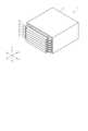
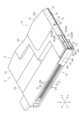
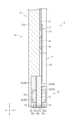
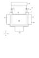
図1は、第1の実施形態に係る液体吐出ヘッド1の構成を模式的に示す斜視図であり、図2は、液体吐出ヘッド1に用いられるヘッド装置5を複数重ねて配置した構成の一例を示す側面図である。図3乃至図6は、ヘッド装置5の構成の全体及び要部を示しており、図3及び図5が斜視図であり、図4及び図6が側面図である。図7はヘッド装置5の液体吐出部10の構成を示す断面図である。図8は、ヘッド装置に用いられる冷却装置13の構成であって、特に、冷却板51の側面を示す説明図である。図9は、液体吐出ヘッド1が用いられる液体吐出装置100の構成を模式的に示す説明図である。図10は、液体吐出部10内を流れる温度分布の一例を示す説明図である。 FIG. 1 is a perspective view schematically showing the configuration of a
なお、図中、X、Y、Zは互いに直交する3方向を示し、アクチュエータ21の長手方向に沿った方向をX方向、アクチュエータ21の溝21aの長手方向に沿った方向をY方向、アクチュエータ21及びノズルプレート24の対向方向に沿った方向をZ方向として、以下説明する。また、各図において、説明の便宜上、適宜構成を拡大、縮小又は省略して示す。 In the drawing, X, Y, and Z indicate three directions orthogonal to each other. and the direction along which the
図1及び図2に示すように、液体吐出ヘッド1は、例えば、外郭ケース4と、外郭ケース4に収容される複数のヘッド装置5と、を備えている。なお、図2においては、外郭ケース4及び一部のヘッド装置5を省略して示す。 As shown in FIGS. 1 and 2 , the
例えば、液体吐出ヘッド1は、図9に示すインクジェット記録装置などの液体吐出装置100に設けられる。液体吐出ヘッド1は、液体吐出装置100に設けられた液体収容部としての供給タンク132を含む循環装置2に接続され、供給タンク132との間でインクを循環させる循環型のヘッドである。 For example, the
図2乃至図6に示すように、ヘッド装置5は、液体吐出部10と、ベースプレート11と、回路基板12と、冷却装置13と、を備えている。例えば、ヘッド装置5は、液体吐出部10、ベースプレート11、回路基板12及び冷却装置13が一体に組み立てられる。また、例えば、冷却装置13の後述する冷却板は、隣り合うヘッド装置5の液体吐出部10の後述する流路カバー23の第1流路カバー23Aと接触する。ヘッド装置5は、例えばシェアモードシェアウォール方式のヘッドである。例えば、図2に示すように、複数のヘッド装置5は、隣り合うヘッド装置5と積層して配置される。ヘッド装置5は、液体吐出ヘッド1として構成され、液体吐出装置100に設けられたときに、例えば液体吐出部10の後述するノズル24aが重力方向で下方に向く姿勢で配置される。 As shown in FIGS. 2 to 6, the
図3乃至図6に示すように、液体吐出部10は、アクチュエータ21と、アクチュエータ21の両主面を覆う一対のカバープレート22と、アクチュエータ21及びカバープレート22の両主面を覆う一対の流路カバー23と、ノズルプレート24と、を備える。なお、図3及び図4においては、ノズルプレート24を省略して示す。 As shown in FIGS. 3 to 6, the
アクチュエータ21は、一方向に長い板状に形成される。アクチュエータ21は、例えば一対の圧電部材が積層された積層圧電体で板状に構成されている。圧電部材として例えばPZT(チタン酸ジルコン酸鉛)が用いられる。一対の圧電部材は分極されている。 The
図5乃至図7に示すように、アクチュエータ21のノズルプレート24に対向する端部は、複数の溝21aと、複数の壁状の駆動素子部21bと、電極21cと、を有する。アクチュエータ21の端部は、X方向であるアクチュエータ21の長手方向で複数の溝21a及び駆動素子部21bが交互に並んで配される櫛歯状に構成される。即ち、アクチュエータ21のノズルプレート24側の端面に複数の駆動素子部21bが形成され、この複数の駆動素子部21bがX方向に離間して隣接することで、隣接する駆動素子部21bの間にそれぞれ溝21aが構成される。 As shown in FIGS. 5 to 7, the end portion of the
図7に示すように、電極21cは、各溝21aの内壁に形成される。例えば、各電極21cは、アクチュエータ21上の駆動素子部21bまで配線されている。各電極21cは、例えば、複数の回路基板12の後述するフレキシブル配線基板42を介してドライバIC43に電気的に接続されている。 As shown in FIG. 7,
一対のカバープレート22は、アクチュエータ21の長手方向と直交する方向、且つ、アクチュエータ21及びノズルプレート24の対向方向に直交する方向におけるアクチュエータ21の主面を覆う。即ち、一対のカバープレート22は、Y方向におけるアクチュエータ21の主面を覆う。 A pair of
図5乃至図7に示すように、カバープレート22は、Y方向において対向するアクチュエータ21に設けられた溝21aと同じ形状に形成された切欠22aを複数有する。一対のカバープレート22のうち一方は、溝21a内のY方向に沿った液体の流れ方向における一次側のアクチュエータ21の主面に設けられる第1カバープレート22Aを形成し、他方は溝21a内のY方向に沿った液体の流れ方向における二次側のアクチュエータ21の主面に設けられる第2カバープレート22Bを形成する。 As shown in FIGS. 5 to 7, the
複数の切欠22aは、アクチュエータ21に設けられた複数の溝21aと、溝21aの並び方向で一つ置きに対向する。即ち、カバープレート22は、複数の溝21aのうち、一つ置きの複数の溝21aのY方向の開口を切欠22aにより開放するとともに、一つ置きの他の複数の溝21aのY方向の開口を切欠22aが設けられていない領域により閉塞する。 The plurality of
換言すると、図7に示すように、アクチュエータ21及びカバープレート22は、溝21aのY方向の両端の開口が一対のカバープレート22によって閉塞された複数の空気室C1と、一対のカバープレート22の切欠22aによって溝21aのY方向の両端の開口が開放する複数の圧力室C2と、を構成する。そして、これら空気室C1及び圧力室C2は、交互にX方向に沿って並列に配置される。 In other words, as shown in FIG. 7, the
図3乃至図6に示すように、流路カバー23は、板状に形成される。例えば、流路カバー23は、アクチュエータ21及びカバープレート22と対向する面の一部が窪む。一対の流路カバー23は、Y方向におけるアクチュエータ21及びカバープレート22の外面を覆う。 As shown in FIGS. 3 to 6, the channel cover 23 is formed like a plate. For example, the channel cover 23 has a recessed part of the surface facing the
一対の流路カバー23のうち一方は、溝21a内のY方向に沿った液体の流れ方向における一次側のアクチュエータ21の主面及びカバープレート22を覆う第1流路カバー23Aを形成する。一対の流路カバー23のうち他方は、溝21a内のY方向に沿った液体の流れ方向における二次側のアクチュエータ21の主面及びカバープレート22を覆う第2流路カバー23Bを形成する。 One of the pair of channel covers 23 forms a first channel cover 23A that covers the main surface of the
図5及び図6に示すように、第1流路カバー23Aは、アクチュエータ21を覆う第1カバープレート22Aとの間に、圧力室C2に連通する第1共通室C3を形成する。第1共通室C3は、X方向に延び、全ての圧力室C2と流体的に接続される。第1共通室C3は、ベースプレート11の後述する流入管部31に連通する。第1共通室C3は、流入管部31及び複数の圧力室C2を連通する流入路を構成する。 As shown in FIGS. 5 and 6, the first flow path cover 23A and the first cover plate 22A covering the
具体例として、第1共通室C3は、長手方向の両端部において、ベースプレート11に設けられた一対の流入管部31に連通する。また、第1共通室C3は、複数の圧力室C2の一次側に配置され、複数の圧力室C2に、一対の流入管部31から流入した液体を供給する。 As a specific example, the first common chamber C3 communicates with a pair of
第2流路カバー23Bは、アクチュエータ21を覆う第2カバープレート22Bとの間に、圧力室C2に連通する第2共通室C4を形成する。第2共通室C4は、X方向に延び、全ての圧力室C2と流体的に接続される。第2共通室C4は、ベースプレート11の後述する流出管部32に連通する。第2共通室C4は、複数の圧力室C2及び流出管部32を連通する流出路を構成する。 The second flow path cover 23B forms a second common chamber C4 communicating with the pressure chamber C2 between itself and the second cover plate 22B covering the
具体例として、第2共通室C4は、長手方向の両端部において、ベースプレート11に設けられた一対の流出管部32に連通する。また、第2共通室C4は、複数の圧力室C2の二次側に配置され、複数の圧力室C2から流出した液体を一対の流出管部32へ排出する。 As a specific example, the second common chamber C4 communicates with a pair of
図5乃至図7に示すように、ノズルプレート24は、一方向に長い板状に構成される。ノズルプレート24は、例えば、圧力室C2に対向して、X方向に並列配置される複数のノズル24aを有する。ノズルプレート24は、ノズル24aが複数配列されて構成されるノズル列を、一列または複数列備える。各ノズル24aは、ノズルプレート24の両主面間を貫通する貫通孔である。 As shown in FIGS. 5 to 7, the
図3乃至図6に示すように、ベースプレート11は、樹脂やアルミ合金などの材料で板状に構成されている。ベースプレート11は、液体吐出部10、回路基板12及び冷却装置13を保持する。 As shown in FIGS. 3 to 6, the
本実施形態において、ベースプレート11は、一対の第1ベースパーツ11aと、一対の第2ベースパーツ11bと、一対の第3ベースパーツ11cと、一対の第4ベースパーツ11dと、を備える。ベースプレート11は、ベースパーツ11a、11b、11c、11dが連結された一対の板状部材11Aにより構成される。なお、例えば、ベースプレート11は、第3ベースパーツ11c及び第4ベースパーツ11dが、それぞれ、一対でなく、一つの部材により構成されることで、一対の第1ベースパーツ11a、一対の第2ベースパーツ11b、一つの第3ベースパーツ11c及び一つのベースパーツ11dを連結することで、一つの部材に構成されていてもよい。 In this embodiment, the
ベースプレート11の一方の主面には、回路基板12が設けられる。また、ベースプレート11の回路基板12が設けられる領域には、冷却装置13が設けられる。具体例として、ベースプレート11を構成する一対の板状部材11Aは、X方向に離間して設けられ、この一対の板状部材11Aの間に冷却装置13の後述する冷却板51が設けられる。 A
また、図3及び図4に示すように、ベースプレート11は、液体吐出部10の一次側に接続される流入管部31と、液体吐出部10の二次側に接続される流出管部32と、を備える。具体例として、流入管部31及び流出管部32は、それぞれ一対設けられる。流入管部31及び流出管部32は、隣接して設けられる。 3 and 4, the
本実施形態においては、一つの板状部材11Aに、一つの流入管部31及び一つの流出管部32が一体に設けられ、このような流入管部31及び流出管部32がそれぞれ一対設けられる。そして、一対の流出管部32は、一対の流入管部31よりも冷却装置13の冷却板51側に配置される。 In this embodiment, one
図3及び図4に示すように、流入管部31は、ベースパーツ11a、11b、11c、11dを連結する方向、換言すると、Z方向にベースパーツ11a、11b、11c、11dを貫通する孔で構成される1本の流入流路31aと、第1ベースパーツ11aに設けられる第1供給管31bと、を有する。 As shown in FIGS. 3 and 4, the
流入流路31aは、例えば、液体の流れ方向に直交する流路断面の形状が円形であり、流路断面積が一定に構成されている。流入流路31aは、一次側が第1供給管31bに接続され、二次側が液体吐出部10に形成される第1共通室C3に連通する。第1供給管31bは、例えば、循環装置2の接続流路133を介して供給タンク132に接続される。 The
図3及び図4に示すように、流出管部32は、Z方向にベースパーツ11a、11b、11c、11dを貫通する孔で構成される流出流路32aと、第1ベースパーツ11aに設けられる第1排出管32bと、を有する。 As shown in FIGS. 3 and 4, the
流出流路32aは、例えば、液体の流れ方向に直交する流路断面の形状が円形であり、流路断面積が一定に構成されている。流出流路32aは、一つの孔により構成されていても、複数の孔により構成される複数の流路により形成されていても良い。流出流路32aは、二次側が第1排出管32bに接続され、一次側が液体吐出部10に形成される第2共通室C4に連通する。第1排出管32bは、例えば、循環装置2の接続流路133を介して供給タンク132に接続される。 The
図2、図5及び図6に示すように、回路基板12は、制御基板41と、制御基板41に設けられた複数のフレキシブル配線基板42と、フレキシブル配線基板42のそれぞれに設けられたドライバIC43と、を備える。制御基板41は、例えば、矩形の板状である。制御基板41は、ベースプレート11の一方の主面であって、且つ、冷却装置13の冷却板51が設けられる領域に配置される。 As shown in FIGS. 2, 5, and 6, the
フレキシブル配線基板42は、X方向に複数が並列に配置される。フレキシブル配線基板42は、一端が制御基板41に、他端側がアクチュエータ21の複数の電極21cに接続される。ドライバIC43は、フレキシブル配線基板42のY方向でベースプレート11と対向する側の主面に実装される。ドライバIC43は、例えば、高い熱伝導性を有するグリスやシート等を介して冷却装置13の冷却板51に接して配置される。ドライバIC43は、フレキシブル配線基板42を介して、制御基板41上の配線及び電極21cに電気的に接続される。 A plurality of
図3乃至図6、図8に示すように、冷却装置13は、冷却板51と、冷却流路52と、冷却流路52の一次側の端部に設けられた第2供給管53と、冷却流路52の二次側の端部に設けられた第2排出管54と、冷却液供給回路55と、を備える。冷却装置13は、例えば、冷却液として水を用いて冷却板51と接する部材、本実施形態においては、制御基板41の実装品、ドライバIC43、及び、液体吐出部10の一部を冷却する。 As shown in FIGS. 3 to 6 and 8, the
冷却板51は、例えば、アルミニウム材料等の熱伝導性に優れた金属材料で形成される。冷却板51は、例えば、矩形状に形成される。冷却板51は、冷却する構成品と接触する。具体例として、冷却板51は、例えば、制御基板41の実装品やドライバIC43と接触するとともに、冷却流路52が形成される基部51aと、液体吐出部10の一部と接触する第1接触部51bと、流出管部32と接触する第2接触部51cと、を有する。例えば、基部51aは、ベースプレート11に配置されたときに、制御基板41に実装された発熱する電子部品及びドライバIC43と対向できる形状に形成される。 The cooling
第1接触部51bは、液体吐出部10の少なくとも最も液体が高温となる位置を含む外面の一部に接触する。具体例として、第1接触部51bは、少なくとも流入管部31から最も遠い位置を含む第2流路カバー23BのX方向における所定の領域の外面に接触する。ここで、第2流路カバー23BのX方向における所定の領域の外面とは、第2流路カバー23Bの外面のうち、X方向における比較的液体が高温となる一部の領域を意味し、第2流路カバー23BのX方向における外面の全領域は除かれる。 The
具体的に説明すると、ヘッド装置5の電極21cに駆動電圧を印加し、駆動素子部21bを駆動させると駆動素子部21b及び電極21cが発熱し、圧力室C2を通過する液体が加熱される。このため、液体吐出部10内の液体の温度は、流入管部31から遠くなるほど高くなる。 Specifically, when a driving voltage is applied to the
具体例を説明すると、本実施形態のヘッド装置5によれば、一対の流入管部31が第1共通室C3の長手方向で両端部に設けられる。このため、図10に示すように、液体吐出部10内の液体の温度は、液体吐出部10の長手方向で両端が低温となり、そして、中央が高温となる。また、液体吐出部10内の液体の温度は、液体吐出部10の短手方向で第1共通室C3側が低温となり、そして、圧力室C2で加熱され、第2共通室C4側が高温となる。 As a specific example, according to the
よって、本実施形態に係るヘッド装置5において、液体吐出部10内の液体の温度は、第2共通室C4の長手方向で中央が最も温度が高くなる。 Therefore, in the
このため、図3乃至図6に示すように、具体例として、第1接触部51bは、Z方向で冷却板51の基部51aと対向するアクチュエータ21の端面のX方向で中央部の領域、並びに、第2流路カバー23BのZ方向で冷却板51の基部51aと対向する外面のX方向で中央部と接触する。加えて、第1接触部51bは、Y方向で対向する第2流路カバー23Bの外面のX方向で中央部の領域と接触する。また、例えば、第1接触部51bは、隣り合うヘッド装置5の第1流路カバー23Aの外面と接触する。 For this reason, as shown in FIGS. 3 to 6, as a specific example, the
第2接触部51cは、流出管部32と同数、本実施形態においては一対設けられる。第2接触部51cは、流出管部32の外面の一部に接触する。具体例として、図3乃至図6に示すように、第2接触部51cは、流出管部32のY方向で第2流路カバー23Bが設けられる側であって、且つ、Z方向で中央側、更に具体例として、第2ベースパーツ11b及び第3ベースパーツ11cの一部の外面に接触する。 The
冷却流路52は、冷却板51の基部51a内に設けられた孔により形成される。例えば、冷却流路52の一次側及び二次側の端部は、冷却板51がベースプレート11に配置された姿勢で、冷却板51のY方向で液体吐出部10と対向する端部とは反対側の端部であって、且つ、X方向における両端側に配置される。また、冷却流路52は、少なくとも基部51aの第1接触部51b及び第2接触部51cと隣接する位置の一部に配置される。 The cooling
例えば、冷却流路52は、一次側の端部から一方の第2接触部51cに隣接してZ方向に延び、第1接触部51bに隣接する基部51aの端部においてX方向に延び、そして、他方の第2接触部51cに隣接して二次側の端部に向かってZ方向に延びる。なお、冷却流路52の形状や配置は、適宜設定される。 For example, the cooling
第2供給管53及び第2排出管54は、基部51aに固定され、冷却流路52の一端及び他端に接続される。第2供給管53及び第2排出管54は、例えば、冷却液供給回路55に接続される。冷却液供給回路55は、例えば、冷却液を供給する配管やチューブ等の流路及びポンプを有する。 The
次に、液体吐出ヘッド1を有する液体吐出装置100について、図9を用いて説明する。図9に示すように、液体吐出装置100は、筐体111と、媒体供給部112と、画像形成部113と、媒体排出部114と、支持装置である搬送装置115と、制御部116と、を備える。 Next, a
液体吐出装置100は、例えば、インクジェットプリンタである。液体吐出装置100は、媒体供給部112から画像形成部113を通って媒体排出部114に至る所定の搬送路A1に沿って、吐出対象物である記録媒体として例えば用紙Pを搬送する。そして、液体吐出装置100は、液体としてインクを吐出することで、搬送した用紙Pに画像形成処理を行う。 The
媒体供給部112は複数の給紙カセット112aを備える。媒体排出部114は、排紙トレイ114aを備える。画像形成部113は、用紙を支持する支持部117と、支持部117の上方に対向配置された複数のヘッドユニット130と、を備える。 The
支持部117は、画像形成を行う所定領域にループ状に備えられる搬送ベルト118と、搬送ベルト118を裏側から支持する支持プレート119と、搬送ベルト118の裏側に備えられた複数のベルトローラ120と、を備える。 The
ヘッドユニット130は、複数の液体吐出ヘッドである液体吐出ヘッド1と、循環装置2と、を備える。循環装置2は、例えば、各液体吐出ヘッド1上にそれぞれ搭載された液体タンクとしての複数の供給タンク132と、液体吐出ヘッド1と供給タンク132とを接続する接続流路133と、循環部である循環ポンプ134と、を備える。ヘッドユニット130は、液体を循環させる循環型のヘッドユニットである。 The
本実施形態において、液体吐出ヘッド1としてシアン、マゼンダ、イエロー、ブラックの4色のインクを液体として吐出する液体吐出ヘッド1C,1M,1Y,1Bと、これらの各色のインクをそれぞれ収容する供給タンク132として、供給タンク132C,132M,132Y,132Bと、を備える。供給タンク132は接続流路133によって液体吐出ヘッド1に接続される。接続流路133は、液体吐出ヘッド1の流入管部31に接続される供給流路133aと、液体吐出ヘッド1の流出管部32に接続される回収流路133bと、を備える。 In the present embodiment, liquid ejection heads 1C, 1M, 1Y, and 1B for ejecting inks of four colors, cyan, magenta, yellow, and black, as liquid ejection heads 1, and supply tanks containing inks of these colors, respectively. 132 includes
また、供給タンク132には、図示しないポンプなどの負圧制御装置が連結されている。そして、液体吐出ヘッド1と供給タンク132との水頭値に対応して、負圧制御装置により供給タンク132内を負圧制御することで、液体吐出ヘッド1の各ノズル24aに供給された液体は所定形状のメニスカスに形成される。 A negative pressure control device such as a pump (not shown) is connected to the
循環ポンプ134は、例えば圧電ポンプで構成される送液ポンプである。循環ポンプ134は、供給流路133aに設けられている。循環ポンプ134は、配線により制御部116に接続され、CPU(Central Processing Unit)116aの制御によって制御可能に構成されている。循環ポンプ134は、液体吐出ヘッド1と供給タンク132を含む循環流路で液体を循環させる。 The
搬送装置115は、媒体供給部112の給紙カセット112aから画像形成部113を通って媒体排出部114の排紙トレイ114aに至る搬送路A1に沿って、用紙Pを搬送する。搬送装置115は、搬送路A1に沿って配置される複数のガイドプレート対121a~121hと、複数の搬送用ローラ122a~122hと、を備えている。搬送装置115は、用紙Pを液体吐出ヘッド1に相対移動可能に支持する。 The
制御部116は、プロセッサの一例としてのCPU(中央制御装置)116aと、各種のプログラムなどを記憶するROM(Read Only Memory)と、各種の可変データや画像データなどを一時的に記憶するRAM(Random Access Memory)と、外部からのデータの入力及び外部へのデータの出力をするインターフェイス部と、を備える。 The
このように構成された液体吐出ヘッド1及び液体吐出装置100によれば、循環装置2の循環ポンプ134が駆動されることで、液体は、供給タンク132及び接続流路133から、流入管部31及び第1共通室C3を通って複数の圧力室C2へ至る。 According to the
ノズル24aから液体を吐出する場合には、制御部116は、ドライバIC43を制御し、駆動素子部21bに駆動電圧を印加して、ノズル24aから液体を吐出する。具体例として、ドライバIC43は、駆動電圧をアクチュエータ21の複数の溝21aに設けられた電極21cに印加する。このとき、ドライバIC43は、駆動する圧力室C2内の電極21cと、両隣の空気室C1の電極21cに電位差を与える。すると、図7の一つの駆動素子部21bに示すように、アクチュエータ21を構成する一対の圧電材料が互いに逆向きに変形し、駆動素子部21bが屈曲変形する。ドライバIC43は、異なる方向の屈曲変形を交互に繰り返すことで、圧力室C2の容積を増減し、圧力室C2に対向するノズル24aから液体を液滴として吐出する。 When ejecting the liquid from the
また、ノズル24aから吐出されなかった液体は、圧力室C2から第2共通室C4、流出管部32及び接続流路133を通って供給タンク132に回収される。このように、液体吐出ヘッド1に供給される液体は、循環装置2及び液体吐出ヘッド1内を循環する。 Also, the liquid that has not been discharged from the
なお、電極21cに駆動電圧を印加し、駆動素子部21bを駆動させると、駆動素子部21b及び電極21cが発熱することから、圧力室C2を通過する液体が加熱される。しかしながら、本実施形態の液体吐出ヘッド1は、冷却装置13の冷却板51に、少なくとも液体吐出部10の流入管部31から最も遠い位置を含む外面の一部に接触する第1接触部51bを設けた。このため、冷却装置13によって第2共通室C4を構成する一部である第2流路カバー23Bの流入管部31から最も遠い位置を含む一部の領域が冷却されることから、第2共通室C4内の最も高い温度となる液体が冷却される。 When the driving
よって、複数の圧力室C2のうち流入管部31から遠い位置にある一部の圧力室C2内のノズルプレート24の表面である吐出面の液体が冷却されることになり、複数の吐出面における液体温度の最大値と最小値の差を低減できる。このように、液体吐出ヘッド1は、複数の圧力室C2の吐出面の液体の均熱化及び液体の温度の低減が可能となる。これにより、液体吐出ヘッド1は、複数の圧力室C2における吐出面の液体(インク)の温度のばらつきによる粘度差を抑制し、印字の高精細性が低下することを防止できる。 Therefore, the liquid on the ejection surface, which is the surface of the
また、液体吐出部10内で高温となる液体を冷却装置13で冷却することから、液体吐出ヘッド1を循環装置2に接続し、液体を循環させる液体吐出装置100においては、供給タンク132に戻る液体の温度を低減できる。加えて、液体吐出部10に接続される流出管部32に冷却板51の第2接触部51cを接触させることで、流出管部32内を流れ、供給タンク132に戻る液体を冷却することができる。このため、循環装置2によって液体を循環させた場合であっても、液体の温度が上昇することを抑制できる。 Further, since the liquid that reaches a high temperature in the
上述したように一実施形態に係る液体吐出ヘッド1及び液体吐出装置100によれば、液体吐出部10内の液体の均熱化することができる。即ち、液体吐出ヘッド1及び液体吐出装置100は、液体吐出部10内において液体の温度が比較的高くなる液体吐出部10の流入管部31から最も遠い位置を含む外面の一部を冷却装置13の冷却板51の一部を接触させて冷却する構成とした。これにより、液体吐出ヘッド1及び液体吐出装置100は、複数の吐出面において比較的温度が高くなる液体を冷却できることから、複数の圧力室C2の吐出面の液体の温度を均熱化可能、且つ、液体の温度を低減可能となる。 As described above, according to the
なお、本発明は上記実施形態そのままに限定されるものではなく、実施段階ではその要旨を逸脱しない範囲で構成要素を変形して具体化できる。 It should be noted that the present invention is not limited to the above-described embodiments as they are, and can be embodied by modifying constituent elements without departing from the scope of the present invention at the implementation stage.
上述した例では、液体吐出ヘッド1のヘッド装置5は、一対の流入管部31及び一対の流出管部32を有する構成を説明したがこれに限定されない。例えば、図11及び図12に示す他の実施形態に係る液体吐出ヘッド1のヘッド装置5Aのように、一つの流入管部31及び一つの流出管部32を有する構成としてもよい。このような構成のヘッド装置5Aとする場合には、冷却装置13の冷却板51に隣接して流出管部32を配置し、第2接触部51cを流出管部32に接触させる構成とする。また、一つの流入管部31とした場合には、第2流路カバー23Bの流入管部31から最も遠い端部において液体の温度が高くなることから、第2流路カバー23BのX方向で流入管部31側とは反対側の端部の外面に第1接触部51bを接触させる。また、図11及び図12に示すように、一つの流入管部31及び一つの流出管部32を隣接して配置するのではなく、液体吐出部10の長手方向で一方の端部に一つの流入管部31を、他方の端部に一つの流出管部32を設ける構成としてもよい。 In the above example, the
また、上述した例では、流入管部31及び流出管部32は、ベースプレート11により形成される構成を説明したがこれに限定されない。例えば、図11及び図12に示すように、流入管部31及び流出管部32は、それぞれ別体の管により形成されていてもよい。 Further, in the above-described example, the configuration in which the
また、上述した例では、冷却板51は、第1接触部51b及び第2接触部51cを有する構成を説明したがこれに限定されない。例えば、冷却板51は、第1接触部51bのみを有する構成としてもよい。また、上述した例では、第1接触部51bは、液体吐出部10のZ方向でノズルプレート24とは反対側の外面の一部及び液体吐出部10の第2共通室C4側のY方向の外面の一部に接触する構成を説明したがこれに限定されない。例えば、図13に示す他の実施形態に示す液体吐出ヘッド1のヘッド装置5Bのように、第1接触部51bは、液体吐出部10のZ方向でノズルプレート24とは反対側の外面の一部のみと接触する構成であってもよい。 In the above example, the cooling
また、例えば、上述した例では、液体吐出ヘッド1は、複数のヘッド装置5を有する構成としたがこれに限定されず、液体吐出ヘッド1は、ヘッド装置5を一つだけ備える構成であってもよい。 Further, for example, in the above-described example, the
以上説明した少なくともひとつの実施形態によれば、液体の均熱化が可能な液体吐出ヘッド及び液体吐出装置を提供できる。 According to at least one of the embodiments described above, it is possible to provide a liquid ejection head and a liquid ejection apparatus capable of equalizing the temperature of liquid.
本発明のいくつかの実施形態を説明したが、これらの実施形態は、例として提示したものであり、発明の範囲を限定することは意図していない。これら新規な実施形態は、その他の様々な形態で実施されることが可能であり、発明の要旨を逸脱しない範囲で、種々の省略、置き換え、変更を行うことができる。これら実施形態やその変形は、発明の範囲や要旨に含まれるとともに、特許請求の範囲に記載された発明とその均等の範囲に含まれる。
以下に、本願出願の当初の特許請求の範囲に記載された発明と同等の記載を付記する。
[1] 第1共通室、前記第1共通室に接続された複数の圧力室を構成するアクチュエータ、及び、前記複数の圧力室に接続された第2共通室を含む液体吐出部と、
前記第1共通室に液体を供給する流入管部と、
前記第2共通室から前記液体を排出する流出管部と、
前記液体吐出部の前記流入管部から前記液体の流れ方向で最も遠い位置を含む前記第2共通室の外面の一部又は前記流出管部の外面の一部に接触する冷却板、及び、前記冷却板に設けられ、冷却水が通過する冷却流路を含む冷却装置と、
を備える液体吐出ヘッド。
[2] 前記液体吐出部は、前記複数の圧力室の一次側に設けられ、前記第1共通室を形成する第1流路カバーと、前記複数の圧力室の二次側に設けられ、前記第2共通室を形成する第2流路カバーと、を有し、
前記冷却板は、前記第2流路カバーの前記冷却板と対向する外面の一部、並びに、前記第2流路カバー及び前記冷却板の対向する方向と直交する方向、且つ、前記アクチュエータの長手方向に直交する方向における前記第2流路カバーの外面の一部と接触する、[1]に記載の液体吐出ヘッド。
[3] 前記冷却板は、さらに、前記流出管部の外面の一部と接触する、[2]に記載の液体吐出ヘッド。
[4] 前記冷却板は、前記アクチュエータを駆動するドライバICと接触する[1]乃至[3]のいずれか一項に記載の液体吐出ヘッド。
[5] 前記液体吐出部、前記流入管部、前記流出管部及び前記冷却装置が一体に組み立てられたヘッド装置を複数有し、
前記冷却板は、隣り合う前記ヘッド装置の前記第1流路カバーと接触する、[2]又は[3]に記載の液体吐出ヘッド。
[6] 第1共通室、前記第1共通室に接続された複数の圧力室を構成するアクチュエータ、及び、前記複数の圧力室に接続された第2共通室を含む液体吐出部と、前記第1共通室に液体を供給する流入管部と、前記第2共通室から液体を排出する流出管部と、前記液体吐出部の前記流入管部から前記液体の流れ方向で最も遠い位置を含む前記第2共通室の外面の一部又は前記流出管部の外面の一部に接触する冷却板、及び、前記冷却板に設けられ、冷却水が通過する冷却流路を含む冷却装置と、を具備する液体吐出ヘッドと、
前記液体を吐出する対象物を支持する支持装置と、
を備える液体吐出装置。While several embodiments of the invention have been described, these embodiments have been presented by way of example and are not intended to limit the scope of the invention. These novel embodiments can be implemented in various other forms, and various omissions, replacements, and modifications can be made without departing from the scope of the invention. These embodiments and modifications thereof are included in the scope and gist of the invention, and are included in the scope of the invention described in the claims and equivalents thereof.
The description equivalent to the invention described in the original claims of the present application is added below.
[1] a liquid discharger including a first common chamber, an actuator forming a plurality of pressure chambers connected to the first common chamber, and a second common chamber connected to the plurality of pressure chambers;
an inflow pipe portion that supplies liquid to the first common chamber;
an outflow pipe section for discharging the liquid from the second common chamber;
a cooling plate in contact with a portion of the outer surface of the second common chamber including the farthest position in the flow direction of the liquid from the inflow pipe portion of the liquid discharge portion or a portion of the outer surface of the outflow pipe portion; a cooling device provided in the cooling plate and including a cooling channel through which the cooling water passes;
a liquid ejection head.
[2] The liquid discharge section is provided on the primary side of the plurality of pressure chambers, and is provided on the secondary side of the plurality of pressure chambers. a second flow path cover forming a second common chamber;
The cooling plate includes a portion of the outer surface of the second channel cover facing the cooling plate, a direction orthogonal to the facing direction of the second channel cover and the cooling plate, and a longitudinal direction of the actuator. The liquid ejection head according to [1], which contacts a portion of the outer surface of the second channel cover in a direction perpendicular to the direction.
[3] The liquid ejection head according to [2], wherein the cooling plate further contacts part of the outer surface of the outflow tube portion.
[4] The liquid ejection head according to any one of [1] to [3], wherein the cooling plate is in contact with a driver IC that drives the actuator.
[5] having a plurality of head devices in which the liquid discharge portion, the inflow pipe portion, the outflow pipe portion, and the cooling device are integrally assembled;
The liquid ejection head according to [2] or [3], wherein the cooling plate is in contact with the first channel cover of the adjacent head device.
[6] a first common chamber, an actuator forming a plurality of pressure chambers connected to the first common chamber, and a liquid ejection portion including a second common chamber connected to the plurality of pressure chambers; an inflow pipe portion for supplying liquid to one common chamber; an outflow pipe portion for discharging liquid from the second common chamber; a cooling plate that contacts a portion of the outer surface of the second common chamber or a portion of the outer surface of the outflow pipe portion; and a cooling device that is provided on the cooling plate and includes a cooling channel through which cooling water passes. a liquid ejection head that
a support device for supporting an object onto which the liquid is to be ejected;
A liquid ejection device comprising:
1…液体吐出ヘッド、2…循環装置、4…外郭ケース、5…ヘッド装置、10…液体吐出部、11…ベースプレート、11a…第1ベースパーツ、11a…ベースパーツ、11A…板状部材、11b…第2ベースパーツ、11b…ベースパーツ、11c…第3ベースパーツ、11c…ベースパーツ、11d…第4ベースパーツ、11d…ベースパーツ、12…回路基板、13…冷却装置、21…アクチュエータ、21a…溝、21b…駆動素子部、21c…電極、22…カバープレート、22A…第1カバープレート、22B…第2カバープレート、22a…切欠、23…流路カバー、23A…第1流路カバー、23B…第2流路カバー、24…ノズルプレート、24a…ノズル、31…流入管部、31a…流入流路、31b…第1供給管、32…流出管部、32a…流出流路、32b…第1排出管、41…制御基板、42…フレキシブル配線基板、43…ドライバIC、51…冷却板、51a…基部、51b…第1接触部、51c…第2接触部、52…冷却流路、53…第2供給管、54…第2排出管、55…冷却液供給回路、100…液体吐出装置、111…筐体、112…媒体供給部、112a…給紙カセット、113…画像形成部、114…媒体排出部、114a…排紙トレイ、115…搬送装置、116…制御部、117…支持部、118…搬送ベルト、119…支持プレート、120…ベルトローラ、130…ヘッドユニット、132…供給タンク、133…接続流路、133a…供給流路、133b…回収流路、134…循環ポンプ、C1…空気室、C2…圧力室、C3…第1共通室、C4…第2共通室、P…用紙。 DESCRIPTION OF
Claims (5)
Translated fromJapanese前記第1共通室に液体を供給する流入管部と、
前記第2共通室から前記液体を排出する流出管部と、
前記液体吐出部の前記流入管部から前記液体の流れ方向で最も遠い位置を含む前記第2共通室の外面の一部に接触するか、又は、前記液体吐出部の前記流入管部から前記液体の流れ方向で最も遠い位置を含む前記第2共通室の外面の一部及び前記流出管部の外面の一部に接触する冷却板、及び、前記冷却板に設けられ、冷却水が通過する冷却流路を含む冷却装置と、
を備え、
前記液体吐出部は、前記複数の圧力室の一次側に設けられ、前記第1共通室を形成する第1流路カバーと、前記複数の圧力室の二次側に設けられ、前記第2共通室を形成する第2流路カバーと、を有し、
前記冷却板は、前記第2流路カバーの前記冷却板と対向する外面の一部、並びに、前記第2流路カバー及び前記冷却板の対向する方向と直交する方向、且つ、前記アクチュエータの長手方向に直交する方向における前記第2流路カバーの外面の一部と接触する、液体吐出ヘッド。a first common chamber, an actuator forming a plurality of pressure chambers connected to the first common chamber, and a liquid ejection section including a second common chamber connected to the plurality of pressure chambers;
an inflow pipe portion that supplies liquid to the first common chamber;
an outflow pipe section for discharging the liquid from the second common chamber;
contact with a portion of the outer surface of the second common chamber including the farthest position in the flow direction of the liquid from the inflow pipe portion of the liquid discharge portion, or the liquid from the inflow pipe portion of the liquid discharge portion; A cooling plate that contactsa portion of the outer surface of the second common chamber including the farthest position in the flow direction and a portion of the outer surface of the outflow pipe portion, and a cooling plate provided on the cooling plate through which cooling water passes a cooling device including a flow path;
with
The liquid discharge section is provided on the primary side of the plurality of pressure chambers and includes a first flow path cover that forms the first common chamber, and the liquid discharge section is provided on the secondary side of the plurality of pressure chambers and includes the second common chamber. a second channel cover forming the chamber;
The cooling plate includes a portion of the outer surface of the second channel cover facing the cooling plate, a direction orthogonal to the facing direction of the second channel cover and the cooling plate, and a longitudinal direction of the actuator. A liquid ejection headthat contacts a portion of the outer surface of the second channel cover in a direction orthogonal to the direction .
前記冷却板は、隣り合う前記ヘッド装置の前記第1流路カバーと接触する、請求項1又は請求項2に記載の液体吐出ヘッド。a plurality of head devices in which the liquid discharge portion, the inflow pipe portion, the outflow pipe portion, and the cooling device are integrally assembled;
3. The liquid ejection head according toclaim 1 , wherein said cooling plate is in contact with said first channel cover of said adjacent head device.
前記液体を吐出する対象物を支持する支持装置と、
を備え、
前記液体吐出部は、前記複数の圧力室の一次側に設けられ、前記第1共通室を形成する第1流路カバーと、前記複数の圧力室の二次側に設けられ、前記第2共通室を形成する第2流路カバーと、を有し、
前記冷却板は、前記第2流路カバーの前記冷却板と対向する外面の一部、並びに、前記第2流路カバー及び前記冷却板の対向する方向と直交する方向、且つ、前記アクチュエータの長手方向に直交する方向における前記第2流路カバーの外面の一部と接触する、液体吐出装置。a first common chamber, an actuator forming a plurality of pressure chambers connected to the first common chamber, a liquid ejection section including a second common chamber connected to the plurality of pressure chambers, and the first common chamber an inflow pipe portion for supplying liquid to the second common chamber; an outflow pipe portion for discharging liquid from the second common chamber;A part of the outer surface of the second common chamber that contacts a part of the outer surface of the chamber or includes a position farthest in the flow direction of the liquid from the inflow pipe part of the liquid discharge part and the outflow pipe part a liquid ejection head comprising: a cooling plate in contact with a portion of an outer surface; and a cooling device provided in the cooling plate and including a cooling channel through which cooling water passes;
a support device for supporting an object onto which the liquid is to be ejected;
with
The liquid discharge section is provided on the primary side of the plurality of pressure chambers and includes a first flow path cover that forms the first common chamber, and the liquid discharge section is provided on the secondary side of the plurality of pressure chambers and includes the second common chamber. a second channel cover forming the chamber;
The cooling plate includes a portion of the outer surface of the second channel cover facing the cooling plate, a direction orthogonal to the facing direction of the second channel cover and the cooling plate, and a longitudinal direction of the actuator. A liquid ejection devicethat contacts a portion of the outer surface of the second flow path cover in a direction orthogonal to the direction .
Priority Applications (2)
| Application Number | Priority Date | Filing Date | Title |
|---|---|---|---|
| JP2019093926AJP7292972B2 (en) | 2019-05-17 | 2019-05-17 | Liquid ejection head and liquid ejection device |
| CN201921749927.XUCN211617044U (en) | 2019-05-17 | 2019-10-18 | Liquid discharge head and liquid discharge device |
Applications Claiming Priority (1)
| Application Number | Priority Date | Filing Date | Title |
|---|---|---|---|
| JP2019093926AJP7292972B2 (en) | 2019-05-17 | 2019-05-17 | Liquid ejection head and liquid ejection device |
Publications (2)
| Publication Number | Publication Date |
|---|---|
| JP2020185778A JP2020185778A (en) | 2020-11-19 |
| JP7292972B2true JP7292972B2 (en) | 2023-06-19 |
Family
ID=72623783
Family Applications (1)
| Application Number | Title | Priority Date | Filing Date |
|---|---|---|---|
| JP2019093926AActiveJP7292972B2 (en) | 2019-05-17 | 2019-05-17 | Liquid ejection head and liquid ejection device |
Country Status (2)
| Country | Link |
|---|---|
| JP (1) | JP7292972B2 (en) |
| CN (1) | CN211617044U (en) |
Families Citing this family (3)
| Publication number | Priority date | Publication date | Assignee | Title |
|---|---|---|---|---|
| CN116458129A (en) | 2020-11-06 | 2023-07-18 | 松下电器(美国)知识产权公司 | Communication device and communication method |
| JP2023047194A (en)* | 2021-09-24 | 2023-04-05 | 株式会社Screenホールディングス | inkjet head |
| JP2023103780A (en)* | 2022-01-14 | 2023-07-27 | 東芝テック株式会社 | liquid ejection head |
Citations (2)
| Publication number | Priority date | Publication date | Assignee | Title |
|---|---|---|---|---|
| JP2010089402A (en) | 2008-10-09 | 2010-04-22 | Seiko Epson Corp | Liquid jetting head and liquid jetting apparatus |
| JP2019064148A (en) | 2017-09-29 | 2019-04-25 | ブラザー工業株式会社 | Head unit and liquid discharge device |
- 2019
- 2019-05-17JPJP2019093926Apatent/JP7292972B2/enactiveActive
- 2019-10-18CNCN201921749927.XUpatent/CN211617044U/ennot_activeExpired - Fee Related
Patent Citations (2)
| Publication number | Priority date | Publication date | Assignee | Title |
|---|---|---|---|---|
| JP2010089402A (en) | 2008-10-09 | 2010-04-22 | Seiko Epson Corp | Liquid jetting head and liquid jetting apparatus |
| JP2019064148A (en) | 2017-09-29 | 2019-04-25 | ブラザー工業株式会社 | Head unit and liquid discharge device |
Also Published As
| Publication number | Publication date |
|---|---|
| CN211617044U (en) | 2020-10-02 |
| JP2020185778A (en) | 2020-11-19 |
Similar Documents
| Publication | Publication Date | Title |
|---|---|---|
| JP7366586B2 (en) | Liquid ejection head and liquid ejection device | |
| US10730306B2 (en) | Liquid discharge head | |
| JP7292972B2 (en) | Liquid ejection head and liquid ejection device | |
| US8662642B2 (en) | Liquid ejection head | |
| JP2023045594A (en) | liquid ejection head | |
| JP7461173B2 (en) | Liquid ejection head and liquid ejection device | |
| JP7110126B2 (en) | Inkjet head, inkjet device, and method for manufacturing inkjet head | |
| JP7055656B2 (en) | Liquid discharge head and liquid discharge device | |
| US20240009997A1 (en) | Liquid ejection head | |
| JP7577550B2 (en) | Liquid ejection head and liquid ejection device | |
| JP2024015797A (en) | liquid discharge head | |
| JP7286403B2 (en) | LIQUID EJECTION HEAD, LIQUID EJECTION DEVICE, AND RECORDING DEVICE | |
| US20240308217A1 (en) | Liquid ejection head | |
| JP2021123064A (en) | Liquid discharge head and device that discharges liquid | |
| JP7707007B2 (en) | Liquid ejection head | |
| JP7374681B2 (en) | Liquid ejection head and liquid ejection device | |
| JP2013132769A (en) | Printer | |
| JP7654517B2 (en) | Liquid ejection head | |
| JP7189311B2 (en) | Liquid ejection head and liquid ejection device | |
| JP6176004B2 (en) | Liquid ejection device | |
| US20250050638A1 (en) | Liquid ejection head and liquid ejection device | |
| JP2011235481A (en) | Liquid ejection apparatus | |
| JP2023077729A (en) | liquid ejection head | |
| JP2023103780A (en) | liquid ejection head | |
| JP2024146601A (en) | HEAD ASSEMBLY, METHOD EXECUTED BY A CONTROLLER CONNECTED TO THE HEAD ASSEMBLY, AND SYSTEM COMPRISING THE HEAD ASSEMBLY - Patent application |
Legal Events
| Date | Code | Title | Description |
|---|---|---|---|
| A621 | Written request for application examination | Free format text:JAPANESE INTERMEDIATE CODE: A621 Effective date:20220510 | |
| RD02 | Notification of acceptance of power of attorney | Free format text:JAPANESE INTERMEDIATE CODE: A7422 Effective date:20230104 | |
| A977 | Report on retrieval | Free format text:JAPANESE INTERMEDIATE CODE: A971007 Effective date:20230214 | |
| A131 | Notification of reasons for refusal | Free format text:JAPANESE INTERMEDIATE CODE: A131 Effective date:20230228 | |
| A521 | Request for written amendment filed | Free format text:JAPANESE INTERMEDIATE CODE: A523 Effective date:20230425 | |
| TRDD | Decision of grant or rejection written | ||
| A01 | Written decision to grant a patent or to grant a registration (utility model) | Free format text:JAPANESE INTERMEDIATE CODE: A01 Effective date:20230509 | |
| A61 | First payment of annual fees (during grant procedure) | Free format text:JAPANESE INTERMEDIATE CODE: A61 Effective date:20230607 | |
| R150 | Certificate of patent or registration of utility model | Ref document number:7292972 Country of ref document:JP Free format text:JAPANESE INTERMEDIATE CODE: R150 | |
| S111 | Request for change of ownership or part of ownership | Free format text:JAPANESE INTERMEDIATE CODE: R313111 | |
| R350 | Written notification of registration of transfer | Free format text:JAPANESE INTERMEDIATE CODE: R350 |