Movatterモバイル変換


[0]ホーム

URL:


JP7290796B2 - Suction device, information processing method, and program - Google Patents

Suction device, information processing method, and program
Download PDF

Info

Publication number
JP7290796B2
JP7290796B2JP2022508092AJP2022508092AJP7290796B2JP 7290796 B2JP7290796 B2JP 7290796B2JP 2022508092 AJP2022508092 AJP 2022508092AJP 2022508092 AJP2022508092 AJP 2022508092AJP 7290796 B2JP7290796 B2JP 7290796B2
Authority
JP
Japan
Prior art keywords
compression
suction device
heating
unit
base material
Prior art date
Legal status (The legal status is an assumption and is not a legal conclusion. Google has not performed a legal analysis and makes no representation as to the accuracy of the status listed.)
Active
Application number
JP2022508092A
Other languages
Japanese (ja)
Other versions
JPWO2021186880A1 (en
Inventor
浩 岡本
吉高 松本
貴文 泉屋
正実 川邊
尚弘 時津
裕介 七崎
Current Assignee (The listed assignees may be inaccurate. Google has not performed a legal analysis and makes no representation or warranty as to the accuracy of the list.)
Japan Tobacco Inc
Original Assignee
Japan Tobacco Inc
Priority date (The priority date is an assumption and is not a legal conclusion. Google has not performed a legal analysis and makes no representation as to the accuracy of the date listed.)
Filing date
Publication date
Application filed by Japan Tobacco IncfiledCriticalJapan Tobacco Inc
Publication of JPWO2021186880A1publicationCriticalpatent/JPWO2021186880A1/ja
Application grantedgrantedCritical
Publication of JP7290796B2publicationCriticalpatent/JP7290796B2/en
Activelegal-statusCriticalCurrent
Anticipated expirationlegal-statusCritical

Links

Images

Classifications

Description

Translated fromJapanese

本発明は、吸引装置、情報処理方法、及びプログラムに関する。 The present invention relates to a suction device, an information processing method, and a program.

電子タバコ及びネブライザ等の、ユーザに吸引される物質を生成する吸引装置が広く普及している。例えば、吸引装置は、エアロゾルを生成するためのエアロゾル源、及び生成されたエアロゾルに香味成分を付与するための香味源等を含む基材を用いて、香味成分が付与されたエアロゾルを生成する。ユーザは、吸引装置により生成された、香味成分が付与されたエアロゾルを吸引することで、香味を味わうことができる。 Inhalation devices, such as electronic cigarettes and nebulizers, that produce a substance that is inhaled by the user are widespread. For example, the suction device uses a base material including an aerosol source for generating an aerosol and a flavor source for imparting a flavor component to the generated aerosol to generate an aerosol imparted with a flavor component. A user can enjoy the flavor by inhaling the flavor component-applied aerosol generated by the suction device.

ユーザによる吸引体験の質の向上を目的として、吸引装置の様々な構造が検討されている。例えば、下記特許文献1では、吸引装置に設けられた挿入孔から内部空間に挿入されたスティック型の基材を加熱することでエアロゾルを生成する吸引装置に関し、挿入孔を狭めてスティック型の基材を締める構造が開示されている。 Various constructions of suction devices have been considered with the aim of improving the quality of the suction experience by the user. For example,Patent Document 1 below relates to a suction device that generates an aerosol by heating a stick-shaped base material inserted into an internal space through an insertion hole provided in the suction device. A structure for tightening the material is disclosed.

国際公開第2019/081602号WO2019/081602

しかし、上記特許文献1に記載の技術は、挿入孔から吸引装置の内部空間に挿入されたスティック型の基材の位置を適正化することが目的とされているので、かかる技術がユーザの吸引体験の質の向上に直接的に繋がるとは言い難い。 However, the technique described inPatent Document 1 aims to optimize the position of the stick-shaped substrate inserted into the internal space of the suction device through the insertion hole. It is difficult to say that it directly leads to the improvement of the quality of experience.

そこで、本発明は、上記問題に鑑みてなされたものであり、本発明の目的とするところは、ユーザの吸引体験の質をより向上させることが可能な仕組みを提供することにある。 Accordingly, the present invention has been made in view of the above problems, and an object of the present invention is to provide a mechanism capable of further improving the quality of a user's sucking experience.

上記課題を解決するために、本発明のある観点によれば、基材を加熱することでユーザに吸引されるエアロゾルを生成する吸引装置であって、前記吸引装置に形成された内部空間に挿入された前記基材の内部に挿入され、前記基材を加熱する加熱部と、前記基材のうち前記加熱部により加熱される部分である被加熱部分を外周から前記加熱部の方向へ圧縮する圧縮部と、前記加熱部による加熱及び前記圧縮部による圧縮の、一方の開始に基づいて他方を開始する制御部と、を備える吸引装置が提供される。 In order to solve the above problems, according to one aspect of the present invention, there is provided a suction device that heats a substrate to generate an aerosol that is sucked by a user, and is inserted into an internal space formed in the suction device. a heating unit inserted into the base material to heat the base material; A suction device is provided comprising a compressing section and a control section for initiating one of heating by the heating section and compressing by the compressing section upon initiation of the other.

前記制御部は、前記加熱部による加熱の開始タイミングと前記圧縮部による圧縮の開始タイミングとを一致又は略一致させてもよい。 The control unit may match or substantially match the start timing of heating by the heating unit and the start timing of compression by the compression unit.

前記圧縮部は、前記加熱部の方向に移動することで前記基材を圧縮してもよい。 The compression section may compress the base material by moving toward the heating section.

前記圧縮部のうち前記加熱部の方向の先端面の断面形状は、凸型であってもよい。 A cross-sectional shape of an end surface of the compressing portion in the direction of the heating portion may be convex.

前記圧縮部のうち前記加熱部の方向の先端面の断面形状は、凸型の円弧形状であってもよい。 A cross-sectional shape of a tip surface of the compressing portion in the direction of the heating portion may be a convex circular arc shape.

前記圧縮部のうち前記加熱部の方向の先端面の断面形状は、半径が1mmであり、幅が2mmである、凸型の円弧形状であってもよい。 A cross-sectional shape of an end surface of the compressing portion in the direction of the heating portion may be a convex circular arc shape having a radius of 1 mm and a width of 2 mm.

前記圧縮部のうち前記加熱部の方向の先端面の断面形状は、凹型であってもよい。 A cross-sectional shape of an end surface of the compressing portion in the direction of the heating portion may be concave.

前記圧縮部のうち前記加熱部の方向の先端面の断面形状は、凹型の円弧形状であってもよい。 A cross-sectional shape of a distal end surface of the compressing portion in the direction of the heating portion may be a concave circular arc shape.

前記圧縮部のうち前記加熱部の方向の先端面の断面形状は、半径が3mmであり、幅が5mmである、凹型の円弧形状であってもよい。 A cross-sectional shape of an end surface of the compressing portion in the direction of the heating portion may be a concave circular arc shape having a radius of 3 mm and a width of 5 mm.

前記圧縮部のうち前記加熱部の方向の先端面の断面形状は、半径が2.5mmであり、幅が5mmである、凹型の円弧形状であってもよい。 A cross-sectional shape of an end surface of the compressing portion in the direction of the heating portion may be a concave circular arc shape having a radius of 2.5 mm and a width of 5 mm.

前記基材の巻径は7.1mmであり、前記圧縮部による圧縮の際に、前記圧縮部の先端面が前記基材の外周に接触してから移動する長さは、1mm以内であってもよい。 The winding diameter of the base material is 7.1 mm, and the length of movement after the tip surface of the compression part contacts the outer circumference of the base material during compression by the compression part is 1 mm or less. good too.

前記吸引装置は、前記圧縮部を3つ有し、3つの前記圧縮部は、それぞれ異なる3方向から前記基材を圧縮してもよい。 The suction device may have three compression units, and the three compression units may compress the base material from three different directions.

前記圧縮部は、耐熱素材により形成されてもよい。 The compression part may be made of a heat-resistant material.

前記制御部は、前記圧縮部による圧縮を開始してから停止するまでの時間を70秒以下にしてもよい。 The control unit may set the time from starting compression by the compression unit to stopping it to 70 seconds or less.

前記制御部は、前記圧縮部による圧縮を開始してから停止するまでの時間を10秒以下にしてもよい。 The control unit may set the time from starting compression by the compression unit to stopping it to 10 seconds or less.

前記制御部は、前記圧縮部による圧縮を停止するタイミングを、ユーザがエアロゾルを吸引した回数に基づいて制御してもよい。 The control unit may control the timing of stopping the compression by the compression unit based on the number of times the user inhales the aerosol.

また、上記課題を解決するために、本発明の別の観点によれば、基材を加熱することでユーザに吸引されるエアロゾルを生成する吸引装置であって、前記吸引装置に形成された内部空間に挿入された前記基材の内部に挿入され、前記基材を加熱する加熱部と、前記基材のうち前記加熱部により加熱される部分である被加熱部分を外周から前記加熱部の方向へ圧縮する圧縮部と、を備える前記吸引装置において、前記加熱部による加熱及び前記圧縮部による圧縮の、一方の開始に基づいて他方を開始すること、を含む情報処理方法が提供される。 Further, in order to solve the above problems, according to another aspect of the present invention, there is provided a suction device for generating an aerosol to be sucked by a user by heating a base material, wherein an internal a heating unit that is inserted into the base material inserted into the space and heats the base material; and a compressing unit that compresses to a pressure, comprising starting one of heating by the heating unit and compressing by the compressing unit based on initiation of the other.

また、上記課題を解決するために、本発明の別の観点によれば、基材を加熱することでユーザに吸引されるエアロゾルを生成する吸引装置であって、前記吸引装置に形成された内部空間に挿入された前記基材の内部に挿入され、前記基材を加熱する加熱部と、前記基材のうち前記加熱部により加熱される部分である被加熱部分を外周から前記加熱部の方向へ圧縮する圧縮部と、を備える前記吸引装置を制御するコンピュータを、前記加熱部による加熱及び前記圧縮部による圧縮の、一方の開始に基づいて他方を開始する制御部、として機能させるためのプログラムが提供される。 Further, in order to solve the above problems, according to another aspect of the present invention, there is provided a suction device for generating an aerosol to be sucked by a user by heating a base material, wherein an internal a heating unit that is inserted into the base material inserted into the space and heats the base material; A computer that controls the suction device comprising a compression unit that compresses to and a control unit that starts one of heating by the heating unit and compression by the compression unit based on the start of the other. Program for functioning as a control unit is provided.

以上説明したように本発明によれば、ユーザの吸引体験の質をより向上させることが可能な仕組みが提供される。 As described above, according to the present invention, there is provided a mechanism capable of further improving the quality of the user's sucking experience.

吸引装置の構成例を模式的に示す模式図である。It is a schematic diagram which shows the structural example of a suction device typically.本実施形態に係る吸引装置の分解斜視図である。It is an exploded perspective view of a suction device concerning this embodiment.本実施形態に係る吸引装置の挿抜方向に平行する断面の一例を示す断面図である。It is sectional drawing which shows an example of the cross section parallel to the insertion/extraction direction of the suction device which concerns on this embodiment.本実施形態に係る吸引装置の開放状態における挿抜方向に直交する断面の一例を示す断面図である。It is a sectional view showing an example of a section which intersects perpendicularly in an insertion extraction direction in an open state of a suction device concerning this embodiment.本実施形態に係る吸引装置の圧縮状態における挿抜方向に直交する断面の一例を示す断面図である。It is a sectional view showing an example of a section which intersects perpendicularly in the insertion extraction direction in the compression state of the suction device concerning this embodiment.本実施形態に係る圧縮部の挿抜方向に直交する断面の一例を示す断面図である。It is a sectional view showing an example of a section which intersects perpendicularly in an insertion extraction direction of a compression part concerning this embodiment.本実施形態に係る圧縮部の挿抜方向に直交する断面の一例を示す断面図である。It is a sectional view showing an example of a section which intersects perpendicularly in an insertion extraction direction of a compression part concerning this embodiment.本実施形態に係る吸引装置に関する実験結果を示すグラフである。It is a graph which shows the experimental result regarding the suction device which concerns on this embodiment.本実施形態に係る吸引装置に関する実験結果を示すグラフである。It is a graph which shows the experimental result regarding the suction device which concerns on this embodiment.本実施形態に係る吸引装置に関する実験結果を示すグラフである。It is a graph which shows the experimental result regarding the suction device which concerns on this embodiment.本実施形態に係る吸引装置に関する実験結果を示すグラフである。It is a graph which shows the experimental result regarding the suction device which concerns on this embodiment.表4をグラフ化した図である。4 is a graph of Table 4. FIG.本実施形態に係る吸引装置において実行される処理の流れの一例を示す図である。It is a figure which shows an example of the flow of the process performed in the suction device which concerns on this embodiment.

以下に添付図面を参照しながら、本発明の好適な実施の形態について詳細に説明する。なお、本明細書及び図面において、実質的に同一の機能構成を有する構成要素については、同一の符号を付することにより重複説明を省略する。 Preferred embodiments of the present invention will be described in detail below with reference to the accompanying drawings. In the present specification and drawings, constituent elements having substantially the same functional configuration are denoted by the same reference numerals, thereby omitting redundant description.

また、本明細書及び図面において、実質的に同一の機能構成を有する要素を、同一の符号の後に異なるアルファベットを付して区別する場合もある。例えば、実質的に同一の機能構成を有する複数の要素を、必要に応じて圧縮部160A、及び160Bのように区別する。ただし、実質的に同一の機能構成を有する複数の要素の各々を特に区別する必要がない場合、同一符号のみを付する。例えば、圧縮部160A、及び160Bを特に区別する必要が無い場合には、単に圧縮部160と称する。 In addition, in this specification and drawings, elements having substantially the same functional configuration may be distinguished by attaching different letters after the same reference numerals. For example, a plurality of elements having substantially the same functional configuration are distinguished ascompression units 160A and 160B as necessary. However, when there is no particular need to distinguish between a plurality of elements having substantially the same functional configuration, only the same reference numerals are used. For example, thecompressing units 160A and 160B are simply referred to as thecompressing unit 160 when there is no particular need to distinguish between them.

<<1.吸引装置の構成例>>
本実施形態に係る吸引装置は、基材に含まれた内容物を加熱することで、ユーザに吸引される物質を生成する。とりわけ、本実施形態に係る吸引装置は、エアロゾル源を含む基材を基材内部から加熱することでエアロゾルを生成する。エアロゾルは、ユーザに吸引される物質の一例である。エアロゾル源は、基材に含まれた内容物の一例である。他に、吸引装置により生成される物質は、気体であってもよい。以下では、吸引装置により生成された物質をユーザが吸引することを、単に「吸引」又は「パフ」とも称する。以下、吸引装置の各構成例を説明する。以下、図1を参照しながら、本実施形態に係る吸引装置の構成例を説明する。
<<1. Configuration example of suction device >>
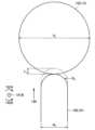
The suction device according to this embodiment heats the content contained in the base material to generate a substance to be sucked by the user. In particular, the suction device according to the present embodiment generates aerosol by heating a substrate including an aerosol source from inside the substrate. An aerosol is one example of a substance that is inhaled by a user. An aerosol source is one example of a content contained in a substrate. Alternatively, the substance produced by the suction device may be a gas. In the following, the user's suctioning of the substance produced by the suction device is also simply referred to as "sucking" or "puffing". Each configuration example of the suction device will be described below. Hereinafter, a configuration example of the suction device according to the present embodiment will be described with reference to FIG.

図1は、吸引装置の構成例を模式的に示す模式図である。図1に示すように、本構成例に係る吸引装置100は、電源部111、センサ部112、通知部113、記憶部114、通信部115、制御部116、加熱部121、圧縮部160及び保持部140を含む。保持部140にスティック型基材150が保持された状態で、ユーザによる吸引が行われる。以下、各構成要素について順に説明する。 FIG. 1 is a schematic diagram schematically showing a configuration example of a suction device. As shown in FIG. 1, thesuction device 100 according to this configuration example includes apower supply unit 111, asensor unit 112, anotification unit 113, astorage unit 114, acommunication unit 115, acontrol unit 116, aheating unit 121, acompression unit 160, and a holding unit. Includingpart 140 . The user performs suction while the stick-shapedsubstrate 150 is held by the holdingportion 140 . Each component will be described in order below.

電源部111は、電力を蓄積する。そして、電源部111は、吸引装置100の各構成要素に、電力を供給する。電源部111は、例えば、リチウムイオン二次電池等の充電式バッテリにより構成され得る。電源部111は、USB(Universal Serial Bus)ケーブル等により外部電源に接続されることで、充電されてもよい。また、電源部111は、ワイヤレス電力伝送技術により送電側のデバイスに非接続な状態で充電されてもよい。他にも、電源部111のみを吸引装置100から取り外すことができてもよく、新しい電源部111と交換することができてもよい。 Thepower supply unit 111 accumulates power. Thepower supply unit 111 supplies electric power to each component of thesuction device 100 . Thepower supply unit 111 may be composed of, for example, a rechargeable battery such as a lithium ion secondary battery. Thepower supply unit 111 may be charged by being connected to an external power supply via a USB (Universal Serial Bus) cable or the like. Also, thepower supply unit 111 may be charged in a state of being disconnected from the device on the power transmission side by wireless power transmission technology. Alternatively, only thepower supply unit 111 may be detached from thesuction device 100 or may be replaced with a newpower supply unit 111 .

センサ部112は、吸引装置100に関する各種情報を検出する。そして、センサ部112は、検出した情報を制御部116に出力する。一例として、センサ部112は、マイクロホンコンデンサ等の圧力センサにより構成される。そして、センサ部112は、ユーザによる吸引に伴う負圧を検出した場合に、ユーザによる吸引が行われたことを示す情報を制御部116に出力する。他の一例として、センサ部112は、ボタン又はスイッチ等の、ユーザからの情報の入力を受け付ける入力装置により構成される。とりわけ、センサ部112は、エアロゾルの生成開始/停止を指示するボタンを含み得る。そして、センサ部112は、ユーザにより入力された情報を制御部116に出力する。他の一例として、センサ部112は、加熱部121の温度を検出する温度センサにより構成される。かかる温度センサは、例えば、加熱部121の導電トラックの電気抵抗値に基づいて加熱部121の温度を検出する。センサ部112は、加熱部121の温度に基づいて、保持部140により保持されたスティック型基材150の温度を検出してもよい。 Thesensor unit 112 detects various information regarding thesuction device 100 . Thesensor unit 112 then outputs the detected information to thecontrol unit 116 . As an example, thesensor unit 112 is configured by a pressure sensor such as a microphone condenser. When thesensor unit 112 detects the negative pressure associated with the user's suction, thesensor unit 112 outputs information indicating that the user has performed suction to thecontrol unit 116 . As another example, thesensor unit 112 is configured by an input device, such as a button or switch, that receives information input from the user. Among other things,sensor unit 112 may include a button for instructing start/stop of aerosol generation. Thesensor unit 112 then outputs the information input by the user to thecontrol unit 116 . As another example, thesensor section 112 is configured by a temperature sensor that detects the temperature of theheating section 121 . Such a temperature sensor detects the temperature of theheating portion 121 based on the electrical resistance value of the conductive tracks of theheating portion 121, for example. Thesensor section 112 may detect the temperature of the stick-shapedsubstrate 150 held by the holdingsection 140 based on the temperature of theheating section 121 .

通知部113は、情報をユーザに通知する。一例として、通知部113は、LED(Light Emitting Diode)などの発光装置により構成される。その場合、通知部113は、電源部111の状態が要充電である場合、電源部111が充電中である場合、及び吸引装置100に異常が発生した場合等に、それぞれ異なる発光パターンで発光する。ここでの発光パターンとは、色、及び点灯/消灯のタイミング等を含む概念である。通知部113は、発光装置と共に、又は代えて、画像を表示する表示装置、音を出力する音出力装置、及び振動する振動装置等により構成されてもよい。他にも、通知部113は、ユーザによる吸引が可能になったことを示す情報を通知してもよい。ユーザによる吸引が可能になったことを示す情報は、加熱部121により加熱されたスティック型基材150の温度が所定の温度に達した場合に、通知される。 Thenotification unit 113 notifies the user of information. As an example, thenotification unit 113 is configured by a light emitting device such as an LED (Light Emitting Diode). In this case, thenotification unit 113 emits light in different light emission patterns when thepower supply unit 111 is in a charging required state, when thepower supply unit 111 is being charged, when an abnormality occurs in thesuction device 100, and the like. . The light emission pattern here is a concept including color, timing of lighting/lighting out, and the like. Thenotification unit 113 may be configured by a display device that displays an image, a sound output device that outputs sound, a vibration device that vibrates, or the like, together with or instead of the light emitting device. In addition, thenotification unit 113 may notify information indicating that suction by the user has become possible. Information indicating that suction by the user is enabled is notified when the temperature of the stick-shapedbase material 150 heated by theheating unit 121 reaches a predetermined temperature.

記憶部114は、吸引装置100の動作のための各種情報を記憶する。記憶部114は、例えば、フラッシュメモリ等の不揮発性の記憶媒体により構成される。記憶部114に記憶される情報の一例は、制御部116による各種構成要素の制御内容等の、吸引装置100のOS(Operating System)に関する情報である。記憶部114に記憶される情報の他の一例は、吸引回数、吸引時刻、吸引時間累計等の、ユーザによる吸引に関する情報である。 Thestorage unit 114 stores various information for operation of thesuction device 100 . Thestorage unit 114 is configured by, for example, a non-volatile storage medium such as flash memory. An example of the information stored in thestorage unit 114 is information regarding the OS (Operating System) of thesuction device 100, such as control details of various components by thecontrol unit 116. FIG. Another example of the information stored in thestorage unit 114 is information related to suction by the user, such as the number of times of suction, suction time, total suction time, and the like.

通信部115は、吸引装置100と他の装置との間で情報を送受信するための、通信インタフェースである。通信部115は、有線又は無線の任意の通信規格に準拠した通信を行う。かかる通信規格としては、例えば、無線LAN(Local Area Network)、有線LAN、Wi-Fi(登録商標)、又はBluetooth(登録商標)等が採用され得る。一例として、通信部115は、ユーザによる吸引に関する情報をスマートフォンに表示させるために、ユーザによる吸引に関する情報をスマートフォンに送信する。他の一例として、通信部115は、記憶部114に記憶されているOSの情報を更新するために、サーバから新たなOSの情報を受信する。 Thecommunication unit 115 is a communication interface for transmitting and receiving information between thesuction device 100 and other devices. Thecommunication unit 115 performs communication conforming to any wired or wireless communication standard. As such a communication standard, for example, a wireless LAN (Local Area Network), a wired LAN, Wi-Fi (registered trademark), Bluetooth (registered trademark), or the like can be adopted. As an example, thecommunication unit 115 transmits information regarding suction by the user to the smartphone in order to display the information regarding suction by the user on the smartphone. As another example, thecommunication unit 115 receives new OS information from the server in order to update the OS information stored in thestorage unit 114 .

制御部116は、演算処理装置及び制御装置として機能し、各種プログラムに従って吸引装置100内の動作全般を制御する。制御部116は、例えばCPU(Central Processing Unit)、及びマイクロプロセッサ等の電子回路によって実現される。他に、制御部116は、使用するプログラム及び演算パラメータ等を記憶するROM(Read Only Memory)、並びに適宜変化するパラメータ等を一時記憶するRAM(Random Access Memory)を含んでいてもよい。吸引装置100は、制御部116による制御に基づいて、各種処理を実行する。電源部111から他の各構成要素への給電、電源部111の充電、センサ部112による情報の検出、通知部113による情報の通知、記憶部114による情報の記憶及び読み出し、並びに通信部115による情報の送受信は、制御部116により制御される処理の一例である。圧縮部160による圧縮及び開放(圧縮停止)もまた、制御部116により制御される処理の一例である。各構成要素への情報の入力、及び各構成要素から出力された情報に基づく処理等、吸引装置100により実行されるその他の処理も、制御部116により制御される。 Thecontrol unit 116 functions as an arithmetic processing device and a control device, and controls overall operations within thesuction device 100 according to various programs. Thecontrol unit 116 is realized by electronic circuits such as a CPU (Central Processing Unit) and a microprocessor, for example. In addition, thecontrol unit 116 may include a ROM (Read Only Memory) that stores programs to be used, calculation parameters, and the like, and a RAM (Random Access Memory) that temporarily stores parameters that change as appropriate. Thesuction device 100 executes various processes under the control of thecontroller 116 . Power supply frompower supply unit 111 to other components, charging ofpower supply unit 111, detection of information bysensor unit 112, notification of information bynotification unit 113, storage and reading of information bystorage unit 114, andcommunication unit 115 Transmission and reception of information is an example of processing controlled by thecontrol unit 116 . Compression and release (compression stop) by thecompression unit 160 are also examples of processing controlled by thecontrol unit 116 . Other processes executed by thesuction device 100, such as information input to each component and processing based on information output from each component, are also controlled by thecontrol unit 116. FIG.

保持部140は、内部空間141を形成し、内部空間141にスティック型基材150の一部を収容しながらスティック型基材150を保持する。保持部140は、内部空間141を外部に連通する開口142を有し、開口142から内部空間141に挿入されたスティック型基材150を保持する。例えば、保持部140は、開口142及び底部143を底面とする筒状体であり、柱状の内部空間141を画定する。保持部140は、スティック型基材150へ供給される空気の流路を画定する機能も有する。かかる流路内への空気の入り口である空気流入孔は、例えば底部143に配置される。他方、かかる流路からの空気の出口である空気流出孔は、開口142である。 The holdingpart 140 forms aninternal space 141 and holds the stick-shapedbase material 150 while accommodating a part of the stick-shapedbase material 150 in theinternal space 141 . The holdingpart 140 has anopening 142 that communicates theinternal space 141 with the outside, and holds the stick-shapedsubstrate 150 inserted into theinternal space 141 through theopening 142 . For example, the holdingportion 140 is a cylindrical body having anopening 142 and abottom portion 143 as a bottom surface, and defines a columnarinternal space 141 . The holdingpart 140 also has a function of defining a flow path for air supplied to the stick-shapedsubstrate 150 . An air inlet hole, which is an inlet for air into the flow path, is arranged, for example, in thebottom portion 143 . On the other hand, the air outflow hole, which is the exit of air from such a channel, is theopening 142 .

スティック型基材150は、スティック型の部材である。スティック型基材150の外周は、シート状の部材により巻かれることで形成される。シート状の部材の一例は、巻紙である。スティック型基材150は、基材部151、及び吸口部152を含む。 The stick-shapedbase material 150 is a stick-shaped member. The outer circumference of the stick-shapedbase material 150 is formed by winding a sheet-like member. An example of a sheet-like member is a wrapping paper. The stick-type substrate 150 includes asubstrate portion 151 and amouthpiece portion 152 .

基材部151は、エアロゾル源を含む。エアロゾル源は、加熱されることで霧化され、エアロゾルが生成される。エアロゾル源は、例えば、グリセリン及びプロピレングリコール等の多価アルコール、並びに水等の液体である。エアロゾル源は、加熱されることによって香味成分を放出する、たばこ原料又はたばこ原料由来の抽出物をさらに含んでいてもよい。吸引装置100が医療用吸入器である場合、エアロゾル源は、患者が吸入するための薬剤を含んでもよい。なお、エアロゾル源は液体に限られるものではなく、固体であってもよい。基材部151の少なくとも一部は、スティック型基材150が保持部140に保持された状態において、保持部140の内部空間141に収容される。Substrate portion 151 includes an aerosol source. The aerosol source is atomized by heating to produce an aerosol. Aerosol sources are, for example, polyhydric alcohols such as glycerin and propylene glycol, and liquids such as water. The aerosol source may further comprise a tobacco material or an extract derived therefrom that releases flavoring components when heated. If theinhalation device 100 is a medical inhaler, the aerosol source may contain a medicament for inhalation by the patient. Note that the aerosol source is not limited to a liquid, and may be a solid. At least a portion of thebase material portion 151 is accommodated in theinternal space 141 of the holdingportion 140 while the stick-shapedbase material 150 is held by the holdingportion 140 .

とりわけ、エアロゾル源は、粒子状又はシート状等の任意の形状の物体に含有され、基材部151に充填される。エアロゾル源が含有される物体を、以下では基材要素とも称する。基材要素は、空気の流路を塞がないよう、隙間がある状態で基材部151に充填される。 Above all, the aerosol source is contained in an object having an arbitrary shape such as particles or sheets, and thesubstrate portion 151 is filled with the object. An object containing an aerosol source is hereinafter also referred to as a substrate element. The base material element is filled in thebase material part 151 with a gap so as not to block the air flow path.

吸口部152は、吸引の際にユーザに咥えられる部材である。吸口部152の少なくとも一部は、スティック型基材150が保持部140に保持された状態において、開口142から突出する。そして、開口142から突出した吸口部152をユーザが咥えて吸引すると、図示しない空気流入孔から保持部140の内部に空気が流入する。流入した空気は、保持部140の内部空間141を通過して、基材部151から発生するエアロゾルと共に、ユーザの口内に到達する。 Themouthpiece 152 is a member held by the user when inhaling. At least part of themouthpiece 152 protrudes from theopening 142 when the stick-shapedbase material 150 is held by the holdingpart 140 . Then, when the user holds themouthpiece 152 protruding from theopening 142 and sucks, air flows into the inside of the holdingpart 140 from an air inlet hole (not shown). The inflowing air passes through theinternal space 141 of the holdingportion 140 and reaches the user's mouth together with the aerosol generated from thebase portion 151 .

加熱部121は、エアロゾル源を加熱することで、エアロゾル源を霧化してエアロゾルを生成する。加熱部121は、金属又はポリイミド等の任意の素材で構成される。例えば、加熱部121は、ブレード状又は柱状(例えば、針状)等の任意の形状に構成され、保持部140の底部143から保持部140の内部空間141に突出するようにして配置される。そのため、保持部140にスティック型基材150が挿入されると、加熱部121は、スティック型基材150の基材部151に突き刺さるようにして、スティック型基材150の内部に挿入される。そして、加熱部121が発熱すると、スティック型基材150に含まれるエアロゾル源がスティック型基材150の内部から加熱されて霧化され、エアロゾルが生成される。加熱部121は、電源部111から給電されると発熱する。一例として、所定のユーザ入力が行われたことがセンサ部112により検出された場合に、給電され、エアロゾルが生成されてもよい。加熱部121により加熱されたスティック型基材150の温度が所定の温度に達した場合に、ユーザによる吸引が可能となる。その後、所定のユーザ入力が行われたことがセンサ部112により検出された場合、又は所定時間経過した場合に、給電が停止されてもよい。他の一例として、ユーザによる吸引が行われたことがセンサ部112により検出されている期間において、給電され、エアロゾルが生成されてもよい。 Theheating unit 121 heats the aerosol source to atomize the aerosol source and generate an aerosol. Theheating part 121 is made of any material such as metal or polyimide. For example, theheating part 121 is formed in an arbitrary shape such as a blade shape or a columnar shape (for example, a needle shape), and is arranged so as to protrude from thebottom part 143 of the holdingpart 140 into theinternal space 141 of the holdingpart 140 . Therefore, when the stick-shapedsubstrate 150 is inserted into the holdingportion 140 , theheating portion 121 is inserted into the stick-shapedsubstrate 150 so as to pierce thesubstrate portion 151 of the stick-shapedsubstrate 150 . Then, when theheating part 121 generates heat, the aerosol source contained in the stick-shapedsubstrate 150 is heated from the inside of the stick-shapedsubstrate 150 and atomized to generate an aerosol. Theheating unit 121 generates heat when supplied with power from thepower supply unit 111 . As an example, power may be supplied and an aerosol may be generated when thesensor unit 112 detects that a predetermined user input has been performed. When the temperature of the stick-shapedbase material 150 heated by theheating unit 121 reaches a predetermined temperature, suction by the user becomes possible. After that, when thesensor unit 112 detects that a predetermined user input has been performed, or when a predetermined period of time has elapsed, power supply may be stopped. As another example, power may be supplied and aerosol may be generated during a period in which thesensor unit 112 detects that the user has inhaled.

スティック型基材150の温度の温度が所定の温度に達するまで実行される加熱は、予備加熱とも称される。また、かかる所定の温度を、吸引可能温度とも称する。吸引可能温度に到達するまでにかかる時間を、以下では予備加熱時間とも称する。予備加熱によりスティック型基材150の温度が吸引可能温度に達した後も、温度を維持するための加熱が行われ得る。 The heating performed until the temperature of the stick-type substrate 150 reaches a predetermined temperature is also called preheating. Moreover, such a predetermined temperature is also referred to as a suckable temperature. The time required to reach the suckable temperature is hereinafter also referred to as preheating time. Even after the temperature of the stick-type base material 150 reaches the suckable temperature due to preheating, heating may be performed to maintain the temperature.

圧縮部160は、保持部140により保持されたスティック型基材150を圧縮する。とりわけ、圧縮部160は、保持部140により保持されたスティック型基材150のうち、加熱部121により加熱される部分である被加熱部分を外周から加熱部121の方向190へ圧縮する。基材部151は、被加熱部分の一例である。かかる方向を、以下では圧縮方向190とも称する。圧縮部160がスティック型基材150を圧縮している状態を、圧縮状態とも称する。圧縮部160がスティック型基材150を圧縮していない状態を、開放状態とも称する。圧縮部160に関する詳細な構成については、次に詳しく説明する。 Thecompressing section 160 compresses the stick-shapedsubstrate 150 held by the holdingsection 140 . In particular, the compressingportion 160 compresses the portion to be heated by theheating portion 121 of the stick-shapedbase material 150 held by the holdingportion 140 in thedirection 190 of theheating portion 121 from the outer circumference. Thebase material portion 151 is an example of a heated portion. Such a direction is also referred to below ascompression direction 190 . The state in which the compressingportion 160 compresses the stick-shapedbase material 150 is also referred to as a compressed state. A state in which the compressingportion 160 does not compress the stick-shapedsubstrate 150 is also referred to as an open state. A detailed configuration of thecompression unit 160 will be described in detail below.

<<2.圧縮機構の構成>>
(1)全体構成
以下、図2~図5を参照しながら、圧縮部160がスティック型基材150を圧縮する機構の一例を説明する。
<<2. Configuration of Compression Mechanism>>
(1) Overall Configuration An example of a mechanism in which thecompression section 160 compresses the stick-shapedbase material 150 will be described below with reference to FIGS. 2 to 5. FIG.

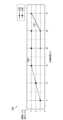
図2は、本実施形態に係る吸引装置100の分解斜視図である。図3は、本実施形態に係る吸引装置100の挿抜方向191に平行する断面の一例を示す断面図である。図4は、本実施形態に係る吸引装置100の開放状態における挿抜方向191に直交する断面の一例を示す断面図である。図5は、本実施形態に係る吸引装置100の圧縮状態における挿抜方向191に直交する断面の一例を示す断面図である。 FIG. 2 is an exploded perspective view of thesuction device 100 according to this embodiment. FIG. 3 is a cross-sectional view showing an example of a cross section parallel to the insertion/removal direction 191 of thesuction device 100 according to this embodiment. FIG. 4 is a cross-sectional view showing an example of a cross section perpendicular to the insertion/removal direction 191 in the open state of thesuction device 100 according to this embodiment. FIG. 5 is a cross-sectional view showing an example of a cross section perpendicular to the insertion/removal direction 191 in the compressed state of thesuction device 100 according to this embodiment.

図2~図5に示すように吸引装置100は、圧縮部160(160A~160C)、加熱部121、縁部171、内壁部172、第1回転部174、第2回転部175、第1底部177、第2底部178を含む。なお、これらの図では、保持部140、加熱部121、及び圧縮部160に関する構成要素が図示されており、その他の構成要素は省略されている。 As shown in FIGS. 2 to 5, thesuction device 100 includes a compressing portion 160 (160A to 160C), aheating portion 121, anedge portion 171, aninner wall portion 172, a firstrotating portion 174, a secondrotating portion 175, and a first bottom portion. 177 , including asecond bottom 178 . In addition, in these figures, constituent elements related to theholding section 140, theheating section 121, and thecompressing section 160 are illustrated, and other constituent elements are omitted.

圧縮方向190は、吸引装置100が有する複数の圧縮部160(160A~160C)の各々に対し設定される。例えば、圧縮方向190Aは、圧縮部160Aから加熱部121への方向である。圧縮方向190Bは、圧縮部160Bから加熱部121への方向である。圧縮方向190Cは、圧縮部160Cから加熱部121への方向である。 Thecompression direction 190 is set for each of the plurality of compression portions 160 (160A to 160C) of thesuction device 100. As shown in FIG. For example, thecompression direction 190A is the direction from thecompression section 160A to theheating section 121 . Thecompression direction 190B is the direction from thecompression section 160B to theheating section 121 . Thecompression direction 190C is the direction from thecompression section 160C to theheating section 121 .

挿抜方向191とは、吸引装置100にスティック型基材150を挿入する又は引き抜く方向である。挿抜方向191のうち、スティック型基材150を挿入する方向を挿入方向191Aとも称する。挿抜方向191のうち、スティック型基材150を引き抜く方向を引抜方向191Bとも称する。挿抜方向191は、複数の圧縮方向190A~190Cと直交する。スティック型基材150は、スティック型基材150の長手方向が挿抜方向191に一致するようにして、吸引装置100に挿入される。 The insertion/removal direction 191 is the direction in which the stick-shapedsubstrate 150 is inserted into or pulled out from thesuction device 100 . Of the insertion/extraction direction 191, the direction in which the stick-shapedsubstrate 150 is inserted is also referred to as aninsertion direction 191A. Of the insertion/extraction direction 191, the direction in which the stick-shapedsubstrate 150 is pulled out is also referred to as theextraction direction 191B. The insertion/removal direction 191 is orthogonal to the plurality ofcompression directions 190A-190C. The stick-shapedbase material 150 is inserted into thesuction device 100 such that the longitudinal direction of the stick-shapedbase material 150 matches the insertion/removal direction 191 .

挿抜方向191を回転軸として回転する方向を回転方向192とも称する。回転方向192のうち、挿入方向191Aを向いた状態で時計回りの方向を右回転方向192Aとも称する。回転方向192のうち、挿入方向191Aを向いた状態で反時計回りの方向を左回転方向192Bとも称する。 The direction of rotation with the insertion/removal direction 191 as the rotation axis is also referred to as the rotation direction 192 . Among the rotation directions 192, the clockwise direction in a state facing theinsertion direction 191A is also referred to as aright rotation direction 192A. Among the rotation directions 192, the counterclockwise direction in a state facing theinsertion direction 191A is also referred to as acounterclockwise rotation direction 192B.

以下、図2~図5に示した各構成要素を順に説明しながら、圧縮部160に関する特徴を詳細に説明する。ただし、説明の際には、圧縮部160Aに関する特徴を代表として説明する場合がある。もちろん、圧縮部160B及び圧縮部160Cは、圧縮部160Aに関する特徴と同様の特徴を有する。 Hereinafter, features of thecompression unit 160 will be described in detail while sequentially describing each component shown in FIGS. 2 to 5. FIG. However, in the description, the characteristics of thecompression unit 160A may be described as a representative. Of course,compression section 160B andcompression section 160C have features similar to those associated withcompression section 160A.

縁部171は、保持部140の開口142の縁を覆う部材である。縁部171は、円筒筒状に構成される。そして、縁部171は、内壁部172及び第2回転部175の引抜方向191B側の端部に配置される。 Theedge portion 171 is a member that covers the edge of theopening 142 of the holdingportion 140 . Theedge portion 171 is configured in a cylindrical tubular shape. Theedge portion 171 is arranged at the end portion of theinner wall portion 172 and the secondrotating portion 175 on thepullout direction 191B side.

内壁部172は、保持部140の内部空間141の内壁を構成する部材である。内壁部172は、円筒状に構成される。内壁部172には、第1開口部173(173A~173C)が設けられる。第1開口部173は、圧縮部160の爪部161が通過可能な大きさを有する。内壁部172は、第2回転部175のうち、引抜方向191B側の円筒状に構成された上部分175Bの内側に収容されるように、配置される。とりわけ、内壁部172は、第1開口部173の位置と第2回転部175の上部分175Bに設けられる第2開口部176の位置とが一致するように、配置される。内壁部172内側の空間は、保持部140の内部空間141に相当する。 Theinner wall portion 172 is a member forming the inner wall of theinternal space 141 of the holdingportion 140 . Theinner wall portion 172 is configured in a cylindrical shape. Theinner wall portion 172 is provided with a first opening portion 173 (173A to 173C). The first opening 173 has a size through which the claw portion 161 of the compressingportion 160 can pass. Theinner wall portion 172 is arranged so as to be accommodated inside a cylindricalupper portion 175B of the secondrotating portion 175 on thepullout direction 191B side. In particular, theinner wall portion 172 is arranged such that the position of the first opening 173 and the position of the second opening 176 provided in theupper portion 175B of the secondrotating portion 175 are aligned. The space inside theinner wall portion 172 corresponds to theinner space 141 of the holdingportion 140 .

第1回転部174は、回転方向192に回転可能な部材である。第1回転部174は、円筒状に構成される。第1回転部174は、第2回転部175の上部分175Bの外周を覆うように配置される。第1回転部174の内壁面179は、圧縮方向190における高さが、回転方向192に沿って変化するように形成される。 The firstrotating portion 174 is a member rotatable in the rotating direction 192 . The firstrotating portion 174 is configured in a cylindrical shape. The firstrotating portion 174 is arranged so as to cover the outer periphery of theupper portion 175B of the secondrotating portion 175 . The inner wall surface 179 of the firstrotating portion 174 is formed such that the height in thecompression direction 190 varies along the rotation direction 192 .

第2回転部175は、回転方向192に回転可能な部材である。第2回転部175は、引抜方向191B側の部分である上部分175Bと、挿入方向191A側の部分である下部分175Aと、を含む。上部分175B及び下部分175Aは、それぞれ円筒状に構成される。上部分175Bの断面外径は、下部分175Aの断面外径よりも小さい。とりわけ、上部分175Bの断面外径は、第1回転部174の断面内径よりも小さい。そして、第2回転部175は、上部分175Bが第1回転部174の内部に収容されるように、配置される。他方、下部分175Aの断面外径は、典型的には、第1回転部174の断面外径と同一又は略同一に構成される。これにより、下部分175Aの外周と第1回転部174の外周と境界における段差が最小化される。上部分175Bには、第2開口部176(176A~176C)が設けられる。第2開口部176は、圧縮部160の爪部161が通過可能な大きさを有する。 The secondrotating portion 175 is a member rotatable in the rotating direction 192 . The secondrotating portion 175 includes anupper portion 175B, which is a portion on thewithdrawal direction 191B side, and alower portion 175A, which is a portion on theinsertion direction 191A side. Theupper portion 175B and thelower portion 175A are each configured in a cylindrical shape. The cross-sectional outer diameter of theupper portion 175B is smaller than the cross-sectional outer diameter of thelower portion 175A. In particular, the cross-sectional outer diameter of theupper portion 175B is smaller than the cross-sectional inner diameter of the firstrotating portion 174 . The secondrotating portion 175 is arranged such that theupper portion 175B is housed inside the firstrotating portion 174 . On the other hand, the cross-sectional outer diameter of thelower portion 175A is typically configured to be the same or substantially the same as the cross-sectional outer diameter of the firstrotating portion 174 . As a result, the step between the outer periphery of thelower portion 175A and the outer periphery of the firstrotating portion 174 and the boundary is minimized. A second opening 176 (176A to 176C) is provided in theupper portion 175B. The second opening 176 has a size through which the claw portion 161 of the compressingportion 160 can pass.

第1回転部174及び第2回転部175は、互いに逆方向に回転する。そして、第1回転部174及び第2回転部175が回転することで、圧縮部160は、スティック型基材150を圧縮したり開放したりする。以下では、第2回転部175を固定して、第1回転部174を右回転方向192A又は左回転方向192Bに回転させるものとして説明する。なお、第1回転部174及び第2回転部175の回転は、ユーザにより手動で行われてもよい。また、第1回転部174及び第2回転部175の回転は、図示しないモータ等の機構により、自動で行われてもよい。 The firstrotating portion 174 and the secondrotating portion 175 rotate in opposite directions. As the firstrotating portion 174 and the secondrotating portion 175 rotate, the compressingportion 160 compresses and releases the stick-shapedsubstrate 150 . In the following description, it is assumed that the secondrotating portion 175 is fixed and the firstrotating portion 174 is rotated in theclockwise rotation direction 192A or thecounterclockwise rotation direction 192B. The rotation of the firstrotating portion 174 and the secondrotating portion 175 may be manually performed by the user. Further, the rotation of the firstrotating portion 174 and the secondrotating portion 175 may be automatically performed by a mechanism such as a motor (not shown).

第1底部177及び第2底部178は、吸引装置100の挿入方向191Aの端部を構成する部材である。第1底部177と第2底部178とは、第1底部177から加熱部121の先端が突き出た状態で、且つ第1底部177と第2底部178との間に加熱部121を挟んだ状態で、嵌合される。そして、第1底部177及び第2底部178は、第2回転部175の上部分175Bの内部に配置された内壁部172の内部空間に、第1底部177から突き出た加熱部121の先端を挿入するようにして、第2回転部175の下部分175Aに嵌合される。 Thefirst bottom portion 177 and thesecond bottom portion 178 are members that constitute the ends of thesuction device 100 in theinsertion direction 191A. Thefirst bottom portion 177 and thesecond bottom portion 178 are arranged such that the tip of theheating portion 121 protrudes from thefirst bottom portion 177 and theheating portion 121 is sandwiched between thefirst bottom portion 177 and thesecond bottom portion 178. , are mated. Then, thefirst bottom portion 177 and thesecond bottom portion 178 insert the tip of theheating portion 121 protruding from thefirst bottom portion 177 into the internal space of theinner wall portion 172 arranged inside theupper portion 175B of the secondrotating portion 175. It is fitted to thelower portion 175A of the secondrotating portion 175 in such a manner.

加熱部121は、内壁部172の内部空間に先端が突出するように配置される。スティック型基材150が内壁部172の内部空間に挿入されると、加熱部121の先端は、スティック型基材150の基材部151に突き刺さるようにして、スティック型基材150の内部に挿入される。加熱部121は、発熱することで、周囲の基材要素に含まれるエアロゾル源を加熱することができる。 Theheating part 121 is arranged so that its tip protrudes into the internal space of theinner wall part 172 . When the stick-shapedsubstrate 150 is inserted into the internal space of theinner wall portion 172, the tip of theheating portion 121 is inserted into the stick-shapedsubstrate 150 so as to pierce thesubstrate portion 151 of the stick-shapedsubstrate 150. be done. Theheating part 121 can heat the aerosol source contained in the surrounding base material element by generating heat.

本構成に係る吸引装置100は、圧縮部160として、圧縮部160A~160Cの3つの圧縮部160を有する。そして、3つの圧縮部160は、それぞれ異なる3方向からスティック型基材150を圧縮する。かかる構成により、保持部140の内部空間141内でのスティック型基材150の位置及び姿勢に依存せず、複数の圧縮部160の全てがスティック型基材150を圧縮することが可能となる。 Thesuction device 100 according to this configuration has threecompression sections 160, ie,compression sections 160A to 160C. The threecompression units 160 compress the stick-shapedbase material 150 from three different directions. With such a configuration, all of the plurality ofcompression parts 160 can compress the stick-shapedbase material 150 regardless of the position and posture of the stick-shapedbase material 150 within theinternal space 141 of the holdingpart 140 .

圧縮部160は、爪部161と基部162とを含んで構成される。爪部161は、挿抜方向191及び圧縮方向190に延びる板状の部材として構成される。基部162は、挿抜方向191に延びる棒状の部材として構成される。圧縮部160は、基部162が第1回転部174の内壁面179に接触し、且つ爪部161の位置と第1開口部173及び第2開口部176の位置とが一致するように、配置される。なお、圧縮部160と第2回転部175との間に、圧縮部160に対し圧縮方向190とは逆方向に反発力を生じさせる、ばね等の機構が設けられる。 The compressingportion 160 includes a claw portion 161 and a base portion 162 . The claw portion 161 is configured as a plate-like member extending in the insertion/removal direction 191 and thecompression direction 190 . The base 162 is configured as a rod-shaped member extending in the insertion/removal direction 191 . Thecompression portion 160 is arranged such that the base portion 162 is in contact with the inner wall surface 179 of the firstrotating portion 174 and the positions of the claw portion 161 and the positions of the first opening portion 173 and the second opening portion 176 are aligned. be. A mechanism such as a spring is provided between the compressingportion 160 and the secondrotating portion 175 to generate a repulsive force against the compressingportion 160 in a direction opposite to the compressingdirection 190 .

圧縮部160は、圧縮方向190に移動することで、スティック型基材150を圧縮する。詳しくは、第1回転部174が回転すると、基部162が第1回転部174の内壁面179を滑動する。その結果、圧縮方向190における内壁面179の高さの変化に従って、圧縮方向190における圧縮部160の位置が変化する。 Thecompression part 160 compresses the stick-shapedsubstrate 150 by moving in thecompression direction 190 . Specifically, when the firstrotating portion 174 rotates, the base portion 162 slides on the inner wall surface 179 of the firstrotating portion 174 . As a result, the position of thecompressed portion 160 in thecompression direction 190 changes as the height of the inner wall surface 179 changes in thecompression direction 190 .

ここで、第1回転部174の内壁面179は、複数の圧縮部160の各々に関し、圧縮方向190における高さが、右回転方向192Aほど高く、左回転方向192Bほど低くなるように構成される。例えば、圧縮部160Aの基部162Aが接触する内壁面179Aは、圧縮方向190における高さが、右回転方向192Aほど高く、左回転方向192Bほど低くなるように構成される。 Here, the inner wall surface 179 of the firstrotating portion 174 is configured such that the height in the compressingdirection 190 of each of the plurality of compressingportions 160 is higher in the clockwiserotating direction 192A and lower in the counterclockwiserotating direction 192B. . For example, theinner wall surface 179A with which thebase portion 162A of thecompression portion 160A contacts is configured such that the height in thecompression direction 190 is higher in theclockwise rotation direction 192A and lower in thecounterclockwise rotation direction 192B.

そのため、第1回転部174が左回転方向192Bに回転すると、基部162が接触する位置における内壁面179の高さが徐々に高くなるので、圧縮部160は圧縮方向190に移動する。例えば、第1回転部174が左回転方向192Bに回転すると、圧縮部160Aの基部162Aが接触する位置における内壁面179Aの高さが徐々に高くなるので、圧縮部160Aは圧縮方向190Aに移動する。その結果、図5に示すように、爪部161は、第1開口部173及び第2開口部176を通ってスティック型基材150を押圧することとなる。例えば、圧縮部160Aの爪部161Aは、第1開口部173A及び第2開口部176Aを通ってスティック型基材150を押圧することとなる。 Therefore, when the firstrotating portion 174 rotates in thecounterclockwise rotation direction 192B, the height of the inner wall surface 179 at the position where the base portion 162 contacts gradually increases, so the compressingportion 160 moves in the compressingdirection 190 . For example, when the firstrotating portion 174 rotates in thecounterclockwise rotation direction 192B, the height of theinner wall surface 179A at the position where thebase portion 162A of thecompression portion 160A contacts gradually increases, so thecompression portion 160A moves in thecompression direction 190A. . As a result, as shown in FIG. 5, the claw portion 161 presses the stick-shapedsubstrate 150 through the first opening portion 173 and the second opening portion 176 . For example, theclaw portion 161A of the compressingportion 160A presses the stick-shapedsubstrate 150 through thefirst opening portion 173A and thesecond opening portion 176A.

他方、第1回転部174が右回転方向192Aに回転すると、基部162が接触する位置における内壁面179の高さが徐々に低くなる。そのため、圧縮部160と第2回転部175との間に設けられたばね等の機構により生じた反発力を受けて、圧縮部160は圧縮方向190と反対方向に移動する。例えば、第1回転部174が右回転方向192Aに回転すると、圧縮部160Aの基部162Aが接触する位置における内壁面179Aの高さが徐々に低くなるので、圧縮部160Aは圧縮方向190Aと反対方向に移動する。その結果、図4に示すように、爪部161が第1開口部173及び第2開口部176を通ってスティック型基材150から離れる。例えば、圧縮部160Aの爪部161Aは、第1開口部173A及び第2開口部176Aを通ってスティック型基材150から離れる。 On the other hand, when the firstrotating portion 174 rotates in theclockwise rotation direction 192A, the height of the inner wall surface 179 at the position where the base portion 162 contacts gradually decreases. Therefore, the compressingportion 160 moves in the direction opposite to the compressingdirection 190 by receiving a repulsive force generated by a mechanism such as a spring provided between the compressingportion 160 and the secondrotating portion 175 . For example, when the firstrotating portion 174 rotates in theright rotation direction 192A, the height of theinner wall surface 179A at the position where thebase portion 162A of thecompression portion 160A contacts gradually decreases, so thecompression portion 160A rotates in the direction opposite to thecompression direction 190A. move to As a result, as shown in FIG. 4, the claw portion 161 passes through the first opening portion 173 and the second opening portion 176 and leaves the stick-shapedsubstrate 150 . For example, theclaw portion 161A of thecompression portion 160A leaves the stick-shapedsubstrate 150 through thefirst opening portion 173A and thesecond opening portion 176A.

(2)圧縮部160の先端形状
図6は、本実施形態に係る圧縮部160の挿抜方向191に直交する断面の一例を示す断面図である。図6に示すように、圧縮部160(より正確には、爪部161)のうち圧縮方向190の先端面の断面形状は、凸型であってもよい。とりわけ、圧縮部160(より正確には、爪部161)のうち圧縮方向190の先端面の断面形状は、凸型の円弧形状であってもよい。爪部161の先端面の円弧の幅W、爪部161の先端面の円弧の半径R、圧縮長L、及び基材部151の巻径Dとして、任意の寸法を採用可能である。なお、圧縮長Lとは、圧縮部160による圧縮の際に、圧縮部160(より正確には、爪部161)の先端面が基材部151の外周に接触してから移動する長さである。例えば、各種寸法は、下記の表1のように設定され得る。
(2) Tip Shape ofCompressing Portion 160 FIG. 6 is a cross-sectional view showing an example of a cross section orthogonal to the inserting/removing direction 191 of the compressingportion 160 according to the present embodiment. As shown in FIG. 6, the cross-sectional shape of the tip end face in thecompression direction 190 of the compression portion 160 (more precisely, the claw portion 161) may be convex. In particular, the cross-sectional shape of the distal end surface of the compressing portion 160 (more precisely, the claw portion 161) in the compressingdirection 190 may be a convex circular arc shape. Arbitrary dimensions can be adopted as the width WC of the arc of the tip end surface of the claw portion 161, the radius RC of the arc of the tip end surface of the claw portion 161, the compression length LC , and the winding diameter DS of thebase portion 151. be. The compression length LC is the length of movement after the tip surface of the compression portion 160 (more precisely, the claw portion 161) comes into contact with the outer circumference of thebase portion 151 during compression by thecompression portion 160. is. For example, various dimensions can be set as shown in Table 1 below.

Figure 0007290796000001

図7は、本実施形態に係る圧縮部160の挿抜方向191に直交する断面の一例を示す断面図である。図7に示すように、圧縮部160(より正確には、爪部161)のうち圧縮方向190の先端面の断面形状は、凹型であってもよい。とりわけ、圧縮部160(より正確には、爪部161)のうち圧縮方向190の先端面の断面形状は、凹型の円弧形状であってもよい。爪部161の先端面の円弧の幅W、爪部161の先端面の円弧の半径R、圧縮長L、及び基材部151の巻径Dとして、任意の寸法を採用可能である。爪部161の先端面の凹型の円弧の両端部分は、凸型の円弧状に形成されてもよい。そして、爪部161の先端面の円弧の両端部分の円弧の半径Rとして、任意の寸法を採用可能である。例えば、各種寸法は、下記の表2のように設定され得る。FIG. 7 is a cross-sectional view showing an example of a cross section perpendicular to the insertion/removal direction 191 of thecompression portion 160 according to this embodiment. As shown in FIG. 7, the cross-sectional shape of the tip end face in thecompression direction 190 of the compression portion 160 (more precisely, the claw portion 161) may be concave. In particular, the cross-sectional shape of the distal end surface of the compressing portion 160 (more precisely, the claw portion 161) in the compressingdirection 190 may be a concave circular arc shape. Arbitrary dimensions can be adopted as the width WC of the arc of the tip end surface of the claw portion 161, the radius RC of the arc of the tip end surface of the claw portion 161, the compression length LC , and the winding diameter DS of thebase portion 151. be. Both ends of the concave arc on the tip surface of the claw portion 161 may be formed in a convex arc shape. An arbitrary dimension can be adopted as the radiusRH of both ends of the arc of the tip surface of the claw portion 161 . For example, various dimensions can be set as shown in Table 2 below.

Figure 0007290796000002

(3)圧縮及び加熱のタイミング
本実施形態に係る吸引装置100は、加熱部121による加熱及び圧縮部160による圧縮の、一方の開始に基づいて他方を開始する。一例として、吸引装置100は、加熱部121による加熱の開始に基づいて、圧縮部160による圧縮を開始する。この場合、圧縮部160による圧縮は、自動で行われる。他の一例として、吸引装置100は、圧縮部160による圧縮の開始に基づいて、加熱部121による予備加熱を開始する。この場合、圧縮部160による圧縮は、手動で行われてもよいし、自動で行われてもよい。
(3) Compression and Heating Timing Thesuction device 100 according to the present embodiment starts heating by theheating unit 121 and compression by thecompression unit 160 based on the start of one of them. As an example, thesuction device 100 starts compression by thecompression section 160 based on the start of heating by theheating section 121 . In this case, compression by thecompression unit 160 is automatically performed. As another example, thesuction device 100 starts preheating by theheating unit 121 based on the start of compression by thecompression unit 160 . In this case, the compression by thecompression unit 160 may be performed manually or automatically.

加熱部121と基材要素との間に隙間がある場合、加熱部121から基材部151全体への熱伝導率が低下してしまい、効率的にエアロゾルを生成することが困難である。この点、圧縮と加熱とを同時に行うことにより、加熱部121と基材要素との接触面積を向上させることができるので、熱伝導率を向上させることができる。 If there is a gap between theheating part 121 and the base element, the thermal conductivity from theheating part 121 to the wholebase material part 151 is lowered, making it difficult to efficiently generate the aerosol. In this regard, by performing compression and heating simultaneously, the contact area between theheating portion 121 and the base element can be increased, so that the thermal conductivity can be improved.

基材部151内の基材要素間に隙間がある場合、加熱部121から基材部151全体への熱伝導率が低下してしまい、効率的にエアロゾルを生成することが困難である。この点、圧縮と加熱とを同時に行うことにより、基材部151内の基材要素の密度を向上させることができるので、熱伝導率を向上させることができる。 If there are gaps between the base elements in thebase member 151, the thermal conductivity from theheating unit 121 to theentire base member 151 is lowered, making it difficult to efficiently generate the aerosol. In this regard, by simultaneously performing compression and heating, the density of the base material elements in thebase material portion 151 can be improved, so that the thermal conductivity can be improved.

熱伝導率を向上させることにより、基材部151の昇温効果を向上させ、予備加熱時間を短縮することが可能となる。即ち、ユーザの吸引体験の質を向上させることが可能となる。 By improving the thermal conductivity, it is possible to improve the effect of raising the temperature of thebase member 151 and shorten the preheating time. That is, it is possible to improve the quality of the user's sucking experience.

また、吸引装置100は、圧縮部160による圧縮を開始してから所定時間経過した場合に、圧縮部160による圧縮を停止する。換言すると、吸引装置100は、圧縮時間を所定時間に制御する。圧縮時間とは、圧縮部160による圧縮を開始してから停止するまでの時間である。かかる構成により、後に実験結果を参照しながら詳しく説明するように、基材部151の昇温効果を向上させたり、吸引気体内のエアロゾルの成分量を向上させたり、固着及び抜けを軽減したりすることができる。即ち、ユーザの吸引体験の質を向上させることが可能となる。 In addition, thesuction device 100 stops the compression by thecompression section 160 when a predetermined time has passed since the compression by thecompression section 160 was started. In other words, thesuction device 100 controls the compression time to a predetermined time. The compression time is the time from when compression by thecompression unit 160 is started to when it is stopped. With such a configuration, as will be described later in detail with reference to experimental results, the effect of increasing the temperature of thebase member 151 can be improved, the amount of the aerosol component in the sucked gas can be improved, and sticking and removal can be reduced. can do. That is, it is possible to improve the quality of the user's sucking experience.

<<3.実験結果に基づく好適な構成>>
本発明者らは、圧縮部160による圧縮に関する各種実験を行い、吸引装置100の好適な構成を見出した。以下ではまず、各実験で共通する実験環境について説明する。その後、実験結果と吸引装置100好適な構成とを説明する。
<<3. Preferred configuration based on experimental results>>
The present inventors conducted various experiments regarding compression by thecompression unit 160 and found a suitable configuration of thesuction device 100 . First, the experimental environment common to each experiment will be described below. After that, experimental results and a preferred configuration of thesuction device 100 will be described.

圧縮部160の寸法は、上述した寸法C1~C4のいずれかである。圧縮部160による実効圧力は推定25Nであり、圧力は0.4Mpaである。圧縮部160の素材は、SSUS(Stainless Steel、ステンレス鋼)材、又はPEEK(Polyether Ether Ketone)材である。 The dimensions of thecompression portion 160 are any of the dimensions C1 to C4 described above. The effective pressure by thecompression part 160 is estimated to be 25N, and the pressure is 0.4Mpa. The material of thecompression part 160 is an SSUS (Stainless Steel) material or a PEEK (Polyether Ether Ketone) material.

加熱部121は、直径2.5mmの円柱状のセラミックヒーターである。加熱時の加熱部121の温度は350°Cである。加熱部121は、約25°Cの状態から350°Cに上昇する。スティック型基材150が吸引装置100に挿入されていない状態では、加熱部121の温度は一瞬で350°Cに上昇する。一方で、スティック型基材150が吸引装置100に挿入された状態では、加熱部121の温度が350°Cまで上昇するのに約10秒程度要する。なお、基材部151の温度は、基材部151に差し込まれた温度センサにより検出される。 Theheating unit 121 is a cylindrical ceramic heater with a diameter of 2.5 mm. The temperature of theheating part 121 during heating is 350°C. Theheating unit 121 rises from a state of approximately 25°C to 350°C. When the stick-type base material 150 is not inserted into thesuction device 100, the temperature of theheating section 121 instantly rises to 350°C. On the other hand, when the stick-type base material 150 is inserted into thesuction device 100, it takes about 10 seconds for the temperature of theheating section 121 to rise to 350°C. The temperature of thebase material portion 151 is detected by a temperature sensor inserted into thebase material portion 151 .

流量55cc/2秒のパフが機械により疑似的に行われる。パフは30秒間隔で行われる。エアロゾル源は、グリセリンである。吸引された気体(以下、吸引気体とも称する)内のエアロゾルの成分量は、ガスクロマトグラフィーにより分析される。 A puff with a flow rate of 55 cc/2 seconds is simulated by the machine. Puffs are made at 30 second intervals. The aerosol source is glycerin. The amount of aerosol components in the sucked gas (hereinafter also referred to as sucked gas) is analyzed by gas chromatography.

以下に説明する実験結果は、同一の環境及び方法において3回行われた実験結果の平均である。 The experimental results described below are the average of three experiments performed in the same environment and method.

-破れに関する実験
本発明者らは、圧縮部160による圧縮を行った場合の破れの発生状況を調べる実験を行った。破れとは、スティック型基材150の巻紙が破れる現象である。
-Experiment on Breaking The present inventors conducted an experiment to examine the occurrence of breakage when compression is performed by thecompressing section 160. FIG. A tear is a phenomenon in which the wrapping paper of the stick-type substrate 150 is torn.

実験方法及び実験環境について説明する。本発明者らは、上記表1及び表2に示した各種寸法を採用した吸引装置100において、圧縮部160による圧縮を開始してから15秒後に開放した場合の破れの発生状況を調べた。気温は22°Cである。湿度は50%である。下記の表3は、実験結果を示す。 The experimental method and experimental environment will be explained. The present inventors investigated the occurrence of tearing in thesuction device 100 employing the various dimensions shown in Tables 1 and 2 above when the compressingportion 160 was released 15 seconds after the start of compression. The air temperature is 22°C. Humidity is 50%. Table 3 below shows the experimental results.

Figure 0007290796000003

上記表3におけるD´とは、圧縮後の基材部151の巻径である。DS ' in Table 3 above is the winding diameter of thebase material portion 151 after compression.

上記表3によれば、寸法C1及び寸法C3の場合、スティック型基材150に押し跡はあるものの、破れはない。他方、寸法C2及びC4の場合、スティック型基材150に破れが生じた。なお、破れは、スティック型基材150の長手方向において、硬さが変化する位置に生じた。硬さの相違は、内容物の違いによって生じる。 According to Table 3 above, in the case of the dimensions C1 and C3, the stick-shapedbase material 150 has impressions but is not broken. On the other hand, for dimensions C2 and C4, tearing occurred in the stick-shapedsubstrate 150 . Note that the tear occurred in the longitudinal direction of the stick-shapedbase material 150 at a position where the hardness changed. Differences in hardness are caused by differences in contents.

上記実験結果によれば、スティック型基材150の巻径が7.1mmである場合、圧縮長Lは、1mm以内であることが望ましい。圧縮長Lが1mmを超える場合、破れが生じるためである。また、上記実験結果によれば、圧縮長Lは、0.5mm以内であることがさらに望ましい。圧縮長Lが0.5mm以内である場合、破れが生じないためである。なお、スティック型基材150の巻径Dに応じて、圧縮長Lは適宜変更されてよい。According to the above experimental results, when the winding diameter of the stick-shapedbase material 150 is 7.1 mm, the compressed lengthLC is preferably within 1 mm. This is because if the compressed length LC exceeds 1 mm, tearing occurs. Further, according to the above experimental results, it is more desirable that the compressed length LC is within 0.5 mm. This is because when the compressed length LC is within 0.5 mm, no tear occurs. Note that the compressed length LC may be appropriately changed according to the winding diameter DS of the stick-type substrate 150 .

-素材に関する実験
本発明者らは、圧縮部160の素材と昇温効果との関係を調べる実験を行った。
—Experiment on Material The inventors conducted an experiment to examine the relationship between the material of thecompression portion 160 and the temperature rise effect.

実験方法及び実験環境について説明する。本発明者らは、圧縮部160の素材、及び圧縮有無を切り替えながら、加熱部121による予備加熱を開始した後の基材部151の温度の時系列推移を確認した。気温は22°Cである。湿度は60%である。 The experimental method and experimental environment will be explained. The inventors checked the time-series transition of the temperature of thebase material part 151 after starting preheating by theheating part 121 while switching the material of thecompression part 160 and whether or not to compress it. The air temperature is 22°C. Humidity is 60%.

図8は、本実施形態に係る吸引装置100に関する実験結果を示すグラフである。グラフ200の横軸は、予備加熱時間である。予備加熱時間とは、予備加熱を開始してからの経過時間である。グラフ200の縦軸は、基材部151の加熱された部位の再外殻(即ち、巻紙)の温度である。グラフ200は、線201~線203を含む。線201は、SUS(ステンレス鋼)材により形成された圧縮部160による圧縮を行わない場合の実験結果を示す。線202は、SUS(ステンレス鋼)材により形成された圧縮部160による圧縮を行った場合の実験結果を示す。線203は、PEEK材により形成された圧縮部160による圧縮を行った場合の実験結果を示す。 FIG. 8 is a graph showing experimental results regarding thesuction device 100 according to this embodiment. The horizontal axis ofgraph 200 is preheating time. The preheating time is the elapsed time from the start of preheating. The vertical axis of thegraph 200 is the temperature of the re-shell (that is, wrapping paper) of the heated portion of thebase material portion 151 .Graph 200 includes lines 201-203. Aline 201 indicates an experimental result when compression by thecompression part 160 made of SUS (stainless steel) material is not performed. Aline 202 indicates an experimental result when compression is performed by thecompression part 160 made of SUS (stainless steel) material. Aline 203 shows the experimental result when compression is performed by thecompression part 160 made of PEEK material.

線201及び線202を比較すると、予備加熱開始後0秒から約18秒までの期間204において、同時間における基材部151の温度は、線202の方が線201より高いことが分かる。即ち、期間204においては、SUS(ステンレス鋼)材により形成された圧縮部160による圧縮を行うことで、基材部151の昇温効果を得ることができる。 Comparing thelines 201 and 202 reveals that the temperature of thebase material portion 151 is higher in theline 202 than in theline 201 during theperiod 204 from 0 seconds to about 18 seconds after the start of preheating. That is, in theperiod 204, the effect of raising the temperature of thebase member 151 can be obtained by performing compression by thecompression member 160 made of SUS (stainless steel) material.

線201及び線203を比較すると、予備加熱開始後0秒から約70秒までの期間205において、同時間における基材部151の温度は、線203の方が線201より高いことが分かる。即ち、期間205においては、PEEK材により形成された圧縮部160による圧縮を行うことで、基材部151の昇温効果を得ることができる。 Comparing thelines 201 and 203 shows that the temperature of thebase material portion 151 is higher in theline 203 than in theline 201 during theperiod 205 from 0 seconds to about 70 seconds after the start of preheating. That is, in theperiod 205, the effect of raising the temperature of thebase material part 151 can be obtained by performing compression by thecompression part 160 formed of the PEEK material.

上述した実験結果に示されるように、圧縮部160は、耐熱素材により形成されることが望ましい。耐熱素材の一例として、SUS(ステンレス鋼)材等の金属材が挙げられる。耐熱素材の他の一例として、PEEK材等の非金属材が挙げられる。かかる構成により、基材部151の昇温効果を得ることができる。 As shown by the experimental results described above, it is desirable that thecompression portion 160 be made of a heat-resistant material. Metal materials such as SUS (stainless steel) are given as examples of heat-resistant materials. Another example of the heat-resistant material is a non-metallic material such as PEEK material. With such a configuration, it is possible to obtain the effect of increasing the temperature of thebase material portion 151 .

なお、線202及び線203を比較すると、同時間における基材部151の温度は、線203の方が線202より全体的に高いことが分かる。即ち、圧縮部160の素材がPEEK材である方がSUS(ステンレス鋼)材であるよりも、高い昇温効果を得ることができる。このような差は、熱伝導率に起因すると考えられる。SUS(ステンレス鋼)材の熱伝導率は、236Wm-1°C-1である。PEEK材の熱伝導率は、0.25Wm-1°C-1である。Comparing theline 202 and theline 203, it can be seen that the temperature of thebase material portion 151 at theline 203 is generally higher than that at theline 202 at the same time. That is, a higher temperature raising effect can be obtained when the material of thecompression portion 160 is PEEK than when it is made of SUS (stainless steel). Such differences are believed to be due to thermal conductivity. The thermal conductivity of SUS (stainless steel) material is 236 Wm−1 °C−1 . The thermal conductivity of PEEK material is 0.25 Wm−1 °C−1 .

-圧縮による昇温効果を確認する実験
本発明者らは、圧縮時間と昇温効果との関係を調べる実験を行った。
-Experiment for Confirming Temperature Raising Effect by Compression The present inventors conducted an experiment for examining the relationship between compression time and temperature raising effect.

実験方法及び実験環境について説明する。本発明者らは、圧縮部160による圧縮有無、圧縮時間、圧縮開始のタイミング、及び圧縮部160の先端形状を切り替えながら、加熱部121による予備加熱を開始した後の基材部151の温度の時系列推移を確認した。気温は22°Cである。湿度は60%である。圧縮部160は、SUS(ステンレス鋼)材により形成されたものである。 The experimental method and experimental environment will be explained. The present inventors changed the presence or absence of compression by the compressingunit 160, the compression time, the timing of starting compression, and the tip shape of thecompressing unit 160 while changing the temperature of thebase material part 151 after preheating by theheating part 121 was started. Checked the time series. The air temperature is 22°C. Humidity is 60%. Thecompression part 160 is made of SUS (stainless steel) material.

図9は、本実施形態に係る吸引装置100に関する実験結果を示すグラフである。グラフ210の横軸は、予備加熱を開始してからの経過時間である。グラフ210の縦軸は、基材部151の加熱された部位の再外殻(即ち、巻紙)の温度である。グラフ210は、線211~線217を含む。線211は、圧縮部160による圧縮を行わない場合の実験結果を示す。線212は、先端形状が凸型の圧縮部160による圧縮を常時行った場合の実験結果を示す。線213は、先端形状が凸型の圧縮部160による圧縮を、予備加熱開始から5秒間行った場合の実験結果を示す。線214は、先端形状が凸型の圧縮部160による圧縮を、予備加熱開始から10秒間行った場合の実験結果を示す。線215は、先端形状が凸型の圧縮部160による圧縮を、予備加熱開始から20秒間行った場合の実験結果を示す。線216は、先端形状が凹型の圧縮部160による圧縮を、予備加熱開始から5秒間行った場合の実験結果を示す。線217は、先端形状が凸型の圧縮部160による圧縮を、予備加熱開始前に5秒間行った場合の実験結果を示す。 FIG. 9 is a graph showing experimental results regarding thesuction device 100 according to this embodiment. The horizontal axis of thegraph 210 is the elapsed time from the start of preheating. The vertical axis of thegraph 210 is the temperature of the re-shell (that is, wrapping paper) of the heated portion of thebase material portion 151 .Graph 210 includes lines 211-217. Aline 211 indicates the experimental result when compression by thecompression unit 160 is not performed. Aline 212 shows the experimental result when thecompression part 160 with a convex tip shape always performs compression. Aline 213 indicates the experimental result when the compression by thecompression part 160 with a convex tip shape was performed for 5 seconds from the start of preheating. Aline 214 indicates the experimental result when the compression by thecompression part 160 having a convex tip shape was performed for 10 seconds from the start of preheating. Aline 215 shows the experimental result when the compression by thecompression part 160 with a convex tip shape was performed for 20 seconds from the start of preheating. Aline 216 shows the experimental result when the compression by thecompression part 160 having a concave tip shape was performed for 5 seconds from the start of preheating. Aline 217 shows the experimental result when the compression by thecompression part 160 with a convex tip shape was performed for 5 seconds before the start of preheating.

線211と線217とを比較すると、同時間における基材部151の温度は、線211の方が線217より全体的に高いことが分かる。一方で、線211と線212~線216を比較すると、同時間における基材部151の温度は、線212~線216の方が線211よりも全体的に高いことが分かる。即ち、圧縮部160による圧縮を、予備加熱開始前ではなく、予備加熱開始後に(例えば、予備加熱開始と同時に)実施することで、基材部151の昇温効果を得ることができる。 Comparing theline 211 and theline 217, it can be seen that the temperature of thebase material portion 151 is generally higher in theline 211 than in theline 217 at the same time. On the other hand, when theline 211 and thelines 212 to 216 are compared, it can be seen that the temperature of thebase material portion 151 is generally higher in thelines 212 to 216 than in theline 211 at the same time. That is, by performing compression by thecompression unit 160 after the start of preheating (for example, simultaneously with the start of preheating) instead of before the start of preheating, the effect of raising the temperature of thebase material portion 151 can be obtained.

上記実験結果によれば、圧縮部160による圧縮は、予備加熱中に行われることが望ましい。そこで、吸引装置100は、加熱部121による加熱の開始タイミングと圧縮部160による圧縮の開始タイミングとを一致させる。即ち、吸引装置100は、加熱部121による予備加熱と圧縮部160による圧縮とを、同時に開始する。かかる構成により、好適な昇温効果を得ることが可能となる。もちろん、吸引装置100は、加熱部121による加熱の開始タイミングと圧縮部160による圧縮の開始タイミングとを必ずしも一致させる必要はなく、略一致させていればよい。ここでの略一致とは、加熱の開始タイミングと圧縮の開始タイミングとの差が例えば1秒以内等であることを指す。かかる構成によっても、同様の昇温効果を得ることが可能である。 According to the above experimental results, it is desirable that the compression by thecompression unit 160 be performed during preheating. Therefore, thesuction device 100 matches the start timing of heating by theheating unit 121 and the start timing of compression by thecompression unit 160 . That is, thesuction device 100 starts preheating by theheating unit 121 and compression by thecompression unit 160 at the same time. With such a configuration, it is possible to obtain a suitable temperature rising effect. Of course, in thesuction device 100, the timing to start heating by theheating unit 121 and the timing to start compression by the compressingunit 160 do not necessarily have to match, and may be substantially matched. Here, "substantially coincident" means that the difference between the heating start timing and the compression start timing is, for example, within 1 second. With such a configuration, it is possible to obtain a similar effect of raising the temperature.

線211と線212~線216とを比較すると、同時間における基材部151の温度は、線212~線216の方が線211よりも全体的に高いことが分かる。ただし、予備加熱開始直後の期間(例えば、予備加熱開始後22秒までの期間218)では、温度差は比較的小さい。一方で、予備加熱開始後40秒以降の期間219では、温度差は比較的大きい。つまり、圧縮中だけでなく、開放後長期間にわたって昇温効果を得ることができる。 Comparing theline 211 with thelines 212 to 216, it can be seen that the temperature of thebase material portion 151 is generally higher in thelines 212 to 216 than in theline 211 at the same time. However, the temperature difference is relatively small in a period immediately after the start of preheating (for example,period 218 up to 22 seconds after the start of preheating). On the other hand, the temperature difference is relatively large inperiod 219 after 40 seconds after the start of preheating. In other words, the temperature rising effect can be obtained not only during compression but also for a long period after release.

ただし、線211と線212とを比較すると、同時間における基材部151の温度は、予備加熱開始後70秒までは線212の方が線211よりも高いものの、予備加熱開始後70以降は線211の方が線212よりも高い。つまり、常時圧縮する場合、70秒以降は昇温効果を得ることが困難である。 However, when comparing theline 211 and theline 212, the temperature of thebase material portion 151 at the same time is higher in theline 212 than in theline 211 until 70 seconds after the start of preheating.Line 211 is higher thanline 212 . That is, in the case of constant compression, it is difficult to obtain the effect of raising the temperature after 70 seconds.

さらに、線212と線213~線216とを比較すると、同時間における基材部151の温度は、線213~線216の方が線212よりも全体的に高いことが分かる。つまり、常時圧縮するよりも、圧縮後適切なタイミングで開放した方が、高い昇温効果を得ることができる。 Further, comparing theline 212 with thelines 213 to 216, it can be seen that the temperature of thebase material portion 151 at the same time is generally higher in thelines 213 to 216 than in theline 212. In other words, a higher temperature raising effect can be obtained by opening at an appropriate timing after compression than by compressing all the time.

そこで、吸引装置100は、圧縮部160による圧縮を開始してから所定時間経過した場合に、圧縮部160による圧縮を停止する。一例として、線213~線215のうち同時間における基材部151の温度が最も高いものは線214であるから、圧縮部160の先端形状が凸型である場合、圧縮時間を10秒程度にすることが望ましい。他の一例として、圧縮部160の先端形状が凹型である場合、圧縮時間を5秒程度にすることが望ましい。かかる構成により、基材部151の昇温効果を得ることができる。 Therefore, thesuction device 100 stops the compression by thecompression unit 160 when a predetermined time has passed since the compression by thecompression unit 160 was started. As an example, among thelines 213 to 215, theline 214 has the highest temperature of thebase member 151 at the same time. It is desirable to As another example, when the tip shape of thecompression part 160 is concave, it is desirable to set the compression time to about 5 seconds. With such a configuration, it is possible to obtain the effect of increasing the temperature of thebase material portion 151 .

-初期パフにおける吸引気体内のエアロゾルの成分量に関する実験
本発明者らは、圧縮時間と初期パフにおける吸引気体内のエアロゾルの成分量との関係を調べる実験を行った。初期パフとは、1回目のパフである。
-Experiment on the component amount of aerosol in the sucked gas at the initial puff The present inventors conducted an experiment to investigate the relationship between the compression time and the component amount of the aerosol in the sucked gas at the initial puff. The initial puff is the first puff.

実験方法及び実験環境について説明する。本発明者らは、圧縮部160による圧縮有無、圧縮時間、及び圧縮部160の先端形状を切り替えながら、初期パフにおける吸引気体内のエアロゾルの成分量を確認した。気温は22°Cである。湿度は60%である。 The experimental method and experimental environment will be explained. The present inventors confirmed the amount of aerosol components in the suction gas in the initial puff while switching the presence or absence of compression by thecompression part 160, the compression time, and the tip shape of thecompression part 160. FIG. The air temperature is 22°C. Humidity is 60%.

図10は、本実施形態に係る吸引装置100に関する実験結果を示すグラフである。グラフ220の横軸は、予備加熱時間である。グラフ220の縦軸は、初期パフにおける吸引気体内のエアロゾルの成分量である。グラフ220は、線221~線224を含む。線221は、圧縮部160による圧縮を行わない場合の実験結果を示す。線222は、先端形状が凸型の圧縮部160による圧縮を、予備加熱開始から5秒間行った場合の実験結果を示す。線223は、先端形状が凸型の圧縮部160による圧縮を、予備加熱開始から10秒間行った場合の実験結果を示す。線(点)224は、先端形状が凹型の圧縮部160による圧縮を、予備加熱開始から5秒間行った場合の実験結果を示す。 FIG. 10 is a graph showing experimental results regarding thesuction device 100 according to this embodiment. The horizontal axis ofgraph 220 is preheating time. The vertical axis ofgraph 220 is the amount of aerosol component in the inhaled gas at the initial puff.Graph 220 includes lines 221-224. Aline 221 indicates the experimental result when compression by thecompression unit 160 is not performed. Aline 222 shows the experimental result when the compression by thecompression part 160 with a convex tip shape was performed for 5 seconds from the start of preheating. Aline 223 indicates the experimental result when the compression by thecompression part 160 having a convex tip shape was performed for 10 seconds from the start of preheating. A line (dot) 224 indicates an experimental result when compression by thecompression section 160 having a concave tip shape was performed for 5 seconds from the start of preheating.

線221と線223とを比較すると、予備加熱を20秒以上行う場合、吸引気体におけるエアロゾルの成分量は、線223の方が線221よりも高いことが分かる。予備加熱を20秒以上行う場合、先端形状が凸型の圧縮部160による圧縮を予備加熱開始から10秒間行うことで、吸引気体におけるエアロゾルの成分量を増加させることができる。 Comparing theline 221 and theline 223 shows that the amount of the aerosol component in the sucked gas is higher in theline 223 than in theline 221 when preheating is performed for 20 seconds or longer. When preheating is performed for 20 seconds or more, the amount of the aerosol component in the sucked gas can be increased by performing compression for 10 seconds from the start of preheating by the compressingportion 160 having a convex tip shape.

線221と線224とを比較すると、予備加熱を15秒行う場合、吸引気体におけるエアロゾルの成分量は、線224の方が線221よりも高いことが分かる。即ち、予備加熱を15秒行う場合、先端形状が凹型の圧縮部160による圧縮を予備加熱開始から5秒間行うことで、吸引気体におけるエアロゾルの成分量を増加させることができる。 Comparing theline 221 and theline 224, it can be seen that the aerosol component amount in the drawn gas is higher in theline 224 than in theline 221 when preheating is performed for 15 seconds. That is, when preheating is performed for 15 seconds, the amount of the aerosol component in the sucked gas can be increased by performing compression for 5 seconds from the start of preheating by thecompression section 160 having a concave tip shape.

-吸引気体内のエアロゾルの成分量の推移に関する実験
本発明者らは、圧縮時間と吸引気体内のエアロゾルの成分量の推移との関係を調べる実験を行った。なお、吸引気体内のエアロゾルの成分量の推移とは、複数回行われたパフごとの吸引気体内のエアロゾルの成分量の推移である。
-Experiment on Transition of Component Amount of Aerosol in Suction Gas The present inventors conducted an experiment to examine the relationship between the compression time and the transition of the amount of aerosol component in the suction gas. Note that the change in the amount of aerosol components in the sucked gas is the change in the amount of aerosol components in the sucked gas for each puff performed a plurality of times.

実験方法及び実験環境について説明する。本発明者らは、圧縮部160による圧縮有無、圧縮時間、圧縮部160の先端形状、及びパフの開始タイミングを切り替えながら、パフごとの吸引気体内のエアロゾルの成分量の推移を確認した。気温は22°Cである。湿度は60%である。 The experimental method and experimental environment will be explained. The inventors checked changes in the amount of components of the aerosol in the inhaled gas for each puff while switching the presence/absence of compression by thecompression unit 160, the compression time, the shape of the tip of thecompression unit 160, and the start timing of the puff. The air temperature is 22°C. Humidity is 60%.

図11は、本実施形態に係る吸引装置100に関する実験結果を示すグラフである。グラフ230の横軸は、パフ回数である。グラフ230の縦軸は、1回のパフごとの吸引気体内のエアロゾルの成分量である。グラフ230は、線231~線234を含む。線231は、圧縮部160による圧縮を行わず、予備加熱開始から15秒後にパフを開始した場合の実験結果を示す。線232は、圧縮部160による圧縮を行わず、予備加熱開始から20秒後にパフを開始した場合の実験結果を示す。線233は、先端形状が凸型の圧縮部160による圧縮を予備加熱開始から10秒間行い、予備加熱開始から20秒後(即ち、圧縮停止から10秒後)にパフを開始した場合の実験結果を示す。線234は、先端形状が凹型の圧縮部160による圧縮を予備加熱開始から5秒間行い、予備加熱開始から15秒後(即ち、圧縮停止から10秒後)にパフを開始した場合の実験結果を示す。 FIG. 11 is a graph showing experimental results regarding thesuction device 100 according to this embodiment. The horizontal axis ofgraph 230 is the number of puffs. The vertical axis ofgraph 230 is the component amount of aerosol in the inhaled gas per puff.Graph 230 includes lines 231-234. Aline 231 indicates the experimental result when the puffing was started 15 seconds after the start of preheating without performing compression by thecompression unit 160 . Aline 232 shows the experimental result when the puffing was started 20 seconds after the start of preheating without performing compression by thecompression unit 160 .Line 233 is the experimental result when compression by thecompression unit 160 with a convex tip shape is performed for 10 seconds after the start of preheating, and puffing is started 20 seconds after the start of preheating (that is, 10 seconds after the stop of compression). indicate.Line 234 shows the experimental results when compression by thecompression unit 160 with a concave tip shape is performed for 5 seconds after the start of preheating, and puffing is started 15 seconds after the start of preheating (that is, 10 seconds after the stop of compression). show.

線231及び線232と線233とを比較すると、同じパフ回数における吸引気体内のエアロゾルの成分量は、線233の方が線231及び線232よりも全体的に高いことが分かる。即ち、先端形状が凸型の圧縮部160による圧縮を行うことで、複数回のパフにおける吸引気体内のエアロゾルの成分量を増加させることができる。 Comparinglines 231 and 232 withline 233, it can be seen that the amount of the aerosol component in the aspirated gas is generally higher forline 233 than forlines 231 and 232 at the same number of puffs. That is, by performing compression with thecompression portion 160 having a convex tip shape, it is possible to increase the amount of the aerosol component in the sucked gas in a plurality of puffs.

線231及び線232と線234とを比較すると、同じパフ回数における吸引気体内のエアロゾルの成分量は、線234の方が線231及び線232よりも全体的に高いことが分かる。即ち、先端形状が凹型の圧縮部160による圧縮を行うことで、複数回のパフにおける吸引気体内のエアロゾルの成分量を増加させることができる。 Comparinglines 231 and 232 withline 234, it can be seen that the amount of the aerosol component in the aspirated gas is generally higher forline 234 than forlines 231 and 232 at the same number of puffs. That is, by performing compression with thecompression portion 160 having a concave tip shape, the amount of the aerosol component in the sucked gas in a plurality of puffs can be increased.

-固着及び抜けに関する実験
本発明者らは、圧縮部160による圧縮を行った場合の抜け及び固着の発生状況を調べる実験を行った。
-Experiment on sticking and coming off The present inventors conducted an experiment to investigate the occurrence of coming off and sticking when compression is performed by the compressingpart 160 .

抜けとは、吸引装置100から引き抜いたスティック型基材150から基材要素が抜け落ちることである。抜けが発生すると、使用後のスティック型基材150から基材要素が抜け落ち周りに散乱してしまうため、抜けの量は少ない方が望ましい。 The removal means that the base material element falls off from the stick-shapedbase material 150 pulled out from thesuction device 100 . If the stick-shapedbase material 150 is used, the base material elements fall off and scatter around the stick-shapedbase material 150 when the stick-type base material 150 is used.

固着とは、基材要素が加熱部121に固着することである。固着が発生すると、固着した基材要素を吸引装置100から除去するための掃除を行うことがユーザに課されてしまう。また、固着が発生すると、吸引気体内のエアロゾルの成分量が低下する。さらに、固着が発生すると、焦げ臭が発生する。これらの事情から、固着の量は少ない方が望ましい。 Adherence means that the base material element adheres to theheating part 121 . When sticking occurs, the user is tasked with cleaning thesuction device 100 to remove the stuck substrate elements. In addition, when sticking occurs, the amount of aerosol components in the sucked gas decreases. Furthermore, when sticking occurs, a burning smell is generated. From these circumstances, it is desirable that the amount of sticking is small.

実験方法及び実験環境について説明する。本発明者らは、圧縮部160による圧縮時間、及び圧縮部160の先端形状を切り替えながら、使用後のスティック型基材150の状態を確認した。本発明者らは、加熱部121による予備加熱と同時に圧縮部160による圧縮を開始し、圧縮が停止し開放状態になってから15秒経過後に加熱を停止し、スティック型基材150を吸引装置100から引き抜き、スティック型基材150の状態を確認した。圧縮部160の素材はPEEK材である。圧縮部160の寸法は、寸法C1又は寸法C3である。気温は22°Cである。湿度は50%である。下記の表4は、実験結果を示す。 The experimental method and experimental environment will be explained. The inventors checked the state of the stick-type substrate 150 after use while switching the compression time by thecompression unit 160 and the tip shape of thecompression unit 160 . The inventors of the present invention started compression by thecompression unit 160 at the same time as preheating by theheating unit 121, stopped heating 15 seconds after the compression was stopped and became an open state, and removed the stick-shapedbase material 150 to the suction device. The state of the stick-shapedsubstrate 150 was checked by pulling it out from 100 . The material of thecompression part 160 is a PEEK material. The dimension of thecompression portion 160 is dimension C1 or dimension C3. The air temperature is 22°C. Humidity is 50%. Table 4 below shows the experimental results.

Figure 0007290796000004

抜けレベルは、抜けの多さを数値化した指標である。抜けレベル「1」は、抜けが生じていないことを示す。抜けレベル「2」は、少量の抜けが生じていることを示す。抜けレベル「3」は、多量の抜けが生じていることを示す。 The omission level is an index that quantifies the number of omissions. A missing level "1" indicates that no missing has occurred. A missing level of "2" indicates that a small amount of missing has occurred. A dropout level of "3" indicates that a large amount of dropouts have occurred.

固着レベルは、固着の多さを数値化した指標である。固着レベル「1」は、固着が生じていないことを示す。固着レベル「2」は、少量の固着が生じていることを示す。固着レベル「3」は、多量の固着が生じていることを示す。 The sticking level is an index that quantifies the degree of sticking. A sticking level of "1" indicates that no sticking has occurred. A sticking level of "2" indicates that a small amount of sticking has occurred. A sticking level of "3" indicates that a large amount of sticking has occurred.

図12は、上記表4をグラフ化した図である。グラフ240の横軸は、圧縮時間である。グラフ240の縦軸は、固着レベル及び抜けレベルである。グラフ240は、線241及び線242を含む。線241は、先端形状が凸型の圧縮部160による圧縮を行う場合の実験結果を示す。即ち、線241は、上記表4における、先端形状として寸法C1(凸型)が採用された場合の実験結果をグラフ化したものである。線242は、先端形状が凹型の圧縮部160による圧縮を行う場合の実験結果を示す。即ち、線242は、上記表4における、先端形状として寸法C3(凹型)が採用された場合の実験結果をグラフ化したものである。 FIG. 12 is a graph of Table 4 above. The horizontal axis ofgraph 240 is compression time. The vertical axis of thegraph 240 is the sticking level and the coming off level.Graph 240 includesline 241 andline 242 . Aline 241 indicates an experimental result when compression is performed by thecompression portion 160 having a convex tip shape. That is, theline 241 is a graph of the experimental results when the dimension C1 (convex type) is adopted as the tip shape in Table 4 above. Aline 242 shows the experimental results when compression is performed by thecompression portion 160 having a concave tip shape. That is, theline 242 is a graph of the experimental results when the dimension C3 (concave) is adopted as the tip shape in Table 4 above.

線241を参照すると、先端形状が凸型の圧縮部160による圧縮を行う場合の圧縮時間が70秒以上である場合、多量の抜け及び固着が発生することが分かる。よって、圧縮時間を70秒以下にすることが望ましい。かかる構成によれば、過度な抜け及び固着の発生を防止することができる。 Referring toline 241, it can be seen that when the compression time is 70 seconds or more when compression is performed by thecompression portion 160 having a convex tip shape, a large amount of dislodgement and sticking occurs. Therefore, it is desirable to set the compression time to 70 seconds or less. According to such a configuration, it is possible to prevent the occurrence of excessive coming-off and sticking.

線241を参照すると、先端形状が凸型の圧縮部160による圧縮を行う場合の圧縮時間が60秒以下である場合、抜け及び固着が発生しないことが分かる。よって、圧縮時間を60秒以下にすることが望ましい。かかる構成によれば、抜け及び固着の発生を防止することができる。 Referring toline 241, it can be seen that when the compression time is 60 seconds or less when compression is performed by thecompression portion 160 having a convex tip shape, neither dislodgement nor sticking occurs. Therefore, it is desirable to set the compression time to 60 seconds or less. With such a configuration, it is possible to prevent the occurrence of detachment and sticking.

線242を参照すると、先端形状が凹型の圧縮部160による圧縮を行う場合の圧縮時間が15秒以上である場合、多量の抜け及び固着が発生することが分かる。よって、圧縮時間を15秒以下にすることが望ましい。かかる構成によれば、過度な抜け及び固着の発生を防止することができる。 Referring toline 242, it can be seen that when the compression time is 15 seconds or more when compression is performed by thecompression portion 160 having a concave tip shape, a large amount of dislodgement and sticking occurs. Therefore, it is desirable to set the compression time to 15 seconds or less. According to such a configuration, it is possible to prevent the occurrence of excessive coming-off and sticking.

線242を参照すると、先端形状が凹型の圧縮部160による圧縮を行う場合の圧縮時間が10秒以下である場合、少量の抜け及び固着が発生することが分かる。よって、圧縮時間を10秒以下にすることが望ましい。かかる構成によれば、抜け及び固着を少量に留める、又は防止することができる。 Referring toline 242, it can be seen that a small amount of dislodgement and sticking occurs when the compression time is 10 seconds or less when compression is performed by thecompression portion 160 having a concave tip shape. Therefore, it is desirable to set the compression time to 10 seconds or less. According to such a configuration, it is possible to minimize or prevent coming-off and sticking.

線241と線242とを比較すると、圧縮部160の先端形状が凸型である方が、圧縮部160の先端形状が凹型であるよりも、同じ圧縮時間における抜け及び固着が少ないことが分かる。よって、圧縮部160の先端形状は凸型であることが望ましい。かかる構成によれば、抜け及び固着を少量に留める、又は防止することができる。 Comparing theline 241 and theline 242, it can be seen that thecompression portion 160 having a convex tip shape causes less dislodgement and sticking during the same compression time than thecompression portion 160 having a concave tip shape. Therefore, it is desirable that the tip shape of thecompression part 160 is convex. According to such a configuration, it is possible to minimize or prevent coming-off and sticking.

<<4.処理の流れ>>
図13は、本実施形態に係る吸引装置100において実行される処理の流れの一例を示す図である。
<<4. Process Flow>>
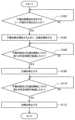
FIG. 13 is a diagram showing an example of the flow of processing executed in thesuction device 100 according to this embodiment.

図13に示すように、まず、吸引装置100は、予備加熱開始を指示するユーザ操作が検出されたか否かを判定する(ステップS102)。予備加熱開始を指示するユーザ操作が検出されていないと判定された場合(ステップS102:NO)、処理は再度ステップS102に戻る。予備加熱開始を指示するユーザ操作が検出されたと判定された場合(ステップS102:NO)、吸引装置100は、加熱部121による予備加熱を開始すると共に、圧縮部160による圧縮を開始する(ステップS104)。 As shown in FIG. 13, first, thesuction device 100 determines whether or not a user operation instructing the start of preheating has been detected (step S102). If it is determined that the user's operation instructing the start of preheating has not been detected (step S102: NO), the process returns to step S102 again. When it is determined that a user operation instructing the start of preheating has been detected (step S102: NO), thesuction device 100 starts preheating by theheating unit 121 and starts compression by the compression unit 160 (step S104). ).

次いで、吸引装置100は、予備加熱及び圧縮を開始してから第1の所定時間が経過したか否かを判定する(ステップS106)。第1の所定時間が経過していないと判定された場合(ステップS106:NO)、処理は再度ステップS106に戻る。第1の所定時間が経過したと判定された場合(ステップS106:YES)、吸引装置100は、圧縮部160による圧縮を停止する(ステップS108)。なお、第1の所定時間は、圧縮時間に関する実験結果に基づいて任意に設定可能である。 Next, thesuction device 100 determines whether or not a first predetermined period of time has elapsed after starting preheating and compression (step S106). If it is determined that the first predetermined time has not elapsed (step S106: NO), the process returns to step S106 again. When it is determined that the first predetermined time has passed (step S106: YES), thesuction device 100 stops compression by the compression section 160 (step S108). Note that the first predetermined time can be arbitrarily set based on experimental results regarding the compression time.

次に、吸引装置100は、予備加熱及び圧縮を開始してから第2の所定時間が経過したか否かを判定する(ステップS110)。第2の所定時間が経過していないと判定された場合(ステップS110:NO)、処理は再度ステップS110に戻る。第2の所定時間が経過したと判定された場合(ステップS110:YES)、吸引装置100は、加熱部121による加熱を停止する(ステップS112)。第2の所定時間は、一例として、第1の所定時間以上の値として任意に設定可能である。 Next, thesuction device 100 determines whether or not a second predetermined period of time has elapsed after starting preheating and compression (step S110). If it is determined that the second predetermined time has not passed (step S110: NO), the process returns to step S110 again. When it is determined that the second predetermined time has passed (step S110: YES), thesuction device 100 stops heating by the heating unit 121 (step S112). As an example, the second predetermined time can be arbitrarily set as a value equal to or longer than the first predetermined time.

<<5.補足>>
以上、添付図面を参照しながら本発明の好適な実施形態について詳細に説明したが、本発明はかかる例に限定されない。本発明の属する技術の分野における通常の知識を有する者であれば、請求の範囲に記載された技術的思想の範疇内において、各種の変更例または修正例に想到し得ることは明らかであり、これらについても、当然に本発明の技術的範囲に属するものと了解される。
<<5. Supplement >>
Although the preferred embodiments of the present invention have been described in detail above with reference to the accompanying drawings, the present invention is not limited to such examples. It is obvious that a person having ordinary knowledge in the technical field to which the present invention belongs can conceive of various modifications or modifications within the scope of the technical idea described in the claims. It is understood that these also belong to the technical scope of the present invention.

例えば、上記実施形態では、爪部161の先端形状の一例として、凸型の円弧形状及び凹型の円弧形状を挙げたが、本発明はかかる例に限定されない。例えば、爪部161の先端形状は、平面であってもよいし、球体であってもよい。また、爪部161の寸法は、上記表1及び表2に示した例に限定されない。例えば、表1及び表2に示した各種寸法は、比率を固定しながら拡縮されてもよい。 For example, in the above-described embodiment, as an example of the tip shape of the claw portion 161, a convex arcuate shape and a concave arcuate shape were given, but the present invention is not limited to such examples. For example, the tip shape of the claw portion 161 may be flat or spherical. Also, the dimensions of the claw portion 161 are not limited to the examples shown in Tables 1 and 2 above. For example, the various dimensions shown in Tables 1 and 2 may be scaled proportionally.

例えば、上記では、加熱時の加熱部121の温度を350°Cとした実験結果について説明したが、加熱時の加熱部121の温度は350℃に限定されない。一例として、加熱時の加熱部121の温度は310℃であってもよい。もちろん、加熱時の加熱部121の温度は、300℃又は320℃等の他の任意の温度であってもよいし、加熱開始からの経過時間に応じて時系列変化してもよい。 For example, in the above description, the experimental results were described in which the temperature of theheating unit 121 during heating was 350°C, but the temperature of theheating unit 121 during heating is not limited to 350°C. As an example, the temperature of theheating unit 121 during heating may be 310°C. Of course, the temperature of theheating unit 121 during heating may be any other temperature such as 300° C. or 320° C., or may change in chronological order according to the elapsed time from the start of heating.

例えば、上記実施形態では、吸引装置100が、圧縮部160による圧縮を開始してから所定時間経過した場合に圧縮部160による圧縮を停止する例を説明したが、本発明はかかる例に限定されない。例えば、吸引装置100は、圧縮部160による圧縮を停止するタイミングを、ユーザがエアロゾルを吸引した回数に基づいて制御してもよい。具体的には、吸引装置100は、パフ回数が所定回数に達するまで圧縮部160による圧縮を継続し、パフ回数が所定回数に達した場合に圧縮部160による圧縮を停止してスティック型基材150を開放してもよい。実験結果を参照しながら上記説明したように、常時圧縮するよりも、圧縮後適切なタイミングで開放した方が、高い昇温効果を得ることができる。その要因のひとつとしては、スティック型基材150を開放することで爪部161への熱伝導が低減し、スティック型基材150の温度が高まることが考えられる。他方、パフ回数が増えるほど、スティック型基材150に含有されるエアロゾル源が消費されて減少し、エアロゾルの生成量が減少していくと考えられる。この点、かかる構成によれば、パフ回数の増加に伴うエアロゾル生成量の低下を、スティック型基材150の開放に起因する昇温に伴うエアロゾル生成量の増加により相殺し、吸引気体内のエアロゾルの成分量の低下を抑制することができる。従って、加熱が開始してからの時間経過に伴う味わいの低下を防ぎ、ユーザの吸引体験の質を向上させることが可能となる。 For example, in the above-described embodiment, thesuction device 100 stops the compression by thecompression unit 160 when a predetermined time has elapsed since the compression by thecompression unit 160 was started, but the present invention is not limited to such an example. . For example, thesuction device 100 may control the timing of stopping compression by thecompression unit 160 based on the number of times the user has sucked the aerosol. Specifically, thesuction device 100 continues the compression by thecompression unit 160 until the number of puffs reaches a predetermined number, and when the number of puffs reaches the predetermined number, stops the compression by thecompression unit 160 and stick-type base material. 150 may be opened. As described above with reference to the experimental results, it is possible to obtain a higher temperature raising effect by releasing the compression at an appropriate timing than by compressing it all the time. One of the reasons for this is that the release of the stick-shapedbase material 150 reduces the heat conduction to the claw portion 161 and increases the temperature of the stick-shapedbase material 150 . On the other hand, it is thought that as the number of puffs increases, the aerosol source contained in the stick-type substrate 150 is consumed and reduced, and the amount of aerosol generated decreases. In this regard, according to this configuration, the decrease in the amount of aerosol generated due to the increase in the number of puffs is offset by the increase in the amount of aerosol generated due to the temperature rise caused by the opening of the stick-type substrate 150, and the aerosol in the suction gas It is possible to suppress the decrease in the amount of the component of. Therefore, it is possible to prevent the taste from deteriorating with the lapse of time from the start of heating, and improve the quality of the user's inhalation experience.

なお、本明細書において説明した各装置による一連の処理は、ソフトウェア、ハードウェア、及びソフトウェアとハードウェアとの組合せのいずれを用いて実現されてもよい。ソフトウェアを構成するプログラムは、例えば、各装置の内部又は外部に設けられる記録媒体(非一時的な媒体:non-transitory media)に予め格納される。そして、各プログラムは、例えば、コンピュータによる実行時にRAMに読み込まれ、CPUなどのプロセッサにより実行される。上記記録媒体は、例えば、磁気ディスク、光ディスク、光磁気ディスク、フラッシュメモリ等である。また、上記のコンピュータプログラムは、記録媒体を用いずに、例えばネットワークを介して配信されてもよい。 A series of processes by each device described in this specification may be realized using any of software, hardware, and a combination of software and hardware. Programs constituting software are stored in advance in a recording medium (non-transitory media) provided inside or outside each device, for example. Each program, for example, is read into a RAM when executed by a computer, and executed by a processor such as a CPU. The recording medium is, for example, a magnetic disk, an optical disk, a magneto-optical disk, a flash memory, or the like. Also, the above computer program may be distributed, for example, via a network without using a recording medium.

また、本明細書においてフローチャート及びシーケンス図を用いて説明した処理は、必ずしも図示された順序で実行されなくてもよい。いくつかの処理ステップは、並列的に実行されてもよい。また、追加的な処理ステップが採用されてもよく、一部の処理ステップが省略されてもよい。 Also, the processes described in this specification using flowcharts and sequence diagrams do not necessarily have to be executed in the illustrated order. Some processing steps may be performed in parallel. Also, additional processing steps may be employed, and some processing steps may be omitted.

100 吸引装置
111 電源部
112 センサ部
113 通知部
114 記憶部
115 通信部
116 制御部
121 加熱部
140 保持部
141 内部空間
142 開口
143 底部
150 スティック型基材
151 基材部
152 吸口部
160 圧縮部
161 爪部
162 基部
171 縁部
172 内壁部
173 第1開口部
174 第1回転部
175 第2回転部
176 第2開口部
177 第1底部
178 第2底部
179 内壁面
190 圧縮方向
191 挿抜方向
191A 挿入方向
191B 引抜方向
192 回転方向
192A 右回転方向
192B 左回転方向
100suction device 111power supply unit 112sensor unit 113notification unit 114storage unit 115communication unit 116control unit 121heating unit 140 holdingunit 141internal space 142opening 143bottom 150 stick-shapedbase material 151base material part 152mouthpiece part 160 compression part 161 Claw portion 162Base portion 171Edge portion 172 Inner wall portion 173First opening 174First rotating portion 175 Second rotating portion 176Second opening 177 First bottom 178 Second bottom 179Inner wall surface 190 Compression direction 191 Insertion/extraction direction 191AInsertion direction 191B Extraction direction 192Rotation direction 192ARight rotation direction 192B Left rotation direction

Claims (18)

Translated fromJapanese
基材を加熱することでユーザに吸引されるエアロゾルを生成する吸引装置であって、
前記吸引装置に形成された内部空間に挿入された前記基材の内部に挿入され、前記基材を加熱する加熱部と、
前記基材のうち前記加熱部により加熱される部分である被加熱部分を外周から前記加熱部の方向へ圧縮する圧縮部と、
前記加熱部による加熱及び前記圧縮部による圧縮の、一方の開始に基づいて他方を開始する制御部と、
を備える吸引装置。
A suction device that generates an aerosol to be sucked by a user by heating a substrate,
a heating unit that is inserted into the interior of the substrate inserted into the internal space formed in the suction device and heats the substrate;
a compressing part that compresses a portion of the base material to be heated by the heating part from the outer circumference toward the heating part;
a control unit that starts one of heating by the heating unit and compression by the compression unit based on the start of the other;
suction device.
前記制御部は、前記加熱部による加熱の開始タイミングと前記圧縮部による圧縮の開始タイミングとを一致又は略一致させる、請求項1に記載の吸引装置。 The suction device according to claim 1, wherein the control unit matches or substantially matches the start timing of heating by the heating unit and the start timing of compression by the compression unit. 前記圧縮部は、前記加熱部の方向に移動することで前記基材を圧縮する、請求項1又は2に記載の吸引装置。 The suction device according to claim 1 or 2, wherein the compression section compresses the base material by moving in the direction of the heating section. 前記圧縮部のうち前記加熱部の方向の先端面の断面形状は、凸型である、請求項3に記載の吸引装置。 4. The suction device according to claim 3, wherein a cross-sectional shape of a distal end surface of the compressing portion in the direction of the heating portion is convex. 前記圧縮部のうち前記加熱部の方向の先端面の断面形状は、凸型の円弧形状である、請求項4に記載の吸引装置。 5. The suction device according to claim 4, wherein a cross-sectional shape of a distal end surface of the compressing portion in the direction of the heating portion is a convex circular arc shape. 前記圧縮部のうち前記加熱部の方向の先端面の断面形状は、半径が1mmであり、幅が2mmである、凸型の円弧形状である、請求項5に記載の吸引装置。 6. The suction device according to claim 5, wherein the cross-sectional shape of the distal end surface of the compressing portion in the direction of the heating portion is a convex circular arc shape with a radius of 1 mm and a width of 2 mm. 前記圧縮部のうち前記加熱部の方向の先端面の断面形状は、凹型である、請求項3に記載の吸引装置。 4. The suction device according to claim 3, wherein a cross-sectional shape of a distal end surface of the compressing portion in the direction of the heating portion is concave. 前記圧縮部のうち前記加熱部の方向の先端面の断面形状は、凹型の円弧形状である、請求項7に記載の吸引装置。 8. The suction device according to claim 7, wherein a cross-sectional shape of a distal end surface of the compressing portion in the direction of the heating portion is a concave circular arc shape. 前記圧縮部のうち前記加熱部の方向の先端面の断面形状は、半径が3mmであり、幅が5mmである、凹型の円弧形状である、請求項8に記載の吸引装置。 9. The suction device according to claim 8, wherein the cross-sectional shape of the distal end surface of the compressing portion in the direction of the heating portion is a concave circular arc shape with a radius of 3 mm and a width of 5 mm. 前記圧縮部のうち前記加熱部の方向の先端面の断面形状は、半径が2.5mmであり、幅が5mmである、凹型の円弧形状である、請求項8に記載の吸引装置。 9. The suction device according to claim 8, wherein the cross-sectional shape of the distal end surface of the compressing portion in the direction of the heating portion is a concave circular arc shape with a radius of 2.5 mm and a width of 5 mm. 前記基材の巻径は7.1mmであり、
前記圧縮部による圧縮の際に、前記圧縮部の先端面が前記基材の外周に接触してから移動する長さは、1mm以内である、請求項3~10のいずれか一項に記載の吸引装置。
The winding diameter of the base material is 7.1 mm,
11. The length of movement after the tip surface of the compression part contacts the outer periphery of the base material during compression by the compression part is within 1 mm, according to any one of claims 3 to 10. suction device.
前記吸引装置は、前記圧縮部を3つ有し、
3つの前記圧縮部は、それぞれ異なる3方向から前記基材を圧縮する、請求項3~11のいずれか一項に記載の吸引装置。
The suction device has three compression units,
The suction device according to any one of claims 3 to 11, wherein the three compression parts compress the base material from three different directions.
前記圧縮部は、耐熱素材により形成される、請求項1~12のいずれか一項に記載の吸引装置。 The suction device according to any one of claims 1 to 12, wherein the compressing portion is made of a heat resistant material. 前記制御部は、前記圧縮部による圧縮を開始してから停止するまでの時間を70秒以下にする、請求項1~13のいずれか一項に記載の吸引装置。 The suction device according to any one of claims 1 to 13, wherein the control section sets the time from starting to stopping compression by the compression section to 70 seconds or less. 前記制御部は、前記圧縮部による圧縮を開始してから停止するまでの時間を10秒以下にする、請求項1~13のいずれか一項に記載の吸引装置。 The suction device according to any one of claims 1 to 13, wherein the control section sets the time from starting to stopping compression by the compression section to 10 seconds or less. 前記制御部は、前記圧縮部による圧縮を停止するタイミングを、ユーザがエアロゾルを吸引した回数に基づいて制御する、請求項1~15のいずれか一項に記載の吸引装置。 The suction device according to any one of claims 1 to 15, wherein the control unit controls the timing of stopping the compression by the compression unit based on the number of times the user has sucked the aerosol. 基材を加熱することでユーザに吸引されるエアロゾルを生成する吸引装置であって、
前記吸引装置に形成された内部空間に挿入された前記基材の内部に挿入され、前記基材を加熱する加熱部と、
前記基材のうち前記加熱部により加熱される部分である被加熱部分を外周から前記加熱部の方向へ圧縮する圧縮部と、
を備える前記吸引装置において、
前記加熱部による加熱及び前記圧縮部による圧縮の、一方の開始に基づいて他方を開始すること、
を含む情報処理方法。
A suction device that generates an aerosol to be sucked by a user by heating a substrate,
a heating unit that is inserted into the interior of the substrate inserted into the internal space formed in the suction device and heats the substrate;
a compressing part that compresses a portion of the base material to be heated by the heating part from the outer circumference toward the heating part;
In the suction device comprising
starting one of heating by the heating unit and compression by the compression unit based on the initiation of the other;
Information processing method including.
基材を加熱することでユーザに吸引されるエアロゾルを生成する吸引装置であって、
前記吸引装置に形成された内部空間に挿入された前記基材の内部に挿入され、前記基材を加熱する加熱部と、
前記基材のうち前記加熱部により加熱される部分である被加熱部分を外周から前記加熱部の方向へ圧縮する圧縮部と、
を備える前記吸引装置を制御するコンピュータを、
前記加熱部による加熱及び前記圧縮部による圧縮の、一方の開始に基づいて他方を開始する制御部、
として機能させるためのプログラム。
A suction device that generates an aerosol to be sucked by a user by heating a substrate,
a heating unit that is inserted into the interior of the substrate inserted into the internal space formed in the suction device and heats the substrate;
a compressing part that compresses a portion of the base material to be heated by the heating part from the outer circumference toward the heating part;
a computer that controls the suction device comprising
A control unit that starts one of heating by the heating unit and compression by the compression unit based on the start of the other;
A program to function as
JP2022508092A2020-03-182021-01-19 Suction device, information processing method, and programActiveJP7290796B2 (en)

Applications Claiming Priority (3)

Application NumberPriority DateFiling DateTitle
JP20200471782020-03-18
PCT/JP2021/001651WO2021186880A1 (en)2020-03-182021-01-19Aspiration device, information processing method and program

Publications (2)

Publication NumberPublication Date
JPWO2021186880A1 JPWO2021186880A1 (en)2021-09-23
JP7290796B2true JP7290796B2 (en)2023-06-13

Family

ID=77770818

Family Applications (1)

Application NumberTitlePriority DateFiling Date
JP2022508092AActiveJP7290796B2 (en)2020-03-182021-01-19 Suction device, information processing method, and program

Country Status (4)

CountryLink
EP (1)EP4066657A1 (en)
JP (1)JP7290796B2 (en)
CN (1)CN115038347A (en)
WO (1)WO2021186880A1 (en)

Citations (4)

* Cited by examiner, † Cited by third party
Publication numberPriority datePublication dateAssigneeTitle
JP2014533513A (en)2011-11-212014-12-15フィリップ・モーリス・プロダクツ・ソシエテ・アノニム Extractor for aerosol generator
WO2019081602A1 (en)2017-10-242019-05-02Philip Morris Products S.A.Aerosol-generating device having holding mechanism
WO2019121668A1 (en)2017-12-182019-06-27Jt International SaHeating assembly for a vapour generating device
WO2019140749A1 (en)2018-01-222019-07-25上海新型烟草制品研究院有限公司Releasing mechanism, aerosol generating device, releasing method, and smoke producing article

Family Cites Families (3)

* Cited by examiner, † Cited by third party
Publication numberPriority datePublication dateAssigneeTitle
HUE036091T2 (en)*2012-12-282018-06-28Philip Morris Products SaHeating assembly for an aerosol generating system
RU2704888C2 (en)*2015-06-302019-10-31Филип Моррис Продактс С.А.Aerosol-generating method, device and system with heated gas sensor
KR102586323B1 (en)*2018-04-262023-10-10니뽄 다바코 산교 가부시키가이샤Heater assembly and container

Patent Citations (4)

* Cited by examiner, † Cited by third party
Publication numberPriority datePublication dateAssigneeTitle
JP2014533513A (en)2011-11-212014-12-15フィリップ・モーリス・プロダクツ・ソシエテ・アノニム Extractor for aerosol generator
WO2019081602A1 (en)2017-10-242019-05-02Philip Morris Products S.A.Aerosol-generating device having holding mechanism
WO2019121668A1 (en)2017-12-182019-06-27Jt International SaHeating assembly for a vapour generating device
WO2019140749A1 (en)2018-01-222019-07-25上海新型烟草制品研究院有限公司Releasing mechanism, aerosol generating device, releasing method, and smoke producing article

Also Published As

Publication numberPublication date
WO2021186880A1 (en)2021-09-23
CN115038347A (en)2022-09-09
EP4066657A1 (en)2022-10-05
JPWO2021186880A1 (en)2021-09-23

Similar Documents

PublicationPublication DateTitle
CN106659249B (en) Electronic steam supply system
JP7170118B2 (en) SUCTION DEVICE, CONTROL DEVICE FOR SUCTION DEVICE, INFORMATION PROGRAM AND METHOD
CN113056209B (en)Electronic device, method for operating electronic device, and program
JP2024016120A (en) Aerosol delivery devices and related methods and computer program products for controlling aerosol delivery devices based on input characteristics
US10206428B2 (en)Aerosol-generating system with a replaceable mouthpiece cover
US20220202102A1 (en)An aerosol-generating system and haptic output elements for an aerosol-generating system
CN111031821A (en)Aerosol-generating device with removably inserted heating chamber
KR20140083983A (en)Portable Electronic Vapor-Producing Device and Method
CN108366622A (en)Electrical smoking device with the cavity for liquid storage device
JP7206017B2 (en) Suction device, information processing method, and program
CN113677227A (en)Electronic aerosol supply system
KR20190129757A (en)Fine particle generator
WO2021240617A1 (en)Inhaling device, control method, and program
CN210581007U (en)Electronic atomization device
JP7290796B2 (en) Suction device, information processing method, and program
CN111685370A (en)Cigarette bullet and electron cigarette
RU2797153C1 (en)Inhalation device, information processing performed by an inhalation device, and information carrier
JP7518295B2 (en) Aerosol Generation System
CN217826740U (en)Aerosol generator
JP2019071885A (en)Non-combustible flavor aspirator
WO2023104703A1 (en)An aerosol generating system
EP3689165B1 (en)Smoking substitute device
WO2023188102A1 (en)Aerosol generating device, control method, and program
EP4520206A1 (en)Aerosol delivery system with locked/unlocked modes
TWI859477B (en)Aerosol generation system

Legal Events

DateCodeTitleDescription
A621Written request for application examination

Free format text:JAPANESE INTERMEDIATE CODE: A621

Effective date:20220607

TRDDDecision of grant or rejection written
A01Written decision to grant a patent or to grant a registration (utility model)

Free format text:JAPANESE INTERMEDIATE CODE: A01

Effective date:20230509

A61First payment of annual fees (during grant procedure)

Free format text:JAPANESE INTERMEDIATE CODE: A61

Effective date:20230601

R150Certificate of patent or registration of utility model

Ref document number:7290796

Country of ref document:JP

Free format text:JAPANESE INTERMEDIATE CODE: R150


[8]ページ先頭

©2009-2025 Movatter.jp