JP7287703B1 - Telemetry device, telemetry system, telemetry method, and program - Google Patents
Telemetry device, telemetry system, telemetry method, and programDownload PDFInfo
- Publication number
- JP7287703B1 JP7287703B1JP2021210779AJP2021210779AJP7287703B1JP 7287703 B1JP7287703 B1JP 7287703B1JP 2021210779 AJP2021210779 AJP 2021210779AJP 2021210779 AJP2021210779 AJP 2021210779AJP 7287703 B1JP7287703 B1JP 7287703B1
- Authority
- JP
- Japan
- Prior art keywords
- unit
- failure
- measurement data
- telemetry
- signal
- Prior art date
- Legal status (The legal status is an assumption and is not a legal conclusion. Google has not performed a legal analysis and makes no representation as to the accuracy of the status listed.)
- Active
Links
- 238000000034methodMethods0.000titleclaimsdescription21
- 238000004891communicationMethods0.000claimsabstractdescription87
- 238000005259measurementMethods0.000claimsdescription62
- 238000003745diagnosisMethods0.000claimsdescription18
- 230000008569processEffects0.000claimsdescription12
- 230000005540biological transmissionEffects0.000claimsdescription7
- 238000013500data storageMethods0.000claimsdescription5
- 238000010586diagramMethods0.000description17
- 230000006870functionEffects0.000description14
- 238000012545processingMethods0.000description14
- 230000006866deteriorationEffects0.000description9
- 230000000694effectsEffects0.000description5
- 238000005516engineering processMethods0.000description5
- 238000011156evaluationMethods0.000description5
- 230000003287optical effectEffects0.000description3
- 238000011084recoveryMethods0.000description3
- 230000007704transitionEffects0.000description3
- 238000013210evaluation modelMethods0.000description2
- 238000012986modificationMethods0.000description2
- 230000004048modificationEffects0.000description2
- 238000012544monitoring processMethods0.000description2
- 239000013307optical fiberSubstances0.000description2
- 238000003908quality control methodMethods0.000description2
- 239000004065semiconductorSubstances0.000description2
- XLYOFNOQVPJJNP-UHFFFAOYSA-NwaterSubstancesOXLYOFNOQVPJJNP-UHFFFAOYSA-N0.000description2
- 238000012935AveragingMethods0.000description1
- 238000004458analytical methodMethods0.000description1
- 230000008859changeEffects0.000description1
- 238000004590computer programMethods0.000description1
- 238000012937correctionMethods0.000description1
- 238000013480data collectionMethods0.000description1
- 238000013523data managementMethods0.000description1
- 230000002950deficientEffects0.000description1
- 238000012217deletionMethods0.000description1
- 230000037430deletionEffects0.000description1
- 230000002542deteriorative effectEffects0.000description1
- 238000011161developmentMethods0.000description1
- 230000007613environmental effectEffects0.000description1
- 230000002349favourable effectEffects0.000description1
- 230000010365information processingEffects0.000description1
- 238000007689inspectionMethods0.000description1
- 238000009434installationMethods0.000description1
- 239000004973liquid crystal related substanceSubstances0.000description1
- 238000007726management methodMethods0.000description1
- 239000010865sewageSubstances0.000description1
- 239000008399tap waterSubstances0.000description1
- 235000020679tap waterNutrition0.000description1
- 230000001052transient effectEffects0.000description1
Images


Landscapes
- Selective Calling Equipment (AREA)
- Mobile Radio Communication Systems (AREA)
Abstract
Translated fromJapaneseDescription
Translated fromJapanese本発明は、遠隔測定装置、遠隔測定システム、遠隔測定方法、及びプログラムに関する。 The present invention relates to a telemetry device, a telemetry system, a telemetry method, and a program.
通信の発達により、遠隔測定(テレメータリング)技術の適用例が増加している。とりわけ、電力、ガス、水道といったインフラの分野において遠隔測定技術が活用されており、なかでも、スマートメータによる検針システムがその代表例として挙げられる。 The development of communications has led to increasing applications of telemetry technology. In particular, telemetry technology is utilized in the field of infrastructure such as electric power, gas, and water supply, and a typical example is a meter reading system using a smart meter.
スマートメータによる検針システムの一例として、個々の家庭に取り付けた検針メータからの検針データを無線技術で送信する手段を設ける無線子機と、その無線子機からの検針メータの検針データを集約する集線装置によって実現されるシステムがある。集線装置は無線子機から集約された検針データを光ファイバ網等の通信網を介して上位検針サーバに送信し、送信された検針データは最終的に中央のサーバに集約される。 As an example of a meter reading system using a smart meter, there is a wireless slave device equipped with a means for transmitting meter reading data from meter reading meters installed in individual homes using wireless technology, and a line concentrator that collects the meter reading data from the wireless slave device. There are systems implemented by devices. The line concentrator transmits the meter reading data collected from the wireless slave units to the host meter reading server via a communication network such as an optical fiber network, and the transmitted meter reading data is finally collected in the central server.
検針メータは各戸に設置されることから一つの集線装置に接続される無線子機は、多数に及ぶ場合がある。一方、無線による通信により集線装置に検針データが送られるため、電波状態の悪化や通信子機等の故障等を原因として一時的に通信状態が悪化する場合がある。 Since a meter reading meter is installed in each house, a large number of wireless slave units may be connected to one line concentrator. On the other hand, since the meter reading data is sent to the line concentrator by wireless communication, the communication state may deteriorate temporarily due to deterioration of the radio wave state, failure of the communication slave unit, or the like.
特許文献1には、マルチホップネットワークを構成する端末装置からデータを収集する中央処理装置の発明が開示されている。該技術は、中央処理装置は端末装置から定期的に送信されるデータを受信する。受信されたデータにはネットワーク経路内の通信品質を示す情報が含まれており、これを記憶する。通信状態が悪化してデータ収集によるデータの欠落が生じた場合には、再収集処理を実施する。再収集処理にも失敗した場合には、記憶されている通信品質を示す情報に基づいて、次回の収集時間帯よりも通信品質がより良好な時間帯が存在するかを判定し、より良好な時間帯が存在するとの判断結果となった場合には、その良好な時間帯に収集するように収集スケジュールを変更するといった処理が可能である。
なお、上記先行技術文献の各開示を、本書に引用をもって繰り込むものとする。以下の分析は、本発明者らによってなされたものである。 In addition, each disclosure of the above prior art documents is incorporated into this document by reference. The following analysis was made by the inventors.
しかしながら、上記開示された発明は、通信状態が悪化してデータの受信に失敗すると中央処理装置はデータの再収集処理を試みるが、端末装置及び中央処理装置には故障診断機能を有していないため、データの再収集が、単に一時的な電波状況の悪化による通信の失敗に起因するものなのか、あるいは端末装置の故障による通信の失敗に起因するものなのか、知る術がなかった。 However, in the above-disclosed invention, when the communication state deteriorates and data reception fails, the central processing unit attempts data recollection processing, but the terminal unit and central processing unit do not have a failure diagnosis function. Therefore, there was no way to know whether the re-collection of data was caused by a communication failure due to a temporary deterioration of radio wave conditions, or a communication failure due to a failure of the terminal device.
また、端末装置に故障診断機能などの比較的高度な機能を搭載すると、上記のような非常に多数のスマートメータを用いた検針システムにおいては著しいコストの増大を招くこととなる。 Moreover, if a relatively advanced function such as a fault diagnosis function is installed in the terminal device, the cost of the meter reading system using a large number of smart meters as described above will increase significantly.
本発明は、端末装置の通信機能故障を端末装置自体が検出しなくても、端末装置の通信機能の故障の検出及び予測等の診断が可能な遠隔測定装置、遠隔測定システム、遠隔測定方法及びプログラムを提供することを主たる目的とする。 The present invention provides a telemetry device, a telemetry system, a telemetry method, and a telemetry device capable of detecting and diagnosing a failure of a communication function of a terminal device even if the terminal device itself does not detect the failure of the communication function of the terminal device. The main purpose is to provide programs.
本発明乃至開示の第一の視点によれば、測定器からの測定データを受信する受信部と、前記受信部にて前記測定データを受信した際の信号状態を取得する信号状態取得部と、前記信号状態に基づいて前記測定器の故障を診断する診断部と、を有する遠隔測定装置が提供される。 According to a first aspect of the present invention or disclosure, a receiving unit that receives measurement data from a measuring device, a signal state acquisition unit that acquires a signal state when the measurement data is received by the reception unit, and a diagnostic component for diagnosing faults in the meter based on the signal state.
本発明乃至開示の第二の視点によれば、対象を測定する測定部と、前記測定部で測定された測定データを送信する送信部と、を有する測定器と、前記測定器からの前記測定データを受信する受信部と、前記受信部にて前記測定データを受信した際の信号状態を取得する信号状態取得部と、前記信号状態に基づいて前記測定器の故障を診断する診断部と、を有する遠隔測定装置と、を含む遠隔測定システムが提供される。 According to a second aspect of the present invention or disclosure, a measuring device including a measuring unit that measures an object and a transmitting unit that transmits measurement data measured by the measuring unit; a receiving unit for receiving data, a signal state acquisition unit for acquiring a signal state when the measurement data is received by the receiving unit, a diagnostic unit for diagnosing a failure of the measuring device based on the signal state, A telemetry system is provided that includes a telemetry device having a.
本発明乃至開示の第三の視点によれば測定器からの測定データを受信する受信ステップと、前記測定データを受信した際の信号状態を取得する信号状態取得ステップと、前記信号状態に基づいて前記測定器の故障を診断する故障診断ステップと、を有する遠隔測定方法が提供される。 According to a third aspect of the present invention or disclosure, a receiving step of receiving measured data from a measuring device, a signal state obtaining step of obtaining a signal state when the measured data is received, and based on the signal state and a fault diagnosis step of diagnosing faults in the meter.
本発明乃至開示の第四の視点によれば測定器からの測定データを受信する処理と、前記測定データを受信した際の信号状態を取得する処理と、前記信号状態に基づいて前記測定器の故障を診断する処理と、をコンピュータで実行させるためのプログラムが提供される。なお、このプログラムは、コンピュータが読み取り可能な記憶媒体に記録することができる。記憶媒体は、半導体メモリ、ハードディスク、磁気記録媒体、光記録媒体等の非トランジェント(non-transient)なものとすることができる。本発明は、コンピュータプログラム製品として具現することも可能である。 According to a fourth aspect of the present invention or disclosure, a process of receiving measurement data from a measuring device, a process of acquiring a signal state when the measurement data is received, and a processing of the measuring device based on the signal state A program is provided for causing a computer to execute a process of diagnosing a failure. This program can be recorded in a computer-readable storage medium. The storage medium can be non-transient such as semiconductor memory, hard disk, magnetic recording medium, optical recording medium, and the like. The invention can also be embodied as a computer program product.
本発明乃至開示の各視点によれば、端末装置の通信機能故障を端末装置自体が検出しなくても、端末装置の通信機能の故障の検出及び予測等の診断が可能な遠隔測定装置、遠隔測定システム、遠隔測定方法及びプログラムが提供される。 According to each aspect of the present invention and the disclosure, a telemetry device capable of detecting and diagnosing a failure of a communication function of a terminal device even if the terminal device itself does not detect the failure of the communication function of the terminal device; A measurement system, telemetry method and program are provided.
初めに、一実施形態の概要について説明する。なお、この概要に付記した図面参照符号は、理解を助けるための一例として各要素に便宜上付記したものであり、この概要の記載はなんらの限定を意図するものではない。また、各図におけるブロック間の接続線は、双方向及び単方向の双方を含む。一方向矢印については、主たる信号(データ)の流れを模式的に示すものであり、双方向性を排除するものではない。さらに、本願開示に示す回路図、ブロック図、内部構成図、接続図などにおいて、明示は省略するが、入力ポート及び出力ポートが各接続線の入力端及び出力端のそれぞれに存在する。入出力インタフェースも同様である。 First, an overview of one embodiment will be described. It should be noted that the drawing reference numerals added to this outline are added to each element for convenience as an example to aid understanding, and the description of this outline does not intend any limitation. Also, connecting lines between blocks in each figure include both bi-directional and uni-directional. The unidirectional arrows schematically show the flow of main signals (data) and do not exclude bidirectionality. Furthermore, in the circuit diagrams, block diagrams, internal configuration diagrams, connection diagrams, etc. disclosed in the present application, an input port and an output port exist at the input end and the output end of each connection line, respectively, although not explicitly shown. The input/output interface is the same.
図1は一実施形態に係る遠隔測定装置の構成の一例を示すブロック図である。この図にあるように、一実施形態に係る遠隔測定装置10は、受信部11と、信号状態取得部12と、診断部13と、を有する。 FIG. 1 is a block diagram showing an example of the configuration of a telemetry device according to one embodiment. As shown in this figure, a
受信部11は、測定器からの測定結果を測定データとして受信する。「測定器」は、測定対象を測定し、測定結果を測定データとして受信部11へ送信する。「受信」とは通信により測定データを電気信号で取得することを指す。通信は既存の通信方式によるものであってよく、無線又は有線の別を問わない。受信部11は取得した電気信号をデータに復号し、データを処理したり記憶したりするモジュールに渡す。測定器は複数存在してよく、複数の測定器が本願発明の遠隔測定装置10に接続されていてもよい。 The
信号状態取得部12は受信部11にて測定データを受信した際の信号状態を取得する。「信号」とはデータを搬送する電気信号を一般的に指すものであるが、本願発明では「信号」とは信号から復調された符号や、符号から構成されるデータ等も「信号」に含まれるものとする。「信号状態」とは入力信号の強さといった物理的な低レイヤの状態から信号波形の歪、あるいは誤り訂正の発生頻度、遅延、スループット等のソフトウエアモジュールが介在するような比較的高レイヤの状態のいずれをも含む。信号状態の取得は、当部が信号を傍受して取得してもよいし、受信部11で受信した信号を当部が入力として受取り、状態の取得を実行してもよい。あるいは一定の種類の信号状態は受信部11で取得し、その他の信号状態については当部が取得してもよい。いずれにおいても取得された信号状態は信号状態データとして当部を介して後述する診断部13に出力される。 The signal
診断部13は信号状態に基づいて測定器の故障を診断する。「故障を診断」とは現在の信号状態を把握して評価した結果、故障であるか否かを診断することと、現在の状態をもとに将来の故障の可能性について評価し診断することとを少なくとも含む。故障であるか否かの診断については、例えばある時点における信号状態を示す指標値が閾値を超過した場合等の即時的な評価結果であってよいし、所定の状態が一定時間以上継続した場合等の経時的な評価結果であってもよい。また、例えば単に一つの指標を評価する評価方法であってもよいし、数々の指標を評価モデルにより総合的に評価する評価方法であってもよい。さらに例えば、上記評価モデルは評価結果に対して実際の故障の有無等をフィードバックすることでパラメータを変更し、学習することが可能であってもよい。
診断結果については故障か否かの判断結果の他に、故障の予兆の有無や、故障に至るまでの時間等を出力するものであってもよい。また、少なくとも一の測定器の故障診断結果をもとに、他の測定器(群)の故障について予測する構成であってもよい。この場合においては、例えば測定器の設置位置や標高、動作温度などの環境的要因を示す指標をデータとして取得し、取得されたデータを用いて故障が検出された一の測定器と似た環境にある測定機の故障の予測をしたり、監視レベルを上げたりといった処理を実行してもよい。 As for the diagnosis result, in addition to the result of determining whether or not there is a failure, the presence or absence of a sign of failure, the time until failure, and the like may be output. Further, a configuration may be adopted in which failures of other measuring instruments (groups) are predicted based on the failure diagnosis result of at least one measuring instrument. In this case, for example, indicators indicating environmental factors such as the installation position, altitude, and operating temperature of the measuring instrument are acquired as data, and the acquired data is used to identify an environment similar to that of the one measuring instrument in which the failure was detected. It is also possible to predict a failure of a measuring instrument in the system or to raise the monitoring level.
以下に具体的な実施の形態について、図面を参照してさらに詳しく説明する。なお、各実施形態において同一構成要素には同一の符号を付し、その説明を省略する。 Specific embodiments will be described in more detail below with reference to the drawings. In addition, the same code|symbol is attached|subjected to the same component in each embodiment, and the description is abbreviate|omitted.
[第1の実施形態]
第1の実施形態について、図面を用いてより詳細に説明する。図2は第1の実施形態における遠隔測定装置10の構成の一例を示すブロック図である。[First Embodiment]
The first embodiment will be described in more detail with reference to the drawings. FIG. 2 is a block diagram showing an example of the configuration of the
本実施形態の遠隔測定装置10は下記の構成を有する。すなわち、第1の実施形態に係る遠隔測定装置10は、図2に示す通り、受信部11と、信号状態取得部12と、診断部13と、故障判定部14と、通知部15と、故障予測部16と、を有する。本実施形態の遠隔測定装置10の上記一実施形態との構成上の差異は、新たに故障判定部14と、通知部15と、故障予測部16とを有する点である。 The
信号状態取得部12は、信号状態として少なくとも信号強度と、信号の誤り率とを取得してもよい。診断部13は取得された信号強度と、信号の誤り率とを用いて測定器の故障を診断してもよい。「信号強度」と「信号の誤り率」に関しては既存の種々の指標が採用できる。 The signal
「信号強度」の指標としては、遠隔測定装置10が測定器と無線による通信を行う場合には電波強度(RSSI:Received Signal Strength Indicator)などが採用できる。また「信号の誤り率」の指標としてはフレーム誤り率(FER:Frame Error Rate)、ビット誤り率(BER:Bit Error Rate)、ブロック誤り率(BLER:Block Error Rate)などが採用できる。これらの指標は一例であり、これらに限定されるものではない。 As an indicator of "signal strength", when the
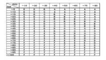
診断部13はさらに、取得された信号強度と信号の誤り率とを用いて通信品質をランキングしてもよい。ここで「ランキング」とは、電波の品質を一の指標、又は複数の指標を組み合わせて評価した結果を階級化したものである。図3はRSSIとFERの値の組み合わせによるランキングの一例である。この図にあるようにRSSI(8階級)とFER(20階級)の値を階級化し、その階級の組み合わせによりAからFまでのランキングが生成されている。このように指標それぞれに異なる階級数を設定することで、各指標に最適化された階級数(観測の粒度)を決めることが可能である。これによりAからFの6段階のランキングの有意性を高めることができる。 The
故障判定部14はランキングに基づいて、前記測定器の故障を判定する。診断部13により生成されたランキングデータを取得して、ランキングから故障であるか否かの判定を行う。判定は種々の基準にて行うことが可能である。例えばある時点でランキングE、Fが付与された場合には故障であるとの判定をすることができ、作業員を点検のため派遣することを検討するといった対応等を行うことができる。また例えばランキングC、Dに関しては故障の可能性が高いとの判定をすることができ、監視レベルを上げるため、信号状態取得部12により信号状態を取得する頻度を高めるといった対応等を行うことができる。 A
故障判定の基準はランキングのある時点の値だけでなく、ランキングの推移に基づくものであってもよい。具体的には例えば過去3回のランキングがCであった後にD、Eにランキングが移行した場合には経年劣化による故障であるとの推定を行うことが可能である。また前回信号状態を取得した際においてはランキングがAであったものが今回はランキングDに急落しているとする。この場合には経年劣化によるものでなく突発的な事態による通信環境の悪化が推定され、次回の信号状態取得のランキング如何により故障の判定を行うとして引き続き監視対象とする等の対応を取ることができる。 The failure determination criteria may be based not only on the value of the ranking at a certain point in time, but also on the transition of the ranking. Specifically, for example, when the ranking shifts to D and E after being ranked C three times in the past, it is possible to presume that the failure is due to deterioration over time. It is also assumed that the ranking that was A when the signal state was obtained last time has dropped to D in this time. In this case, it is presumed that the deterioration of the communication environment is not due to deterioration over time, but due to a sudden event. can.
故障判定部14は、上記故障であるとの判定に加え、故障との判定結果となった測定器の復旧を判定する。前回のランキングでAからEに急落した測定器があったとして、今回の信号状態のランキングはBに回復した場合には一時的な事情(例えば降雨などの天候等)で通信環境が悪化していたということが推定でき、測定器が復旧したとの判定を実行することが可能である。 In addition to the determination that there is a failure, the
故障判定部14における判定結果は後述する通知部15に対して送られる。 The determination result of the
故障予測部16は、ランキングに基づいて、測定器の故障を予測する。故障にまだ至っていないものの、故障の予兆をランキングの推移等から捕捉するための処理を実行する。例えばランキングでBが続いていた測定器がCに移行した時には経年劣化による故障の予兆があるとの予測結果を出力する。予測結果は通知部15に出力する。 A
通知部15は、測定器が故障である旨の判定結果を通知する。また、通知部15は、測定器が復旧した旨の判定結果を通知する。さらに通知部15は、故障が予測されている旨の予測結果を通知する。通知の方法は、遠隔測定装置10のディスプレイ等の表示出力デバイスにメッセージを表示する他、遠隔測定装置10に接続された端末の表示出力デバイスにメッセージを表示する等が考えられる。また、E-Mailやメッセンジャーなどを介して通知を行ってもよい。 The
[動作の説明]
本実施形態の遠隔測定装置10の動作の一例について図4を用いて説明する。図4は、第1の実施形態に係る遠隔測定装置10の動作の一例を示すフローチャートである。[Explanation of operation]
An example of the operation of the
同装置が動作を開始すると、測定器からのデータを受信する(ステップS40、Y)。データを受信すると信号状態(例えば信号強度や誤り率)を取得する(ステップS41)。次に、取得された信号状態(例えば信号強度や誤り率)を用いて通信品質をランキングする(ステップS42)。その後、ランキングに基づいて測定器が故障中であるか否かを判定する(ステップS43)。判定の結果、測定器が故障中であるとの判定結果(Y)となった場合には、故障の旨通知する(ステップS44)。 When the device starts operating, it receives data from the measuring device (step S40, Y). When data is received, the signal state (for example, signal strength and error rate) is acquired (step S41). Next, the communication quality is ranked using the obtained signal state (for example, signal strength and error rate) (step S42). After that, it is determined whether or not the measuring device is out of order based on the ranking (step S43). As a result of the determination, if the determination result (Y) is that the measuring device is out of order, the failure is notified (step S44).
判定の結果、測定器が故障中ではないとの判定結果(N)となった場合には、測定器の故障が予測されているか否かを判定する(ステップS45)。測定器の故障が予測されている場合(Y)には、故障が予測されている旨の通知を行う(ステップS46)。測定器の故障が予測されていない場合(N)には測定器が復旧しているか否かを判定する(ステップS47)。なおこの処理の前に故障している測定器が存在しているか否かを判定する処理が実行されてもよい。測定器が復旧している場合(Y)には復旧の旨を通知する(ステップS48)。測定器が復旧していない場合(N)には引き続き測定器からデータを受信する(ステップS40)。通知(ステップS44、ステップS46、ステップS48)後においては動作が終了(ステップS49、Y)するまで引き続き測定器からデータを受信する処理に戻る(ステップS49、N)。 If the result of determination is that the measuring device is not out of order (N), it is determined whether or not the measuring device is predicted to be out of order (step S45). If the failure of the measuring device is predicted (Y), notification to the effect that the failure is predicted is provided (step S46). If the failure of the measuring device is not predicted (N), it is determined whether or not the measuring device has recovered (step S47). Before this process, a process of determining whether or not there is a malfunctioning measuring device may be executed. If the measuring device has been restored (Y), the restoration is notified (step S48). If the measuring device is not restored (N), data is continuously received from the measuring device (step S40). After notification (step S44, step S46, step S48), the process continues to receive data from the measuring device until the operation is completed (step S49, Y) (step S49, N).
[ハードウエア構成]
遠隔測定装置10は、情報処理装置(コンピュータ)により構成可能であり、図5に例示する構成を備える。例えば、遠隔測定装置10は、内部バス56により相互に接続される、CPU(Central Processing Unit)51、メモリ52、入出力インタフェース53及び通信手段である無線通信モジュール54等を備える。無線通信モジュール54にはアンテナ55が接続されている。[Hardware configuration]
The
但し、図5に示す構成は、遠隔測定装置10のハードウエア構成を限定する趣旨ではない。遠隔測定装置10は、図示しないハードウエアを含んでもよいし、必要に応じて入出力インタフェース53を備えていなくともよい。また、遠隔測定装置10に含まれるCPU等の数も図5の例示に限定する趣旨ではなく、例えば、複数のCPUが遠隔測定装置10に含まれていてもよい。 However, the configuration shown in FIG. 5 is not meant to limit the hardware configuration of the
メモリ52は、RAM(Random Access Memory)、ROM(Read Only Memory)、補助記憶装置(ハードディスク等)である。 The
入出力インタフェース53は、図示しない表示装置や入力装置のインタフェースとなる手段である。表示装置は、例えば、液晶ディスプレイ等である。入力装置は、例えば、キーボードやマウス等のユーザ操作を受け付ける装置である。 The input/
遠隔測定装置10の機能は、メモリ52に格納された受信プログラム、信号状態取得プログラム、診断プログラム、故障判定プログラム、故障予測プログラム、通知プログラム、等といったプログラム群(処理モジュール)と、測定器からの測定データ、信号状態(信号強度の値と誤り率の値とを含む)、が含まれるデータ群により実現される。当該処理モジュールは、例えば、メモリ52に格納された各プログラムをCPU51が実行することで実現される。また、そのプログラムは、ネットワークを介してダウンロードするか、あるいは、プログラムを記憶した記憶媒体を用いて、更新することができる。さらに、上記処理モジュールは、半導体チップにより実現されてもよい。即ち、上記処理モジュールが行う機能を何らかのハードウエア、及び/又は、ソフトウエアで実行する手段があればよい。 The functions of the
[ハードウエアの動作]
遠隔測定装置10は、動作を開始すると、受信プログラムがメモリ52から呼び出され、CPU51で実行状態となる。同プログラムは測定器から送信された測定データを無線通信モジュール54で受信する。[Hardware operation]
When the
次に信号状態取得プログラムがメモリ52から呼び出され、CPU51にて実行状態となる。同プログラムは無線通信モジュール54における通信の状態を示す値を所定のタイミングで取得する。具体的にはRSSIやFERの値等を無線通信モジュール54から取得する。同プログラムは遠隔測定装置10の動作中は常に常駐し、通信状態を示す値を取得しメモリ52へ格納する。 Next, the signal state acquisition program is called from the
次に、診断プログラムがメモリ52から呼び出され、CPU51にて実行状態となる。同プログラムは信号状態取得プログラムにより取得され、メモリ52に格納された通信状態を示す値を取得する。同プログラムは取得された通信状態を示す値を所定のルールでランクを示す値に変換する。 Next, the diagnostic program is called from the
次に、故障判定プログラムがメモリ52から呼び出され、CPU51にて実行状態となる。同プログラムは診断プログラムにおいて変換されたランクを示す値を読み込み、所定のルールで故障判定を行う。故障判定の結果、故障であるとの判定結果が出力された場合には、通知プログラムをメモリ52から呼び出し、CPU51にて実行状態とする。同プログラムは、故障であるとの判定結果を、ディスプレイ等の入出力インタフェース53により出力する。なお、同プログラムは判定結果を無線通信モジュール54や図示しないNIC(Network Interface Card)等を介して他の端末に送信してもよい。 Next, the failure determination program is called from the
故障判定の結果、故障でないとの判定結果が出力された場合には、次に故障予測プログラムをメモリ52から呼び出し、CPU51にて実行状態とする。同プログラムは、診断プログラムにおいて変換されたランクを示す値を所定のルールで判定を行い、故障が予測される状態か否かを判定する。故障予測判定の結果、故障が予測されるとの判定結果が得られた場合には、通知プログラムや入出力インタフェース53等により判定結果を通知する。 As a result of the failure determination, if the result of determination that there is no failure is output, then the failure prediction program is called from the
故障が予測されないとの判定結果が得られた場合には、すでに実行状態となっている故障判定プログラムがすでに故障状態であった測定器が存在した場合に診断プログラムによるランクを示す値を用いて所定のルールにより故障が復旧したか否かの判断を行う。その結果、復旧したとの判定結果が得られた場合にはその旨の通知を通知プログラム等により通知する。復旧したとの判定結果が得られない場合には引き続き受信プログラムにより測定データを受信し、信号状態取得プログラムにより信号状態を示す値が取得される。 If the determination result indicates that a failure is not predicted, the value indicating the rank by the diagnostic program is used when there is a measuring instrument for which the failure determination program that has already been executed is already in the failure state. It is determined whether or not the fault has been recovered according to a predetermined rule. As a result, when the determination result that the system has been restored is obtained, a notification to that effect is notified by a notification program or the like. If the determination result of recovery is not obtained, the reception program continues to receive the measurement data, and the signal state acquisition program acquires a value indicating the signal state.
[効果の説明]
上記第1の実施形態に係る遠隔測定装置により、通信状態を示す値を取得し、通信状態をランキングすることが可能である。ランキングの推移により測定器の状態を判定することが可能である。具体的には測定器が故障あるいは故障が予測される状態であるかを判定により検出することが可能となる。これにより測定器自体に故障を診断する機能を有しなくても遠隔測定装置の側で測定器の故障又は故障に至る状態を発見することが可能である。[Explanation of effect]
With the telemetry device according to the first embodiment, it is possible to obtain a value indicating the communication state and rank the communication state. It is possible to determine the state of the measuring device from the transition of the ranking. Specifically, it is possible to detect by determination whether the measuring device is in a state of failure or failure is predicted. This makes it possible for the telemetry device to discover failures or conditions leading to failures of the measuring device even if the measuring device itself does not have a function for diagnosing failures.
[第2の実施形態]
第2の実施形態では、複数の測定器20-1ないし20-nと、遠隔測定装置10と、測定データを受信し格納するサーバ装置30と、を含む遠隔測定システムについて説明する。図6は第2の実施形態に係る遠隔測定システムの構成の一例を示すブロック図である。[Second embodiment]
In a second embodiment, a telemetry system is described that includes a plurality of meters 20-1 through 20-n, a
複数の測定器20-1ないし20-nは、測定部21と、前記測定部で測定された測定データを遠隔測定装置10に送信する送信部22とをそれぞれ有する。 A plurality of measuring devices 20-1 to 20-n each have a measuring
遠隔測定装置10は、測定器20-1ないし20-nからの測定データを受信する受信部11と、受信部11にて測定データを受信した際の信号状態を取得する信号状態取得部12と、信号状態に基づいて測定器20-1ないし20-nの故障を診断する診断部13と、を有する。これら構成要素については上記で説明済みであるので記載は省略する。本実施形態の遠隔測定システムの遠隔測定装置10は、さらに測定器20-1ないし20-nからの測定データをサーバ装置30に対して送信する測定データ送信部17を有する。 The
ここで本システムにおいて遠隔測定装置10が複数含まれていてよい。複数の測定器20-1ないし20-nはグループ化されてグループ毎にそれぞれ複数の遠隔測定装置10と接続されていてもよい。 Here,
測定部21は測定器20-1ないし20-nにおいて対象を測定する。「対象」とは例えば電力量、ガス流量、水道水及び下水道水の流量などが含まれる。送信部22は測定器20-1ないし20-nにおいて測定部21にて測定された測定データを遠隔測定装置10に対して送信する。 A
サーバ装置30は、測定データ受信部31と、測定データ格納部32とを有する。測定データ受信部31は、測定器20からの測定データを、遠隔測定装置10を介して受信する。測定データ格納部32は、受信した測定データを記憶域に格納する。 The
サーバ装置30は複数存在してもよい。この場合サーバ装置30は受信した測定データをさらに上位のサーバ装置に対して送信してもよい。 A plurality of
また、遠隔測定装置10は、測定器20-1ないし20-nの故障を診断した診断結果を、サーバ装置30に送信して、サーバ装置30にて参照できる構成であってもよい。 Further, the
[効果の説明]
本実施形態の遠隔測定システムは、複数の測定器20-1ないし20-nに接続された遠隔測定装置10が、それぞれの測定器から送信した測定データを受信し、その測定データの受信状態に基づいて測定器20-1ないし20-nが故障状態にあるか否かを診断することが可能である。これにより多数の測定器の故障を診断することが可能であり、低コストでシステムの運用が可能である。[Explanation of effect]
In the telemetry system of the present embodiment, a
[第3の実施形態]
第3の実施形態では上記の遠隔測定装置及び遠隔測定システムに基づいた、スマートメータ検針システムについて説明する。図7は第3の実施形態のスマートメータ検針システムの構成を示すための概略図である。[Third embodiment]
In the third embodiment, a smart meter reading system based on the above telemetry device and telemetry system will be described. FIG. 7 is a schematic diagram showing the configuration of the smart meter meter reading system of the third embodiment.
スマートメータ検針システムの一例として、個々の家庭に取り付けた電力検針メータ106、108、110(測定器20-1ないし20-nに該当)からの電力検針データを無線技術で送信する手段を設ける無線子機A、B、Cと、その無線子機からの電力検針メータの検針データを集約する集線装置102(遠隔測定装置10に該当)によって実現されたシステムがある。集線装置102は無線子機A、B、Cから集約された検針データを有線接続(例:光ファイバ網による通信)により上位検針サーバ101に送信する。 As an example of a smart meter meter reading system, a wireless system that provides means for transmitting power meter data from
集線装置102は、無線通信機能を具備する無線通信部105(受信部11に該当)と上位検針サーバ101(サーバ装置30に該当)との有線通信機能を具備する有線接続部104の構成で実現する。集線装置102は、各々(無線通信データと有線通信データ)の通信方式の変換を行い、有線で接続された上位サーバシステム101に検針データを集約させる。 The
無線子機A、B、Cは個々の家庭に取り付けた電力検針メータ106、108、110からの電力検針データを無線技術で送信する手段である。無線子機A、B、Cは予め決められた時間に集線装置102に検針データを送信する機能を具備する。 Wireless handsets A, B, and C are means for transmitting power reading data from
集線装置102の無線通信を実現する無線通信部105は、この無線子機との通信品質(FER)と、電波強度(RSSI)の値を通信時毎に記憶する。集線装置102は、この通信品質と電波強度を各々の無線子機毎に数時間(例えば72時間)記憶し、無線状態を常にそして長期間監視する。電波通信品質の無線状態が良い状態から、悪くなる度合をランク(良:A~悪:F)付けることで、無線子機が、経年劣化等により、無線状態が悪い状態に変化していく過程を記録し監視する。 A
集線装置102は、無線子機A、B、Cの無線状態が悪くなり、通信できないレベル(FER値、電波強度の劣化)になった場合は、上位検針サーバ101に対して、無線子機の無線部故障を知らせる“無線子機故障通知”を送信する。また、集線装置102が全ての無線子機の通信品質と電波強度を測定できない状態に陥った場合は、集線装置102の無線故障と判断し、上位サーバシステムに対して、“集線装置無線故障通知”を送信する(通知部15の処理に該当)。 When the radio conditions of the wireless slave units A, B, and C deteriorate and reach a level at which communication is not possible (deterioration of the FER value and radio wave intensity), the
なお、電力検針メータ無線子機Aが一時的に停電状態に陥った場合等、“無線子機故障通知”を上位サーバに送信してしまう場合が考えられるが、停電状況が一時的な事象であれば、無線子機との通信が復旧し、“無線部復旧通知”を送信することで、誤った故障通知を訂正できる。 It is conceivable that a "wireless cordless handset failure notification" may be sent to the host server, such as when the power meter reading meter wireless cordless handset A temporarily falls into a power outage, but the power outage is a temporary event. If so, the communication with the wireless slave unit is restored, and by transmitting the "radio section recovery notification", the erroneous failure notification can be corrected.
集線装置102は、一定の間隔(例えば1時間)で無線子機A、B、Cとの通信品質と、電波強度とを監視し、一定期間(例えば24時間)の電波通信品質ランク(良:A~悪:F)を決定する(診断部13の処理に該当)。決定した電波通信品質ランクが前回の電波通信品質ランクと異なる場合は、“無線子機故障予兆通知”を送信し、電波通信品質ランクを通知する。電波通信品質ランクの悪化が一時的な事象であれば、翌日の電波通信品質ランクがもとの電波通信品質ランクAに戻ることで、“無線子機故障予兆通知(ランクA)”を上位サーバに送信し、誤った故障予兆通知を訂正できる。電波通信品質ランクは、期間中の通信品質(FER)と、電波強度(RSSI)をそれぞれ平均し、図3の電波通信品質ランク表で換算してもよいし、各時間の通信品質(FER)と、電波強度(RSSI)を図3の電波通信品質ランク表で換算し、電波通信品質ランクの最頻値としてもよい。 The
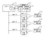
次に、図8を参照しながら本実施形態のスマートメータ検針システムの構成について詳細に説明する。図8は本実施形態のスマートメータ検針システムの構成を説明するためのブロック図である。また、図9は通信品質データを説明するための図である。 Next, the configuration of the smart meter meter reading system of this embodiment will be described in detail with reference to FIG. FIG. 8 is a block diagram for explaining the configuration of the smart meter meter reading system of this embodiment. FIG. 9 is a diagram for explaining communication quality data.
通信品質データ部201は、前記電力検針メータ無線子機A、B、C…N(Nは無線子機の数を示す自然数)とのFER値とRSSI値のデータを時間ごとに72時間分のデータ管理(記録)を行う(図9参照)。前記通信品質データ部201のデータを通信品質管理部203は、図3に示した電波信品質ランク判定例に示す品質ランクに伴い、前記電力検針メータ無線子機A、B、C…Nとの電波通信品質を管理する。 A communication
例えば、図9のN日の無線子機Aは図3の電波通信品質ランク判定例により、電波通信品質ランクAであったが、翌N+1日には、同電波通信品質ランク判定例により、電波通信品質ランクBに遷移した場合、集線装置102の通信品質管理部203が“無線子機故障予兆通知”を作成し、無線通信部105から有線接続部104を介して上位サーバに無線子機Aの無線子機の故障予兆である“無線子機故障予兆通知(ランクB)”を送信する。 For example, the wireless handset A on day N in FIG. When the communication quality rank is changed to B, the communication
また、図9の電波通信品質データ例に示すようにN+2日に無線子機Aの電波通信品質がさらに劣化したことにより電波通信品質ランクCに陥った場合、“無線子機故障予兆通知(ランクC)”を上位サーバに送信する。 Further, as shown in the example of radio communication quality data in FIG. C)” is sent to the upper server.
また、電力検針メータ無線子機Aが一時的に停電状態に陥った場合等、“無線子機故障通知”を上位サーバに送信してしまう場合が考えられるが、停電状況が一時的な事象であれば、無線子機との通信が復旧し、“無線部復旧通知”を送信することで、誤った故障通知を訂正できる。 In addition, when the power meter reading meter wireless cordless handset A temporarily falls into a power outage state, a "wireless cordless handset failure notification" may be sent to the host server, but the power outage is a temporary event. If so, the communication with the wireless slave unit is restored, and by transmitting the "radio section recovery notification", the erroneous failure notification can be corrected.
[効果の説明]
本実施形態のスマートメータ検針システムは、電力検針メータ無線子機の電波通信品質を電波通信品質ランクを付与して長期間監視することにより、故障予兆、故障発生との区別を設け、完全に無線部の故障に至る前に通知することができる。電力検針メータ無線子機からの通信が完全に途絶える(無線部故障)前に、無線子機の取替を促すことで、スマートメータ検針システムの検針値欠落を未然に防ぐ機能を実現できる。また、故障に至る変化の経過を統計的に把握できることで、計画的かつ効果的な機器の取替ができるようになる。[Explanation of effect]
The smart meter meter reading system of this embodiment assigns a radio communication quality rank to the radio communication quality of the wireless slave unit of the power meter and monitors it for a long period of time. It is possible to notify before the failure of the part. By urging replacement of the wireless slave unit before communication from the wireless slave unit of the power meter reading is completely cut off (failure of the wireless unit), it is possible to realize a function to prevent missing meter values in the smart meter meter reading system. In addition, by being able to statistically grasp the progress of changes that lead to failure, it becomes possible to systematically and effectively replace equipment.
上記の実施形態の一部又は全部は、以下のようにも記載され得るが、以下には限られな
い。
[形態1]
上述の第一の視点に係る遠隔測定装置のとおりである。
[形態2]
信号状態取得部は、前記信号状態として少なくとも信号強度と、信号の誤り率とを取得し、診断部は、信号強度と、誤り率とを用いて測定器の故障を診断する、好ましくは形態1の遠隔測定装置。
[形態3]
診断部は、信号強度と、誤り率とを用いて通信品質をランキングする、好ましくは形態2の遠隔測定装置。
[形態4]
ランキングに基づいて、測定器の故障を判定する故障判定部と、測定器が故障である旨の判定結果を通知する通知部と、を有する好ましくは形態3の遠隔測定装置。
[形態5]
故障判定部はさらに、故障との判定結果となった測定器の復旧を判定し、通知部は測定器が復旧した旨の判定結果を通知する、好ましくは形態4の遠隔測定装置。
[形態6]
ランキングに基づいて、測定器の故障を予測する故障予測部と、をさらに有し、通知部は故障が予測されている旨の予測結果を通知する、好ましくは形態4又は5の遠隔測定装置。
[形態7]
上述の第二の視点に係る遠隔測定システムのとおりである。
[形態8]
複数の測定器と、受信部は前記複数の測定器からの測定データを受信し、測定データをサーバ装置に送信する測定データ送信部と、をさらに有する遠隔測定装置と、測定データを受信する測定データ受信部と、受信した測定データを記憶域に格納する測定データ格納部と、を有するサーバ装置と、を含む好ましくは形態7の遠隔測定システム。
[形態9]
上述の第三の視点に係る遠隔測定方法のとおりである。
[形態10]
上述の第四の視点に係るプログラムのとおりである。
なお、形態9及び形態10は、形態1と同様に、形態2~形態6に展開することが可能である。Some or all of the above embodiments may also be described as follows, but are not limited to the following.
[Mode 1]
As the telemetry device according to the first aspect described above.
[Mode 2]
The signal state acquiring unit acquires at least the signal strength and the error rate of the signal as the signal state, and the diagnosis unit diagnoses a failure of the measuring device using the signal strength and the error rate, preferably form 1 telemetry device.
[Mode 3]
The telemetry device, preferably of
[Mode 4]
Preferably, the telemetry device of form 3, comprising a failure determination unit that determines failure of the measuring device based on the ranking, and a notification unit that notifies the determination result that the measuring device is defective.
[Mode 5]
Preferably, the telemetry device according to
[Mode 6]
a failure prediction unit for predicting failure of the meter based on the ranking, wherein the notification unit notifies the prediction result that failure is predicted.
[Mode 7]
As in the telemetry system according to the second aspect described above.
[Mode 8]
a telemetry device further comprising: a plurality of measuring devices; and a measurement data transmission unit, the receiving unit receiving measurement data from the plurality of measurement devices and transmitting the measurement data to a server device; 8. A telemetry system, preferably according to form 7, comprising a server device having a data receiver and a measurement data storage for storing the received measurement data in a storage area.
[Mode 9]
This is the telemetry method according to the third aspect described above.
[Form 10]
This is the same as the program related to the fourth viewpoint mentioned above.
It should be noted that the 9th and 10th forms can be developed into the 2nd to 6th forms in the same way as the 1st form.
なお、引用した上記の特許文献等の各開示は、本書に引用をもって繰り込むものとする。本発明の全開示(特許請求の範囲を含む)の枠内において、さらにその基本的技術思想に基づいて、実施形態ないし実施例の変更・調整が可能である。また、本発明の全開示の枠内において種々の開示要素(各請求項の各要素、各実施形態ないし実施例の各要素、各図面の各要素等を含む)の多様な組み合わせ、ないし、選択(部分的削除を含む)が可能である。すなわち、本発明は、特許請求の範囲を含む全開示、技術的思想にしたがって当業者であればなし得るであろう各種変形、修正を含むことは勿論である。特に、本書に記載した数値範囲については、当該範囲内に含まれる任意の数値ないし小範囲が、別段の記載のない場合でも具体的に記載されているものと解釈されるべきである。 The disclosures of the cited patent documents and the like are incorporated herein by reference. Within the framework of the full disclosure of the present invention (including the scope of claims), modifications and adjustments of the embodiments and examples are possible based on the basic technical concept thereof. Also, various combinations or selections of various disclosure elements (including each element of each claim, each element of each embodiment or example, each element of each drawing, etc.) within the framework of the full disclosure of the present invention (including partial deletion) is possible. That is, the present invention naturally includes various variations and modifications that can be made by those skilled in the art according to the entire disclosure including claims and technical ideas. In particular, any numerical range recited herein should be construed as specifically recited for any numerical value or subrange within that range, even if not otherwise stated.
10 遠隔測定装置
11 受信部
12 信号状態取得部
13 診断部
14 故障判定部
15 通知部
16 故障予測部
17 測定データ送信部
20、20-1~20-n 測定器
21 測定部
22 送信部
30 サーバ装置
31 測定データ受信部
32 測定データ格納部
51 CPU
52 メモリ
53 入出力インタフェース
54 無線通信モジュール
55 アンテナ
56 内部バス
101 上位サーバシステム
102 集線装置
103 OLT(Optical Line Terminal)
104 有線接続部(ONU:Optical Network Unit)
105 無線通信部
106、108、110 電力検針メータ
107、109、111 記憶装置
201、202 通信品質データ部
203、204 通信品質管理部10
52
104 wired connection unit (ONU: Optical Network Unit)
105
Claims (9)
Translated fromJapanese前記受信部にて前記測定データを受信した際の信号状態を取得する信号状態取得部と、
前記信号状態に基づいて前記測定器の故障を診断する診断部と、
を有し、
前記信号状態取得部は、前記信号状態として少なくとも信号強度と、信号の誤り率とを取得し、
前記診断部は、前記信号強度と、前記誤り率とを用いて前記測定器の故障を診断する、
遠隔測定装置。a receiver that receives measurement data from a measuring instrument;
a signal state acquisition unit that acquires a signal state when the measurement data is received by the reception unit;
a diagnostic unit that diagnoses a failure of the measuring device based on the signal state;
has
The signal state acquisition unit acquires at least a signal strength and a signal error rate as the signal state,
The diagnosis unit diagnoses a failure of the measuring device using the signal strength and the error rate.
Telemetry device.
前記測定器が故障である旨の判定結果を通知する通知部と、
を有する請求項2の遠隔測定装置。a failure determination unit that determines a failure of the measuring device based on the ranking;
a notification unit that notifies a determination result that the measuring device is out of order;
3. The telemetry device of claim2 , comprising:
前記通知部は前記測定器が復旧した旨の判定結果を通知する、
請求項3の遠隔測定装置。The failure determination unit further determines restoration of the measuring instrument determined as a failure,
The notification unit notifies the determination result that the measuring device has been restored,
4. The telemetry device of claim3 .
をさらに有し、
前記通知部は故障が予測されている旨の予測結果を通知する、
請求項3又は4の遠隔測定装置。a failure prediction unit that predicts a failure of the measuring device based on the ranking;
further having
The notification unit notifies a prediction result indicating that a failure is predicted;
5. A telemetry device according to claim3 or4 .
前記測定部で測定された測定データを送信する送信部と、
を有する測定器と、
前記測定器からの前記測定データを受信する受信部と、
前記受信部にて前記測定データを受信した際の信号状態を取得する信号状態取得部と、
前記信号状態に基づいて前記測定器の故障を診断する診断部と、
を有し、
前記信号状態取得部は、前記信号状態として少なくとも信号強度と、信号の誤り率とを取得し、
前記診断部は、前記信号強度と、前記誤り率とを用いて前記測定器の故障を診断する、
遠隔測定装置と、
を含む遠隔測定システム。a measuring unit that measures an object;
a transmission unit that transmits measurement data measured by the measurement unit;
a measuring instrument having
a receiving unit that receives the measurement data from the measuring device;
a signal state acquisition unit that acquires a signal state when the measurement data is received by the reception unit;
a diagnostic unit that diagnoses a failure of the measuring device based on the signal state;
has
The signal state acquisition unit acquires at least a signal strength and a signal error rate as the signal state,
The diagnosis unit diagnoses a failure of the measuring device using the signal strength and the error rate.
a telemetry device;
Telemetry system including.
前記受信部は前記複数の測定器からの前記測定データを受信し、
前記測定データを後記サーバ装置に送信する測定データ送信部と、
をさらに有する遠隔測定装置と、
前記測定データを受信する測定データ受信部と、
受信した前記測定データを記憶域に格納する測定データ格納部と、
を有するサーバ装置と、
を含む請求項6の遠隔測定システム。a plurality of said measuring instruments;
the receiving unit receives the measurement data from the plurality of measuring instruments;
a measurement data transmission unit that transmits the measurement data to a server device described later;
a telemetry device further comprising
a measurement data receiver that receives the measurement data;
a measurement data storage unit that stores the received measurement data in a storage area;
a server device having
7. The telemetry system of claim6 , comprising:
前記測定データを受信した際の信号状態として少なくとも信号強度と、信号の誤り率とを取得する信号状態取得ステップと、
前記信号強度と、前記誤り率とを用いて前記測定器の故障を診断する故障診断ステップと、
を有する遠隔測定方法。a receiving step of receiving measurement data from the measuring instrument;
a signal state acquiring stepof acquiring at least a signal strength and a signal error rate as the signal state when the measurement data is received;
a failure diagnosis step of diagnosing a failure of the measuring deviceusing the signal strength and the error rate ;
telemetry method.
前記測定データを受信した際の信号状態として少なくとも信号強度と、信号の誤り率とを取得する処理と、
前記信号強度と、前記誤り率とを用いて前記測定器の故障を診断する処理と、
をコンピュータで実行させるためのプログラム。a process of receiving measurement data from a measuring instrument;
A processof acquiring at least a signal strength and a signal error rate as a signal state when the measurement data is received;
A process of diagnosing a failure of the measuring deviceusing the signal strength and the error rate ;
A program that runs on a computer.
Priority Applications (1)
| Application Number | Priority Date | Filing Date | Title |
|---|---|---|---|
| JP2021210779AJP7287703B1 (en) | 2021-12-24 | 2021-12-24 | Telemetry device, telemetry system, telemetry method, and program |
Applications Claiming Priority (1)
| Application Number | Priority Date | Filing Date | Title |
|---|---|---|---|
| JP2021210779AJP7287703B1 (en) | 2021-12-24 | 2021-12-24 | Telemetry device, telemetry system, telemetry method, and program |
Publications (2)
| Publication Number | Publication Date |
|---|---|
| JP7287703B1true JP7287703B1 (en) | 2023-06-06 |
| JP2023095095A JP2023095095A (en) | 2023-07-06 |
Family
ID=86610994
Family Applications (1)
| Application Number | Title | Priority Date | Filing Date |
|---|---|---|---|
| JP2021210779AActiveJP7287703B1 (en) | 2021-12-24 | 2021-12-24 | Telemetry device, telemetry system, telemetry method, and program |
Country Status (1)
| Country | Link |
|---|---|
| JP (1) | JP7287703B1 (en) |
Citations (3)
| Publication number | Priority date | Publication date | Assignee | Title |
|---|---|---|---|---|
| JP2013075746A (en) | 2011-09-30 | 2013-04-25 | Seiko Epson Corp | Method and device for detecting double feed |
| JP2019108193A (en) | 2017-12-18 | 2019-07-04 | 京セラドキュメントソリューションズ株式会社 | Image forming apparatus, image forming method, and program |
| US20190342637A1 (en) | 2018-05-03 | 2019-11-07 | Dexcom, Inc. | Systems and methods for activating analyte sensor electronics |
Family Cites Families (1)
| Publication number | Priority date | Publication date | Assignee | Title |
|---|---|---|---|---|
| JPS58162245A (en)* | 1982-03-17 | 1983-09-26 | Ryoichi Saito | Preparation of bait for insect obtained by subjecting eristalis cerealis fabricius to antiseptic treatment |
- 2021
- 2021-12-24JPJP2021210779Apatent/JP7287703B1/enactiveActive
Patent Citations (3)
| Publication number | Priority date | Publication date | Assignee | Title |
|---|---|---|---|---|
| JP2013075746A (en) | 2011-09-30 | 2013-04-25 | Seiko Epson Corp | Method and device for detecting double feed |
| JP2019108193A (en) | 2017-12-18 | 2019-07-04 | 京セラドキュメントソリューションズ株式会社 | Image forming apparatus, image forming method, and program |
| US20190342637A1 (en) | 2018-05-03 | 2019-11-07 | Dexcom, Inc. | Systems and methods for activating analyte sensor electronics |
Also Published As
| Publication number | Publication date |
|---|---|
| JP2023095095A (en) | 2023-07-06 |
Similar Documents
| Publication | Publication Date | Title |
|---|---|---|
| US9686166B2 (en) | Power fluctuation detection and analysis | |
| KR102023465B1 (en) | Defect diagnosis system and the method of photovoltaic power generation equipment using Internet of Things | |
| US7860672B2 (en) | Method and apparatus for monitoring voltage in a meter network | |
| US20120310599A1 (en) | Sensor data collection system | |
| CN110618349B (en) | Ammeter line anomaly detection method, power terminal and power grid system | |
| JP2020123951A (en) | Method, apparatus and device for predicting failure of optical module | |
| US10636287B2 (en) | Automatic inspection system and automatic inspection method | |
| JP2009033811A (en) | Measuring / monitoring system, power quality measuring device, program | |
| US12373701B2 (en) | Method and apparatus for detecting and explaining anomalies | |
| US9398614B2 (en) | Data collection system, data collection device, wireless communication device, and communication method for collecting data | |
| WO2009091335A1 (en) | System for real time supervision of component wear in a wind turbine population | |
| JP7287703B1 (en) | Telemetry device, telemetry system, telemetry method, and program | |
| CN103278731B (en) | A kind of method for diagnosing faults based on secondary loop information and system | |
| KR20210026318A (en) | Server, method and computer program for synchronizing time between measuring device and electricity meter | |
| CN210181201U (en) | Data acquisition and transmission system for mutual inductor test assembly line verification | |
| CN114760182B (en) | Intelligent cable with temperature data acquisition function | |
| CN114337810B (en) | All-optical network communication system and communication method | |
| CN211149399U (en) | Server power supply enabling signal monitoring system | |
| KR101665312B1 (en) | remote meter reading system | |
| JP2023063981A (en) | Wireless sensor management device, wireless sensor management system and wireless sensor management method | |
| CN113915535A (en) | Urban gas pipeline network monitoring system and control method thereof | |
| KR101694348B1 (en) | Reading scheduling method in consideration of communication capability and time information of meters | |
| CN115378134B (en) | 5G-based power data processing system | |
| CN101949993A (en) | Indoor wireless network fault point diagnosing and positioning system | |
| JP7202998B2 (en) | Server device and error detection method |
Legal Events
| Date | Code | Title | Description |
|---|---|---|---|
| A621 | Written request for application examination | Free format text:JAPANESE INTERMEDIATE CODE: A621 Effective date:20211224 | |
| A131 | Notification of reasons for refusal | Free format text:JAPANESE INTERMEDIATE CODE: A131 Effective date:20221115 | |
| A521 | Request for written amendment filed | Free format text:JAPANESE INTERMEDIATE CODE: A523 Effective date:20230111 | |
| TRDD | Decision of grant or rejection written | ||
| A01 | Written decision to grant a patent or to grant a registration (utility model) | Free format text:JAPANESE INTERMEDIATE CODE: A01 Effective date:20230425 | |
| A61 | First payment of annual fees (during grant procedure) | Free format text:JAPANESE INTERMEDIATE CODE: A61 Effective date:20230518 | |
| R151 | Written notification of patent or utility model registration | Ref document number:7287703 Country of ref document:JP Free format text:JAPANESE INTERMEDIATE CODE: R151 |