JP7285847B2 - unmanned aerial vehicle - Google Patents
unmanned aerial vehicleDownload PDFInfo
- Publication number
- JP7285847B2 JP7285847B2JP2020539262AJP2020539262AJP7285847B2JP 7285847 B2JP7285847 B2JP 7285847B2JP 2020539262 AJP2020539262 AJP 2020539262AJP 2020539262 AJP2020539262 AJP 2020539262AJP 7285847 B2JP7285847 B2JP 7285847B2
- Authority
- JP
- Japan
- Prior art keywords
- battery
- arm
- backbone
- aerial vehicle
- unmanned aerial
- Prior art date
- Legal status (The legal status is an assumption and is not a legal conclusion. Google has not performed a legal analysis and makes no representation as to the accuracy of the status listed.)
- Active
Links
Images


Classifications
- B—PERFORMING OPERATIONS; TRANSPORTING
- B64—AIRCRAFT; AVIATION; COSMONAUTICS
- B64U—UNMANNED AERIAL VEHICLES [UAV]; EQUIPMENT THEREFOR
- B64U20/00—Constructional aspects of UAVs
- B64U20/50—Foldable or collapsible UAVs
- B—PERFORMING OPERATIONS; TRANSPORTING
- B64—AIRCRAFT; AVIATION; COSMONAUTICS
- B64C—AEROPLANES; HELICOPTERS
- B64C29/00—Aircraft capable of landing or taking-off vertically, e.g. vertical take-off and landing [VTOL] aircraft
- B64C29/0008—Aircraft capable of landing or taking-off vertically, e.g. vertical take-off and landing [VTOL] aircraft having its flight directional axis horizontal when grounded
- B64C29/0016—Aircraft capable of landing or taking-off vertically, e.g. vertical take-off and landing [VTOL] aircraft having its flight directional axis horizontal when grounded the lift during taking-off being created by free or ducted propellers or by blowers
- B64C29/0033—Aircraft capable of landing or taking-off vertically, e.g. vertical take-off and landing [VTOL] aircraft having its flight directional axis horizontal when grounded the lift during taking-off being created by free or ducted propellers or by blowers the propellers being tiltable relative to the fuselage
- B—PERFORMING OPERATIONS; TRANSPORTING
- B64—AIRCRAFT; AVIATION; COSMONAUTICS
- B64U—UNMANNED AERIAL VEHICLES [UAV]; EQUIPMENT THEREFOR
- B64U10/00—Type of UAV
- B64U10/10—Rotorcrafts
- B64U10/13—Flying platforms
- B64U10/14—Flying platforms with four distinct rotor axes, e.g. quadcopters
- B—PERFORMING OPERATIONS; TRANSPORTING
- B60—VEHICLES IN GENERAL
- B60L—PROPULSION OF ELECTRICALLY-PROPELLED VEHICLES; SUPPLYING ELECTRIC POWER FOR AUXILIARY EQUIPMENT OF ELECTRICALLY-PROPELLED VEHICLES; ELECTRODYNAMIC BRAKE SYSTEMS FOR VEHICLES IN GENERAL; MAGNETIC SUSPENSION OR LEVITATION FOR VEHICLES; MONITORING OPERATING VARIABLES OF ELECTRICALLY-PROPELLED VEHICLES; ELECTRIC SAFETY DEVICES FOR ELECTRICALLY-PROPELLED VEHICLES
- B60L50/00—Electric propulsion with power supplied within the vehicle
- B60L50/50—Electric propulsion with power supplied within the vehicle using propulsion power supplied by batteries or fuel cells
- B60L50/60—Electric propulsion with power supplied within the vehicle using propulsion power supplied by batteries or fuel cells using power supplied by batteries
- B60L50/64—Constructional details of batteries specially adapted for electric vehicles
- B—PERFORMING OPERATIONS; TRANSPORTING
- B60—VEHICLES IN GENERAL
- B60L—PROPULSION OF ELECTRICALLY-PROPELLED VEHICLES; SUPPLYING ELECTRIC POWER FOR AUXILIARY EQUIPMENT OF ELECTRICALLY-PROPELLED VEHICLES; ELECTRODYNAMIC BRAKE SYSTEMS FOR VEHICLES IN GENERAL; MAGNETIC SUSPENSION OR LEVITATION FOR VEHICLES; MONITORING OPERATING VARIABLES OF ELECTRICALLY-PROPELLED VEHICLES; ELECTRIC SAFETY DEVICES FOR ELECTRICALLY-PROPELLED VEHICLES
- B60L50/00—Electric propulsion with power supplied within the vehicle
- B60L50/50—Electric propulsion with power supplied within the vehicle using propulsion power supplied by batteries or fuel cells
- B60L50/60—Electric propulsion with power supplied within the vehicle using propulsion power supplied by batteries or fuel cells using power supplied by batteries
- B60L50/66—Arrangements of batteries
- B—PERFORMING OPERATIONS; TRANSPORTING
- B60—VEHICLES IN GENERAL
- B60L—PROPULSION OF ELECTRICALLY-PROPELLED VEHICLES; SUPPLYING ELECTRIC POWER FOR AUXILIARY EQUIPMENT OF ELECTRICALLY-PROPELLED VEHICLES; ELECTRODYNAMIC BRAKE SYSTEMS FOR VEHICLES IN GENERAL; MAGNETIC SUSPENSION OR LEVITATION FOR VEHICLES; MONITORING OPERATING VARIABLES OF ELECTRICALLY-PROPELLED VEHICLES; ELECTRIC SAFETY DEVICES FOR ELECTRICALLY-PROPELLED VEHICLES
- B60L58/00—Methods or circuit arrangements for monitoring or controlling batteries or fuel cells, specially adapted for electric vehicles
- B60L58/10—Methods or circuit arrangements for monitoring or controlling batteries or fuel cells, specially adapted for electric vehicles for monitoring or controlling batteries
- B—PERFORMING OPERATIONS; TRANSPORTING
- B64—AIRCRAFT; AVIATION; COSMONAUTICS
- B64D—EQUIPMENT FOR FITTING IN OR TO AIRCRAFT; FLIGHT SUITS; PARACHUTES; ARRANGEMENT OR MOUNTING OF POWER PLANTS OR PROPULSION TRANSMISSIONS IN AIRCRAFT
- B64D27/00—Arrangement or mounting of power plants in aircraft; Aircraft characterised by the type or position of power plants
- B64D27/40—Arrangements for mounting power plants in aircraft
- B64D27/402—Arrangements for mounting power plants in aircraft comprising box like supporting frames, e.g. pylons or arrangements for embracing the power plant
- B—PERFORMING OPERATIONS; TRANSPORTING
- B64—AIRCRAFT; AVIATION; COSMONAUTICS
- B64U—UNMANNED AERIAL VEHICLES [UAV]; EQUIPMENT THEREFOR
- B64U20/00—Constructional aspects of UAVs
- B64U20/80—Arrangement of on-board electronics, e.g. avionics systems or wiring
- B64U20/87—Mounting of imaging devices, e.g. mounting of gimbals
- B—PERFORMING OPERATIONS; TRANSPORTING
- B64—AIRCRAFT; AVIATION; COSMONAUTICS
- B64U—UNMANNED AERIAL VEHICLES [UAV]; EQUIPMENT THEREFOR
- B64U30/00—Means for producing lift; Empennages; Arrangements thereof
- B64U30/20—Rotors; Rotor supports
- B64U30/29—Constructional aspects of rotors or rotor supports; Arrangements thereof
- B64U30/293—Foldable or collapsible rotors or rotor supports
- B—PERFORMING OPERATIONS; TRANSPORTING
- B64—AIRCRAFT; AVIATION; COSMONAUTICS
- B64U—UNMANNED AERIAL VEHICLES [UAV]; EQUIPMENT THEREFOR
- B64U50/00—Propulsion; Power supply
- B64U50/10—Propulsion
- B64U50/13—Propulsion using external fans or propellers
- B—PERFORMING OPERATIONS; TRANSPORTING
- B64—AIRCRAFT; AVIATION; COSMONAUTICS
- B64U—UNMANNED AERIAL VEHICLES [UAV]; EQUIPMENT THEREFOR
- B64U50/00—Propulsion; Power supply
- B64U50/10—Propulsion
- B64U50/19—Propulsion using electrically powered motors
- H—ELECTRICITY
- H01—ELECTRIC ELEMENTS
- H01M—PROCESSES OR MEANS, e.g. BATTERIES, FOR THE DIRECT CONVERSION OF CHEMICAL ENERGY INTO ELECTRICAL ENERGY
- H01M50/00—Constructional details or processes of manufacture of the non-active parts of electrochemical cells other than fuel cells, e.g. hybrid cells
- H01M50/20—Mountings; Secondary casings or frames; Racks, modules or packs; Suspension devices; Shock absorbers; Transport or carrying devices; Holders
- B—PERFORMING OPERATIONS; TRANSPORTING
- B60—VEHICLES IN GENERAL
- B60L—PROPULSION OF ELECTRICALLY-PROPELLED VEHICLES; SUPPLYING ELECTRIC POWER FOR AUXILIARY EQUIPMENT OF ELECTRICALLY-PROPELLED VEHICLES; ELECTRODYNAMIC BRAKE SYSTEMS FOR VEHICLES IN GENERAL; MAGNETIC SUSPENSION OR LEVITATION FOR VEHICLES; MONITORING OPERATING VARIABLES OF ELECTRICALLY-PROPELLED VEHICLES; ELECTRIC SAFETY DEVICES FOR ELECTRICALLY-PROPELLED VEHICLES
- B60L2200/00—Type of vehicles
- B60L2200/10—Air crafts
- B—PERFORMING OPERATIONS; TRANSPORTING
- B64—AIRCRAFT; AVIATION; COSMONAUTICS
- B64U—UNMANNED AERIAL VEHICLES [UAV]; EQUIPMENT THEREFOR
- B64U30/00—Means for producing lift; Empennages; Arrangements thereof
- B64U30/20—Rotors; Rotor supports
- B64U30/29—Constructional aspects of rotors or rotor supports; Arrangements thereof
- B—PERFORMING OPERATIONS; TRANSPORTING
- B64—AIRCRAFT; AVIATION; COSMONAUTICS
- B64U—UNMANNED AERIAL VEHICLES [UAV]; EQUIPMENT THEREFOR
- B64U60/00—Undercarriages
- B64U60/50—Undercarriages with landing legs
- H—ELECTRICITY
- H01—ELECTRIC ELEMENTS
- H01M—PROCESSES OR MEANS, e.g. BATTERIES, FOR THE DIRECT CONVERSION OF CHEMICAL ENERGY INTO ELECTRICAL ENERGY
- H01M2220/00—Batteries for particular applications
- H01M2220/20—Batteries in motive systems, e.g. vehicle, ship, plane
- Y—GENERAL TAGGING OF NEW TECHNOLOGICAL DEVELOPMENTS; GENERAL TAGGING OF CROSS-SECTIONAL TECHNOLOGIES SPANNING OVER SEVERAL SECTIONS OF THE IPC; TECHNICAL SUBJECTS COVERED BY FORMER USPC CROSS-REFERENCE ART COLLECTIONS [XRACs] AND DIGESTS
- Y02—TECHNOLOGIES OR APPLICATIONS FOR MITIGATION OR ADAPTATION AGAINST CLIMATE CHANGE
- Y02E—REDUCTION OF GREENHOUSE GAS [GHG] EMISSIONS, RELATED TO ENERGY GENERATION, TRANSMISSION OR DISTRIBUTION
- Y02E60/00—Enabling technologies; Technologies with a potential or indirect contribution to GHG emissions mitigation
- Y02E60/10—Energy storage using batteries
- Y—GENERAL TAGGING OF NEW TECHNOLOGICAL DEVELOPMENTS; GENERAL TAGGING OF CROSS-SECTIONAL TECHNOLOGIES SPANNING OVER SEVERAL SECTIONS OF THE IPC; TECHNICAL SUBJECTS COVERED BY FORMER USPC CROSS-REFERENCE ART COLLECTIONS [XRACs] AND DIGESTS
- Y02—TECHNOLOGIES OR APPLICATIONS FOR MITIGATION OR ADAPTATION AGAINST CLIMATE CHANGE
- Y02T—CLIMATE CHANGE MITIGATION TECHNOLOGIES RELATED TO TRANSPORTATION
- Y02T10/00—Road transport of goods or passengers
- Y02T10/60—Other road transportation technologies with climate change mitigation effect
- Y02T10/70—Energy storage systems for electromobility, e.g. batteries
- Y—GENERAL TAGGING OF NEW TECHNOLOGICAL DEVELOPMENTS; GENERAL TAGGING OF CROSS-SECTIONAL TECHNOLOGIES SPANNING OVER SEVERAL SECTIONS OF THE IPC; TECHNICAL SUBJECTS COVERED BY FORMER USPC CROSS-REFERENCE ART COLLECTIONS [XRACs] AND DIGESTS
- Y02—TECHNOLOGIES OR APPLICATIONS FOR MITIGATION OR ADAPTATION AGAINST CLIMATE CHANGE
- Y02T—CLIMATE CHANGE MITIGATION TECHNOLOGIES RELATED TO TRANSPORTATION
- Y02T50/00—Aeronautics or air transport
- Y02T50/60—Efficient propulsion technologies, e.g. for aircraft
Landscapes
- Engineering & Computer Science (AREA)
- Mechanical Engineering (AREA)
- Aviation & Aerospace Engineering (AREA)
- Remote Sensing (AREA)
- Chemical & Material Sciences (AREA)
- Combustion & Propulsion (AREA)
- Life Sciences & Earth Sciences (AREA)
- Sustainable Development (AREA)
- Sustainable Energy (AREA)
- Power Engineering (AREA)
- Transportation (AREA)
- Electrochemistry (AREA)
- Chemical Kinetics & Catalysis (AREA)
- General Chemical & Material Sciences (AREA)
- Microelectronics & Electronic Packaging (AREA)
- Battery Mounting, Suspending (AREA)
- Air Bags (AREA)
- Forklifts And Lifting Vehicles (AREA)
Description
Translated fromJapanese本発明は、添付の特許請求の範囲の前段に特定されたような、無人航空機(UAV)に関する。 The present invention relates to an unmanned aerial vehicle (UAV) as specified in the preamble of the appended claims.
無人の、遠隔操作型または自立型の航空機は、近年において非常に人気を得ている。そのような航空機は一般的にドローンと称され、法執行機関および救助機関の専門家により、航空写真、調査、および貨物の搬送等に現在では広範囲に使用されている。したがって、比較的重い貨物を運搬することが可能であり、小型の状態で現場に搬送され得、且つ迅速に展開および飛行の準備ができるドローンが、必要とされている。 Unmanned, remotely operated or autonomous aircraft have become very popular in recent years. Such aircraft, commonly referred to as drones, are now extensively used by law enforcement and rescue professionals for aerial photography, surveys, cargo transport, and the like. What is needed, therefore, is a drone that can carry relatively heavy cargo, can be transported to a site in a compact form, and can be deployed and ready for flight quickly.
先行技術は、貨物コンテナ、陸上車両、船舶、医療用輸送モジュール等に連結可能な航空機を備えたモジュール型手段を記載した特許文献1を含んでいる。一実施形態において、航空機は、主機体フレームの周りに配置された複数のプロペラを備え、これらのプロペラは、垂直推進力および/または水平推進力を提供することが可能である。1つ以上のプロペラは、機体フレームに対して前傾し、後傾し、および左右に傾斜するように構成され得る。 The prior art includes US Pat. No. 6,000,003 which describes a modular means with an aircraft connectable to cargo containers, land vehicles, ships, medical transport modules and the like. In one embodiment, an aircraft comprises a plurality of propellers arranged around a main fuselage frame, which propellers are capable of providing vertical and/or horizontal propulsion. The one or more propellers may be configured to tilt forward, backward, and tilt side to side with respect to the airframe.
先行技術は、使用していない場合に自身の体積を減少させることが可能なドローンを記載した特許文献2も含んでいる。ドローンの機体フレームは長方形であり、ドローンの(ロータが搭載された)アームは、機体フレームに沿って折り畳まれるように旋回可能である。機体フレームの前部の幅は、後部の幅よりも大きく、それにより前後のアームは、横に並んで、互いに重なることなく折り畳まれることが可能である。
先行技術は特許文献3も含んでおり、特許文献3は、無人航空機本体およびバッテリカバーを備えた、バッテリ自己離脱無人航空機のためのバッテリ固定および装着構造を記載している。バッテリを収容するために使用されるバッテリ室は、無人航空機本体の底部に形成されている。ヒンジ接続穴が、バッテリ室の一側に形成されている。ヒンジ接続穴と合致するヒンジ接続ピラーは、バッテリカバーの対応した一側に配置されている。ヒンジ接続ピラーは、ヒンジ接続穴内に接続され、バッテリカバーを無人航空機本体上にヒンジ接続することを可能にしている。The prior art also includes US Pat. No. 6,300,000, which describes a drone capable of reducing its volume when not in use. The drone's fuselage frame is rectangular, and the drone's arm (on which the rotor is mounted) is pivotable to fold along the fuselage frame. The width of the front part of the fuselage frame is greater than the width of the rear part, so that the front and rear arms can be folded side by side without overlapping each other.
The prior art also includes US Pat. No. 6,200,302, which describes a battery fixing and mounting structure for a battery self-disengaging unmanned aerial vehicle, comprising an unmanned aerial vehicle body and a battery cover. A battery compartment used to house the battery is formed in the bottom of the unmanned aerial vehicle body. A hinge connection hole is formed in one side of the battery compartment. A hinge connection pillar that mates with the hinge connection hole is disposed on a corresponding side of the battery cover. A hinge connection pillar is connected within the hinge connection hole to allow the battery cover to be hinged onto the unmanned aerial vehicle body.
本発明の目的は、信頼性が高く、長期間安定したロータ翼マルチコプター型の、および複数のモータを備え高速展開可能な航空機を提供することであり、それらはドローンとして有利に操作可能であり、機体に固定されたまたはスリングでドローンに接続された重い貨物を運搬するように設計されている。貨物は約5kgから約500kgの範囲とし得る。 SUMMARY OF THE INVENTION It is an object of the present invention to provide reliable, long-term stable rotor-wing multicopter-type and multiple-motor, rapidly deployable aircraft that can be advantageously operated as drones. , designed to carry heavy cargo that is fixed to the fuselage or attached to the drone with a sling. Cargo may range from about 5 kg to about 500 kg.
発明者は、単一の主機体を備えて、およびここに図示され且つ記載されたような、有利に揺動可能なアームマウントを備えて実施された、急速展開可能な無人マルチコプターのような、ロータ翼揚力発生手段を備えた急速展開可能な航空機、有利に急速展開可能な無人航空機(UAV)が、用途における使用に関して非常に望ましいものとされる有利な特性および能力を示すことを見出した。その用途では、有人飛行機または有人ヘリコプターのような有人航空機が、人員にもしくは装備に対して高い危険性もしくは高コストを含んでいるか、または特に、不利な運転条件下での緊急事態においてその使用を禁止するような、その運転においてその他の実質的な制限を満たしている。本発明の装置は、特に急速展開を提供すること、および実質的に経時変化しないままである安定性を有し、ほんの数分で動作の準備を完了すること、を可能にしている。The inventors have sought to develop a rapid deployable unmanned multicopter, such as a rapidly deployable unmanned multicopter, embodied with a single main vehicle and advantageously with swingable arm mounts as shown and described herein. , found that a rapidly deployable aircraft, advantageously a rapidly deployable unmanned aerial vehicle (UAV ), with rotor wing lift generating means, exhibits advantageous properties and capabilities that make it highly desirable for use in applications. . The applications involve manned aircraft, such as manned airplanes or manned helicopters, which involve high risk or high cost to personnel or equipment, or preclude their use in emergency situations, especially under adverse operating conditions. Meets other material restrictions on its operation that are prohibited. The device of the present invention makes it possible to provide particularly rapid deployment and to be ready for operation in a matter of minutes, having a stability that remains virtually unchanged over time.
本発明は、主請求項において説明され且つ特徴付けられており、一方で従属請求項は、本発明の他の特徴を記載している。 The invention is set forth and characterized in the main claim, while the dependent claims describe other features of the invention.
したがって、前方エンドピースおよび後方エンドピースを備えた少なくとも1つのバックボーンと称される細長い主フレームを備えた主本体を有する無人航空機が提供されており、エンドピースはバックボーンよりも幅広であり、且つ個々のロータアームのための連結機器を備え、各々のロータアームは、モータおよびプロペラアセンブリを支持するように構成されており、無人航空機は、一対の細長いバッテリをさらに備え、バックボーンの両側に個々に電気バッテリを解放可能に受容するための収納部を形成しており、バッテリ、バックボーン、およびエンドピースは、細長く略長方形の本体アセンブリを形成している。Accordingly, there is provided an unmanned aerial vehicle having a main body withan elongated main frame, called backbone , with at least one forward end piece and an aft end piece, the end pieces being wider than the backbone and individually each rotor arm configured to support a motor and propeller assembly; Forming a receptacle for releasably receiving a battery, the battery, backbone, and end pieces form an elongated, generally rectangular body assembly.
一実施形態においては、各ロータアームは、エンドピースに連結するように形成された連結手段を一方の端部に、およびアーム折り畳みヒンジの第1部分を第2の端部に備えたアーム内側部分と、モータおよびプロペラアセンブリのためのアダプタを一方の端部に、およびアーム折り畳みヒンジの第2部分を第2の端部に備えたアーム外側部分と、アーム内側部分およびアーム外側部分の最初の一方に配置された、変位可能なバネ付勢されたヒンジロック手段と、を備えている。折り畳まれていない位置に位置決めされた場合に、アームは、アーム外側部分の穴に入るように形成された、バネ付勢されたコッタピンをさらに備えている。In one embodiment each rotor arm comprises an arm inner portion provided at one end with connecting means formed to connect to the end piece and at a second end a first portion of an arm folding hinge. and an arm outer portion with an adapter for the motor and propeller assembly at one end and a second portion of the arm folding hinge at the second end, and a first one of the arm inner portion and the arm outer portion. a displaceable, spring-loaded hinge locking means disposed in the . The arm further includes a spring-biased cotter pin configuredto enter a hole in the arm outer portion when positioned in the unfolded position.
本発明は、揚力発生手段を備えた航空機のための、揺動可能なアームマウントを提供しており、航空機は有利にマルチコプターである。 The present invention provides a swingable arm mount for an aircraft with lift generating means, the aircraft being advantageously a multicopter.
したがって、本発明は主本体を備えた無人マルチコプターを提供することが可能であることを意図されており、この主本体は、
第1端部および第2端部を備えた、軽金属の押出プロファイルの単一部品から形成された細長いバックボーン(中央本体/機体)であって、その内部の4つの細長いキャビティ、および少なくとも1つの外側「バックボーン」長辺、ならびにカメラ脚およびそれに類似した機器を取り付けるための例えば装着トラック等の他の外形特性を備えた、バックボーンと、
「バックボーン」の第1端部に装着するための前方エンドピースであって、「バックボーン」に装着される部分の幅がバックボーンよりも広い幅を有し、少なくとも第1前方ショルダおよび第2前方ショルダを提供し、各ショルダはロータアームのための連結機器を備え、追加的にアンダーキャリッジ(少なくとも1つの脚)のための前方装着機器も備えた、前方エンドピースと、
「バックボーン」の第2端部に装着するための後方エンドピースであって、「バックボーン」に装着される部分の幅がバックボーンよりも広い幅を有し、少なくとも第1後方ショルダおよび第2後方ショルダを提供し、各ショルダはロータアームのための連結機器を備え、追加的にアンダーキャリッジ(少なくとも1つの脚)のための後方装着機器も備えた、後方エンドピースと、
機首エンドキャップおよびステムエンドキャップと、
前方装着機器を提供するための追加の前方アダプタプレート、および前方エンドピースと機首エンドキャップとの間のアダプタと、
後方装着機器を提供するための追加の後方アダプタプレート、および後方エンドピースとステムエンドキャップとの間のアダプタと、
4つの折り畳み可能なロータアームであって、各ロータアームは、エンドピースの連結機器に連結するように形成された連結手段を一方の端部に、およびアーム折り畳みヒンジの第1部分を第2の端部に備えたアーム内側部分と、ロータアセンブリのためのアダプタを一方の端部に、およびアーム折り畳みヒンジの第2部分を第2の端部に備えたアーム外側部分と、アーム内側部分およびアーム外側部分の最初の一方に配置され、折り畳まれていない位置に位置決めされた場合に、前記アーム内側部分および前記アーム外側部分の他方の穴にはいるように形成された、バネ付勢されたコッタピンを備えた、変位可能なバネ付勢されたヒンジロック手段と、を備え、4つのロータアセンブリの各々が、ロータアセンブリのための個々の1つのアダプタに取り付けられたロータマウント上のモータの、少なくとも1つのプロペラを備えた、折り畳み可能なアームと、を備えている。Accordingly, the present invention is intended to be able to provide an unmanned multicopter with a main body, which main body comprises:
An elongated backbone (central body/fuselage) formed from a single piece of light metal extruded profile with a first end and a second end, having four elongated cavities therein and at least one outer side. a backbone with a "backbone" long side and other features such as mounting tracks for mounting camera legs and similar equipment;
A front endpiece for attachment to a first end of the "backbone", the portion attached to the "backbone" having a greater width than the backbone and at least a first front shoulder and a second front shoulder. a front end piece, each shoulder comprising coupling equipment for the rotor arms and additionally also comprising front mounting equipment for the undercarriage (at least one leg);
A rear endpiece for attachment to a second end of the "backbone", the portion attached to the "backbone" having a greater width than the backbone, and at least a first rear shoulder and a second rear shoulder. a rear end piece, each shoulder comprising coupling equipment for the rotor arms and additionally also comprising rear mounting equipment for the undercarriage (at least one leg);
a nose end cap and a stem end cap;
an additional forward adapter plate to provide forward mounted equipment and an adapter between the forward endpiece and the nose endcap;
an additional posterior adapter plate to provide posteriorly mounted equipment and an adapter between the posterior endpiece and the stem end cap;
Four foldable rotor arms, each rotor arm having at one end connection means formed to connect to the connection device of the end piece and at the second end a first portion of the arm folding hinge. an arm inner part with an end, an arm outer part with an adapter for the rotor assembly at one end and a second part of the arm folding hinge at a second end, an arm inner part and the arm A spring-biased cotter pin disposed in the first one of the outer portions and configured to enter the holes in the other of the inner arm portion and the outer arm portion when positioned in the unfolded position. a displaceable spring-loaded hinge locking means comprising at least a foldable arm with one propeller.
好適に、本発明は無人マルチコプターを提供することが可能であり、このマルチコプターは、少なくとも1つの細長いエネルギ容器、好適に電気バッテリを備え、バッテリは、第1端部、第2端部、および「バックボーン」の少なくとも1つの長辺に隣接して配置されるように形成された外側バッテリ長辺を備え、第1端部および第2端部の少なくとも一方に取付手段を備え、この取付手段は、前方エンドピースおよび後方エンドピースの少なくとも一方に配置された、少なくとも1つの協働する取付手段と固定的係合状態となるように形成されている。 Advantageously, the present invention is capable of providing an unmanned multicopter comprising at least one elongated energy container, preferably an electric battery, the battery comprising a first end, a second end and a second end. and an outer battery long side configured to be positioned adjacent at least one long side of the "backbone", and mounting means at at least one of the first and second ends, the mounting means are configured to be in fixed engagement with at least one cooperating attachment means located on at least one of the front and rear endpieces.
本発明の前述のおよび他の特徴は、添付された概略的な図を参照するとともに、非限定的な例として提供された実施形態の優先的形式の以下の記載から明確になるだろう。 The foregoing and other features of the invention will become clear from the following description of preferred forms of embodiments given as non-limiting examples, with reference to the attached schematic drawings.
以下の記載は、「水平な」、「垂直な」、「横方向」、「後および前」、「上および下」、「上側」、「下側」、「内側」、「外側」、「前方」、「後方」等の用語を使用し得る。これらの用語は、全体的に図に示されたような視点および配向を参照しており、それらは本発明の通常の使用に関連している。これらの用語は、読者の利便のみのために使用され、限定されない。 The following descriptions are "horizontal", "vertical", "lateral", "back and front", "top and bottom", "upper", "lower", "inner", "outer", " Terms such as "forward", "rearward" may be used. These terms generally refer to the perspectives and orientations as shown in the figures with which they relate to the normal use of the invention. These terms are used for the reader's convenience only and are not limiting.
以下の記載における簡素化のために、完成したなロータアーム、ならびにモータマウント、モータ、およびプロペラを備えたロータアセンブリ、を備えたアセンブリは、高頻度で「アーム」と称される。バッテリ、アーム、およびアンダーキャリッジを除いて、(一般に「バックボーン」と称される)主フレーム、エンドピース、エンドキャップ、およびそれらに装着された部品を備えたドローン本体は、高頻度で「本体」と称される。 For simplicity in the following description, the assembly comprising the complete rotor arm and the rotor assembly comprising the motor mount, motor and propeller is frequently referred to as the "arm". The drone body, with the main frame (commonly referred to as the "backbone"), end pieces, end caps, and the parts attached to them, excluding the battery, arms, and undercarriage, is frequently referred to as the "main body". is called
最初に図1から図4を参照すると、展開されて本体100から広がったアーム200を備えた構成における、本発明の実施形態による完成したロータ翼マルチコプターが示されており、これは、完全に展開された状態でロックされ、飛行の準備ができている。図1は、主アセンブリ、および自身に装着された一対のバッテリ500を備えた本体100のような部品を示しており、これらは細長く且つ略長方形の本体アセンブリを形成している。ロータアセンブリ400、および複数の脚600を含んだアンダーキャリッジを備えた複数のロータアーム200は、本体100に装着されている。 Referring initially to FIGS. 1-4, there is shown a completed rotor blade multicopter according to an embodiment of the present invention in a configuration with
図2は、センサ窓111を備えた前方エンドキャップ110、追加の前方アダプタプレート120、前方エンドピース130、バックボーン140、後方エンドピース150、追加の後方アダプタプレート160、ステムエンドキャップ170、およびバッテリ係止手段190等の、本体100の部品およびサブアセンブリ、アーム内側部分210、アーム外側部分220、およびアーム折り畳みヒンジ係止手段230等の、アーム200の部品およびサブアセンブリ、ならびにロータマウント410、上側モータおよびプロペラアセンブリ420A、および下側モータおよびプロペラアセンブリ420B等の、ロータアセンブリ400の部品およびサブアセンブリ、を示している。 FIG. 2 shows a
図3および図4は、本体バックボーン140、ならびに前方ショルダ131および132を示しており、これらのショルダは、前方アーム200の本体100への固定的な取り付けに寄与するために配置された、前方エンドピース130に配置されたアダプタを備えている。対応して、後方エンドピース150は後方ショルダ151および152を含んでおり、これらのショルダは、後方アーム200の本体100への固定的な取り付けに寄与するために配置された、後方エンドピース150に配置されたアダプタを備えている。 FIGS. 3 and 4
電気的接続のためのバッテリコネクタ180は、バックボーン140の少なくとも一方の側部に設けられ、バッテリの嵌合電気コネクタ580との接続に寄与するように形成されている。バッテリ保持および係止手段第1部品190は、前方エンドピース130および後方エンドピース150のそれぞれの側部に配置されており、これらの部品は本体100の長手軸に略直交し且つ互いに向き合っている。バッテリ保持および係止手段第2部品514は、バッテリ保持および係止手段第1部品190と協働して係合するように設計されており、各バッテリ500のそれぞれの端部に配置されている。図3および図4を参照すると、バッテリ保持および係止手段190は、係止解除且つバッテリを解放した位置で示されており、前方エンドピース130および後方エンドピース150の側部の下縁から突出したL字形状要素が見えており、これらの要素は互いに向き合っており、バッテリ500が本体のこれらの側部の間に装着されていない場合に、これらの要素が見えることが理解されるべきである。
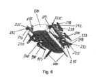
図5から図8を参照すると、アーム200が本体100に対して折り畳まれ且つ折り畳まれた状態で係止されて、格納または搬送の準備が完了した構成において、本発明によるロータ翼マルチコプターが示されている。図5から図8は、アーム折り畳みヒンジ係止手段230の係止スライダ231および係止ピン232、アーム内側部分210の端部218、ならびにアーム外側部分220の端部225を特定しており、両方の端部は円錐曲線回転面のセクションに対応した形状である。アーム内側部分210の端部215およびアーム外側部分220の端部228は、中空の円錐曲線回転面のセクションであり、端部225および218に合致する形状であり、アームが折り畳まれた状態から展開された状態へと折り畳みヒンジの周りに回転された場合に、それぞれが端部225および218のそれぞれを受容する。それにより、折り畳み位置と展開位置との間を移動する場合に、アームの長手軸の周りにおよび長手軸を横切って作用するトルクおよび剪断力等の力は、内側部分210と外側部分220との間に直接伝達され、ヒンジピンに応力を加えることなく、アーム外側部分がヒンジピンの周りを回転する。 5-8, a rotor blade multicopter according to the present invention is shown in a configuration in which the
図8は、単一バックボーン140内の装着トラック145を特定しており、このトラック内に、例えばカメラ脚等の補助装備が装着され得る。図1および図2と同様に図5から図8において、バッテリ保持および係止手段190のレバーは、本体の所定の位置にバッテリを係止および保持するための位置にあり、前方エンドピース130および後方エンドピース150の下縁から突出した、図3および図4に示されたL字形状レバー要素は、図1および図2と同様に図5および図6においては、バッテリ500が完全に本体に装着された場合に、前方エンドピース130および後方エンドピース150の凹部内に配置され、これらの凹部とそれぞれの隣接した側端部514との間にほぼ隠れていることが理解されるべきである。 FIG. 8 identifies a mounting track 145 within the
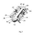
ここで図9および図10を参照すると、本発明による航空機のマルチコプターの実施形態の主要素およびサブアセンブリが図示され、且つ特定されている。図9は、機首エンドキャップ110、追加の前方アダプタプレート120、前方エンドピース130、バッテリに接続するための電気コネクタ180を備えた本体バックボーン140、バッテリ保持および係止手段190の部品を備えた後方エンドピース150、追加の後方アダプタプレート160、ステムエンドキャップ170等の、本体100の要素およびサブアセンブリ、アーム内側部分210、アーム折り畳みヒンジ手段230、およびアーム外側部分220等の、ロータアーム200の要素およびサブアセンブリ、ならびにモータマウント410、上側ロータアセンブリ420A、および下側ロータアセンブリ420B等の、ロータ400の要素およびサブアセンブリ、を示している。図10は、アーム内側部分210の端部218、およびアーム外側部分220の端部225を図示および特定しており、両方の端部は、円錐曲線回転面の一部のセクションに対応した形状である。アーム内側部分210の端部215およびアーム外側部分220の端部228は、中空の同様の円錐曲線回転面のセクションであり、端部225および218と相補的に合致した形状であり、これによりアームが折り畳まれた状態から展開された状態へと折り畳みヒンジの周りに回転した場合に、それぞれが端部225および218のそれぞれを受容することが可能である。 9 and 10, the main elements and subassemblies of an aircraft multicopter embodiment according to the present invention are illustrated and identified. FIG. 9 includes parts of
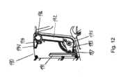
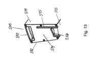
ここで図11および図12を参照すると、本発明の航空機の実施形態による、マルチコプターの前方エンドピース130および後方エンドピース150の側部に配置されるバッテリ係止手段190の要素およびサブアセンブリが図示および特定されており、図13を参照すると、細長いバッテリ500の端部の短辺514に配置されたバッテリ保持および係止手段の要素およびサブアセンブリが図示および特定されている。 11 and 12, elements and subassemblies of a battery locking means 190 located on the sides of the
図11および図12は、レール191、指把持開口部196、レバー回転軸および軸受195、キャリアスタッド193、およびレバーラッチカム194を備えたレバー192、ならびにレバーラッチピンおよび解除ボタン198を図示および特定している。便宜上、次の図13を参照すると、バッテリ500の上部長辺510、内側長辺511、外側長辺512、底部長辺513、および端部短辺514を含んだバッテリ500の特徴を図示および特定しており、このバッテリは端部短辺514において、直線の第1収納トラック515およびL字形状の第2収納トラック516を含んだバッテリ保持および係止手段を備え、両方のトラックは、底部長辺513の端縁に端部開口部を備えている。直線の第1収納トラック515はその開口部にレール191を受容して、バッテリ500を本体100上でスライドさせるように制御する寸法とされ、且つバッテリの端部短辺514上に配置されており、これによりバッテリをバックボーン140の長辺に隣接するように配置し、且つバッテリの電気コネクタ580を本体100の電気コネクタ180と位置合わせするように配置している。 11 and 12 illustrate and identify rail 191, finger grip opening 196, lever pivot and bearing 195, carrier stud 193,
L字形状の第2収納トラック516の開口部は、バッテリの端部短辺514に配置されており、これにより図11に示された係止解除および解放位置に位置したレバー192のキャリアスタッド193を受容することを可能にしている。L字形状の第2収納トラック516の角部は、電気コネクタ580が電気コネクタ180と接触しようとする位置まで、バッテリがレール191に沿って滑った場合に、キャリアスタッド193と接触するように配置されており、この位置において、キャリアスタッド193は、レバーがその回転軸および軸受195の周りに回転されるまで、バッテリのさらなる移動を停止させる。そのとき、バッテリ係止位置へと向かうレバーの回転は円軌跡に従い、且つL字形状の第2収納トラック516の水平部分により制限され、キャリアスタッド193はバッテリ500を移動させて、てこの作用によりバッテリをさらに所定の位置へと移動させ、この位置において、バッテリの上部長辺510および底部長辺513がバックボーン140の上部長辺および底部長辺のそれぞれと略同一平面上となり、且つバッテリの電気コネクタ580は本体の電気コネクタと完全に嵌合して接続される。 The opening of the L-shaped secondary storage track 516 is located on the battery end short side 514 thereby allowing the carrier stud 193 of the
逆に、保持および係止された位置にある、本体100にすでに搭載されたバッテリ500に関して、レバーの係止解除および解放位置に向かった回転により、キャリアスタッド193が反対方向の円軌跡に従い、且つL字形状の第2収納トラック516の水平部分により制限されて、キャリアスタッド193はバッテリ500を移動させて、てこの作用によりバッテリをさらに所定の位置へと移動させ、この位置において、バッテリの上部長辺510および底部長辺513は、バックボーン140の上部長辺および底部長辺のそれぞれに対して持ち上げられ、バッテリの電気コネクタ580は本体の電気コネクタ180から完全に持ち上げられて離脱される。バッテリ500を保持および係止するための位置に入る際に、レバーラッチカム194はレバーラッチピンおよび解除ボタンアセンブリ198のバネ付勢されたレバーラッチピンに接触し、レバーラッチピンがカムの底部にあるカムの凹部内に落下する位置へとレバーが回転するまで、レバーラッチピンを移動させ、それにより、バッテリ500を保持および係止するための位置に固定されたレバー192を本体100の所定の位置にラッチする。カムによるレバーラッチピンの移動は、解除ボタンを個々のエンドピース130、150内に後退させるために、レバーラッチピンおよび解除ボタンアセンブリ198の解除ボタンも移動させる。解除ボタンのカム効果による後退で非表示になる解除本体の側面は、有利にシグナルカラーで塗装されており、したがって、個々のエンドピース内に後退していない場合に、不正確な配置且つレバーがラッチされていないことの信号が明確に見えることに寄与している。 Conversely, with the
ここで図14および図15を参照すると、前方エンドピース130および後方エンドピース150の前方ショルダ131および後方ショルダ151をより詳細に図示および特定しており、これらのショルダは、アーム200が完全に折り畳まれておらず、且つ展開されて飛行の準備ができた状態である場合に、アーム内側部分210の内側端部、ならびにアーム内側部分210、アーム外側部分220、およびアーム折り畳みヒンジ手段230の集合体を受け入れ且つ本体100に固定するように形成されている。 14 and 15, which illustrate and identify in more detail the forward and
ここで図16および図17を参照すると、前方エンドピース130および後方エンドピース150の前方ショルダ131および後方ショルダ151をより詳細に図示および特定しており、これらのショルダは、アーム200が完全に折り畳まれて、且つ格納または輸送の準備ができた状態である場合に、アーム内側部分210の内側端部、ならびにアーム内側部分210、アーム外側部分220、およびアーム折り畳みヒンジ手段230の集合体を受け入れ且つ本体100に固定するように形成されている。この集合体内にも示されたように、係止手段スライダ231は、アーム係止ピン232をアイドル位置から押し込むように動作可能である。アイドル位置において、アーム係止ピンはアーム内側部分210の外側端部から突出しており、且つアーム外側部分220のアーム係止ピン受容開口部221内には、アーム係止ピン232が突出して、アーム200を完全に折り畳まれておらず、展開されて飛行の準備ができた状態に固定する。図16および図17は、個々のエンドピース130、150内に完全に引き込まれた解除ボタンをさらに図示しており、個々のバッテリ保持および係止手段190のレバー192が正確に配置されて、バッテリ500を保持および係止していることを示している。 16 and 17, there is shown and identified in more detail the forward and
ここで図18および図19を参照すると、完全に折り畳まれておらず展開され且つ係止された状態にあるロータアームを備えた、アーム折り畳みヒンジおよび係止手段をより詳細に図示および特定しており、この位置において飛行準備ができた状態にある。アーム200を折り畳むための回転軸は、ヒンジリング235により形成されており、このヒンジリングは、アーム外側部分220内に配置されたリングマウント235Aによりアーム内側部分210に取り付けられている。アーム内側部分210のリング形状のキャビティは、ヒンジリング235のための案内溝を形成しており、それによりアーム内側部分210およびアーム外側部分220が、完全に折り畳まれた位置から、完全に折り畳まれておらず展開された位置へのすべての位置において、互いに対して接続されたまま回転可能であることを可能にしたヒンジを提供している。アーム係止ピン232はスライダ231に接続されており、バネ233はアーム係止スライダ232を付勢しており、これによりスライダはアイドリング位置に維持され、この位置において、アーム係止ピン232は、アーム外側部分220内に配置されたアーム係止開口部221内に突出している。 Referring now to Figures 18 and 19, the arm folding hinge and locking means are shown in more detail and identified with the rotor arm in a fully unfolded, deployed and locked condition. and is ready for flight at this position. The axis of rotation for folding the
インターロックボタン231Aはアーム係止スライダ231に設けられて、インターロックボタン231Aを押すことにより係止解除されるまで、スライダ231の任意の不慮の移動を阻止している。係止カム234はスライダ231に接続されて、ヒンジリング235に設けられた複数の係止スロット236のうちの1つに滞在するために配置されている。それにより、係止カム234および係止スロット236は、完全に折り畳まれていない展開された位置において、アーム部分を適所に係止されたままに維持するためのさらなる手段を提供している。少なくとも1つの係止スロット236は、アームが完全に折り畳まれた場合に、係止カムが係止スロット内に滞在させられることを可能にするために、ヒンジリングの角度位置に設けられ、それにより、折り畳まれた位置においてもそれぞれのアーム内側部分に対するアーム外側部分の係止を提供して、例えば輸送、保守、格納、または他の状態のための取り扱いの間に、アームが不意に展開することを阻止している。図18および図19はアーム内側部分210の内側部211も示しており、この部分は、例えばショルダ131、ショルダ132、およびショルダ151のように、本体のエンドピース内の先細りの形状と合致して嵌合するような先細りの形状に構成されている。有利には、アーム内側部分210の端部211は、不等辺四辺形の外形断面を有し、この形状は、先端から内側の断面よりも小さい、端部211の先端の断面に対応している。 An interlock button 231A is provided on the
例として、本発明を実施したUAVは、上側モータおよびプロペラアセンブリ420Aのみまたは下側モータおよびプロペラアセンブリ420Bのみが含まれる実施形態であり得る。それに類似して、モータサポートは、ここに開示された配向とは異なった配向とされてもよく、アーム部分は、1つのデザインのみが本発明について図示され且つ説明されているが、異なったデザインとされてもよい。By way ofexample , a UAV embodying the present invention may be an embodiment in which only the upper motor and propeller assembly 420A or only the lower motor and propeller assembly 420B is included. Similarly, the motor support may be oriented differently than that disclosed herein, and the arm portions may be of different designs, although only one design is shown and described with respect to the present invention. may be assumed.
100 ・・・本体
110 ・・・前方エンドキャップ
111 ・・・センサ窓
120 ・・・追加の前方アダプタプレート
130 ・・・前方エンドピース
131、132 ・・・前方ショルダ
140 ・・・バックボーン
145 ・・・装着トラック
150 ・・・後方エンドピース
151、152 ・・・後方ショルダ
160 ・・・追加の後方アダプタプレート
170 ・・・ステムエンドキャップ
180 ・・・バッテリコネクタ
190 ・・・バッテリ係止手段
191 ・・・レール
192 ・・・レバー
193 ・・・キャリアスタッド
194 ・・・ラッチカム
195 ・・・レバー回転軸および軸受
196 ・・・指把持開口部
198 ・・・レバーラッチピンおよび解除ボタンアセンブリ
200 ・・・アーム
210 ・・・アーム内側部分
220 ・・・アーム外側部分
221 ・・・アーム係止開口部
230 ・・・アーム折り畳みヒンジ係止手段
231 ・・・係止スライダ
232 ・・・係止ピン
233 ・・・バネ
234 ・・・係止カム
235 ・・・ヒンジリング
236 ・・・係止スロット
400 ・・・ロータアセンブリ
410 ・・・ロータマウント
420A ・・・上側モータおよびプロペラアセンブリ
420B ・・・下側モータおよびプロペラアセンブリ
500 ・・・バッテリ
510 ・・・上部長辺
511 ・・・内側長辺
512 ・・・外側長辺
513 ・・・底部長辺
514 ・・・端部短辺
515 ・・・第1収納トラック
516 ・・・第2収納トラック
580 ・・・嵌合電気コネクタ
600 ・・・脚REFERENCE SIGNS
Claims (11)
Translated fromJapanese前記エンドピース(130、150)は前記バックボーン(140)よりも幅広であり、且つ個々のロータアーム(200)のための連結機器を備え、各々の前記ロータアームは、モータおよびプロペラアセンブリ(420A、420B)を支持するように構成されており、
前記無人航空機は、一対の細長いバッテリ(500)をさらに備え、
前記エンドピース(130、150)および前記バックボーン(140)の少なくとも一部は、前記バックボーンの両側に個々に電気バッテリ(500)を解放可能に受容するための収納部を形成しており、
前記バッテリ、バックボーン、およびエンドピースは、細長く略長方形の本体アセンブリを形成しており、
各ロータアーム(200)は、エンドピースに連結するように形成された連結手段を一方の端部に、およびアーム折り畳みヒンジの第1部分を第2の端部に備えたアーム内側部分(210)と、前記モータおよびプロペラアセンブリのためのアダプタを一方の端部に、およびアーム折り畳みヒンジの第2部分を第2の端部に備えたアーム外側部分(220)と、前記アーム内側部分および前記アーム外側部分の最初の一方に配置された、変位可能なバネ付勢されたヒンジロック手段(230)と、を備えている無人航空機。An unmanned aerial vehicle (UAV) having a main body( 100)with an elongated main frame (140), also referred to as at least one backbone, with a forward endpiece (130) and an aft endpiece (150),
Said end pieces(130, 150) are wider than said backbone(140) and comprise coupling devices for individual rotor arms (200), each said rotor arm being connected to a motor and propeller assembly(420A, 420B) , and
the unmanned aerial vehicle further comprising a pair of elongated batteries (500);
said end pieces(130, 150) and at least a portion of said backbone(140) forming recesses for releasably receiving electrical batteries (500) individually on opposite sides of said backbone;
the battery, backbone, and end pieces form an elongated, generally rectangular body assembly;
Each rotor arm (200) has an arm inner portion (210) provided at one end with connecting means formed to connect to an end piece and at a second end with a first portion of an arm folding hinge. and an arm outer part (220) with an adapter for said motor and propeller assembly at one end and a second part of an arm folding hinge at a second end, said arm inner part and said arm a displaceable spring-loaded hinge locking means (230) located on the first one of the outer parts.
Applications Claiming Priority (3)
| Application Number | Priority Date | Filing Date | Title |
|---|---|---|---|
| NO20180080 | 2018-01-17 | ||
| NO20180080ANO344274B1 (en) | 2018-01-17 | 2018-01-17 | An unmanned aerial vehicle having rotating wing lift generating means, advantageously a multicopter with a unitary main fuselage and foldable rotor arms. |
| PCT/NO2019/050008WO2019143255A1 (en) | 2018-01-17 | 2019-01-17 | An unmanned aerial vehicle |
Publications (2)
| Publication Number | Publication Date |
|---|---|
| JP2021512002A JP2021512002A (en) | 2021-05-13 |
| JP7285847B2true JP7285847B2 (en) | 2023-06-02 |
Family
ID=65409446
Family Applications (1)
| Application Number | Title | Priority Date | Filing Date |
|---|---|---|---|
| JP2020539262AActiveJP7285847B2 (en) | 2018-01-17 | 2019-01-17 | unmanned aerial vehicle |
Country Status (11)
| Country | Link |
|---|---|
| US (1) | US11993373B2 (en) |
| EP (1) | EP3740428B1 (en) |
| JP (1) | JP7285847B2 (en) |
| KR (1) | KR102652241B1 (en) |
| CN (1) | CN111615488A (en) |
| AU (1) | AU2019209760B2 (en) |
| CA (1) | CA3088981A1 (en) |
| ES (1) | ES2971586T3 (en) |
| NO (1) | NO344274B1 (en) |
| PL (1) | PL3740428T3 (en) |
| WO (1) | WO2019143255A1 (en) |
Families Citing this family (28)
| Publication number | Priority date | Publication date | Assignee | Title |
|---|---|---|---|---|
| US11772794B2 (en)* | 2018-09-11 | 2023-10-03 | Mark Holbrook Hanna | Pilotless transportation aerial-vehicle having distributed-batteries and powering method therefor |
| CN114514417A (en)* | 2019-10-11 | 2022-05-17 | 统治者视觉传播公司 | water sampling device |
| US20210214067A1 (en)* | 2020-01-13 | 2021-07-15 | Skydio, Inc. | Autonomous Unmanned Aerial Vehicle With Folding Collapsible Arms |
| DE102020104783A1 (en)* | 2020-02-24 | 2021-08-26 | Volocopter Gmbh | Battery holding device, battery system, aircraft and method for changing a battery for an aircraft |
| WO2021230957A1 (en)* | 2020-05-14 | 2021-11-18 | Massachusetts Institute Of Technology | Aerial vehicle with tape spring arms |
| KR102347832B1 (en)* | 2020-07-02 | 2022-01-05 | 한국항공우주연구원 | Multi-copter |
| CA3202192A1 (en)* | 2020-09-03 | 2022-03-31 | Michael Dornisch | Airframe and motor assembly for an unmanned aircraft |
| CN116348379A (en)* | 2020-09-16 | 2023-06-27 | 德潘徳恩特无人机独立系统有限责任公司 | A backoffice station for unmanned aerial vehicle |
| CN112224396A (en)* | 2020-10-20 | 2021-01-15 | 北京理工大学 | Six-rotor UAV with double-layer staggered arms and foldable horizontally |
| US11845544B2 (en)* | 2020-12-28 | 2023-12-19 | Textron Innovations, Inc. | Foldable aircraft |
| KR102314218B1 (en)* | 2021-04-06 | 2021-10-18 | 주식회사 보라스카이 | Foldable drone for reconnaissance |
| DE102021110636A1 (en)* | 2021-04-26 | 2022-10-27 | Wingcopter GmbH | Aircraft with a battery pack |
| WO2022269309A1 (en)* | 2021-06-20 | 2022-12-29 | Norouzi Ramin | Reconfiguring vertical takeoff and landing aircraft |
| US12134466B2 (en)* | 2021-08-09 | 2024-11-05 | Insitu, Inc. | Unmanned aerial vehicles including wing capture devices and related methods |
| CN113415407B (en)* | 2021-08-10 | 2022-11-29 | 珠海紫燕无人飞行器有限公司 | Collapsible unmanned aerial vehicle |
| WO2023019404A1 (en)* | 2021-08-16 | 2023-02-23 | 深圳市大疆创新科技有限公司 | Arm assembly of aerial vehicle and aerial vehicle |
| CN114489145B (en)* | 2022-04-13 | 2022-07-12 | 山东亿华天产业发展集团有限公司 | Unmanned aerial vehicle photogrammetry path planning method and low-altitude flight unmanned aerial vehicle system |
| KR102804421B1 (en)* | 2022-12-22 | 2025-05-13 | (주)프리뉴 | Canopy for drone |
| CN115924143B (en)* | 2022-12-26 | 2025-05-06 | 中国兵器工业计算机应用技术研究所 | A deployable multi-rotor drone platform |
| KR102789661B1 (en)* | 2023-01-31 | 2025-04-03 | (주)프리뉴 | Folding drone |
| WO2024176845A1 (en)* | 2023-02-20 | 2024-08-29 | ソニーグループ株式会社 | Aerial vehicle |
| CN116176896B (en)* | 2023-03-27 | 2025-08-08 | 广州市华科尔科技股份有限公司 | Main body structure of remote control fire helicopter |
| CN116280309A (en)* | 2023-04-04 | 2023-06-23 | 威海广泰空港设备股份有限公司 | Large-load and long-endurance multi-rotor UAV |
| CN116873248B (en)* | 2023-07-18 | 2025-08-15 | 黑龙江惠达科技股份有限公司 | Unmanned aerial vehicle folding horn locking joint, horn and unmanned aerial vehicle |
| US20250153870A1 (en)* | 2023-11-15 | 2025-05-15 | Virginia Tech Intellectual Properties, Inc. | Novel extended range vertical take-off and landing drone |
| KR102671070B1 (en)* | 2023-12-22 | 2024-05-30 | (주)프리뉴 | Drone having an electric molule |
| KR102712192B1 (en)* | 2023-12-22 | 2024-09-27 | (주)프리뉴 | Stabilized Drone for Horizontal Maintenance |
| US12176565B1 (en)* | 2024-02-27 | 2024-12-24 | Core SWX, LLC | Mounting system for a cinematography battery |
Citations (1)
| Publication number | Priority date | Publication date | Assignee | Title |
|---|---|---|---|---|
| WO2017185487A1 (en) | 2016-04-28 | 2017-11-02 | 深圳市龙云创新航空科技有限公司 | Battery fixing and mounting structure for battery self-dismounting unmanned aerial vehicle |
Family Cites Families (24)
| Publication number | Priority date | Publication date | Assignee | Title |
|---|---|---|---|---|
| US8453962B2 (en) | 2007-02-16 | 2013-06-04 | Donald Orval Shaw | Modular flying vehicle |
| US8288035B2 (en)* | 2009-01-09 | 2012-10-16 | Electrochem Solutions, Inc. | Modular battery pack |
| US20140061376A1 (en)* | 2010-05-26 | 2014-03-06 | Aerovironment Inc | Reconfigurable battery-operated vehicle system |
| US8774982B2 (en)* | 2010-08-26 | 2014-07-08 | Leptron Industrial Robotic Helicopters, Inc. | Helicopter with multi-rotors and wireless capability |
| KR101527544B1 (en)* | 2015-01-10 | 2015-06-10 | 최종필 | The multi-rotor type folding drone |
| US9409645B1 (en)* | 2015-03-02 | 2016-08-09 | Google, Inc. | Unmanned aerial vehicle for collaboration |
| US9738380B2 (en)* | 2015-03-16 | 2017-08-22 | XCraft Enterprises, LLC | Unmanned aerial vehicle with detachable computing device |
| KR101773674B1 (en)* | 2015-09-10 | 2017-08-31 | 이미란 | Structure for inserting and removal battery and drone including the same |
| US10807731B2 (en)* | 2015-09-25 | 2020-10-20 | Amazon Technologies, Inc. | Floating motor mount for unmanned aerial vehicles |
| WO2017131451A1 (en)* | 2016-01-26 | 2017-08-03 | 주식회사 아모그린텍 | Drone |
| EP3419894B1 (en)* | 2016-02-22 | 2021-11-10 | SZ DJI Technology Co., Ltd. | Foldable multi-rotor aerial vehicle |
| FR3048187A1 (en) | 2016-02-25 | 2017-09-01 | Parrot Drones | DRONE WITH BATTERY PACK |
| US10870477B1 (en)* | 2016-04-05 | 2020-12-22 | Fpv Manuals Llc | Foldable arm mechanism for rotary wing aircraft |
| US10780970B2 (en)* | 2016-04-06 | 2020-09-22 | Harris Aerial Llc | Folding heavy-lift unmanned vehicle frame |
| KR102151787B1 (en)* | 2016-04-27 | 2020-09-03 | 한화디펜스 주식회사 | A flying moving apparatus |
| CN106564582B (en)* | 2016-04-27 | 2022-06-24 | 北京远度互联科技有限公司 | Unmanned plane |
| KR101919574B1 (en)* | 2016-05-27 | 2018-11-19 | 주식회사 유비파이 | A unmanned aerial vehicle |
| KR20170136309A (en)* | 2016-06-01 | 2017-12-11 | 정명률 | Drone |
| US10710701B2 (en)* | 2016-12-19 | 2020-07-14 | Haoxiang Electric Energy (Kunshan) Co., Ltd. | Foldable multi-rotor UAV |
| CN206476093U (en)* | 2016-12-27 | 2017-09-08 | 歌尔科技有限公司 | A kind of unmanned plane |
| CN106995052B (en) | 2017-03-23 | 2020-01-24 | 沈阳无距科技有限公司 | Multi-shaft unmanned aerial vehicle |
| KR102323447B1 (en)* | 2017-06-08 | 2021-11-08 | 삼성전자주식회사 | Transformable unmanned aerial vehicle |
| IL252808B2 (en)* | 2017-06-11 | 2023-06-01 | Spear U A V Ltd | Launched unmanned aerial vehicle |
| FR3070607B1 (en)* | 2017-09-07 | 2020-09-04 | Parrot Drones | ROTATING BLADE DRONE INCLUDING A FOLDABLE DRONE STRUCTURE |
- 2018
- 2018-01-17NONO20180080Apatent/NO344274B1/enunknown
- 2019
- 2019-01-17PLPL19704894.5Tpatent/PL3740428T3/enunknown
- 2019-01-17WOPCT/NO2019/050008patent/WO2019143255A1/ennot_activeCeased
- 2019-01-17CACA3088981Apatent/CA3088981A1/enactivePending
- 2019-01-17JPJP2020539262Apatent/JP7285847B2/enactiveActive
- 2019-01-17CNCN201980008757.6Apatent/CN111615488A/enactivePending
- 2019-01-17ESES19704894Tpatent/ES2971586T3/enactiveActive
- 2019-01-17EPEP19704894.5Apatent/EP3740428B1/enactiveActive
- 2019-01-17KRKR1020207023562Apatent/KR102652241B1/enactiveActive
- 2019-01-17AUAU2019209760Apatent/AU2019209760B2/enactiveActive
- 2019-01-17USUS16/962,491patent/US11993373B2/enactiveActive
Patent Citations (1)
| Publication number | Priority date | Publication date | Assignee | Title |
|---|---|---|---|---|
| WO2017185487A1 (en) | 2016-04-28 | 2017-11-02 | 深圳市龙云创新航空科技有限公司 | Battery fixing and mounting structure for battery self-dismounting unmanned aerial vehicle |
Also Published As
| Publication number | Publication date |
|---|---|
| EP3740428B1 (en) | 2023-11-29 |
| EP3740428A1 (en) | 2020-11-25 |
| KR102652241B1 (en) | 2024-03-28 |
| CN111615488A (en) | 2020-09-01 |
| CA3088981A1 (en) | 2019-07-25 |
| AU2019209760B2 (en) | 2024-08-08 |
| JP2021512002A (en) | 2021-05-13 |
| WO2019143255A1 (en) | 2019-07-25 |
| PL3740428T3 (en) | 2024-04-22 |
| NO344274B1 (en) | 2019-10-21 |
| ES2971586T3 (en) | 2024-06-06 |
| KR20200106197A (en) | 2020-09-11 |
| NO20180080A1 (en) | 2019-07-18 |
| US20210078704A1 (en) | 2021-03-18 |
| US11993373B2 (en) | 2024-05-28 |
| AU2019209760A1 (en) | 2020-09-03 |
Similar Documents
| Publication | Publication Date | Title |
|---|---|---|
| JP7285847B2 (en) | unmanned aerial vehicle | |
| US12139257B2 (en) | Air-launched unmanned aerial vehicle | |
| KR101456035B1 (en) | The rotor arm device of multi-rotor type drone | |
| RU2674387C2 (en) | Manual wing-fold mechanism | |
| KR101527544B1 (en) | The multi-rotor type folding drone | |
| US11167848B2 (en) | Unmanned aerial vehicle with enhanced cargo storage | |
| US7338010B2 (en) | Air-launchable aircraft and method of use | |
| EP3055203B1 (en) | Stowable and deployable unmanned aerial vehicle | |
| US8418959B2 (en) | Unmanned aerial vehicle having spherical loading portion and unmanned ground vehicle therefor | |
| WO2019061100A1 (en) | Wing assembly and unmanned aerial vehicle | |
| CN108216593A (en) | Undercarriage and the unmanned vehicle with this undercarriage | |
| KR20170121613A (en) | A Drone with All-purpose Payload Easily Fitted | |
| US11702187B2 (en) | Collapsible pylons for drone aircraft | |
| CN209852565U (en) | Aircraft tail, wing panel and aircraft | |
| TR2021012940A1 (en) | FOLDABLE ARM HINGE FOR UNMANNED AERIAL VEHICLES | |
| CN112770971A (en) | Retaining member and unmanned aerial vehicle |
Legal Events
| Date | Code | Title | Description |
|---|---|---|---|
| A621 | Written request for application examination | Free format text:JAPANESE INTERMEDIATE CODE: A621 Effective date:20211217 | |
| A977 | Report on retrieval | Free format text:JAPANESE INTERMEDIATE CODE: A971007 Effective date:20220930 | |
| A131 | Notification of reasons for refusal | Free format text:JAPANESE INTERMEDIATE CODE: A131 Effective date:20221011 | |
| A521 | Request for written amendment filed | Free format text:JAPANESE INTERMEDIATE CODE: A523 Effective date:20230110 | |
| TRDD | Decision of grant or rejection written | ||
| A01 | Written decision to grant a patent or to grant a registration (utility model) | Free format text:JAPANESE INTERMEDIATE CODE: A01 Effective date:20230424 | |
| A61 | First payment of annual fees (during grant procedure) | Free format text:JAPANESE INTERMEDIATE CODE: A61 Effective date:20230523 | |
| R150 | Certificate of patent or registration of utility model | Ref document number:7285847 Country of ref document:JP Free format text:JAPANESE INTERMEDIATE CODE: R150 |