JP7285465B2 - LASER PROCESSING DEVICE, LASER PROCESSING METHOD, AND CORRECTION DATA GENERATION METHOD - Google Patents
LASER PROCESSING DEVICE, LASER PROCESSING METHOD, AND CORRECTION DATA GENERATION METHODDownload PDFInfo
- Publication number
- JP7285465B2 JP7285465B2JP2019151157AJP2019151157AJP7285465B2JP 7285465 B2JP7285465 B2JP 7285465B2JP 2019151157 AJP2019151157 AJP 2019151157AJP 2019151157 AJP2019151157 AJP 2019151157AJP 7285465 B2JP7285465 B2JP 7285465B2
- Authority
- JP
- Japan
- Prior art keywords
- processing
- mirror
- measurement light
- laser
- data
- Prior art date
- Legal status (The legal status is an assumption and is not a legal conclusion. Google has not performed a legal analysis and makes no representation as to the accuracy of the status listed.)
- Active
Links
Images


Landscapes
- Laser Beam Processing (AREA)
- Length Measuring Devices By Optical Means (AREA)
Description
Translated fromJapanese本開示は、被溶接物の加工に用いられるレーザ加工装置、レーザ加工方法、および補正データ生成方法に関する。 The present disclosure relates to a laser processing apparatus, a laser processing method, and a correction data generation method used for processing objects to be welded.
特許文献1には、レーザ加工装置が開示されている。このレーザ加工装置は、光干渉計を用いて試料内部の構造を可視化するOCT(Optical Coherence Tomography)技術を用いて、レーザ光によって金属加工中に発生するキーホールの深さを計測する。
ここで、図23を用いて、特許文献1のレーザ加工装置について説明する。図23は、特許文献1に開示されているレーザ加工装置の構成を模式的に示す図である。 Here, the laser processing apparatus of
溶接ヘッド108には、加工用レーザ光107と測定光105とが導入される。測定光105は、コリメータモジュール106およびダイクロイックミラー110を経て、加工用レーザ光107と光軸を共有する同軸構成となる。 A
測定器としては、分析ユニット100、光ファイバ101、ビームスプリッタ103、光ファイバ104、参照アーム102、測定アーム109からなる光干渉計を用いたOCT光学系が構成されている。測定光105は、OCTの測定光として、光ファイバ104を通じて照射される。 As a measuring device, an OCT optical system using an optical interferometer comprising an
加工用レーザ光107および測定光105は、集光レンズ111で集光されて、加工物112に照射される。加工物112は、加工用レーザ光107により加工される。集光された加工用レーザ光107が加工物112の加工部113に照射されると、加工物112を構成する金属は溶融し、溶融金属が蒸発する際の圧力によりキーホールが形成される。測定光105は、キーホールの底面に照射される。 The
そして、キーホールで反射された測定光105(反射光)と、参照アーム102側の光(参照光)との光路差に応じて干渉信号が生じる。この干渉信号からキーホールの深さを求めることができる。キーホールは、形成直後に周囲の溶融金属により埋められる。そのため、キーホールの深さは、金属加工部の溶融部の深さ(溶け込み深さともいう)とほぼ同じである。したがって、加工部113の溶け込み深さを計測できる。 An interference signal is generated according to the optical path difference between the measurement light 105 (reflected light) reflected by the keyhole and the light (reference light) on the
近年、ガルバノミラーとfθレンズとを組み合わせたレーザ加工装置が知られている。ガルバノミラーは、レーザ光を反射させる方向を詳細に制御できる第1ミラーである。fθレンズは、被加工物の表面の加工点にレーザ光を集光するレンズである。 2. Description of the Related Art In recent years, a laser processing apparatus that combines a galvanomirror and an fθ lens is known. The galvanomirror is a first mirror that can precisely control the direction in which the laser light is reflected. The fθ lens is a lens that converges laser light onto a processing point on the surface of the workpiece.
しかしながら、特許文献1に開示されているキーホールの深さを測定する方法を、ガルバノミラーとfθレンズとを組み合わせたレーザ加工装置に適用しようとした場合、以下の問題がある。すなわち、加工用レーザ光と測定光とは波長が異なり、fθレンズには色収差が生じる特性があるため、被加工物の表面において加工用レーザ光と測定光とがずれてしまい、キーホールの深さを正確に測定できないという問題がある。 However, when the method of measuring the depth of the keyhole disclosed in
本開示の一態様の目的は、キーホールの深さを正確に測定できるレーザ加工装置、レーザ加工方法、および補正データ生成方法を提供することである。 An object of one aspect of the present disclosure is to provide a laser processing apparatus, a laser processing method, and a correction data generation method that can accurately measure the depth of a keyhole.
本開示の一態様に係るレーザ加工装置は、被加工物の表面の加工点に対して加工用レーザ光を発振するレーザ発振器と、前記加工点に対して測定光を出射し、前記加工点で反射された前記測定光と参照光との光路差によって生じる干渉に基づく光干渉強度信号を生成する光干渉計と、前記加工用レーザ光および前記測定光の進行方向を変化させる第1ミラーと、前記測定光の前記第1ミラーへの入射角を変化させる第2ミラーと、前記測定光の前記第1ミラーへの入射位置を変化させるビームシフト機構と、前記加工用レーザ光および前記測定光を前記加工点に集光させるレンズと、補正済み加工用データを記憶するメモリと、前記補正済み加工用データに基づいて、前記レーザ発振器、前記第1ミラー、前記第2ミラー、および前記ビームシフト機構を制御する制御部と、前記光干渉強度信号に基づいて、前記加工用レーザ光が照射されることで前記加工点に生じるキーホールの深さを計測する計測処理部と、を有し、前記補正済み加工用データは、前記被加工物の加工用として予め生成された加工用データを、前記レンズの色収差により生じる前記加工用レーザ光および前記測定光の少なくとも一方の到達位置の前記被加工物の表面におけるずれ、および、前記キーホールの角度と前記測定光の角度とのずれが解消されるように補正したデータである。 A laser processing apparatus according to an aspect of the present disclosure includes a laser oscillator that oscillates a processing laser beam to a processing point on a surface of a workpiece, and a measurement beam that emits a measurement beam to the processing point. an optical interferometer that generates an optical interference intensity signal based on interference caused by an optical path difference between the reflected measurement light and the reference light; a first mirror that changes traveling directions of the processing laser light and the measurement light; a second mirror for changing the angle of incidence of the measurement light on the first mirror; a beam shift mechanism for changing the position of incidence of the measurement light on the first mirror; a lens for converging light on the processing point; a memory for storing corrected processing data; and the laser oscillator, the first mirror, the second mirror, and the beam shift mechanism based on the corrected processing data. and a measurement processing unit that measures the depth of the keyhole generated at the processing point by being irradiated with the processing laser light based on the optical interference intensity signal, The corrected processing data is processing data generated in advance for processing of the work piece, and the work piece is at a reaching position of at least one of the processing laser light and the measurement light caused by the chromatic aberration of the lens. and the deviation between the angle of the keyhole and the angle of the measurement light.
本開示の一態様に係るレーザ加工方法は、加工用レーザ光および測定光の進行方向を変化させる第1ミラーと、前記測定光の前記第1ミラーへの入射角を変化させる第2ミラーと、前記測定光の前記第1ミラーへの入射位置を変化させるビームシフト機構と、前記加工用レーザ光および前記測定光を被加工物の表面の加工点に集光させるレンズと、を有するレーザ加工装置が行うレーザ加工方法であって、補正済み加工用データに基づいて、前記第1ミラー、前記第2ミラー、およびビームシフト機構を制御し、前記加工用レーザ光および前記測定光を前記被加工物に対して照射し、前記加工点で反射された前記測定光と参照光との光路差によって生じる干渉に基づいて、前記加工用レーザ光が照射されることで前記加工点に生じるキーホールの深さを計測し、前記補正済み加工用データは、前記被加工物の加工用として予め生成された加工用データを、前記レンズの色収差により生じる前記加工用レーザ光および前記測定光の少なくとも一方の到達位置の前記被加工物の表面におけるずれ、および、前記キーホールの角度と前記測定光の角度とのずれが解消されるように補正したデータである。 A laser processing method according to an aspect of the present disclosure includes a first mirror that changes traveling directions of a processing laser beam and a measurement light, a second mirror that changes an incident angle of the measurement light to the first mirror, A laser processing apparatus having a beam shift mechanism that changes the incident position of the measurement light on the first mirror, and a lens that converges the processing laser light and the measurement light on a processing point on the surface of the workpiece. wherein the first mirror, the second mirror, and the beam shift mechanism are controlled based on the corrected processing data, and the processing laser light and the measurement light are applied to the workpiece. The depth of the keyhole generated at the processing point by being irradiated with the processing laser light based on the interference caused by the optical path difference between the measurement light and the reference light reflected at the processing point The corrected processing data is the processing data generated in advance for processing the workpiece, and the arrival of at least one of the processing laser light and the measurement light caused by the chromatic aberration of the lens. This data is corrected so as to eliminate position deviation on the surface of the workpiece and deviation between the angle of the keyhole and the angle of the measurement light.
本開示の一態様に係る補正データ生成方法は、加工用レーザ光および測定光の進行方向を変化させる第1ミラーと、前記測定光の前記第1ミラーへの入射角を変化させる第2ミラーと、前記測定光の前記第1ミラーへの入射位置を変化させるビームシフト機構と、前記加工用レーザ光および前記測定光を被加工物の表面に集光させるレンズと、を有するレーザ加工装置が行う補正データ生成方法であって、前記被加工物の表面の加工点毎に、前記加工用レーザ光の出力強度と、前記加工用レーザ光を前記加工点に到達させるための前記第1ミラーの動作量とが設定された加工用データを生成し、前記被加工物の表面の所定の位置毎に、前記測定光を前記所定の位置に到達させるための前記第2ミラーの動作量である第1動作量を算出し、前記第1動作量に基づいて、前記加工点毎に、前記測定光を前記加工点に到達させるための前記第2ミラーの動作量である第2動作量を算出し、前記被加工物の表面の所定の位置および加工速度毎に、前記測定光を前記所定の位置に到達させるための前記ビームシフト機構の動作量である第3動作量を算出し、前記第3動作量に基づいて、前記加工点毎に、前記測定光を前記加工点に到達させるための前記ビームシフト機構の動作量である第4動作量を算出し、前記第2動作量および前記第4動作量を前記加工用データに加えることにより、前記レンズの色収差により生じる前記加工用レーザ光および前記測定光の少なくとも一方の前記被加工物への到達位置のずれ、および、前記キーホールの角度と前記測定光の角度とのずれが解消されるように補正した補正済み加工用データを生成する。 A correction data generation method according to an aspect of the present disclosure includes a first mirror that changes traveling directions of a processing laser beam and a measurement light, and a second mirror that changes an incident angle of the measurement light to the first mirror. , a laser processing apparatus having a beam shift mechanism that changes the incident position of the measurement light on the first mirror, and a lens that converges the processing laser light and the measurement light on the surface of the workpiece. In the correction data generation method, the output intensity of the processing laser light and the operation of the first mirror for causing the processing laser light to reach the processing point for each processing point on the surface of the workpiece. A first mirror which is an operation amount of the second mirror for generating the processing data in which the amount and the amount are set and causing the measurement light to reach the predetermined position for each predetermined position on the surface of the workpiece. calculating a movement amount, and calculating a second movement amount, which is a movement amount of the second mirror for causing the measurement light to reach the processing point, based on the first movement amount, for each processing point; calculating a third operation amount, which is an operation amount of the beam shift mechanism for causing the measurement light to reach the predetermined position, for each predetermined position and processing speed on the surface of the workpiece; calculating a fourth operation amount, which is an operation amount of the beam shift mechanism for causing the measurement light to reach the processing point, based on the amount, and calculating the second operation amount and the fourth operation amount for each of the processing points; By adding the amount to the processing data, the displacement of the arrival position of at least one of the processing laser light and the measurement light on the workpiece caused by the chromatic aberration of the lens, and the angle of the keyhole and the Corrected processing data corrected so as to eliminate the deviation from the angle of the measurement light is generated.
本開示によれば、キーホールの深さを正確に測定できる。 According to the present disclosure, it is possible to accurately measure the depth of the keyhole.
以下、本開示の実施の形態について、図面を参照しながら説明する。なお、各図において共通する構成要素については同一の符号を付し、それらの説明は適宜省略する。 Embodiments of the present disclosure will be described below with reference to the drawings. In addition, the same code|symbol is attached|subjected about the component which is common in each figure, and those description is abbreviate|omitted suitably.
[レーザ加工装置の構成]
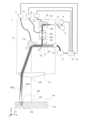
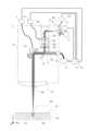
本開示の実施の形態に係るレーザ加工装置1の構成について、図1を用いて説明する。図1は、本実施の形態のレーザ加工装置1の構成を模式的に示す図である。[Configuration of laser processing device]
A configuration of a
レーザ加工装置1は、加工ヘッド2、光干渉計3、計測処理部4、レーザ発振器5、制御部6、第1ドライバ7、第2ドライバ8、第3ドライバ41を有する。 The
光干渉計3は、OCT測定用の測定光15を出射する。出射された測定光15は、測定光導入口9から加工ヘッド2へ入力される。測定光導入口9は、第2ミラー17上に設置されている。 The
レーザ発振器5は、レーザ加工用の加工用レーザ光11を発振する。発振された加工用レーザ光11は、加工光導入口10から加工ヘッド2へ入力される。 A
加工ヘッド2へ入力された加工用レーザ光11は、ダイクロイックミラー12を透過し、第1ミラー13で反射され、レンズ14を透過し、被加工物18の表面の加工面19に集光される。これにより、被加工物18の加工点20がレーザ加工される。この際、加工用レーザ光11が照射された加工点20は溶融し、溶融池21が形成される。また、溶融池21から溶融金属が蒸発し、蒸発時に生じる蒸気の圧力によってキーホール22が形成される。 The
加工ヘッド2へ入力された測定光15は、コリメートレンズ16で平行光に変換され、第2ミラー17で反射された後、ビームシフト機構38を透過する。その後、測定光15は、ダイクロイックミラー12で反射された後、第1ミラー13で反射され、レンズ14を透過し、被加工物18の表面の加工点20に集光される。そして、測定光15は、キーホール22の底面で反射され、伝播経路を遡って光干渉計3まで到達し、光干渉計3内で図示しない参照光との光干渉による干渉信号を発生させる。 The
計測処理部4は、干渉信号からキーホール22の深さ、すなわち加工点20の溶け込み深さを計測する。なお、溶け込み深さとは、被加工物18の溶けた部分の最頂点と、加工面19との間の距離を意味する。 The
加工用レーザ光11の波長と測定光15の波長とは、互いに異なる。ダイクロイックミラー12は、加工用レーザ光11の波長の光を透過し、測定光15の波長の光を反射する特性を有する。 The wavelength of the
例えば、加工用レーザ11としてYAGレーザまたはファイバレーザを用いた場合、加工用レーザ11の波長は、1064nmである。また、例えば、測定光15としてOCT用光源を用いた場合、測定光15の波長は、1300nmである。 For example, when a YAG laser or fiber laser is used as the
第1ミラー13および第2ミラー17は、2軸以上で回転動作させることができる可動ミラーである。第1ミラー13および第2ミラー17は、例えば、ガルバノミラーである。 The
第1ミラー13、第2ミラー17は、それぞれ、第1ドライバ7、第2ドライバ8を介して制御部6に接続されており、制御部6の制御に基づいて動作する。第1ドライバ7は、制御部6からの指示に基づいて、第1ミラー13を動作させる。第2ドライバ8は、制御部6からの指示に基付いて、第2ミラー17を動作させる。 The
制御部6は、メモリ31を有する。メモリ31は、被加工物18に対して所望の加工を行うための加工データ、および、後述する補正を行うための補正用データを記憶する。 The
図1では例として、第1ミラー13および第2ミラー17のそれぞれについて、y方向の回転軸を中心とした回転動作のみを示している(図中の点線部分および両矢印参照)。しかし、実際には、第1ミラー13および第2ミラー17は、それぞれ、上述したように2軸以上で回転動作できるように構成されている。よって、第1ミラー13および第2ミラー17は、それぞれ、例えば、x方向の回転軸を中心とした回転動作を行うことも可能である。 As an example, FIG. 1 shows only the rotational movement of each of the
以下では、簡単を簡単にするため、第1ミラー13および第2ミラー17のそれぞれがy方向の回転軸を中心とした回転動作を行う場合についてのみ説明する。 For the sake of simplification, only the case where each of the
第2ミラー17が原点位置にあるとき、測定光15の測定光軸23は、ダイクロイックミラー12で反射された後、加工用レーザ光11の加工光軸24と一致する。 When the
また、第1ミラー13が原点位置にあるとき、加工用レーザ光11の加工光軸24は、第1ミラー13にて反射された後、レンズ14を透過する際に、レンズ14の中心であるレンズ光軸25と一致する。 Further, when the
なお、以下の説明では、レンズ14の中心を透過した加工用レーザ光11および測定光15が被加工物18の加工面19に到達した位置(照射位置と言ってもよい)を、「加工原点26」(図2参照)と記載する。すなわち、第1ミラー13、第2ミラー17それぞれの原点位置とは、加工用レーザ光11および測定光15がレンズ14の中心を透過する位置である。 In the following description, the position (which may be called the irradiation position) at which the
レンズ14は、加工用レーザ光11および測定光15を加工点20に集光するためのレンズである。レンズ14は、例えば、fθレンズである。 The
第1ミラー13およびレンズ14は、ガルバノミラーとfθレンズとによる一般的な光学走査系を構成している。このため、第1ミラー13をその原点位置から所定の角度だけ回転させることにより、加工用レーザ光11の加工面19への到達位置を制御することができる。以下では、第1ミラー13をその原点位置から回転させる角度を「第1ミラー13の動作量」という。なお、所望の加工点20へ加工用レーザ光11を照射させるための第1ミラー13の動作量は、加工ヘッド2を構成する各光学部材の位置関係と、レンズ14から加工面19までの距離とが決まれば、一意に設定することができる。 The
レンズ14から加工面19までの距離は、加工用レーザ光11による加工が最も効率的に行われるように、加工用レーザ光11が最も集光される焦点位置と、加工面19とを一致させた距離とすることが好ましい。ただし、これに限定されず、レンズ14から加工面19までの距離は、加工用途に応じて任意の距離に決定されればよい。 The distance from the
第1ミラー13の動作量を所定の動作スケジュールで変化させることで、加工面19上で加工点20の位置を走査することができる。さらに、制御部6の制御によりレーザ発振器5のオンとオフの切り替えが行われることにより、加工用レーザ光11の走査可能な範囲内における、加工面19上の任意の位置を任意のパターンでレーザ加工することができる。 The position of the
ビームシフト機構38は、測定光15の測定光軸23を2軸以上で平行移動させるための機構である。例えば、ビームシフト機構38は、平行移動ステージである。ビームシフト機構38は、第2ミラー17が原点位置にあるときの測定光15の測定光軸23に対して垂直な方向(図中のxy軸、および、図中の直線状の両矢印参照)に2軸以上で平行移動できるように構成されている。 The
ビームシフト機構38は、第3ドライバ41を介して制御部6に接続されており、制御部6の制御に基づいて動作する。第3ドライバ41は、制御部6からの指示に基づいて、ビームシフト機構38を動作させる。 The
また、ビームシフト機構38には、第1レンズ39および第2レンズ40が設置されている。第1レンズ39の主点と第2レンズ40の主点との間の距離は、2つのレンズの焦点距離を足した距離に設定されている。 A
また、本実施の形態では、第1レンズ39の焦点距離と第2レンズ40の焦点距離とが同じであるとする。 Also, in this embodiment, the focal length of the
また、ビームシフト機構38が原点位置で、かつ、第2ミラー17が原点位置にあるとき、測定光15の測定光軸23は、ダイクロイックミラー12で反射された後に加工用レーザ光11の加工光軸24と一致する。 Further, when the
[色収差による影響]
次に、図2を用いて、色収差による影響について説明する。図2は、第1ミラー13を原点位置から動作させた状態のレーザ加工装置1を模式的に示す図である。図2において、第2ミラー17は原点位置にあるとする。[Influence of Chromatic Aberration]
Next, the influence of chromatic aberration will be described with reference to FIG. FIG. 2 is a diagram schematically showing the
図2に示すように、第1ミラー13で反射された加工用レーザ光11および測定光15は、レンズ14に到達するまでは同じ光軸上を進む。しかしながら、レンズ14を透過した後では、加工用レーザ光11と測定光15の進行方向にずれが生じる。すなわち、図2に示すように、加工用レーザ光11の光軸である加工光軸24aと、測定光15の光軸である測定光軸23aとがずれる。よって、測定光15は、加工点20とは異なる位置に到達する。 As shown in FIG. 2, the
これは、レンズ14の色収差が原因である。色収差とは、レンズ14を含む一般的な光学材料が、光の波長により屈折率が異なる性質を有するために発生する収差である。 This is due to the chromatic aberration of
色収差には、軸上色収差と、倍率色収差との二種類がある。軸上色収差は、光の波長によりレンズの焦点位置が異なる性質を指す。一方、倍率色収差は、光の波長により焦点面における像高が異なる性質を指す。図2に示した、レンズ14透過後の加工用レーザ光11(加工光軸24a)と測定光15(測定光軸23a)の進行方向のずれは、倍率色収差によるものである。 There are two types of chromatic aberration: longitudinal chromatic aberration and lateral chromatic aberration. Axial chromatic aberration refers to the property that the focal position of a lens differs depending on the wavelength of light. On the other hand, the chromatic aberration of magnification refers to the property that the image height on the focal plane differs depending on the wavelength of light. The deviation in the direction of travel between the processing laser light 11 (processing
なお、本実施の形態のレーザ加工装置1では、軸上色収差も同時に発生している。しかしながら、軸上色収差による加工用レーザ光11と測定光15のずれについては、コリメートレンズ16と測定光導入口9との距離を調節し、コリメートレンズ16を透過直後の測定光15を平行光の状態からわずかに発散状態または収束状態にすることで対応が可能である。 In addition, in the
図2では、加工原点26から見て、測定光15が加工面19に到達した位置は、加工用レーザ光11が加工面19に到達した位置よりも遠い。しかしながら、これは一例であり、レンズ14のレンズ構成や加工用レーザ光11と測定光15との波長の大小関係により、測定光15の方が加工用レーザ光11よりも加工原点26に近い位置に到達する場合もある。一般的には、長波長の光の方が、より加工原点26から遠い位置に到達する。 In FIG. 2 , the position where the
倍率色収差を補正する方法として、例えば、レンズ14に色消しレンズの性質を持たせる方法がある。しかし、レンズ14に、fθレンズとしての性質と、色消しレンズとしての性質を両方持たせようとすると、非常に高度な光学設計技術が必要となり、レンズ14の設計に多大な時間とコストとが掛かってしまう。このため、本実施の形態では、以下に説明するように、第2ミラー17を動作させることにより、低コストで倍率色収差を補正している。 As a method of correcting the chromatic aberration of magnification, for example, there is a method of giving the
[倍率色収差の補正方法]
次に、図3を用いて、倍率色収差の補正方法について説明する。図3は、倍率色収差による加工用レーザ光11および測定光15それぞれの到達位置のずれを補正した状態のレーザ加工装置1を模式的に示す図である。[Method for correcting lateral chromatic aberration]
Next, a method for correcting chromatic aberration of magnification will be described with reference to FIG. FIG. 3 is a diagram schematically showing the
図3では、第2ミラー17を、原点位置から所定の動作量(動作角度と言ってもよい)だけ動作させている。これにより、図3に示すように、ダイクロイックミラー12からレンズ14に到るまでの間において、加工用レーザ光11の加工光軸24と、測定光15の測定光軸23とが同軸ではなくなる。しかしながら、加工用レーザ光11および測定光15は、それぞれ、レンズ14を透過した後、加工面19における同じ位置、すなわち加工点20に到達している。 In FIG. 3, the
図3において、加工用レーザ光11の加工光軸24aは、図2に示した加工光軸24aと同じ位置を通っている。一方、図3において、第2ミラー17の動作により補正された測定光15の測定光軸23bは、図2に示した測定光軸23aとは異なる位置を通っている。 In FIG. 3, the processing
第2ミラー17の動作量(すなわち、第2ミラー17をその原点位置から回転させる角度)は、第1ミラー13の動作量と1対1に対応付けられている。第1ミラー13の動作量は、加工用レーザ光11(および測定光15)を照射する加工点20の位置によって一意に決まっているため、第2ミラー17の動作量も、測定光15を照射する加工点20の位置によって一意に決まる。なお、以下では、第2ミラー17の動作量を「補正角」と記載し、その補正角の求め方について説明する。 The amount of movement of the second mirror 17 (that is, the angle by which the
[補正角と走査角との関係]
次に、補正角と走査角との関係について説明する。fθレンズであるレンズ14では、レンズ14の焦点距離をfとし、レンズ14に入射する光のレンズ光軸25からの角度をθとし、レンズ14を透過した光線の像面における光軸からの距離(以下、像高という)をhとした場合、h=fθという関係が成り立つ。[Relationship Between Correction Angle and Scanning Angle]
Next, the relationship between the correction angle and the scanning angle will be explained. In the
上述したように、第1ミラー13は、回転動作する軸を2軸有している。この2軸を仮にx軸、y軸とし、第1ミラー13で反射された光のレンズ光軸25からのx軸成分の角度をθxとし、同じくレンズ光軸25からのy軸成分の角度をθyとする。そして、像面におけるx方向、y方向の像高をそれぞれx、yとした場合、x=fθx、y=fθyという関係が成り立つ。 As described above, the
したがって、加工用レーザ光11が加工面19に到達する加工点の位置を(x,y)とすると、(x,y)=(fθx,fθy)となる。また、ミラーへ光を入射させたときのミラーからの反射光の出射角度は、2倍の角度量で変化する。そのため、第1ミラー13の動作量を(φx,φy)とした場合、(2φx,2φy)=(θx,θy)の関係が成り立つ。なお、以下の説明では、第1ミラー13の動作量(φx,φy)を「走査角」と記載する。 Therefore, when the position of the processing point where the
このように、本実施の形態のレーザ加工装置1では、第1ミラー13の走査角(φx,φy)が決定されると、加工用レーザ光11の加工面19における到達位置、すなわち加工点20の位置(x,y)も決定される。 As described above, in the
上述したように、走査角は加工点20の位置によって一意に決定され、同様に補正量も加工点20の位置によって一意に決定される。すなわち、ある加工点20の位置毎に走査角と補正量との関係を予め算出しておき、加工時には加工点20の位置に対応する補正量だけ第2ミラー17を動作させることにより、上述した倍率色収差による測定光15のずれを補正することができる。 As described above, the scanning angle is uniquely determined by the position of the
[キーホール角度の影響]
一方で、図3に示したように、倍率色収差による加工用レーザ光11および測定光15それぞれの到達位置のずれを補正した状態であっても、加工用レーザ光11の加工光軸24aと測定光15の測定光軸23bは一致しない。[Influence of keyhole angle]
On the other hand, as shown in FIG. 3, even in a state in which the displacement of the respective arrival positions of the
加工用レーザ光11の走査速度(以下、加工速度という)が遅い場合では、キーホール22の形成方向と加工用レーザ光11の加工光軸24aとが一致するため、測定光15はキーホール22の形成方向に対して斜めに入射することになる。これにより、測定光15がキーホール22の底まで到達できない場合が生じる。その結果、キーホール22の深さの測定精度が悪化する。 When the scanning speed of the processing laser beam 11 (hereinafter referred to as processing speed) is slow, the forming direction of the
図4に加工速度が速い場合のキーホール22の形成状態の一例を模式的に示す。加工用レーザ光11の加工光軸24aがx軸の正方向に移動している場合、キーホール22は、そのキーホール形成軸42が加工点20を起点として加工方向(x軸の正方向)に傾いた状態で形成される。このため、倍率色収差による加工用レーザ光11および測定光15それぞれの到達位置のずれを補正した状態であっても、測定光15がキーホール22の底まで到達できない場合が生じる。その結果、キーホール22の深さの測定精度が悪化する。 FIG. 4 schematically shows an example of how the
特に、レーザ発振器5のビームモードがシングルモードである場合では、加工用レーザ光11の加工点20におけるスポット径が例えば50um以下と小さくなる。そのため、発生するキーホール22の直径も小さくなり、キーホール22のキーホール形成軸42の角度と測定光15の測定光軸23bの角度とのずれは、キーホール22の深さの測定精度を大きく悪化させる要因となる。 In particular, when the beam mode of the
そこで、本実施の形態では、以下に説明するように、ビームシフト機構38を動作させることにより、測定光15の測定光軸23bの角度を補正し、測定光軸23bとキーホール形成軸42とを一致させるようにした。 Therefore, in the present embodiment, as described below, the
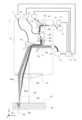
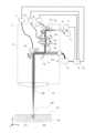
[測定光軸の角度の補正方法]
次に、図5を用いて、測定光軸の角度の補正方法について説明する。図5は、図3に示したキーホール形成軸42および測定光15の測定光軸23bそれぞれの角度のずれを補正した状態のレーザ加工装置1を模式的に示す図である。[How to correct the angle of the measurement optical axis]
Next, a method for correcting the angle of the measurement optical axis will be described with reference to FIG. FIG. 5 is a diagram schematically showing the
図5では、ビームシフト機構38を原点位置から所定の動作量(動作距離と言ってもよい)だけ動作させている。これにより、ダイクロイックミラー12からレンズ14に到るまでの間、測定光15の測定光軸23は加工用レーザ光11の加工光軸24に対して平行にシフトする。しかしながら、加工用レーザ光11および測定光15は、レンズ14を透過した後、加工面19において、同じ加工点20に到達している。 In FIG. 5, the
図5において、加工用レーザ光11の加工光軸24aは、図3に示した加工光軸24aと同じ位置を通っている。また、図5において、測定光軸23cは、図3に示した測定光軸23bをビームシフト機構38の動作によって補正したものである。図5に示す測定光軸23cの角度は、図3に示した測定光軸23bの角度とは異なり、キーホール22のキーホール形成軸42の角度と一致している。 In FIG. 5, the processing
ビームシフト機構38を原点位置から動作させる所定の動作量(以下、補正移動量と記載する)は、第1ミラー13の動作量および加工速度と対応付けられている。第1ミラー13の動作量および加工速度は、加工用レーザ光11(および測定光15)を照射する加工点20の位置によって一意に決まっているため、補正移動量も、測定光15を照射する加工点20の位置によって一意に決まる。すなわち、加工点20の位置毎に走査角と補正移動量との関係を予め算出しておき、加工時において、加工点20の位置に対応する補正移動量だけビームシフト機構38を動作させることにより、図3に示したキーホール形成軸42と測定光軸23bそれぞれの角度ずれを補正することができる。 A predetermined movement amount (hereinafter referred to as a correction movement amount) for moving the
[第1の補正数表データの作成方法]
第1の補正数表データの作成方法について説明する。第1の補正数表データは、加工点20毎に走査角と補正角との対応関係を示すデータである。第1の補正数表データは、補正角の補正数表データと言ってもよい。[Method of Creating First Correction Table Data]
A method for creating the first correction formula table data will be described. The first correction mathematical table data is data indicating the correspondence relationship between the scanning angle and the correction angle for each
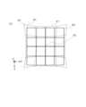
まず、図6を用いて、加工面19上の加工用レーザ光11および測定光15それぞれの軌跡について説明する。図6は、第2ミラー17を動作させずに第1ミラー13のみを動作させて被加工物18の表面(すなわち、加工面19)を格子状に走査した場合における、加工面19上の加工用レーザ光11および測定光15それぞれの軌跡を模式的に示す図である。図6は、加工面19をレンズ14側から見た状態を示している。 First, trajectories of the
図6では、加工用レーザ光11の軌跡である加工光軌跡28が実線で示され、測定光15の軌跡である測定光軌跡27が点線で示されている。図6に示す例では、第2ミラー17が動作していないため、倍率色収差の補正が行われていない。したがって、加工原点26付近では加工用レーザ光11および測定光15それぞれの軌跡は一致しているが、加工原点26から遠ざかるにつれて両者のずれが大きくなっている。これにより、加工光軌跡28は歪みのない格子状パターンを描く一方、測定光軌跡27は歪んだ糸巻き型の軌跡を描いている。なお、図6に示す測定光軌跡27の形状は一例であり、測定光軌跡27の歪み形状はレンズ14の光学特性によって変化しうる。 In FIG. 6, a
また、加工光軌跡28および測定光軌跡27それぞれに対応する位置のずれ量も同様にレンズ14の光学特性や光学設計に依存する。一般的な例としては、焦点距離が250mmであり、加工面領域が直径200mm程度である市販のfθレンズでは、加工面領域の最外周付近において0.2mmから0.4mmのずれが生じる。 Similarly, the amount of positional deviation corresponding to each of the
それに対して、加工用レーザ光11を加工点20に照射することで生成されるキーホール22(例えば、図1参照)の直径は、加工用レーザ光のパワーや品質にも依るが、おおむね0.03mmから0.2mmと小さい。このことから、レンズ14の色収差により生じる加工用レーザ光11と測定光15との位置ずれによって、キーホール22の底面に測定光15が到達せず、正しい溶け込み深さが測定できなくなる。 On the other hand, the diameter of the keyhole 22 (see, for example, FIG. 1) generated by irradiating the
なお、図6では一例として、等間隔の4×4マスの格子状パターンを図示しているが、本開示はこれに限定されない。走査のための格子状パターンは、より細かいマス数の格子に設定されたり、fθレンズの倍率色収差特性に関連して特に精度の必要な領域の格子間隔を狭くされたりしてもよい。また、放射状の格子状パターンが設定されてもよい。ただし、本実施の形態では、補正角はx軸およびy軸の2軸で設定されるため、図6に示した直交格子状のパターンがより好適である。 Note that FIG. 6 illustrates a grid pattern of 4×4 squares at regular intervals as an example, but the present disclosure is not limited to this. The grid-like pattern for scanning may be set to a grid with a finer number of cells, or the grid spacing may be narrowed in a region that particularly requires precision in relation to the chromatic aberration of magnification characteristic of the fθ lens. Also, a radial lattice pattern may be set. However, in this embodiment, since the correction angle is set along the two axes of the x-axis and the y-axis, the orthogonal lattice pattern shown in FIG. 6 is more suitable.
図6に示す加工光軌跡28と測定光軌跡27とを比較すると、格子状パターンの対応する各格子点においてずれが生じていることが分かる。 Comparing the
補正数表データを作成するためには、加工光軌跡28上のある1つの格子点である加工光格子点30と、測定光軌跡27の対応する測定光格子点29とが一致するように補正量を決定する必要がある。 In order to create the correction formula data, correction is made so that the processing
次に、第1の補正数表データの作成方法の流れについて説明する。 Next, the flow of the method for creating the first correction formula table data will be described.
まず、図7を用いて、第1の補正数表データの作成方法の第1の例について説明する。図7は、第1の補正数表データの作成方法の第1の例を示すフローチャートである。 First, with reference to FIG. 7, a first example of a method for creating first correction formula table data will be described. FIG. 7 is a flow chart showing a first example of a method for creating the first correction formula table data.
ステップS1において、制御部6は、被加工物18の加工面19に対して、レーザ加工を行う範囲である格子状パターン(例えば、図6に示した加工光軌跡28)を設定する。また、制御部6は、格子状パターンに含まれる複数の格子点のうち、1つの格子点を選定する。 In step S<b>1 , the
ステップS2において、制御部6は、選定された格子点に2次元ビームプロファイラ(図示せず)を設置する。このとき、2次元ビームプロファイラの検出面の高さ位置は、加工面19と一致するように設置される。 At step S2, the
ステップS3において、制御部6は、選定された格子点に加工用レーザ光11が到達するように第1ミラー13の走査角を設定する。 In step S3, the
ステップS4において、制御部6は、加工用レーザ光11を照射させ、2次元ビームプロファイラを用いて、実際に加工用レーザ光11が加工面19に到達した位置(以下、加工用レーザ光11の到達位置という)を求める。 In step S4, the
ステップS5において、制御部6は、測定光15を照射させ、2次元ビームプロファイラを用いて、実際に測定光15が加工面19に到達した位置(以下、測定光15の到達位置という)を求める。 In step S5, the
ステップS6において、制御部6は、加工用レーザ光11の到達位置と測定光15の到達位置とが一致するように、2次元ビームプロファイラの測定結果を参照しながら、第2ミラー17の補正角を設定する。 In step S6, the
ステップS7において、制御部6は、ステップS3で設定した走査角と、ステップS6で設定した補正角とを、補正数表データとしてメモリ31に保存する。 In step S7, the
ステップS8において、制御部6は、格子状パターンのすべての格子点において補正数表データを保存したか否かを判定する。すべての格子点において補正数表データを保存した場合(ステップS8:YES)、フローは、終了する。一方、すべての格子点において補正数表データを保存していない場合(ステップS8:NO)、フローは、ステップS9へ進む。 In step S8, the
ステップS9において、制御部6は、新たな格子点(すなわち、補正数表データの保存が行われていない格子点)を1つ選定する。その後、フローは、ステップS2に戻る。 In step S9, the
以上、第1の補正数表データの作成方法の第1の例について説明した。 The first example of the method for creating the first correction table data has been described above.
次に、図8を用いて、第1の補正数表データの作成方法の第2の例について説明する。図8は、第1の補正数表データの作成方法の第2の例を示すフローチャートである。 Next, with reference to FIG. 8, a second example of the method for creating the first correction formula table data will be described. FIG. 8 is a flow chart showing a second example of the method of creating the first correction formula table data.
本例では、仮の被加工物として、例えば金属の平板(以下、金属板という)が用いられる。 In this example, for example, a metal flat plate (hereinafter referred to as a metal plate) is used as the temporary workpiece.
ステップS11において、制御部6は、金属板の加工面19に対して、レーザ加工を行う範囲である格子状パターン(例えば、図6に示した加工光軌跡28)を設定する。また、制御部6は、格子状パターンに含まれる複数の格子点のうち、1つの格子点を選定する。 In step S11, the
ステップS12において、制御部6は、選定された格子点に加工用レーザ光11が到達するように第1ミラー13の走査角を設定する。 In step S12, the
ステップS13において、制御部6は、選定された格子点に対して加工用レーザ光11を照射させ、金属板の表面に微小穴を開ける。このとき、加工用レーザ光11の出力強度および照射時間は、金属板を貫通しないように調整される。また、ここで形成される微小穴の直径は、光干渉計3の計測分解能に比べて2~3倍程度であることが好ましい。 In step S13, the
ステップS14において、制御部6は、形成された微小穴の形状の測定を光干渉計3に実行させる。この際、第2ミラー17を原点位置からある程度動作させて測定光15を走査することにより、微小穴近傍の3次元的な形状を測定することができる。 In step S14, the
ステップS15において、制御部6は、ステップS14で測定された結果を示すデータを用いて、測定光15を微小穴の最深部に到達させることができる第2ミラー17の補正角を求める。 In step S15, the
ステップS16において、制御部6は、ステップS12で設定した走査角と、ステップS15で求めた補正角とを、補正数表データとしてメモリ31に保存する。 In step S16, the
ステップS17において、制御部6は、格子状パターンのすべての格子点において補正数表データを保存したか否かを判定する。すべての格子点において補正数表データを保存した場合(ステップS17:YES)、フローは、終了する。一方、すべての格子点において補正数表データを保存していない場合(ステップS17:NO)、フローは、ステップS18へ進む。 In step S17, the
ステップS18において、制御部6は、新たな格子点(すなわち、補正数表データの保存が行われていない格子点)を1つ選定する。その後、フローは、ステップS12に戻る。 In step S18, the
以上、第1の補正数表データの作成方法の第2の例について説明した。 The second example of the method for creating the first correction table data has been described above.
以上説明した第1の例または第2の例により、第1の補正数表データが得られる。なお、ステップS1またはステップS11設定される格子状パターンが図6に示した4×4の格子状パターンである場合では、16個の格子点における補正数表データしか作成できない。そこで、格子点を16個以上含む格子状パターンを設定することにより、より多くの補正数表データを作成することが好ましい。 The first correction table data is obtained by the first example or the second example described above. If the lattice pattern set in step S1 or step S11 is the 4×4 lattice pattern shown in FIG. 6, only 16 lattice points can be used to create correction mathematical table data. Therefore, it is preferable to create more correction table data by setting a lattice pattern including 16 or more lattice points.
ただし、多くの補正数表データを作成したとしても、第1ミラー13の走査角は機構上の動作範囲内であればどのような値でも設定することができるため、走査角が補正数表データと一致しない場合が生じうる。このような場合には、補正数表データを補間して補正角を求める必要がある。この補正数表データを補間して補正角を求める方法については、後述する。 However, even if many correction formula table data are created, the scanning angle of the
[第2の補正数表データの作成方法]
第2の補正数表データの作成方法について説明する。第2の補正数表データは、走査角と補正移動量との対応関係を示すデータである。補正移動量は、上述したとおり、加工点20の位置(以下、加工位置という)および加工速度に対応している。[Method of Creating Second Correction Table Data]
A method of creating the second correction formula table data will be described. The second correction mathematical table data is data indicating the correspondence relationship between the scanning angle and the correction movement amount. As described above, the correction movement amount corresponds to the position of the machining point 20 (hereinafter referred to as machining position) and machining speed.
第2の補正数表データの作成は、上述した第1の補正数表データの作成後に行われる。また、第2の補正数表データは、加工位置と加工速度とに分けて作成される。以下、加工位置に関する補正移動量を「位置補正移動量」といい、加工速度に関する補正移動量を「速度補正移動量」という。本実施の形態では、第2の補正数表データとして、位置補正移動量の補正数表データおよび速度補正移動量の補正数表データが作成される。 The creation of the second correction mathematical table data is performed after the creation of the first correction mathematical table data described above. Also, the second correction mathematical table data is created separately for the machining position and the machining speed. Hereinafter, the corrected movement amount regarding the machining position will be referred to as "position correction movement amount", and the correction movement amount regarding the machining speed will be referred to as "speed correction movement amount". In this embodiment, as the second correction mathematical table data, the correction mathematical table data for the position correction movement amount and the correction mathematical table data for the speed correction movement amount are created.
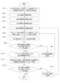
まず、図9を用いて、位置補正移動量の補正数表データを作成する方法の流れについて説明する。図9は、位置補正移動量の補正数表データを作成する方法の例を説明するフローチャートである。 First, with reference to FIG. 9, the flow of the method for creating correction mathematical table data for the amount of position correction movement will be described. FIG. 9 is a flow chart for explaining an example of a method for creating correction mathematical table data for position correction movement amounts.
本例では、仮の被加工物として、例えば金属の平板(以下、金属板という)が用いられる。 In this example, for example, a metal flat plate (hereinafter referred to as a metal plate) is used as the temporary workpiece.
ステップS21において、制御部6は、金属板の加工面19に対して、レーザ加工を行う範囲である格子状パターン(例えば、図6に示した加工光軌跡28)を設定する。また、制御部6は、格子状パターンに含まれる複数の格子点のうち、1つの格子点を選定する。 In step S21, the
ステップS22において、制御部6は、選定された格子点に加工用レーザ光11が到達するように第1ミラー13の走査角を設定する。 In step S22, the
ステップS23において、制御部6は、選定された格子点に測定光15が到達するように第2ミラー17の補正角を設定する。ここでの補正角は、上述した第1の補正数表データとして保存された値である。 In step S23, the
ステップS24において、制御部6は、選定された格子点に対して加工用レーザ光11を照射させ、金属板の表面に微小穴を開ける。このとき、加工用レーザ光11の出力強度および照射時間は、金属板を貫通しないように調整される。また、ここで形成される微小穴の直径は、光干渉計3の計測分解能に比べて2~3倍程度であることが好ましい。 In step S24, the
ステップS25において、制御部6は、ビームシフト機構38に測定光軸23の角度を走査させ、キーホール22の深さの測定値が最大になる位置補正移動量を求める。 In step S25, the
ステップS26において、制御部6は、ステップS22で設定した走査角と、ステップS25で求めた位置補正移動量とを、補正数表データとしてメモリ31に保存する。 In step S26, the
ステップS27において、制御部6は、格子状パターンのすべての格子点において補正数表データを保存したか否かを判定する。すべての格子点において補正数表データを保存した場合(ステップS27:YES)、フローは、終了する。一方、すべての格子点において補正数表データを保存していない場合(ステップS27:NO)、フローは、ステップS28へ進む。 In step S27, the
ステップS28において、制御部6は、新たな格子点(すなわち、補正数表データの保存が行われていない格子点)を1つ選定する。その後、フローは、ステップS22に戻る。 In step S28, the
上述した方法により、位置補正移動量の補正数表データが得られる。なお、ステップS21で設定される格子状パターンは、上述した第1の補正数表データの作成方法で設定される格子状パターンと同じである。よって、走査角が補正数表データと一致しない場合には、上記第1の補正数表データの作成方法での説明と同様の方法により、補正数表データを補間して位置補正移動量を求めることができる。 By the method described above, the correction mathematical table data of the position correction movement amount is obtained. Note that the lattice pattern set in step S21 is the same as the lattice pattern set in the above-described method for creating the first correction formula table data. Therefore, when the scanning angle does not match the correction mathematical table data, the correction mathematical table data is interpolated by the same method as described in the first correction mathematical table data creation method to obtain the position correction movement amount. be able to.
また、本実施の形態では、位置補正移動量の補正数表データと第1の補正数表データ(補正角の補正数表データ)とを合わせて、加工位置の補正数表として設定されている。 Further, in the present embodiment, the correction mathematical table data of the position correction movement amount and the first correction mathematical table data (correction numerical table data of the correction angle) are combined and set as the correction mathematical table of the machining position. .
次に、図10を用いて、速度補正移動量の補正数表データを作成する方法の流れについて説明する。図10は、位置補正移動量の補正数表データを作成する方法の例を説明するフローチャートである。 Next, with reference to FIG. 10, the flow of the method for creating the correction formula table data for the speed correction movement amount will be described. FIG. 10 is a flowchart for explaining an example of a method for creating correction mathematical table data for position correction movement amounts.
本例では、仮の被加工物として、金属板が用いられる。 In this example, a metal plate is used as the temporary workpiece.
ステップS31において、制御部6は、加工原点26(図2、図3参照)を含んだ走査ラインを通る第1ミラーの走査角と第2ミラーの補正角とを設定する。例えば、走査ラインとしては、加工原点26を通るx軸上のラインを用い、走査角と補正角としては、第1の補正数表データとして保存された値を用いる。 In step S31, the
ステップS32において、制御部6は、加工速度の範囲を設定する。例えば、制御部6は、被加工物18を加工するための加工データに含まれる加工速度の最大値から最小値までを加工速度の範囲に設定する。 In step S32, the
ステップS33において、制御部6は、補正移動量の範囲を設定する。例えば、制御部6は、加工点20へ入射する測定光15の測定光軸23の角度が走査方向に±10degとなる範囲を補正移動量の範囲に設定する。 In step S33, the
ステップS34において、制御部6は、加工速度の初期値を設定する。例えば、加工速度の初期値としては、加工速度の範囲の最小値が設定される。 In step S34, the
ステップS35において、制御部6は、補正移動量の初期値を設定する。例えば、補正移動量の初期値としては、補正移動量の範囲の最小値が設定される。 In step S35, the
ステップS36において、制御部6は、設定した加工速度の加工用レーザ光11および測定光15により走査ライン上を同時に走査し、キーホール22の深さを測定する。 In step S36, the
ステップS37において、制御部6は、ステップS36で測定したキーホール22の深さのうち、加工原点26の位置のキーホール22の深さを記録する。 In step S37, the
ステップS38において、制御部6は、ステップS33で設定した補正移動量の範囲に含まれる全ての値に対応するデータを取得したか否かを判定する。ここでいうデータとは、加工原点26の位置のキーホール22の深さを示すデータである。 In step S38, the
補正移動量の範囲の全ての値に対応するデータを取得した場合(ステップS38:YES)、フローは、ステップS310へ進む。一方、補正移動量の範囲の全ての値に対応するデータを取得していない場合(ステップS38:NO)、フローは、ステップS39へ進む。 If data corresponding to all values in the range of the correction movement amount have been acquired (step S38: YES), the flow proceeds to step S310. On the other hand, if data corresponding to all values in the range of the correction movement amount have not been acquired (step S38: NO), the flow proceeds to step S39.
ステップS39において、制御部6は、別の補正移動量を設定する。その後、フローは、ステップS36に戻る。 In step S39, the
ステップS310において、制御部6は、ステップS37で記録されたキーホール22の深さに基づいて、キーホール22の深さが最大になる補正移動量を求める。 In step S310, the
ステップS311において、制御部6は、現在の加工速度と、ステップS310で求めたキーホール22の深さが最大になる補正移動量とを、速度補正移動量の補正数表データとしてメモリ31に保存する。 In step S311, the
ステップS312において、制御部6は、ステップS32で設定した加工速度の範囲に含まれる全ての値に対応するデータを取得したか否かを判定する。ここでいうデータとは、現在の加工速度およびキーホール22の深さが最大になる補正移動量を示す補正数表データである。 In step S312, the
加工速度の範囲に含まれる全ての値に対応するデータを取得した場合(ステップS312:YES)、フローは、終了する。一方、加工速度の範囲に含まれる全ての値に対応するデータを取得していない場合(ステップS312:NO)、フローは、ステップS313へ進む。 If the data corresponding to all the values included in the machining speed range have been obtained (step S312: YES), the flow ends. On the other hand, if data corresponding to all values included in the machining speed range have not been acquired (step S312: NO), the flow proceeds to step S313.
ステップS313において、制御部6は、別の加工速度を設定する。その後、フローは、ステップS35に戻る。 In step S313, the
上述した方法により、速度補正移動量の補正数表データが得られる。 By the method described above, the correction formula table data of the speed correction movement amount is obtained.
図11に速度補正移動量の補正数表データの一例を示す。図11に示すように、速度補正移動量の補正数表データでは、加工速度Vkとm速度補正移動量|DVk|とが対応付けられている。図11において、速度補正移動量|DVk|は、走査方向の傾きの大きさとして記録されている。FIG. 11 shows an example of correction mathematical table data of the speed correction movement amount. As shown in FIG. 11, in the correction mathematical table data of the speed correction movement amount, the machining speed Vk and the m speed correction movement amount |DVk | are associated with each other. In FIG. 11, the velocity correction movement amount |DVk | is recorded as the magnitude of the tilt in the scanning direction.
なお、本実施の形態においては、図11に示した速度補正移動量の補正数表データは、加工速度の補正数表として用いられる(後述の図17参照)。 In this embodiment, the correction formula table data for the speed correction movement amount shown in FIG. 11 is used as the correction formula table for the machining speed (see FIG. 17 described later).
[加工データの作成方法]
次に、被加工物18を加工するための加工データの作成方法について説明する。[How to create processing data]
Next, a method of creating machining data for machining the
従来、fθレンズおよびガルバノミラーを有するレーザ加工装置では、制御部が、時系列に設定された複数の加工データ(例えば、レーザ発振器への出力指示値と、走査角および加工速度のデータ項目とが加工点毎にセットになったデータ)を用いてレーザ発振器およびガルバノミラーを制御していた。これにより、被加工物の表面の各加工点に対して時系列で加工が行われていた。 Conventionally, in a laser processing apparatus having an fθ lens and a galvanomirror, a plurality of processing data set in time series (for example, an output instruction value to a laser oscillator, a scanning angle, and a processing speed data item) are set by a control unit. A set of data for each processing point) was used to control the laser oscillator and galvanomirror. As a result, each machining point on the surface of the workpiece is machined in time series.
本実施の形態では、レーザ加工装置1が用いる加工データのデータ項目として、レーザ発振器5への出力指示値(レーザ出力データともいう)、加工点20の位置(加工点位置ともいう)、加工速度、走査角のほか、補正角、補正移動量が加えられる。以下の説明では、このように補正角および補正移動量がデータ項目として加えられた加工データを「補正済み加工データ」と記載する。 In the present embodiment, data items of the processing data used by the
ここで、図12を用いて、補正済み加工データの一例について説明する。図12は、補正済み加工データの構成の一例を示す図である。 Here, an example of corrected processed data will be described with reference to FIG. 12 . FIG. 12 is a diagram showing an example of the configuration of corrected processing data.
図12に示すように、補正済み加工データは、一組のデータ項目として、データ番号k、レーザ出力データLk、加工点位置xk、加工点位置yk、加工速度Vk、走査角φxk、走査角φyk、補正角ψxk、補正角ψyk、補正移動量Dxk、補正移動量Dykを含む。As shown in FIG. 12, the corrected machining data includes data number k, laser output data Lk, machining point positionxk , machining point positionyk , machining speedVk , scanning angleφxk as a set of data items. , scanning angle φyk , correction angle φxk , correction angle φyk , correction movement amount Dxk , and correction movement amount Dyk .
データ番号kは、加工データの順番を示す。レーザ出力データLkは、レーザ発振機5への出力指示値を示す。加工点位置xkは、x方向の加工点20の位置を示す。加工点位置ykは、y方向の加工点20の位置を示す。加工速度Vkは、加工用レーザ光11の走査速度を示す。走査角φxkは、x方向の走査を担う第1ミラー13の走査角を示す。走査角φykは、y方向の走査を担う第1ミラー13の走査角を示す。補正角ψxkは、x方向の測定光15の位置の補正を担う第2ミラー17の補正角を示す。補正角ψykは、y方向の測定光15の位置の補正を担う第2ミラー17の補正角を示す。The data number k indicates the order of processed data. Laser output dataLk indicates an output instruction value to the
なお、図12においてデータ番号k以外の各データ項目に付された添え字kは、データ番号k番目に対応するデータ項目であることを表している。補正済み加工データにおける走査角は、「第1指示値」の一例である。また、補正済み加工データにおける補正角は、「第2指示値」の一例である。また、補正済み加工データにおける補正移動量は、「第3指示値」の一例である。 In FIG. 12, the suffix k attached to each data item other than the data number k indicates that it is the data item corresponding to the data number k-th. The scanning angle in the corrected processed data is an example of the "first indicated value". Also, the corrected angle in the corrected processed data is an example of the "second indicated value". Further, the corrected movement amount in the corrected processed data is an example of the "third indicated value".
以上、補正済み加工データの一例について説明した。 An example of corrected processed data has been described above.
次に、図13を用いて、加工データの作成方法の流れについて説明する。図13は、加工データの作成方法を示すフローチャートである。 Next, with reference to FIG. 13, the flow of the process data creation method will be described. FIG. 13 is a flow chart showing a method of creating processing data.
ステップS41において、制御部6は、参照するデータ番号kをゼロに設定する。データ番号kは、メモリ31内の加工データが保存されている領域に付されている。 In step S41, the
ステップS42において、制御部6は、メモリ31内のデータ番号kの領域(メモリ位置と言ってもよい)に、レーザ出力データLk、加工点位置xk、yk、加工速度Vkを設定(保存と言ってもよい)する。これらの値は、所望のレーザ加工を実現するために、レーザ加工装置1のユーザが、図示しない操作部(例えば、キーボード、マウス、タッチパネル等)を用いて設定する設定値である。In step S42, the
ステップS43において、制御部6は、ステップS42で設定した加工点位置xk、ykに基づいて第1ミラー13の走査角φxk,φykを算出し、その走査角φxk,φykをメモリ31内のデータ番号kの領域に保存する。レンズ14の焦点距離がfであるとき、加工点位置と走査角との間には(xk,yk)=(2f・φxk,2f・φyk)の関係があるので、加工点位置から走査角は自動的に決定される。なお、加工点位置と走査角の関係式や対応数表等が予めユーザによって設定されていてもよい。その場合、制御部6は、加工点位置と走査角関係式や対応数表等を用いて第1ミラー13の走査角φxk,φykを決定してもよい。In step S43,the
ステップS44において、制御部6は、全てのデータ番号kについて加工データの設定が完了したか否かを判定する。全てのデータ番号kについて加工データの設定が完了した場合(ステップS44:YES)、フローは、終了する。一方、全てのデータ番号kについて加工データの設定が完了していない場合(ステップS44:NO)、フローは、ステップS45へ進む。 In step S44, the
ステップS45において、参照するデータ番号kを1つ増加させる。その後、フローは、ステップS42へ戻る。 In step S45, the data number k to be referred to is incremented by one. After that, the flow returns to step S42.
以上のフローにより、全てのデータ番号kについて加工データが設定される。 Through the above flow, processing data is set for all data numbers k.
[補正角の設定方法]
次に、図13のフローにより設定された各加工データに対して、加工点位置毎の補正角を設定する方法について説明する。[How to set the correction angle]
Next, a method of setting a correction angle for each machining point position for each machining data set according to the flow of FIG. 13 will be described.
まず、図14を用いて、加工位置の補正数表データの構成について説明する。図14は、加工位置の補正数表データの構成を模式的に表した加工位置の補正数表34を示す図である。 First, with reference to FIG. 14, the configuration of correction mathematical table data for machining positions will be described. FIG. 14 is a diagram showing a processing position correction formula table 34 schematically showing the configuration of processing position correction formula table data.
図14は、加工面19における格子点毎に設定された補正済み加工データを、データ点32として模式的に示している。補正済み加工データであるデータ点32は、それぞれ、上述したとおり、加工面19上の位置(すなわち、加工点位置)、走査角、補正角、および位置補正移動量を含んでいる。補正データ点33は、加工面19上の加工原点26に対応する点である。 FIG. 14 schematically shows corrected machining data set for each lattice point on the
以下の説明では、加工位置の補正数表34の各データ点32の位置を、便宜上、走査角(φx,φy)で示すこととする。走査角φxに対応する方向のデータ番号をiとし、走査角φyに対応する方向のデータ番号をjとする。各データ点32は、補正数表用走査角(Φxi,Φyj)と、補正数表用補正角(Ψxij,Ψyij)と、補正数表用位置補正移動量(Dpxij,Dpyij)との組である(Φxi,Φyj,Ψxij,Ψyij,Dpxij,Dpyij)を保持している。補正数表用走査角(Φxi,Φyj)は、走査角(φx,φy)の要素を持つ。In the following description, the position of each
次に、図15を用いて、補正角の設定方法の流れについて説明する。図15は、補正角の設定方法を示すフローチャートである。 Next, the flow of the correction angle setting method will be described with reference to FIG. FIG. 15 is a flow chart showing a method of setting the correction angle.
ステップS51において、制御部6は、参照するデータ番号kをゼロに設定する。 In step S51, the
ステップS52において、制御部6は、メモリ31内のデータ番号kの領域に保存されている走査角(φxk,φyk)と、加工位置の補正数表34内のすべての補正数表用走査角(Φxi,Φyj)とを比較し、φxk=Φxiかつφyk=Φyjとなるデータ番号i,jが存在するか否かを判定する。本ステップS52では、制御部6は、加工位置の補正数表34内に、ユーザが設定した走査角と全く同じ走査角を含むデータ項目が存在するか否かを判定している。In step S52, the
φxk=Φxiかつφyk=Φyjとなるデータ番号i,jが存在する場合(ステップS52:YES)、フローは、ステップS53へ進む。一方、φxk=Φxiかつφyk=Φyjとなるデータ番号i,jが存在しない場合(ステップS52:NO)、フローは、ステップS54へ進む。If there are data numbers i and j satisfying φxk =Φxi and φyk =Φyj (step S52: YES), the flow proceeds to step S53. On the other hand, if there is no data number i, j satisfying φxk =Φxi and φyk =Φyj (step S52: NO), the flow proceeds to step S54.
ステップS53において、制御部6は、φxk=Φxiかつφyk=Φyjとなるデータ番号i,jを用いて、補正角を(ψxk,ψyk)=(Ψxij,Ψyij)と設定する。すなわち、本ステップS53では、制御部6は、ユーザが設定した走査角と全く同じ走査角を含むデータ項目が存在するため、該当する補正数表用補正角をそのまま補正角として設定している。In step S53, the
ステップS54において、制御部6は、補正数表34内においてユーザが設定した走査角(φxk,φyk)を囲む最近接の4点のデータを用いて補間処理を行い、補正角(ψxk,ψyk)を設定する。ステップS54の詳細については後述する。In step S54, the
ステップS55において、制御部6は、ステップS53またはステップS54において設定した補正角(ψxk,ψyk)を、メモリ31内の加工データのデータ番号kの領域に設定(保存)する。In step S55, the
ステップS56において、制御部6は、メモリ31内に保存されている加工データのすべてについて補正角の設定が完了したか否かを判定する。加工データのすべてについて補正角の設定が完了した場合(ステップS56:YES)、フローは、終了する。一方、加工データのすべてについて補正角の設定が完了していない場合(ステップS56:NO)、フローは、ステップS57へ進む。 In step S<b>56 , the
ステップS57において、制御部6は、参照するデータ番号kを1つ増加させる。その後、フローは、ステップS52へ戻る。 In step S57, the
以上のフローにより、図13のフローにより設定された加工データにおいて、全てのデータ番号kについて補正角が設定される。 According to the flow described above, correction angles are set for all data numbers k in the processing data set according to the flow of FIG.
[補間処理の詳細]
次に、図15に示したステップS54(補間処理)について、詳細に説明する。ステップS54の補間処理は、ユーザが設定した走査角(φxk,φyk)が、データ点32内の補正数表用走査角(Φxi,Φyj)のいずれにも一致していない場合に行われる。[Details of interpolation processing]
Next, step S54 (interpolation processing) shown in FIG. 15 will be described in detail. The interpolation processing in step S54 is performed when the scanning angles (φxk , φyk ) set by the user do not match any of the scanning angles (φxi , φyj ) for the correction formula table in the
図16は、ユーザが加工データとして設定した走査角X(φxk,φyk)が図14に示した加工位置の補正数表34のいずれかのデータ点32の補正数表用走査角(Φxi,Φyj)と一致しなかった場合における、走査角X(φxk,φyk)とその周囲の補正データ点の関係を示す図である。FIG. 16 shows that the scanning angle X (φxk , φyk ) set by the user as processing data is the scanning angle (φxi , Φyj ) and shows the relationship between the scanning angle X (φxk , φyk ) and the correction data points around it.
図16に示すように、走査角X(φxk,φyk,ψxk,ψyk,Dpxk,Dpyk)に対応する点は、補正データ点A(Φxi,Φyj,Ψxij,Ψyij,Dpxij,Dpyij)、B(Φxi+1,Φyj,Ψxi+1j,Ψyi+1j,Dpxi+1j,Dpyi+1j)、C(Φxi,Φyj+1,Ψxij+1,Ψyij+1,Dpxij+1,Dpyij+1)、D(Φxi+1,Φyj+1,Ψxi+1j+1,Ψyi+1j+1,Dpxi+1j+1,Dpyi+1j+1)の4点で作られる格子内に位置している。Φxi≦φxk≦Φxi+1(等号は同時には成立せず)、Φyj≦φyk≦Φyj+1(等号は同時には成立せず)の関係が成立している。このときの補正角(ψxk,ψyk)は、走査角X(φxk,φyk)の値と補正データ点A、B、C、Dの値とを用いて、以下の式(1)および式(2)により求められる。
ψxk=(EΨxij+FΨxi+1j+GΨxij+1+HΨxi+1j+1)/J・・・(1)
ψyk=(EΨyij+FΨyi+1j+GΨyij+1+HΨyi+1j+1)/J・・・(2)As shown in FIG. 16, the points corresponding to the scanning angles X (φxk , φyk , φxk , φyk , Dpxk , Dpyk ) are the corrected data points A (φxi , φyj , ψxij , ψyIJ , DPXIJ , DPYIJ ), B (φxI + 1 , φyJ+ I + 1J , ψY+ 1J, DPX I + 1J, DPYI + 1J ), C (φxI ,J J + 1 , ψxIJ + 1 , ψYIJ + 1 , ψYIJ + 1 , DPYIJ + 1 ) , D(Φxi+1 , Φyj+1 , ψxi+1j+1 , ψyi+1j+1 , Dpxi+1j+1 , Dpyi+1j+1 ). The relationships Φxi ≤Φxk ≤ Φxi +1 (the equality is not established at the same time) andΦyj ≤Φyk ≤ Φyj+1 (the equality are not established at the same time) are established. The correction angle (ψxk , ψyk ) at this time is obtained by the following equation (1) using the values of the scanning angle X (φxk , φyk ) and the values of the correction data points A, B, C, and D. and obtained by the formula (2).
ψxk =(Eψxij +Fψxi+1j +Gψxij+1 +Hψxi+1j+1 )/J (1)
ψyk =(Eψyij +Fψyi+1j +Gψyij+1 +Hψyi+1j+1 )/J (2)
なお、式(1)および(2)におけるE、F、G、H、Jは、下記の式(3)~(7)により求められる。
E=(φxk-Φxi)(φyk-Φyj)・・・(3)
F=(Φxi+1-φxk)(φyk-Φyj)・・・(4)
G=(φxk-Φxi)(Φyj+1-φyk)・・・(5)
H=(Φxi+1-φxk)(Φyj+1-φyk)・・・(6)
J=(Φxi+1-Φxi)(Φyj+1-Φyj)・・・(7)E, F, G, H, and J in formulas (1) and (2) are determined by the following formulas (3) to (7).
E=(φxk −Φxi )(φyk −Φyj ) (3)
F=(Φxi+1 −Φxk )(Φyk −Φyj ) (4)
G=(φxk −Φxi )(Φyj+1 −φyk ) (5)
H=(Φxi+1 −Φxk )(Φyj+1 −Φyk ) (6)
J=(Φxi+1 −Φxi )(Φyj+1 −Φyj ) (7)
上述した補間処理により、ユーザが設定した走査角に基づいて補正角を算出することができる。 By the interpolation processing described above, the correction angle can be calculated based on the scanning angle set by the user.
上述した補間処理では、一例として線形補間法を用いたが、その他の公知の二次元補間手法(スプライン補間、二次曲面近似など)を用いてもよい。また、予め加工位置の補正数表34上の補正数表用補正角(Ψxij,Ψyij)から、走査角に対する補正角についての高次の近似連続曲面を算出しておき、走査角に対応する補正角を算出するようにしてもよい。In the interpolation processing described above, the linear interpolation method is used as an example, but other known two-dimensional interpolation methods (spline interpolation, quadratic surface approximation, etc.) may be used. Further, from the correction angles (Ψxij , Ψyij ) for the correction number table on the correction number table 34 of the processing position, a high-order approximate continuous curved surface for the correction angle with respect to the scanning angle is calculated in advance, and corresponds to the scanning angle. You may make it calculate the correction|amendment angle which carries out.
[補正移動量の設定方法]
次に、図13のフローにより設定された各加工データに対して、加工点位置毎の補正移動量を設定する方法について説明する。本実施の形態では、補正移動量として、位置補正移動量および速度補正移動量が設定される。[Method of setting compensation movement]
Next, a method of setting a correction movement amount for each machining point position for each machining data set according to the flow of FIG. 13 will be described. In the present embodiment, a position correction movement amount and a speed correction movement amount are set as the correction movement amount.
次に、図17を用いて、補正移動量の設定方法の流れについて説明する。図17は、補正移動量の方法を示すフローチャートである。 Next, with reference to FIG. 17, the flow of the correction movement amount setting method will be described. FIG. 17 is a flow chart showing a method for correcting the amount of movement.
ステップS61において、制御部6は、参照するデータ番号kをゼロに設定する。 In step S61, the
ステップS62において、制御部6は、メモリ31内のデータ番号kの領域に保存されている走査角(φxk,φyk)と、加工位置の補正数表34内のすべての補正数表用走査角(Φxi,Φyj)とを比較し、φxk=Φxiかつφyk=Φyjとなるデータ番号i,jが存在するか否かを判定する。本ステップS62では、制御部6は、加工位置の補正数表34内に、ユーザが設定した走査角と全く同じ走査角を含むデータ項目が存在するか否かを判定している。In step S62, the
φxk=Φxiかつφyk=Φyjとなるデータ番号i,jが存在する場合(ステップS62:YES)、フローは、ステップS63へ進む。一方、φxk=Φxiかつφyk=Φyjとなるデータ番号i,jが存在しない場合(ステップS62:NO)、フローは、ステップS64へ進む。If there are data numbers i and j satisfying φxk =φxi and φyk =φyj (step S62: YES), the flow proceeds to step S63. On the other hand, if there is no data number i, j satisfying φxk =Φxi and φyk =Φyj (step S62: NO), the flow proceeds to step S64.
ステップS63において、制御部6は、φxk=Φxiかつφyk=Φyjとなるデータ番号i,jを用いて、位置補正移動量を(Dpxk,Dpyk)=(Dpxij,Dpyij)と設定する。すなわち、本ステップS63では、制御部6は、ユーザが設定した走査角と全く同じ走査角を含むデータ項目が存在するため、該当する補正数表用位置補正移動量をそのまま位置補正移動量として設定している。In step S63, the
ステップS64において、制御部6は、加工位置の補正数表34内においてユーザが設定した走査角(φxk,φyk)を囲む最近接の4点のデータを用いて補間処理を行い、位置補正移動量(Dpxk,Dpyk)を設定する。本ステップS64における補間処理は、上述した図15のステップS54における補間処理と同様の方法で行うことができる。In step S64, the
ステップS65において、制御部6は、加工速度の補正数表を用いて加工速度Vkから速度補正移動量(Dvxk,Dvyk)を設定する。In step S65, the
具体的には、まず、制御部6は、図11に示した加工速度の補正数表から加工速度Vkに対応する速度補正移動量の大きさDvを求める。次に、制御部6は、以下の式(8)~(10)を用いて、現在のデータ番号kの加工点位置(xk,yk)と次のデータ番号k+1の加工点位置(xk+1,yk+1)から速度補正移動量(Dvxk,Dvyk)を求める。
Dvxk=Dv×(xk+1-xk)/R・・・(8)
Dvyk=Dv×(yk+1-yk)/R・・・(9)
R=√((xk+1-xk)2+(yk+1-yk)2)・・・(10)Specifically, first, the
Dvxk = Dvx(xk+1 -xk )/R (8)
Dvyk =Dv×(yk+1 -yk )/R (9)
R=√((xk+1 −xk )2 +(yk+1 −yk )2 ) (10)
ステップS66において、制御部6は、位置補正移動量と速度補正移動量を用いて補正移動量(Dxk,Dyk)を(Dxk,Dyk)=(Dpxk+Dvxk,Dpyk+Dvyk)と設定する。In step S66, using the position correction movement amount and the speed correction movement amount, the
ステップS67において、制御部6は、ステップS66において設定した補正移動量(Dxk,Dyk)を、メモリ31内の加工データのデータ番号kの領域に設定(保存)する。In step S<b>67 , the
ステップS68において、制御部6は、メモリ31内に保存されている加工データのすべてについて補正移動量の設定が完了したか否かを判定する。加工データのすべてについて補正移動量の設定が完了した場合(ステップS68:YES)、フローは、終了する。一方、加工データのすべてについて補正移動量の設定が完了していない場合(ステップS68:NO)、フローは、ステップS69へ進む。 In step S<b>68 , the
ステップS69において、制御部6は、参照するデータ番号kを1つ増加させる。その後、フローは、ステップS62へ戻る。 In step S69, the
以上のフローにより、図13のフローにより設定された加工データにおいて、全てのデータ番号kについて補正移動量が設定される。 According to the above flow, the correction movement amount is set for all the data numbers k in the processing data set by the flow of FIG.
[レーザ加工方法]
次に、図18を用いて、レーザ加工装置1によるレーザ加工方法の流れについて説明する。図18は、レーザ加工方法を示すフローチャートである。[Laser processing method]
Next, the flow of the laser processing method by the
ステップS71において、制御部6は、参照するデータ番号kをゼロに設定する。 In step S71, the
ステップS72において、制御部6は、データ番号kに対応する補正済み加工データ(レーザ出力データLk、走査角φxk,φyk、補正角ψxk,ψyk、補正移動量Dxk,Dyk)をメモリ31から読み出す。In step S72, the
ステップS73において、制御部6は、走査角(φxk,φyk)に基づいて第1ミラー13を動作させ、補正角(ψxk,ψyk)に基づいて第2ミラー17を動作させ、補正移動量(Dxk,Dyk)に基づいてビームシフト機構38を動作させる。In step S73, the
具体的には、制御部6は、第1ドライバ7に対して走査角(φxk,φyk)を通知する。これにより、第1ドライバ7は、走査角(φxk,φyk)に基づいて第1ミラー13を動作させる。また、制御部6は、第2ドライバ8に対して、補正角(ψxk,ψyk)を通知する。これにより、第2ドライバ8は、補正角(ψxk,ψyk)に基づいて第2ミラー17を動作させる。また、制御部6は、第3ドライバ41に対して、補正移動量(Dxk,Dyk)を通知する。これにより、第2ドライバ8は、補正移動量(Dxk,Dyk)に基づいてビームシフト機構38を動作させる。Specifically, the
ステップS74において、制御部6は、レーザ出力値としてのレーザ出力データLkをレーザ発振器5へ送信し、レーザ発振器5からレーザ出力データLkに基づいて加工用レーザ光11を発振させる。In step S74, the
ステップS75において、制御部6は、メモリ31内に保存されているすべてのデータ番号kに対応するレーザ加工が終了したか否かを判定する。すべてのデータ番号kに対応するレーザ加工が終了した場合(ステップS75:YES)、フローは、終了する。一方、すべてのデータ番号kに対応するレーザ加工が終了していない場合(ステップS75:NO)、フローは、ステップS76へ進む。 In step S75, the
ステップS76において、制御部6は、参照するデータ番号kを1つ増加させる。その後、フローは、ステップS72へ戻る。 In step S76, the
以上のフローにより、全てのデータ番号kについてレーザ加工が実行される。 According to the above flow, laser processing is executed for all data numbers k.
[キーホールの深さの計測方法]
次に、図19を用いて、上述したレーザ加工方法の実行時におけるキーホール22(例えば図1参照)の深さの計測方法の流れについて説明する。図19は、キーホール22の深さの計測方法を示すフローチャートである。[How to measure keyhole depth]
Next, with reference to FIG. 19, the flow of the method for measuring the depth of the keyhole 22 (see, for example, FIG. 1) during execution of the laser processing method described above will be described. FIG. 19 is a flow chart showing a method for measuring the depth of the
ステップS81において、制御部6は、図18で説明したレーザ加工方法を開始するより前に、未加工の被加工物18の加工面19の位置データを取得する。ここでいう位置データとは、未加工状態の加工面19の高さ(換言ずれば、図1等に示すZ軸方向における加工面19の位置)を示すデータである。また、制御部6は、計測処理部4に対してキーホール22の深さの計測開始の指令を出す。 In step S81, the
図18に示したレーザ加工方法が開始されると、ステップS82において、計測処理部4は、光干渉計3から測定光15を出射させる。そして、計測処理部4は、キーホール22から反射して戻って来た測定光15と参照光との光路差に応じた光干渉信号を生成する。 When the laser processing method shown in FIG. 18 is started, the
ステップS83において、計測処理部4は、位置データおよび光干渉信号を用いてキーホール22の深さ(すなわち、溶け込み深さ)を算出する。そして、制御部6は、算出されたキーホール22の深さを示すデータ(以下、キーホール深さデータという)をメモリ31に保存する。 In step S83, the
ステップS84において、制御部6は、キーホール22の深さの計測を終了するか否かを判定する。計測を終了する場合(ステップS84:YES)、フローは、ステップS85へ進む。一方、計測を終了しない場合(ステップS84:NO)、フローは、ステップS82へ戻る。 In step S84, the
ステップS85において、制御部6は、図18に示したレーザ加工方法が終了した後に、計測処理部4に対してキーホール22の深さの計測終了の指令を出す。 In step S85, after the laser processing method shown in FIG. 18 is completed, the
なお、キーホール22の深さの計測開始の指令およびキーホール22の深さの計測終了の指令は、制御部6が行うのではなく、ユーザが図示しない操作部等を用いて行ってもよい。 The command to start measuring the depth of the
[効果]
以上説明したように、本実施の形態のレーザ加工装置1は、被加工物18の表面(加工面19)において加工されるべき加工点20に対して加工用レーザ光11を発振するレーザ発振器5と、加工点20に対して測定光15を出射し、加工点20で反射された測定光15と参照光との光路差によって生じる干渉に基づく光干渉強度信号を生成する光干渉計3と、加工用レーザ光11および測定光15の進行方向を変化させる第1ミラー13と、測定光15の第1ミラー13への入射角を変化させる第2ミラー17と、測定光15の第1ミラー13への入射位置を変化させるビームシフト機構38と、加工用レーザ光11および測定光15を加工点に集光させるレンズ14と、レンズ14の色収差により生じる加工用レーザ光11および測定光15の少なくとも一方の到達位置の被加工物18の表面におけるずれと、加工点20に生じるキーホール22の角度と測定光15の角度とのずれを解消するように予め補正された、被加工物18を加工するための補正済み加工用データを記憶するメモリ31と、補正済み加工用データに基づいて、レーザ発振器5、第1ミラー13、第2ミラー17、およびビームシフト機構38を制御する制御部6と、光干渉強度信号に基づいて、加工用レーザ光11によって加工点に生じるキーホール22の深さを計測する計測処理部4と、を有する。[effect]
As described above, the
このような構成により、レンズ14の倍率色収差によって生じる、レンズ14透過後の加工面19における加工用レーザ光11と測定光15の到達位置のずれを補正することができる。また、レンズ14の倍率色収差によって生じる、レンズ14透過後の加工面19における加工用レーザ光11と測定光15の角度のずれ、および、加工速度によるキーホール形成状態の変化を要因とした測定光15のキーホール形成軸42からの角度のずれを補正することができる。これにより、光干渉計3によるキーホール22の深さの計測を好適に実施することができる。すなわち、キーホールの深さを正確に計測することができる。 With such a configuration, it is possible to correct the deviation of the arrival positions of the
図20は、第2ミラー17を動作させたことによる、倍率色収差の影響を補正した状態の、加工面19における加工用レーザ光11と測定光15の軌跡を例示した図である。図20によれば、図6とは異なり、加工用レーザ光11の軌跡である加工光軌跡28と、測定光15の軌跡である測定光軌跡27、および各格子点がそれぞれ一致していることが分かる。また、このとき、測定光15の測定光軸23c(図5参照)とキーホール形成軸42(図4参照)とが一致する。 FIG. 20 is a diagram illustrating the trajectories of the
なお、本開示は、上記実施の形態の説明に限定されず、その趣旨を逸脱しない範囲において種々の変形が可能である。以下、変形例について説明する。 It should be noted that the present disclosure is not limited to the description of the above embodiments, and various modifications are possible without departing from the scope of the present disclosure. Modifications will be described below.
[変形例1]
実施の形態では、測定光15の光軸方向を変化させるために、ガルバノミラーである第2ミラー17を用いる場合を例に挙げて説明したが、本開示はこれに限定されない。[Modification 1]
In the embodiment, the case where the
レーザ加工装置1に用いる第2ミラーは、例えば、測定光導入口9とダイクロイックミラー12との間に設置され、制御部6の制御に基づいて測定光15の光軸方向を変化させることができる構成であればよい。 The second mirror used in the
このような構成の第2ミラー35を図21に示す。図21は、第2ミラー35を用いたレーザ加工装置1を模式的に示す図である。 FIG. 21 shows the
図21に示すレーザ加工装置1は、図1等に示した第2ミラー17の代わりに第2ミラー35を有し、さらに移動ステージ36およびステージドライバ37を有する。なお、図21に示すレーザ加工装置1は、図1等に示したコリメートレンズ16を有していない。 A
第2ミラー35は、測定光導入口9とダイクロイックミラー12との間に固定された放物面ミラーである。 A
移動ステージ36は、測定光導入口9に設けられている。 A moving
ステージドライバ37は、制御部6と電気的に接続されており、制御部6からの指示に基付いて、移動ステージ36を動作させる。これにより、移動ステージ36は、図中のyz方向(図中の上下方向の両矢印参照)に移動する。すなわち、移動ステージ36の移動方向は、測定光軸23に垂直な2軸方向である。 The
測定光導入口9における測定光15の出射端は、第2ミラー35の焦点と一致するように配置されている。これにより、測定光15は、第2ミラー35で反射された後に平行光となってダイクロイックミラー12へ向かう。 The emission end of the
移動ステージ36の移動により、第2ミラー35からダイクロイックミラー12へ向かう測定光軸23の角度は、変化する。これにより、ガルバノミラーである第2ミラー17を用いた場合と同様の効果が得られる。 The movement of the moving
なお、レーザ加工装置1に用いる第2ミラーとしては、MEMS(Micro Electro Mechanical Systems)ミラー等であってもよい。 The second mirror used in the
[変形例2]
実施の形態では、ビームシフト機構38に設置されている第1レンズ39および第2レンズ40それぞれの焦点距離が同じである場合を例に挙げて説明したが、本開示はこれに限定されない。[Modification 2]
In the embodiment, the case where the focal lengths of the
例えば、第2レンズ40の焦点距離を第1レンズ39の焦点距離よりも長くし、かつ、第1レンズ39と第2レンズ40のレンズ主点間の距離を、第1レンズ39の焦点距離と第2レンズ40の焦点距離との和としてもよい。このような構成は、一般的にケプラー式ビームエキスパンダと呼ばれる。 For example, the focal length of the
上述した構成では、測定光15の測定光軸23が平行移動する量は、第1レンズ39の焦点距離に対する第2レンズ40の焦点距離の比率に比例して拡大される。これにより、ビームシフト機構38の移動範囲を小さく設定することができる。よって、ビームシフト機構38の平行移動ステージとして、ピエゾ素子で駆動するステージを採用することができる。したがって、高速かつ正確な位置決めを実現することができる。 In the configuration described above, the amount by which the measurement
上述した構成は、さらに、第1ミラー13と第2ミラー17との同期をとる際にも好適である。また、測定光15の測定光軸23の角度は、第1レンズ39の焦点距離に対する第2レンズ40の焦点距離の比率に反比例して縮小される。そのため、第2ミラー17の温度ドリフトなどの位置決め誤差の影響を小さくすることができる。したがって、高精度な位置決めを実現することができる。 The configuration described above is also suitable for synchronizing the
[変形例3]
実施の形態では、測定光導入口9とダイクロイックミラー12との間において、第2ミラー17の後にビームシフト機構38を配置する場合を例に挙げて説明したが、本開示はこれに限定されない。[Modification 3]
In the embodiment, the case where the
例えば、ビームシフト機構38の後に第2ミラー17を配置してもよい。しかしながら、加工点20における測定光15のスポット径を小さく設定する必要がある場合、レンズ14に入射する測定光15のビーム径は大きく設定する必要がある。このため、ビームシフト機構38の後に第2ミラー17を配置する場合では、第2ミラー17のミラーのサイズを測定光15のビーム径に合わせて大きくする必要があり、測定用のヘッドが大きくなるというデメリットが生じうる。 For example, the
このデメリットを回避するためには、例えば、測定光導入口9とダイクロイックミラー12との間において第2ミラー17の後にビームシフト機構38を配置し、かつ、ビームシフト機構38においてビームエキスパンダの構成とすることが好ましい。このような構成により、第2ミラー17のサイズを小さく保ったまま加工点20における測定光15のスポット径を小さく設定することができる。よって、測定用のヘッドを大きくすることなく、小さな直径のキーホール22の深さを高精度に計測することができる。 In order to avoid this disadvantage, for example, a
[変形例4]
実施の形態では、測定光15の測定光軸23を平行移動させるために、平行移動ステージであるビームシフト機構38を用いる場合を例に挙げて説明したが、本開示はこれに限定されない。[Modification 4]
In the embodiment, the case where the
レーザ加工装置1に用いるビームシフト機構38は、例えば、例えば、測定光導入口9とダイクロイックミラー12との間に設置され、制御部6の制御に基づいて測定光軸23を平行移動させることができる構成であればよい。 The
このような構成のビームシフト機構50を図22に示す。図22は、ビームシフト機構50を用いたレーザ加工装置1を模式的に示す図である。 FIG. 22 shows the
図22に示すレーザ加工装置1は、図1等に示したビームシフト機構38の代わりに、ビームシフト機構50を有する。ビームシフト機構50は、測定光導入口9とダイクロイックミラー12との間に固定されている。 A
ビームシフト機構50は、第1平行平面基板43および第2平行平面基板44を有する。第1平行平面基板43および第2平行平面基板44は、例えばガラスで構成されている。 The
ビームシフト機構50において、第1平行平面基板43および第2平行平面基板44は、それぞれ、第2ミラー17が原点位置にあるときの測定光15の測定光軸23に対して傾くように配置されている。 In the
また、第1平行平面基板43および第2平行平面基板44は、それぞれ、第2ミラー17からの測定光15の測定光軸23を中心として回転する。第1平行平面基板43および第2平行平面基板44それぞれの回転位置(回転角度と言ってもよい)は、第3ドライバ41からの指令値に基づいて制御される。 Also, the first
測定光15が第1平行平面基板43および第2平行平面基板44を透過すると、光の屈折により出射光は入射光に対して平行移動して出射される。このため、第1平行平面基板43および第2平行平面基板44それぞれの回転位置の組合せに応じて、図中のxy方向において測定光15の測定光軸23を任意の位置へ平行移動させることができる。よって、ビームシフト機構50を用いた場合でも、図1等に示した第1レンズ39および第2レンズ40を有するビームシフト機構38を用いた場合と同様の効果を得ることができる。 When the
上述した各変形例は、適宜組み合わせてもよい。 The modifications described above may be combined as appropriate.
本開示のレーザ加工装置、レーザ加工方法、および補正データ生成方法は、例えば、自動車や電子部品等のレーザ加工に有用である。 The laser processing apparatus, laser processing method, and correction data generation method of the present disclosure are useful, for example, in laser processing of automobiles, electronic parts, and the like.
1 レーザ加工装置
2 加工ヘッド
3 光干渉計
4 計測処理部
5 レーザ発振器
6 制御部
7 第1ドライバ
8 第2ドライバ
9 測定光導入口
10 加工光導入口
11 加工用レーザ光
12 ダイクロイックミラー
13 第1ミラー
14 レンズ
15 測定光
16 コリメートレンズ
17、35 第2ミラー
18 被加工物
19 加工面
20 加工点
21 溶融池
22 キーホール
23、23a、23b、23c 測定光軸
24、24a 加工光軸
25 レンズ光軸
26 加工原点
27 測定光軌跡
28 加工光軌跡
29 測定光格子点
30 加工光格子点
31 メモリ
32 データ点
33 補正データ点
34 加工位置の補正数表
36 移動ステージ
37 ステージドライバ
38、50 ビームシフト機構
39 第1レンズ
40 第2レンズ
41 第3ドライバ
42 キーホール形成軸
43 第1平行平面基板
44 第2平行平面基板REFERENCE SIGNS
Claims (14)
Translated fromJapanese前記加工点に対して測定光を出射し、前記加工点で反射された前記測定光と参照光との光路差によって生じる干渉に基づく光干渉強度信号を生成する光干渉計と、
前記加工用レーザ光および前記測定光の進行方向を変化させる第1ミラーと、
前記測定光の前記第1ミラーへの入射角を変化させる第2ミラーと、
前記測定光の前記第1ミラーへの入射位置を変化させるビームシフト機構と、
前記加工用レーザ光および前記測定光を前記加工点に集光させるレンズと、
補正済み加工用データを記憶するメモリと、
前記補正済み加工用データに基づいて、前記レーザ発振器、前記第1ミラー、前記第2ミラー、および前記ビームシフト機構を制御する制御部と、
前記光干渉強度信号に基づいて、前記加工用レーザ光が照射されることで前記加工点に生じるキーホールの深さを計測する計測処理部と、を有し、
前記補正済み加工用データは、
前記被加工物の加工用として予め生成された加工用データを、前記レンズの色収差により生じる前記加工用レーザ光および前記測定光の少なくとも一方の到達位置の前記被加工物の表面におけるずれ、および、前記キーホールの角度と前記測定光の角度とのずれが解消されるように補正したデータである、
レーザ加工装置。a laser oscillator that oscillates a processing laser beam to a processing point on the surface of the workpiece;
an optical interferometer that emits measurement light toward the processing point and generates an optical interference intensity signal based on interference caused by an optical path difference between the measurement light reflected at the processing point and the reference light;
a first mirror for changing traveling directions of the processing laser light and the measurement light;
a second mirror that changes the angle of incidence of the measurement light on the first mirror;
a beam shift mechanism that changes the incident position of the measurement light on the first mirror;
a lens that converges the processing laser light and the measurement light onto the processing point;
a memory for storing corrected processing data;
a control unit that controls the laser oscillator, the first mirror, the second mirror, and the beam shift mechanism based on the corrected processing data;
a measurement processing unit that measures the depth of the keyhole generated at the processing point by being irradiated with the processing laser light based on the optical interference intensity signal;
The corrected processing data is
processing data generated in advance for processing the work piece, a shift in the arrival position of at least one of the processing laser light and the measurement light caused by the chromatic aberration of the lens on the surface of the work piece; and Data corrected so as to eliminate the deviation between the angle of the keyhole and the angle of the measurement light,
Laser processing equipment.
前記加工点毎に予め設定された、前記レーザ発振器から発振される前記加工用レーザ光の強度を示す出力指示値と、前記第1ミラーの動作量を示す第1指示値と、前記第2ミラーの動作量を示す第2指示値と、前記ビームシフト機構の動作量を示す第3指示値とを含む、
請求項1に記載のレーザ加工装置。The corrected processing data is
an output instruction value indicating the intensity of the processing laser beam oscillated from the laser oscillator, a first instruction value indicating the amount of movement of the first mirror, and the second mirror, which are set in advance for each of the processing points; and a third instruction value indicating the amount of operation of the beam shift mechanism,
The laser processing apparatus according to claim 1.
請求項1または2に記載のレーザ加工装置。wherein the wavelength of the processing laser light and the wavelength of the measurement light are different from each other;
The laser processing apparatus according to claim 1 or 2.
請求項1から3のいずれか1項に記載のレーザ加工装置。The lens is an f-theta lens,
The laser processing apparatus according to any one of claims 1 to 3.
請求項1から4のいずれか1項に記載のレーザ加工装置。The first mirror and the second mirror are each galvanomirrors,
The laser processing apparatus according to any one of claims 1 to 4.
前記第2ミラーは、放物面ミラーであり、
さらに、前記測定光の前記第2ミラーからの出射角を変化させる移動ステージを有する、
請求項1から4のいずれか1項に記載のレーザ加工装置。The first mirror is a galvanomirror,
the second mirror is a parabolic mirror;
further comprising a moving stage that changes an emission angle of the measurement light from the second mirror;
The laser processing apparatus according to any one of claims 1 to 4.
前記第2ミラーが原点位置にあるときの前記測定光の光軸に対して垂直な方向に2軸以上で平行移動するステージであり、
第1レンズおよび第2レンズを有する、
請求項1から6のいずれか1項に記載のレーザ加工装置。The beam shift mechanism is
A stage that translates along two or more axes in a direction perpendicular to the optical axis of the measurement light when the second mirror is at the origin position,
having a first lens and a second lens;
The laser processing apparatus according to any one of claims 1 to 6.
前記第2ミラーおよび前記ビームシフト機構は、前記光干渉計からの前記測定光が前記第2ミラー、前記ビームシフト機構の順に通るように配置される、
請求項7に記載のレーザ加工装置。The focal length of the second lens is set longer than the focal length of the first lens,
The second mirror and the beam shift mechanism are arranged such that the measurement light from the optical interferometer passes through the second mirror and the beam shift mechanism in that order.
The laser processing apparatus according to claim 7.
前記測定光の光軸を中心として回転する第1平行平面基板および第2平行平面基板を有する、
請求項1から6のいずれか1項に記載のレーザ加工装置。The beam shift mechanism is
Having a first parallel plane substrate and a second parallel plane substrate that rotate about the optical axis of the measurement light,
The laser processing apparatus according to any one of claims 1 to 6.
補正済み加工用データに基づいて、前記第1ミラー、前記第2ミラー、およびビームシフト機構を制御し、前記加工用レーザ光および前記測定光を前記被加工物に対して照射し、
前記加工点で反射された前記測定光と参照光との光路差によって生じる干渉に基づいて、前記加工用レーザ光が照射されることで前記加工点に生じるキーホールの深さを計測し、
前記補正済み加工用データは、
前記被加工物の加工用として予め生成された加工用データを、前記レンズの色収差により生じる前記加工用レーザ光および前記測定光の少なくとも一方の到達位置の前記被加工物の表面におけるずれ、および、前記キーホールの角度と前記測定光の角度とのずれが解消されるように補正したデータである、
レーザ加工方法。A first mirror that changes the traveling direction of the processing laser light and the measurement light, a second mirror that changes the incident angle of the measurement light on the first mirror, and an incident position of the measurement light on the first mirror. A laser processing method performed by a laser processing apparatus having a beam shift mechanism that changes the processing laser light and the measurement light and a lens that converges the processing laser light and the measurement light on a processing point on the surface of the workpiece,
controlling the first mirror, the second mirror, and the beam shift mechanism based on the corrected processing data, and irradiating the workpiece with the processing laser beam and the measurement light;
measuring the depth of a keyhole generated at the processing point by irradiation with the processing laser beam based on interference caused by an optical path difference between the measurement light reflected at the processing point and the reference light;
The corrected processing data is
processing data generated in advance for processing the work piece, a shift in the arrival position of at least one of the processing laser light and the measurement light caused by the chromatic aberration of the lens on the surface of the work piece; and Data corrected so as to eliminate the deviation between the angle of the keyhole and the angle of the measurement light,
Laser processing method.
前記被加工物の表面の加工点毎に、前記加工用レーザ光の出力強度と、前記加工用レーザ光を前記加工点に到達させるための前記第1ミラーの動作量とが設定された加工用データを生成し、
前記被加工物の表面の所定の位置毎に、前記測定光を前記所定の位置に到達させるための前記第2ミラーの動作量である第1動作量を算出し、
前記第1動作量に基づいて、前記加工点毎に、前記測定光を前記加工点に到達させるための前記第2ミラーの動作量である第2動作量を算出し、
前記被加工物の表面の所定の位置および加工速度毎に、前記測定光を前記所定の位置に到達させるための前記ビームシフト機構の動作量である第3動作量を算出し、
前記第3動作量に基づいて、前記加工点毎に、前記測定光を前記加工点に到達させるための前記ビームシフト機構の動作量である第4動作量を算出し、
前記第2動作量および前記第4動作量を前記加工用データに加えることにより、前記レンズの色収差により生じる前記加工用レーザ光および前記測定光の少なくとも一方の前記被加工物への到達位置のずれ、および、前記キーホールの角度と前記測定光の角度とのずれが解消されるように補正した補正済み加工用データを生成する、
補正データ生成方法。A first mirror that changes the traveling direction of the processing laser light and the measurement light, a second mirror that changes the incident angle of the measurement light on the first mirror, and an incident position of the measurement light on the first mirror. A correction data generation method performed by a laser processing apparatus having a beam shift mechanism that changes the and a lens that converges the processing laser light and the measurement light on the surface of the workpiece,
For processing, the output intensity of the processing laser beam and the operation amount of the first mirror for causing the processing laser beam to reach the processing point are set for each processing point on the surface of the workpiece. generate the data,
calculating a first operation amount, which is an operation amount of the second mirror for causing the measurement light to reach the predetermined position, for each predetermined position on the surface of the workpiece;
calculating, for each processing point, a second movement amount that is the movement amount of the second mirror for causing the measurement light to reach the processing point, based on the first movement amount;
calculating a third operation amount, which is an operation amount of the beam shift mechanism for causing the measurement light to reach the predetermined position, for each predetermined position and processing speed on the surface of the workpiece;
calculating a fourth operation amount, which is an operation amount of the beam shift mechanism for causing the measurement light to reach the processing point, based on the third operation amount;
By adding the second amount of operation and the fourth amount of operation to the data for processing, a shift in the arrival position of at least one of the laser light for processing and the measurement light to the work piece caused by chromatic aberration of the lens. and generating corrected processing data corrected so as to eliminate the deviation between the angle of the keyhole and the angle of the measurement light;
Correction data generation method.
請求項11に記載の補正データ生成方法。In calculating the second movement amount, if the processing point and the predetermined position do not match, interpolation processing is performed using the first movement amount at a predetermined number of the predetermined positions in order of proximity to the processing point, calculating the second amount of motion;
12. The correction data generating method according to claim 11.
請求項11または12に記載の補正データ生成方法。In calculating the fourth movement amount, if the processing point and the predetermined position do not match, interpolation processing is performed using the third movement amount at a predetermined number of the positions in order of proximity to the processing point. 4 Calculate the amount of movement,
13. The correction data generation method according to claim 11 or 12.
請求項12または13に記載の補正データ生成方法。The predetermined position is set to a range of the surface of the workpiece corresponding to the movable range of the first mirror, and is set so that the interpolation process can be performed within the range.
14. The correction data generating method according to claim 12 or 13.
Priority Applications (5)
| Application Number | Priority Date | Filing Date | Title |
|---|---|---|---|
| JP2019151157AJP7285465B2 (en) | 2019-08-21 | 2019-08-21 | LASER PROCESSING DEVICE, LASER PROCESSING METHOD, AND CORRECTION DATA GENERATION METHOD |
| CN202010287867.5ACN111940910B (en) | 2019-05-16 | 2020-04-13 | Laser processing device, laser processing method, and correction data generation method |
| CN202411101137.6ACN118789117A (en) | 2019-05-16 | 2020-04-13 | Laser processing device, laser processing method and generation method |
| US16/853,742US11648629B2 (en) | 2019-05-16 | 2020-04-20 | Laser processing apparatus, laser processing method, and correction data generation method |
| DE102020206089.4ADE102020206089A1 (en) | 2019-05-16 | 2020-05-14 | LASER PROCESSING DEVICE, LASER PROCESSING PROCESS AND CORRECTION DATA GENERATION PROCESS |
Applications Claiming Priority (1)
| Application Number | Priority Date | Filing Date | Title |
|---|---|---|---|
| JP2019151157AJP7285465B2 (en) | 2019-08-21 | 2019-08-21 | LASER PROCESSING DEVICE, LASER PROCESSING METHOD, AND CORRECTION DATA GENERATION METHOD |
Publications (2)
| Publication Number | Publication Date |
|---|---|
| JP2021030253A JP2021030253A (en) | 2021-03-01 |
| JP7285465B2true JP7285465B2 (en) | 2023-06-02 |
Family
ID=74674992
Family Applications (1)
| Application Number | Title | Priority Date | Filing Date |
|---|---|---|---|
| JP2019151157AActiveJP7285465B2 (en) | 2019-05-16 | 2019-08-21 | LASER PROCESSING DEVICE, LASER PROCESSING METHOD, AND CORRECTION DATA GENERATION METHOD |
Country Status (1)
| Country | Link |
|---|---|
| JP (1) | JP7285465B2 (en) |
Families Citing this family (1)
| Publication number | Priority date | Publication date | Assignee | Title |
|---|---|---|---|---|
| CN118785997A (en)* | 2022-03-30 | 2024-10-15 | 株式会社 尼康 | Processing equipment |
Citations (5)
| Publication number | Priority date | Publication date | Assignee | Title |
|---|---|---|---|---|
| JP2015196169A (en) | 2014-03-31 | 2015-11-09 | ブラザー工業株式会社 | Laser processing apparatus, control method, and program |
| JP2016538134A (en) | 2013-09-23 | 2016-12-08 | プレシテク オプトロニク ゲゼルシャフト ミット ベシュレンクテル ハフツング | Method for measuring depth of penetration of laser beam into workpiece and laser processing apparatus |
| US20160356595A1 (en) | 2015-06-02 | 2016-12-08 | Lessmueller Lasertechnik Gmbh | Measurement device for a laser processing system and a method for performing position measurements by means of a measurement beam on a workpiece |
| JP2018501964A (en) | 2014-10-20 | 2018-01-25 | プレシテック ゲーエムベーハー ウント ツェーオー カーゲー | Equipment for measuring weld seam depth in real time |
| JP2018153842A (en) | 2017-03-17 | 2018-10-04 | トヨタ自動車株式会社 | Measuring device and laser welding device |
- 2019
- 2019-08-21JPJP2019151157Apatent/JP7285465B2/enactiveActive
Patent Citations (5)
| Publication number | Priority date | Publication date | Assignee | Title |
|---|---|---|---|---|
| JP2016538134A (en) | 2013-09-23 | 2016-12-08 | プレシテク オプトロニク ゲゼルシャフト ミット ベシュレンクテル ハフツング | Method for measuring depth of penetration of laser beam into workpiece and laser processing apparatus |
| JP2015196169A (en) | 2014-03-31 | 2015-11-09 | ブラザー工業株式会社 | Laser processing apparatus, control method, and program |
| JP2018501964A (en) | 2014-10-20 | 2018-01-25 | プレシテック ゲーエムベーハー ウント ツェーオー カーゲー | Equipment for measuring weld seam depth in real time |
| US20160356595A1 (en) | 2015-06-02 | 2016-12-08 | Lessmueller Lasertechnik Gmbh | Measurement device for a laser processing system and a method for performing position measurements by means of a measurement beam on a workpiece |
| JP2018153842A (en) | 2017-03-17 | 2018-10-04 | トヨタ自動車株式会社 | Measuring device and laser welding device |
Also Published As
| Publication number | Publication date |
|---|---|
| JP2021030253A (en) | 2021-03-01 |
Similar Documents
| Publication | Publication Date | Title |
|---|---|---|
| US11648629B2 (en) | Laser processing apparatus, laser processing method, and correction data generation method | |
| JP7270216B2 (en) | LASER PROCESSING DEVICE, LASER PROCESSING METHOD, AND CORRECTION DATA GENERATION METHOD | |
| CN112469526B (en) | Systems and methods for monitoring and/or controlling wobble processing using in-line coherent imaging (ICI) | |
| JP2024149554A (en) | Laser processing apparatus and laser processing method | |
| CN112433365B (en) | Deviation correction method of light beam pointing control system based on conical mirror | |
| US20110132881A1 (en) | Apparatus and methods for drilling holes with no taper or reverse taper | |
| US12403548B2 (en) | Laser processing apparatus and laser processing method | |
| JP6159428B2 (en) | Laser processing system and method | |
| US20220324054A1 (en) | Method for monitoring a laser machining process and laser machining system therefor | |
| JP2013169559A (en) | Laser beam machining apparatus and laser beam machining method | |
| CN112676696A (en) | Control device, control system, and recording medium having program recorded thereon | |
| CN112264723A (en) | Laser micropore machining equipment and machining method suitable for small-sized complex curved surface part | |
| JP7262081B2 (en) | LASER PROCESSING DEVICE AND OPTICAL ADJUSTMENT METHOD | |
| JP7285465B2 (en) | LASER PROCESSING DEVICE, LASER PROCESSING METHOD, AND CORRECTION DATA GENERATION METHOD | |
| JP7398725B2 (en) | Laser processing equipment, control method, and correction data generation method | |
| JP3365388B2 (en) | Laser processing optics | |
| JP7478984B2 (en) | Laser processing device and laser processing method | |
| JP2010274267A (en) | Laser processing machine | |
| JP2021037527A (en) | Laser processing device and optical adjustment method | |
| JP7539066B2 (en) | Laser processing device and laser processing method | |
| CN222133795U (en) | Laser cladding welding device with coaxial applied material supply and distance measuring device | |
| JP2023161992A (en) | Processing device and manufacturing method of article | |
| JP2005064331A (en) | Beam irradiation device. | |
| KR20200040383A (en) | A method of laser welding by vibrating or rotating a laserbeam | |
| JPH02172286A (en) | laser equipment |
Legal Events
| Date | Code | Title | Description |
|---|---|---|---|
| A621 | Written request for application examination | Free format text:JAPANESE INTERMEDIATE CODE: A621 Effective date:20220530 | |
| A977 | Report on retrieval | Free format text:JAPANESE INTERMEDIATE CODE: A971007 Effective date:20230309 | |
| TRDD | Decision of grant or rejection written | ||
| A01 | Written decision to grant a patent or to grant a registration (utility model) | Free format text:JAPANESE INTERMEDIATE CODE: A01 Effective date:20230411 | |
| A61 | First payment of annual fees (during grant procedure) | Free format text:JAPANESE INTERMEDIATE CODE: A61 Effective date:20230510 | |
| R151 | Written notification of patent or utility model registration | Ref document number:7285465 Country of ref document:JP Free format text:JAPANESE INTERMEDIATE CODE: R151 |