JP7283360B2 - catheter - Google Patents
catheterDownload PDFInfo
- Publication number
- JP7283360B2 JP7283360B2JP2019209311AJP2019209311AJP7283360B2JP 7283360 B2JP7283360 B2JP 7283360B2JP 2019209311 AJP2019209311 AJP 2019209311AJP 2019209311 AJP2019209311 AJP 2019209311AJP 7283360 B2JP7283360 B2JP 7283360B2
- Authority
- JP
- Japan
- Prior art keywords
- shaft
- lever
- opening
- hub
- hole
- Prior art date
- Legal status (The legal status is an assumption and is not a legal conclusion. Google has not performed a legal analysis and makes no representation as to the accuracy of the status listed.)
- Active
Links
- 230000002093peripheral effectEffects0.000claimsdescription20
- 230000004323axial lengthEffects0.000claims2
- 206010003210ArteriosclerosisDiseases0.000description27
- 208000037260Atherosclerotic PlaqueDiseases0.000description27
- 210000004204blood vesselAnatomy0.000description22
- 230000007423decreaseEffects0.000description9
- 210000003811fingerAnatomy0.000description8
- 239000004952PolyamideSubstances0.000description6
- 229920002647polyamidePolymers0.000description6
- 210000003813thumbAnatomy0.000description5
- 239000011162core materialSubstances0.000description4
- 210000004351coronary vesselAnatomy0.000description4
- -1polyethylenePolymers0.000description4
- 229920002614Polyether block amidePolymers0.000description3
- 230000005484gravityEffects0.000description3
- 238000003780insertionMethods0.000description3
- 230000037431insertionEffects0.000description3
- 238000000034methodMethods0.000description3
- 239000004033plasticSubstances0.000description3
- 229920003023plasticPolymers0.000description3
- 239000004743PolypropyleneSubstances0.000description2
- 238000010586diagramMethods0.000description2
- 229920001971elastomerPolymers0.000description2
- 239000000806elastomerSubstances0.000description2
- 239000012530fluidSubstances0.000description2
- 239000000463materialSubstances0.000description2
- 229920001155polypropylenePolymers0.000description2
- 238000007790scrapingMethods0.000description2
- 229910001220stainless steelInorganic materials0.000description2
- 239000010935stainless steelSubstances0.000description2
- 241000282412HomoSpecies0.000description1
- 241001465754MetazoaSpecies0.000description1
- 239000002033PVDF binderSubstances0.000description1
- 239000004698PolyethyleneSubstances0.000description1
- FAPWRFPIFSIZLT-UHFFFAOYSA-MSodium chlorideChemical compound[Na+].[Cl-]FAPWRFPIFSIZLT-UHFFFAOYSA-M0.000description1
- 238000013459approachMethods0.000description1
- 230000003247decreasing effectEffects0.000description1
- 230000000694effectsEffects0.000description1
- 210000003414extremityAnatomy0.000description1
- 239000012634fragmentSubstances0.000description1
- 239000007788liquidSubstances0.000description1
- 230000004048modificationEffects0.000description1
- 238000012986modificationMethods0.000description1
- 239000002504physiological saline solutionSubstances0.000description1
- 229920000728polyesterPolymers0.000description1
- 229920000573polyethylenePolymers0.000description1
- 229920001343polytetrafluoroethylenePolymers0.000description1
- 239000004810polytetrafluoroethyleneSubstances0.000description1
- 229920002635polyurethanePolymers0.000description1
- 239000004814polyurethaneSubstances0.000description1
- 229920002981polyvinylidene fluoridePolymers0.000description1
- 229920005989resinPolymers0.000description1
- 239000011347resinSubstances0.000description1
- 239000011780sodium chlorideSubstances0.000description1
- 229920003002synthetic resinPolymers0.000description1
- 239000000057synthetic resinSubstances0.000description1
Images


Landscapes
- Surgical Instruments (AREA)
Description
Translated fromJapanese本発明は、人や動物の管腔に挿入されるカテーテルに関する。 The present invention relates to catheters that are inserted into lumens of humans and animals.
例えば、人の冠動脈に形成された粥腫を除去するために、冠動脈に挿入されるカテーテルが知られている。このような施術は、方向性冠動脈粥腫切除術(DCA)とも称されている。カテーテルの遠位部分には開口があり、開口からカテーテルの内部空間に進入した粥腫が、カテーテルの内部空間において回転しつつ軸線方向に移動するカッターにより切除される。 For example, catheters are known that are inserted into coronary arteries in order to remove atheroma that has formed in human coronary arteries. Such procedures are also referred to as directional coronary atherectomy (DCA). The distal portion of the catheter has an opening, and atheroma that has entered the interior space of the catheter through the opening is excised by a cutter that moves axially while rotating in the interior space of the catheter.
カッターは、シャフトを通じて、モータを有する駆動部と、操作者の手元にあるコントローラとに繋がっている(例えば、特許文献1参照)。駆動力が駆動部からシャフトを通じてカッターへ伝達され、カッターは回転する。操作者がコントローラを操作することによって、回転しているカッターが軸線方向に移動する。 The cutter is connected through a shaft to a drive having a motor and a controller at the operator's hand (see, for example, Patent Document 1). A driving force is transmitted from the driving portion to the cutter through the shaft, and the cutter rotates. An operator operates the controller to move the rotating cutter in the axial direction.
特許文献1に開示されたカテーテルでは、カッターを操作するためのレバーが、コントローラ(特許文献1では装置100)に設けられている。コントローラにおいて、トルクシャフトとレバーとの間にはモータを支持する原動機担持体が介在する。そのため、カッターにおいて生じた振動などがレバーを通じて操作者の手へ伝わり難い。その結果、カッターが粥腫を削っている状態を操作者が手の感覚で把握し難い。 In the catheter disclosed in Patent Document 1, a lever for operating the cutter is provided on the controller (device 100 in Patent Document 1). In the controller, a prime mover carrier that supports the motor is interposed between the torque shaft and the lever. Therefore, vibrations generated in the cutter are less likely to be transmitted to the operator's hand through the lever. As a result, it is difficult for the operator to grasp the state in which the cutter is shaving the atheroma.
他方、レバーが、カッターへ駆動伝達するトルクシャフトに直接に繋がっていると、カッターに生じた振動などが、レバーを介して操作者の手へ伝わりやすい。その結果、カッターが粥腫が削っているか否かや、粥腫の硬さなどを操作者が感じとることができる。 On the other hand, if the lever is directly connected to the torque shaft that transmits drive to the cutter, vibrations generated in the cutter are likely to be transmitted to the operator's hand via the lever. As a result, the operator can feel whether or not the cutter is scraping the atheroma and the hardness of the atheroma.
しかし、カッターにより粥腫を削っているときに、例えば粥腫が固いと操作者が感じたときに、レバーを操作する指に力が入ることがある。その結果、レバーとトルクシャフトとの間の摩擦が高まり、トルクシャフトの回転数が低下するおそれがある。 However, when the operator is scraping the atheroma with a cutter, for example, when the operator feels that the atheroma is hard, the finger that operates the lever may be forced. As a result, the friction between the lever and the torque shaft increases, and the rotation speed of the torque shaft may decrease.
また、駆動部としてのモータが所定の回転数となるように制御されている場合には、トルクシャフトの回転数の低下に伴ってモータの回転数が低下すると、モータの回転数を上げるために、供給される電流が増大する。その結果、過度の電流が流れて、ヒューズなどによってモータへの電流が遮断され、カテーテルの操作中にカッターの回転が停止するおそれがある。 Further, when the motor as the drive unit is controlled to have a predetermined number of revolutions, when the number of revolutions of the motor decreases as the number of revolutions of the torque shaft decreases, the rotation speed of the motor increases. , the supplied current increases. As a result, excessive current flow can be interrupted by a fuse or the like to the motor, causing the cutter to stop rotating during manipulation of the catheter.
本発明は、前述された事情に鑑みてなされたものであり、その目的は、レバーを通じてカッターからの振動などを操作者が把握しやすく、かつレバーとシャフトとの間の摩擦の増大を抑制できる手段を提供することにある。 The present invention has been made in view of the above-mentioned circumstances, and its object is to make it easier for the operator to grasp the vibration from the cutter through the lever, and to suppress the increase in friction between the lever and the shaft. to provide the means.
(1) 本発明に係るカテーテルは、先端部の側壁に第1開口を有する円筒形状の第1シャフトと、上記第1シャフトの内部空間における上記第1開口付近に位置するカッターと、上記内部空間を上記第1シャフトに沿って延びており、一端が上記カッターと連結されており、他端が上記第1シャフトの基端から突出している第2シャフトと、上記第1シャフトの基端と連結されており、上記第1シャフトの基端から突出した上記第2シャフトが貫通されており、上記第2シャフトを軸周りに回転可能に支持するハブと、上記第2シャフトの他端に固定されたジョイントと、上記第2シャフトが挿通された貫通孔を有しており、上記第2シャフトにおける上記ジョイント及び上記ハブの間において、上記第2シャフトに対して上記第2シャフトの軸線方向へ移動しないように設けられたレバーと、接続された上記ジョイントを介して上記第2シャフトへ軸周りに回転させる駆動力を伝達するモータ、及び上記モータを覆っており上記ハブが接続される筐体を有するモータユニットと、を備える。上記筐体は、筒部と、当該筒部の側壁を貫通して所定方向へ延びる第2開口と、を有している。上記レバーは、上記ハブが上記筐体と嵌合した接続状態において上記筒部の内部空間から外部へ突出しており、上記貫通孔が形成された基端部と、上記接続状態において上記筒部の外部において上記基端部と連続しており、上記第2開口の縁部を覆う先端部と、を備える。上記接続状態において、上記レバーが上記所定方向へスライドされることにより、上記第2シャフトが上記レバーと一体に上記第1シャフトに対して上記軸線方向へスライドする。上記貫通孔を区画する内面が上記第2シャフトと当接した状態において、上記レバーの先端部は上記第2開口の縁部と当接可能である。 (1) A catheter according to the present invention comprises a cylindrical first shaft having a first opening in a side wall of a distal end portion, a cutter positioned near the first opening in the inner space of the first shaft, and the inner space. extending along the first shaft and having one end connected to the cutter and the other end protruding from the proximal end of the first shaft; and a second shaft connected to the proximal end of the first shaft. and the second shaft protruding from the proximal end of the first shaft passes through, and is fixed to a hub that supports the second shaft rotatably around its axis, and the other end of the second shaft. and a through hole through which the second shaft is inserted, and the shaft moves in the axial direction of the second shaft with respect to the second shaft between the joint and the hub of the second shaft. a motor that transmits a driving force for rotating the second shaft around the axis through the connected joint; and a housing that covers the motor and is connected to the hub. and a motor unit having. The housing has a tubular portion and a second opening extending in a predetermined direction through a side wall of the tubular portion. The lever protrudes outside from the inner space of the cylindrical portion in the connected state where the hub is fitted to the housing, and has a base end portion in which the through hole is formed, and the cylindrical portion in the connected state. a distal end that is externally continuous with the proximal end and covers an edge of the second opening. In the connected state, by sliding the lever in the predetermined direction, the second shaft slides integrally with the lever in the axial direction with respect to the first shaft. In a state in which the inner surface defining the through hole is in contact with the second shaft, the tip of the lever can be in contact with the edge of the second opening.
操作者によって、第2シャフトへ向かってレバーが押されると、レバーの先端部が筒部の開口部である筐体の外面に当接する。これにより、レバーが第2シャフトへ向かって移動することが抑制される。その結果、基端部の貫通孔の内面と第2シャフトとが当接する圧力が過剰に増大せず、第2シャフトの回転数が低下しにくい。 When the operator pushes the lever toward the second shaft, the tip of the lever comes into contact with the outer surface of the housing, which is the opening of the cylinder. This restrains the lever from moving toward the second shaft. As a result, the contact pressure between the inner surface of the through-hole of the base end portion and the second shaft does not excessively increase, and the rotational speed of the second shaft is less likely to decrease.
また、カッターにおいて生じた振動などが第2シャフトの振動となり、第2シャフトの振動がレバーを通じて直接に操作者の指に伝達されるので、操作者が指に伝わる振動などを通じてカッターの状態を把握しやすい。 In addition, the vibration generated in the cutter becomes the vibration of the second shaft, and the vibration of the second shaft is directly transmitted to the operator's finger through the lever, so that the operator can grasp the state of the cutter through the vibration transmitted to the finger. It's easy to do.
(2) 上記レバーの先端部は、上記第2開口において対向する縁部の両方を覆っており、両方の縁部と当接可能である。 (2) The tip of the lever covers both opposing edge portions of the second opening and is capable of coming into contact with both edge portions.
レバーが周方向に傾きにくいため、レバーの姿勢を安定させることができる。 Since the lever is less likely to tilt in the circumferential direction, the posture of the lever can be stabilized.
(3) 上記ハブは、上記第2シャフトが貫通された本体と、上記第1シャフトが連結されており、上記本体によって上記第1シャフトの軸周りに回転可能に支持された回転体と、を備える。 (3) The hub includes a main body through which the second shaft passes, and a rotating body to which the first shaft is connected and supported by the main body so as to be rotatable around the axis of the first shaft. Prepare.
回転体と共に第1シャフトを軸周りに回転させることによって、第1シャフトの開口の向きを変えることができる。第1シャフトを軸周りに回転させても、モータユニットの筐体は回転しないので、筐体を把持する操作者の手の姿勢を変化させる必要がない。 The orientation of the opening of the first shaft can be changed by rotating the first shaft around the axis together with the rotating body. Since the housing of the motor unit does not rotate even when the first shaft is rotated around the axis, there is no need to change the posture of the hand of the operator holding the housing.
(4) 上記回転体の周面には、凹凸が形成されている。 (4) Concavities and convexities are formed on the peripheral surface of the rotating body.
回転体の凹凸部分が把持されることにって、回転体を安定して回転させることができる。 The rotating body can be stably rotated by gripping the uneven portion of the rotating body.
(5) 例えば、上記筐体は、上記軸線方向に沿った寸法が上記軸線方向と直交する2方向に沿った寸法より長い細長な形状であり、上記所定方向は、上記軸線方向と平行である。 (5) For example, the housing has an elongated shape whose dimension along the axial direction is longer than the dimension along two directions perpendicular to the axial direction, and the predetermined direction is parallel to the axial direction. .
(6) 上記第2シャフトは、上記ジョイント及び上記ハブの間に位置しており、上記貫通孔より大径の第1部分と、上記第1部分及び上記ジョイントの間に位置しており、上記第1部分よりも小径且つ上記貫通孔より小径であり、上記貫通孔に挿通された第2部分と、を備える。上記ジョイントは、上記貫通孔より大径である。上記第2部分の上記軸線方向に沿った長さは、上記基端部の上記軸線方向に沿った長さと同一である。 (6) The second shaft is positioned between the joint and the hub, is positioned between the first portion having a diameter larger than that of the through hole, and is positioned between the first portion and the joint, and is positioned between the first portion and the joint. a second portion having a smaller diameter than the first portion and a smaller diameter than the through hole, and is inserted through the through hole. The joint has a larger diameter than the through hole. The length of the second portion along the axial direction is the same as the length of the proximal portion along the axial direction.
第2シャフトにおけるジョイント及びハブの間において、第2シャフトに対して軸線方向へ移動しないようにレバーを設けることができる。 A lever may be provided between the joint and the hub on the second shaft for axial immobility with respect to the second shaft.
本発明に係るカテーテルによれば、レバーを通じてカッターからの振動などを操作者が把握しやすく、かつレバーとシャフトとの間の摩擦の増大を抑制できる。 ADVANTAGE OF THE INVENTION According to the catheter which concerns on this invention, an operator can grasp|ascertain the vibration etc. from a cutter through a lever easily, and can suppress the increase of the friction between a lever and a shaft.
以下、本発明の好ましい実施形態を説明する。なお、本実施形態は本発明の一実施態様にすぎず、本発明の要旨を変更しない範囲で実施態様を変更できることは言うまでもない。 Preferred embodiments of the present invention are described below. It goes without saying that this embodiment is merely one embodiment of the present invention, and that the embodiment can be changed without changing the gist of the present invention.
[カテーテル10の全体構成]
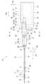
図1及び図2に示されるカテーテル10は、粥腫切除用であり、図1及び図2に示されるように、シャフト11(第1シャフトの一例)と、シャフト11の内部空間26、27に設けられたカッター21及びシャフト22(第2シャフトの一例)と、シャフト11の基端と連結されたハブ14と、シャフト11の基端部80に設けられたレバー81及びジョイント82と、カッター21に回転駆動を付与するモータユニット15とを備える。[Overall Configuration of Catheter 10]
The
[シャフト11]
図2に示されるように、シャフト11は、内部空間26にカッター21を内包できるチューブであり、円筒形状である。シャフト11は、本体部16と先端部13とに大別される。[Shaft 11]
As shown in FIG. 2, the
シャフト11の先端(先端部13の先端)及びシャフト11の基端(本体部16の基端)はそれぞれ開口している。シャフト11の外径は、挿入すべき血管、例えば冠状動脈の内径に応じて設定されている。シャフト11の内径は、カッター21の外径に応じて設定されている。シャフト11の外径及び内径は、シャフト11の軸線方向101に亘ってほぼ均等である。シャフト11の軸線方向101の長さは、ヒトの四肢などのカテーテル挿入部から患部までの長さを考慮して設定されている。 The distal end of the shaft 11 (the distal end of the distal end portion 13) and the proximal end of the shaft 11 (the proximal end of the main body portion 16) are respectively open. The outer diameter of the
本体部16は、例えば合成樹脂製の円管であり、血管の湾曲形状に応じて弾性的に湾曲する。 The
先端部13は、中間部17と、ブレードチューブ31と、縮径部32と、先端チップ33とを備える。
中間部17は、ステンレス製の円管である。中間部17は、本体部16の先端に外側から嵌め込まれている。中間部17の内径は、本体部16の外径と同等程度である。中間部17の内部空間27は、本体部16の内部空間26と連通している。 The
中間部17の周壁25(側壁の一例)の一部には開口20が形成されている。開口20は、周壁25の一部が切欠されることにより形成されている。開口20は、中間部17の周壁25において、所定の周方向102の位置を向いている。開口20には、血管の内壁の一部に形成された粥腫51(図9参照)が挿入される。開口20の形状や大きさは、患部に形成されているであろう粥腫51の形状や大きさを考慮して設定されている。 An
ブレードチューブ31は、両側が開口した円管である。ブレードチューブ31は、中間部17の先端に外側から嵌め込まれている。ブレードチューブ31の内径は、中間部17の外径と同等程度である。ブレードチューブ31の外径及び内径は、軸線方向101に渡ってほぼ均等である。ブレードチューブ31の内部空間28は、中間部17の内部空間27と連通している。 The
図1及び図3に示されるように、ブレードチューブ31は、芯材34により補強されている。芯材34は、ブレードチューブ31の周壁内に埋め込まれている。芯材34は、医療用ステンレスなどの線材が網目に組まれて筒形状にされたものである。なお、図2、図9、及び図10においては、芯材34の図示が省略されている。 As shown in FIGS. 1 and 3, the
図2に示されるように、縮径部32は、両側が開口してテーパ形状に外径が縮径した円管である。縮径部32は、ブレードチューブ31の先端に接続されている。縮径部32の内部空間29は、ブレードチューブ31の内部空間28と連通している。縮径部32は、ポリアミドやポリエーテルアミドなどの弾性変形可能な軟質プラスチックからなる。縮径部32の基端側の内径は、ブレードチューブ31の先端の外径と同程度である。縮径部32は、ブレードチューブ31の先端に外側から嵌め込まれて熱溶着されている。縮径部32の先端側の内径は、先端チップ33の中央部分の外径と同程度である。縮径部32の先端側においては、肉厚が先端側に向かって薄くなっている。 As shown in FIG. 2, the reduced-
先端チップ33は、両側が開口しており、基端36側がテーパ形状に外径が拡がった円管である。先端チップ33は、縮径部32の先端に接続されている。先端チップ33の内部空間30は、ブレードチューブ31の内部空間28と連通している。先端チップ33の先端35側は、縮径部32の先端から軸線方向101の外側へ突出している。先端チップ33の基端36側は、縮径部32の内部空間29を軸線方向101に延出している。基端36は、ブレードチューブ31の内部空間28に至っている。つまり、ブレードチューブ31の先端側部分から縮径部32においては、ブレードチューブ31及び縮径部32を外側とし、先端チップ33を内側とした二重管構造となっている。 The
先端チップ33は、基端36側において拡径されているが、その他の部分の外径及び内径はほぼ均等である。均等な部分の外径は、ブレードチューブ31の内径より小さく、縮径部32の先端の内径と同程度である。また、基端36側は拡径されているが、その最大径は、ブレードチューブ31の内径より小さい。 The
先端チップ33は、ポリアミドやポリエーテルアミドなどの弾性変形可能な軟質プラスチックからなる。先端チップ33は、縮径部32の先端に挿入されて熱溶着されている。 The
[カッター21]
図2に示されるように、シャフト11の内部空間における開口20の近傍(詳細には、中間部17の内部空間27から、本体部16の内部空間26のうち中間部17近傍に位置する部分までに亘る空間)には、カッター21が設けられている。カッター21は、概ね円筒形状である。カッター21の外径は、シャフト11の内径より若干小さい。カッター21の先端側には、複数の刃が中心から放射状に延びるように形成されている。図2には現れていないが、カッター21の中心には、軸線方向101に沿って貫通孔が形成されている。[Cutter 21]
As shown in FIG. 2, the vicinity of the
[バルーン23]
図1及び図2に示されるように、シャフト11の軸線に対して開口20と反対側となる位置には、バルーン23が設けられている。バルーン23は、中間部17の周壁25からシャフト11の径方向外側へ膨らむことが可能なものである。バルーン23は、カテーテル10が血管に挿入されるまでの間、折り畳まれて中間部17の周壁25に密着している。バルーン23の素材としては、生体適合性を有する材料が好ましく、具体的には、ポリウレタン、ポリエチレン、ポリエステル、ポリプロピレン、ポリアミド、ポリアミドエラストマー、ポリテトラフルオロエチレン、ポリフッ化ビニリデン等が挙げられる。[Balloon 23]
As shown in FIGS. 1 and 2, a
図2に示されるように、バルーン23の基端側は、中間部17の周壁25から本体部16の周壁に沿って設けられたバルーン用管体24に接続されている。バルーン用管体24の内部空間は、バルーン23の内部空間と連通している。バルーン用管体24は、ハブ14(図1参照)まで延出されている。バルーン用管体24の内部空間は、ハブ14のポート41と接続されている。ハブ14のポート41から注入された生理食塩水などの液体がバルーン23内に流入することによって、血管内においてバルーン23が膨らまされる。バルーン用管体24は、ポリアミド、ポリアミドエラストマー、ポリエーテルアミドなどの弾性変形可能な軟質プラスチックの成形体である。 As shown in FIG. 2 , the proximal end of the
[シャフト22]
図2に示されるように、カッター21の基端に、シャフト22が連結されている。シャフト22は細長な管である。シャフト22の内部空間は、カッター21の貫通孔と連通している。シャフト22の内部空間及びカッター21の貫通孔には、ガイドワイヤが挿通される。[Shaft 22]
As shown in FIG. 2, a
図1及び図2に示されるように、シャフト22の一端(シャフト22の先端部88)は、カッター21の基端に連結されている。シャフト22は、内部空間26、27を、カッター21の基端からシャフト11の基端へ向けてシャフト11の軸線方向101に沿って延出されている。つまり、シャフト11の軸線方向101は、シャフト22の軸線方向でもある。図1及び図3に示されるように、シャフト22は、シャフト11の基端から突出して更に延びた基端部80を有している。 As shown in FIGS. 1 and 2 , one end of shaft 22 (
[ハブ14]
図1及び図3に示されるハブ14は、ポリプロピレンやABSなどの樹脂の成形体である。ハブ14は、シャフト11を血管へ挿抜するときなどの操作において持ち手となり得る。[Hub 14]
The
図1及び図3に示されるように、ハブ14は、本体42と回転体43とを備える。 As shown in FIGS. 1 and 3, the
回転体43は、シャフト11の基端と連結している。回転体43は、本体42によってシャフト11の軸周りに回転可能、つまり周方向102に回転可能に支持されている。シャフト11及び回転体43は、一体に回転可能である。回転体43が把持されて回転操作されることによって、シャフト11が軸周りに回転する。つまり、ハブ14は、シャフト11を回転可能に支持している。 The rotating
回転体43は、先端(図1の左向き)へ向かって外径が徐々に小さくなるテーパ形状である。回転体43の周面47には、概ね軸線方向101に沿って延びた突条46が形成されている。突条46は、周方向102に間隔を空けて複数形成されている。突条46は、回転体43の周面47から径方向へ突出しており、ほぼ軸線方向101へ沿って延びている。隣り合う2つの突条46の間には、凹部が形成されている。つまり、回転体43の周面47には、凹凸が形成されている。なお、回転体43の周面47に、凹凸が形成されていなくてもよい。 The rotating
本体42は、回転体43と連結されたシャフト11の内部空間26と連続する内部空間を有する円筒形状である。シャフト22の基端部80が、本体42の内部空間を貫通している。本体42は、シャフト22の基端部80を軸周りに回転可能(周方向102に回転可能)且つ軸線方向101に沿って移動可能に支持している。本体42は、シャフト22の軸線方向101の移動を所定範囲に制限するストッパ(不図示)を備えている。 The
本体42は、基端側に、基端へ向かうにしたがって外径が徐々に小さくなる縮径部44を備える。縮径部44の基端の外径は、円筒体76の内径よりも小さい。したがって、縮径部44の基端は、円筒体76の内部空間に挿入されて、円筒体76と嵌合可能である。 The
本体42は、軸線方向101に対して交差する方向へ延出したポート41を備える。ポート41にシリンジなどの他のデバイスが接続される。他のデバイスから流出入される生理食塩水などの流体が、ハブ14からバルーン用管体24へ流出入する。なお、本体42には、シャフト11の本体部16の内部空間26と連続する他のポートが設けられていてもよい。このようなポートは、例えば、シャフト11の内部に進入した切除済みの粥腫を回収する目的などに用いられる。 The
本体42の基端側の開口45から、本体42の内部空間を貫通したシャフト22の基端部80が延出している。 A
なお、本実施形態では、ハブ14は筐体74における円筒体76と接続されているが、ハブ14は筐体74における円筒体76以外の部分と接続されていてもよい。例えば、ハブ14は、円筒体76と間隔を空けて軸線方向101に沿って並んで配置された状態で、筐体74からハブ14へ向けて延出された支持部(不図示)によって支持されていてもよい。 Although the
[レバー81及びジョイント82]
図3に示されるように、レバー81及びジョイント82が、基端部80における本体42の開口45から延出した部分に取り付けられている。[
As shown in FIG. 3, a
ジョイント82は、筒形状の部材である。ジョイント82は、シャフト22の基端の外側に嵌め込まれて、圧入や接着等によってシャフト22に固定されている。これにより、ジョイント82は、シャフト22と一体に回転可能である。 The joint 82 is a cylindrical member. The joint 82 is fitted to the outside of the proximal end of the
ジョイント82の周面には、軸線方向101に沿って延びた突条83が形成されている。突条83は、周方向102に間隔を空けて複数(本実施形態では4本)形成されている。 A
レバー81は、シャフト22におけるハブ14とジョイント82の間に設けられている。図4に示されるように、レバー81は、貫通孔84を有している。図3及び図7に示されるように、シャフト22が貫通孔84を貫通している。これにより、レバー81は、シャフト22によって回転可能に支持されている。
図5に示されるように、シャフト22におけるハブ14とジョイント82の間には、段差85が形成されている。ハブ14とジョイント82の間に位置するシャフト22における段差85よりハブ14側の第1部分91の外径は、貫通孔84の内径より大きい。ハブ14とジョイント82の間に位置するシャフト22における段差85よりジョイント82側の第2部分92の外径は、第1部分91の外径より小さく、且つ貫通孔84の内径より小さい。ジョイント82の外径は、貫通孔84の内径より大きい。ジョイント82から露出した第2部分92の軸線方向101に沿った長さ、換言すると段差85とジョイント82との間のシャフト22の軸線方向101に沿った長さは、レバー81の貫通孔84が形成されている部分の軸線方向101の長さと同一である。第2部分92は、貫通孔84に挿通されている。レバー81は、段差85とジョイント82とに挟まれている。これにより、レバー81は、シャフト22に対して軸線方向101に沿って移動せず、且つシャフト22の軸線方向101周りに回転可能である。 As shown in FIG. 5, a
図4に示されるように、レバー81は、基端部86と先端部87とを備える。基端部86は、貫通孔84周りの大部分が円筒形状であって、基端部86の一部分が、貫通孔84の径方向へ延出している。基端部86の一部分の延出端は、先端部87と連続している。基端部86の一部分は、先端部87へ近づくにしたがって貫通孔84の周方向102に沿った寸法が徐々に小さくなっている。つまり、基端部86の一部分は、先細りに延出している。先端部87は、基端部86の一部分の延出端よりも周方向102の両側へ突出している。基端部86の一部分の径方向に沿った寸法は、図6に示される円筒体76の内部空間78の幅方向106に沿った寸法よりも小さい。したがって、基端部86の一部分は、内部空間78に挿通可能である。先端部87の基端部86側の面871に、切り込み873が形成されている。なお、切り込み873は、先端部87の基端部86側の面872に形成されていてもよい。 As shown in FIG. 4,
[モータユニット15]
図1に示されるように、ハブ14及びジョイント82は、モータユニット15に接続可能である。モータユニット15は、モータ73と、筐体74とを備える。[Motor unit 15]
As shown in FIG. 1,
筐体74は、本体75と、本体75と一体に形成された円筒体76(筒部の一例)とで構成されている。以下の説明において、図1及び図6に示されるように、本体75の長手方向104、短手方向105、及び幅方向106が定義される。長手方向104、短手方向105、及び幅方向106は、互いに直交している。 The
本体75は、全体として、幅方向106に沿った寸法が短く、長手方向104及び短手方向105それぞれに沿った寸法が幅方向106に沿った寸法よりも長い細長の直方体形状である。また、本体75の長手方向104に沿った寸法は、本体75の短手方向105に沿った寸法よりも長い。 The
本体75は、内部空間を有している。当該内部空間にモータ73や、モータ73に給電するためのバッテリー(不図示)等が配置されている。モータ73は、駆動のオンオフを切り換えるためのスイッチ56と、駆動時に回転する長手方向104に沿った軸周りに回転する回転軸部60とを備える。 The
モータ73は、モータ73を制御するための制御部によって、フィードバック制御されている。なお、制御部は、モータ73に内蔵されている又は本体75の内部空間に配置されている。フィードバック制御では、モータ73の回転軸部60の回転速度に基づいて、モータ73へ供給する電流の大きさが制御される。モータ73は、ヒューズ(不図示)を備えている。フィードバック制御において、モータ73へ供給される電流の大きさが所定値を越えると、ヒューズが切れて、モータ73の駆動が停止する。 The motor 73 is feedback-controlled by a control section for controlling the motor 73 . The controller is built in the motor 73 or arranged in the internal space of the
図1及び図6に示されるように、面79に、開口53が形成されている。面79は、本体75の長手方向104の一端部に位置しており、短手方向105及び幅方向106に拡がっている。図1に示されるように、モータ73のスイッチ56が、開口53を通じて外部に露出している。なお、図6~図8では、スイッチ56の図示が省略されている。 As shown in FIGS. 1 and 6, the
図1に示されるように、面79の短手方向105の一端部から延びる面57に、凹凸が形成されている。面57は、長手方向104及び幅方向106に拡がっている。凹凸は、3つの凹部58と、隣り合う2つの凹部58の間にある凸部とで形成されている。凹部58は、長手方向104に並んで形成されている。各凹部58は幅方向106に延びている。なお、面57に、上記のような凹凸が形成されていなくてもよい。 As shown in FIG. 1, the
円筒体76は、本体75の長手方向104の一端部に設けられている。円筒体76は、面79の短手方向105の他端から延びる面59に設けられている。面59は、長手方向104及び幅方向106に拡がっている。円筒体76の内部空間78の内径は、レバー81の基端部86の外径よりも大きい。したがって、基端部86は、円筒体76の内部空間78に挿入可能である。 The
円筒体76は、長手方向104(所定方向の一例)に沿って延びている。図6に示されるように、円筒体76の内部空間78は、開口77を通じて筐体74の外部と連通している。開口77は、円筒体76の周面に長手方向104に沿って延びている。円筒体76の周面は、筐体74の外面の一部である。 The
図6に示されるように、円筒体76の周面における開口77の幅方向106の両側に、径方向外向きへ突出する凸部63、64が形成されている。凸部63、64の先端面631、641は、円筒体76の周面と平行な曲面である。 As shown in FIG. 6 ,
図1に示されるように、円筒体76の軸方向の両側は開口しており、先端側つまり側壁66に開口54が位置しており、基端側つまり側壁67に開口55が位置している。開口77と開口54とは連続している。本体75の内部空間における開口55の近傍には、モータ73の回転軸部60が位置する。回転軸部60は、長手方向104に沿った穴61を有しており、穴61は開口55と連続している。ジョイント82は、開口55を通じて穴61に挿入される。これにより、ジョイント82に、モータ73の回転が伝達される。 As shown in FIG. 1 , the
図6に示されるように、穴61の内周面には、突条62が形成されている。突条62は、長手方向104に沿って延びている。突条62は、周方向102に間隔を空けて複数(本実施形態では4本)形成されている。 As shown in FIG. 6 , a
図1に示されるように、ハブ14の縮径部44が、開口54を通じて内部空間78へ挿入可能である。縮径部44の先端側の外径は開口54の内径よりも小さく、縮径部44の基端側の外径は開口54の内径よりも大きい。縮径部44は、開口54に挿入されることによって円筒体76に嵌合される。 As shown in FIG. 1, the reduced
ハブ14が円筒体76と嵌合した接続状態(図1に示される状態)において、図7に示されるように、レバー81の基端部86は、円筒体76の内部空間78に挿入されており、基端部86の一部分(径方向外向きへ延出する部分)が、開口77を通じて円筒体76の外部へ突出している。レバー81の先端部87は、円筒体76の外部に位置する。 In the connected state (the state shown in FIG. 1) in which the
図1に示されるように、レバー81は、シャフト22と一体に軸線方向101に沿って移動する。つまり、レバー81が軸線方向101に沿って移動すると、シャフト22も軸線方向101に沿って移動する。レバー81が軸線方向101に沿って所定範囲移動されても、レバー81が開口54、55に到達することはない。レバー81は、基端部86が内部空間78に位置しつつ、軸線方向101に沿って所定範囲内で移動可能である。 As shown in FIG. 1,
図7に示されるように、レバー81の先端部87は、幅方向106において、開口77の開口寸法よりも長い。接続状態において、レバー81の先端部87は、開口77の縁部である凸部63、64を覆っている。つまり、先端部87は、開口77において対向する縁部の両方を覆っている。先端部87が凸部63、64を覆うとは、先端部87が凸部63、64よりも外側に位置して凸部63、64の少なくとも一部分を覆っている状態をいい、先端部87が凸部63、64の全てを覆うことを要するものではない。 As shown in FIG. 7 , the
接続状態において、レバー81の先端部87の基端部86側の面871、872と、円筒体76の凸部63、64の先端面631、641とは、隙間65を空けて対向している。本実施形態では、基端部86の貫通孔84の軸線とシャフト22の軸線とが合致する状態における隙間65の寸法G1は、貫通孔84の内径とシャフト22(貫通孔84に挿入されている部分)の外径との寸法差G2より大きい。なお、レバー81が、重力によって下方へ移動して、貫通孔84の内面がシャフト22に当接した状態において(例えば、図8(A)参照)、隙間65は、寸法G1から寸法差G2を差し引いた寸法となる。 In the connected state, the
なお、寸法G1と寸法差G2とは同一であってもよい。この場合、図8(B)に示されるように、レバー81が重力によって下方へ移動して、貫通孔84の内面がシャフト22に当接した状態において、レバー81の面871は凸部63の先端面631と当接し、レバー81の面872は凸部64の先端面641と当接する。つまり、レバー81と円筒体76とが当接して、隙間65が無くなる。 Note that the dimension G1 and the dimension difference G2 may be the same. In this case, as shown in FIG. 8B, when the
また、寸法G1は、寸法差G2より小さくてもよい。この場合、レバー81が重力によって下方へ移動して、レバー81と円筒体76とが当接した状態において、貫通孔84の内面68とシャフト22とは離間している。 Also, the dimension G1 may be smaller than the dimension difference G2. In this case, the
[カテーテル10の使用方法]
以下、図8~図10などが参照されつつカテーテル10の使用方法が説明される。[How to use the catheter 10]
A method of using the
カテーテル10は、血管50の内壁に形成された粥腫51を切除する際に用いられる。カテーテル10は、バルーン23が収縮された状態(図1及び図2参照)で、先端部13から血管50へ挿入される。図9及び図10には示されていないが、カテーテル10を血管50に挿入するに際して、予めガイドワイヤが血管50に挿入される。ガイドワイヤの血管50への挿入は、公知の手法により行われる。血管50に挿入されたガイドワイヤは、先端チップ33から、シャフト11の内部空間、カッター21の貫通孔、シャフト22の内部空間へ順に挿入される。その後、カテーテル10が先端部13から血管50へ挿入される。
冠状動脈のように、血管50が湾曲した箇所において、先端部13は、ガイドワイヤに沿って弾性的に湾曲しながら血管50の粥腫51まで進められる。先端部13が粥腫51に到達し、シャフト11の開口20が粥腫51と対向すると、シャフト11の血管50への挿入が終了される。その後、ガイドワイヤがカテーテル10のハブ14側から引き抜かれる。なお、カテーテル10が血管50に挿入される際に、カテーテル10は、モータユニット15に接続されていても接続されていなくてもよい。 Where the
カテーテル10がモータユニット15に接続される。具体的には、シャフト22の基端部80が、ジョイント82を先頭として、円筒体76の開口54から内部空間78へ挿入される。基端部80が内部空間78の奥へ挿入されると、ジョイント82が開口55を通じてモータ73の回転軸部60と接続される。また、ハブ14が円筒体76に嵌合される。また、レバー81は、基端部86が円筒体76の内部空間78に位置して、一部分が開口77を通じて外部へ突出し、先端部87が円筒体76の外部に位置する。これにより、カテーテル10とモータユニット15とが、接続状態となる。
図9に示されるように、粥腫51にシャフト11の開口20が対向した状態において、ポート41からバルーン用管体24へ流入された流体により、収縮状態のバルーン23が拡張される。拡張されたバルーン23が、粥腫51と反対側の血管50の内壁に当接することによって、開口20が粥腫51に密着され、粥腫51の一部が開口20からシャフト11の内部空間へ進入した状態で、カテーテル10が血管50に対して固定される。 As shown in FIG. 9 , with the
操作者は、モータユニット15を把持する。このとき、操作者の親指がレバー81の先端部87に触れ、操作者の他の4本の指のうちの3本がそれぞれ凹部58に嵌った状態となるように、モータユニット15が把持される。 The operator holds the
操作者の人差し指などによって、スイッチ56が押されることによって、モータ73が駆動され、回転軸部60が回転する。すると、図6に示されるように、突条62が周方向102に移動して、ジョイント82の突条83に当接して押す。これにより、ジョイント82が回転する。つまり、回転軸部60を通じてモータ73の回転がジョイント82に伝達される。これにより、シャフト22がジョイント82と一体に回転して、カッター21が回転する。つまり、モータ73は、接続されたジョイント82を介してシャフト22へ軸周りに回転させる駆動力を伝達する。 When the
操作者は、レバー81を、例えば親指によって軸線方向101に沿ってスライドさせる。これにより、シャフト22は、レバー81と一体に軸線方向101に沿ってスライドする。ハブ14が筐体74に接続されており、シャフト11がハブ14に連結されているため、ハブ14、筐体74、及びシャフト11は、レバー81及びシャフト22に追随して軸線方向101へ移動することはない。つまり、レバー81及びシャフト22は、ハブ14、筐体74、及びシャフト11に対して軸線方向101に沿って相対移動する。また、シャフト22が軸線方向101に移動されることによって、カッター21がシャフト11の内部空間27を軸線方向101へ移動する。 The operator slides the
シャフト22がシャフト11に対して軸線方向101の先端側へ移動されることによって、回転するカッター21が粥腫51に当接し、カッター21によって粥腫51が切除される(図10参照)。切除された粥腫51の欠片52は、シャフト11の内部空間27を通じてブレードチューブ31の内部空間28へ進入する。 By moving the
粥腫51が切除されているとき、カッター21からシャフト22及びレバー81を通じて、レバー81に触れている操作者の親指に振動が伝わる。この振動によって、カッター21が粥腫51に触れているか否か、粥腫51が切除されているか否か、粥腫51の硬さ等を、操作者が推量することができる。 Vibrations are transmitted from the
操作者は、親指に力を入れてレバー81を開口77へ向けて押圧することがある。すると、レバー81が弾性変形して、押圧されたレバー81の面871は、円筒体76の凸部63の先端面631に当接し、また、押圧されたレバー81の面872は、円筒体76の凸部64の先端面641に当接する。つまり、図8(B)に示されるように、貫通孔84を区画する内面68がシャフト22と当接した状態において、先端部87は開口77の縁部である凸部63、64と当接可能である。これにより、レバー81が過度に押圧されて、貫通孔84の内面とシャフト22の外面との間の摩擦が増大して、シャフト22の回転が低下することを防止可能である。 The operator may press the
操作者がレバー81を図8(B)の時計回りに回動させると、凸部63がレバー81の切り込み873に入り込む。これにより、シャフト22の軸線方向101の位置が固定される。なお、凸部63の先端面631が円筒体76と平行な曲面であるため、レバー81の回動時に、当該曲面と切り込み873を区画する面871との接触面積が小さくなる。これにより、凸部63と当該面871との間に作用する摩擦力が小さくなるため、凸部63を切り込み873に円滑に入り込ませることができる。 When the operator rotates the
粥腫51の切除が終了すると、バルーン23が収縮されて、カテーテル10が血管50から引き抜かれて撤収される。 After the removal of the
[本実施形態の作用効果]
操作者によって、シャフト22へ向かってレバー81が押されると、レバー81の先端部87が円筒体76の開口部である筐体74の外面(先端面631、641)に当接する。これにより、レバー81がシャフト22へ向かって移動することが抑制される。その結果、基端部86の貫通孔84の内面68とシャフト22とが当接する圧力が過剰に増大せず、シャフト22の回転数が低下しにくい。そのため、モータ73の回転数を上げるためにモータ73へ供給する電流が増大されることによるヒューズの切断を防止することができる。[Action and effect of the present embodiment]
When the operator pushes the
また、カッター21において生じた振動などがシャフト22の振動となり、シャフト22の振動がレバー81を通じて直接に操作者の指に伝達されるので、操作者が指に伝わる振動などを通じてカッター21の状態を把握しやすい。 Further, the vibration generated in the
また、先端部87が開口77の縁部である凸部63、64と当接可能であることにより、レバー81が周方向102に傾きにくいため、レバー81の姿勢を安定させることができる。 Further, since the
また、本実施形態によれば、シャフト11が軸周りに回転可能にハブ14に支持されているため、回転体43と共にシャフト11を軸周りに回転させることによって、シャフト11の開口20の向きを変えることができる。シャフト11を軸周りに回転させても、モータユニット15の筐体74は回転しないので、筐体74を把持する操作者の手の姿勢を変化させる必要がない。 Further, according to this embodiment, since the
また、回転体43の突条46が把持されることによって、回転体43を安定して回転させることができる。 Moreover, by gripping the
また、筐体74を把持するときに、親指でレバー81を操作しつつ、他の指を凹部58に当てることができる。これにより、筐体74を安定して把持することができる。 Also, when gripping the
また、シャフト22に段差85を設けることによって、シャフト22におけるジョイント82及びハブ14の間において、シャフト22に対して軸線方向101へ移動しないようにレバー81を設けることができる。 Further, by providing the
[変形例]
上記実施形態では、モータユニット15において、シャフト22が挿入され、ハブ14が嵌合される部分は、円筒に構成されていた(円筒体76)。しかし、当該部分は、円筒に限らず、筒状であればよい。例えば、当該部分は、四角筒であってもよい。[Modification]
In the above-described embodiment, the portion of the
上記実施形態では、先端部87は開口77の縁部である凸部63、64と当接可能であった。つまり、先端部87は、両方の縁部と当接可能であった。しかし、先端部87は、凸部63、64の一方とのみ当接可能であってもよい。つまり、先端部87は、片方の縁部とのみ当接可能であってもよい。 In the above embodiment, the
上記実施形態では、ハブ14は、シャフト11を回転可能に支持していたが、シャフト11を回転可能に支持していなくてもよい。例えば、シャフト11は、ハブ14に固定されていてもよい。この場合、ハブ14は、回転体43を備えていない。 Although the
上記実施形態では、モータユニット15の本体75は、全体として細長の直方体形状であったが、このような形状に限らず、レバー81のスライドに支障がないことを条件として任意の形状をとり得る。 In the above-described embodiment, the
上記実施形態では、カテーテル10は、粥腫切除用であった。しかし、カテーテル10は、レバー81をスライドさせることによって、シャフト22を介してレバー81と繋がっているカッター21をスライドさせるものであれば、粥腫切除以外の用途に用いられるものであってもよい。 In the above embodiments,
10 カテーテル
11 シャフト(第1シャフト)
13 先端部
14 ハブ
15 モータユニット
20 開口
21 カッター
22 シャフト(第2シャフト)
25 周壁(側壁)
26 内部空間
27 内部空間
42 本体
43 回転体
47 周面
66 側壁
67 側壁
73 モータ
74 筐体
76 円筒体(筒部)
78 内部空間
81 レバー
82 ジョイント
84 貫通孔
86 基端部
87 先端部
104 長手方向(所定方向)
10
13
25 Surrounding wall (side wall)
26
78
Claims (6)
Translated fromJapanese上記第1シャフトの内部空間における上記第1開口付近に位置するカッターと、
上記内部空間を上記第1シャフトに沿って延びており、一端が上記カッターと連結されており、他端が上記第1シャフトの基端から突出している第2シャフトと、
上記第1シャフトの基端と連結されており、上記第1シャフトの基端から突出した上記第2シャフトが貫通されており、上記第2シャフトを軸周りに回転可能に支持するハブと、
上記第2シャフトの他端に固定されたジョイントと、
上記第2シャフトが挿通された貫通孔を有しており、上記第2シャフトにおける上記ジョイント及び上記ハブの間において、上記第2シャフトに対して上記第2シャフトの軸線方向へ移動しないように設けられたレバーと、
接続された上記ジョイントを介して上記第2シャフトへ軸周りに回転させる駆動力を伝達するモータ、及び上記モータを覆っており上記ハブが接続される筐体を有するモータユニットと、を備え、
上記筐体は、筒部と、当該筒部の側壁を貫通して所定方向へ延びる第2開口と、を有しており、
上記レバーは、
上記ハブが上記筐体と嵌合した接続状態において上記筒部の内部空間から外部へ突出しており、上記貫通孔が形成された基端部と、
上記接続状態において上記筒部の外部において上記基端部と連続しており、上記第2開口の縁部を覆う先端部と、を備え、
上記接続状態において、上記レバーが上記所定方向へスライドされることにより、上記第2シャフトが上記レバーと一体に上記第1シャフトに対して上記軸線方向へスライドし、
上記貫通孔を区画する内面が上記第2シャフトと当接した状態において、上記レバーの先端部は上記第2開口の縁部と当接可能であるカテーテル。a cylindrical first shaft having a first opening in the side wall of the distal end;
a cutter positioned near the first opening in the interior space of the first shaft;
a second shaft extending along the first shaft in the inner space, having one end connected to the cutter and the other end protruding from the proximal end of the first shaft;
a hub connected to the proximal end of the first shaft, penetrated by the second shaft projecting from the proximal end of the first shaft, and supporting the second shaft rotatably around an axis;
a joint fixed to the other end of the second shaft;
It has a through hole through which the second shaft is inserted, and is provided between the joint and the hub in the second shaft so as not to move in the axial direction of the second shaft with respect to the second shaft. and
a motor unit that transmits a driving force for rotating the second shaft around an axis through the connected joint, and a motor unit that includes a housing that covers the motor and is connected to the hub;
The housing has a tubular portion and a second opening extending in a predetermined direction through a side wall of the tubular portion,
The above lever
a base end projecting outward from the inner space of the cylindrical portion in a connected state where the hub is fitted with the housing, and having the through hole formed therein;
a distal end portion that is continuous with the proximal end portion outside the cylindrical portion in the connected state and covers the edge portion of the second opening;
In the connected state, by sliding the lever in the predetermined direction, the second shaft slides integrally with the lever in the axial direction with respect to the first shaft,
A catheter according to claim 1, wherein a tip portion of the lever can abut against an edge portion of the second opening in a state where an inner surface defining the through hole abuts against the second shaft.
上記第2シャフトが貫通された本体と、
上記第1シャフトが連結されており、上記本体によって上記第1シャフトの軸周りに回転可能に支持された回転体と、を備える請求項1または2に記載のカテーテル。The above hub is
a main body through which the second shaft passes;
3. The catheter of claim 1 or 2, further comprising a rotating body connected to the first shaft and supported by the main body to be rotatable around the axis of the first shaft.
上記所定方向は、上記軸線方向と平行である請求項1から4のいずれかに記載のカテーテル。The housing has an elongated shape whose dimension along the axial direction is longer than the dimension along two directions perpendicular to the axial direction,
The catheter according to any one of claims 1 to 4, wherein the predetermined direction is parallel to the axial direction.
上記ジョイント及び上記ハブの間に位置しており、上記貫通孔より大径の第1部分と、
上記第1部分及び上記ジョイントの間に位置しており、上記第1部分よりも小径且つ上記貫通孔より小径であり、上記貫通孔に挿通された第2部分と、を備え、
上記ジョイントは、上記貫通孔より大径であり、
上記第2部分の上記軸線方向に沿った長さは、上記基端部の上記軸線方向に沿った長さと同一である請求項1から5のいずれかに記載のカテーテル。
The second shaft is
a first portion positioned between the joint and the hub and having a larger diameter than the through hole;
a second portion positioned between the first portion and the joint, having a smaller diameter than the first portion and a smaller diameter than the through hole, and inserted through the through hole;
The joint has a larger diameter than the through hole,
6. The catheter of any one of claims 1 to 5, wherein the axial length of the second portion is the same as the axial length of the proximal portion.
Priority Applications (1)
| Application Number | Priority Date | Filing Date | Title |
|---|---|---|---|
| JP2019209311AJP7283360B2 (en) | 2019-11-20 | 2019-11-20 | catheter |
Applications Claiming Priority (1)
| Application Number | Priority Date | Filing Date | Title |
|---|---|---|---|
| JP2019209311AJP7283360B2 (en) | 2019-11-20 | 2019-11-20 | catheter |
Publications (2)
| Publication Number | Publication Date |
|---|---|
| JP2021078814A JP2021078814A (en) | 2021-05-27 |
| JP7283360B2true JP7283360B2 (en) | 2023-05-30 |
Family
ID=75965648
Family Applications (1)
| Application Number | Title | Priority Date | Filing Date |
|---|---|---|---|
| JP2019209311AActiveJP7283360B2 (en) | 2019-11-20 | 2019-11-20 | catheter |
Country Status (1)
| Country | Link |
|---|---|
| JP (1) | JP7283360B2 (en) |
Citations (2)
| Publication number | Priority date | Publication date | Assignee | Title |
|---|---|---|---|---|
| WO2013080730A1 (en) | 2011-11-28 | 2013-06-06 | ニプロ株式会社 | Atherectomy device |
| JP2018023840A (en) | 2011-09-13 | 2018-02-15 | ジョン・ピー・ピゴット | Intravascular catheter having expandable incising portion |
Family Cites Families (2)
| Publication number | Priority date | Publication date | Assignee | Title |
|---|---|---|---|---|
| DE3781826T2 (en)* | 1986-02-28 | 1993-01-07 | Devices Vascular Intervention | MOTOR DRIVE UNIT FOR AN ARTERIEECTOMY CATHETER. |
| WO1990000371A1 (en)* | 1988-07-05 | 1990-01-25 | Devices For Vascular Intervention, Inc. | Atherectomy device and method |
- 2019
- 2019-11-20JPJP2019209311Apatent/JP7283360B2/enactiveActive
Patent Citations (2)
| Publication number | Priority date | Publication date | Assignee | Title |
|---|---|---|---|---|
| JP2018023840A (en) | 2011-09-13 | 2018-02-15 | ジョン・ピー・ピゴット | Intravascular catheter having expandable incising portion |
| WO2013080730A1 (en) | 2011-11-28 | 2013-06-06 | ニプロ株式会社 | Atherectomy device |
Also Published As
| Publication number | Publication date |
|---|---|
| JP2021078814A (en) | 2021-05-27 |
Similar Documents
| Publication | Publication Date | Title |
|---|---|---|
| US10856898B2 (en) | Foreign object removal device | |
| US5921956A (en) | Surgical instrument | |
| JP7019582B2 (en) | Medical device | |
| US12114884B2 (en) | Medical device and treatment method | |
| JP6885923B2 (en) | Systems and methods for operating long medical devices | |
| JP7222978B2 (en) | medical device | |
| JP2019503787A (en) | Medical devices and related methods of use | |
| CN109788970B (en) | Medical instrument | |
| JP7283360B2 (en) | catheter | |
| WO2014162441A1 (en) | Actuating member, and medical device | |
| US10888350B2 (en) | Device handle for a medical device | |
| US11389191B2 (en) | Device handle for a medical device | |
| US11559324B2 (en) | Atherectomy system with supply line fitment | |
| CN111818869B (en) | Medical device | |
| JP5239205B2 (en) | Endoscope hood | |
| JPWO2020105210A1 (en) | Medical device | |
| JP6192951B2 (en) | Actuating member and medical device | |
| KR102863550B1 (en) | Endoscopic stabilization tools and related methods of use | |
| JP7403560B2 (en) | medical device | |
| KR100478009B1 (en) | Atherectomy catheter system with radially expanding cutter blades | |
| JP7346591B2 (en) | medical device | |
| WO2018051893A1 (en) | Medical device | |
| US11812989B2 (en) | Medical device | |
| JP7361200B2 (en) | medical device | |
| KR101212318B1 (en) | Intravascular therapeutic operating apparatus |
Legal Events
| Date | Code | Title | Description |
|---|---|---|---|
| A621 | Written request for application examination | Free format text:JAPANESE INTERMEDIATE CODE: A621 Effective date:20220909 | |
| TRDD | Decision of grant or rejection written | ||
| A977 | Report on retrieval | Free format text:JAPANESE INTERMEDIATE CODE: A971007 Effective date:20230413 | |
| A01 | Written decision to grant a patent or to grant a registration (utility model) | Free format text:JAPANESE INTERMEDIATE CODE: A01 Effective date:20230418 | |
| A61 | First payment of annual fees (during grant procedure) | Free format text:JAPANESE INTERMEDIATE CODE: A61 Effective date:20230501 | |
| R150 | Certificate of patent or registration of utility model | Ref document number:7283360 Country of ref document:JP Free format text:JAPANESE INTERMEDIATE CODE: R150 |