JP7282355B2 - CATHETER AND CATHETER MAKING METHOD - Google Patents
CATHETER AND CATHETER MAKING METHODDownload PDFInfo
- Publication number
- JP7282355B2 JP7282355B2JP2018214915AJP2018214915AJP7282355B2JP 7282355 B2JP7282355 B2JP 7282355B2JP 2018214915 AJP2018214915 AJP 2018214915AJP 2018214915 AJP2018214915 AJP 2018214915AJP 7282355 B2JP7282355 B2JP 7282355B2
- Authority
- JP
- Japan
- Prior art keywords
- catheter
- metal wire
- radiopaque marker
- marker
- ray opaque
- Prior art date
- Legal status (The legal status is an assumption and is not a legal conclusion. Google has not performed a legal analysis and makes no representation as to the accuracy of the status listed.)
- Active
Links
- 238000000034methodMethods0.000titledescription8
- 239000003550markerSubstances0.000claimsdescription87
- 229910052751metalInorganic materials0.000claimsdescription72
- 239000002184metalSubstances0.000claimsdescription72
- 239000011347resinSubstances0.000claimsdescription25
- 229920005989resinPolymers0.000claimsdescription25
- 238000004804windingMethods0.000claimsdescription18
- 238000004519manufacturing processMethods0.000claimsdescription15
- 238000002844meltingMethods0.000claimsdescription12
- 230000008018meltingEffects0.000claimsdescription12
- 230000008439repair processEffects0.000claimsdescription12
- 239000000463materialSubstances0.000claimsdescription11
- 239000011162core materialSubstances0.000claimsdescription10
- 230000002093peripheral effectEffects0.000claimsdescription10
- 230000004927fusionEffects0.000claimsdescription6
- 230000005540biological transmissionEffects0.000claims1
- 239000010410layerSubstances0.000description14
- 238000005520cutting processMethods0.000description4
- 238000012014optical coherence tomographyMethods0.000description4
- 230000003014reinforcing effectEffects0.000description3
- KDLHZDBZIXYQEI-UHFFFAOYSA-NPalladiumChemical compound[Pd]KDLHZDBZIXYQEI-UHFFFAOYSA-N0.000description2
- 239000003814drugSubstances0.000description2
- 229940079593drugDrugs0.000description2
- BASFCYQUMIYNBI-UHFFFAOYSA-NplatinumChemical compound[Pt]BASFCYQUMIYNBI-UHFFFAOYSA-N0.000description2
- 238000005498polishingMethods0.000description2
- 239000000126substanceSubstances0.000description2
- 229910001182Mo alloyInorganic materials0.000description1
- 229910000990Ni alloyInorganic materials0.000description1
- 239000004952PolyamideSubstances0.000description1
- RTAQQCXQSZGOHL-UHFFFAOYSA-NTitaniumChemical compound[Ti]RTAQQCXQSZGOHL-UHFFFAOYSA-N0.000description1
- 229910045601alloyInorganic materials0.000description1
- 239000000956alloySubstances0.000description1
- 230000036772blood pressureEffects0.000description1
- 210000004204blood vesselAnatomy0.000description1
- 229910017052cobaltInorganic materials0.000description1
- 239000010941cobaltSubstances0.000description1
- GUTLYIVDDKVIGB-UHFFFAOYSA-Ncobalt atomChemical compound[Co]GUTLYIVDDKVIGB-UHFFFAOYSA-N0.000description1
- 210000003092coiled bodyAnatomy0.000description1
- 230000000694effectsEffects0.000description1
- 229920002457flexible plasticPolymers0.000description1
- 238000002594fluoroscopyMethods0.000description1
- PCHJSUWPFVWCPO-UHFFFAOYSA-NgoldChemical compound[Au]PCHJSUWPFVWCPO-UHFFFAOYSA-N0.000description1
- 229910052737goldInorganic materials0.000description1
- 239000010931goldSubstances0.000description1
- 239000007769metal materialSubstances0.000description1
- 238000000465mouldingMethods0.000description1
- 239000013307optical fiberSubstances0.000description1
- 229910052763palladiumInorganic materials0.000description1
- 229910052697platinumInorganic materials0.000description1
- 229920002647polyamidePolymers0.000description1
- -1polytetrafluoroethylenePolymers0.000description1
- 229920001343polytetrafluoroethylenePolymers0.000description1
- 239000004810polytetrafluoroethyleneSubstances0.000description1
- 229910052703rhodiumInorganic materials0.000description1
- 239000010948rhodiumSubstances0.000description1
- MHOVAHRLVXNVSD-UHFFFAOYSA-Nrhodium atomChemical compound[Rh]MHOVAHRLVXNVSD-UHFFFAOYSA-N0.000description1
- 239000002356single layerSubstances0.000description1
- 239000010935stainless steelSubstances0.000description1
- 229910001220stainless steelInorganic materials0.000description1
- 238000001356surgical procedureMethods0.000description1
- 229910052715tantalumInorganic materials0.000description1
- GUVRBAGPIYLISA-UHFFFAOYSA-Ntantalum atomChemical compound[Ta]GUVRBAGPIYLISA-UHFFFAOYSA-N0.000description1
- 230000008719thickeningEffects0.000description1
- 229910052719titaniumInorganic materials0.000description1
- 239000010936titaniumSubstances0.000description1
- WFKWXMTUELFFGS-UHFFFAOYSA-NtungstenChemical compound[W]WFKWXMTUELFFGS-UHFFFAOYSA-N0.000description1
- 229910052721tungstenInorganic materials0.000description1
- 239000010937tungstenSubstances0.000description1
- 238000002604ultrasonographyMethods0.000description1
- 230000002792vascularEffects0.000description1
Images


Classifications
- A—HUMAN NECESSITIES
- A61—MEDICAL OR VETERINARY SCIENCE; HYGIENE
- A61M—DEVICES FOR INTRODUCING MEDIA INTO, OR ONTO, THE BODY; DEVICES FOR TRANSDUCING BODY MEDIA OR FOR TAKING MEDIA FROM THE BODY; DEVICES FOR PRODUCING OR ENDING SLEEP OR STUPOR
- A61M25/00—Catheters; Hollow probes
Landscapes
- Health & Medical Sciences (AREA)
- Life Sciences & Earth Sciences (AREA)
- Biophysics (AREA)
- Pulmonology (AREA)
- Engineering & Computer Science (AREA)
- Anesthesiology (AREA)
- Biomedical Technology (AREA)
- Heart & Thoracic Surgery (AREA)
- Hematology (AREA)
- Animal Behavior & Ethology (AREA)
- General Health & Medical Sciences (AREA)
- Public Health (AREA)
- Veterinary Medicine (AREA)
- Media Introduction/Drainage Providing Device (AREA)
Description
Translated fromJapanese本発明は、カテーテル及びカテーテルの作製方法に関する。 The present invention relates to catheters and methods of making catheters.
コイル体からなるカテーテル又は内層ルーメンを形成する樹脂製の筒状部材に金属線をコイル状に巻き付けたカテーテルが種々提案されている。 Various catheters made of a coiled body or catheters in which a metal wire is coiled around a resin tubular member forming an inner layer lumen have been proposed.
例えば、本権利者は、内側樹脂層と、前記内側樹脂層の外周に配置された補強用金属線と、前記補強用金属線の外周に配置された外側樹脂層と、を有するカテーテルについて提案している(特許文献1)。 For example, the right holder proposes a catheter having an inner resin layer, a reinforcing metal wire arranged around the outer circumference of the inner resin layer, and an outer resin layer arranged around the outer circumference of the reinforcing metal wire. (Patent Document 1).
こうしたカテーテルには、手術中にカテーテルを身体内に挿入した場合にカテーテルの位置を確認するために、カテーテルの外周にX線不透過性マーカーを取り付けることがある。しかしながら、補強用金属線の外周側にX線不透過性マーカーを取り付けると、X線不透過性マーカーを取り付けた部分が他の部位と比較して外周径が大きくなってしまうという問題点がある。 Such catheters are sometimes fitted with radiopaque markers around the circumference of the catheter to confirm the position of the catheter when it is inserted into the body during surgery. However, when the X-ray opaque marker is attached to the outer peripheral side of the reinforcing metal wire, there is a problem that the outer diameter of the part where the X-ray opaque marker is attached becomes larger than the other parts. .
カテーテルの一部が太く形成されると、血管等の管腔を進行する際にスムーズに進行しなくなる可能性があった。 If a part of the catheter is formed thick, there is a possibility that the catheter may not advance smoothly when advancing through a lumen such as a blood vessel.
そこで、本発明は、上記課題を鑑みてなされたものであり、金属線が巻回されているカテーテルに対してX線不透過性マーカーを取り付けた場合であっても外周径が太くなることのないカテーテルを提供することを目的とする。 Therefore, the present invention has been made in view of the above problems, and is intended to prevent the outer diameter from increasing even when an X-ray opaque marker is attached to a catheter wound with a metal wire. It aims to provide a catheter that does not
本発明は、上述の目的を達成するために以下の手段を採った。 The present invention employs the following means to achieve the above objects.
本発明のカテーテルは、
金属線を巻回することによって形成されたカテーテルにおいて、
前記金属線の一部を溶融して形成された溶融部と、
前記溶融部に形成され、少なくともX線不透過マーカーの厚さよりも深い凹状に形成されたX線不透過マーカー取付部と、
前記X線不透過マーカー取付部に取り付けられた前記X線不透過マーカーと、
を備えていることを特徴とする。The catheter of the present invention is
In a catheter formed by winding a metal wire,
a melted portion formed by melting a portion of the metal wire;
a radiopaque marker mounting portion formed in the fusion zone and formed in a concave shape at least deeper than the thickness of the radiopaque marker;
the radiopaque marker attached to the radiopaque marker mounting portion;
characterized by comprising
本発明にかかるカテーテルによれば、X線不透過マーカーを取り付ける部位がX線不透過マーカーより深い凹状に形成されているのでX線不透過マーカーを取り付けた場合であってもカテーテルの外周が太くなることがなく、X線不透過マーカーを取り付けた部位であっても同じ太さを有するカテーテルとすることができる。また、X線不透過マーカー取付部を作製する部分は金属線を溶融して一体化されているので、凹状に形成しても金属線がほつれることなくX線不透過マーカー取付部を形成することができる。 According to the catheter of the present invention, since the portion where the X-ray opaque marker is attached is formed in a concave shape that is deeper than the X-ray opaque marker, the circumference of the catheter is thick even when the X-ray opaque marker is attached. Therefore, the catheter can be made to have the same thickness even at the site where the X-ray opaque marker is attached. In addition, since the portion where the X-ray opaque marker mounting portion is to be fabricated is integrated by melting the metal wire, the metal wire does not fray even when the concave shape is formed, thereby forming the X-ray opaque marker mounting portion. be able to.
また、本発明にかかるカテーテルにおいて、前記X線不透過マーカー取付部は、前記X線不透過マーカーの断面と同じ断面形状からなる凹状に形成されていることを特徴とするものであってもよい。 Further, in the catheter according to the present invention, the radiopaque marker mounting portion may be formed in a concave shape having the same cross-sectional shape as the cross section of the radiopaque marker. .
X線不透過マーカー取付部の凹状の形態をX線不透過マーカーが丁度入り込む大きさに作製することで、X線不透過マーカーをX線不透過マーカー取付部に取り付けた際に表面が面一になるため、より均一な太さのカテーテルとすることができる。 By making the concave form of the radiopaque marker attachment portion to a size that the radiopaque marker can just fit into, the surface is flush when the radiopaque marker is attached to the radiopaque marker attachment portion. Therefore, a catheter having a more uniform thickness can be obtained.
また、本発明にかかるカテーテルにおいて、前記X線不透過マーカー取付部に取り付けられた前記X線不透過マーカーの周囲を補修材によって、外周面と同一の太さとなるように補修されていることを特徴とするものであってもよい。 Further, in the catheter according to the present invention, the circumference of the radiopaque marker attached to the radiopaque marker attaching portion is repaired with a repair material so as to have the same thickness as the outer peripheral surface. It may be characterized.
補修材で補修することにより、凹状の形態をX線不透過マーカーの断面と同じ形状に作製する必要はなく、X線不透過マーカーより大きな凹状に形成し、X線不透過マーカーを取り付けた後、補修することで周囲の外周面と同一の太さにすることができる。 By repairing with the repair material, it is not necessary to make the concave form the same shape as the cross section of the radiopaque marker, and after forming the concave shape larger than the radiopaque marker and attaching the radiopaque marker , can be repaired to have the same thickness as the surrounding outer peripheral surface.
さらに、本発明にかかるカテーテルにおいて、前記X線不透過マーカーの外周側にさらに金属線が巻回されていることを特徴とするものであってもよい。 Furthermore, in the catheter according to the present invention, a metal wire may be further wound around the outer circumference of the X-ray opaque marker.
外周側にさらに金属線を巻回することによって、外周の太さを均一な太さにすることができる。 By further winding the metal wire around the outer circumference, the thickness of the outer circumference can be made uniform.
さらに、本発明にかかるカテーテルにおいて、巻回された前記金属線の内周側に樹脂製チューブが配置されていることを特徴とするものであってもよい。 Furthermore, in the catheter according to the present invention, a resin tube may be arranged on the inner peripheral side of the wound metal wire.
かかる構成を採用することによって、中央にコアルーメンを有するカテーテルとすることができ、薬剤等を注入したりするのに使用可能なカテーテルとすることができる。 By adopting such a configuration, a catheter having a core lumen in the center can be obtained, and a catheter that can be used for injecting drugs or the like can be obtained.
さらに、本発明にかかるカテーテルにおいて、巻回された前記金属線の内周側にコア材が配置されていることを特徴とするものであってもよい。 Furthermore, in the catheter according to the present invention, a core material may be arranged on the inner peripheral side of the wound metal wire.
かかる構成を採用することによって、例えば、Optical Coherence Tomography(光干渉断層撮影)等に使用するカテーテルとして好適に使用することができる。 By adopting such a configuration, it can be suitably used as a catheter for use in, for example, Optical Coherence Tomography.
また、本発明は、X線不透過マーカーを有するカテーテルを作製する方法において、
金属線が巻回されて形成されたカテーテルの金属線の一部をレーザーによって溶融する溶融工程と、
前記溶融された溶融部を金属加工によりX線不透過マーカーを取り付ける凹状のX線不透過マーカー取付部を作製するX線不透過マーカー取付部作製工程と、
前記X線不透過マーカー取付部にX線不透過マーカーを取り付けるX線不透過マーカー取付工程と、
を含むことを特徴とするカテーテルの作製方法を提供する。The present invention also provides a method of making a catheter having radiopaque markers, comprising:
a melting step of melting a part of the metal wire of the catheter formed by winding the metal wire with a laser;
an X-ray opaque marker attaching portion producing step of producing a concave X-ray opaque marker attaching portion for attaching an X-ray opaque marker by metal processing the melted melted portion;
a radiopaque marker attaching step of attaching a radiopaque marker to the radiopaque marker attachment portion;
A method of making a catheter is provided, comprising:
かかる作製方法を採用することによって、前述した効果を有するカテーテルを作製することができる。 By adopting such a manufacturing method, a catheter having the effects described above can be manufactured.
さらに、本発明にかかるカテーテルの作製方法において、
前記X線不透過マーカー取付工程の後に、
別の金属線を巻回する金属線巻回工程を有することを特徴とするものであってもよい。Furthermore, in the method for fabricating a catheter according to the present invention,
After the radiopaque marker attachment step,
It may be characterized by having a metal wire winding step of winding another metal wire.
さらに、本発明にかかるカテーテルの作製方法において、
前記X線不透過マーカー取付工程の後に、X線不透過マーカーの周囲を補修材で補修する補修工程を有することを特徴とするものであってもよい。Furthermore, in the method for fabricating a catheter according to the present invention,
After the radio-opaque marker mounting step, a repairing step of repairing the periphery of the radio-opaque marker with a repair material may be provided.
さらに、本発明にかかるカテーテルの作製方法において、
前記補修工程の後に、
さらに金属線を巻回する金属線巻回工程を有することを特徴とするものであってもよい。Furthermore, in the method for fabricating a catheter according to the present invention,
After the repair process,
Furthermore, it may be characterized by having a metal wire winding step of winding a metal wire.
本発明にかかるカテーテルによれば、X線不透過マーカーを有するカテーテルにおいてもX線不透過マーカーを有する部位が太くなることのないカテーテルを作製することができる。 According to the catheter according to the present invention, it is possible to manufacture a catheter having radiopaque markers without thickening the region having the radiopaque markers.
以下、本発明にかかるカテーテル100について、図面に沿って詳細に説明する。 The
(第1実施形態)
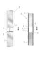
図1は、第1実施形態にかかるカテーテル100を使用したカテーテル器具110の側面概略図であり、図2は、図1のカテーテル100の一部であるA-A部の拡大側面概略図である。(First embodiment)
FIG. 1 is a schematic side view of a
第1実施形態にかかるカテーテル器具110は、図1に示すように、カテーテル100と、その遠位端に先端部50及び近位端側に手元操作部200とを備えている。先端部50及び手元操作部200以外の構成を追加することは適宜行うことができる。先端部50には使用用途に応じて様々な部材が取り付けられる。例えば、血管進行性を向上させるために、柔軟なプラスチック製の先端チップを取り付けたり、血圧を測定するための圧力センサを取り付けたりすることができる。勿論、先端部50の形態については特に限定するものではないし、手元操作部200もどのような形態のものを採用してもよい。 A
カテーテル100は、図1に示すように、主として先端部50を手術領域まで移動させるための部材であり、細長い線状に形成されている。本実施形態にかかるカテーテル100は、図2に示すように、外周が螺旋状又はコイル状に巻回された金属線12で作製されており、中心が中空に形成された筒状に形成されている。第1実施形態においては螺旋状又はコイル状に巻回された金属線12は隙間なく隣接するように巻回されている。金属線12の太さは、特に限定するものではないが、好適には10μm~100μm程度のものを使用するとよい。また、金属線12は、断面が円形のものに限定するものではなく、平線を使用したものであってもよい。金属線12を構成する金属材料の種類は、特に限定するものではない。好適には、例えば、タングステン、タンタル、コバルト、ロジウム、チタン、それらの合金、ステンレス、ニッケル合金またはモリブデン合金等が使用される。 As shown in FIG. 1, the
このようにして金属線12によって作製されたカテーテル100には、X線透視下で容易に位置が確認できるように、任意の位置に1又は2以上のX線不透過マーカー15が取り付けられている。X線不透過マーカー15は、X線による造影が可能な素材、例えば、白金、金又はパラジウム等が使用される。勿論これらに限定するものではない。これらX線不透過マーカー15は、通常、カテーテル100の外周にバンドのように巻きつけて取り付けられる。しかしながら、金属線12の外周に巻きつけると、その部位のみ外周が太くなってしまうという問題がある。カテーテル100の一部が太く形成されると、カテーテル100を身体に導入するときに太くなった部分が管腔に引っかかったりする虞がある。したがって、できる限り太さが均一に形成されることが望ましいのである。そこで、本発明では、図2に示すように、少なくとも取り付けられるX線不透過マーカー15の幅より広い幅で金属線12を溶融して一体化させた溶融部12aを形成し、この溶融部12aをX線不透過マーカー15の厚さ分又はそれ以上の深さとなるように切削や研磨、化学品による溶融等による金属加工よってX線不透過マーカー15の厚さと同じ又はそれより深い凹状に形成されたX線不透過マーカー取付部12bを形成し、このX線不透過マーカー取付部12bにX線不透過マーカー15を巻きつけている。これにより、X線不透過マーカー15が取り付けられた部位のカテーテル100の外周が太くなることがない。X線不透過マーカー取付部12bの凹状の形態は、図2に示すように、X線不透過マーカー15の断面形状と凹状のX線不透過マーカー取付部12bの断面形状とが同一断面となるように作製することが好ましい。このようなX線不透過マーカー取付部12bとすることで、溶融部12aの表面とX線不透過マーカー15の表面とが面一になるため、より均一な太さのカテーテル100を作製することができる。X線不透過マーカー取付部12bの形態は限定するものではなく、図3に示すように、X線不透過マーカー15よりも大きいなだらかなX線不透過マーカー取付部12bを形成してもよい。このようななだらかなX線不透過マーカー取付部12bを形成した場合は、図4に示すように、X線不透過マーカー15によって形成される段差を解消するために、X線不透過マーカー15の周囲を樹脂等の補修材16等でパテ埋めして太さが均一となるように形成するとよい。また、溶融部12aは、少なくとも取り付けられるX線不透過マーカー15の幅よりは広い幅に作製する必要があるが、できる限り幅は狭い方がよい。溶融した部分は湾曲しづらくなるからである。好ましくは、X線不透過マーカー15に対して両側に形成される溶融部の幅は1mm以内に作製するとよい。 One or more X-ray
凹状のX線不透過マーカー取付部12bを作製する際に、金属線12を溶融して一体化した溶融部12aを作製する理由は、カテーテル100を作製する際に金属線12を湾曲させて円筒状に作製しているため、金属線12自体にある程度テンションがかかっている可能性がある。そのため、金属線12の状態のまま切削等により凹状に作製すると、金属線12が切れてほつれてしまう可能性がある。そこで、X線不透過マーカー15が取り付けられる部位及びその近傍を溶融して一体化した溶融部12aを作製することでほつれることを防止するとともに、金属線12のテンションを解消したものである。 The reason why the
上述したカテーテル100は、以下のようにして作製される。
(1)溶融工程
金属線12が巻回されて形成されたカテーテル100の金属線12の一部をレーザーによって溶融し、所定の範囲の金属線12を一体化した溶融部12aを作製する。
(2)X線不透過マーカー取付部作製工程
溶融部12aを切削や研磨、化学品による溶融等によって凹状からなるX線不透過マーカー取付部12bを作製する。
(3)X線不透過マーカー取付工程
凹状に形成されたX線不透過マーカー取付部12bにX線不透過マーカー15を巻きつけるようにして取り付ける。
(4)補修工程
必要に応じて、樹脂等による補修材16によって、X線不透過マーカー15の周囲をパテ埋めするようにして補修し、X線不透過マーカー15を有する部分を前後と同じ太さにする。
こうして、カテーテル100を作製することができる。The
(1) Melting Step A portion of the
(2) X-ray opaque marker mounting portion manufacturing step The X-ray opaque
(3) X-ray opaque marker attachment step The X-ray
(4) Repair process If necessary, a
Thus, the
(第2実施形態)
第2実施形態にかかるカテーテル100aが図5Aに示されている。第2実施形態にかかるカテーテル100aは、第1実施形態にかかるカテーテル100に対してX線不透過マーカー15が取り付けられる前のカテーテル90の金属線12が図5Bに示すように、それぞれ間隔が設けられるように巻回されている点が異なる。(Second embodiment)
A
このようなカテーテル100aの場合は、そのまま金属線12を溶融しても凹部を形成するための溶融部12aを作製することができない。そこで、図5Cに示すように、金属線12を溶融する際にカテーテル100aのコイル状の金属線に一旦両側から圧力をかけてそれぞれの金属線12の間に隙間ができないように密着させた密着部12dの状態にし、この状態で溶融させた後硬化させる。このようにすることで溶融した部分は、第1実施形態と同様の状態の溶融部12aを作製することができる。その後の作製方法は第1実施形態と同様である。 In the case of such a
こうして作製されたカテーテル100aも第1実施形態と同様に切削等により凹状に形成しても金属線12がほつれることがなくX線不透過マーカー取付部12bを作製することができ、X線不透過マーカー15を取り付けた部位が太くなることのないカテーテル100aを作製することができる。 Even if the
(第3実施形態)
第3実施形態に係るカテーテル100bが図6に示されている。第3実施形態にかかるカテーテル100bは、第1実施形態にかかるカテーテル100に対して、さらに外周に別の金属線13が巻回されている点が異なる。その他の構成は第1実施形態と同様であるので、説明を省略する。(Third embodiment)
A
第3実施形態にかかるカテーテル100bは、第1実施形態にかかるカテーテル100の作製方法によって作製された後、別の金属線13をさらに巻回することで金属線巻回工程を付加することで作製される。このようにさらに外周に金属線13を巻回することで、外周表面すべてが金属線13で形成されるので、表面状態が長手方向すべてにおいて太さが変化することがなく、均一性の高いカテーテルとすることができる。 The
また、図2Bに示すようななだらかな凹状からなるX線不透過マーカー取付部12bを形成した場合であっても、補修材16で補修することなく外周から金属線13を巻回することでなめらかな外周表面とすることができる。そのため、補修工程を省略することができる。 Moreover, even when the X-ray opaque
(第4実施形態)
第4実施形態にかかるカテーテル100cが図7に示されている。第4実施形態にかかるカテーテル100cは、第1実施形態にかかるカテーテル100に対し、内層に樹脂製チューブ40が挿入されている点が異なる。その他の点は第1実施形態と同様であるので、説明を省略する。(Fourth embodiment)
A
この第4実施形態にかかるカテーテル100cは、第1実施形態と同様の方法でカテーテル100を作製した後、樹脂製チューブ40を挿入して作製してもよいし、予め樹脂製チューブ40に金属線12を巻回した後、金属を溶融して溶融部12aを作製し、凹状のX線不透過マーカー取付部12bを作製してもよい。 The
内側に樹脂製チューブ40を設けることによって、中心にコアルーメン41が形成される。コアルーメン41は、カテーテル100の使用用途に応じてガイドワイヤ(図示しない。)を通したり、薬液を注入したりするために使用することができる。樹脂製チューブ40の素材は特に限定するものではないが、例えば、ガイドワイヤを通すのに使用される場合であれば、ガイドワイヤとの摺動性が高いポリテトラフルオロエチレン等を使用するとよい。また、樹脂製チューブ40は、必ずしも1層の樹脂層でなくてはならないものではなく、例えば、内周側には薬液や血液等の液体に強い素材を使用し、外周側には周囲に配置される金属線12との密着性や相溶性の高い素材を使用するといったように二層構造に形成してもよい。 A
また、樹脂製チューブ40は、第2実施形態及び第3実施形態と組み合わせて使用してもよい。 Also, the
(第5実施形態)
第5実施形態にかかるカテーテル100dが図8に示されている。第5実施形態にかかるカテーテル100dは、第1実施形態にかかるカテーテル100に対して、外側樹脂層70が形成されている点が異なる。その他の点は第1実施形態と同様であるので説明を省略する。(Fifth embodiment)
A
外側樹脂層70は、カテーテル100dの最外層を構成し、カテーテル100dの内部を保護し金属線12が外部に露出することを防止するとともに、成形時に溶融して金属線12と一体化してこれらの位置を固定する機能を有する。外側樹脂層70の樹脂材料は、特に限定されるものではない。適度な柔軟性を有し、外部を保護可能な樹脂であればよい。好適には、ポリアミド等を使用することができる。 The
このような外側樹脂層70を設けることによって、さらにカテーテル100dの外周面の太さを均一とすることができる。 By providing such an
なお、外側樹脂層70は、第2実施形態~第4実施形態と組み合わせて使用してもよい。 Note that the
(第6実施形態)
第6実施形態にかかるカテーテル100eが図9に示されている。第6実施形態にかかるカテーテル100eは、第1実施形態に対して、内層にコア材80が挿入されている。これ以外の構成は第1実施形態と同様であるので、説明を省略する。(Sixth embodiment)
A
コア材80としては、例えば、ガイドワイヤ、アテレクトミーカテーテルとして使用可能な金属線、Optical Coherence Tomography(光干渉断層撮影)カテーテルに使用される光ファイバー、超音波カテーテルに使用される信号線等が挙げられる。勿論これらに限定されるものではない。 Examples of the
特に、アテレクトミーカテーテルやOptical Coherence Tomography用のカテーテルは、コア材を高速で回転させて使用されるため、より好適に使用することができる。例えば、Optical Coherence Tomography用のカテーテルは、ドライブシャフト95内に挿入されて先端に設けられたレンズ部を高速で回転させつつ撮影する。したがって、従来のように、X線不透過マーカー15等がカテーテルの外周に取り付けられていると、図10Aに示すようにカテーテル100fとドライブシャフト95のルーメンの内壁との間に隙間が形成されることになる。隙間があいているとカテーテル100fが回転した場合に振動が発生したり、先端のレンズ部がぶれたりする可能性がある。そこで、ドライブシャフト95に対してできる限り隙間ができないように形成することが好ましい。本実施形態にかかるカテーテルによれば、図10Bに示すように全長に渡って同一の太さのカテーテル100eとすることができるため、隙間の発生を低減することができ、カテーテル100eが回転した場合の振動を低減でき、先端のレンズ部がぶれたりする可能性を低減することができる。 In particular, atherectomy catheters and optical coherence tomography catheters are used with the core material rotated at high speed, so they can be used more preferably. For example, a catheter for optical coherence tomography is inserted into the
この第6実施形態は、第2実施形態~第3実施形態及び第4実施形態~第5実施形態と組み合わせて使用してもよい。 This sixth embodiment may be used in combination with the second through third and fourth through fifth embodiments.
なお、本発明は上述した各実施形態に何ら限定されることはなく、本発明の技術的範囲
に属する限り種々の態様で実施し得ることはいうまでもない。It goes without saying that the present invention is by no means limited to the above-described embodiments, and can be embodied in various forms as long as they fall within the technical scope of the present invention.
上述した実施の形態で示すように、カテーテルとして使用することができる。 As shown in the embodiments described above, it can be used as a catheter.
12…金属線、12a…溶融部、12b…X線不透過マーカー取付部、12d…密着部、13…金属線、15…X線不透過マーカー、40…樹脂製チューブ、41…コアルーメン、50…先端部、70…外側樹脂層、80…コア材、90…カテーテル、95…ドライブシャフト、100…カテーテル、100a…カテーテル、100b…カテーテル、100c…カテーテル、100d…カテーテル、100e…カテーテル、100f…カテーテル、110…カテーテル器具、200…手元操作部、200e…カテーテル
DESCRIPTION OF
Claims (10)
Translated fromJapanese先端部以外の部分にあるコイル状の前記金属線の一部を、一旦両側から圧力をかけてそれぞれの前記金属線の間に隙間ができないように密着された状態で、少なくとも取り付けられるX線不透過マーカーの幅より広い幅に溶融して形成された溶融部と、
前記溶融部に形成され、少なくともX線不透過マーカーの厚さよりも深い凹状に形成されたX線不透過マーカー取付部と、
前記X線不透過マーカー取付部に取り付けられた前記X線不透過マーカーと、
を備えていることを特徴とするカテーテル。In a catheter formed by winding the metal wiresso that they are spaced apart ,
A portion of the coil-shaped metal wire in a portion other than the tip portion is once pressed from both sides to be in close contact with each other so that no gap is formed between the metal wires. a melted portion formed by melting to a width wider than the width of the transmission marker;
a radiopaque marker mounting portion formed in the fusion zone and formed in a concave shape at least deeper than the thickness of the radiopaque marker;
the radiopaque marker attached to the radiopaque marker mounting portion;
A catheter comprising:
金属線がそれぞれ間隔を有するように巻回されて形成された前記カテーテルの先端部以外の部分にあるコイル状の前記金属線の一部を、一旦両側から圧力をかけてそれぞれの前記金属線の間に隙間ができないように密着された状態で、少なくとも取り付けられるX線不透過マーカーの幅より広い幅に前記金属線の一部をレーザーによって溶融し溶融部を形成する溶融工程と、
溶融された溶融部を金属加工により前記X線不透過マーカーを取り付ける凹状のX線不透過マーカー取付部を作製するX線不透過マーカー取付部作製工程と、
前記X線不透過マーカー取付部に前記X線不透過マーカーを取り付けるX線不透過マーカー取付工程と、
を含むことを特徴とするカテーテルの作製方法。A method of making a catheter having a radiopaque marker comprising:
A portion of the coil-shaped metal wire in a portion other than the distal end portion of the catheter, which is formed by winding the metal wires at intervals, is once pressed from both sides, and each of the metal wires is pulled. a melting step of forming a melted portionby melting a portion of the metal wire with a laser so as to have a width wider than at least the width of the radiopaque marker to be attached while being in close contact with no gap between them ;
an X-ray opaque marker attachment portion producing step of fabricating a concave X-ray opaque marker attachment portion for attaching the X-ray opaque marker by metal processing the melted molten portion;
a radiopaque marker attaching step of attaching the radiopaque marker to the radiopaque marker attachment portion;
A method of making a catheter, comprising:
別の金属線を巻回する金属線巻回工程を有することを特徴とする請求項7に記載のカテーテルの作製方法。After the radiopaque marker attachment step,
8. The method of manufacturing a catheter according to claim 7, further comprising a metal wire winding step of winding another metal wire.
さらに金属線を巻回する金属線巻回工程を有することを特徴とする請求項9に記載のカテーテルの作製方法。After the repair process,
10. The method of manufacturing a catheter according to claim 9, further comprising a step of winding a metal wire.
Priority Applications (2)
| Application Number | Priority Date | Filing Date | Title |
|---|---|---|---|
| JP2018214915AJP7282355B2 (en) | 2018-11-15 | 2018-11-15 | CATHETER AND CATHETER MAKING METHOD |
| PCT/JP2019/034760WO2020100383A1 (en) | 2018-11-15 | 2019-09-04 | Catheter and catheter production method |
Applications Claiming Priority (1)
| Application Number | Priority Date | Filing Date | Title |
|---|---|---|---|
| JP2018214915AJP7282355B2 (en) | 2018-11-15 | 2018-11-15 | CATHETER AND CATHETER MAKING METHOD |
Publications (2)
| Publication Number | Publication Date |
|---|---|
| JP2020080930A JP2020080930A (en) | 2020-06-04 |
| JP7282355B2true JP7282355B2 (en) | 2023-05-29 |
Family
ID=70730403
Family Applications (1)
| Application Number | Title | Priority Date | Filing Date |
|---|---|---|---|
| JP2018214915AActiveJP7282355B2 (en) | 2018-11-15 | 2018-11-15 | CATHETER AND CATHETER MAKING METHOD |
Country Status (2)
| Country | Link |
|---|---|
| JP (1) | JP7282355B2 (en) |
| WO (1) | WO2020100383A1 (en) |
Families Citing this family (10)
| Publication number | Priority date | Publication date | Assignee | Title |
|---|---|---|---|---|
| JP7501082B2 (en)* | 2020-05-01 | 2024-06-18 | 株式会社三洋物産 | Gaming Machines |
| JP7528524B2 (en)* | 2020-05-01 | 2024-08-06 | 株式会社三洋物産 | Gaming Machines |
| JP7528523B2 (en)* | 2020-05-01 | 2024-08-06 | 株式会社三洋物産 | Gaming Machines |
| JP7501081B2 (en)* | 2020-05-01 | 2024-06-18 | 株式会社三洋物産 | Gaming Machines |
| JP7501078B2 (en)* | 2020-05-01 | 2024-06-18 | 株式会社三洋物産 | Gaming Machines |
| JP7501079B2 (en)* | 2020-05-01 | 2024-06-18 | 株式会社三洋物産 | Gaming Machines |
| JP7528525B2 (en)* | 2020-05-01 | 2024-08-06 | 株式会社三洋物産 | Gaming Machines |
| JP7528522B2 (en)* | 2020-05-01 | 2024-08-06 | 株式会社三洋物産 | Gaming Machines |
| JP7501080B2 (en)* | 2020-05-01 | 2024-06-18 | 株式会社三洋物産 | Gaming Machines |
| EP4147739B1 (en)* | 2020-06-12 | 2025-09-03 | TERUMO Kabushiki Kaisha | Catheter |
Citations (7)
| Publication number | Priority date | Publication date | Assignee | Title |
|---|---|---|---|---|
| US5984877A (en) | 1991-02-05 | 1999-11-16 | Fleischhacker, Jr.; Joseph F. | Guide wire marker technique and coil spring marker technique |
| JP2002119599A (en) | 2000-10-18 | 2002-04-23 | Asahi Intecc Co Ltd | Catheter with marker and method of manufacturing the same |
| US20020072729A1 (en) | 2000-12-13 | 2002-06-13 | Hoste John H. | Catheter with enhanced reinforcement |
| JP2015518752A (en) | 2012-05-31 | 2015-07-06 | ベイリス メディカル カンパニー インコーポレイテッドBaylis Medical Company Inc. | Radio frequency punching device |
| US20160114130A1 (en) | 2014-10-24 | 2016-04-28 | Boston Scientific Scimed, Inc. | Medical device including a marker element |
| JP2016179170A (en) | 2015-03-23 | 2016-10-13 | 朝日インテック株式会社 | catheter |
| JP2016189921A (en) | 2015-03-31 | 2016-11-10 | 日本ゼオン株式会社 | Balloon catheter for IABP |
- 2018
- 2018-11-15JPJP2018214915Apatent/JP7282355B2/enactiveActive
- 2019
- 2019-09-04WOPCT/JP2019/034760patent/WO2020100383A1/ennot_activeCeased
Patent Citations (7)
| Publication number | Priority date | Publication date | Assignee | Title |
|---|---|---|---|---|
| US5984877A (en) | 1991-02-05 | 1999-11-16 | Fleischhacker, Jr.; Joseph F. | Guide wire marker technique and coil spring marker technique |
| JP2002119599A (en) | 2000-10-18 | 2002-04-23 | Asahi Intecc Co Ltd | Catheter with marker and method of manufacturing the same |
| US20020072729A1 (en) | 2000-12-13 | 2002-06-13 | Hoste John H. | Catheter with enhanced reinforcement |
| JP2015518752A (en) | 2012-05-31 | 2015-07-06 | ベイリス メディカル カンパニー インコーポレイテッドBaylis Medical Company Inc. | Radio frequency punching device |
| US20160114130A1 (en) | 2014-10-24 | 2016-04-28 | Boston Scientific Scimed, Inc. | Medical device including a marker element |
| JP2016179170A (en) | 2015-03-23 | 2016-10-13 | 朝日インテック株式会社 | catheter |
| JP2016189921A (en) | 2015-03-31 | 2016-11-10 | 日本ゼオン株式会社 | Balloon catheter for IABP |
Also Published As
| Publication number | Publication date |
|---|---|
| WO2020100383A1 (en) | 2020-05-22 |
| JP2020080930A (en) | 2020-06-04 |
Similar Documents
| Publication | Publication Date | Title |
|---|---|---|
| JP7282355B2 (en) | CATHETER AND CATHETER MAKING METHOD | |
| JP7266407B2 (en) | CATHETER AND CATHETER MANUFACTURING METHOD | |
| JP5954748B2 (en) | catheter | |
| JP5688023B2 (en) | catheter | |
| JP5757532B2 (en) | catheter | |
| JP5027651B2 (en) | Vascular catheter | |
| JP7241157B2 (en) | Medical elongate body and medical instrument set | |
| US8986284B2 (en) | Catheter | |
| JP5649131B2 (en) | Medical tube and catheter using the same | |
| JP6426068B2 (en) | Catheter and balloon catheter | |
| US20220054802A1 (en) | Guide wire | |
| JP2012196275A (en) | catheter | |
| JPH08173547A (en) | Guide wire for medical care | |
| US11484687B2 (en) | Catheter | |
| JP2013090717A (en) | Catheter | |
| JP7577999B2 (en) | Support Catheter | |
| JP6879945B2 (en) | catheter | |
| JP7407490B2 (en) | Catheter and catheter manufacturing method | |
| JP6053696B2 (en) | Guide wire | |
| JP6850368B2 (en) | catheter | |
| JP2005323658A (en) | Medical catheter tube and its manufacturing method | |
| CN114173854B (en) | Catheter tube | |
| JP2020182538A (en) | Guide wire | |
| US20120089213A1 (en) | Medical lead with filler layer | |
| JP2024100601A (en) | catheter |
Legal Events
| Date | Code | Title | Description |
|---|---|---|---|
| A621 | Written request for application examination | Free format text:JAPANESE INTERMEDIATE CODE: A621 Effective date:20210831 | |
| A131 | Notification of reasons for refusal | Free format text:JAPANESE INTERMEDIATE CODE: A131 Effective date:20220517 | |
| A521 | Request for written amendment filed | Free format text:JAPANESE INTERMEDIATE CODE: A523 Effective date:20220713 | |
| A131 | Notification of reasons for refusal | Free format text:JAPANESE INTERMEDIATE CODE: A131 Effective date:20221108 | |
| A521 | Request for written amendment filed | Free format text:JAPANESE INTERMEDIATE CODE: A523 Effective date:20230105 | |
| TRDD | Decision of grant or rejection written | ||
| A01 | Written decision to grant a patent or to grant a registration (utility model) | Free format text:JAPANESE INTERMEDIATE CODE: A01 Effective date:20230425 | |
| A61 | First payment of annual fees (during grant procedure) | Free format text:JAPANESE INTERMEDIATE CODE: A61 Effective date:20230510 | |
| R150 | Certificate of patent or registration of utility model | Ref document number:7282355 Country of ref document:JP Free format text:JAPANESE INTERMEDIATE CODE: R150 |