JP7281359B2 - Coil component and its manufacturing method - Google Patents
Coil component and its manufacturing methodDownload PDFInfo
- Publication number
- JP7281359B2 JP7281359B2JP2019140464AJP2019140464AJP7281359B2JP 7281359 B2JP7281359 B2JP 7281359B2JP 2019140464 AJP2019140464 AJP 2019140464AJP 2019140464 AJP2019140464 AJP 2019140464AJP 7281359 B2JP7281359 B2JP 7281359B2
- Authority
- JP
- Japan
- Prior art keywords
- coil component
- precursor
- soft magnetic
- magnetic alloy
- base portion
- Prior art date
- Legal status (The legal status is an assumption and is not a legal conclusion. Google has not performed a legal analysis and makes no representation as to the accuracy of the status listed.)
- Active
Links
- 238000004519manufacturing processMethods0.000titleclaimsdescription24
- 239000002243precursorSubstances0.000claimsdescription111
- 239000002245particleSubstances0.000claimsdescription106
- 229910001004magnetic alloyInorganic materials0.000claimsdescription102
- 239000004020conductorSubstances0.000claimsdescription97
- 239000013078crystalSubstances0.000claimsdescription67
- 239000002159nanocrystalSubstances0.000claimsdescription38
- 238000010438heat treatmentMethods0.000claimsdescription33
- 238000000034methodMethods0.000claimsdescription19
- 229920005989resinPolymers0.000claimsdescription13
- 239000011347resinSubstances0.000claimsdescription13
- 229910052751metalInorganic materials0.000claimsdescription12
- 239000002184metalSubstances0.000claimsdescription10
- 238000001816coolingMethods0.000claimsdescription5
- 229910052742ironInorganic materials0.000claimsdescription5
- 239000000843powderSubstances0.000description30
- 229910045601alloyInorganic materials0.000description12
- 239000000956alloySubstances0.000description12
- 230000000052comparative effectEffects0.000description11
- 230000017525heat dissipationEffects0.000description11
- 239000000463materialSubstances0.000description10
- 238000005259measurementMethods0.000description9
- 238000000465mouldingMethods0.000description9
- 238000002425crystallisationMethods0.000description8
- 230000008025crystallizationEffects0.000description8
- 238000010586diagramMethods0.000description8
- 230000000694effectsEffects0.000description8
- 239000000203mixtureSubstances0.000description8
- 239000011230binding agentSubstances0.000description7
- 229910052709silverInorganic materials0.000description7
- BQCADISMDOOEFD-UHFFFAOYSA-NSilverChemical compound[Ag]BQCADISMDOOEFD-UHFFFAOYSA-N0.000description6
- 150000002739metalsChemical class0.000description6
- 239000004332silverSubstances0.000description6
- 239000011248coating agentSubstances0.000description5
- 238000000576coating methodMethods0.000description5
- 238000010894electron beam technologyMethods0.000description5
- 230000005855radiationEffects0.000description5
- 238000003917TEM imageMethods0.000description4
- 239000000470constituentSubstances0.000description4
- 229910052802copperInorganic materials0.000description4
- 239000010949copperSubstances0.000description4
- 230000006866deteriorationEffects0.000description4
- 239000006249magnetic particleSubstances0.000description4
- 239000002105nanoparticleSubstances0.000description4
- RYGMFSIKBFXOCR-UHFFFAOYSA-NCopperChemical compound[Cu]RYGMFSIKBFXOCR-UHFFFAOYSA-N0.000description3
- 230000005540biological transmissionEffects0.000description3
- 238000009826distributionMethods0.000description3
- 230000006872improvementEffects0.000description3
- 239000012535impuritySubstances0.000description3
- XKRFYHLGVUSROY-UHFFFAOYSA-NArgonChemical compound[Ar]XKRFYHLGVUSROY-UHFFFAOYSA-N0.000description2
- IJGRMHOSHXDMSA-UHFFFAOYSA-NAtomic nitrogenChemical compoundN#NIJGRMHOSHXDMSA-UHFFFAOYSA-N0.000description2
- 229910052782aluminiumInorganic materials0.000description2
- 230000008859changeEffects0.000description2
- 229910052804chromiumInorganic materials0.000description2
- 238000005520cutting processMethods0.000description2
- 239000000696magnetic materialSubstances0.000description2
- 230000035699permeabilityEffects0.000description2
- 229920002037poly(vinyl butyral) polymerPolymers0.000description2
- 238000010298pulverizing processMethods0.000description2
- 230000009467reductionEffects0.000description2
- 239000002002slurrySubstances0.000description2
- 229910052719titaniumInorganic materials0.000description2
- DHKHKXVYLBGOIT-UHFFFAOYSA-N1,1-DiethoxyethaneChemical compoundCCOC(C)OCCDHKHKXVYLBGOIT-UHFFFAOYSA-N0.000description1
- OAYXUHPQHDHDDZ-UHFFFAOYSA-N2-(2-butoxyethoxy)ethanolChemical compoundCCCCOCCOCCOOAYXUHPQHDHDDZ-UHFFFAOYSA-N0.000description1
- 239000004372Polyvinyl alcoholSubstances0.000description1
- 239000011354acetal resinSubstances0.000description1
- PNEYBMLMFCGWSK-UHFFFAOYSA-Naluminium oxideInorganic materials[O-2].[O-2].[O-2].[Al+3].[Al+3]PNEYBMLMFCGWSK-UHFFFAOYSA-N0.000description1
- 229910052786argonInorganic materials0.000description1
- 238000007664blowingMethods0.000description1
- 239000000919ceramicSubstances0.000description1
- 238000013329compoundingMethods0.000description1
- MTHSVFCYNBDYFN-UHFFFAOYSA-Ndiethylene glycolChemical compoundOCCOCCOMTHSVFCYNBDYFN-UHFFFAOYSA-N0.000description1
- 238000010292electrical insulationMethods0.000description1
- 238000002524electron diffraction dataMethods0.000description1
- 238000005516engineering processMethods0.000description1
- 239000003822epoxy resinSubstances0.000description1
- 238000010304firingMethods0.000description1
- 238000005111flow chemistry techniqueMethods0.000description1
- 239000007789gasSubstances0.000description1
- LNEPOXFFQSENCJ-UHFFFAOYSA-NhaloperidolChemical compoundC1CC(O)(C=2C=CC(Cl)=CC=2)CCN1CCCC(=O)C1=CC=C(F)C=C1LNEPOXFFQSENCJ-UHFFFAOYSA-N0.000description1
- 230000020169heat generationEffects0.000description1
- 238000007731hot pressingMethods0.000description1
- 239000004615ingredientSubstances0.000description1
- 238000010884ion-beam techniqueMethods0.000description1
- 238000003475laminationMethods0.000description1
- 238000007561laser diffraction methodMethods0.000description1
- 230000005389magnetismEffects0.000description1
- 230000014759maintenance of locationEffects0.000description1
- 239000011159matrix materialSubstances0.000description1
- 230000010534mechanism of actionEffects0.000description1
- 239000007769metal materialSubstances0.000description1
- 239000002923metal particleSubstances0.000description1
- 239000011812mixed powderSubstances0.000description1
- 238000002156mixingMethods0.000description1
- 229910052759nickelInorganic materials0.000description1
- 229910052757nitrogenInorganic materials0.000description1
- 230000001590oxidative effectEffects0.000description1
- 239000004014plasticizerSubstances0.000description1
- 229920000647polyepoxidePolymers0.000description1
- 229920006324polyoxymethylenePolymers0.000description1
- 229920002451polyvinyl alcoholPolymers0.000description1
- 238000001556precipitationMethods0.000description1
- 230000008569processEffects0.000description1
- 230000001737promoting effectEffects0.000description1
- 239000002994raw materialSubstances0.000description1
- 150000003839saltsChemical class0.000description1
- 238000000790scattering methodMethods0.000description1
- 229920002050silicone resinPolymers0.000description1
- 239000002904solventSubstances0.000description1
- 239000000126substanceSubstances0.000description1
- 230000009466transformationEffects0.000description1
- 229920002554vinyl polymerPolymers0.000description1
- XLYOFNOQVPJJNP-UHFFFAOYSA-NwaterSubstancesOXLYOFNOQVPJJNP-UHFFFAOYSA-N0.000description1
- 229910052726zirconiumInorganic materials0.000description1
Images


Landscapes
- Powder Metallurgy (AREA)
- Soft Magnetic Materials (AREA)
- Manufacturing Cores, Coils, And Magnets (AREA)
- Coils Or Transformers For Communication (AREA)
Description
Translated fromJapanese本発明は、コイル部品及びその製造方法に関する。 The present invention relates to a coil component and its manufacturing method.
近年、携帯用電子機器の多機能化、並びに自動車における電動化及び制御の電子化が進んでいる。そして、こうしたデバイスにおける消費電力低減の要請は、ますます強まっている。これに伴い、搭載されるチップタイプと呼ばれる小型のコイル部品ないしインダクタンス部品には、コアロスの低減及び効率の改善が求められている。このため、コイル部品のコアを構成する磁性材料についても、低損失化のための検討が行われている。 2. Description of the Related Art In recent years, portable electronic devices have become multi-functional, and automobiles have become more electrified and controlled electronically. And the demand for power consumption reduction in such devices is increasing more and more. Along with this, a small coil component or an inductance component called a chip type to be mounted is required to reduce core loss and improve efficiency. For this reason, studies are being conducted to reduce the loss of the magnetic material that constitutes the core of the coil component.
低損失の磁性材料としては、非晶質のマトリックス中にナノサイズの結晶が析出・分散したナノ結晶軟磁性合金が知られている。このナノ結晶軟磁性合金は、十分に結晶化された結晶粒子が均一な大きさで分布しているほど、磁気特性に優れたものとなる。このため、ナノ結晶軟磁性合金製磁心の製造方法として、非晶質粉末をホットプレス等で温度を正確に制御しながら熱処理して、適切なサイズの結晶粒を析出させた後、これを成形する方法(特許文献1)等が採用されている。 As a low-loss magnetic material, a nanocrystalline soft magnetic alloy in which nanosized crystals are precipitated and dispersed in an amorphous matrix is known. This nanocrystalline soft magnetic alloy has better magnetic properties when sufficiently crystallized crystal grains are distributed with a uniform size. For this reason, as a method of manufacturing a nanocrystalline soft magnetic alloy magnetic core, amorphous powder is heat-treated by hot pressing or the like while accurately controlling the temperature, crystal grains of an appropriate size are precipitated, and then formed. A method (Patent Literature 1), etc. is adopted.
しかし、非晶質軟磁性合金粉末を予め結晶化した上で圧粉磁心を製造した場合、成型時の加圧で発生した内部応力を除去できないため、磁気特性が劣化する恐れがあることが知られている(特許文献2)。 However, it is known that when a powder magnetic core is produced after crystallizing amorphous soft magnetic alloy powder in advance, the internal stress generated by the pressurization during molding cannot be removed, and the magnetic properties may deteriorate. (Patent Document 2).
他方、非晶質軟磁性合金粉末を成型後に加熱して結晶化した場合、相変態(結晶析出)に伴う発熱により温度が急上昇して粗大結晶又は不純物相が生成し、磁気特性が劣化することも知られている(特許文献2~5)。 On the other hand, when the amorphous soft magnetic alloy powder is heated and crystallized after molding, the temperature rises rapidly due to the heat generated by the phase transformation (crystal precipitation), and coarse crystals or impurity phases are generated, resulting in deterioration of magnetic properties. are also known (Patent Documents 2 to 5).
そこで、内部応力又は粗大結晶若しくは不純物相による磁気特性の劣化を抑える手段として、下記[1]~[4]のものが報告されている。 Therefore, the following [1] to [4] have been reported as means for suppressing deterioration of magnetic properties due to internal stress, coarse crystals, or impurity phases.
[1]予め加熱した塩浴中に、非晶質軟磁性合金の薄帯を浸漬し、その表面近傍に集中してナノ結晶相を析出させて結晶化度を30%未満とする。次いで、該薄帯を粉砕して得た軟磁性合金粉末をバインダーと混合して造粒粉を作製し、これを金型中でプレス成形した後、追加熱処理して圧粉磁心とする(特許文献2)。[1] A ribbon of an amorphous soft magnetic alloy is immersed in a preheated salt bath, and a nanocrystalline phase is concentrated in the vicinity of the surface of the ribbon to precipitate a crystallinity of less than 30%. Next, the soft magnetic alloy powder obtained by pulverizing the ribbon is mixed with a binder to prepare granulated powder, which is press-molded in a mold and then subjected to additional heat treatment to obtain a powder magnetic core (patent Reference 2).
[2]結晶化開始温度の異なる複数種の軟磁性合金粉末の混合粉を成型し、結晶化開始温度の低い軟磁性合金粉末を選択的に結晶化するように熱処理を行って圧粉磁心とする(特許文献3)。[2] A powder magnetic core is formed by molding a mixed powder of multiple types of soft magnetic alloy powders with different crystallization start temperatures, and performing heat treatment so as to selectively crystallize the soft magnetic alloy powders with a low crystallization start temperature. (Patent Document 3).
[3]構成成分としてSnを含む特定組成の非晶質軟磁性合金の薄帯を粉砕して非晶質軟磁性合金粉末を得た後、該粉末をバインダーと混合して造粒粉を作製し、これを金型中でプレス成形して得た圧粉体を加熱して圧粉磁心とする(特許文献4)。[3] After pulverizing a ribbon of an amorphous soft magnetic alloy having a specific composition containing Sn as a constituent to obtain an amorphous soft magnetic alloy powder, the powder is mixed with a binder to produce granulated powder. Then, this is press-molded in a mold to obtain a powder compact, which is then heated to obtain a powder magnetic core (Patent Document 4).
[4]非晶質軟磁性合金粉末とバインダーとの混合粉末体を加圧成形して得た原料部材を、アルミナ等の放熱性セラミックス粉末に埋設して熱処理を行う(特許文献5)。[4] A raw material member obtained by pressure-molding a powder mixture of an amorphous soft magnetic alloy powder and a binder is embedded in a heat-dissipating ceramic powder such as alumina and then subjected to heat treatment (Patent Document 5).
このように、非晶質軟磁性合金が結晶化する際の温度上昇の抑制によって、粗大結晶又は不純物相の生成を抑制することは可能である。しかし、この場合でも、磁心ないしコイル部品内の位置によってナノ結晶粒子の大きさが相違することが明らかとなった。この相違は、結晶化熱処理の際に、位置によって温度が異なることに起因すると考えられる。すなわち、磁心ないしコイル部品の表面近傍では、非晶質軟磁性合金が結晶化する際に発生する熱は、容易に環境中に放散されるため、温度上昇は小さくなる。これに対し、表面から離れた箇所では、放熱が起こりにくいため、温度上昇は大きくなる。このため、磁心ないしコイル部品の表面から離れた箇所では、結晶粒子の粒径が表面近傍に比べて大きくなるということである。なお、前記[4]の手段によれば、磁心ないしコイル部品の表面近傍からの放熱は促進されるものの、表面から離れた箇所からの放熱への影響は小さいと考えられる。 Thus, it is possible to suppress the generation of coarse crystals or impurity phases by suppressing the temperature rise when the amorphous soft magnetic alloy crystallizes. However, even in this case, it was found that the size of the nanocrystalline particles differs depending on the position within the magnetic core or coil component. This difference is considered to be due to the difference in temperature depending on the position during the heat treatment for crystallization. That is, in the vicinity of the surface of the magnetic core or coil component, the heat generated when the amorphous soft magnetic alloy crystallizes is easily dissipated into the environment, so the temperature rise is small. On the other hand, since heat radiation is less likely to occur at locations distant from the surface, the temperature rise increases. For this reason, the grain size of the crystal grains is larger at locations away from the surface of the magnetic core or coil component than near the surface. It should be noted that although the means [4] promotes heat dissipation from the vicinity of the surface of the magnetic core or coil component, it is considered that the effect on heat dissipation from portions away from the surface is small.
このような磁心ないしコイル部品内の位置による結晶粒子の大きさの相違が低減できれば、さらに高性能のコイル部品、特にコアロスが低減されたコイル部品が得られることが期待される。そこで本発明は、コアロスが低減されたコイル部品を提供することを目的とする。 If such a difference in crystal grain size depending on the position within the magnetic core or coil component can be reduced, it is expected that a coil component with higher performance, particularly a coil component with reduced core loss, can be obtained. SUMMARY OF THE INVENTION Accordingly, an object of the present invention is to provide a coil component with reduced core loss.
本発明者は、前述の目的を達成するために種々の検討を行ったところ、コイル部品の内部に含有される前記ナノ結晶軟磁性合金粒子のうち任意の2粒子についての、該各粒子中に存在するナノ結晶の平均結晶径の差を、該各平均結晶径の50%以下とすることで、前記目的を達成できることを見出し、本発明を完成するに至った。 The present inventor conducted various studies in order to achieve the above-mentioned object, and found that for any two of the nanocrystalline soft magnetic alloy particles contained inside the coil component, in each particle The present inventors have found that the above object can be achieved by setting the difference in average crystal size of existing nanocrystals to 50% or less of each average crystal size, and have completed the present invention.
すなわち、前記課題を解決するための本発明の第1の実施形態は、ナノ結晶軟磁性合金粒子を含む基体部と、該基体部中に配置され、両端部が該基体部の表面に露出する内部導体とを備えたコイル部品であって、前記基体部は、その内部に含有される前記ナノ結晶軟磁性合金粒子のうち任意の2粒子についての、該各粒子中に存在するナノ結晶の平均結晶径の差が、該各平均結晶径の50%以下であることを特徴とするコイル部品である。 That is, the first embodiment of the present invention for solving the above problems is a base portion containing nanocrystalline soft magnetic alloy particles, and a and an inner conductor, wherein the base portion is an average of nanocrystals present in each particle for any two of the nanocrystalline soft magnetic alloy particles contained therein The coil component is characterized in that the difference in crystal diameter is 50% or less of each average crystal diameter.
また、本発明の第2の実施形態は、ナノ結晶軟磁性合金粒子を含む基体部と、該基体部中に配置され、両端部が該基体部の表面に露出する内部導体とを備えたコイル部品の製造方法であって、非晶質軟磁性合金粒子を含む基体部前駆体中に内部導体ないしその前駆体を配置して、該内部導体ないしその前駆体の両端部が表面に露出したコイル部品前駆体を作製すること、及び前記コイル部品前駆体を熱処理して、非晶質軟磁性合金粒子を結晶化してナノ結晶軟磁性合金粒子とすると共に、前記基体部前駆体を基体部とし、前記内部導体の前駆体を内部導体とすることを含むコイル部品の製造方法である。 In addition, a second embodiment of the present invention is a coil comprising a base portion containing nanocrystalline soft magnetic alloy particles, and an inner conductor disposed in the base portion and having both ends exposed to the surface of the base portion. A method for manufacturing a component, wherein an internal conductor or its precursor is placed in a base portion precursor containing amorphous soft magnetic alloy particles, and both ends of the internal conductor or its precursor are exposed to the surface of the coil. preparing a component precursor, heat-treating the coil component precursor to crystallize amorphous soft magnetic alloy particles into nanocrystalline soft magnetic alloy particles, and use the base portion precursor as a base portion; The method for manufacturing a coil component includes using the precursor of the internal conductor as the internal conductor.
さらに、本発明の第3の実施形態は、前述のコイル部品を搭載した回路基板である。 Furthermore, a third embodiment of the present invention is a circuit board on which the coil component described above is mounted.
本発明によれば、コアロスが低減されたコイル部品を提供することができる。 According to the present invention, it is possible to provide a coil component with reduced core loss.
以下、図面を参照しながら、本発明の構成及び作用効果について、技術的思想を交えて説明する。但し、作用機構については推定を含んでおり、その正否は、本発明を制限するものではない。また、以下の実施形態における構成要素のうち、最上位概念を示す独立請求項に記載されていない構成要素については、任意の構成要素として説明される。なお、数値範囲の記載(2つの数値を「~」でつないだ記載)については、下限及び上限として記載された数値をも含む意味である。 Hereinafter, with reference to the drawings, the configuration and effects of the present invention will be described along with technical ideas. However, the mechanism of action is presumed, and whether it is correct or not does not limit the present invention. In addition, among the constituent elements in the following embodiments, constituent elements that are not described in independent claims representing the highest concept will be described as optional constituent elements. It should be noted that the description of a numerical range (a description in which two numerical values are connected by "-") is meant to include numerical values described as lower and upper limits.
[コイル部品]
本発明の第1の実施形態に係るコイル部品(以下、単に「第1実施形態」と記載することがある。)は、ナノ結晶軟磁性合金粒子を含む基体部と、該基体部中に配置され、両端部が該基体部の表面に露出する内部導体とを備える。前記基体部は、その内部に含有される前記ナノ結晶軟磁性合金粒子のうち任意の2粒子についての、該各粒子中に存在するナノ結晶の平均結晶径の差が、該各平均結晶径の50%以下である。ここで、本明細書における基体部の内部とは、基体部中の、表面から50μm以内の領域を除いた部分を意味する。[Coil parts]
A coil component according to a first embodiment of the present invention (hereinafter sometimes simply referred to as "first embodiment") comprises a base portion containing nanocrystalline soft magnetic alloy particles and arranged in the base portion. and an internal conductor having both ends exposed to the surface of the base portion. In the base portion, the difference in the average crystal size of the nanocrystals present in each of the two arbitrary particles of the nanocrystalline soft magnetic alloy particles contained therein is the average crystal size of each of the particles. 50% or less. Here, the inside of the base portion in this specification means a portion of the base portion excluding a region within 50 μm from the surface.
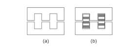
第1実施形態に係るコイル部品11は、図1に示すように、基体部21と、該基体部21中に配置され、両端部311,312が該基体部の表面に露出する内部導体31とを備える。図1には、内部導体31が直線状(棒状)に形成されたコイル部品を示しているが、第1実施形態はこれに限定されず、内部導体がミアンダー状又は平面コイル状に形成されたものでもよく、図2に示すような内部導体31が螺旋状(螺旋の外形を示し、螺旋内部の詳細は図示せず)に形成されたものでもよい。また、図3に示すように、外部電極4が、内部導体31の端部(図示せず)を覆うように形成されたものでもよい。 As shown in FIG. 1, the
基体部21は、ナノ結晶軟磁性合金粒子を含む。これは、本明細書においては、以下のことを意味する。すなわち、基体部の内部に位置する断面200nm×200nmの観察領域について、透過型電子顕微鏡(TEM)により測定した電子線回折パターン(図4参照)において、7.0±0.3[nm-1]の位置にピークが確認されることである。ここで、「ピークが確認される」とは、前記電子線回折パターンにおける7.5nm-1、7.6nm-1、7.7nm-1、7.8nm-1、7.9nm-1及び8.0nm-1の位置における各回折強度の相加平均に対して1.1倍以上の回折強度を示すことをいう。なお、前述の電子線回折パターンの測定領域は、必ずしも個々の単一の軟磁性合金粒子に対応しているとは限らず、該領域に複数の粒子が含まれる場合もあり、また結晶質軟磁性合金粒子や樹脂などのナノ結晶軟磁性合金粒子以外を含む場合がある。しかし、本明細書中では、このような場合についても、前述のピークが確認された場合には、該領域における透過型電子顕微鏡(TEM)により測定した電子線回折パターンを、ナノ結晶軟磁性合金粒子のものと判定する。The
ナノ結晶軟磁性合金の組成は特に限定されないが、高い透磁率が得られる点でFeの含有量が多いものが好ましい。特に、Feの含有量を85質量%以上とすることで、高透磁率が得られる。具体的な組成の例としては、FeSiBNbCu系、FeSiBPCu系、FeSiBC系及びFeSiCrBC系等が挙げられる。 Although the composition of the nanocrystalline soft magnetic alloy is not particularly limited, it is preferable that the content of Fe is large in order to obtain high magnetic permeability. In particular, a high magnetic permeability can be obtained by setting the Fe content to 85% by mass or more. Examples of specific compositions include FeSiBNbCu-based, FeSiBPCu-based, FeSiBC-based, FeSiCrBC-based, and the like.
前記基体部21においては、その内部に含有されるナノ結晶軟磁性合金粒子のうち任意の2粒子について、該各観察領域中に存在するナノ結晶の平均結晶径の差が、該各平均結晶径の50%以下である。すなわち、前記2箇所の観察領域のうち、一方の観察領域中に存在するナノ結晶の平均結晶径(値の小さいもの)をD1、他方の観察領域中に存在するナノ結晶の平均結晶径(値の大きいもの)をD2とした場合に、下記(式1)を満たす。In the

ただし、各観察領域の平均結晶径が等しい場合は、任意にD1及びD2を定める。However, when the average crystal diameter of each observation area is equal,D1 andD2 are determined arbitrarily.
ここで、前記観察領域(ナノ結晶軟磁性合金粒子)内の平均結晶径は、以下の方法で算出する。
まず、前述した観察領域内の電子線回折パターンにおいて、7.0±0.3[nm-1]の位置にピークが確認された領域のTEM像を取得する。次いで、該TEM像を画像処理して、像中に観察されるナノ結晶軟磁性合金粒子中の各結晶の面積を計測し、該面積を有する円の直径である円相当径を各粒子の各結晶について算出する。TEM像における結晶質と、非晶質の各領域については、試料を傾斜させてTEM像を撮像した際に、コントラストが変化する部位が結晶質、変化しない部位が非晶質として見分けることができる。このことから、同一の観察領域において、試料の傾斜を変えて撮像した複数枚の画像、もしくは連続的に試料の傾斜を変化さて撮像された動画を、コントラストの変化に基づき画像処理することで、像中に観察されるナノ結晶軟磁性合金粒子中の各結晶の領域の形や面積を、観測ないし計測できる。次いで、算出された各円相当径の相加平均を算出し、これを当該観察領域(ナノ結晶軟磁性合金粒子)の平均結晶径とする。
この場合、観察領域に結晶質軟磁性合金粒子や樹脂などのナノ結晶軟磁性合金粒子以外のものが含まれていても、算出される平均結晶径は、ナノ結晶軟磁性合金粒子からのみ算出される。また、観察領域に複数のナノ結晶軟磁性合金粒子が含まれていてもよく、算出される平均結晶径は、単一粒子中のナノ結晶のものと同じくその観察領域を代表する平均結晶径であるとする。ただし、観察領域に複数のナノ結晶磁性合金粒子が含まれる場合には、平均結晶径が正確に算出されないことが、ごくまれに起こり得る。これは、粒子間にはナノ結晶が観察されない部分が存在するため、単一粒子のみの場合に比べて円相当径を算出するナノ結晶の数が少なくなることによる。このため、平均結晶径の算出に際しては、観察領域が単一のナノ結晶軟磁性合金粒子中に位置するように調節することが好ましい。Here, the average crystal size in the observation region (nanocrystalline soft magnetic alloy particles) is calculated by the following method.
First, in the electron beam diffraction pattern in the observation region described above, a TEM image of the region where a peak is confirmed at a position of 7.0±0.3 [nm−1 ] is obtained. Next, the TEM image is image-processed, the area of each crystal in the nanocrystalline soft magnetic alloy particles observed in the image is measured, and the equivalent circle diameter, which is the diameter of the circle having the area, is calculated for each particle. Calculate for crystals. Regarding the crystalline and amorphous regions in the TEM image, when the sample is tilted and the TEM image is captured, the regions where the contrast changes are crystalline and the regions where the contrast does not change are distinguishable as amorphous. . For this reason, in the same observation area, by image processing a plurality of images captured by changing the tilt of the sample, or a moving image captured by continuously changing the tilt of the sample, based on the change in contrast, The shape and area of each crystal region in the nanocrystalline soft magnetic alloy particles observed in the image can be observed or measured. Next, the arithmetic mean of the calculated equivalent circle diameters is calculated, and this is taken as the average crystal diameter of the observation region (nanocrystalline soft magnetic alloy particles).
In this case, even if the observation area contains crystalline soft magnetic alloy particles or materials other than nanocrystalline soft magnetic alloy particles such as resin, the calculated average crystal size is calculated only from the nanocrystalline soft magnetic alloy particles. be. In addition, the observation area may contain a plurality of nanocrystalline soft magnetic alloy particles, and the calculated average crystal diameter is the average crystal diameter representative of the observation area, the same as that of nanocrystals in a single particle. Suppose there is However, if the observation area contains a plurality of nanocrystalline magnetic alloy grains, it may very rarely occur that the average crystallite size is not calculated accurately. This is because there are portions where no nanocrystals are observed between the particles, so the number of nanocrystals for calculating the equivalent circle diameter is smaller than in the case of only a single particle. Therefore, when calculating the average crystal size, it is preferable to adjust the observation area so that it is positioned within a single nanocrystalline soft magnetic alloy grain.
ナノ結晶の平均結晶径を比較するナノ結晶軟磁性合金粒子(観察領域)の選び方は任意でよい。しかし、上述したように、基体部の表面近傍とそこから離れた中心部(内部導体近傍)とのナノ結晶の平均結晶径の差が特に大きくなることを鑑みれば、比較対象とするナノ結晶軟磁性合金粒子(観察領域)は、該各箇所から1個ずつ選択することが好ましい。また、前述した理由により、観察領域が単一のナノ結晶軟磁性合金粒子中に位置するように調節されることが好ましい。 Any method may be used to select the nanocrystalline soft magnetic alloy particles (observation regions) for comparing the average crystal diameter of the nanocrystals. However, as described above, the difference in the average crystal diameter of the nanocrystals between the vicinity of the surface of the base portion and the central portion (near the inner conductor) away therefrom becomes particularly large. It is preferable to select one magnetic alloy particle (observation area) from each of the locations. Also, for the reasons mentioned above, it is preferred that the observation region is arranged to lie within a single nanocrystalline soft magnetic alloy grain.
このように、基体部21中の位置によるナノ結晶粒子の平均結晶径の大きさの相違を小さくすることで、コアロスが低減されたコイル部品が得られる。前述したナノ結晶の平均結晶径の差は、該各平均結晶径の40%以下であることが好ましく、30%以下であることがより好ましく、20%以下であることが更に好ましい。 Thus, by reducing the difference in the average crystal diameter of the nanocrystalline particles depending on the position in the
基体部21は、ナノ結晶軟磁性合金粒子に加えて、Fe、Si及びM(ただし、MはFeより酸化しやすい金属元素から選択される少なくとも1種)を必須成分とする結晶質軟磁性合金粒子をさらに含んでもよい。前記Mとしては、Cr、Al、Ti及びZr等が例示される。前記結晶質軟磁性合金粒子はナノ結晶を含有しないため、該粒子を含むことで、ナノ結晶軟磁性合金粒子間のナノ結晶の大きさの違いに起因する特性低下を緩和できる。また、コイル部品のインダクタンスの向上も可能となる。 The
前記結晶質軟磁性合金粒子の含有量は、コイル部品に要求される特性に応じて適宜決定することができる。前述した特性低下の緩和作用が十分に得られる点で、その含有量は、金属磁性粒子全体に対して20体積%以上とすることが好ましく、25体積%以上とすることがよりこのましい。他方、ナノ結晶軟磁性合金粒子による優れた磁気特性を保持する点で、その含有量は、50体積%以下とすることが好ましく、45体積%以下とすることがより好ましい。 The content of the crystalline soft magnetic alloy particles can be appropriately determined according to the properties required for the coil component. The content is preferably 20% by volume or more, more preferably 25% by volume or more, based on the entire metal magnetic particles, in order to sufficiently obtain the effect of alleviating the deterioration of the properties described above. On the other hand, the content is preferably 50% by volume or less, more preferably 45% by volume or less, in order to maintain the excellent magnetic properties of the nanocrystalline soft magnetic alloy particles.
基体部21は、前述したナノ結晶軟磁性合金粒子及びFe、Si及びMを必須成分とする結晶質軟磁性合金粒子等の金属磁性粒子に加えて、樹脂を含んでもよい。基体部21が樹脂を含むことで、その機械的強度が向上する。また、電気的絶縁性も向上する。含有する樹脂としては、金属磁性粒子同士を接着して保形できるものであれば、その種類に制限はなく、エポキシ樹脂やシリコーン樹脂等の各種樹脂が使用できる。また樹脂の含有量も制限されず、例えば軟磁性合金粉100質量部に対して1~10質量部とすることができる。 The
第1実施形態で使用する内部導体31及び外部電極4の材質は、導電性が高く、コイル部品11の使用環境下で物理的及び化学的に安定なものであれば特に限定されず、例えば、銀若しくは銅、又はこれらの合金等が使用できる。また、これらの金属又は合金に被覆を施した被覆導線を使用してもよい。これらの金属又は合金は、熱抵抗が小さい(熱伝導が大きい)点からも好ましい。なぜならば、ナノ結晶粒子の平均結晶径は熱処理によって決まるが、熱抵抗の小さい内部導体の存在によって基体部内部で発生する結晶化熱が放熱されやすくなるため、この結晶径が部分的に大きくなることを抑制できるからである。他方、これらの金属又は合金に施される被覆材料には、相対的に熱抵抗が大きい(熱伝導が小さい)ものが多い。このため、結晶化熱の放熱の点からは、内部導体は、被覆を有さず、かつ基体部に接していることが好ましい。 The material of the
[コイル部品の製造方法]
本発明の第2実施形態に係るコイル部品の製造方法(以下、単に「第2実施形態」と記載することがある。)は、非晶質軟磁性合金粒子を含む基体部前駆体中に内部導体ないしその前駆体を配置して、該内部導体ないしその前駆体の両端部が表面に露出したコイル部品前駆体を作製すること、及び前記コイル部品前駆体を熱処理して、非晶質軟磁性合金粒子を結晶化してナノ結晶軟磁性合金粒子とすると共に、前記基体部前駆体を基体部とし、前記内部導体の前駆体を内部導体とすることを含む。[Manufacturing method of coil component]
A method for manufacturing a coil component according to a second embodiment of the present invention (hereinafter sometimes simply referred to as a “second embodiment”) is a method of manufacturing a coil component in a base portion precursor containing amorphous soft magnetic alloy particles. Arranging a conductor or its precursor to produce a coil component precursor in which both ends of the inner conductor or its precursor are exposed to the surface, and heat-treating the coil component precursor to obtain an amorphous soft magnetism It includes crystallizing the alloy particles to form nanocrystalline soft magnetic alloy particles, using the base portion precursor as the base portion, and using the inner conductor precursor as the inner conductor.
非晶質軟磁性合金粒子としては、FeSiBNbCu系、FeSiBPCu系、FeSiBC系及びFeSiCrBC系等の組成を有するアトマイズ粉、又は薄帯若しくは薄片を粉砕・分級したものが使用できる。非晶質軟磁性合金粒子の粒径は特に限定されず、例えば、体積基準で測定した粒度分布から算出される平均粒径(メジアン径(D50))が1~50μmのものが使用でき、2~30μmのものが好ましく、4~20μmのものがより好ましい。なお、この平均粒径は、例えば、レーザー回折/散乱法を利用した粒度分布測定装置を用いて測定することができる。As the amorphous soft magnetic alloy particles, atomized powder having a composition such as FeSiBNbCu-based, FeSiBPCu-based, FeSiBC-based and FeSiCrBC-based, or pulverized and classified ribbons or flakes can be used. The particle size of the amorphous soft magnetic alloy particles is not particularly limited. For example, those having an average particle size (median diameter (D)) calculated from the particle size distribution measured on a volume basis (median diameter (D)) of 1 to50 μm can be used. A thickness of 2 to 30 μm is preferable, and a thickness of 4 to 20 μm is more preferable. The average particle diameter can be measured using, for example, a particle size distribution analyzer utilizing a laser diffraction/scattering method.
基体部前駆体中には、非晶質軟磁性合金粒子に加え、必要に応じて結晶質軟磁性金属粒子等の磁性粒子や、樹脂等のバインダー、可塑剤等の成形・保形助剤といった成分が含まれてもよい。 In addition to the amorphous soft magnetic alloy particles, the base portion precursor may contain magnetic particles such as crystalline soft magnetic metal particles, binders such as resins, molding and shape retention aids such as plasticizers, etc., if necessary. ingredients may be included.
基体部前駆体中に配置される内部導体は、そのままコイル部品中で内部導体となるものである。他方、内部導体の前駆体は、コイル部品中で内部導体となる導体材料に加えて、バインダー等を含み、後述するコイル部品前駆体の熱処理によって内部導体となるものである。内部導体又はその前駆体中の導体材料は、導電性が高く、コイル部品前駆体の熱処理条件下及びコイル部品の使用環境下で物理的及び化学的に安定なものであれば特に限定されない。一例として、銀若しくは銅、又はこれらの合金等が使用できる。また、これらの金属又は合金に被覆を施した被覆導線を内部導体としてもよい。これらの金属又は合金は、熱抵抗が小さい(熱伝導が大きい)点からも好ましい。なぜならば、ナノ結晶粒子の平均結晶径は熱処理によって決まるが、熱抵抗の小さい内部導体の存在によって基体部内部で発生する結晶化熱が放熱されやすくなるため、この結晶径が部分的に大きくなることを抑制できるからである。他方、これらの金属又は合金に施される被覆材料には、相対的に熱抵抗が大きい(熱伝導が小さい)ものが多い。このため、基体部前駆体中に内部導体を配置する場合には、結晶化熱の放熱の点から、被覆を有さないものを使用し、かつ基体部前駆体に接するように配置することが好ましい。 The internal conductor arranged in the base portion precursor will be the internal conductor in the coil component as it is. On the other hand, the precursor of the internal conductor contains a binder and the like in addition to the conductor material that will become the internal conductor in the coil component, and becomes the internal conductor by the heat treatment of the coil component precursor, which will be described later. The conductor material in the inner conductor or its precursor is not particularly limited as long as it has high conductivity and is physically and chemically stable under the heat treatment conditions of the coil component precursor and the usage environment of the coil component. As an example, silver or copper, or alloys thereof, or the like can be used. Also, a coated wire obtained by coating these metals or alloys may be used as the inner conductor. These metals or alloys are also preferable from the viewpoint of low thermal resistance (high thermal conductivity). This is because the average crystal diameter of the nanocrystalline particles is determined by the heat treatment, and the presence of the internal conductor with low thermal resistance facilitates the dissipation of the heat of crystallization generated inside the base portion, so the crystal diameter partially increases. This is because it is possible to suppress On the other hand, many of the coating materials applied to these metals or alloys have relatively high thermal resistance (low thermal conductivity). For this reason, when the internal conductor is arranged in the base portion precursor, it is preferable to use an inner conductor that does not have a coating and arrange it so as to be in contact with the base portion precursor from the viewpoint of dissipating the heat of crystallization. preferable.
内部導体ないしその前駆体は、その両端部がコイル部品前駆体の表面に露出するように基体部前駆体中に配置される。内部導体ないしその前駆体は、基体部前駆体に比べて高い熱伝導率を有し、かつコイル部材前駆体の中央部にまで入り込んでいる。このため、その端部をコイル部品前駆体の表面に露出させると、後述する熱処理時に、基体部前駆体中で発生した熱が、内部導体ないしその前駆体に流れ込み、その延伸方向に沿って移動し、両端部から外部に放散される。すなわち、内部導体ないしその前駆体がヒートシンクとして作用する。従来技術では、内部導体ないしその前駆体の端部を表面に露出させることなく熱処理を行った後、切断等により該端部を露出させて電気的な接続をとるため、熱処理時に内部導体ないしその前駆体を通じて外部に放散される熱量は多くないといえる。 The inner conductor or its precursor is arranged in the base portion precursor such that both ends thereof are exposed on the surface of the coil component precursor. The internal conductor or its precursor has a higher thermal conductivity than the base portion precursor, and penetrates into the central portion of the coil member precursor. For this reason, when the end portion is exposed on the surface of the coil component precursor, heat generated in the base portion precursor flows into the internal conductor or its precursor during heat treatment, which will be described later, and moves along the extending direction. and dissipate to the outside from both ends. That is, the inner conductor or its precursor acts as a heat sink. In the prior art, after heat treatment is performed without exposing the end of the internal conductor or its precursor to the surface, the end is exposed by cutting or the like for electrical connection. It can be said that the amount of heat dissipated to the outside through the precursor is not large.
基体部前駆体中の内部導体ないしその前駆体の配置は、コイル部品に要求される特性に応じて適宜決定すればよい。内部導体ないしその前駆体をコイル部品前駆体の表面に近接して配置すると、内部導体ないしその前駆体に流れ込んだ熱が、その延伸方向に沿って移動・放出される上に、コイル部品前駆体の表面からも放散される点で好ましい。こうしたコイル部品前駆体表面からの放熱を促進する点からは、コイル部品前駆体の表面までの距離が1mm以下の部分を有するように内部導体ないしその前駆体を配置することが好ましい。より好ましくは、内部導体ないしその前駆体の延伸方向に垂直な任意の断面からコイル部材前駆体表面までの距離が1mm以下となるように配置する。なお、平面コイル状ないし螺旋状等の、延伸方向が測定箇所により異なる内部導体ないしその前駆体を用いる場合には、その延伸方向は、対象となる箇所における内部導体ないしその前駆体の接線方向とする。 The arrangement of the internal conductor or its precursor in the base portion precursor may be appropriately determined according to the properties required for the coil component. When the internal conductor or its precursor is placed close to the surface of the coil component precursor, the heat that has flowed into the internal conductor or its precursor is moved and released along the direction of extension, and the coil component precursor It is preferable in that it is also diffused from the surface of the From the viewpoint of promoting heat dissipation from the surface of the coil component precursor, it is preferable to dispose the internal conductor or its precursor such that the distance from the surface of the coil component precursor is 1 mm or less. More preferably, the distance from any cross section perpendicular to the extending direction of the internal conductor or its precursor to the surface of the coil member precursor is 1 mm or less. In addition, when using an internal conductor or its precursor that has a different stretching direction depending on the measurement location, such as a planar coil shape or a spiral shape, the stretching direction should be the tangential direction of the internal conductor or its precursor at the target location. do.
コイル部品前駆体の作製方法には、公知の方法が採用できる。一例として、非晶質軟磁性合金粒子とバインダーとを含む複数のグリーンシートにそれぞれ導体パターンを形成した後、該グリーンシートを所定の順序で積層・圧着することで一体形状とする方法が挙げられる。また、他の方法として、非晶質軟磁性合金粒子と樹脂とを混合して混合物を調製した後、予め内部導体ないしその前駆体を配置した金型等の成形型に該混合物を投入し、プレス成形した後、樹脂を硬化させる方法も挙げられる。 A known method can be adopted as a method for producing the coil component precursor. One example is a method in which conductor patterns are formed on each of a plurality of green sheets containing amorphous soft magnetic alloy particles and a binder, and then the green sheets are stacked in a predetermined order and press-bonded to form an integral shape. . As another method, after preparing a mixture by mixing amorphous soft magnetic alloy particles and a resin, the mixture is put into a mold such as a mold in which an internal conductor or a precursor thereof has been placed in advance, A method of curing the resin after press molding is also available.
コイル部品前駆体の大きさは特に限定されず、ハンドリングのしやすさや製造されるコイル部品の大きさに応じて適宜決定すれば良い。ただし、第2実施形態は、中央部からの放熱がより起こりにくい、寸法の大きなコイル部品前駆体において大きな効果を発揮する。このため、コイル部品前駆体は、図1に示す長さL及び幅Wがそれぞれ1.0mm及び0.5mm以上のものが好ましく、2.5mm及び2.0mm以上のものがより好ましい。また、コイル部品前駆体は、図1に示す厚さTが0.5mm以上のものが好ましく、1.0mm以上のものがより好ましい。 The size of the coil component precursor is not particularly limited, and may be appropriately determined according to ease of handling and the size of the coil component to be manufactured. However, the second embodiment exerts a great effect on a large-sized coil component precursor in which heat radiation from the central portion is less likely to occur. For this reason, the coil component precursor preferably has a length L and a width W shown in FIG. Also, the coil component precursor preferably has a thickness T of 0.5 mm or more, more preferably 1.0 mm or more, as shown in FIG.
中央部からの放熱が起こりにくいという点から見ると、第2実施形態は、表面積(mm2)に対する体積(mm3)の割合が大きいコイル部品前駆体において大きな効果を発揮するともいえる。該割合は、0.2以上が好ましく、0.5以上がより好ましい。From the point of view that heat radiation from the central portion is difficult to occur, it can be said that the second embodiment exhibits a great effect in a coil component precursor having a large ratio of volume (mm3 ) to surface area (mm2 ). The ratio is preferably 0.2 or more, more preferably 0.5 or more.
第2実施形態では、図5に示すように、コイル部品前駆体10の表面に露出した前記内部導体の前駆体30の両端部301,302に、放熱部材5を接触させてもよい。この場合、内部導体と放熱部材とを一体化して作製することも、前述の接触に含む。内部導体と放熱部材とを一体化した場合には、熱処理後の適宜の製造段階にて放熱部材相当部を切断することで、最終的な内部導体の形態とすることができる。これにより、内部導体の前駆体30に流れ込んだ熱を効率的に外部へと放散させることができる。なお、基体部前駆体20中に、内部導体前駆体30に代えて内部導体31を配置してもよいことは言うまでもない。 In the second embodiment, as shown in FIG. 5 , the
放熱部材5は、コイル部品前駆体を熱処理する雰囲気ガスよりも、熱抵抗が小さい材料で構成される。より好ましくは、内部導体、ないしその前駆体よりも、熱抵抗が小さい材料で構成されることで、結晶の成長による発熱をより効果的に放熱できる。また、放熱部材5には、熱処理の条件下で物理的及び化学的に安定であることが要求される。放熱部材5の材質の例としては、Al、Ti、Cu、Cr、Fe、Ni若しくはAg、又はこれらの合金をはじめとする金属材料が挙げられる。 The heat-dissipating
放熱部材5の形状ないし構造、及び内部導体の前駆体30との接触態様は特に限定されず、スプリングプローブ等のバネ押圧を利用するものや、導線等の線材を半田付けないしろう付けするもの等が例示される。 The shape or structure of the
第2実施形態では、内部導体ないしその前駆体に放熱部材を接触させた状態で、コイル部品前駆体の熱処理を行う。該熱処理によって、基体部前駆体に含まれる非晶質軟磁性合金粒子が結晶化して、ナノ結晶軟磁性合金粒子となり、基体部が形成される。このとき、樹脂を含む基体部前駆体においては、該樹脂の硬化又は揮発が同時に起こる。また、基体部前駆体中に内部導体の前駆体を配置した場合には、前記熱処理によって内部導体が形成される。これにより、基体部と内部導体とを備えたコイル部品が得られる。 In the second embodiment, the heat treatment of the coil component precursor is performed while the heat dissipation member is in contact with the internal conductor or its precursor. The heat treatment crystallizes the amorphous soft magnetic alloy particles contained in the base portion precursor into nanocrystalline soft magnetic alloy particles to form the base portion. At this time, in the base portion precursor containing the resin, the resin is cured or volatilized at the same time. Further, when the precursor of the internal conductor is arranged in the base portion precursor, the internal conductor is formed by the heat treatment. Thereby, a coil component having a base portion and an internal conductor is obtained.
熱処理の条件は、基体部前駆体及び内部導体ないしその前駆体の組成やコイル部品に要求される特定等に応じて適宜設定することができる。熱処理雰囲気の一例としては、大気等の酸化性雰囲気や窒素、アルゴン等の不活性雰囲気が挙げられる。熱処理温度の一例としては、450~600℃が挙げられ、450~550℃とすることが好ましい。熱処理時間の一例としては、20~60分が挙げられ、30~50分とすることが好ましい。熱処理温度を450℃以上とし、熱処理時間を20分以上とすることで、非晶質軟磁性合金粒子を十分に結晶化することで結晶軟磁性合金粒子とするができる。他方、熱処理温度を600℃以下とし、熱処理時間を60分以下とすることで、結晶化により析出し、適度なサイズに成長したナノ結晶同士が、一体化して粗大な結晶となることを防止できる。 The conditions of the heat treatment can be appropriately set according to the compositions of the base portion precursor and the internal conductor or their precursors, the specifications required for the coil component, and the like. Examples of the heat treatment atmosphere include an oxidizing atmosphere such as air and an inert atmosphere such as nitrogen and argon. An example of the heat treatment temperature is 450 to 600.degree. C., preferably 450 to 550.degree. An example of the heat treatment time is 20 to 60 minutes, preferably 30 to 50 minutes. By setting the heat treatment temperature to 450° C. or higher and the heat treatment time to 20 minutes or longer, the amorphous soft magnetic alloy particles can be sufficiently crystallized to form crystalline soft magnetic alloy particles. On the other hand, by setting the heat treatment temperature to 600° C. or less and the heat treatment time to 60 minutes or less, it is possible to prevent the nanocrystals, which are precipitated by crystallization and grown to an appropriate size, from uniting to form coarse crystals. .
コイル部品前駆体の熱処理時には、内部導体ないしその前駆体に接触する放熱部材を冷却してもよい。これにより、内部導体ないしその前駆体から放熱部材へと移動する熱量が増加し、コイル部材前駆体中央部からの放熱を効率的に実現できる。放熱部材の冷却方法としては、熱処理装置中の放熱部材への局所的な送風や、熱処理装置外部に延伸した放熱部材の低温物質への接触等が例示される。 During the heat treatment of the coil component precursor, the heat radiating member in contact with the internal conductor or its precursor may be cooled. As a result, the amount of heat transferred from the internal conductor or its precursor to the heat dissipation member increases, and heat dissipation from the central portion of the coil member precursor can be efficiently realized. Examples of the method for cooling the heat dissipating member include blowing air locally to the heat dissipating member in the heat treatment apparatus, and contacting the heat dissipating member extended outside the heat treatment apparatus with a low-temperature substance.
前記熱処理は、バッチ処理であってもフロー処理であってもよい。フロー処理の例としては、前述のコイル部品前駆体を載せた複数の耐熱トレーをトンネル炉中に断続的ないし連続的に投入し、所定の雰囲気及び温度に保持した領域を所定の時間で通過させる方法が挙げられる。 The heat treatment may be batch processing or flow processing. As an example of the flow treatment, a plurality of heat-resistant trays on which the above-described coil component precursors are placed are intermittently or continuously put into a tunnel furnace, and passed through a region maintained at a predetermined atmosphere and temperature for a predetermined time. method.
第2実施形態において、コイル部品に外部電極を形成する場合には、予め用意した導体ペーストを、熱処理されたコイル部品の表面に塗布した後、焼成炉等の加熱装置を用いて焼付け処理を行う方法が採用できる。導体ペーストの塗布には、ディップ塗布機やローラー塗布機等の塗布機を用いることができる。使用する導体ペーストとしては、導体粉末と有機ビヒクルとを含むものが挙げられる。導体粉末としては、銀若しくは銅又はこれらの合金等の粉末が用いられる。導体粉末の粒径は特に限定されないが、例えば、体積基準で測定した粒度分布から算出される平均粒径(メジアン径(D50))が1μm~10μmのものが用いられる。有機ビヒクルとしては、例えば、ポリビニルブチラール(PVB)等のポリビニルアセタール樹脂を、ブチルカルビトール等のグリコールエーテル系溶剤に溶解ないし膨潤させたものが使用できる。導体ペーストにおける導体粉末及び有機ビヒクルの配合比率は、塗布に使用する機材や形成しようとする導体パターンの膜厚等に応じて適宜調節することができる。In the second embodiment, when the external electrodes are formed on the coil component, a conductive paste prepared in advance is applied to the surface of the heat-treated coil component, and then baked using a heating device such as a firing furnace. method can be adopted. An applicator such as a dip applicator or a roller applicator can be used to apply the conductive paste. Conductive pastes to be used include those containing conductive powder and an organic vehicle. Powders of silver, copper, or alloys thereof are used as the conductor powder. Although the particle size of the conductor powder is not particularly limited, for example, the average particle size (median diameter (D50 )) calculated from the particle size distribution measured on a volume basis is 1 μm to 10 μm. As the organic vehicle, for example, a polyvinyl acetal resin such as polyvinyl butyral (PVB) dissolved or swollen in a glycol ether solvent such as butyl carbitol can be used. The compounding ratio of the conductor powder and the organic vehicle in the conductor paste can be appropriately adjusted according to the material used for application, the film thickness of the conductor pattern to be formed, and the like.
以上説明した第2実施形態によれば、基体部の内部に含有されるナノ結晶軟磁性合金粒子間で、ナノ結晶の粒径差が小さいコイル部品を得ることができ、これによりコアロスの低減が可能となる。 According to the second embodiment described above, it is possible to obtain a coil component in which the difference in nanocrystalline grain size is small between the nanocrystalline soft magnetic alloy grains contained inside the base portion, thereby reducing the core loss. It becomes possible.
[回路基板]
本発明の第3の実施形態に係る回路基板(以下、単に「第3実施形態」と記載することがある。)は、第1実施形態に係るコイル部品を載せた回路基板である。
回路基板の構造等は限定されず、目的に応じたものを採用すればよい。
第3実施形態は、第1実施形態に係るコイル部品を使用することで、損失の小さいものとなる。[Circuit board]
A circuit board according to a third embodiment of the present invention (hereinafter sometimes simply referred to as "third embodiment") is a circuit board on which the coil component according to the first embodiment is mounted.
The structure and the like of the circuit board are not limited, and any one suitable for the purpose may be adopted.
The third embodiment uses the coil component according to the first embodiment, resulting in a small loss.
以下、実施例により本発明をさらに具体的に説明するが、本発明は該実施例に限定されるものではない。 EXAMPLES The present invention will be described in more detail with reference to examples below, but the present invention is not limited to the examples.
[実施例1]
<コイル部品前駆体の作製>
まず、FeSiBNbCu系軟磁性合金の水アトマイズ粉(非晶質,平均粒径4μm)をポリビニルアルコール系のバインダー及び水と混合して成形用スラリーを調製した。次いで、この成形用スラリーをドクターブレードにてシート状に成形し、乾燥して厚さ30μmのグリーンシートを作製した。このグリーンシートを所定枚数積層すると共に、積層方向中央部に1mm×1mmの正方形断面を有する銀製の導線を配置し、プレス成形することで、図5に示す形状のコイル部品前駆体を作製した。[Example 1]
<Production of coil component precursor>
First, water-atomized FeSiBNbCu-based soft magnetic alloy powder (amorphous, average particle size 4 μm) was mixed with a polyvinyl alcohol-based binder and water to prepare a molding slurry. Next, this molding slurry was molded into a sheet with a doctor blade and dried to produce a green sheet having a thickness of 30 μm. A predetermined number of these green sheets were laminated, and a silver conductive wire having a square cross section of 1 mm×1 mm was placed in the central portion in the lamination direction, followed by press molding to produce a coil component precursor having the shape shown in FIG.
<コイル部品の作製>
前述のコイル部品前駆体の表面に露出した内部導体の両端部に、放熱部材としてのSUS310Sを接触させ、大気中、540℃で30分間熱処理した。なお、この放熱部材の接触態様、すなわち放熱部材に特段の冷却処理を行わない態様を、以後「放熱」と記載することがある。その後、個々の素子を分離し、実施例1に係るコイル部品を得た。コイル部品の寸法を、図1と対応させて記載すると、L=3.0mm、W=3.0mm、T=6.0mmであった。<Production of coil parts>
Both ends of the inner conductor exposed on the surface of the coil component precursor were brought into contact with SUS310S as a heat dissipation member, and heat-treated at 540° C. for 30 minutes in the air. The contact mode of the heat radiating member, that is, the mode in which the heat radiating member is not subjected to a special cooling process, may be hereinafter referred to as "heat radiation". Thereafter, individual elements were separated to obtain a coil component according to Example 1. The dimensions of the coil component were L=3.0 mm, W=3.0 mm, and T=6.0 mm, corresponding to FIG.
<基体部中のナノ結晶軟磁性合金粒子における結晶粒径測定>
得られたコイル部品における内部導体の延伸方向中央部から、集束イオンビーム装置(FIB)を用いて厚さ50nm~100nmの薄片試料を取り出し、直ちに透過型電子顕微鏡(TEM)による観察を行った。内部導体からの距離が0.1mmの位置(以下、「中央部」と記載する。)を観察領域の中心としたときに観察されたナノ結晶、及び同距離が0.5mmの位置(以下、「表面近傍」と記載する。)で観察されたナノ結晶のそれぞれについて、上述した方法で、含有するナノ結晶の平均結晶径を算出したところ、表1に示す結果が得られた。両粒子におけるナノ結晶の平均結晶径の差(D2-D1)は、表面近傍の粒子における平均結晶径D1の15%であった。<Crystal grain size measurement in nanocrystalline soft magnetic alloy particles in the base>
A thin piece sample with a thickness of 50 nm to 100 nm was taken out from the central part of the obtained coil component in the extending direction of the inner conductor using a focused ion beam device (FIB), and immediately observed with a transmission electron microscope (TEM). Nanocrystals observed when the position at which the distance from the internal conductor is 0.1 mm (hereinafter referred to as "central part") is the center of the observation area, and the position at which the distance is 0.5 mm (hereinafter referred to as When the average crystal diameter of the contained nanocrystals was calculated by the method described above for each of the nanocrystals observed in the "near the surface"), the results shown in Table 1 were obtained. The difference in the average crystallite size of the nanocrystals in both particles (D2 -D1 ) was 15% of the average crystallite size D1 in the particles near the surface.
<インダクタンス及びコアロスの測定>
得られたコイル部品について、インダクタンス及びコアロスの測定を行った。インダクタンスの測定は、インピーダンスアナライザ(Keysight Technologys製 E4990A)を用い、測定周波数1MHzにて行った。コアロスの測定は、B-Hアナライザ(岩崎通信機製 SY8232)を用い、1MHz、Ip-p=1000mAにて行った。各測定は、10個の試料について行い、その平均値を算出した。結果を表1に示す。<Measurement of inductance and core loss>
The inductance and core loss of the obtained coil component were measured. The inductance was measured using an impedance analyzer (E4990A manufactured by Keysight Technologies) at a measurement frequency of 1 MHz. Core loss was measured using a BH analyzer (SY8232 manufactured by Iwasaki Tsushinki Co., Ltd.) at 1 MHz and Ipp =1000 mA. Each measurement was performed on 10 samples, and the average value was calculated. Table 1 shows the results.
[実施例2]
コイル部品作製時の熱処理を、放熱部材を炉外に設置したAl製ヒートシンクにより冷却しながら行った以外は実施例1と同様の方法で、実施例2に係るコイル部品を得た。なお、この放熱部材の接触態様を、以後「冷却」と記載することがある。
このコイル部品について、実施例1と同様の方法で、ナノ結晶軟磁性合金粒子中のナノ結晶の平均結晶径、インダクタンス及びコアロスを測定した。結果を表1に示す。ナノ結晶軟磁性合金粒子におけるナノ結晶の平均結晶径の差(D2-D1)は、中央部の粒子における平均結晶径D1の5%であった。この結果と実施例1の結果との対比から、熱処理時に放熱部材を冷却することで、内部導体近傍の温度上昇が抑えられ、ナノ結晶の粗大化がさらに抑制されるといえる。[Example 2]
A coil component according to Example 2 was obtained in the same manner as in Example 1, except that the heat treatment during the production of the coil component was performed while the heat radiation member was cooled by an Al heat sink placed outside the furnace. In addition, the contact mode of this heat radiating member may be described as "cooling" hereinafter.
For this coil component, the average crystal size, inductance and core loss of nanocrystals in the nanocrystal soft magnetic alloy particles were measured in the same manner as in Example 1. Table 1 shows the results. The difference (D2 −D1 ) in the average crystal size of nanocrystals in the nanocrystalline soft magnetic alloy grains was 5% of the average crystal size D1 in the central grains. From the comparison between this result and the result of Example 1, it can be said that by cooling the heat radiating member during the heat treatment, the temperature rise in the vicinity of the internal conductor is suppressed, and the coarsening of the nanocrystals is further suppressed.
[比較例1]
<コイル部品の作製>
実施例1と同一ロットの軟磁性合金粉を圧縮成形し、図6に示す形状の2ピース成形体を得た。該各成形体を実施例1と同一の条件で熱処理した後、これらを1mm×1mmの正方形断面を有する銀製の導線と共に図1に示す形状に組み立てて、コイル部品とした。コイル部品の寸法は、実施例1と同様、L=3.0mm、W=3.0mm、T=6.0mmであった。[Comparative Example 1]
<Production of coil parts>
The soft magnetic alloy powder of the same lot as in Example 1 was compression-molded to obtain a two-piece compact having the shape shown in FIG. After heat-treating each of the molded bodies under the same conditions as in Example 1, they were assembled together with a silver conductive wire having a square cross section of 1 mm×1 mm into the shape shown in FIG. 1 to obtain a coil component. The dimensions of the coil component were L = 3.0 mm, W = 3.0 mm, and T = 6.0 mm, as in Example 1.
<基体部の観察及び磁気特性測定>
得られたコイル部品について、実施例1と同様の方法で基体部を観察し、ナノ結晶軟磁性合金粒子中のナノ結晶の平均結晶径を算出した。また、実施例1と同様の方法で、インダクタンス及びコアロスを測定した。結果を表1に示す。ナノ結晶軟磁性合金粒子におけるナノ結晶の平均結晶径の差(D2-D1)は、表面近傍の粒子における平均結晶径D1の53%に上った。<Observation of base and measurement of magnetic properties>
The base portion of the obtained coil component was observed in the same manner as in Example 1, and the average crystal diameter of nanocrystals in the nanocrystalline soft magnetic alloy particles was calculated. Also, inductance and core loss were measured in the same manner as in Example 1. Table 1 shows the results. The difference in the average crystallite size (D2 -D1 ) of the nanocrystals in the nanocrystalline soft magnetic alloy particles amounted to 53% of the average crystallite size D1 in the near-surface particles.
実施例1,2の結果を比較例1の結果と対比すると、ナノ結晶軟磁性合金粒子間でのナノ結晶の平均結晶径の差が、該各平均結晶径の50%以下となる実施例1,2では、これが50%を超える比較例1に比べて、コアロスが低減していることが判る。この結果から、前記平均結晶径の差を該各平均結晶径の50%以下とすることで、コイル部品のコアロスを低減できるといえる。
また、実施例1,2では、比較例1に比べてインダクタンスが大きくなっており、ナノ結晶軟磁性合金粒子間の平均結晶径の差を小さくすることは、インダクタンスの向上にも寄与するといえる。When the results of Examples 1 and 2 are compared with the results of Comparative Example 1, the difference in the average crystal size of nanocrystals between nanocrystalline soft magnetic alloy particles is 50% or less of the average crystal size of each of the nanocrystalline soft magnetic alloy particles. , 2, the core loss is lower than in Comparative Example 1, which exceeds 50%. From this result, it can be said that the core loss of the coil component can be reduced by setting the difference in the average crystal diameter to 50% or less of each average crystal diameter.
Moreover, in Examples 1 and 2, the inductance is larger than in Comparative Example 1, and it can be said that reducing the difference in average crystal diameter between the nanocrystalline soft magnetic alloy particles contributes to the improvement of the inductance.
[実施例3,4]
実施例3,4では、ナノ結晶軟磁性合金粒子に加えてFe、Si及びMを必須成分とする結晶質軟磁性合金粒子を含むコイル部品について、本発明の効果を確認した。
軟磁性合金粉を、FeSiBNbCu系軟磁性合金の水アトマイズ粉(非晶質,平均粒径4μm)とFeSiCr系軟磁性合金粉(結晶質,平均粒径2μm)とを体積比8:2で混合したものとした以外は実施例1,2と同様の方法で、実施例3,4に係るコイル部品を得た。
これらのコイル部品について、実施例1と同様の方法で、ナノ結晶軟磁性合金粒子におけるナノ結晶の平均結晶径、インダクタンス及びコアロスを測定した。結果を表1に示す。[Examples 3 and 4]
In Examples 3 and 4, the effects of the present invention were confirmed for coil components containing crystalline soft magnetic alloy particles having Fe, Si and M as essential components in addition to nanocrystalline soft magnetic alloy particles.
Water-atomized powder of FeSiBNbCu-based soft magnetic alloy (amorphous, average particle size 4 μm) and FeSiCr-based soft magnetic alloy powder (crystalline, average particle size 2 μm) were mixed at a volume ratio of 8:2. Coil components according to Examples 3 and 4 were obtained in the same manner as in Examples 1 and 2, except that the coil components were obtained.
For these coil components, the same method as in Example 1 was used to measure the average crystal size, inductance, and core loss of nanocrystals in the nanocrystal soft magnetic alloy particles. Table 1 shows the results.
実施例3,4の結果を実施例1,2の結果と対比すると、ナノ結晶軟磁性合金粒子に加えて結晶質軟磁性合金粒子を含む実施例3,4は、これを含まない実施例1,2と同程度又はより優れたコアロスを有することが判る。また、実施例3,4では、コイル部品のインダクタンスも実施例1,2に比べて向上している。この結果から、ナノ結晶軟磁性合金粒子間でのナノ結晶の平均結晶径の差が、該各平均結晶径の50%以下となるコイル部品において、基体部を、該ナノ結晶軟磁性合金粒子に加えて結晶質軟磁性合金粒子を含むものとすることで、コアロスのさらなる低減とインダクタンスの向上とが達成できるといえる。 When the results of Examples 3 and 4 are compared with the results of Examples 1 and 2, Examples 3 and 4 containing crystalline soft magnetic alloy particles in addition to nanocrystalline soft magnetic alloy particles are compared to Example 1 which does not contain them. , 2 with core loss comparable to or better than 2. Further, in Examples 3 and 4, the inductance of the coil component is also improved as compared with Examples 1 and 2. From this result, in the coil component in which the difference in the average crystal diameter of the nanocrystals between the nanocrystalline soft magnetic alloy particles is 50% or less of the average crystal diameter of each, the base portion is made of the nanocrystalline soft magnetic alloy particles. In addition, by including crystalline soft magnetic alloy particles, it can be said that further reduction in core loss and improvement in inductance can be achieved.
[実施例5]
本実施例及び後述する比較例2では、螺旋状の内部導体を備えるコイル部品について、本発明の効果を確認した。[Example 5]
In this example and Comparative Example 2, which will be described later, the effect of the present invention was confirmed for a coil component having a helical inner conductor.
<コイル部品前駆体の作製>
実施例1で作製したグリーンシートにスルーホールを穿孔し、これに銀ペーストをスクリーン印刷して内部導体の前駆体を形成した。該グリーンシートと内部導体の前駆体を形成していないグリーンシートとを組み合わせて積層・プレス成形し、内部導体の前駆体が螺旋状に2.5ターン巻き回されたコイル部品前駆体を作製した。<Production of coil component precursor>
A through-hole was bored in the green sheet produced in Example 1, and a silver paste was screen-printed thereon to form a precursor of an internal conductor. The green sheet and a green sheet not formed with the precursor of the internal conductor were combined and laminated and press-molded to prepare a coil component precursor in which the precursor of the internal conductor was spirally wound for 2.5 turns. .
<コイル部品の作製>
前述のコイル部品前駆体の表面に露出した内部導体の両端部に、放熱部材としてのSUS310Sを接触させ、大気中、540℃で30分間熱処理した。その後、表面加工を行い、実施例5に係るコイル部品を得た。コイル部品の寸法は、実施例1と同様、L=3.0mm、W=3.0mm、T=6.0mmであった。<Production of coil parts>
Both ends of the inner conductor exposed on the surface of the coil component precursor were brought into contact with SUS310S as a heat dissipation member, and heat-treated at 540° C. for 30 minutes in the air. After that, surface processing was performed, and a coil component according to Example 5 was obtained. The dimensions of the coil component were L = 3.0 mm, W = 3.0 mm, and T = 6.0 mm, as in Example 1.
<基体部の観察及び磁気特性測定>
得られたコイル部品について、実施例1と同様の方法で基体部を観察し、ナノ結晶軟磁性合金粒子中のナノ結晶の平均結晶径を算出した。また、実施例1と同様の方法で、インダクタンス及びコアロスを測定した。結果を表1に示す。ナノ結晶軟磁性合金粒子におけるナノ結晶の平均結晶径の差(D2-D1)は、表面近傍の粒子における平均結晶径D1の37%であった。<Observation of base and measurement of magnetic properties>
The base portion of the obtained coil component was observed in the same manner as in Example 1, and the average crystal diameter of nanocrystals in the nanocrystalline soft magnetic alloy particles was calculated. Also, inductance and core loss were measured in the same manner as in Example 1. Table 1 shows the results. The difference (D2 −D1 ) in the average crystallite size of nanocrystals in the nanocrystalline soft magnetic alloy particles was 37% of the average crystallite size D1 in the particles near the surface.
[比較例2]
<コイル部品の作製>
実施例1と同一ロットの軟磁性合金粉を圧縮成形し、図7(a)に示す断面形状の2ピース成形体を得た。該各成形体を実施例1と同一の条件で熱処理した後、これらを、銀導線を2.5ターン巻き回した螺旋状導体(空芯コイル)と共に図7(b)に示す形状に組み立て、個々の素子を分離してコイル部品とした。コイル部品の寸法は、実施例1と同様、L=3.0mm、W=3.0mm、H=6.0mmであった。[Comparative Example 2]
<Production of coil parts>
The soft magnetic alloy powder of the same lot as in Example 1 was compression-molded to obtain a two-piece compact having a cross-sectional shape shown in FIG. 7(a). After heat-treating each of the molded bodies under the same conditions as in Example 1, they were assembled into the shape shown in FIG. Individual elements were separated to form coil parts. The dimensions of the coil component were L = 3.0 mm, W = 3.0 mm, and H = 6.0 mm, as in Example 1.
<基体部の観察及び磁気特性測定>
得られたコイル部品について、実施例1と同様の方法で基体部を観察し、ナノ結晶軟磁性合金粒子中のナノ結晶の平均結晶径を算出した。また、実施例1と同様の方法で、インダクタンス及びコアロスを測定した。結果を表1に示す。ナノ結晶軟磁性合金粒子におけるナノ結晶の平均結晶径の差(D2-D1)は、表面近傍の粒子における平均結晶径D1の75%に上った。<Observation of base and measurement of magnetic properties>
The base portion of the obtained coil component was observed in the same manner as in Example 1, and the average crystal diameter of nanocrystals in the nanocrystalline soft magnetic alloy particles was calculated. Also, inductance and core loss were measured in the same manner as in Example 1. Table 1 shows the results. The difference in the average crystallite size (D2 -D1 ) of the nanocrystals in the nanocrystalline soft magnetic alloy particles was up to 75% of the average crystallite size D1 in the near-surface particles.
実施例5の結果を比較例2の結果と対比すると、ナノ結晶軟磁性合金粒子間でナノ結晶の平均結晶径の差が該各平均結晶径の50%以下となる実施例5では、これが50%を超える比較例2に比べて、コアロスが低減していることが判る。この結果から、前記平均結晶径の差を該各平均結晶径の50%以下とすることで、螺旋状の内部導体を備えるコイル部品においてもコアロスを低減できるといえる。
また、実施例5では、比較例2に比べてインダクタンスが大きくなっており、ナノ結晶軟磁性合金粒子間の平均結晶径の差を小さくすることは、インダクタンスの向上にも寄与するといえる。Comparing the results of Example 5 with the results of Comparative Example 2, in Example 5 in which the difference in the average crystal size of nanocrystals between nanocrystalline soft magnetic alloy particles is 50% or less of the average crystal size of each, this is 50 %, the core loss is reduced compared to Comparative Example 2. From this result, it can be said that by setting the difference in the average crystal diameter to 50% or less of each average crystal diameter, the core loss can be reduced even in a coil component having a spiral inner conductor.
Moreover, in Example 5, the inductance is larger than in Comparative Example 2, and it can be said that reducing the difference in average crystal diameter between the nanocrystalline soft magnetic alloy particles contributes to the improvement of the inductance.
[実施例6,7]
実施例6,7では、基体部前駆体中に配置された内部導体ないしその前駆体からコイル部品前駆体表面までの距離が、ナノ結晶軟磁性合金粒子中のナノ結晶の平均結晶径及び磁気特性に及ぼす影響を検討した。
図1と対応させて記載したコイル部品の寸法がそれぞれ、L=6.0mm、W=4.0mm、T=2.0mm(実施例6)及びL=6.0mm、W=2.0mm、T=4.0mm(実施例7)となるようにコイル部品前駆体を構成した以外は実施例1と同様の方法で、実施例6,7に係るコイル部品を得た。実施例6に係るコイル部品前駆体の形状の模式図を図8(a)に、実施例6に係るコイル部品前駆体の形状の模式図を図8(b)に、それぞれ示す。実施例6に係るコイル部品前駆体は、実施例7のものに比べて、内部導体から表面までの距離が1mm以下の部分を多く有している。
得られたコイル部品について、実施例1と同様の方法で、ナノ結晶軟磁性合金粒子の平均結晶径、インダクタンス及びコアロスを測定した。結果を表1に示す。[Examples 6 and 7]
In Examples 6 and 7, the distance from the inner conductor or its precursor arranged in the base portion precursor to the surface of the coil component precursor was determined by the average crystal diameter and magnetic properties of the nanocrystals in the nanocrystalline soft magnetic alloy particles. We examined the effect on
The dimensions of the coil components described in correspondence with FIG. Coil components according to Examples 6 and 7 were obtained in the same manner as in Example 1, except that the coil component precursor was configured so that T=4.0 mm (Example 7). A schematic diagram of the shape of the coil component precursor according to Example 6 is shown in FIG. 8A, and a schematic diagram of the shape of the coil component precursor according to Example 6 is shown in FIG. 8B. The coil component precursor according to Example 6 has many portions where the distance from the inner conductor to the surface is 1 mm or less compared to that of Example 7.
The average crystal diameter, inductance and core loss of the nanocrystalline soft magnetic alloy particles of the obtained coil component were measured in the same manner as in Example 1. Table 1 shows the results.
実施例6を実施例7と対比すると、内部導体からコイル部品前駆体の表面までの距離が1mm以下の部分を多く有する実施例6は、該部分が少ない実施例7に比べてナノ結晶軟磁性合金粒子間でのナノ結晶の平均結晶径の差が小さいことが判る。これは、基体部前駆体から内部導体に流れ込んだ熱が、コイル部品前駆体の表面からより多く放散されたことに起因すると解される。そして、実施例6に係るコイル部品が実施例7に係るものに比べてコアロスが低く、インダクタンスが高いことは、ナノ結晶軟磁性合金粒子間でのナノ結晶の平均結晶径の差が小さいことに起因するものと解される。 Comparing Example 6 with Example 7, Example 6, which has many portions where the distance from the inner conductor to the surface of the coil component precursor is 1 mm or less, has a nanocrystalline soft magnetic field compared to Example 7, which has fewer portions. It can be seen that the difference in average crystal size of nanocrystals between alloy particles is small. It is understood that this is because more heat that has flowed into the internal conductor from the base portion precursor is dissipated from the surface of the coil component precursor. The fact that the coil component according to Example 6 has a lower core loss and a higher inductance than those according to Example 7 means that the difference in the average crystal diameter of the nanocrystals between the nanocrystalline soft magnetic alloy particles is small. It is understood that it is caused by

本発明によれば、コアロスが低減されたコイル部品が提供される。本発明に係るコイル部品は、駆動時の発熱が抑制できるため、携帯用電子機器や自動車等の用途に好適である。また、本発明の好ましい形態によれば、インダクタンスも向上するため、より高性能なコイル部品の提供が可能となる点でも、本発明は有用なものである。 According to the present invention, a coil component with reduced core loss is provided. INDUSTRIAL APPLICABILITY The coil component according to the present invention is suitable for applications such as portable electronic devices and automobiles, since heat generation during driving can be suppressed. Further, according to the preferred embodiment of the present invention, the inductance is also improved, so the present invention is useful in that it is possible to provide coil components with higher performance.
10 コイル部品前駆体
11 コイル部品
20 基体部前駆体
21 基体部
30 内部導体の前駆体
301,302 内部導体の前駆体の端部
31 内部導体
311,312 内部導体の端部
4 外部電極
5 放熱部材10
Claims (10)
Translated fromJapanese前記基体部は、その内部に含有される前記ナノ結晶軟磁性合金粒子のうち任意の2粒子についての、該各粒子中に存在するナノ結晶の平均結晶径の差が、該各平均結晶径の50%以下であること
を特徴とするコイル部品。A coil component comprising a base portion containing nanocrystalline soft magnetic alloy particles, and an inner conductor disposed in the base portion and having both ends exposed to the surface of the base portion,
In the base portion, the difference in the average crystal size of the nanocrystals present in each of the two arbitrary particles of the nanocrystalline soft magnetic alloy particles contained therein is the average crystal size of each of the particles. 50% or less, a coil component.
非晶質軟磁性合金粒子を含む基体部前駆体中に内部導体ないしその前駆体を配置して、該内部導体ないしその前駆体の両端部が表面に露出したコイル部品前駆体を作製すること、及び
前記コイル部品前駆体を熱処理して、非晶質軟磁性合金粒子を結晶化すると共に、前記基体部前駆体を基体部とし、前記内部導体の前駆体を内部導体とすること
を含み、前記熱処理に先立って、前記コイル部品前駆体の表面に露出した前記内部導体ないしその前駆体の両端部に、放熱部材を接触させることをさらに含む、コイル部品の製造方法。A method for manufacturing a coil component comprising a base portion containing nanocrystalline soft magnetic alloy particles and an internal conductor disposed in the base portion and having both ends exposed to the surface of the base portion, the method comprising:
Disposing an internal conductor or its precursor in a base portion precursor containing amorphous soft magnetic alloy particles to produce a coil component precursor in which both ends of the internal conductor or its precursor are exposed to the surface; and heat-treating the coil component precursor to crystallize the amorphous soft magnetic alloy particles, use the base portion precursor as the base portion, and use the inner conductor precursor as the inner conductor, A method of manufacturing a coil component, further comprising bringing a heat radiating member into contact with both ends of the internal conductor or its precursor exposed on the surface of the coil component precursor prior to the heat treatment.
Priority Applications (1)
| Application Number | Priority Date | Filing Date | Title |
|---|---|---|---|
| JP2019140464AJP7281359B2 (en) | 2019-07-31 | 2019-07-31 | Coil component and its manufacturing method |
Applications Claiming Priority (1)
| Application Number | Priority Date | Filing Date | Title |
|---|---|---|---|
| JP2019140464AJP7281359B2 (en) | 2019-07-31 | 2019-07-31 | Coil component and its manufacturing method |
Publications (2)
| Publication Number | Publication Date |
|---|---|
| JP2021027052A JP2021027052A (en) | 2021-02-22 |
| JP7281359B2true JP7281359B2 (en) | 2023-05-25 |
Family
ID=74662583
Family Applications (1)
| Application Number | Title | Priority Date | Filing Date |
|---|---|---|---|
| JP2019140464AActiveJP7281359B2 (en) | 2019-07-31 | 2019-07-31 | Coil component and its manufacturing method |
Country Status (1)
| Country | Link |
|---|---|
| JP (1) | JP7281359B2 (en) |
Families Citing this family (2)
| Publication number | Priority date | Publication date | Assignee | Title |
|---|---|---|---|---|
| JP7529136B2 (en)* | 2021-02-26 | 2024-08-06 | 株式会社村田製作所 | Inductor Components |
| WO2022181177A1 (en)* | 2021-02-26 | 2022-09-01 | 株式会社村田製作所 | Inductor component |
Citations (4)
| Publication number | Priority date | Publication date | Assignee | Title |
|---|---|---|---|---|
| WO2008129803A1 (en) | 2007-03-20 | 2008-10-30 | Nec Tokin Corporation | Soft magnetic alloy, magnetic component using the same, and their production methods |
| JP2016060959A (en) | 2014-09-19 | 2016-04-25 | 株式会社東芝 | Method for producing composite magnetic material |
| JP2018070935A (en) | 2016-10-27 | 2018-05-10 | 株式会社東北マグネットインスティテュート | Nanocrystal alloy powder and magnetic component |
| JP2018152557A (en) | 2017-03-09 | 2018-09-27 | Tdk株式会社 | Dust core |
- 2019
- 2019-07-31JPJP2019140464Apatent/JP7281359B2/enactiveActive
Patent Citations (4)
| Publication number | Priority date | Publication date | Assignee | Title |
|---|---|---|---|---|
| WO2008129803A1 (en) | 2007-03-20 | 2008-10-30 | Nec Tokin Corporation | Soft magnetic alloy, magnetic component using the same, and their production methods |
| JP2016060959A (en) | 2014-09-19 | 2016-04-25 | 株式会社東芝 | Method for producing composite magnetic material |
| JP2018070935A (en) | 2016-10-27 | 2018-05-10 | 株式会社東北マグネットインスティテュート | Nanocrystal alloy powder and magnetic component |
| JP2018152557A (en) | 2017-03-09 | 2018-09-27 | Tdk株式会社 | Dust core |
Also Published As
| Publication number | Publication date |
|---|---|
| JP2021027052A (en) | 2021-02-22 |
Similar Documents
| Publication | Publication Date | Title |
|---|---|---|
| CN110021469B (en) | Soft magnetic alloy and magnetic component | |
| JP5196704B2 (en) | Method for producing ferrite sintered body | |
| CN111133540B (en) | Method for manufacturing powder magnetic core, and inductor | |
| CN106024270B (en) | Coil component | |
| EP3521457A1 (en) | Soft magnetic alloy and magnetic device | |
| KR102423591B1 (en) | Soft magnetic alloy and magnetic device | |
| TW201910532A (en) | Soft magnetic alloy and magnetic device | |
| JP6981200B2 (en) | Soft magnetic alloys and magnetic parts | |
| JP7281359B2 (en) | Coil component and its manufacturing method | |
| JP2010272604A (en) | Soft magnetic powder and dust core using the same, and inductor and method of manufacturing the same | |
| JP7632719B2 (en) | Metallic magnetic particles, metallic magnetic cores and inductors | |
| KR20230051448A (en) | Fe-based nonocrystalline alloy and electronic component using the smae | |
| JPWO2018062409A1 (en) | core | |
| CN108511144B (en) | Soft magnetic alloy and magnetic component | |
| CN103733280B (en) | Laminated coil component and manufacturing method thereof | |
| TW201930609A (en) | Soft magnetic alloy and magnetic device | |
| TWI598895B (en) | Powder magnetic core and its manufacturing method | |
| CN107887095B (en) | Soft magnetic alloy | |
| JP6981199B2 (en) | Soft magnetic alloys and magnetic parts | |
| JP2004259807A (en) | Dust core and magnetic powder therefor | |
| JP6338001B1 (en) | Soft magnetic alloys and magnetic parts | |
| JP6291789B2 (en) | Multilayer coil parts | |
| WO2019053950A1 (en) | Soft magnetic alloy and magnetic component | |
| Roy et al. | Processing, characterization and properties of Er2O3 added ZnO based varistor ceramics | |
| JP5721667B2 (en) | Ferrite sintered body and ferrite core and ferrite coil using the same |
Legal Events
| Date | Code | Title | Description |
|---|---|---|---|
| A621 | Written request for application examination | Free format text:JAPANESE INTERMEDIATE CODE: A621 Effective date:20220629 | |
| A131 | Notification of reasons for refusal | Free format text:JAPANESE INTERMEDIATE CODE: A131 Effective date:20230323 | |
| A521 | Request for written amendment filed | Free format text:JAPANESE INTERMEDIATE CODE: A523 Effective date:20230330 | |
| TRDD | Decision of grant or rejection written | ||
| A01 | Written decision to grant a patent or to grant a registration (utility model) | Free format text:JAPANESE INTERMEDIATE CODE: A01 Effective date:20230425 | |
| A61 | First payment of annual fees (during grant procedure) | Free format text:JAPANESE INTERMEDIATE CODE: A61 Effective date:20230515 | |
| R150 | Certificate of patent or registration of utility model | Ref document number:7281359 Country of ref document:JP Free format text:JAPANESE INTERMEDIATE CODE: R150 |